
SHELL, 1 MM BEAD IN SABOT, PISTON (CLOSE-UP)
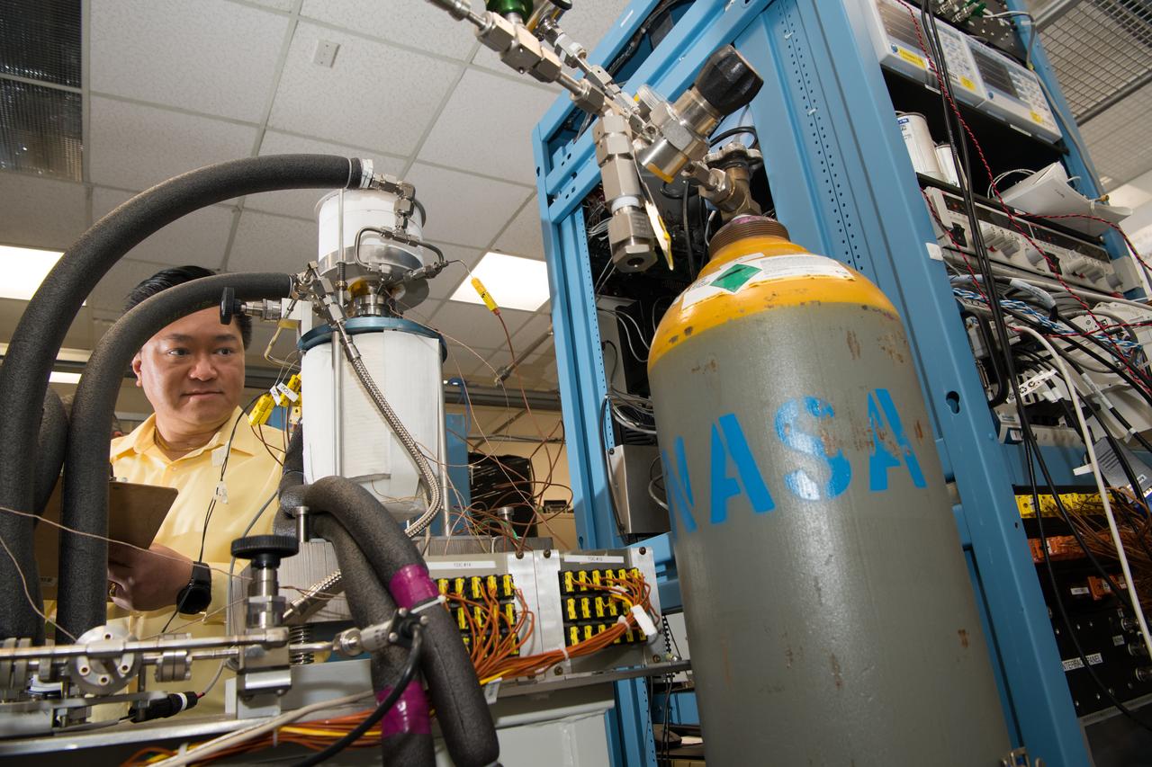
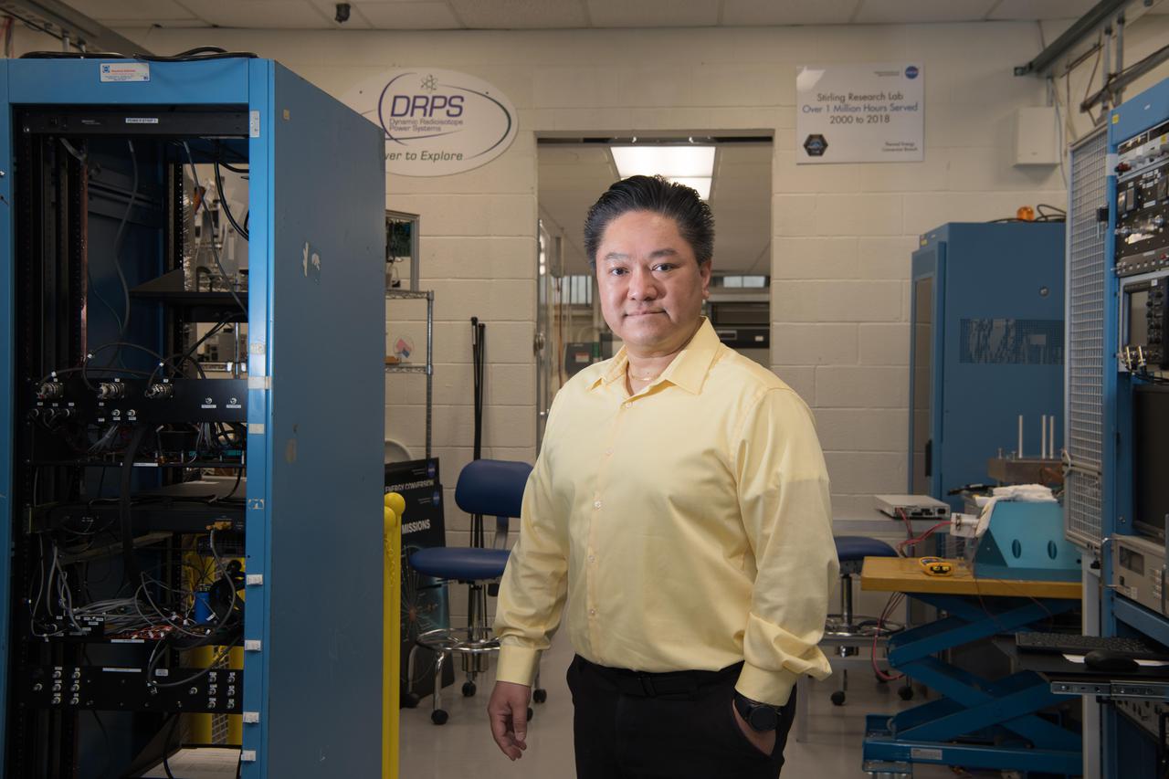
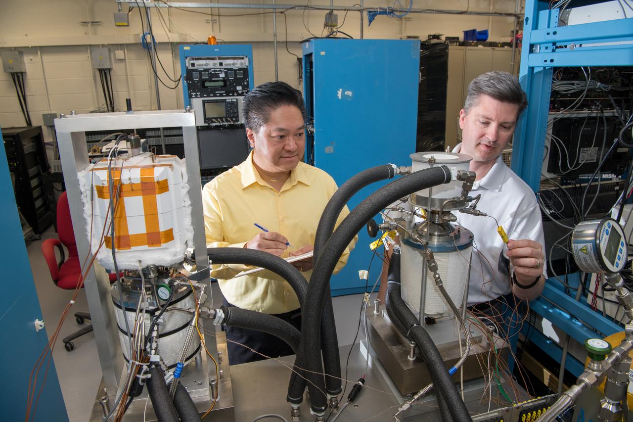
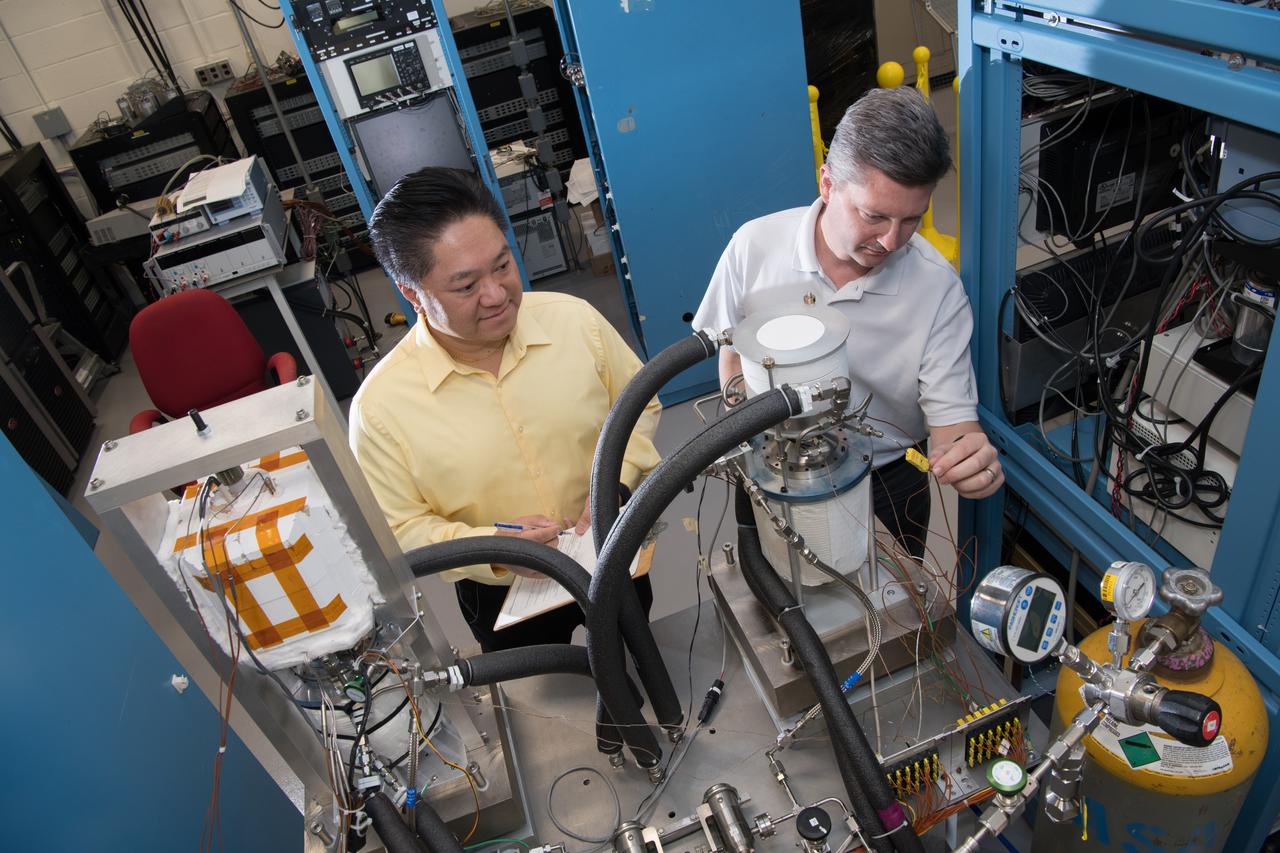
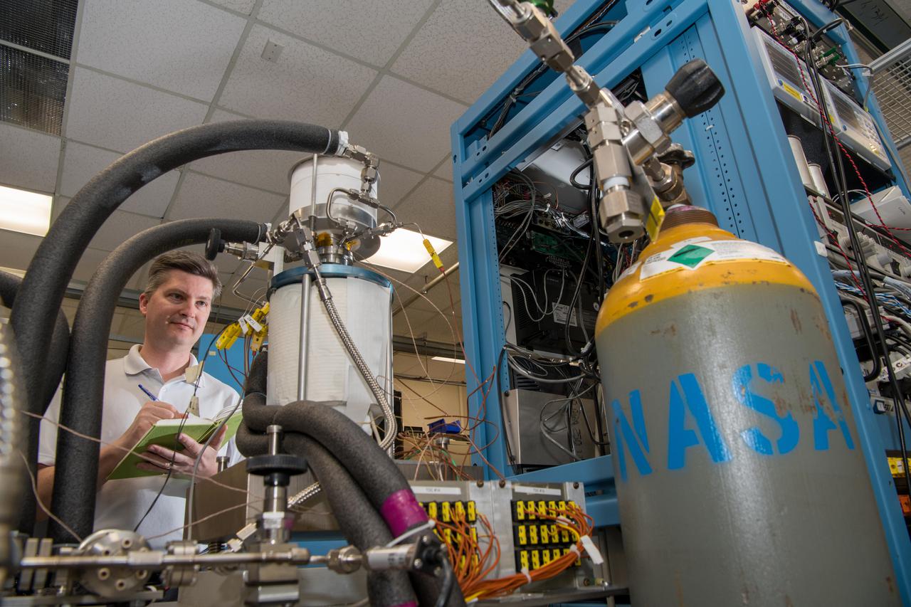
Glenn’s Technology Demonstration Convertor (TDC) #13, a free-piston Stirling power convertor, achieved a milestone of 14 years of maintenance-free operation in the Stirling Research Laboratory in building 301. This technology is proving our capability to power spacecraft on longer-duration future scientific missions.
Glenn’s Technology Demonstration Convertor (TDC) #13, a free-piston Stirling power convertor, achieved a milestone of 14 years of maintenance-free operation in the Stirling Research Laboratory in building 301. This technology is proving our capability to power spacecraft on longer-duration future scientific missions.
Glenn’s Technology Demonstration Convertor (TDC) #13, a free-piston Stirling power convertor, achieved a milestone of 14 years of maintenance-free operation in the Stirling Research Laboratory in building 301. This technology is proving our capability to power spacecraft on longer-duration future scientific missions.
Glenn’s Technology Demonstration Convertor (TDC) #13, a free-piston Stirling power convertor, achieved a milestone of 14 years of maintenance-free operation in the Stirling Research Laboratory in building 301. This technology is proving our capability to power spacecraft on longer-duration future scientific missions.
Glenn’s Technology Demonstration Convertor (TDC) #13, a free-piston Stirling power convertor, achieved a milestone of 14 years of maintenance-free operation in the Stirling Research Laboratory in building 301. This technology is proving our capability to power spacecraft on longer-duration future scientific missions.
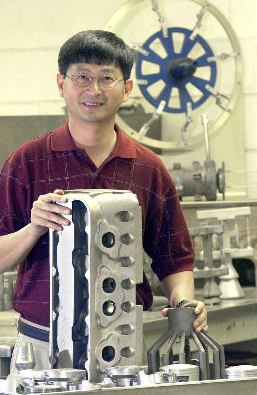
NASA structural materials engineer, Jonathan Lee, displays blocks and pistons as examples of some of the uses for NASA’s patented high-strength aluminum alloy originally developed at Marshall Space Flight Center in Huntsville, Alabama. NASA desired an alloy for aerospace applications with higher strength and wear-resistance at elevated temperatures. The alloy is a solution to reduce costs of aluminum engine pistons and lower engine emissions for the automobile industry. The Boats and Outboard Engines Division at Bombardier Recreational Products of Sturtevant, Wisconsin is using the alloy for pistons in its Evinrude E-Tec outboard engine line.
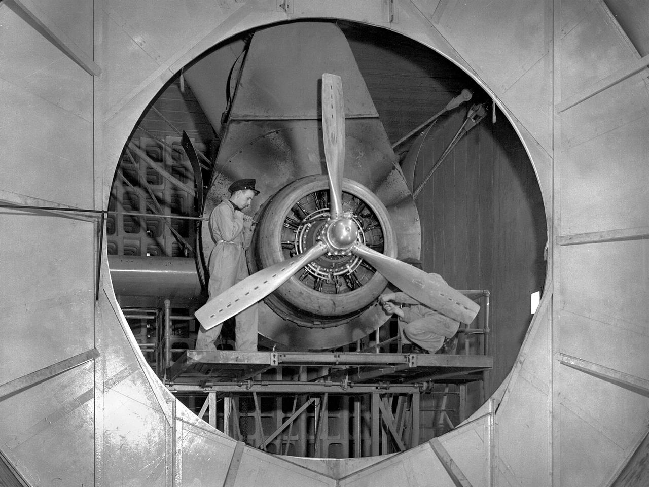
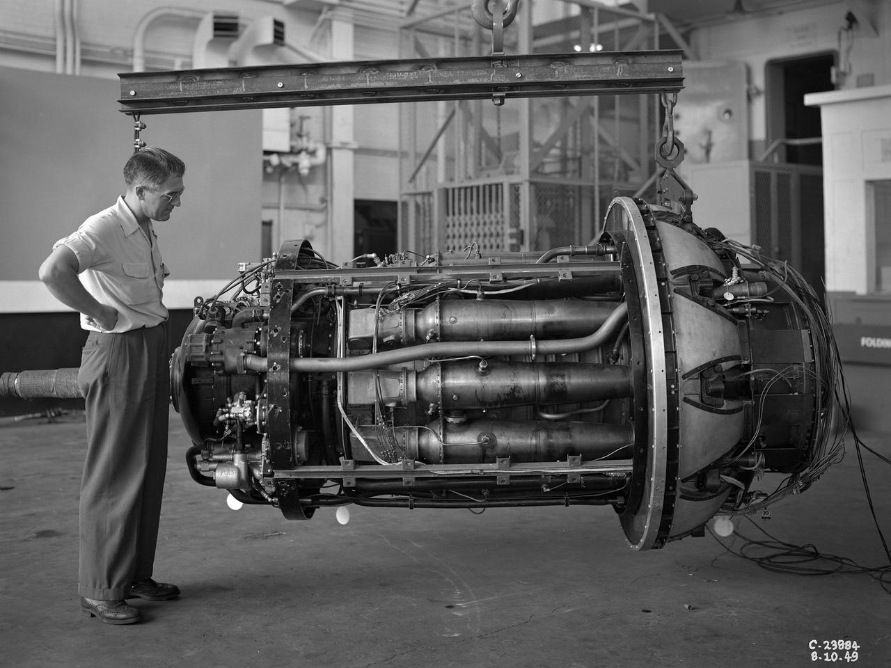
A Wright Aeronautical R–2600 Cyclone piston engine installed in the Engine Propeller Research Building, or Prop House, at the National Advisory Committee for Aeronautics (NACA) Aircraft Engine Research Laboratory. The R–2600 was among the most powerful engines that emerged during World War II. The engine, which was developed for commercial applications in 1939, was used to power the North American B–25 bomber and several other midsize military aircraft. The higher altitudes required by the military caused problems with the engine's cooling and fuel systems. The military requested that the Aircraft Engine Research Laboratory analyze the performance of the R–2600, improve its cooling system, and reduce engine knock. The NACA researchers subjected the engine to numerous tests in its Prop House. The R–2600 was the subject of the laboratory's first technical report, which was written by members of the Fuels and Lubricants Division. The Prop House contained soundproof test cells in which piston engines and propellers were mounted and operated at high powers. Electrically driven fans drew air through ducts to create a stream of cooling air over the engines. Researchers tested the performance of fuels, turbochargers, water-injection and cooling systems here during World War II. The facility was also investigated a captured German V–I buzz bomb during the war.
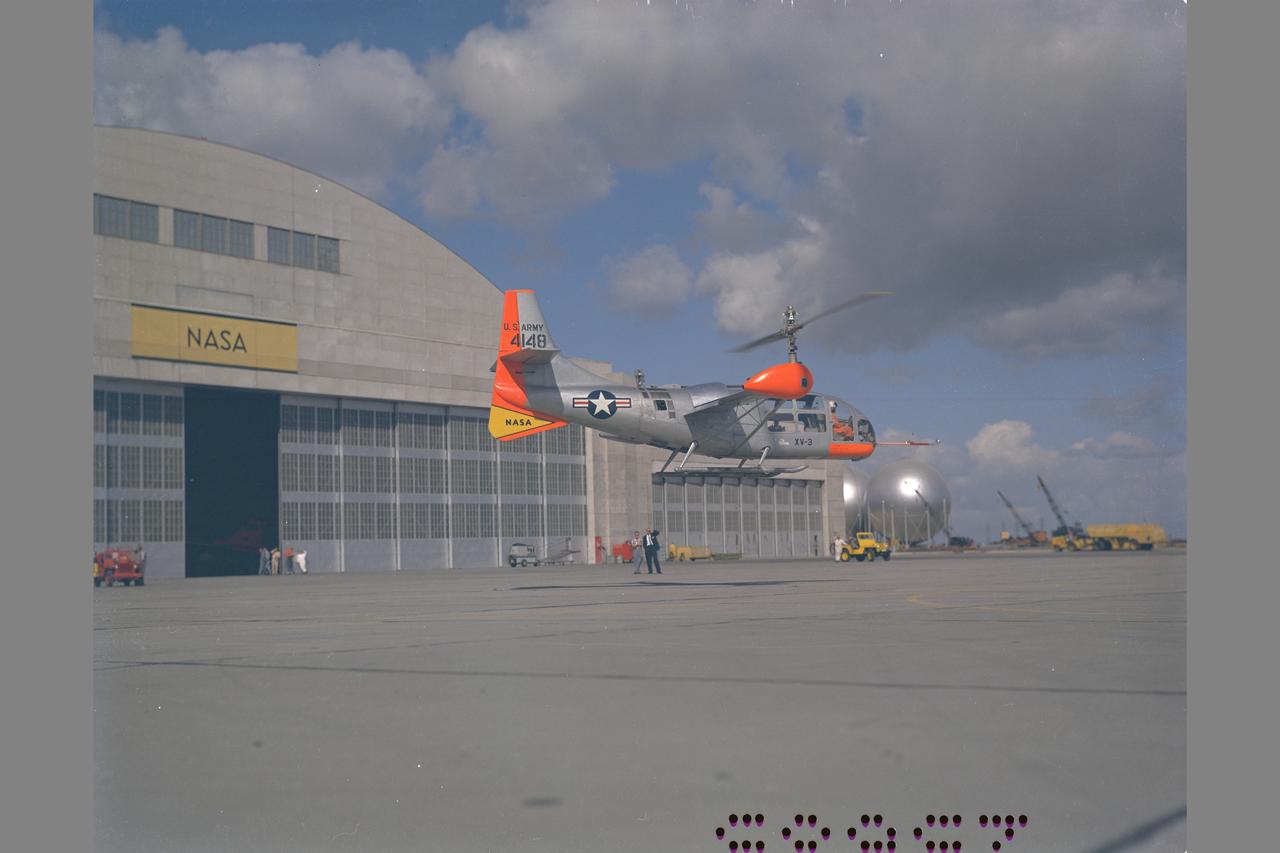
XV-3 HOVERING ON RAMP. Flight Test of Bell XV-3 Convertiplane. Bell VTOL tilt-rotor aircraft hovering in front of building N-211 at Moffett Field. The XV-3 design combined a helicopter rotor and a wing. A 450 horsepower Pratt & Whitney piston engine drove the two rotors. The XV-3, first flown in 1955 , was the first tilt-rotor to achieve 100% tilting of rotors. The vehicle was underpowered, however, and could not hover out of ground effect. Note the large ventral fin, which was added to imrpove directional stability in cruse (Oct 1962)
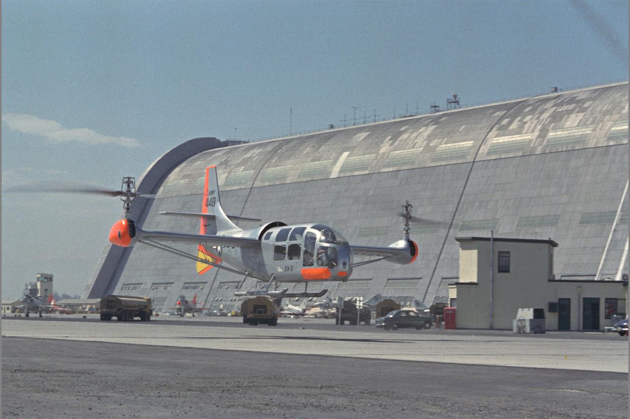
XV-3 HOVERING ON RAMP. Flight Test of Bell XV-3 Convertiplane. Bell VTOL tilt-rotor aircraft hovering along side Hangar One at Moffett Field. The XV-3 design combined a helicopter rotor and a wing. A 450 horsepower Pratt & Whitney piston engine drove the two rotors. The XV-3, first flown in 1955 , was the first tilt-rotor to achieve 100% tilting of rotors. The vehicle was underpowered, however, and could not hover out of ground effect. Note the large ventral fin, which was added to imrpove directional stability in cruse (Oct 1962)
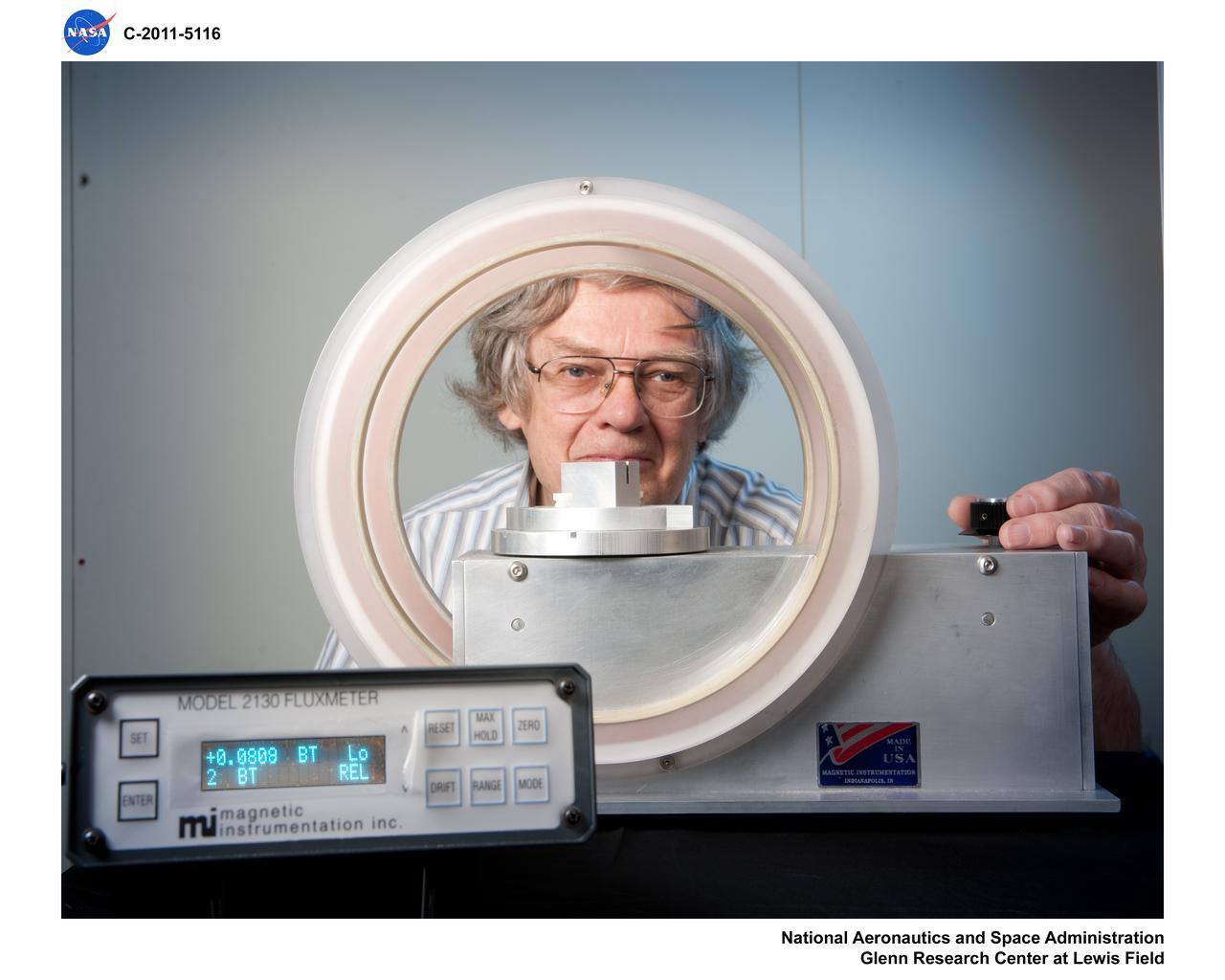
Janis Niedra (RPT/Thermal Energy Conversion Branch) is using a Helmholtz coil to measure the approximate remanence of a magnet segment. The magnet segment being measured is similar to the ones used in the linear alternator of the Advanced Stirling Convertor (ASC) which was designed and built by Sunpower, Inc. The magnet (not shown in this view) is positioned in the slot cut along the top of the aluminum block which is positioned at the center of the coil in the region of uniform sensitivity. The ASC is the type of free-piston Stirling convertor that is used in the Advanced Stirling Radioisotope Generator (ASRG) currently being developed by Lockheed-Martin for the Department of Energy and NASA.

The Roman Coronagraph Instrument on NASA's upcoming Nancy Grace Roman Space Telescope will test new tools that block starlight, revealing planets hidden by the glare of their parent stars. This graphic shows a test of what engineers call "digging the dark hole." The image shows three computer readouts of real data from the coronagraph's camera. Engineers used lasers and special optics to replicate the light from a star as it would look when observed by the Roman telescope. The image at left shows the amount of starlight that leaks into the coronagraph's field of view when only fixed components called masks are used to block the star at the center of the circle. Using moveable components such as deformable mirrors, the coronagraph can remove more and more of this starlight. The middle and right images show the progression of this process, where red indicates less starlight, and black indicates most or all starlight has been removed. The deformable mirrors are each only 2 inches (5 centimeters) in diameter and backed by more than 2,000 tiny pistons that move up and down. The pistons work together to change the shape of the mirrors to compensate for the unwanted stray light that spills around the edges of the masks. Though they are too small to affect Roman's other highly precise measurements, the imperfections can send stray starlight into the dark hole. In space, this technique will enable astronomers to observe light directly from planets around other stars, or exoplanets. Once demonstrated on Roman, similar technologies on a future mission could enable astronomers to use that light to identify chemicals in an exoplanet's atmosphere, potentially indicating the presence of life. https://photojournal.jpl.nasa.gov/catalog/PIA26279
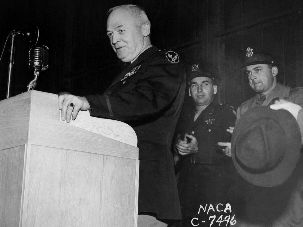
General Henry “Hap” Arnold, Commander of the US Army Air Forces during World War II, addresses the staff at the National Advisory Committee for Aeronautics (NACA) Aircraft Engine Research Laboratory on November 9, 1944. Arnold told the employees assembled in the hangar, “You’ve got a dual task. You’ve got a job ahead of you to keep the army and the navy air forces equipped with the finest equipment that you can for this war. You also have the job of looking forward into the future and starting now those developments, those experiments, that are going to keep us in our present situation—ahead of the world in the air. And that is quite a large order, and I leave it right in your laps.” Arnold served on the NACA’s Executive Committee in Washington from 1938 to 1944 and had been a strong advocate for the creation of the new engine research facility in Cleveland. Arnold believed in continual research and development. He pressed the nation’s aviation leaders to pursue the new jet engine technology, while simultaneously pushing to increase the performance of the nation’s largest piston engine for the B–29 Superfortress program. The general’s hectic wartime agenda limited his visit to the Cleveland laboratory to just a few hours, but he toured several of the NACA’s new test facilities including the Static Jet Propulsion Laboratory, the Icing Research Tunnel, and a B–24 Liberator in the hangar.
A materials researcher at the NACA’s Lewis Flight Propulsion Laboratory examines a surface crack detection apparatus in the Materials and Stresses Building during December 1952. Materials research was an important aspect of propulsion technology. Advanced engine systems relied upon alloys, and later composites, that were strong, lightweight, and impervious to high temperatures. Jet engines which became increasingly popular in the late 1940s, produced much higher temperatures than piston engines. These higher temperatures stressed engine components, particularly turbines. Although Lewis materials research began during World War II, the Materials and Thermodynamics Division was not created until 1949. Its primary laboratories were located in the Materials and Stresses Building. The group sought to create new, improved materials and to improve engine design through increased understanding of materials. The Lewis materials researchers of the 1950s made contributions to nickel-aluminum alloys, cermet blades, metal matrix composites, oxide dispersion strengthened superalloys, and universal slopes.
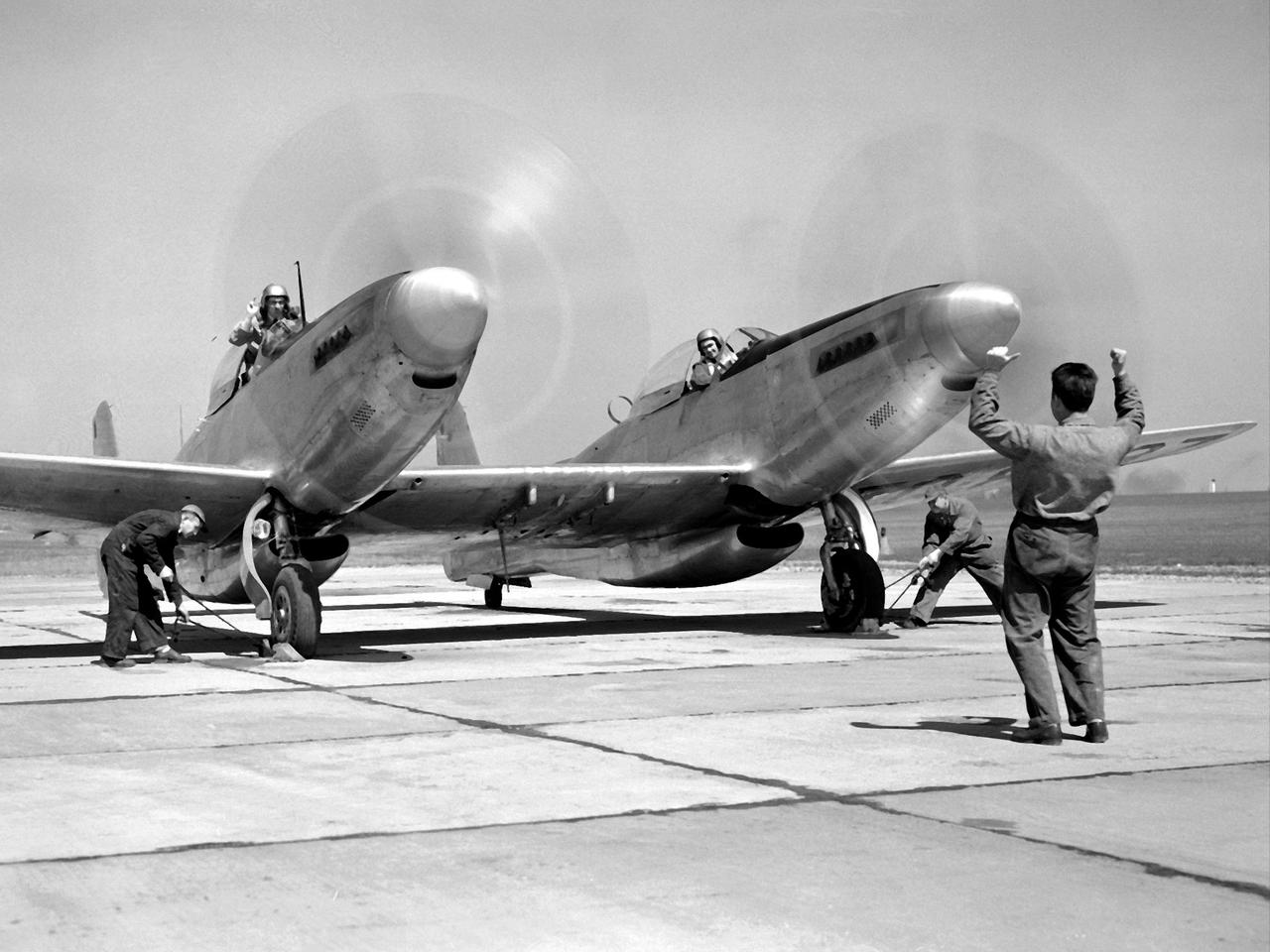
Pilot William Swann, right cockpit, prepares the North American XF-82 Twin Mustang for flight at the National Advisory Committee for Aeronautics (NACA) Lewis Flight Propulsion Laboratory. The aircraft was one of only two prototypes built by North American in October 1945 and powered by Packard Merlin V-1650 piston engines. Over 270 of the F-82 long-distance pursuit fighters were produced during the 1940s. The Mustang’s unique two-pilot configuration allowed one pilot to rest during the long missions and thus be ready for action upon arrival. The NACA took possession of this XF-82 in October 1947. NACA Lewis used the XF-82 as a test bed for ramjet flight tests. Ramjets are continually burning tubes that use the compressed atmospheric air to produce thrust. Ramjets are extremely efficient at high speeds, but rely on some sort of booster to attain that high speed. NACA Lewis undertook an extensive ramjet program in the 1940s that included combustion studies in the Altitude Wind Tunnel, a number of flight tests, and missile drops from aircraft. The 16-inch diameter ramjet missile was fixed to the XF-82 Mustang’s wing and dropped from high altitudes off of Wallops Island. The tests determined the ramjet’s performance and operational characteristics in the transonic range.
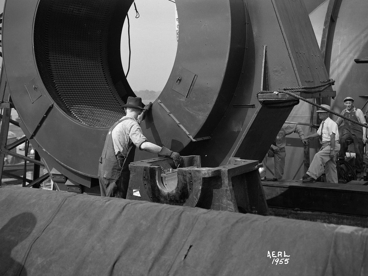
Construction workers install the drive motor for the Altitude Wind Tunnel (AWT) in the Exhauster Building at the National Advisory Committee for Aeronautics (NACA) Aircraft Engine Research Laboratory. The AWT was capable of operating full-scale engines in air density, speed, and temperature similar to that found at high altitudes. The tunnel could produce wind speeds up to 500 miles per hour through a 20-foot-diameter test section at the standard operating altitude of 30,000 feet. The airflow was created by a large wooden fan near the tunnel’s southeast corner. This photograph shows the installation of the 18,000-horsepower drive motor inside the adjoining Exhauster Building in July 1943. The General Electric motor, whose support frame is seen in this photograph, connected to a drive shaft that extended from the building, through the tunnel shell, and into a 12-bladed, 31-foot-diameter spruce wood fan. Flexible couplings on the shaft allowed for the movement of the shell. The corner of the Exhauster Building was built around the motor after its installation. The General Electric induction motor could produce 10 to 410 revolutions per minute and create wind speeds up to 500 miles per hour, or Mach 0.63, at 30,000 feet. The AWT became operational in January 1944 and tested piston, turbojet and ramjet engines for nearly 20 years.
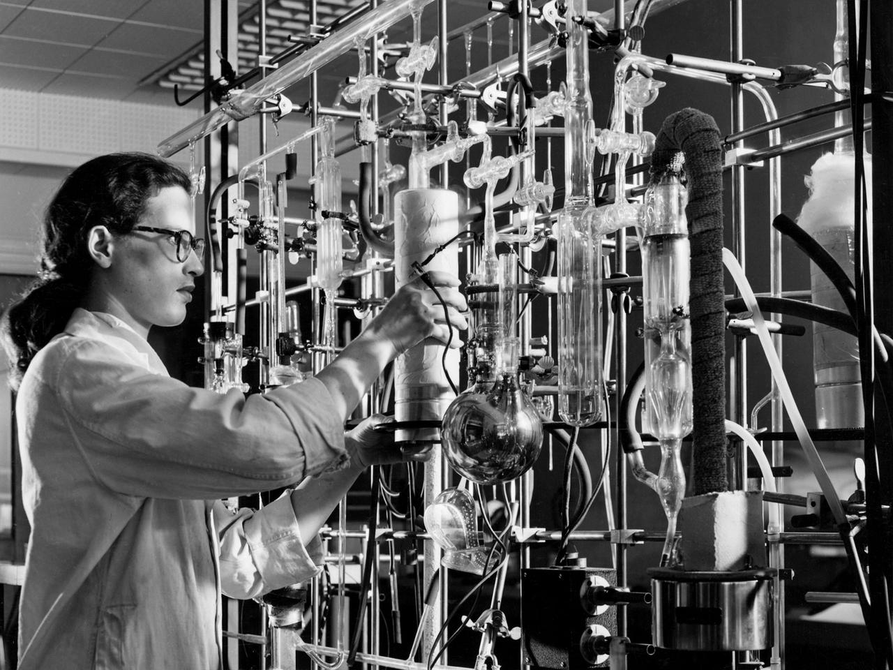
![A researcher at the National Advisory Committee for Aeronautics (NACA) Aircraft Engine Research Laboratory studies the fuel ignition process. Improved fuels and lubrication was an area of particular emphasis at the laboratory during World War II. The military sought to use existing types of piston engines in order to get large numbers of aircraft into the air as quickly as possible. To accomplish its goals, however, the military needed to increase the performance of these engines without having to wait for new models or extensive redesigns. The Aircraft Engine Research Laboratory was called on to lead this effort. The use of superchargers successfully enhanced engine performance, but the resulting heat increased engine knock [fuel detonation] and structural wear. These effects could be offset with improved cooling, lubrication, and fuel mixtures. The NACA researchers in the Fuels and Lubrication Division concentrated on new synthetic fuels, higher octane fuels, and fuel-injection systems. The laboratory studied 16 different types of fuel blends during the war, including extensive investigations of triptane and xylidine.](https://images-assets.nasa.gov/image/GRC-1943-C-02124/GRC-1943-C-02124~medium.jpg)
A researcher at the National Advisory Committee for Aeronautics (NACA) Aircraft Engine Research Laboratory studies the fuel ignition process. Improved fuels and lubrication was an area of particular emphasis at the laboratory during World War II. The military sought to use existing types of piston engines in order to get large numbers of aircraft into the air as quickly as possible. To accomplish its goals, however, the military needed to increase the performance of these engines without having to wait for new models or extensive redesigns. The Aircraft Engine Research Laboratory was called on to lead this effort. The use of superchargers successfully enhanced engine performance, but the resulting heat increased engine knock [fuel detonation] and structural wear. These effects could be offset with improved cooling, lubrication, and fuel mixtures. The NACA researchers in the Fuels and Lubrication Division concentrated on new synthetic fuels, higher octane fuels, and fuel-injection systems. The laboratory studied 16 different types of fuel blends during the war, including extensive investigations of triptane and xylidine.

This image shows a complex set of fractures found in the southwestern region of the floor of Occator Crater on Ceres. In this picture, north is at the top. The two intersecting fracture systems (roughly northwest-southeast and southwest-northeast) are part of a larger fault network that extends across Occator's floor. These fractures have been interpreted as evidence that material came up from below and formed a dome shape, as if a piston was pushing Occator's floor from beneath the surface. This may be due to the upwelling of material coming from Ceres' deep interior. An alternative hypothesis is that the deformation is due to volume changes inside a reservoir of icy magma in the shallow subsurface that is in the process of freezing, similar to the change in volume that a bottle of water experiences when put in a freezer. Another set of fractures can be seen parallel to the southwestern wall and is not connected to the Occator fracture network. Dawn took this image during its extended mission on August 17, 2016, from its low-altitude mapping orbit, at a distance of about 240 miles (385 kilometers) above the surface. The image resolution is 120 feet (35 meters) per pixel. The center coordinates are 16 degrees north in latitude and 237 east in longitude. https://photojournal.jpl.nasa.gov/catalog/PIA22091
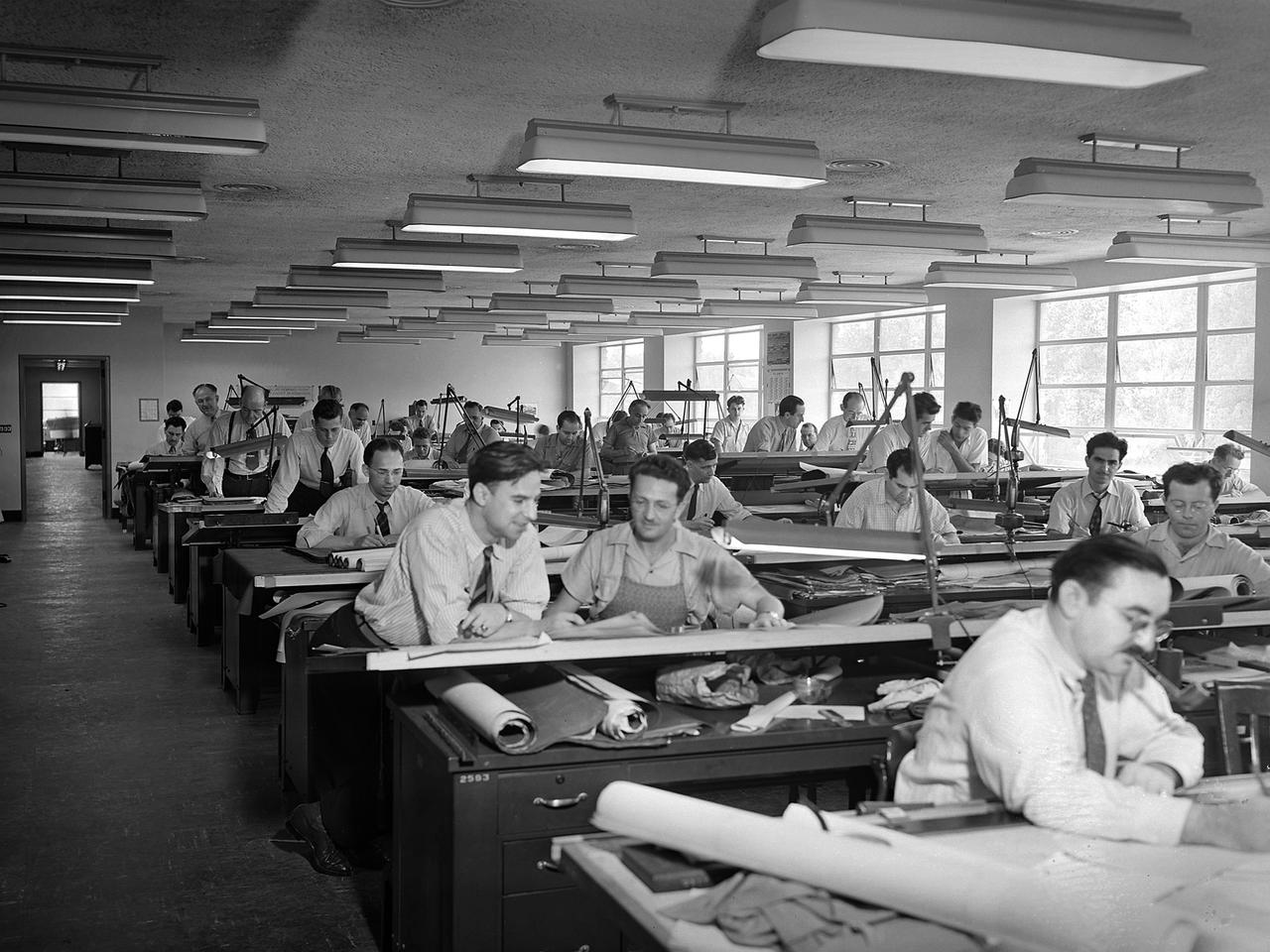
The National Advisory Committee for Aeronautics (NACA) Aircraft Engine Research Laboratory was designed by a group of engineers at the Langley Memorial Aeronautical Laboratory in late 1940 and 1941. Under the guidance of Ernest Whitney, the men worked on drawings and calculations in a room above Langley’s Structural Research Laboratory. The main Aircraft Engine Research Laboratory design group originally consisted of approximately 30 engineers and draftsmen, but there were smaller groups working separately on specific facilities. The new engine lab would have six principal buildings: the Engine Research Building, hangar, Fuels and Lubricants Building, Administration Building, Propeller Test Stand, and Altitude Wind Tunnel. In December 1941 most of those working on the project transferred to Cleveland from Langley. Harrison Underwood and Charles Egan led 18 architectural, 26 machine equipment, 3 structural and 10 mechanical draftsmen. Initially these staff members were housed in temporary offices in the hangar. As sections of the four-acre Engine Research Building were completed in the summer of 1942, the design team began relocating there. The Engine Research Building contained a variety of test cells and laboratories to address virtually every aspect of piston engine research. It also contained a two-story office wing, seen in this photograph that would later house many of the powerplant research engineers.
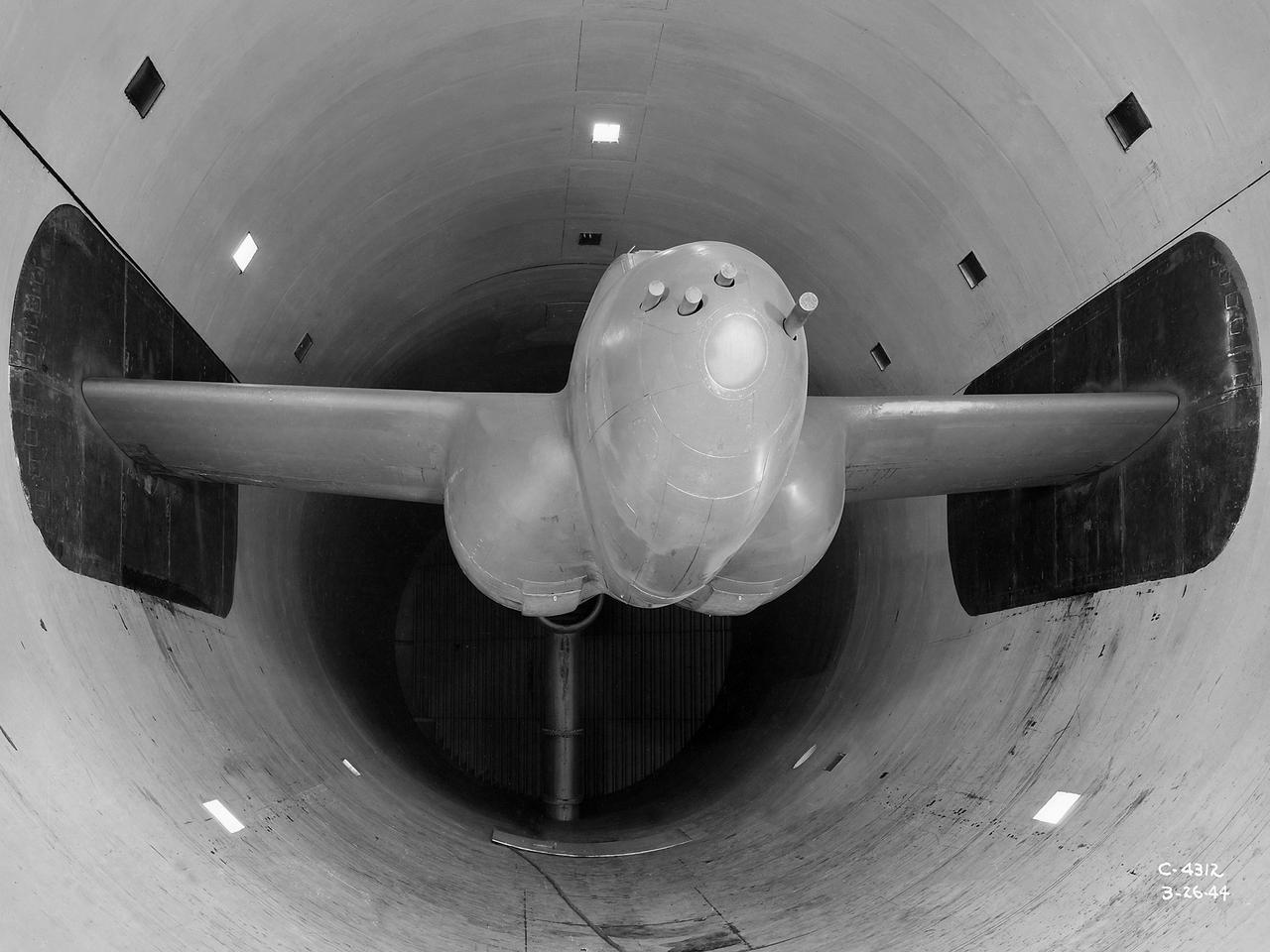
The Altitude Wind Tunnel (AWT) was the National Advisory Committee for Aeronautics (NACA) Aircraft Engine Research Laboratory’s largest and most important test facility in the 1940s. The AWT employed massive cooling and exhaust systems to simulate conditions found at high altitudes. The facility was originally designed to test large piston engines in a simulated flight environment. The introduction of the turbojet during the tunnel’s construction, however, changed the facility’s focus before it became operational. Its first test program was a study of the Bell YP–59A Airacomet and its General Electric I–16 turbojets. The Airacomet was the United States’ first attempt to build a jet aircraft. 1600-horsepower centrifugal engines based on an early design by British engineer Frank Whittle were incorporated into an existing Bell airframe. In October 1942 the Airacomet was secretly test flown in the California desert. The aircraft’s performance was limited, however, and the NACA was asked to study the engines in the AWT. The wind tunnel’s 20-foot-diameter test section was large enough to accommodate entire aircraft with its wing tips and tail removed. The I-16 engines were studied exhaustively in early 1944. They first analyzed the engines in their original configuration and then implemented a boundary layer removal duct, a new nacelle inlet, and new cooling seals. Tests of the modified version showed that the improved distribution of airflow increased the I–16’s performance by 25 percent. The Airacomet never overcame some of its inherent design issues, but the AWT went on to study nearly every emerging US turbojet model during the next decade.
A 3670-horsepower Armstrong-Siddeley Python turboprop being prepared for tests in the Altitude Wind Tunnel at the National Advisory Committee for Aeronautics (NACA) Lewis Flight Propulsion Laboratory. In 1947 Lewis researcher Walter Olsen led a group of representatives from the military, industry, and the NACA on a fact finding mission to investigate the technological progress of British turbojet manufacturers. Afterwards several British engines, including the Python, were brought to Cleveland for testing in Lewis’s altitude facilities. The Python was a 14-stage axial-flow compressor turboprop with a fixed-area nozzle and contra-rotating propellers. Early turboprops combined the turbojet and piston engine technologies. They could move large quantities of air so required less engine speed and thus less fuel. This was very appealing to the military for some applications. The military asked the NACA to compare the Python’s performance at sea to that at high altitudes. The NACA researchers studied the Python in the Altitude Wind Tunnel from July 1949 through January 1950. It was the first time the tunnel was used to study an engine with the sole purpose of learning about, not improving it. They analyzed the engine’s dynamic response using a frequency response method at altitudes between 10,000 to 30,000 feet. Lewis researchers found that they could predict the dynamic response characteristics at any altitude from the data obtained from any other specific altitude. This portion of the testing was completed during a single test run.

A Lockheed P-80 Shooting Star jet aircraft on the tarmac at the National Advisory Committee for Aeronautics (NACA) NACA Lewis Flight Propulsion Laboratory in Cleveland, Ohio. The Air Force aircraft was participating in the 1946 National Air Races over Labor Day weekend. The air races were held at the Cleveland Municipal Airport seven times between 1929 and 1939. The events included long distance, sprint, and circuit competitions, as well as aeronautical displays, demonstrations, and celebrities. The air races were suspended indefinitely in 1940 for a variety of reasons, including the start of World War II in Europe. The nature of the National Air Races changed dramatically when the event resumed in 1946. The introduction of jet aircraft, primarily the Lockheed P-80 seen here, required an entire separate division for each event. Since military pilots were the only ones with any jet aircraft experience, only they could participate in those divisions. In addition, the performance and quantity of commercially manufactured piston aircraft had increased dramatically during the war. By 1946, the custom-built racing aircraft that made the pre-war races so interesting were no longer present. The P-80 was the first US-designed and US-manufactured jet aircraft. Early models were tested during the war in NACA Lewis’ Altitude Wind Tunnel. A modified P-80 set the world’s speed record at the 1947 air races by achieving 620 miles per hour.