The Super Position
95-degree Position on Mars
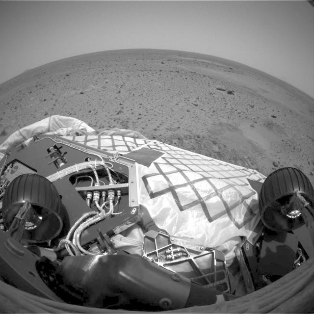
Spirit Wiggles into Position
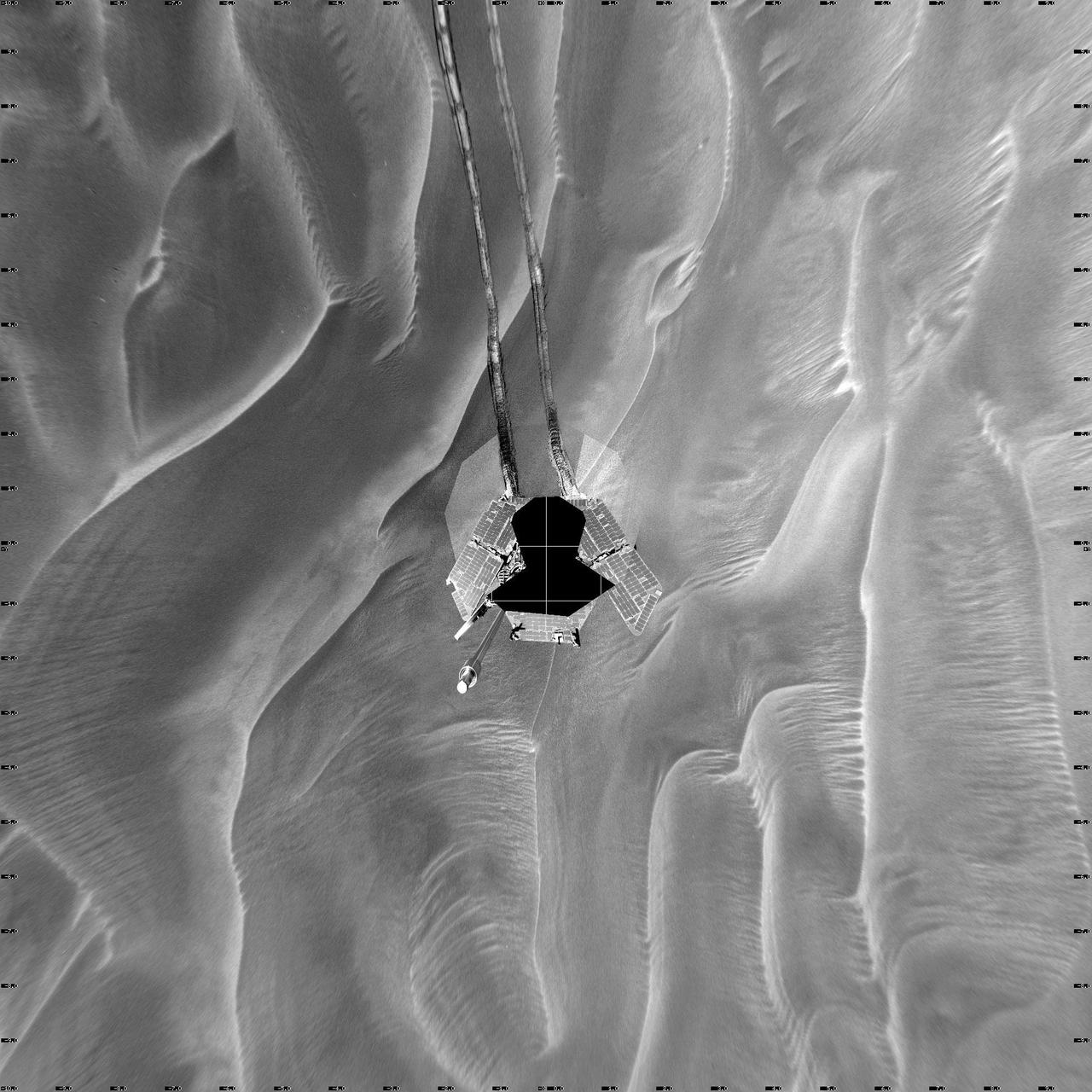
Opportunity Arm in Hover-Stow Position
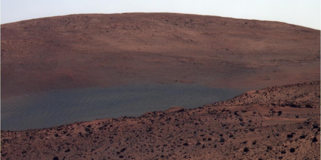
View from Spirit Overwintering Position False Color
Opportunity Sol 446 Position, with Relative Heights
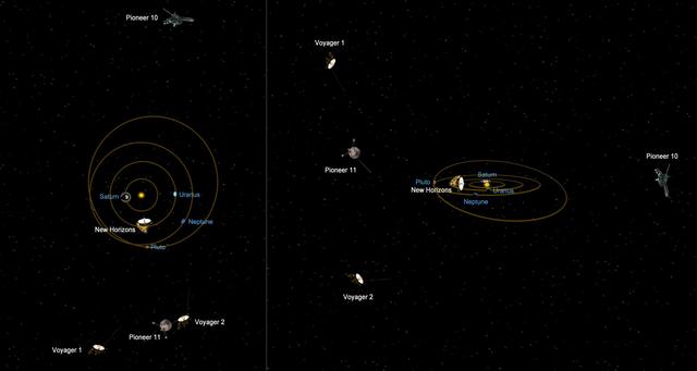
This graphic shows the relative positions of NASA most distant spacecraft in early 2011, looking at the solar system from the side. Voyager 1 is the most distant spacecraft, 10.9 billion miles away from the sun at a northward angle.
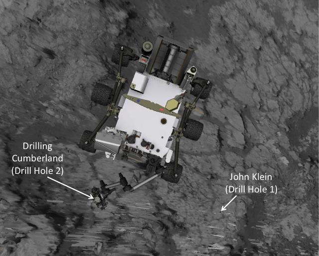
This image produced from software used for planning drives of NASA Mars rover Curiosity depicts the location and size of the rover when it was driven into position for drilling into rock target Cumberland.
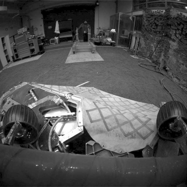
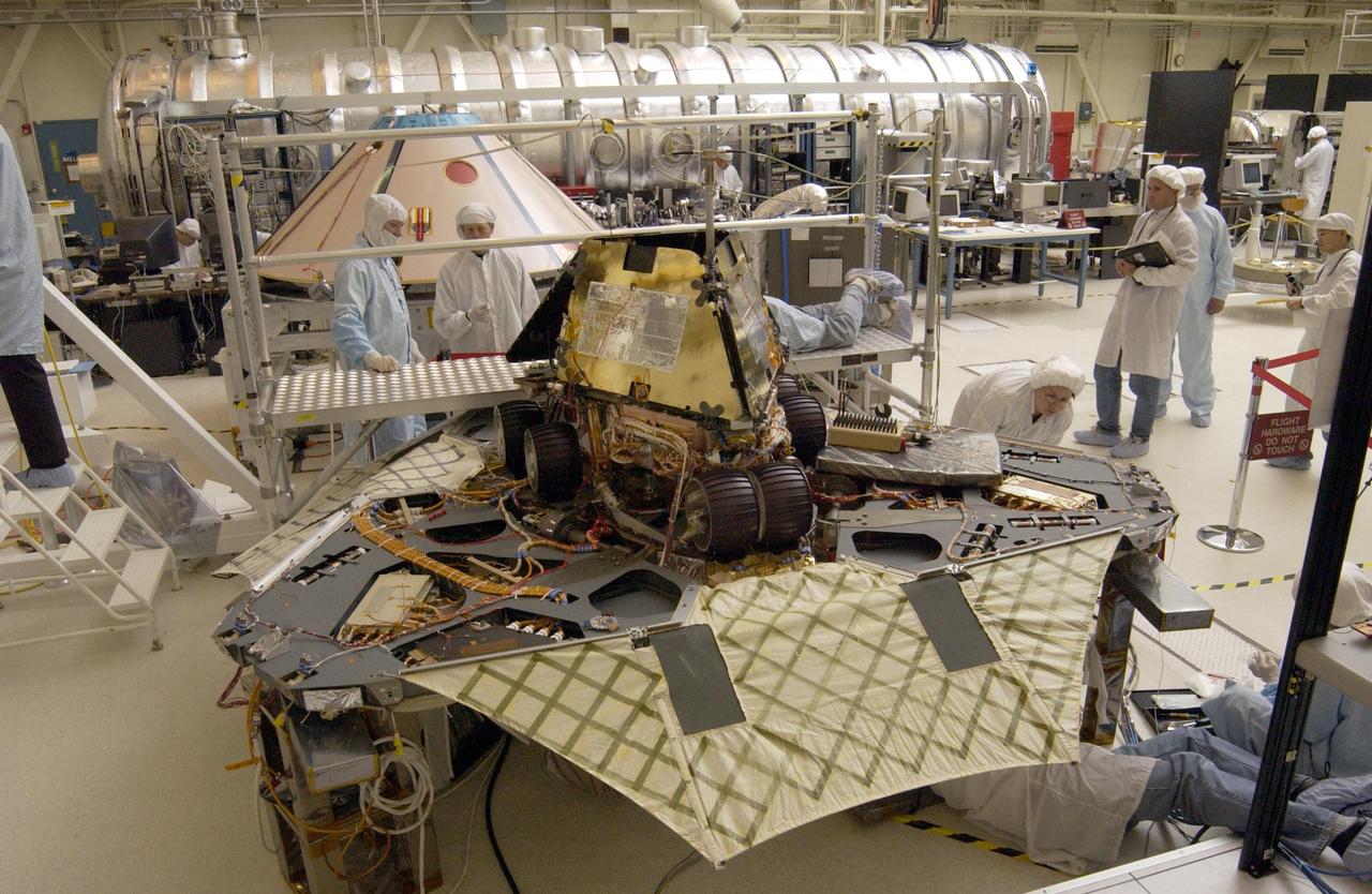
This image shows a test rover in a near-final turned position on the lander in NASA Jet Propulsion Laboratory In-Situ Instruments Laboratory, or testbed.
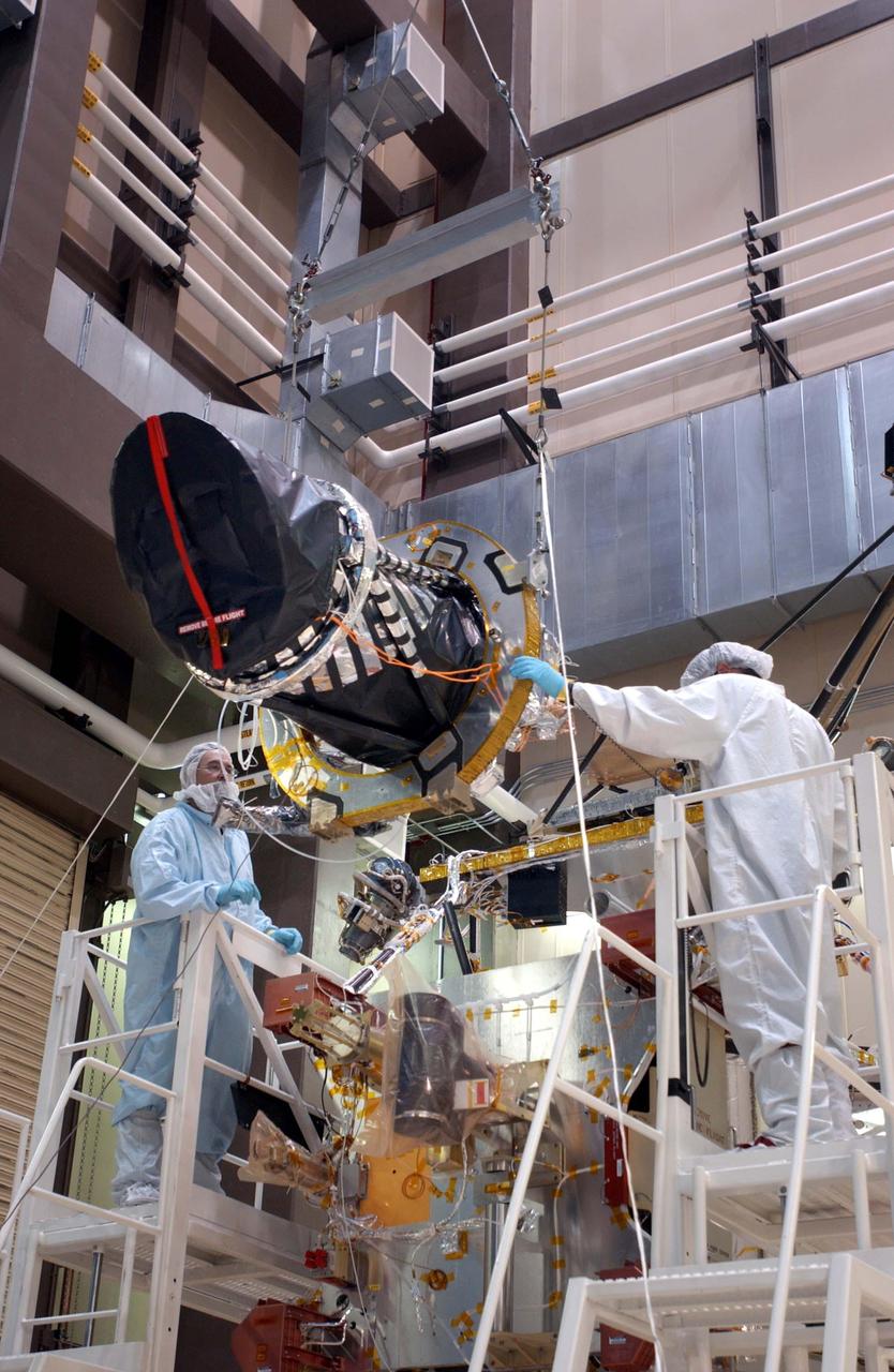
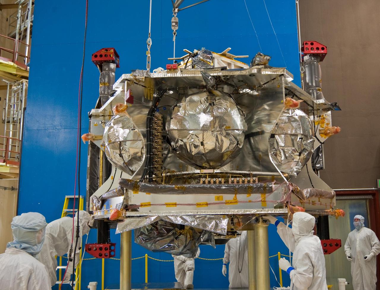
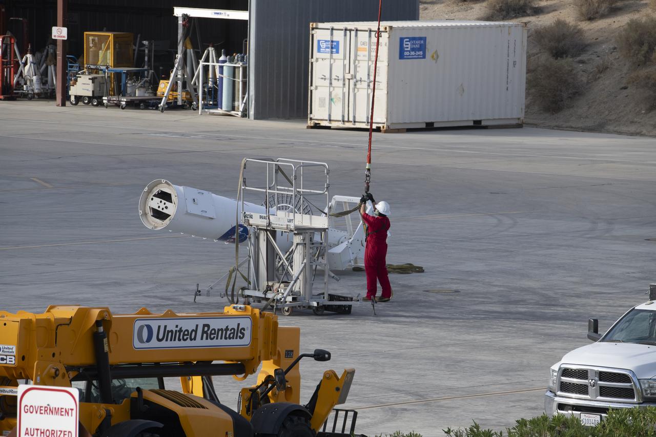
Workers at Lockheed Martin Space Systems, Denver, position a telescopic camera for installation onto NASA Mars Reconnaissance Orbiter spacecraft on Dec. 11, 2004.

Matt Johnson, CAPSTONE lead systems engineer, left, and Dylan Schmidt, CAPSTONE assembly integration and test lead, right, with the CAPSTONE spacecraft stowed in its dispenser at Tyvak Nano-Satellite Systems, Inc., in Irvine, California.
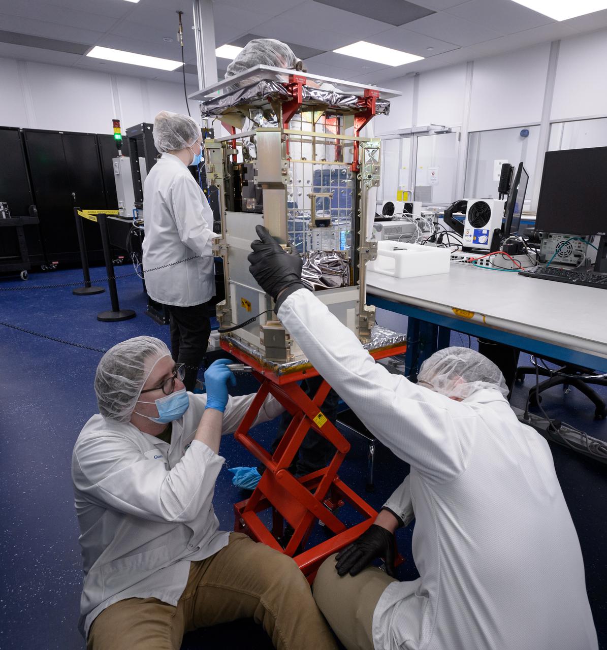
Matt Johnson, CAPSTONE lead systems engineer, bottom, Dustin Holta, launch engineer, right, and Rebecca Rogers, systems engineer, background, with the CAPSTONE spacecraft stowed in its dispenser at Tyvak Nano-Satellite Systems, Inc., in Irvine, California.
Rebecca Rogers, systems engineer, left, and Dustin Holta, launch engineer, right, mount a cover plate to the CAPSTONE spacecraft dispenser with the spacecraft stowed inside at Tyvak Nano-Satellite Systems, Inc., in Irvine, California.
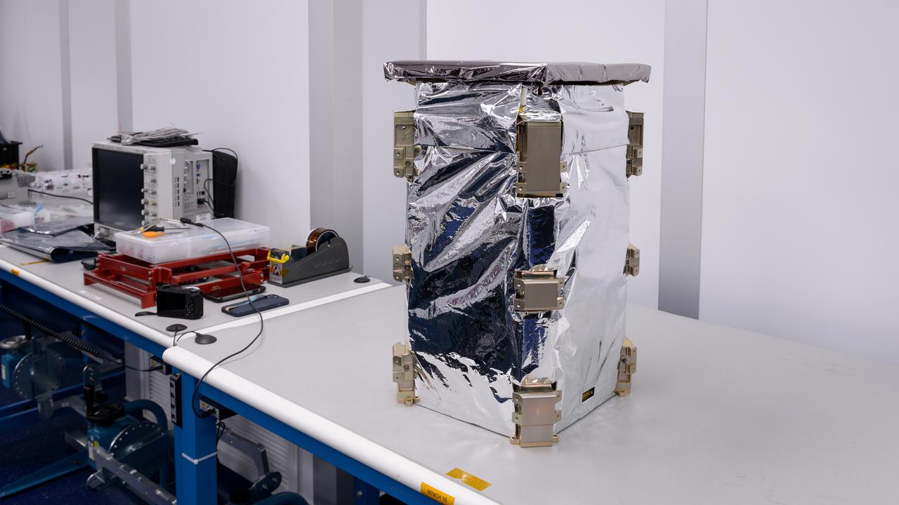
The CAPSTONE spacecraft dispenser in a thermal blanket with the spacecraft stowed inside at Tyvak Nano-Satellite Systems, Inc., in Irvine, California.
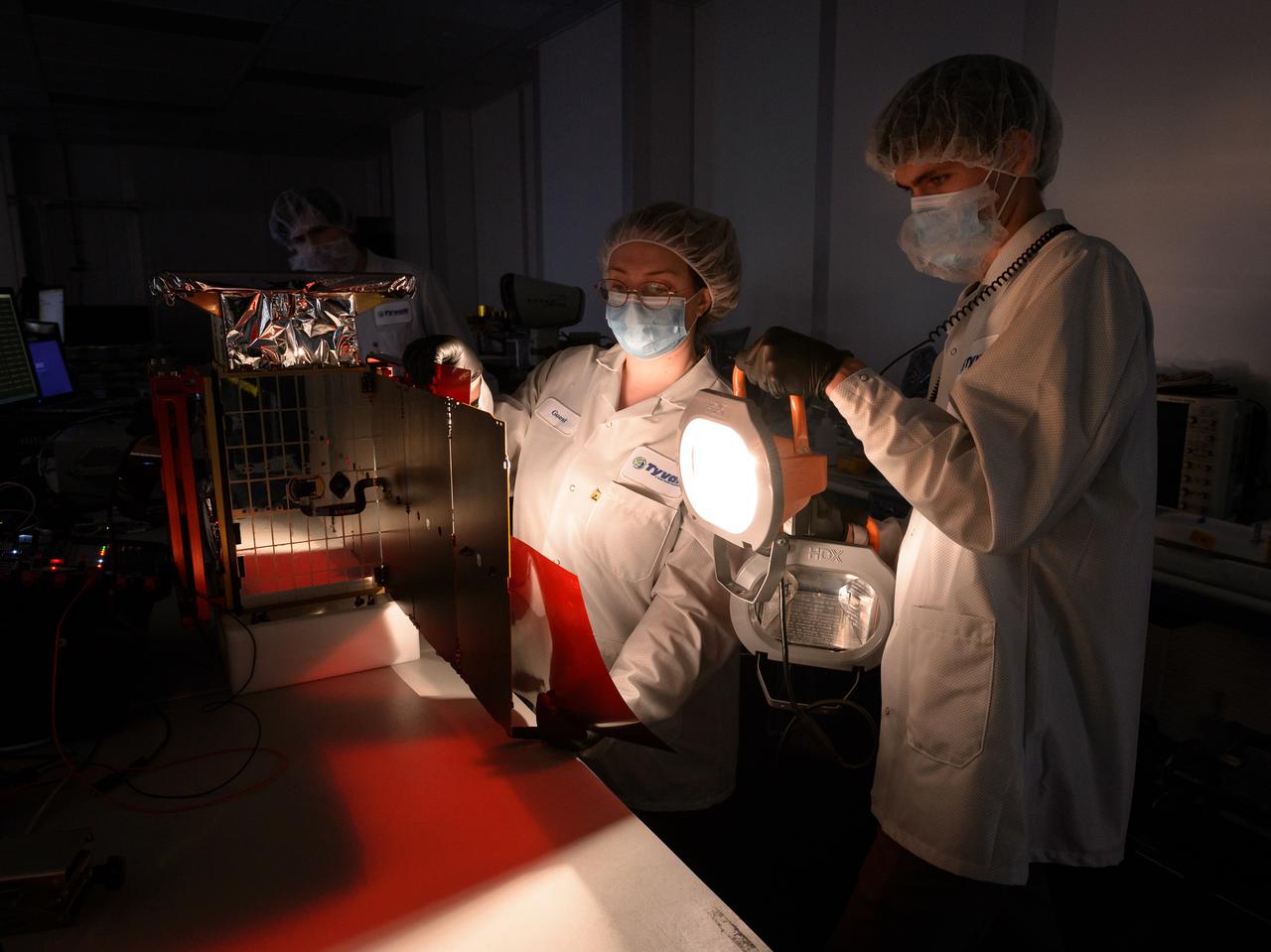
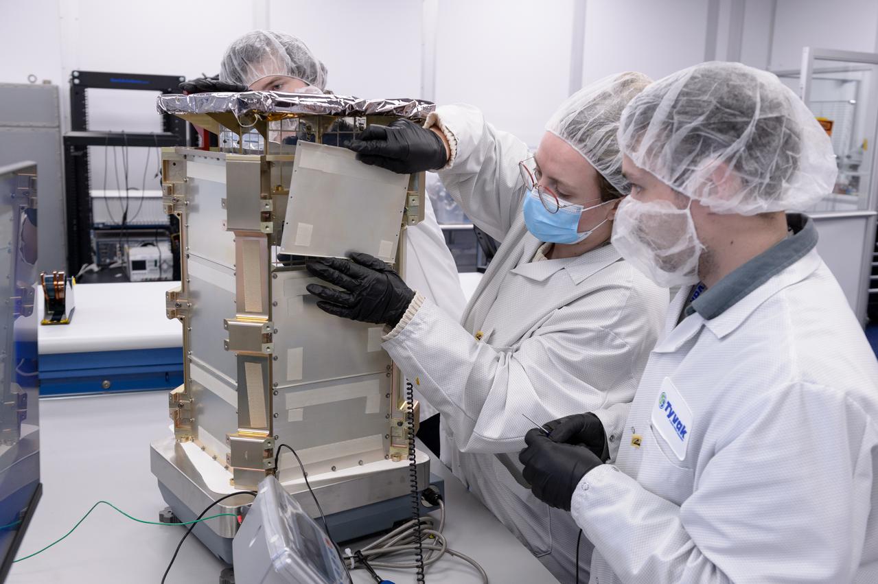
Rebecca Rogers, systems engineer, center, Lachlan Moore, systems integration engineer, right, and Dylan Schmidt, CAPSTONE assembly integration and test lead, background, perform a solar panel string voltage test of the CAPSTONE spacecraft at Tyvak Nano-Satellite Systems, Inc., in Irvine, California.
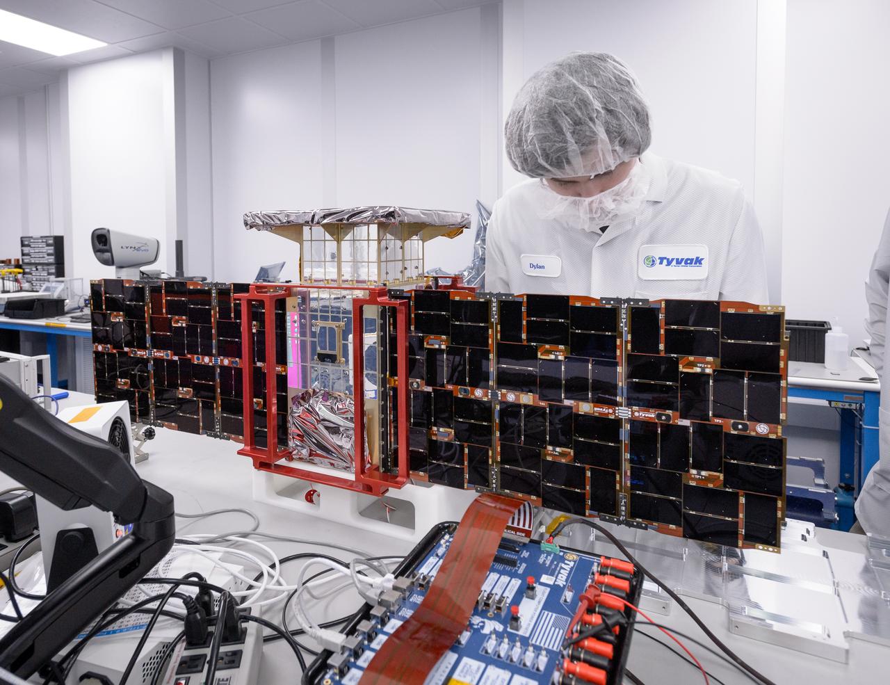
Dylan Schmidt, CAPSTONE assembly integration and test lead, installs solar panels onto the CAPSTONE spacecraft at Tyvak Nano-Satellite Systems, Inc., in Irvine, California.
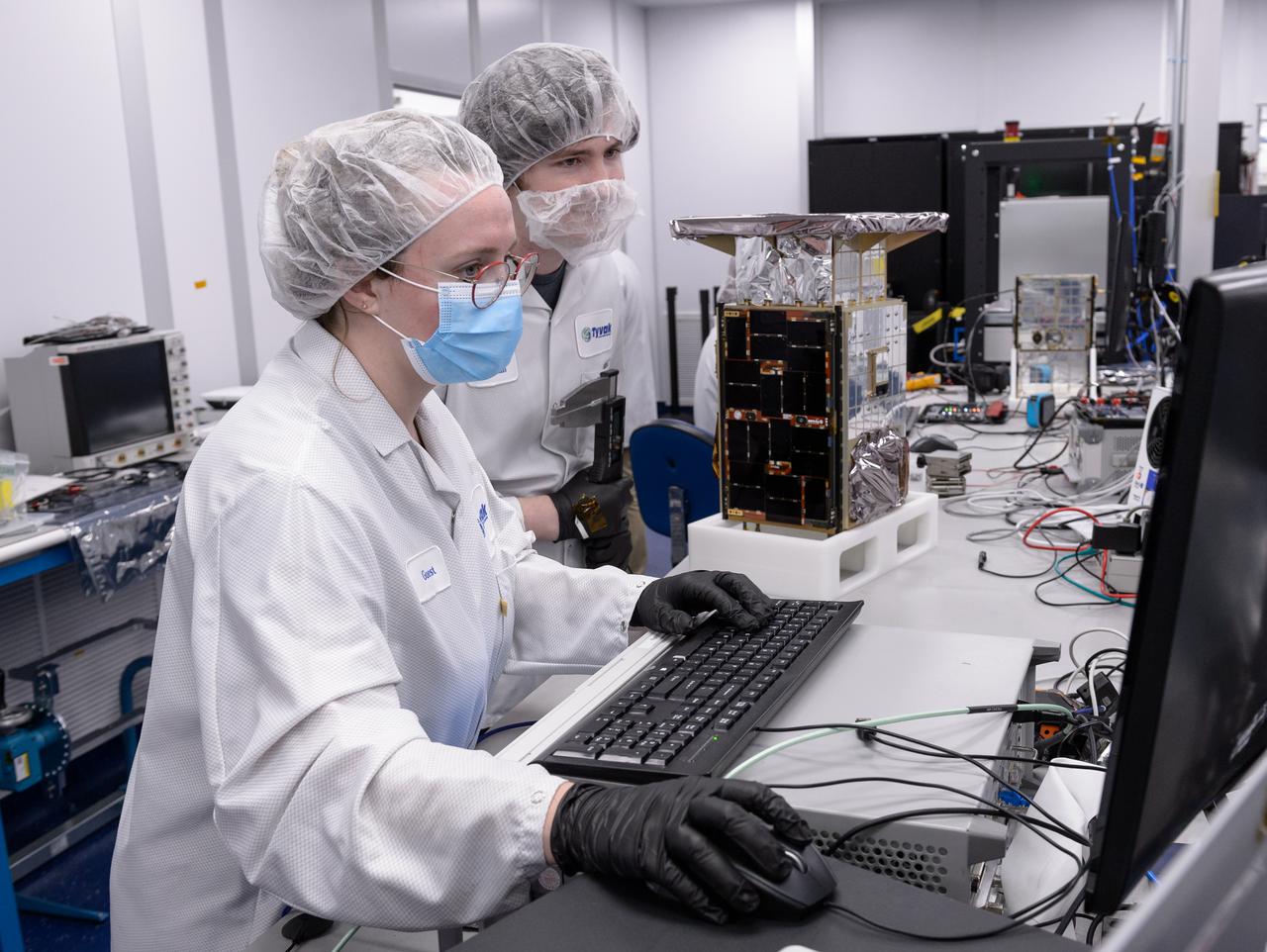
Dylan Schmidt, CAPSTONE assembly integration and test lead, right, and Rebecca Rogers, systems engineer, left, take dimension measurements of the CAPSTONE spacecraft at Tyvak Nano-Satellite Systems, Inc., in Irvine, California.
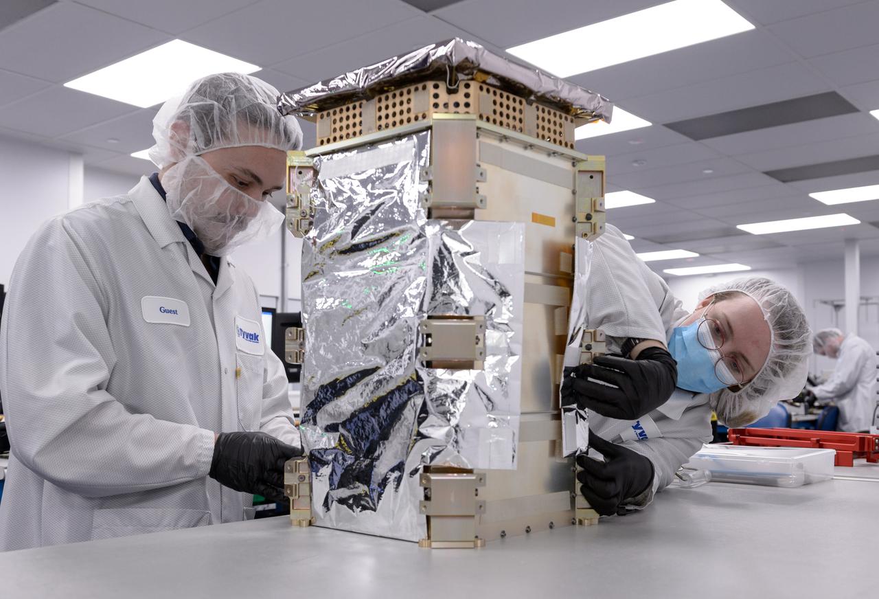
Dustin Holta, launch engineer, left, and Rebecca Rogers, systems engineer, right, wrap the CAPSTONE spacecraft dispenser in a thermal blanket with the spacecraft stowed inside at Tyvak Nano-Satellite Systems, Inc., in Irvine, California.
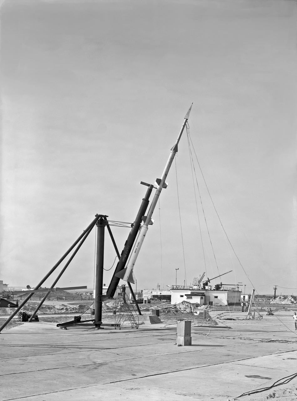
L5-19 (F40-2752) Model in Launch Position

Generic Transport Model (GTM) Roll angle positioning 12-Foot tunnel

Generic Transport Model (GTM) Roll angle positioning 12-Foot tunnel

Generic Transport Model (GTM) Roll angle positioning 12-Foot tunnel

Generic Transport Model (GTM) Roll angle positioning 12-Foot tunnel
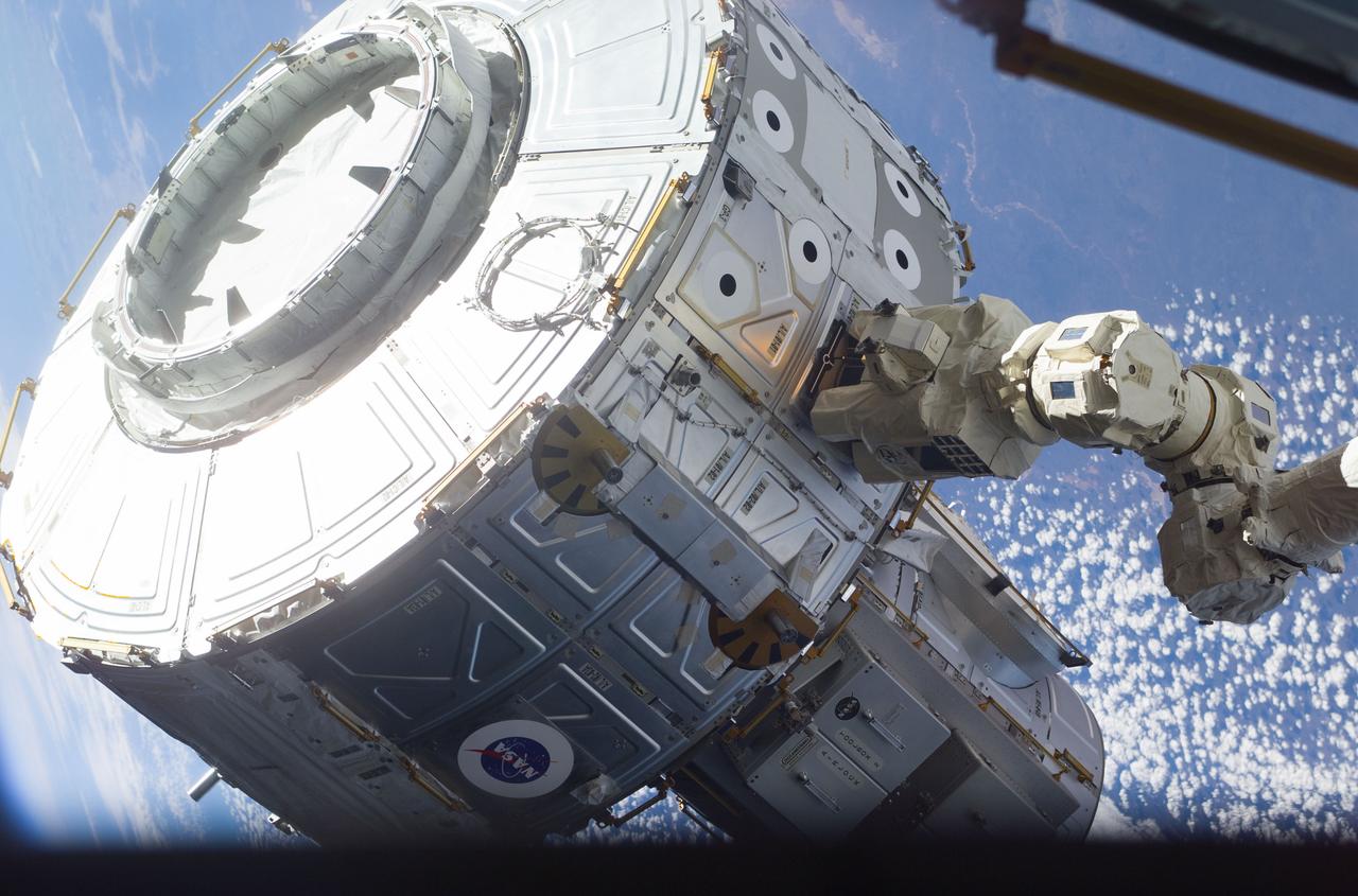
S104-E-5065 (15 July 2001) --- The newly-installed Candarm2, Space Station Remote Manipulator System (SSRMS), controlled by Susan J. Helms, Expedition Two flight engineer, maneuvers the Quest Airlock in the proper position to be mated onto the starboard side of Unity Node 1 during the first extravehicular activity (EVA) of the STS-104 mission. The Earth backdrops this image, exposed with a digital still camera.
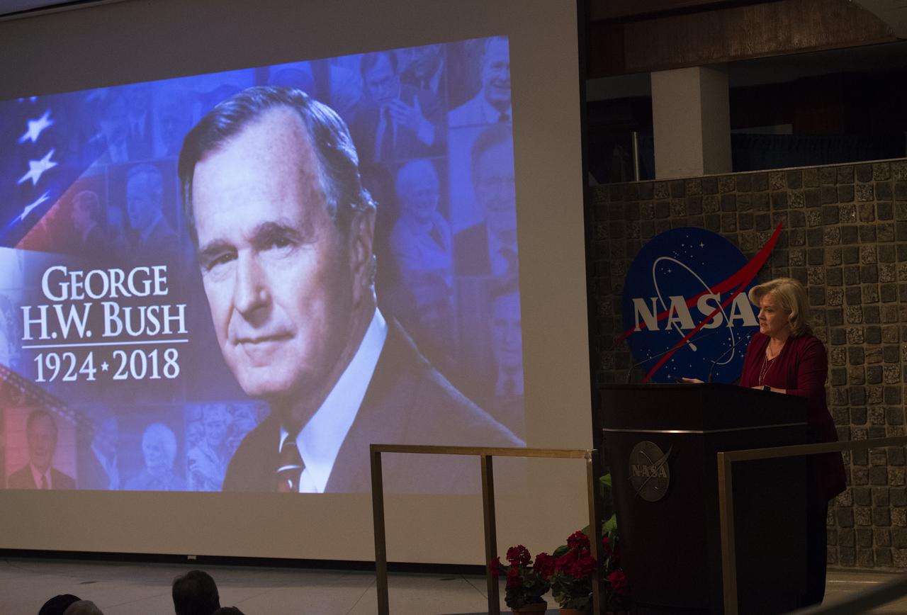
Jody Singer discusses Budget issues, the passing of President George H. W. Bush, and recent appointments to Marshall Leadership positions.
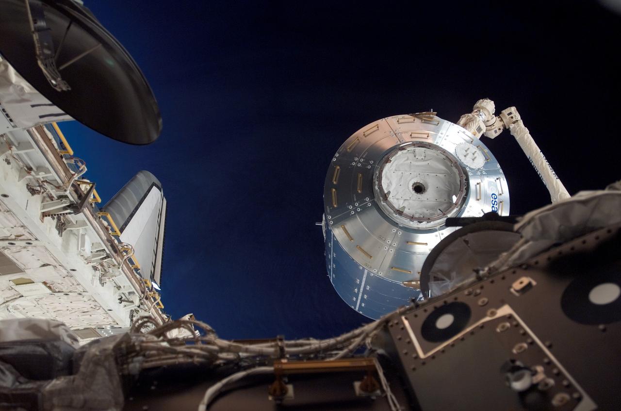
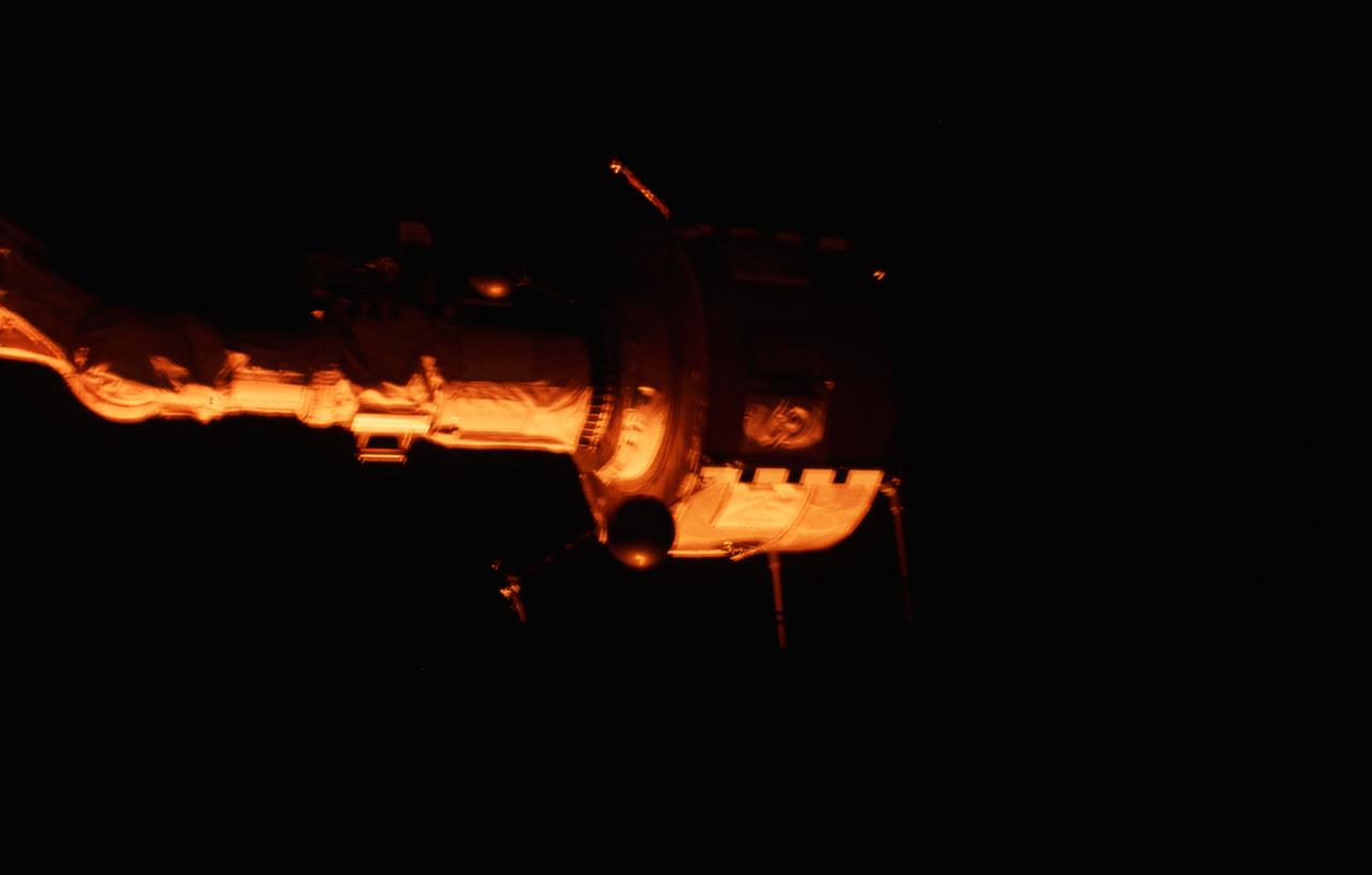
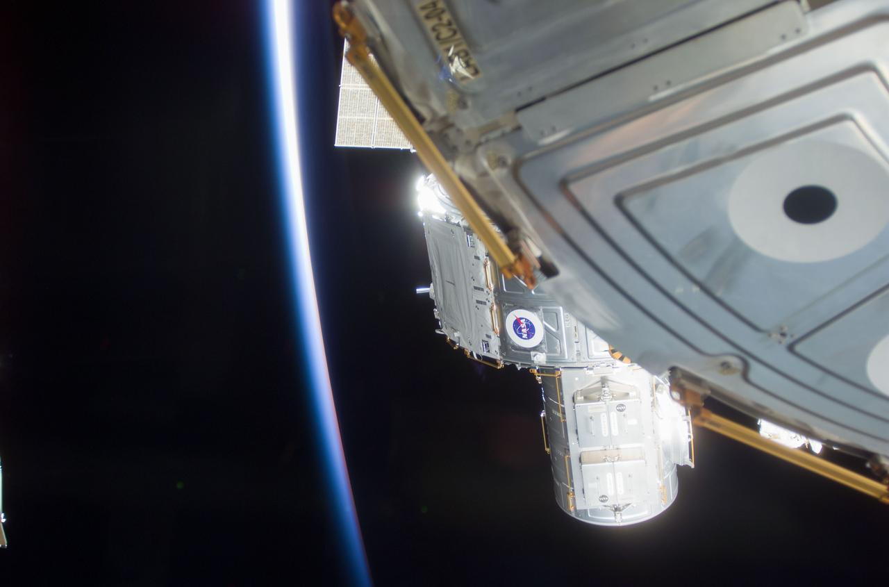
S122-E-007870 (11 Feb. 2008) --- In the grasp of the station's robotic Canadarm2, the Columbus laboratory is moved from its stowage position in Space Shuttle Atlantis' (STS-122) payload bay to the starboard side of the Harmony module of the International Space Station.
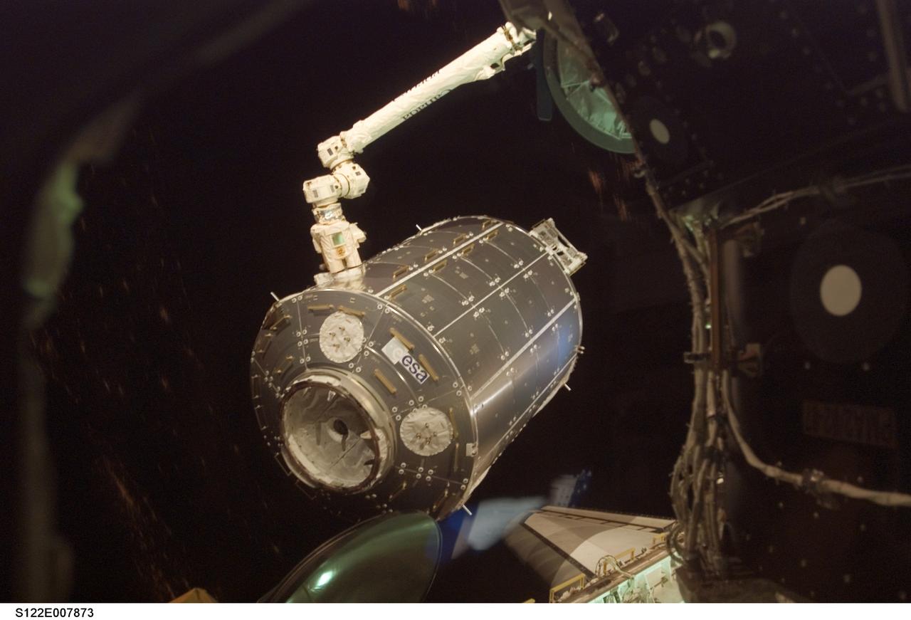
S122-E-007873 (11 Feb. 2008) --- Photographed through a window on the International Space Station, the station's robotic Canadarm2 moves the Columbus laboratory from its stowage position in Space Shuttle Atlantis' (STS-122) payload bay to the starboard side of the Harmony module.
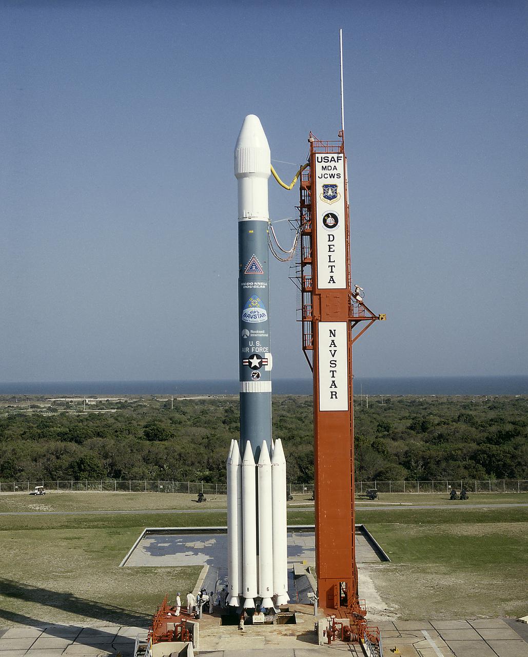
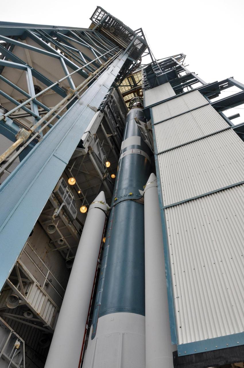
The Air Force Delta II vehicle sits poised on Complex 17A at the Cape Canaveral Air Station, ready to carry the 19th NAVSTAR Global Positioning System Satellite into orbit. A secondary NASA experiment, the Small Expendable Deployer System (SEDS), will also be deployed.
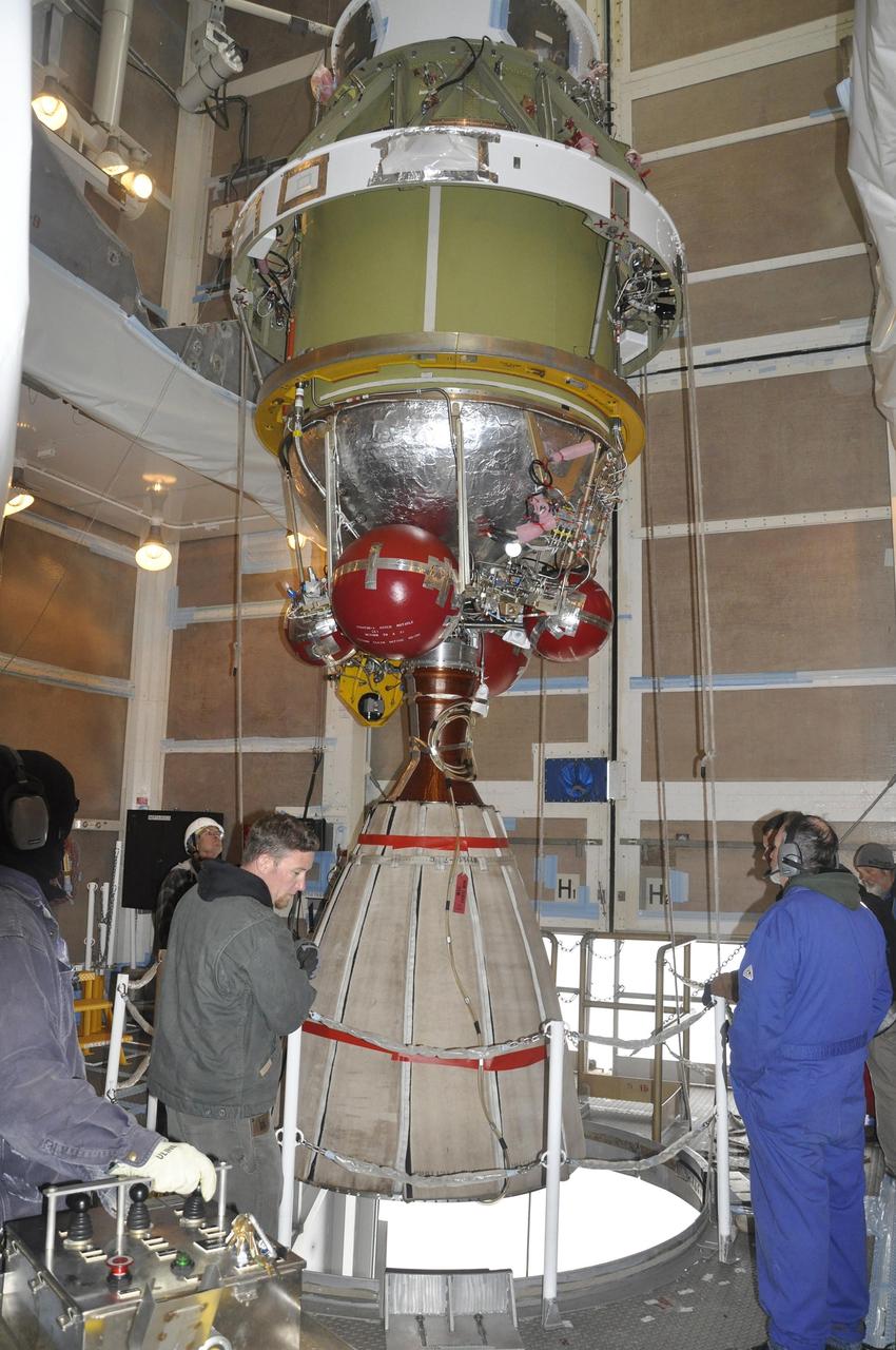
Workers monitor the Delta II second stage for NASA OCO-2, as it is lifted into position for mating with the rocket first stage in the mobile service tower at Space Launch Complex 2 on Vandenberg Air Force Base in California.
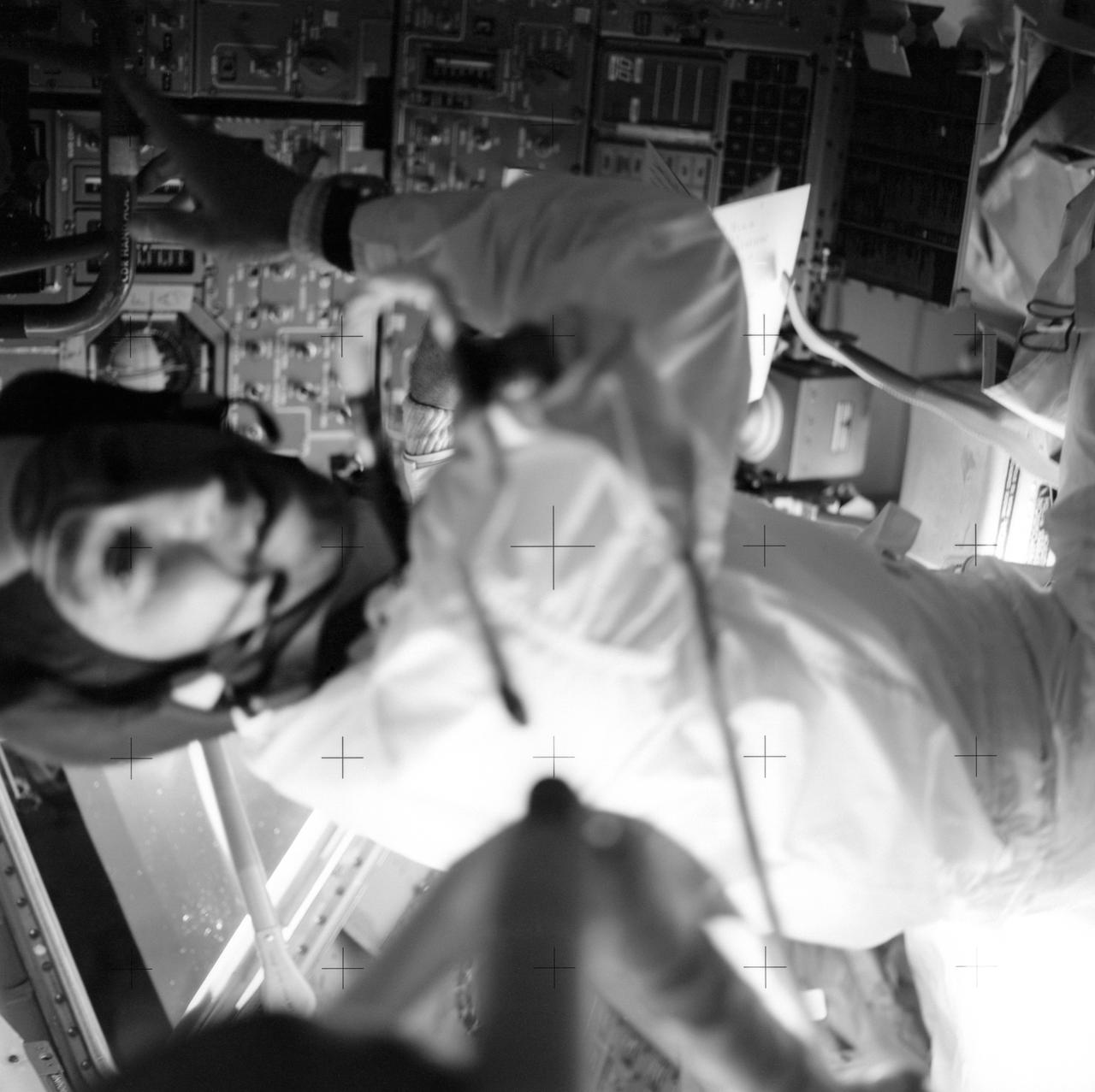
AS13-59-8484 (April 1970) --- Astronaut James A. Lovell Jr., commander, is pictured at his position in the Lunar Module (LM). The Apollo 13 crew of astronauts Lovell; John L. Swigert Jr., command module pilot; and Fred W. Haise Jr., lunar module pilot, relied on the LM as a "lifeboat". The dependence on the LM was caused by an apparent explosion of oxygen tank number two in the Service Module (SM). The LM was jettisoned just prior to Earth re-entry by the Command Module (CM).
STS003-21-080 (22-30 March 1982) --- Plasma Diagnostics Package (PDP) grappled by remote manipulator system (RMS) end effector is positioned above payload bay (PLB) at sunrise. Photo credit: NASA

Real-time data collected by the Global Differential Global Positioning System network, operated by NASA's Jet Propulsion Laboratory, shows the atmospheric signature of the Hunga Tonga Hunga Ha'apai volcanic eruption in Tonga on Jan. 15, 2022. The data is a measure of the density of electrons (known as total electron content units, or TECU) in the ionosphere – the outermost layer of the atmosphere, which starts between 50 and 56 miles (80 to 90 kilometers) above Earth's surface. Navigation radio signals, like those received by location sensors on smartphones, are broadcast by global navigation satellite systems (GNSS) and experience delays when passing through the ionosphere. The extent of the delay depends on the density of electrons within the path of the GNSS signal in this atmospheric layer. When an explosive event such as a volcanic eruption or large earthquake injects energy into the atmosphere, the pressure waves from that event change the electron density in the ionosphere. These perturbations show up as tiny changes to the delays that GNSS radio signals usually experience as they pass through the atmosphere. The vertical red line in the data plot indicates the time of the eruption. The horizontal squiggles show electron density profiles picked up in the signals of four GNSS constellations, or groups of satellites: GPS, GLONASS, Galileo, and BeiDou. The slanted dashed and dotted lines indicate the velocity of waves. https://photojournal.jpl.nasa.gov/catalog/PIA24905
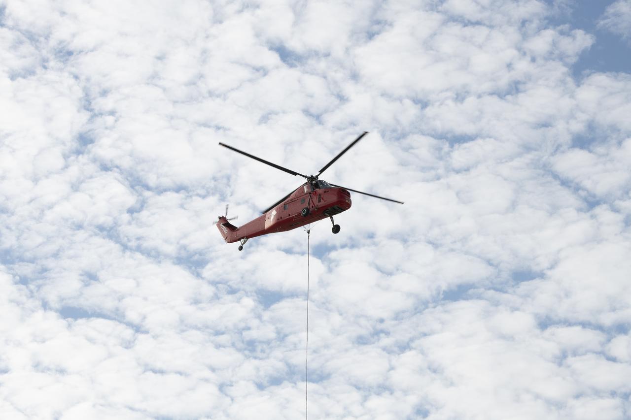
A helicopter is positioned to remove a rooftop pedestal from Building 4800 at NASA’s Armstrong Flight Research Center in Edwards, California, on Oct. 4, 2024. The pedestal was used since the 1950s to 2015 to house different telemetry dishes to collect data from research aircraft.

S95-10529 (3 May 1995) --- Inside the cavernous Vehicle Assembly Building (VAB), workers carry out the meticulous process of lifting the Orbiter Discovery from a horizontal to a vertical position. Once upright, Discovery will be transferred into a high bay for mating with the external tank and solid rocket booster assembly already mounted on the mobile launcher platform. Completing the assembly process takes about five working days. Discovery?s next destination is Launch Pad 39B, and final preparations for liftoff on mission STS-70 scheduled for June 1995.
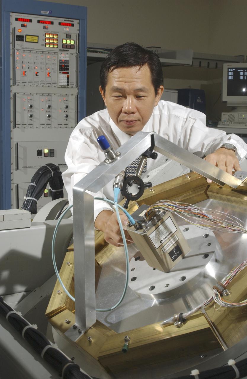
An array of components in a laboratory at NASA's Marshall Space Flight Center (MSFC) is being tested by the Flight Mechanics Office to develop an integrated navigation system for the second generation reusable launch vehicle. The laboratory is testing Global Positioning System (GPS) components, a satellite-based location and navigation system, and Inertial Navigation System (INS) components, sensors on a vehicle that determine angular velocity and linear acceleration at various points. The GPS and INS components work together to provide a space vehicle with guidance and navigation, like the push of the OnStar button in your car assists you with directions to a specific address. The integration will enable the vehicle operating system to track where the vehicle is in space and define its trajectory. The use of INS components for navigation is not new to space technology. The Space Shuttle currently uses them. However, the Space Launch Initiative is expanding the technology to integrate GPS and INS components to allow the vehicle to better define its position and more accurately determine vehicle acceleration and velocity. This advanced technology will lower operational costs and enhance the safety of reusable launch vehicles by providing a more comprehensive navigation system with greater capabilities. In this photograph, Dr. Jason Chuang of MSFC inspects an INS component in the laboratory.
ISS012-E-12909 (20 Dec. 2005) --- Astronaut William S. (Bill) McArthur Jr., Expedition 12 commander and NASA space station science officer, prepares the Capillary Flow Experiment (CFE) for video documentation. The CFE was positioned on the Maintenance Work Area in the Destiny laboratory of the International Space Station.
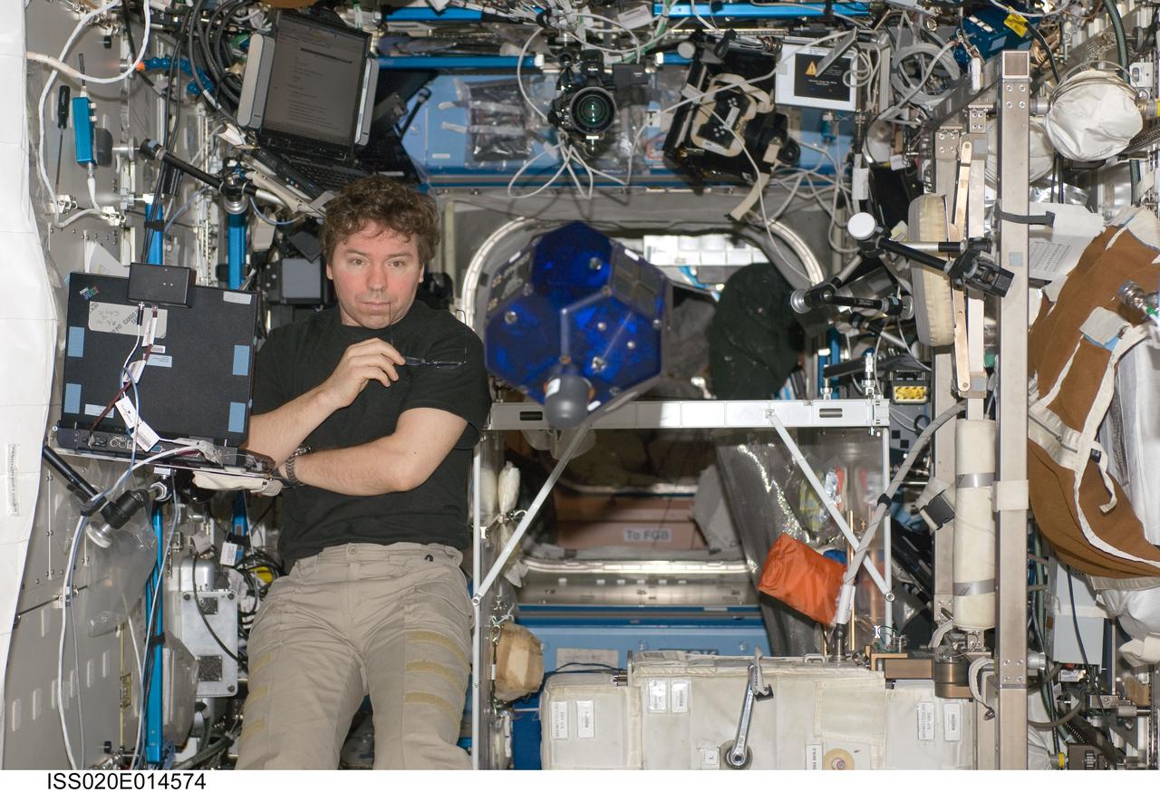
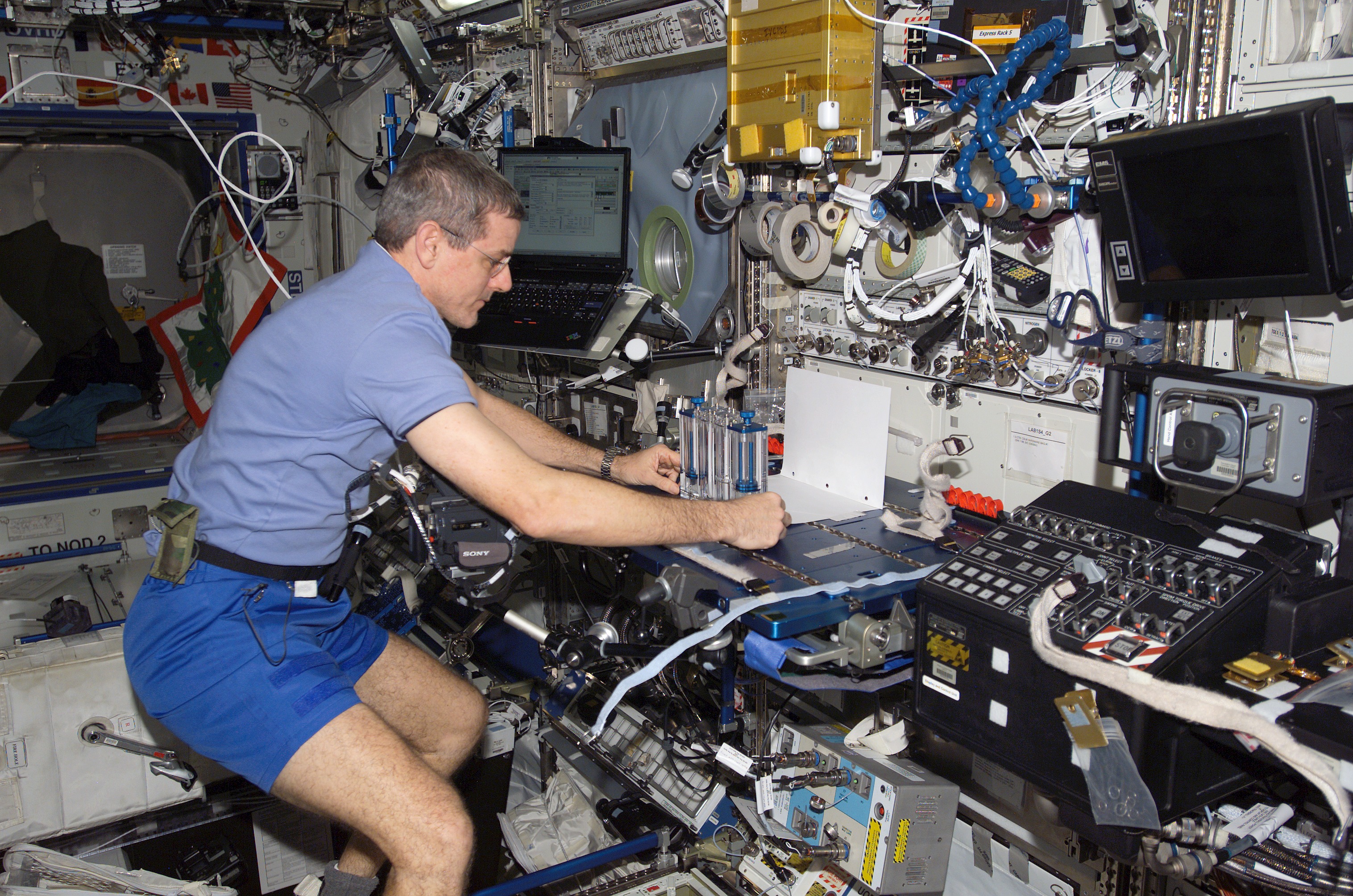
ISS020-E-014574 (26 June 2009) --- NASA astronaut Michael Barratt, Expedition 20 flight engineer, does a check of the Synchronized Position Hold, Engage, Reorient, Experimental Satellites (SPHERES) Beacon / Beacon Tester in the Destiny laboratory of the International Space Station.
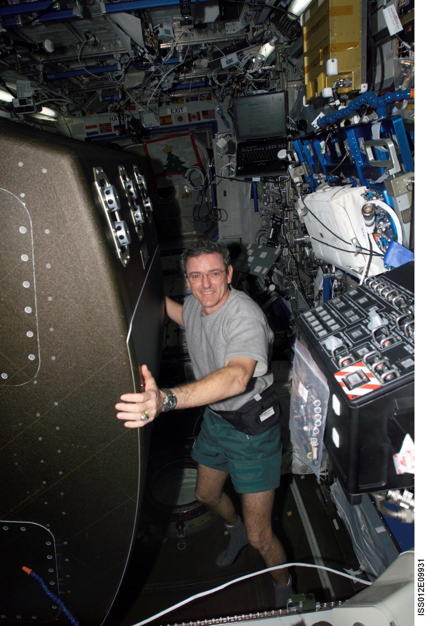
ISS012-E-09931 (1 December 2005) --- Astronaut William S. (Bill) McArthur Jr., Expedition 12 commander and NASA space station science officer, rotates the Crew Health Care System (CHeCS) rack back into position after cleaning the Avionics Air Assembly fan in the Destiny laboratory of the International Space Station.
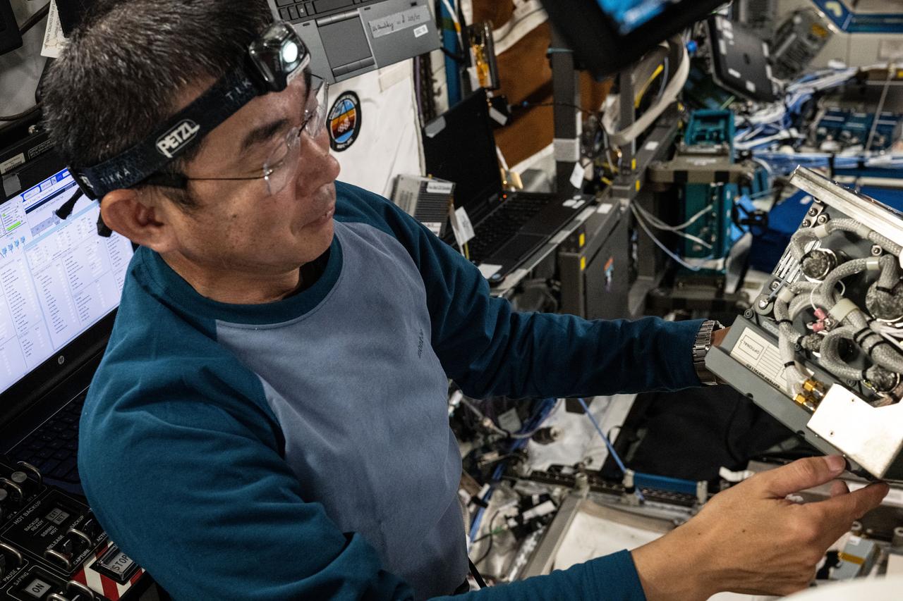
iss073e0511308 (Aug. 19, 2025) --- JAXA (Japan Aerospace Exploration Agency) astronaut and Expedition 73 Flight Engineer Kimiya Yui checks out a Global Positioning Satellite receiver during maintenance aboard the International Space Station's Destiny laboratory module.

NASA Deputy Administrator Pam Melroy gives opening remarks at the 25th meeting of the Space-Based Positioning, Navigation, and Timing National Advisory Board, Thursday, Dec. 9, 2021, at the Sheraton Pentagon City Hotel in Arlington, Va. Photo Credit: (NASA/Aubrey Gemignani)

NASA Deputy Administrator Pam Melroy gives opening remarks at the 25th meeting of the Space-Based Positioning, Navigation, and Timing National Advisory Board, Thursday, Dec. 9, 2021, at the Sheraton Pentagon City Hotel in Arlington, Va. Photo Credit: (NASA/Aubrey Gemignani)

NASA Deputy Administrator Pam Melroy gives opening remarks at the 25th meeting of the Space-Based Positioning, Navigation, and Timing National Advisory Board, Thursday, Dec. 9, 2021, at the Sheraton Pentagon City Hotel in Arlington, Va. Photo Credit: (NASA/Aubrey Gemignani)

NASA Deputy Administrator Pam Melroy gives opening remarks at the 25th meeting of the Space-Based Positioning, Navigation, and Timing National Advisory Board, Thursday, Dec. 9, 2021, at the Sheraton Pentagon City Hotel in Arlington, Va. Photo Credit: (NASA/Aubrey Gemignani)

NASA Deputy Administrator Pam Melroy gives opening remarks at the 25th meeting of the Space-Based Positioning, Navigation, and Timing National Advisory Board, Thursday, Dec. 9, 2021, at the Sheraton Pentagon City Hotel in Arlington, Va. Photo Credit: (NASA/Aubrey Gemignani)

NASA Deputy Administrator Pam Melroy gives opening remarks at the 25th meeting of the Space-Based Positioning, Navigation, and Timing National Advisory Board, Thursday, Dec. 9, 2021, at the Sheraton Pentagon City Hotel in Arlington, Va. Photo Credit: (NASA/Aubrey Gemignani)
The Delta II second stage for NASA Orbiting Carbon Observatory-2 mission, or OCO-2, is positioned atop the rocket first stage in the mobile service tower at Space Launch Complex 2 on Vandenberg Air Force Base in California.

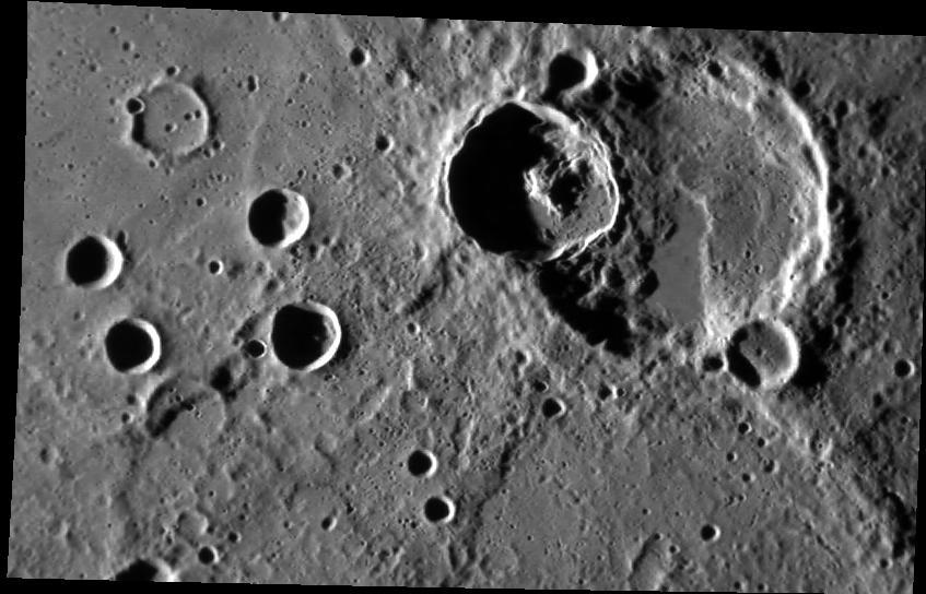
The great basin that interrupts the contours of this moon crescent identifies the satellite unmistakably as Mimas. The giant crater Herschel 130 kilometers, or 80 miles wide is this moon most obvious feature
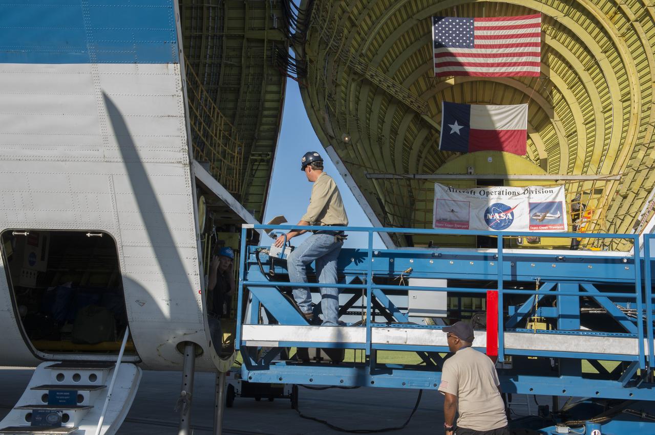
The platform which will be used to load the Orion stage adapter is being positioned in front of the cargo bay of NASA's Super Guppie aircraft. The adapter is being flown to Denver, Colorado for further testing.
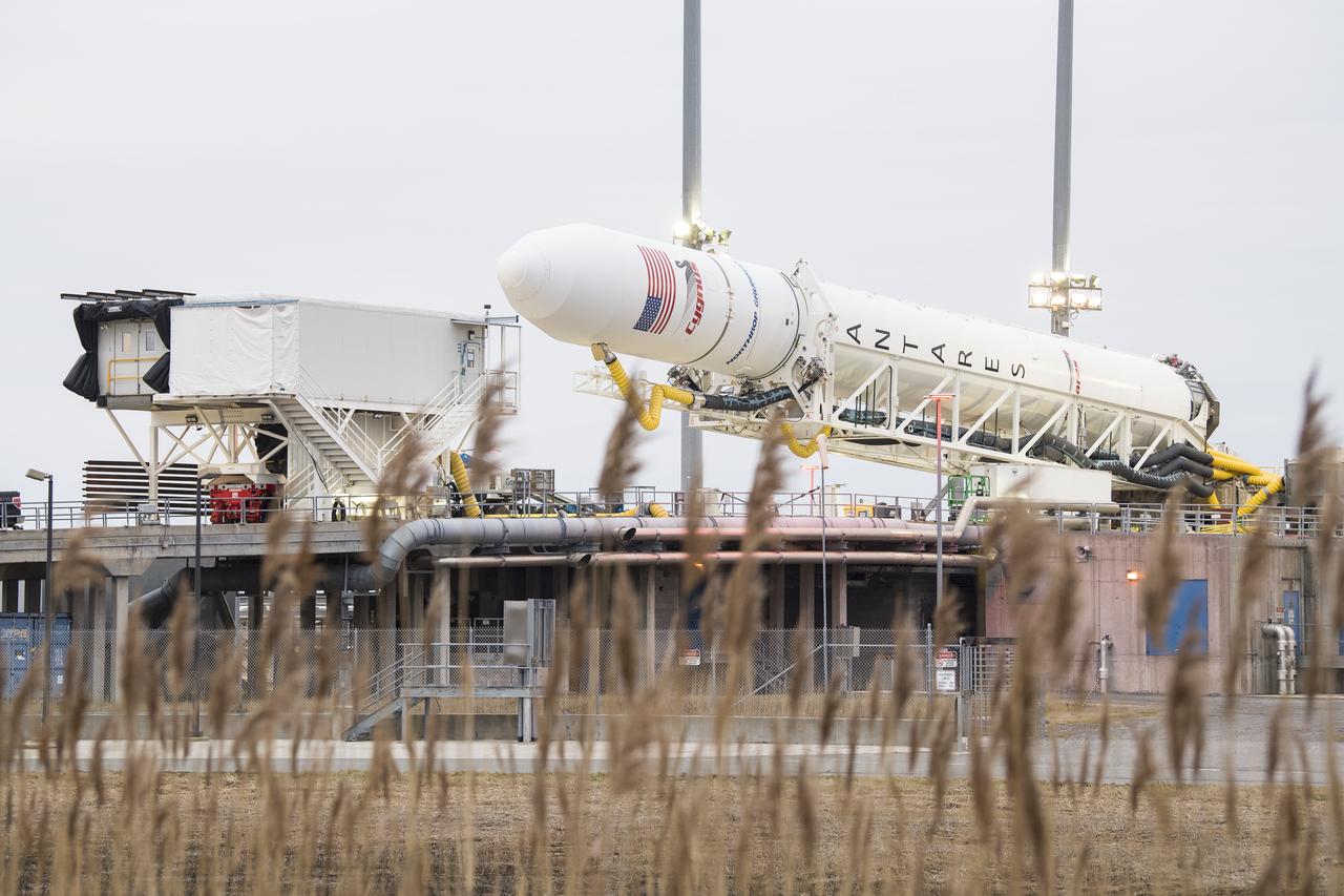
The Northrop Grumman Antares rocket is lowered into a horizontal position to refresh and reload the final cargo into the Cygnus resupply spacecraft, Wednesday, Feb. 12, 2020, at launch Pad-0A of NASA's Wallops Flight Facility in Virginia. Northrop Grumman’s 13th contracted cargo resupply mission with NASA to the International Space Station will deliver more than 7,500 pounds of science and research, crew supplies and vehicle hardware to the orbital laboratory and its crew. Photo Credit: (NASA/Aubrey Gemignani)
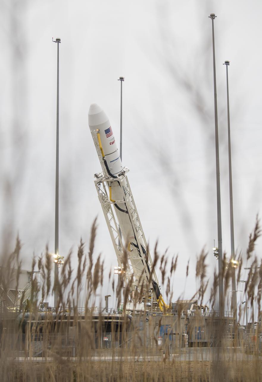
The Northrop Grumman Antares rocket is lowered into a horizontal position to refresh and reload the final cargo into the Cygnus resupply spacecraft, Wednesday, Feb. 12, 2020, at launch Pad-0A of NASA's Wallops Flight Facility in Virginia. Northrop Grumman’s 13th contracted cargo resupply mission with NASA to the International Space Station will deliver more than 7,500 pounds of science and research, crew supplies and vehicle hardware to the orbital laboratory and its crew. Photo Credit: (NASA/Aubrey Gemignani)
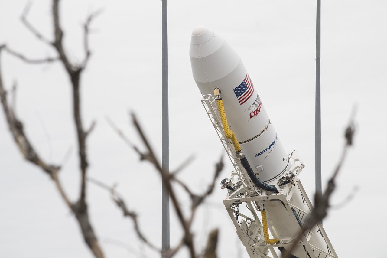
The Cygnus resupply spacecraft is seen atop the Northrop Grumman Antares rocket as it is lowered into a horizontal position to refresh and reload the final cargo, Wednesday, Feb. 12, 2020, at launch Pad-0A of NASA's Wallops Flight Facility in Virginia. Northrop Grumman’s 13th contracted cargo resupply mission with NASA to the International Space Station will deliver more than 7,500 pounds of science and research, crew supplies and vehicle hardware to the orbital laboratory and its crew. Photo Credit: (NASA/Aubrey Gemignani)
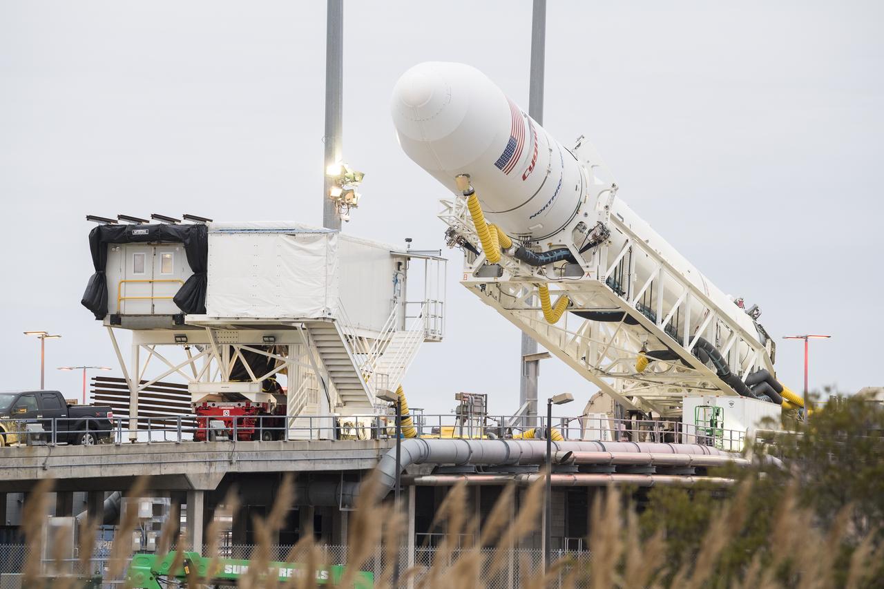
The Northrop Grumman Antares rocket is lowered into a horizontal position to refresh and reload the final cargo into the Cygnus resupply spacecraft, Wednesday, Feb. 12, 2020, at launch Pad-0A of NASA's Wallops Flight Facility in Virginia. Northrop Grumman’s 13th contracted cargo resupply mission with NASA to the International Space Station will deliver more than 7,500 pounds of science and research, crew supplies and vehicle hardware to the orbital laboratory and its crew. Photo Credit: (NASA/Aubrey Gemignani)
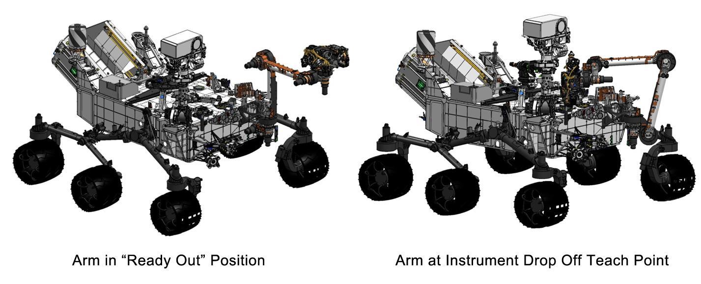
This engineering drawing shows the arm on NASA's Curiosity's rover in its "ready-for-action" position, or "ready out" as engineers say, in addition to the position it assumes to drop off samples. http://photojournal.jpl.nasa.gov/catalog/PIA16147
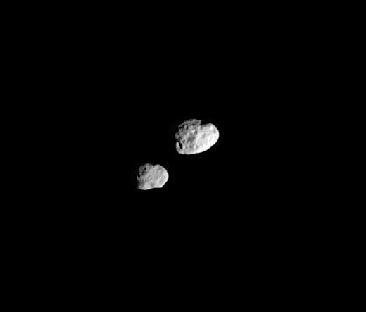
In their orbital ballet, Janus and Epimetheus swap positions every four years -- one moon moving closer to Saturn, the other moving farther away. The two recently changed positions
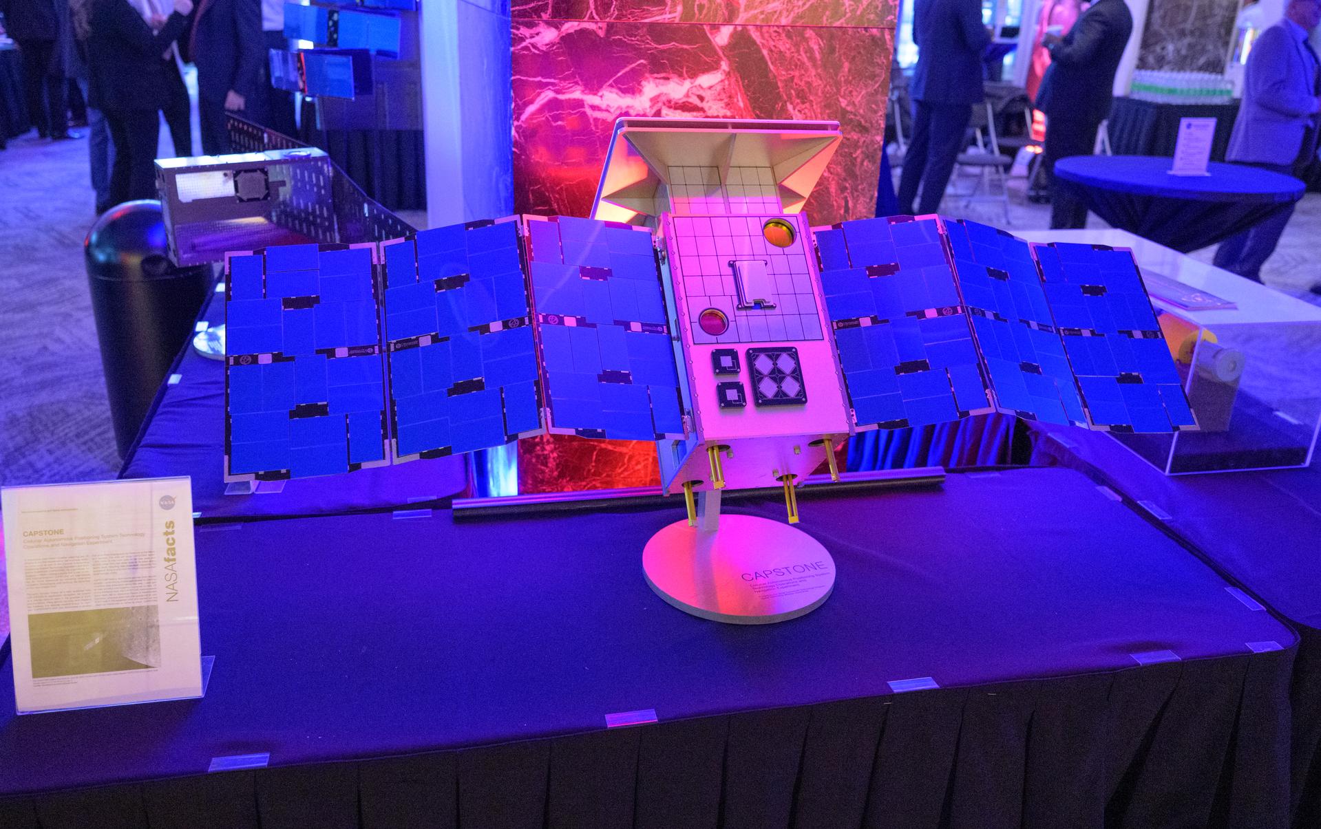
NASA Headquarters lobby is seen with a model of the Cislunar Autonomous Positioning System Technology Operations and Navigation Experiment (CAPSTONE) on display during a 2-day event where NASA outlined how the agency is executing President Donald J. Trump’s National Space Policy and accelerating preparations for America’s return to the surface of the Moon by 2028, Wednesday, March 25, 2026, at the Mary W. Jackson NASA Headquarters building in Washington. During the event NASA leadership provided updates on mission priorities, including sending the first astronauts to the lunar surface in more than 50 years, establishing the initial elements of a permanent lunar base, getting America underway in space on nuclear propulsion, and other objectives. Photo Credit: (NASA/Bill Ingalls)
STS035-28-006 (2-10 Dec 1990) --- STS-35 Astronomy Laboratory 1 (ASTRO-1) telescopes, in on-orbit operating position in the payload bay (PLB), are silhouetted against an reaction control system (RCS) right thruster firing. Three ultraviolet telescopes are mounted and precisely co-aligned on a common structure, called the cruciform, that is attached to the instrument pointing system (IPS). Here the IPS holds the telescopes in a position that is parallel to the Earth's limb below. Visible on the cruciform are the star tracker (S TRK) (silver cone at the top), the Ultraviolet Imaging Telescope (UIT) (behind S TRK), and the Hopkins Ultraviolet Telescope(HUT).
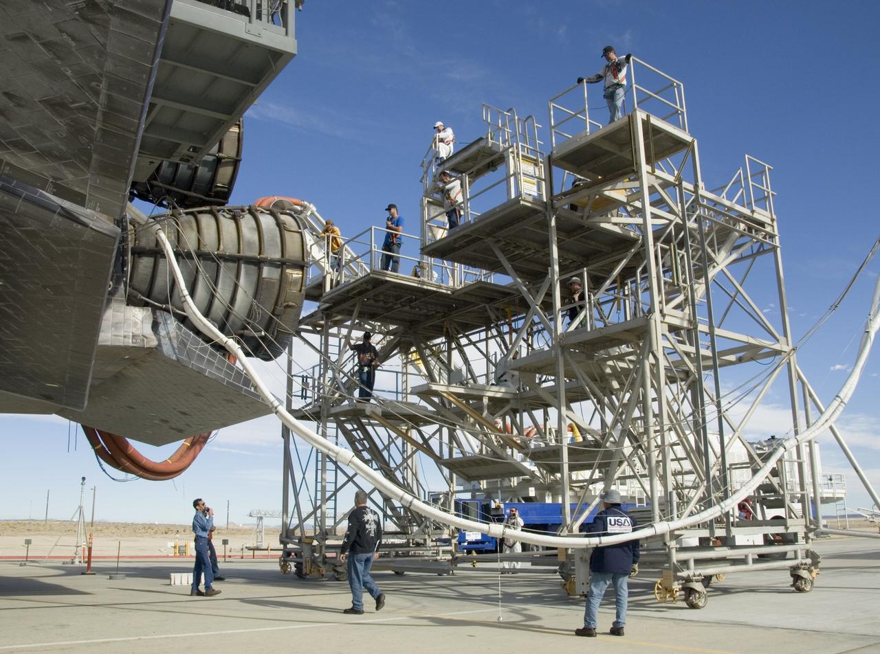
Technicians monitor the positioning of a large workstand as it is carefully moved into place around the main engines of the Space Shuttle Endeavour during deservicing and ferry flight preparations at NASA's Dryden Flight Research Center at Edwards Air Force Base.
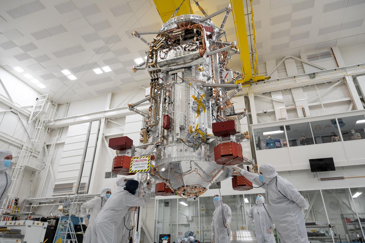
Engineers and technicians use a crane to lift the main body of NASA's Europa Clipper spacecraft and position it in the High Bay 1 clean room of the Spacecraft Assembly Facility at the agency's Jet Propulsion Laboratory in Southern California. Standing 10 feet (3 meters) high and 5 feet (1.5 meters) wide, the core will be the focus of attention as the spacecraft is assembled for its launch to Jupiter's moon Europa in October 2024. Europa Clipper will conduct nearly 50 flybys of the icy Jovian moon Europa, which scientists are confident harbors an internal ocean containing twice as much water as Earth's oceans combined. The moon may currently have conditions suitable for supporting life. The spacecraft's nine science instruments, plus a gravity science investigation, will gather data on the moon's atmosphere, surface, and interior – information that scientists will use to gauge the depth and salinity of the ocean, the thickness of the ice crust, and potential plumes that may be venting subsurface water into space. https://photojournal.jpl.nasa.gov/catalog/PIA25491
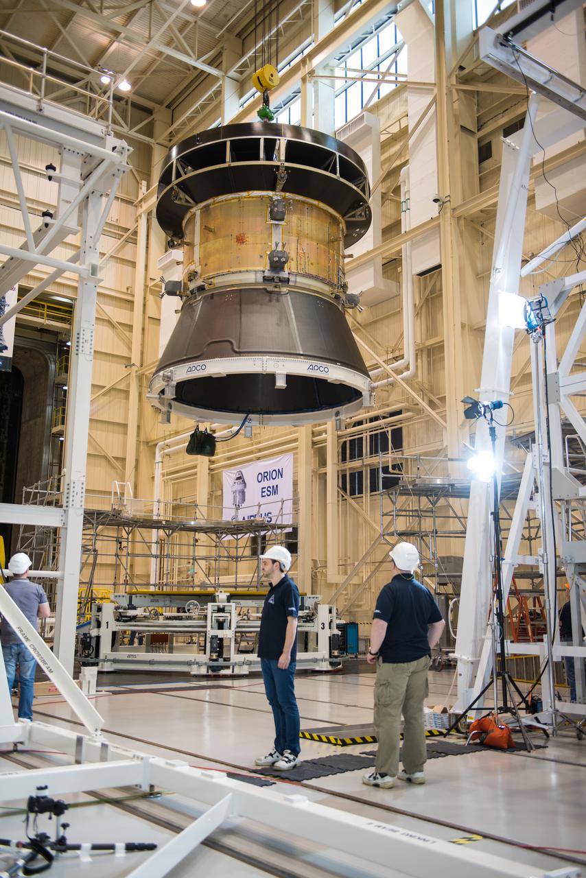
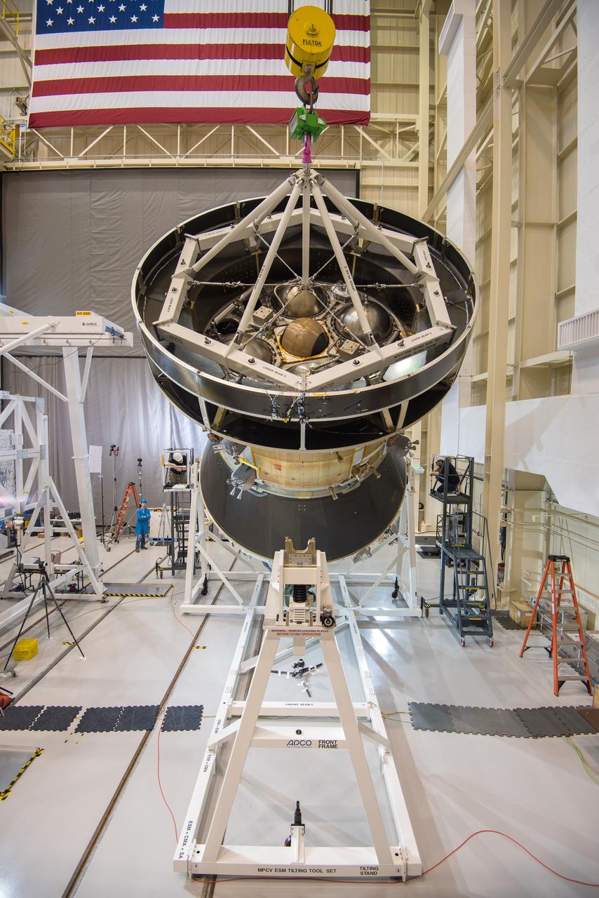
Engineers and technicians at NASA Glenn's Plum Brook Station in Sandusky, Ohio, are preparing for the first major test in the campaign to verify the structural integrity of Orion’s service module for Artemis I, the spacecraft’s first flight atop the agency’s Space Launch System (SLS) rocket. Orion’s service module, which will power and propel the vehicle and supply it with air and water, is being provided by ESA and built by Airbus Defence and Space. The solar array wing deployment test will verify that the qualification model wing unfurls as expected. On Saturday, Feb. 20, an international team of engineers and technicians lifted and tilted the service module test article -- which includes structural representations of the service module, crew module adapter, and spacecraft adapter -- to a 90 degree angle to position it for the deployment test of one of Orion’s four solar arrays. The next step in preparation for the test is attaching the solar array before the Feb. 29 deployment test. This is the first in a series of crucial tests to verify the service module’s structural integrity and ability to withstand the dynamic launch environment atop the SLS rocket.
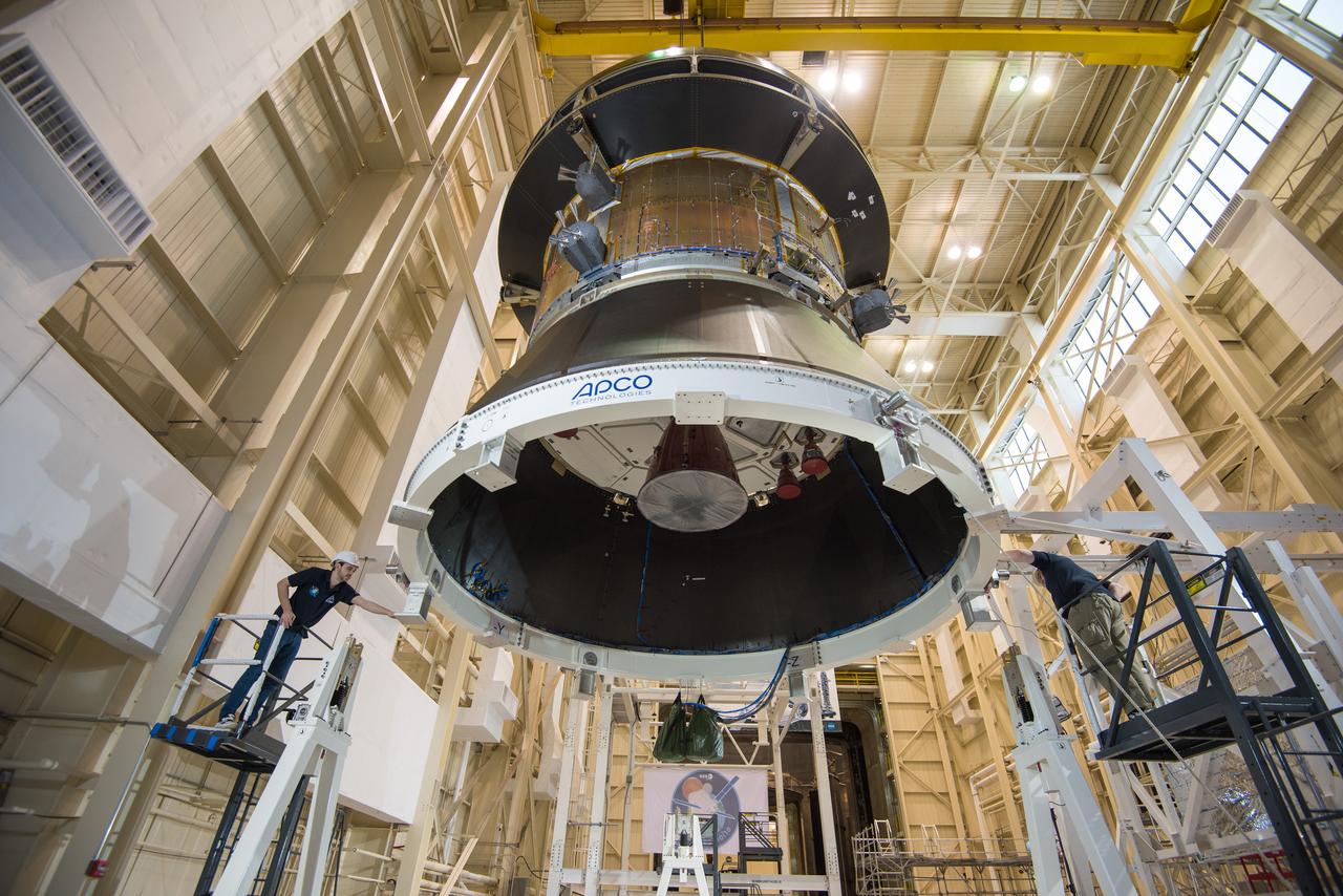
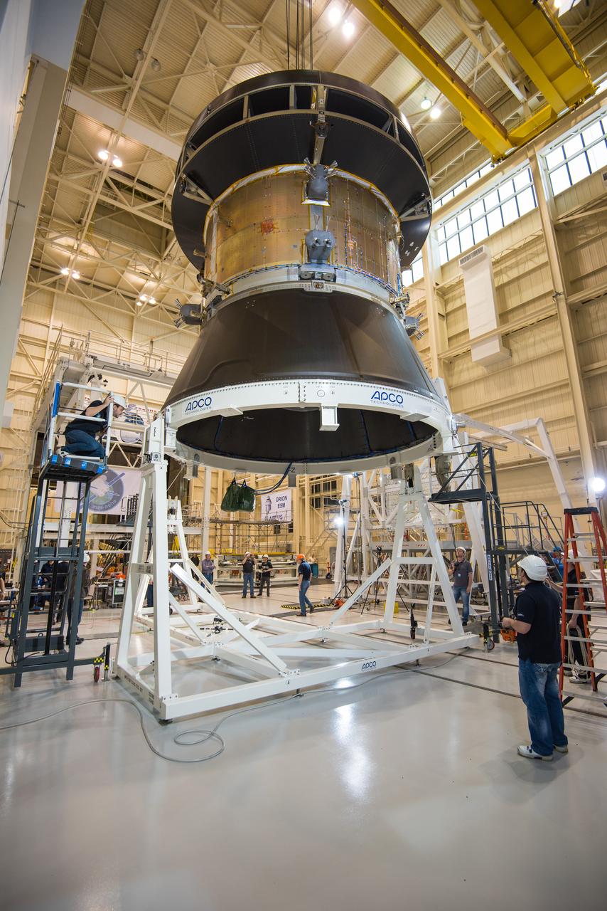
Engineers and technicians at NASA Glenn's Plum Brook Station in Sandusky, Ohio, are preparing for the first major test in the campaign to verify the structural integrity of Orion’s service module for Artemis I, the spacecraft’s first flight atop the agency’s Space Launch System (SLS) rocket. Orion’s service module, which will power and propel the vehicle and supply it with air and water, is being provided by ESA and built by Airbus Defence and Space. The solar array wing deployment test will verify that the qualification model wing unfurls as expected. On Saturday, Feb. 20, an international team of engineers and technicians lifted and tilted the service module test article -- which includes structural representations of the service module, crew module adapter, and spacecraft adapter -- to a 90 degree angle to position it for the deployment test of one of Orion’s four solar arrays. The next step in preparation for the test is attaching the solar array before the Feb. 29 deployment test. This is the first in a series of crucial tests to verify the service module’s structural integrity and ability to withstand the dynamic launch environment atop the SLS rocket.
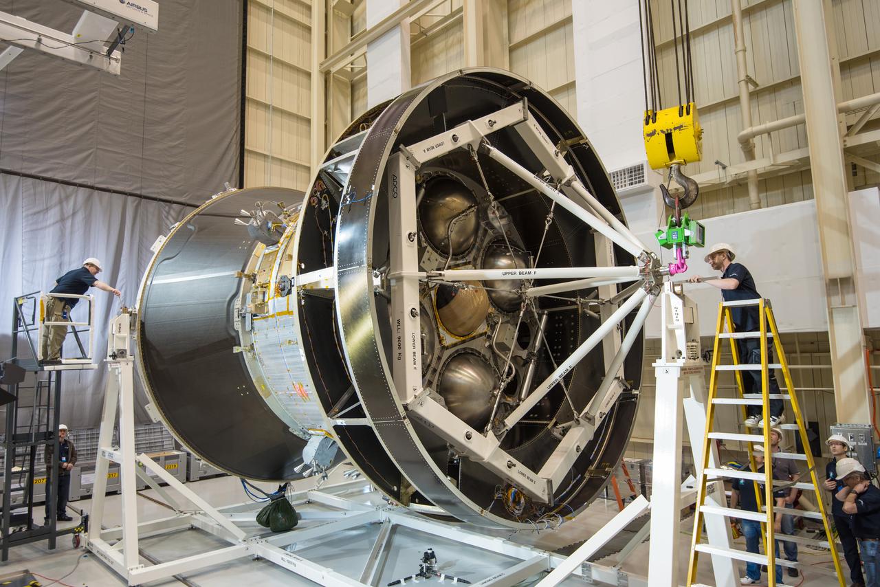
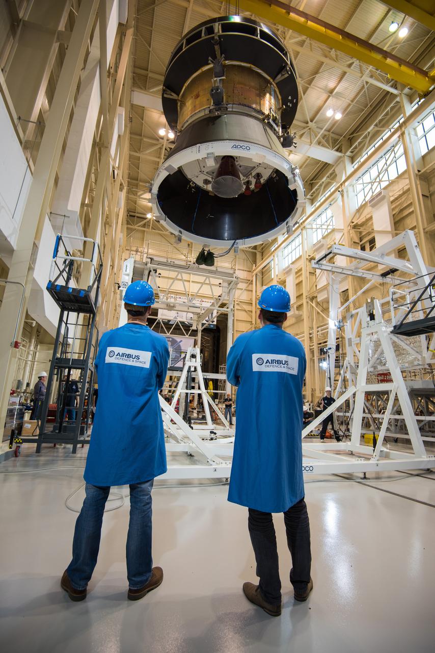
Engineers and technicians at NASA Glenn's Plum Brook Station in Sandusky, Ohio, are preparing for the first major test in the campaign to verify the structural integrity of Orion’s service module for Artemis I, the spacecraft’s first flight atop the agency’s Space Launch System (SLS) rocket. Orion’s service module, which will power and propel the vehicle and supply it with air and water, is being provided by ESA and built by Airbus Defence and Space. The solar array wing deployment test will verify that the qualification model wing unfurls as expected. On Saturday, Feb. 20, an international team of engineers and technicians lifted and tilted the service module test article -- which includes structural representations of the service module, crew module adapter, and spacecraft adapter -- to a 90 degree angle to position it for the deployment test of one of Orion’s four solar arrays. The next step in preparation for the test is attaching the solar array before the Feb. 29 deployment test. This is the first in a series of crucial tests to verify the service module’s structural integrity and ability to withstand the dynamic launch environment atop the SLS rocket.
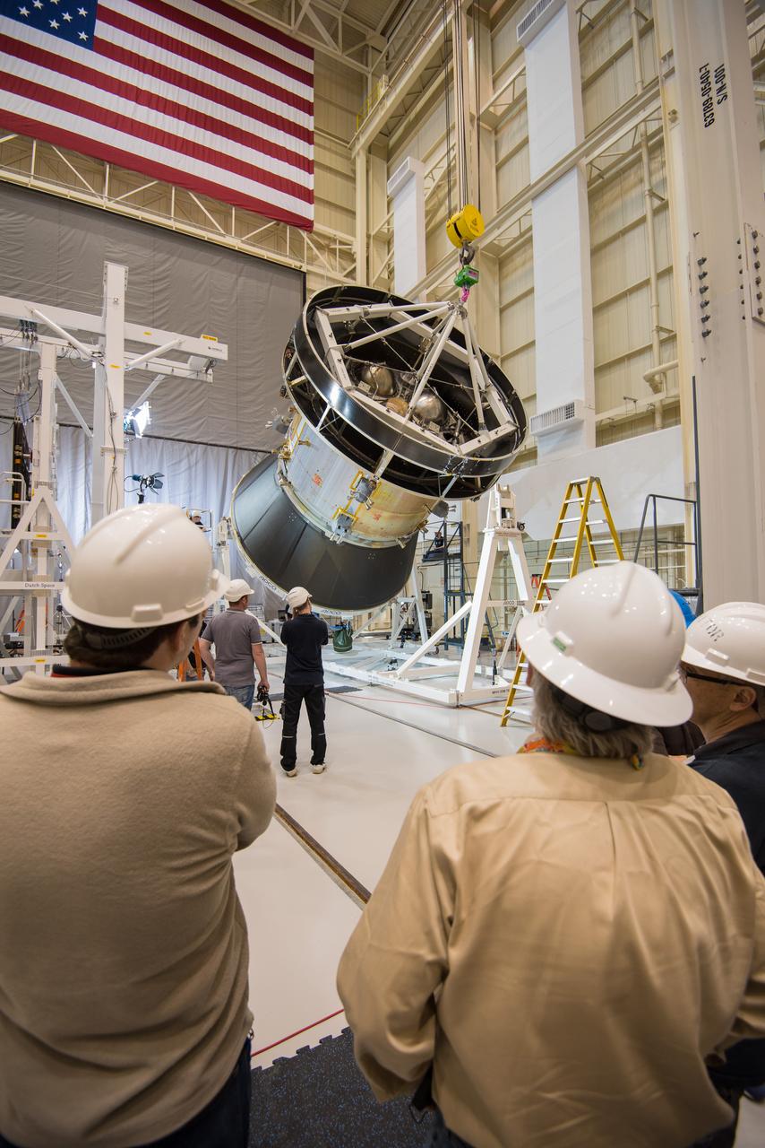
Engineers and technicians at NASA Glenn's Plum Brook Station in Sandusky, Ohio, are preparing for the first major test in the campaign to verify the structural integrity of Orion’s service module for Artemis I, the spacecraft’s first flight atop the agency’s Space Launch System (SLS) rocket. Orion’s service module, which will power and propel the vehicle and supply it with air and water, is being provided by ESA and built by Airbus Defence and Space. The solar array wing deployment test will verify that the qualification model wing unfurls as expected. On Saturday, Feb. 20, an international team of engineers and technicians lifted and tilted the service module test article -- which includes structural representations of the service module, crew module adapter, and spacecraft adapter -- to a 90 degree angle to position it for the deployment test of one of Orion’s four solar arrays. The next step in preparation for the test is attaching the solar array before the Feb. 29 deployment test. This is the first in a series of crucial tests to verify the service module’s structural integrity and ability to withstand the dynamic launch environment atop the SLS rocket.
Engineers and technicians at NASA Glenn's Plum Brook Station in Sandusky, Ohio, are preparing for the first major test in the campaign to verify the structural integrity of Orion’s service module for Artemis I, the spacecraft’s first flight atop the agency’s Space Launch System (SLS) rocket. Orion’s service module, which will power and propel the vehicle and supply it with air and water, is being provided by ESA and built by Airbus Defence and Space. The solar array wing deployment test will verify that the qualification model wing unfurls as expected. On Saturday, Feb. 20, an international team of engineers and technicians lifted and tilted the service module test article -- which includes structural representations of the service module, crew module adapter, and spacecraft adapter -- to a 90 degree angle to position it for the deployment test of one of Orion’s four solar arrays. The next step in preparation for the test is attaching the solar array before the Feb. 29 deployment test. This is the first in a series of crucial tests to verify the service module’s structural integrity and ability to withstand the dynamic launch environment atop the SLS rocket.
Engineers and technicians at NASA Glenn's Plum Brook Station in Sandusky, Ohio, are preparing for the first major test in the campaign to verify the structural integrity of Orion’s service module for Artemis I, the spacecraft’s first flight atop the agency’s Space Launch System (SLS) rocket. Orion’s service module, which will power and propel the vehicle and supply it with air and water, is being provided by ESA and built by Airbus Defence and Space. The solar array wing deployment test will verify that the qualification model wing unfurls as expected. On Saturday, Feb. 20, an international team of engineers and technicians lifted and tilted the service module test article -- which includes structural representations of the service module, crew module adapter, and spacecraft adapter -- to a 90 degree angle to position it for the deployment test of one of Orion’s four solar arrays. The next step in preparation for the test is attaching the solar array before the Feb. 29 deployment test. This is the first in a series of crucial tests to verify the service module’s structural integrity and ability to withstand the dynamic launch environment atop the SLS rocket.
Engineers and technicians at NASA Glenn's Plum Brook Station in Sandusky, Ohio, are preparing for the first major test in the campaign to verify the structural integrity of Orion’s service module for Artemis I, the spacecraft’s first flight atop the agency’s Space Launch System (SLS) rocket. Orion’s service module, which will power and propel the vehicle and supply it with air and water, is being provided by ESA and built by Airbus Defence and Space. The solar array wing deployment test will verify that the qualification model wing unfurls as expected. On Saturday, Feb. 20, an international team of engineers and technicians lifted and tilted the service module test article -- which includes structural representations of the service module, crew module adapter, and spacecraft adapter -- to a 90 degree angle to position it for the deployment test of one of Orion’s four solar arrays. The next step in preparation for the test is attaching the solar array before the Feb. 29 deployment test. This is the first in a series of crucial tests to verify the service module’s structural integrity and ability to withstand the dynamic launch environment atop the SLS rocket.

Engineers and technicians at NASA Glenn's Plum Brook Station in Sandusky, Ohio, are preparing for the first major test in the campaign to verify the structural integrity of Orion’s service module for Artemis I, the spacecraft’s first flight atop the agency’s Space Launch System (SLS) rocket. Orion’s service module, which will power and propel the vehicle and supply it with air and water, is being provided by ESA and built by Airbus Defence and Space. The solar array wing deployment test will verify that the qualification model wing unfurls as expected. On Saturday, Feb. 20, an international team of engineers and technicians lifted and tilted the service module test article -- which includes structural representations of the service module, crew module adapter, and spacecraft adapter -- to a 90 degree angle to position it for the deployment test of one of Orion’s four solar arrays. The next step in preparation for the test is attaching the solar array before the Feb. 29 deployment test. This is the first in a series of crucial tests to verify the service module’s structural integrity and ability to withstand the dynamic launch environment atop the SLS rocket.
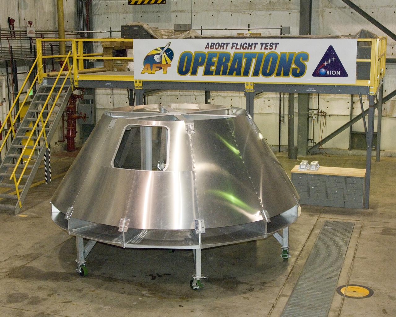
NASA Dryden's mockup Orion crew module is located in Dryden's Shuttle hangar, where abort flight test equipment is being positioned.
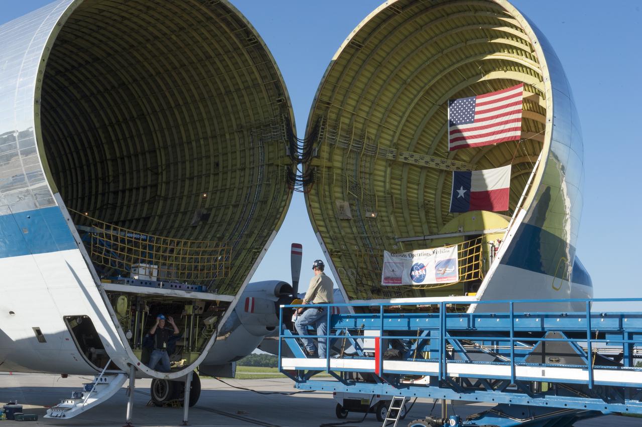
The platform which will be used to load the Orion stage adapter is shown being positioned in front of NASA's Super Guppie. After being tested at Marshall Space Flight Center the stage adapter will be flown to Denver, Colorado for further testing.
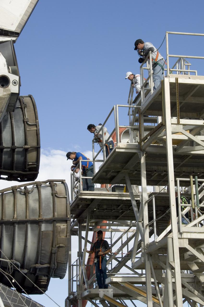
Technicians monitor the positioning of a large workstand as it is carefully moved into place around the main engine nozzles of Space Shuttle Endeavour during deservicing and ferry flight preparations at NASA's Dryden Flight Research Center at Edwards Air Force Base.
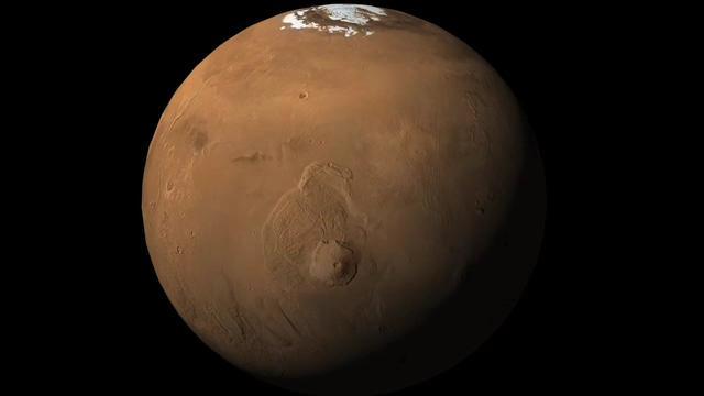
This image shows an orbital view sweeping upward from Olympus Mons, the tallest volcano in the solar system, to the location of NASA Phoenix Mars Lander in the northern polar reaches of Mars.

Mars Exploration Rover team members at NASA Jet Propulsion Laboratory, Pasadena, Calif., prepare an experiment on July 13, 2009, for assessing how a test rover moves when embedded in loose soil and commanded to drive backward with wheels turned.
S104-E-5071 (15 July 2001) --- As the sun sets behind the Earth's horizon, the Expedition Two and STS-104 crews continue to install the Quest Airlock onto the starboard side of Unity Node 1. Susan J. Helms, Expedition Two flight engineer, working in the Destiny U.S. Laboratory, maneuvered the Airlock into place with the Canadarm2, Space Station Remote Manipulator System (SSRMS), while being assisted by Michael L. Gernhardt and James F. Reilly, STS-104 mission specialists, during their first extravehicular activity (EVA).
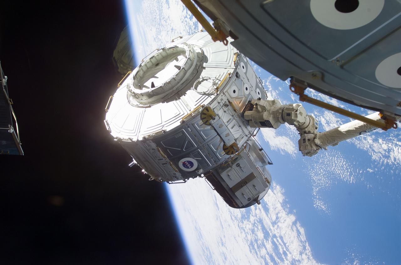
STS104-E-5068 (15 July 2001) --- Backdropped against a blue and white Earth, some 237 miles below, the Quest airlock is in the process of being installed onto the starboard side of Unity Node 1 of the International Space Station (ISS). Astronaut Susan J. Helms, Expedition Two flight engineer, used controls onboard the station to maneuver the Airlock into place with the Canadarm2 or Space Station Remote Manipulator System (SSRMS). This image was recorded with a digital still camera.
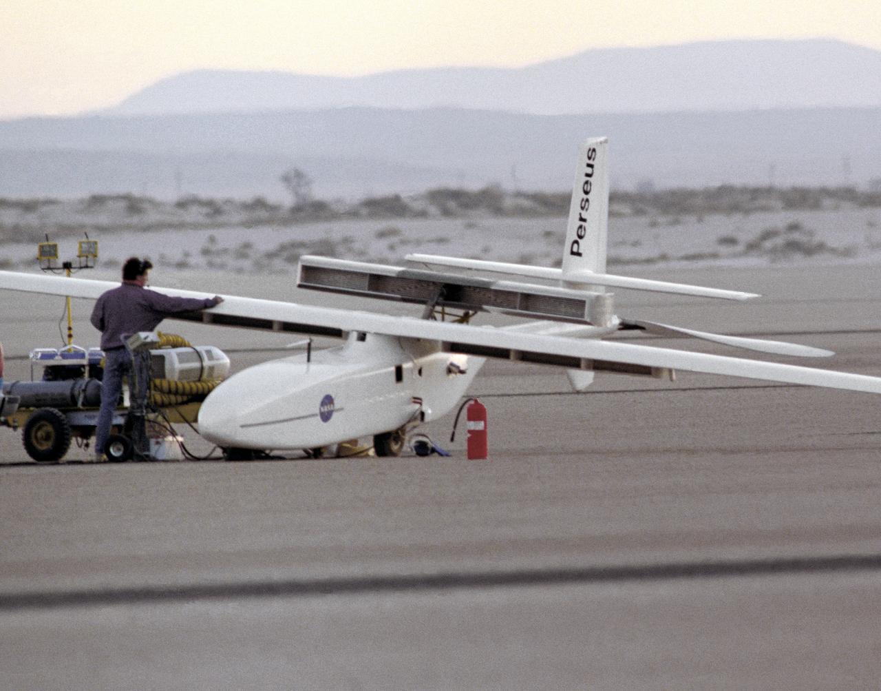
The Perseus A, a remotely-piloted, high-altitude research vehicle, is seen just after landing on Rogers Dry Lake at the Dryden Flight Research Center, Edwards, California. The Perseus A had a unique method of takeoff and landing. To make the aircraft as aerodynamic and lightweight as possible, designers gave it only two very small centerline wheels for landing. These wheels were very close to the fuselage, and therefore produced very little drag. However, since the fuselage sat so close to the ground, it was necessary to keep the large propeller at the rear of the aircraft locked in a horizontal position during takeoff. The aircraft was towed to about 700 feet in the air, where the engine was started and the aircraft began flying under its own power.
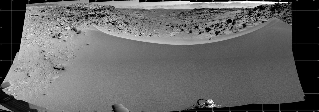
This mosaic of images from NASA Mars rover Curiosity shows the terrain to the west from the rover position on Jan. 30, 2014.
Technicians position NASA’s Juno spacecraft on a dolly prior to the start of a round of acoustical testing.
A pedestal carried by a helicopter is positioned for a gentle placement on the ground. The helicopter removed the pedestal from the rooftop of Building 4800 at NASA’s Armstrong Flight Research Center in Edwards, California, on Oct. 4, 2024. The pedestal was used since the 1950s to 2015 to house different telemetry dishes to collect data from research aircraft.
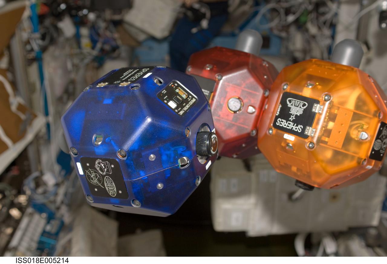
ISS018-E-005214 (26 Oct. 2008) --- This close-up view shows three bowling-ball-sized free-flying satellites called Synchronized Position Hold, Engage, Reorient, Experimental Satellites (SPHERES) in the Destiny laboratory of the International Space Station. SPHERES were designed to test control algorithms for spacecraft by performing autonomous rendezvous and docking maneuvers inside the station. The results are important for multi-body control and in designing constellation and array spacecraft configurations.
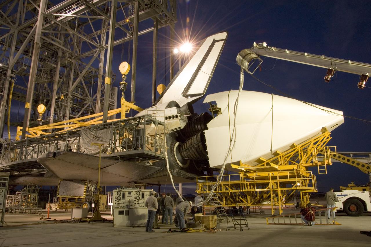
NASA technicians position the aerodynamic tailcone around the engine nozzles of the Space Shuttle Endeavour Dec. 7 in preparation for its ferry flight from NASA's Dryden Flight Research Center at Edwards Air Force Base back to the Kennedy Space Center in Florida.
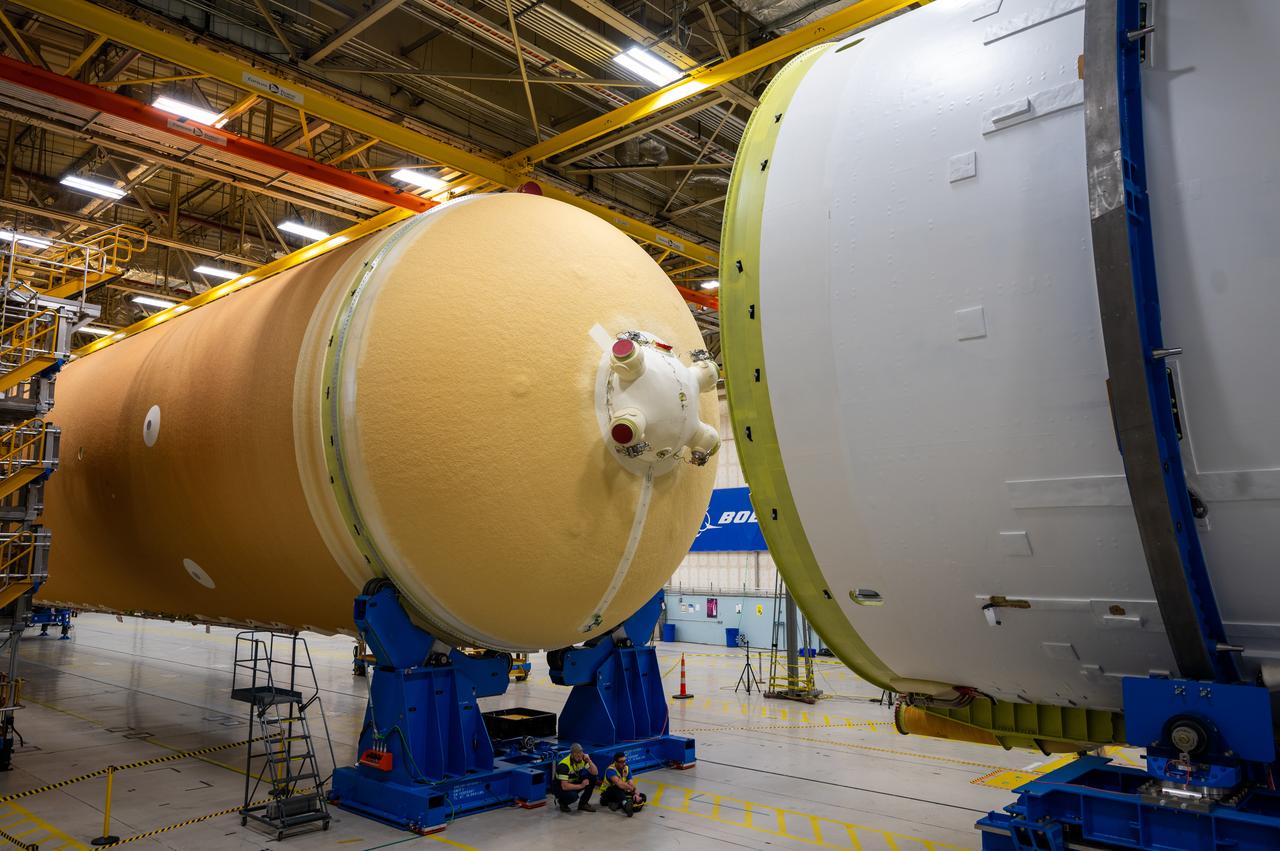
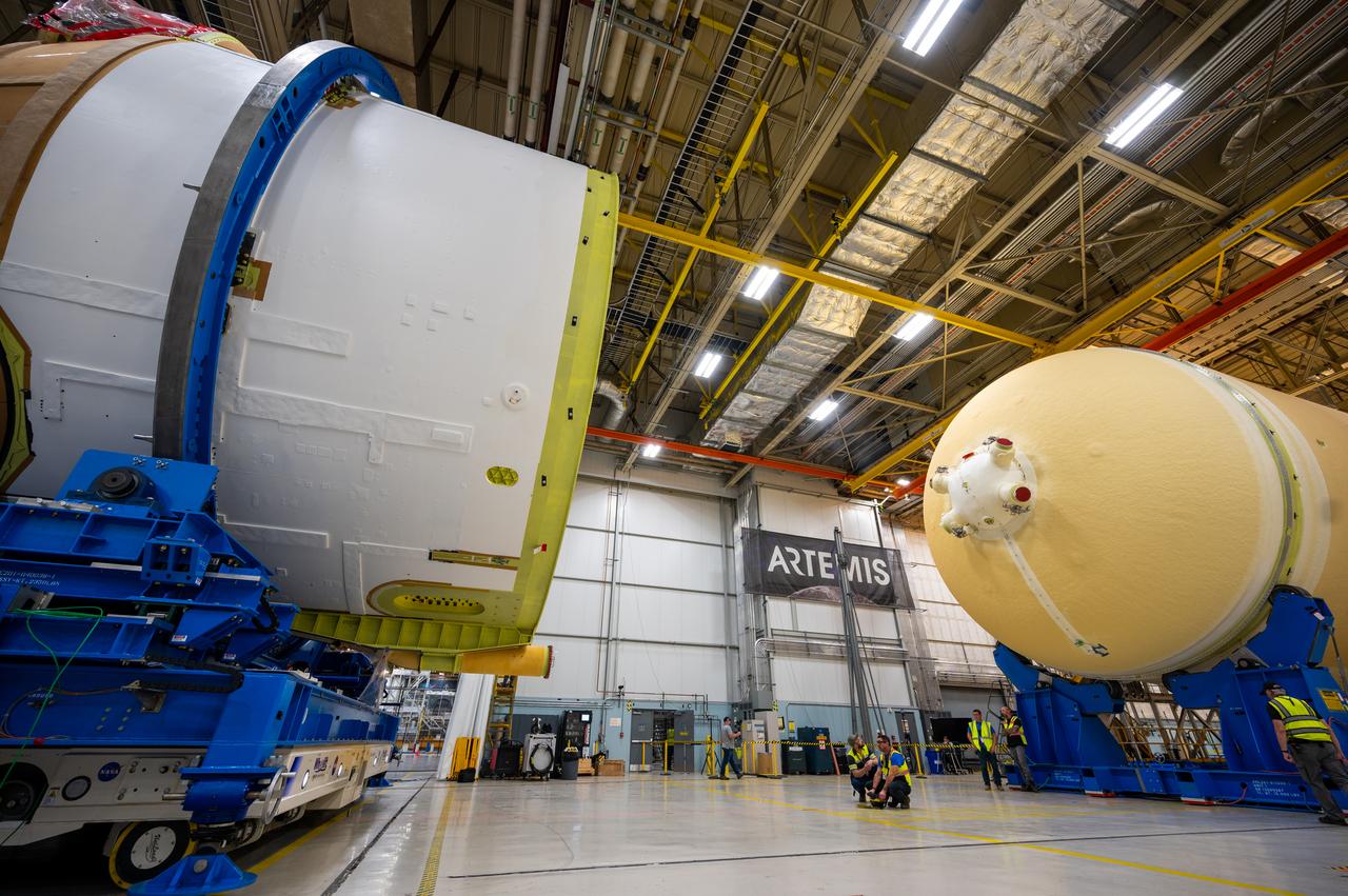
Technicians at NASA’s Michoud Assembly Facility in New Orleans moved the engine section of NASA’s Space Launch System (SLS) rocket for Artemis II, the first crewed mission to the Moon, into position for the final join of the core stage Feb. 22. The engine section is the bottom-most portion of the 212-foot-tall core stage. It is the last of five major elements that is needed to connect the stage into one major structure. In addition to its miles of cabling and hundreds of sensors, the engine section is a crucial attachment point for the four RS-25 engines and two solid rocket boosters that produce a combined 8.8 million pounds of thrust at liftoff and flight. During launch and flight, liquid propellants from the liquid hydrogen tank and liquid oxygen tanks are delivered through the engine section to the four RS-25 engines. The engine section also includes the avionics that help steer the engines after liftoff. Next, teams will join the engine section to the core stage for the second SLS rocket. After the join is complete, teams will begin to add each of the four RS-25 engines one by one to complete the stage. The completely assembled stage with its four RS-25 engines will be shipped to NASA’s Kennedy Space Center in Florida later this year. The SLS rocket is the only rocket capable of carrying astronauts in Orion around the Moon in a single mission.
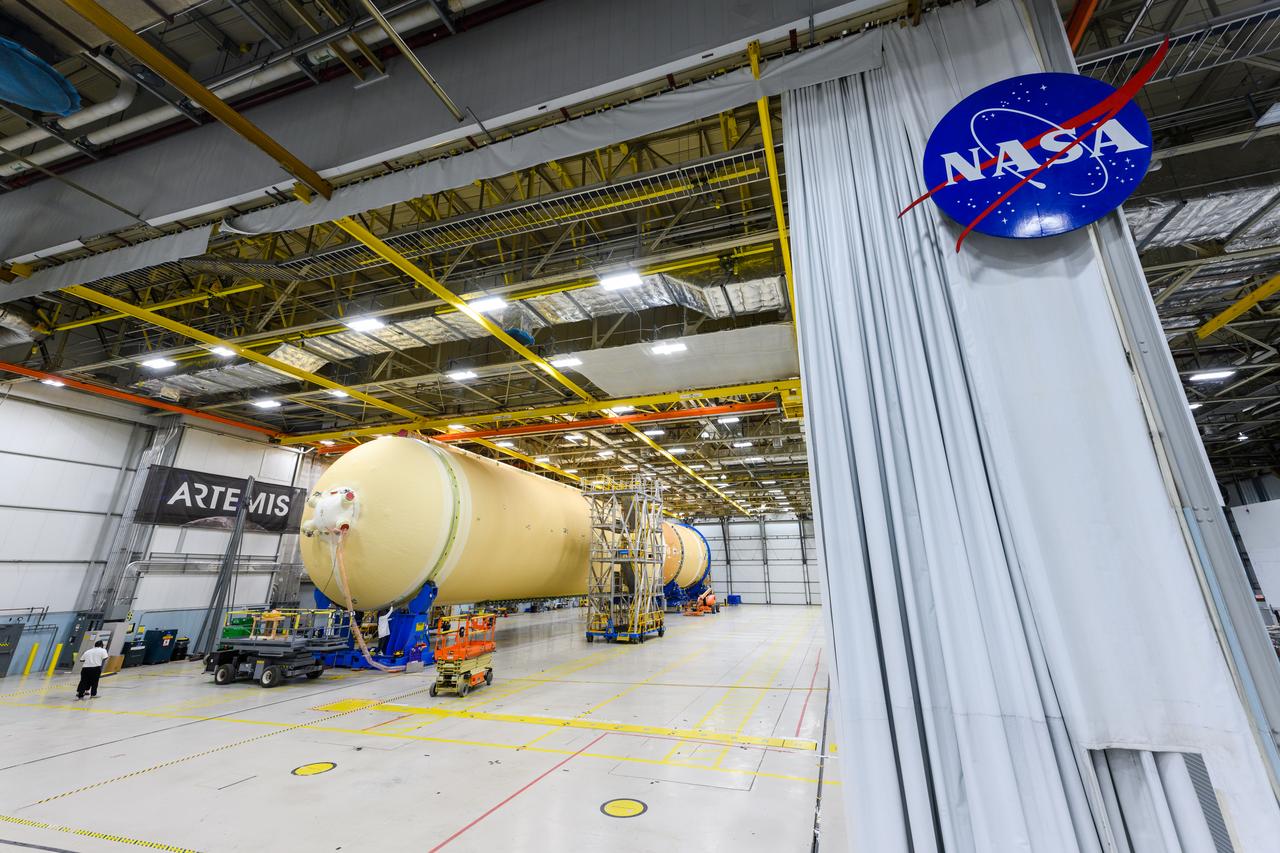
Technicians at NASA’s Michoud Assembly Facility in New Orleans moved the engine section of NASA’s Space Launch System (SLS) rocket for Artemis II, the first crewed mission to the Moon, into position for the final join of the core stage Feb. 22. The engine section is the bottom-most portion of the 212-foot-tall core stage. It is the last of five major elements that is needed to connect the stage into one major structure. In addition to its miles of cabling and hundreds of sensors, the engine section is a crucial attachment point for the four RS-25 engines and two solid rocket boosters that produce a combined 8.8 million pounds of thrust at liftoff and flight. During launch and flight, liquid propellants from the liquid hydrogen tank and liquid oxygen tanks are delivered through the engine section to the four RS-25 engines. The engine section also includes the avionics that help steer the engines after liftoff. Next, teams will join the engine section to the core stage for the second SLS rocket. After the join is complete, teams will begin to add each of the four RS-25 engines one by one to complete the stage. The completely assembled stage with its four RS-25 engines will be shipped to NASA’s Kennedy Space Center in Florida later this year. The SLS rocket is the only rocket capable of carrying astronauts in Orion around the Moon in a single mission.
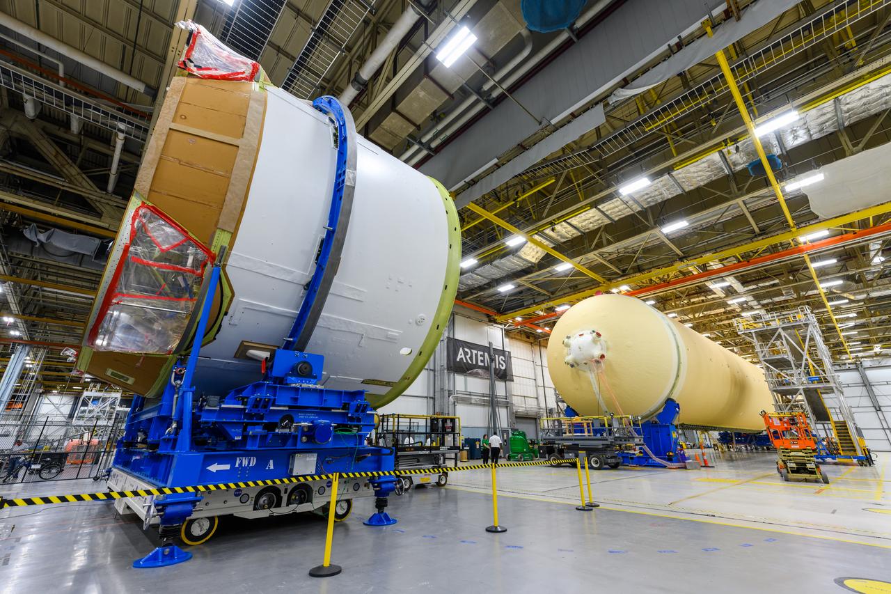
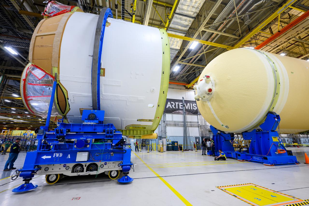
Technicians at NASA’s Michoud Assembly Facility in New Orleans moved the engine section of NASA’s Space Launch System (SLS) rocket for Artemis II, the first crewed mission to the Moon, into position for the final join of the core stage Feb. 22. The engine section is the bottom-most portion of the 212-foot-tall core stage. It is the last of five major elements that is needed to connect the stage into one major structure. In addition to its miles of cabling and hundreds of sensors, the engine section is a crucial attachment point for the four RS-25 engines and two solid rocket boosters that produce a combined 8.8 million pounds of thrust at liftoff and flight. During launch and flight, liquid propellants from the liquid hydrogen tank and liquid oxygen tanks are delivered through the engine section to the four RS-25 engines. The engine section also includes the avionics that help steer the engines after liftoff. Next, teams will join the engine section to the core stage for the second SLS rocket. After the join is complete, teams will begin to add each of the four RS-25 engines one by one to complete the stage. The completely assembled stage with its four RS-25 engines will be shipped to NASA’s Kennedy Space Center in Florida later this year. The SLS rocket is the only rocket capable of carrying astronauts in Orion around the Moon in a single mission.
Technicians at NASA’s Michoud Assembly Facility in New Orleans moved the engine section of NASA’s Space Launch System (SLS) rocket for Artemis II, the first crewed mission to the Moon, into position for the final join of the core stage Feb. 22. The engine section is the bottom-most portion of the 212-foot-tall core stage. It is the last of five major elements that is needed to connect the stage into one major structure. In addition to its miles of cabling and hundreds of sensors, the engine section is a crucial attachment point for the four RS-25 engines and two solid rocket boosters that produce a combined 8.8 million pounds of thrust at liftoff and flight. During launch and flight, liquid propellants from the liquid hydrogen tank and liquid oxygen tanks are delivered through the engine section to the four RS-25 engines. The engine section also includes the avionics that help steer the engines after liftoff. Next, teams will join the engine section to the core stage for the second SLS rocket. After the join is complete, teams will begin to add each of the four RS-25 engines one by one to complete the stage. The completely assembled stage with its four RS-25 engines will be shipped to NASA’s Kennedy Space Center in Florida later this year. The SLS rocket is the only rocket capable of carrying astronauts in Orion around the Moon in a single mission.
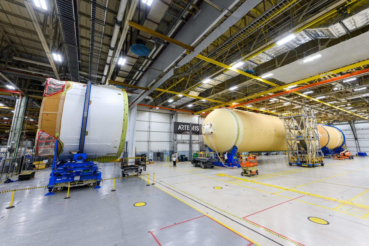
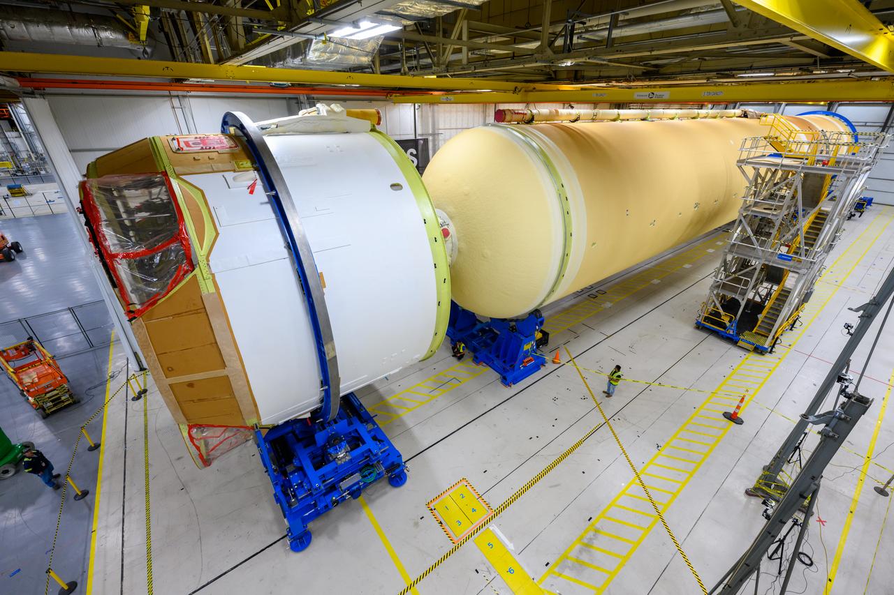
Technicians at NASA’s Michoud Assembly Facility in New Orleans moved the engine section of NASA’s Space Launch System (SLS) rocket for Artemis II, the first crewed mission to the Moon, into position for the final join of the core stage Feb. 22. The engine section is the bottom-most portion of the 212-foot-tall core stage. It is the last of five major elements that is needed to connect the stage into one major structure. In addition to its miles of cabling and hundreds of sensors, the engine section is a crucial attachment point for the four RS-25 engines and two solid rocket boosters that produce a combined 8.8 million pounds of thrust at liftoff and flight. During launch and flight, liquid propellants from the liquid hydrogen tank and liquid oxygen tanks are delivered through the engine section to the four RS-25 engines. The engine section also includes the avionics that help steer the engines after liftoff. Next, teams will join the engine section to the core stage for the second SLS rocket. After the join is complete, teams will begin to add each of the four RS-25 engines one by one to complete the stage. The completely assembled stage with its four RS-25 engines will be shipped to NASA’s Kennedy Space Center in Florida later this year. The SLS rocket is the only rocket capable of carrying astronauts in Orion around the Moon in a single mission.
Technicians at NASA’s Michoud Assembly Facility in New Orleans moved the engine section of NASA’s Space Launch System (SLS) rocket for Artemis II, the first crewed mission to the Moon, into position for the final join of the core stage Feb. 22. The engine section is the bottom-most portion of the 212-foot-tall core stage. It is the last of five major elements that is needed to connect the stage into one major structure. In addition to its miles of cabling and hundreds of sensors, the engine section is a crucial attachment point for the four RS-25 engines and two solid rocket boosters that produce a combined 8.8 million pounds of thrust at liftoff and flight. During launch and flight, liquid propellants from the liquid hydrogen tank and liquid oxygen tanks are delivered through the engine section to the four RS-25 engines. The engine section also includes the avionics that help steer the engines after liftoff. Next, teams will join the engine section to the core stage for the second SLS rocket. After the join is complete, teams will begin to add each of the four RS-25 engines one by one to complete the stage. The completely assembled stage with its four RS-25 engines will be shipped to NASA’s Kennedy Space Center in Florida later this year. The SLS rocket is the only rocket capable of carrying astronauts in Orion around the Moon in a single mission.
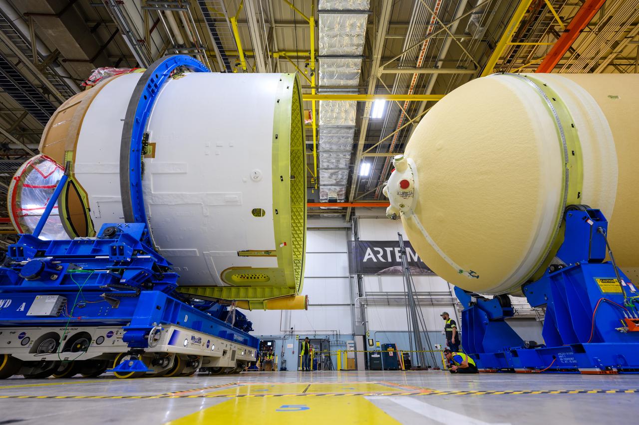
Technicians at NASA’s Michoud Assembly Facility in New Orleans moved the engine section of NASA’s Space Launch System (SLS) rocket for Artemis II, the first crewed mission to the Moon, into position for the final join of the core stage Feb. 22. The engine section is the bottom-most portion of the 212-foot-tall core stage. It is the last of five major elements that is needed to connect the stage into one major structure. In addition to its miles of cabling and hundreds of sensors, the engine section is a crucial attachment point for the four RS-25 engines and two solid rocket boosters that produce a combined 8.8 million pounds of thrust at liftoff and flight. During launch and flight, liquid propellants from the liquid hydrogen tank and liquid oxygen tanks are delivered through the engine section to the four RS-25 engines. The engine section also includes the avionics that help steer the engines after liftoff. Next, teams will join the engine section to the core stage for the second SLS rocket. After the join is complete, teams will begin to add each of the four RS-25 engines one by one to complete the stage. The completely assembled stage with its four RS-25 engines will be shipped to NASA’s Kennedy Space Center in Florida later this year. The SLS rocket is the only rocket capable of carrying astronauts in Orion around the Moon in a single mission.
Technicians at NASA’s Michoud Assembly Facility in New Orleans moved the engine section of NASA’s Space Launch System (SLS) rocket for Artemis II, the first crewed mission to the Moon, into position for the final join of the core stage Feb. 22. The engine section is the bottom-most portion of the 212-foot-tall core stage. It is the last of five major elements that is needed to connect the stage into one major structure. In addition to its miles of cabling and hundreds of sensors, the engine section is a crucial attachment point for the four RS-25 engines and two solid rocket boosters that produce a combined 8.8 million pounds of thrust at liftoff and flight. During launch and flight, liquid propellants from the liquid hydrogen tank and liquid oxygen tanks are delivered through the engine section to the four RS-25 engines. The engine section also includes the avionics that help steer the engines after liftoff. Next, teams will join the engine section to the core stage for the second SLS rocket. After the join is complete, teams will begin to add each of the four RS-25 engines one by one to complete the stage. The completely assembled stage with its four RS-25 engines will be shipped to NASA’s Kennedy Space Center in Florida later this year. The SLS rocket is the only rocket capable of carrying astronauts in Orion around the Moon in a single mission.
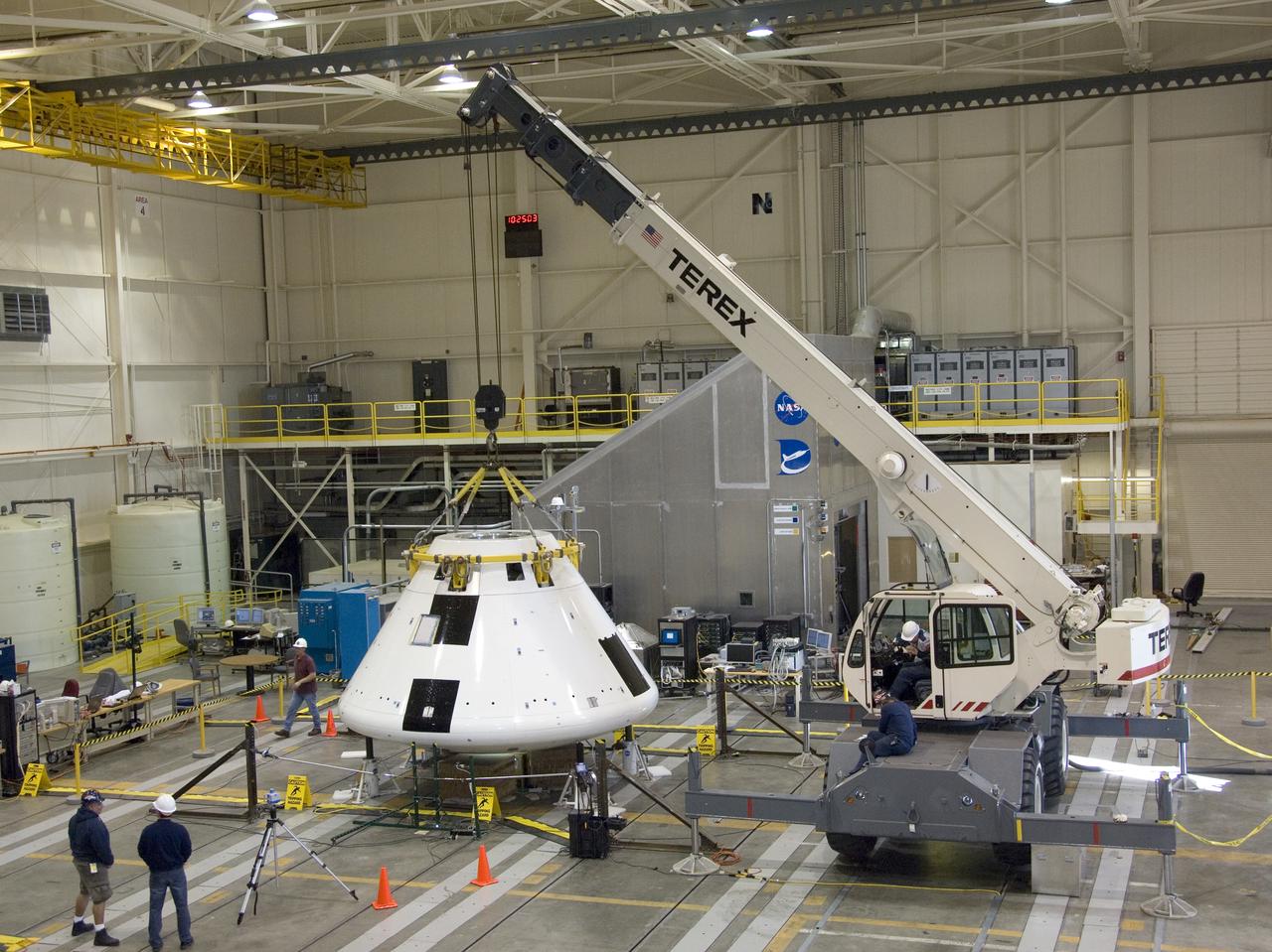
Under the watchful eyes of technicians, a crane positions the Orion PA-1 Abort Flight Test module for mass properties testing in NASA Dryden's Flight Loads Lab.
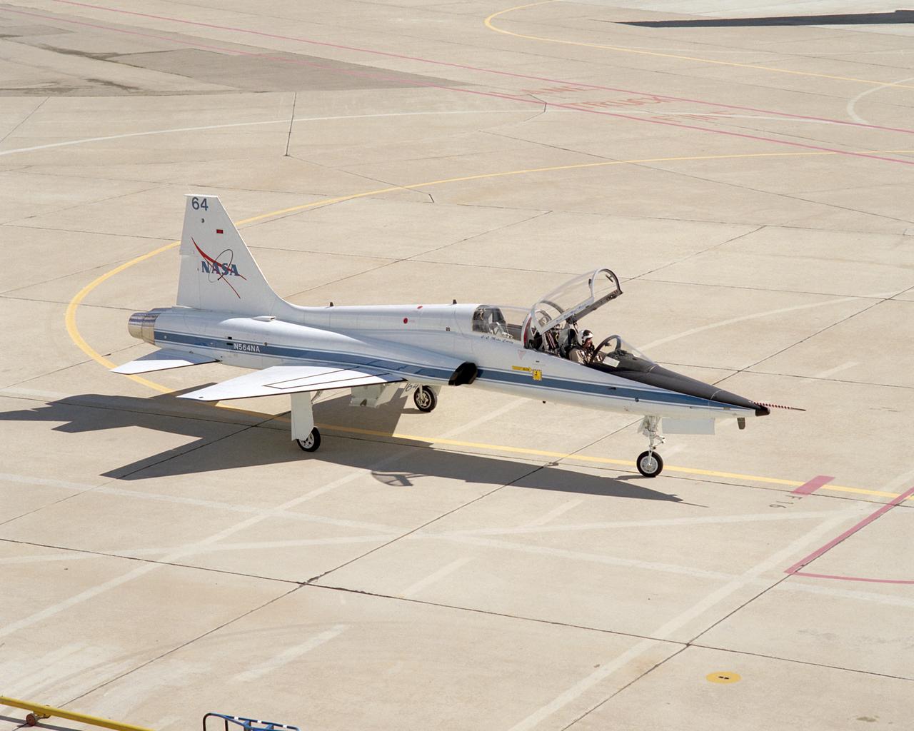
Pilot Gordon Fullerton taxies NASA Dryden's "newest" mission support aircraft, a T-38 Talon, into position on the ramp upon its arrival on February 24, 2005.
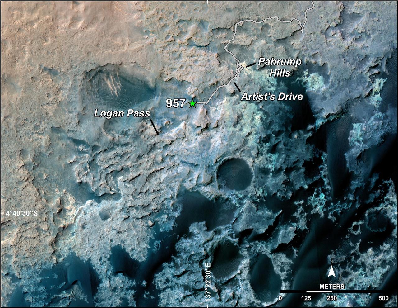
A green star marks the location of NASA's Curiosity Mars rover after a drive on the mission's 957th Martian day, or sol, (April 16, 2015). The map covers an area about 1.25 miles (2 kilometers) wide. Curiosity landed on Mars in August 2012. The drive on Sol 957 brought the mission's total driving distance past the 10-kilometer mark (6.214 miles). The rover is passing through a series of shallow valleys on a path from the "Pahrump Hills" outcrop, which it investigated for six months, toward its next science destination, called "Logan Pass." The rover's traverse line enters this map at the location Curiosity reached in mid-July 2014. The base map uses imagery from the High Resolution Imaging Science Experiment (HiRISE) camera on NASA's Mars Reconnaissance Orbiter. http://photojournal.jpl.nasa.gov/catalog/PIA19390
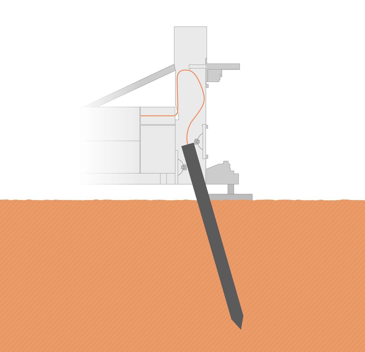
The self-hammering "mole," part of the Heat Flow and Physical Properties Package (HP3) on NASA's InSight lander, was only partially buried in the soil of Mars as of early June 2019, as shown in this illustration. Engineering analysis has determined that the bottom of the mole is currently about 12-14 inches (30-35 centimeters) deep into Martian ground, with a bit of its top still inside the HP3 support structure. The mole is tilted about 19 degrees. https://photojournal.jpl.nasa.gov/catalog/PIA23274
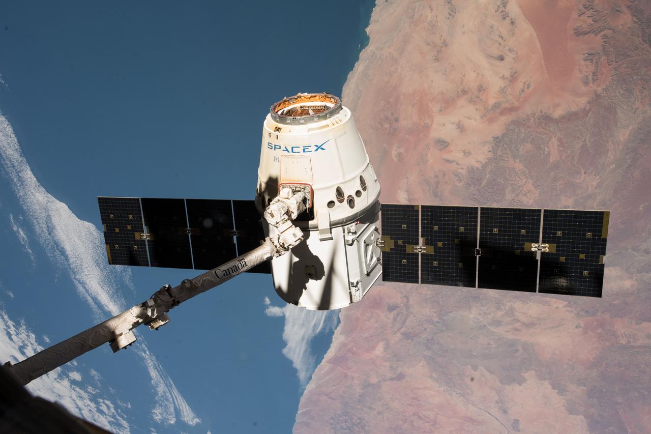
iss055e057155 (May 5, 2018) --- The SpaceX Dragon cargo craft is pictured in the grips of the Canadarm2 robotic arm as the International Space Station was orbiting across the central coast of Namibia. Dragon was later released for its splashdown in the Pacific Ocean off the coast of California on May 5, 2018 ending the SpaceX CRS-14 mission.
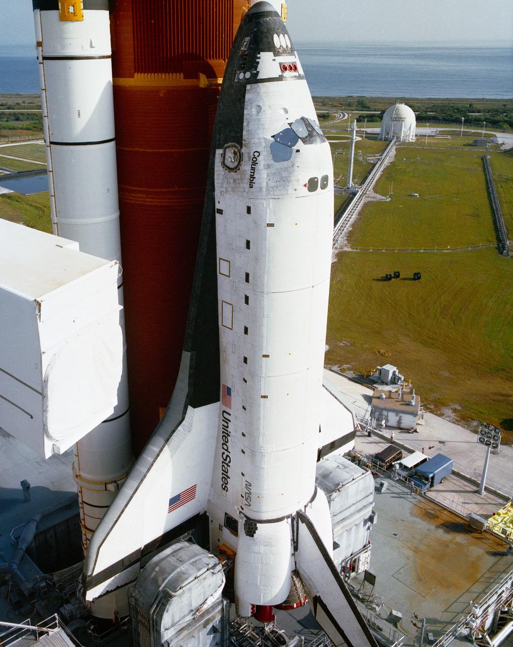
S89-51983 (18 Nov 1989) --- Roll-out of the Space Shuttle Columbia is completed as the vehicle, atop the Mobile Launcher Platform, is positioned on the hard stand at Pad 39A. The approximately eight-hour journey from the Vehicle Assembly Building began at 2:32 a.m. EST. This marks the first time a Space Shuttle has been at Pad A at Launch Complex 39 since January 12, 1986, when Columbia was launched on mission 61C. Pad A will next be used for the launch of Columbia and a five person crew on the STS-32 mission, presently scheduled for no earlier than December 18, 1989.
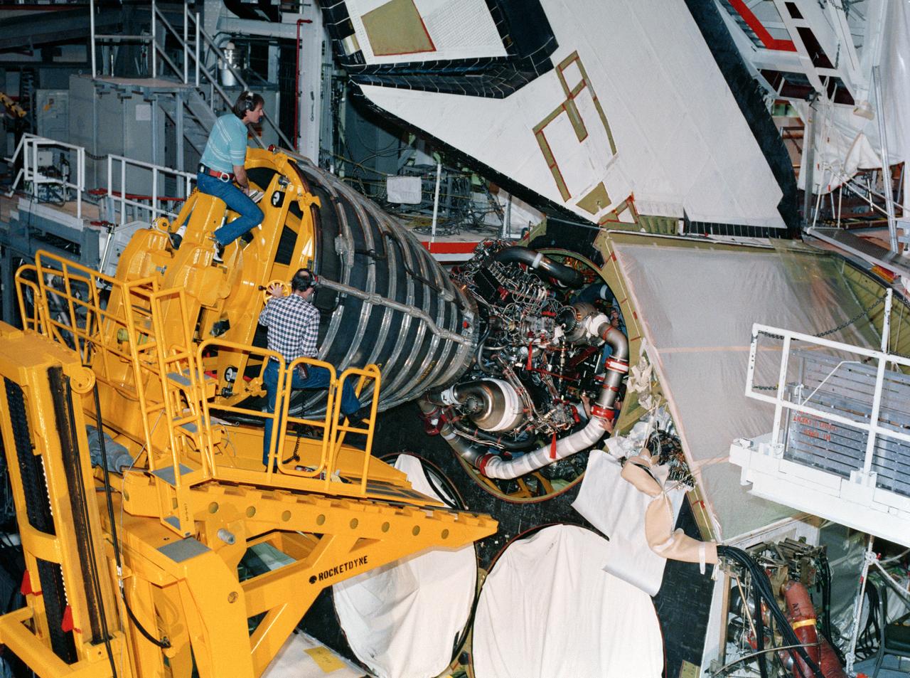
S88-29076 (10 Jan 1988) --- KSC employees work together to carefully guide a 7,000 pound main engine into the number one position in Discovery's aft compartment. Because of the engine's weight and size, special handling equipment is needed to perform the installation. Discovery is currently being prepared for the upcoming STS-26 mission in bay 1 of the Orbiter Processing Facility. This engine, 2019, arrived at KSC on Jan. 6 and was installed Jan. 10. The other two engines are scheduled to be installed later this month. The shuttle's three main liquid fueled engines provide the main propulsion for the orbiter vehicle. The cluster of three engines operate in parallel with the solid rocket boosters during the initial ascent.
A Martian mechanic checks beneath the completely deployed NASA Rover 1 lander. Atop the lander is Rover 1 with its wheels and solar arrays in the stowed position.

This graphic depicts the position of the Philae lander of the European Space Agency Rosetta mission in the context of topographic modeling of the surface of comet 67P/Churyumov-Gerasimenko nucleus.
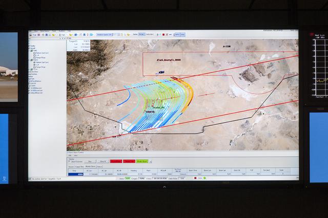
The CISBoomDA display allows the pilot of a supersonic aircraft to monitor the locations of any sonic booms produced, to prevent the aircraft from positioning booms in restricted area.
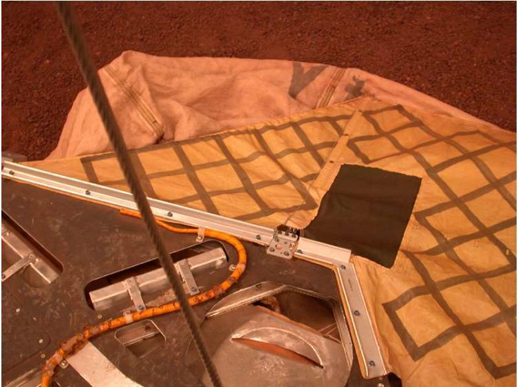
This image shows the airbags in deflated position at the JPL In-Situ Instrument Laboratory, where engineers tested the airbags to ensure a safe landing on Mars.
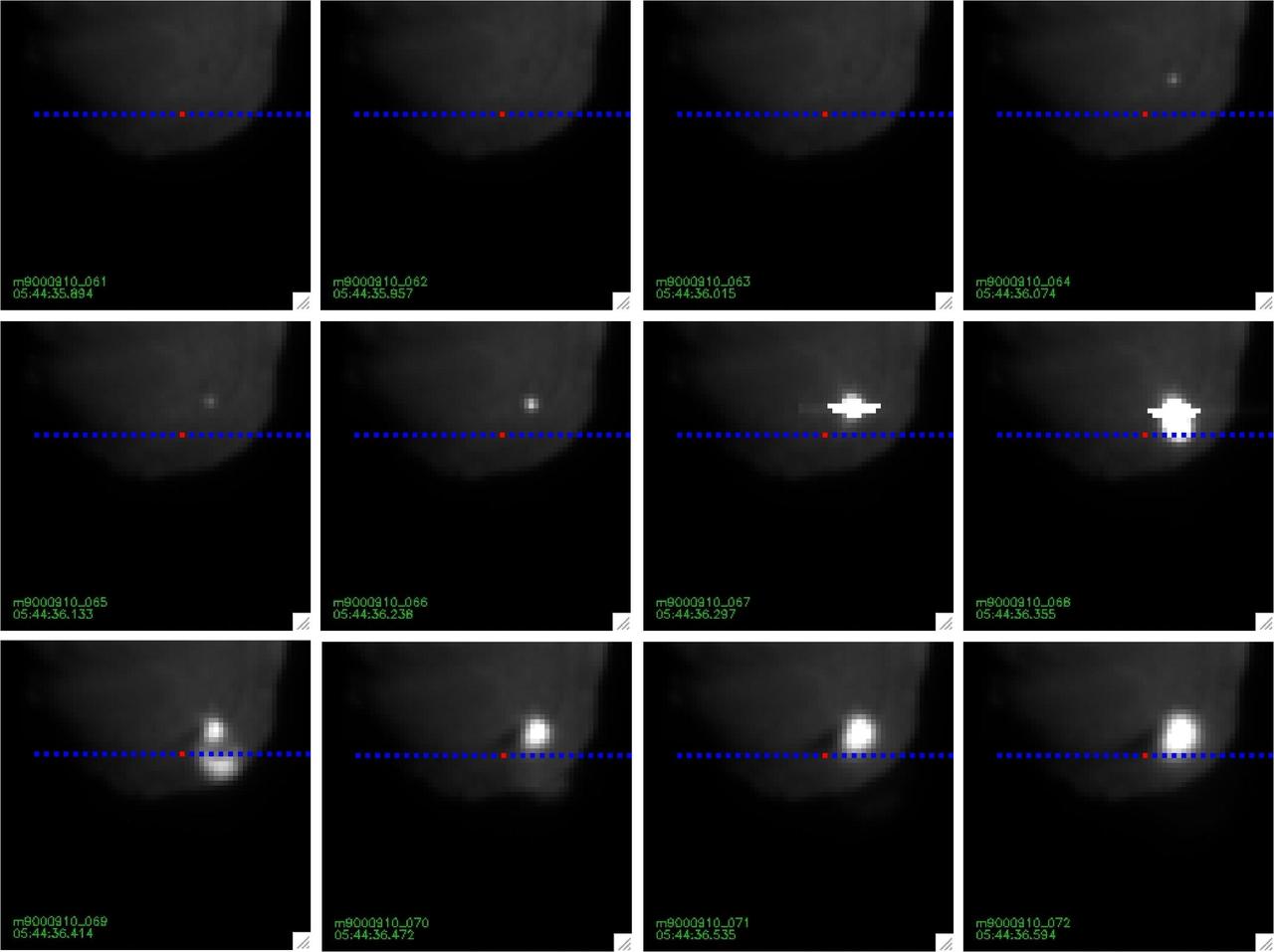
NASA Deep Impact Tempel 1 Mission Update. Images of impact taken with the medium resolution imager. The blue dotted line is the position of the spectrometer slit.
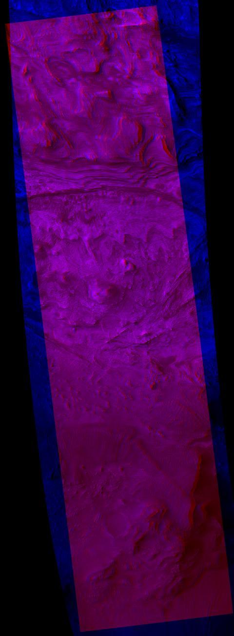
A stereo view shows fractures called joints. They have a ridge-like shape, standing out in positive relief as the surrounding bedrock is eroded away faster than they are