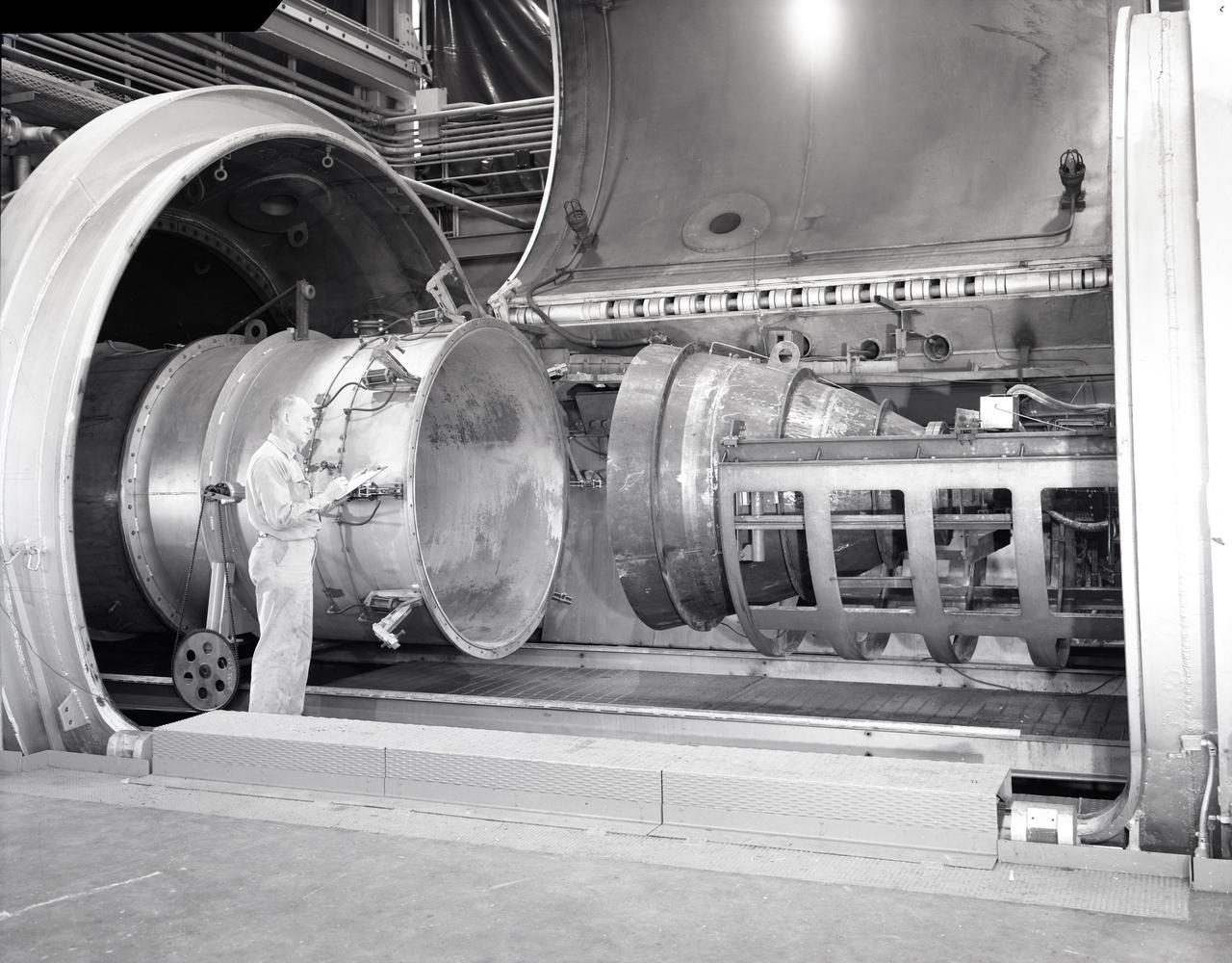
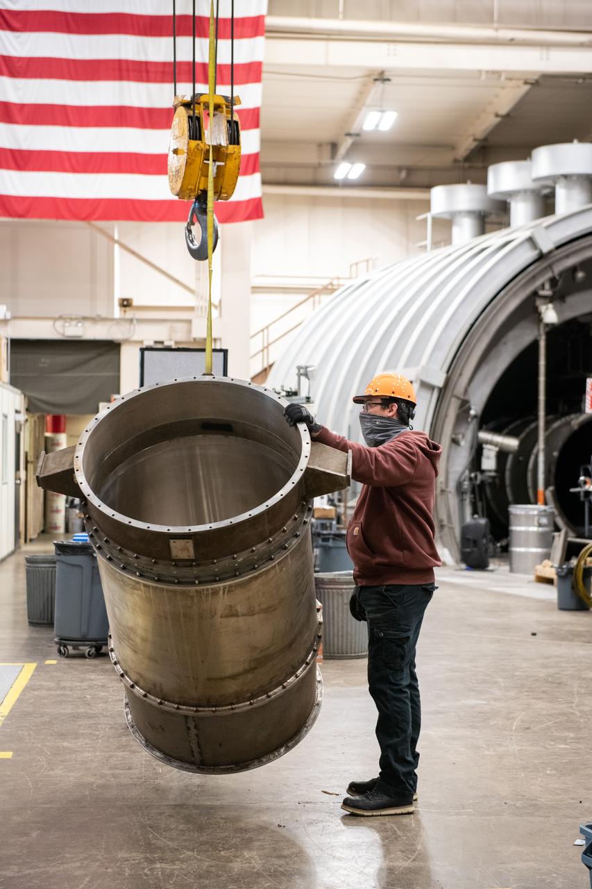
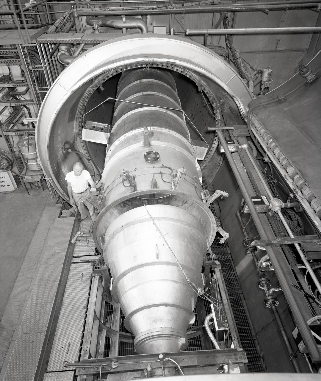
APOLLO CONTOUR ENGINE MOUNTED IN THE PROPULSION SYSTEMS LABORATORY PSL NO. 2 TEST CELL
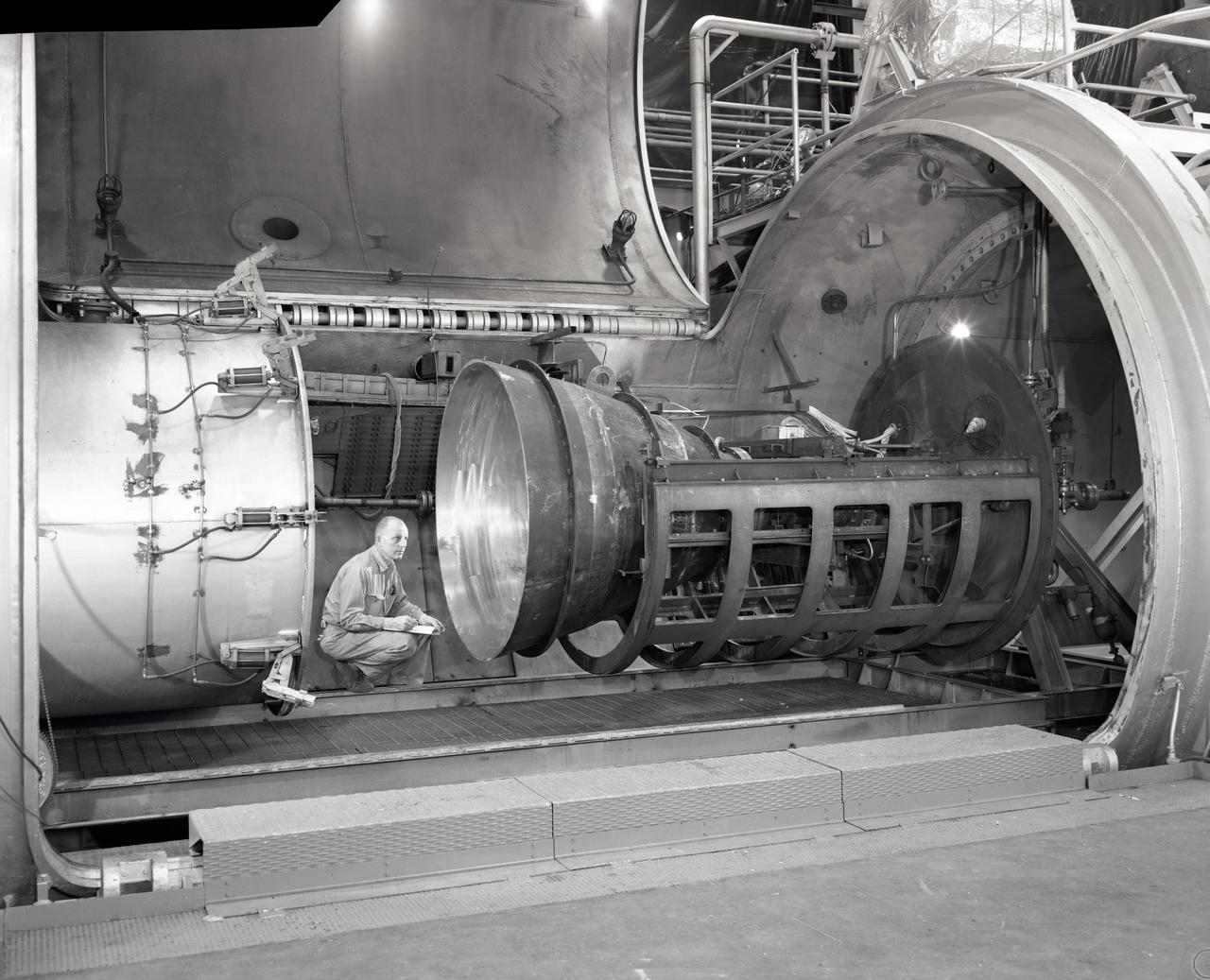
APOLLO CONTOUR ENGINE MOUNTED IN THE PROPULSION SYSTEMS LABORATORY PSL NO. 2 TEST CELL
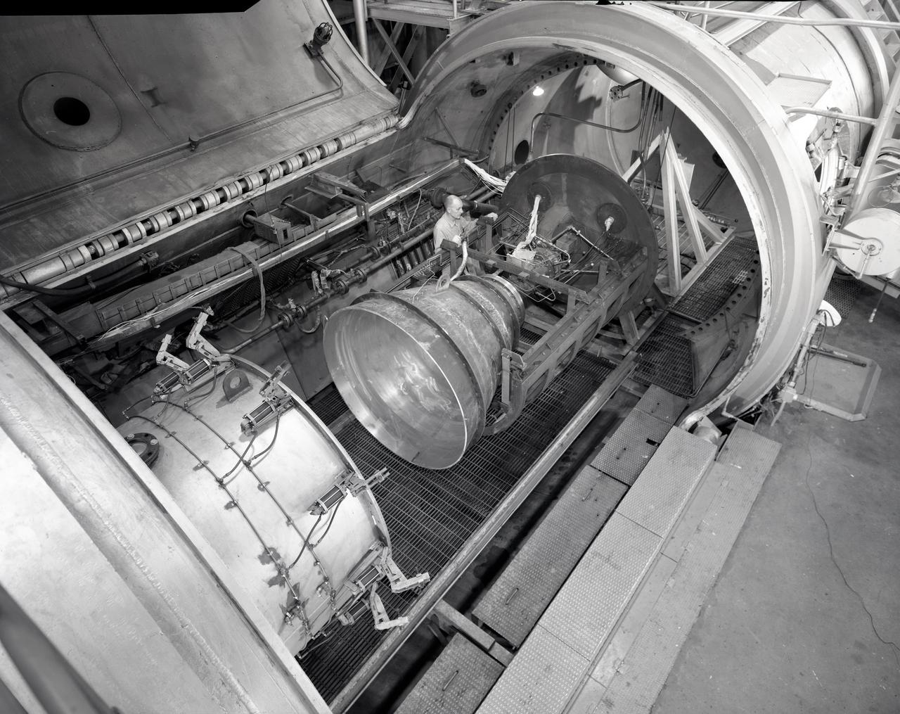
APOLLO CONTOUR ENGINE MOUNTED IN THE PROPULSION SYSTEMS LABORATORY PSL NO. 2 TEST CELL
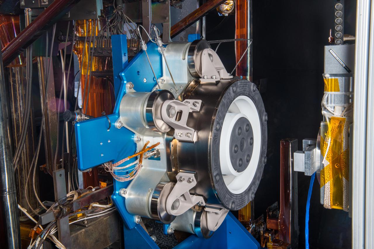
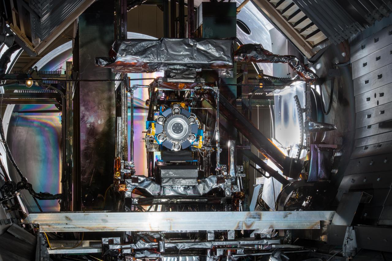
Advanced Electric Propulsion System, AEPS, Engineering Test Unit 2, ETU-2, Thruster Hardware
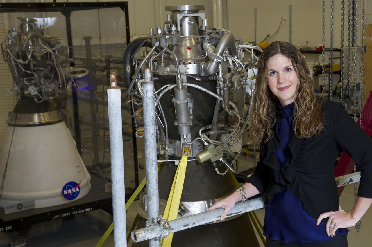
PROPULSION SYSTEMS ENGINEER ERIN BETTS IN MSFC PROPULSION ENGINEERING LAB
Advanced Electric Propulsion System, AEPS, Engineering Test Unit 2, ETU-2, Thruster Hardware
Advanced Electric Propulsion System, AEPS, Engineering Test Unit 2, ETU-2, Thruster Hardware
Advanced Electric Propulsion System, AEPS, Engineering Test Unit 2, ETU-2, Thruster Hardware
Advanced Electric Propulsion System, AEPS, Engineering Test Unit 2, ETU-2, Thruster Hardware
Advanced Electric Propulsion System, AEPS, Engineering Test Unit 2, ETU-2, Thruster Hardware

Advanced Electric Propulsion System, AEPS, Engineering Test Unit 2, ETU-2, Thruster Hardware
Advanced Electric Propulsion System, AEPS, Engineering Test Unit 2, ETU-2, Thruster Hardware
Advanced Electric Propulsion System, AEPS, Engineering Test Unit 2, ETU-2, Thruster Hardware
Advanced Electric Propulsion System, AEPS, Engineering Test Unit 2, ETU-2, Thruster Hardware
Advanced Electric Propulsion System, AEPS, Engineering Test Unit 2, ETU-2, Thruster Hardware
Advanced Electric Propulsion System, AEPS, Engineering Test Unit 2, ETU-2, Thruster Hardware

Advanced Electric Propulsion System, AEPS, Engineering Test Unit 2, ETU-2, Thruster Hardware

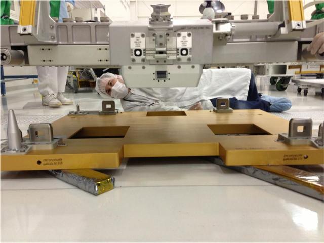
Researchers at the Marshall Space Flight Center (MSFC) have designed, fabricated, and tested the first solar thermal engine, a non-chemical rocket engine that produces lower thrust but has better thrust efficiency than a chemical combustion engine. This photograph shows components for the thermal propulsion engine being laid out prior to assembly. MSFC turned to solar thermal propulsion in the early 1990s due to its simplicity, safety, low cost, and commonality with other propulsion systems. As part of MSFC's Space Transportation Directorate, the Propulsion Research Center serves as a national resource for research of advanced, revolutionary propulsion technologies. The mission is to move the Nation's capabilities beyond the confines of conventional chemical propulsion into an era of aircraft-like access to Earth-orbit, rapid travel throughout the solar system, and exploration of interstellar space.

A simple sketch on a TWA napkin by NASA Dryden engineer Frank W. "Bill" Burcham led to development and validation of the Propulsion-Controlled Aircraft concept.
American Society of Mechanical Engineers, ASME Nozzle Test at Propulsion Systems Laboratory, PSL Documentation Photographs
American Society of Mechanical Engineers, ASME Nozzle Test at Propulsion Systems Laboratory, PSL
American Society of Mechanical Engineers, ASME Nozzle Test at Propulsion Systems Laboratory, PSL
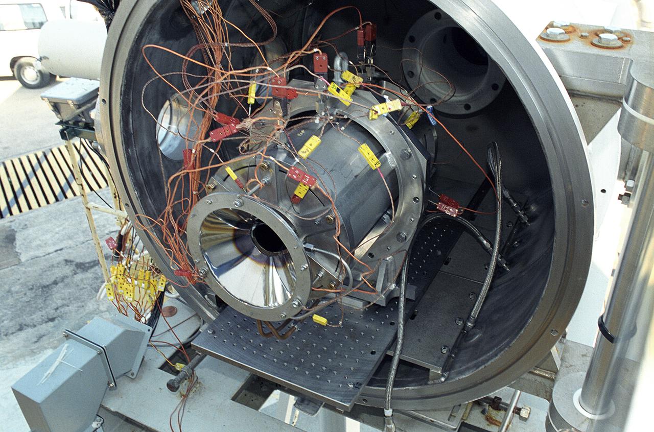
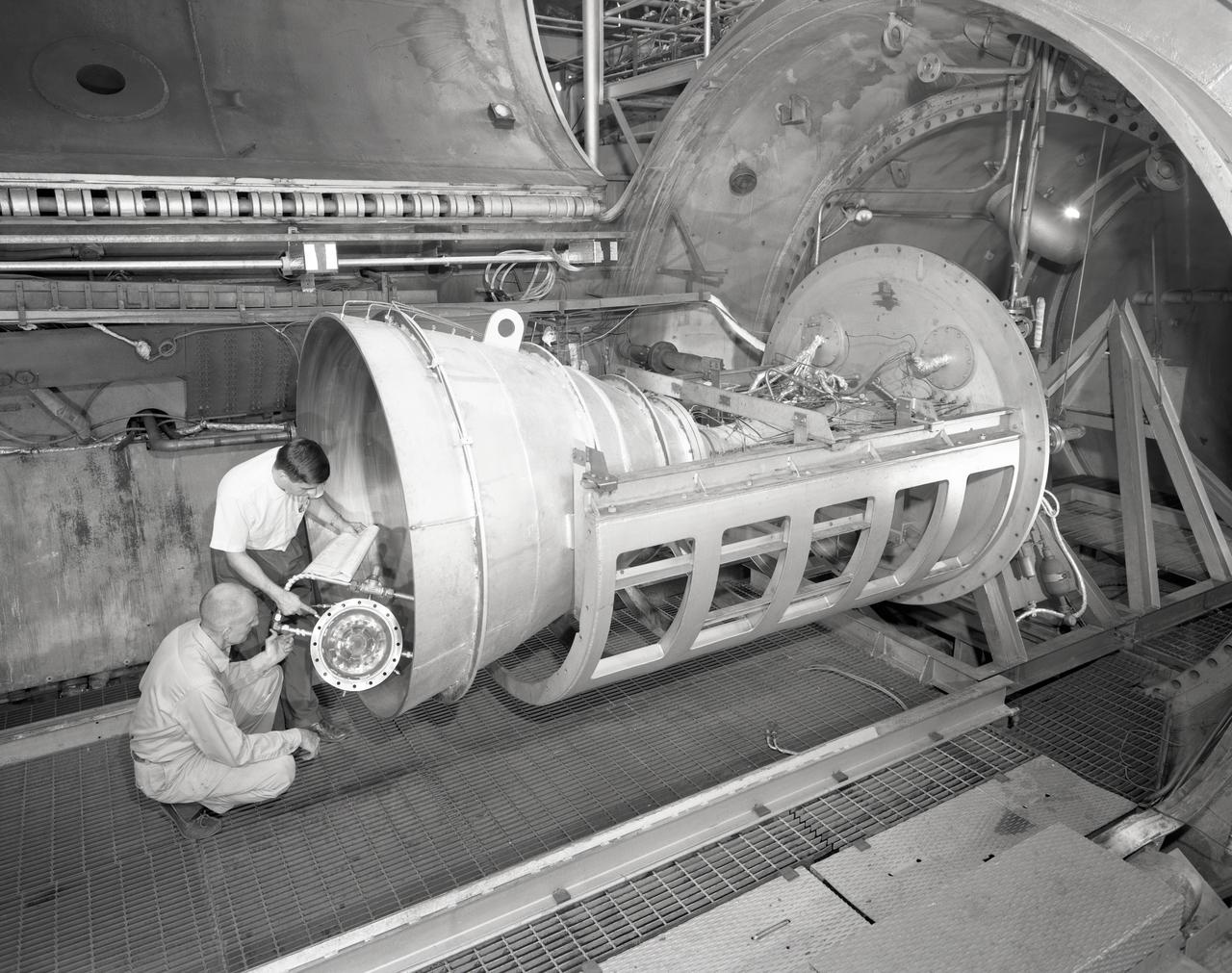
Researchers at the Marshall Space Flight Center (MSFC) have designed, fabricated, and tested the first solar thermal engine, a non-chemical rocket engine that produces lower thrust but has better thrust efficiency than a chemical combustion engine. MSFC turned to solar thermal propulsion in the early 1990s due to its simplicity, safety, low cost, and commonality with other propulsion systems. Solar thermal propulsion works by acquiring and redirecting solar energy to heat a propellant. This photograph shows a fully assembled solar thermal engine placed inside the vacuum chamber at the test facility prior to testing. The 20- by 24-ft heliostat mirror (not shown in this photograph) has a dual-axis control that keeps a reflection of the sunlight on the 18-ft diameter concentrator mirror, which then focuses the sunlight to a 4-in focal point inside the vacuum chamber. The focal point has 10 kilowatts of intense solar power. As part of MSFC's Space Transportation Directorate, the Propulsion Research Center serves as a national resource for research of advanced, revolutionary propulsion technologies. The mission is to move theNation's capabilities beyond the confines of conventional chemical propulsion into an era of aircraft-like access to Earth orbit, rapid travel throughout the solar system, and exploration of interstellar space.
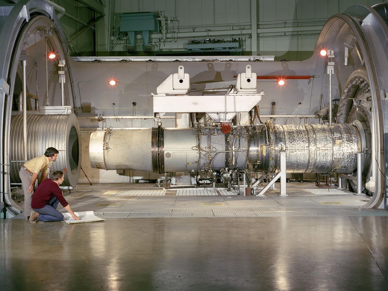
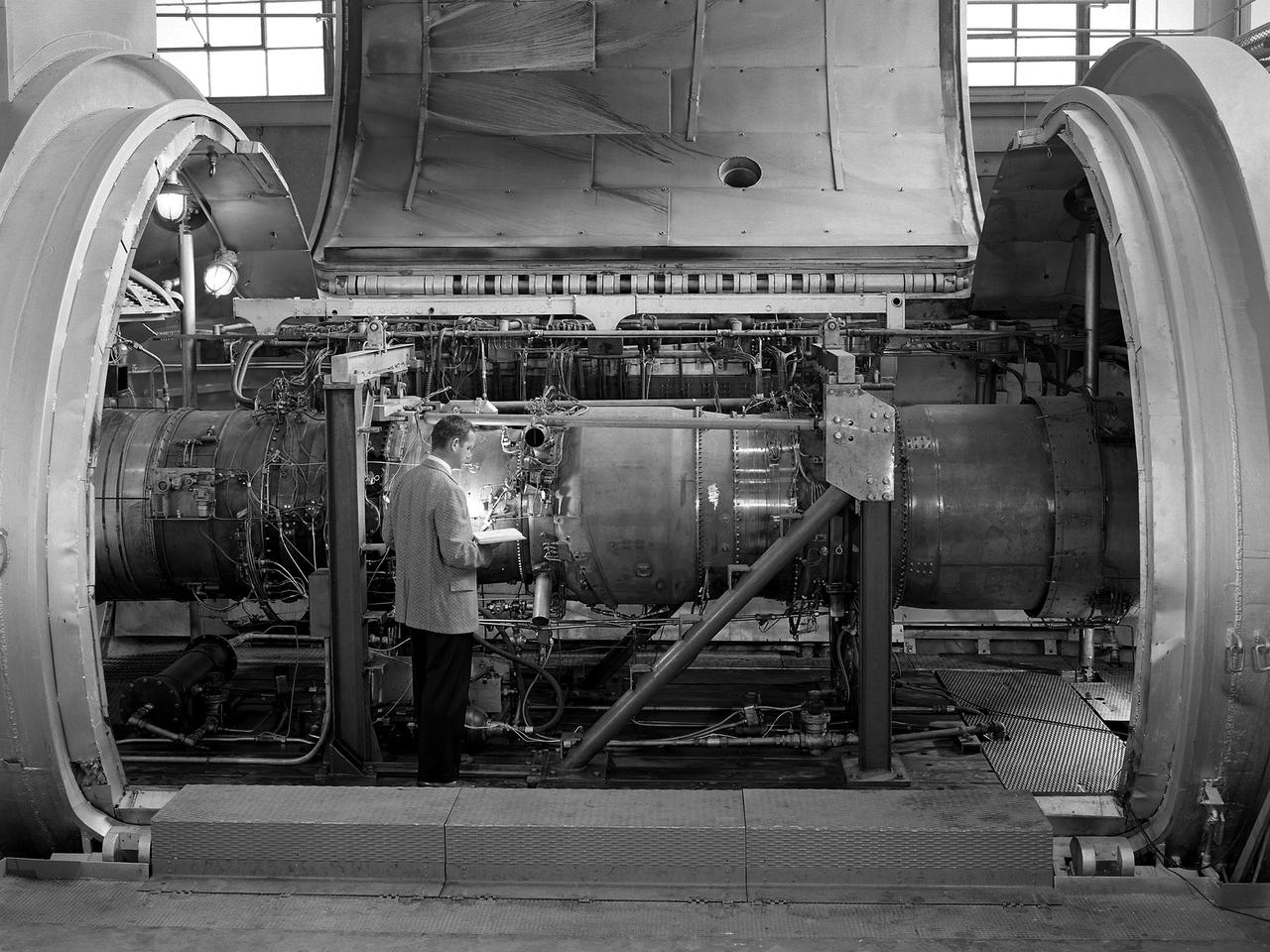
A refanned Pratt and Whitney JT-8D-109 turbofan engine installed in Cell 4 of the Propulsion Systems Laboratory at the National Aeronautics and Space Administration (NASA) Lewis Research Center. NASA Lewis’ Refan Program sought to demonstrate that noise reduction modifications could be applied to existing aircraft engines with minimal costs and without diminishing the engine’s performance or integrity. At the time, Pratt and Whitney’s JT-8D turbofans were one of the most widely used engines in the commercial airline industry. The engines powered Boeing’s 727 and 737 and McDonnell Douglas’ DC-9 aircraft. Pratt and Whitney worked with the airline manufacturers on a preliminary study that verified feasibility of replacing the JT-8D’s two-stage fan with a larger single-stage fan. The new fan slowed the engine’s exhaust, which significantly reduced the amount of noise it generated. Booster stages were added to maintain the proper level of airflow through the engine. Pratt and Whitney produced six of the modified engines, designated JT-8D-109, and performed the initial testing. One of the JT-8D-109 engines, seen here, was tested in simulated altitude conditions in NASA Lewis’ Propulsion Systems Laboratory. The Refan engine was ground-tested on an actual aircraft before making a series of flight tests on 727 and DC-9 aircraft in early 1976. The Refan Program reduced the JT-8D’s noise by 50 percent while increasing the fuel efficiency. The retro-fit kits were estimated to cost between $1 million and $1.7 million per aircraft.

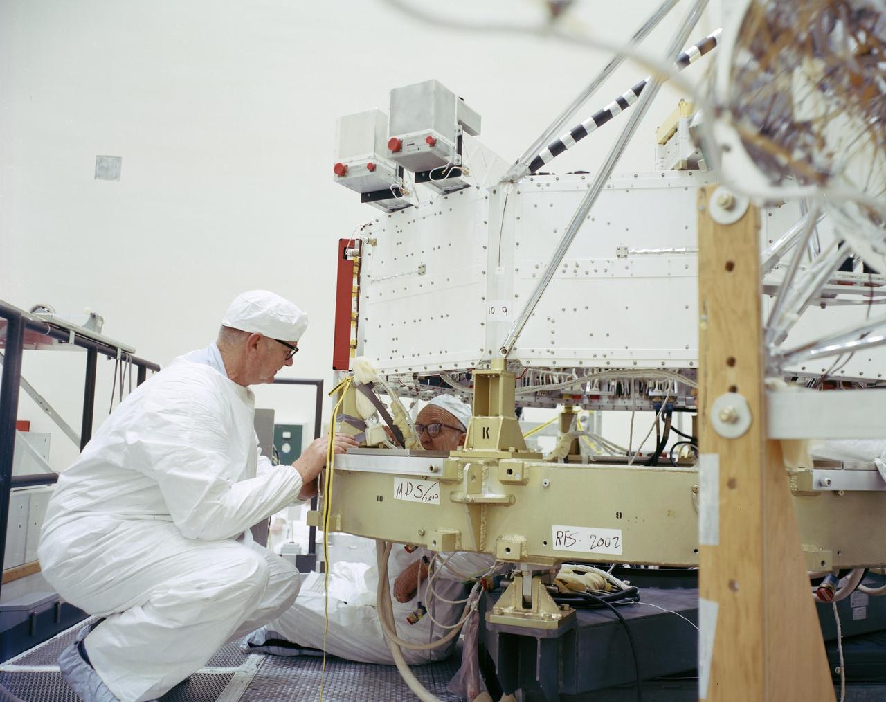
New staff member Paul Margosian inspects a cluster of ion engines in the Electric Propulsion Laboratory’s 25-foot diameter vacuum tank at the National Aeronautics and Space Administration (NASA) Lewis Research Center. Lewis researchers had been studying different methods of electric rocket propulsion since the mid-1950s. Harold Kaufman created the first successful engine, the electron bombardment ion engine, in the early 1960s. These engines used electric power to create and accelerate small particles of propellant material to high exhaust velocities. Electric engines have a very small thrust, and but can operate for long periods of time. The ion engines are often clustered together to provide higher levels of thrust. The Electric Propulsion Laboratory contained two large vacuum tanks capable of simulating the space environment. The tanks were designed especially for testing ion and plasma thrusters and spacecraft. The larger 25-foot diameter tank was intended for testing electric thrusters with condensable propellants. The tank’s test compartment, seen here, was 10 feet in diameter. Margosian joined Lewis in late 1962 during a major NASA hiring phase. The Agency reorganized in 1961 and began expanding its ranks through a massive recruiting effort. Lewis personnel increased from approximately 2,700 in 1961 to over 4,800 in 1966. Margosian, who worked with Bill Kerslake in the Electromagnetic Propulsion Division’s Propulsion Systems Section, wrote eight technical reports on mercury and electron bombardment thrusters, thermoelectrostatic generators, and a high voltage insulator.
A researcher examines the Orenda Iroquois PS.13 turbojet in a Propulsion Systems Laboratory test chamber at the National Advisory Committee for Aeronautics (NACA) Lewis Flight Propulsion Laboratory. The Iroquois was being developed to power the CF-105 Arrow fighter designed by the Avro Canada Company. Avro began design work on the Arrow jet fighter in 1952. The company’s Orenda branch suggested building a titanium-based PS.13 Iroquois engine after development problems arose with the British engines that Avro had originally intended to use. The 10-stage, 20,000-pound-thrust Iroquois would prove to be more powerful than any contemporary US or British turbojet. It was also significantly lighter and more fuel efficient. An Iroquois was sent to Cleveland in April 1957 so that Lewis researchers could study the engine’s basic performance for the air force in the Propulsion Systems Laboratory. The tests were run over a wide range of speeds and altitudes with variations in exhaust-nozzle area. Initial studies determined the Iroquois’s windmilling and ignition characteristics at high altitude. After operating for 64 minutes, the engine was reignited at altitudes up to the 63,000-foot limit of the facility. Various modifications were attempted to reduce the occurrence of stall but did not totally eradicate the problem. The Arrow jet fighter made its initial flight in March 1958 powered by a substitute engine. In February 1959, however, both the engine and the aircraft programs were cancelled. The world’s superpowers had quickly transitioned from bombers to ballistic missiles which rendered the Avro Arrow prematurely obsolete.
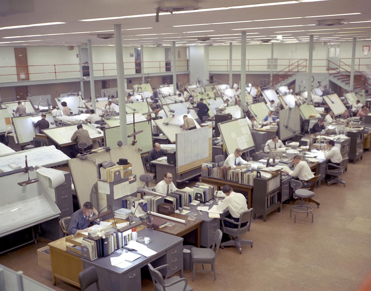
Temporary quarters in the Huntsville Industrial Center (HIC) building located in downtown Huntsville, Alabama, as Marshall Space Flight Center (MSFC) grew. This image shows drafting specialists from the Propulsion and Vehicle Engineering Laboratory at work in the HIC building.
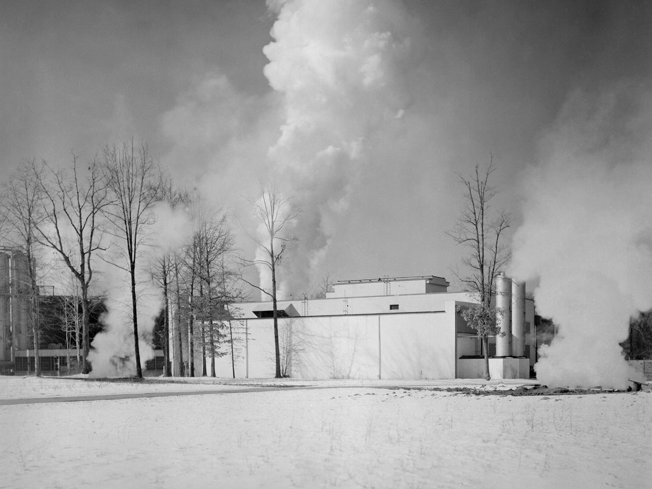
The Engine Propeller Research Building, referred to as the Prop House, emits steam from its acoustic silencers at the National Advisory Committee for Aeronautics (NACA) Lewis Flight Propulsion Laboratory. In 1942 the Prop House became the first completed test facility at the new NACA laboratory in Cleveland, Ohio. It contained four test cells designed to study large reciprocating engines. After World War II, the facility was modified to study turbojet engines. Two of the test cells were divided into smaller test chambers, resulting in a total of six engine stands. During this period the NACA Lewis Materials and Thermodynamics Division used four of the test cells to investigate jet engines constructed with alloys and other high temperature materials. The researchers operated the engines at higher temperatures to study stress, fatigue, rupture, and thermal shock. The Compressor and Turbine Division utilized another test cell to study a NACA-designed compressor installed on a full-scale engine. This design sought to increase engine thrust by increasing its airflow capacity. The higher stage pressure ratio resulted in a reduction of the number of required compressor stages. The last test cell was used at the time by the Engine Research Division to study the effect of high inlet densities on a jet engine. Within a couple years of this photograph the Prop House was significantly altered again. By 1960 the facility was renamed the Electric Propulsion Research Building to better describe its new role in electric propulsion.
Apollo Contour Engine Model being tested in the NASA Lewis Research Center, Propulsion Systems Laboratory, PSL
Apollo Contour Engine Model being tested in the NASA Lewis Research Center, Propulsion Systems Laboratory, PSL
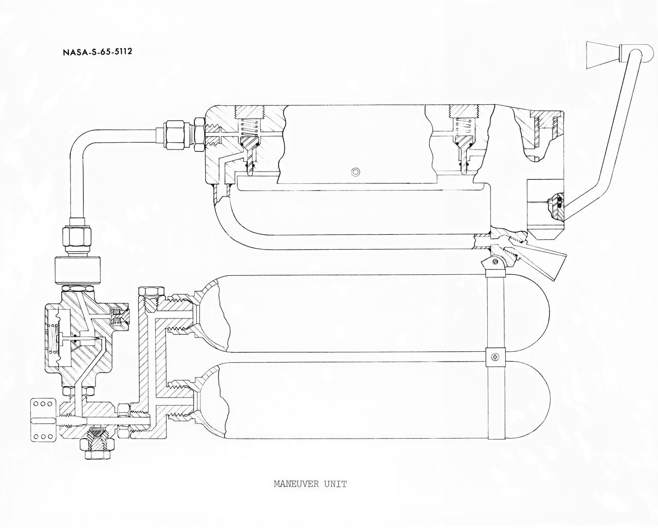
S65-05112 (30 May 1965) --- Cutaway engineering drawing showing some of the features of the zero-gravity integral propulsion unit.

A mechanic works on a General Electric I-40 turbojet at the National Advisory Committee for Aeronautics (NACA) Lewis Flight Propulsion Laboratory. The military selected General Electric’s West Lynn facility in 1941 to secretly replicate the centrifugal turbojet engine designed by British engineer Frank Whittle. General Electric’s first attempt, the I-A, was fraught with problems. The design was improved somewhat with the subsequent I-16 engine. It was not until the engine's next reincarnation as the I-40 in 1943 that General Electric’s efforts paid off. The 4000-pound thrust I-40 was incorporated into the Lockheed Shooting Star airframe and successfully flown in June 1944. The Shooting Star became the US’s first successful jet aircraft and the first US aircraft to reach 500 miles per hour. The NACA’s Lewis Flight Propulsion Laboratory studied all of General Electric’s centrifugal turbojets both during World War II and afterwards. The entire Shooting Star aircraft was investigated in the Altitude Wind Tunnel during 1945. The researchers studied the engine compressor performance, thrust augmentation using a water injection, and compared different fuel blends in a single combustor. The mechanic in this photograph is inserting a combustion liner into one of the 14 combustor cans. The compressor, which is not yet installed in this photograph, pushed high pressure air into these combustors. There the air mixed with the fuel and was heated. The hot air was then forced through a rotating turbine that powered the engine before being expelled out the nozzle to produce thrust.
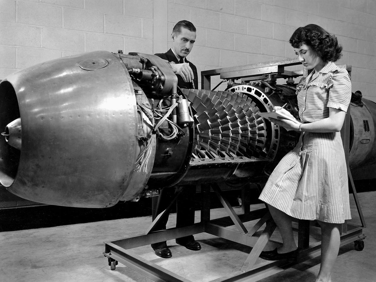
Researcher Robert Miller led an investigation into the combustor performance of a German Jumo 004 engine at the National Advisory Committee for Aeronautics (NACA) Lewis Flight Propulsion Laboratory. The Jumo 004 powered the world's first operational jet fighter, the Messerschmitt Me 262, beginning in 1942. The Me 262 was the only jet aircraft used in combat during World War II. The eight-stage axial-flow compressor Jumo 004 produced 2000 pounds of thrust. The US Army Air Forces provided the NACA with a Jumo 004 engine in 1945 to study the compressor’s design and performance. Conveniently the engine’s designer Anselm Franz had recently arrived at Wright-Patterson Air Force Base in nearby Dayton, Ohio as part of Project Paperclip. The Lewis researchers used a test rig in the Engine Research Building to analyze one of the six combustion chambers. It was difficult to isolate a single combustor’s performance when testing an entire engine. The combustion efficiency, outlet-temperature distribution, and total pressure drop were measured. The researchers determined the Jumo 004’s maximum performance was 5000 revolutions per minute at a 27,000 foot altitude and 11,000 revolutions per minute at a 45,000 foot altitude. The setup in this photograph was created for a tour of NACA Lewis by members of the Institute of Aeronautical Science on March 22, 1945.
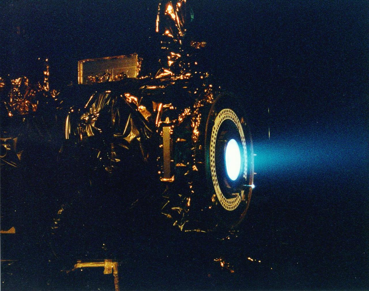
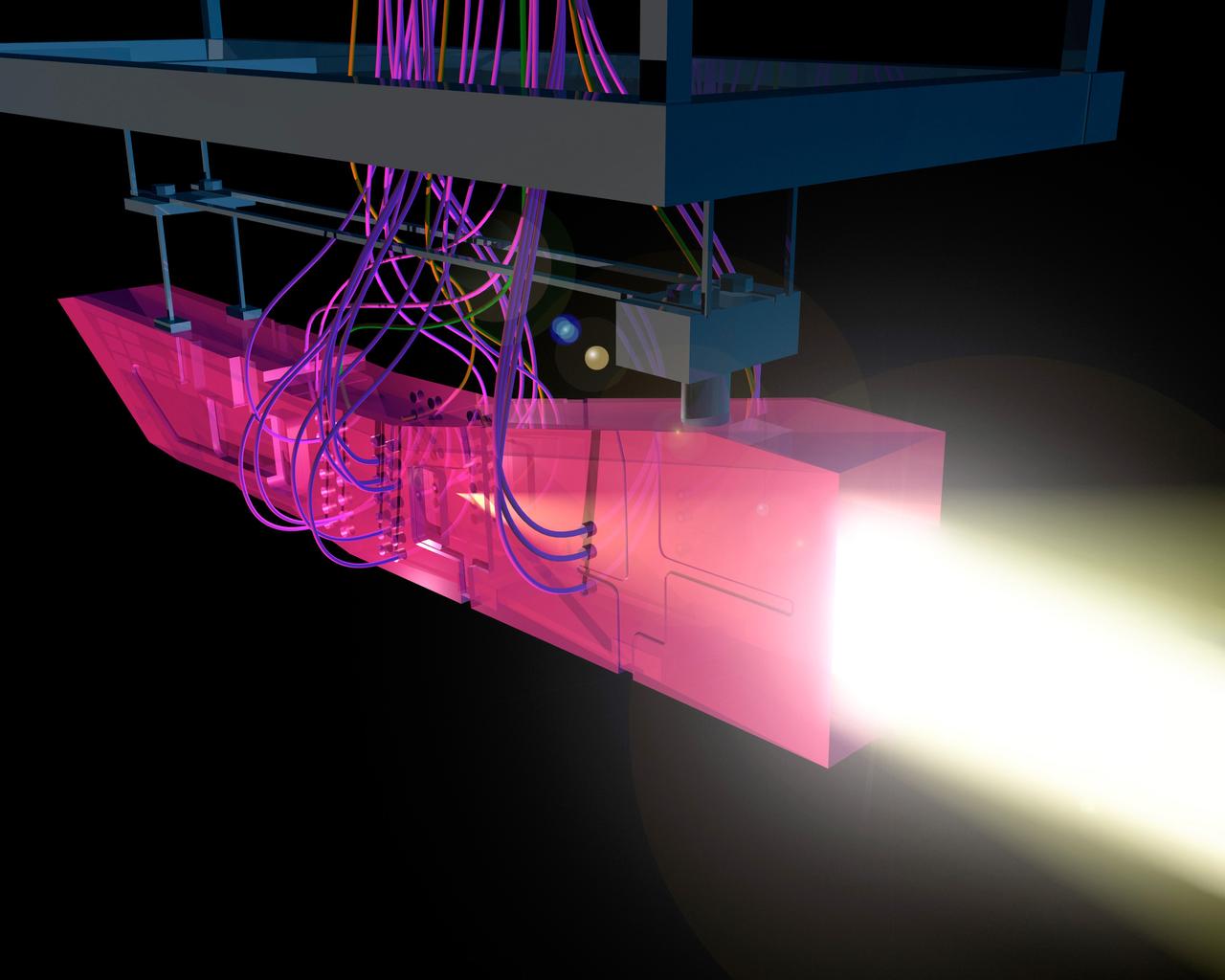
This image of a xenon ion engine, photographed through a port of the vacuum chamber where it was being tested at NASA's Jet Propulsion Laboratory, shows the faint blue glow of charged atoms being emitted from the engine. The ion propulsion engine is the first non-chemical propulsion to be used as the primary means of propelling a spacecraft. Though the thrust of the ion propulsion is about the same as the downward pressure of a single sheet of paper, by the end of the mission, the ion engine will have changed the spacecraft speed by about 13,700 kilometers/hour (8500 miles/hour). Even then, it will have expended only about 64 kg of its 81.5 kg supply of xenon propellant. http://photojournal.jpl.nasa.gov/catalog/PIA04247
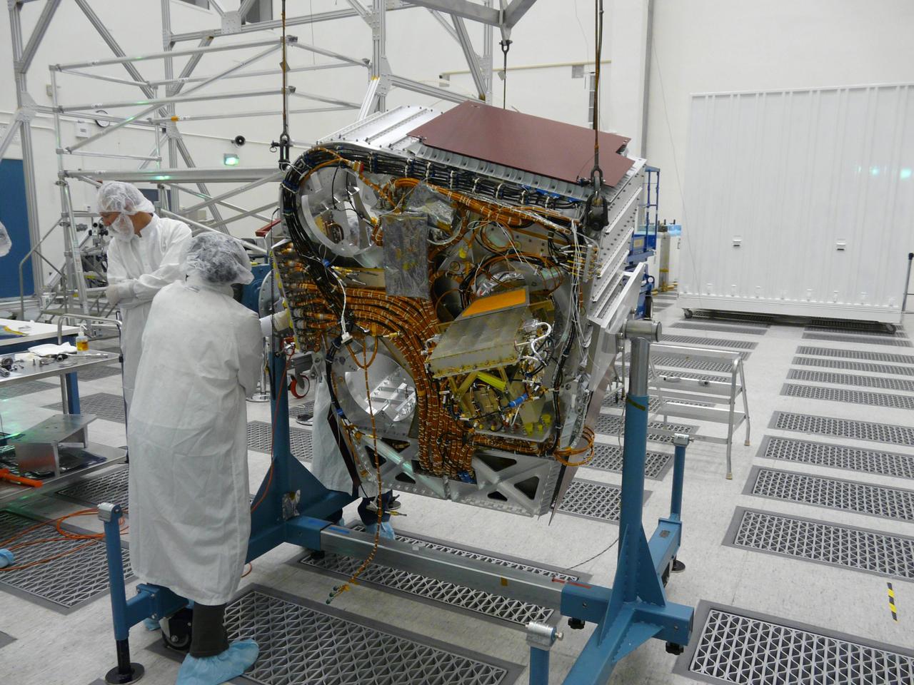
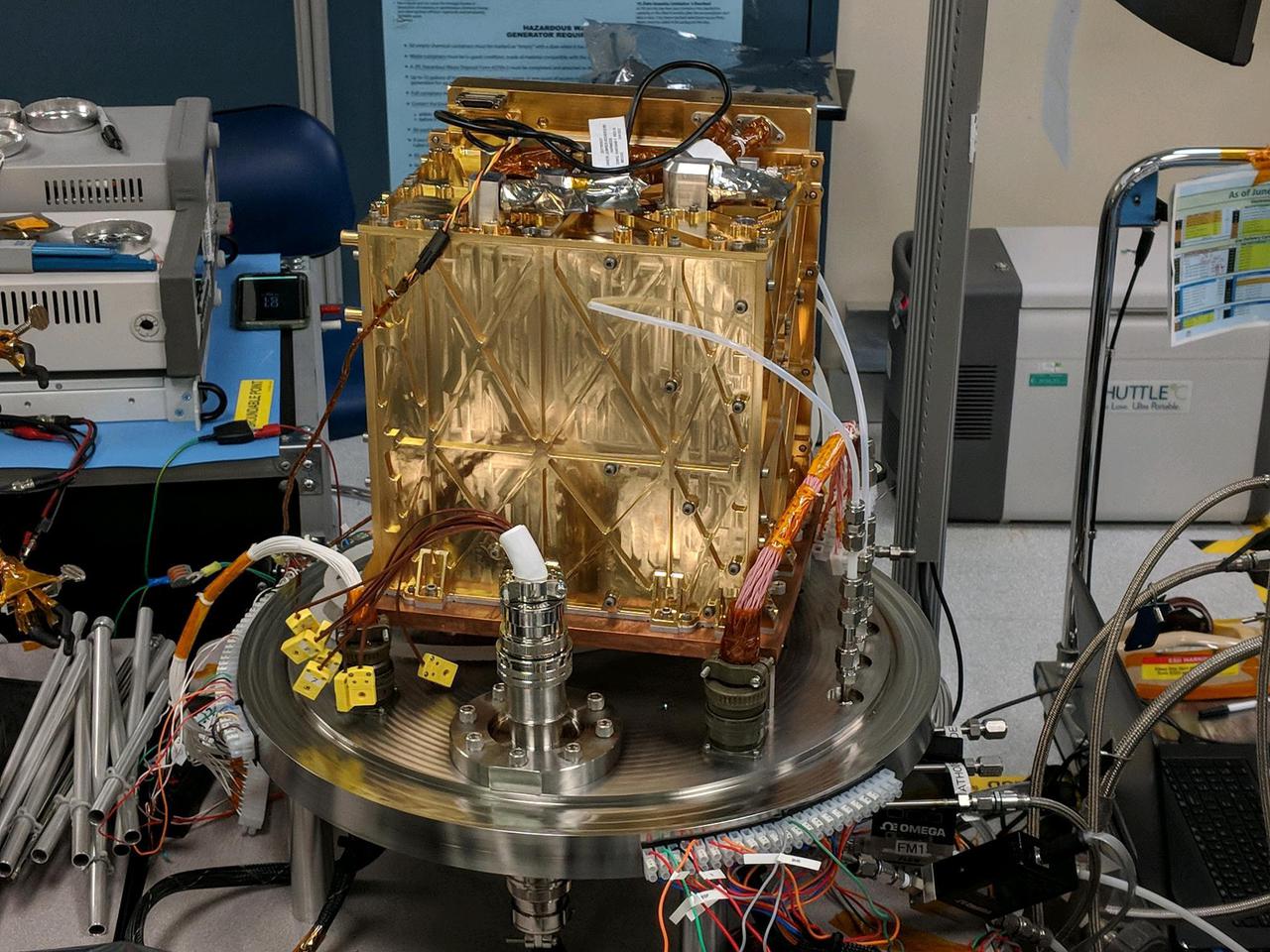
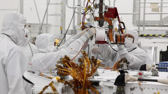
Engineers check cables on back of Aquarius instrument in the clean room at NASA Jet Propulsion Laboratory in Pasadena, Calif.
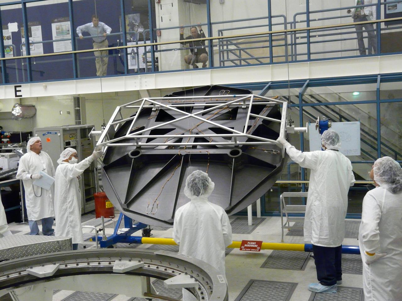
Engineers test Aquarius 2.5 meter reflector in the clean room at NASA Jet Propulsion Laboratory in Pasadena, Calif.
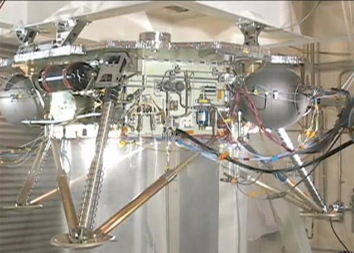
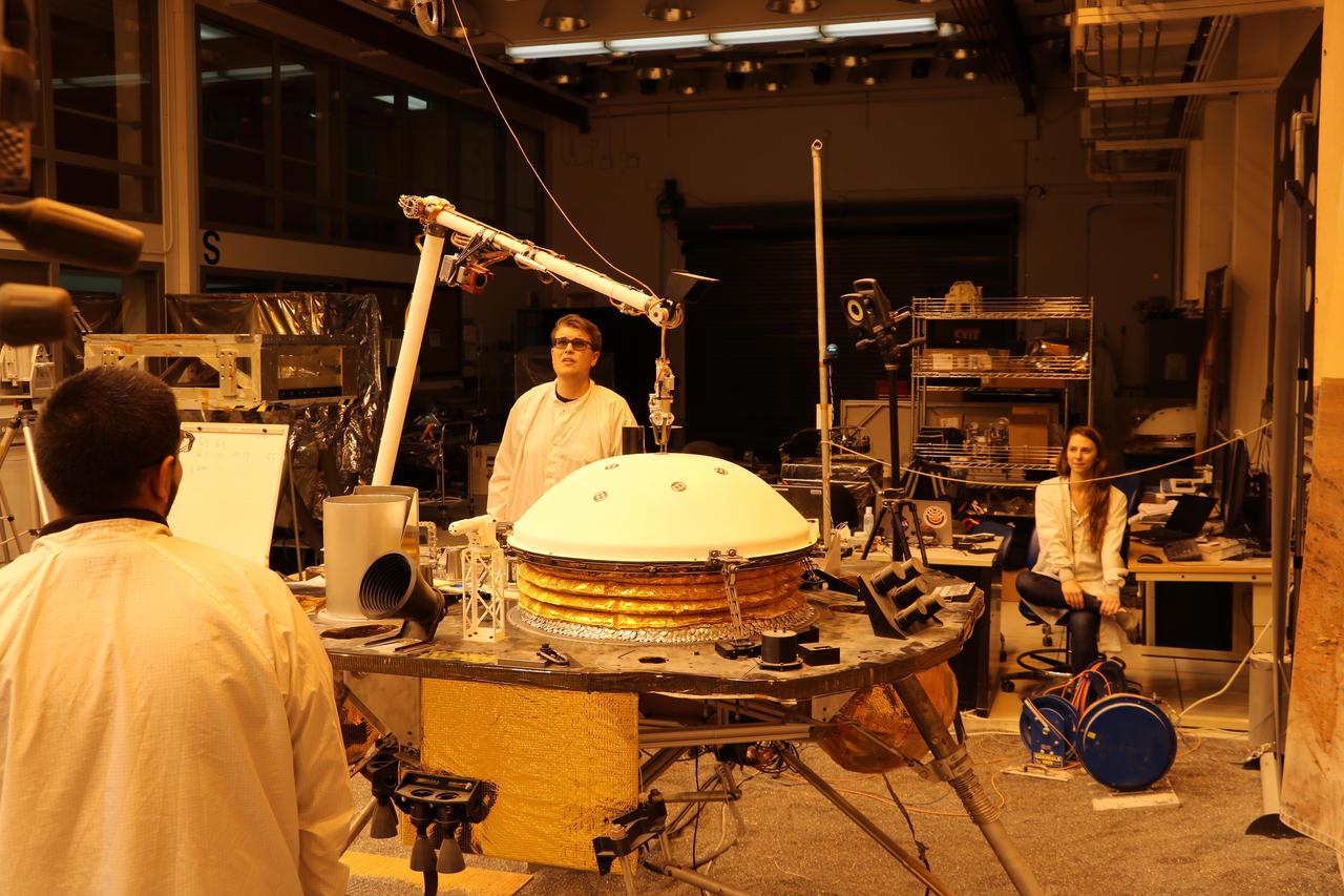
This video shows the propulsion system on an engineering model of NASA Phoenix Mars Lander being successfully tested.
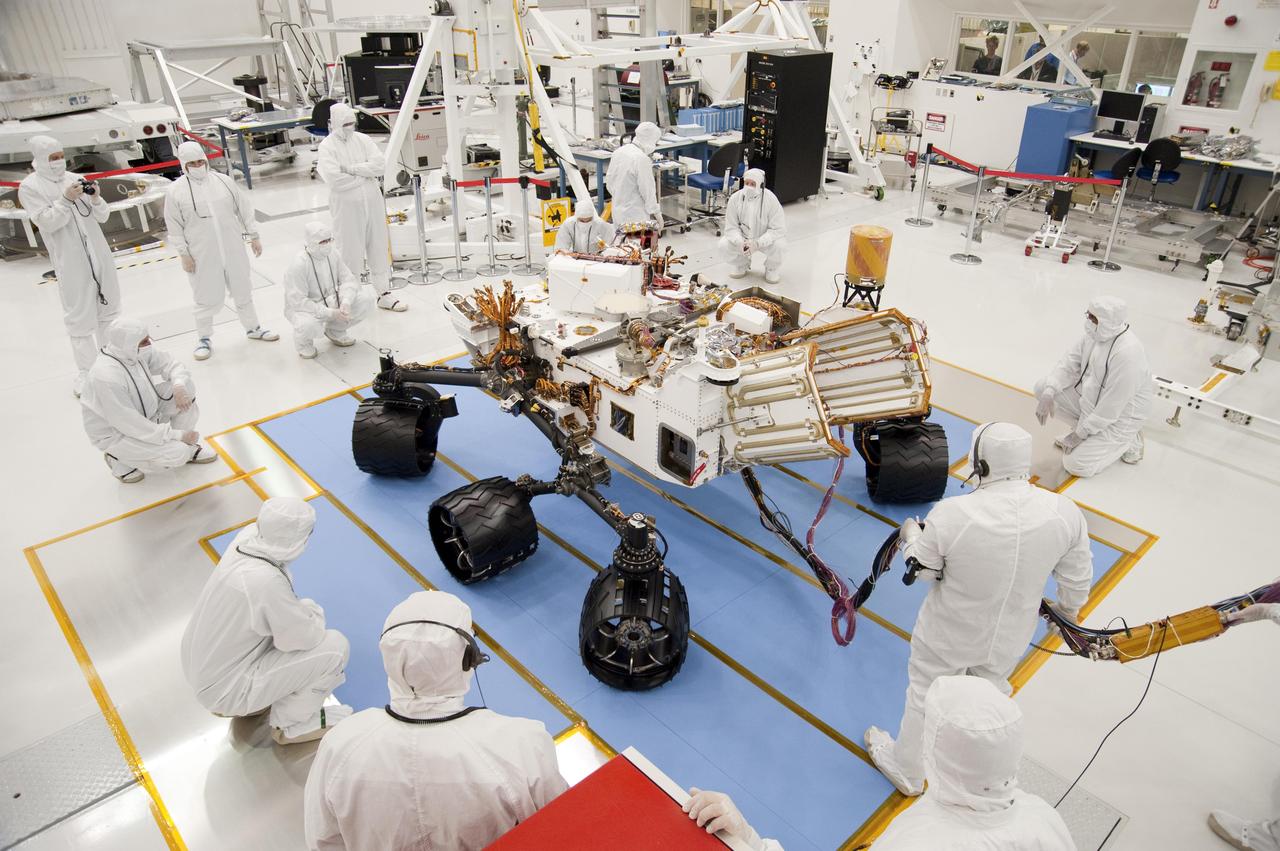
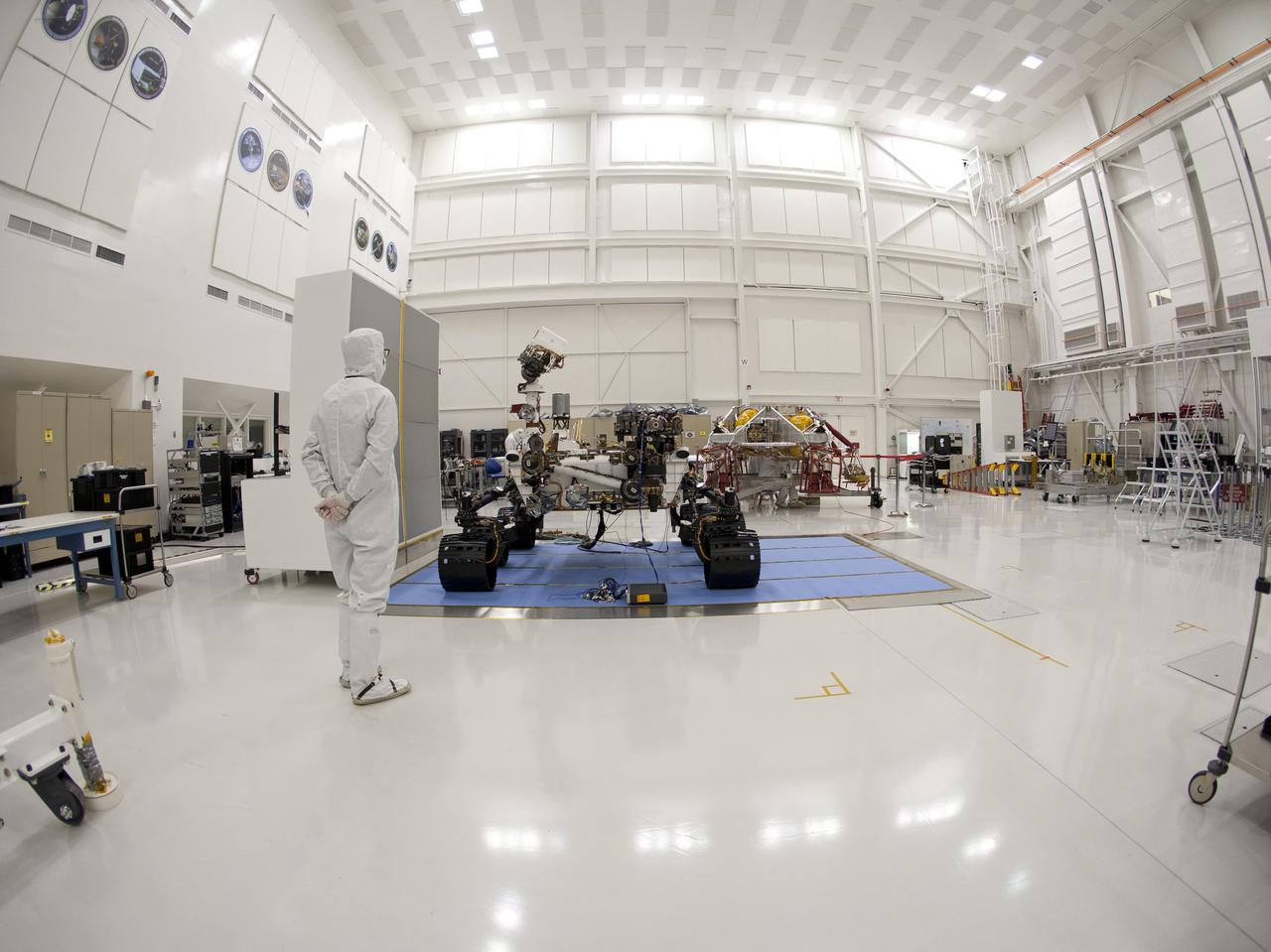
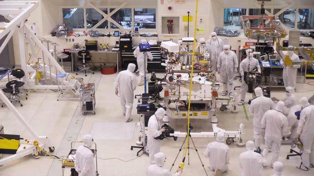
Technicians and engineers in clean-room garb monitor the first drive test of NASA Curiosity rover, on July 23, 2010. Technicians and engineers conducted the drive test at the Jet Propulsion Laboratory in Pasadena, Calif.
The Central Processing System at Glenn Research Center controls operations in the wind tunnels, propulsion systems lab, engine components research lab, and compressor, turbine and combustor test cells. Documentation photos of the facility were taken on December 19, 2023. Photo Credit: (NASA/Sara Lowthian-Hanna)
An engineer from NASA Jet Propulsion Laboratory oversees a fit check during the integration & testing of the Optical PAyload for Lasercomm Science OPALS.
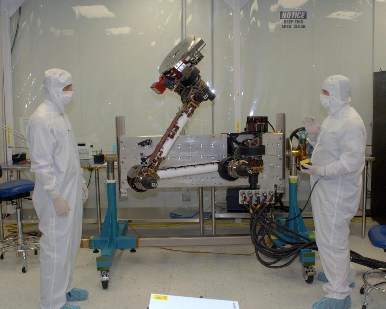
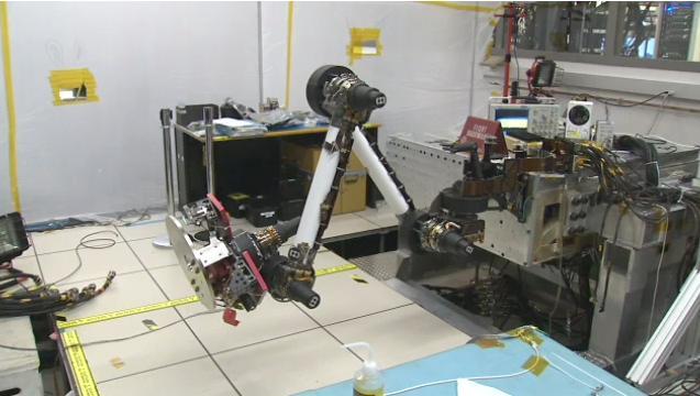
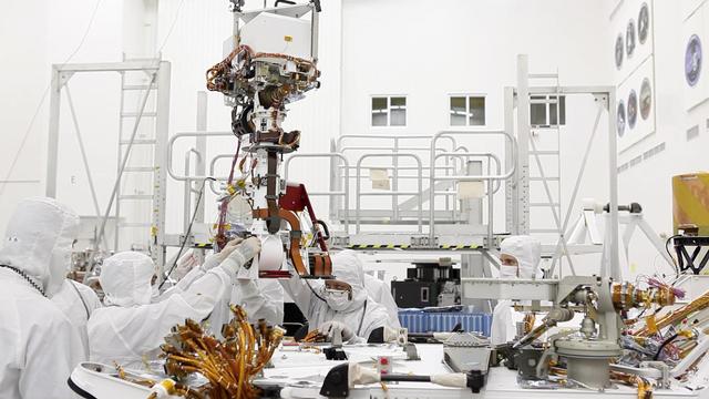
Engineers from NASA Jet Propulsion Laboratory and Alliance Spacesystems are testing the range of motion of the Mars Science Laboratory rover’s robotic arm joints.
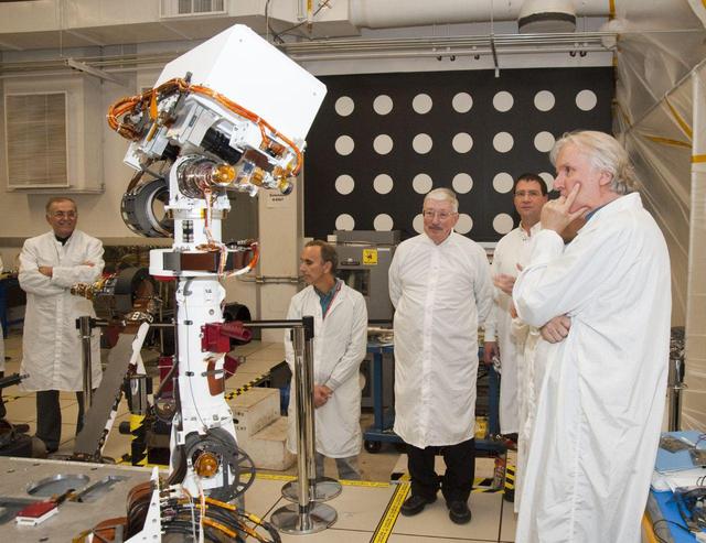
A group of members from the Jet Propulsion Laboratory watch the motions of an engineering model of the camera mast for NASA Mars rover Curiosity on March 5, 2010.

RoboSimian, a limbed robot developed by engineers at NASA Jet Propulsion Laboratory in Pasadena, California, competed in the DARPA Robotics Challenge Trials in Florida in December 2013.

RoboSimian, a limbed robot developed by engineers at NASA Jet Propulsion Laboratory in Pasadena, California, competed in the DARPA Robotics Challenge DRC Trials in Florida in December 2013.
In this image, engineers from NASA Jet Propulsion Laboratory test and flex Curiosity robotic arm and tools. A video can be viewed at the Photojournal.

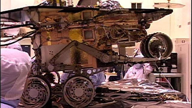
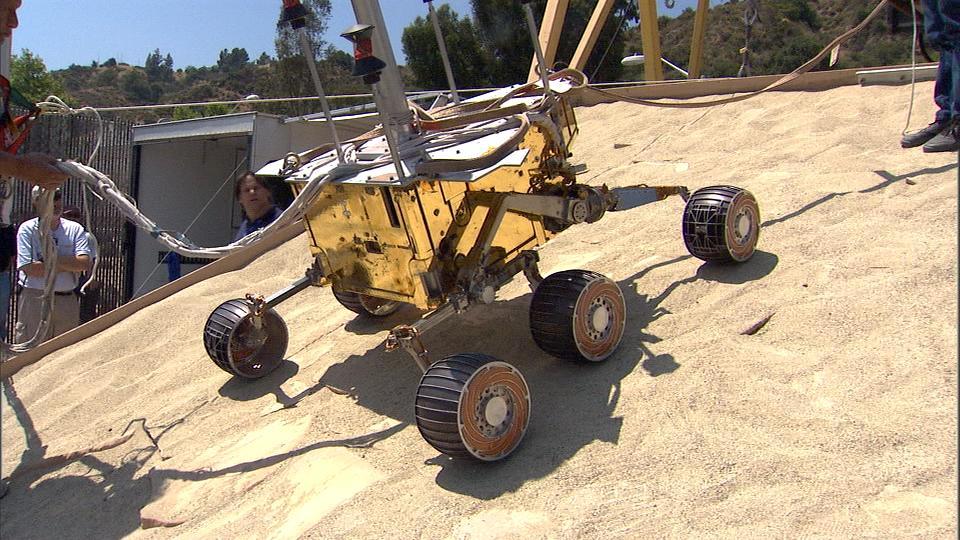
An engineering model for NASA Mars Science Laboratory makes its way up a hill in the Mars Yard testing area at NASA Jet Propulsion Laboratory.
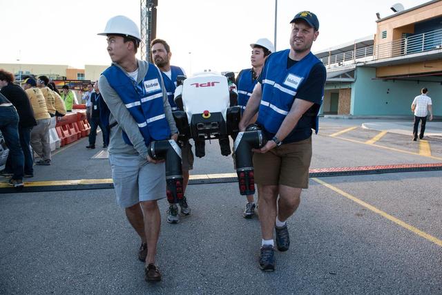
Engineers from NASA Jet Propulsion Laboratory carry RoboSimian, a robot developed at JPL, at the DARPA Robotics Challenge Trials in Florida in December 2013.
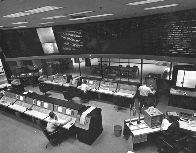
This archival image was released as part of a gallery comparing JPL's past and present, commemorating the 80th anniversary of NASA's Jet Propulsion Laboratory on Oct. 31, 2016. When spacecraft in deep space "phone home," they do it through NASA's Deep Space Network. Engineers in this room at NASA's Jet Propulsion Laboratory -- known as Mission Control -- monitor the flow of data. This image was taken in May 1964, when the building this nerve center is in, the Space Flight Operations Facility (Building 230), was dedicated at JPL. http://photojournal.jpl.nasa.gov/catalog/PIA21120
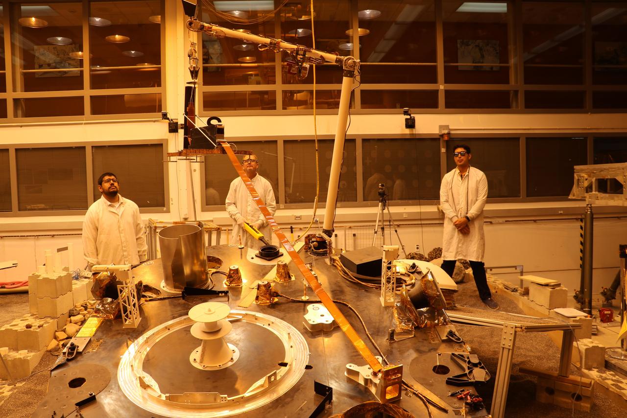
An engineering version of the robotic arm on NASA's InSight mission lifts the engineering version of the Heat Flow and Physical Properties Probe (HP3) at NASA's Jet Propulsion Laboratory. This test was conducted by InSight team members in a Mars-like environment, including reddish lighting, to simulate conditions InSight will encounter on the Red Planet. The orange tape-like tail behind HP3 is a tether that connects the HP3 support structure to the instrument's back-end electronics box on the lander. https://photojournal.jpl.nasa.gov/catalog/PIA22807
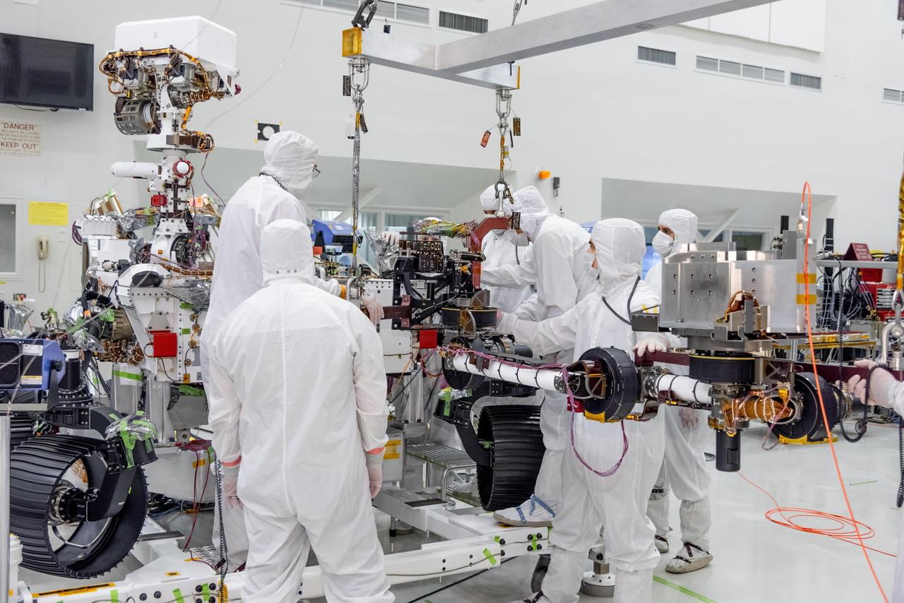
On June 21, 2019, engineers at NASA's Jet Propulsion Laboratory install the main robotic arm on the Mars 2020 rover. Measuring 7 feet (2.1 meters) long, the arm will allow the rover to work as a human geologist would: by holding and using science tools with its turret. https://photojournal.jpl.nasa.gov/catalog/PIA23227
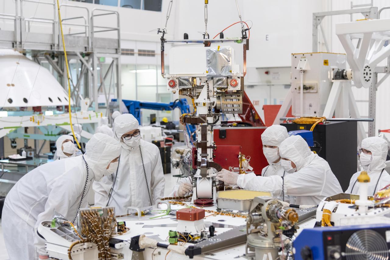
Engineers and technicians at NASA's Jet Propulsion Laboratory in Pasadena, California, install the remote sensing mast on the Mars 2020 rover. The image was taken on June 5, 2019, in the Spacecraft Assembly Facility's High Bay 1 clean room at JPL. https://photojournal.jpl.nasa.gov/catalog/PIA23268
Engineer Marleen Sundgaard watches as a test version of NASA's Mars InSight lander grasps a model of the spacecraft's seismometer. This work was done at NASA's Jet Propulsion Laboratory in Pasadena, California. https://photojournal.jpl.nasa.gov/catalog/PIA22952
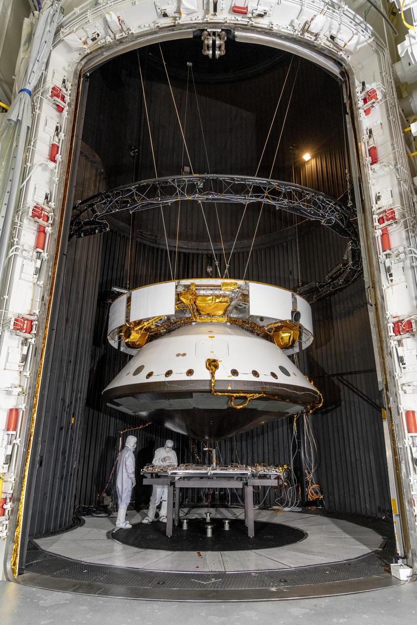
Engineers prepare the Mars 2020 spacecraft for a thermal vacuum (TVAC) test in the Space Simulator Facility at NASA's Jet Propulsion Laboratory in Pasadena, California. The image was taken on May 9, 2019. https://photojournal.jpl.nasa.gov/catalog/PIA23263
This archival photo shows engineers at NASA's Jet Propulsion Laboratory working on the 10-sided central structure, or "bus," of the Voyager 2 spacecraft on February 24,1977. https://photojournal.jpl.nasa.gov/catalog/PIA21478
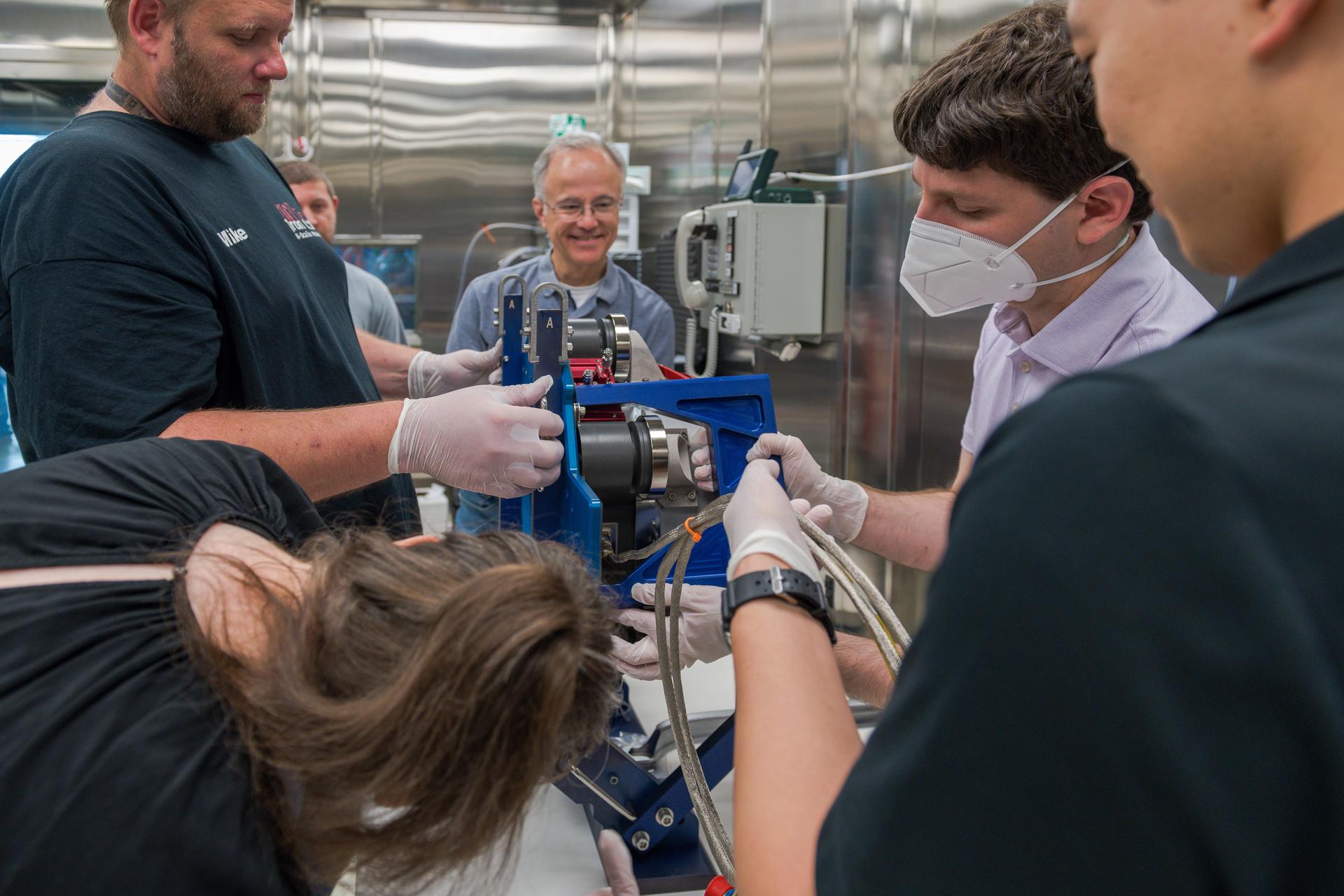
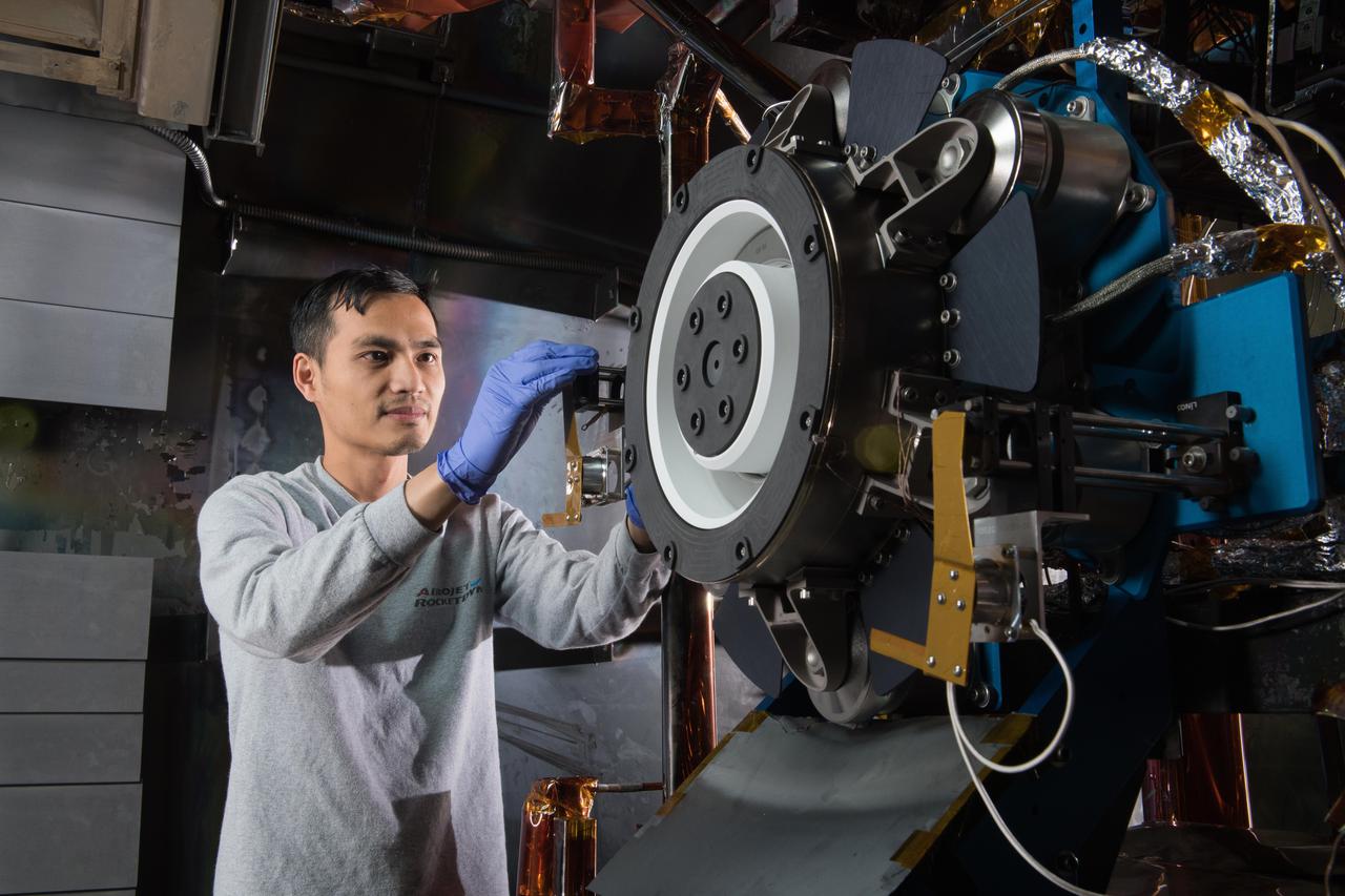
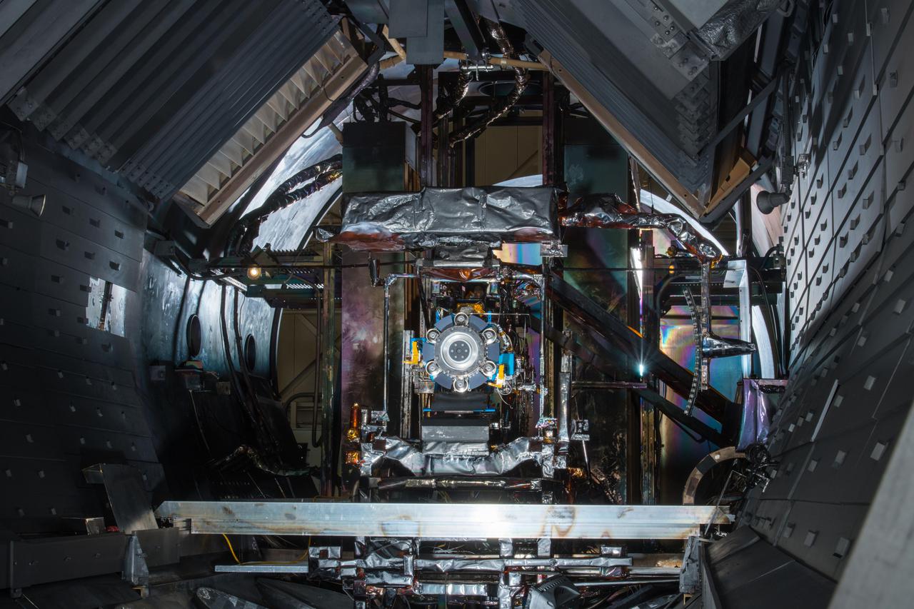
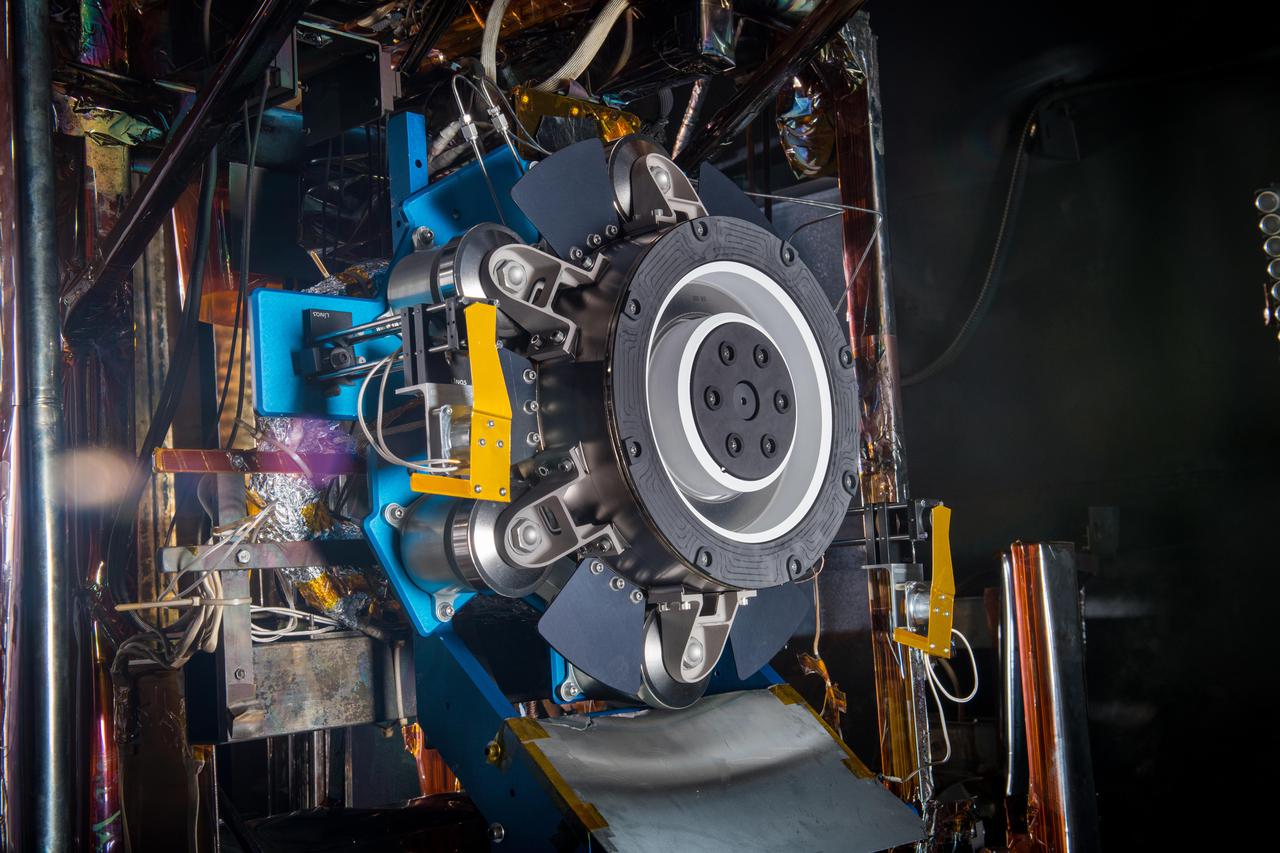
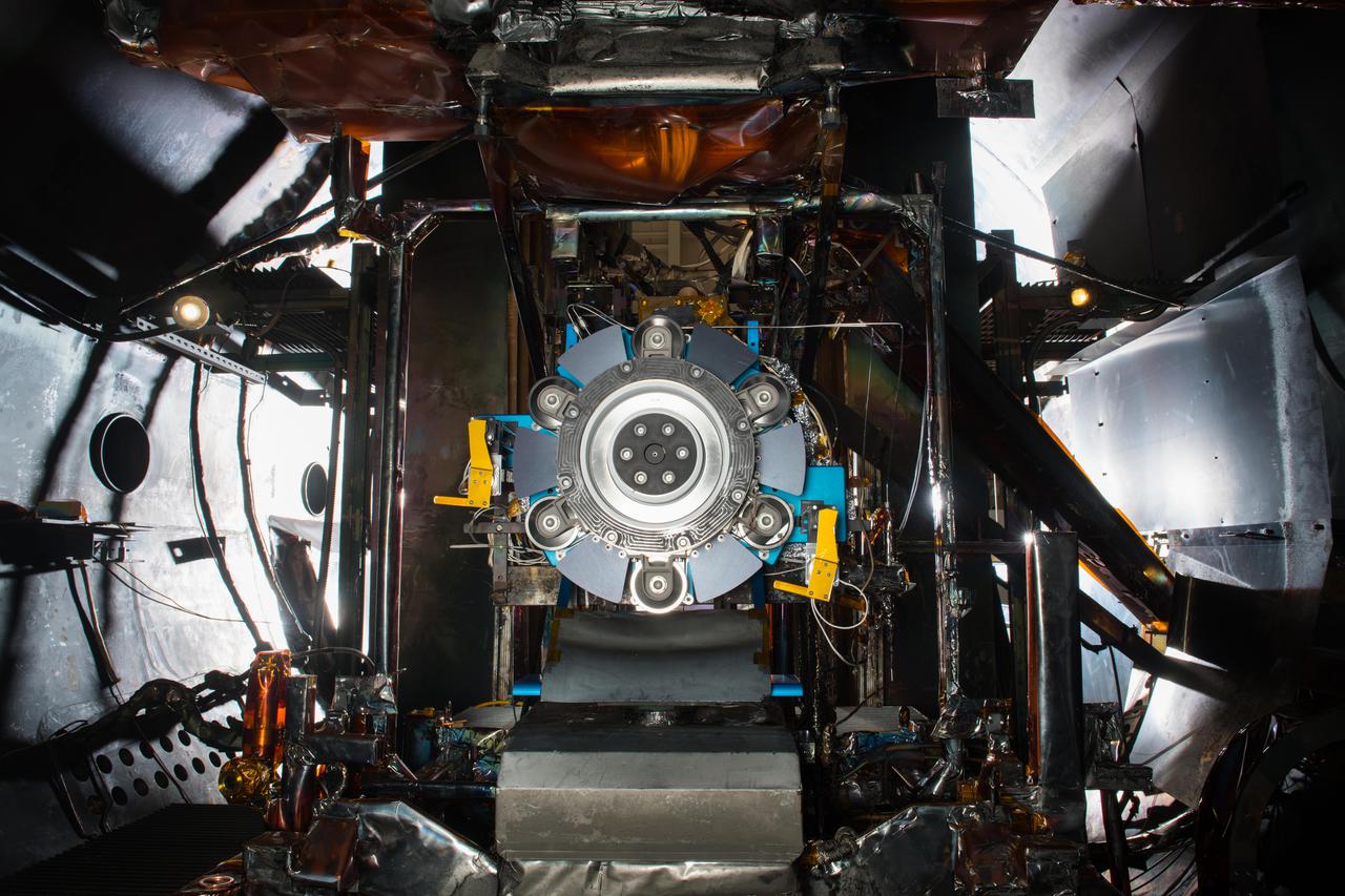
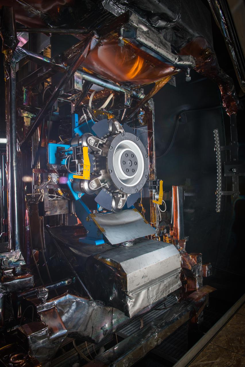
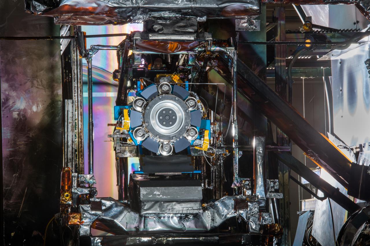
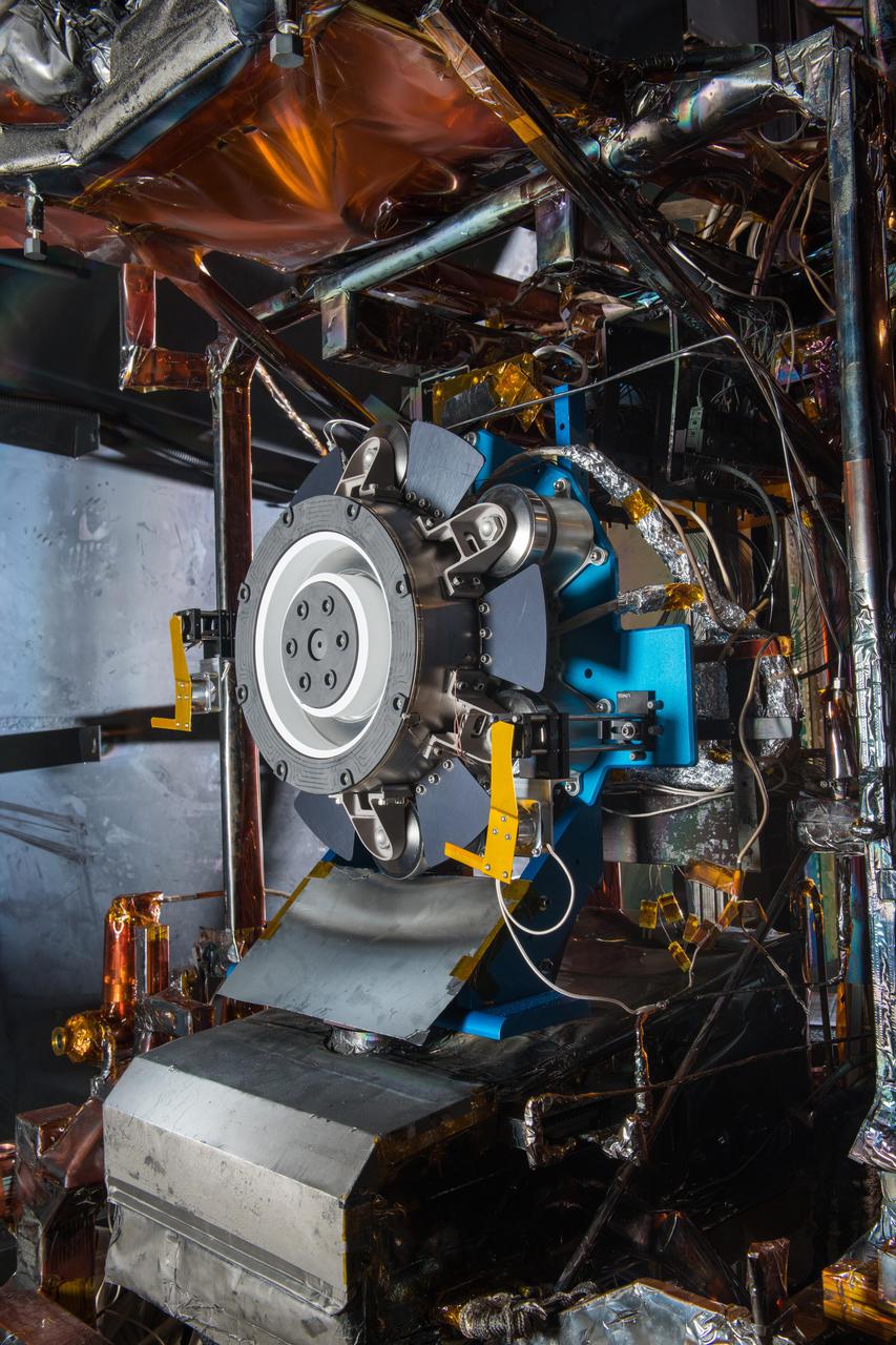
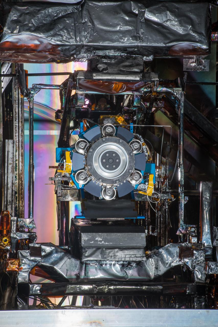
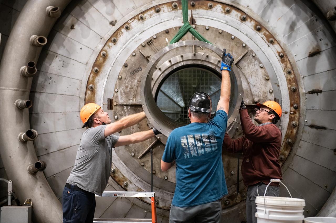
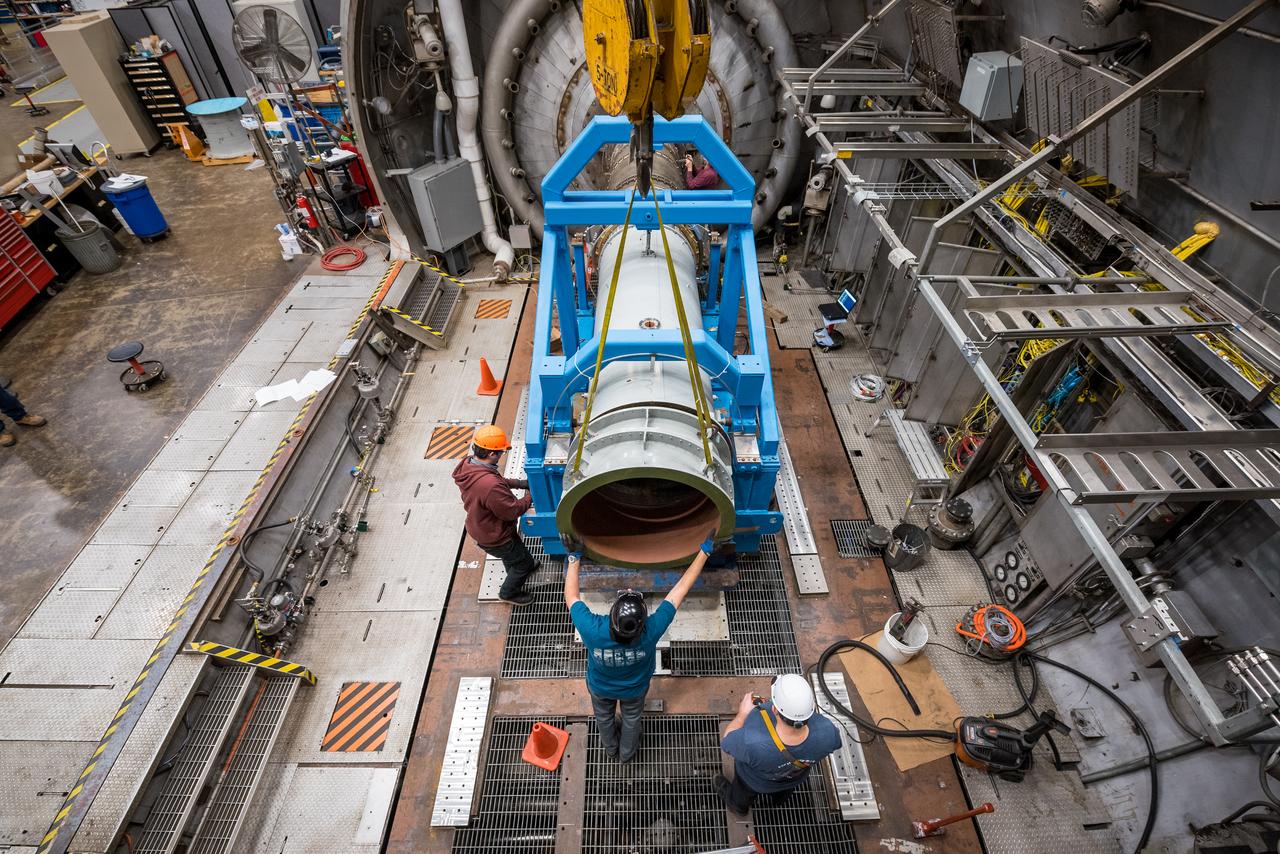
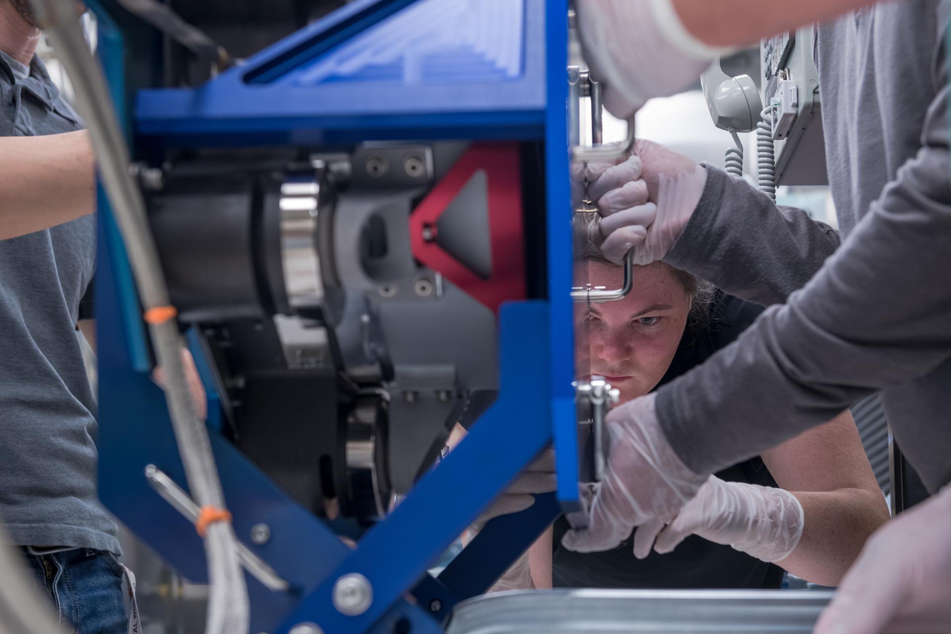
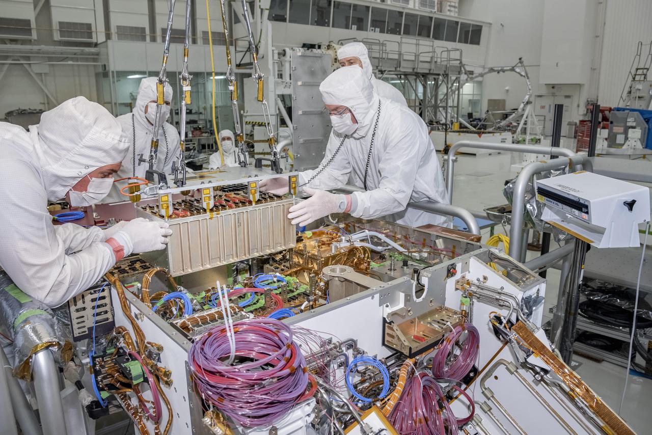
Engineers at NASA’s Glenn Research Center in Cleveland work together to position and secure the second of three Advanced Electric Propulsion System (AEPS) thrusters for acceptance testing. Following testing, the thruster was delivered to Lanteris Space Systems in Palo Alto, California, for installation on Gateway’s Power and Propulsion Element. Credit: NASA
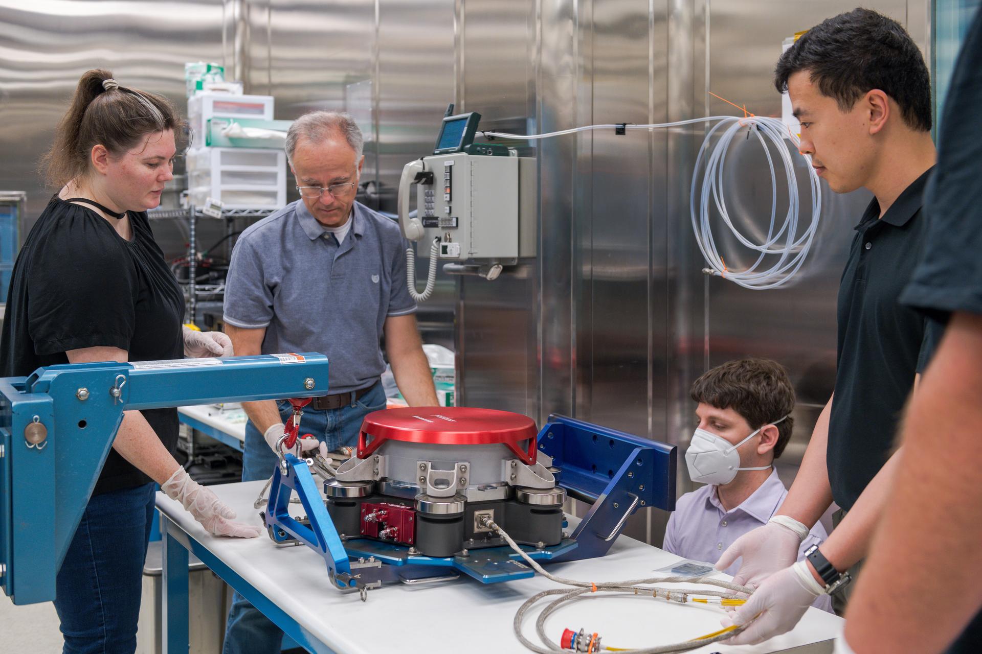
Engineers at NASA’s Glenn Research Center in Cleveland prepare the third and final Advanced Electric Propulsion System (AEPS) thruster for acceptance testing. Following successful testing, the thruster was delivered to Lanteris Space Systems in Palo Alto, California, for installation on the primary structure Gateway’s Power and Propulsion Element. Credit: NASA
Engineers at NASA’s Glenn Research Center in Cleveland work together to position and secure the second of three Advanced Electric Propulsion System (AEPS) thrusters for acceptance testing. Following testing, the thruster was delivered to Lanteris Space Systems in Palo Alto, California, for installation on Gateway’s Power and Propulsion Element. Credit: NASA
This engineering model of Mars Oxygen In-Situ Resource Utilization Experiment (MOXIE) instrument is about to undergo vibration testing in a lab at the Jet Propulsion Laboratory in Pasadena, California. Vibration tests demonstrate the ability of instruments to survive the extreme conditions of both a rocket launch from Earth and a landing on Mars. https://photojournal.jpl.nasa.gov/catalog/PIA24202
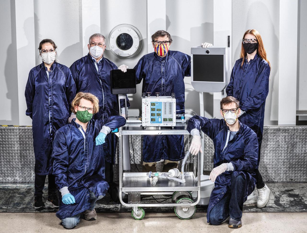
Some of the dozens of engineers involved in creating a ventilator prototype specially targeted to coronavirus disease patients at NASA's Jet Propulsion Laboratory in Southern California. Called VITAL (Ventilator Intervention Technology Accessible Locally), the prototype was created in 37 days in March and April 2020. https://photojournal.jpl.nasa.gov/catalog/PIA23713
In the clean room at NASA Jet Propulsion Laboratory, engineers gather around the base of Curiosity neck the Mast as they slowly lower it into place for attachment to the rover body the Wet Electronics Box, or WEB.
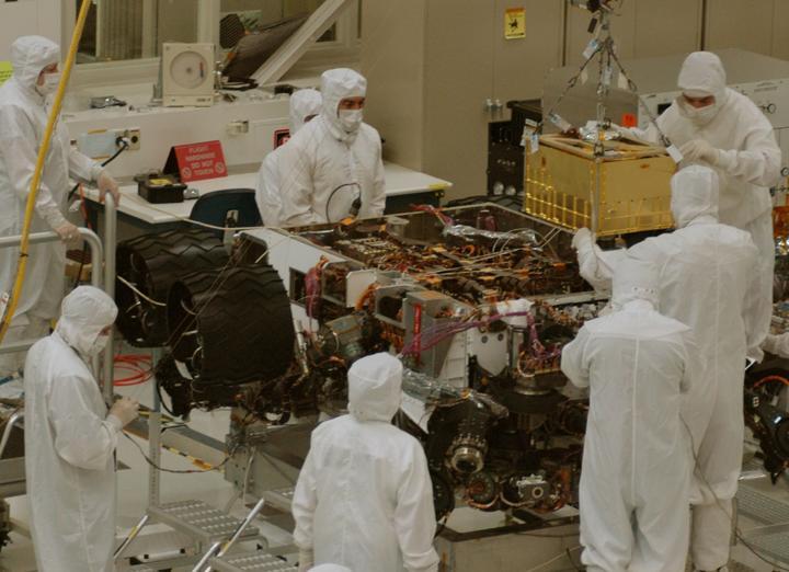
In this photograph, technicians and engineers inside a clean room at NASA Jet Propulsion Laboratory, Pasadena, Calif., position NASA Sample Analysis at Mars SAM above the mission Mars rover, Curiosity, for installing the instrument.
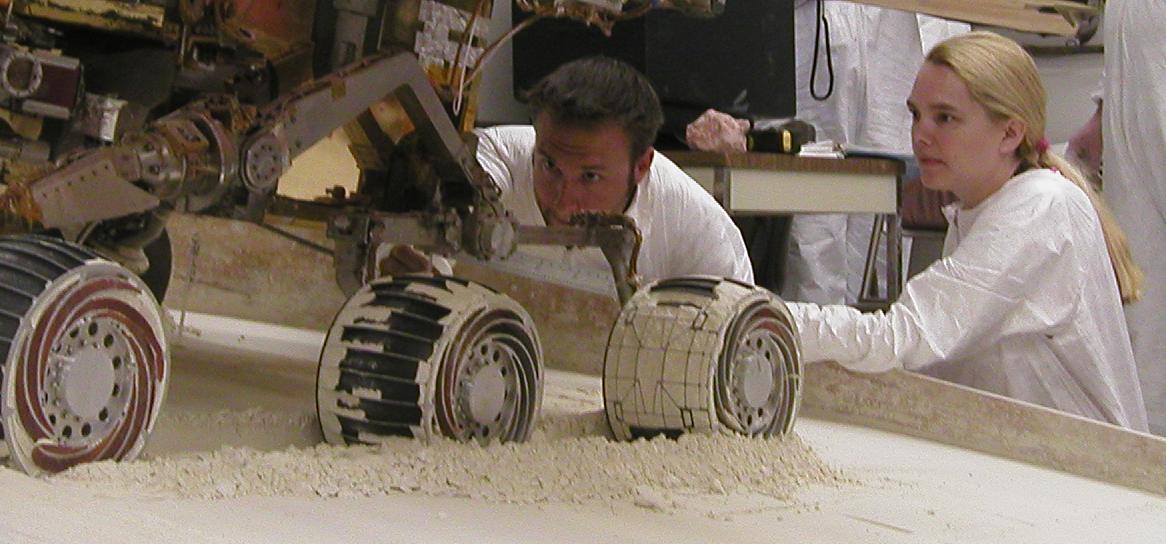
Rover engineers prepare a mixture of sandy and powdery materials to simulate some difficult Mars driving conditions inside a facility at NASA Jet Propulsion Laboratory, Pasadena, Calif.
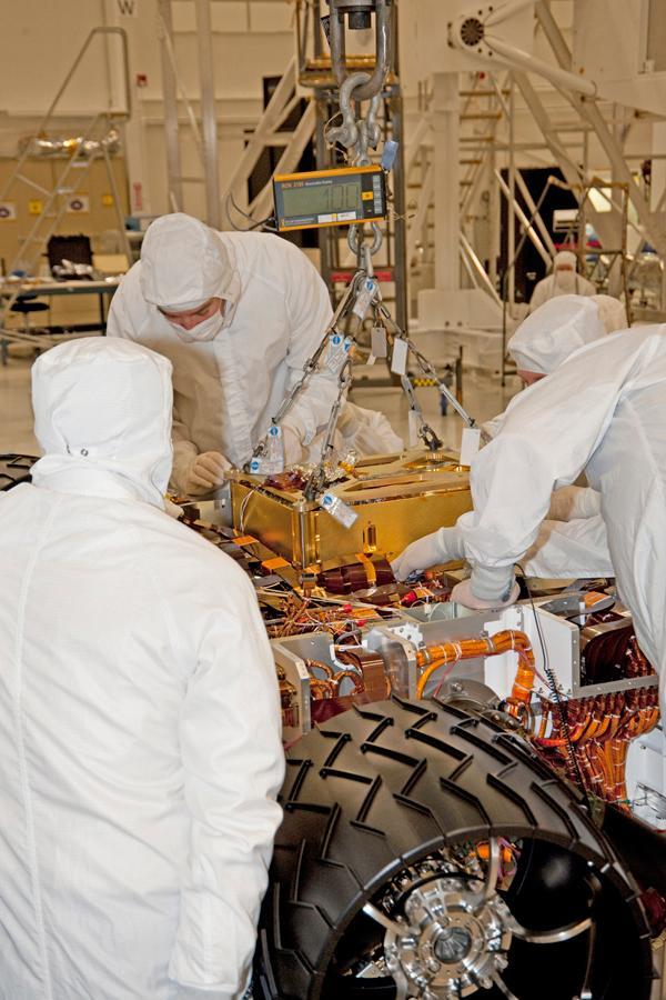
In this photograph, technicians and engineers inside a clean room at NASA Jet Propulsion Laboratory, Pasadena, Calif., position NASA Sample Analysis at Mars SAM above the mission Mars rover, Curiosity, for installing the instrument.
Rover engineers check how a test rover moves in material chosen to simulate some difficult Mars driving conditions. The scene is inside the In-Situ Instrument Laboratory at NASA Jet Propulsion Laboratory, Pasadena, Calif.
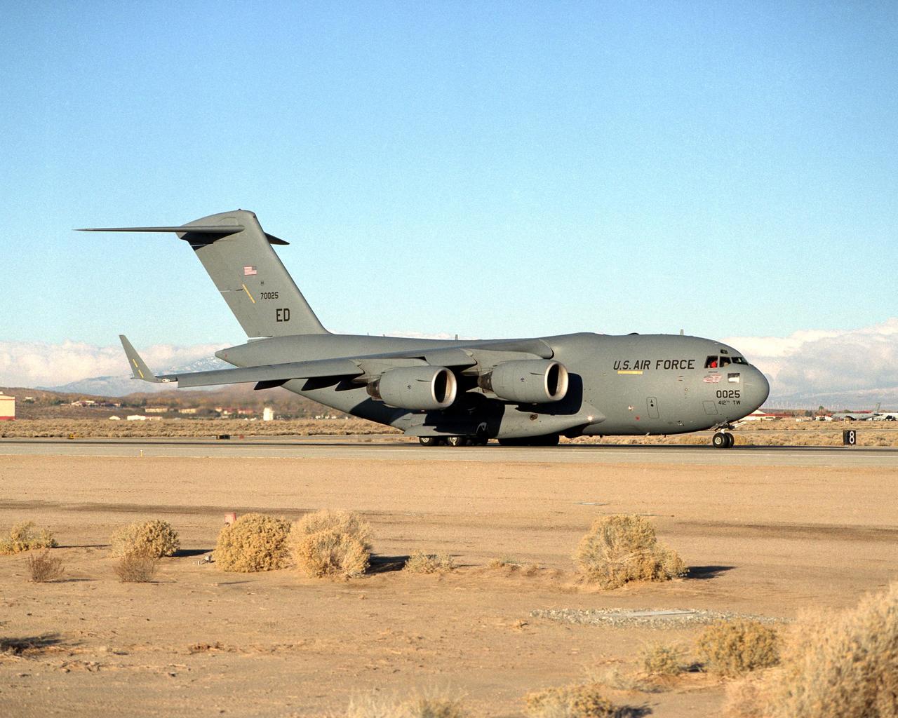
The Air Force provided a C-17 Globemaster III for use in the Vehicle Integrated Propulsion Research (VIPR) effort. Researchers are using the airplane for ground testing of new engine health monitoring technologies.
Engineers at NASA Jet Propulsion Laboratory are dressed head to toe in bunny suits only their eyes and foreheads can be seen. They are huddled around the base of the rover Curiosity neck its Mast.

Rover engineers check how a test rover moves in material chosen to simulate some difficult Mars driving conditions. The scene is inside the In-Situ Instrument Laboratory at NASA Jet Propulsion Laboratory, Pasadena, Calif.
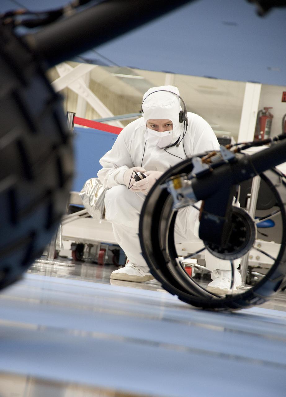
A test operator in clean-room garb observes rolling of the wheels during the first drive test of NASA Curiosity rover, on July 23, 2010. Technicians and engineers conducted the drive test at the Jet Propulsion Laboratory in Pasadena, Calif.
An engineer says goodbye to the Curiosity rover and its powered descent vehicle in the Jet Propulsion Laboratory Spacecraft Assembly Facility shortly before the spacecraft was readied for shipment to Kennedy Space Center for launch.
This image taken at NASA Jet Propulsion Laboratory shows engineers testing the rover stand-up motions. The rover is in an elevated pose, preparing to fold down its wheels, descend and stand up.
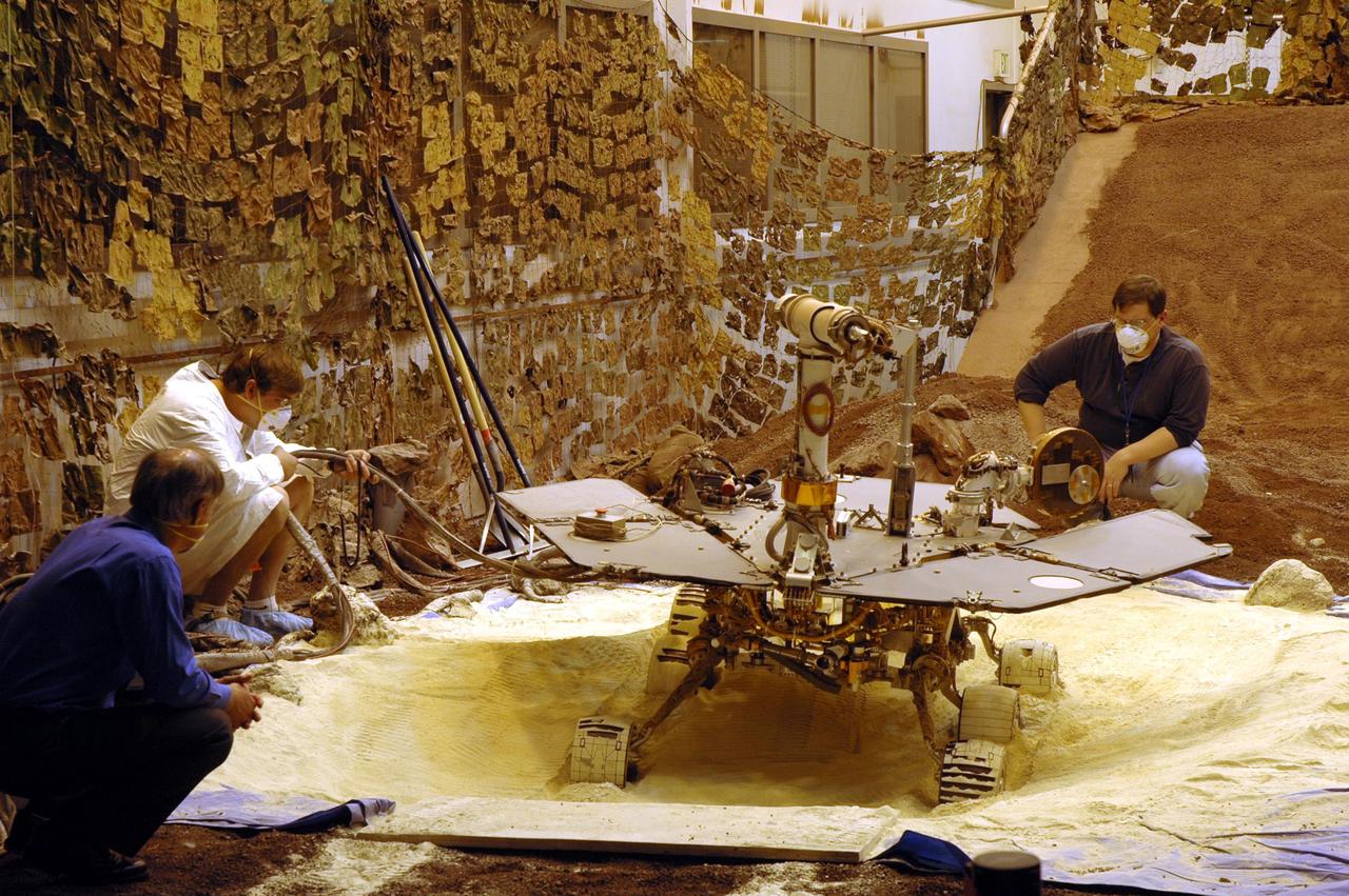
Mike Seibert and Sharon Laubach, engineers on NASA Mars Exploration Rover team at the Jet Propulsion Laboratory, Pasadena, check the exact position of a test rover in preparation for the next test of a possible maneuver for Spirit to use on Mars.
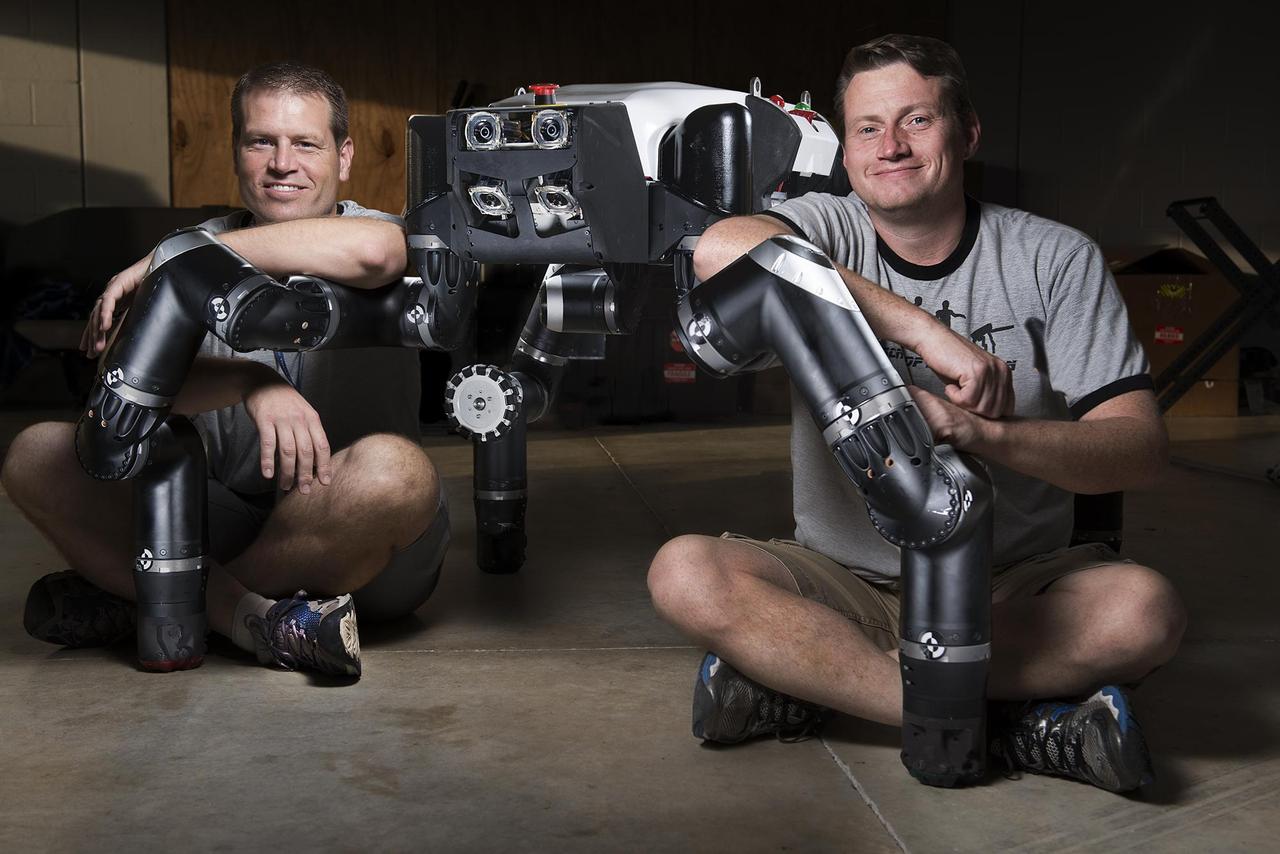
Limbed robot RoboSimian was developed at NASA Jet Propulsion Laboratory, seen here with Brett Kennedy, supervisor of the JPL Robotic Vehicles and Manipulators Group, and Chuck Bergh, a senior engineer in JPL Robotic Hardware Systems Group.
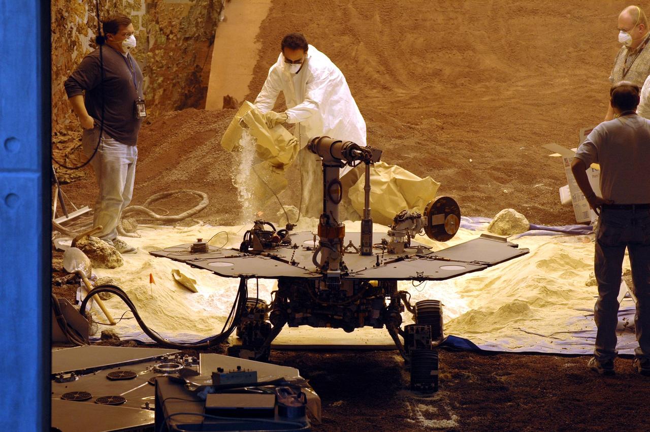
This image taken at NASA Jet Propulsion Laboratory shows engineers rehearsing the sol 133 June 8, 2004 drive into Endurance crater by NASA Mars Exploration Rover Opportunity.
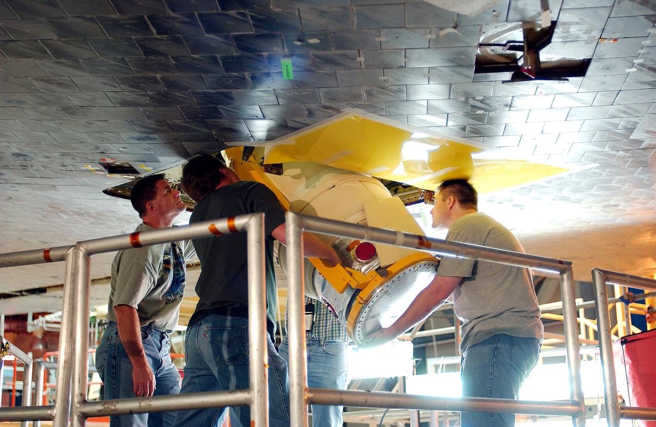
KENNEDY SPACE CENTER, FLA. - Workers in the Orbiter Processing Facility insert the liquid oxygen feedline for the 17-inch disconnect in the orbiter Discovery. The 17-inch liquid oxygen and liquid hydrogen disconnects provide the propellant feed interface from the external tank to the orbiter main propulsion system and the three Shuttle main engines.
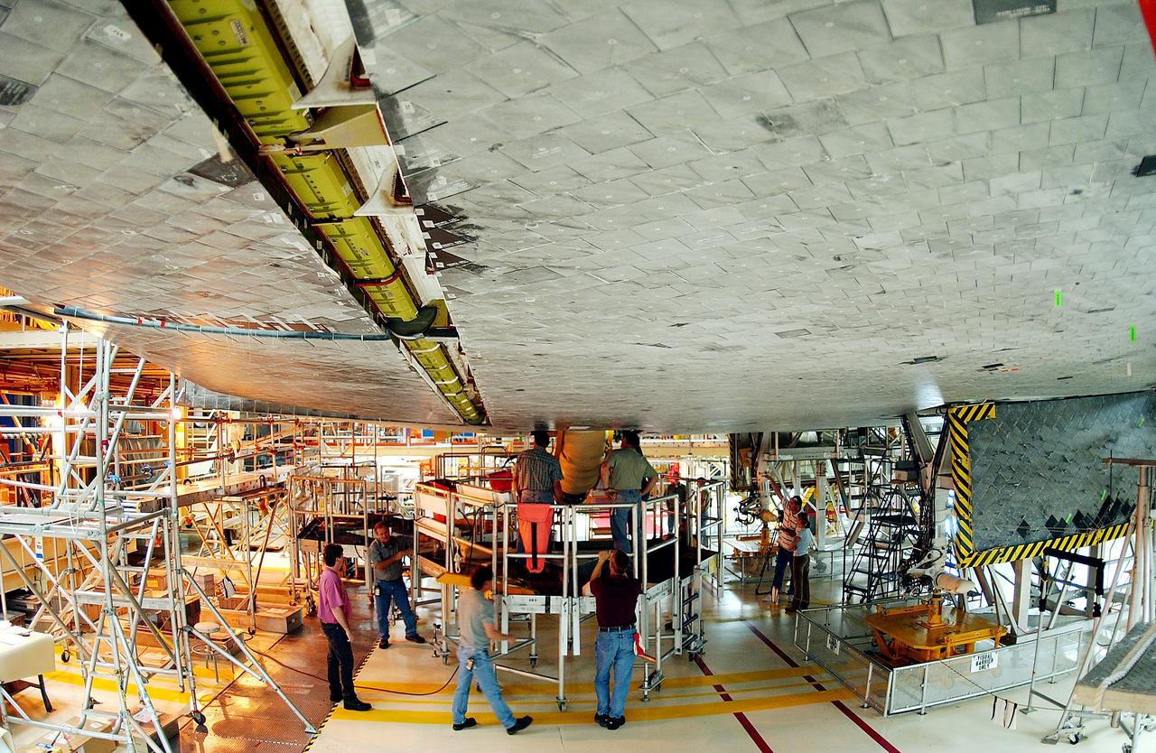
KENNEDY SPACE CENTER, FLA. - Workers in the Orbiter Processing Facility oversee installation of the liquid oxygen feedline for the 17-inch disconnect on the orbiter Discovery. The 17-inch liquid oxygen and liquid hydrogen disconnects provide the propellant feed interface from the external tank to the orbiter main propulsion system and the three Shuttle main engines.
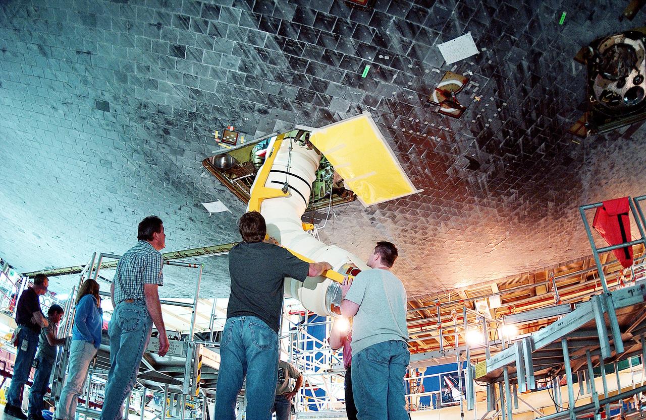
KENNEDY SPACE CENTER, FLA. - In the Orbiter Processing Facility, workers install the liquid oxygen feedline for the 17-inch disconnect on orbiter Discovery. The 17-inch liquid oxygen and liquid hydrogen disconnects provide the propellant feed interface from the external tank to the orbiter main propulsion system and the three Shuttle main engines.

KENNEDY SPACE CENTER, FLA. - Workers in the Orbiter Processing Facility insert the liquid oxygen feedline for the 17-inch disconnect in the orbiter Discovery. The 17-inch liquid oxygen and liquid hydrogen disconnects provide the propellant feed interface from the external tank to the orbiter main propulsion system and the three Shuttle main engines.
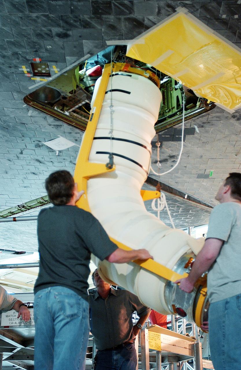
KENNEDY SPACE CENTER, FLA. - In the Orbiter Processing Facility, workers install the liquid oxygen feedline for the 17-inch disconnect on orbiter Discovery. The 17-inch liquid oxygen and liquid hydrogen disconnects provide the propellant feed interface from the external tank to the orbiter main propulsion system and the three Shuttle main engines.

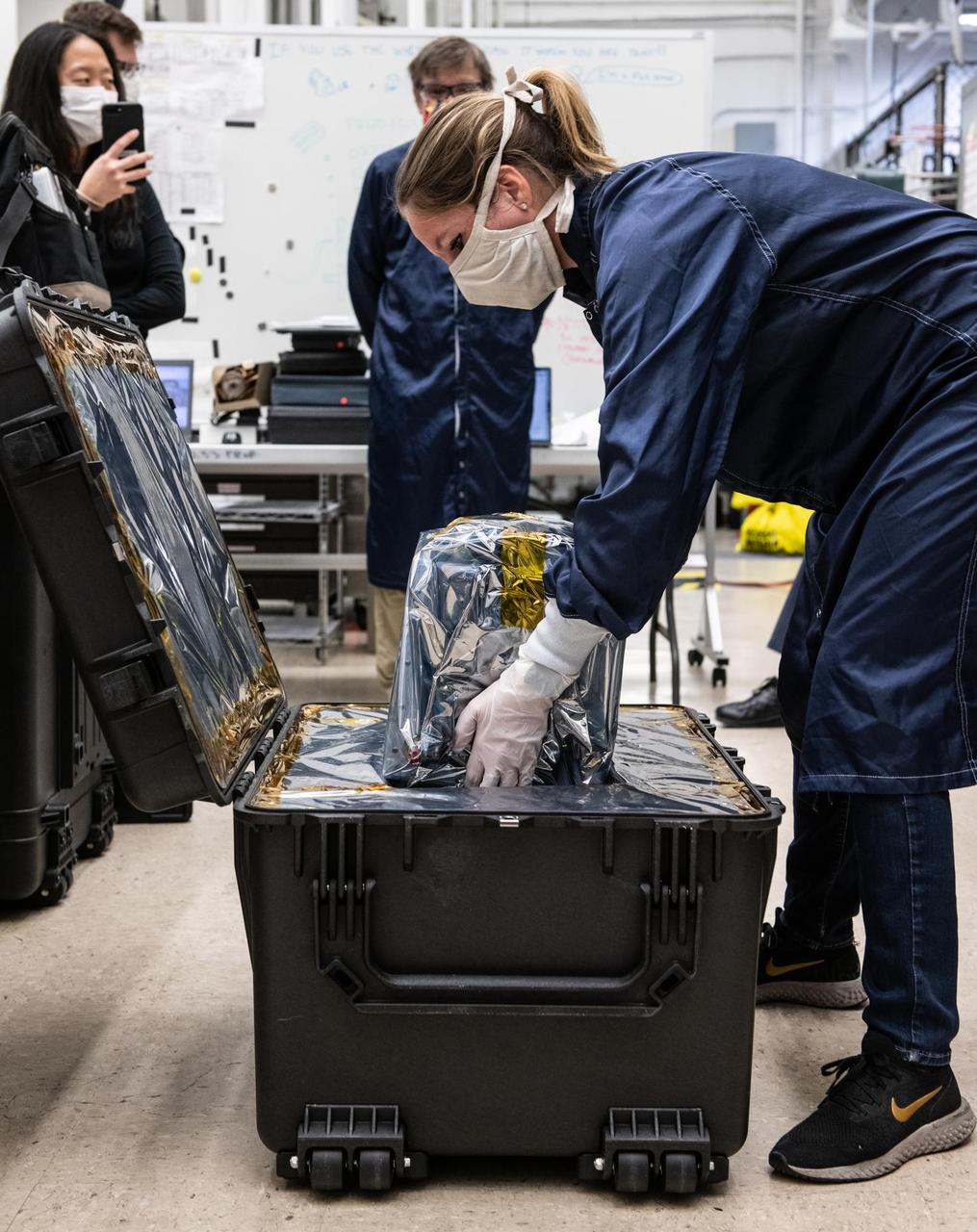
Engineers at the Johns Hopkins Applied Physics Laboratory (APL) in Laurel, Maryland, inspect the propulsion module of NASA's Europa Clipper spacecraft. In 2022, this major piece of hardware, designed and built at APL, will ship to NASA's Jet Propulsion Laboratory in Southern California for assembly, test, and launch operations (ATLO). With an internal global ocean under a thick layer of ice, Jupiter's moon Europa may have the potential to harbor existing life. The Europa Clipper spacecraft will swoop around Jupiter on an elliptical path, dipping close to the moon on each flyby to collect data. Understanding Europa's habitability will help scientists better understand how life developed on Earth and the potential for finding life beyond our planet. Europa Clipper is set to launch in 2024. https://photojournal.jpl.nasa.gov/catalog/PIA24783
NASA's InSight mission tests an engineering version of the spacecraft's robotic arm in a Mars-like environment at NASA's Jet Propulsion Laboratory. The five-fingered grapple on the end of the robotic arm is lifting up the Wind and Thermal Shield, a protective covering for InSight's seismometer. The test is being conducted under reddish "Mars lighting" to simulate activities on the Red Planet. https://photojournal.jpl.nasa.gov/catalog/PIA22806
A team of engineers at NASA's Jet Propulsion Laboratory in Pasadena, California, install the legs and wheels — otherwise known as the mobility suspension — on the Mars 2020 rover. The imagery for this accelerated time-lapse was taken on June 13, 2019, from a camera above the Spacecraft Assembly Facility's High Bay 1 clean room. https://photojournal.jpl.nasa.gov/catalog/PIA23261

Engineers at NASA's Jet Propulsion Laboratory – from left, Brandon Creager, Juan Gloria, Joshua Nachtigal, and Sonny Gutierrez – are shown assembling the electronics palette for the Coronagraph Instrument on NASA's Roman Space Telescope in December 2022. One of two main sections of the instrument, this layer houses the instrument electronics that receive instructions from the Roman spacecraft and send back the Coronagraph Instrument's scientific data. The electronics also control the mechanical components on the optical bench and the instrument heaters. https://photojournal.jpl.nasa.gov/catalog/PIA25435
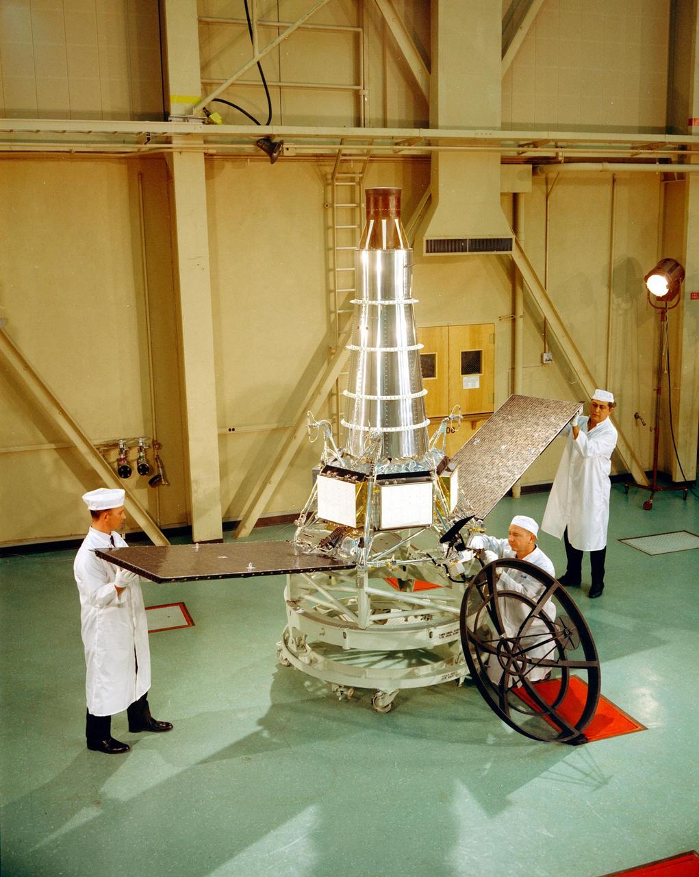
Engineers stand with Ranger 7 on Dec. 10, 1963, in High Bay 1, located at NASA's Jet Propulsion Laboratory. Ranger 7 was the first U.S. mission to transmit images from the surface of the Moon. The Ranger program included a series of robotic spacecraft launched at the Moon. JPL developed the art of spacecraft assembly and testing with each iteration of the Ranger spacecraft. https://photojournal.jpl.nasa.gov/catalog/PIA23520
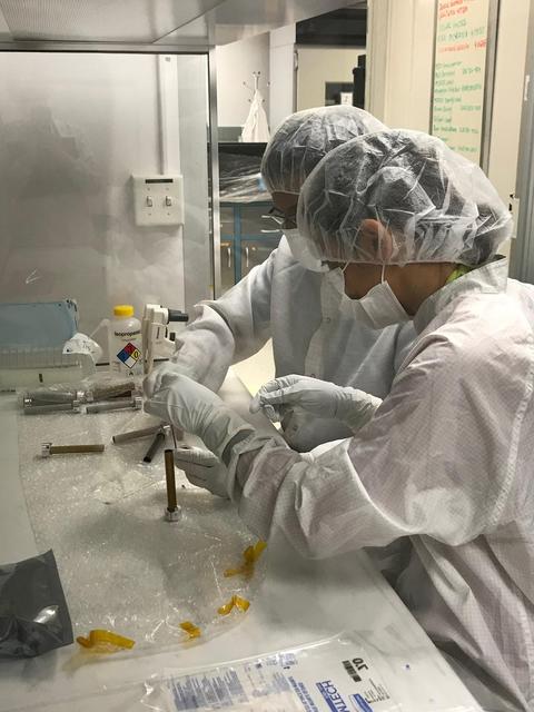
Planetary protection engineers at NASA's Jet Propulsion Laboratory in Southern California swab engineering models of the tubes that will store Martian rock and sediment samples as part of NASA’s Mars 2020 Perseverance mission. Team members wanted to understand the transport of biological particles when the rover is taking rock cores. These measurements helped the rover team design hardware and sampling methods that meet stringent biological contamination control requirements. https://photojournal.jpl.nasa.gov/catalog/PIA23718
Engineers at NASA's Jet Propulsion Laboratory in Southern California prepare to ship a prototype ventilator for coronavirus patients to the Icahn School of Medicine at Mount Sinai in New York. VITAL (Ventilator Intervention Technology Accessible Locally) is designed to be faster to build and easier to maintain than traditional ventilators, with a fraction of the parts. JPL engineers created the prototype specially targeted at COVID-19 patients in 37 days in March and April 2020. https://photojournal.jpl.nasa.gov/catalog/PIA23716
This archival image was released as part of a gallery comparing JPL's past and present, commemorating the 80th anniversary of NASA's Jet Propulsion Laboratory on Oct. 31, 2016. This image shows engineers at NASA's Jet Propulsion Laboratory looking at data related to the Venus flyby of Mariner 2 on Dec. 14, 1962. This was the first successful flyby of another planet. http://photojournal.jpl.nasa.gov/catalog/PIA21117

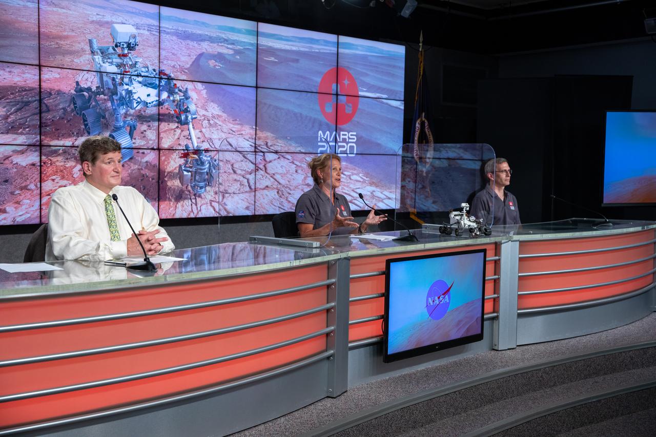
DC Agle, with NASA’s Jet Propulsion Laboratory, moderates a Mars 2020 Mission Engineering and Science Briefing at NASA’s Kennedy Space Center in Florida on July 27, 2020. The Mars Perseverance rover is scheduled to launch July 30, on a United Launch Alliance Atlas V 541 rocket from Space Launch Complex 41 at nearby Cape Canaveral Air Force Station. The rover is part of NASA’s Mars Exploration Program, a long-term effort of robotic exploration of the Red Planet. The rover will search for habitable conditions in the ancient past and signs of past microbial life on Mars. The Launch Services Program at Kennedy is responsible for launch management.
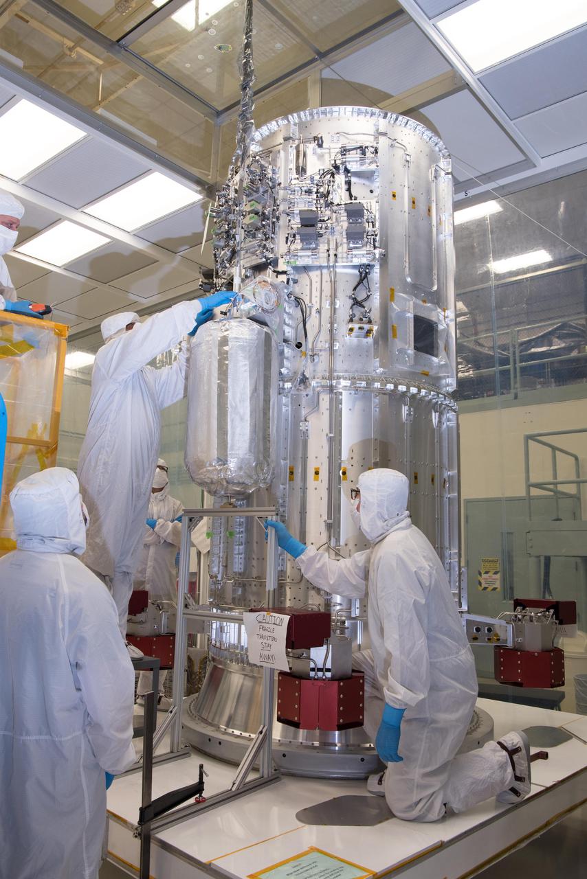
Engineers and technicians in a clean room at NASA's Goddard Space Flight Center in Greenbelt, Maryland, integrate the tanks that will contain helium onto the propulsion module of NASA's Europa Clipper spacecraft. The 10-foot-tall (3-meter-tall) propulsion module was also integrated with 16 rocket engines at Goddard. The module then was shipped to the Johns Hopkins Applied Physics Laboratory (APL) in Laurel, Maryland, where engineers will install electronics, radios, antennas, and cabling. In 2022, this major piece of hardware will ship to NASA's Jet Propulsion Laboratory in Southern California for assembly, test, and launch operations. With an internal global ocean under a thick layer of ice, Jupiter's moon Europa may have the potential to harbor existing life. The Europa Clipper spacecraft will swoop around Jupiter on an elliptical path, dipping close to the moon on each flyby to collect data. Understanding Europa's habitability will help scientists better understand how life developed on Earth and the potential for finding life beyond our planet. Europa Clipper is set to launch in 2024. https://photojournal.jpl.nasa.gov/catalog/PIA24782
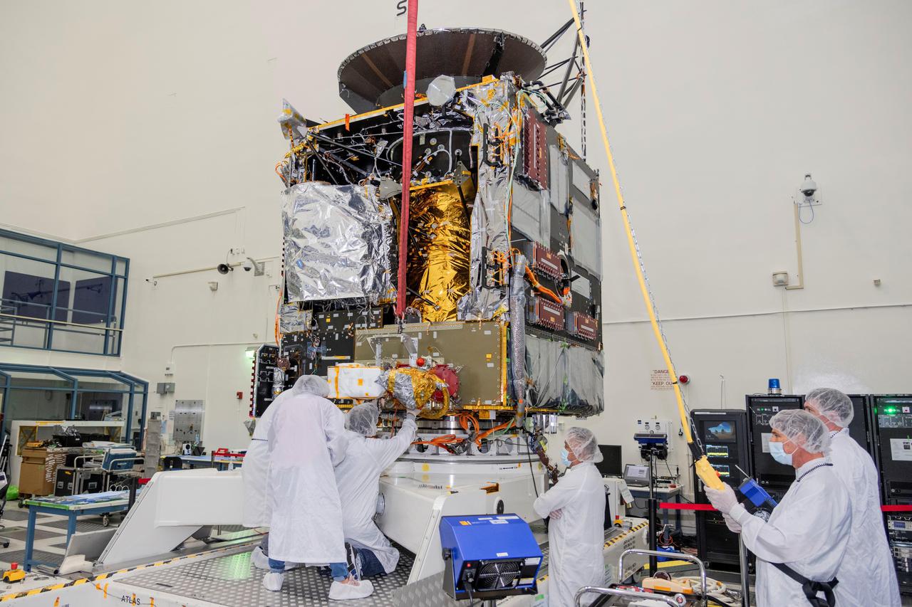
Engineers at NASA's Jet Propulsion Laboratory in Southern California work to integrate Hall thrusters into the agency's Psyche spacecraft in this July 2021 photo. One of the thrusters is visible on the side of the spacecraft beneath a red protective cover. Psyche is set to launch in August 2022 and will travel to its target, a metal-rich asteroid also named Psyche, under the power of solar electric propulsion. This super-efficient mode of propulsion uses solar arrays to capture sunlight that is converted into electricity to power the spacecraft's Hall thrusters. They work by turning xenon gas, a neutral gas used in car headlights and plasma TVs, into xenon ions. As the xenon ions are accelerated out of the thruster, they create the thrust that will propel the spacecraft. This will be the first use of Hall thrusters beyond lunar orbit, demonstrating that they could play a role in supporting future deep space missions. https://photojournal.jpl.nasa.gov/catalog/PIA24789
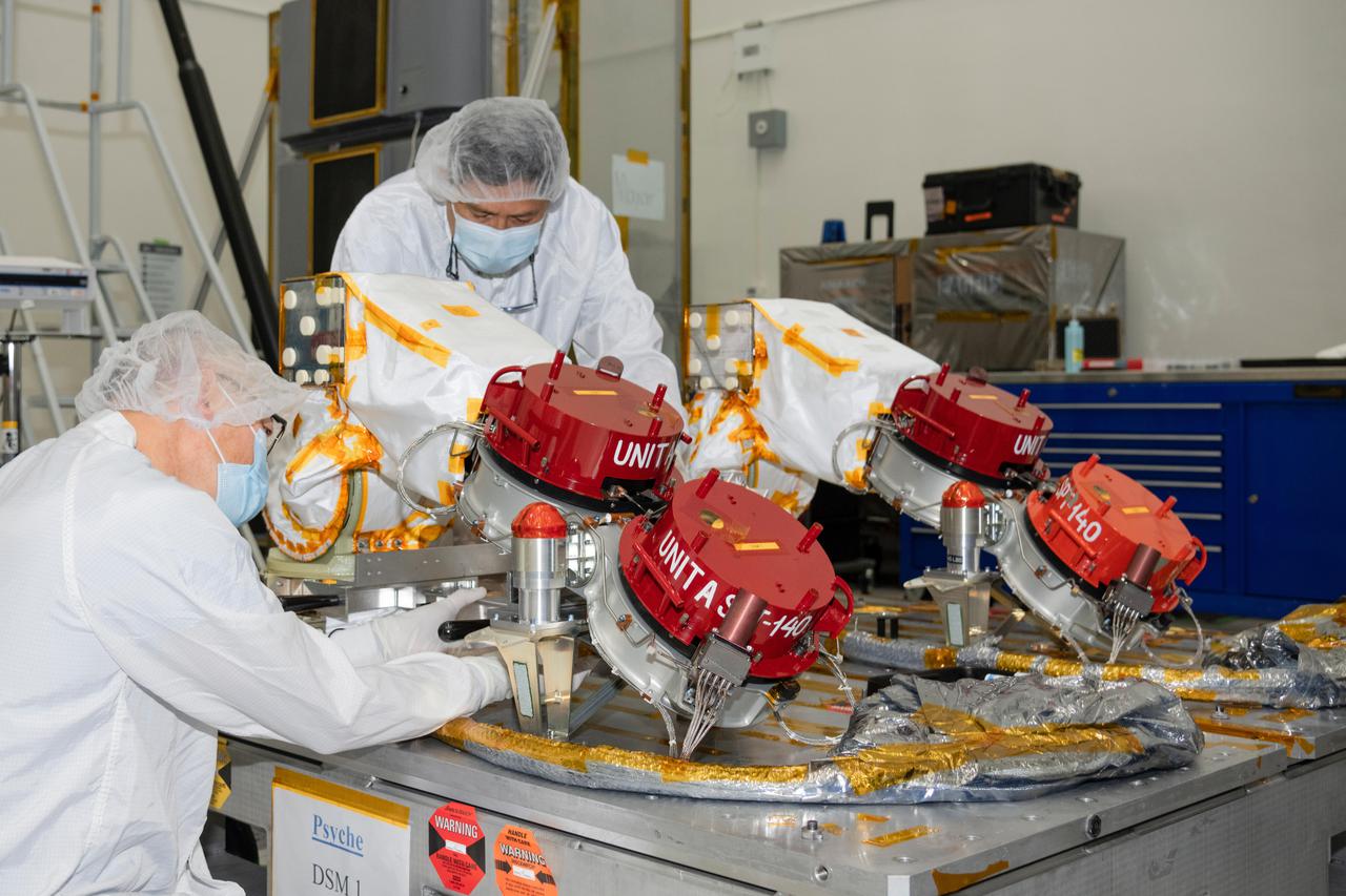
Engineers at NASA's Jet Propulsion Laboratory in Southern California prepare to integrate four Hall thrusters (beneath red protective covers) into the agency's Psyche spacecraft in July 2021. Psyche is set to launch in August 2022 and will travel to its target, a metal-rich asteroid also named Psyche, under the power of solar electric propulsion. This super-efficient mode of propulsion uses solar arrays to capture sunlight that is converted into electricity to power the spacecraft's thrusters. The thrusters work by turning xenon gas, a neutral gas used in car headlights and plasma TVs, into xenon ions. As the xenon ions are accelerated out of the thruster, they create the thrust that will propel the spacecraft. On the Psyche spacecraft, Hall thrusters will be used for the first time beyond lunar orbit, demonstrating that they could play a role in supporting future missions to deep space. https://photojournal.jpl.nasa.gov/catalog/PIA24788

Engineers in a clean room at NASA's Jet Propulsion Laboratory in Southern California build the nadir deck for NASA's Europa Clipper spacecraft. The deck will stabilize the spacecraft's sensors and help the mission team ensure its instruments are oriented correctly. With an internal global ocean under a thick layer of ice, Jupiter's moon Europa may have the potential to harbor existing life. Europa Clipper will swoop around Jupiter on an elliptical path, dipping close to the moon on each flyby. Understanding Europa's habitability will help scientists better understand how life developed on Earth and the potential for finding life beyond our planet. Europa Clipper is set to launch in 2024. https://photojournal.jpl.nasa.gov/catalog/PIA24480
This archival image was released as part of a gallery comparing JPL’s past and present, commemorating the 80th anniversary of NASA’s Jet Propulsion Laboratory on Oct. 31, 2016. Building 264, also known as the Space Flight Support Building, hosts engineers supporting space missions in flight at NASA's Jet Propulsion Laboratory. It used to be just two stories, as seen in this image from January 1972, but then the Viking project to Mars needed more room. The building still serves the same function today, but now has eight floors. http://photojournal.jpl.nasa.gov/catalog/PIA21123
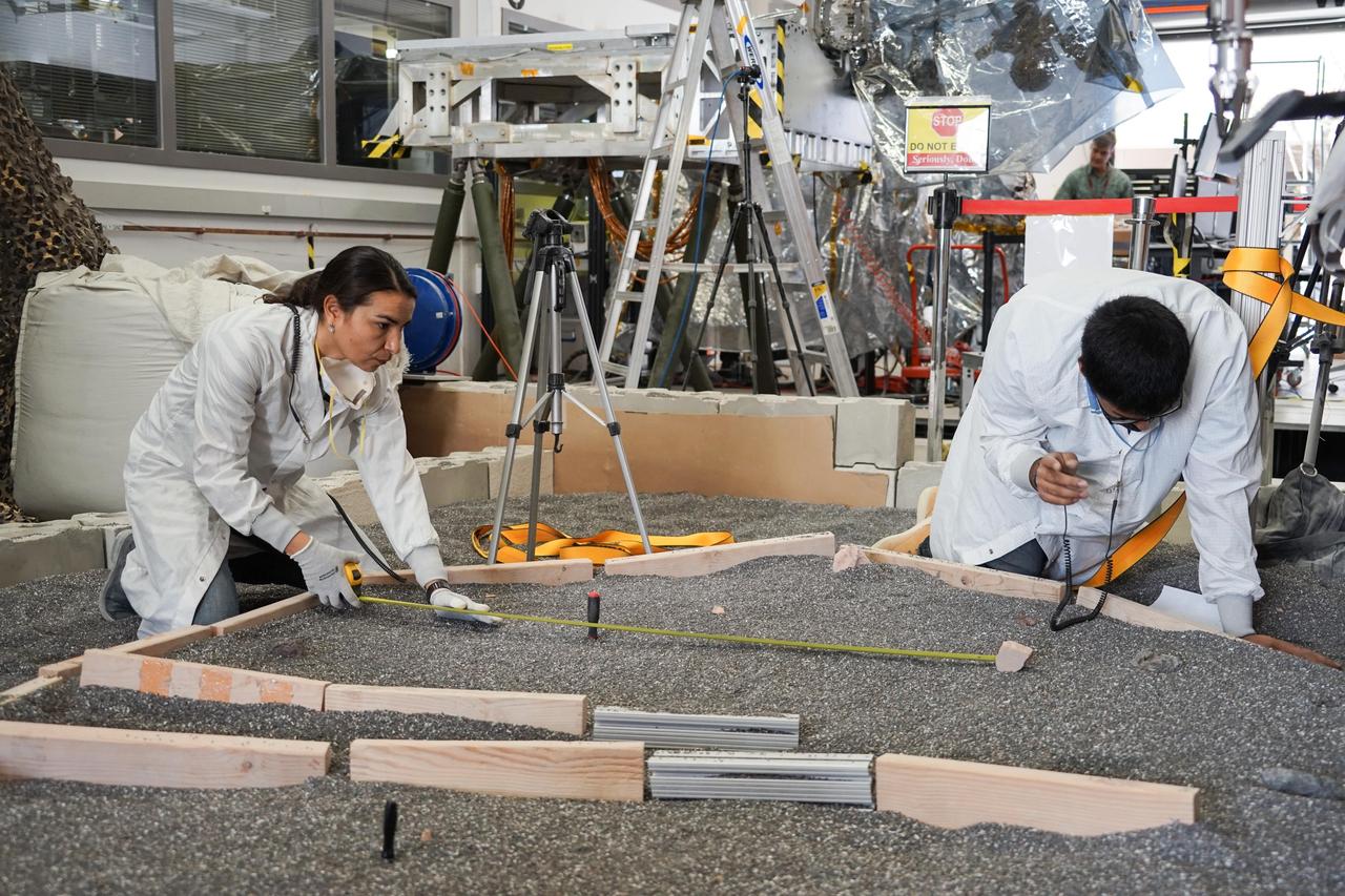
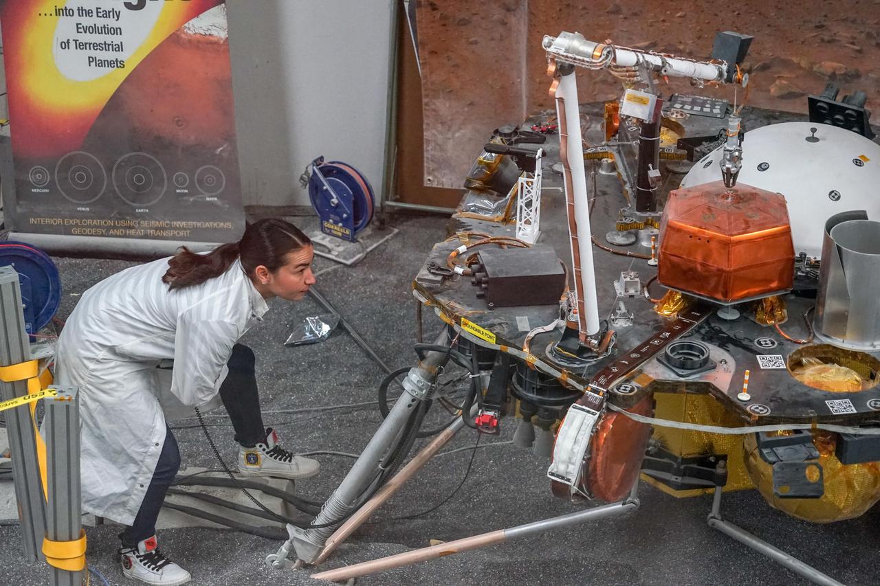
Engineers Marleen Sundgaard (left) and Pranay Mishra measure their test lander's "workspace" -- the terrain where scientists want to set InSight's instruments -- at NASA's Jet Propulsion Laboratory in Pasadena, California. Making sure each feature of the workspace on Mars is mimicked here on Earth allows for more reliable tests to be performed before actually setting down InSight's instruments. https://photojournal.jpl.nasa.gov/catalog/PIA22880
Engineers and technicians at NASA's Jet Propulsion Laboratory in Pasadena, California, integrate the rover motor controller assembly (RMCA) into the Mars 2020 rover's body. The RMCA is the electrical heart of the rover's mobility and motion systems, commanding and regulating the movement of the motors in the rover's wheels, robotic arms, mast, drill and sample-handling functions. The image was taken on April 29, 2019, in the Spacecraft Assembly Facility's High Bay 1 clean room at JPL. https://photojournal.jpl.nasa.gov/catalog/PIA23194

Some of the dozens of engineers involved in creating a ventilator prototype specially targeted to coronavirus disease patients at NASA's Jet Propulsion Laboratory in Southern California. Called VITAL (Ventilator Intervention Technology Accessible Locally), the prototype was created in 37 days in March and April 2020. Left to right, standing: Shaunessy Grant, Michael Johnson, Dave Van Buren, Michelle Easter. Left to right, kneeling: Brandon Metz, Patrick Degrosse. https://photojournal.jpl.nasa.gov/catalog/PIA23891
Pictured is a component of the Rocket Based Combined Cycle (RBCC) engine. This engine was designed to ultimately serve as the near term basis for Two Stage to Orbit (TSTO) air breathing propulsion systems and ultimately a Single Stage to Orbit (SSTO) air breathing propulsion system.
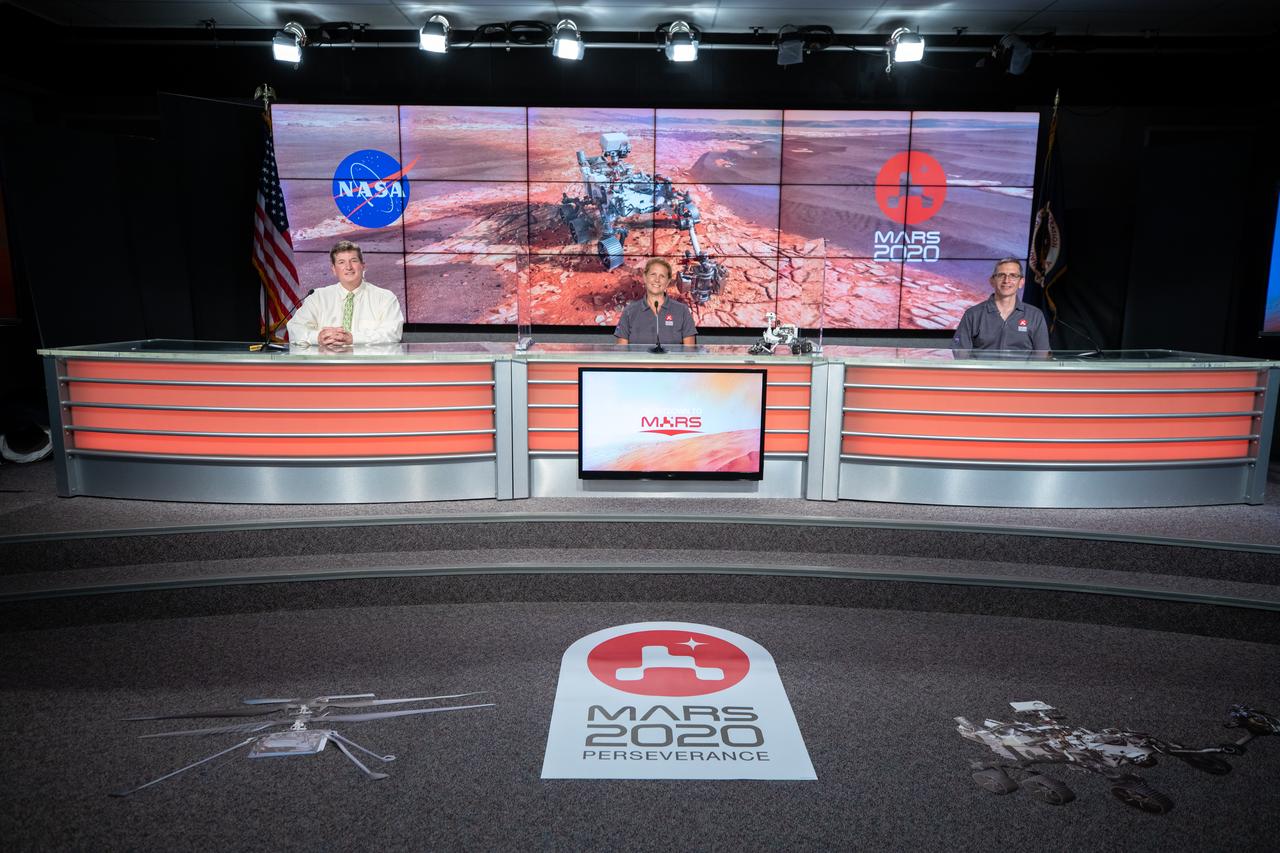
A Mars 2020 Mission Engineering and Science Briefing is held at NASA’s Kennedy Space Center in Florida on July 27, 2020. Participating in the briefing from left, are Moderator DC Agle, NASA’s Jet Propulsion Laboratory; Lori Glaze, Planetary Science Division director, NASA Headquarters; and Ken Farley, project scientist, California Institute of Technology. The Mars Perseverance rover is scheduled to launch July 30, on a United Launch Alliance Atlas V 541 rocket from Space Launch Complex 41 at nearby Cape Canaveral Air Force Station. The rover is part of NASA’s Mars Exploration Program, a long-term effort of robotic exploration of the Red Planet. The rover will search for habitable conditions in the ancient past and signs of past microbial life on Mars. The Launch Services Program at Kennedy is responsible for launch management.
A Mars 2020 Mission Engineering and Science Briefing is held at NASA’s Kennedy Space Center in Florida on July 27, 2020. Participating in the briefing from left, are Moderator DC Agle, NASA’s Jet Propulsion Laboratory; Lori Glaze, Planetary Science Division director, NASA Headquarters; and Ken Farley, project scientist, California Institute of Technology. The Mars Perseverance rover is scheduled to launch July 30, on a United Launch Alliance Atlas V 541 rocket from Space Launch Complex 41 at nearby Cape Canaveral Air Force Station. The rover is part of NASA’s Mars Exploration Program, a long-term effort of robotic exploration of the Red Planet. The rover will search for habitable conditions in the ancient past and signs of past microbial life on Mars. The Launch Services Program at Kennedy is responsible for launch management.
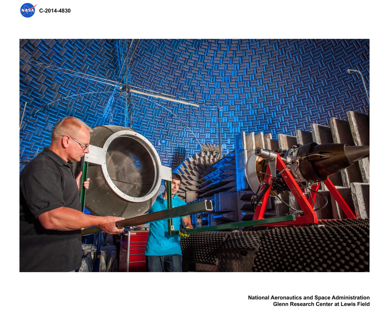
Truck Mounted Turbofan Engine in Aero Acoustic Propulsion Laboratory, AAPL, Facility
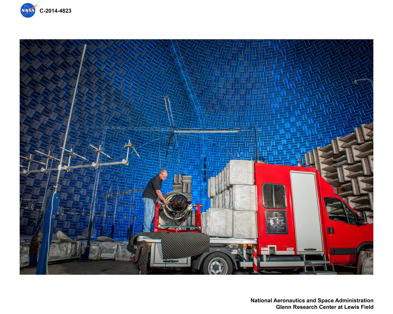
Truck Mounted Turbofan Engine in Aero Acoustic Propulsion Laboratory, AAPL, Facility