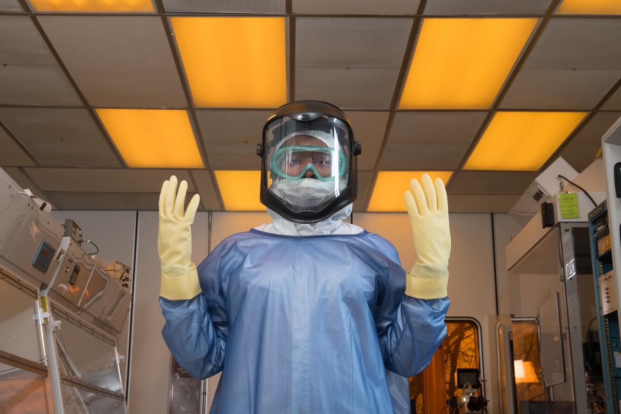
Laboratory researcher suits up for work in a research clean room. Personal Protective Equipment, PPE, Portait Series
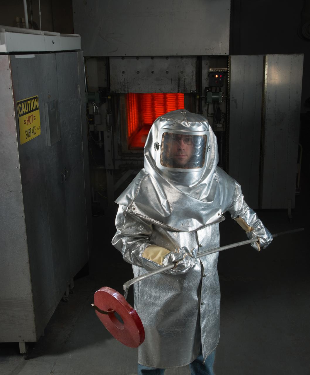
Personal Protective Equipment, PPE, Portrait Series, Welch_503059, Shape memory alloys, Shape memory alloy, Welch-Bey-503059, Glen Bigelow,
NASA Wide-field Infrared Survey Explorer spacecraft sits with its protective covering.
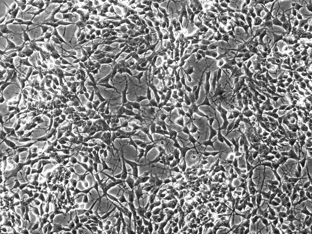
jsc2022e031232 (4/26/2022) --- A preflight view of differentiating neuron-like cell cultures with a dense network of neurites for intercellular interaction. The PROtection MEdiated by antioxidant nanoTEchnOlogy against neuronal damage in space (PROMETEO) (Antioxidant Protection) investigation proposes the use of biocompatible and biodegradable polydopamine-based nanoparticles to provide antioxidant protection to neurons undergoing exposure to altered gravity and cosmic radiation. Image courtesy of Istituto Italiano di Tecnologia.

CAPE CANAVERAL, Fla. – A view of the interior of one of four new emergency egress vehicles, called Mine-Resistant Ambush-Protected, or MRAP, vehicles is shown. The MRAPs are at the Maintenance and Operations Facility at NASA’s Kennedy Space Center in Florida. The MRAPs arrived from the U.S. Army Red River Depot in Texarkana, Texas in December 2013. The vehicles were processed in and then transported to the Rotation, Processing and Surge Facility near the Vehicle Assembly Building for temporary storage. The Ground Systems Development and Operations Program at Kennedy led the efforts to an emergency egress vehicle that future astronauts could quickly use to leave the Launch Complex 39 area in case of an emergency. During crewed launches of NASA’s Space Launch System and Orion spacecraft, the MRAP will be stationed by the slidewire termination area at the pad. In case of an emergency, the crew will ride a slidewire to the ground and immediately board the MRAP for safe egress from the pad. The new vehicles replace the M-113 vehicles that were used during the Space Shuttle Program. Photo credit: NASA/Kim Shiflett
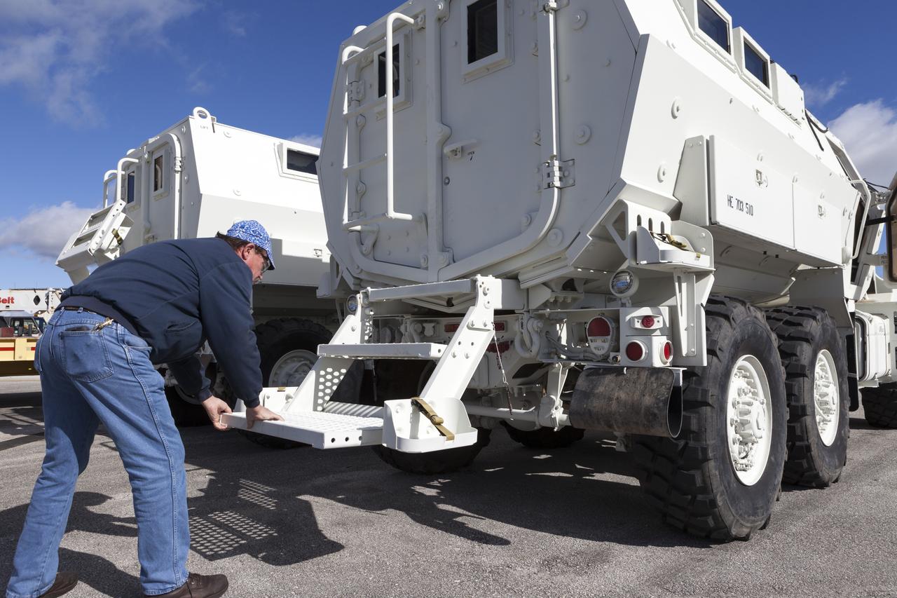
CAPE CANAVERAL, Fla. – A URS Federal Services worker pulls down the steps to the entrance of one of the four new emergency egress vehicles, called Mine-Resistant Ambush-Protected, or MRAP, vehicles at the Maintenance and Operations Facility at NASA’s Kennedy Space Center in Florida. The MRAPs arrived from the U.S. Army Red River Depot in Texarkana, Texas in December 2013. The vehicles were processed in and then transported to the Rotation, Processing and Surge Facility near the Vehicle Assembly Building for temporary storage. The Ground Systems Development and Operations Program at Kennedy led the efforts to an emergency egress vehicle that future astronauts could quickly use to leave the Launch Complex 39 area in case of an emergency. During crewed launches of NASA’s Space Launch System and Orion spacecraft, the MRAP will be stationed by the slidewire termination area at the pad. In case of an emergency, the crew will ride a slidewire to the ground and immediately board the MRAP for safe egress from the pad. The new vehicles replace the M-113 vehicles that were used during the Space Shuttle Program. Photo credit: NASA/Kim Shiflett
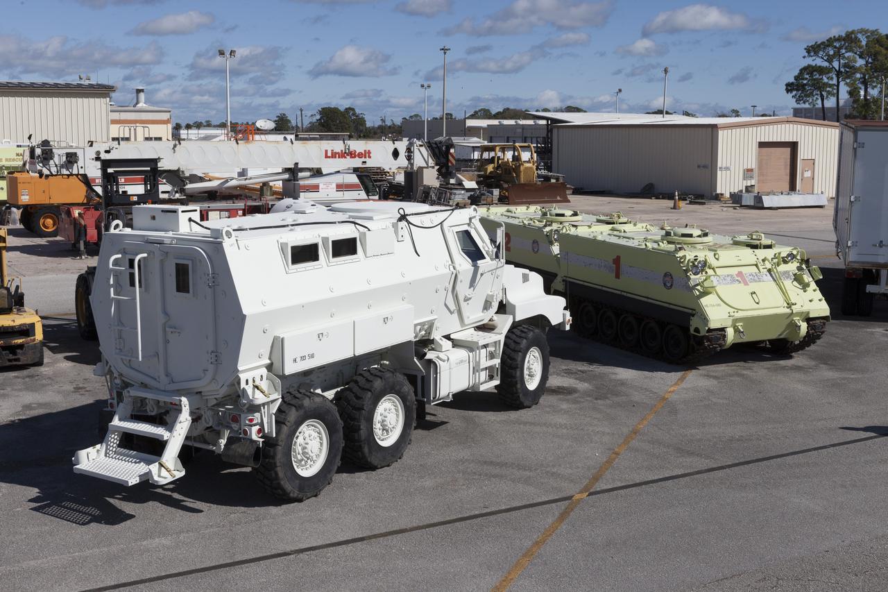
CAPE CANAVERAL, Fla. – One of four new emergency egress vehicles, called Mine-Resistant Ambush-Protection, or MRAP, vehicles sits near space shuttle-era M-113 vehicles at the Maintenance and Operations Facility at NASA’s Kennedy Space Center in Florida. The MRAPs arrived from the U.S. Army Red River Depot in Texarkana, Texas in December 2013. The vehicles were processed in and then transported to the Rotation, Processing and Surge Facility near the Vehicle Assembly Building for temporary storage. The Ground Systems Development and Operations Program at Kennedy led the efforts to an emergency egress vehicle that future astronauts could quickly use to leave the Launch Complex 39 area in case of an emergency. During crewed launches of NASA’s Space Launch System and Orion spacecraft, the MRAP will be stationed by the slidewire termination area at the pad. In case of an emergency, the crew will ride a slidewire to the ground and immediately board the MRAP for safe egress from the pad. The new vehicles replace the M-113 vehicles that were used during the Space Shuttle Program. Photo credit: NASA/Kim Shiflett

CAPE CANAVERAL, Fla. – One of four new emergency egress vehicles, called Mine-Resistant Ambush-Protection, or MRAP, vehicles is driven to the Maintenance and Operations Facility at Kennedy Space Center in Florida. The MRAPs arrived from the U.S. Army Red River Depot in Texarkana, Texas in December 2013. The vehicles were processed in and then transported to the Rotation, Processing and Surge Facility near the Vehicle Assembly Building for temporary storage. The Ground Systems Development and Operations Program at Kennedy led the efforts to an emergency egress vehicle that future astronauts could quickly use to leave the Launch Complex 39 area in case of an emergency. During crewed launches of NASA’s Space Launch System and Orion spacecraft, the MRAP will be stationed by the slidewire termination area at the pad. In case of an emergency, the crew will ride a slidewire to the ground and immediately board the MRAP for safe egress from the pad. The new vehicles replace the M-113 vehicles that were used during the Space Shuttle Program. Photo credit: NASA/Kim Shiflett
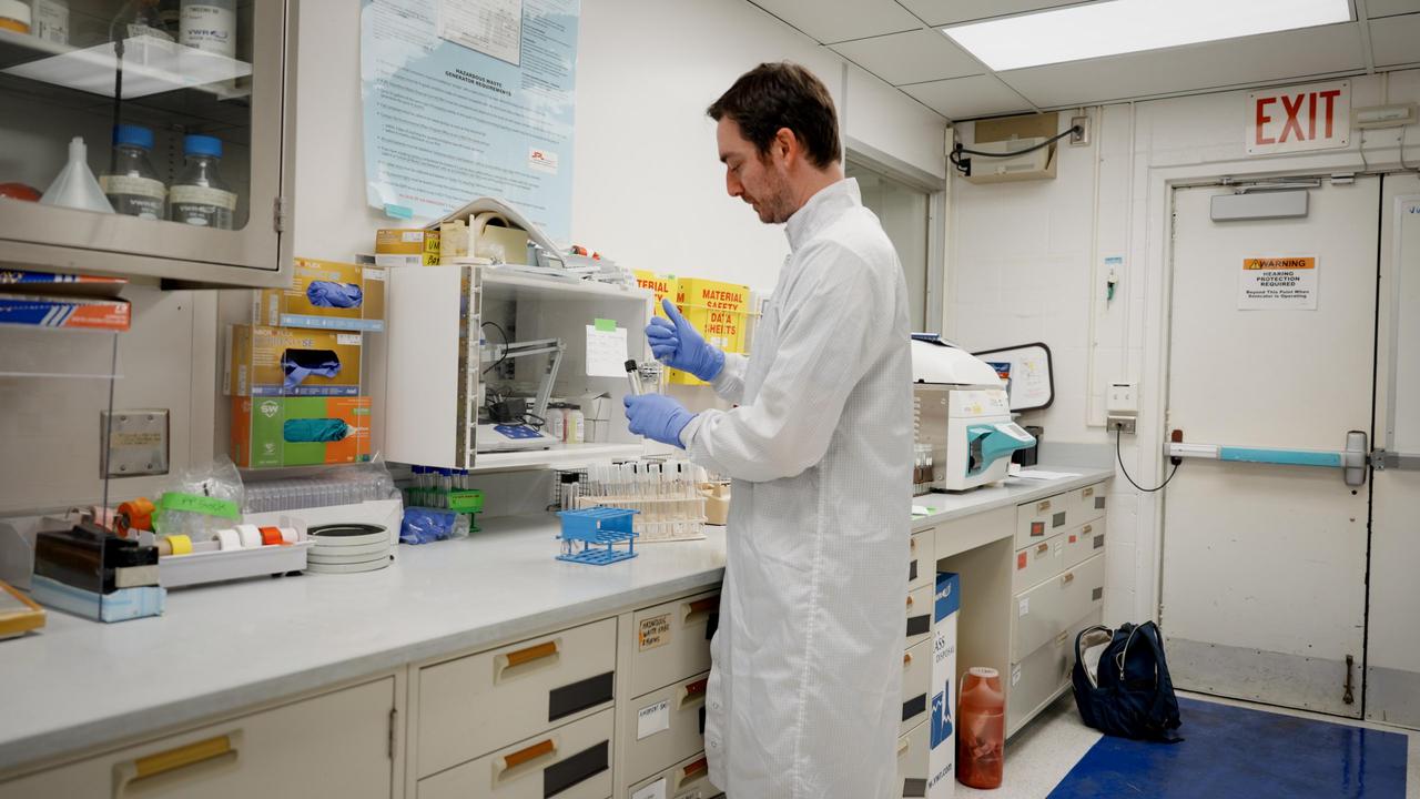
A planetary protection engineer at NASA's Jet Propulsion Laboratory prepares samples for analysis on March 20, 2024. The samples, swabbed from the surfaces of the agency's Europa Clipper spacecraft during its construction, were collected to help monitor the mission's adherence to strict standards for biological cleanliness. Created in keeping with the international 1967 Outer Space Treaty, the mission's planetary protection protocols are designed to minimize the chance that microbes brought from Earth could compromise future scientific investigations at its target destination: Jupiter's icy moon Europa. Europa Clipper's three main science objectives are to determine the thickness of the moon's icy shell and its interactions with the ocean below, to investigate its composition, and to characterize its geology. The mission's detailed exploration of Europa will help scientists better understand the astrobiological potential for habitable worlds beyond our planet. https://photojournal.jpl.nasa.gov/catalog/PIA26441
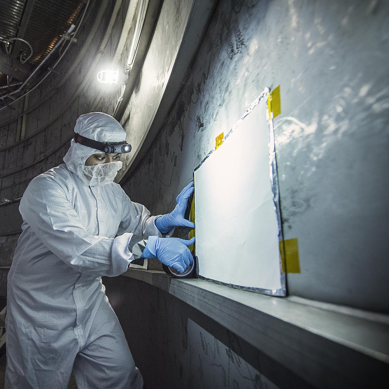
Contamination from organic molecules can harm delicate instruments and engineers are taking special care at NASA to prevent that from affecting the James Webb Space Telescope (and all satellites and instruments). Recently, Nithin Abraham, a Thermal Coatings Engineer placed Molecular Adsorber Coating or "MAC" panels in the giant chamber where the Webb telescope will be tested. This contamination can occur through a process when a vapor or odor is emitted by a substance. This is called "outgassing." The "new car smell" is an example of that, and is unhealthy for people and sensitive satellite instruments. So, NASA engineers have created a new way to protect those instruments from the damaging effects of contamination coming from outgassing. "The Molecular Adsorber Coating (MAC) is a NASA Goddard coatings technology that was developed to adsorb or entrap outgassed molecular contaminants for spaceflight applications," said Nithin Abraham, Thermal Coatings Engineer at NASA's Goddard Space Flight Center in Greenbelt, Maryland. MAC is currently serving as an innovative contamination mitigation tool for Chamber A operations at NASA Johnson Space Center in Houston, Texas. MAC can be used to keep outgassing from coming in from outside areas or to capture outgassing directly from hardware, components, and within instrument cavities. In this case, MAC is helping by capturing outgassed contaminants outside the test chamber from affecting the Webb components. MAC is expected to capture the outgassed contaminants that exist in the space of the vacuum chamber (not from the Webb components). Credit: NASA/GoddardChris Gunn Read more: <a href="http://www.nasa.gov/feature/goddard/nasa-technology-protects-webb-telescope-from-contamination" rel="nofollow">www.nasa.gov/feature/goddard/nasa-technology-protects-web...</a> <b><a href="http://www.nasa.gov/audience/formedia/features/MP_Photo_Guidelines.html" rel="nofollow">NASA image use policy.</a></b> <b><a href="http://www.nasa.gov/centers/goddard/home/index.html" rel="nofollow">NASA Goddard Space Flight Center</a></b> enables NASA’s mission through four scientific endeavors: Earth Science, Heliophysics, Solar System Exploration, and Astrophysics. Goddard plays a leading role in NASA’s accomplishments by contributing compelling scientific knowledge to advance the Agency’s mission. <b>Follow us on <a href="http://twitter.com/NASAGoddardPix" rel="nofollow">Twitter</a></b> <b>Like us on <a href="http://www.facebook.com/pages/Greenbelt-MD/NASA-Goddard/395013845897?ref=tsd" rel="nofollow">Facebook</a></b> <b>Find us on <a href="http://instagrid.me/nasagoddard/?vm=grid" rel="nofollow">Instagram</a></b>
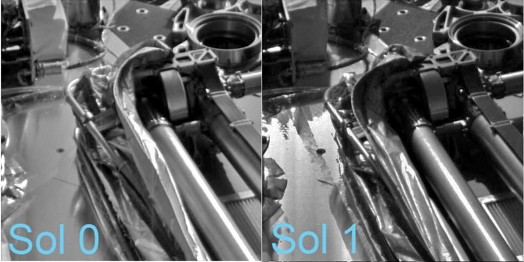
Relatively warmer daytime temperatures on Mars have allowed the biobarrier -- a shiny, protective film -- to peel away a little more from the robotic arm of NASA Phoenix Mars Lander.
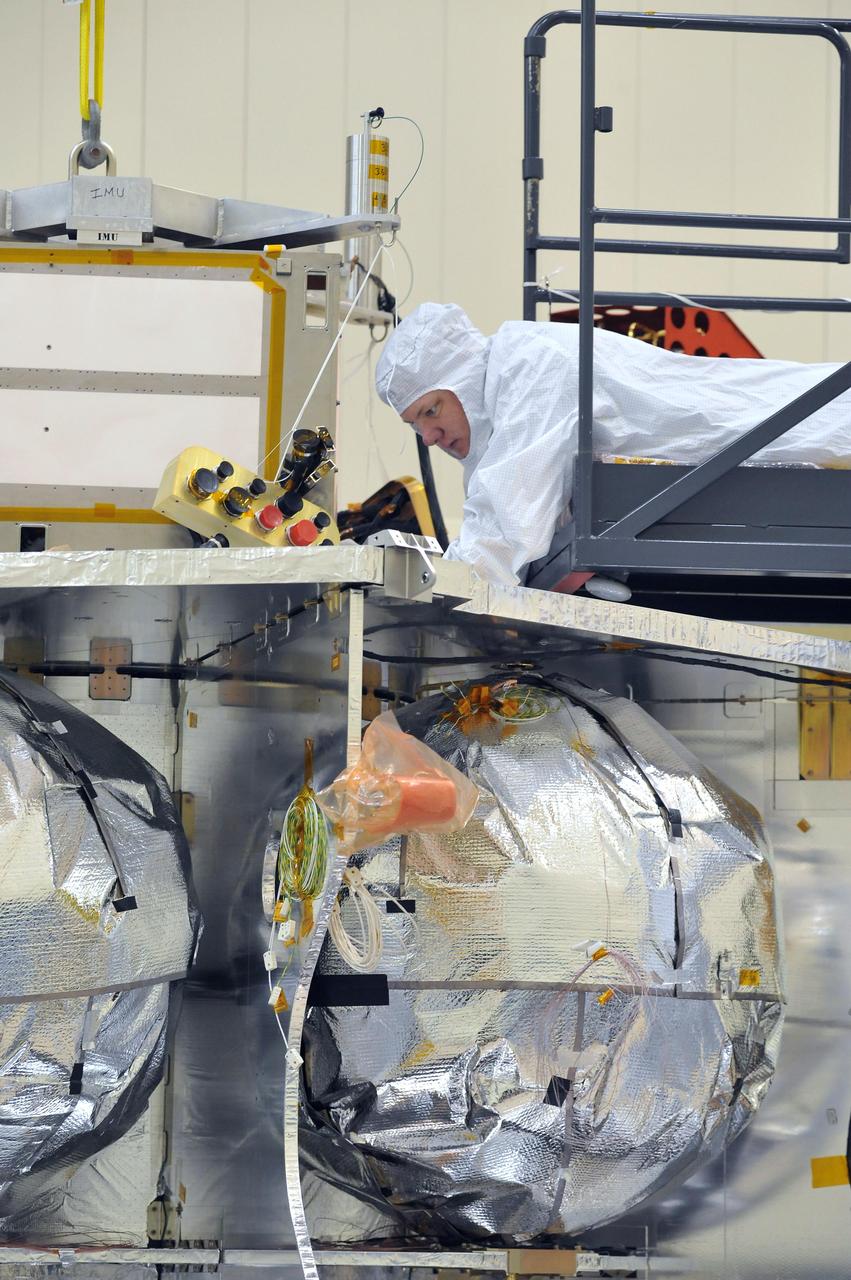
Technicians installed the special radiation vault for NASA Juno spacecraft on the propulsion module. The radiation vault has titanium walls to protect the spacecraft electronic brain and heart from Jupiter harsh radiation environment.

"Self Protection for Women,"sponsored by the Federal Women's Program Committee and the Training Office, will be held June 10 in the Activities Center. This presentation contains practical self-defense techniques that can be learned in ONE hour. Lt. Jim Bullard of the Memphis Police Department, the originator of the program, considers it as pertinent to men as it is to women. Bullard's emphasis is proper "attitude," without which self defense techniques are meaningless. Published in Langley Researcher, May 20,1983 page 2. Mary Jackson, Manager of the Federal Women's Program Committee participating in demonstration.

"Self Protection for Women,"sponsored by the Federal Women's Program Committee and the Training Office, will be held June 10 in the Activities Center. This presentation contains practical self-defense techniques that can be learned in ONE hour. Lt. Jim Bullard of the Memphis Police Department, the originator of the program, considers it as pertinent to men as it is to women. Bullard's emphasis is proper "attitude," without which self defense techniques are meaningless. Published in Langley Researcher, May 20,1983 page 2. Mary Jackson, Manager of the Federal Women's Program Committee participating in demonstration.
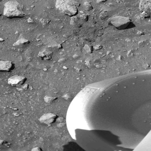
The patch of dark material toward the top of this picture (arrow) taken by NASA's Viking 1 Lander is the debris kicked up by the impact of a protective cover ejected from the spacecraft at 1 a.m. today. The cylindrical cover, which bounced out of view of the camera, protects the scoop at the end of the soil sampler arm. (The scoop will dig into the Martian surface for the first time on July 28). Dust and debris atop the footpad remains as it was seen in the Lander's first picture taken immediately after landing two days ago. No wind modification is apparent. On the surface, a variety of block sizes, shapes and tones are seen, and some rocks are Partially buried. http://photojournal.jpl.nasa.gov/catalog/PIA00384

NASA astronauts Christina Koch and Victor J. Glover examine a sample of AVCOAT Thermal Protection System (TPS) that protects the Orion spacecraft as it enters Earth’s atmosphere.
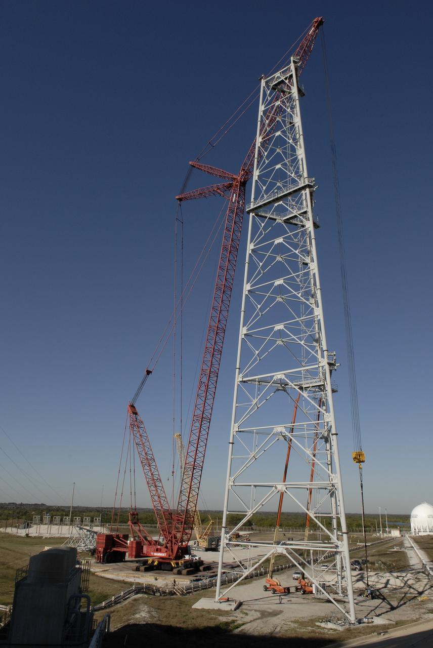
CAPE CANAVERAL, Fla. – A giant crane is used to add additional segments to the new lightning towers on Launch Pad 39B at NASA's Kennedy Space Center in Florida. Three new lightning towers on the pad will be 500 feet tall with an additional 100-foot fiberglass mast atop supporting a wire catenary system. Pad 39B will be the site of the first Ares vehicle launch, including the Ares I-X test flight that is targeted for July 2009. This improved lightning protection system allows for the taller height of the Ares I rocket compared to the space shuttle. Photo credit: NASA/Kim Shiflett

CAPE CANAVERAL, Fla. – Progress is being made on construction of the new lightning towers on Launch Pad 39B at NASA's Kennedy Space Center in Florida. New sections are being added with the help of a giant crane. Three new lightning towers on the pad will be 500 feet tall with an additional 100-foot fiberglass mast atop supporting a wire catenary system. Pad 39B will be the site of the first Ares vehicle launch, including the Ares I-X test flight that is targeted for July 2009. This improved lightning protection system allows for the taller height of the Ares I rocket compared to the space shuttle. Photo credit: NASA/Kim Shiflett

CAPE CANAVERAL, Fla. – Brilliant beams of sunlight bounce off the new lightning tower under construction on Launch Pad 39B at NASA's Kennedy Space Center in Florida. New sections are being added with the help of a giant crane (at right). Three new lightning towers on the pad will be 500 feet tall with an additional 100-foot fiberglass mast atop supporting a wire catenary system. Pad 39B will be the site of the first Ares vehicle launch, including the Ares I-X test flight that is targeted for July 2009. This improved lightning protection system allows for the taller height of the Ares I rocket compared to the space shuttle. Photo credit: NASA/Kim Shiflett
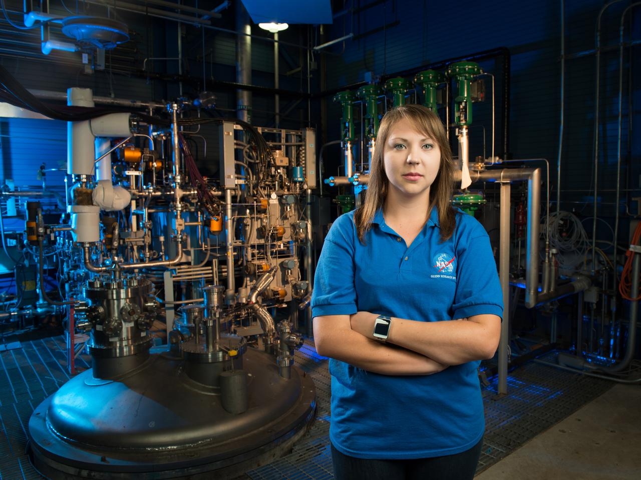
NASA Glenn engineer Monica Guzik in the Small Multi-Purpose Research Facility (SMiRF). The facility provides the ability to simulate the environmental conditions encountered in space for a variety of cryogenic applications such as thermal protection systems, fluid transfer operations and propellant level gauging. SMiRF is a low-cost, small-scale screening facility for concept and component testing of a wide variety of hardware and is capable of testing cryogenic hydrogen, oxygen, methane and nitrogen.
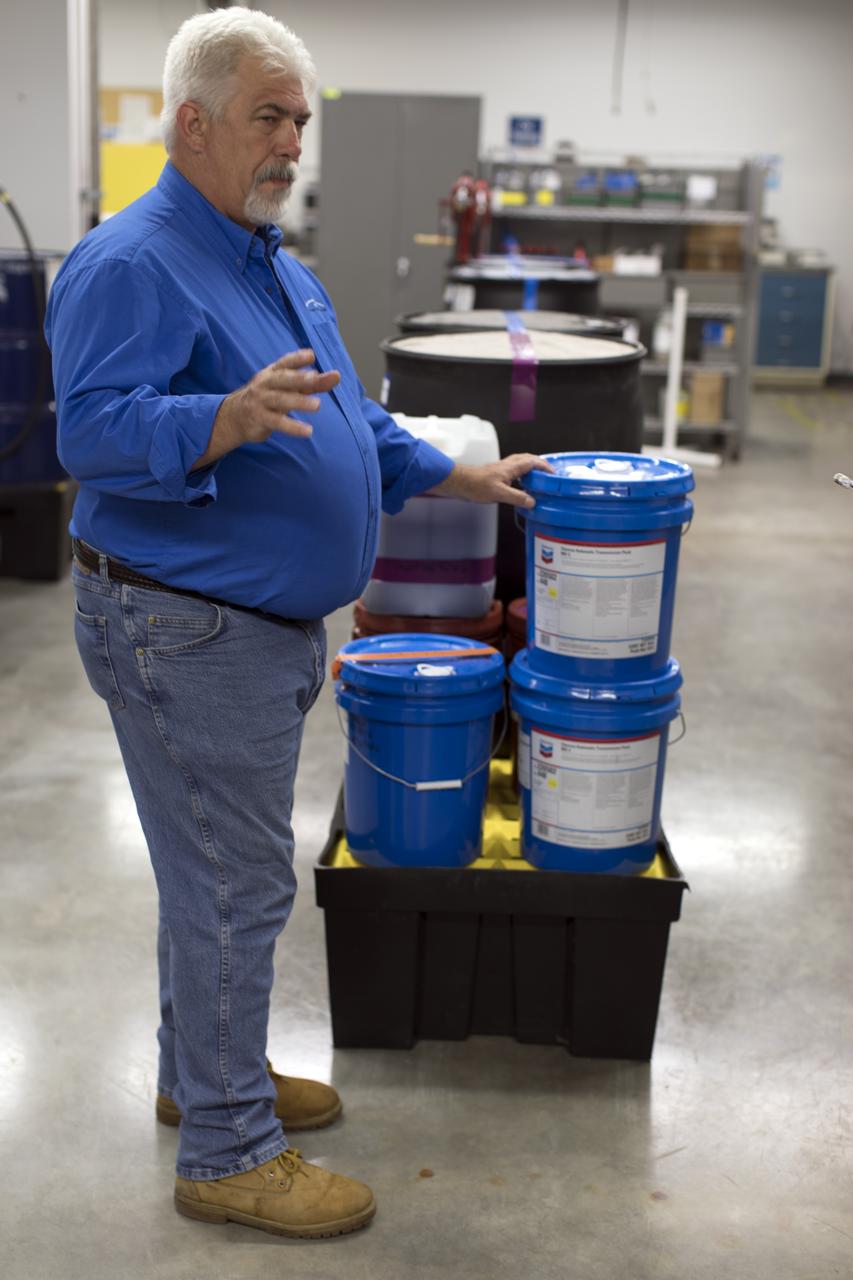
Tim King of Jacobs at NASA's Kennedy Space Center in Florida, explains operations in the Oil Pharmacy operated under the Test and Operations Support Contract, or TOSC. The facility consolidated storage and distribution of petroleum products used in equipment maintained under the contract. This included standardized naming, testing processes and provided a central location for distribution of oils used in everything from simple machinery to the crawler-transporter and cranes in the Vehicle Assembly Building.
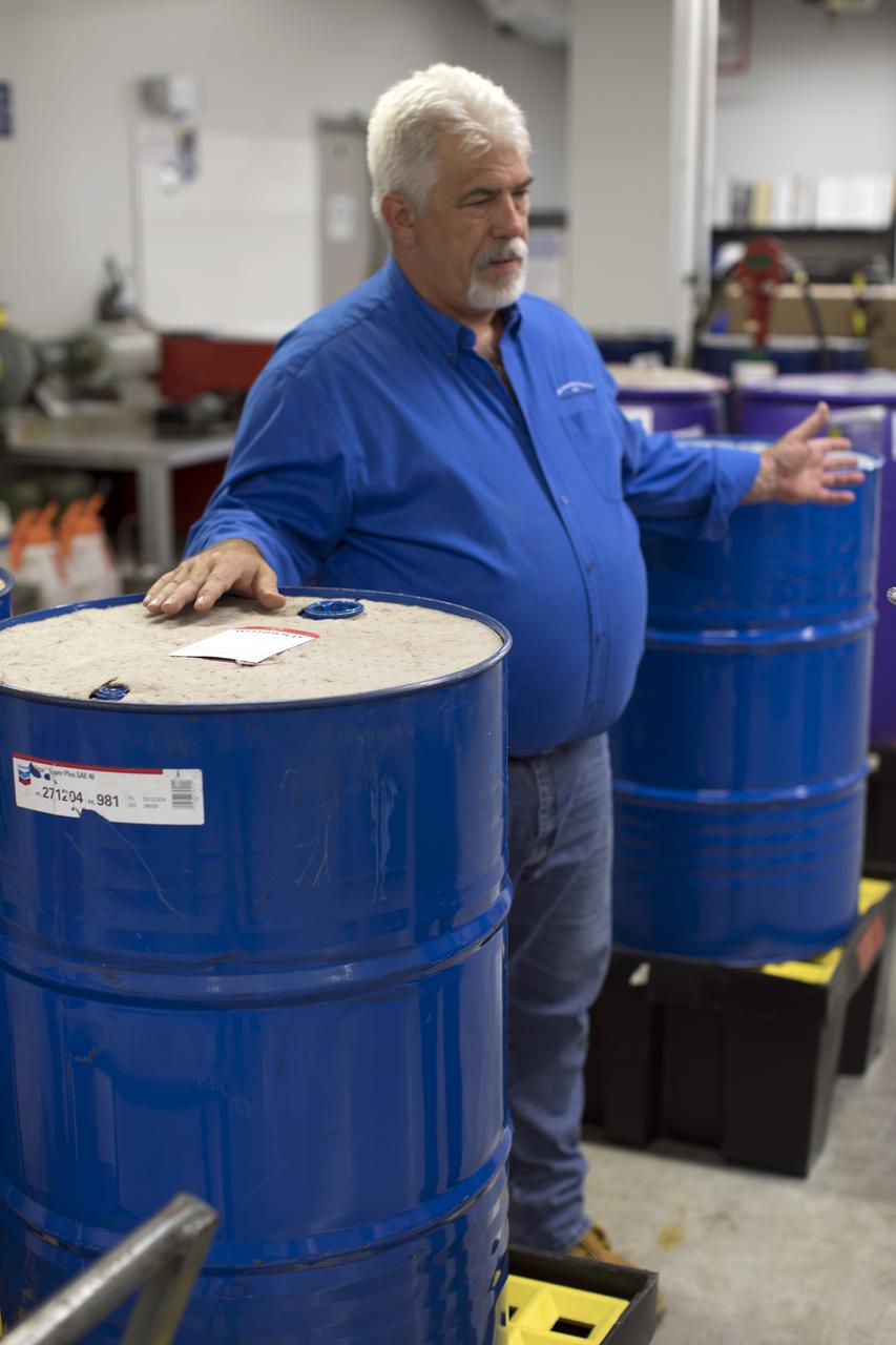
Tim King of Jacobs at NASA's Kennedy Space Center in Florida, explains operations in the Oil Pharmacy operated under the Test and Operations Support Contract, or TOSC. The facility consolidated storage and distribution of petroleum products used in equipment maintained under the contract. This included standardized naming, testing processes and provided a central location for distribution of oils used in everything from simple machinery to the crawler-transporter and cranes in the Vehicle Assembly Building.
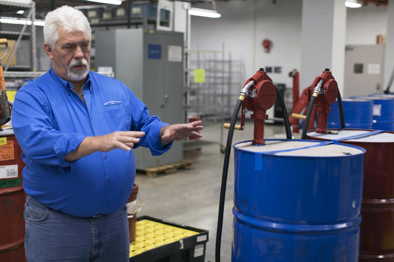
Tim King of Jacobs at NASA's Kennedy Space Center in Florida, explains operations in the Oil Pharmacy operated under the Test and Operations Support Contract, or TOSC. The facility consolidated storage and distribution of petroleum products used in equipment maintained under the contract. This included standardized naming, testing processes and provided a central location for distribution of oils used in everything from simple machinery to the crawler-transporter and cranes in the Vehicle Assembly Building.
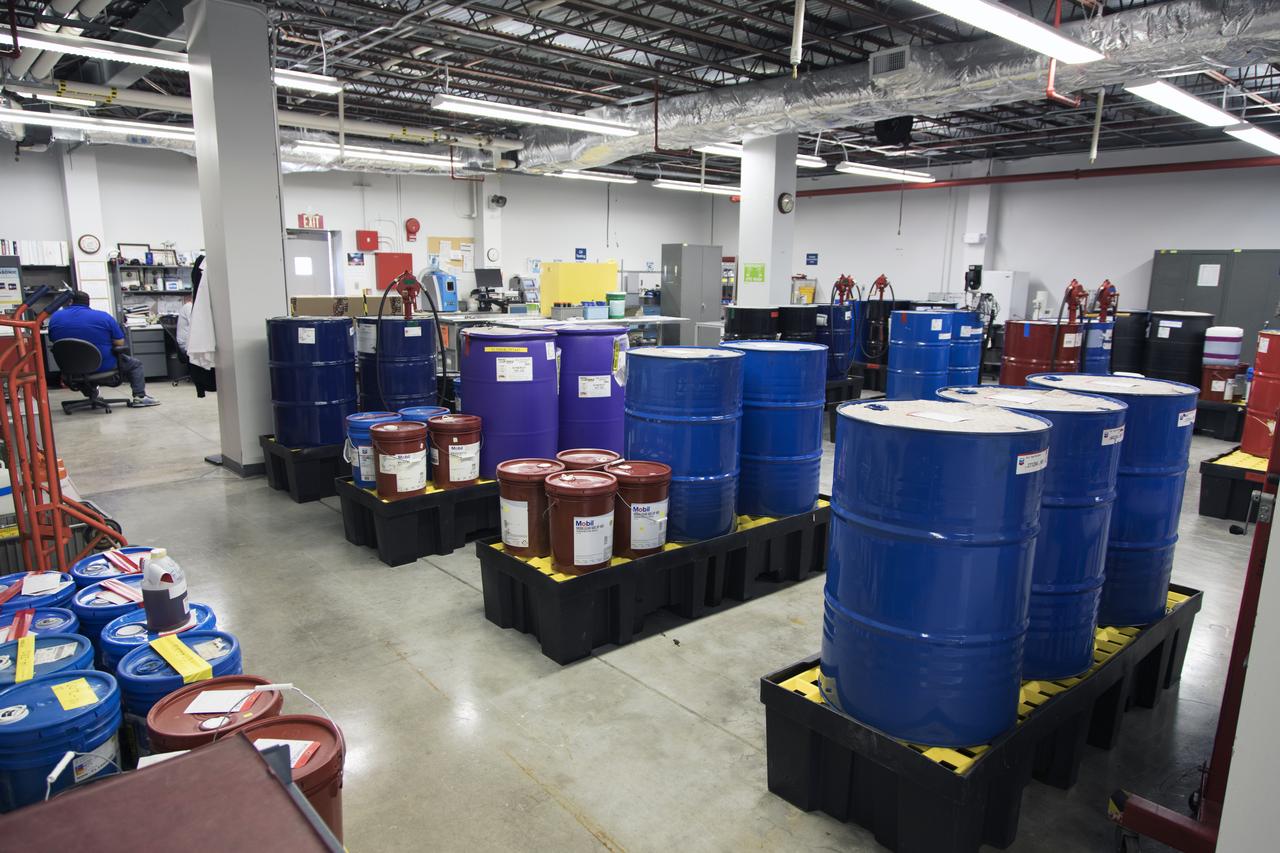
An overall view of the Oil Pharmacy operated under the Test and Operations Support Contract, or TOSC. The facility consolidated storage and distribution of petroleum products used in equipment maintained under the contract. This included standardized naming, testing processes and provided a central location for distribution of oils used in everything from simple machinery to the crawler-transporter and cranes in the Vehicle Assembly Building.
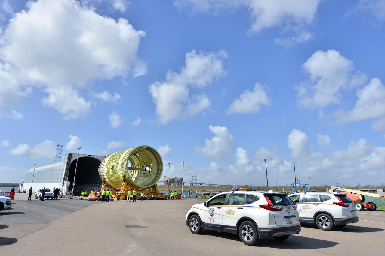
Michoud Protective Services escorts Intertank STA to Pegasus.

Official portrait of Sean Sanders, special agent, NASA Protective Services Office at the agency's Kennedy Space Center in Florida.
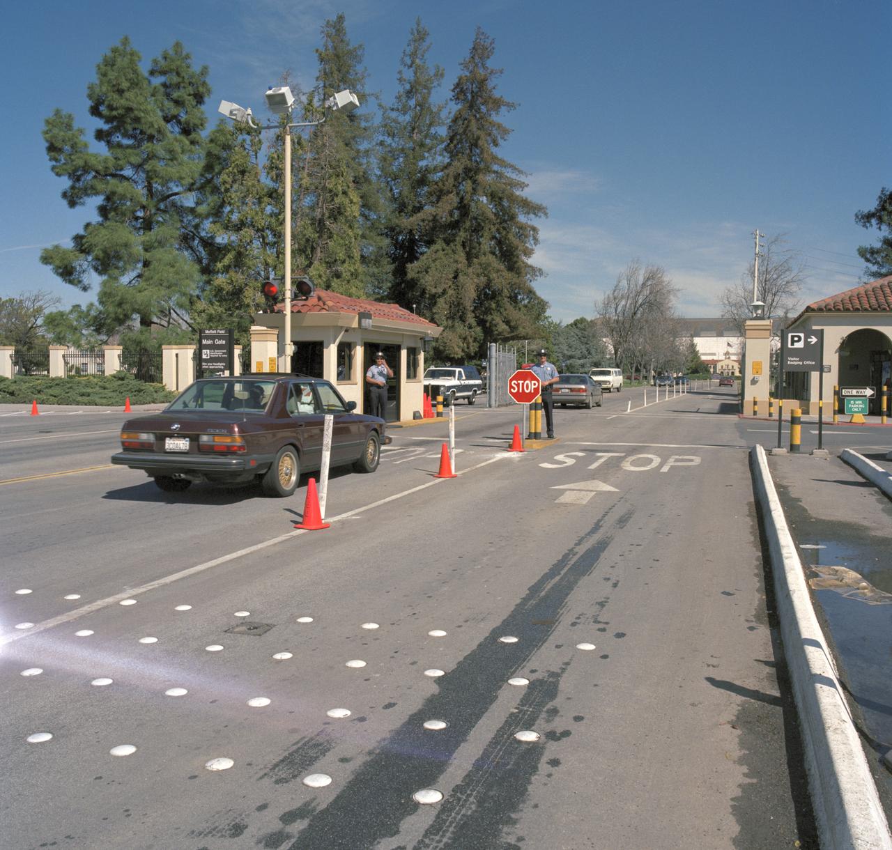
Protective Services Office (Code JP) Personnel On Duty. Main Gate Guards Rubin Cablgas and Robert Burja
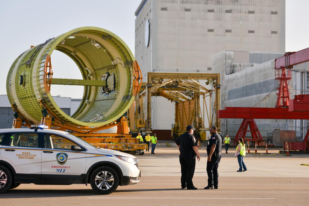
Intertank STA en route to Pegasus, while the Michoud Protective Services guides the route.
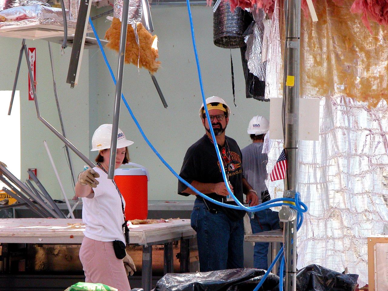
KENNEDY SPACE CENTER, FLA. - KSC employees clean up inside the second floor of the Thermal Protection System Facility damaged by Hurricane Frances. The storm's path over Florida took it through Cape Canaveral and KSC property during Labor Day weekend. Located in Launch Complex 39, the facility is used to manufacture both internal and external insulation products for the Space Shuttle orbiters.
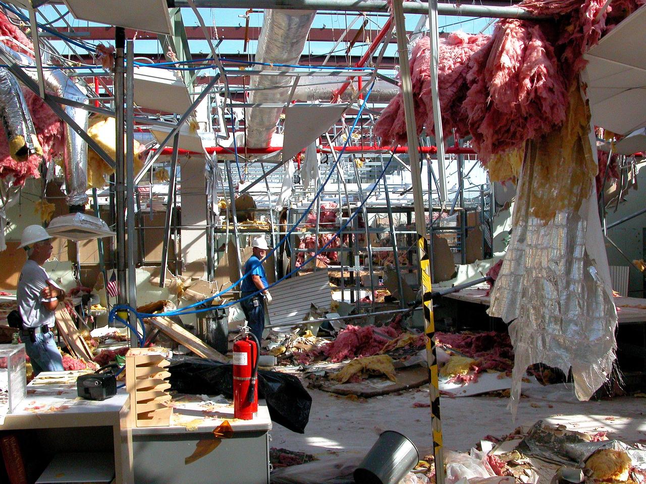
KENNEDY SPACE CENTER, FLA. - KSC employees clean up inside the second floor of the Thermal Protection System Facility damaged by Hurricane Frances. The storm's path over Florida took it through Cape Canaveral and KSC property during Labor Day weekend. Located in Launch Complex 39, the facility is used to manufacture both internal and external insulation products for the Space Shuttle orbiters.
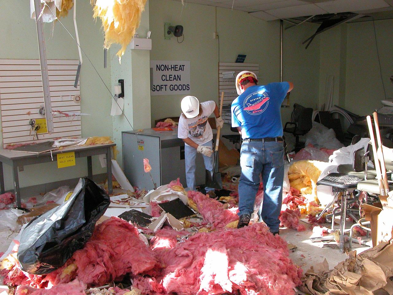
KENNEDY SPACE CENTER, FLA. - KSC employees clean up inside the second floor of the Thermal Protection System Facility damaged by Hurricane Frances. The storm's path over Florida took it through Cape Canaveral and KSC property during Labor Day weekend. Located in Launch Complex 39, the facility is used to manufacture both internal and external insulation products for the Space Shuttle orbiters.
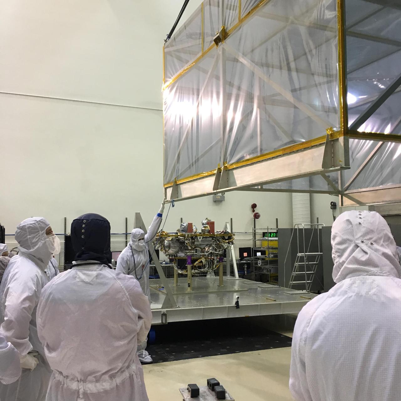
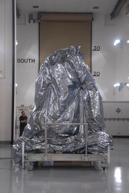
Members of the InSight mission's assembly, test and launch operations (ATLO) team remove the "birdcage" from NASA's InSight spacecraft, in this photo taken June 19, 2017, in a Lockheed Martin clean room facility in Littleton, Colorado. The birdcage is the inner layer of protective housing that shielded the spacecraft while in storage following a postponement of launch. It is made of a film that dissipates electrostatic conditions to protect the spacecraft from contamination. The InSight mission (for Interior Exploration using Seismic Investigations, Geodesy and Heat Transport) is scheduled to launch in May 2018 and land on Mars Nov. 26, 2018. It will investigate processes that formed and shaped Mars and will help scientists better understand the evolution of our inner solar system's rocky planets, including Earth. https://photojournal.jpl.nasa.gov/catalog/PIA21843
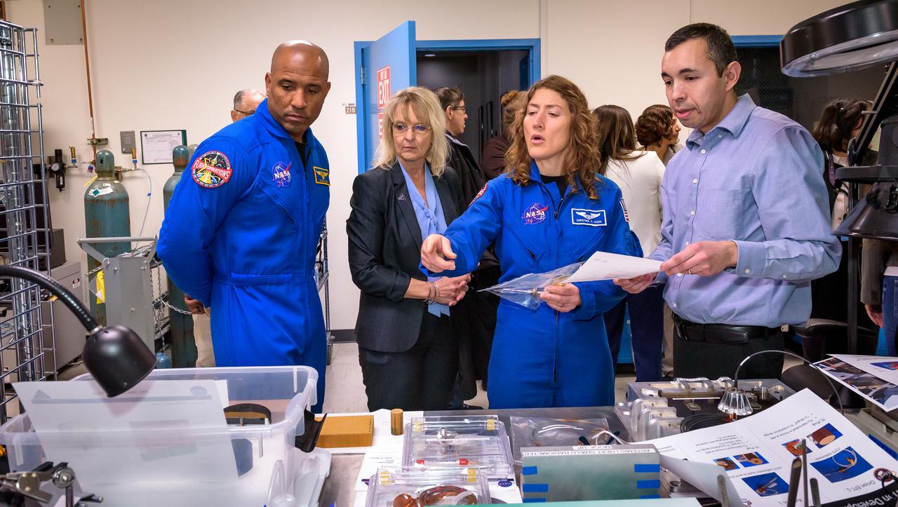
Jose A. B. Santos, right, discusses thermal protection materials with NASA astronaut Victor J. Glover, Orion Deputy Program Manager Debbie Korth, and NASA astronaut Christina Koch in STAR Labs in N242.
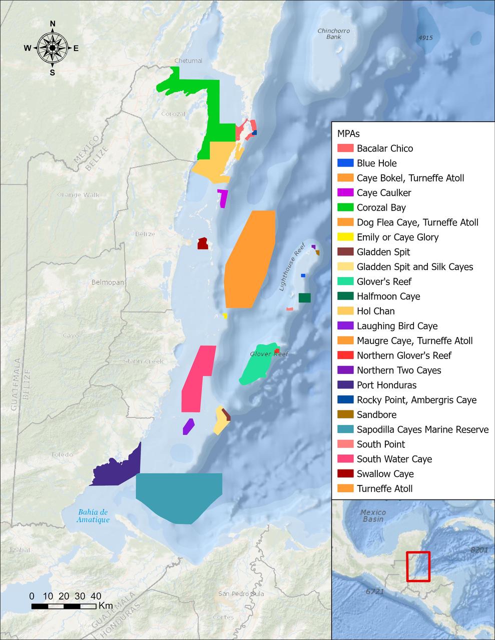
In a paper published in November 2022 in Frontiers in Remote Sensing, researchers at NASA's Jet Propulsion Laboratory, with colleagues in Belize, used data from the Moderate Resolution Imaging Spectroradiometer (MODIS) instrument aboard NASA's Aqua satellite to rank 24 protected marine areas off the Belizean coast based on the risks coral face from murky water and rising temperatures. All the areas are part of the 185-mile-long (298-kilometer-long) Belize Barrier Reef Reserve System, which encompasses a vibrant network of marine environments that supports thousands of animal and plant species and drives the Central American country's largest industry, tourism. The system is one of about 1,200 UNESCO World Heritage sites around the world. Analyzing imagery from 2002 to 2022, researchers developed a coral vulnerability index – a score between 2 and 12 that characterizes the risk to coral, with higher scores signifying greater risk. Their findings could help management authorities protect the reefs from human impacts such as development, overfishing, pollution, and climate change. Port Honduras Marine Reserve, a 156-square-mile (40,000-hectare) protected area in southern Belize, showed the highest coral vulnerability score: 10 out of 12. Based on the index, the study flags Port Honduras, Swallow Caye Wildlife Sanctuary, Sapodilla Cayes Marine Reserve, and Corozal Bay Wildlife Sanctuary as areas for concern. https://photojournal.jpl.nasa.gov/catalog/PIA25862

Goddard technologist Nithin Abraham, a member of the team that has developed a low-cost, low-mass technique for protecting sensitive spacecraft components from outgassed contaminants, studies a paint sample in her laboratory. To read this story go to: <a href="http://www.nasa.gov/topics/technology/features/outgas-tech.html" rel="nofollow">www.nasa.gov/topics/technology/features/outgas-tech.html</a> Credit: NASA/Pat Izzo <b><a href="http://www.nasa.gov/audience/formedia/features/MP_Photo_Guidelines.html" rel="nofollow">NASA image use policy.</a></b> <b><a href="http://www.nasa.gov/centers/goddard/home/index.html" rel="nofollow">NASA Goddard Space Flight Center</a></b> enables NASA’s mission through four scientific endeavors: Earth Science, Heliophysics, Solar System Exploration, and Astrophysics. Goddard plays a leading role in NASA’s accomplishments by contributing compelling scientific knowledge to advance the Agency’s mission. <b>Follow us on <a href="http://twitter.com/NASA_GoddardPix" rel="nofollow">Twitter</a></b> <b>Like us on <a href="http://www.facebook.com/pages/Greenbelt-MD/NASA-Goddard/395013845897?ref=tsd" rel="nofollow">Facebook</a></b> <b>Find us on <a href="http://instagram.com/nasagoddard?vm=grid" rel="nofollow">Instagram</a></b>
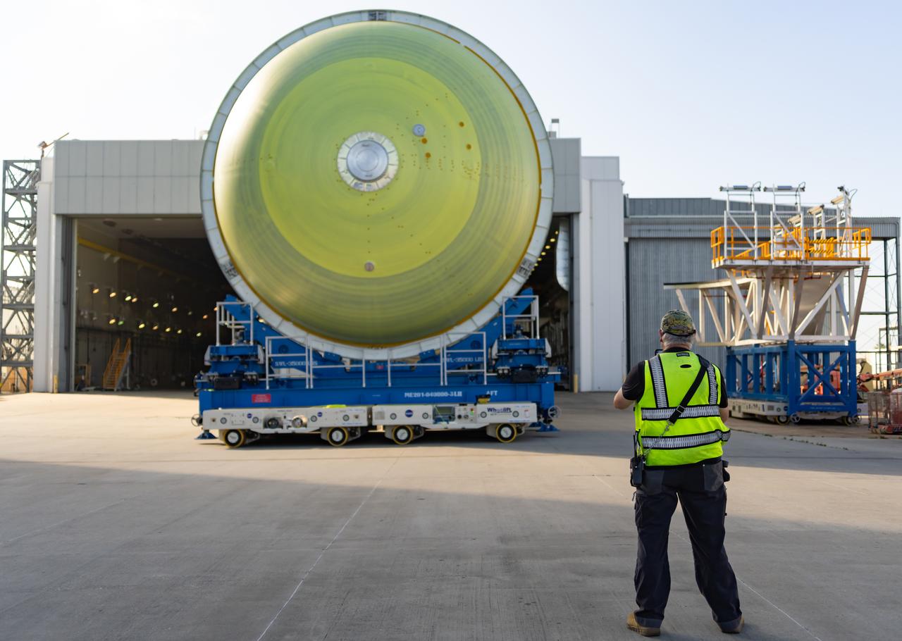
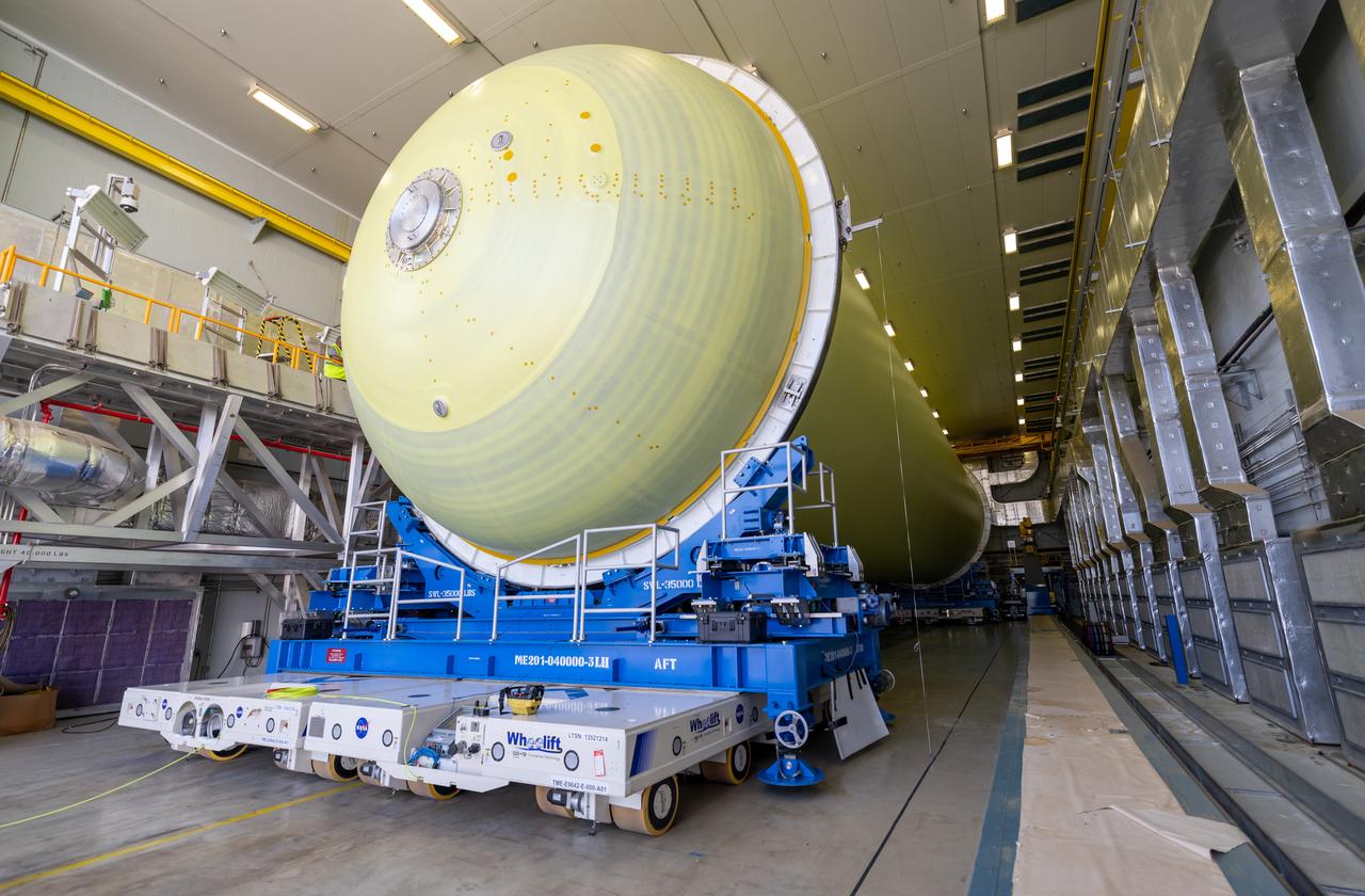
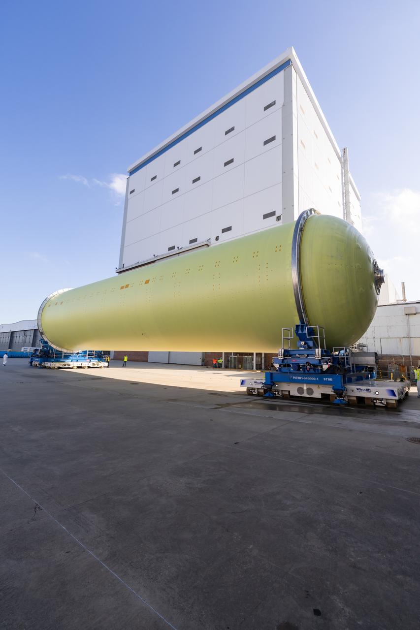
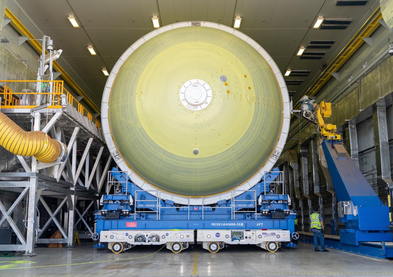
Teams move a liquid hydrogen tank for NASA’s SLS (Space Launch System) rocket out of a priming cell and into an adjacent cell on May 20 at the agency’s Michoud Assembly Facility in New Orleans. Inside the cell, the tank, which will be used on the core stage of NASA’s Artemis III mission, will receive its thermal protection system. The thermal protection system, or spray-on foam insulation, provides protection to the core stage during launch. It is flexible enough to move with the rocket yet can withstand the aerodynamic pressures as the SLS accelerates from 0 to 17,500 mph and soars to more than 100 miles above the Earth. This third-generation insulation is more environmentally friendly and keeps the cryogenic propellant, which powers the rocket’s four RS-25 engines, extremely cold (the liquid hydrogen must remain at minus 423 degrees Fahrenheit/253 degrees Celsius) to remain in its liquid state. When applied the thermal protection system is a light-yellow color, which “tans” once exposed to the Sun’s ultraviolet rays, giving the SLS core stage its signature orange color.
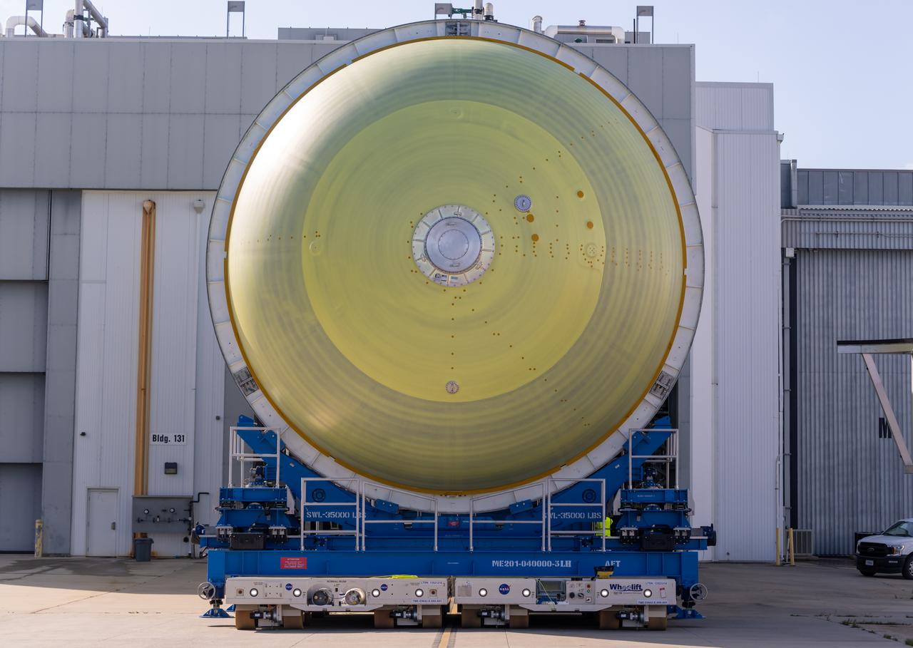
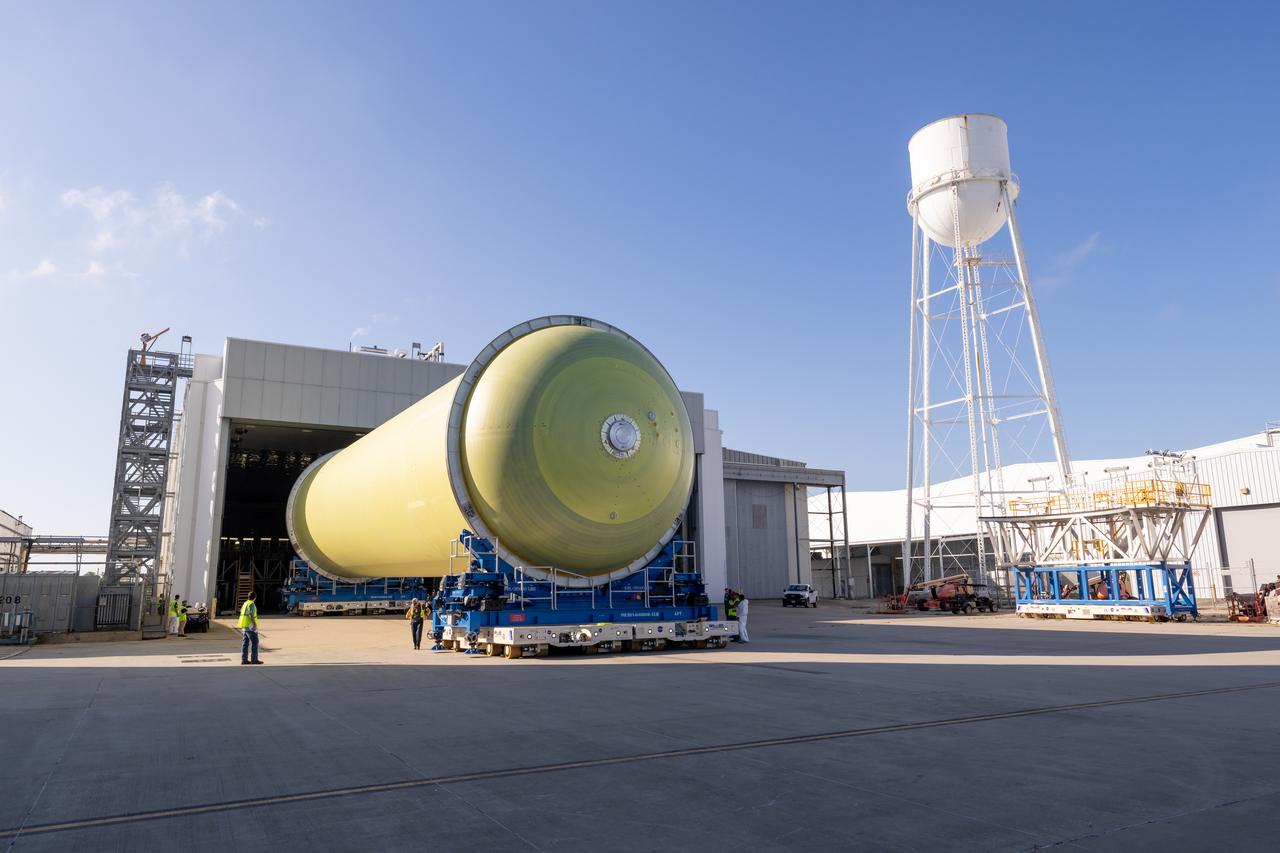
Teams move a liquid hydrogen tank for NASA’s SLS (Space Launch System) rocket out of a priming cell and into an adjacent cell on May 20 at the agency’s Michoud Assembly Facility in New Orleans. Inside the cell, the tank, which will be used on the core stage of NASA’s Artemis III mission, will receive its thermal protection system. The thermal protection system, or spray-on foam insulation, provides protection to the core stage during launch. It is flexible enough to move with the rocket yet can withstand the aerodynamic pressures as the SLS accelerates from 0 to 17,500 mph and soars to more than 100 miles above the Earth. This third-generation insulation is more environmentally friendly and keeps the cryogenic propellant, which powers the rocket’s four RS-25 engines, extremely cold (the liquid hydrogen must remain at minus 423 degrees Fahrenheit/253 degrees Celsius) to remain in its liquid state. When applied the thermal protection system is a light-yellow color, which “tans” once exposed to the Sun’s ultraviolet rays, giving the SLS core stage its signature orange color.
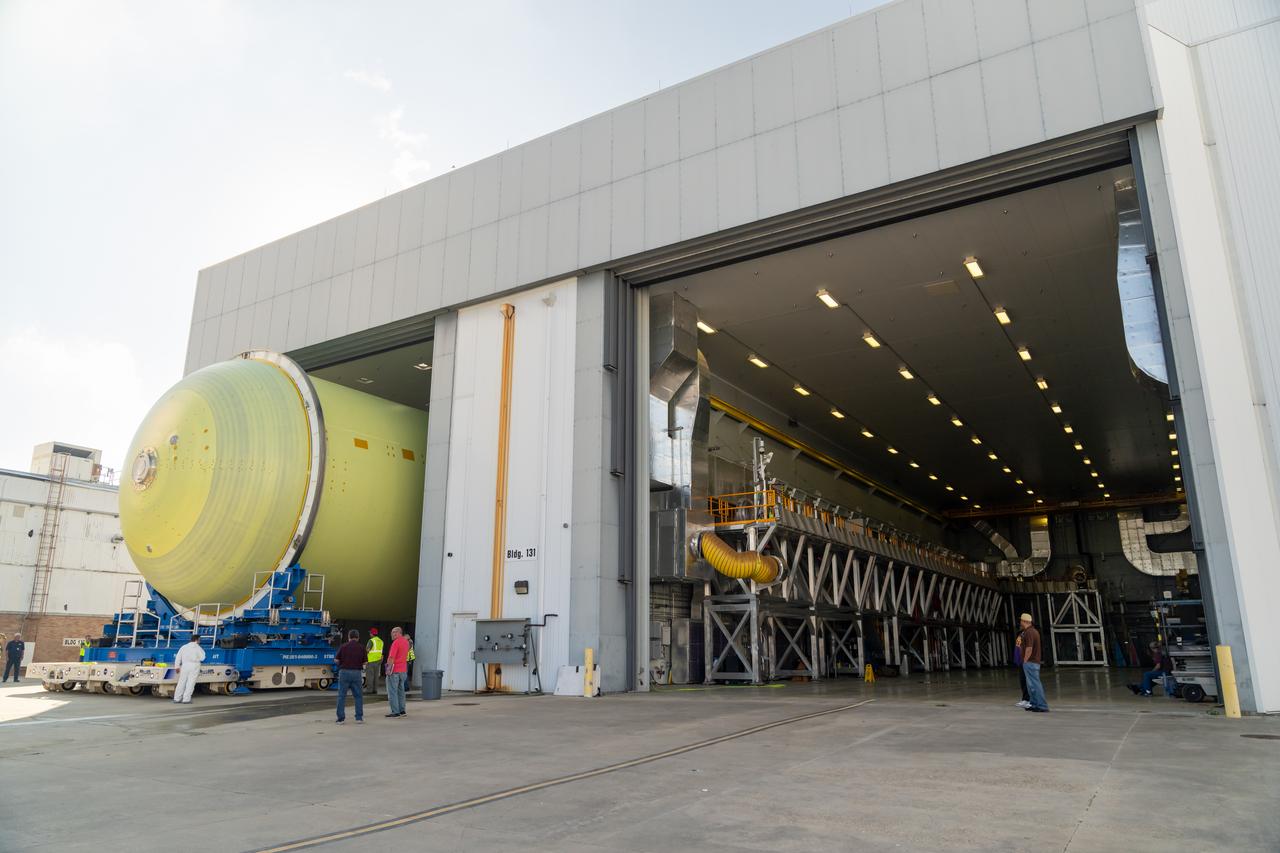
Teams move a liquid hydrogen tank for NASA’s SLS (Space Launch System) rocket out of a priming cell and into an adjacent cell on May 20 at the agency’s Michoud Assembly Facility in New Orleans. Inside the cell, the tank, which will be used on the core stage of NASA’s Artemis III mission, will receive its thermal protection system. The thermal protection system, or spray-on foam insulation, provides protection to the core stage during launch. It is flexible enough to move with the rocket yet can withstand the aerodynamic pressures as the SLS accelerates from 0 to 17,500 mph and soars to more than 100 miles above the Earth. This third-generation insulation is more environmentally friendly and keeps the cryogenic propellant, which powers the rocket’s four RS-25 engines, extremely cold (the liquid hydrogen must remain at minus 423 degrees Fahrenheit/253 degrees Celsius) to remain in its liquid state. When applied the thermal protection system is a light-yellow color, which “tans” once exposed to the Sun’s ultraviolet rays, giving the SLS core stage its signature orange color.
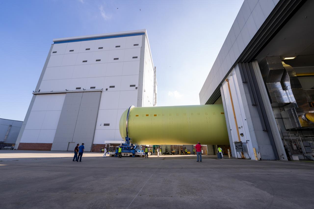
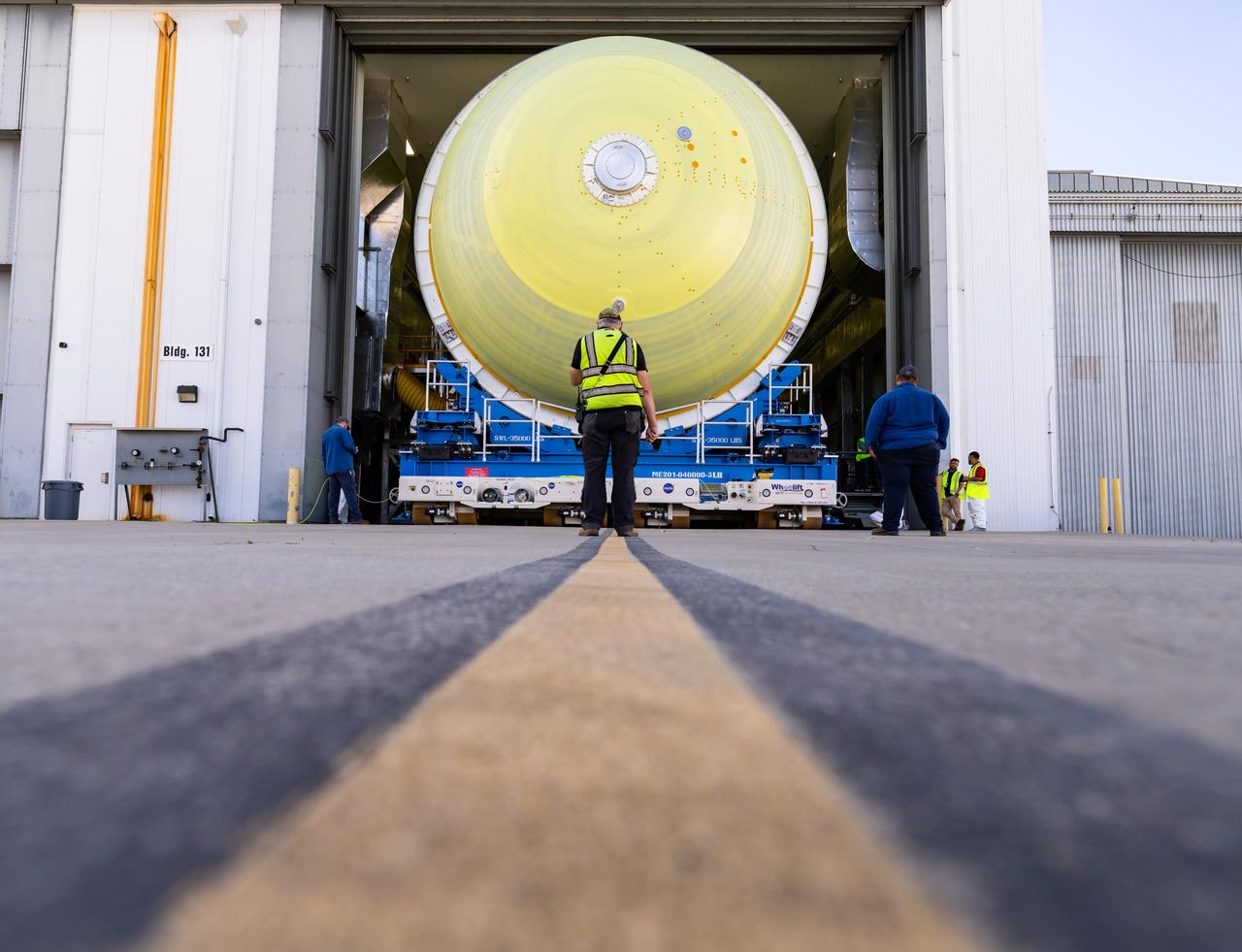
Teams move a liquid hydrogen tank for NASA’s SLS (Space Launch System) rocket out of a priming cell and into an adjacent cell on May 20 at the agency’s Michoud Assembly Facility in New Orleans. Inside the cell, the tank, which will be used on the core stage of NASA’s Artemis III mission, will receive its thermal protection system. The thermal protection system, or spray-on foam insulation, provides protection to the core stage during launch. It is flexible enough to move with the rocket yet can withstand the aerodynamic pressures as the SLS accelerates from 0 to 17,500 mph and soars to more than 100 miles above the Earth. This third-generation insulation is more environmentally friendly and keeps the cryogenic propellant, which powers the rocket’s four RS-25 engines, extremely cold (the liquid hydrogen must remain at minus 423 degrees Fahrenheit/253 degrees Celsius) to remain in its liquid state. When applied the thermal protection system is a light-yellow color, which “tans” once exposed to the Sun’s ultraviolet rays, giving the SLS core stage its signature orange color.
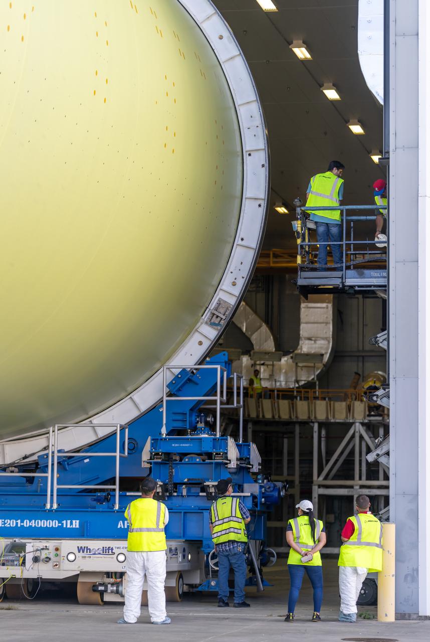
Teams move a liquid hydrogen tank for NASA’s SLS (Space Launch System) rocket out of a priming cell and into an adjacent cell on May 20 at the agency’s Michoud Assembly Facility in New Orleans. Inside the cell, the tank, which will be used on the core stage of NASA’s Artemis III mission, will receive its thermal protection system. The thermal protection system, or spray-on foam insulation, provides protection to the core stage during launch. It is flexible enough to move with the rocket yet can withstand the aerodynamic pressures as the SLS accelerates from 0 to 17,500 mph and soars to more than 100 miles above the Earth. This third-generation insulation is more environmentally friendly and keeps the cryogenic propellant, which powers the rocket’s four RS-25 engines, extremely cold (the liquid hydrogen must remain at minus 423 degrees Fahrenheit/253 degrees Celsius) to remain in its liquid state. When applied the thermal protection system is a light-yellow color, which “tans” once exposed to the Sun’s ultraviolet rays, giving the SLS core stage its signature orange color.
Teams move a liquid hydrogen tank for NASA’s SLS (Space Launch System) rocket out of a priming cell and into an adjacent cell on May 20 at the agency’s Michoud Assembly Facility in New Orleans. Inside the cell, the tank, which will be used on the core stage of NASA’s Artemis III mission, will receive its thermal protection system. The thermal protection system, or spray-on foam insulation, provides protection to the core stage during launch. It is flexible enough to move with the rocket yet can withstand the aerodynamic pressures as the SLS accelerates from 0 to 17,500 mph and soars to more than 100 miles above the Earth. This third-generation insulation is more environmentally friendly and keeps the cryogenic propellant, which powers the rocket’s four RS-25 engines, extremely cold (the liquid hydrogen must remain at minus 423 degrees Fahrenheit/253 degrees Celsius) to remain in its liquid state. When applied the thermal protection system is a light-yellow color, which “tans” once exposed to the Sun’s ultraviolet rays, giving the SLS core stage its signature orange color.
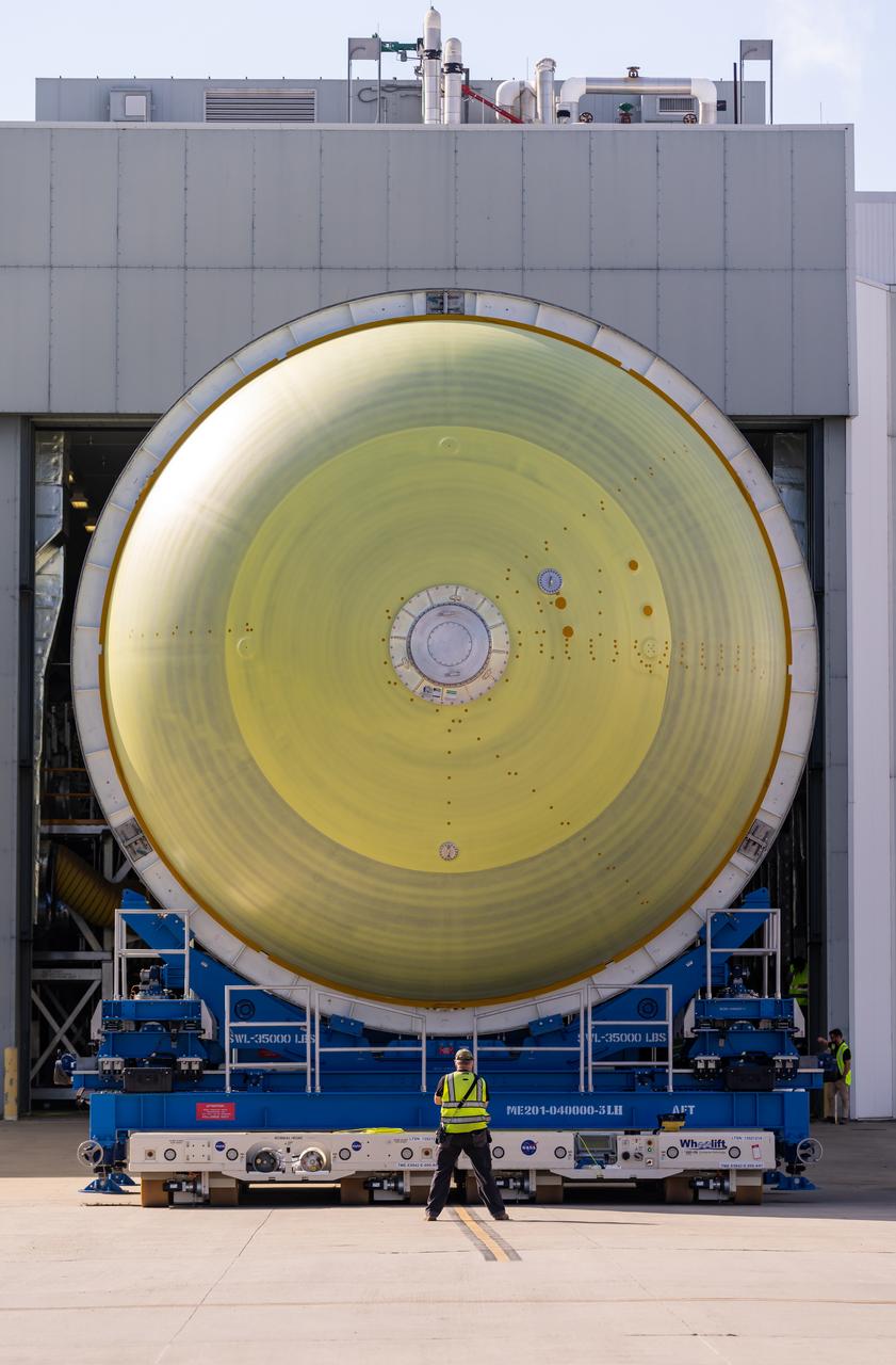
Teams move a liquid hydrogen tank for NASA’s SLS (Space Launch System) rocket out of a priming cell and into an adjacent cell on May 20 at the agency’s Michoud Assembly Facility in New Orleans. Inside the cell, the tank, which will be used on the core stage of NASA’s Artemis III mission, will receive its thermal protection system. The thermal protection system, or spray-on foam insulation, provides protection to the core stage during launch. It is flexible enough to move with the rocket yet can withstand the aerodynamic pressures as the SLS accelerates from 0 to 17,500 mph and soars to more than 100 miles above the Earth. This third-generation insulation is more environmentally friendly and keeps the cryogenic propellant, which powers the rocket’s four RS-25 engines, extremely cold (the liquid hydrogen must remain at minus 423 degrees Fahrenheit/253 degrees Celsius) to remain in its liquid state. When applied the thermal protection system is a light-yellow color, which “tans” once exposed to the Sun’s ultraviolet rays, giving the SLS core stage its signature orange color.
Teams move a liquid hydrogen tank for NASA’s SLS (Space Launch System) rocket out of a priming cell and into an adjacent cell on May 20 at the agency’s Michoud Assembly Facility in New Orleans. Inside the cell, the tank, which will be used on the core stage of NASA’s Artemis III mission, will receive its thermal protection system. The thermal protection system, or spray-on foam insulation, provides protection to the core stage during launch. It is flexible enough to move with the rocket yet can withstand the aerodynamic pressures as the SLS accelerates from 0 to 17,500 mph and soars to more than 100 miles above the Earth. This third-generation insulation is more environmentally friendly and keeps the cryogenic propellant, which powers the rocket’s four RS-25 engines, extremely cold (the liquid hydrogen must remain at minus 423 degrees Fahrenheit/253 degrees Celsius) to remain in its liquid state. When applied the thermal protection system is a light-yellow color, which “tans” once exposed to the Sun’s ultraviolet rays, giving the SLS core stage its signature orange color.
Teams move a liquid hydrogen tank for NASA’s SLS (Space Launch System) rocket out of a priming cell and into an adjacent cell on May 20 at the agency’s Michoud Assembly Facility in New Orleans. Inside the cell, the tank, which will be used on the core stage of NASA’s Artemis III mission, will receive its thermal protection system. The thermal protection system, or spray-on foam insulation, provides protection to the core stage during launch. It is flexible enough to move with the rocket yet can withstand the aerodynamic pressures as the SLS accelerates from 0 to 17,500 mph and soars to more than 100 miles above the Earth. This third-generation insulation is more environmentally friendly and keeps the cryogenic propellant, which powers the rocket’s four RS-25 engines, extremely cold (the liquid hydrogen must remain at minus 423 degrees Fahrenheit/253 degrees Celsius) to remain in its liquid state. When applied the thermal protection system is a light-yellow color, which “tans” once exposed to the Sun’s ultraviolet rays, giving the SLS core stage its signature orange color.
Teams move a liquid hydrogen tank for NASA’s SLS (Space Launch System) rocket out of a priming cell and into an adjacent cell on May 20 at the agency’s Michoud Assembly Facility in New Orleans. Inside the cell, the tank, which will be used on the core stage of NASA’s Artemis III mission, will receive its thermal protection system. The thermal protection system, or spray-on foam insulation, provides protection to the core stage during launch. It is flexible enough to move with the rocket yet can withstand the aerodynamic pressures as the SLS accelerates from 0 to 17,500 mph and soars to more than 100 miles above the Earth. This third-generation insulation is more environmentally friendly and keeps the cryogenic propellant, which powers the rocket’s four RS-25 engines, extremely cold (the liquid hydrogen must remain at minus 423 degrees Fahrenheit/253 degrees Celsius) to remain in its liquid state. When applied the thermal protection system is a light-yellow color, which “tans” once exposed to the Sun’s ultraviolet rays, giving the SLS core stage its signature orange color.
Teams move a liquid hydrogen tank for NASA’s SLS (Space Launch System) rocket out of a priming cell and into an adjacent cell on May 20 at the agency’s Michoud Assembly Facility in New Orleans. Inside the cell, the tank, which will be used on the core stage of NASA’s Artemis III mission, will receive its thermal protection system. The thermal protection system, or spray-on foam insulation, provides protection to the core stage during launch. It is flexible enough to move with the rocket yet can withstand the aerodynamic pressures as the SLS accelerates from 0 to 17,500 mph and soars to more than 100 miles above the Earth. This third-generation insulation is more environmentally friendly and keeps the cryogenic propellant, which powers the rocket’s four RS-25 engines, extremely cold (the liquid hydrogen must remain at minus 423 degrees Fahrenheit/253 degrees Celsius) to remain in its liquid state. When applied the thermal protection system is a light-yellow color, which “tans” once exposed to the Sun’s ultraviolet rays, giving the SLS core stage its signature orange color.
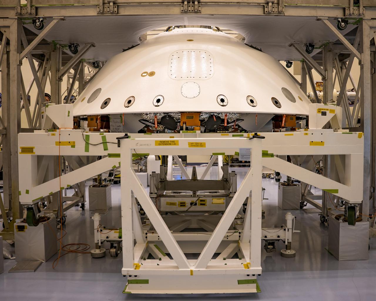
The cone-shaped back shell for NASA's Perseverance rover mission sits on a support structure in this April 29, 2020, image from Kennedy Space Center in Florida. Along with the heat shield, the back shell provides protection for the rover and descent stage during Martian atmospheric entry. Portions of the descent stage and rover, stacked one on top of the other, can be seen in the open area directly below the lower edge of back shell. https://photojournal.jpl.nasa.gov/catalog/PIA23885
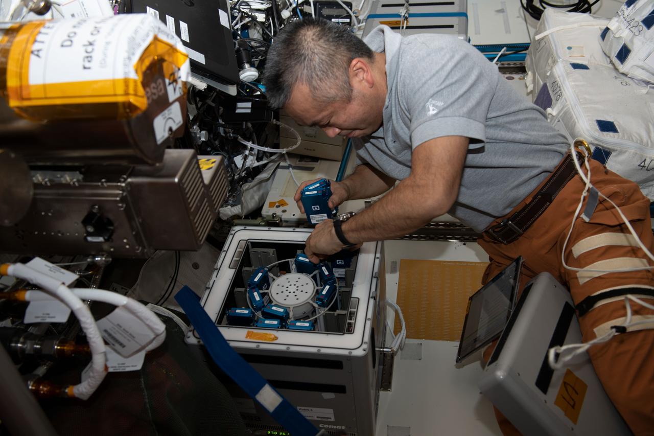
iss068e021831 (Nov. 14, 2022) --- Astronaut and Expedition 68 Flight Engineer Koichi Wakata of the Japan Aerospace Exploration Agency (JAXA) removes experiment containers from inside the Columbus laboratory module's Kubik research facility, a temperature-controlled incubator. The experiment containers are part of the Antioxidation Protection experiment that explores neuronal cells involved in the cognitive and motor functions of humans both in space and on Earth. Credit: Nicole Mann/NASA
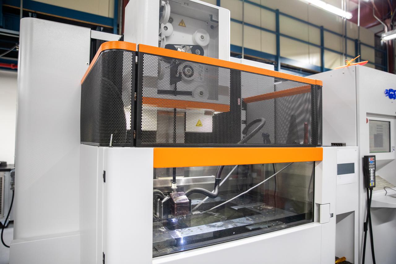
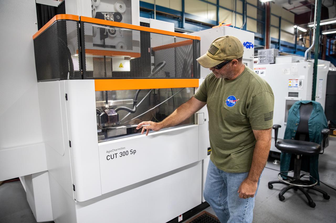
Testing of the Plasma Rapid Oxidation Technique for Extending Component Tenability (PROTECT) experiment is underway inside the Prototype Development Laboratory at NASA’s Kennedy Space Center in Florida on Nov. 2, 2022. Plasma electrolytic oxidation is a surface coating technology that produces oxide layers on the surface of light metals and their alloys to improve their performance characteristics. These coatings are tailored to provide a combination of characteristics such as corrosion protection, wear resistance, thermal management, extreme hardness, and fatigue performance. PROTECT is expected to demonstrate a ten percent improved fatigue performance and a 70 percent improvement in corrosion characteristics on the interior of treated 3-D printed metallic parts when compared to non-treated parts. PROTECT could be applied on spacecraft and launch vehicles.
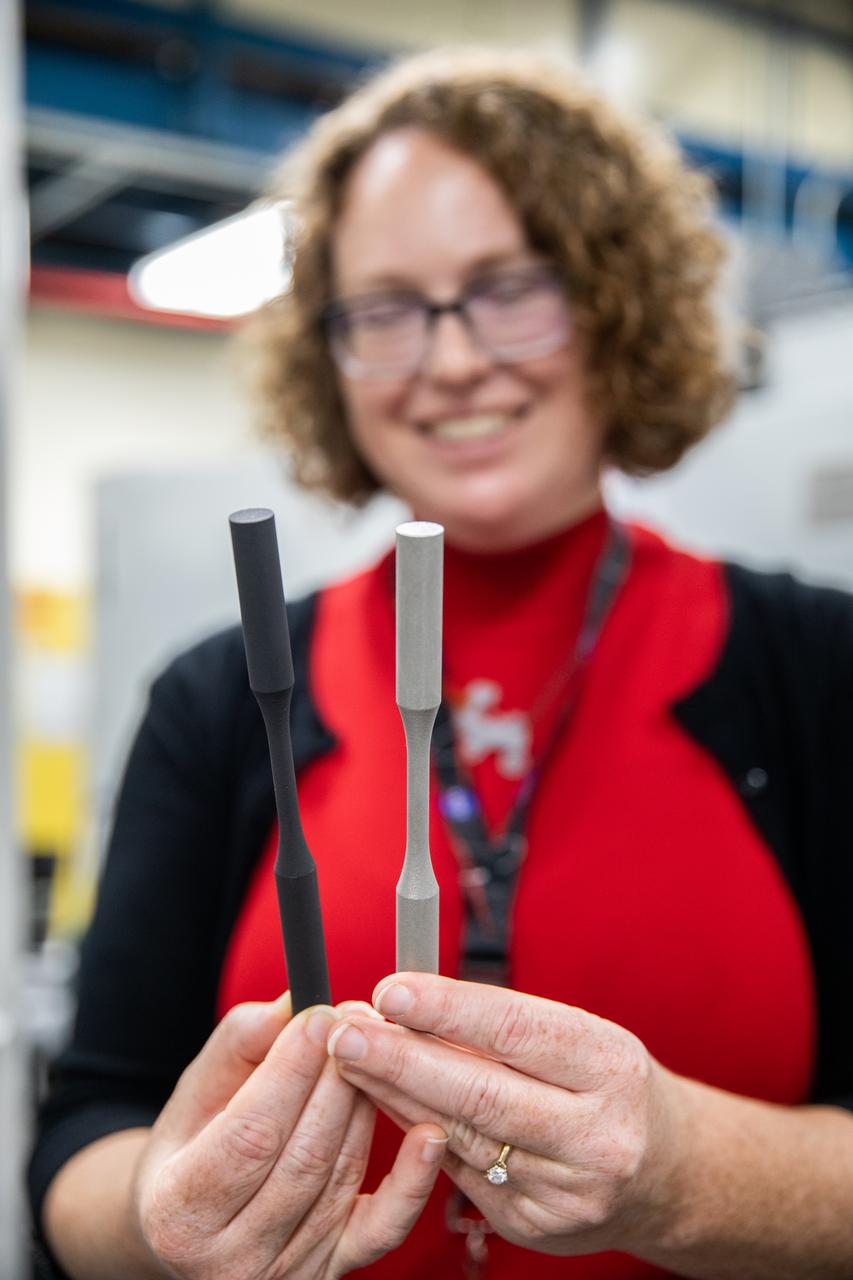
Dr. Jennifer Williams, a NASA research chemical engineer, displays two fatigue samples that will be tested in the Plasma Rapid Oxidation Technique for Extending Component Tenability (PROTECT) experiments inside the Prototype Laboratory at NASA’s Kennedy Space Center in Florida on Nov. 2, 2022. Plasma electrolytic oxidation is a surface coating technology that produces oxide layers on the surface of light metals and their alloys to improve their performance characteristics. These coatings are tailored to provide a combination of characteristics such as corrosion protection, wear resistance, thermal management, extreme hardness, and fatigue performance. PROTECT is expected to demonstrate a 10 percent improved fatigue performance and a 70 percent improvement in corrosion characteristics on the interior of treated 3-D printed metallic parts when compared to non-treated parts. PROTECT could be applied to spacecraft and launch vehicles.
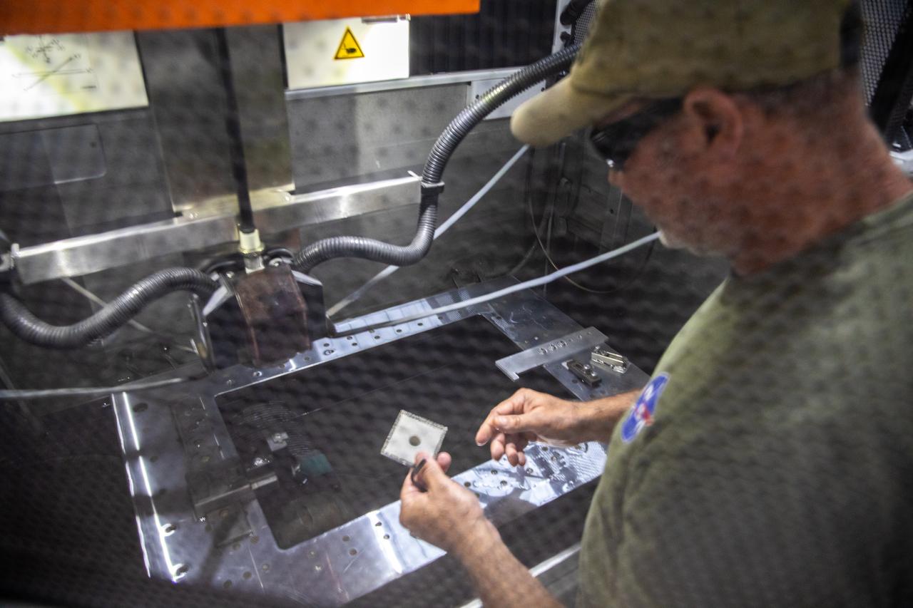
Gerard Moscoso, a mechanical engineer technician with NASA, prepares a sample for testing for the Plasma Rapid Oxidation Technique for Extending Component Tenability (PROTECT) project inside the Prototype Development Laboratory at NASA’s Kennedy Space Center in Florida on Nov. 2, 2022. Plasma electrolytic oxidation is a surface coating technology that produces oxide layers on the surface of light metals and their alloys to improve their performance characteristics. These coatings are tailored to provide a combination of characteristics such as corrosion protection, wear resistance, thermal management, extreme hardness, and fatigue performance. PROTECT is expected to demonstrate a 10 percent improved fatigue performance and a 70 percent improvement in corrosion characteristics on the interior of treated 3-D printed metallic parts when compared to non-treated parts. PROTECT could be applied on spacecraft and launch vehicles.

Dr. Jennifer Williams, a NASA research chemical engineer, is inside the Prototype Development Laboratory at NASA’s Kennedy Space Center in Florida to begin testing on the Plasma Rapid Oxidation Technique for Extending Component Tenability (PROTECT) project on Nov. 2, 2022. Plasma electrolytic oxidation is a surface coating technology that produces oxide layers on the surface of light metals and their alloys to improve their performance characteristics. These coatings are tailored to provide a combination of characteristics such as corrosion protection, wear resistance, thermal management, extreme hardness, and fatigue performance. PROTECT is expected to demonstrate a 10 percent improved fatigue performance and a 70 percent improvement in corrosion characteristics on the interior of treated 3-D printed metallic parts when compared to non-treated parts. PROTECT could be applied to spacecraft and launch vehicles.
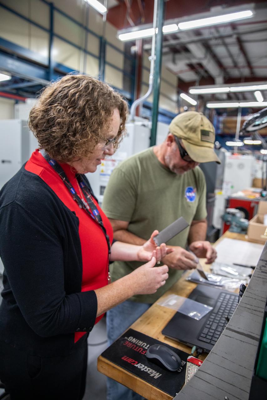
From left, Dr. Jennifer Williams, a NASA research chemical engineer, and Gerard Moscoso, a mechanical engineer technician, inspect specimens prepared forthe Plasma Rapid Oxidation Technique for Extending Component Tenability (PROTECT) experiment inside the Prototype Development Laboratory at NASA’s Kennedy Space Center in Florida on Nov. 2, 2022. Plasma electrolytic oxidation is a surface coating technology that produces oxide layers on the surface of light metals and their alloys to improve their performance characteristics. These coatings are tailored to provide a combination of characteristics such as corrosion protection, wear resistance, thermal management, extreme hardness, and fatigue performance. PROTECT is expected to demonstrate a 10 percent improved fatigue performance and a 70 percent improvement in corrosion characteristics on the interior of treated 3-D printed metallic parts when compared to non-treated parts. PROTECT could be applied used on spacecraft and launch vehicles.
Gerard Moscoso, a mechanical engineer technician with NASA, prepares the Plasma Rapid Oxidation Technique for Extending Component Tenability (PROTECT) specimens for testing inside the Prototype Development Laboratory at NASA’s Kennedy Space Center in Florida on Nov. 2, 2022. Plasma electrolytic oxidation is a surface coating technology that produces oxide layers on the surface of light metals and their alloys to improve their performance characteristics. These coatings are tailored to provide a combination of characteristics such as corrosion protection, wear resistance, thermal management, extreme hardness, and fatigue performance. PROTECT is expected to demonstrate a 10 percent improved fatigue performance and a 70 percent improvement in corrosion characteristics on the interior of treated 3-D printed metallic parts when compared to non-treated parts. PROTECT could be applied on spacecraft and launch vehicles.
Gerard Moscoso, a mechanical engineer technician with NASA, handles a sample that is being prepared for fatigue and corrosion testing for the Plasma Rapid Oxidation Technique for Extending Component Tenability (PROTECT) project inside the Prototype Development Laboratory at NASA’s Kennedy Space Center in Florida on Nov. 2, 2022. Plasma electrolytic oxidation is a surface coating technology that produces oxide layers on the surface of light metals and their alloys to improve their performance characteristics. These coatings are tailored to provide a combination of characteristics such as corrosion protection, wear resistance, thermal management, extreme hardness, and fatigue performance. PROTECT is expected to demonstrate a ten percent improved fatigue performance and a 70 percent improvement in corrosion characteristics on the interior of treated 3-D printed metallic parts when compared to non-treated parts. PROTECT could be applied on spacecraft and launch vehicles.
Testing of the Plasma Rapid Oxidation Technique for Extending Component Tenability (PROTECT) experiment is underway inside the Prototype Development Laboratory at NASA’s Kennedy Space Center in Florida on Nov. 2, 2022. Plasma electrolytic oxidation is a surface coating technology that produces oxide layers on the surface of light metals and their alloys to improve their performance characteristics. These coatings are tailored to provide a combination of characteristics such as corrosion protection, wear resistance, thermal management, extreme hardness, and fatigue performance. PROTECT is expected to demonstrate a 10 percent improved fatigue performance and a 70 percent improvement in corrosion characteristics on the interior of treated 3-D printed metallic parts when compared to non-treated parts. PROTECT could be applied on spacecraft and launch vehicles.

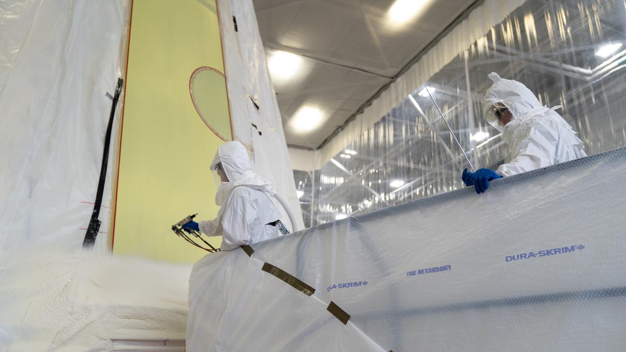
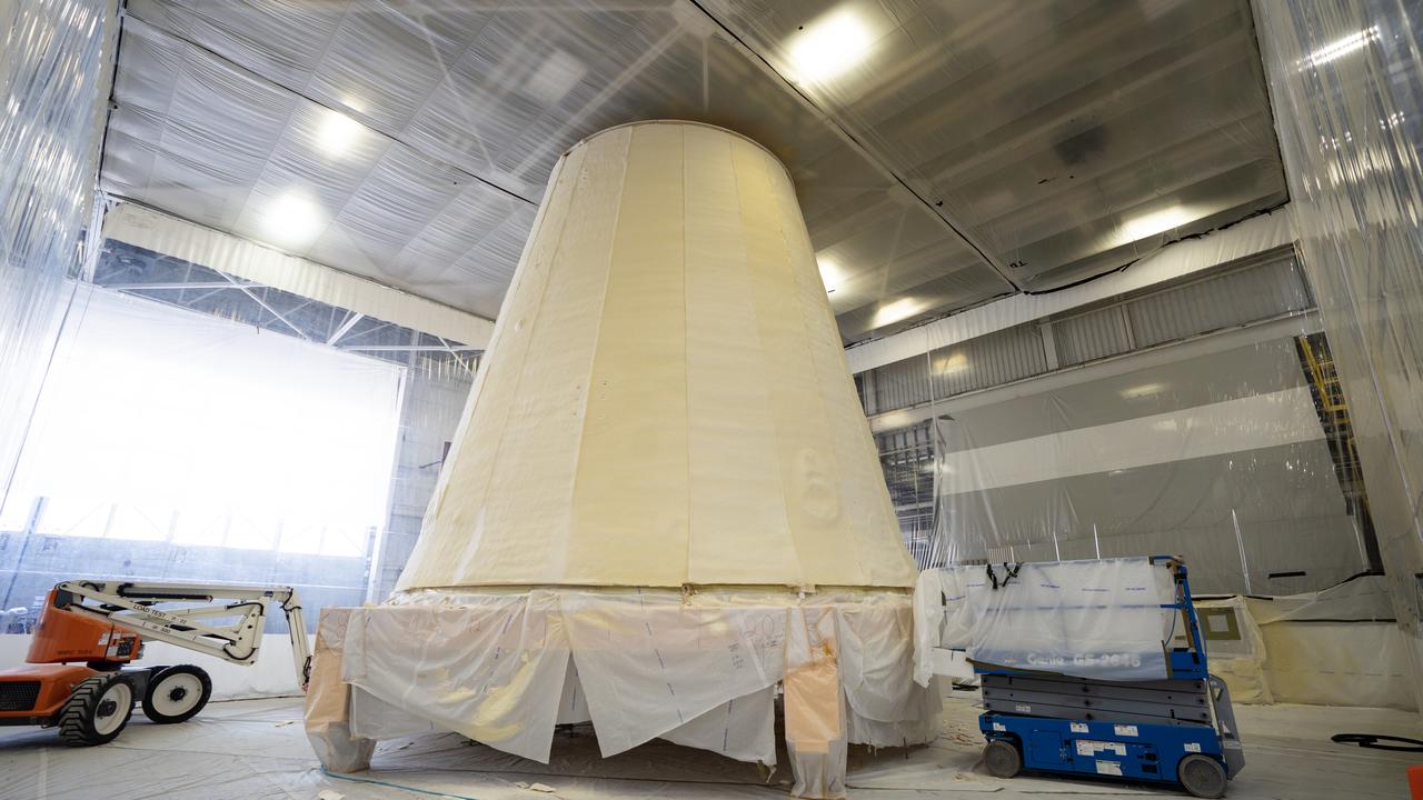
These photos show how technicians at NASA’s Marshall Space Flight Center in Huntsville, Alabama, have applied the thermal protection system material to the launch vehicle stage adapter (LVSA) of NASA’s SLS (Space Launch System) rocket for Artemis III, which will land astronauts on the Moon to advance long-term lunar exploration and scientific discovery and inspire the Artemis Generation. The LVSA is a cone-shaped element that connects the mega rocket’s core stage to its interim cryogenic propulsion stage (ICPS), partially enclosing it and protecting its avionics and electrical systems from the extreme pressures, sounds, and temperatures during launch and flight. Teams at Marshall began applying the thermal protection system material in the spring of 2023. Unlike other parts of the SLS rocket, the thermal protection system material for the LVSA is applied entirely by hand using a spray gun. During application, the technicians use a thin measuring rod to gauge the proper thickness. Once the thermal protection system has cured, certain areas are sanded down to meet parameters. The entire process takes several months. The LVSA is fully manufactured at Marshall by NASA, lead contractor Teledyne Brown Engineering, and the Jacobs Space Group’s ESSCA contract. The LVSA for Artemis III is the last of its kind as future SLS rockets will transition to its next, more powerful Block 1B configuration beginning with Artemis IV. NASA is working to land the first woman and first person of color on the Moon under Artemis. SLS is part of NASA’s backbone for deep space exploration, along with the Orion spacecraft, advanced spacesuits and rovers, the Gateway in orbit around the Moon, and commercial human landing systems. SLS is the only rocket that can send Orion, astronauts, and supplies to the Moon in a single mission.
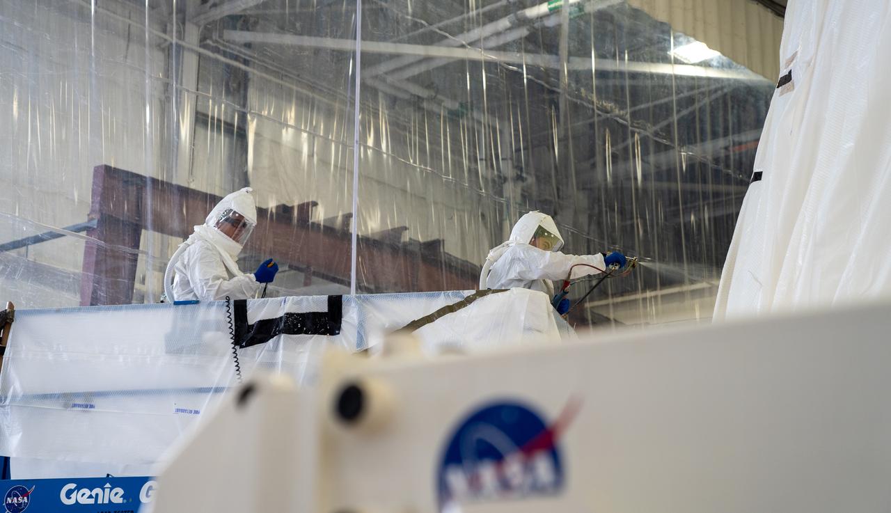
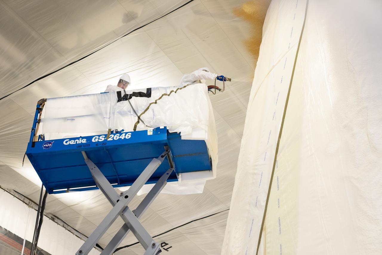
These photos show how technicians at NASA’s Marshall Space Flight Center in Huntsville, Alabama, have applied the thermal protection system material to the launch vehicle stage adapter (LVSA) of NASA’s SLS (Space Launch System) rocket for Artemis III, which will land astronauts on the Moon to advance long-term lunar exploration and scientific discovery and inspire the Artemis Generation. The LVSA is a cone-shaped element that connects the mega rocket’s core stage to its interim cryogenic propulsion stage (ICPS), partially enclosing it and protecting its avionics and electrical systems from the extreme pressures, sounds, and temperatures during launch and flight. Teams at Marshall began applying the thermal protection system material in the spring of 2023. Unlike other parts of the SLS rocket, the thermal protection system material for the LVSA is applied entirely by hand using a spray gun. During application, the technicians use a thin measuring rod to gauge the proper thickness. Once the thermal protection system has cured, certain areas are sanded down to meet parameters. The entire process takes several months. The LVSA is fully manufactured at Marshall by NASA, lead contractor Teledyne Brown Engineering, and the Jacobs Space Group’s ESSCA contract. The LVSA for Artemis III is the last of its kind as future SLS rockets will transition to its next, more powerful Block 1B configuration beginning with Artemis IV. NASA is working to land the first woman and first person of color on the Moon under Artemis. SLS is part of NASA’s backbone for deep space exploration, along with the Orion spacecraft, advanced spacesuits and rovers, the Gateway in orbit around the Moon, and commercial human landing systems. SLS is the only rocket that can send Orion, astronauts, and supplies to the Moon in a single mission.
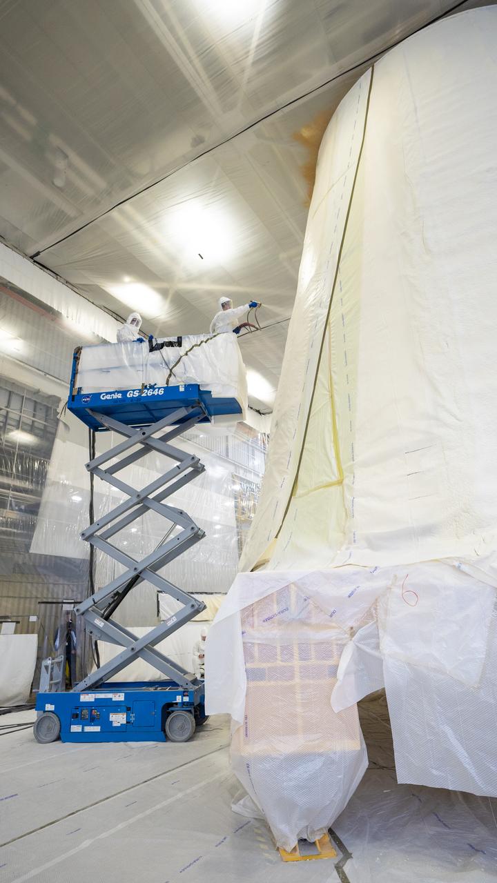
These photos show how technicians at NASA’s Marshall Space Flight Center in Huntsville, Alabama, have applied the thermal protection system material to the launch vehicle stage adapter (LVSA) of NASA’s SLS (Space Launch System) rocket for Artemis III, which will land astronauts on the Moon to advance long-term lunar exploration and scientific discovery and inspire the Artemis Generation. The LVSA is a cone-shaped element that connects the mega rocket’s core stage to its interim cryogenic propulsion stage (ICPS), partially enclosing it and protecting its avionics and electrical systems from the extreme pressures, sounds, and temperatures during launch and flight. Teams at Marshall began applying the thermal protection system material in the spring of 2023. Unlike other parts of the SLS rocket, the thermal protection system material for the LVSA is applied entirely by hand using a spray gun. During application, the technicians use a thin measuring rod to gauge the proper thickness. Once the thermal protection system has cured, certain areas are sanded down to meet parameters. The entire process takes several months. The LVSA is fully manufactured at Marshall by NASA, lead contractor Teledyne Brown Engineering, and the Jacobs Space Group’s ESSCA contract. The LVSA for Artemis III is the last of its kind as future SLS rockets will transition to its next, more powerful Block 1B configuration beginning with Artemis IV. NASA is working to land the first woman and first person of color on the Moon under Artemis. SLS is part of NASA’s backbone for deep space exploration, along with the Orion spacecraft, advanced spacesuits and rovers, the Gateway in orbit around the Moon, and commercial human landing systems. SLS is the only rocket that can send Orion, astronauts, and supplies to the Moon in a single mission.
These photos show how technicians at NASA’s Marshall Space Flight Center in Huntsville, Alabama, have applied the thermal protection system material to the launch vehicle stage adapter (LVSA) of NASA’s SLS (Space Launch System) rocket for Artemis III, which will land astronauts on the Moon to advance long-term lunar exploration and scientific discovery and inspire the Artemis Generation. The LVSA is a cone-shaped element that connects the mega rocket’s core stage to its interim cryogenic propulsion stage (ICPS), partially enclosing it and protecting its avionics and electrical systems from the extreme pressures, sounds, and temperatures during launch and flight. Teams at Marshall began applying the thermal protection system material in the spring of 2023. Unlike other parts of the SLS rocket, the thermal protection system material for the LVSA is applied entirely by hand using a spray gun. During application, the technicians use a thin measuring rod to gauge the proper thickness. Once the thermal protection system has cured, certain areas are sanded down to meet parameters. The entire process takes several months. The LVSA is fully manufactured at Marshall by NASA, lead contractor Teledyne Brown Engineering, and the Jacobs Space Group’s ESSCA contract. The LVSA for Artemis III is the last of its kind as future SLS rockets will transition to its next, more powerful Block 1B configuration beginning with Artemis IV. NASA is working to land the first woman and first person of color on the Moon under Artemis. SLS is part of NASA’s backbone for deep space exploration, along with the Orion spacecraft, advanced spacesuits and rovers, the Gateway in orbit around the Moon, and commercial human landing systems. SLS is the only rocket that can send Orion, astronauts, and supplies to the Moon in a single mission.
These photos show how technicians at NASA’s Marshall Space Flight Center in Huntsville, Alabama, have applied the thermal protection system material to the launch vehicle stage adapter (LVSA) of NASA’s SLS (Space Launch System) rocket for Artemis III, which will land astronauts on the Moon to advance long-term lunar exploration and scientific discovery and inspire the Artemis Generation. The LVSA is a cone-shaped element that connects the mega rocket’s core stage to its interim cryogenic propulsion stage (ICPS), partially enclosing it and protecting its avionics and electrical systems from the extreme pressures, sounds, and temperatures during launch and flight. Teams at Marshall began applying the thermal protection system material in the spring of 2023. Unlike other parts of the SLS rocket, the thermal protection system material for the LVSA is applied entirely by hand using a spray gun. During application, the technicians use a thin measuring rod to gauge the proper thickness. Once the thermal protection system has cured, certain areas are sanded down to meet parameters. The entire process takes several months. The LVSA is fully manufactured at Marshall by NASA, lead contractor Teledyne Brown Engineering, and the Jacobs Space Group’s ESSCA contract. The LVSA for Artemis III is the last of its kind as future SLS rockets will transition to its next, more powerful Block 1B configuration beginning with Artemis IV. NASA is working to land the first woman and first person of color on the Moon under Artemis. SLS is part of NASA’s backbone for deep space exploration, along with the Orion spacecraft, advanced spacesuits and rovers, the Gateway in orbit around the Moon, and commercial human landing systems. SLS is the only rocket that can send Orion, astronauts, and supplies to the Moon in a single mission.
These photos show how technicians at NASA’s Marshall Space Flight Center in Huntsville, Alabama, have applied the thermal protection system material to the launch vehicle stage adapter (LVSA) of NASA’s SLS (Space Launch System) rocket for Artemis III, which will land astronauts on the Moon to advance long-term lunar exploration and scientific discovery and inspire the Artemis Generation. The LVSA is a cone-shaped element that connects the mega rocket’s core stage to its interim cryogenic propulsion stage (ICPS), partially enclosing it and protecting its avionics and electrical systems from the extreme pressures, sounds, and temperatures during launch and flight. Teams at Marshall began applying the thermal protection system material in the spring of 2023. Unlike other parts of the SLS rocket, the thermal protection system material for the LVSA is applied entirely by hand using a spray gun. During application, the technicians use a thin measuring rod to gauge the proper thickness. Once the thermal protection system has cured, certain areas are sanded down to meet parameters. The entire process takes several months. The LVSA is fully manufactured at Marshall by NASA, lead contractor Teledyne Brown Engineering, and the Jacobs Space Group’s ESSCA contract. The LVSA for Artemis III is the last of its kind as future SLS rockets will transition to its next, more powerful Block 1B configuration beginning with Artemis IV. NASA is working to land the first woman and first person of color on the Moon under Artemis. SLS is part of NASA’s backbone for deep space exploration, along with the Orion spacecraft, advanced spacesuits and rovers, the Gateway in orbit around the Moon, and commercial human landing systems. SLS is the only rocket that can send Orion, astronauts, and supplies to the Moon in a single mission.
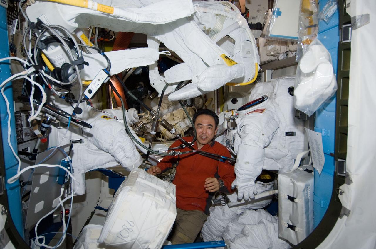
ISS029-E-011030 (26 Sept. 2011) --- Japan Aerospace Exploration Agency astronaut Satoshi Furukawa, Expedition 29 flight engineer, performs protective maintenance on Extravehicular Mobility Unit (EMU) spacesuits in the Quest airlock of the International Space Station.
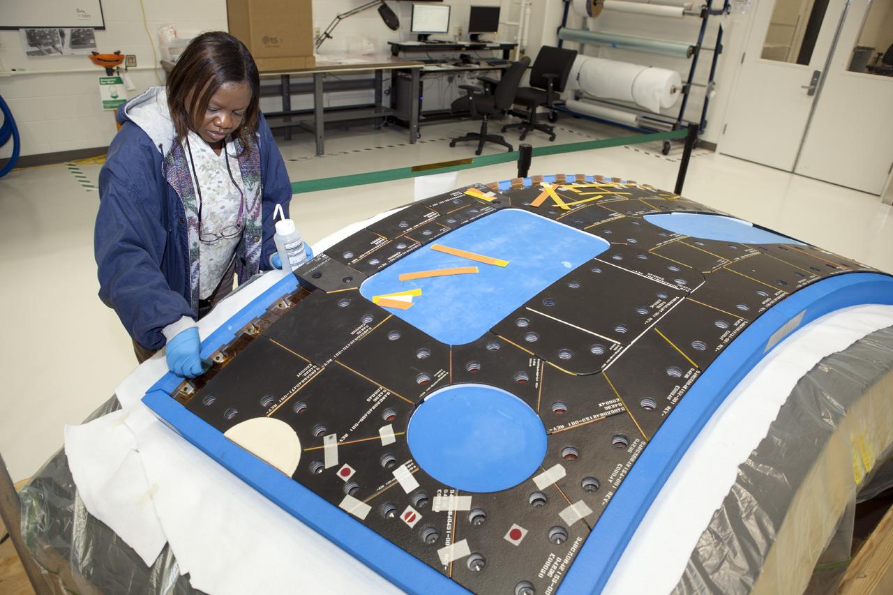
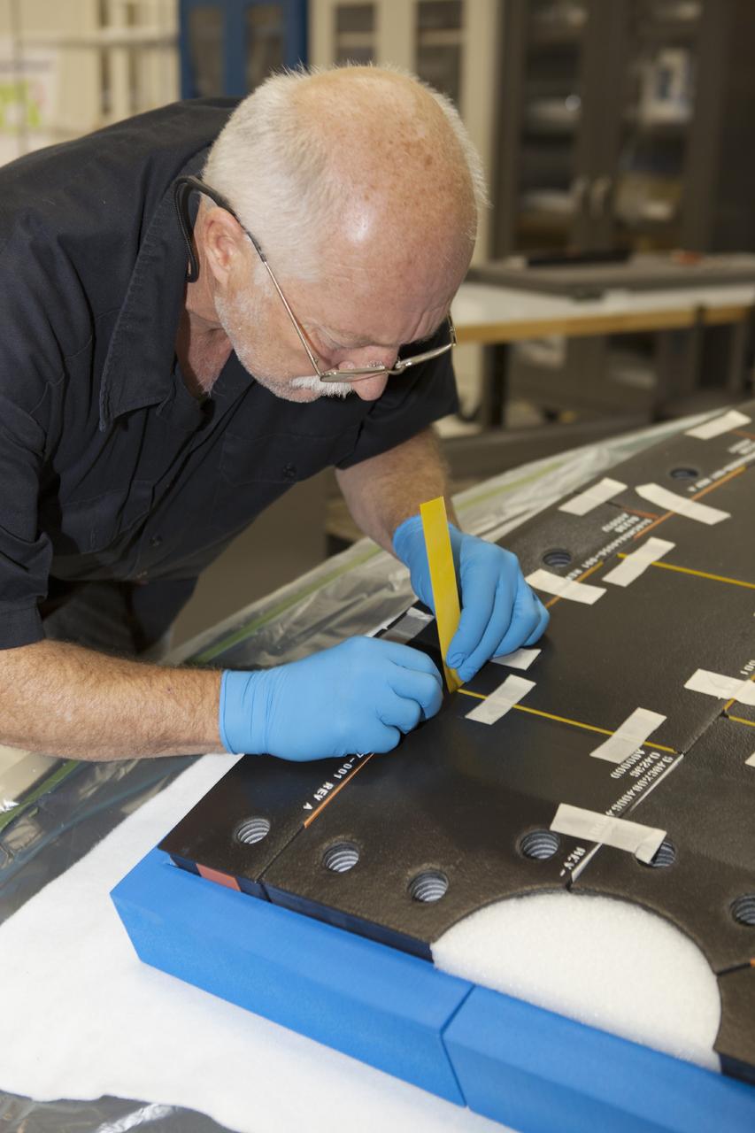
CAPE CANAVERAL, Fla. – Inside the Operations and Checkout Building high bay at NASA’s Kennedy Space Center in Florida, a tile technician works on a section of thermal protection system tiles that will be installed on the Orion crew module. Orion is the exploration spacecraft designed to carry astronauts to destinations not yet explored by humans, including an asteroid and Mars. It will have emergency abort capability, sustain the crew during space travel and provide safe re-entry from deep space return velocities. The first unpiloted test flight of the Orion is scheduled to launch in 2014 atop a Delta IV rocket and in 2017 on NASA’s Space Launch System rocket. For more information, visit http://www.nasa.gov/orion. Photo credit: NASA/Dimitri Gerondidakis
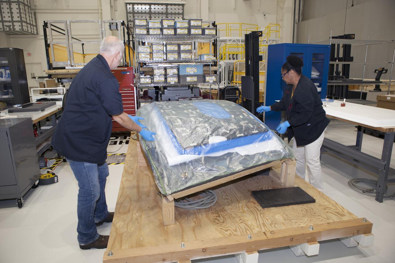
CAPE CANAVERAL, Fla. – Inside the Operations and Checkout Building high bay at NASA’s Kennedy Space Center in Florida, two tile technicians wrap a section of the thermal protection system tiles that will be installed on the Orion crew module. Orion is the exploration spacecraft designed to carry astronauts to destinations not yet explored by humans, including an asteroid and Mars. It will have emergency abort capability, sustain the crew during space travel and provide safe re-entry from deep space return velocities. The first unpiloted test flight of the Orion is scheduled to launch in 2014 atop a Delta IV rocket and in 2017 on NASA’s Space Launch System rocket. For more information, visit http://www.nasa.gov/orion. Photo credit: NASA/Dimitri Gerondidakis
CAPE CANAVERAL, Fla. – Inside the Operations and Checkout Building high bay at NASA’s Kennedy Space Center in Florida, a tile technician places spacers between the thermal protection system tiles that will be installed on the Orion crew module. Orion is the exploration spacecraft designed to carry astronauts to destinations not yet explored by humans, including an asteroid and Mars. It will have emergency abort capability, sustain the crew during space travel and provide safe re-entry from deep space return velocities. The first unpiloted test flight of the Orion is scheduled to launch in 2014 atop a Delta IV rocket and in 2017 on NASA’s Space Launch System rocket. For more information, visit http://www.nasa.gov/orion. Photo credit: NASA/Dimitri Gerondidakis
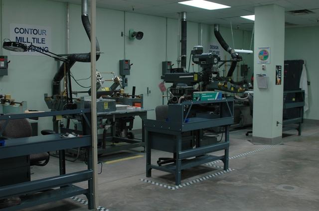
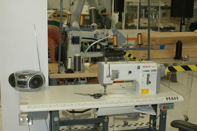
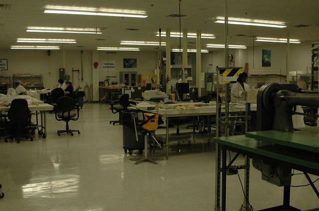
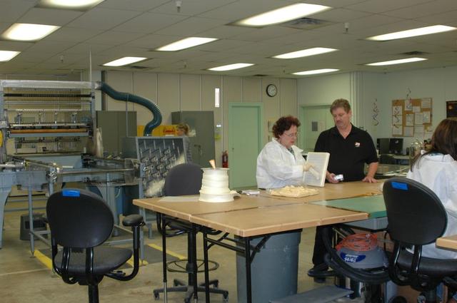
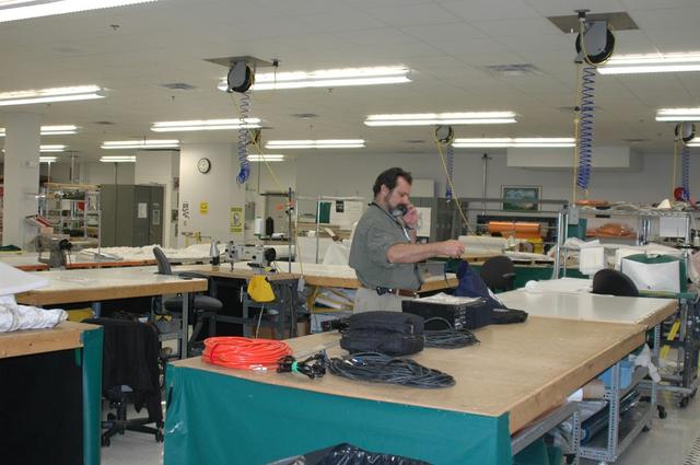
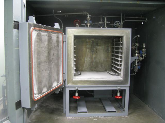
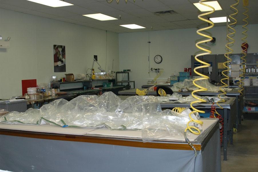
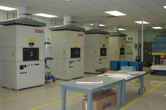
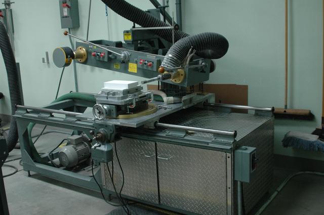
Interior view of the Thermal Ptroctection System facility
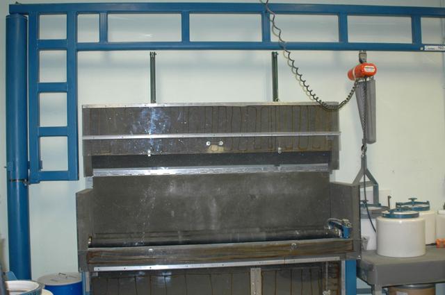
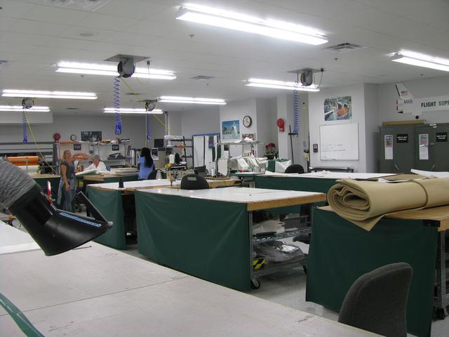
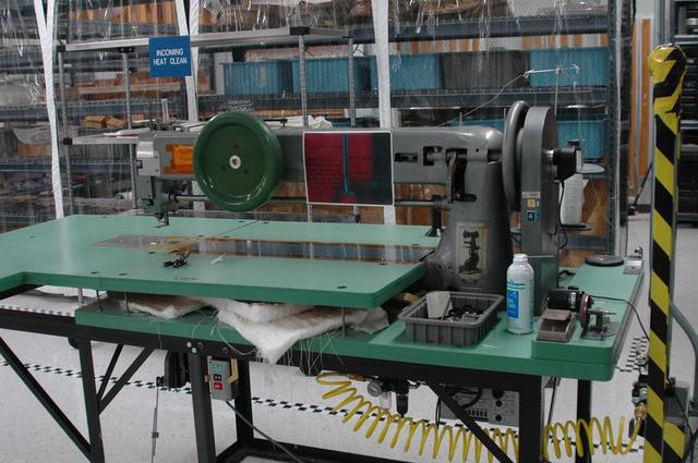
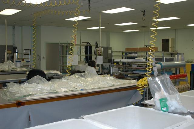
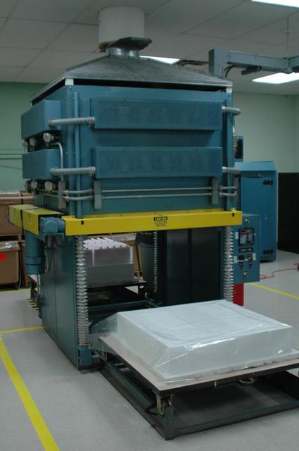
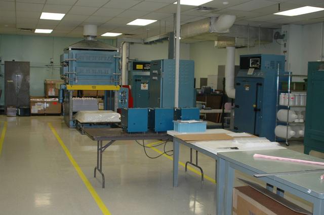
Interior view of the Thermal Ptroctection System facility
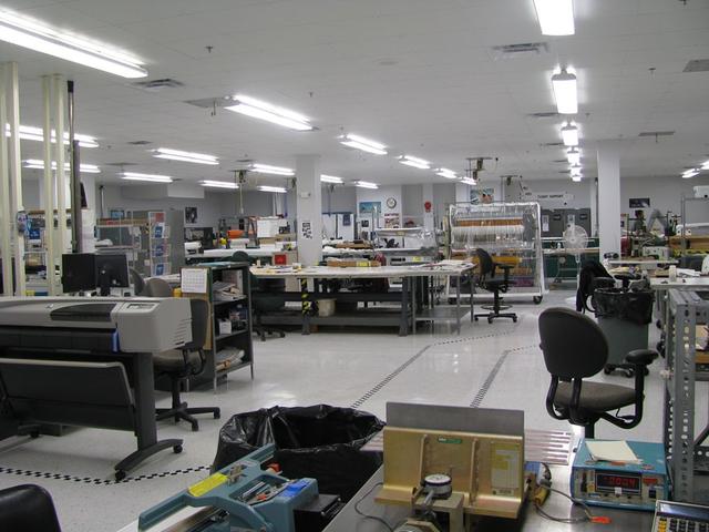
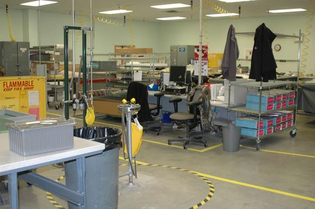
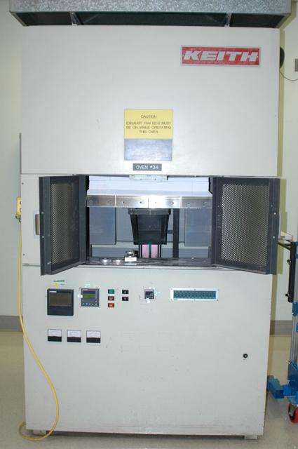
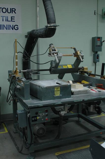
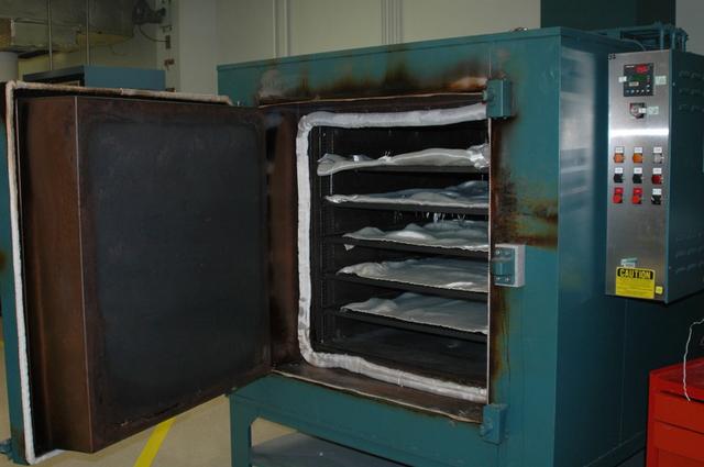
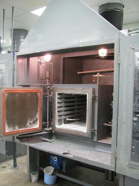
Interior view of the Thermal Ptroctection System facility
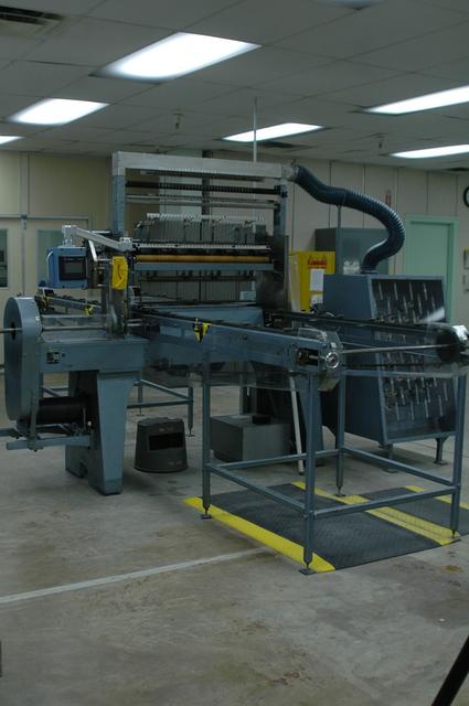
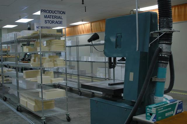
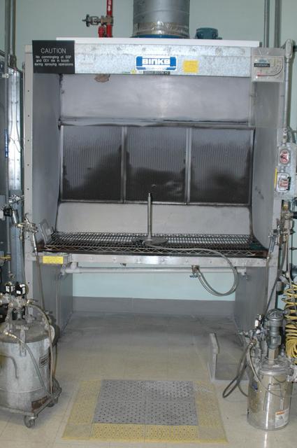
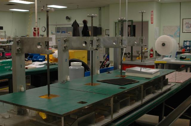
Interior view of the Thermal Ptroctection System facility
Interior view of the Thermal Ptroctection System facility
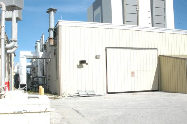
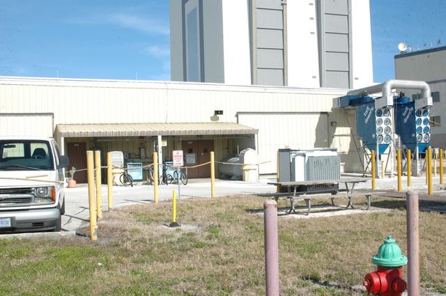
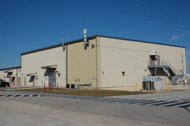
Exterior view of the Thermal Ptroctection System facility
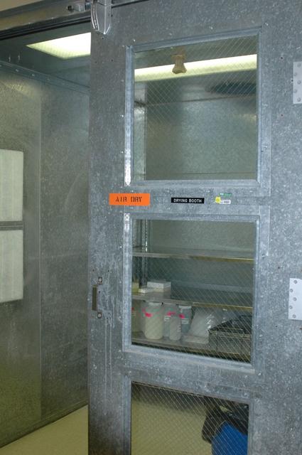
Interior view of the Thermal Ptroctection System facility
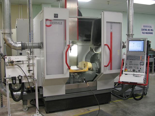
Interior view of the Thermal Ptroctection System facility
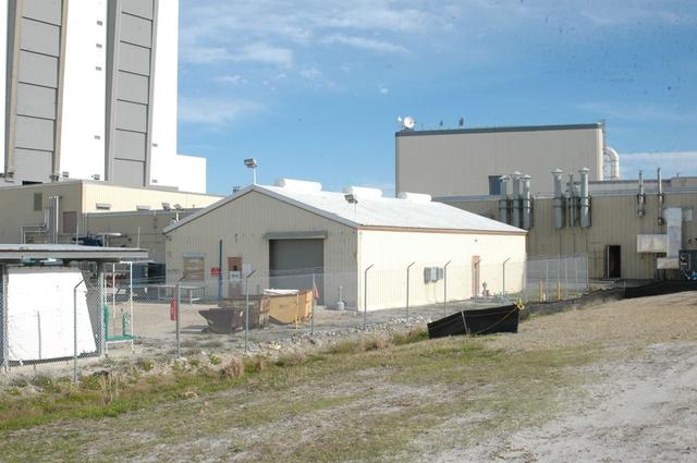
Exterior view of the Thermal Ptroctection System facility
Interior view of the Thermal Ptroctection System facility

Interior view of the Thermal Ptroctection System facility
Interior view of the Thermal Ptroctection System facility
Interior view of the Thermal Ptroctection System facility
Interior view of the Thermal Ptroctection System facility
Interior view of the Thermal Ptroctection System facility
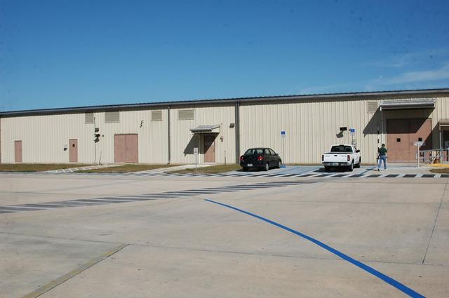
Exterior view of the Thermal Ptroctection System facility
Interior view of the Thermal Ptroctection System facility
Exterior view of the Thermal Ptroctection System facility
Interior view of the Thermal Ptroctection System facility
Interior view of the Thermal Ptroctection System facility
Interior view of the Thermal Ptroctection System facility
Interior view of the Thermal Ptroctection System facility

Interior view of the Thermal Ptroctection System facility
Interior view of the Thermal Ptroctection System facility
Interior view of the Thermal Ptroctection System facility
Interior view of the Thermal Ptroctection System facility
Interior view of the Thermal Ptroctection System facility
Interior view of the Thermal Ptroctection System facility
Interior view of the Thermal Ptroctection System facility
Interior view of the Thermal Ptroctection System facility
Exterior view of the Thermal Ptroctection System facility
Interior view of the Thermal Ptroctection System facility
Interior view of the Thermal Ptroctection System facility
Interior view of the Thermal Ptroctection System facility