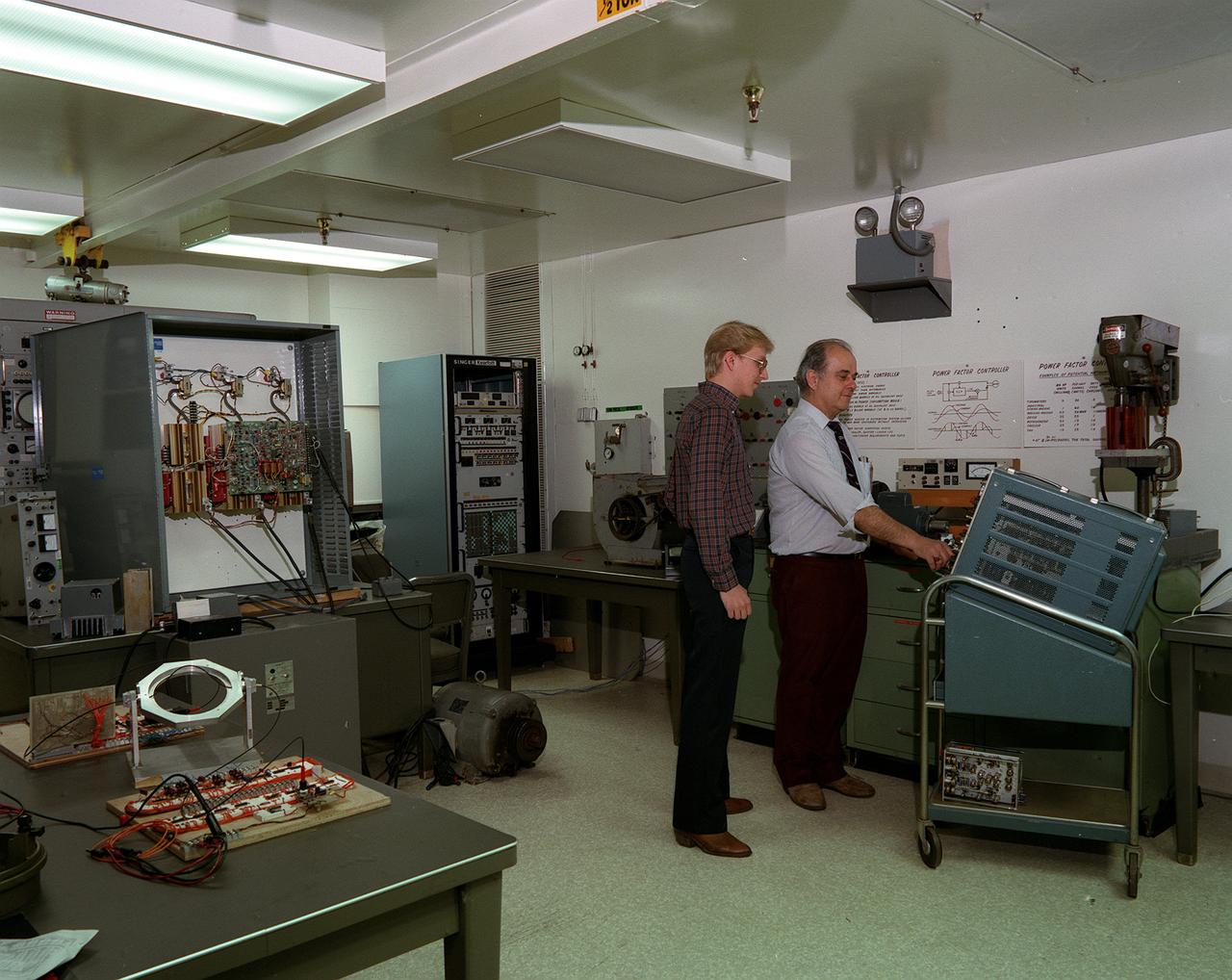
Frank Nola invented the Power Factor Controller (PFC) at Marshall Space Flight Center more than a decade ago. Nola came up with a way to curb power wastage in AC induction motors. The PFC matches voltage with the motor's actual need by continuously sensing shifts between voltage and current. When it senses a light load it cuts the voltage to the minimum needed. Potential energy savings range from 8 to 65 percent.
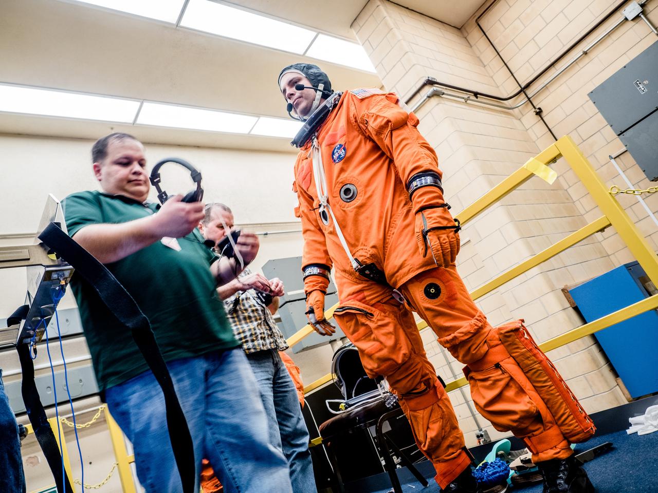
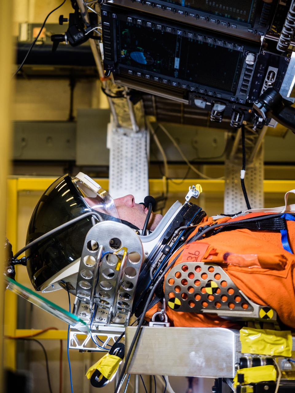
In a lab at NASA’s Johnson Space Center in Houston, engineers simulate conditions that astronauts in space suits would experience when the Orion spacecraft is vibrating during launch atop the agency’s powerful Space Launch System rocket on its way to deep space destinations on Jan. 19, 2017. A series of tests occurring this month at Johnson will help human factors engineers assess how well the crew can interact with the displays and controls they will use to monitor Orion’s systems and operate the spacecraft when necessary...Test subjects wore modified advanced crew escape suits that are being developed for astronauts in Orion, and sat in the latest design of the seat atop the crew impact attenuation system. This was the first time this key hardware was brought together to evaluate how launch vibrations may impact the astronaut’s ability to view the displays and controls.
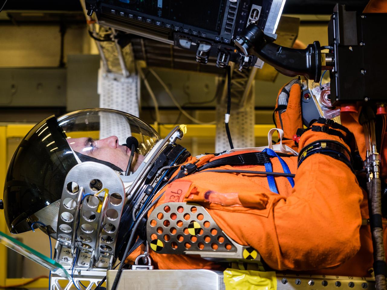
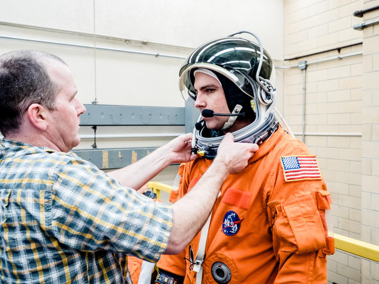
In a lab at NASA’s Johnson Space Center in Houston, engineers simulate conditions that astronauts in space suits would experience when the Orion spacecraft is vibrating during launch atop the agency’s powerful Space Launch System rocket on its way to deep space destinations on Jan. 19, 2017. A series of tests occurring this month at Johnson will help human factors engineers assess how well the crew can interact with the displays and controls they will use to monitor Orion’s systems and operate the spacecraft when necessary...Test subjects wore modified advanced crew escape suits that are being developed for astronauts in Orion, and sat in the latest design of the seat atop the crew impact attenuation system. This was the first time this key hardware was brought together to evaluate how launch vibrations may impact the astronaut’s ability to view the displays and controls.
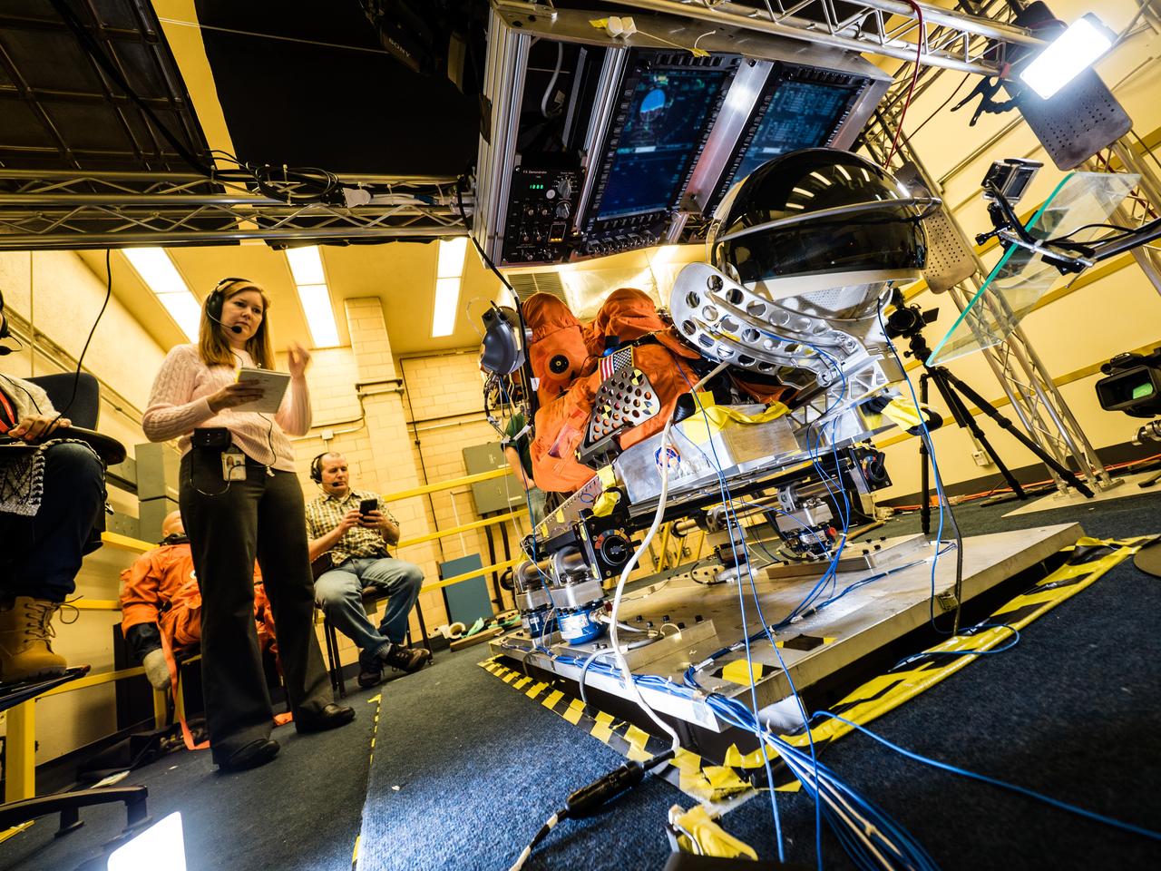
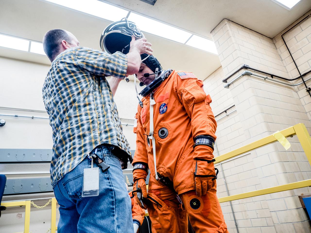
In a lab at NASA’s Johnson Space Center in Houston, engineers simulate conditions that astronauts in space suits would experience when the Orion spacecraft is vibrating during launch atop the agency’s powerful Space Launch System rocket on its way to deep space destinations on Jan. 19, 2017. A series of tests occurring this month at Johnson will help human factors engineers assess how well the crew can interact with the displays and controls they will use to monitor Orion’s systems and operate the spacecraft when necessary...Test subjects wore modified advanced crew escape suits that are being developed for astronauts in Orion, and sat in the latest design of the seat atop the crew impact attenuation system. This was the first time this key hardware was brought together to evaluate how launch vibrations may impact the astronaut’s ability to view the displays and controls.

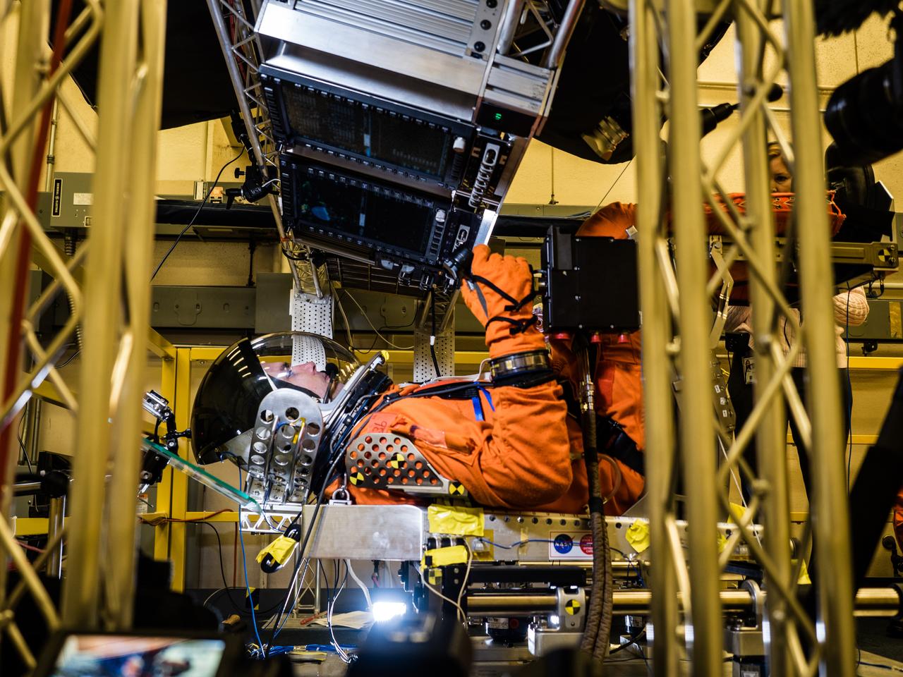
In a lab at NASA’s Johnson Space Center in Houston, engineers simulate conditions that astronauts in space suits would experience when the Orion spacecraft is vibrating during launch atop the agency’s powerful Space Launch System rocket on its way to deep space destinations on Jan. 19, 2017. A series of tests occurring this month at Johnson will help human factors engineers assess how well the crew can interact with the displays and controls they will use to monitor Orion’s systems and operate the spacecraft when necessary...Test subjects wore modified advanced crew escape suits that are being developed for astronauts in Orion, and sat in the latest design of the seat atop the crew impact attenuation system. This was the first time this key hardware was brought together to evaluate how launch vibrations may impact the astronaut’s ability to view the displays and controls.
In a lab at NASA’s Johnson Space Center in Houston, engineers simulate conditions that astronauts in space suits would experience when the Orion spacecraft is vibrating during launch atop the agency’s powerful Space Launch System rocket on its way to deep space destinations on Jan. 19, 2017. A series of tests occurring this month at Johnson will help human factors engineers assess how well the crew can interact with the displays and controls they will use to monitor Orion’s systems and operate the spacecraft when necessary...Test subjects wore modified advanced crew escape suits that are being developed for astronauts in Orion, and sat in the latest design of the seat atop the crew impact attenuation system. This was the first time this key hardware was brought together to evaluate how launch vibrations may impact the astronaut’s ability to view the displays and controls.
In a lab at NASA’s Johnson Space Center in Houston, engineers simulate conditions that astronauts in space suits would experience when the Orion spacecraft is vibrating during launch atop the agency’s powerful Space Launch System rocket on its way to deep space destinations on Jan. 19, 2017. A series of tests occurring this month at Johnson will help human factors engineers assess how well the crew can interact with the displays and controls they will use to monitor Orion’s systems and operate the spacecraft when necessary...Test subjects wore modified advanced crew escape suits that are being developed for astronauts in Orion, and sat in the latest design of the seat atop the crew impact attenuation system. This was the first time this key hardware was brought together to evaluate how launch vibrations may impact the astronaut’s ability to view the displays and controls.

In a lab at NASA’s Johnson Space Center in Houston, engineers simulate conditions that astronauts in space suits would experience when the Orion spacecraft is vibrating during launch atop the agency’s powerful Space Launch System rocket on its way to deep space destinations on Jan. 19, 2017. A series of tests occurring this month at Johnson will help human factors engineers assess how well the crew can interact with the displays and controls they will use to monitor Orion’s systems and operate the spacecraft when necessary...Test subjects wore modified advanced crew escape suits that are being developed for astronauts in Orion, and sat in the latest design of the seat atop the crew impact attenuation system. This was the first time this key hardware was brought together to evaluate how launch vibrations may impact the astronaut’s ability to view the displays and controls.
In a lab at NASA’s Johnson Space Center in Houston, engineers simulate conditions that astronauts in space suits would experience when the Orion spacecraft is vibrating during launch atop the agency’s powerful Space Launch System rocket on its way to deep space destinations on Jan. 19, 2017. A series of tests occurring this month at Johnson will help human factors engineers assess how well the crew can interact with the displays and controls they will use to monitor Orion’s systems and operate the spacecraft when necessary...Test subjects wore modified advanced crew escape suits that are being developed for astronauts in Orion, and sat in the latest design of the seat atop the crew impact attenuation system. This was the first time this key hardware was brought together to evaluate how launch vibrations may impact the astronaut’s ability to view the displays and controls.

In a lab at NASA’s Johnson Space Center in Houston, engineers simulate conditions that astronauts in space suits would experience when the Orion spacecraft is vibrating during launch atop the agency’s powerful Space Launch System rocket on its way to deep space destinations on Jan. 19, 2017. A series of tests occurring this month at Johnson will help human factors engineers assess how well the crew can interact with the displays and controls they will use to monitor Orion’s systems and operate the spacecraft when necessary...Test subjects wore modified advanced crew escape suits that are being developed for astronauts in Orion, and sat in the latest design of the seat atop the crew impact attenuation system. This was the first time this key hardware was brought together to evaluate how launch vibrations may impact the astronaut’s ability to view the displays and controls.
In a lab at NASA’s Johnson Space Center in Houston, engineers simulate conditions that astronauts in space suits would experience when the Orion spacecraft is vibrating during launch atop the agency’s powerful Space Launch System rocket on its way to deep space destinations on Jan. 19, 2017. A series of tests occurring this month at Johnson will help human factors engineers assess how well the crew can interact with the displays and controls they will use to monitor Orion’s systems and operate the spacecraft when necessary...Test subjects wore modified advanced crew escape suits that are being developed for astronauts in Orion, and sat in the latest design of the seat atop the crew impact attenuation system. This was the first time this key hardware was brought together to evaluate how launch vibrations may impact the astronaut’s ability to view the displays and controls.
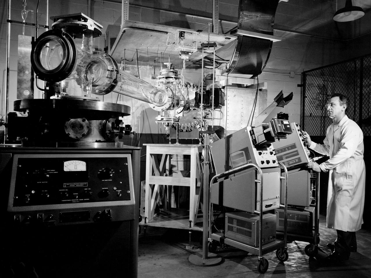
Researcher Charles Michels operates a coaxial plasma gun rig in Cell SW-13 of the Engine Research Building at the National Aeronautics and Space Administration (NASA) Lewis Research Center. From 1962 to 1967 NASA Lewis investigated coaxial plasma guns powered by conventional capacitor banks. The studies were part of a larger effort to identify electromagnetic accelerators for space propulsion. NASA worked with General Dynamics, General Electric, General Motors, and Republic Aviation on the project. NASA Lewis conducted a research program to determine which factors influenced the coaxial gun’s efficiency and analyze the acceleration process. The system had not previously been used for propulsion applications. The single-shot gun’s fast gas valve and capacitor banks with variable-delay ignition source permitted the evaluation of gun performance under controllable propellant quantity and distribution conditions. The coaxial plasma gun was the most basic type of electromagnetic accelerator. It included a charged capacitor in series with a pair of coaxial electrodes. An electrical breakdown occurred when gas was admitted to the inter-electrode region. The gas instantly became a good conductor and formed a conducting sheet that separated the magnetic field from the open region beyond. The highly-conducting gas was basically expelled by the force of the magnetic pressure. This type of thruster could operate at the high instantaneous power levels without decreasing its average power level.
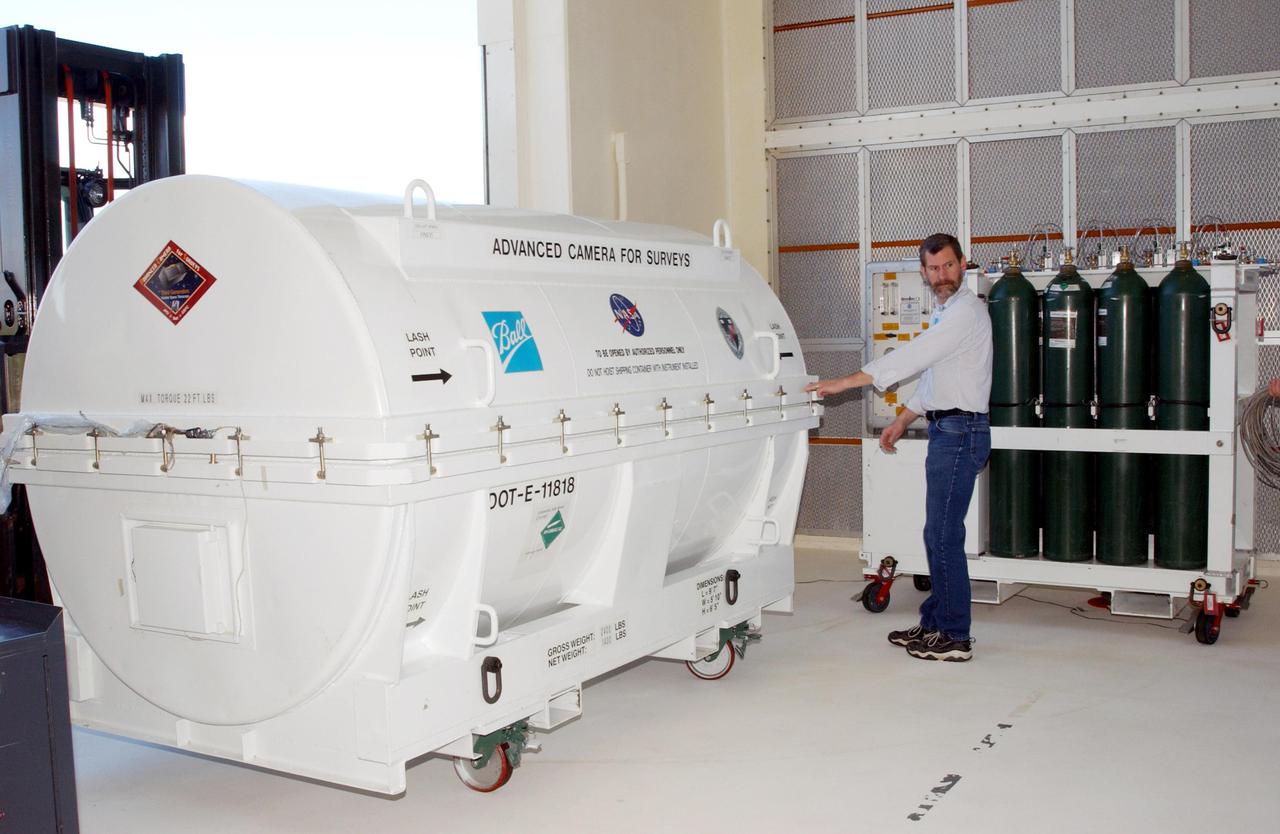
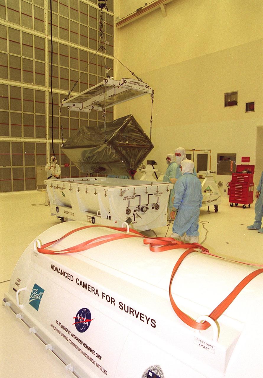
KENNEDY SPACE CENTER, Fla. -- A piece of equipment for Hubble Space Telescope Servicing mission is moved inside Hangar AE, Cape Canaveral. In the canister is the Advanced Camera for Surveys (ACS). The ACS will increase the discovery efficiency of the HST by a factor of ten. It consists of three electronic cameras and a complement of filters and dispersers that detect light from the ultraviolet to the near infrared (1200 - 10,000 angstroms). The ACS was built through a collaborative effort between Johns Hopkins University, Goddard Space Flight Center, Ball Aerospace Corporation and Space Telescope Science Institute. The goal of the mission, STS-109, is to service the HST, replacing Solar Array 2 with Solar Array 3, replacing the Power Control Unit, removing the Faint Object Camera and installing the ACS, installing the Near Infrared Camera and Multi-Object Spectrometer (NICMOS) Cooling System, and installing New Outer Blanket Layer insulation on bays 5 through 8. Mission STS-109 is scheduled for launch Feb. 14, 2002
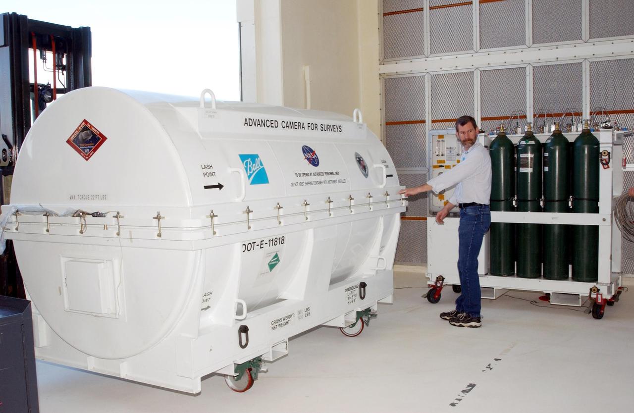
KENNEDY SPACE CENTER, Fla. -- A piece of equipment for Hubble Space Telescope Servicing mission is moved inside Hangar AE, Cape Canaveral. In the canister is the Advanced Camera for Surveys (ACS). The ACS will increase the discovery efficiency of the HST by a factor of ten. It consists of three electronic cameras and a complement of filters and dispersers that detect light from the ultraviolet to the near infrared (1200 - 10,000 angstroms). The ACS was built through a collaborative effort between Johns Hopkins University, Goddard Space Flight Center, Ball Aerospace Corporation and Space Telescope Science Institute. The goal of the mission, STS-109, is to service the HST, replacing Solar Array 2 with Solar Array 3, replacing the Power Control Unit, removing the Faint Object Camera and installing the ACS, installing the Near Infrared Camera and Multi-Object Spectrometer (NICMOS) Cooling System, and installing New Outer Blanket Layer insulation on bays 5 through 8. Mission STS-109 is scheduled for launch Feb. 14, 2002
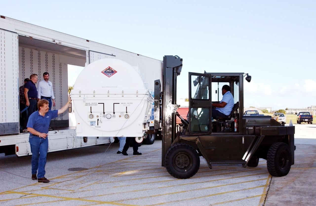
KENNEDY SPACE CENTER, Fla. - A piece of equipment for Hubble Space Telescope Servicing mission arrives at Hangar AE, Cape Canaveral. Inside the canister is the Advanced Camera for Surveys (ACS). The ACS will increase the discovery efficiency of the HST by a factor of ten. It consists of three electronic cameras and a complement of filters and dispersers that detect light from the ultraviolet to the near infrared (1200 - 10,000 angstroms). The ACS was built through a collaborative effort between Johns Hopkins University, Goddard Space Flight Center, Ball Aerospace Corporation and Space Telescope Science Institute. The goal of the mission, STS-109, is to service the HST, replacing Solar Array 2 with Solar Array 3, replacing the Power Control Unit, removing the Faint Object Camera and installing the ACS, installing the Near Infrared Camera and Multi-Object Spectrometer (NICMOS) Cooling System, and installing New Outer Blanket Layer insulation on bays 5 through 8. Mission STS-109 is scheduled for launch Feb. 14, 2002
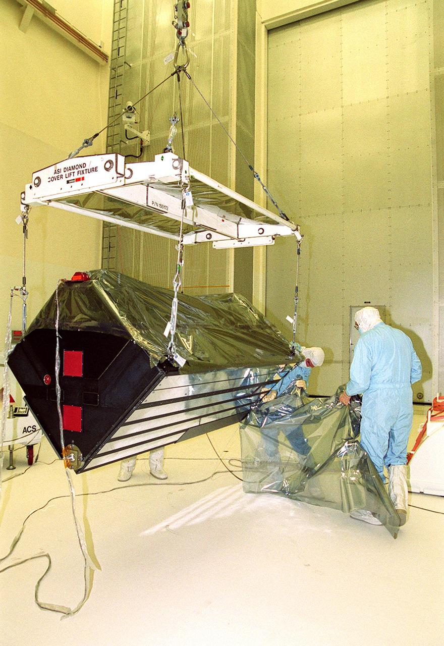
KENNEDY SPACE CENTER, Fla. -- Workers in Hangar AandE remove the wrapping from around the Advanced Camera for Surveys, which is suspended by an overhead crane. Part of the payload on the Hubble Space Telescope Servicing Mission, STS-109, the ACS will increase the discovery efficiency of the HST by a factor of ten. It consists of three electronic cameras and a complement of filters and dispersers that detect light from the ultraviolet to the near infrared (1200 - 10,000 angstroms). The ACS was built through a collaborative effort between Johns Hopkins University, Goddard Space Flight Center, Ball Aerospace Corporation and Space Telescope Science Institute. Tasks for the mission include replacing Solar Array 2 with Solar Array 3, replacing the Power Control Unit, removing the Faint Object Camera and installing the ACS, installing the Near Infrared Camera and Multi-Object Spectrometer (NICMOS) Cooling System, and installing New Outer Blanket Layer insulation on bays 5 through 8. Mission STS-109 is scheduled for launch Feb. 14, 2002
KENNEDY SPACE CENTER, Fla. -- In Hangar A&E, workers watch as an overhead crane lifts the Advanced Camera for Surveys out of its transportation container. Part of the payload on the Hubble Space Telescope Servicing Mission, STS-109, the ACS will increase the discovery efficiency of the HST by a factor of ten. It consists of three electronic cameras and a complement of filters and dispersers that detect light from the ultraviolet to the near infrared (1200 - 10,000 angstroms). The ACS was built through a collaborative effort between Johns Hopkins University, Goddard Space Flight Center, Ball Aerospace Corporation and Space Telescope Science Institute. Tasks for the mission include replacing Solar Array 2 with Solar Array 3, replacing the Power Control Unit, removing the Faint Object Camera and installing the ACS, installing the Near Infrared Camera and Multi-Object Spectrometer (NICMOS) Cooling System, and installing New Outer Blanket Layer insulation on bays 5 through 8. Mission STS-109 is scheduled for launch Feb. 14, 2002

KENNEDY SPACE CENTER, Fla. -- Fully unwrapped, the Advanced Camera for Surveys, which is suspended by an overhead crane, is checked over by workers. Part of the payload on the Hubble Space Telescope Servicing Mission, STS-109, the ACS will increase the discovery efficiency of the HST by a factor of ten. It consists of three electronic cameras and a complement of filters and dispersers that detect light from the ultraviolet to the near infrared (1200 - 10,000 angstroms). The ACS was built through a collaborative effort between Johns Hopkins University, Goddard Space Flight Center, Ball Aerospace Corporation and Space Telescope Science Institute. Tasks for the mission include replacing Solar Array 2 with Solar Array 3, replacing the Power Control Unit, removing the Faint Object Camera and installing the ACS, installing the Near Infrared Camera and Multi-Object Spectrometer (NICMOS) Cooling System, and installing New Outer Blanket Layer insulation on bays 5 through 8. Mission STS-109 is scheduled for launch Feb. 14, 2002

KENNEDY SPACE CENTER, Fla. - A piece of equipment for Hubble Space Telescope Servicing mission arrives at Hangar AE, Cape Canaveral. Inside the canister is the Advanced Camera for Surveys (ACS). The ACS will increase the discovery efficiency of the HST by a factor of ten. It consists of three electronic cameras and a complement of filters and dispersers that detect light from the ultraviolet to the near infrared (1200 - 10,000 angstroms). The ACS was built through a collaborative effort between Johns Hopkins University, Goddard Space Flight Center, Ball Aerospace Corporation and Space Telescope Science Institute. The goal of the mission, STS-109, is to service the HST, replacing Solar Array 2 with Solar Array 3, replacing the Power Control Unit, removing the Faint Object Camera and installing the ACS, installing the Near Infrared Camera and Multi-Object Spectrometer (NICMOS) Cooling System, and installing New Outer Blanket Layer insulation on bays 5 through 8. Mission STS-109 is scheduled for launch Feb. 14, 2002
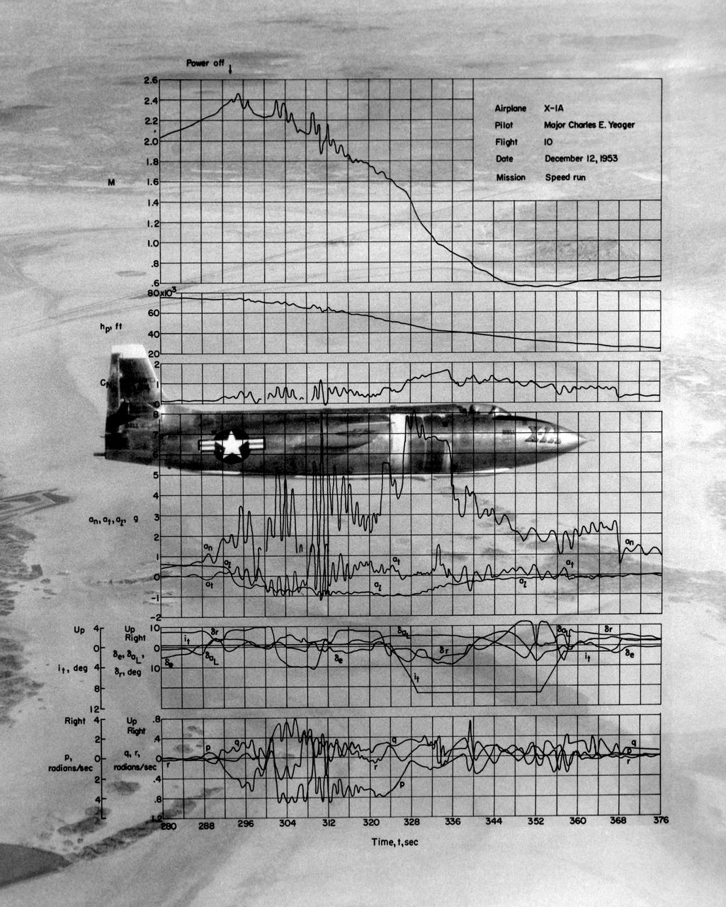
This photo of the X-1A includes graphs of the flight data from Maj. Charles E. Yeager's Mach 2.44 flight on December 12, 1953. (This was only a few days short of the 50th anniversary of the Wright brothers' first powered flight.) After reaching Mach 2.44, then the highest speed ever reached by a piloted aircraft, the X-1A tumbled completely out of control. The motions were so violent that Yeager cracked the plastic canopy with his helmet. He finally recovered from a inverted spin and landed on Rogers Dry Lakebed. Among the data shown are Mach number and altitude (the two top graphs). The speed and altitude changes due to the tumble are visible as jagged lines. The third graph from the bottom shows the G-forces on the airplane. During the tumble, these twice reached 8 Gs or 8 times the normal pull of gravity at sea level. (At these G forces, a 200-pound human would, in effect, weigh 1,600 pounds if a scale were placed under him in the direction of the force vector.) Producing these graphs was a slow, difficult process. The raw data from on-board instrumentation recorded on oscillograph film. Human computers then reduced the data and recorded it on data sheets, correcting for such factors as temperature and instrument errors. They used adding machines or slide rules for their calculations, pocket calculators being 20 years in the future.