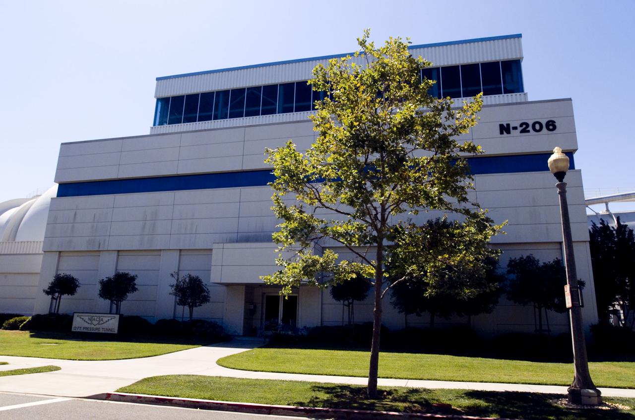
N-206 Ames 12ft Pressure Wind Tunnel
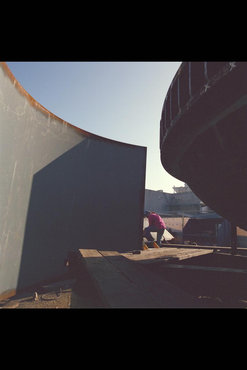
N-206 12ft Pressure Wind Tunnel reconstruction
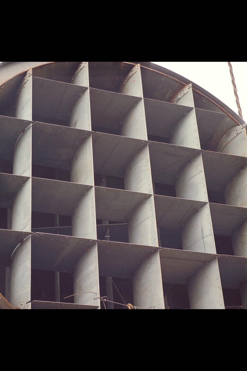
N-206 12ft Pressure Wind Tunnel reconstruction - settling chamber lift
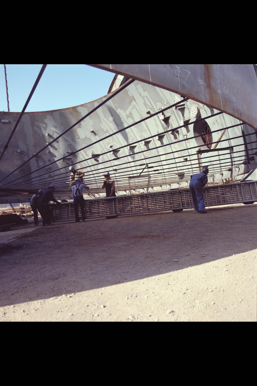
N-206 12ft. Pressure Wind Tunnel reconstruction - installation of vanes
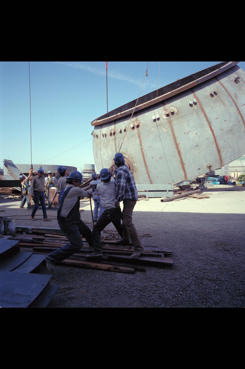
N-206 12ft Pressure Wind Tunnel reconstruction - settling chamber lift
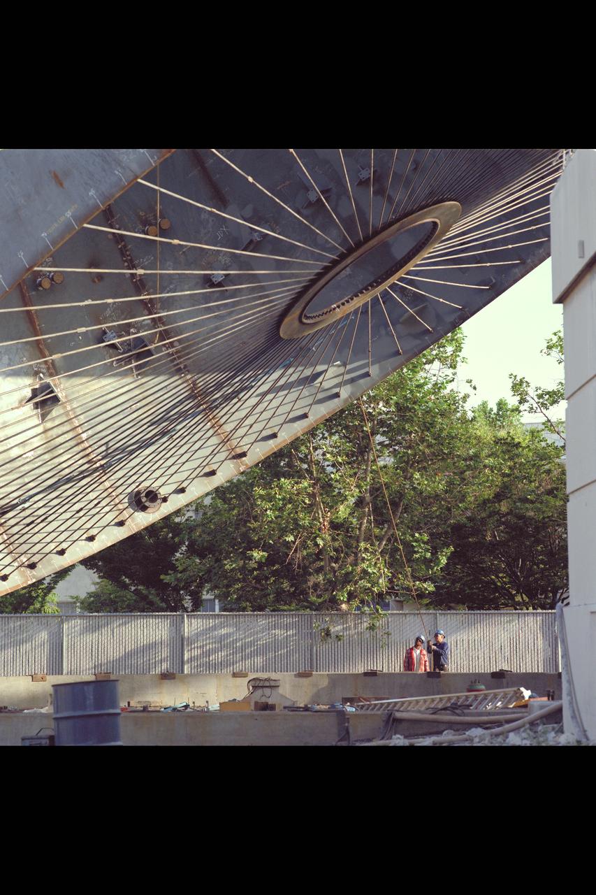
N-206 pressure Wind Tunnel Reconstruction: settling chamber lift

N-206 12ft pressure wind tunnel reconstruction, welding and assembly of rings
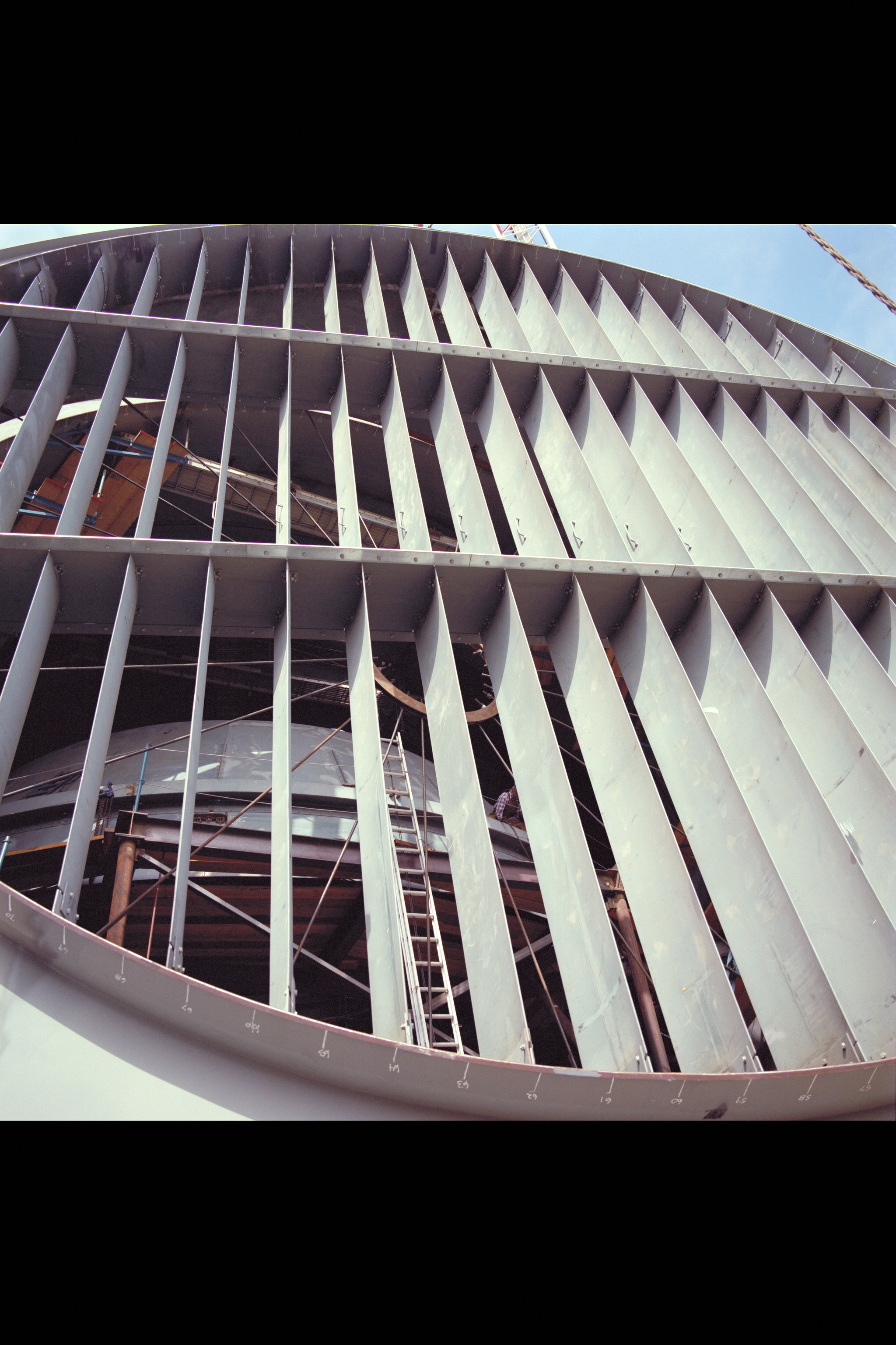
N-206 12ft Pressure Wind Tunnel reconstruction - installation of vanes
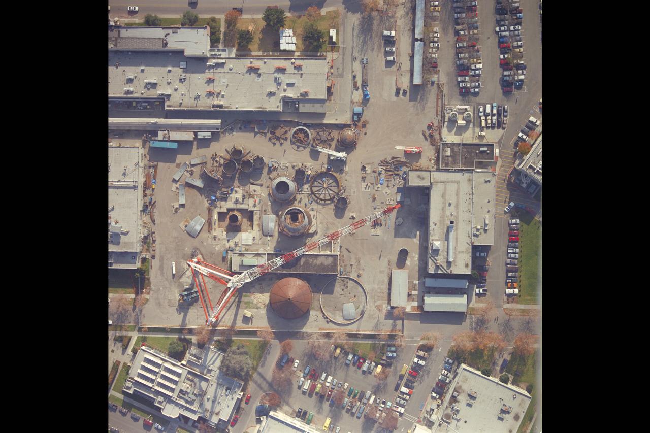
N-206 12ft Pressure Wind Tunnel reconstruction aerial with crane
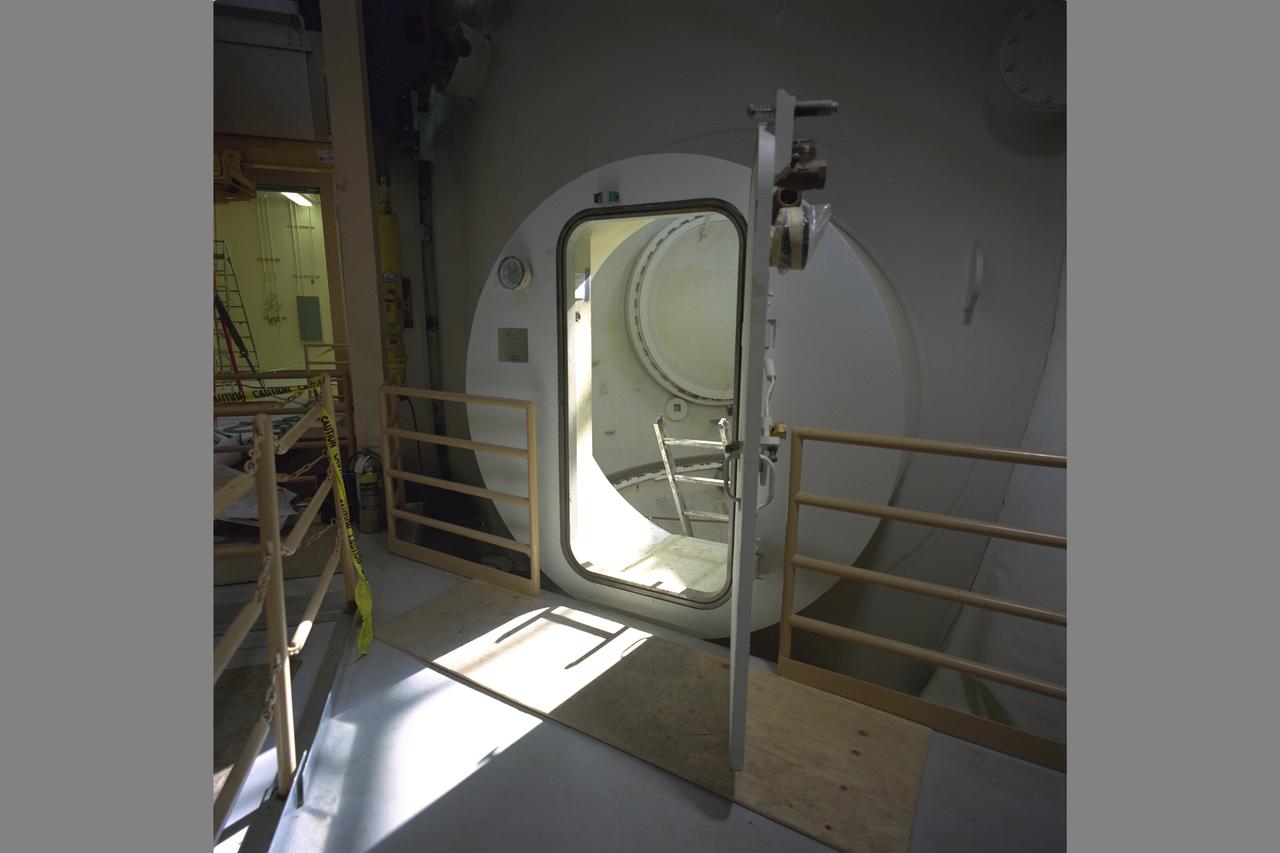
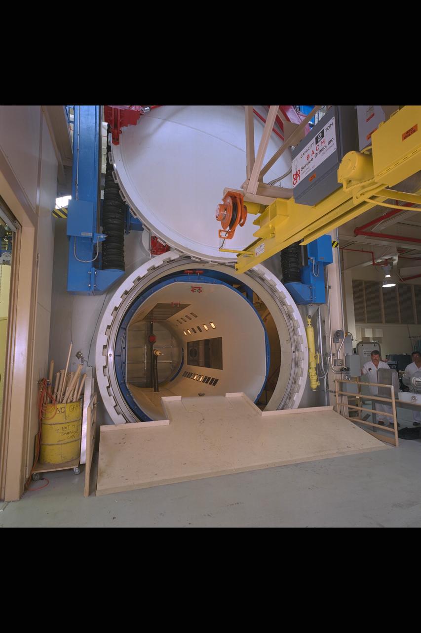
N-206 NASA Ames Research Center 12ft Pressure Wind Tunnel. reconstruction - test section door
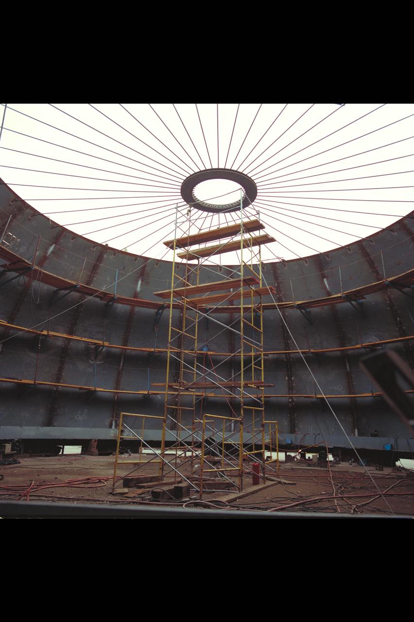
N-206 12ft Pressure Wind Tunnel reconstruction - looking out from inside of partially assembled test section
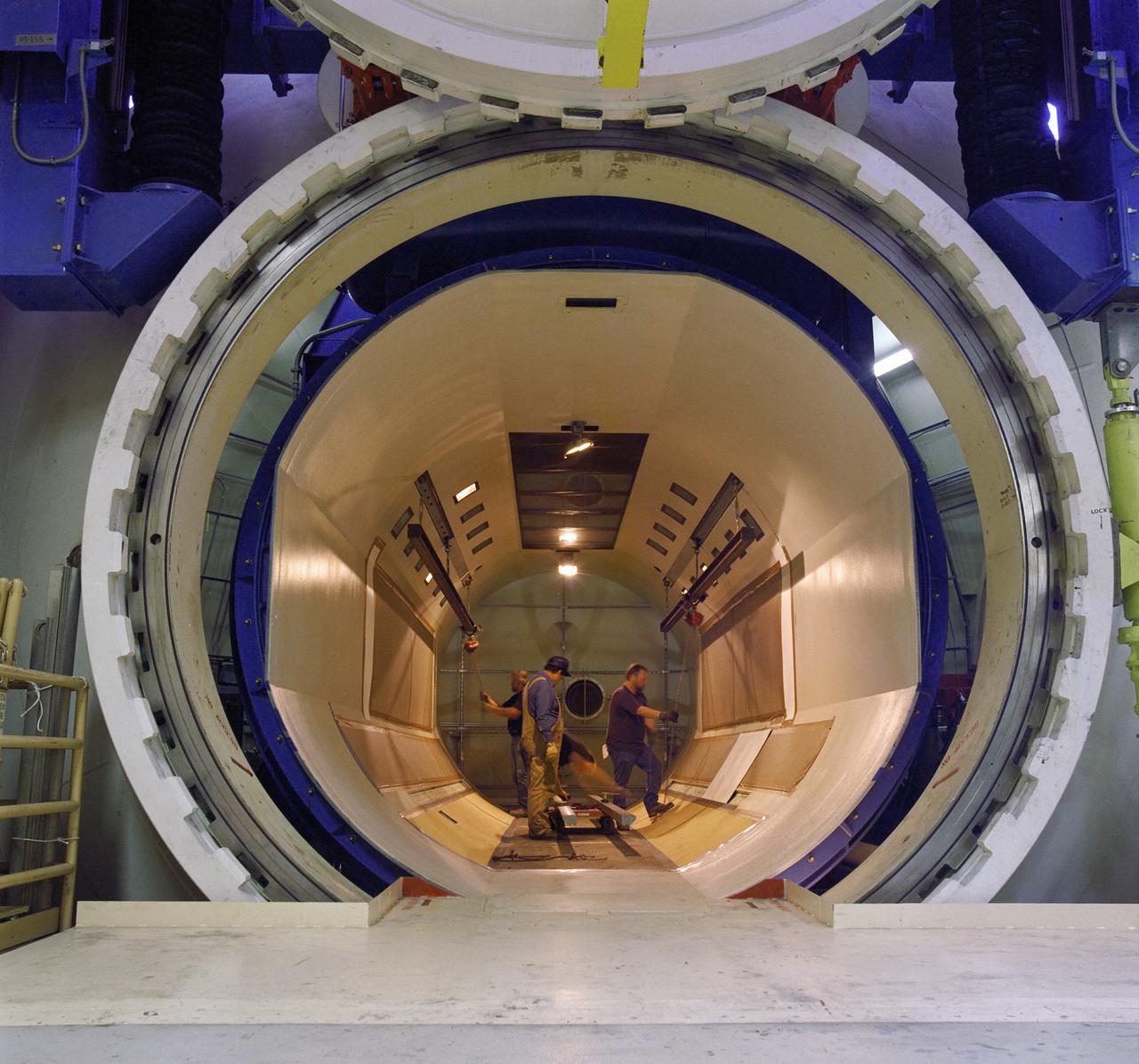
N-206 NASA Ames Research Center 12ft Pressure Wind Tunnel ADTE (Aeronautics Design & Test Environment) - test section
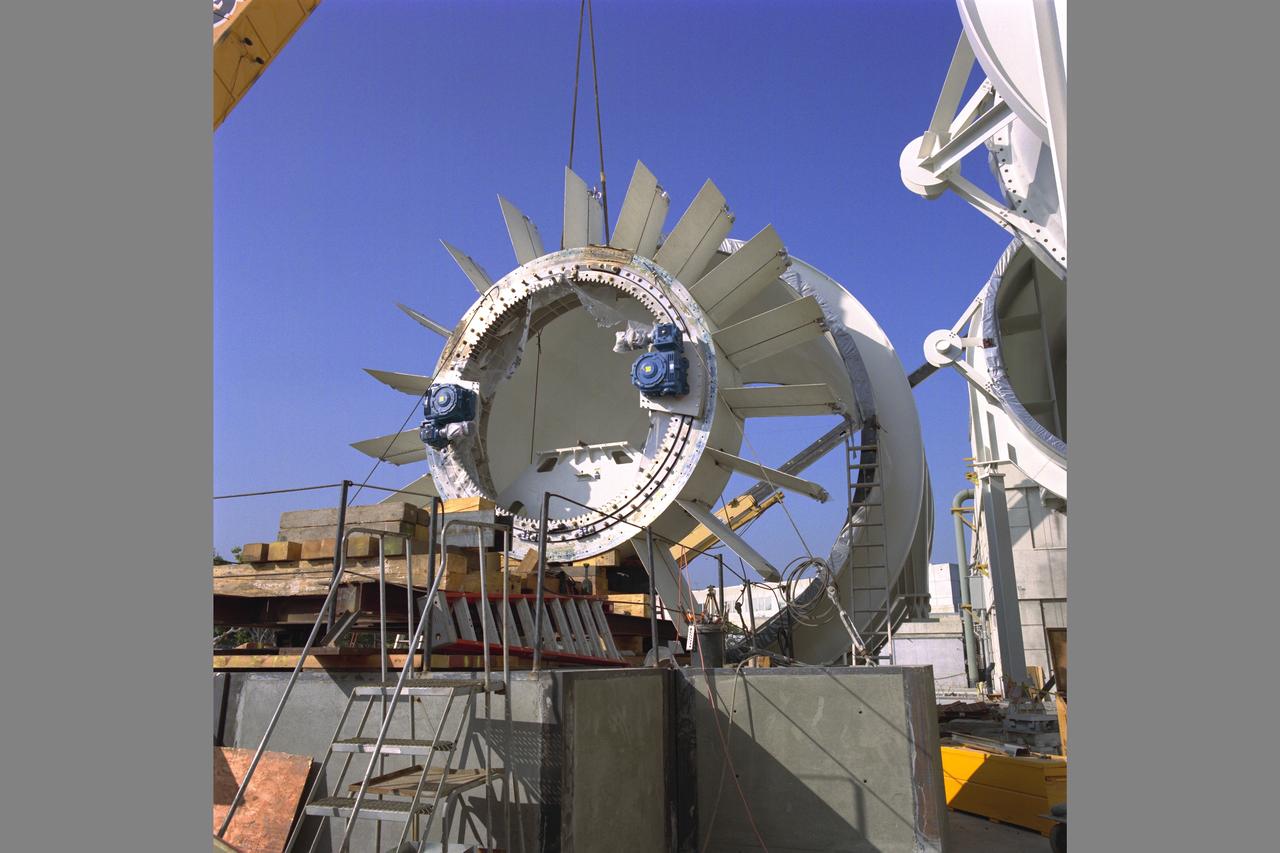
N-206 NASA Ames Research Center 12ft w.t. Pressure Wind Tunnel reconstruction - turning vanes, fan being lifted in
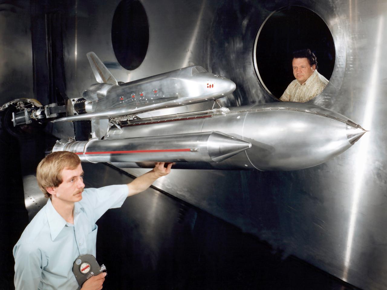
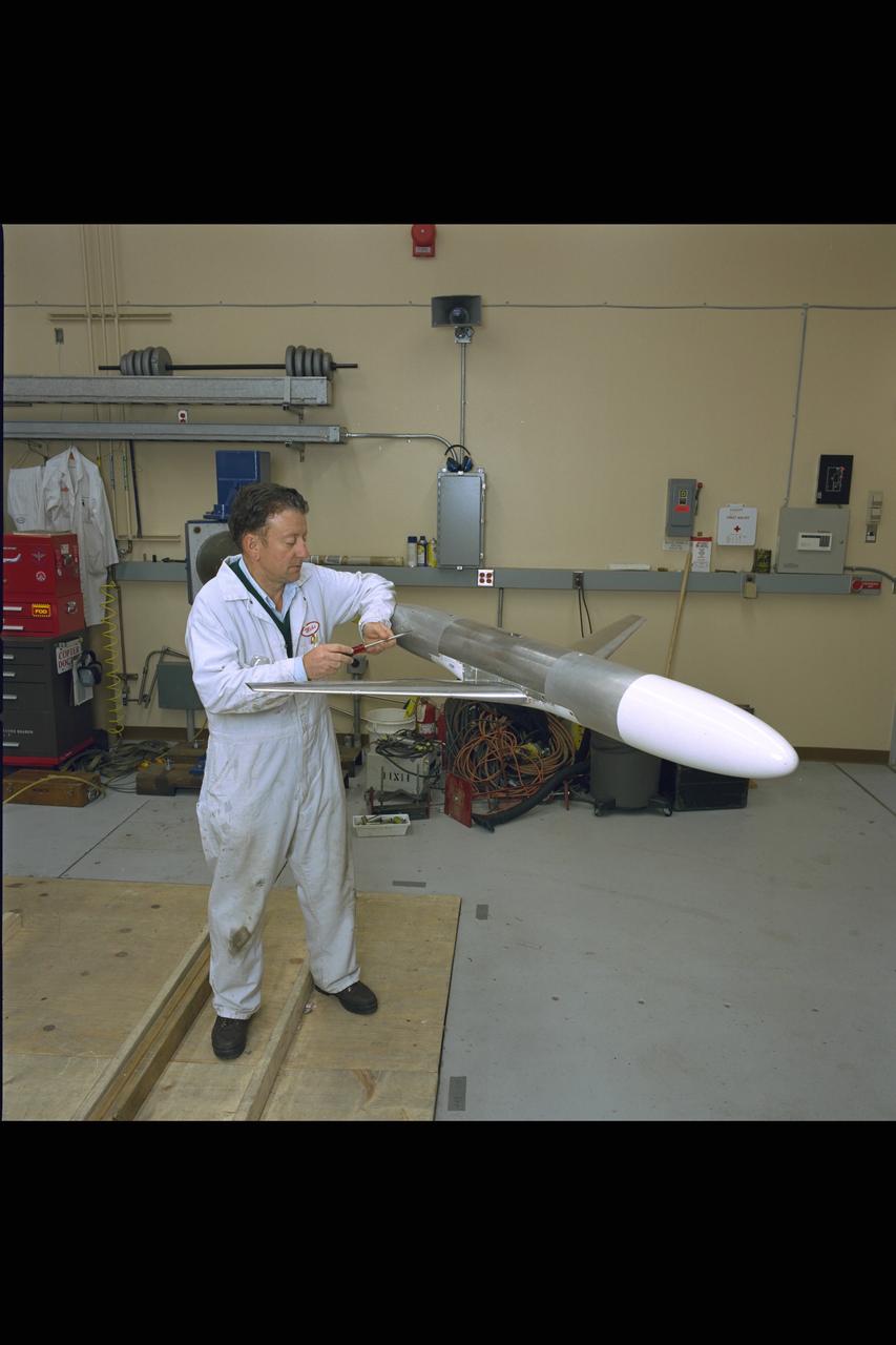
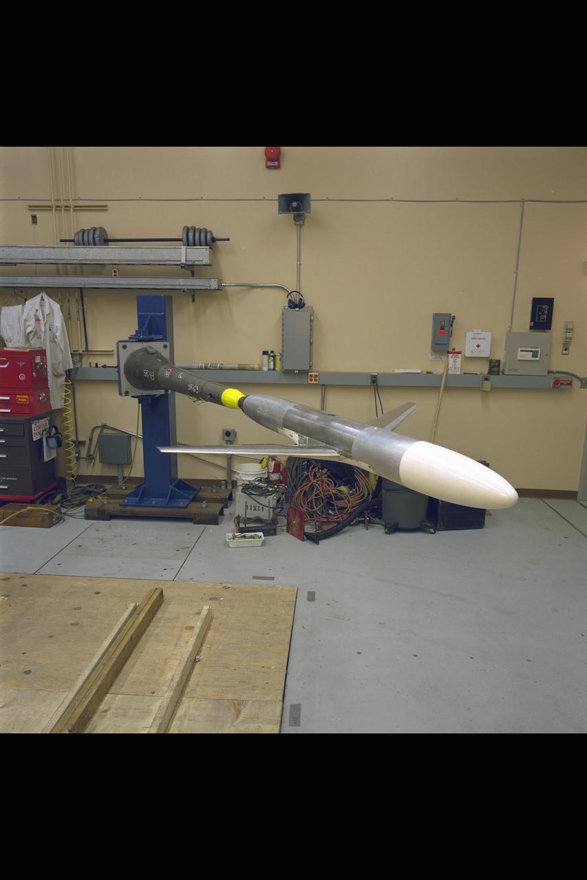
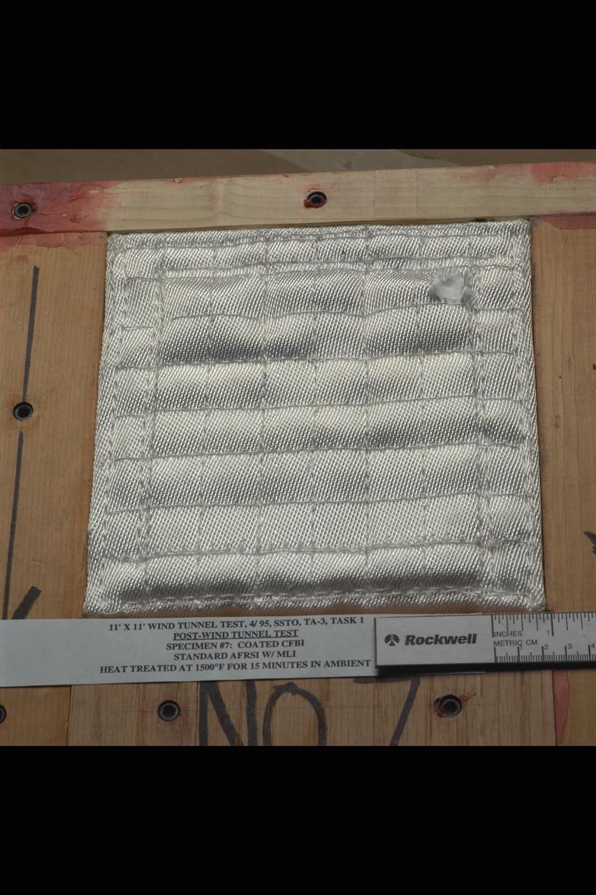
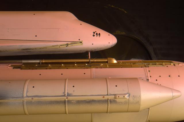
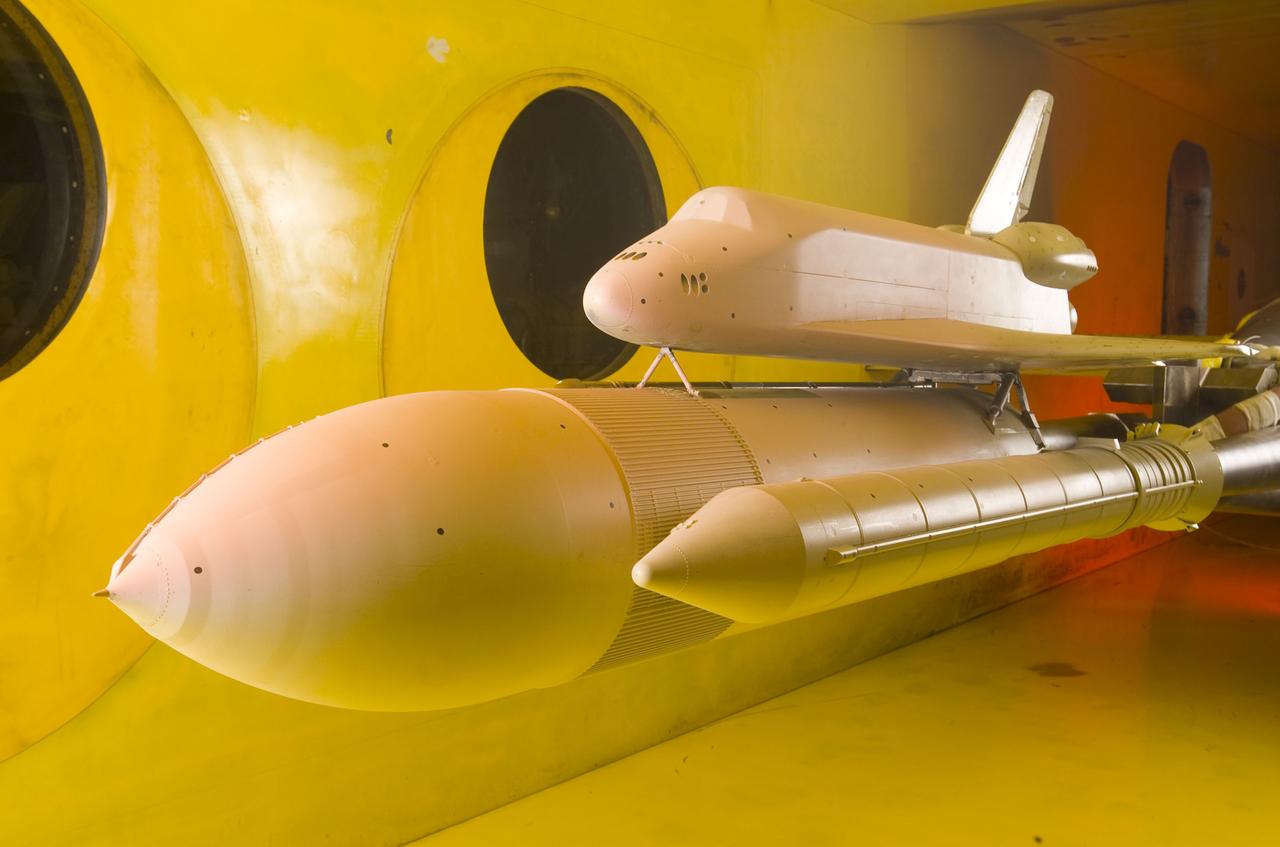
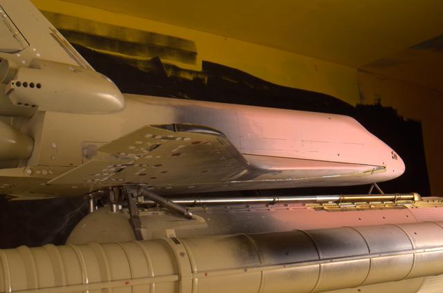
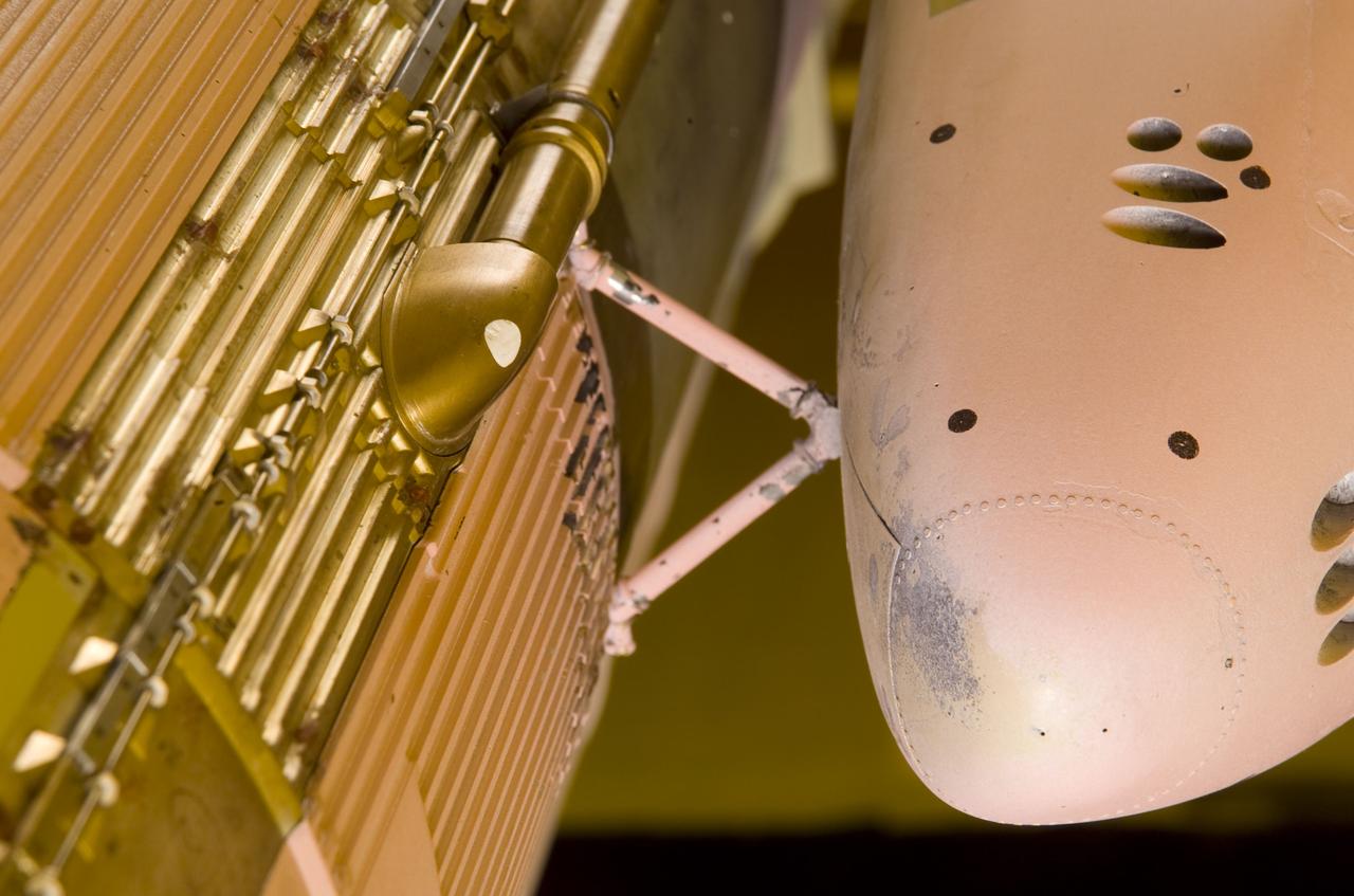
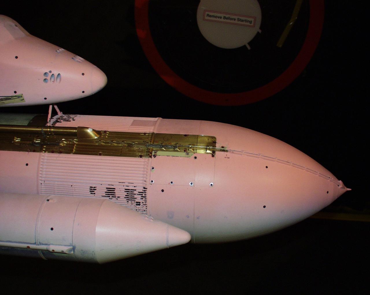
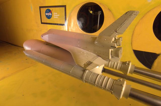
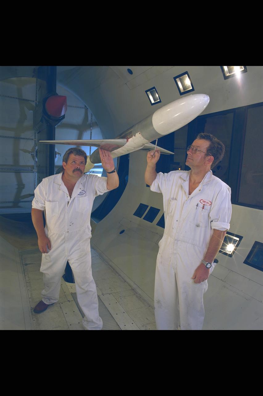
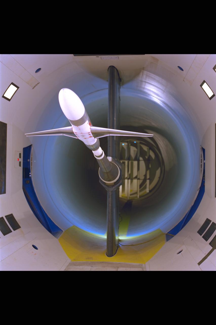
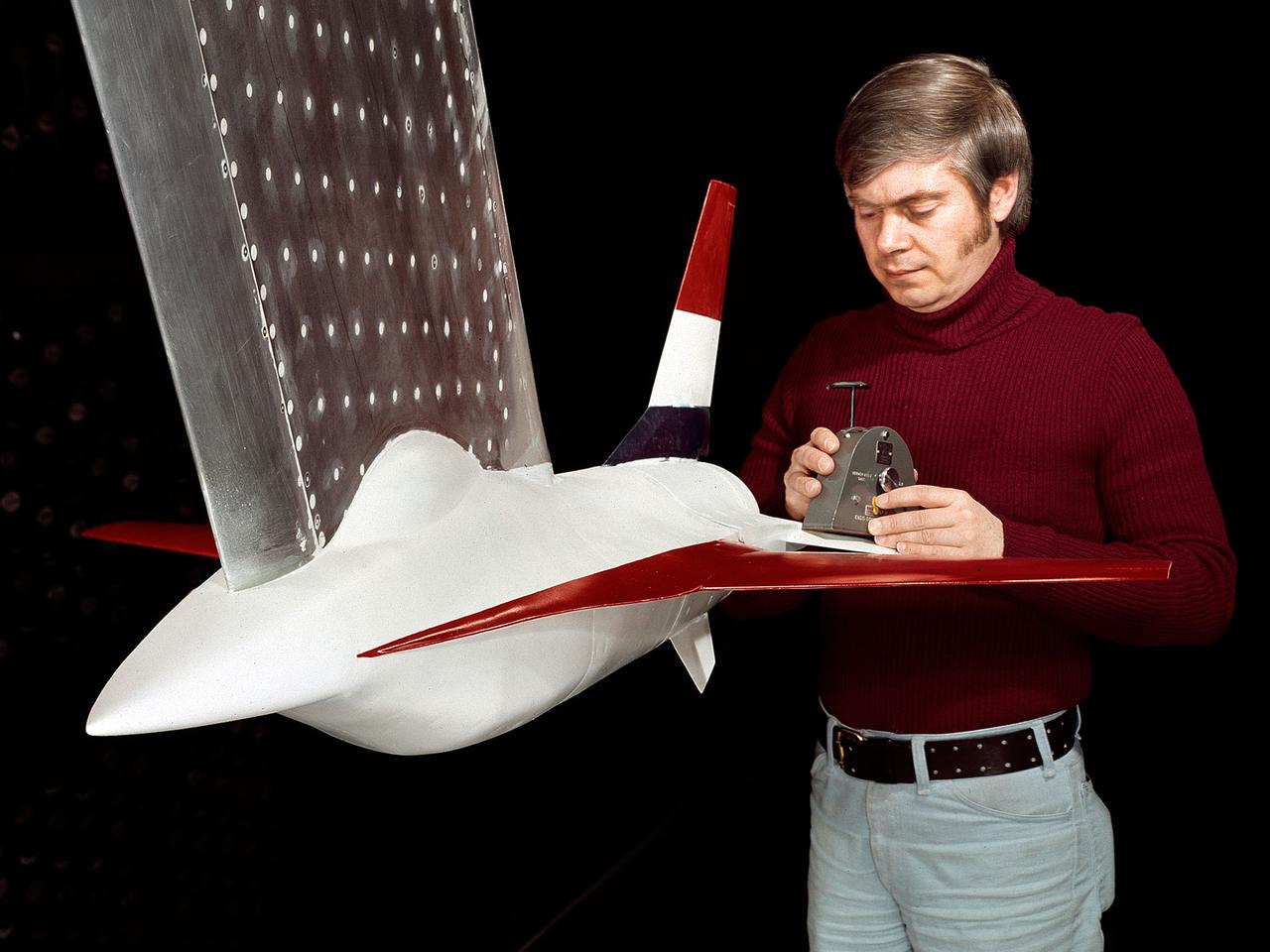
Technicians examine a scale model of the space shuttle used to obtain pressure data during tests in the 10- by 10-Foot Supersonic Wind Tunnel at the National Aeronautics and Space Administration (NASA) Lewis Research Center. Lewis researchers used the 10- by 10 tunnel extensively in the 1970s to study shuttle configurations in order to forecast conditions during an actual flight. These tests included analysis of the solid rocket boosters’ aerodynamics, orbiter forebody angle -of -attack and air speed, base heating for entire shuttle, and engine-out loads. The test seen in this photograph used a 3.5- percent scale aluminum alloy model of the entire launch configuration. The program was designed to obtain aerodynamic pressure data. The tests were part of a larger program to study possible trouble areas for the shuttle’s new Advanced Flexible Reusable Surface Insulation. The researchers obtained aeroacoustic data and pressure distributions from five locations on the model. Over 100 high-temperature pressure transducers were attached to the model. Other portions of the test program were conducted at Lewis’ 8- by 6-Foot Supersonic Wind Tunnel and the 11- by 11-Foot Transonic Wind Tunnel at Ames Research Center.
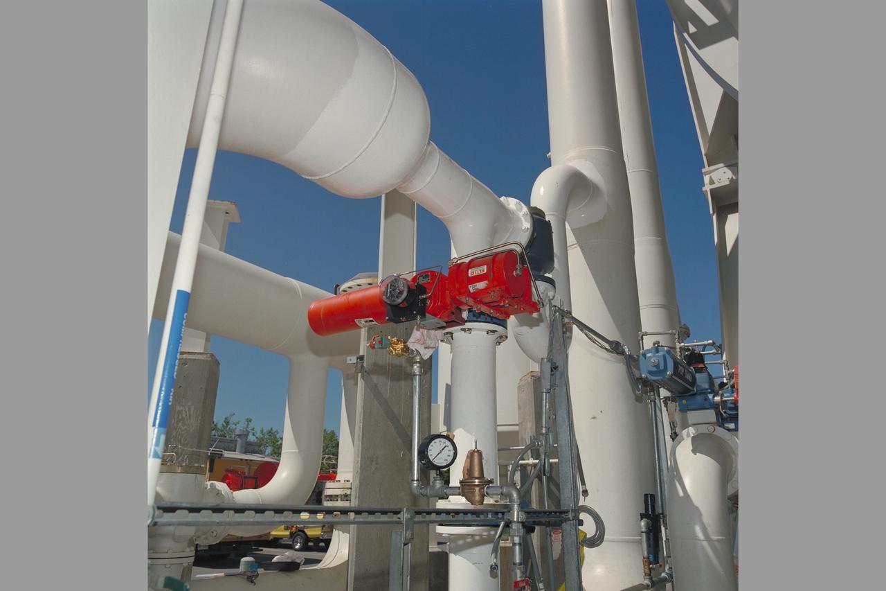
N-206 12ft W.T. ADTE Project (Aeronautics Design and Test Environment) Old TPC valve actuators
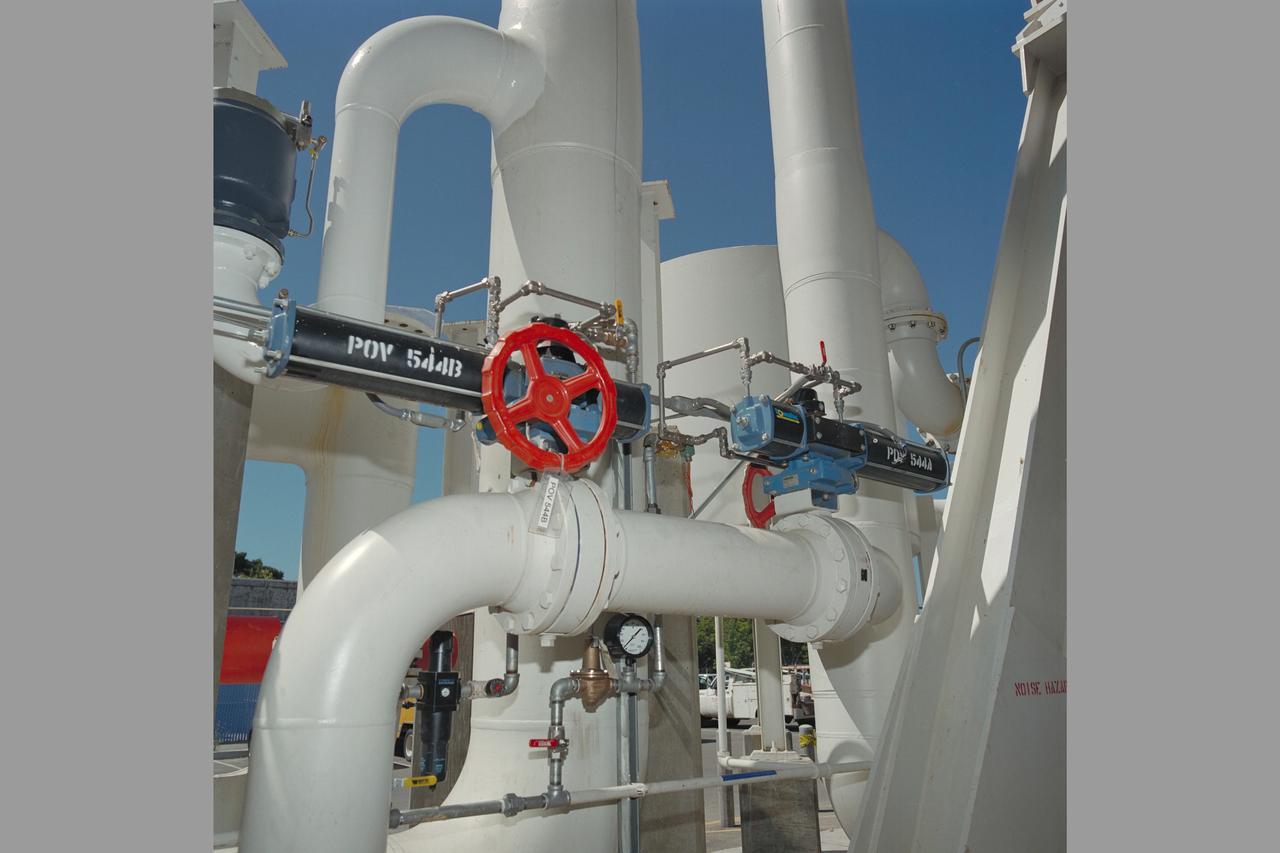
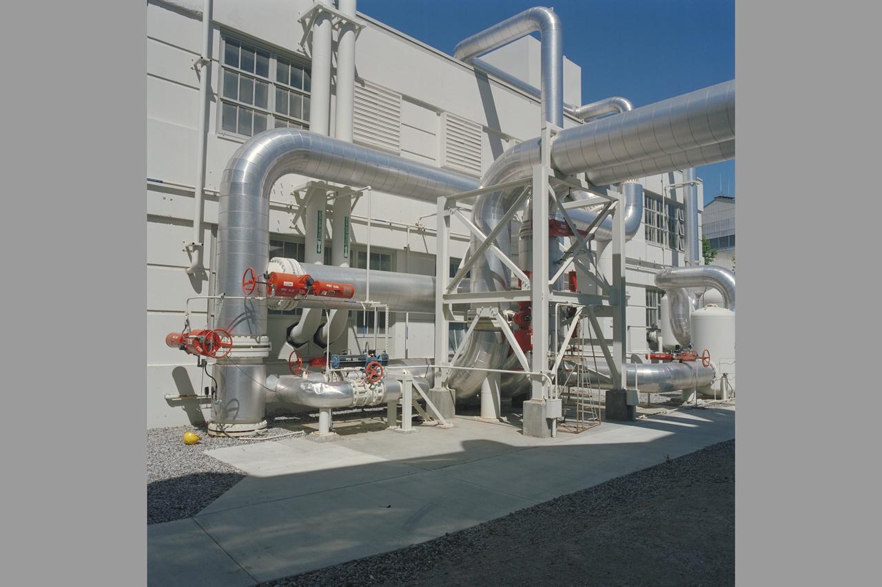
N-206 12ft W.T. ADTE Project (Aeronautics Design and Test Environment) New piping to old valves
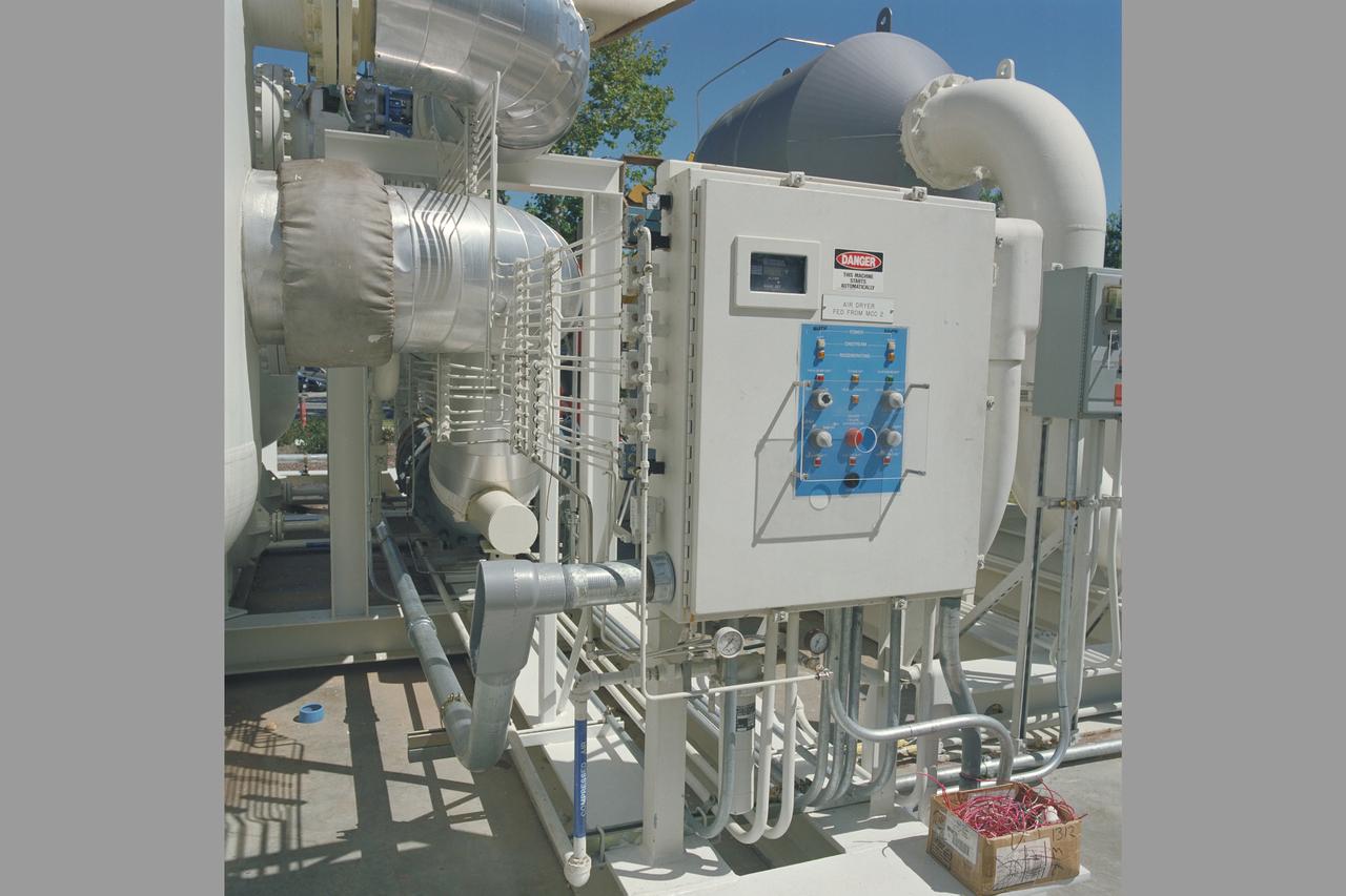
N-206 12ft W.T. ADTE Project (Aeronautics Design and Test Environment) 3' conduit to dry air control panel
N-206 12ft W.T. ADTE Project (Aeronautics Design and Test Environment) Dryer area as is (N-206A)
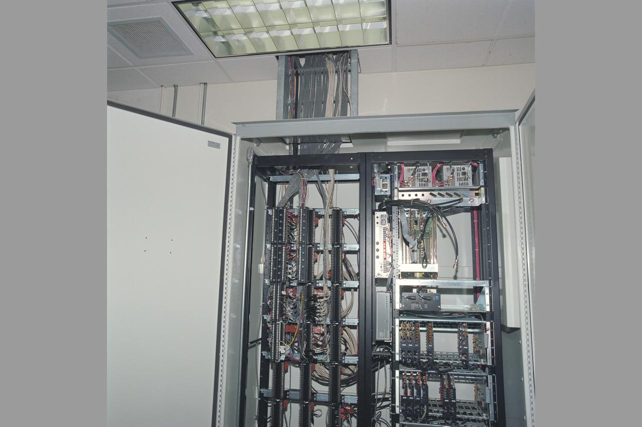
N-206 12ft W.T. ADTE Project (Aeronautics Design and Test Environment) controller drop #5 (N-206A)
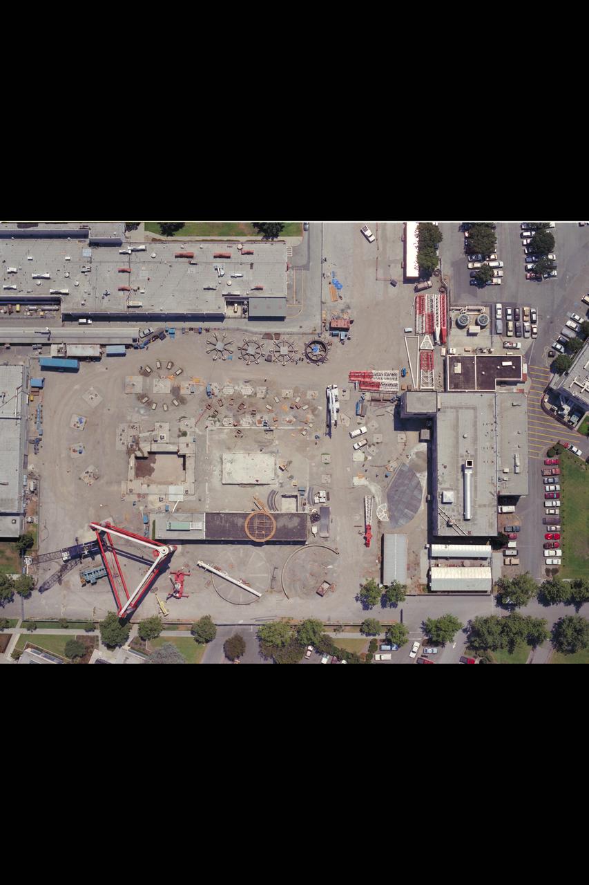
N-206 12ft. PWT Reconstruction Aerial: foundation and begining crane assembly
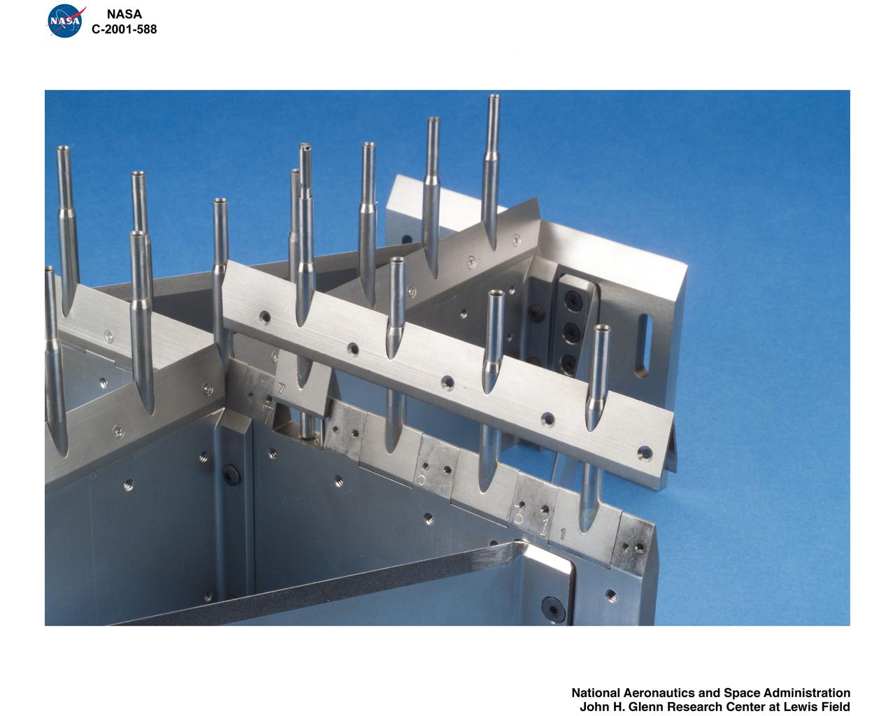
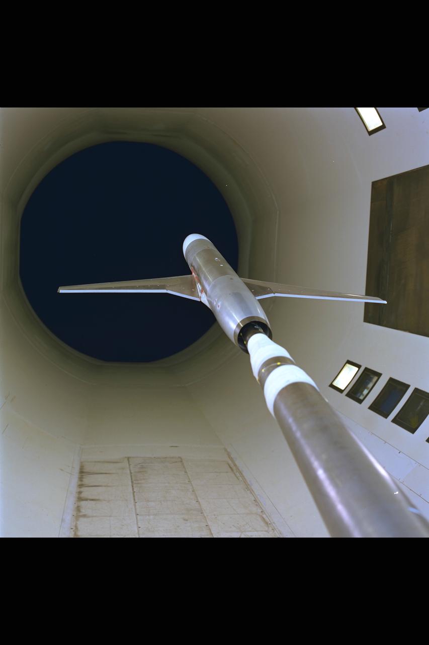
1X1 FOOT WIND TUNNEL PRESSURE RAKE
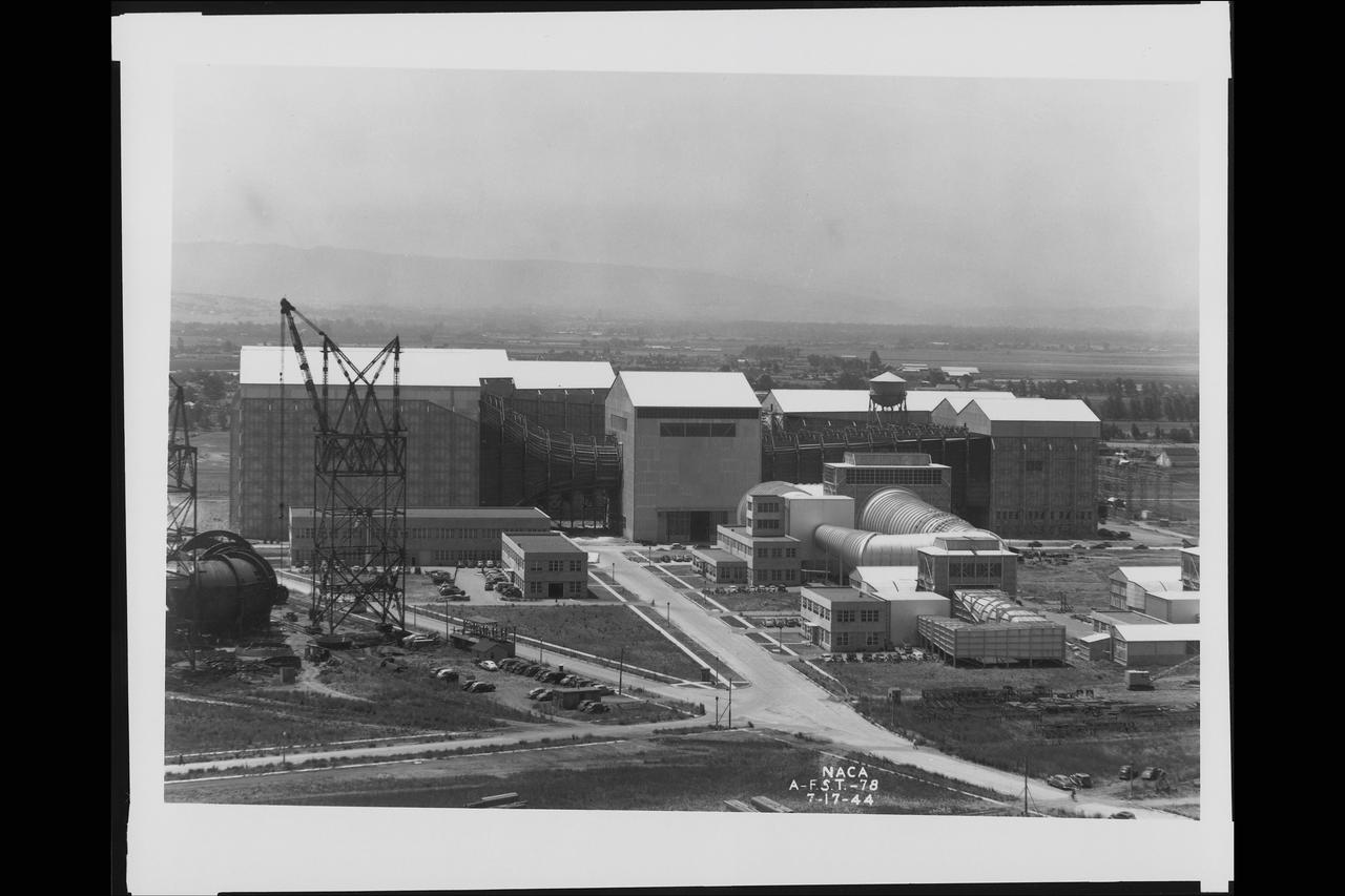
General view of Ames Subsonic 40x80ft wind tunnel from atop of the Moffett Naval Airship Hangar One (with construction of the Ames 12ft Pressure Wind Tunnel in forground) July 17, 1944
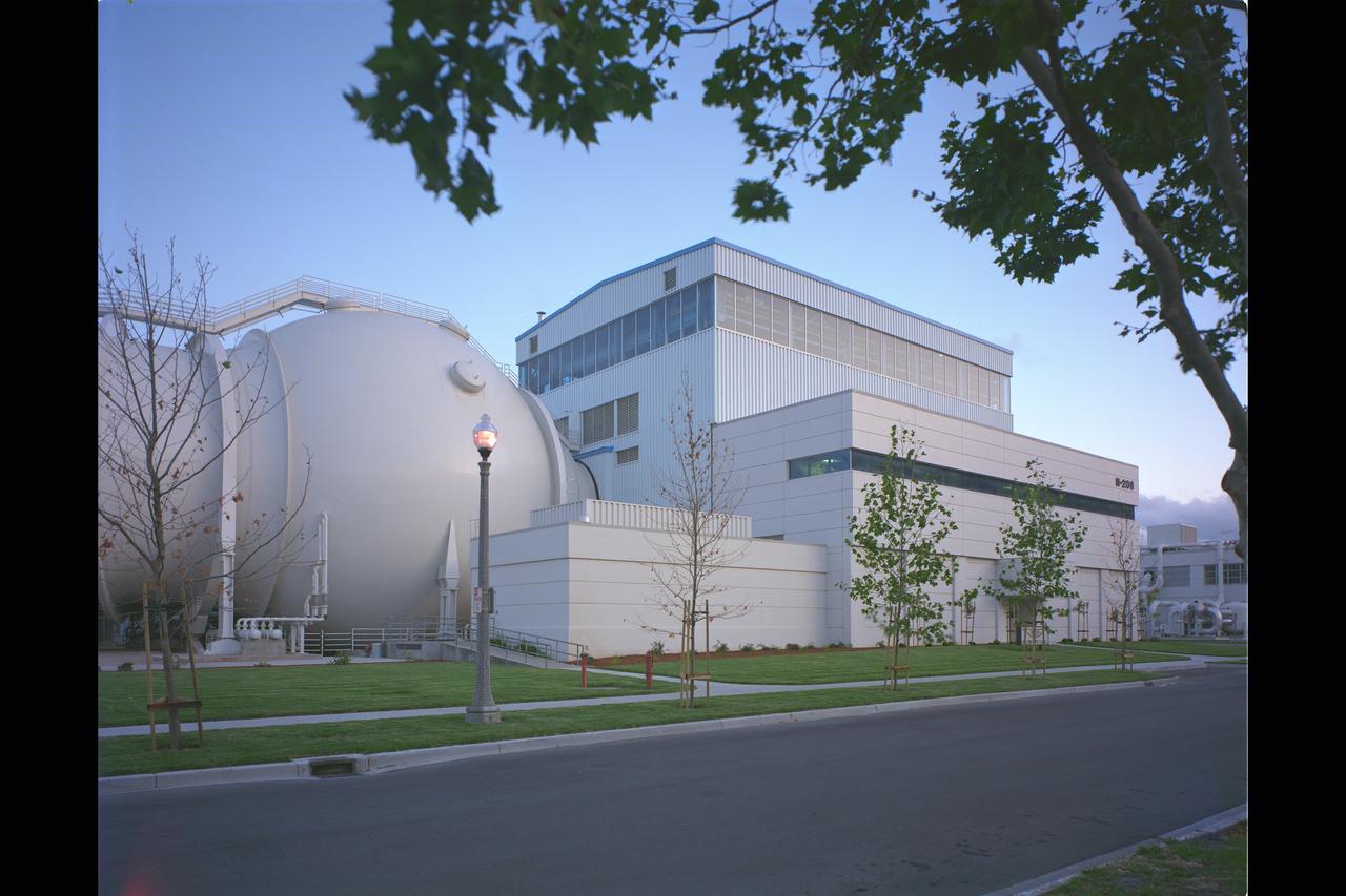
New renovated NASA Ames Research Center 12ft Pressure Wind Tunnel
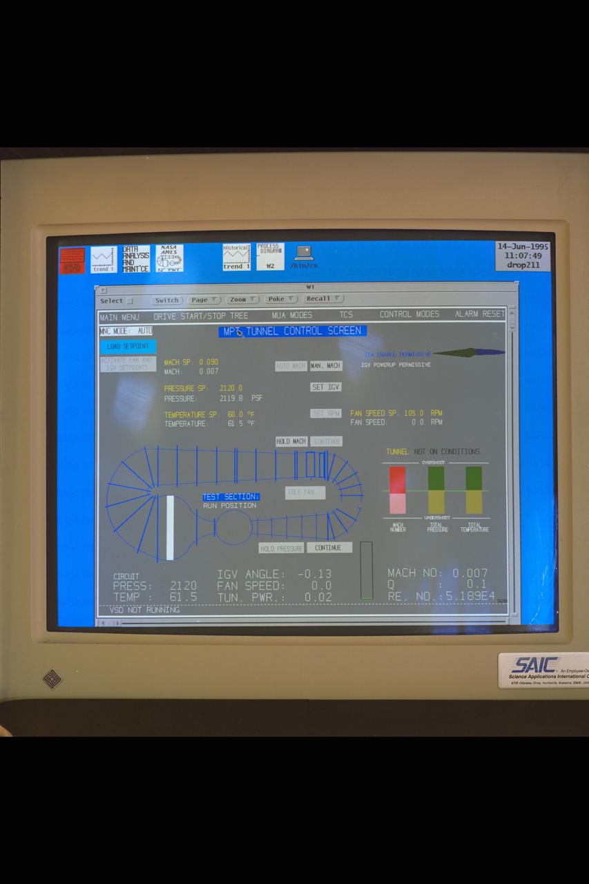
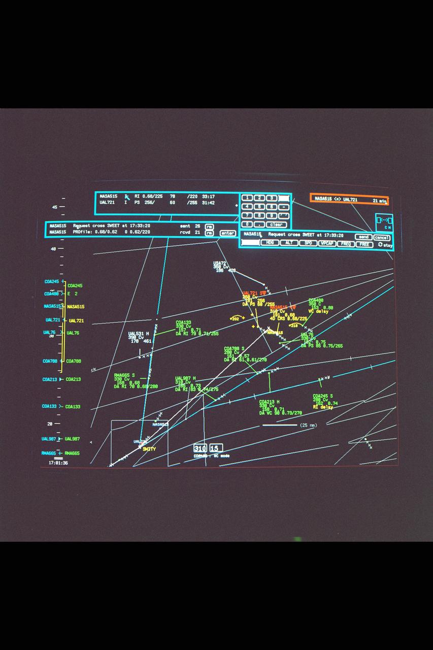
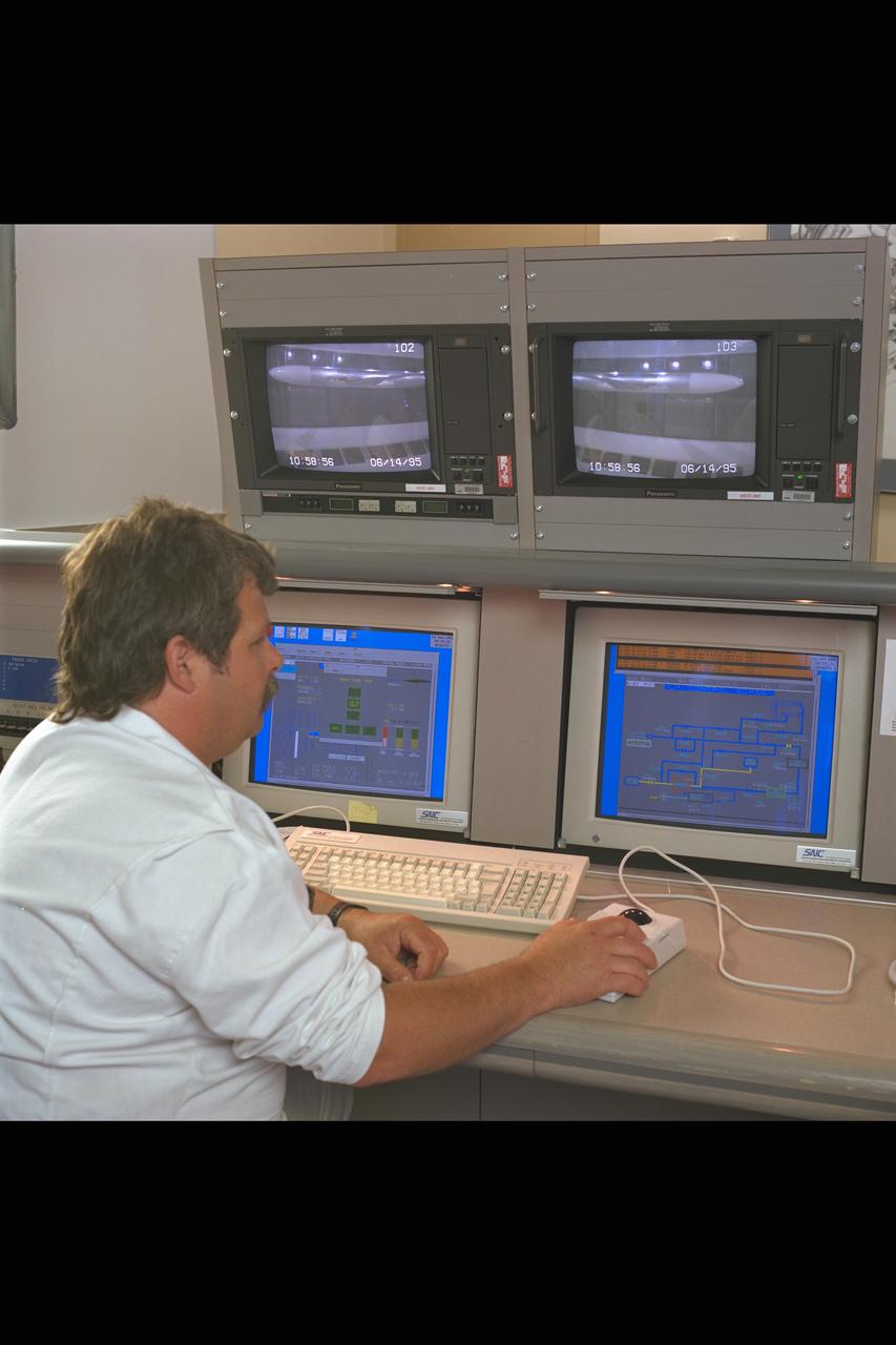
New renovated NASA Ames Research Center 12ft Pressure Wind Tunnel view of control room benchboard operations with tunnel control screen (computer system)
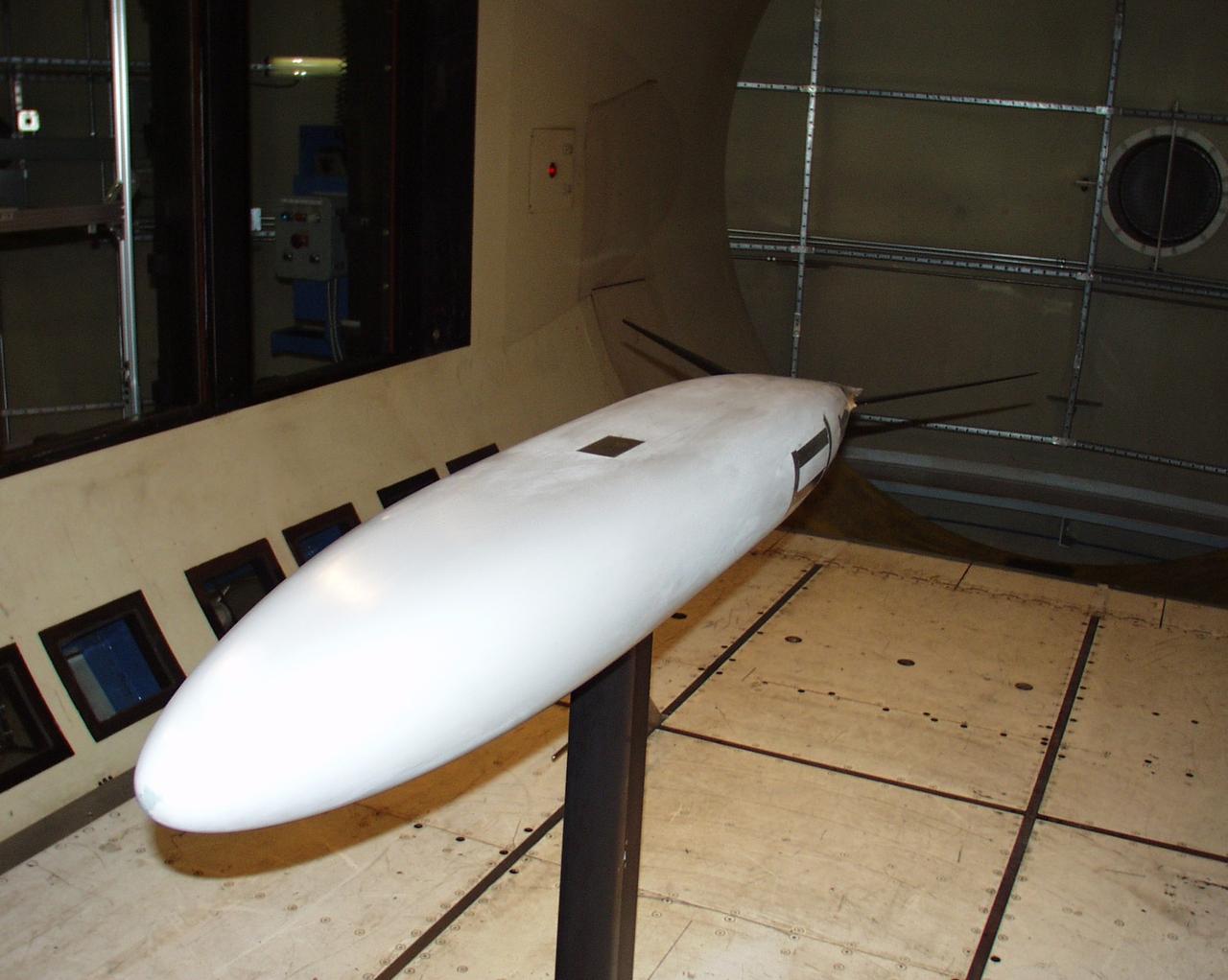
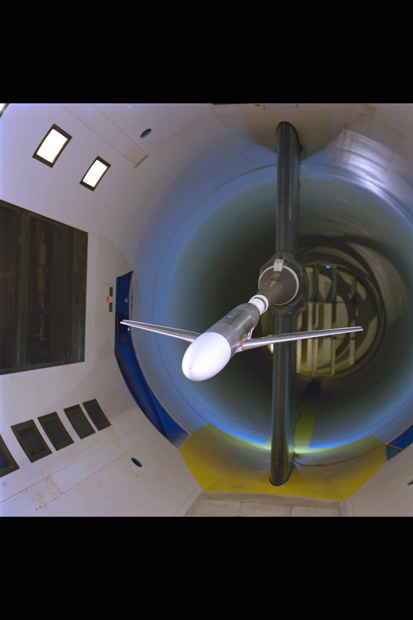
Ames Rotary Entry Vehicle #1 model in REV-1 testing in the Ames Research Center 12ft. Pressure Wind Tunnel
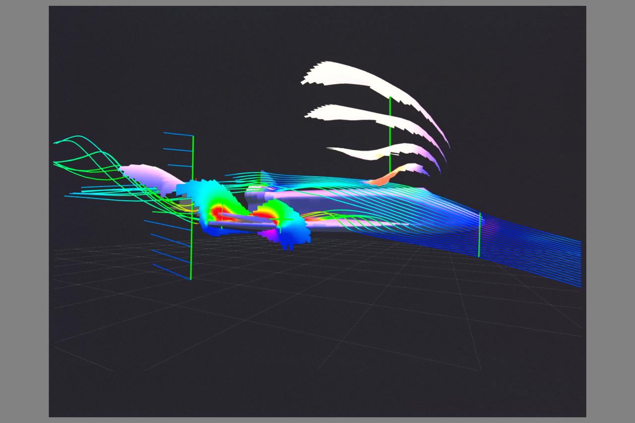
Computational Fluid Dynamics (CFD) image of Space Shuttle Pressure Flow using Virtual Wind Tunnel

CEV model with pressure sensitive paint (PSP) test 11-0148 in the 11ft Ames wind tunnel.
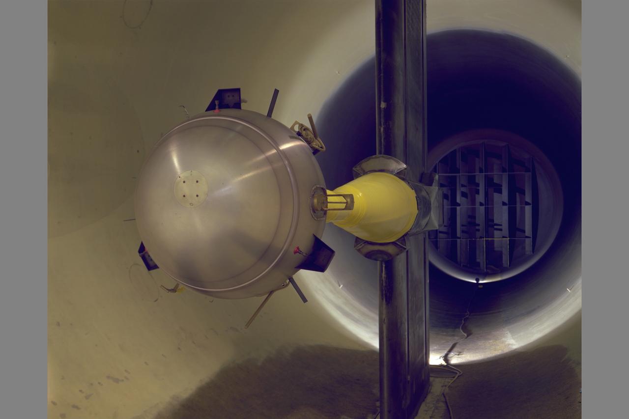
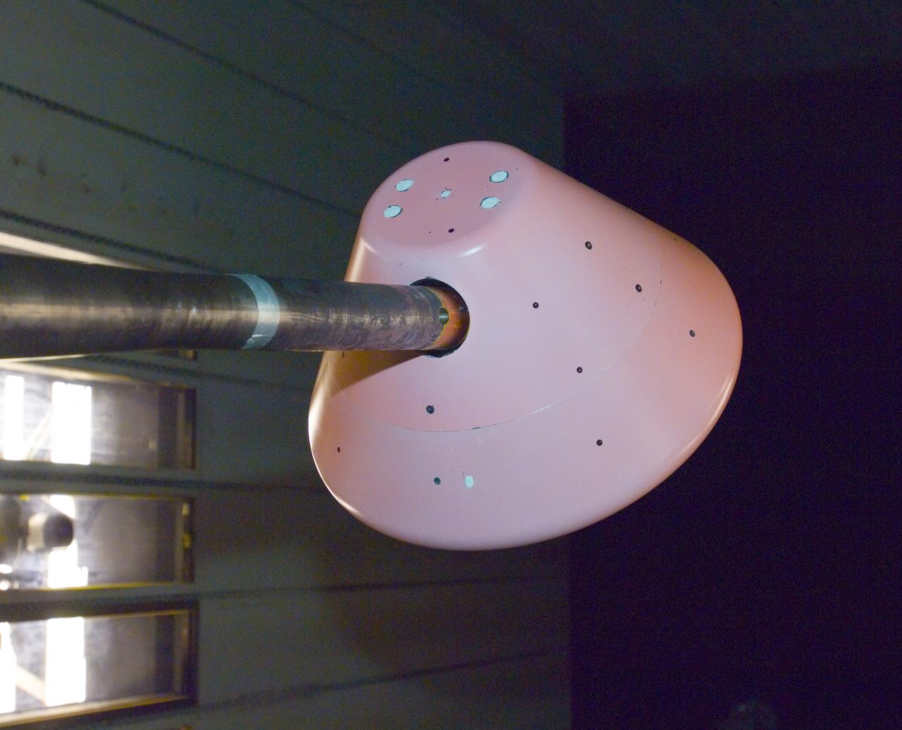
Galileo Probe test-358 in NASA Ames Research Center12ft Pressure Wind Tunnel
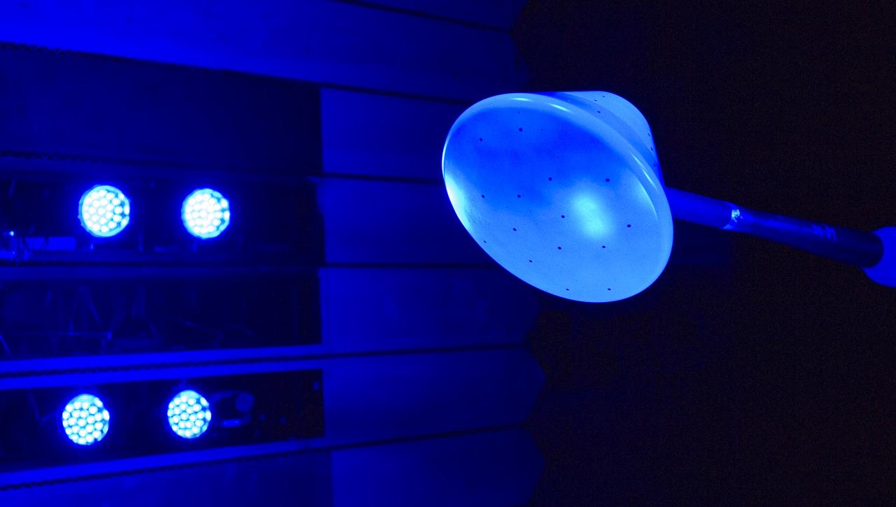
CEV model with pressure sensitive paint (PSP) test 11-0148 in the 11ft Ames wind tunnel
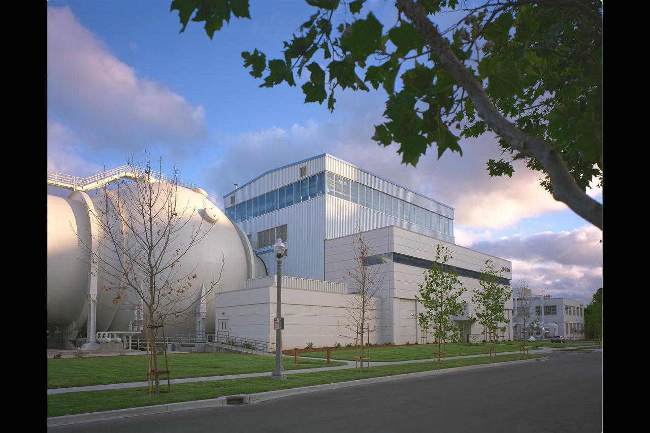
New renovated NASA Ames Research Center 12ft Pressure Wind Tunnel (with clouds)
CEV model with pressure sensitive paint (PSP) test 11-0148 in the 11ft Ames wind tunnel
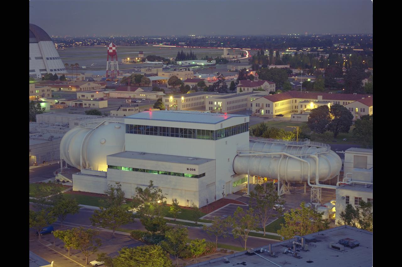
New renovated NASA Ames Research Center 12ft Pressure Wind Tunnel at dusk
Rotary Entry Vehicle model in NASA Ames Reseach Center 12ft Pressure Wind Tunnel
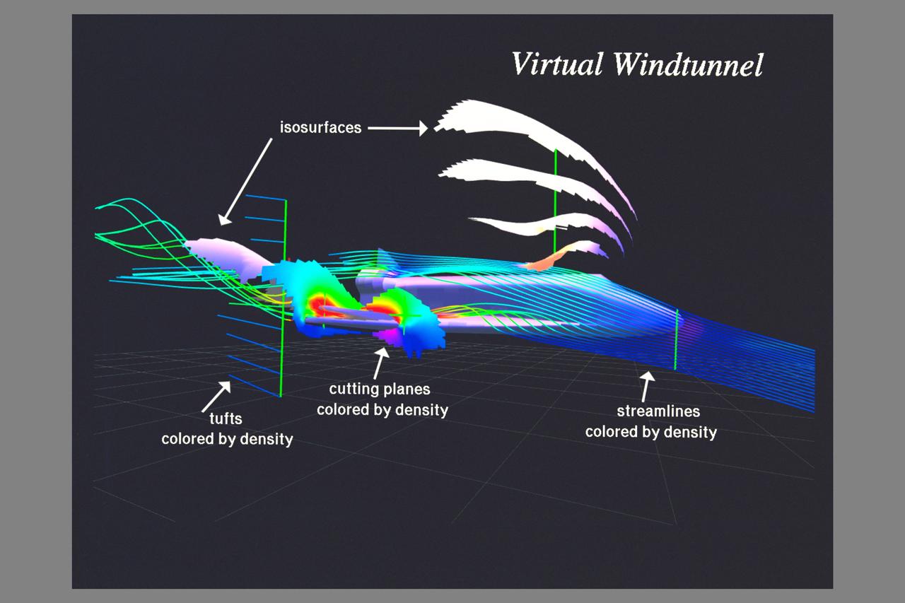
Computational Fluid Dynamics (CFD) image of Space Shuttle Pressure Flow using Virtual Wind Tunnel
New renovated NASA Ames Research Center 12ft Pressure Wind Tunnel view of control room
New renovated NASA Ames Research Center 12ft Pressure Wind Tunnel view of mechanic with mdoel in model prep area
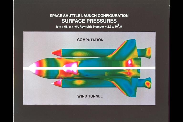
CFD: Space Shuttle Launch Configuration surface pressure comparison (right) computation and wind tunnel
CEV model with pressure sensitive paint (PSP) test 11-0148 in the 11ft Ames wind tunnel
New renovated NASA Ames Research Center 12ft Pressure Wind Tunnel view model prep area
New renovated NASA Ames Research Center Ames 12ft Pressure Wind Tunnel view of test section
CEV model with pressure sensitive paint (PSP) test 11-0148 in the 11ft Ames wind tunnel
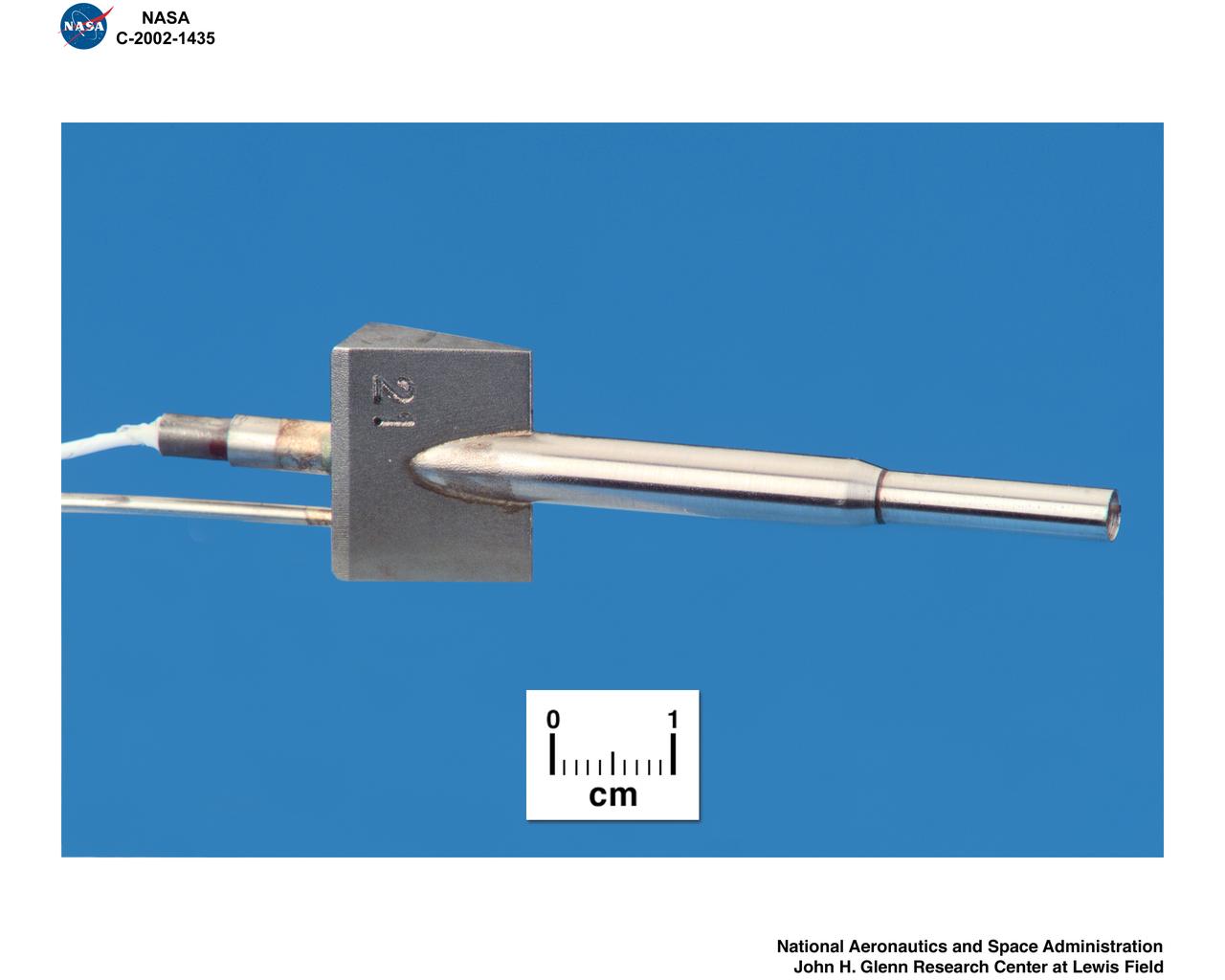
INDIVIDUAL PITOT PROBE - 1 FT X 1 FT WIND TUNNEL PRESSURE RAKE
New renovated NASA Ames Research Center 12 foot Pressure Wind Tunnel, vanes
CEV model with pressure sensitive paint (PSP) test 11-0148 in the 11ft Ames wind tunnel
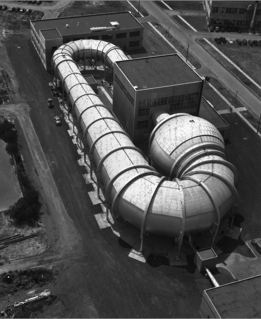
NACA photographer Aerial view newly completed NACA Ames Research Center 12ft Pressure Wind Tunnel N-206
New renovated NASA Ames Research Center 12ft Pressure Wind Tunnel view of mode prep area
New renovated NASA Ames Research Center 12ft Pressure Wind Tunnel view from back of test section with model LB-435, showing tunnel closed
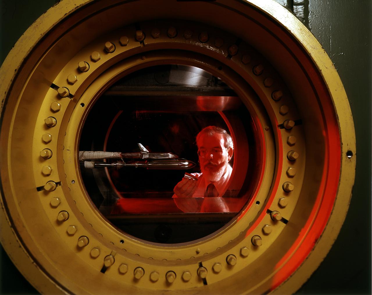
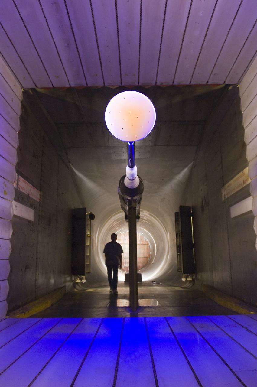
An engineer at the Marshall Space Flight Center (MSFC) observes a model of the Space Shuttle Orbiter being tested in the MSFC's 14x14-Inch Trisonic Wind Tunnel. The 14-Inch Wind Tunnel is a trisonic wind tunnel. This means it is capable of running subsonic, below the speed of sound; transonic, at or near the speed of sound (Mach 1,760 miles per hour at sea level); or supersonic, greater than Mach 1 up to Mach 5. It is an intermittent blowdown tunnel that operates by high pressure air flowing from storage to either vacuum or atmospheric conditions. The MSFC 14x14-Inch Trisonic Wind Tunnel has been an integral part of the development of the United States space program Rocket and launch vehicles from the Jupiter-C in 1958, through the Saturn family up to the current Space Shuttle and beyond have been tested in this Wind Tunnel. MSFC's 14x14-Inch Trisonic Wind Tunnel, as with most other wind tunnels, is named after the size of the test section. The 14-Inch Wind Tunnel, as in the past, will continue to play a large but unseen role in the development of America's space program.
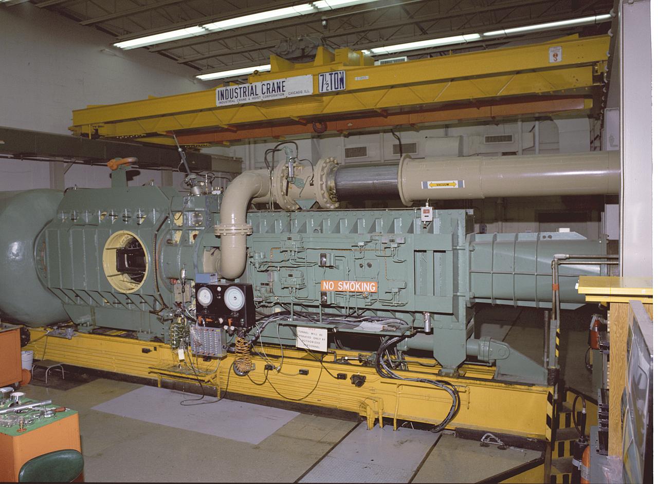
This photograph shows an overall view of the Marshall Space Flight Center's (MSFC's) 14x14-Inch Trisonic Wind Tunnel. The 14-Inch Wind Tunnel is a trisonic wind tunnel. This means it is capable of running subsonic, below the speed of sound; transonic, at or near the speed of sound (Mach 1, 760 miles per hour at sea level); or supersonic, greater than Mach 1 up to Mach 5. It is an intermittent blowdown tunnel that operates by high pressure air flowing from storage to either vacuum or atmospheric conditions. The MSFC 14x14-Inch Trisonic Wind Tunnel has been an integral part of the development of the United States space program Rocket and launch vehicles from the Jupiter-C in 1958, through the Saturn family up to the current Space Shuttle and beyond have been tested in this Wind Tunnel. MSFC's 14x14-Inch Trisonic Wind Tunnel, as with most other wind tunnels, is named after the size of the test section. The 14-Inch Wind Tunnel, as in the past, will continue to play a large but unseen role in the development of America's space program.
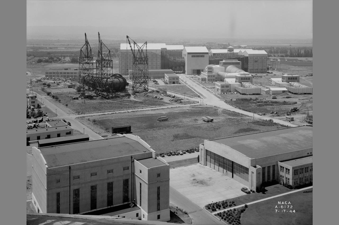
General view of Ames Aeronautical Laboratory taken from Naval airship hangar. Shows construction of the 12ft Pressure Wind Tunnel with large cranes.
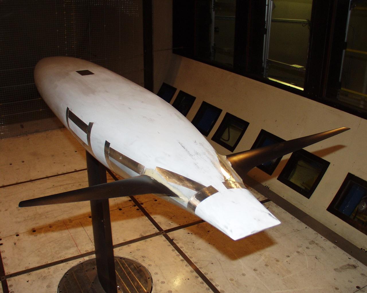
3% Space Shuttle Model Testing for Return to flight in the Ames 9X7ft wind tunnel test T97-0131 (IA-700B) with pressure sensitive paint
3% Space Shuttle Model Testing for Return to flight in the Ames 9X7ft wind tunnel test T97-0131 (IA-700B) with pressure sensitive paint
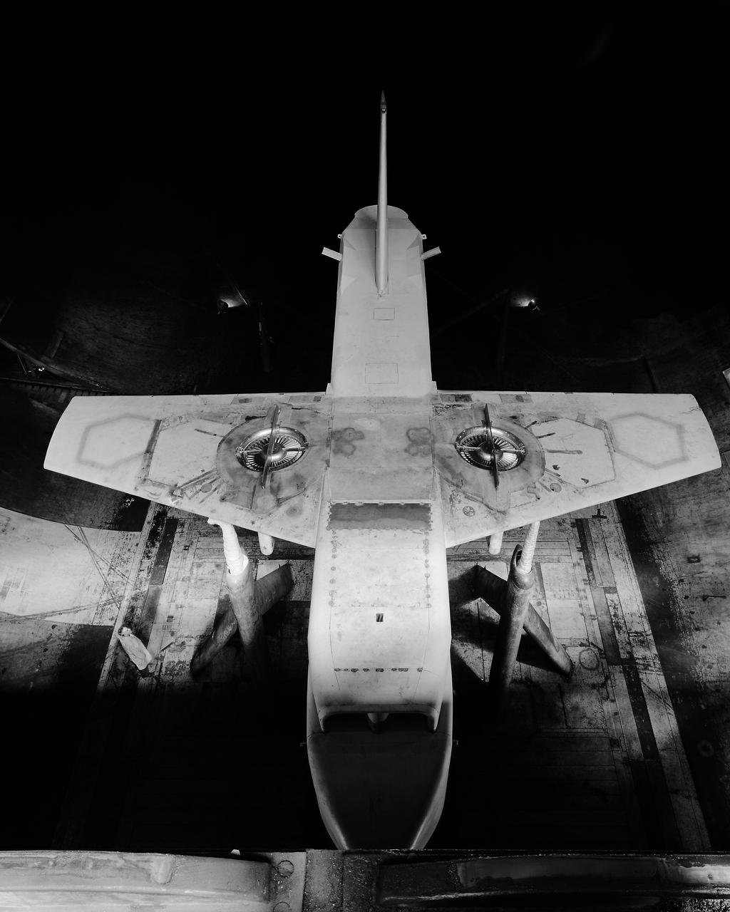
3% Space Shuttle Model Testing for Return to flight in the Ames 9X7ft wind tunnel test T97-0131 (IA-700B) with pressure sensitive paint
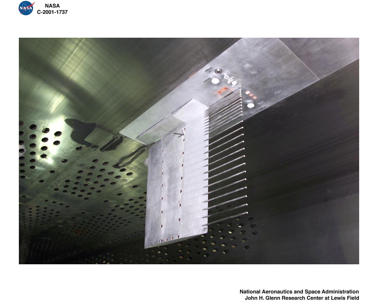
8X6 FOOT SUPERSONIC WIND TUNNEL TEST OF NASA DRYDEN FLIGHT RESEARCH CENTER SKIN FRICTION GAUGES WITH PRESSURE GAUGES AND HOT FILMS
3% Space Shuttle Model Testing for Return to flight in the Ames 9X7ft wind tunnel test T97-0131 (IA-700B) with pressure sensitive paint
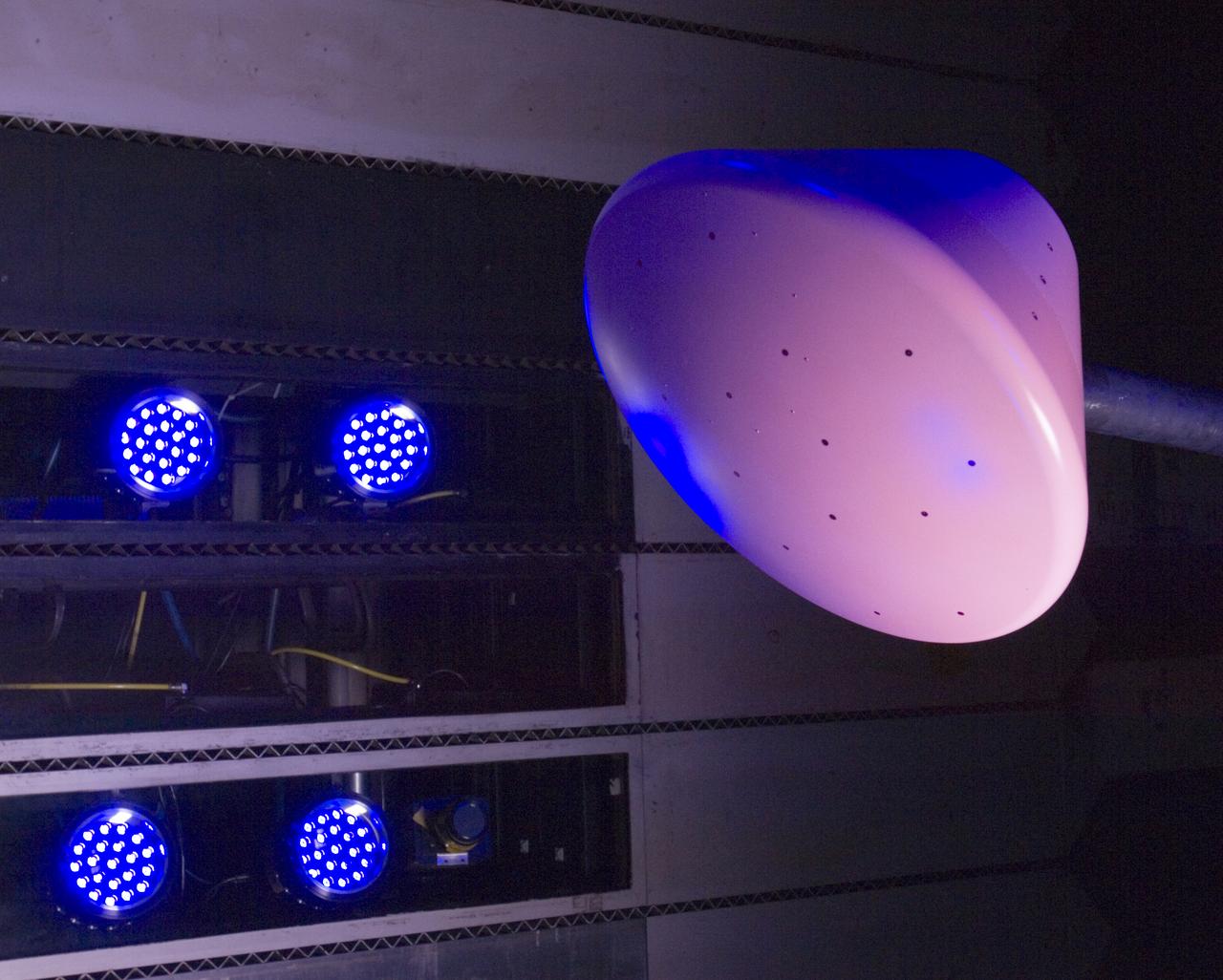
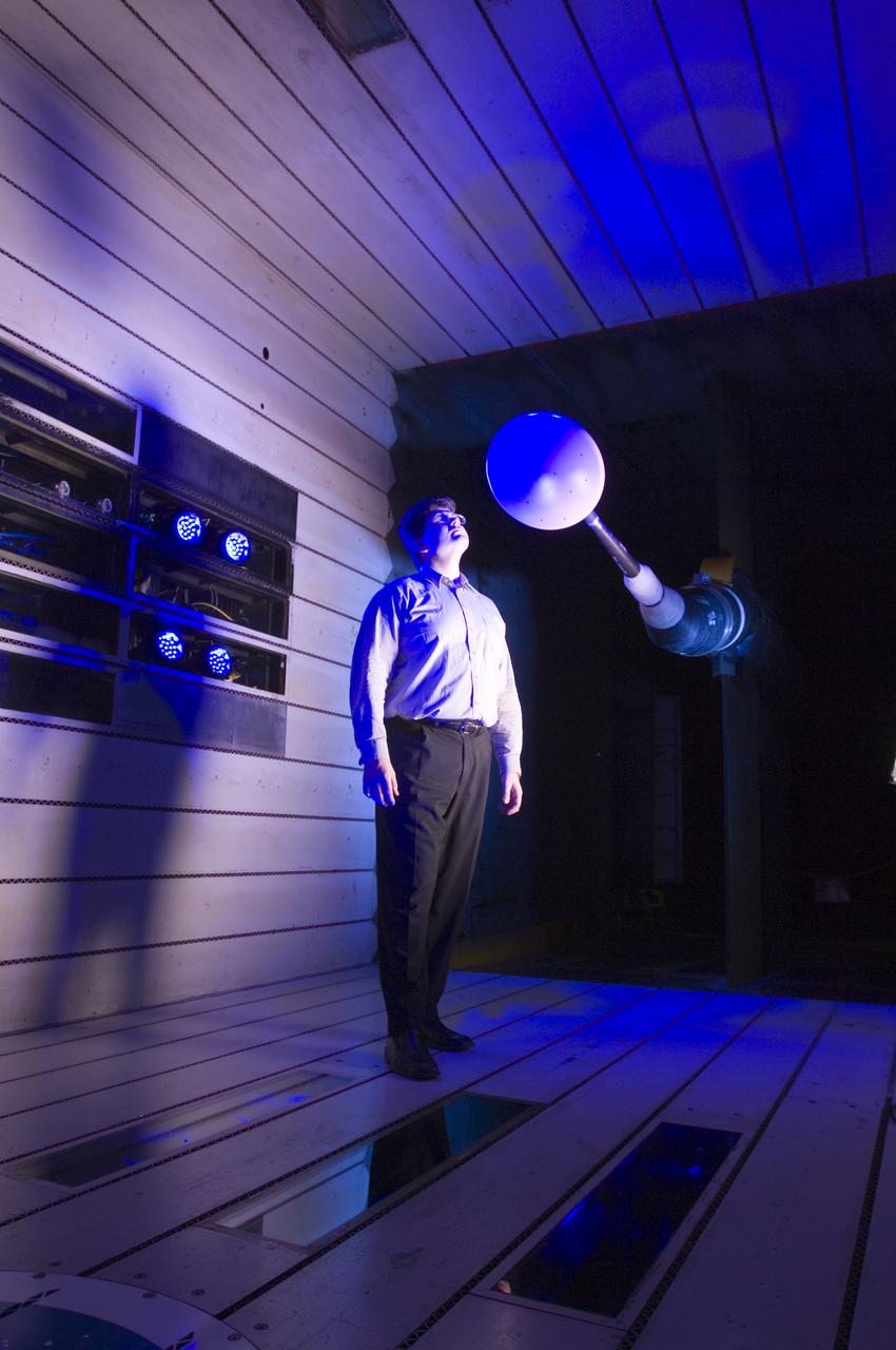
CEV model with pressure sensitive paint (PSP) test 11-0148 in the 11ft Ames wind tunnel. Dave Maurantonio with blue LEDS.
3% Space Shuttle Model Testing for Return to flight in the Ames 9X7ft wind tunnel test T97-0131 (IA-700B) with pressure sensitive paint
New renovated NASA Ames Research Center 12ft Pressure Wind Tunnel view of test section with mechanic checking LB-435 model installed
3% Space Shuttle Model Testing for Return to flight in the Ames 9X7ft wind tunnel test T97-0131 (IA-700B) with pressure sensitive paint
New renovated NASA Ames Research Center 12ft Pressure Wind Tunnel view of test section as 2 mechanics inspect model installation
New renovated NASA Ames Research Center 12ft Pressure Wind Tunnel view of test section with LB-435 model installed
CEV model with pressure sensitive paint (PSP) test 11-0148 in the 11ft Ames wind tunnel. Joe Olejniczak with blue LEDS.
3% Space Shuttle Model Testing for Return to flight in the Ames 9X7ft wind tunnel test T97-0131 (IA-700B) with pressure sensitive paint
New renovated NASA Ames Research Center 12ft Pressure Wind Tunnel view of test section with LB-435 model installed

CEV model with pressure sensitive paint (PSP) test 11-0148 in the 11ft Ames wind tunnel. Danny Ompoc preparing for testing.
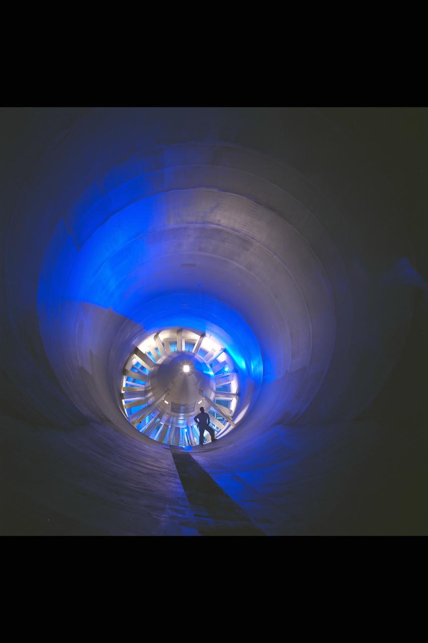
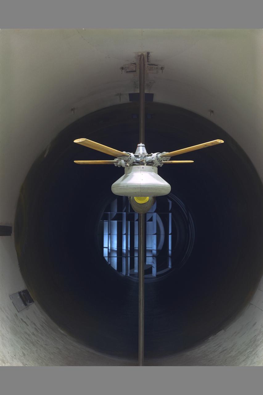
New renovated NASA Ames Research Center 12 foot Pressure Wind Tunnel, seen here is the single stage, 20 blade axial-flow fan powered by a 15,000 horsepower variable speed, synchronous electric motor that provides airflow in the closed-return, variable-density tunnel.
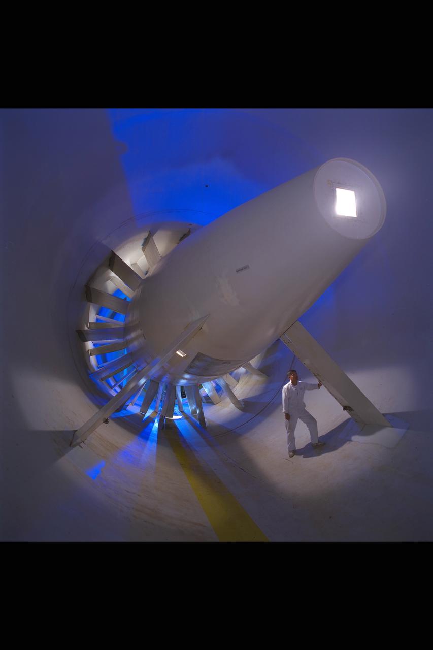
New renovated NASA Ames Research Center 12 foot Pressure Wind Tunnel, seen here is the single stage, 20 blade axial-flow fan powered by a 15,000 horsepower variable speed, synchronous electric motor that provides airflow in the closed-return, variable-density tunnel.
One World Challenge: boat hull configuration optimization test 12-0095 in Ames 12ft pressure wind tunnel. (Three phase Dec 2000 thru May 2002 - America Cup Sailing)
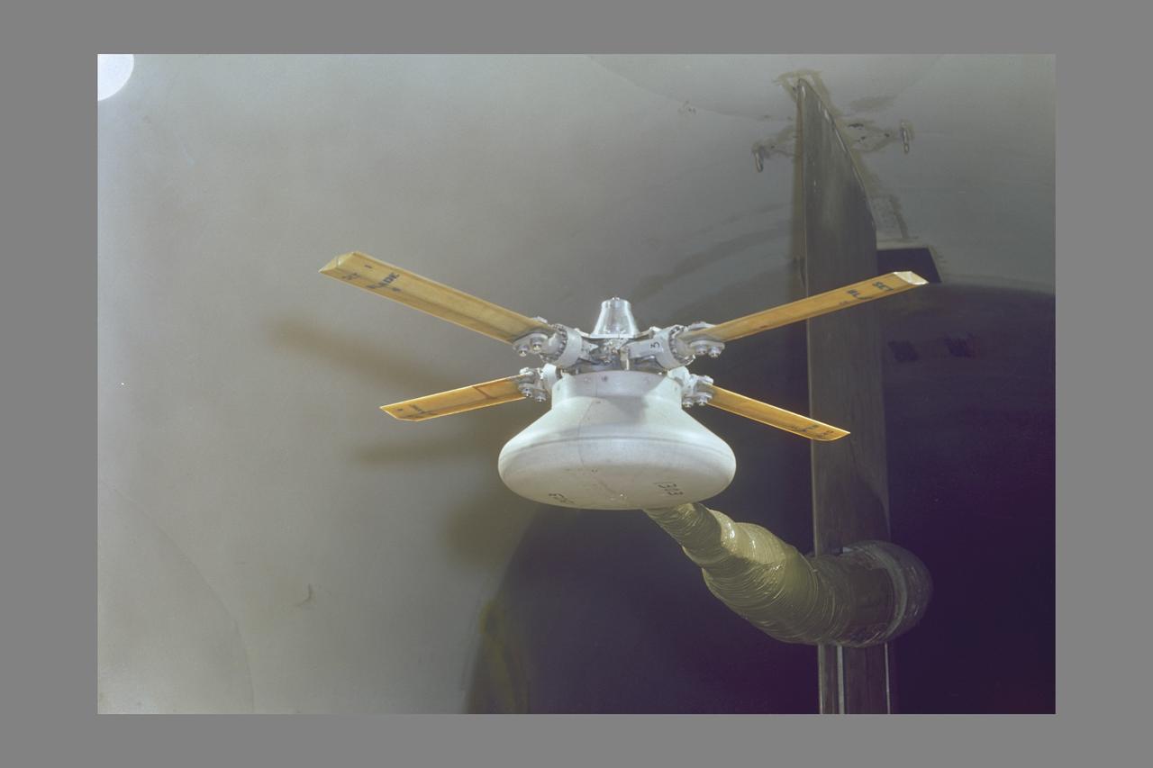
Forward overhead view of lift fan transport model, with two, of a possible six, high pressure ratio wing lift fans. Lift Fan Model In 40 X 80 Wind Tunnel; Test 40-347
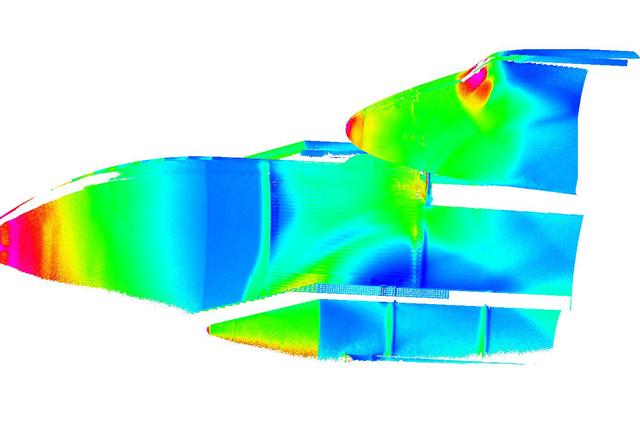
3% Space Shuttle Model Testing for Return to flight in the Ames 9X7ft wind tunnel test T97-0131 (IA-700B) showing data images created with pressure sensitive paint used on mode during the test run.
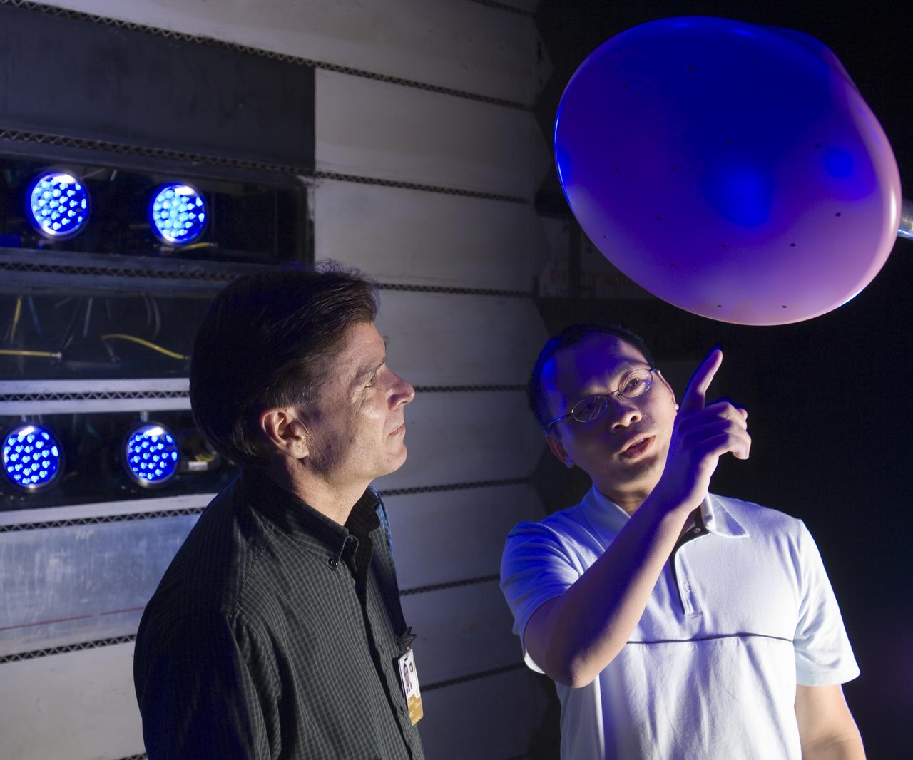
CEV model with pressure sensitive paint (PSP) test 11-0148 in the 11ft Ames wind tunnel. Shown here with Paul Espinosa (l) and Tuan Truong (r) wwith blue LEDS
One World Challenge: boat hull configuration optimization test 12-0095 in Ames 12ft pressure wind tunnel. (Three phase Dec 2000 thru May 2002 - America Cup Sailing)
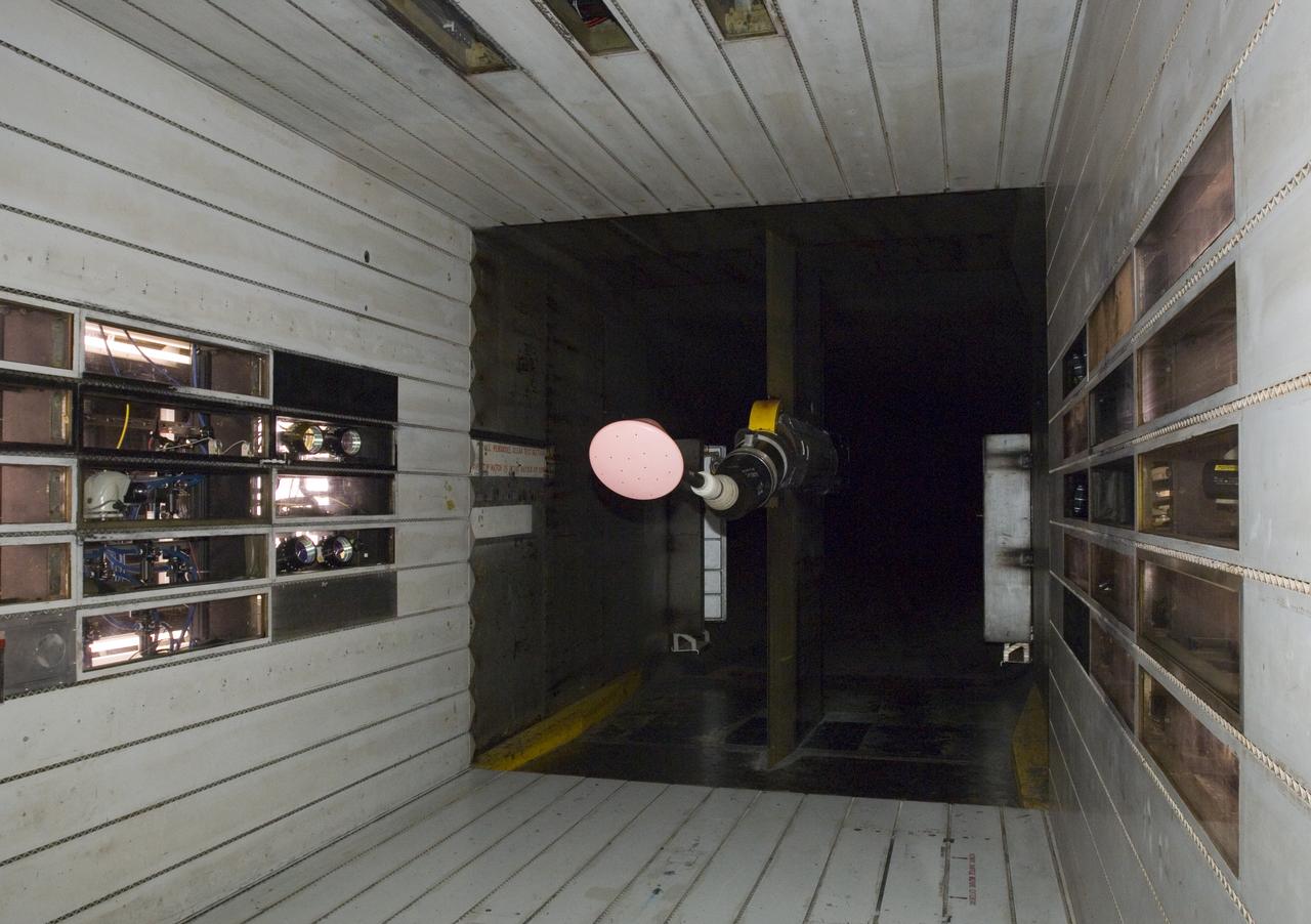
New renovated NASA Ames Research Center 12 foot Pressure Wind Tunnel, test section interior viewed from model installation area (shows airlock)
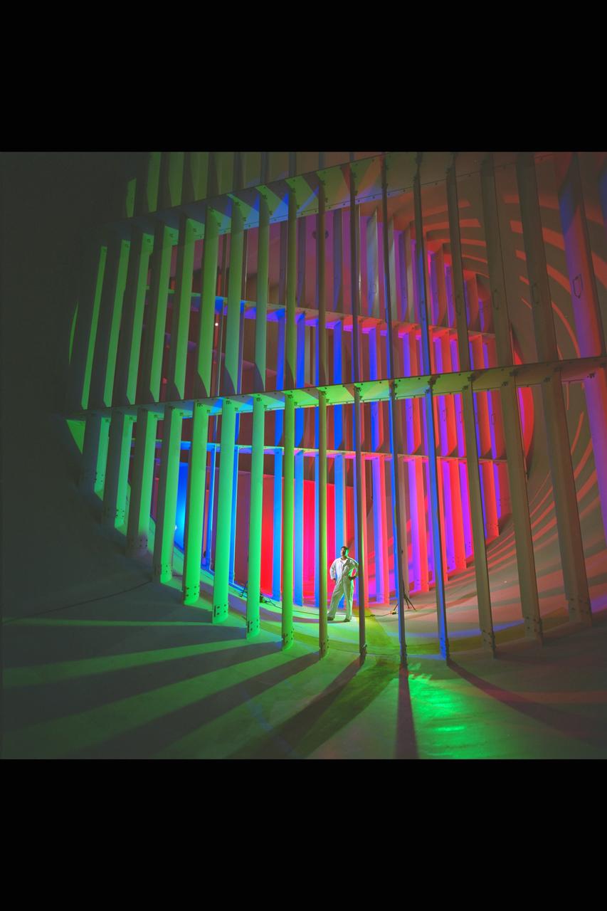
New renovated NASA Ames Research Center 12ft Pressure Wind Tunnel. View of test section with model LB-435 on RSS, showing lighting & viewing windows
New renovated NASA Ames Research Center 12ft Pressure Wind Tunnel view of test section & mechanic with mobil command station, LB-435 model on RSS, lighting & viewing windows
CEV model with pressure sensitive paint (PSP) test 11-0148 in the 11ft Ames wind tunnel. Shown here with Bruce Stroms (l) and James Bell (r).
CEV model with pressure sensitive paint (PSP) test 11-0148 in the 11ft Ames wind tunnel. Shown here with Danny Ompoc (l), Bruce Stroms (m) and James Bell (r).

One World Challenge: boat hull configuration optimization test 12-0095 in Ames 12ft pressure wind tunnel. (Three phase Dec 2000 thru May 2002 - America Cup Sailing)
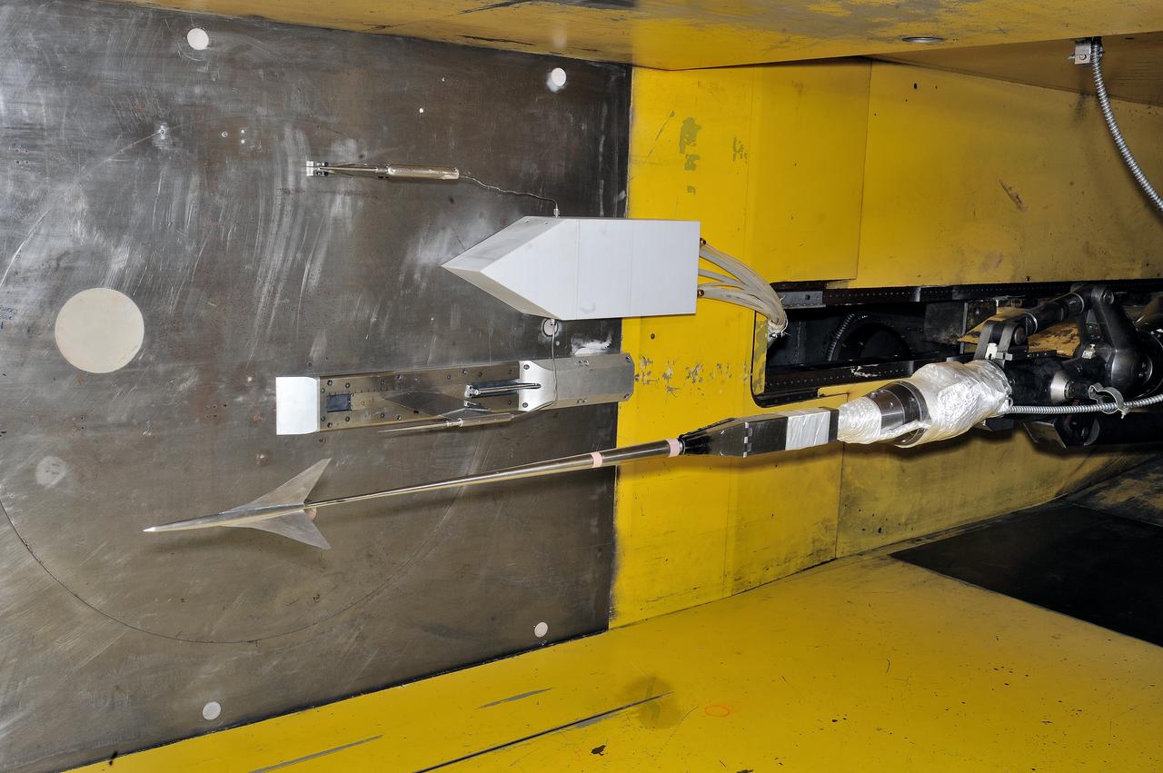
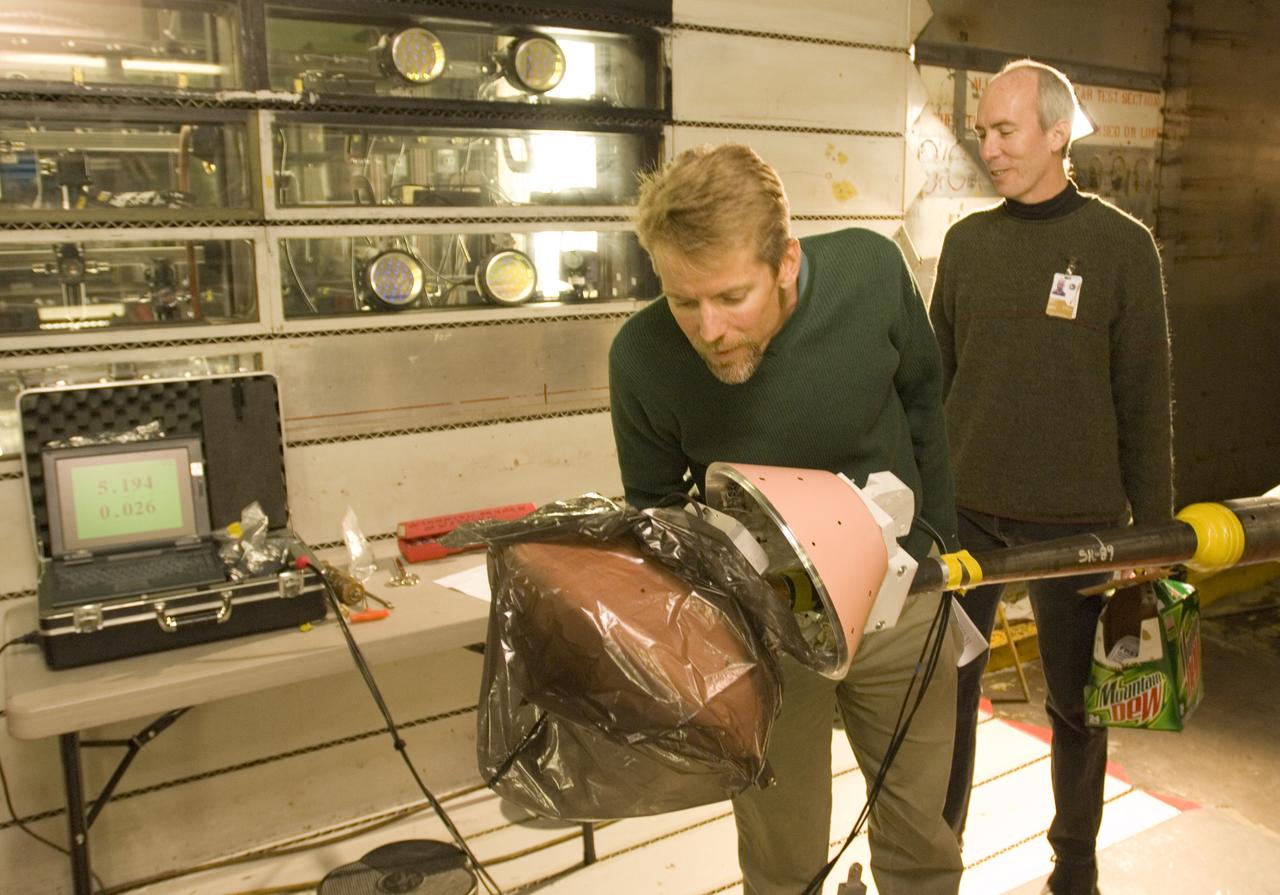
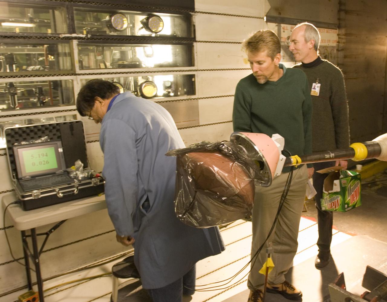
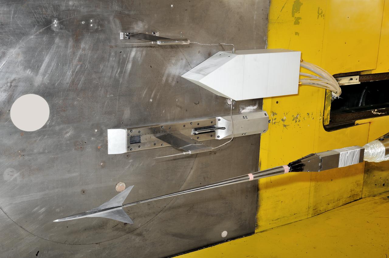
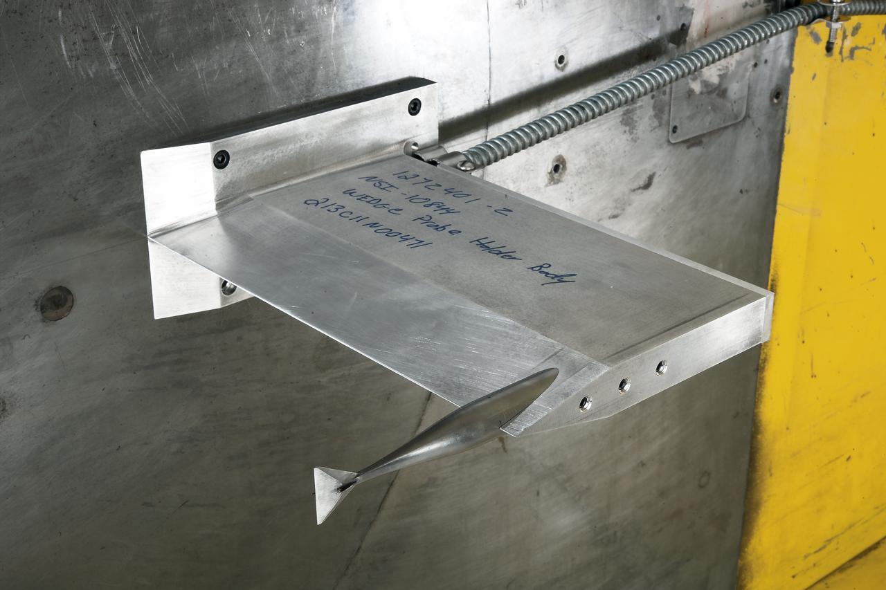
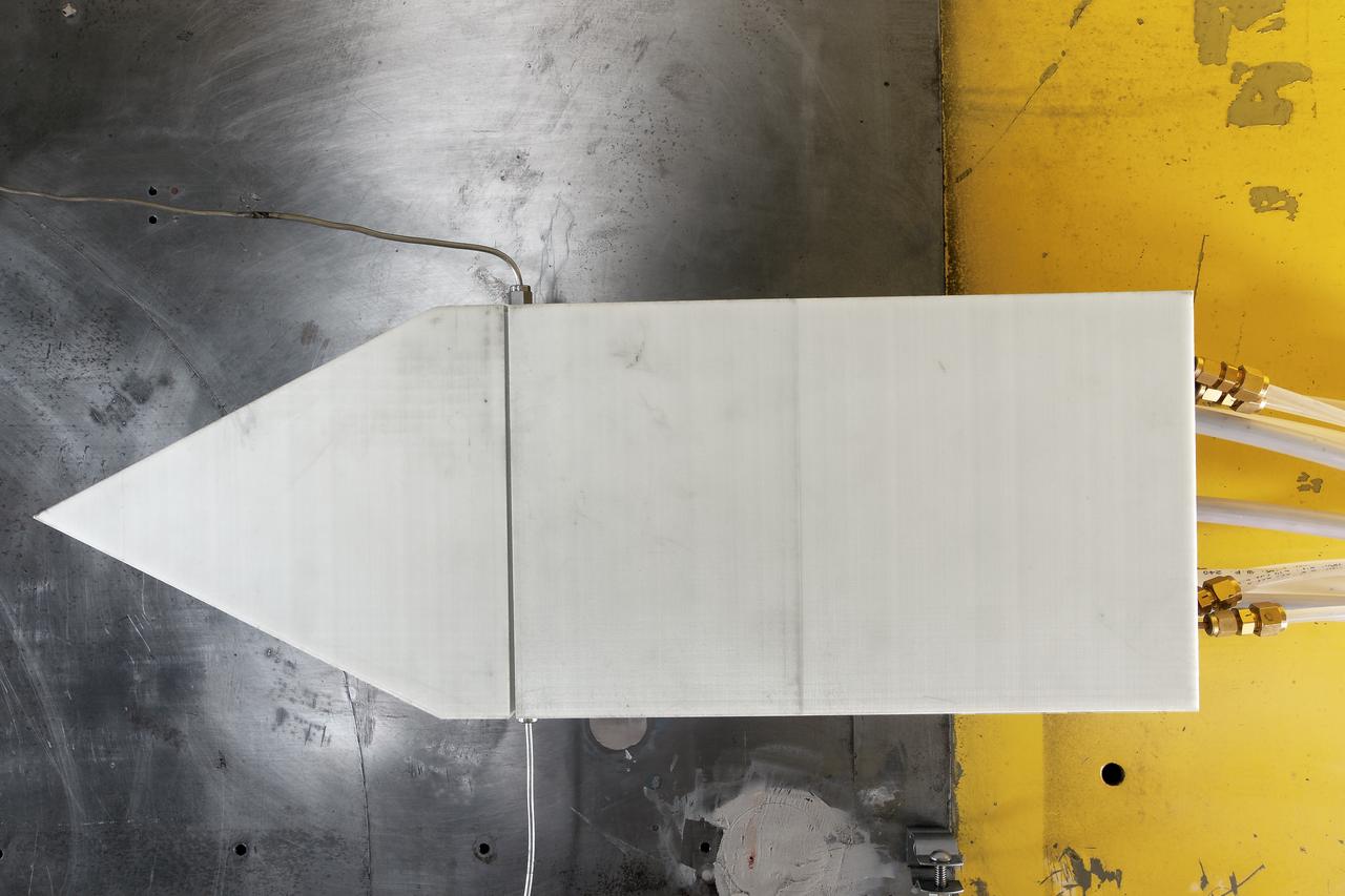
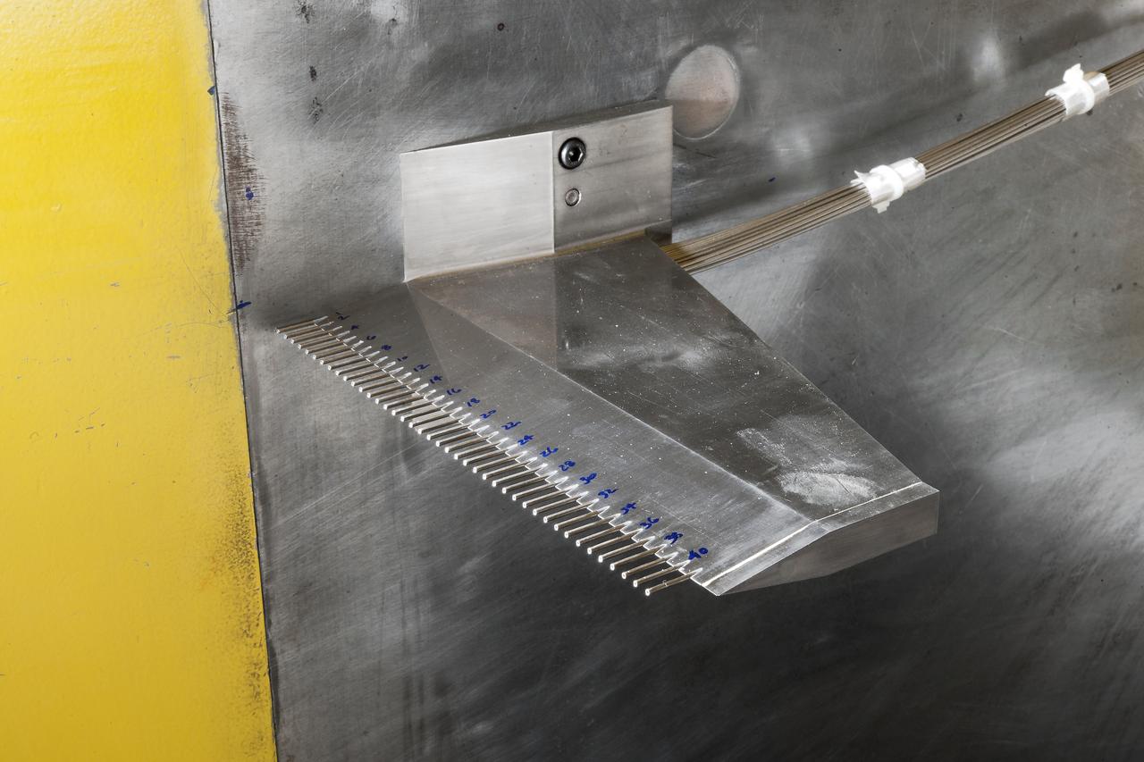
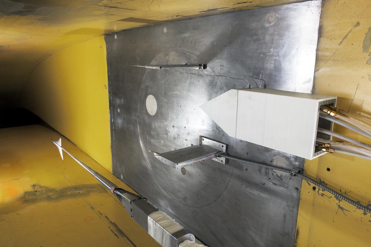
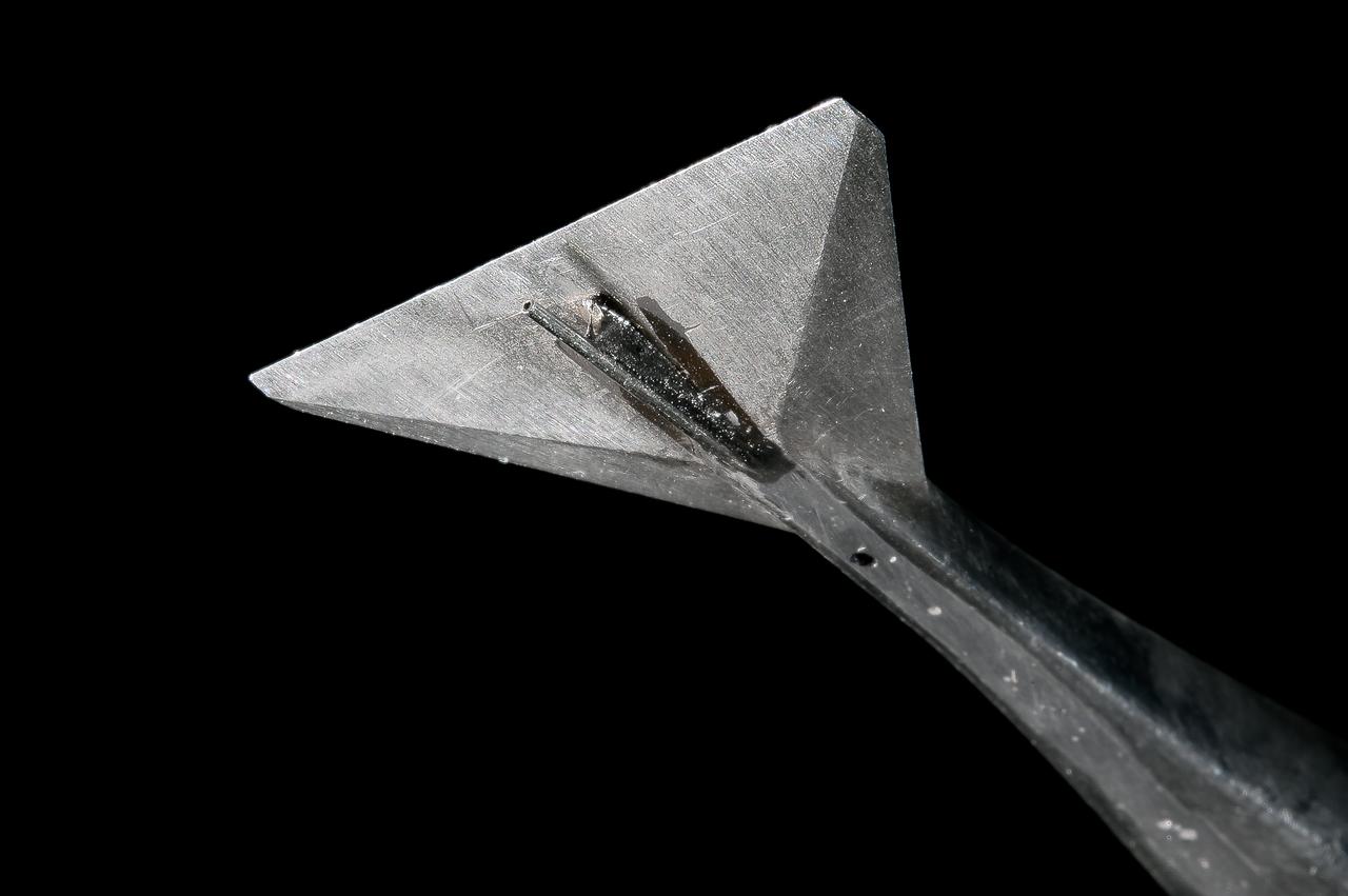
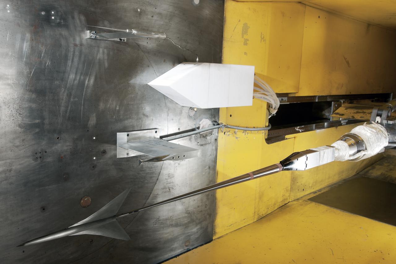
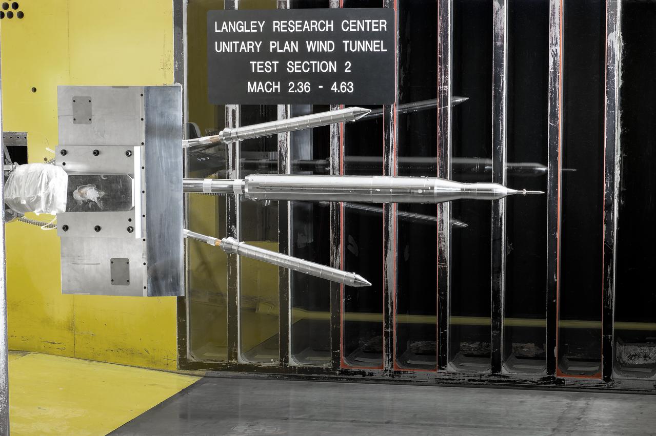
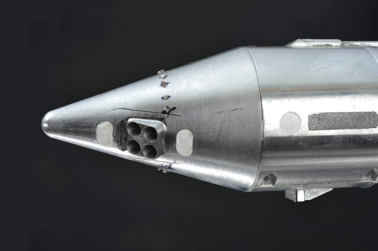
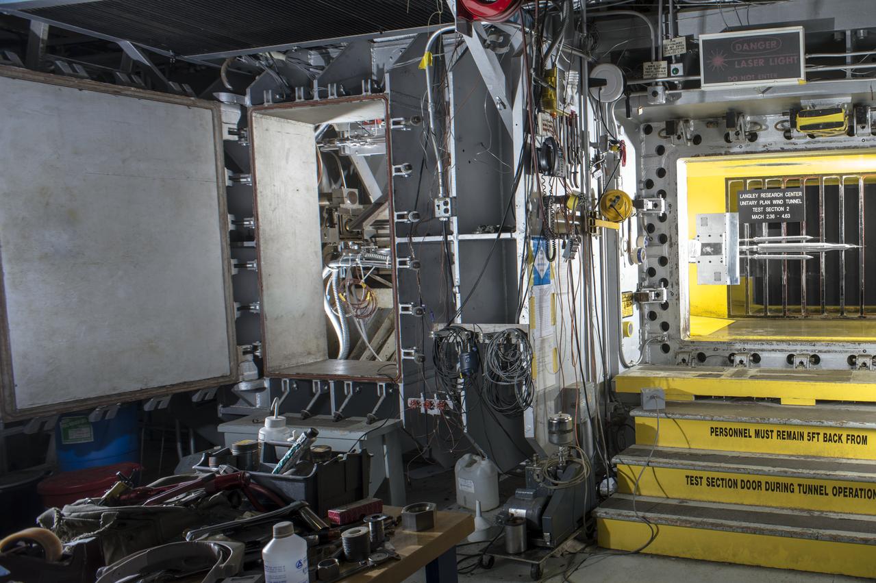
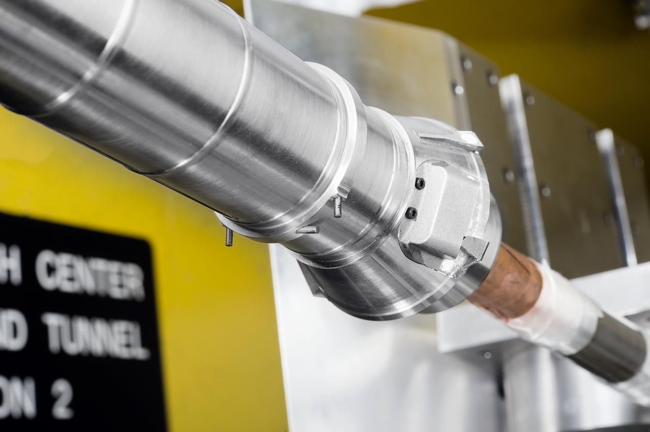
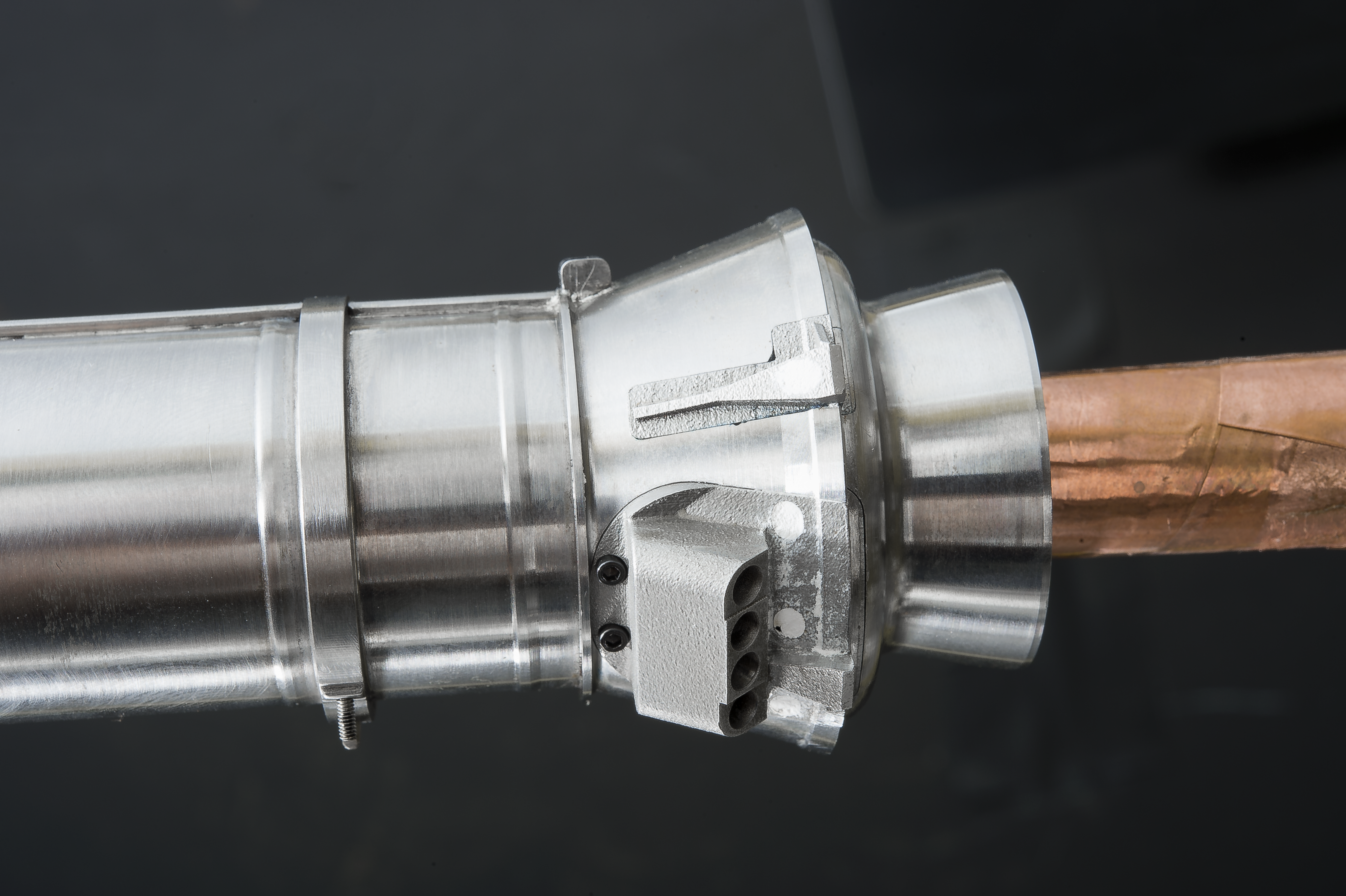
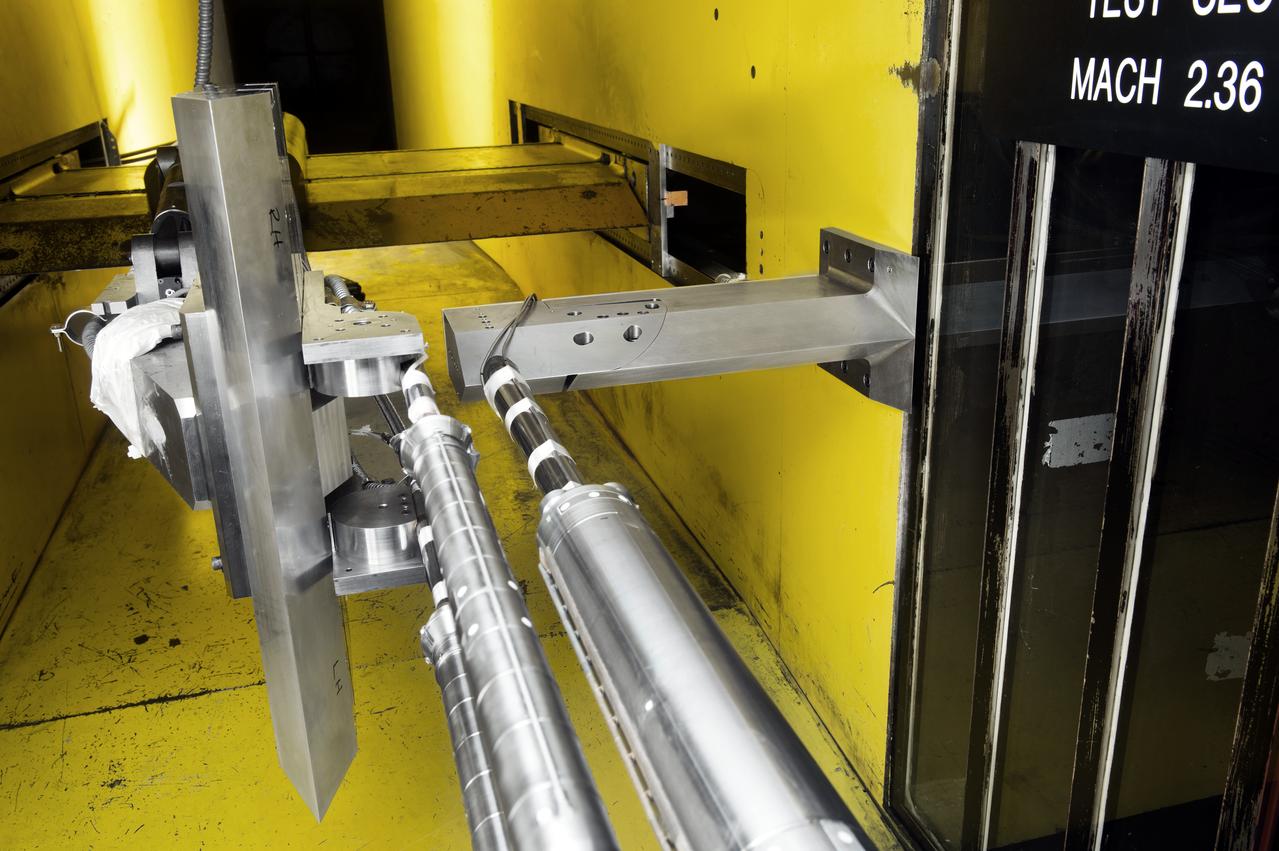
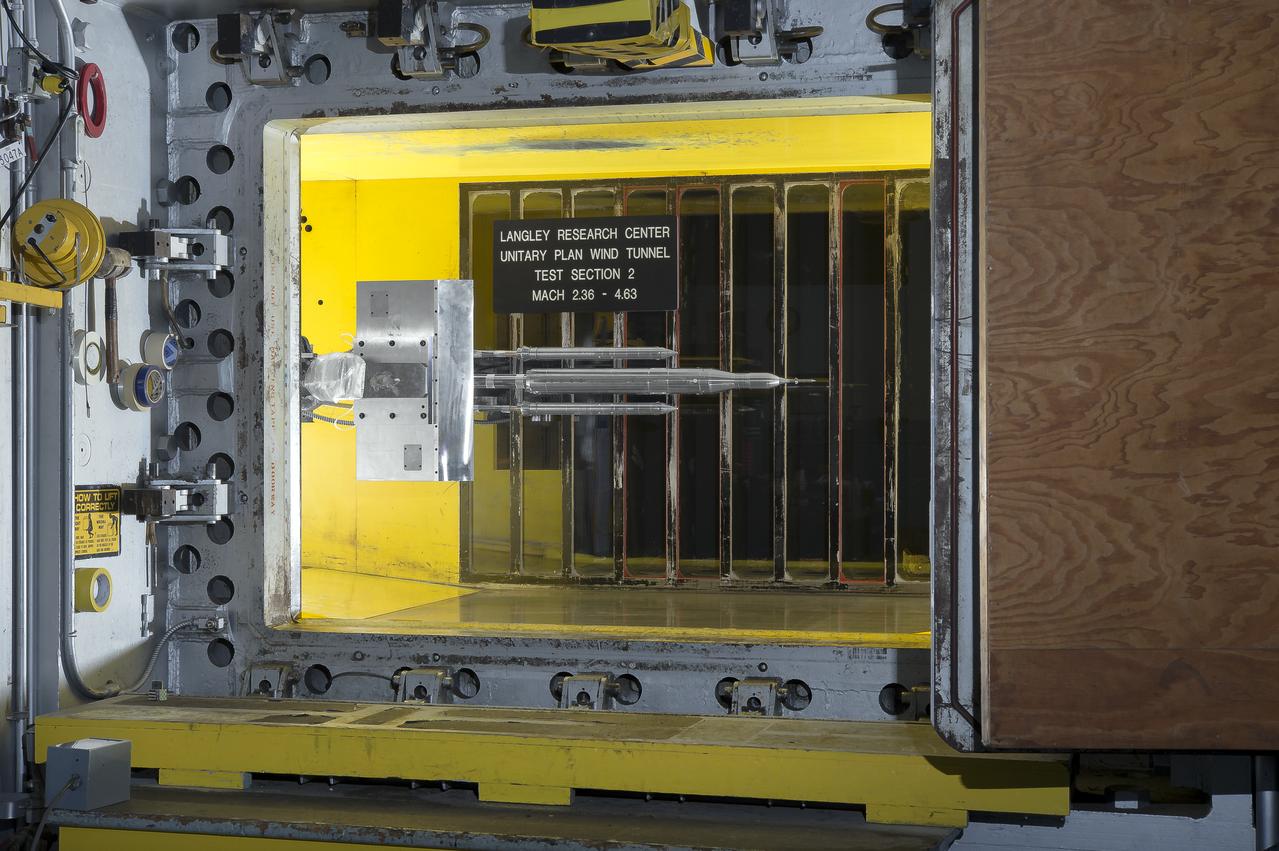
UPWT Test 1998 Continuous Data Sonic Boom Test. Sonic Boom Hardward Mounted in the Langley Unitary Plan wind Tunnel(UPWT). Conical survey probes, wedge probe, and wind tunnel wall boundary layer rake. Rectangular box with wedge front end is a transducer box to that held pressure transducer for the conical probes.
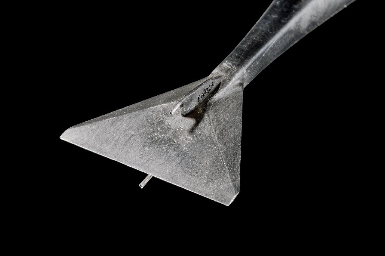
Two images left out of the original order in 2011 L numbers 3800-3810 2011. UPWT Test 1998 Continuous Data Sonic Boom Test. Sonic Boom Hardware Mounted in the Langley Unitary Plan wind Tunnel(UPWT). Conical survey probes, wedge probe, and wind tunnel wall boundary layer rake. Rectangular box with wedge front end is a transducer box to that held pressure transducer for the conical probes.
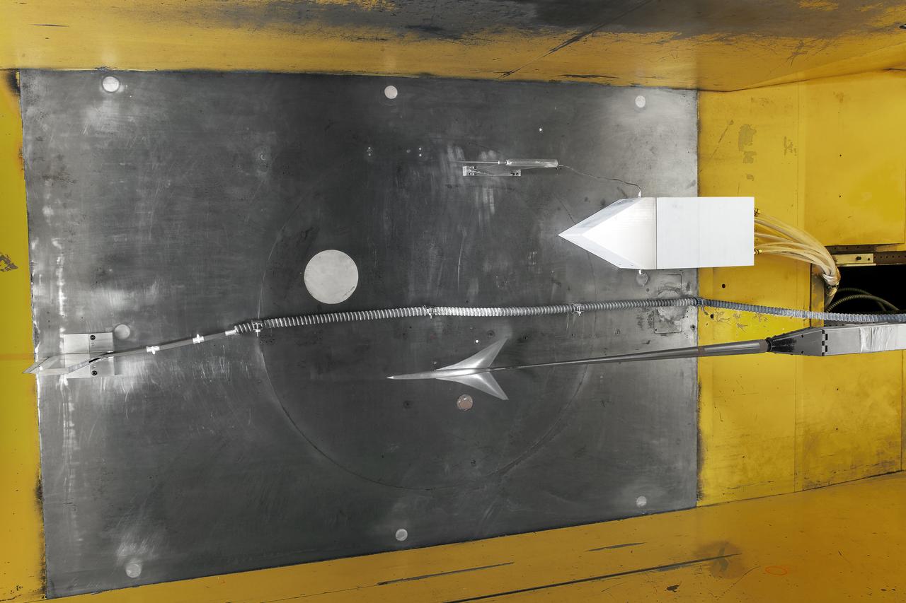
UPWT Test 1998 Continuous Data Sonic Boom Test. Sonic Boom Hardward Mounted in the Langley Unitary Plan wind Tunnel(UPWT). Conical survey probes, wedge probe, and wind tunnel wall boundary layer rake. Rectangular box with wedge front end is a transducer box to that held pressure transducer for the conical probes.
UPWT Test 1998 Continuous Data Sonic Boom Test. Sonic Boom Hardward Mounted in the Langley Unitary Plan wind Tunnel(UPWT). Conical survey probes, wedge probe, and wind tunnel wall boundary layer rake. Rectangular box with wedge front end is a transducer box to that held pressure transducer for the conical probes.
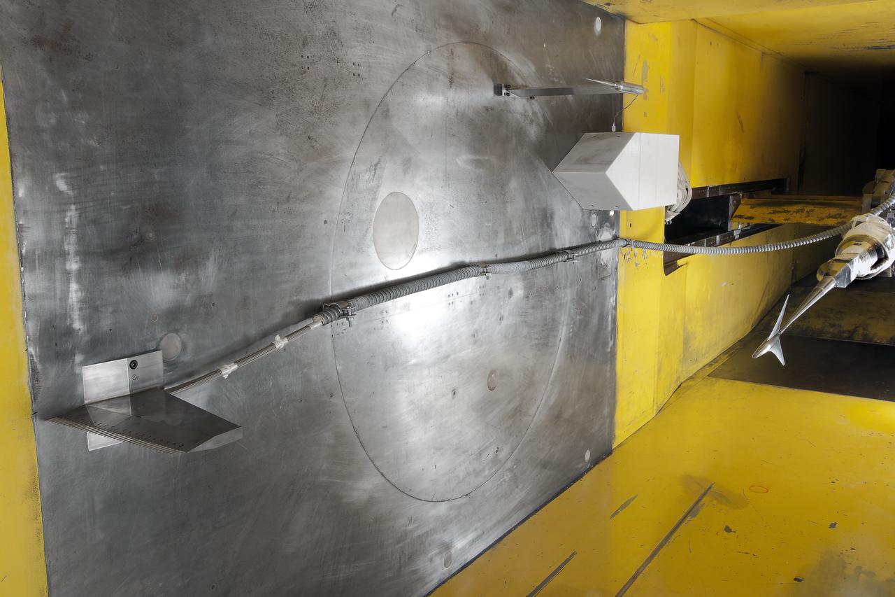
UPWT Test 1998 Continuous Data Sonic Boom Test. Sonic Boom Hardward Mounted in the Langley Unitary Plan wind Tunnel(UPWT). Conical survey probes, wedge probe, and wind tunnel wall boundary layer rake. Rectangular box with wedge front end is a transducer box to that held pressure transducer for the conical probes.
UPWT Test 1998 Continuous Data Sonic Boom Test. Sonic Boom Hardward Mounted in the Langley Unitary Plan wind Tunnel(UPWT). Conical survey probes, wedge probe, and wind tunnel wall boundary layer rake. Rectangular box with wedge front end is a transducer box to that held pressure transducer for the conical probes.
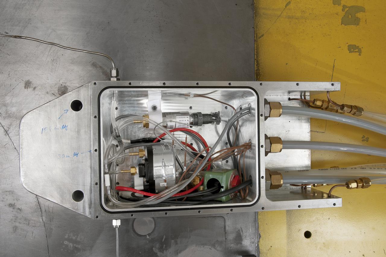
UPWT Test 1998 Continuous Data Sonic Boom Test. Sonic Boom Hardward Mounted in the Langley Unitary Plan wind Tunnel(UPWT). Conical survey probes, wedge probe, and wind tunnel wall boundary layer rake. Rectangular box with wedge front end is a transducer box to that held pressure transducer for the conical probes.

UPWT Test 1998 Continuous Data Sonic Boom Test. Sonic Boom Hardward Mounted in the Langley Unitary Plan wind Tunnel(UPWT). Conical survey probes, wedge probe, and wind tunnel wall boundary layer rake. Rectangular box with wedge front end is a transducer box to that held pressure transducer for the conical probes.
UPWT Test 1998 Continuous Data Sonic Boom Test. Sonic Boom Hardward Mounted in the Langley Unitary Plan wind Tunnel(UPWT). Conical survey probes, wedge probe, and wind tunnel wall boundary layer rake. Rectangular box with wedge front end is a transducer box to that held pressure transducer for the conical probes.
UPWT Test 1998 Continuous Data Sonic Boom Test. Sonic Boom Hardward Mounted in the Langley Unitary Plan wind Tunnel(UPWT). Conical survey probes, wedge probe, and wind tunnel wall boundary layer rake. Rectangular box with wedge front end is a transducer box to that held pressure transducer for the conical probes.
UPWT Test 1998 Continuous Data Sonic Boom Test. Sonic Boom Hardward Mounted in the Langley Unitary Plan wind Tunnel(UPWT). Conical survey probes, wedge probe, and wind tunnel wall boundary layer rake. Rectangular box with wedge front end is a transducer box to that held pressure transducer for the conical probes.
Two images left out of the original order in 2011 L numbers 3800-3810 2011. UPWT Test 1998 Continuous Data Sonic Boom Test. Sonic Boom Hardware Mounted in the Langley Unitary Plan wind Tunnel(UPWT). Conical survey probes, wedge probe, and wind tunnel wall boundary layer rake. Rectangular box with wedge front end is a transducer box to that held pressure transducer for the conical probes.
UPWT Test 1998 Continuous Data Sonic Boom Test. Sonic Boom Hardward Mounted in the Langley Unitary Plan wind Tunnel(UPWT). Conical survey probes, wedge probe, and wind tunnel wall boundary layer rake. Rectangular box with wedge front end is a transducer box to that held pressure transducer for the conical probes.
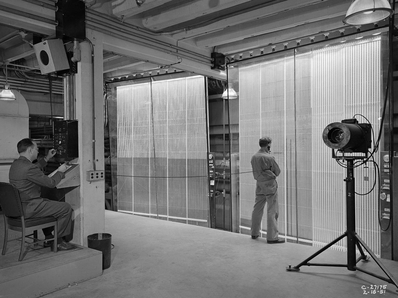
Analysts at the National Advisory Committee for Aeronautics (NACA) Lewis Flight Propulsion Laboratory take data readings from rows of manometers in the basement of the 8- by 6-Foot Supersonic Wind Tunnel. Manometers were mercury-filled glass tubes that indicated different pressure levels in the test section. Manometers look and function very similarly to thermometers. Pressure sensing instruments were installed on the test article inside the wind tunnel or other test facility. Each test could have dozens of such instruments installed and connected to a remotely located manometer tube. The mercury inside the manometer rose and fell with the pressure levels. The dark mercury can be seen at different levels within the tubes. Since the pressure readings were dynamic, it was necessary to note the levels at given points during the test. This was done using both female computers and photography. A camera is seen on a stand to the right in this photograph.
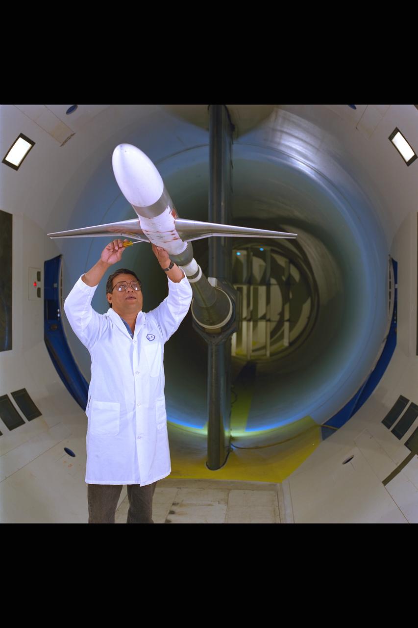
A model of the General Dynamics YF-16 Fighting Falcon in the test section of the 8- by 6-Foot Supersonic Wind Tunnel at the National Aeronautics and Space Administration (NASA) Lewis Research Center. The YF-16 was General Dynamics response to the military’s 1972 request for proposals to design a new 20,000-pound fighter jet with exceptional acceleration, turn rate, and range. The aircraft included innovative design elements to help pilots survive turns up to 9Gs, a new frameless bubble canopy, and a Pratt and Whitney 24,000-pound thrust F-100 engine. The YF-16 made its initial flight in February 1974, just six weeks before this photograph, at Edwards Air Force Base. Less than a year later, the Air Force ordered 650 of the aircraft, designated as F-16 Fighting Falcons. The March and April 1974 tests in the 8- by 6-foot tunnel analyzed the aircraft’s fixed-shroud ejector nozzle. The fixed-nozzle area limited drag, but also limited the nozzle’s internal performance. NASA researchers identified and assessed aerodynamic and aerodynamic-propulsion interaction uncertainties associated the prototype concept. YF-16 models were also tested extensively in the 11- by 11-Foot Transonic Wind Tunnel and 9- by 7-Foot Supersonic Wind Tunnel at Ames Research Center and the 12-Foot Pressure Wind Tunnel at Langley Research Center.
Stage Separation Test of the Space Launch System(SLS) in the Langley Unitary Plan Wind Tunnel (UPWT). The model used High Pressure air blown through the solid rocket boosters. (SRB) to simulate the booster separation motors (BSM) firing.
Stage Separation Test of the Space Launch System(SLS) in the Langley Unitary Plan Wind Tunnel (UPWT). The model used High Pressure air blown through the solid rocket boosters. (SRB) to simulate the booster separation motors (BSM) firing.
Stage Separation Test of the Space Launch System(SLS) in the Langley Unitary Plan Wind Tunnel (UPWT). The model used High Pressure air blown through the solid rocket boosters. (SRB) to simulate the booster separation motors (BSM) firing.
Stage Separation Test of the Space Launch System(SLS) in the Langley Unitary Plan Wind Tunnel (UPWT). The model used High Pressure air blown through the solid rocket boosters. (SRB) to simulate the booster separation motors (BSM) firing.
Stage Separation Test of the Space Launch System(SLS) in the Langley Unitary Plan Wind Tunnel (UPWT). The model used High Pressure air blown through the solid rocket boosters. (SRB) to simulate the booster separation motors (BSM) firing.
Stage Separation Test of the Space Launch System(SLS) in the Langley Unitary Plan Wind Tunnel (UPWT). The model used High Pressure air blown through the solid rocket boosters. (SRB) to simulate the booster separation motors (BSM) firing.
Stage Separation Test of the Space Launch System(SLS) in the Langley Unitary Plan Wind Tunnel (UPWT). The model used High Pressure air blown through the solid rocket boosters. (SRB) to simulate the booster separation motors (BSM) firing.