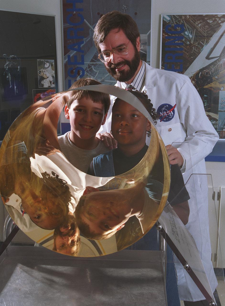
Through Marshall Space Flight Center (MSFC) Education Department, over 400 MSFC employees have volunteered to support educational program during regular work hours. Project LASER (Learning About Science, Engineering, and Research) provides support for mentor/tutor requests, education tours, classroom presentations, and curriculum development. This program is available to teachers and students living within commuting distance of the NASA/MSFC in Huntsville, Alabama (approximately 50-miles radius). This image depicts students viewing their reflections in an x-ray mirror with Marshall optic engineer Vince Huegele at the Discovery Laboratory, which is an onsite MSFC laboratory facility that provides hands-on educational workshop sessions for teachers and students learning activities.
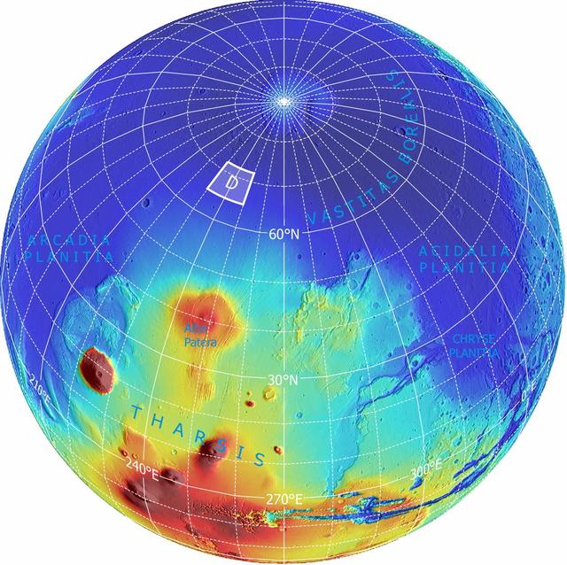
This is an orthographic projection with color-coded elevation contours and shaded relief based on data from the Mars Orbiter Laser Altimeter on NASA Mars Global Surveyor orbiter.

Howard University graduate student LaRay Hare discusses his CubeRover project in the Laser Spectroscopy Laboratory with NASA astronaut Jessica Watkins, Friday, March 31, 2023, at Howard University in Washington. Photo Credit: (NASA/Aubrey Gemignani)
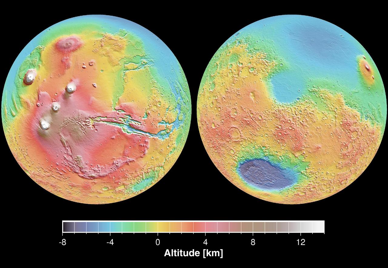
These maps are global false-color topographic views of Mars at different orientations from NASA Mars Orbiter Laser Altimeter MOLA. The maps are orthographic projections that contain over 200,000,000 points and about 5,000,000 altimetric crossovers.
The SELENE Optics project was designed to send powerful laser beams into space to repower satellites and to recharge their batteries, as well as sending laser beams to the moon for the same purpose instead of relying on solar power. This project also was intended to be used for repowering extended space flights.
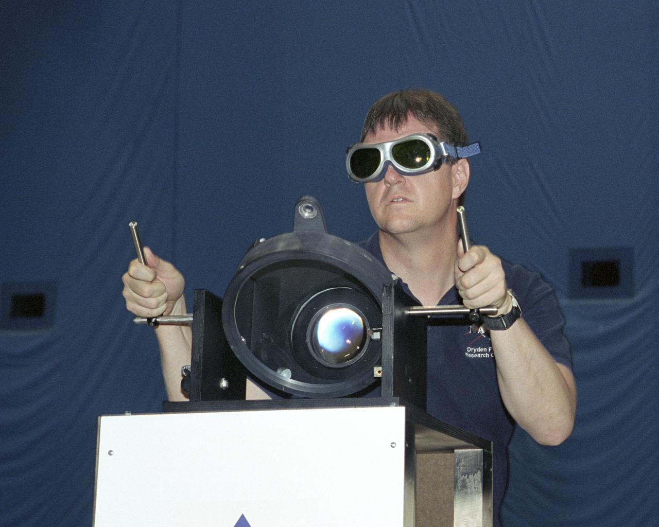
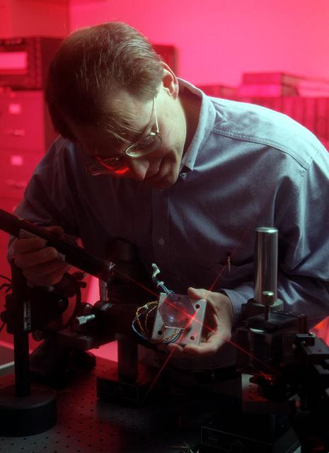
NASA Dryden project engineer Dave Bushman carefully aims the optics of a laser device at a solar cell panel on a model aircraft during the first flight demonstration of an aircraft powered by laser light.
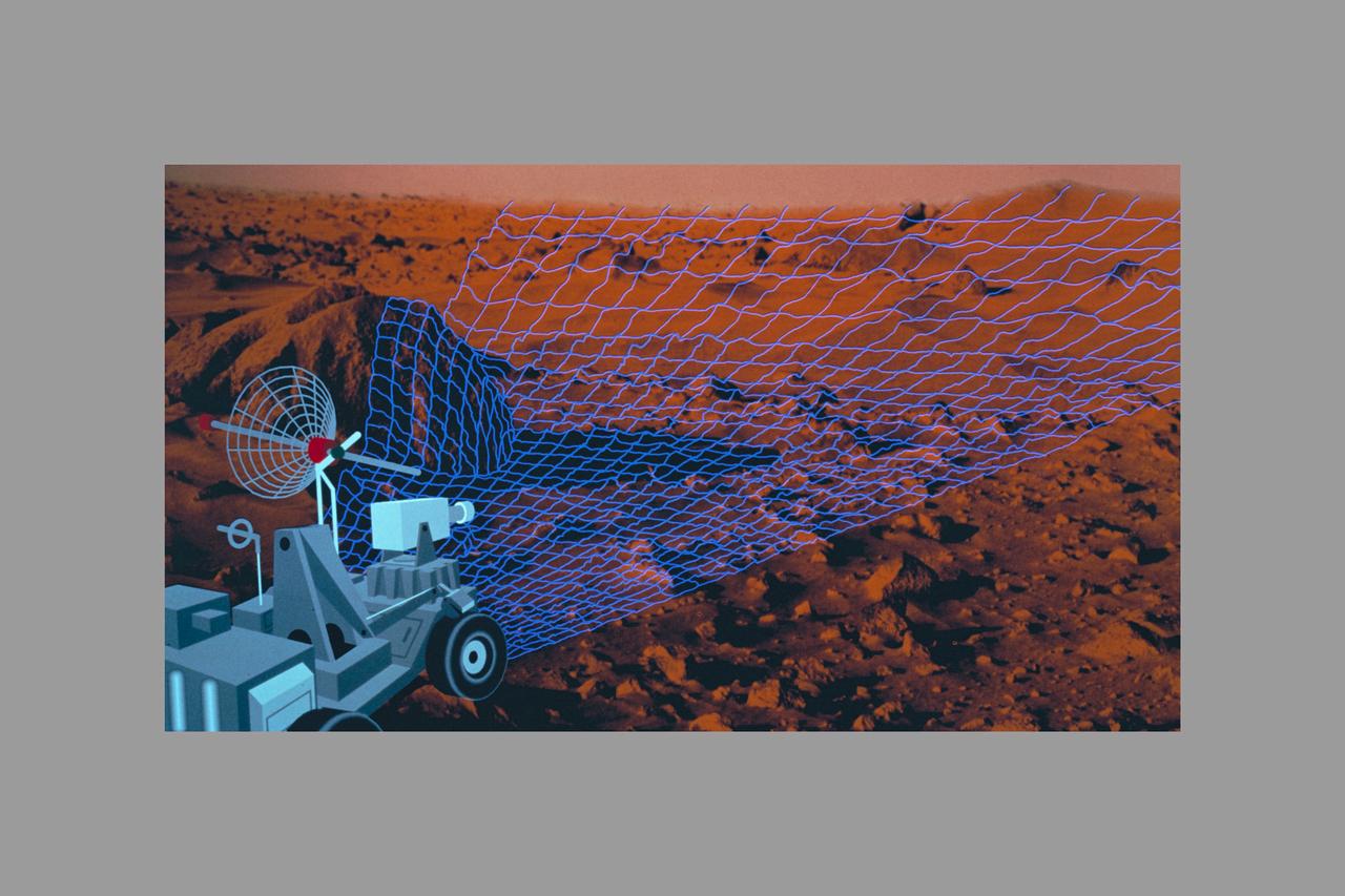
Autonomous Perception Vision project - Intelligent Systems - Machine Vision, Fusing Photonics and A.I. - Fiber-Optic Probe for Laser Velocimetry (Mars)
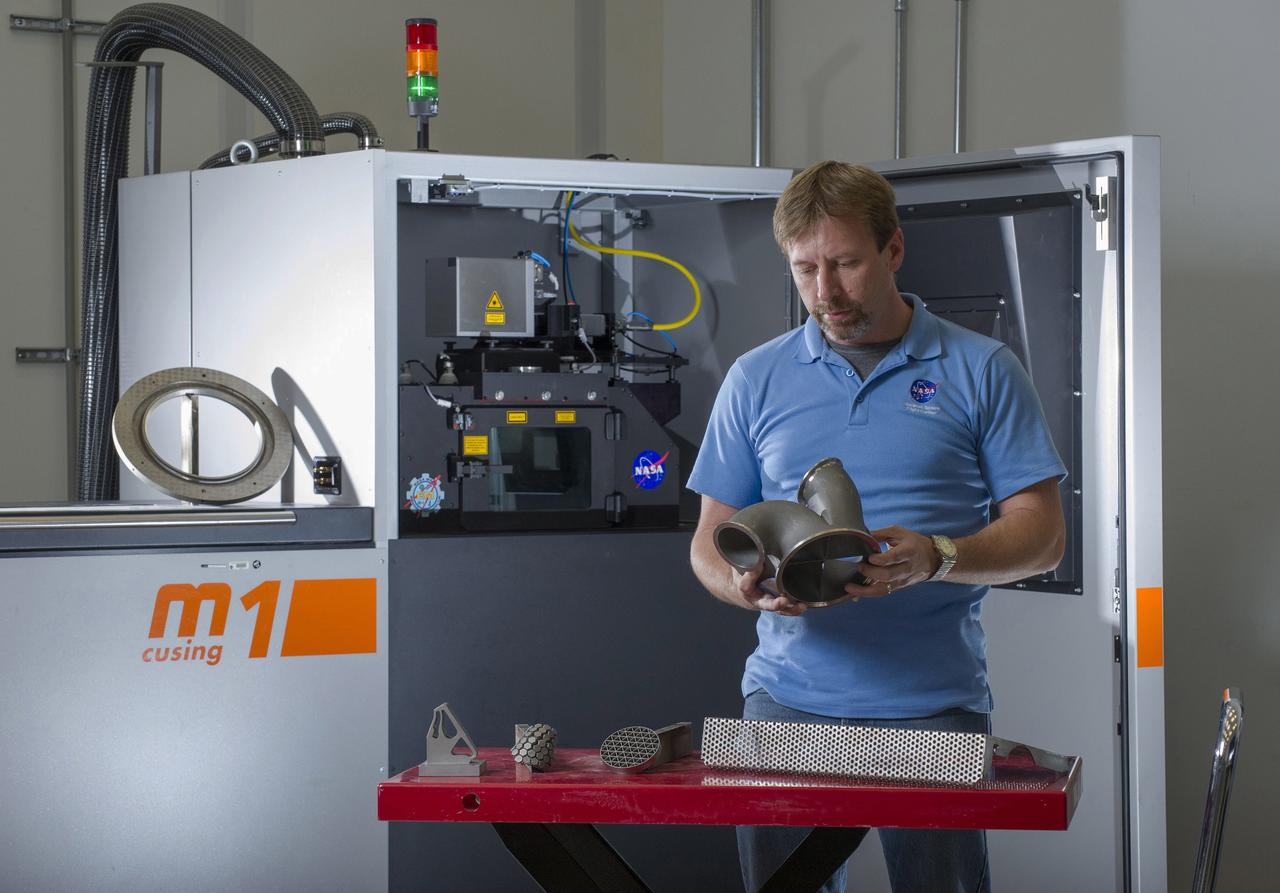
KEN COOPER, TEAM LEAD OF MSFC’S ADVANCED MANUFACTURING TEAM, WITH NICKEL ALLOY 718 PARTS FABRICATED USING THE M1 SELECTIVE LASER MELTING SYSTEM. THE M1 MACHINE IS DEDICATED TO BUILDING QUALIFICATION SAMPLES AND HARDWARE DEMONSTRATORS FOR THE RS25 ENGINE PROJECT.

Howard University graduate student LaRay Hare discusses his CubeRover project in the Laser Spectroscopy Laboratory with NASA astronaut Jessica Watkins, Friday, March 31, 2023, at Howard University in Washington. Photo Credit: (NASA/Aubrey Gemignani)

Particle-image velocimetry (PIV) is performed on the upper surface of a pitching airfoil in the NASA Glenn Icing Research Tunnel. PIV is a laser-based flow velocity measurement technique used widely in wind tunnels. These experiments were conducted as part of a research project focused on enhancing rotorcraft speed, efficiency and maneuverability by suppressing dynamic stall.
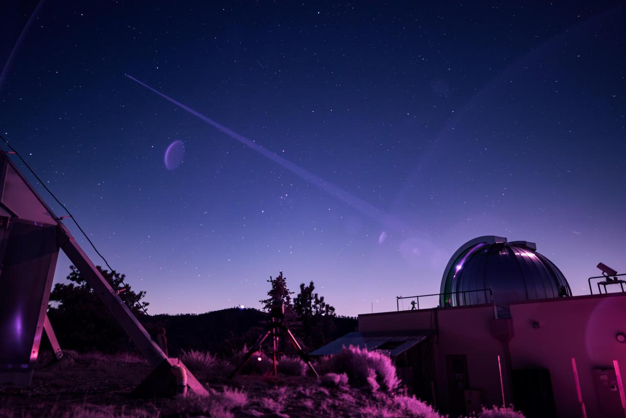
In this infrared photograph, the Optical Communications Telescope Laboratory (OCTL) at NASA Jet Propulsion Laboratory's Table Mountain Facility near Wrightwood, California, beams its eight-laser beacon (at a total power of 1.4 kilowatts) to the Deep Space Optical Communications (DSOC) flight laser transceiver aboard NASA's Psyche spacecraft. The photo was taken on June 2, 2025, when Psyche was about 143 million miles (230 million kilometers) from Earth. The faint purple crescent just left of center and near the laser beam is a lens flare caused by a bright light (out of frame) reflecting inside the camera lens. As the experiment's ground laser transmitter, OCTL transmits at an infrared wavelength of 1,064 nanometers from its 3.3-foot-aperture (1-meter) telescope. The telescope can also receive faint infrared photons (at a wavelength of 1,550 nanometers) from the 4-watt flight laser transceiver on Psyche. Neither infrared wavelength is easily absorbed or scattered by Earth's atmosphere, making both ideal for deep space optical communications. To receive the most distant signals from Psyche, the project enlisted the powerful 200-inch-aperture (5-meter) Hale Telescope at Caltech's Palomar Observatory in San Diego County, California, as its primary downlink station, which provided adequate light-collecting area to capture the faintest photons. Those photons were then directed to a cryogenically cooled superconducting high-efficiency detector array at the observatory where the information encoded in the photons could be processed. Managed by JPL, DSOC was designed to demonstrate that data encoded in laser photons could be reliably transmitted, received, and then decoded after traveling millions of miles from Earth out to Mars distances. Nearly two years after launching aboard the agency's Psyche mission in 2023, the demonstration completed its 65th and final "pass" on Sept. 2, 2025, sending a laser signal to Psyche and receiving the return signal from 218 million miles (350 million kilometers) away. https://photojournal.jpl.nasa.gov/catalog/PIA26661
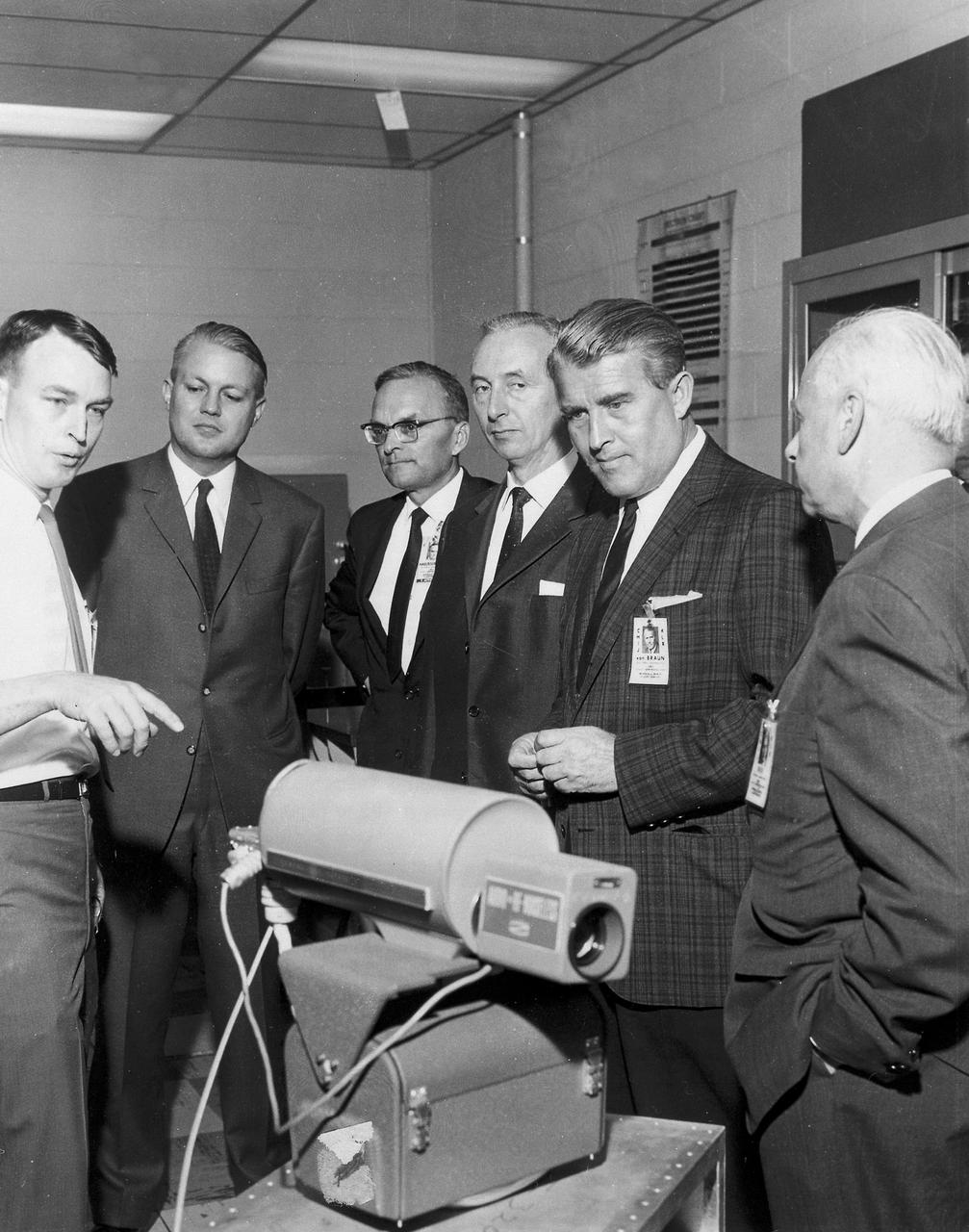
Dr. Joseph Randall, a laser expert at Marshall Space Flight Center (MSFC), explains one of the projects he is working on to a group composed of Federal Republic of Germany and MSFC officials. From left are: Dr. Randall; Minister for Scientific Research of Federal Republic of Germany, Dr. Gerhard Stolenberg; Director of MSFC Astrionics Lab, Dr. Walter Haeusserman; Head of Space Research Federal Republic of Germany, Max Mayer; MSFC Director Dr. von Braun; MSFC Deputy Director Dr. Elberhard Rees.

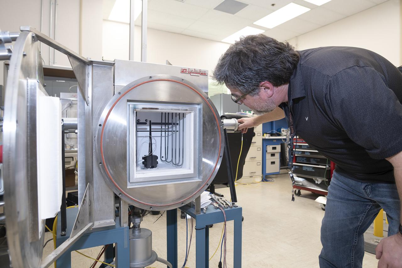
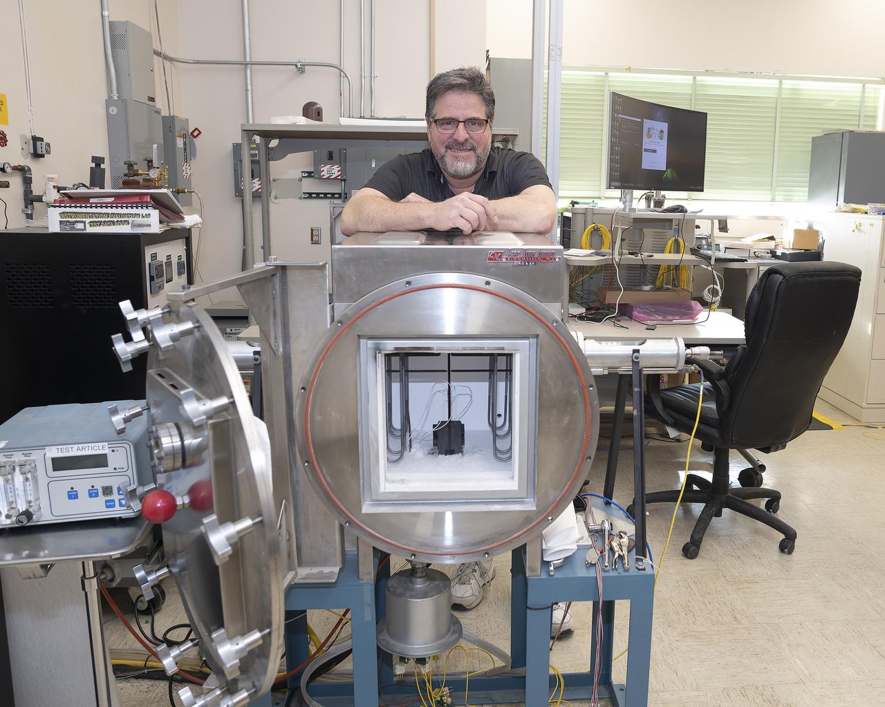
Dr. Jan Rogers, project scientist for the Electrostatic Levitator (ESL) at NASA's Marshall Space Flight Center(MSFC). The ESL uses static electricity to suspend an obejct (about 2-3 mm in diameter) inside a vacuum chamber while a laser heats the sample until it melts. This lets scientists record a wide range of physical properties without the sample contacting the container or any instruments, conditions that would alter the readings. The Electrostatic Levitator is one of several tools used in NASA's microgravity materials sciences program.
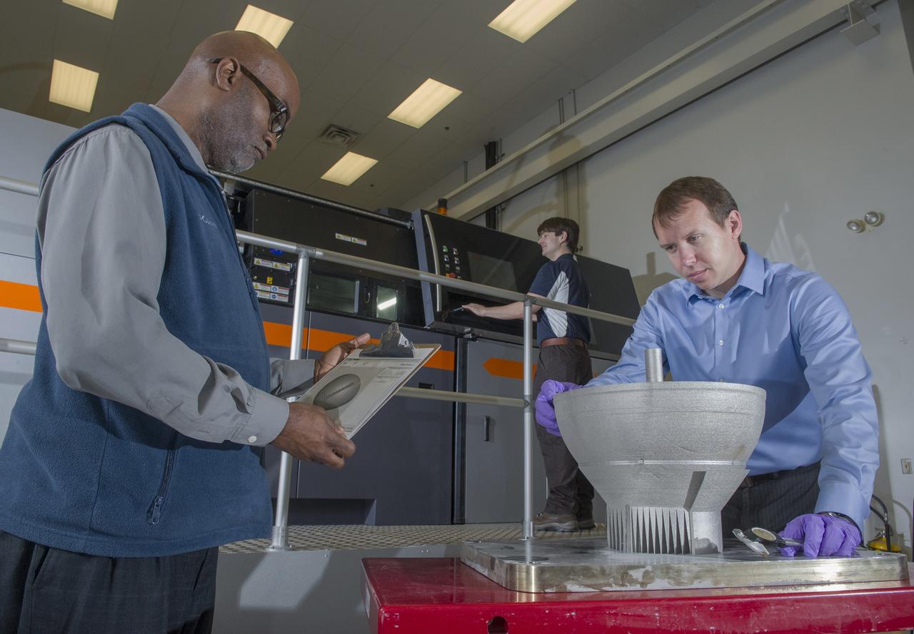
JOHNNIE CLARK, BRIAN WEST, AND ZACK JONES OF MSFC’S ADVANCED MANUFACTURING TEAM, WITH MSFC’S XLINE SELECTIVE LASER MELTING SYSTEM. CURRENTLY ONE OF THE LARGEST METAL 3D PRINTERS, THE XLINE AT MARSHALL IS BEING USED TO DEVELOP AND CERTIFY NICKEL ALLOY 718 MATERIAL PROPERTIES AND LARGE MANUFACTURING TECH DEMOS FOR THE RS25 ENGINE AND THE COMMERCIAL CREWED VEHICLE PROJECTS.

This infrared photograph shows the uplink laser beacon for NASA's Deep Space Optical Communications (DSOC) experiment beaming into the night sky from the Optical Communications Telescope Laboratory (OCTL) at NASA Jet Propulsion Laboratory's Table Mountain Facility near Wrightwood, California. Attached to the agency's Psyche spacecraft, the DSOC flight laser transceiver can receive and send data from Earth in encoded photons. As the experiment's ground laser transmitter, OCTL transmits at an infrared wavelength of 1,064 nanometers from its 3.3-foot-aperture (1-meter) telescope. The telescope can also receive faint infrared photons (at a wavelength of 1,550 nanometers) from the 4-watt flight laser transceiver on Psyche. Neither infrared wavelength is easily absorbed or scattered by Earth's atmosphere, making both ideal for deep space optical communications. To receive the most distant signals from Psyche, the project enlisted the powerful 200-inch-aperture (5-meter) Hale Telescope at Caltech's Palomar Observatory in San Diego County, California, as its primary downlink station, which provided adequate light-collecting area to capture the faintest photons. Those photons were then directed to a cryogenically cooled superconducting high-efficiency detector array at the observatory where the information encoded in the photons could be processed. Managed by JPL, DSOC was designed to demonstrate that data encoded in laser photons could be reliably transmitted, received, and then decoded after traveling millions of miles from Earth out to Mars distances. Nearly two years after launching aboard the agency's Psyche mission in 2023, the demonstration completed its 65th and final "pass" on Sept. 2, 2025, sending a laser signal to Psyche and receiving the return signal from 218 million miles (350 million kilometers) away. https://photojournal.jpl.nasa.gov/catalog/PIA26662
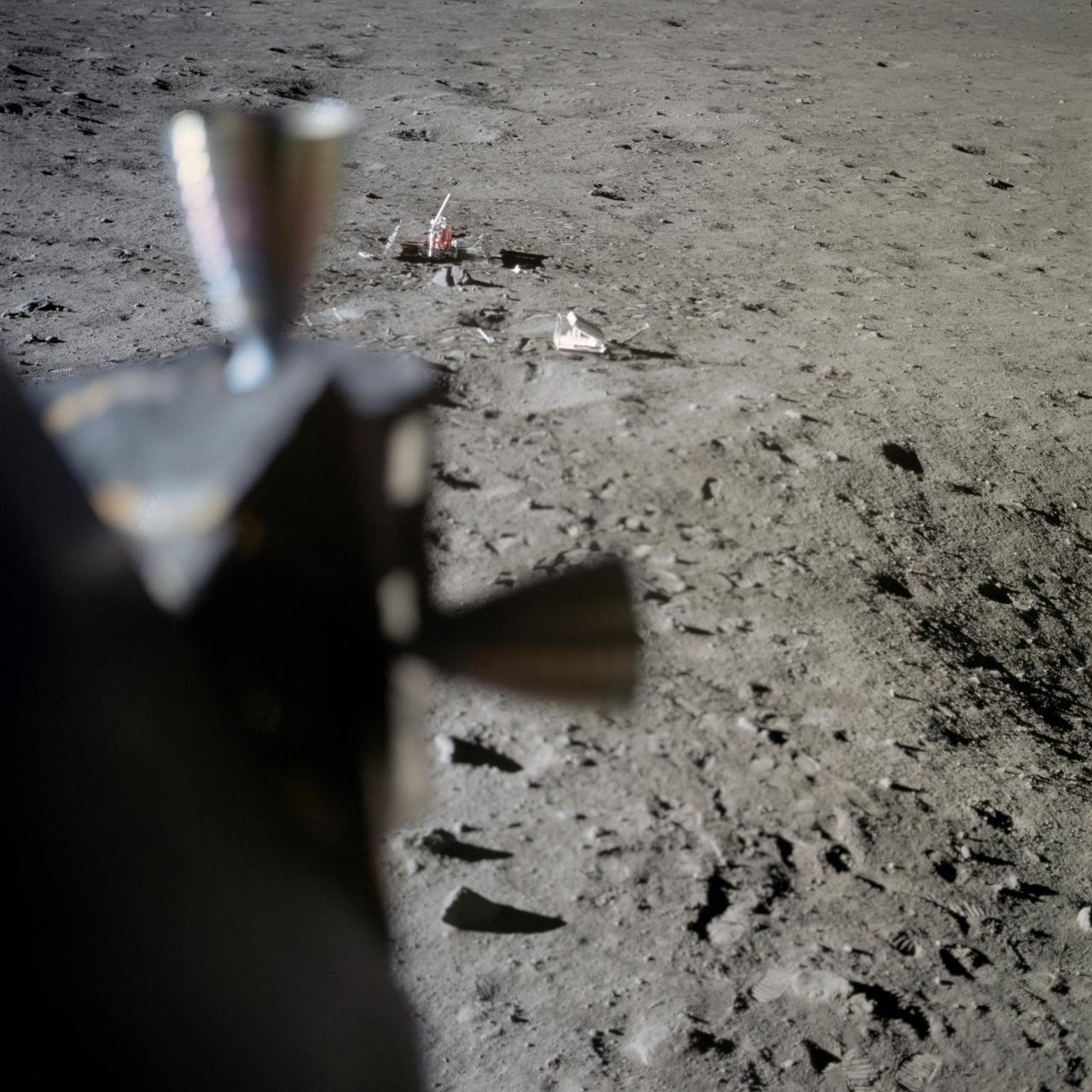
AS11-37-5551 (20 July 1969) --- Two components of the Early Apollo Scientific Experiments Package (EASEP) are seen deployed on the lunar surface in this view photographed from inside the Lunar Module (LM). In the far background is the Passive Seismic Experiment Package (PSEP); and to the right and closer to the camera is the Laser Ranging Retro-Reflector (LR-3). The footprints of Apollo 11 astronauts Neil A. Armstrong and Edwin E. Aldrin Jr. are very distinct in the lunar soil.
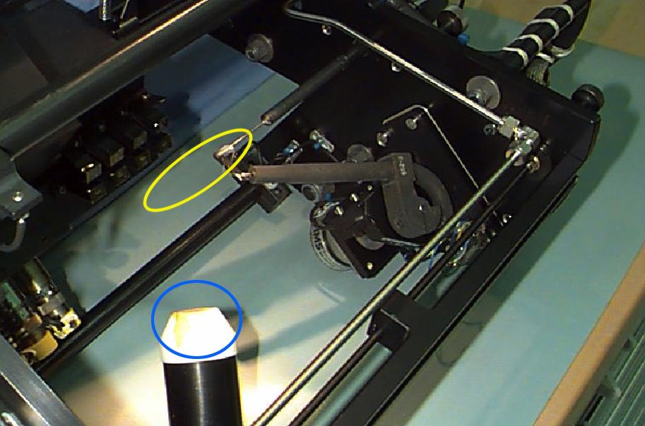
Interior of the Equipment Module for the Laminar Soot Processes (LSP-2) experiment that fly in the STS-107 Research 1 mission in 2002 (LSP-1 flew on Microgravity Sciences Lab-1 mission in 1997). The principal investigator is Dr. Gerard Faeth of the University of Michigan. LSP uses a small jet burner (yellow ellipse), similar to a classroom butane lighter, that produces flames up to 60 mm (2.3 in) long. Measurements include color TV cameras and a radiometer or heat sensor (blue circle), and laser images whose darkness indicates the quantity of soot produced in the flame. Glenn Research in Cleveland, OH, manages the project.
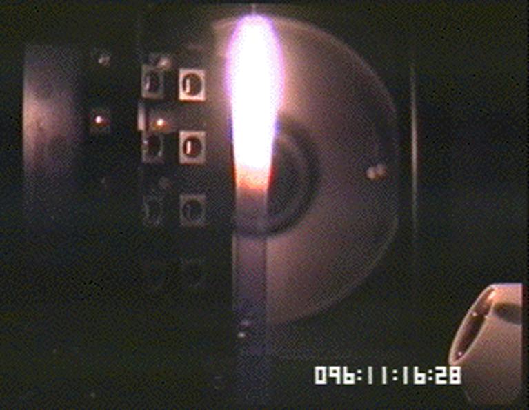
The Laminar Soot Processes (LSP) experiment under way during the Microgravity Sciences Lab-1 mission in 1997. LSP-2 will fly in the STS-107 Research 1 mission in 2001. The principal investigator is Dr. Gerard Faeth of the University of Michigan. LSP uses a small jet burner, similar to a classroom butane lighter, that produces flames up to 60 mm (2.3 in) long. Measurements include color TV cameras and a temperature sensor, and laser images whose darkness indicates the quantity of soot produced in the flame. Glenn Research in Cleveland, OH, manages the project.
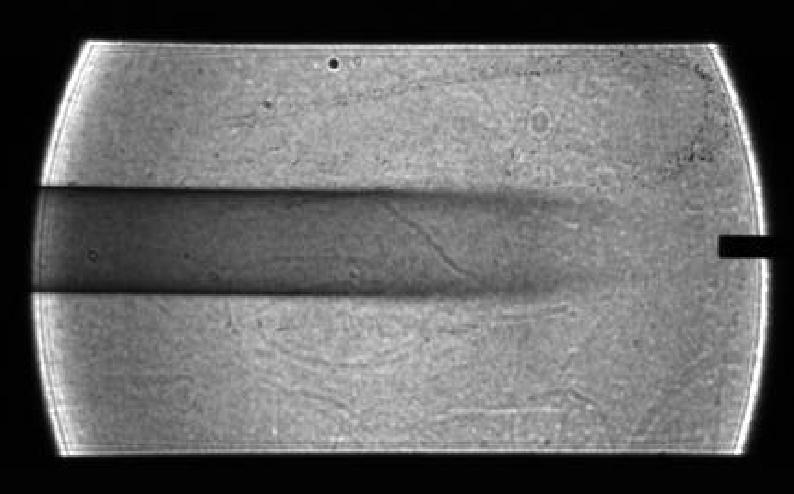
Image of soot (smoke) plume made for the Laminar Soot Processes (LSP) experiment during the Microgravity Sciences Lab-1 mission in 1997. LSP-2 will fly in the STS-107 Research 1 mission in 2002. The principal investigator is Dr. Gerard Faeth of the University of Michigan. LSP uses a small jet burner, similar to a classroom butane lighter, that produces flames up to 60 mm (2.3 in) long. Measurements include color TV cameras and a temperature sensor, and laser images whose darkness indicates the quantity of soot produced in the flame. Glenn Research in Cleveland, OH, manages the project.

STS052-S-001 (July 1992) --- The insignia, designed by the STS-52 crew members, features a large gold star to symbolize the crew's mission on the frontiers of space. A gold star is often used to symbolize the frontier period of the American West. The red star in the shape of the Greek letter lambda represents both the laser measurements to be taken from the Laser Geodynamic Satellite (LAGEOS II) and the Lambda Point Experiment, which is part of the United States Microgravity Payload (USMP-1). The LAGEOS II is a joint Italian\United States satellite project intended to further our understanding of global plate tectonics. The USMP-1 is a microgravity facility which has French and United States experiments designed to test the theory of cooperative phase transitions and to study the solid\liquid interface of a metallic alloy in the low gravity environment. The Remote Manipulator System (RMS) and maple leaf are emblematic of the Canadian payload specialist who will conduct a series of Canadian flight experiments (CANEX-2), including the Space Vision System test. The NASA insignia design for space shuttle flights is reserved for use by the astronauts and for other official use as the NASA Administrator may authorize. Public availability has been approved only in the form of illustrations by the various news media. When and if there is any change in this policy, which we do not anticipate, it will be publicly announced. Photo credit: NASA
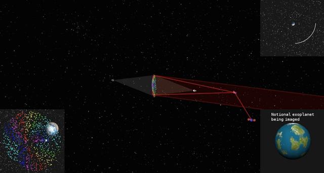
This simulated image shows how a cloud of glitter in geostationary orbit would be illuminated and controlled by two laser beams. As the cloud orbits Earth, grains scatter the sun's light at different angles like many tiny prisms, similar to how rainbows are produced from light being dispersed by water droplets. That is why the project concept is called "Orbiting Rainbows." The cloud functions like a reflective surface, allowing the exoplanet (displayed in the bottom right) to be imaged. The orbit path is shown in the top right. On the bottom left, Earth's image is seen behind the cloud. To image an exoplanet, the cloud would need to have a diameter of nearly 98 feet (30 meters). This simulation confines the cloud to a 3.3 x 3.3 x 3.3 foot volume (1 x 1 x 1 meter volume) to simplify the computations. The elements of the orbiting telescope are not to scale. Orbiting Rainbows is currently in Phase II development through the NASA Innovative Advanced Concepts (NIAC) Program. It was one of five technology proposals chosen for continued study in 2014. In the current phase, Orbiting Rainbows researchers are conducting small-scale ground experiments to demonstrate how granular materials can be manipulated using lasers and simulations of how the imaging system would behave in orbit. http://photojournal.jpl.nasa.gov/catalog/PIA19318
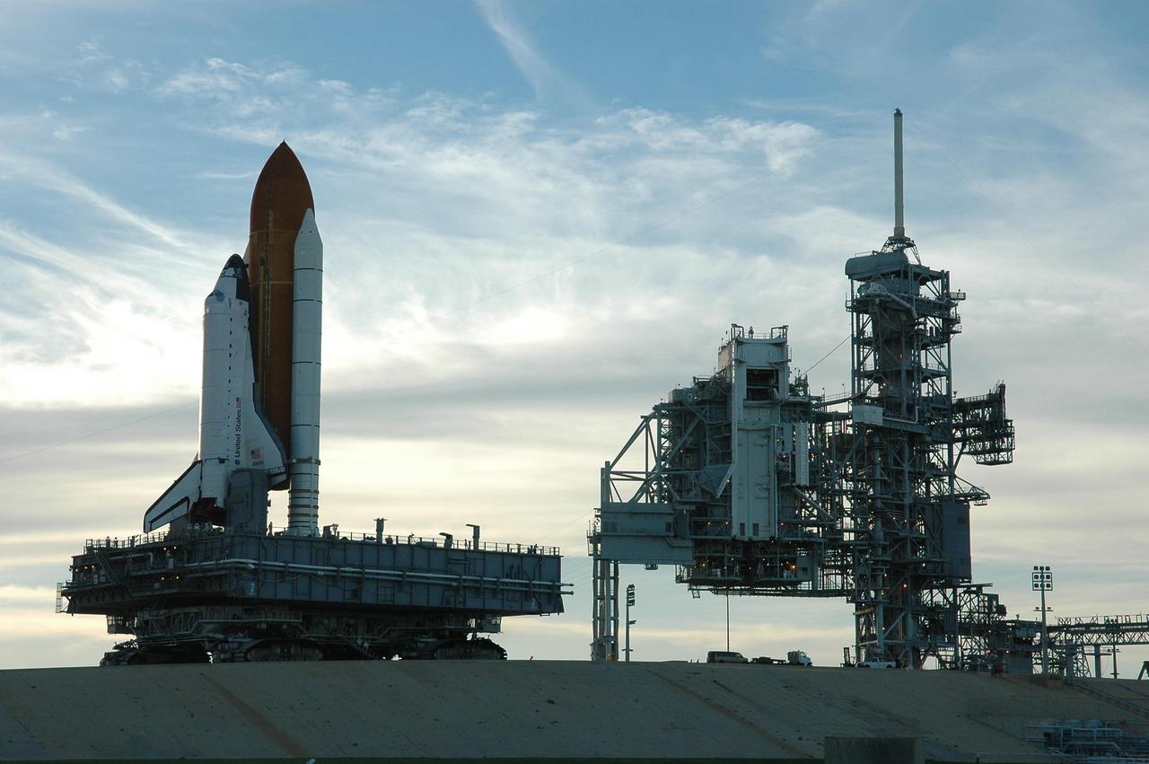
KENNEDY SPACE CENTER, FLA. - Space Shuttle Atlantis rolls up the ramp to Launch Pad 39B atop the crawler-transporter. The crawler has a leveling system designed to keep the top of the space shuttle vertical while negotiating the 5-percent grade leading to the top of the launch pad. Also, a laser docking system provides almost pinpoint accuracy when the crawler and mobile launcher platform are positioned at the launch pad. At right are the open rotating service structure and the fixed service structure topped by the 80-foot lightning mast. The shuttle had been moved off the launch pad due to concerns about the impact of Tropical Storm Ernesto, expected within 24 hours. The forecast of lesser winds expected from Ernesto and its projected direction convinced Launch Integration Manager LeRoy Cain and Shuttle Launch Director Mike Leinbach to return the shuttle to the launch pad. Photo credit: NASA/Kim Shiflett
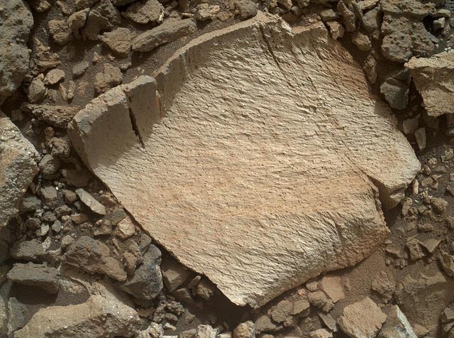
A rock fragment dubbed "Lamoose" is shown in this picture taken by the Mars Hand Lens Imager (MAHLI) on NASA's Curiosity rover. Like other nearby rocks in a portion of the "Marias Pass" area of Mt. Sharp, Mars, it has unusually high concentrations of silica. The high silica was first detected in the area by the Chemistry & Camera (ChemCam) laser spectrometer. This rock was targeted for follow-up study by the MAHLI and the arm-mounted Alpha Particle X-ray Spectrometer (APXS). Silica is a rock-forming compound containing silicon and oxygen, commonly found on Earth as quartz. High levels of silica could indicate ideal conditions for preserving ancient organic material, if present, so the science team wants to take a closer look. The rock is about 4 inches (10 centimeters) across. It is fine-grained, perhaps finely layered, and etched by the wind. The image was taken on the 1,041st Martian day, or sol, of the mission (July 11, 2015). MAHLI was built by Malin Space Science Systems, San Diego. NASA's Jet Propulsion Laboratory, a division of the California Institute of Technology in Pasadena, manages the Mars Science Laboratory Project for the NASA Science Mission Directorate, Washington. JPL designed and built the project's Curiosity rover. http://photojournal.jpl.nasa.gov/catalog/PIA19828

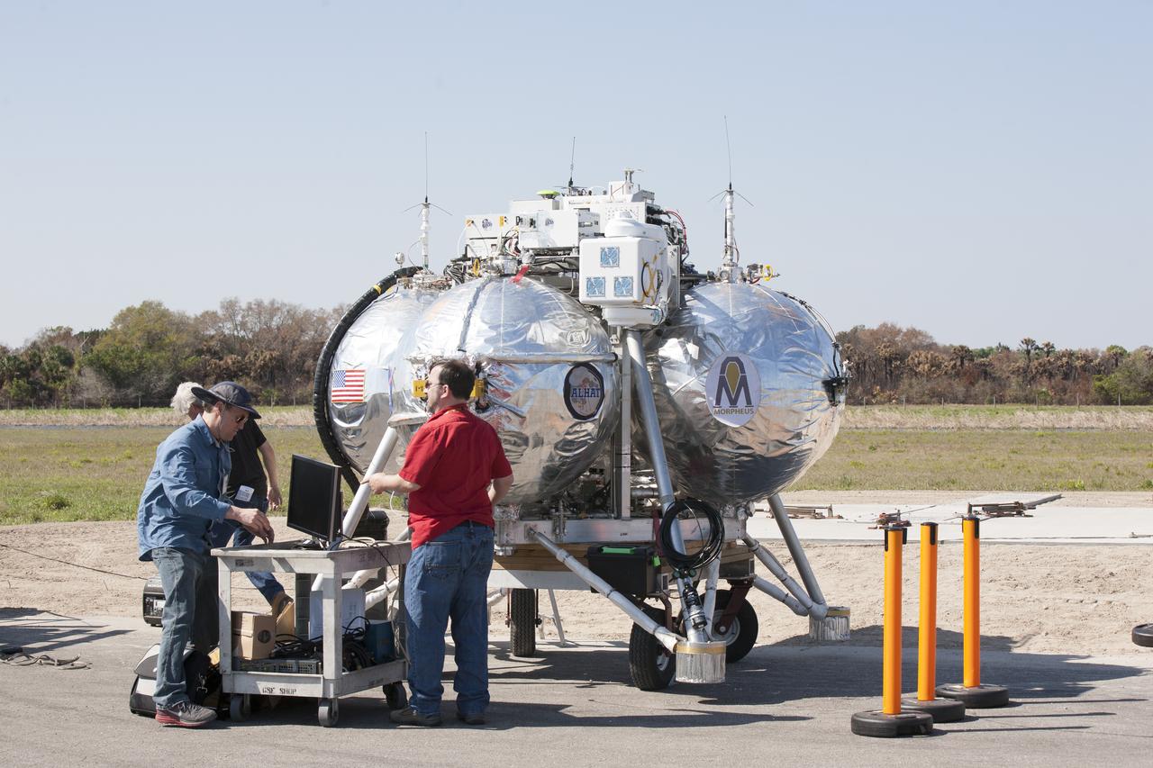
CAPE CANAVERAL, Fla. – Engineers and technicians prepare the Project Morpheus prototype lander for an automated landing and hazard avoidance technology, or ALHAT, and laser test at a new launch site at the north end of the Shuttle Landing Facility at NASA’s Kennedy Space Center in Florida. The launch pad was moved to a different location at the landing facility to support the next phase of flight testing. The seventh free flight test of Morpheus occurred on March 11. The 83-second test began at 3:41 p.m. EDT with the Morpheus lander launching from the ground over a flame trench and ascending to 580 feet. Morpheus then flew its fastest downrange trek at 30 mph, travelling farther than before, 837 feet. The lander performed a 42-foot divert to emulate a hazard avoidance maneuver before descending and touching down on Landing Site 2, at the northern landing pad inside the ALHAT hazard field. Morpheus landed within one foot of its intended target. Project Morpheus tests NASA’s ALHAT and an engine that runs on liquid oxygen and methane, or green propellants, into a fully-operational lander that could deliver cargo to other planetary surfaces. The landing facility provides the lander with the kind of field necessary for realistic testing, complete with rocks, craters and hazards to avoid. Morpheus’ ALHAT payload allows it to navigate to clear landing sites amidst rocks, craters and other hazards during its descent. Project Morpheus is being managed under the Advanced Exploration Systems, or AES, Division in NASA’s Human Exploration and Operations Mission Directorate. The efforts in AES pioneer new approaches for rapidly developing prototype systems, demonstrating key capabilities and validating operational concepts for future human missions beyond Earth orbit. For more information on Project Morpheus, visit http://morpheuslander.jsc.nasa.gov/. Photo credit: NASA/Kim Shiflett
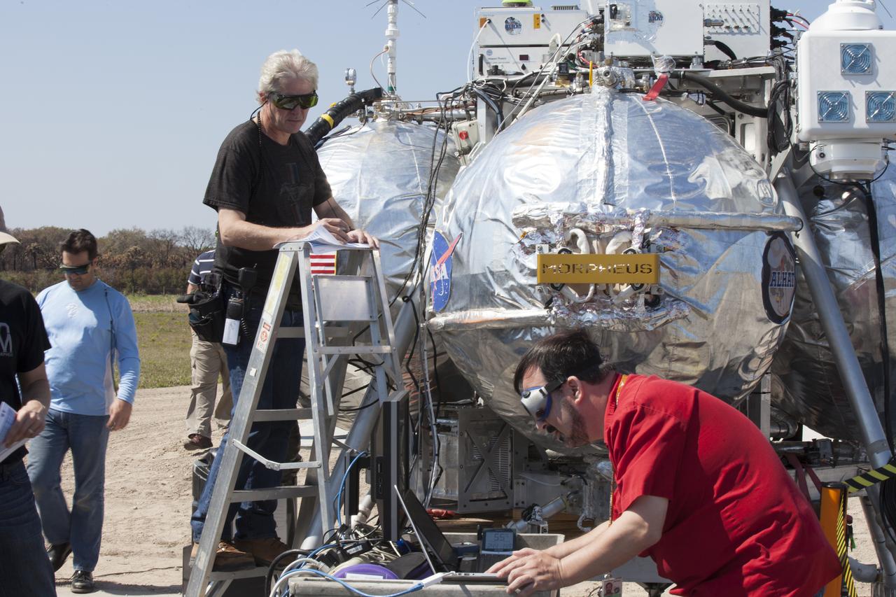
CAPE CANAVERAL, Fla. – Engineers run an automated landing and hazard avoidance technology, or ALHAT, and laser test on the Project Morpheus prototype lander at a new launch site at the north end of the Shuttle Landing Facility at NASA’s Kennedy Space Center in Florida. The launch pad was moved to a different location at the landing facility to support the next phase of flight testing. The seventh free flight test of Morpheus occurred on March 11. The 83-second test began at 3:41 p.m. EDT with the Morpheus lander launching from the ground over a flame trench and ascending to 580 feet. Morpheus then flew its fastest downrange trek at 30 mph, travelling farther than before, 837 feet. The lander performed a 42-foot divert to emulate a hazard avoidance maneuver before descending and touching down on Landing Site 2, at the northern landing pad inside the ALHAT hazard field. Morpheus landed within one foot of its intended target. Project Morpheus tests NASA’s ALHAT and an engine that runs on liquid oxygen and methane, or green propellants, into a fully-operational lander that could deliver cargo to other planetary surfaces. The landing facility provides the lander with the kind of field necessary for realistic testing, complete with rocks, craters and hazards to avoid. Morpheus’ ALHAT payload allows it to navigate to clear landing sites amidst rocks, craters and other hazards during its descent. Project Morpheus is being managed under the Advanced Exploration Systems, or AES, Division in NASA’s Human Exploration and Operations Mission Directorate. The efforts in AES pioneer new approaches for rapidly developing prototype systems, demonstrating key capabilities and validating operational concepts for future human missions beyond Earth orbit. For more information on Project Morpheus, visit http://morpheuslander.jsc.nasa.gov/. Photo credit: NASA/Kim Shiflett
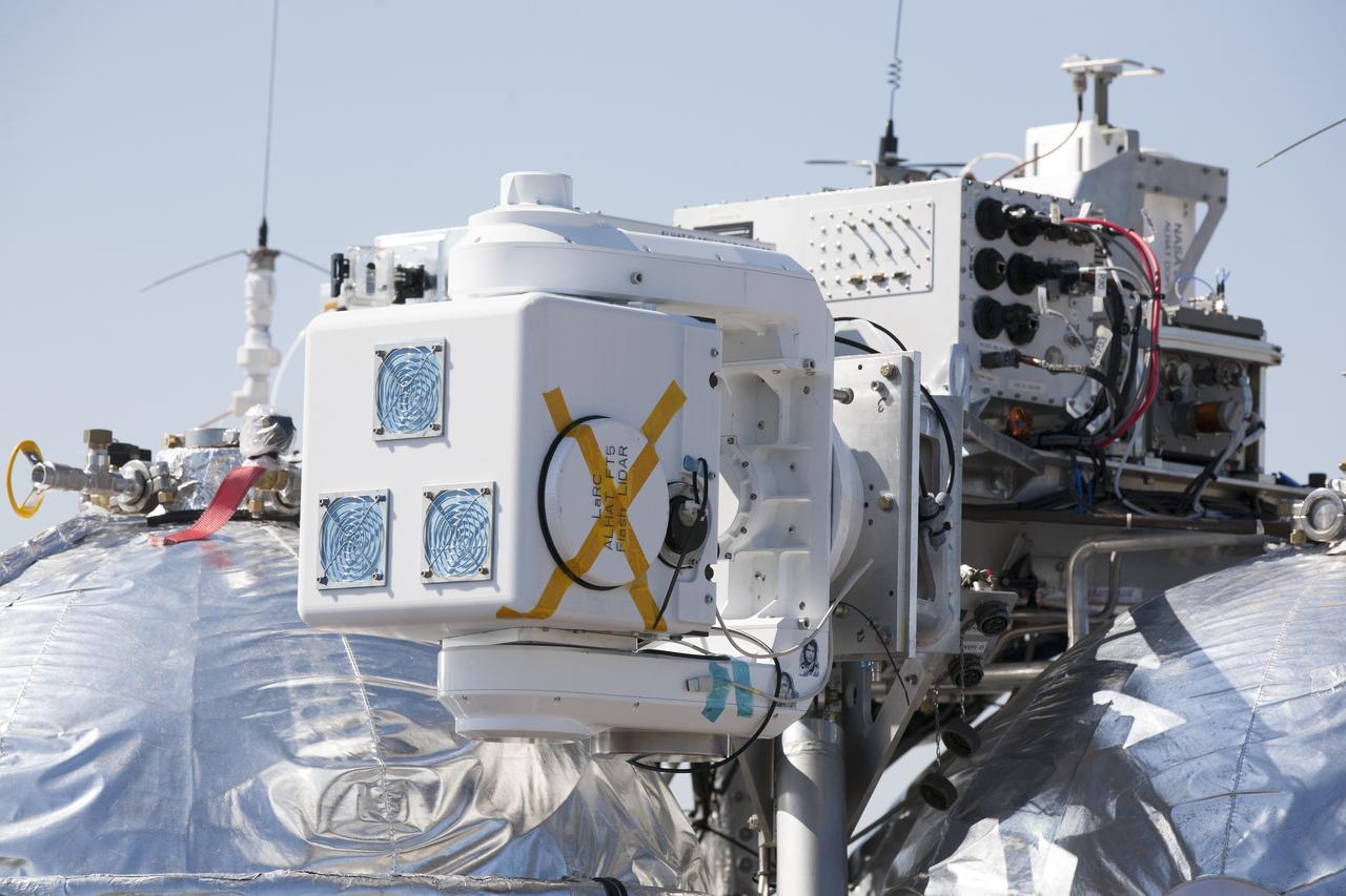
CAPE CANAVERAL, Fla. – Engineers run an automated landing and hazard avoidance technology, or ALHAT, and laser test on the Project Morpheus prototype lander at a new launch site at the north end of the Shuttle Landing Facility at NASA’s Kennedy Space Center in Florida. The launch pad was moved to a different location at the landing facility to support the next phase of flight testing. The seventh free flight test of Morpheus occurred on March 11. The 83-second test began at 3:41 p.m. EDT with the Morpheus lander launching from the ground over a flame trench and ascending to 580 feet. Morpheus then flew its fastest downrange trek at 30 mph, travelling farther than before, 837 feet. The lander performed a 42-foot divert to emulate a hazard avoidance maneuver before descending and touching down on Landing Site 2, at the northern landing pad inside the ALHAT hazard field. Morpheus landed within one foot of its intended target. Project Morpheus tests NASA’s ALHAT and an engine that runs on liquid oxygen and methane, or green propellants, into a fully-operational lander that could deliver cargo to other planetary surfaces. The landing facility provides the lander with the kind of field necessary for realistic testing, complete with rocks, craters and hazards to avoid. Morpheus’ ALHAT payload allows it to navigate to clear landing sites amidst rocks, craters and other hazards during its descent. Project Morpheus is being managed under the Advanced Exploration Systems, or AES, Division in NASA’s Human Exploration and Operations Mission Directorate. The efforts in AES pioneer new approaches for rapidly developing prototype systems, demonstrating key capabilities and validating operational concepts for future human missions beyond Earth orbit. For more information on Project Morpheus, visit http://morpheuslander.jsc.nasa.gov/. Photo credit: NASA/Kim Shiflett
CAPE CANAVERAL, Fla. – Engineers and technicians prepare the Project Morpheus prototype lander for an automated landing and hazard avoidance technology, or ALHAT, and laser test at a new launch site at the north end of the Shuttle Landing Facility at NASA’s Kennedy Space Center in Florida. The launch pad was moved to a different location at the landing facility to support the next phase of flight testing. The seventh free flight test of Morpheus occurred on March 11. The 83-second test began at 3:41 p.m. EDT with the Morpheus lander launching from the ground over a flame trench and ascending to 580 feet. Morpheus then flew its fastest downrange trek at 30 mph, travelling farther than before, 837 feet. The lander performed a 42-foot divert to emulate a hazard avoidance maneuver before descending and touching down on Landing Site 2, at the northern landing pad inside the ALHAT hazard field. Morpheus landed within one foot of its intended target. Project Morpheus tests NASA’s ALHAT and an engine that runs on liquid oxygen and methane, or green propellants, into a fully-operational lander that could deliver cargo to other planetary surfaces. The landing facility provides the lander with the kind of field necessary for realistic testing, complete with rocks, craters and hazards to avoid. Morpheus’ ALHAT payload allows it to navigate to clear landing sites amidst rocks, craters and other hazards during its descent. Project Morpheus is being managed under the Advanced Exploration Systems, or AES, Division in NASA’s Human Exploration and Operations Mission Directorate. The efforts in AES pioneer new approaches for rapidly developing prototype systems, demonstrating key capabilities and validating operational concepts for future human missions beyond Earth orbit. For more information on Project Morpheus, visit http://morpheuslander.jsc.nasa.gov/. Photo credit: NASA/Kim Shiflett
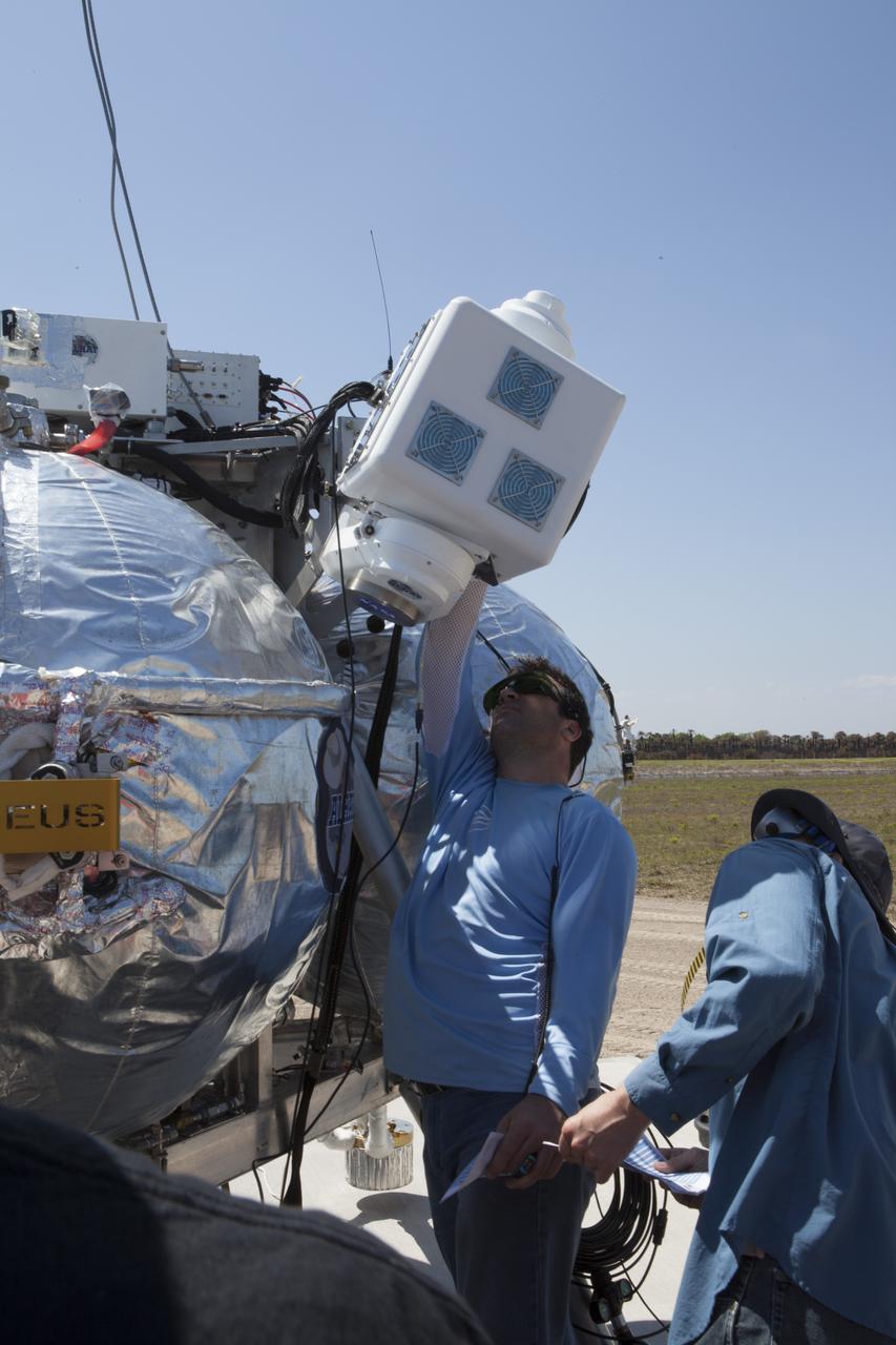
CAPE CANAVERAL, Fla. – Engineers and technicians wearing safety goggles, prepare the Project Morpheus prototype lander for an automated landing and hazard avoidance technology, or ALHAT, and laser test at a new launch site at the north end of the Shuttle Landing Facility at NASA’s Kennedy Space Center in Florida. The launch pad was moved to a different location at the landing facility to support the next phase of flight testing. The seventh free flight test of Morpheus occurred on March 11. The 83-second test began at 3:41 p.m. EDT with the Morpheus lander launching from the ground over a flame trench and ascending to 580 feet. Morpheus then flew its fastest downrange trek at 30 mph, travelling farther than before, 837 feet. The lander performed a 42-foot divert to emulate a hazard avoidance maneuver before descending and touching down on Landing Site 2, at the northern landing pad inside the ALHAT hazard field. Morpheus landed within one foot of its intended target. Project Morpheus tests NASA’s ALHAT and an engine that runs on liquid oxygen and methane, or green propellants, into a fully-operational lander that could deliver cargo to other planetary surfaces. The landing facility provides the lander with the kind of field necessary for realistic testing, complete with rocks, craters and hazards to avoid. Morpheus’ ALHAT payload allows it to navigate to clear landing sites amidst rocks, craters and other hazards during its descent. Project Morpheus is being managed under the Advanced Exploration Systems, or AES, Division in NASA’s Human Exploration and Operations Mission Directorate. The efforts in AES pioneer new approaches for rapidly developing prototype systems, demonstrating key capabilities and validating operational concepts for future human missions beyond Earth orbit. For more information on Project Morpheus, visit http://morpheuslander.jsc.nasa.gov/. Photo credit: NASA/Kim Shiflett
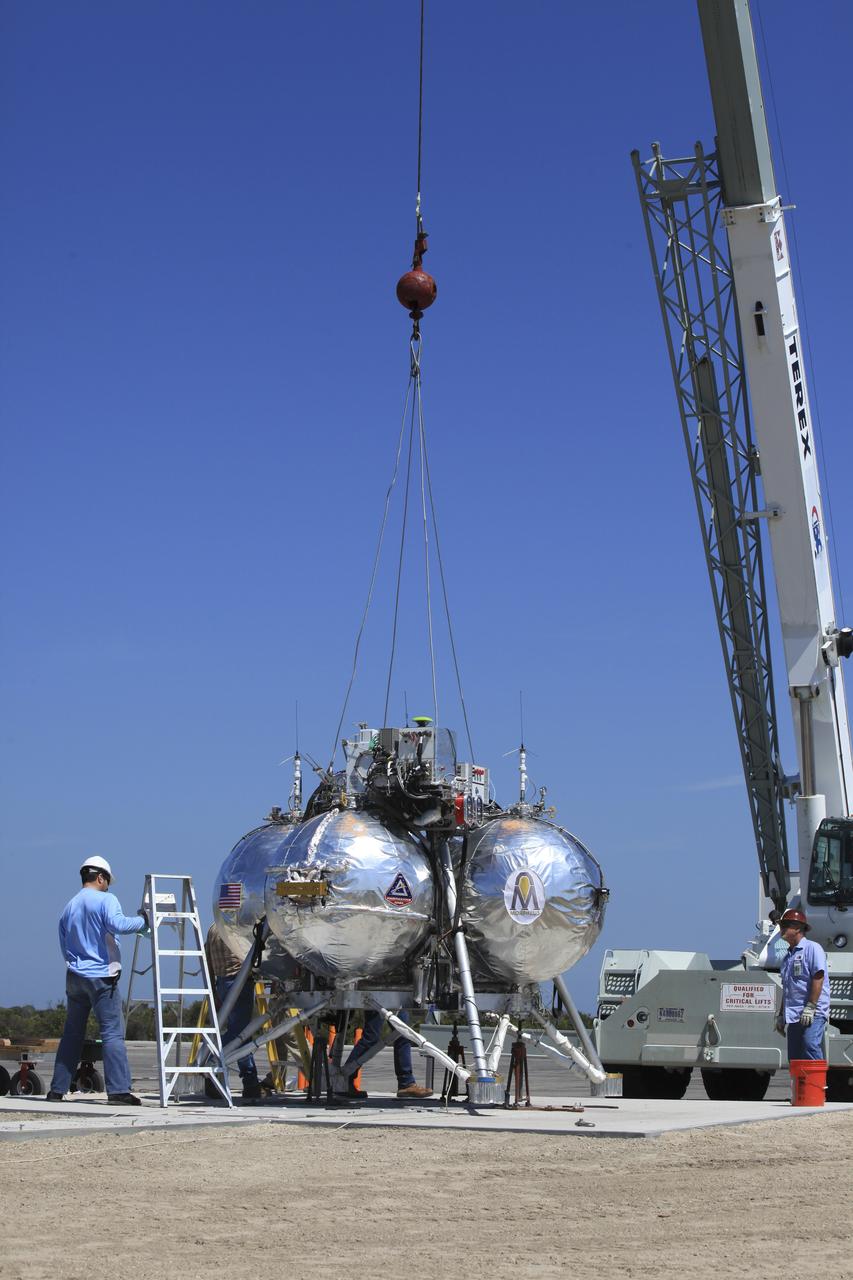
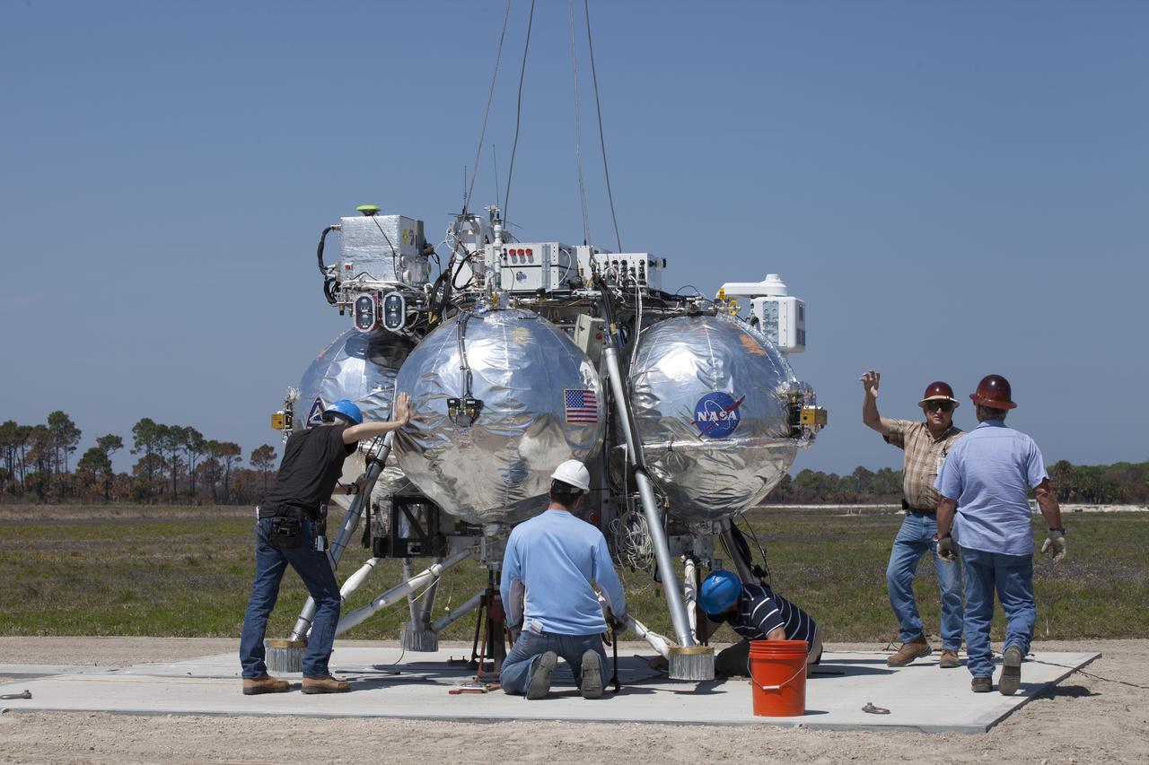
CAPE CANAVERAL, Fla. – A crane lowers the Project Morpheus prototype lander onto a launch pad at a new launch site at the north end of the Shuttle Landing Facility at NASA's Kennedy Space Center in Florida. Engineers and technicians are preparing Morpheus for an automated landing and hazard avoidance technology, or ALHAT, and laser test at the new launch site. The launch pad was moved to a different location at the landing facility to support the next phase of flight testing. The seventh free flight test of Morpheus occurred on March 11. The 83-second test began at 3:41 p.m. EDT with the Morpheus lander launching from the ground over a flame trench and ascending to 580 feet. Morpheus then flew its fastest downrange trek at 30 mph, travelling farther than before, 837 feet. The lander performed a 42-foot divert to emulate a hazard avoidance maneuver before descending and touching down on Landing Site 2, at the northern landing pad inside the ALHAT hazard field. Morpheus landed within one foot of its intended target. Project Morpheus tests NASA’s ALHAT and an engine that runs on liquid oxygen and methane, or green propellants, into a fully-operational lander that could deliver cargo to other planetary surfaces. The landing facility provides the lander with the kind of field necessary for realistic testing, complete with rocks, craters and hazards to avoid. Morpheus’ ALHAT payload allows it to navigate to clear landing sites amidst rocks, craters and other hazards during its descent. Project Morpheus is being managed under the Advanced Exploration Systems, or AES, Division in NASA’s Human Exploration and Operations Mission Directorate. The efforts in AES pioneer new approaches for rapidly developing prototype systems, demonstrating key capabilities and validating operational concepts for future human missions beyond Earth orbit. For more information on Project Morpheus, visit http://morpheuslander.jsc.nasa.gov/. Photo credit: NASA/Kim Shiflett
CAPE CANAVERAL, Fla. – Engineers and technicians prepare the Project Morpheus prototype lander for an automated landing and hazard avoidance technology, or ALHAT, and laser test at a new launch site at the north end of the Shuttle Landing Facility at NASA’s Kennedy Space Center in Florida. The launch pad was moved to a different location at the landing facility to support the next phase of flight testing. The seventh free flight test of Morpheus occurred on March 11. The 83-second test began at 3:41 p.m. EDT with the Morpheus lander launching from the ground over a flame trench and ascending to 580 feet. Morpheus then flew its fastest downrange trek at 30 mph, travelling farther than before, 837 feet. The lander performed a 42-foot divert to emulate a hazard avoidance maneuver before descending and touching down on Landing Site 2, at the northern landing pad inside the ALHAT hazard field. Morpheus landed within one foot of its intended target. Project Morpheus tests NASA’s ALHAT and an engine that runs on liquid oxygen and methane, or green propellants, into a fully-operational lander that could deliver cargo to other planetary surfaces. The landing facility provides the lander with the kind of field necessary for realistic testing, complete with rocks, craters and hazards to avoid. Morpheus’ ALHAT payload allows it to navigate to clear landing sites amidst rocks, craters and other hazards during its descent. Project Morpheus is being managed under the Advanced Exploration Systems, or AES, Division in NASA’s Human Exploration and Operations Mission Directorate. The efforts in AES pioneer new approaches for rapidly developing prototype systems, demonstrating key capabilities and validating operational concepts for future human missions beyond Earth orbit. For more information on Project Morpheus, visit http://morpheuslander.jsc.nasa.gov/. Photo credit: NASA/Kim Shiflett

AS11-40-5948 (20 July 1969) --- Astronaut Edwin E. Aldrin Jr., lunar module pilot, is photographed during the Apollo 11 extravehicular activity (EVA) on the moon. He has just deployed the Early Apollo Scientific Experiments Package (EASEP). This is a good view of the deployed equipment. In the foreground is the Passive Seismic Experiment Package (PSEP); beyond it is the Laser Ranging Retro-Reflector (LR-3); in the center background is the United States flag; in the left background is the black and white lunar surface television camera; in the far right background is the Lunar Module (LM). Astronaut Neil A. Armstrong, commander, took this picture with a 70mm lunar surface camera. While astronauts Armstrong and Aldrin descended in the Lunar Module (LM) "Eagle" to explore the Sea of Tranquility region of the moon, astronaut Michael Collins, command module pilot, remained with the Command and Service Modules (CSM) "Columbia" in lunar orbit.
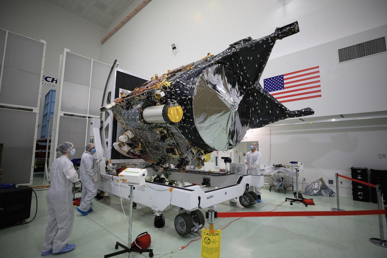
NASA's Psyche spacecraft is shown in a clean room on Dec. 8, 2022, at Astrotech Space Operations Facility near the agency's Kennedy Space Center in Florida. The spacecraft was powered on and connected to ground support equipment, enabling engineers and technicians to prepare it for launch in 2023. Teams working at Astrotech and at NASA's Jet Propulsion Laboratory in Southern California continue to monitor the health of its systems. After a one-year delay to complete critical testing, the Psyche project is targeting an October 2023 launch on a SpaceX Falcon Heavy rocket. NASA's Deep Space Optical Communications (DSOC) technology demonstration, testing high-data-rate laser communications, is integrated into Psyche and will travel with it when it launches to its target, a metal-rich asteroid, also named Psyche, that lies in the main asteroid belt. The silver-colored cylinder shown in the photo is the sunshade for DSOC, and the gold blanketing is the aperture cover for the DSOC payload. The spacecraft's target may be the partial core of a planetesimal, a building block of rocky planets in our solar system. Researchers will study Psyche using a suite of instruments including multispectral cameras, a Gamma Ray and Neutron Spectrometer (GRNS) and a magnetometer. The GRNS and magnetometer sensors are visible in the photo as the tips of the two black protrusions at the far end of the spacecraft. Also visible is the large, disc-shaped high-gain antenna, which will enable the spacecraft to communicate with Earth. https://photojournal.jpl.nasa.gov/catalog/PIA25664
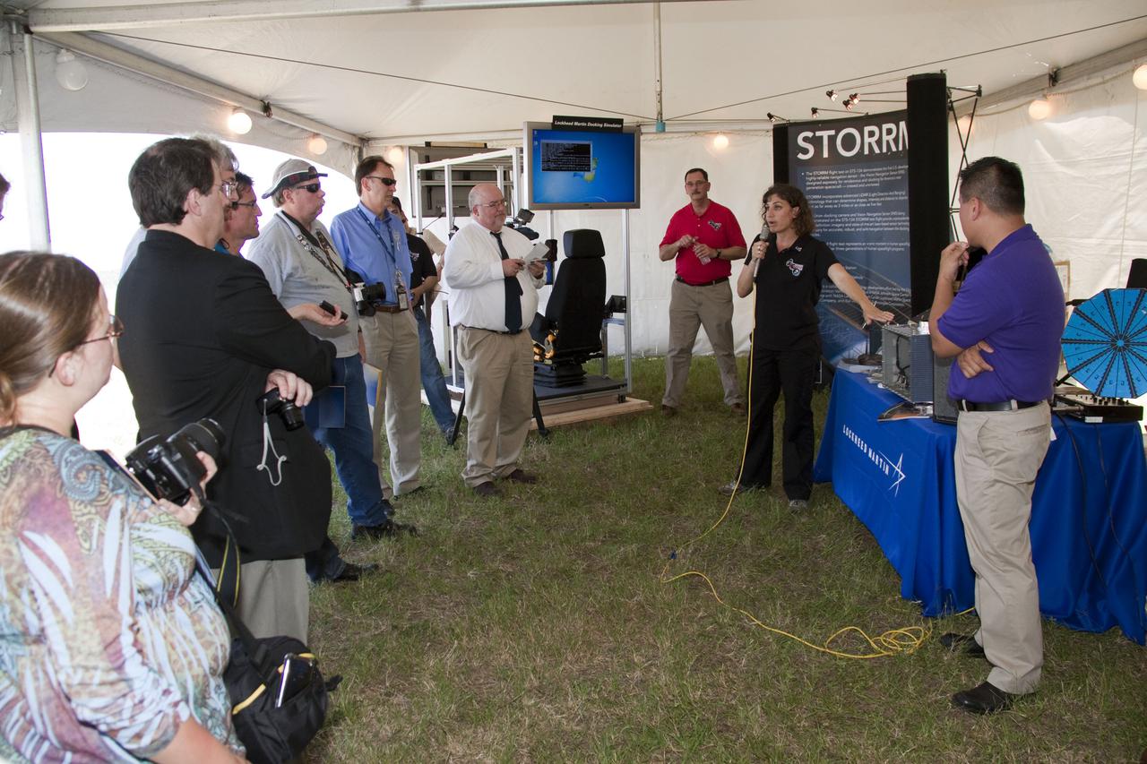
CAPE CANAVERAL, Fla. -- Heather Hinkel, principal investigator for the Sensor Test for Orion Relnav Risk Mitigation, or STORRM, Project at NASA's Johnson Space Center, provides an overview of the flight test that space shuttle Endeavour will perform on the last on-orbit day of the STS-134 mission. The overview took place at NASA's Kennedy Space Center in Florida where Endeavour is awaiting liftoff. During the mission, Endeavour will fly a dedicated maneuver to simulate an Orion rendezvous trajectory, while two Orion sensors collect visual- and laser-based relative navigation data. This will provide an unprecedented in-flight test opportunity for America's next-generation exploration spacecraft. STS-134 also will deliver the Express Logistics Carrier-3, Alpha Magnetic Spectrometer-2 (AMS), a high-pressure gas tank and additional spare parts for the Dextre robotic helper to the space station. Endeavour was scheduled to launch at 3:47 p.m. on April 29, but that attempt was scrubbed for at least 72 hours while engineers assess an issue associated with the shuttle's Auxiliary Power Unit 1. STS-134 will be the final spaceflight for Endeavour. For more information visit, www.nasa.gov_mission_pages_shuttle_shuttlemissions_sts134_index.html. Photo credit: NASA_Jack Pfaller

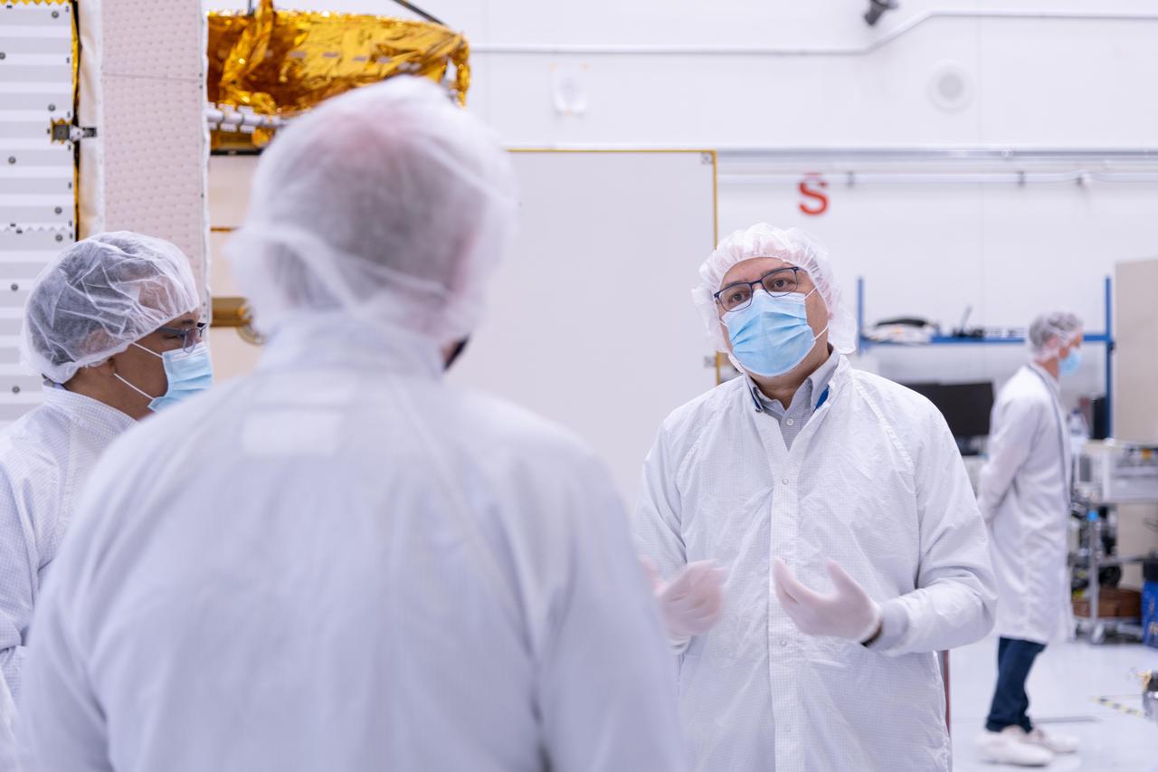
The science briefing ahead of launch for NASA’s Psyche spacecraft, a mission to a unique metal-rich asteroid. Psyche will travel nearly six years and about 2.2 billion miles (3.6 billion kilometers) – to an asteroid of the same name, which is orbiting the Sun between Mars and Jupiter. Scientists believe Psyche could be part of the core of a planetesimal, likely made of iron-nickel metal. The ore will not be mined but studied from orbit in hopes of giving researchers a better idea of what may make up Earth’s core. The Psyche spacecraft also will host a pioneering technology demonstration: NASA’s DSOC (Deep Space Optical Communications) experiment. This laser communications system will operate for the first two years of Psyche’s journey. Launch is targeted for 10:16 a.m. EDT, Thursday, Oct. 12, from Kennedy’s Launch Complex 39A. The participants include Lori Glaze, director, Planetary Sciences Division, NASA Headquarters in Washington; Lindy Elkins-Tanton, principal investigator of Psyche, Arizona State University; Ben Weiss, deputy principal investigator and magnetometer lead, Massachusetts Institute of Technology; David Oh, chief engineer for operations, NASA’s Jet Propulsion Laboratory; and Abi Biswas, project technologist for DSOC, NASA’s Jet Propulsion Laboratory.
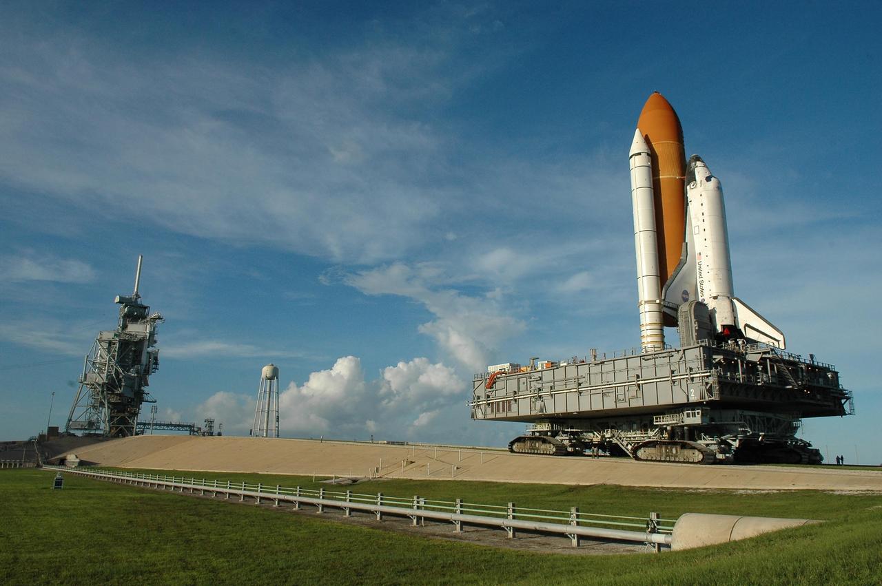
KENNEDY SPACE CENTER, FLA. - A late-day sun spotlights Space Shuttle Atlantis as it rolls up the ramp to Launch Pad 39B atop the crawler-transporter. The crawler has a leveling system designed to keep the top of the space shuttle vertical while negotiating the 5-percent grade leading to the top of the launch pad. Also, a laser docking system provides almost pinpoint accuracy when the crawler and mobile launcher platform are positioned at the launch pad. At left are the open rotating service structure and the fixed service structure topped by the 80-foot lightning mast. The shuttle had been moved off the launch pad due to concerns about the impact of Tropical Storm Ernesto, expected within 24 hours. The forecast of lesser winds expected from Ernesto and its projected direction convinced Launch Integration Manager LeRoy Cain and Shuttle Launch Director Mike Leinbach to return the shuttle to the launch pad. Photo credit: NASA/Kim Shiflett
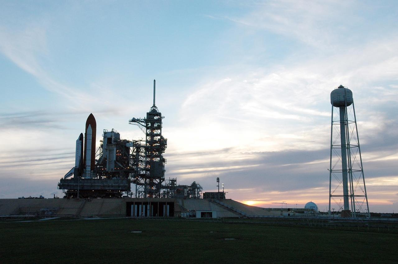
KENNEDY SPACE CENTER, FLA. - Silhouetted against a setting sun, Space Shuttle Atlantis rolls near to its launch position on Launch Pad 39B. It is being moved by a crawler-transporter. The crawler has a laser docking system that provides almost pinpoint accuracy when the crawler and mobile launcher platform are positioned at the launch pad. At right of the shuttle is the fixed service structure topped by the 80-foot lightning mast. At far right is the 300,000-tallon water tank that releases its contents prior to ignition of the shuttle's engines at liftoff. The process is part of the sound suppression water system. The shuttle had been moved off the launch pad due to concerns about the impact of Tropical Storm Ernesto, expected within 24 hours. The forecast of lesser winds expected from Ernesto and its projected direction convinced Launch Integration Manager LeRoy Cain and Shuttle Launch Director Mike Leinbach to return the shuttle to the launch pad. Photo credit: NASA/Kim Shiflett

KENNEDY SPACE CENTER, FLA. - A late-day sun spotlights Space Shuttle Atlantis as it rolls up the ramp to Launch Pad 39B atop the crawler-transporter. The crawler has a leveling system designed to keep the top of the space shuttle vertical while negotiating the 5-percent grade leading to the top of the launch pad. Also, a laser docking system provides almost pinpoint accuracy when the crawler and mobile launcher platform are positioned at the launch pad. At left are the open rotating service structure and the fixed service structure topped by the 80-foot lightning mast. The shuttle had been moved off the launch pad due to concerns about the impact of Tropical Storm Ernesto, expected within 24 hours. The forecast of lesser winds expected from Ernesto and its projected direction convinced Launch Integration Manager LeRoy Cain and Shuttle Launch Director Mike Leinbach to return the shuttle to the launch pad. Photo credit: NASA/Kim Shiflett
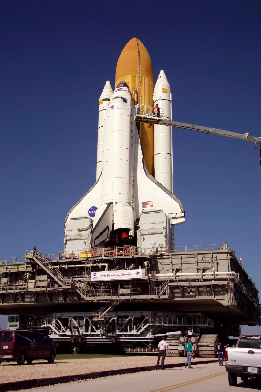
KENNEDY SPACE CENTER, FLA. - Technicians photograph the exterior of Space Shuttle Discovery on its journey to Launch Pad 39B to support the Baseline Configuration Imaging (BCI) project. BCI will be collected on each orbiter prior to every mission, beginning with STS-114. The photos will be compiled into a database available for comparison, if the need arises, to photos taken on orbit from the Shuttle's Orbital Boom Sensor System (OBSS). The 50-foot-long OBSS attaches to the Remote Manipulator System, or Shuttle robotic arm, and is one of the new safety measures for Return to Flight, equipping the orbiter with cameras and laser systems to inspect the Shuttle’s Thermal Protection System while in space. Discovery was hard down on the pad at 1:16 a.m. EDT April 7. Launch of Discovery on its Return to Flight mission, STS-114, is targeted for May 15 with a launch window that extends to June 3. During its 12-day mission, Discovery’s seven-member crew will test new hardware and techniques to improve Shuttle safety, as well as deliver supplies to the International Space Station.
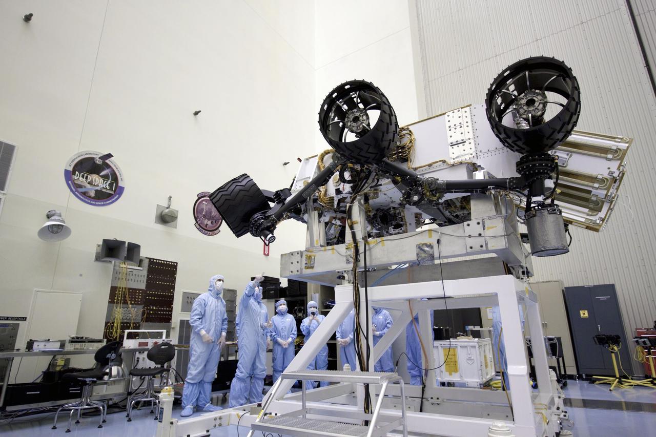
Cape Canaveral, Fla. - At the Payload Hazardous Servicing Facility at NASA's Kennedy Space Center in Florida, John Grotzinger, project scientist for NASA's Mars Science Laboratory (MSL) rover known as Curiosity, points out components of the rover to NASA Deputy Administrator Lori Garver, to his right. A United Launch Alliance Atlas V-541 configuration will be used to loft MSL into space. Curiosity’s 10 science instruments are designed to search for evidence on whether Mars has had environments favorable to microbial life, including chemical ingredients for life. The unique rover will use a laser to look inside rocks and release its gasses so that the rover’s spectrometer can analyze and send the data back to Earth. MSL is scheduled to launch from Cape Canaveral Air Force Station in Florida Nov. 25 with a window extending to Dec. 18 and arrival at Mars Aug. 2012. For more information, visit http://www.nasa.gov/msl. Photo credit: NASA/Jim Grossmann
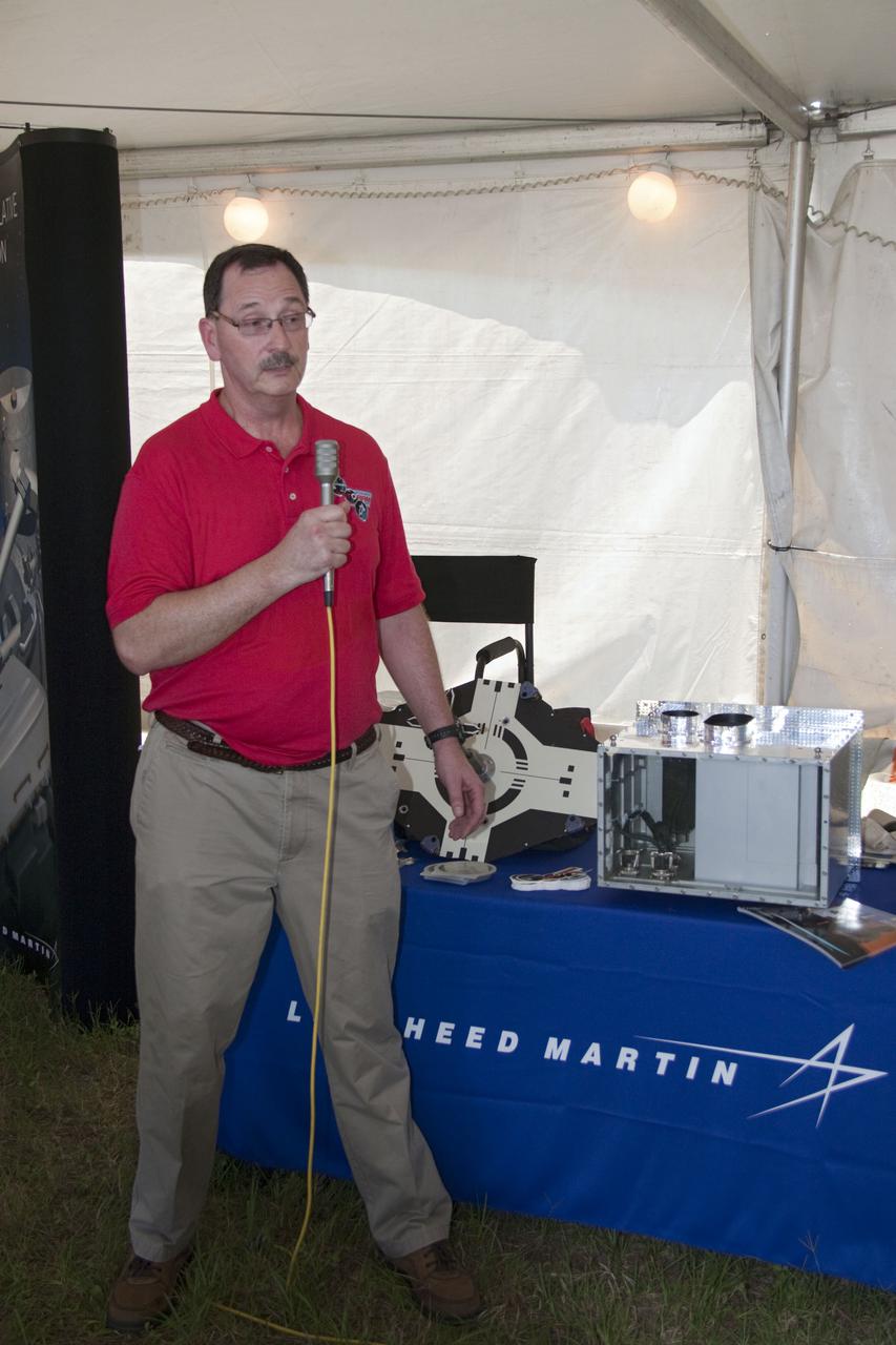
CAPE CANAVERAL, Fla. -- Frank Novak, project manager for the Sensor Test for Orion Relnav Risk Mitigation, or STORRM, at NASA's Langley Research Center in Hampton, Va., provides an overview of the flight test that space shuttle Endeavour will perform on the last on-orbit day of the STS-134 mission. The overview took place at NASA's Kennedy Space Center in Florida where Endeavour is awaiting liftoff. During the mission, Endeavour will fly a dedicated maneuver to simulate an Orion rendezvous trajectory, while two Orion sensors collect visual- and laser-based relative navigation data. This will provide an unprecedented in-flight test opportunity for America's next-generation exploration spacecraft. STS-134 also will deliver the Express Logistics Carrier-3, Alpha Magnetic Spectrometer-2 (AMS), a high-pressure gas tank and additional spare parts for the Dextre robotic helper to the space station. Endeavour was scheduled to launch at 3:47 p.m. on April 29, but that attempt was scrubbed for at least 72 hours while engineers assess an issue associated with the shuttle's Auxiliary Power Unit 1. STS-134 will be the final spaceflight for Endeavour. For more information visit, www.nasa.gov_mission_pages_shuttle_shuttlemissions_sts134_index.html. Photo credit: NASA_Jack Pfaller
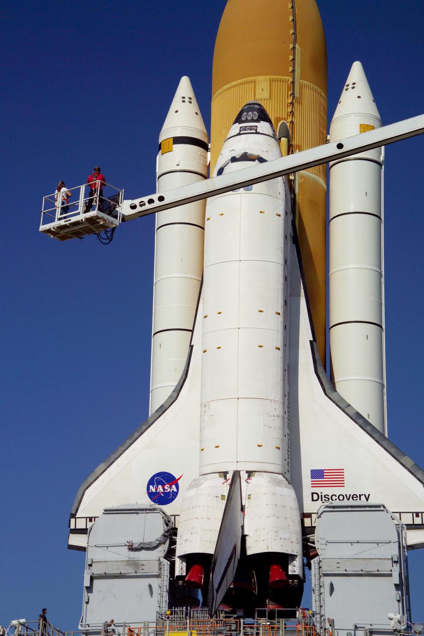
KENNEDY SPACE CENTER, FLA. - Technicians photograph the exterior of Space Shuttle Discovery on its journey to Launch Pad 39B to support the Baseline Configuration Imaging (BCI) project. BCI will be collected on each orbiter prior to every mission, beginning with STS-114. The photos will be compiled into a database available for comparison, if the need arises, to photos taken on orbit from the Shuttle's Orbital Boom Sensor System (OBSS). The 50-foot-long OBSS attaches to the Remote Manipulator System, or Shuttle robotic arm, and is one of the new safety measures for Return to Flight, equipping the orbiter with cameras and laser systems to inspect the Shuttle’s Thermal Protection System while in space. Discovery was hard down on the pad at 1:16 a.m. EDT April 7. Launch of Discovery on its Return to Flight mission, STS-114, is targeted for May 15 with a launch window that extends to June 3. During its 12-day mission, Discovery’s seven-member crew will test new hardware and techniques to improve Shuttle safety, as well as deliver supplies to the International Space Station.
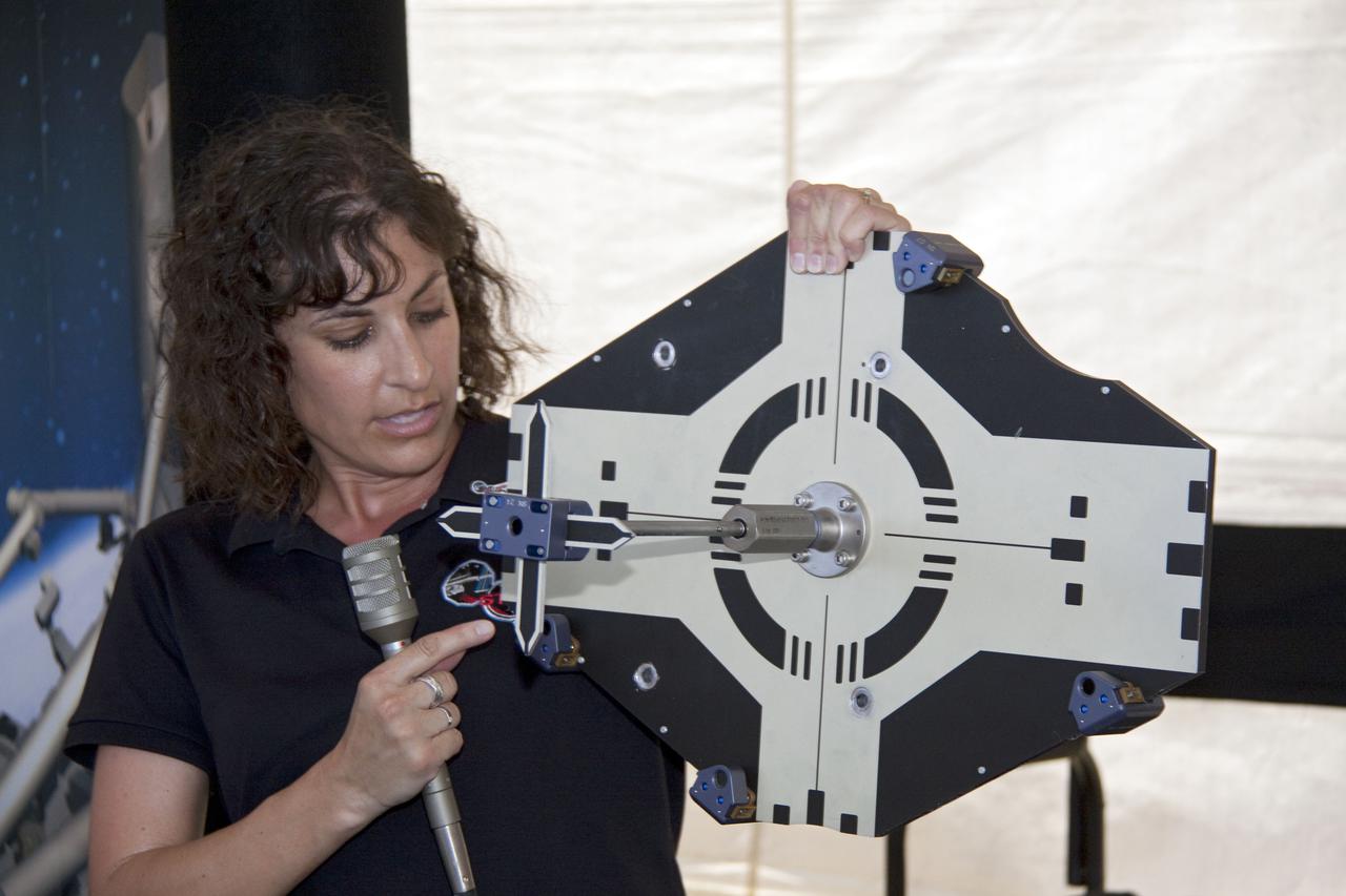
CAPE CANAVERAL, Fla. -- Heather Hinkel, principal investigator for the Sensor Test for Orion Relnav Risk Mitigation, or STORRM, Project at NASA's Johnson Space Center, provides an overview of the flight test that space shuttle Endeavour will perform on the last on-orbit day of the STS-134 mission. The overview took place at NASA's Kennedy Space Center in Florida where Endeavour is awaiting liftoff. During the mission, Endeavour will fly a dedicated maneuver to simulate an Orion rendezvous trajectory, while two Orion sensors collect visual- and laser-based relative navigation data. This will provide an unprecedented in-flight test opportunity for America's next-generation exploration spacecraft. STS-134 also will deliver the Express Logistics Carrier-3, Alpha Magnetic Spectrometer-2 (AMS), a high-pressure gas tank and additional spare parts for the Dextre robotic helper to the space station. Endeavour was scheduled to launch at 3:47 p.m. on April 29, but that attempt was scrubbed for at least 72 hours while engineers assess an issue associated with the shuttle's Auxiliary Power Unit 1. STS-134 will be the final spaceflight for Endeavour. For more information visit, www.nasa.gov_mission_pages_shuttle_shuttlemissions_sts134_index.html. Photo credit: NASA_Jack Pfaller
The new international satellite mission called Surface Water and Ocean Topography (SWOT) — slated for launch in late 2022 — will measure the height of Earth's surface water. The data the spacecraft will collect will help researchers understand and track the volume and location of water around the world. The satellite will assist with monitoring changes in floodplains and wetlands, measuring how much fresh water flows into and out of lakes and rivers and back to the ocean, and tracking regional shifts in sea level at scales never seen before. The satellite will also provide information on small-scale ocean currents that will support real-time marine operations affected by tides, currents, storm surge, sediment transport, and water quality issues. The payload is taking shape in a clean room at NASA's Jet Propulsion Laboratory in Southern California before being shipped to France. There, technicians and engineers from the French space agency Centre National d'Etudes Spatial (CNES), their prime contractor Thales Alenia Space, and JPL will complete the build and prepare the satellite for shipment to its California launch site at Vandenberg Air Force Base. JPL project manager Parag Vaze (pronounced vah-zay) is central to ensuring the handoff to his CNES counterpart Thierry Lafon goes smoothly. SWOT is being jointly developed by NASA and CNES, with contributions from the Canadian Space Agency (CSA) and United Kingdom Space Agency (UKSA). JPL, which is managed for NASA by Caltech in Pasadena, California, leads the U.S. component of the project. For the flight system, NASA is providing the Ka-band Radar Interferometer (KaRIn) instrument, a GPS science receiver, a laser retroreflector, and a two-beam microwave radiometer. CNES is providing the Doppler Orbitography and Radioposition Integrated by Satellite (DORIS) system, nadir altimeter, and the KaRIn RF subsystem (with support from the UKSA). CSA is providing the KaRIn high-power transmitter assembly. NASA is providing associated launch services. https://photojournal.jpl.nasa.gov/catalog/PIA24531
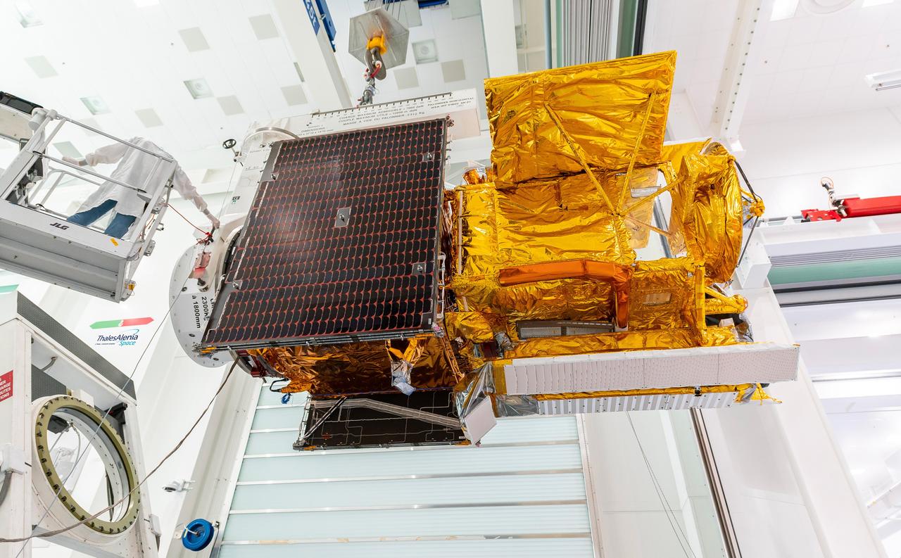
Workers in a clean room in Cannes, France, load the Surface Water and Ocean Topography (SWOT) satellite into a container in preparation for shipping the spacecraft to the U.S. SWOT is an international mission led by NASA and the French space agency Centre National d'Études Spatiales (CNES) that will survey water on more than 90% of Earth's surface. The spacecraft will view water in Earth's lakes, rivers, reservoirs, and the ocean in higher definition than ever before. The information that SWOT gathers will help inform water management decisions and prepare communities for rising seas and changing coastlines. It will also help researchers better understand the exchange of heat and carbon between the ocean and atmosphere, an important component of the role that Earth's ocean plays in the planet's climate. SWOT will launch out of the Vandenberg Space Force Base in central California no earlier than Dec. 5, 2022. SWOT is being jointly developed by NASA and CNES, with contributions from the Canadian Space Agency and the United Kingdom Space Agency. JPL, which is managed for NASA by Caltech in Pasadena, California, leads the U.S. component of the project. For the flight system payload, NASA is providing the KaRIn instrument, a GPS science receiver, a laser retroreflector, a two-beam microwave radiometer, and NASA instrument operations. CNES is providing the Doppler Orbitography and Radioposition Integrated by Satellite (DORIS) system, the dual frequency Poseidon altimeter (developed by Thales Alenia Space), the KaRIn radio-frequency subsystem (together with Thales Alenia Space and with support from the UK Space Agency), the platform, and ground control segment. CSA is providing the KaRIn high-power transmitter assembly. NASA is providing the launch vehicle and associated launch services. https://photojournal.jpl.nasa.gov/catalog/PIA24910
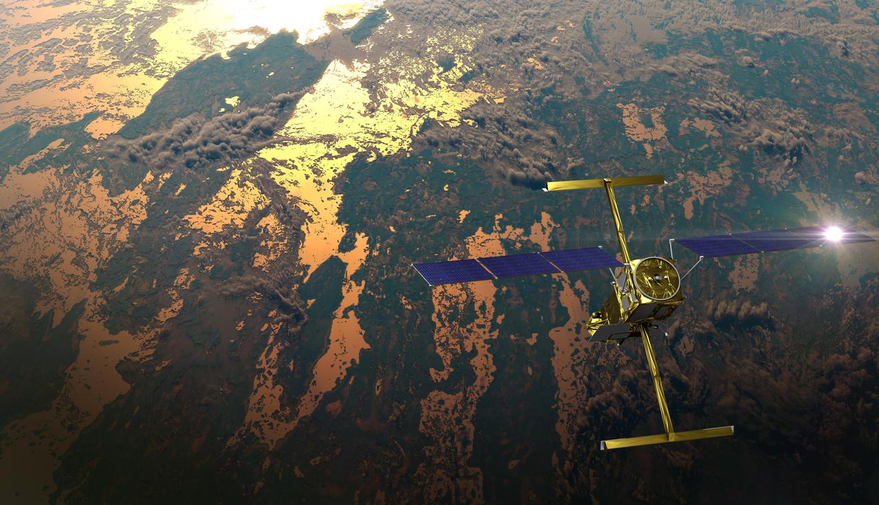
The international Surface Water and Ocean Topography (SWOT) satellite is shown in orbit over Earth in this illustration, with sunlight glinting off one of its solar arrays and both antennas of its Ka-band Radar Interferometer (KaRIn) instrument extended. The mission is a collaborative effort between NASA and the French space agency Centre National d'Études Spatiales (CNES) – with contributions from the Canadian Space Agency (CSA) and the UK Space Agency. KaRIn is the scientific heart of the SWOT satellite, which will survey the water on more than 90% of Earth's surface, measuring the height of water in lakes, rivers, reservoirs, and the ocean. To do that, KaRIn will transmit radar pulses to Earth's surface and use its two antennas to triangulate the return signals that bounce back. Mounted at the ends of a boom 33 feet (10 meters) long, the antennas will collect data along a swath 30 miles (50 kilometers) wide on either side of the satellite. KaRIn will operate in two modes: A lower-resolution mode over the ocean will involve significant onboard processing of the data to reduce the volume of information sent during downlinks to Earth; a higher-resolution mode will be used mainly over land. Scheduled to launch from Vandenberg Space Force Base in Central California on Dec. 15, 2022, SWOT is being jointly developed by NASA and CNES, with contributions from the CSA and the UK Space Agency. NASA's Jet Propulsion Laboratory, which is managed for the agency by Caltech in Pasadena, California, leads the U.S. component of the project. For the flight system payload, NASA is providing the Ka-band Radar Interferometer (KaRIn) instrument, a GPS science receiver, a laser retroreflector, a two-beam microwave radiometer, and NASA instrument operations. CNES is providing the Doppler Orbitography and Radioposition Integrated by Satellite (DORIS) system, the dual frequency Poseidon altimeter (developed by Thales Alenia Space), the KaRIn radio-frequency subsystem (together with Thales Alenia Space and with support from the UK Space Agency), the satellite platform, and ground control segment. CSA is providing the KaRIn high-power transmitter assembly. NASA is providing the launch vehicle and associated launch services. https://photojournal.jpl.nasa.gov/catalog/PIA25595
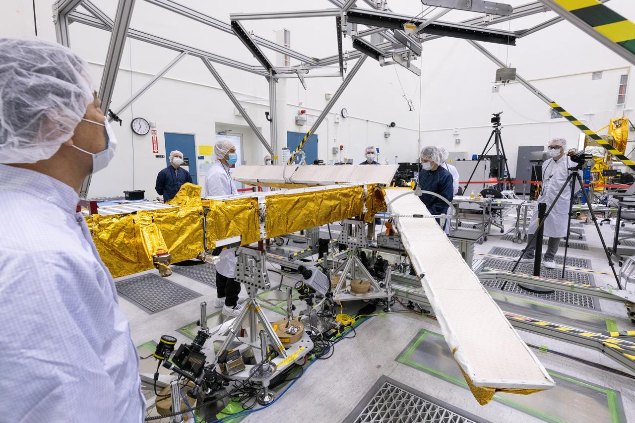
Members of the international Surface Water and Ocean Topography (SWOT) mission test one of the antennas for the Ka-band Radar Interferometer (KaRIn) instrument in a clean room at NASA's Jet Propulsion Laboratory in Southern California. The mission is a collaborative effort between NASA and the French space agency Centre National d'Études Spatiales (CNES) – with contributions from the Canadian Space Agency (CSA) and the UK Space Agency. KaRIn is the scientific heart of the SWOT satellite, which will survey the water on more than 90% of Earth's surface, measuring the height of water in lakes, rivers, reservoirs, and the ocean. To do that, KaRIn will transmit radar pulses to Earth's surface and use its two antennas to triangulate the return signals that bounce back. Mounted at the ends of a boom 33 feet (10 meters) long, the antennas will collect data along a swath 30 miles (50 kilometers) wide on either side of the satellite. KaRIn will operate in two modes: A lower-resolution mode over the ocean will involve significant onboard processing of the data to reduce the volume of information sent during downlinks to Earth; a higher-resolution mode will be used mainly over land. Scheduled to launch from Vandenberg Space Force Base in Central California on Dec. 15, 2022, SWOT is being jointly developed by NASA and CNES, with contributions from the CSA and the UK Space Agency. NASA's Jet Propulsion Laboratory, which is managed for the agency by Caltech in Pasadena, California, leads the U.S. component of the project. For the flight system payload, NASA is providing the Ka-band Radar Interferometer (KaRIn) instrument, a GPS science receiver, a laser retroreflector, a two-beam microwave radiometer, and NASA instrument operations. CNES is providing the Doppler Orbitography and Radioposition Integrated by Satellite (DORIS) system, the dual frequency Poseidon altimeter (developed by Thales Alenia Space), the KaRIn radio-frequency subsystem (together with Thales Alenia Space and with support from the UK Space Agency), the satellite platform, and ground control segment. CSA is providing the KaRIn high-power transmitter assembly. NASA is providing the launch vehicle and associated launch services. https://photojournal.jpl.nasa.gov/catalog/PIA25594

NASA's Wallops Flight Facility is located on Wallops Island, Va. and is the site of tonight's moon mission launch. Satellite imagery from NOAA's GOES-East satellite shows that high pressure remains in control over the Mid-Atlantic region, providing an almost cloud-free sky. This visible image of the Mid-Atlantic was captured by NOAA's GOES-East satellite at 17:31 UTC/1:31 p.m. EDT and shows some fair weather clouds over the Delmarva Peninsula (which consists of the state of Delaware and parts of Maryland and Virginia - which together is "Delmarva") and eastern Virginia and North Carolina. Most of the region is cloud-free, making for a perfect viewing night to see a launch. NOAA operates GOES-East and NASA's GOES Project at the NASA Goddard Space Flight Center in Greenbelt, Md. creates images and animations from the data. NOAA's National Weather Service forecast for tonight, Sept. 6 calls for winds blowing from the east to 11 mph, with clear skies and overnight temperatures dropping to the mid-fifties. The Lunar Atmosphere and Dust Environment Explorer, known as LADEE (pronounced like "laddie"), launches tonight at 11:27 p.m. EDT from Pad 0B at the Mid-Atlantic Regional Spaceport, at NASA Wallops and will be visible along the Mid-Atlantic with tonight's perfect weather conditions. LADEE is managed by NASA's Ames Research Center in Moffett Field, Calif. This will be the first launch to lunar orbit from NASA Wallops and the first launch of a Minotaur V rocket – the biggest ever launched from Wallops. NASA's LADEE is a robotic mission that will orbit the moon to gather detailed information about the lunar atmosphere, conditions near the surface and environmental influences on lunar dust. A thorough understanding of these characteristics will address long-standing unknowns, and help scientists understand other planetary bodies as well. LADEE also carries an important secondary payload, the Lunar Laser Communication Demonstration, or LLCD, which will help us open a new era of space communications by becoming NASA's first high rate, two-way, space laser system. Live coverage of the launch can be seen beginning at 9:30 p.m. EDT on NASA-TV at: <a href="http://www.nasa.gov/ntv" rel="nofollow">www.nasa.gov/ntv</a> For more information about LADEE, visit: <a href="http://www.nasa.gov/ladee" rel="nofollow">www.nasa.gov/ladee</a> <b><a href="http://www.nasa.gov/audience/formedia/features/MP_Photo_Guidelines.html" rel="nofollow">NASA image use policy.</a></b> <b><a href="http://www.nasa.gov/centers/goddard/home/index.html" rel="nofollow">NASA Goddard Space Flight Center</a></b> enables NASA’s mission through four scientific endeavors: Earth Science, Heliophysics, Solar System Exploration, and Astrophysics. Goddard plays a leading role in NASA’s accomplishments by contributing compelling scientific knowledge to advance the Agency’s mission. <b>Follow us on <a href="http://twitter.com/NASA_GoddardPix" rel="nofollow">Twitter</a></b> <b>Like us on <a href="http://www.facebook.com/pages/Greenbelt-MD/NASA-Goddard/395013845897?ref=tsd" rel="nofollow">Facebook</a></b> <b>Find us on <a href="http://instagram.com/nasagoddard?vm=grid" rel="nofollow">Instagram</a></b>

Wonders in the Antarctic Sea and Sky NASA aircraft and scientists have returned to the United States after a short ice-surveying mission to #Antarctica. Despite having only a week of flying time, the team returned with crucial scientific data and a trove of spectacular aerial photographs. The flights over Antarctica were part of Operation #IceBridge, a multi-year mission to monitor conditions in Antarctica and the Arctic until a new ice-monitoring satellite, ICESat-2, launches in 2016. ICESat-1 was decommissioned in 2009, and IceBridge aircraft have been flying ever since. Laser altimeter and radar data are the primary products of the mission, but IceBridge project scientist Michael Studinger almost always has his digital camera ready as well. On November 24, 2013, he took this photograph of a multi-layered lenticular cloud hovering near Mount Discovery, a volcano about 70 kilometers (44 miles) southwest of McMurdo. Lenticular #clouds are a type of wave cloud. They usually form when a layer of air near the surface encounters a topographic barrier, gets pushed upward, and flows over it as a series of atmospheric gravity waves. Lenticular clouds form at the crest of the waves, where the air is coolest and water vapor is most likely to condense into cloud droplets. The bulging sea ice in the foreground is a pressure ridge, which formed when separate ice floes collided and piled up on each other. Read more: <a href="http://1.usa.gov/18lXIQS" rel="nofollow">1.usa.gov/18lXIQS</a> Photograph courtesy of Michael Studinger. Caption by Adam Voiland of NASA's Earth Observatory. <b><a href="http://www.nasa.gov/audience/formedia/features/MP_Photo_Guidelines.html" rel="nofollow">NASA image use policy.</a></b> <b><a href="http://www.nasa.gov/centers/goddard/home/index.html" rel="nofollow">NASA Goddard Space Flight Center</a></b> enables NASA’s mission through four scientific endeavors: Earth Science, Heliophysics, Solar System Exploration, and Astrophysics. Goddard plays a leading role in NASA’s accomplishments by contributing compelling scientific knowledge to advance the Agency’s mission. <b>Follow us on <a href="http://twitter.com/NASA_GoddardPix" rel="nofollow">Twitter</a></b> <b>Like us on <a href="http://www.facebook.com/pages/Greenbelt-MD/NASA-Goddard/395013845897?ref=tsd" rel="nofollow">Facebook</a></b> <b>Find us on <a href="http://instagram.com/nasagoddard?vm=grid" rel="nofollow">Instagram</a></b>

The X-37 advanced technology demonstrator flaperon unit was one of the first ever thermal and mechanical qualification tests of a carbon-carbon control surface designed for space flight. The test also featured extensive use of high-temperature fiber optic strain sensors. Peak temperatures reached 2,500 degrees Fahrenheit.
Anthony piazza, a researcher at NASA’s Armstrong Flight Research center in Edwards, California, works with high-temperature strain sensors. This test article is a bending load bar, which enables high-temperature optical strain sensor research up to 1,800 degrees Fahrenheit.
Anthony piazza, a researcher at NASA’s Armstrong Flight Research center in Edwards, California, works with high-temperature strain sensors. This test article is a bending load bar, which enables high-temperature optical strain sensor research up to 1,800 degrees Fahrenheit.
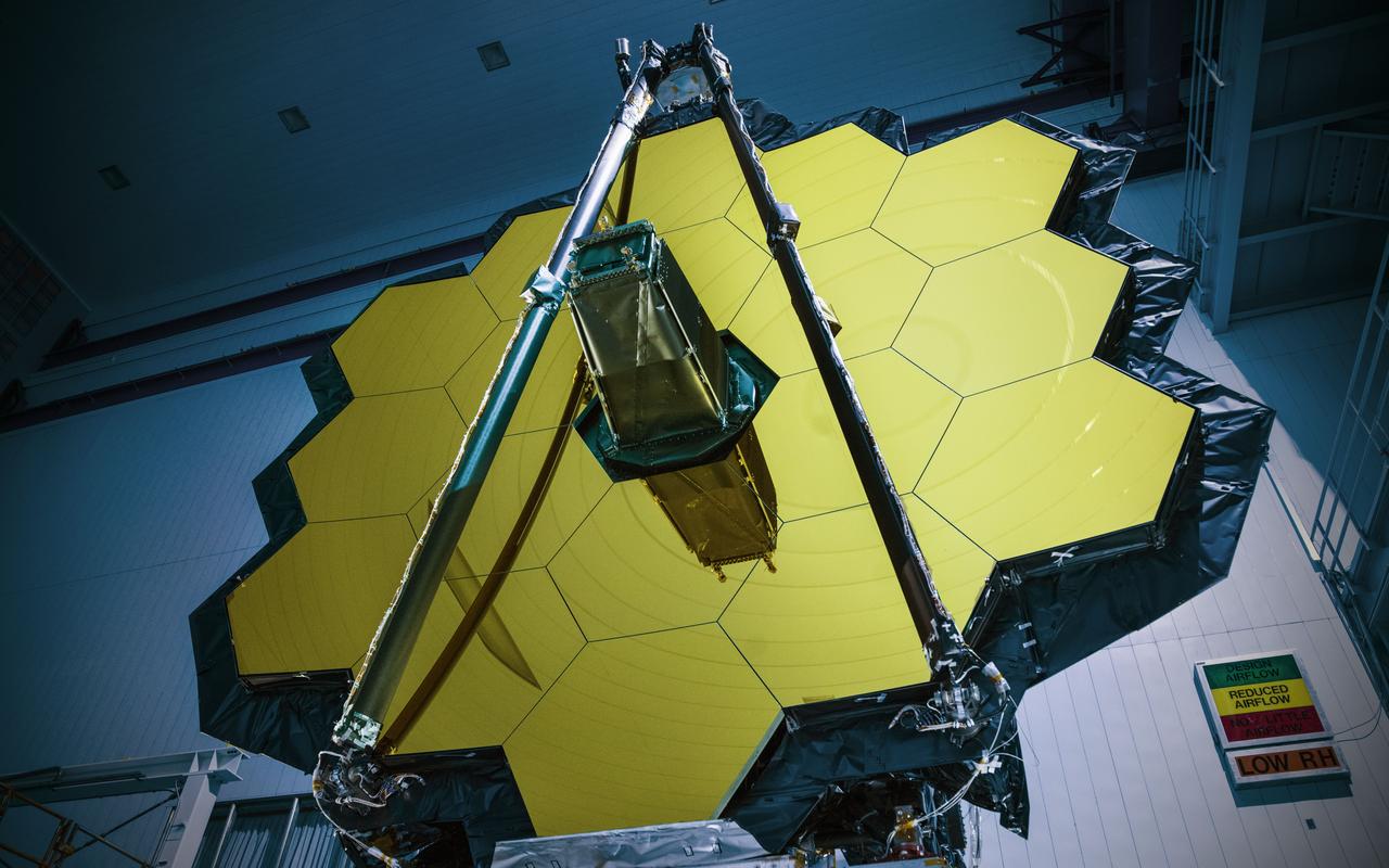
NASA’s James Webb Space Telescope has successfully passed the center of curvature test, an important optical measurement of Webb’s fully assembled primary mirror prior to cryogenic testing, and the last test held at NASA's Goddard Space Flight Center in Greenbelt, Maryland, before the spacecraft is shipped to NASA’s Johnson Space Center in Houston for more testing. After undergoing rigorous environmental tests simulating the stresses of its rocket launch, the Webb telescope team at Goddard analyzed the results from this critical optical test and compared it to the pre-test measurements. The team concluded that the mirrors passed the test with the optical system unscathed. “The Webb telescope is about to embark on its next step in reaching the stars as it has successfully completed its integration and testing at Goddard. It has taken a tremendous team of talented individuals to get to this point from all across NASA, our industry and international partners, and academia,” said Bill Ochs, NASA’s Webb telescope project manager. “It is also a sad time as we say goodbye to the Webb Telescope at Goddard, but are excited to begin cryogenic testing at Johnson.” Rocket launches create high levels of vibration and noise that rattle spacecraft and telescopes. At Goddard, engineers tested the Webb telescope in vibration and acoustics test facilities that simulate the launch environment to ensure that functionality is not impaired by the rigorous ride on a rocket into space. Before and after these environmental tests took place, optical engineers set up an interferometer, the main device used to measure the shape of the Webb telescope’s mirror. An interferometer gets its name from the process of recording and measuring the ripple patterns that result when different beams of light mix and their waves combine or “interfere.” Waves of visible light are less than a thousandth of a millimeter long and optics on the Webb telescope need to be shaped and aligned even more accurately than that to work correctly. Making measurements of the mirror shape and position by lasers prevents physical contact and damage (scratches to the mirror). So, scientists use wavelengths of light to make tiny measurements. By measuring light reflected off the optics using an interferometer, they are able to measure extremely small changes in shape or position that may occur after exposing the mirror to a simulated launch or temperatures that simulate the subfreezing environment of space. During a test conducted by a team from Goddard, Ball Aerospace of Boulder, Colorado, and the Space Telescope Science Institute in Baltimore, temperature and humidity conditions in the clean room were kept incredibly stable to minimize fluctuations in the sensitive optical measurements over time. Even so, tiny vibrations are ever-present in the clean room that cause jitter during measurements, so the interferometer is a “high-speed” one, taking 5,000 “frames” every second, which is a faster rate than the background vibrations themselves. This allows engineers to subtract out jitter and get good, clean results on any changes to the mirror's shape. Credit: NASA/Goddard/Chris Gunn Read more: <a href="https://go.nasa.gov/2oPqHwR" rel="nofollow">go.nasa.gov/2oPqHwR</a> NASA’s Webb Telescope Completes Goddard Testing