
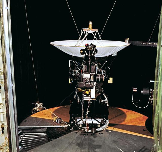
This archival photo shows the Voyager Proof Test Model (in the foreground right of center) undergoing a mechanical preparation and weight center of gravity test at NASA's Jet Propulsion Laboratory, Pasadena, California, on January 12, 1977. https://photojournal.jpl.nasa.gov/catalog/PIA21476

This archival photo shows the Voyager Proof Test Model undergoing a mechanical preparation and weight center of gravity test at NASA's Jet Propulsion Laboratory, Pasadena, California, on January 12, 1977. The stack of three white cylinders seen near center is a stand-in for the spacecraft's power generators (called RTGs). Above that, a silvery canister holds the spacecraft's magnetometer in its stowed configuration. https://photojournal.jpl.nasa.gov/catalog/PIA21477
This archival photo shows the Voyager proof test model, which did not fly in space, in the 25-foot space simulator chamber at NASA's Jet Propulsion Laboratory, Pasadena, California. https://photojournal.jpl.nasa.gov/catalog/PIA21726

This archival photo shows the Voyager proof test model, which did not fly in space, in the 25-foot space simulator chamber at NASA's Jet Propulsion Laboratory on December 3, 1976. https://photojournal.jpl.nasa.gov/catalog/PIA21735
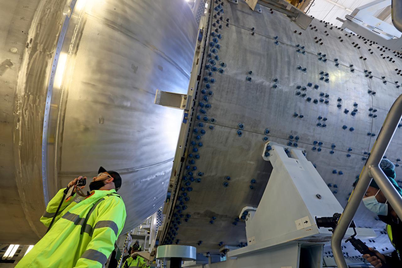
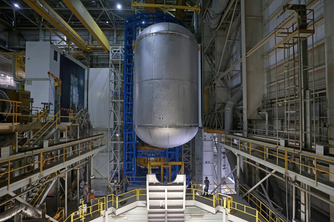
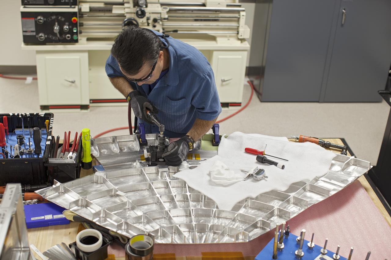
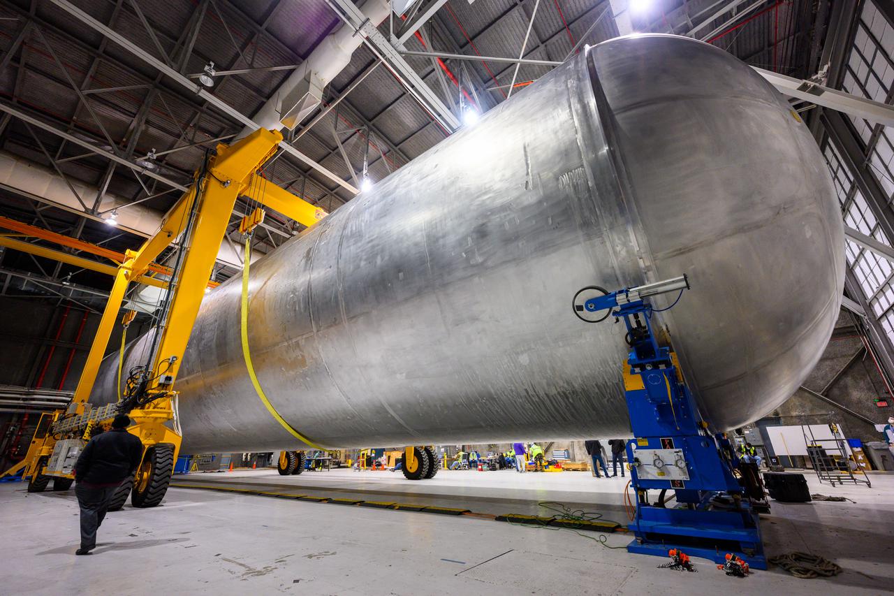
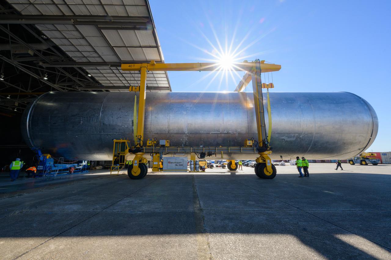
The core stage liquid hydrogen tank for the Artemis III mission completed proof testing, and technicians returned it to the main factory building at NASA’s Michoud Assembly Facility in New Orleans where it will undergo more outfitting. As part of proof testing, technicians apply a simple soap solution and check for leaks by observing any bubble formation on the welds. The technician removed the bubble solution with distilled water and then dried the area of application to prevent corrosion. To build the Space Launch System (SLS) rocket’s 130-foot core stage liquid hydrogen tank, engineers use robotic tools to weld five-barrel segments. This process results in a tank with around 1,900 feet, or more than six football fields, of welds that must be tested by hand. After the leak tests, the core stage lead, Boeing, pressurized the SLS tank to further ensure there were no leaks. After it passed proof testing, technicians moved the Artemis III liquid hydrogen tank to Michoud’s main factory. Soon, the technicians will prime and apply a foam-based thermal protection system that protects the tank during launch. Later, the tank will be joined with other parts of the core stage to form the entire 212-foot rocket stage with its four RS-25 engines that produce 2 million pounds of thrust to help launch the rocket. Artemis III will land the first astronauts on the lunar surface.
The core stage liquid hydrogen tank for the Artemis III mission completed proof testing, and technicians returned it to the main factory building at NASA’s Michoud Assembly Facility in New Orleans where it will undergo more outfitting. As part of proof testing, technicians apply a simple soap solution and check for leaks by observing any bubble formation on the welds. The technician removed the bubble solution with distilled water and then dried the area of application to prevent corrosion. To build the Space Launch System (SLS) rocket’s 130-foot core stage liquid hydrogen tank, engineers use robotic tools to weld five-barrel segments. This process results in a tank with around 1,900 feet, or more than six football fields, of welds that must be tested by hand. After the leak tests, the core stage lead, Boeing, pressurized the SLS tank to further ensure there were no leaks. After it passed proof testing, technicians moved the Artemis III liquid hydrogen tank to Michoud’s main factory. Soon, the technicians will prime and apply a foam-based thermal protection system that protects the tank during launch. Later, the tank will be joined with other parts of the core stage to form the entire 212-foot rocket stage with its four RS-25 engines that produce 2 million pounds of thrust to help launch the rocket. Artemis III will land the first astronauts on the lunar surface.
The core stage liquid hydrogen tank for the Artemis III mission completed proof testing, and technicians returned it to the main factory building at NASA’s Michoud Assembly Facility in New Orleans where it will undergo more outfitting. As part of proof testing, technicians apply a simple soap solution and check for leaks by observing any bubble formation on the welds. The technician removed the bubble solution with distilled water and then dried the area of application to prevent corrosion. To build the Space Launch System (SLS) rocket’s 130-foot core stage liquid hydrogen tank, engineers use robotic tools to weld five-barrel segments. This process results in a tank with around 1,900 feet, or more than six football fields, of welds that must be tested by hand. After the leak tests, the core stage lead, Boeing, pressurized the SLS tank to further ensure there were no leaks. After it passed proof testing, technicians moved the Artemis III liquid hydrogen tank to Michoud’s main factory. Soon, the technicians will prime and apply a foam-based thermal protection system that protects the tank during launch. Later, the tank will be joined with other parts of the core stage to form the entire 212-foot rocket stage with its four RS-25 engines that produce 2 million pounds of thrust to help launch the rocket. Artemis III will land the first astronauts on the lunar surface.
The core stage liquid hydrogen tank for the Artemis III mission completed proof testing, and technicians returned it to the main factory building at NASA’s Michoud Assembly Facility in New Orleans where it will undergo more outfitting. As part of proof testing, technicians apply a simple soap solution and check for leaks by observing any bubble formation on the welds. The technician removed the bubble solution with distilled water and then dried the area of application to prevent corrosion. To build the Space Launch System (SLS) rocket’s 130-foot core stage liquid hydrogen tank, engineers use robotic tools to weld five-barrel segments. This process results in a tank with around 1,900 feet, or more than six football fields, of welds that must be tested by hand. After the leak tests, the core stage lead, Boeing, pressurized the SLS tank to further ensure there were no leaks. After it passed proof testing, technicians moved the Artemis III liquid hydrogen tank to Michoud’s main factory. Soon, the technicians will prime and apply a foam-based thermal protection system that protects the tank during launch. Later, the tank will be joined with other parts of the core stage to form the entire 212-foot rocket stage with its four RS-25 engines that produce 2 million pounds of thrust to help launch the rocket. Artemis III will land the first astronauts on the lunar surface.
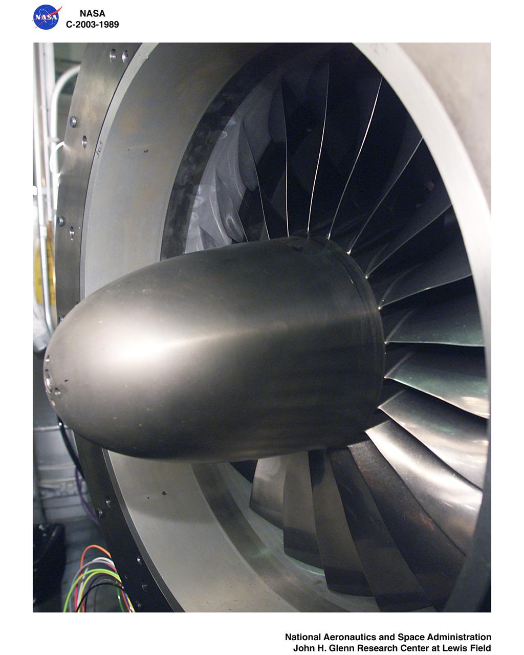
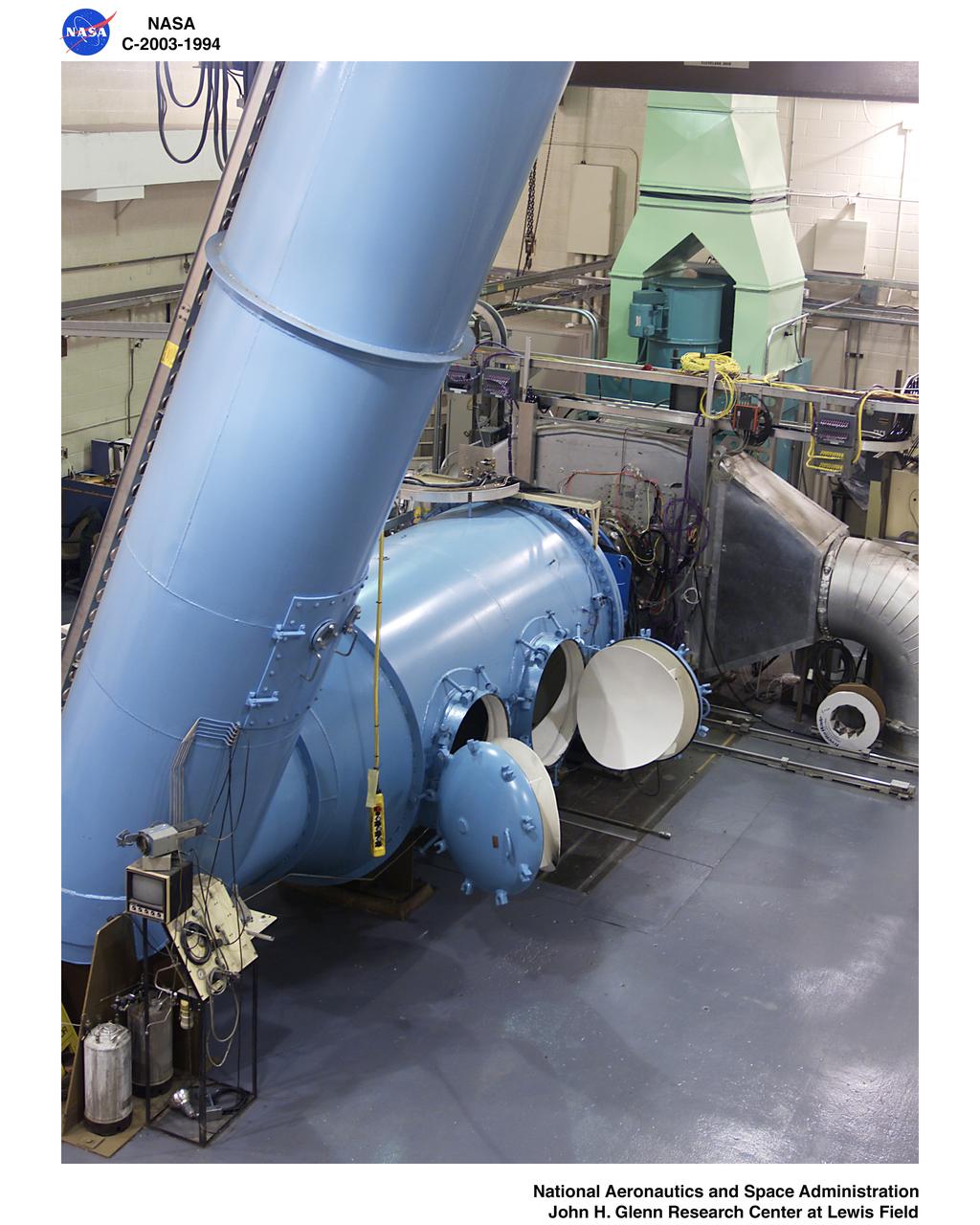
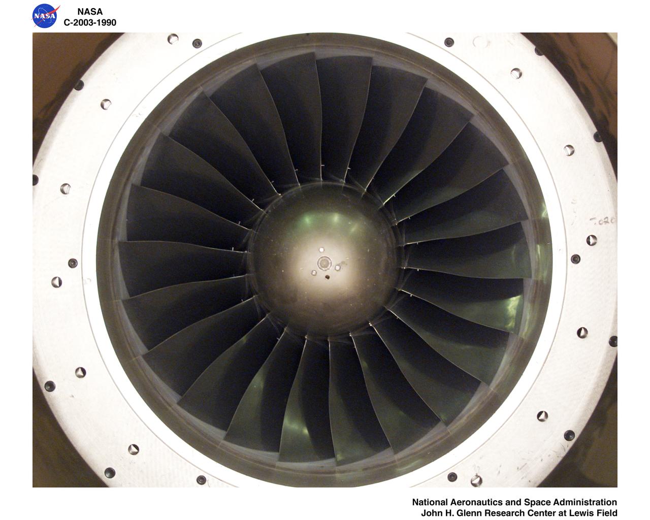
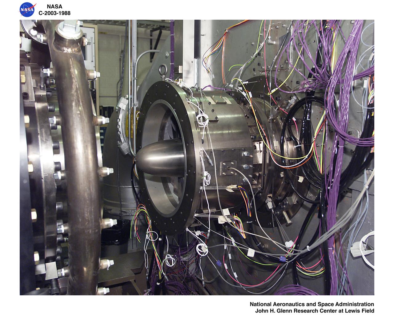
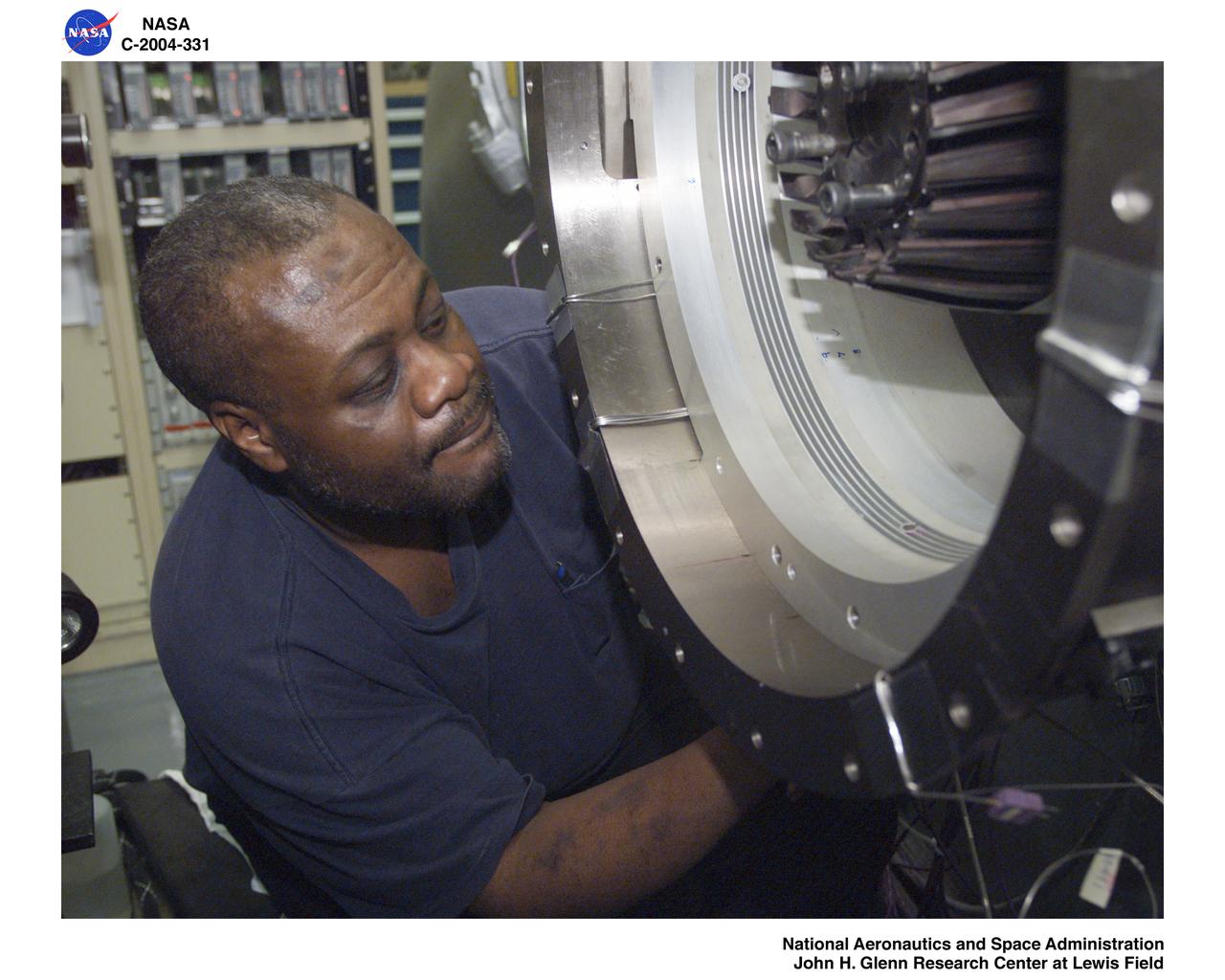
Ultra-Efficient Engine Technology - UEET - Proof of Concept Compressor - POCC - Advanced Compressor Casing Treatment Testing
Ultra-Efficient Engine Technology - UEET - Proof of Concept Compressor - POCC - Advanced Compressor Casing Treatment Testing
Ultra-Efficient Engine Technology - UEET - Proof of Concept Compressor - POCC - Advanced Compressor Casing Treatment Testing
Ultra-Efficient Engine Technology - UEET - Proof of Concept Compressor - POCC - Advanced Compressor Casing Treatment Testing
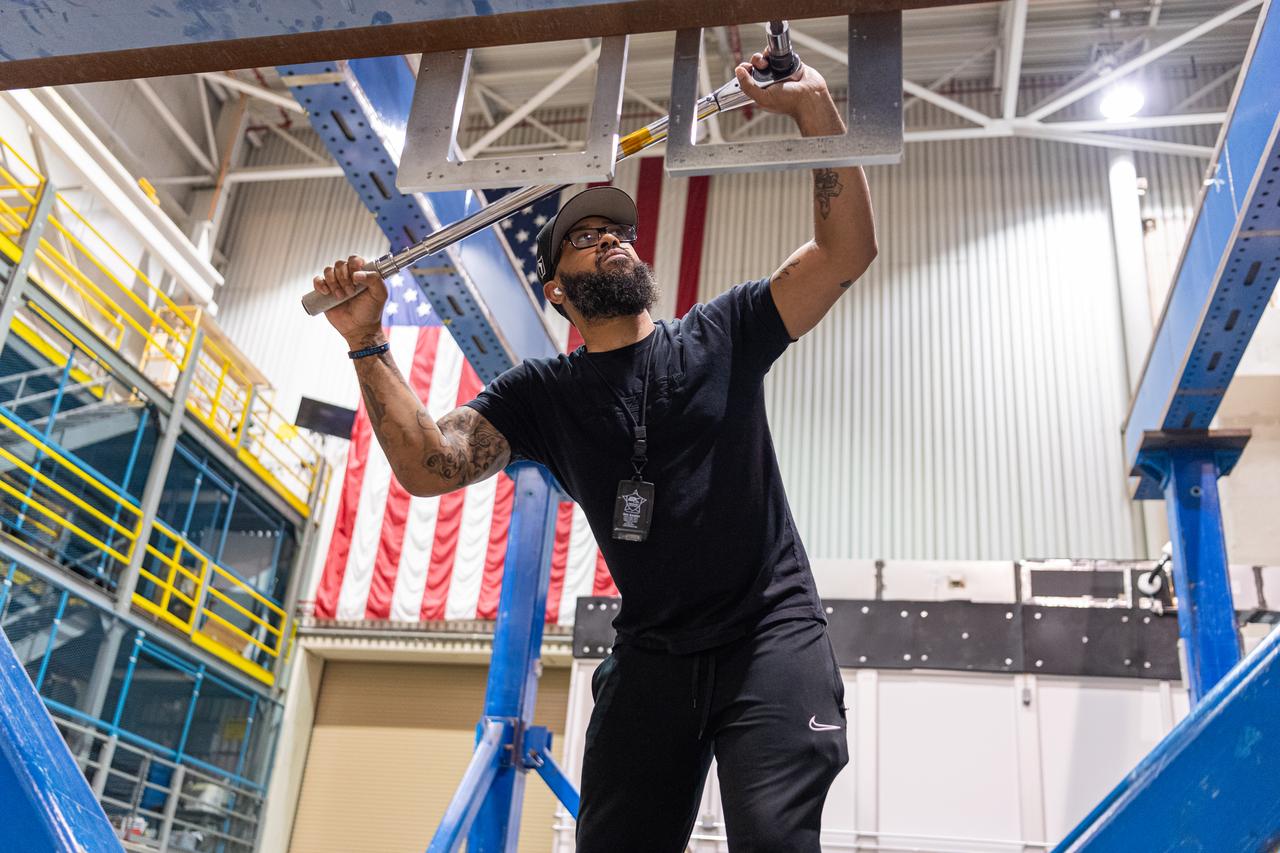
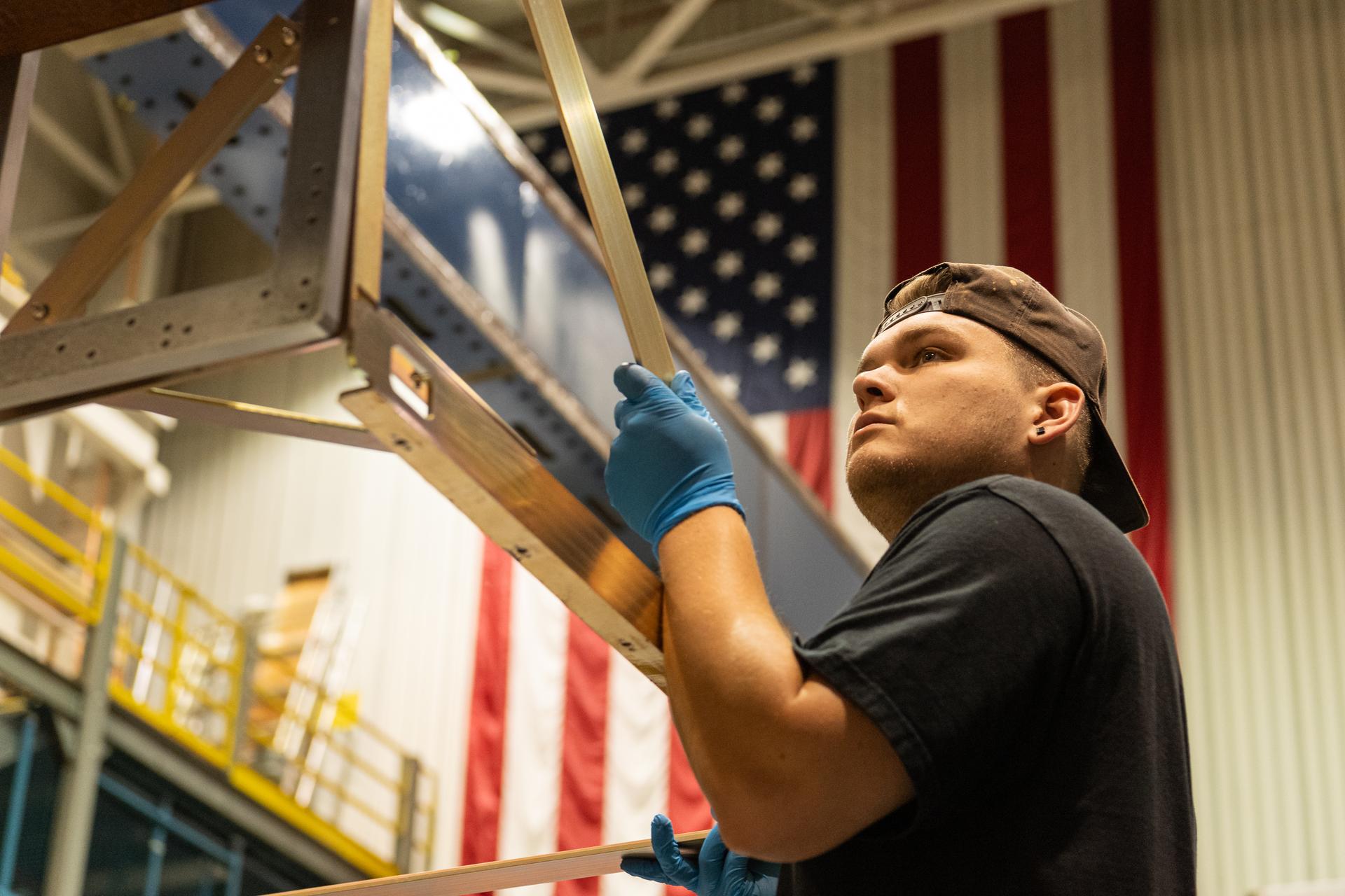
Mechanical engineering and integration technician Ivan Pratt installs brackets onto the static load testing platform in preparation of an OSAM-1 ground support equipment proof test at Goddard Space Flight Center, Greenbelt Md., July 19, 2023. This photo has been reviewed by OSAM1 project management and the Export Control Office and is released for public view. NASA/Mike Guinto
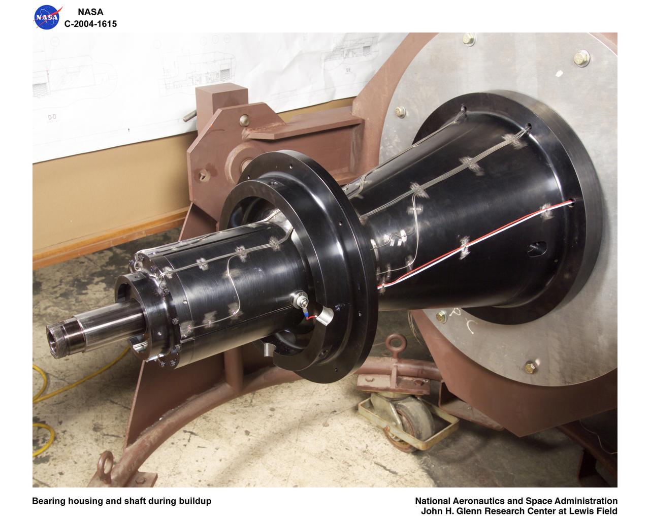
Ultra-Efficient Engine Technology (UEET), Proof of Concept Compressor, Advanced Compressor Casing Treatment testing; bearing housing and shaft during build-up
Ultra-Efficient Engine Technology (UEET) Proof of Concept Compressor, Advanced Compressor Casing Treatment testing, First Research Configuration (concentric grooves)
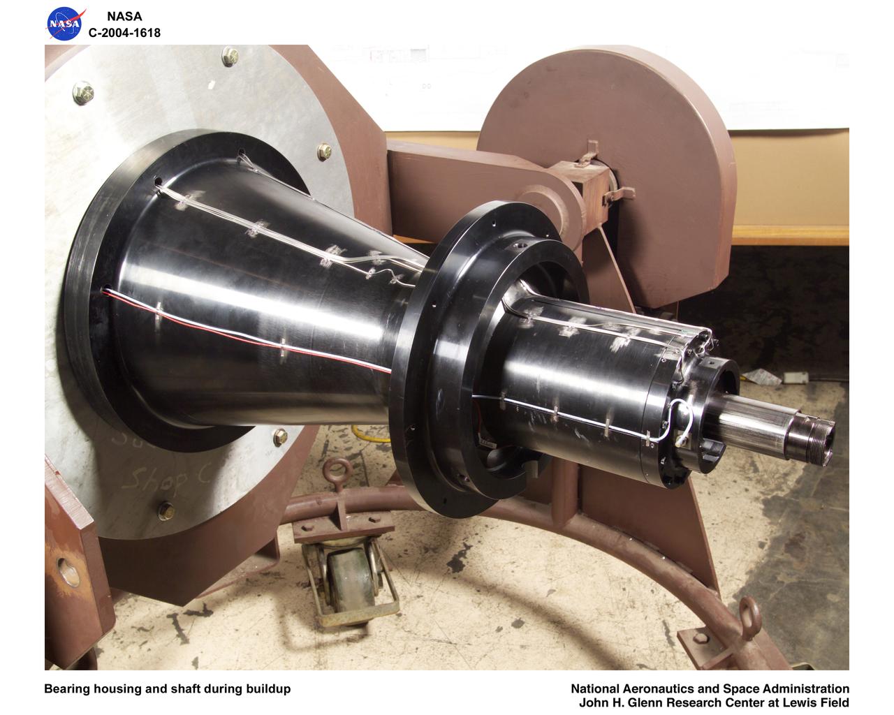
Ultra-Efficient Engine Technology (UEET), Proof of Concept Compressor, Advanced Compressor Casing Treatment testing; bearing housing and shaft during build-up
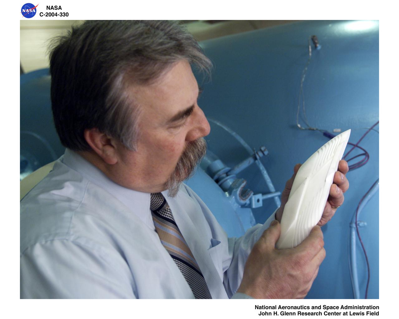
Ultra-Efficient Engine Technology (UEET) Proof of Concept Compressor, Advanced Compressor Casing Treatment testing, First Research Configuration (concentric grooves)
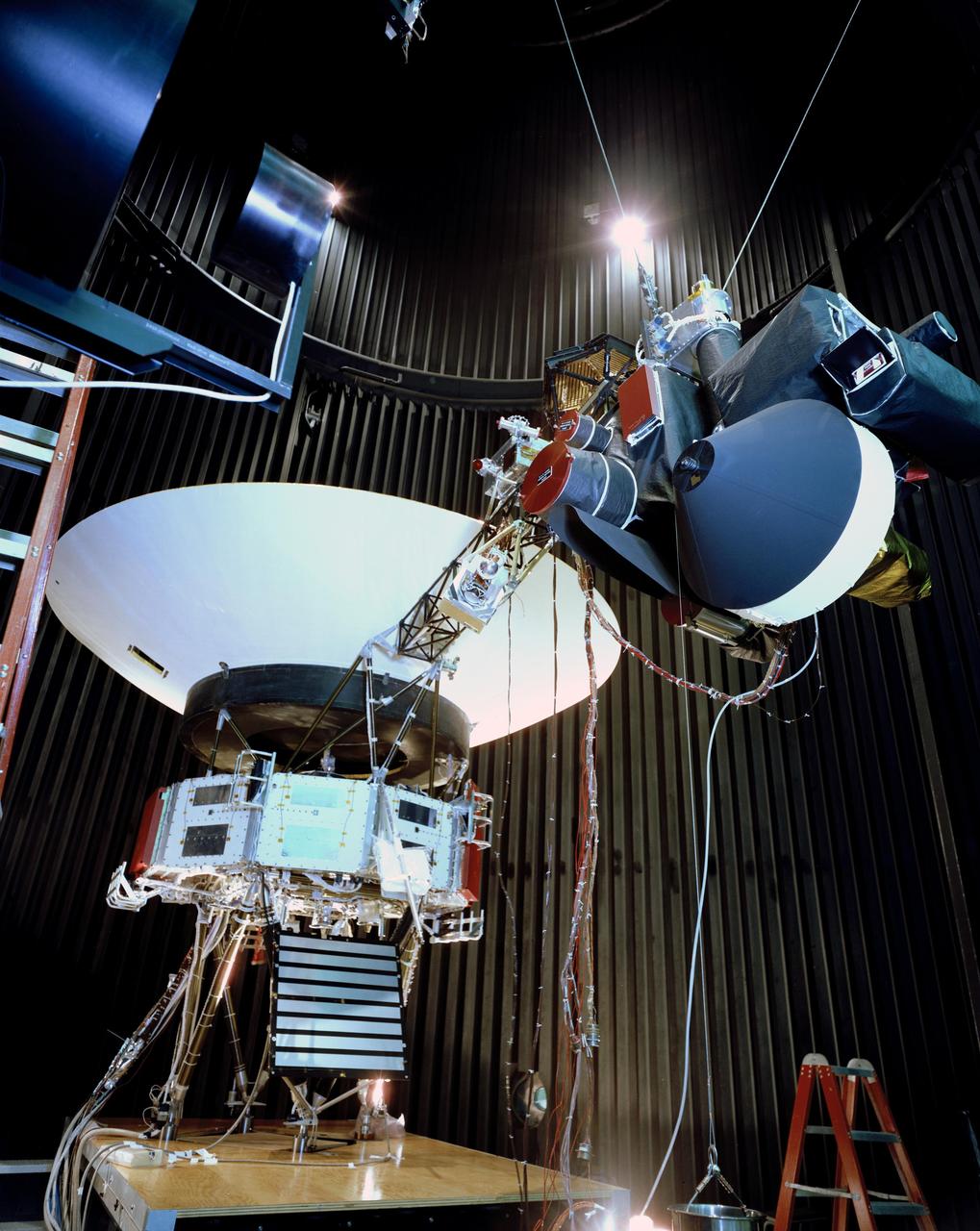
This archival photo shows the Voyager proof test model, which did not fly in space, in the 25-foot space simulator chamber at NASA's Jet Propulsion Laboratory, Pasadena, California, on December 3, 1976. The spacecraft is seen here with its scan platform, which holds several of its science instruments, in the deployed position. https://photojournal.jpl.nasa.gov/catalog/PIA21734
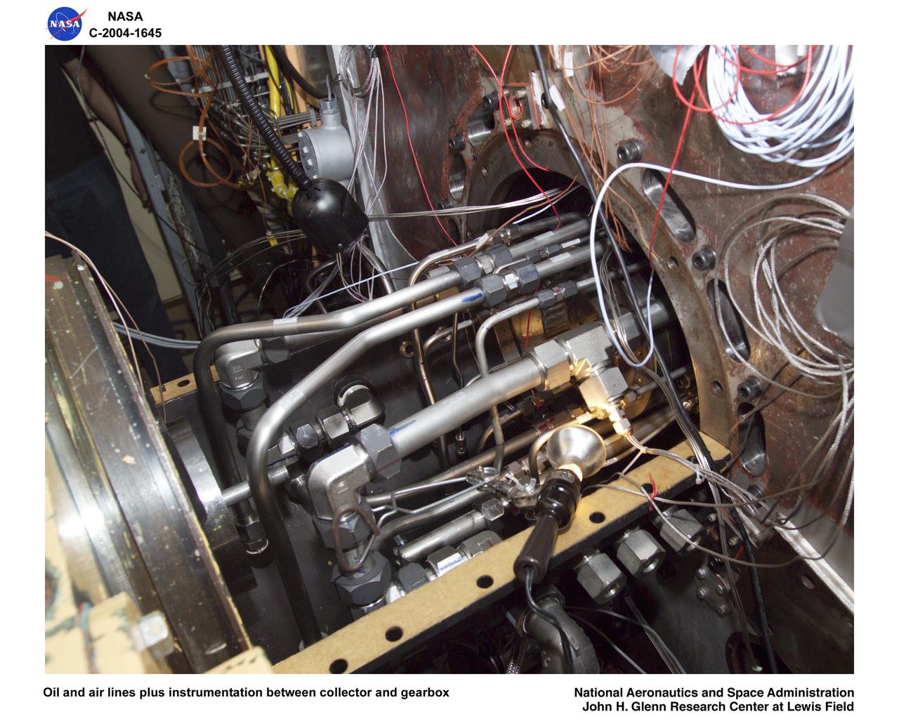
Ultra-Efficient Engine Technology (UEET), Proof of Concept Compressor, Advanced Compressor Casing Treatment testing; oil and air lines plus instrumentation between collector and gearbox
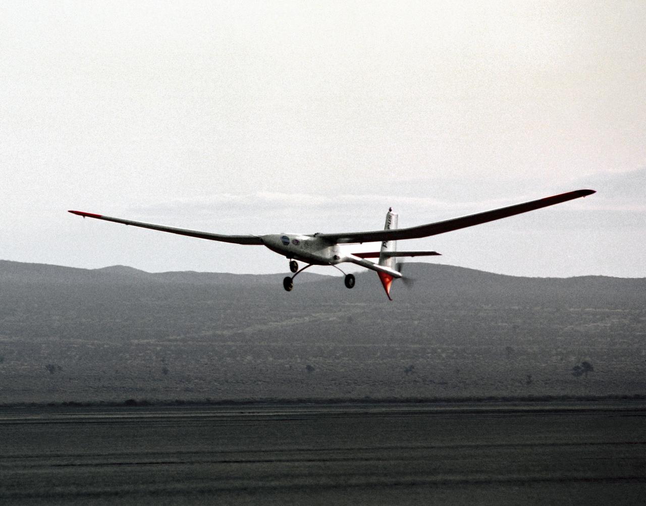
The Perseus proof-of-concept vehicle flies over Rogers Dry Lake at the Dryden Flight Research Center, Edwards, California, to test basic design concepts for the remotely-piloted, high-altitude vehicle.
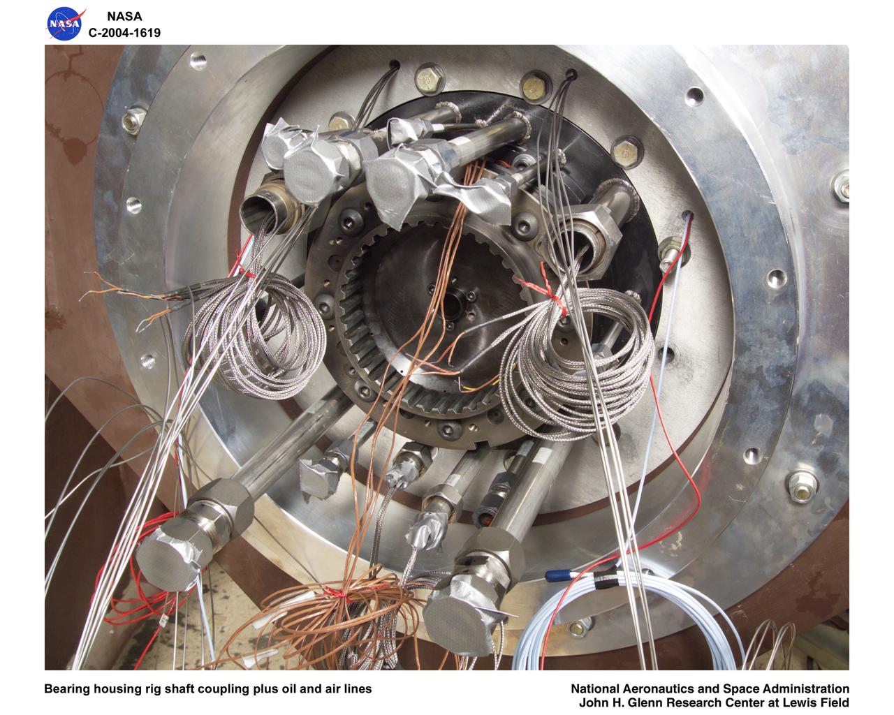
Ultra-Efficient Engine Technology (UEET), Proof of Concept Compressor, Advanced Compressor Casing Treatment testing; bearing housing rig shaft coupling and oil, air lines

Crew members check out the Perseus proof-of-concept vehicle on Rogers Dry Lake, adjacent to the Dryden Flight Research Center, Edwards, California, after a test flight in 1991.
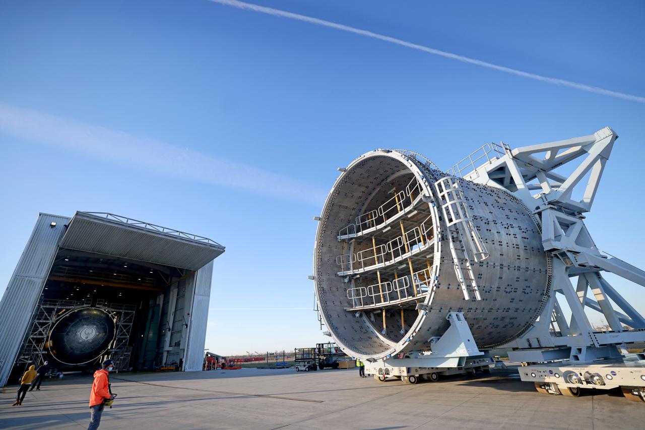
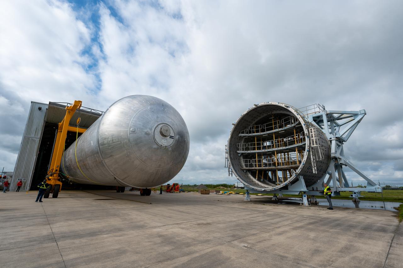
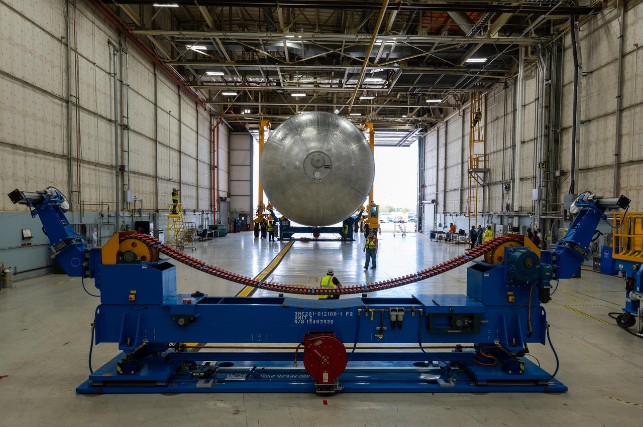
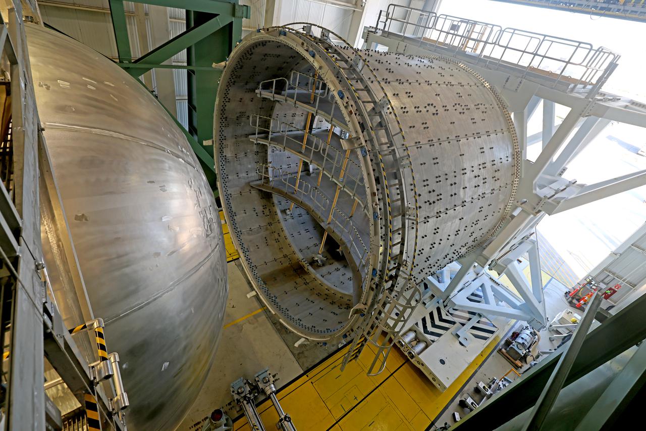
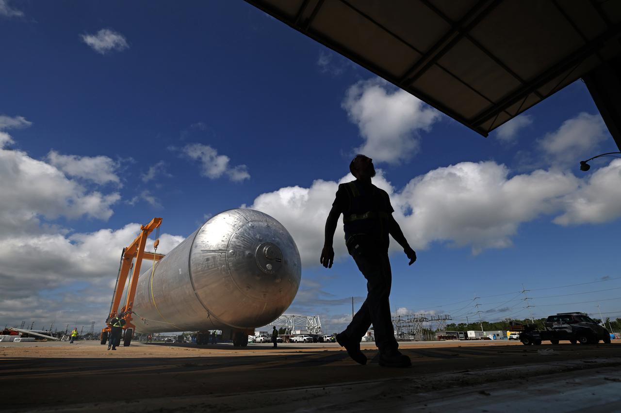
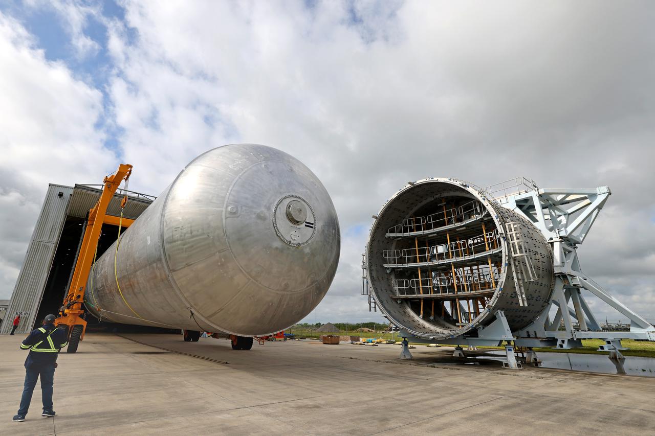
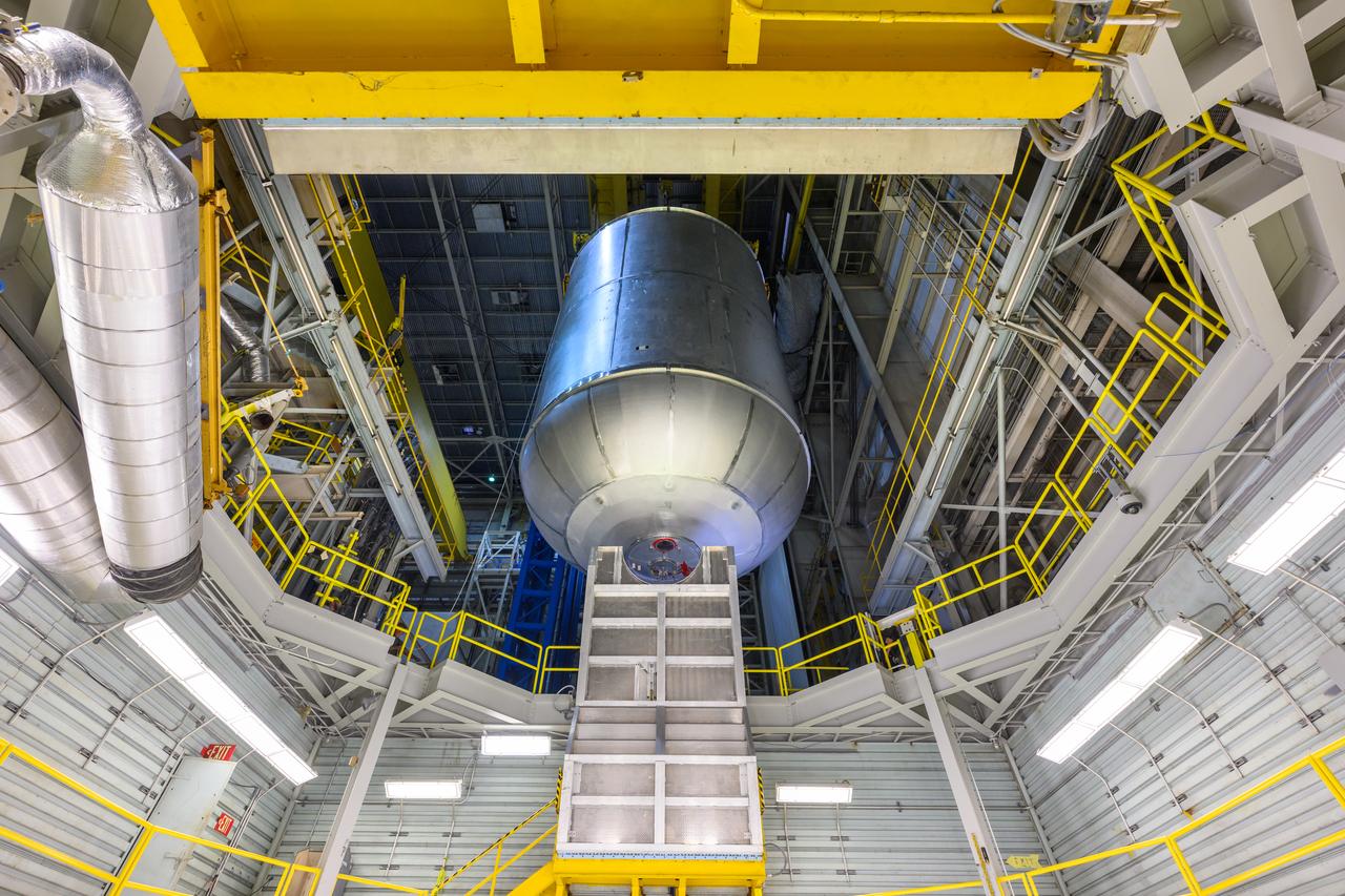
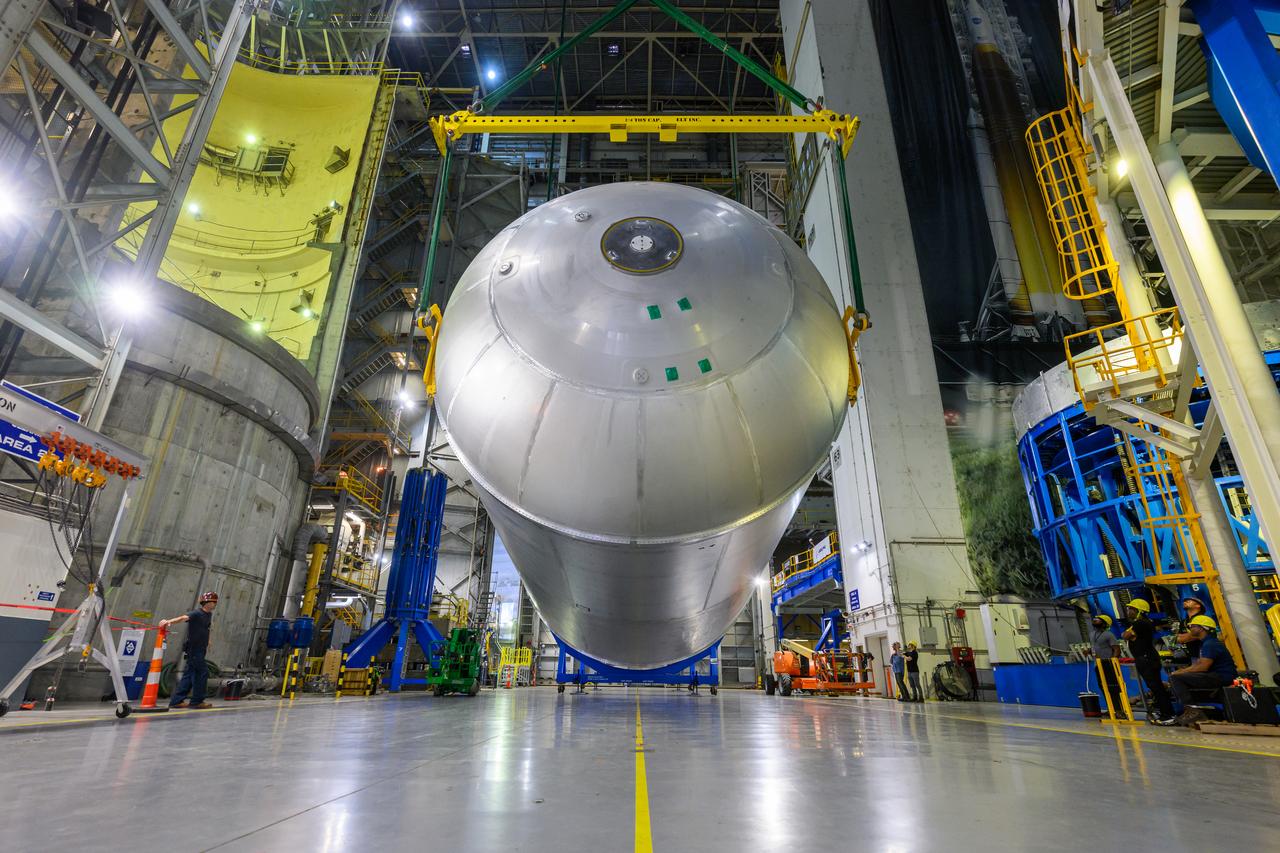
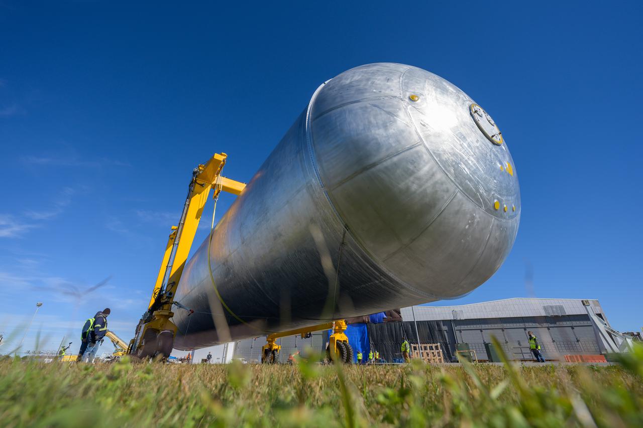
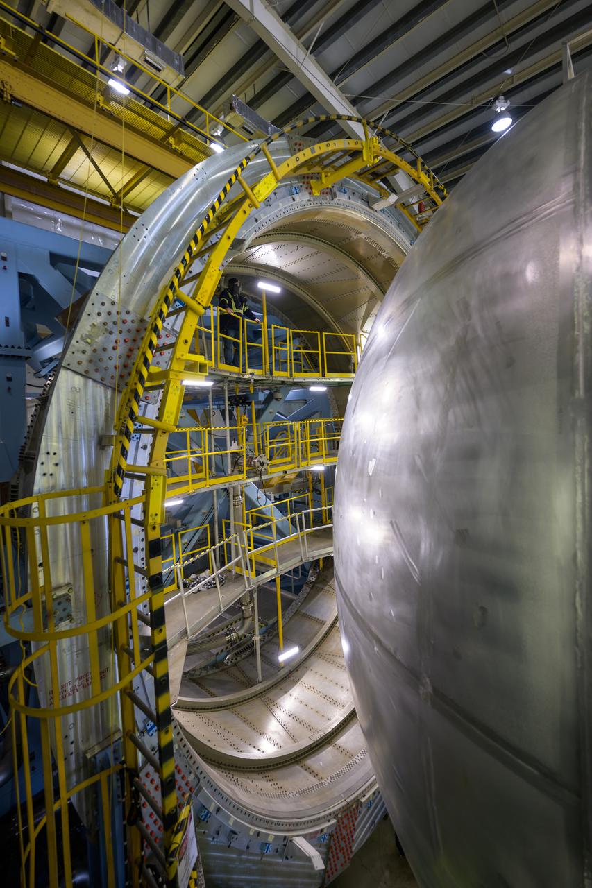
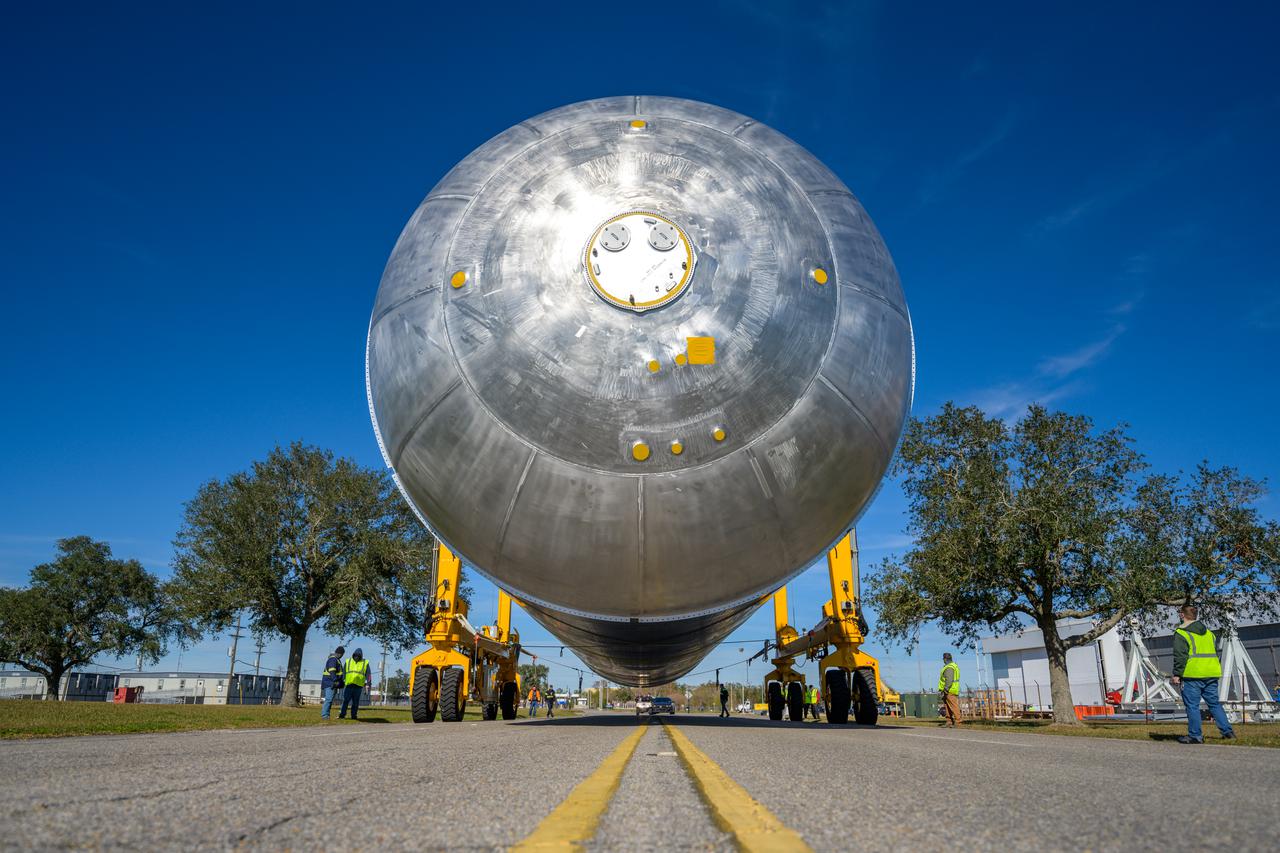
The liquid hydrogen tank that will be part of the Space Launch System rocket’s core stage is being prepared for the Artemis III mission at NASA’s Michoud Assembly Facility in New Orleans. Eventually, the tank will be connected to the engine section that will house the four RS-25 engines. The engine section is still being outfitted, so for this test crews attached an engine section aft simulator during proof testing on January 27, 2022. Once the aft simulator is attached, the LH2 tank undergoes non-destructive evaluation, which will test weld strength and ensure the tank is structurally sound. The SLS core stage is made up of five unique elements: the forward skirt, liquid oxygen tank, intertank, liquid hydrogen tank, and the engine section. The tank holds 537,000 gallons of liquid hydrogen cooled to minus 432 degrees Fahrenheit and sits between the core stage’s intertank and engine section. The liquid hydrogen hardware, along with the liquid oxygen tank, will provide propellant to the four RS-25 engines at the bottom of the core stage to produce more than two million pounds of thrust to help launch the Artemis III mission to the Moon. Together with its four RS-25 engines, the rocket’s massive 212-foot-tall core stage — the largest stage NASA has ever built — and its twin solid rocket boosters will produce 8.8 million pounds of thrust to send NASA’s Orion spacecraft, astronauts and supplies beyond Earth’s orbit to the Moon. Image credit: NASA/Michael DeMocker
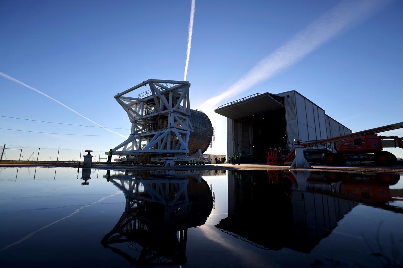
The liquid hydrogen tank that will be part of the Space Launch System rocket’s core stage is being prepared for the Artemis III mission at NASA’s Michoud Assembly Facility in New Orleans. Eventually, the tank will be connected to the engine section that will house the four RS-25 engines. The engine section is still being outfitted, so for this test crews attached an engine section aft simulator during proof testing on January 27, 2022. Once the aft simulator is attached, the LH2 tank undergoes non-destructive evaluation, which will test weld strength and ensure the tank is structurally sound. The SLS core stage is made up of five unique elements: the forward skirt, liquid oxygen tank, intertank, liquid hydrogen tank, and the engine section. The tank holds 537,000 gallons of liquid hydrogen cooled to minus 432 degrees Fahrenheit and sits between the core stage’s intertank and engine section. The liquid hydrogen hardware, along with the liquid oxygen tank, will provide propellant to the four RS-25 engines at the bottom of the core stage to produce more than two million pounds of thrust to help launch the Artemis III mission to the Moon. Together with its four RS-25 engines, the rocket’s massive 212-foot-tall core stage — the largest stage NASA has ever built — and its twin solid rocket boosters will produce 8.8 million pounds of thrust to send NASA’s Orion spacecraft, astronauts and supplies beyond Earth’s orbit to the Moon. Image credit: NASA/Michael DeMocker
The liquid hydrogen tank that will be part of the Space Launch System rocket’s core stage is being prepared for the Artemis III mission at NASA’s Michoud Assembly Facility in New Orleans. Eventually, the tank will be connected to the engine section that will house the RS-25 engines. The engine section is still being outfitted, so for this test crews attached an engine section aft simulator during proof testing on January 27, 2022. Once the aft simulator is attached, the LH2 tank undergoes non-destructive evaluation, which will test weld strength and ensure the tank is structurally sound. The SLS core stage is made up of five unique elements: the forward skirt, liquid oxygen tank, intertank, liquid hydrogen tank, and the engine section. The tank holds 537,000 gallons of liquid hydrogen cooled to minus 432 degrees Fahrenheit and sits between the core stage’s intertank and engine section. The liquid hydrogen hardware, along with the liquid oxygen tank, will provide propellant to the four RS-25 engines at the bottom of the core stage to produce more than two million pounds of thrust to help launch the Artemis III mission to the Moon. Together with its four RS-25 engines, the rocket’s massive 212-foot-tall core stage — the largest stage NASA has ever built — and its twin solid rocket boosters will produce 8.8 million pounds of thrust to send NASA’s Orion spacecraft, astronauts and supplies beyond Earth’s orbit to the Moon. Image credit: NASA/Michael DeMocker
The liquid hydrogen tank that will be part of the Space Launch System rocket’s core stage is being prepared for the Artemis III mission at NASA’s Michoud Assembly Facility in New Orleans. Eventually, the tank will be connected to the engine section that will house the four RS-25 engines. The engine section is still being outfitted, so for this test crews attached an engine section aft simulator during proof testing on January 27, 2022. Once the aft simulator is attached, the LH2 tank undergoes non-destructive evaluation, which will test weld strength and ensure the tank is structurally sound. The SLS core stage is made up of five unique elements: the forward skirt, liquid oxygen tank, intertank, liquid hydrogen tank, and the engine section. The tank holds 537,000 gallons of liquid hydrogen cooled to minus 432 degrees Fahrenheit and sits between the core stage’s intertank and engine section. The liquid hydrogen hardware, along with the liquid oxygen tank, will provide propellant to the four RS-25 engines at the bottom of the core stage to produce more than two million pounds of thrust to help launch the Artemis III mission to the Moon. Together with its four RS-25 engines, the rocket’s massive 212-foot-tall core stage — the largest stage NASA has ever built — and its twin solid rocket boosters will produce 8.8 million pounds of thrust to send NASA’s Orion spacecraft, astronauts and supplies beyond Earth’s orbit to the Moon. Image credit: NASA/Michael DeMocker
The liquid hydrogen tank that will be part of the Space Launch System rocket’s core stage is being prepared for the Artemis III mission at NASA’s Michoud Assembly Facility in New Orleans. Eventually, the tank will be connected to the engine section that will house the four RS-25 engines. The engine section is still being outfitted, so for this test crews attached an engine section aft simulator during proof testing on January 27, 2022. Once the aft simulator is attached, the LH2 tank undergoes non-destructive evaluation, which will test weld strength and ensure the tank is structurally sound. The SLS core stage is made up of five unique elements: the forward skirt, liquid oxygen tank, intertank, liquid hydrogen tank, and the engine section. The tank holds 537,000 gallons of liquid hydrogen cooled to minus 432 degrees Fahrenheit and sits between the core stage’s intertank and engine section. The liquid hydrogen hardware, along with the liquid oxygen tank, will provide propellant to the four RS-25 engines at the bottom of the core stage to produce more than two million pounds of thrust to help launch the Artemis III mission to the Moon. Together with its four RS-25 engines, the rocket’s massive 212-foot-tall core stage — the largest stage NASA has ever built — and its twin solid rocket boosters will produce 8.8 million pounds of thrust to send NASA’s Orion spacecraft, astronauts and supplies beyond Earth’s orbit to the Moon. Image credit: NASA/Michael DeMocker
Mechanical engineering and integration technician, Lucas Keim, holds up a piece of ground support equipment during a proof test at Goddard Space Flight Center, Greenbelt Md., June 22, 2023. This photo has been reviewed by OSAM1 project management and the Export Control Office and is released for public view. NASA/Mike Guinto
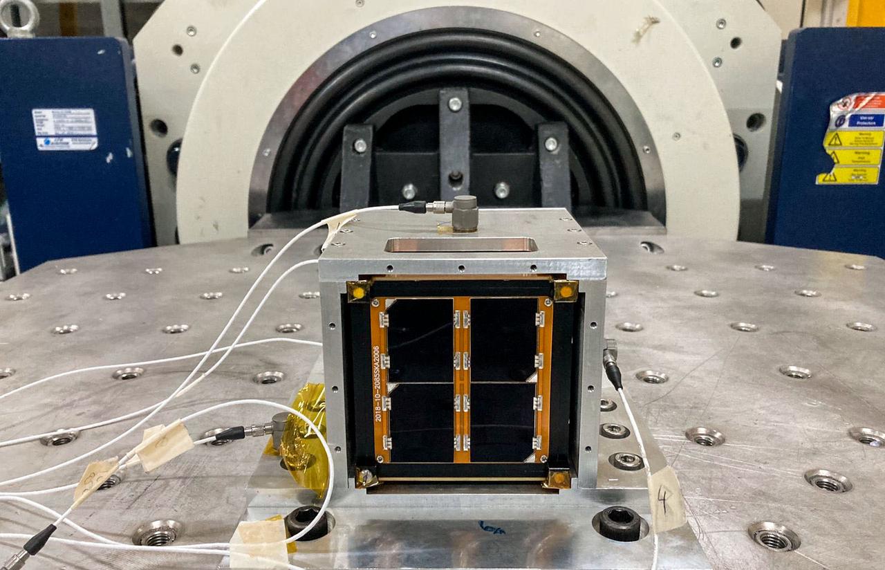
jsc2022e068265 (3/1/2022) --- A preflight view of the Surya Satellite-1 (SS-1) during Vibration Testing. The Surya Satellite-1 (SS-1) is the first Indonesian nanosatellite developed by university students at Surya University. SS-1 tests a satellite telecommunication system to serve amateur radio stations, and serves as a proof of concept of sensoric information transfer in rural areas for disaster mitigation application. Image Courtesy of The SS-1 Team.

jsc2022e068261 (11/1/2021) --- The Surya Satellite-1 and its developer team after Vibration Testing, shown left to right: Afiq, Roberto, Setra, Suhan, Hery, Zulfa. The Surya Satellite-1 (SS-1) is the first Indonesian nanosatellite developed by university students at Surya University. SS-1 tests a satellite telecommunication system to serve amateur radio stations, and serves as a proof of concept of sensoric information transfer in rural areas for disaster mitigation application. Image Courtesy of The SS-1 Team.
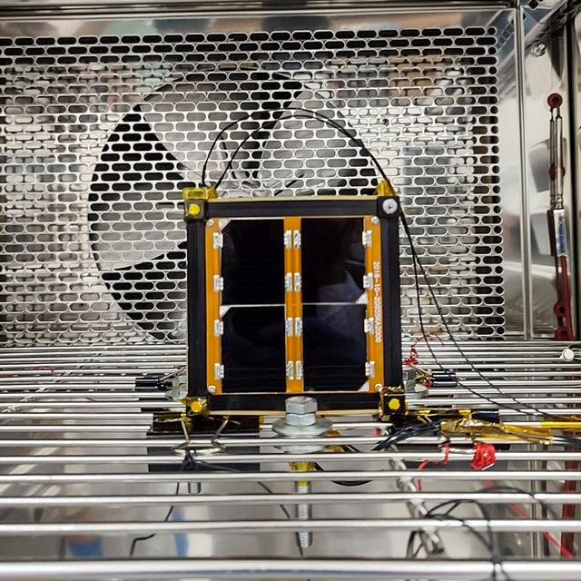
jsc2022e068264 (12/1/2021) --- A preflight view of the Surya Satellite-1 (SS-1) during Thermal Testing. The Surya Satellite-1 (SS-1) is the first Indonesian nanosatellite developed by university students at Surya University. SS-1 tests a satellite telecommunication system to serve amateur radio stations, and serves as a proof of concept of sensoric information transfer in rural areas for disaster mitigation application. Image Courtesy of The SS-1 Team.
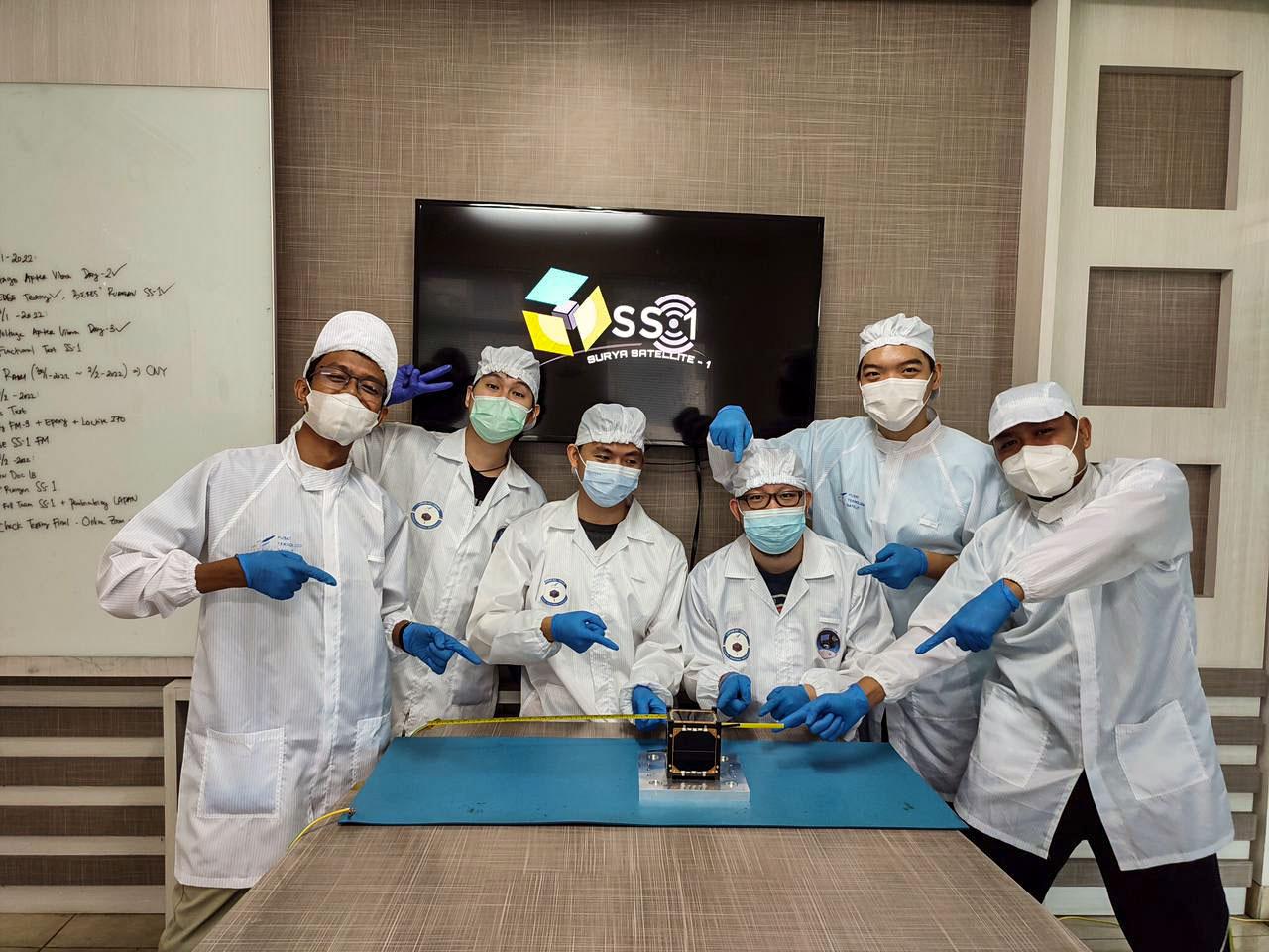
jsc2022e068260 (11/1/2021) --- The Surya Satellite-1 and its Developer Team After Deployment Testing, shown left to right: Zulfa, Hery, Setra, Roberto, Suhan, Afiq. The Surya Satellite-1 (SS-1) is the first Indonesian nanosatellite developed by university students at Surya University. SS-1 tests a satellite telecommunication system to serve amateur radio stations, and serves as a proof of concept of sensoric information transfer in rural areas for disaster mitigation application. Image Courtesy of The SS-1 Team.
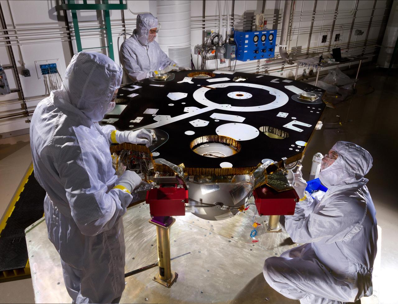
Technicians in a Lockheed Martin clean room near Denver prepare NASA's InSight Mars lander for propulsion proof and leak testing on Oct. 31, 2014. Following the test, the lander was moved to another clean room for the start of the mission's assembly, test and launch operations (ATLO) phase. The assembly portion of ATLO will last about six months. The InSight mission (for Interior Exploration using Seismic Investigations, Geodesy and Heat Transport) is scheduled to launch in March 2016 and land on Mars six months later. It will investigate processes that formed and shaped Mars and will help scientists better understand the evolution of our inner solar system's rocky planets, including Earth. Note: After thorough examination, NASA managers have decided to suspend the planned March 2016 launch of the Interior Exploration using Seismic Investigations Geodesy and Heat Transport (InSight) mission. The decision follows unsuccessful attempts to repair a leak in a section of the prime instrument in the science payload. http://photojournal.jpl.nasa.gov/catalog/PIA18884
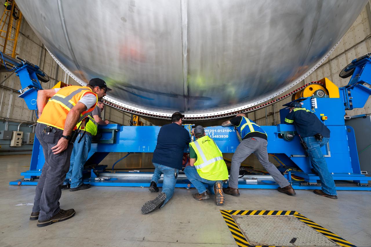
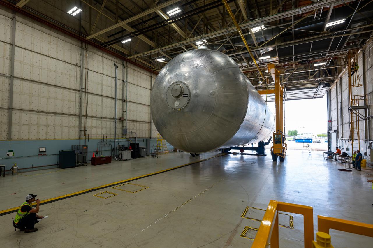
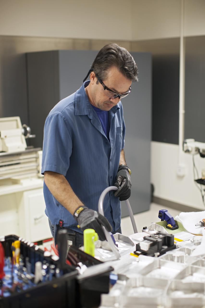
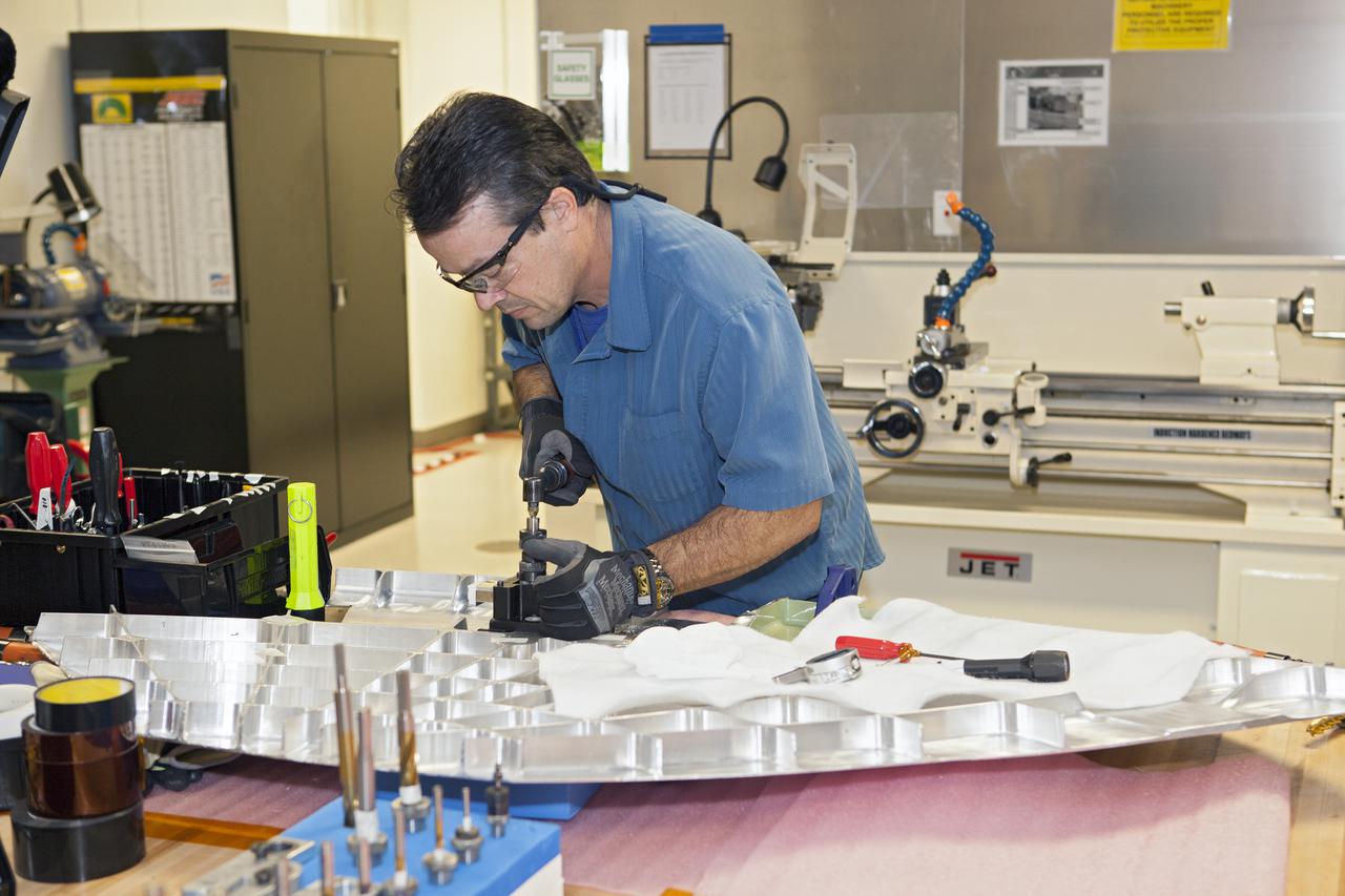
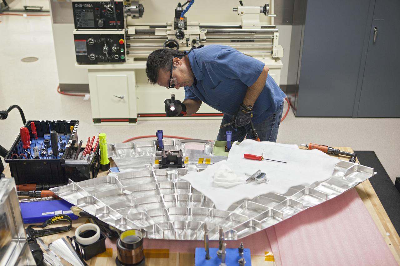
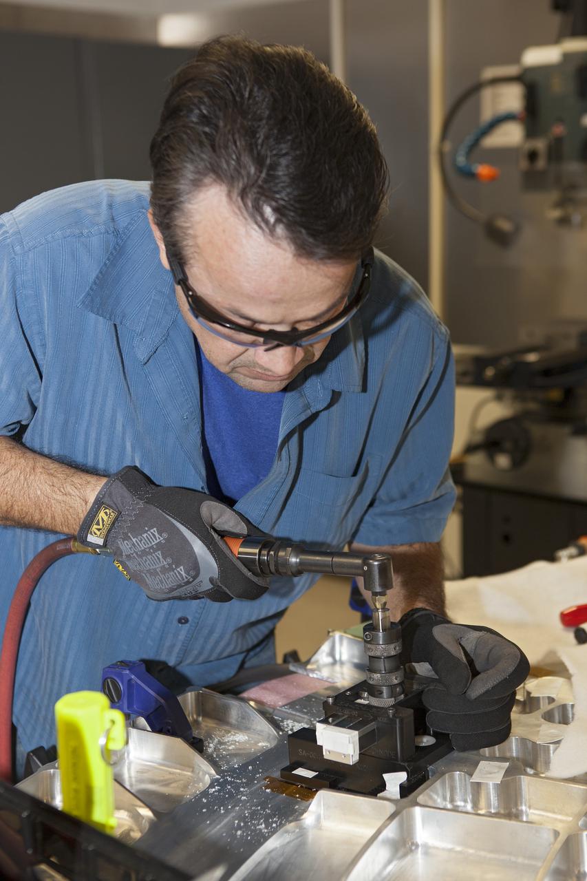
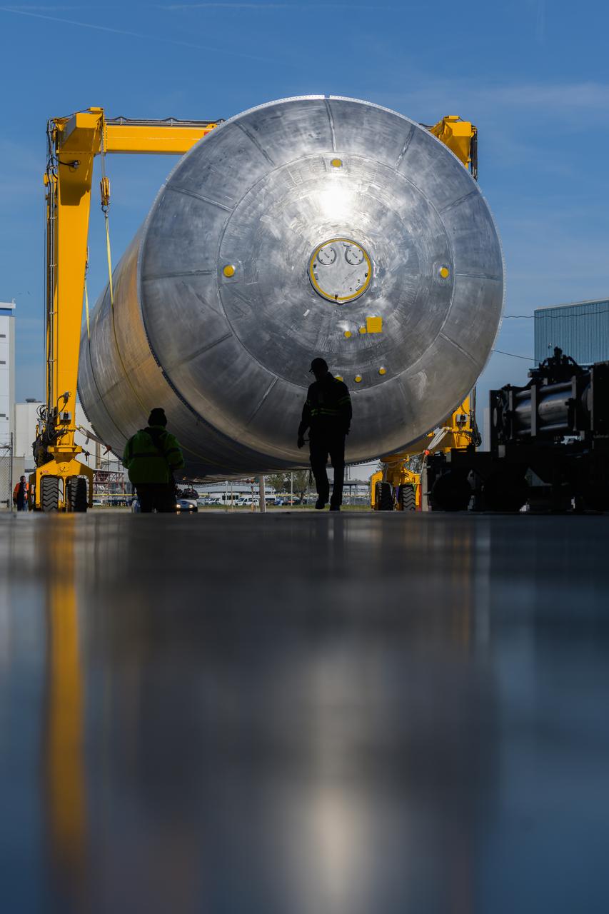
The core stage liquid hydrogen tank for the Artemis III mission completed proof testing, and technicians returned it to the main factory building at NASA’s Michoud Assembly Facility in New Orleans where it will undergo more outfitting. As part of proof testing, technicians apply a simple soap solution and check for leaks by observing any bubble formation on the welds. The technician removed the bubble solution with distilled water and then dried the area of application to prevent corrosion. To build the Space Launch System (SLS) rocket’s 130-foot core stage liquid hydrogen tank, engineers use robotic tools to weld five-barrel segments. This process results in a tank with around 1,900 feet, or more than six football fields, of welds that must be tested by hand. After the leak tests, the core stage lead, Boeing, pressurized the SLS tank to further ensure there were no leaks. After it passed proof testing, technicians moved the Artemis III liquid hydrogen tank to Michoud’s main factory. Soon, the technicians will prime and apply a foam-based thermal protection system that protects the tank during launch. Later, the tank will be joined with other parts of the core stage to form the entire 212-foot rocket stage with its four RS-25 engines that produce 2 million pounds of thrust to help launch the rocket. Artemis III will land the first astronauts on the lunar surface. Photographed on Monday, April 18, 2022. Image credit: NASA/Michael DeMocker
The core stage liquid hydrogen tank for the Artemis III mission completed proof testing, and technicians returned it to the main factory building at NASA’s Michoud Assembly Facility in New Orleans where it will undergo more outfitting. As part of proof testing, technicians apply a simple soap solution and check for leaks by observing any bubble formation on the welds. The technician removed the bubble solution with distilled water and then dried the area of application to prevent corrosion. To build the Space Launch System (SLS) rocket’s 130-foot core stage liquid hydrogen tank, engineers use robotic tools to weld five-barrel segments. This process results in a tank with around 1,900 feet, or more than six football fields, of welds that must be tested by hand. After the leak tests, the core stage lead, Boeing, pressurized the SLS tank to further ensure there were no leaks. After it passed proof testing, technicians moved the Artemis III liquid hydrogen tank to Michoud’s main factory. Soon, the technicians will prime and apply a foam-based thermal protection system that protects the tank during launch. Later, the tank will be joined with other parts of the core stage to form the entire 212-foot rocket stage with its four RS-25 engines that produce 2 million pounds of thrust to help launch the rocket. Artemis III will land the first astronauts on the lunar surface. Photographed on Monday, April 18, 2022.
The core stage liquid hydrogen tank for the Artemis III mission completed proof testing, and technicians returned it to the main factory building at NASA’s Michoud Assembly Facility in New Orleans where it will undergo more outfitting. As part of proof testing, technicians apply a simple soap solution and check for leaks by observing any bubble formation on the welds. The technician removed the bubble solution with distilled water and then dried the area of application to prevent corrosion. To build the Space Launch System (SLS) rocket’s 130-foot core stage liquid hydrogen tank, engineers use robotic tools to weld five-barrel segments. This process results in a tank with around 1,900 feet, or more than six football fields, of welds that must be tested by hand. After the leak tests, the core stage lead, Boeing, pressurized the SLS tank to further ensure there were no leaks. After it passed proof testing, technicians moved the Artemis III liquid hydrogen tank to Michoud’s main factory. Soon, the technicians will prime and apply a foam-based thermal protection system that protects the tank during launch. Later, the tank will be joined with other parts of the core stage to form the entire 212-foot rocket stage with its four RS-25 engines that produce 2 million pounds of thrust to help launch the rocket. Artemis III will land the first astronauts on the lunar surface. Photographed on Monday, April 18, 2022. Image credit: NASA/Michael DeMocker
The core stage liquid hydrogen tank for the Artemis III mission completed proof testing, and technicians returned it to the main factory building at NASA’s Michoud Assembly Facility in New Orleans where it will undergo more outfitting. As part of proof testing, technicians apply a simple soap solution and check for leaks by observing any bubble formation on the welds. The technician removed the bubble solution with distilled water and then dried the area of application to prevent corrosion. To build the Space Launch System (SLS) rocket’s 130-foot core stage liquid hydrogen tank, engineers use robotic tools to weld five-barrel segments. This process results in a tank with around 1,900 feet, or more than six football fields, of welds that must be tested by hand. After the leak tests, the core stage lead, Boeing, pressurized the SLS tank to further ensure there were no leaks. After it passed proof testing, technicians moved the Artemis III liquid hydrogen tank to Michoud’s main factory. Soon, the technicians will prime and apply a foam-based thermal protection system that protects the tank during launch. Later, the tank will be joined with other parts of the core stage to form the entire 212-foot rocket stage with its four RS-25 engines that produce 2 million pounds of thrust to help launch the rocket. Artemis III will land the first astronauts on the lunar surface. Photographed on Monday, April 18, 2022. Image credit: NASA/Michael DeMocker
The core stage liquid hydrogen tank for the Artemis III mission completed proof testing, and technicians returned it to the main factory building at NASA’s Michoud Assembly Facility in New Orleans where it will undergo more outfitting. As part of proof testing, technicians apply a simple soap solution and check for leaks by observing any bubble formation on the welds. The technician removed the bubble solution with distilled water and then dried the area of application to prevent corrosion. To build the Space Launch System (SLS) rocket’s 130-foot core stage liquid hydrogen tank, engineers use robotic tools to weld five-barrel segments. This process results in a tank with around 1,900 feet, or more than six football fields, of welds that must be tested by hand. After the leak tests, the core stage lead, Boeing, pressurized the SLS tank to further ensure there were no leaks. After it passed proof testing, technicians moved the Artemis III liquid hydrogen tank to Michoud’s main factory. Soon, the technicians will prime and apply a foam-based thermal protection system that protects the tank during launch. Later, the tank will be joined with other parts of the core stage to form the entire 212-foot rocket stage with its four RS-25 engines that produce 2 million pounds of thrust to help launch the rocket. Artemis III will land the first astronauts on the lunar surface. Photographed on Monday, April 18, 2022. Image credit: NASA/Michael DeMocker
The core stage liquid hydrogen tank for the Artemis III mission completed proof testing, and technicians returned it to the main factory building at NASA’s Michoud Assembly Facility in New Orleans where it will undergo more outfitting. As part of proof testing, technicians apply a simple soap solution and check for leaks by observing any bubble formation on the welds. The technician removed the bubble solution with distilled water and then dried the area of application to prevent corrosion. To build the Space Launch System (SLS) rocket’s 130-foot core stage liquid hydrogen tank, engineers use robotic tools to weld five-barrel segments. This process results in a tank with around 1,900 feet, or more than six football fields, of welds that must be tested by hand. After the leak tests, the core stage lead, Boeing, pressurized the SLS tank to further ensure there were no leaks. After it passed proof testing, technicians moved the Artemis III liquid hydrogen tank to Michoud’s main factory. Soon, the technicians will prime and apply a foam-based thermal protection system that protects the tank during launch. Later, the tank will be joined with other parts of the core stage to form the entire 212-foot rocket stage with its four RS-25 engines that produce 2 million pounds of thrust to help launch the rocket. Artemis III will land the first astronauts on the lunar surface. Photographed on Monday, April 18, 2022.
The core stage liquid hydrogen tank for the Artemis III mission completed proof testing, and technicians returned it to the main factory building at NASA’s Michoud Assembly Facility in New Orleans where it will undergo more outfitting. As part of proof testing, technicians apply a simple soap solution and check for leaks by observing any bubble formation on the welds. The technician removed the bubble solution with distilled water and then dried the area of application to prevent corrosion. To build the Space Launch System (SLS) rocket’s 130-foot core stage liquid hydrogen tank, engineers use robotic tools to weld five-barrel segments. This process results in a tank with around 1,900 feet, or more than six football fields, of welds that must be tested by hand. After the leak tests, the core stage lead, Boeing, pressurized the SLS tank to further ensure there were no leaks. After it passed proof testing, technicians moved the Artemis III liquid hydrogen tank to Michoud’s main factory. Soon, the technicians will prime and apply a foam-based thermal protection system that protects the tank during launch. Later, the tank will be joined with other parts of the core stage to form the entire 212-foot rocket stage with its four RS-25 engines that produce 2 million pounds of thrust to help launch the rocket. Artemis III will land the first astronauts on the lunar surface. Photographed on Monday, April 18, 2022.

The core stage liquid hydrogen tank for the Artemis III mission completed proof testing, and technicians returned it to the main factory building at NASA’s Michoud Assembly Facility in New Orleans where it will undergo more outfitting. As part of proof testing, technicians apply a simple soap solution and check for leaks by observing any bubble formation on the welds. The technician removed the bubble solution with distilled water and then dried the area of application to prevent corrosion. To build the Space Launch System (SLS) rocket’s 130-foot core stage liquid hydrogen tank, engineers use robotic tools to weld five-barrel segments. This process results in a tank with around 1,900 feet, or more than six football fields, of welds that must be tested by hand. After the leak tests, the core stage lead, Boeing, pressurized the SLS tank to further ensure there were no leaks. After it passed proof testing, technicians moved the Artemis III liquid hydrogen tank to Michoud’s main factory. Soon, the technicians will prime and apply a foam-based thermal protection system that protects the tank during launch. Later, the tank will be joined with other parts of the core stage to form the entire 212-foot rocket stage with its four RS-25 engines that produce 2 million pounds of thrust to help launch the rocket. Artemis III will land the first astronauts on the lunar surface. Photographed on Monday, April 18, 2022.
The core stage liquid hydrogen tank for the Artemis III mission completed proof testing, and technicians returned it to the main factory building at NASA’s Michoud Assembly Facility in New Orleans where it will undergo more outfitting. As part of proof testing, technicians apply a simple soap solution and check for leaks by observing any bubble formation on the welds. The technician removed the bubble solution with distilled water and then dried the area of application to prevent corrosion. To build the Space Launch System (SLS) rocket’s 130-foot core stage liquid hydrogen tank, engineers use robotic tools to weld five-barrel segments. This process results in a tank with around 1,900 feet, or more than six football fields, of welds that must be tested by hand. After the leak tests, the core stage lead, Boeing, pressurized the SLS tank to further ensure there were no leaks. After it passed proof testing, technicians moved the Artemis III liquid hydrogen tank to Michoud’s main factory. Soon, the technicians will prime and apply a foam-based thermal protection system that protects the tank during launch. Later, the tank will be joined with other parts of the core stage to form the entire 212-foot rocket stage with its four RS-25 engines that produce 2 million pounds of thrust to help launch the rocket. Artemis III will land the first astronauts on the lunar surface. Photographed on Monday, April 18, 2022. Image credit: NASA/Michael DeMocker
The core stage liquid hydrogen tank for the Artemis III mission completed proof testing, and technicians returned it to the main factory building at NASA’s Michoud Assembly Facility in New Orleans where it will undergo more outfitting. As part of proof testing, technicians apply a simple soap solution and check for leaks by observing any bubble formation on the welds. The technician removed the bubble solution with distilled water and then dried the area of application to prevent corrosion. To build the Space Launch System (SLS) rocket’s 130-foot core stage liquid hydrogen tank, engineers use robotic tools to weld five-barrel segments. This process results in a tank with around 1,900 feet, or more than six football fields, of welds that must be tested by hand. After the leak tests, the core stage lead, Boeing, pressurized the SLS tank to further ensure there were no leaks. After it passed proof testing, technicians moved the Artemis III liquid hydrogen tank to Michoud’s main factory. Soon, the technicians will prime and apply a foam-based thermal protection system that protects the tank during launch. Later, the tank will be joined with other parts of the core stage to form the entire 212-foot rocket stage with its four RS-25 engines that produce 2 million pounds of thrust to help launch the rocket. Artemis III will land the first astronauts on the lunar surface. Photographed on Monday, April 18, 2022. Image credit: NASA/Michael DeMocker
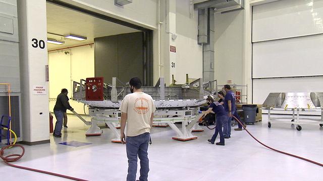
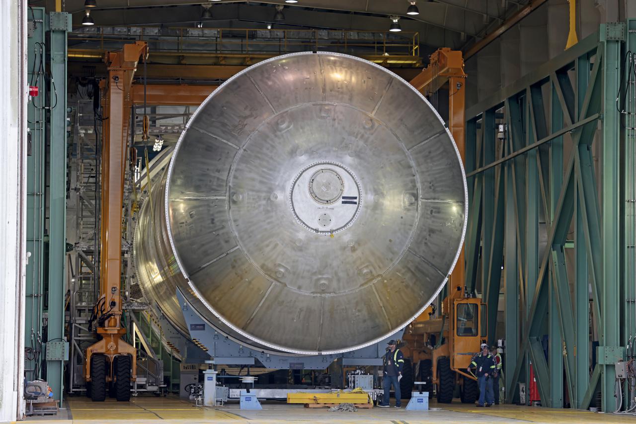
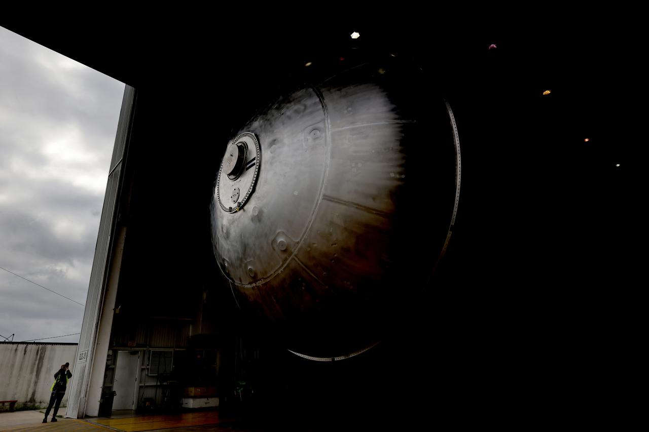
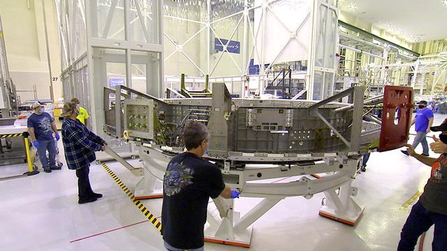
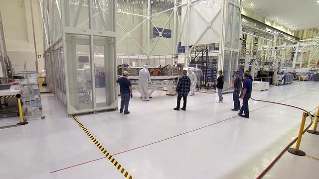
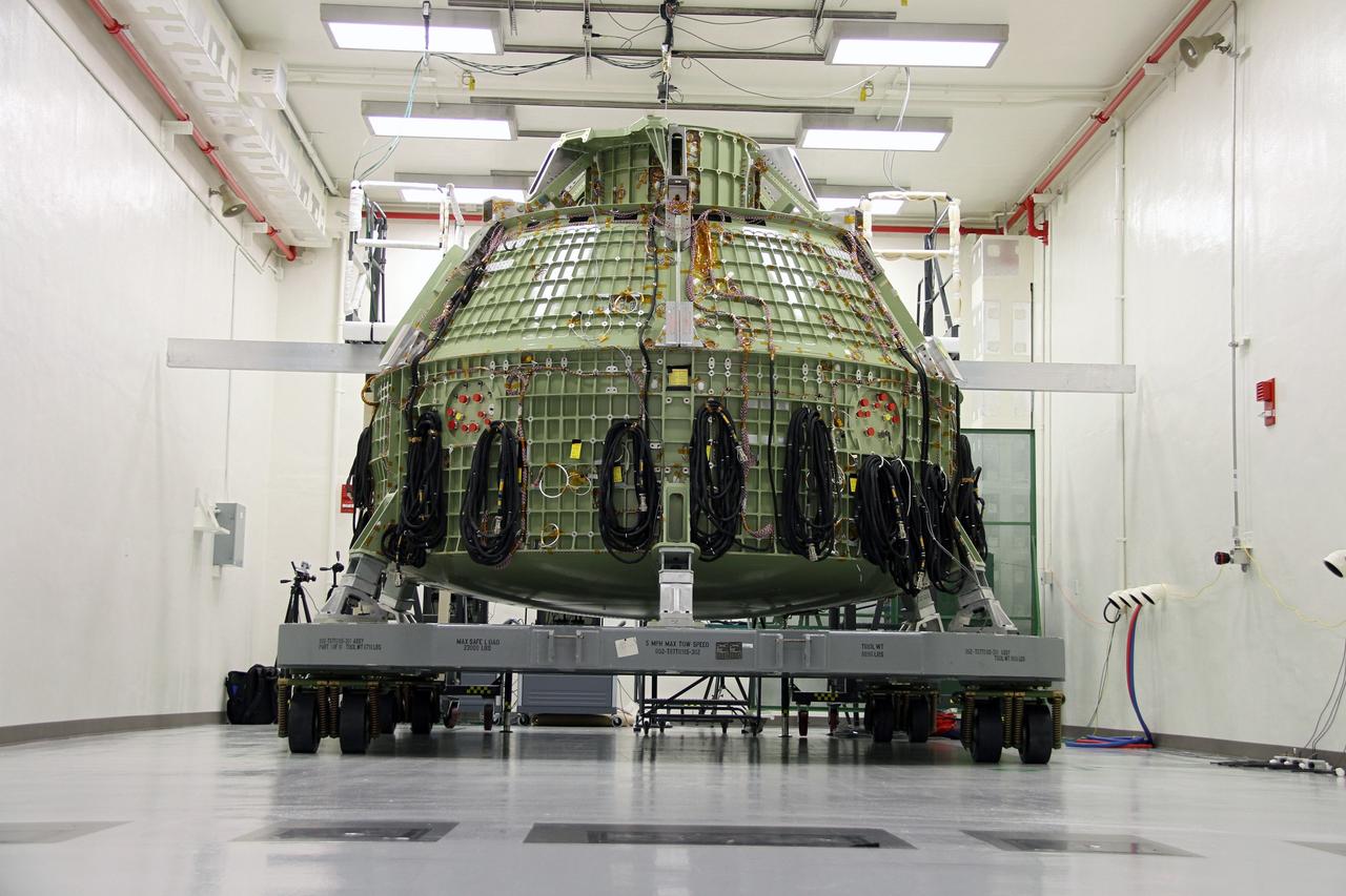
Inside the Neil Armstrong Operations and Checkout Building at NASA's Kennedy Space Center in Florida, the Artemis II crew module adapter (CMA) is being relocated from the clean room to the Pressure Proof Cell for additional testing and maintenance. The CMA connects the crew module to the service module. Artemis II is the first crewed mission in a series of missions to the Moon and on to Mars. Artemis II will confirm all of the Orion spacecraft’s systems operate as designed in the actual environment of deep space with astronauts aboard.
Inside the Neil Armstrong Operations and Checkout Building at NASA's Kennedy Space Center in Florida, the Artemis II crew module adapter (CMA) is being relocated from the clean room to the Pressure Proof Cell for additional testing and maintenance. The CMA connects the crew module to the service module. Artemis II is the first crewed mission in a series of missions to the Moon and on to Mars. Artemis II will confirm all of the Orion spacecraft’s systems operate as designed in the actual environment of deep space with astronauts aboard.
Inside the Neil Armstrong Operations and Checkout Building at NASA's Kennedy Space Center in Florida, the Artemis II crew module adapter (CMA) is being relocated from the clean room to the Pressure Proof Cell for additional testing and maintenance. The CMA connects the crew module to the service module. Artemis II is the first crewed mission in a series of missions to the Moon and on to Mars. Artemis II will confirm all of the Orion spacecraft’s systems operate as designed in the actual environment of deep space with astronauts aboard.

jsc2022e068262 (5/1/2022) --- A view of the SS-1 Team during the JAXA Safety Review. The Surya Satellite-1 (SS-1) is the first Indonesian nanosatellite developed by university students at Surya University. SS-1 tests a satellite telecommunication system to serve amateur radio stations, and serves as a proof of concept of sensoric information transfer in rural areas for disaster mitigation application. Image Courtesy of The SS-1 Team.
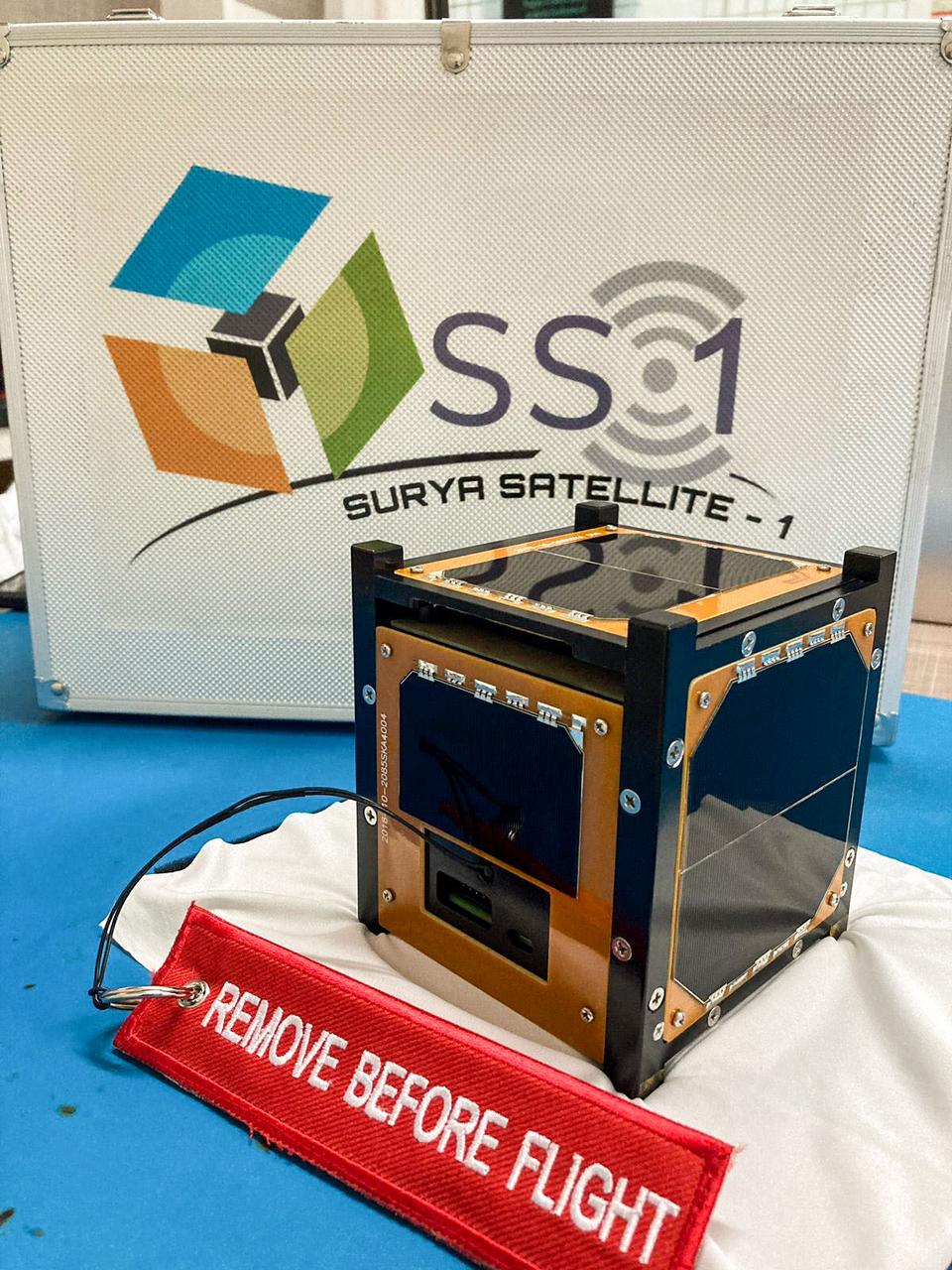
jsc2022e068263 (5/1/2022) --- A preflight view of the Surya Satellite-1 (SS-1) Flight Model. The Surya Satellite-1 (SS-1) is the first Indonesian nanosatellite developed by university students at Surya University. SS-1 tests a satellite telecommunication system to serve amateur radio stations, and serves as a proof of concept of sensoric information transfer in rural areas for disaster mitigation application. Image Courtesy of The SS-1 Team.
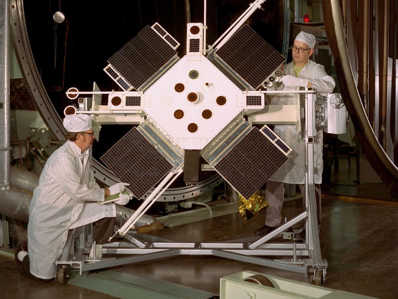
Researchers examine the Space Plasma-High Voltage Interaction Experiment (SPHINX) satellite in the Electric Propulsion Laboratory at the National Aeronautics and Space Administration (NASA) Lewis Research Center. Lewis’ Spacecraft Technology Division designed SPHINX to study the electrical interaction of its experimental surfaces with space plasma. They sought to determine if higher orbits would improve the transmission quality of communications satellites. Robert Lovell, the Project Manager, oversaw vibrational and plasma simulation testing of the satellite in the Electric Propulsion Laboratory, seen here. SPHINX was an add-on payload for the first Titan/Centaur proof launch in early 1974. Lewis successfully managed the Centaur Program since 1962, but this would be the first Centaur launch with a Titan booster. Since the proof test did not have a scheduled payload, the Lewis-designed SPHINX received a free ride. The February 11, 1974 launch, however, proved to be one of the Launch Vehicle Division’s lowest days. Twelve minutes after the vehicle departed the launch pad, the booster and Centaur separated as designed, but Centaur’s two RL-10 engines failed to ignite. The launch pad safety officer destroyed the vehicle, and SPHINX never made it into orbit. Overall Centaur has an excellent success rate, but the failed SPHINX launch attempt caused deep disappointment across the center.
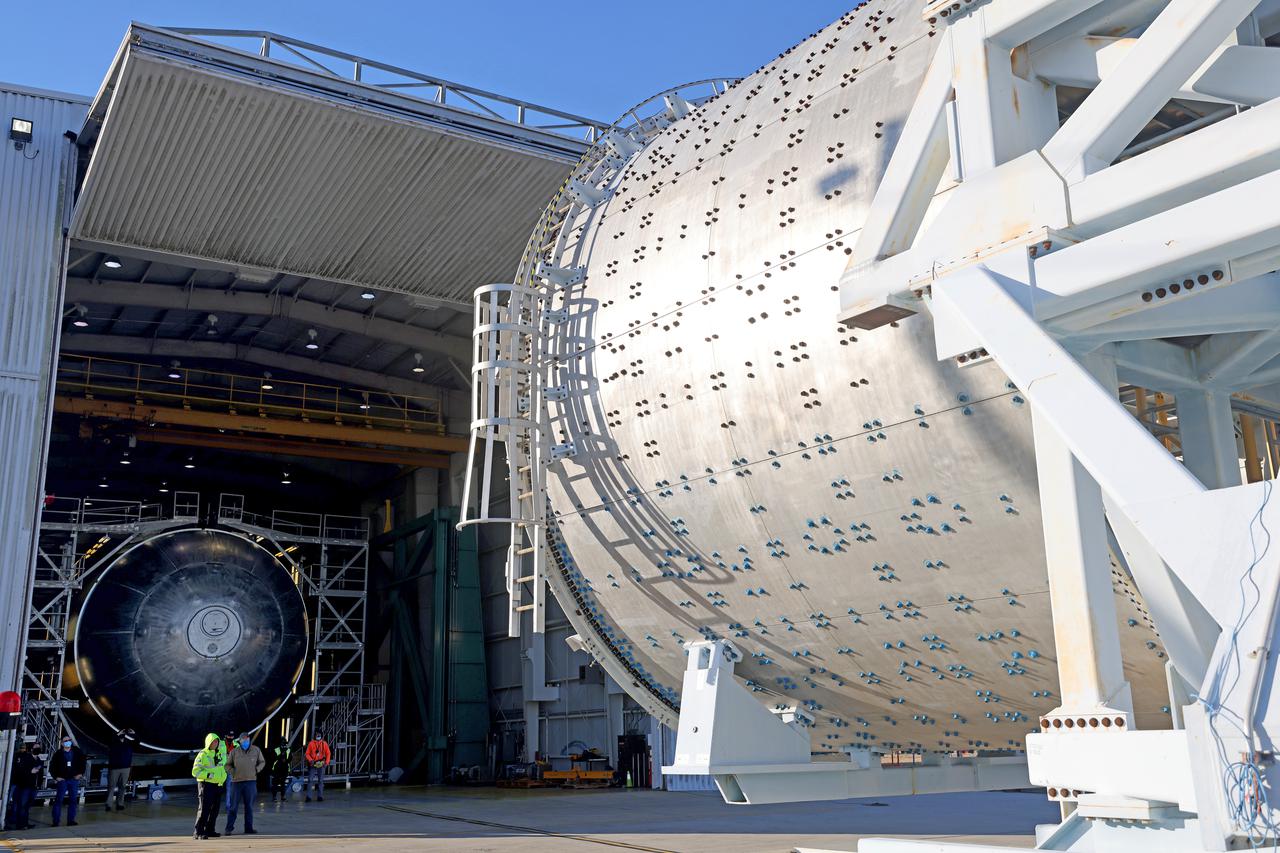
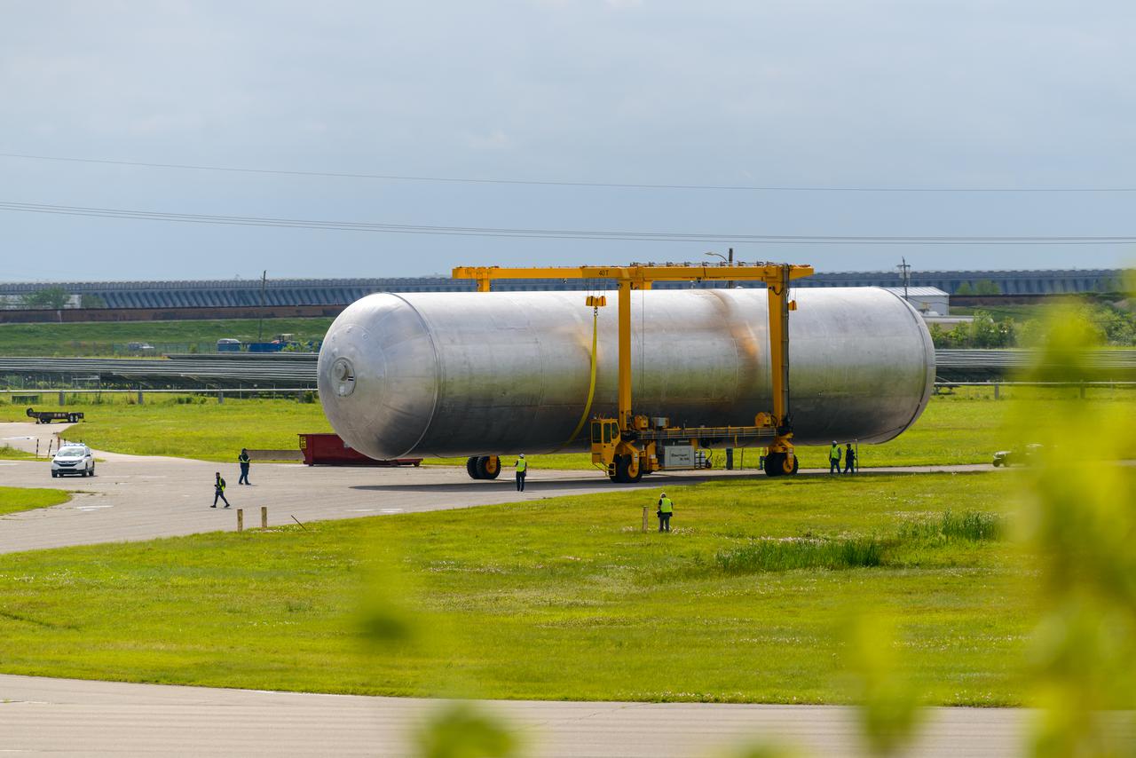
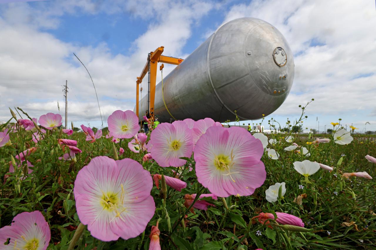
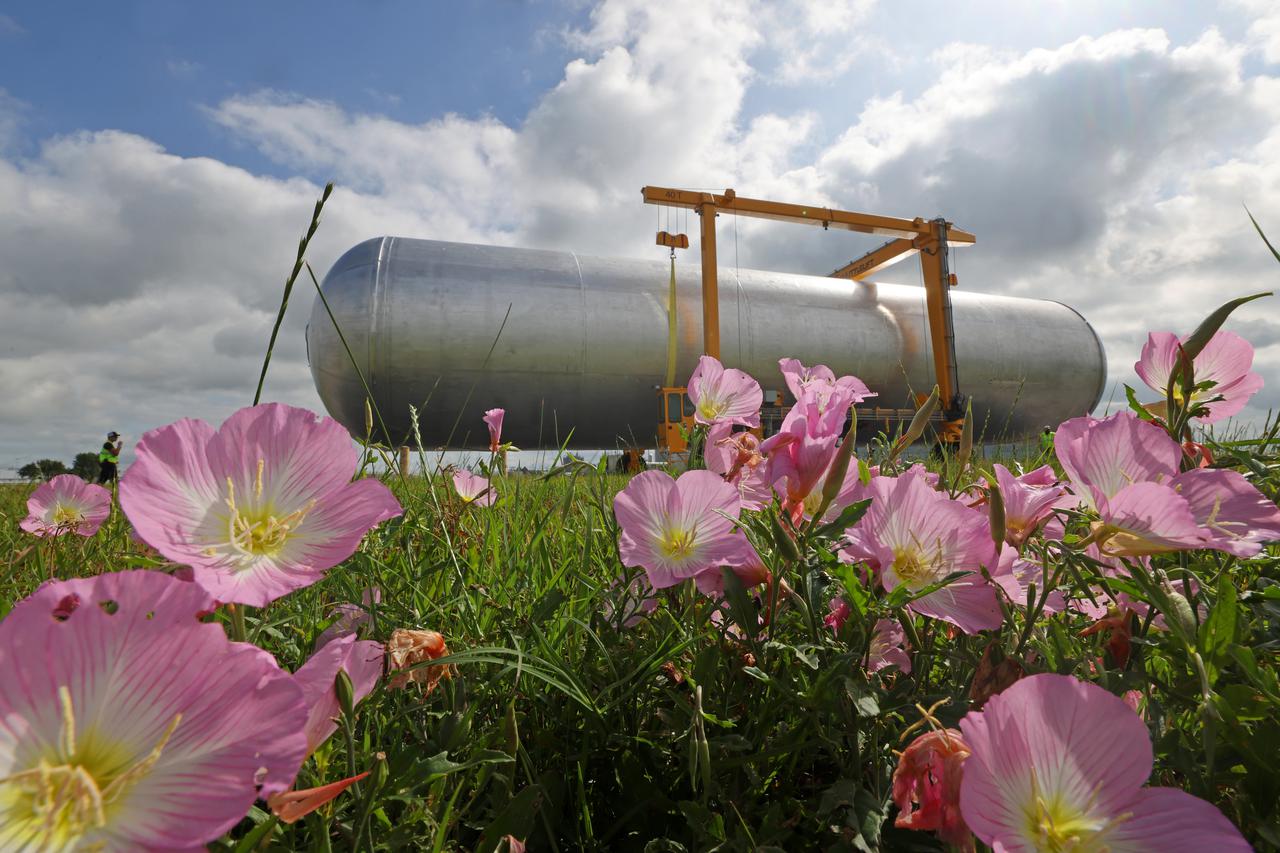
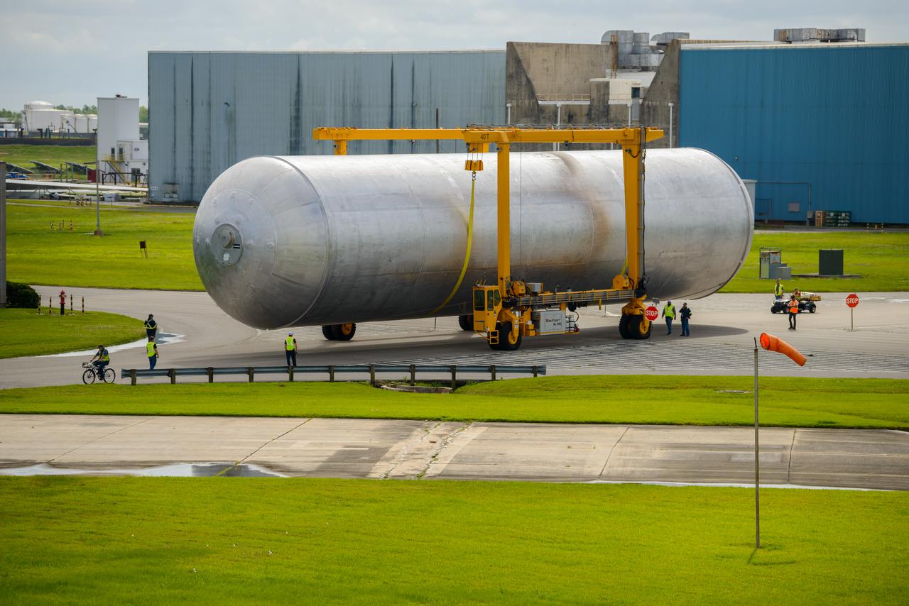
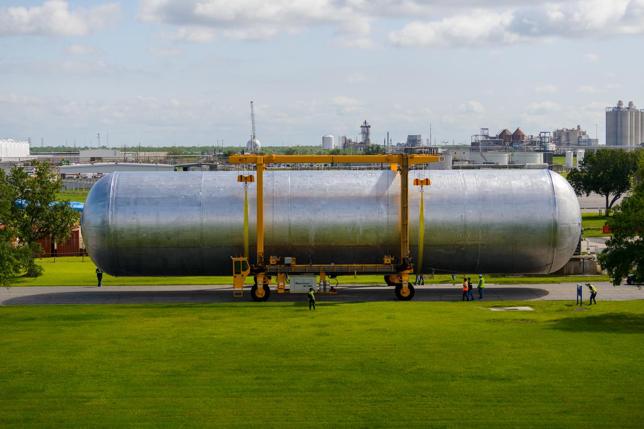
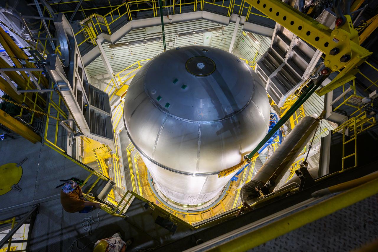
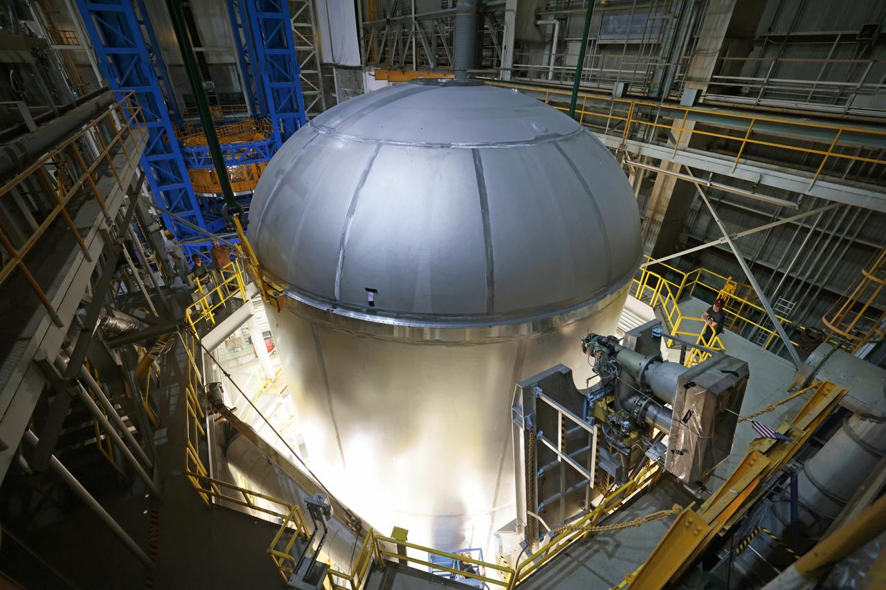
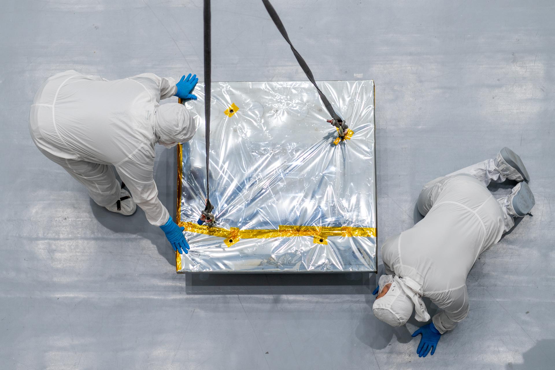
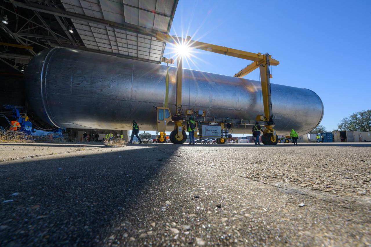
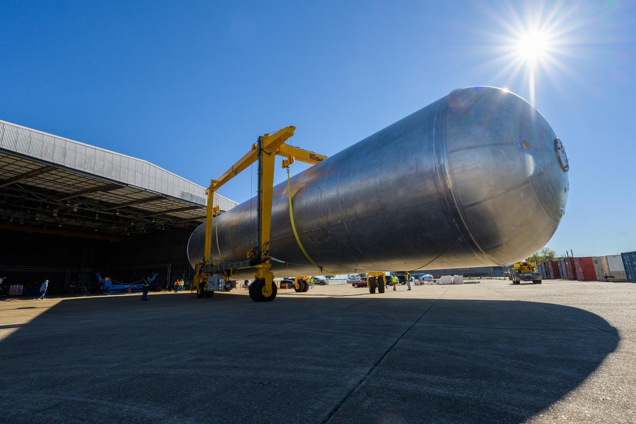
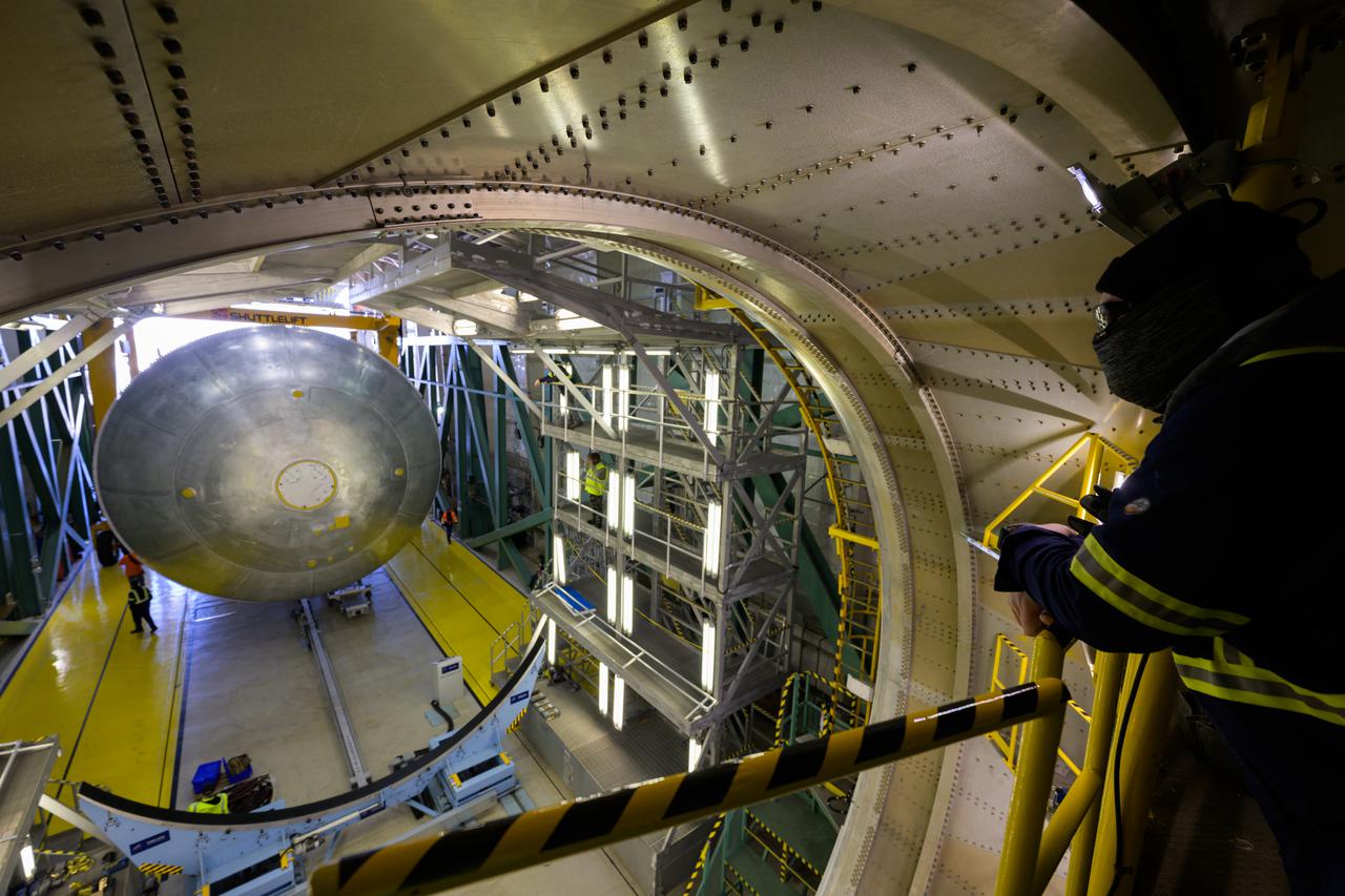
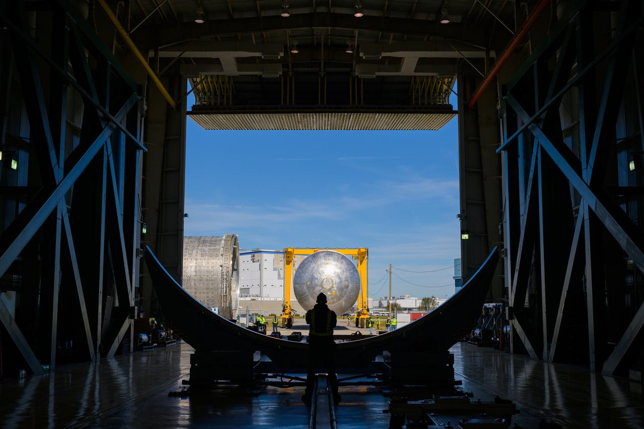
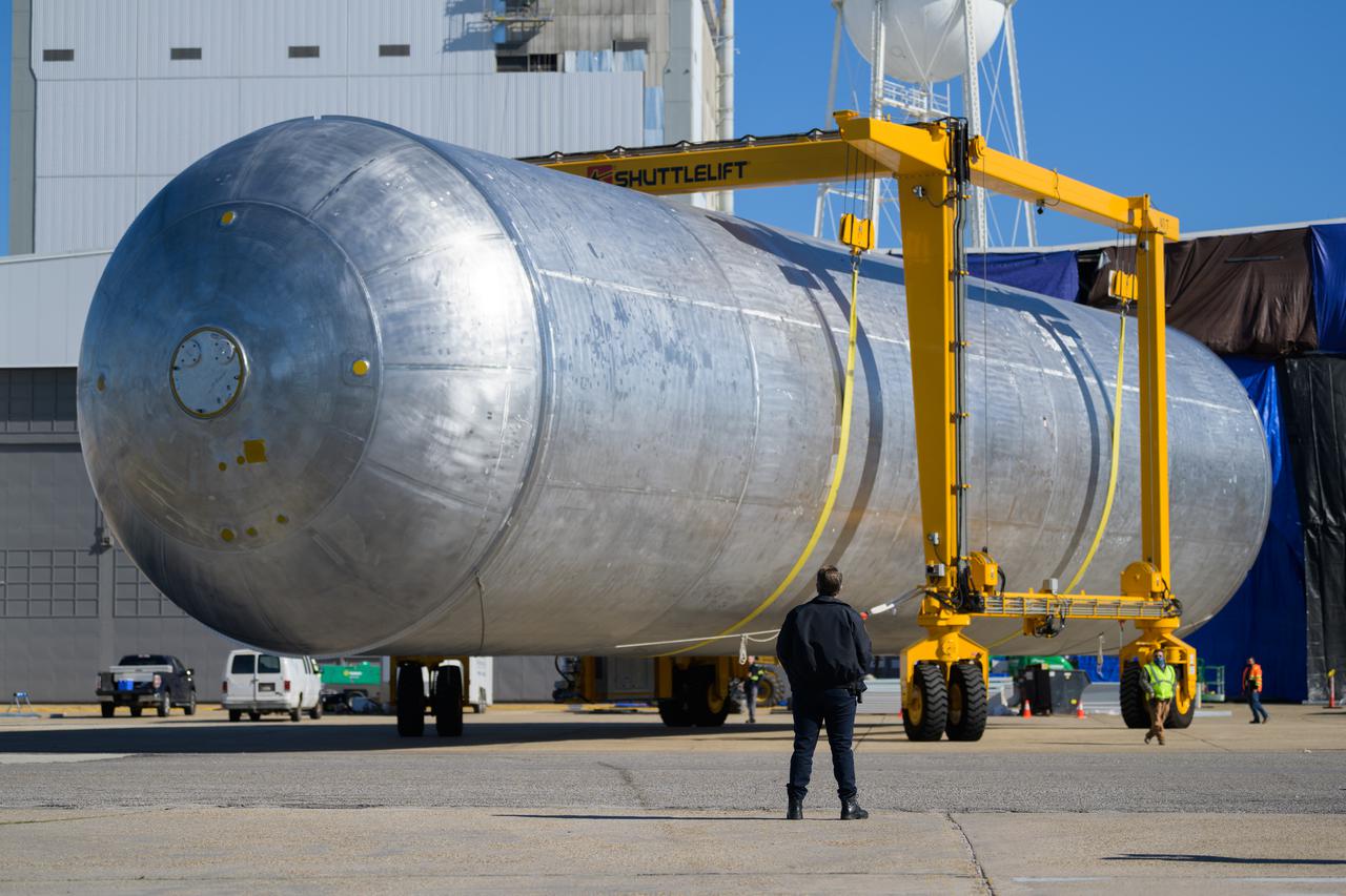
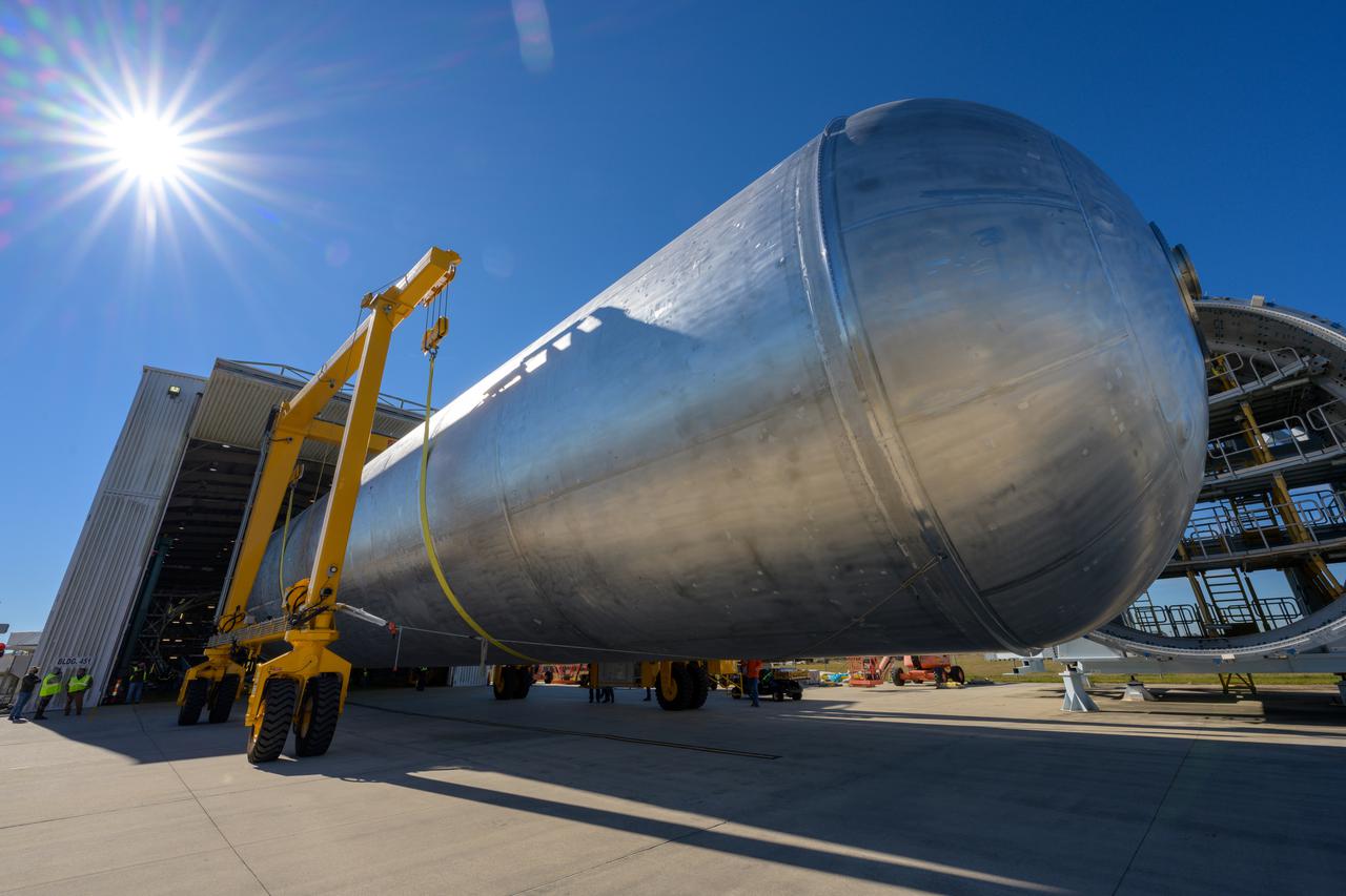
Teams at NASA’s Michoud Assembly Facility in New Orleans successfully completed hydrostatic proof testing of the core stage liquid oxygen tank for the agency’s Artemis III mission. The non-destructive evaluation method tests the structural integrity of the tank’s welds by filling the tank with water, simulating the propellant used during launch. The hardware was then moved to an adjacent cell for internal cleaning. Next, the tank will be readied for primer and application of its thermal protection system. The propellant tank is one of five major elements that make up the 212-foot-tall rocket stage. The core stage, along with its four RS-25 engines, produce two million pounds of thrust to help launch NASA’s Orion spacecraft, astronauts, and supplies beyond Earth’s orbit and to the lunar surface for Artemis.
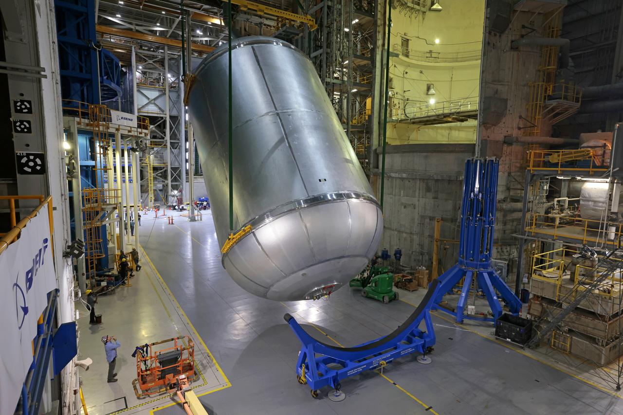
Teams at NASA’s Michoud Assembly Facility in New Orleans successfully completed hydrostatic proof testing of the core stage liquid oxygen tank for the agency’s Artemis III mission. The non-destructive evaluation method tests the structural integrity of the tank’s welds by filling the tank with water, simulating the propellant used during launch. The hardware was then moved to an adjacent cell for internal cleaning. Next, the tank will be readied for primer and application of its thermal protection system. The propellant tank is one of five major elements that make up the 212-foot-tall rocket stage. The core stage, along with its four RS-25 engines, produce two million pounds of thrust to help launch NASA’s Orion spacecraft, astronauts, and supplies beyond Earth’s orbit and to the lunar surface for Artemis. Image credit: NASA/Michael DeMocker
Teams at NASA’s Michoud Assembly Facility in New Orleans successfully completed hydrostatic proof testing of the core stage liquid oxygen tank for the agency’s Artemis III mission. The non-destructive evaluation method tests the structural integrity of the tank’s welds by filling the tank with water, simulating the propellant used during launch. The hardware was then moved to an adjacent cell for internal cleaning. Next, the tank will be readied for primer and application of its thermal protection system. The propellant tank is one of five major elements that make up the 212-foot-tall rocket stage. The core stage, along with its four RS-25 engines, produce two million pounds of thrust to help launch NASA’s Orion spacecraft, astronauts, and supplies beyond Earth’s orbit and to the lunar surface for Artemis.
Teams at NASA’s Michoud Assembly Facility in New Orleans successfully completed hydrostatic proof testing of the core stage liquid oxygen tank for the agency’s Artemis III mission. The non-destructive evaluation method tests the structural integrity of the tank’s welds by filling the tank with water, simulating the propellant used during launch. The hardware was then moved to an adjacent cell for internal cleaning. Next, the tank will be readied for primer and application of its thermal protection system. The propellant tank is one of five major elements that make up the 212-foot-tall rocket stage. The core stage, along with its four RS-25 engines, produce two million pounds of thrust to help launch NASA’s Orion spacecraft, astronauts, and supplies beyond Earth’s orbit and to the lunar surface for Artemis.
Teams at NASA’s Michoud Assembly Facility in New Orleans successfully completed hydrostatic proof testing of the core stage liquid oxygen tank for the agency’s Artemis III mission. The non-destructive evaluation method tests the structural integrity of the tank’s welds by filling the tank with water, simulating the propellant used during launch. The hardware was then moved to an adjacent cell for internal cleaning. Next, the tank will be readied for primer and application of its thermal protection system. The propellant tank is one of five major elements that make up the 212-foot-tall rocket stage. The core stage, along with its four RS-25 engines, produce two million pounds of thrust to help launch NASA’s Orion spacecraft, astronauts, and supplies beyond Earth’s orbit and to the lunar surface for Artemis. Image credit: NASA/Michael DeMocker
Teams at NASA’s Michoud Assembly Facility in New Orleans successfully completed hydrostatic proof testing of the core stage liquid oxygen tank for the agency’s Artemis III mission. The non-destructive evaluation method tests the structural integrity of the tank’s welds by filling the tank with water, simulating the propellant used during launch. The hardware was then moved to an adjacent cell for internal cleaning. Next, the tank will be readied for primer and application of its thermal protection system. The propellant tank is one of five major elements that make up the 212-foot-tall rocket stage. The core stage, along with its four RS-25 engines, produce two million pounds of thrust to help launch NASA’s Orion spacecraft, astronauts, and supplies beyond Earth’s orbit and to the lunar surface for Artemis. Image credit: NASA/Michael DeMocker
OSAM-1 team members prepare a weight to be crane lifted onto the SPIKA work platform as part of its commissioning workmanship test inside the cleanroom at Goddard Space Flight Center, Greenbelt Md., Mar 20, 2023. This photo has been reviewed by OSAM1 project management and the Export Control Office and is released for public view. NASA/Mike Guinto

CAPE CANAVERAL, Fla. – The Orion Exploration Flight Test 1 crew module is undergoing proof pressure testing at the Operations and Checkout Building at NASA's Kennedy Space Center in Florida. The test incrementally pressurizes the spacecraft with breathing air and is designed to demonstrate weld strength capability and structural performance at maximum flight operating pressures. Orion is the exploration spacecraft designed to carry crews to space beyond low Earth orbit. It will provide emergency abort capability, sustain the crew during the space travel and provide safe re-entry from deep space return velocities. The first unpiloted test flight of the Orion is scheduled to launch in 2014 atop a Delta IV rocket and in 2017 on a Space Launch System rocket. For more information, visit http://www.nasa.gov/orion Photo credit: NASA/Ben Smegelsky

CAPE CANAVERAL, Fla. – The Orion Exploration Flight Test 1 crew module is undergoing proof pressure testing at the Operations and Checkout Building at NASA's Kennedy Space Center in Florida. The test incrementally pressurizes the spacecraft with breathing air and is designed to demonstrate weld strength capability and structural performance at maximum flight operating pressures. Orion is the exploration spacecraft designed to carry crews to space beyond low Earth orbit. It will provide emergency abort capability, sustain the crew during the space travel and provide safe re-entry from deep space return velocities. The first unpiloted test flight of the Orion is scheduled to launch in 2014 atop a Delta IV rocket and in 2017 on a Space Launch System rocket. For more information, visit http://www.nasa.gov/orion Photo credit: NASA/Ben Smegelsky
CAPE CANAVERAL, Fla. – The Orion Exploration Flight Test 1 crew module is undergoing proof pressure testing at the Operations and Checkout Building at NASA's Kennedy Space Center in Florida. The test incrementally pressurizes the spacecraft with breathing air and is designed to demonstrate weld strength capability and structural performance at maximum flight operating pressures. Orion is the exploration spacecraft designed to carry crews to space beyond low Earth orbit. It will provide emergency abort capability, sustain the crew during the space travel and provide safe re-entry from deep space return velocities. The first unpiloted test flight of the Orion is scheduled to launch in 2014 atop a Delta IV rocket and in 2017 on a Space Launch System rocket. For more information, visit http://www.nasa.gov/orion Photo credit: NASA/Ben Smegelsky
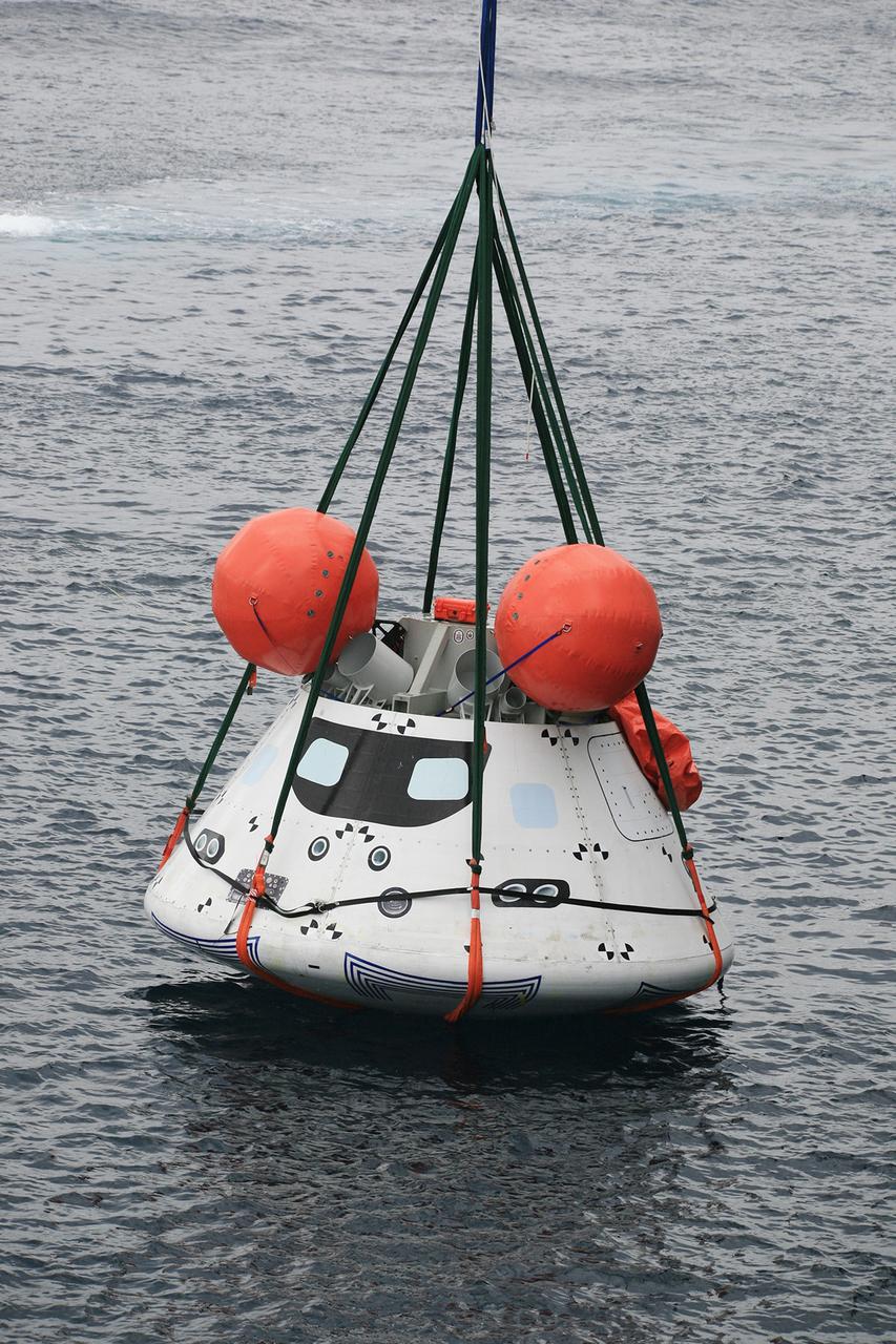
SAN DIEGO, Calif. – The Orion boilerplate test vehicle is slightly lifted by crane from the water to test the proof of concept basket lift method during an evolution of the Underway Recovery Test near the USS Anchorage in the Pacific Ocean off the coast of San Diego. NASA, Lockheed Martin and the U.S. Navy are conducting the test to prepare for recovery of the Orion crew module on its return from a deep space mission. The underway recovery test will allow the teams to demonstrate and evaluate the recovery processes, procedures, new hardware and personnel in open waters. The Ground Systems Development and Operations Program is conducting the underway recovery test. Orion is the exploration spacecraft designed to carry astronauts to destinations not yet explored by humans, including an asteroid and Mars. It will have emergency abort capability, sustain the crew during space travel and provide safe re-entry from deep space return velocities. The first unpiloted test flight of the Orion is scheduled to launch in 2014 atop a Delta IV rocket and in 2017 on NASA’s Space Launch System rocket. For more information, visit http://www.nasa.gov/orion. Photo credit: NASA/Kim Shiflett
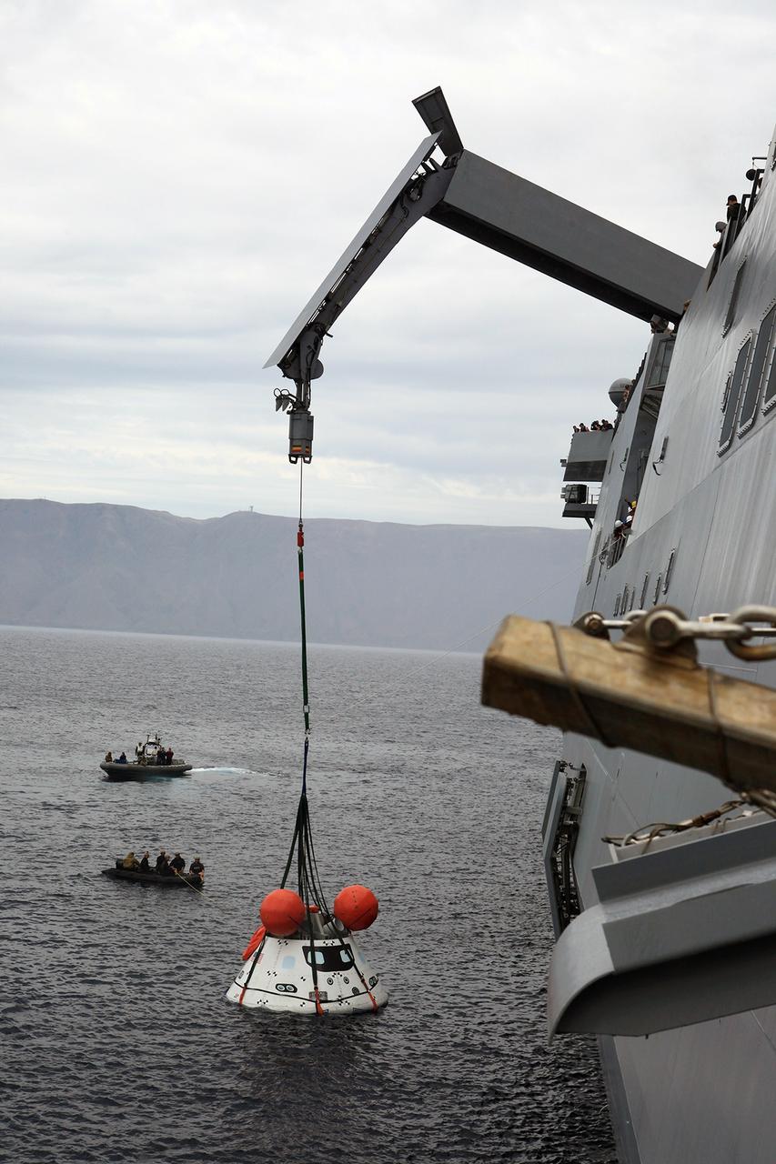
SAN DIEGO, Calif. – The Orion boilerplate test vehicle is slightly lifted by crane from the water to test the proof of concept basket lift method during an evolution of the Underway Recovery Test 2 near the USS Anchorage in the Pacific Ocean off the coast of San Diego. U.S. Navy personnel are nearby in two rigid hull inflatable boats. NASA, Lockheed Martin and the U.S. Navy are conducting the test to prepare for recovery of the Orion crew module on its return from a deep space mission. The underway recovery test will allow the teams to demonstrate and evaluate the recovery processes, procedures, new hardware and personnel in open waters. The Ground Systems Development and Operations Program is conducting the underway recovery test. Orion is the exploration spacecraft designed to carry astronauts to destinations not yet explored by humans, including an asteroid and Mars. It will have emergency abort capability, sustain the crew during space travel and provide safe re-entry from deep space return velocities. The first unpiloted test flight of the Orion is scheduled to launch in 2014 atop a Delta IV rocket and in 2017 on NASA’s Space Launch System rocket. For more information, visit http://www.nasa.gov/orion. Photo credit: NASA/Kim Shiflett

The Plankton, Aerosol, Cloud, ocean Ecosystem (PACE) spacecraft bus with mass mockups installed is lifted before structural proof testing at NASA's Goddard Space Flight Center in Greenbelt, Maryland on May 26th, 2021. PACE's unprecedented spectral coverage will provide the first-ever global measurements designed to identify phytoplankton community composition. The mission will make global ocean color measurements, using the Ocean Color Instrument (OCI), to provide extended data records on ocean ecology and global biogeochemistry along with polarimetry measurements, using the Spectro-polarimeter for Planetary Exploration (SPEXone) and the Hyper Angular Research Polarimeter (HARP2) to provide extended data records on clouds and aerosols. The Earth-observing satellite mission, built at Goddard Space Flight Center in Greenbelt, MD, will continue and advance observations of global ocean color, biogeochemistry, and ecology, as well as the carbon cycle, aerosols and clouds.
CAPE CANAVERAL, Fla. -- Inside the Operations and Checkout Building high bay at NASA’s Kennedy Space Center in Florida, a technician practices a procedure to repair cracks on the agency’s Orion Exploration Flight Test 1 crew module, during a dry run. During proof pressure testing on the vehicle, the spacecraft sustained three cracks in the aft bulkhead. A team composed of Lockheed Martin and NASA engineers designed a set of brackets that will be used to repair the area, as well as tooling to fix the cracked structure. Orion is the exploration spacecraft designed to carry humans further into space than ever before. It will provide emergency abort capability, sustain the crew during the space travel and provide safe re-entry from deep space return velocities. Orion’s first unpiloted test flight is scheduled to launch in 2014 atop a United Launch Alliance Delta IV heavy rocket. A second uncrewed flight test is scheduled for 2017 on the Space Launch System rocket. For more information, visit http:__www.nasa.gov_orion. Photo credit: NASA_Dimitri Gerondidakis
CAPE CANAVERAL, Fla. -- Inside the Operations and Checkout Building high bay at NASA’s Kennedy Space Center in Florida, a technician practices a procedure to repair cracks on the agency’s Orion Exploration Flight Test 1 crew module, during a dry run. During proof pressure testing on the vehicle, the spacecraft sustained three cracks in the aft bulkhead. A team composed of Lockheed Martin and NASA engineers designed a set of brackets that will be used to repair the area, as well as tooling to fix the cracked structure. Orion is the exploration spacecraft designed to carry humans further into space than ever before. It will provide emergency abort capability, sustain the crew during the space travel and provide safe re-entry from deep space return velocities. Orion’s first unpiloted test flight is scheduled to launch in 2014 atop a United Launch Alliance Delta IV heavy rocket. A second uncrewed flight test is scheduled for 2017 on the Space Launch System rocket. For more information, visit http:__www.nasa.gov_orion. Photo credit: NASA_Dimitri Gerondidakis
CAPE CANAVERAL, Fla. -- Inside the Operations and Checkout Building high bay at NASA’s Kennedy Space Center in Florida, a technician practices a procedure to repair cracks on the agency’s Orion Exploration Flight Test 1 crew module, during a dry run. During proof pressure testing on the vehicle, the spacecraft sustained three cracks in the aft bulkhead. A team composed of Lockheed Martin and NASA engineers designed a set of brackets that will be used to repair the area, as well as tooling to fix the cracked structure. Orion is the exploration spacecraft designed to carry humans further into space than ever before. It will provide emergency abort capability, sustain the crew during the space travel and provide safe re-entry from deep space return velocities. Orion’s first unpiloted test flight is scheduled to launch in 2014 atop a United Launch Alliance Delta IV heavy rocket. A second uncrewed flight test is scheduled for 2017 on the Space Launch System rocket. For more information, visit http:__www.nasa.gov_orion. Photo credit: NASA_Dimitri Gerondidakis
CAPE CANAVERAL, Fla. -- Inside the Operations and Checkout Building high bay at NASA’s Kennedy Space Center in Florida, a technician practices a procedure to repair cracks on the agency’s Orion Exploration Flight Test 1 crew module, during a dry run. During proof pressure testing on the vehicle, the spacecraft sustained three cracks in the aft bulkhead. A team composed of Lockheed Martin and NASA engineers designed a set of brackets that will be used to repair the area, as well as tooling to fix the cracked structure. Orion is the exploration spacecraft designed to carry humans further into space than ever before. It will provide emergency abort capability, sustain the crew during the space travel and provide safe re-entry from deep space return velocities. Orion’s first unpiloted test flight is scheduled to launch in 2014 atop a United Launch Alliance Delta IV heavy rocket. A second uncrewed flight test is scheduled for 2017 on the Space Launch System rocket. For more information, visit http:__www.nasa.gov_orion. Photo credit: NASA_Dimitri Gerondidakis
CAPE CANAVERAL, Fla. -- Inside the Operations and Checkout Building high bay at NASA’s Kennedy Space Center in Florida, a technician practices a procedure to repair cracks on the agency’s Orion Exploration Flight Test 1 crew module, during a dry run. During proof pressure testing on the vehicle, the spacecraft sustained three cracks in the aft bulkhead. A team composed of Lockheed Martin and NASA engineers designed a set of brackets that will be used to repair the area, as well as tooling to fix the cracked structure. Orion is the exploration spacecraft designed to carry humans further into space than ever before. It will provide emergency abort capability, sustain the crew during the space travel and provide safe re-entry from deep space return velocities. Orion’s first unpiloted test flight is scheduled to launch in 2014 atop a United Launch Alliance Delta IV heavy rocket. A second uncrewed flight test is scheduled for 2017 on the Space Launch System rocket. For more information, visit http:__www.nasa.gov_orion. Photo credit: NASA_Dimitri Gerondidakis
The liquid hydrogen tank that will be part of the Space Launch System rocket’s core stage is being prepared for the Artemis III mission at NASA’s Michoud Assembly Facility in New Orleans. Eventually, the tank will be connected to the engine section that will house the four RS-25 engines. Once the aft simulator is attached, the LH2 tank undergoes non-destructive evaluation, which will test weld strength and ensure the tank is structurally sound. The SLS core stage is made up of five unique elements: the forward skirt, liquid oxygen tank, intertank, liquid hydrogen tank, and the engine section. The tank holds 537,000 gallons of liquid hydrogen cooled to minus 432 degrees Fahrenheit and sits between the core stage’s intertank and engine section. The liquid hydrogen hardware, along with the liquid oxygen tank, will provide propellant to the four RS-25 engines at the bottom of the core stage to produce more than two million pounds of thrust to help launch the Artemis III mission to the Moon. Together with its four RS-25 engines, the rocket’s massive 212-foot-tall core stage — the largest stage NASA has ever built — and its twin solid rocket boosters will produce 8.8 million pounds of thrust to send NASA’s Orion spacecraft, astronauts and supplies beyond Earth’s orbit to the Moon.
The liquid hydrogen tank that will be part of the Space Launch System rocket’s core stage is being prepared for the Artemis III mission at NASA’s Michoud Assembly Facility in New Orleans. Eventually, the tank will be connected to the engine section that will house the four RS-25 engines. Once the aft simulator is attached, the LH2 tank undergoes non-destructive evaluation, which will test weld strength and ensure the tank is structurally sound. The SLS core stage is made up of five unique elements: the forward skirt, liquid oxygen tank, intertank, liquid hydrogen tank, and the engine section. The tank holds 537,000 gallons of liquid hydrogen cooled to minus 432 degrees Fahrenheit and sits between the core stage’s intertank and engine section. The liquid hydrogen hardware, along with the liquid oxygen tank, will provide propellant to the four RS-25 engines at the bottom of the core stage to produce more than two million pounds of thrust to help launch the Artemis III mission to the Moon. Together with its four RS-25 engines, the rocket’s massive 212-foot-tall core stage — the largest stage NASA has ever built — and its twin solid rocket boosters will produce 8.8 million pounds of thrust to send NASA’s Orion spacecraft, astronauts and supplies beyond Earth’s orbit to the Moon.
The liquid hydrogen tank that will be part of the Space Launch System rocket’s core stage is being prepared for the Artemis III mission at NASA’s Michoud Assembly Facility in New Orleans. Eventually, the tank will be connected to the engine section that will house the four RS-25 engines. Once the aft simulator is attached, the LH2 tank undergoes non-destructive evaluation, which will test weld strength and ensure the tank is structurally sound. The SLS core stage is made up of five unique elements: the forward skirt, liquid oxygen tank, intertank, liquid hydrogen tank, and the engine section. The tank holds 537,000 gallons of liquid hydrogen cooled to minus 432 degrees Fahrenheit and sits between the core stage’s intertank and engine section. The liquid hydrogen hardware, along with the liquid oxygen tank, will provide propellant to the four RS-25 engines at the bottom of the core stage to produce more than two million pounds of thrust to help launch the Artemis III mission to the Moon. Together with its four RS-25 engines, the rocket’s massive 212-foot-tall core stage — the largest stage NASA has ever built — and its twin solid rocket boosters will produce 8.8 million pounds of thrust to send NASA’s Orion spacecraft, astronauts and supplies beyond Earth’s orbit to the Moon.
The liquid hydrogen tank that will be part of the Space Launch System rocket’s core stage is being prepared for the Artemis III mission at NASA’s Michoud Assembly Facility in New Orleans. Eventually, the tank will be connected to the engine section that will house the four RS-25 engines. Once the aft simulator is attached, the LH2 tank undergoes non-destructive evaluation, which will test weld strength and ensure the tank is structurally sound. The SLS core stage is made up of five unique elements: the forward skirt, liquid oxygen tank, intertank, liquid hydrogen tank, and the engine section. The tank holds 537,000 gallons of liquid hydrogen cooled to minus 432 degrees Fahrenheit and sits between the core stage’s intertank and engine section. The liquid hydrogen hardware, along with the liquid oxygen tank, will provide propellant to the four RS-25 engines at the bottom of the core stage to produce more than two million pounds of thrust to help launch the Artemis III mission to the Moon. Together with its four RS-25 engines, the rocket’s massive 212-foot-tall core stage — the largest stage NASA has ever built — and its twin solid rocket boosters will produce 8.8 million pounds of thrust to send NASA’s Orion spacecraft, astronauts and supplies beyond Earth’s orbit to the Moon.
The liquid hydrogen tank that will be part of the Space Launch System rocket’s core stage is being prepared for the Artemis III mission at NASA’s Michoud Assembly Facility in New Orleans. Eventually, the tank will be connected to the engine section that will house the four RS-25 engines. Once the aft simulator is attached, the LH2 tank undergoes non-destructive evaluation, which will test weld strength and ensure the tank is structurally sound. The SLS core stage is made up of five unique elements: the forward skirt, liquid oxygen tank, intertank, liquid hydrogen tank, and the engine section. The tank holds 537,000 gallons of liquid hydrogen cooled to minus 432 degrees Fahrenheit and sits between the core stage’s intertank and engine section. The liquid hydrogen hardware, along with the liquid oxygen tank, will provide propellant to the four RS-25 engines at the bottom of the core stage to produce more than two million pounds of thrust to help launch the Artemis III mission to the Moon. Together with its four RS-25 engines, the rocket’s massive 212-foot-tall core stage — the largest stage NASA has ever built — and its twin solid rocket boosters will produce 8.8 million pounds of thrust to send NASA’s Orion spacecraft, astronauts and supplies beyond Earth’s orbit to the Moon.
The liquid hydrogen tank that will be part of the Space Launch System rocket’s core stage is being prepared for the Artemis III mission at NASA’s Michoud Assembly Facility in New Orleans. Eventually, the tank will be connected to the engine section that will house the four RS-25 engines. Once the aft simulator is attached, the LH2 tank undergoes non-destructive evaluation, which will test weld strength and ensure the tank is structurally sound. The SLS core stage is made up of five unique elements: the forward skirt, liquid oxygen tank, intertank, liquid hydrogen tank, and the engine section. The tank holds 537,000 gallons of liquid hydrogen cooled to minus 432 degrees Fahrenheit and sits between the core stage’s intertank and engine section. The liquid hydrogen hardware, along with the liquid oxygen tank, will provide propellant to the four RS-25 engines at the bottom of the core stage to produce more than two million pounds of thrust to help launch the Artemis III mission to the Moon. Together with its four RS-25 engines, the rocket’s massive 212-foot-tall core stage — the largest stage NASA has ever built — and its twin solid rocket boosters will produce 8.8 million pounds of thrust to send NASA’s Orion spacecraft, astronauts and supplies beyond Earth’s orbit to the Moon.
The liquid hydrogen tank that will be part of the Space Launch System rocket’s core stage is being prepared for the Artemis III mission at NASA’s Michoud Assembly Facility in New Orleans. Eventually, the tank will be connected to the engine section that will house the four RS-25 engines. Once the aft simulator is attached, the LH2 tank undergoes non-destructive evaluation, which will test weld strength and ensure the tank is structurally sound. The SLS core stage is made up of five unique elements: the forward skirt, liquid oxygen tank, intertank, liquid hydrogen tank, and the engine section. The tank holds 537,000 gallons of liquid hydrogen cooled to minus 432 degrees Fahrenheit and sits between the core stage’s intertank and engine section. The liquid hydrogen hardware, along with the liquid oxygen tank, will provide propellant to the four RS-25 engines at the bottom of the core stage to produce more than two million pounds of thrust to help launch the Artemis III mission to the Moon. Together with its four RS-25 engines, the rocket’s massive 212-foot-tall core stage — the largest stage NASA has ever built — and its twin solid rocket boosters will produce 8.8 million pounds of thrust to send NASA’s Orion spacecraft, astronauts and supplies beyond Earth’s orbit to the Moon.
The liquid hydrogen tank that will be part of the Space Launch System rocket’s core stage is being prepared for the Artemis III mission at NASA’s Michoud Assembly Facility in New Orleans. Eventually, the tank will be connected to the engine section that will house the four RS-25 engines. Once the aft simulator is attached, the LH2 tank undergoes non-destructive evaluation, which will test weld strength and ensure the tank is structurally sound. The SLS core stage is made up of five unique elements: the forward skirt, liquid oxygen tank, intertank, liquid hydrogen tank, and the engine section. The tank holds 537,000 gallons of liquid hydrogen cooled to minus 432 degrees Fahrenheit and sits between the core stage’s intertank and engine section. The liquid hydrogen hardware, along with the liquid oxygen tank, will provide propellant to the four RS-25 engines at the bottom of the core stage to produce more than two million pounds of thrust to help launch the Artemis III mission to the Moon. Together with its four RS-25 engines, the rocket’s massive 212-foot-tall core stage — the largest stage NASA has ever built — and its twin solid rocket boosters will produce 8.8 million pounds of thrust to send NASA’s Orion spacecraft, astronauts and supplies beyond Earth’s orbit to the Moon.
The liquid hydrogen tank that will be part of the Space Launch System rocket’s core stage is being prepared for the Artemis III mission at NASA’s Michoud Assembly Facility in New Orleans. Eventually, the tank will be connected to the engine section that will house the four RS-25 engines. Once the aft simulator is attached, the LH2 tank undergoes non-destructive evaluation, which will test weld strength and ensure the tank is structurally sound. The SLS core stage is made up of five unique elements: the forward skirt, liquid oxygen tank, intertank, liquid hydrogen tank, and the engine section. The tank holds 537,000 gallons of liquid hydrogen cooled to minus 432 degrees Fahrenheit and sits between the core stage’s intertank and engine section. The liquid hydrogen hardware, along with the liquid oxygen tank, will provide propellant to the four RS-25 engines at the bottom of the core stage to produce more than two million pounds of thrust to help launch the Artemis III mission to the Moon. Together with its four RS-25 engines, the rocket’s massive 212-foot-tall core stage — the largest stage NASA has ever built — and its twin solid rocket boosters will produce 8.8 million pounds of thrust to send NASA’s Orion spacecraft, astronauts and supplies beyond Earth’s orbit to the Moon.

The liquid hydrogen tank that will be part of the Space Launch System rocket’s core stage is being prepared for the Artemis III mission at NASA’s Michoud Assembly Facility in New Orleans. Eventually, the tank will be connected to the engine section that will house the four RS-25 engines. Once the aft simulator is attached, the LH2 tank undergoes non-destructive evaluation, which will test weld strength and ensure the tank is structurally sound. The SLS core stage is made up of five unique elements: the forward skirt, liquid oxygen tank, intertank, liquid hydrogen tank, and the engine section. The tank holds 537,000 gallons of liquid hydrogen cooled to minus 432 degrees Fahrenheit and sits between the core stage’s intertank and engine section. The liquid hydrogen hardware, along with the liquid oxygen tank, will provide propellant to the four RS-25 engines at the bottom of the core stage to produce more than two million pounds of thrust to help launch the Artemis III mission to the Moon. Together with its four RS-25 engines, the rocket’s massive 212-foot-tall core stage — the largest stage NASA has ever built — and its twin solid rocket boosters will produce 8.8 million pounds of thrust to send NASA’s Orion spacecraft, astronauts and supplies beyond Earth’s orbit to the Moon.
The liquid hydrogen tank that will be part of the Space Launch System rocket’s core stage is being prepared for the Artemis III mission at NASA’s Michoud Assembly Facility in New Orleans. Eventually, the tank will be connected to the engine section that will house the four RS-25 engines. Once the aft simulator is attached, the LH2 tank undergoes non-destructive evaluation, which will test weld strength and ensure the tank is structurally sound. The SLS core stage is made up of five unique elements: the forward skirt, liquid oxygen tank, intertank, liquid hydrogen tank, and the engine section. The tank holds 537,000 gallons of liquid hydrogen cooled to minus 432 degrees Fahrenheit and sits between the core stage’s intertank and engine section. The liquid hydrogen hardware, along with the liquid oxygen tank, will provide propellant to the four RS-25 engines at the bottom of the core stage to produce more than two million pounds of thrust to help launch the Artemis III mission to the Moon. Together with its four RS-25 engines, the rocket’s massive 212-foot-tall core stage — the largest stage NASA has ever built — and its twin solid rocket boosters will produce 8.8 million pounds of thrust to send NASA’s Orion spacecraft, astronauts and supplies beyond Earth’s orbit to the Moon.
The liquid hydrogen tank that will be part of the Space Launch System rocket’s core stage is being prepared for the Artemis III mission at NASA’s Michoud Assembly Facility in New Orleans. Eventually, the tank will be connected to the engine section that will house the four RS-25 engines. Once the aft simulator is attached, the LH2 tank undergoes non-destructive evaluation, which will test weld strength and ensure the tank is structurally sound. The SLS core stage is made up of five unique elements: the forward skirt, liquid oxygen tank, intertank, liquid hydrogen tank, and the engine section. The tank holds 537,000 gallons of liquid hydrogen cooled to minus 432 degrees Fahrenheit and sits between the core stage’s intertank and engine section. The liquid hydrogen hardware, along with the liquid oxygen tank, will provide propellant to the four RS-25 engines at the bottom of the core stage to produce more than two million pounds of thrust to help launch the Artemis III mission to the Moon. Together with its four RS-25 engines, the rocket’s massive 212-foot-tall core stage — the largest stage NASA has ever built — and its twin solid rocket boosters will produce 8.8 million pounds of thrust to send NASA’s Orion spacecraft, astronauts and supplies beyond Earth’s orbit to the Moon.
The liquid hydrogen tank that will be part of the Space Launch System rocket’s core stage is being prepared for the Artemis III mission at NASA’s Michoud Assembly Facility in New Orleans. Eventually, the tank will be connected to the engine section that will house the four RS-25 engines. Once the aft simulator is attached, the LH2 tank undergoes non-destructive evaluation, which will test weld strength and ensure the tank is structurally sound. The SLS core stage is made up of five unique elements: the forward skirt, liquid oxygen tank, intertank, liquid hydrogen tank, and the engine section. The tank holds 537,000 gallons of liquid hydrogen cooled to minus 432 degrees Fahrenheit and sits between the core stage’s intertank and engine section. The liquid hydrogen hardware, along with the liquid oxygen tank, will provide propellant to the four RS-25 engines at the bottom of the core stage to produce more than two million pounds of thrust to help launch the Artemis III mission to the Moon. Together with its four RS-25 engines, the rocket’s massive 212-foot-tall core stage — the largest stage NASA has ever built — and its twin solid rocket boosters will produce 8.8 million pounds of thrust to send NASA’s Orion spacecraft, astronauts and supplies beyond Earth’s orbit to the Moon.

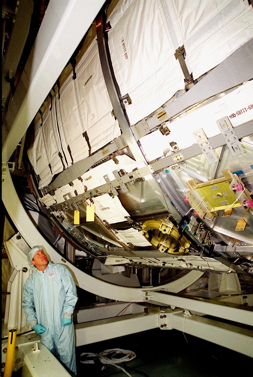
KENNEDY SPACE CENTER, FLA. -- In the Space Station Processing Facility, STS-98 Mission Specialist Thomas D. Jones (Ph.D.) looks up at the U.S. Lab Destiny with its debris shield blanket made of a material similar to that used in bullet-proof vests on Earth. Along with Commander Kenneth D. Cockrell and Pilot Mark Polansky, Jones is taking part in a Multi-Equipment Interface Test (MEIT) on this significant element of the International Space Station. During the STS-98 mission, the crew will install the Lab on the Station during a series of three spacewalks. The mission will provide the Station with science research facilities and expand its power, life support and control capabilities. The U.S. Laboratory Module continues a long tradition of microgravity materials research, first conducted by Skylab and later Shuttle and Spacelab missions. Destiny is expected to be a major feature in future research, providing facilities for biotechnology, fluid physics, combustion and life sciences reseach. The Lab is planned for launch aboard Space Shuttle Atlantis on the sixth ISS flight, currently targeted no earlier than August 19, 2000.
KENNEDY SPACE CENTER, FLA. -- In the Space Station Processing Facility, STS-98 Mission Specialist Thomas D. Jones (Ph.D.) looks up at the U.S. Lab Destiny with its debris shield blanket made of a material similar to that used in bullet-proof vests on Earth. Along with Commander Kenneth D. Cockrell and Pilot Mark Polansky, Jones is taking part in a Multi-Equipment Interface Test (MEIT) on this significant element of the International Space Station. During the STS-98 mission, the crew will install the Lab on the Station during a series of three spacewalks. The mission will provide the Station with science research facilities and expand its power, life support and control capabilities. The U.S. Laboratory Module continues a long tradition of microgravity materials research, first conducted by Skylab and later Shuttle and Spacelab missions. Destiny is expected to be a major feature in future research, providing facilities for biotechnology, fluid physics, combustion and life sciences reseach. The Lab is planned for launch aboard Space Shuttle Atlantis on the sixth ISS flight, currently targeted no earlier than August 19, 2000.
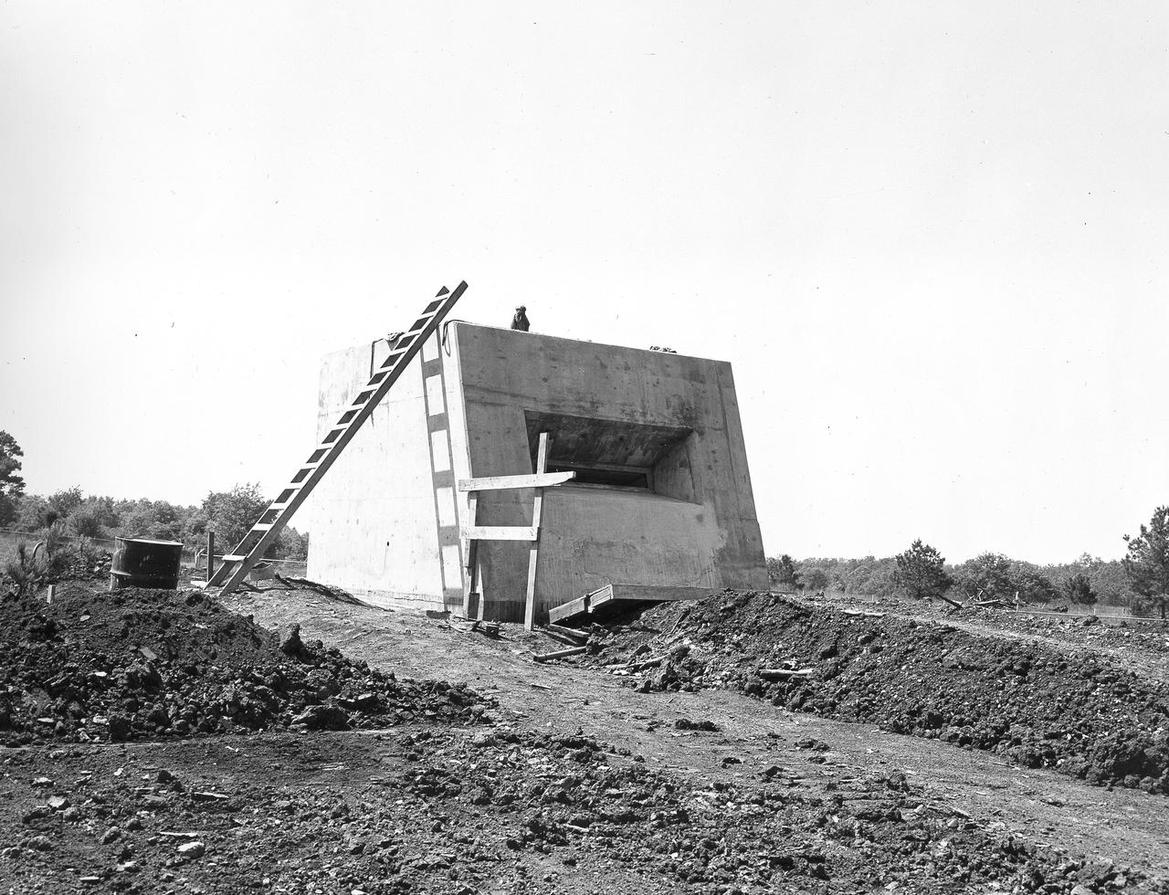
At its founding, the Marshall Space Flight Center (MSFC) inherited the Army’s Jupiter and Redstone test stands, but much larger facilities were needed for the giant stages of the Saturn V. From 1960 to 1964, the existing stands were remodeled and a sizable new test area was developed. The new comprehensive test complex for propulsion and structural dynamics was unique within the nation and the free world, and they remain so today because they were constructed with foresight to meet the future as well as on going needs. Construction of the S-IC Static test stand complex began in 1961 in the west test area of MSFC, and was completed in 1964. The S-IC static test stand was designed to develop and test the 138-ft long and 33-ft diameter Saturn V S-IC first stage, or booster stage, weighing in at 280,000 pounds. Required to hold down the brute force of a 7,500,000-pound thrust produced by 5 F-1 engines, the S-IC static test stand was designed and constructed with the strength of hundreds of tons of steel and 12,000,000 pounds of cement, planted down to bedrock 40 feet below ground level. The foundation walls, constructed with concrete and steel, are 4 feet thick. The base structure consists of four towers with 40-foot-thick walls extending upward 144 feet above ground level. The structure was topped by a crane with a 135-foot boom. With the boom in the upright position, the stand was given an overall height of 405 feet, placing it among the highest structures in Alabama at the time. In addition to the S-IC stand, additional related facilities were built during this time frame. Built to the east of the S-IC stand, the block house served as the control room. To the south of the blockhouse was a newly constructed pump house used for delivering water to the S-IC stand during testing. North of the massive test stand, the F-1 Engine test stand was built for testing a single F-1 engine. Just southeast of the S-IC stand a concrete bunker house was constructed. The bunker housed an emergency crew clad in fire proof gear, who were close at hand should any emergencies arise during testing. This photo of the completed bunker house was taken on May 7, 1963.

The XV-15 tilt rotor ships #1 and #2 parked on the NASA Dryden Flight Research Center ramp. The XV-15s, manufactured by Bell, were involved in limited research at Dryden in 1980 and 1981. The development of the XV-15 Tiltrotor research aircraft was initiated in 1973 with joint Army/NASA funding as a "proof of concept", or "technology demonstrator" program, with two aircraft being built by Bell Helicopter Textron (BHT) in 1977. The aircraft are powered by twin Lycoming T-53 turboshaft engines that are connected by a cross-shaft and drive three-bladed, 25 ft diameter metal rotors (the size extensively tested in a wind tunnel). The engines and main transmissions are located in wingtip nacelles to minimize the operational loads on the cross-shaft system and, with the rotors, tilt as a single unit. For takeoff, the proprotors and their engines are used in the straight-up position where the thrust is directed downward. The XV-15 then climbs vertically into the air like a helicopter. In this VTOL mode, the vehicle can lift off and hover for approximately one hour. Once off the ground, the XV-15 has the ability to fly in one of two different modes. It can fly as a helicopter, in the partially converted airplane mode. The XV-15 can also then convert from the helicopter mode to the airplane mode. This is accomplished by continuous rotation of the proprotors from the helicopter rotor position to the conventional airplane propeller position. During the ten to fifteen second conversion period, the aircraft speed increases and lift is transferred from the rotors to the wing. To land, the proprotors are rotated up to the helicopter rotor position and flown as a helicopter to a vertical landing.