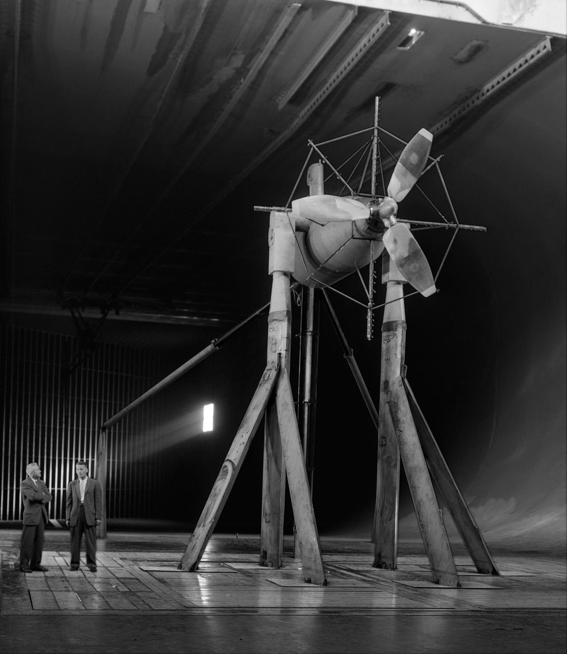
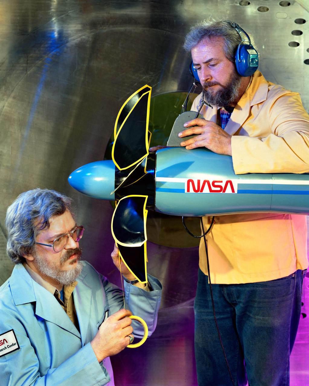
Investigation of cambered propeller design for VTOL/STOL airplane. 3/4 front view of Curtis VTOL propeller.
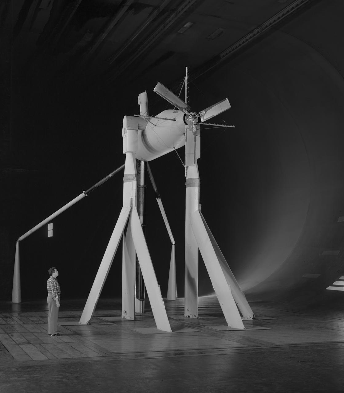
Investigation of cambered propeller design for VTOL/STOL airplane. 3/4 front view of complete configuration, 0 deg.
Propeller Swarm
Propeller Belt
Four Propellers
Propeller Close Up
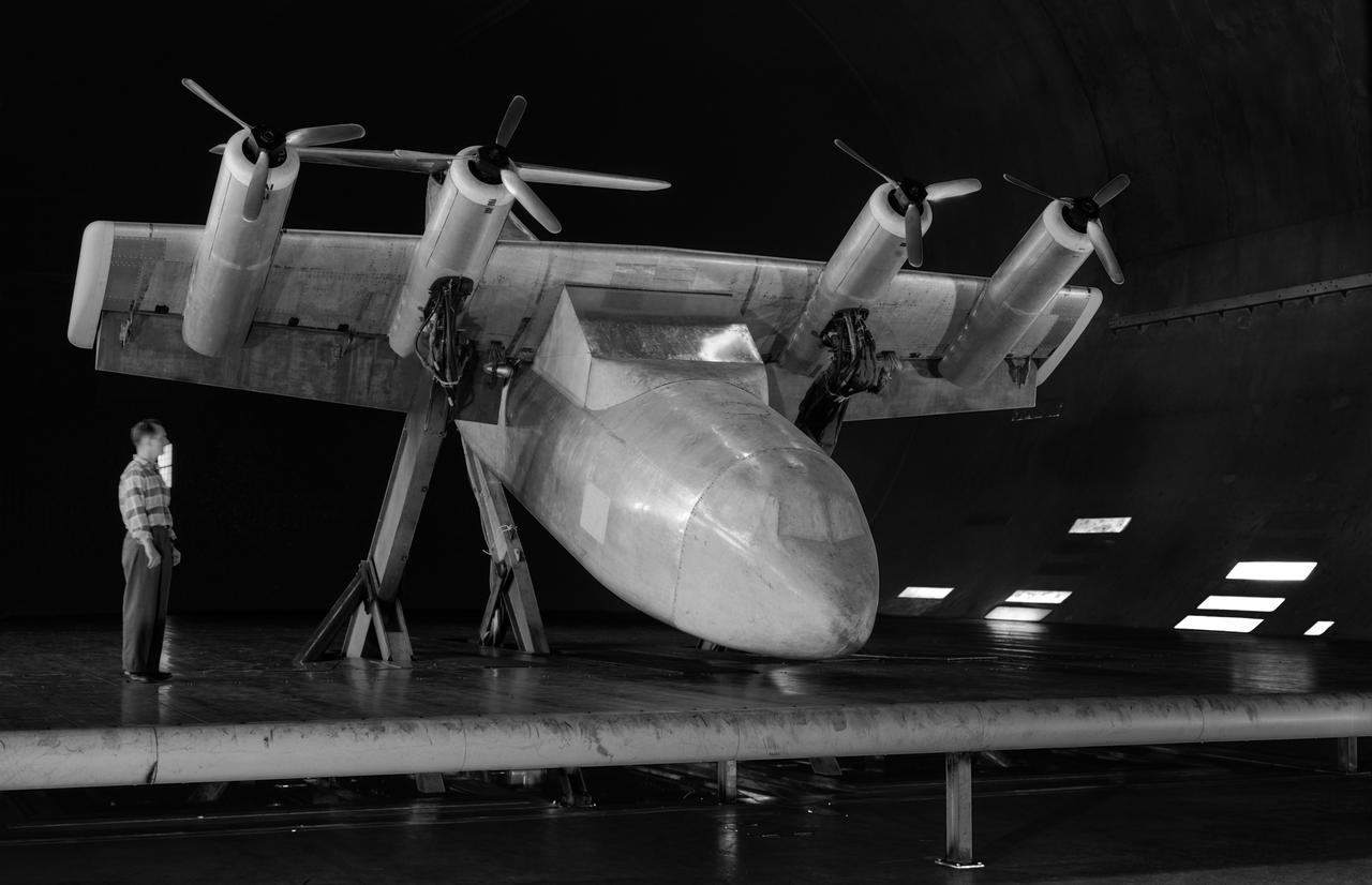
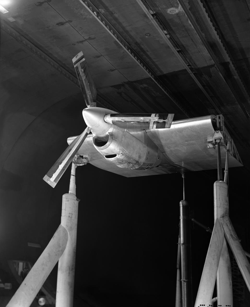
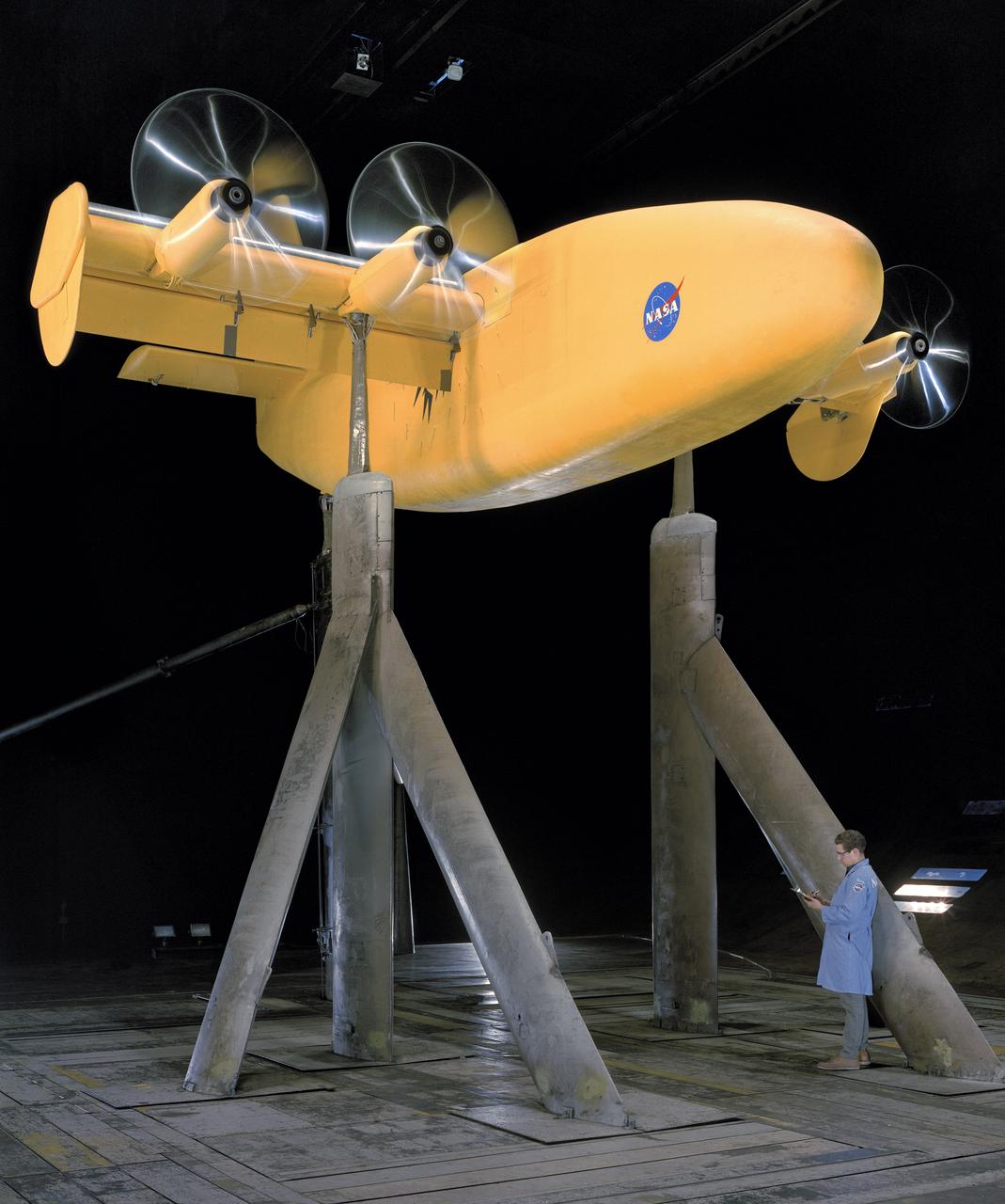
Tilt wing propeller model. 3/4 front view. 4 prop tilt wing nose down variable struts on ground board. Leo Holl, NASA Ames Engineer.

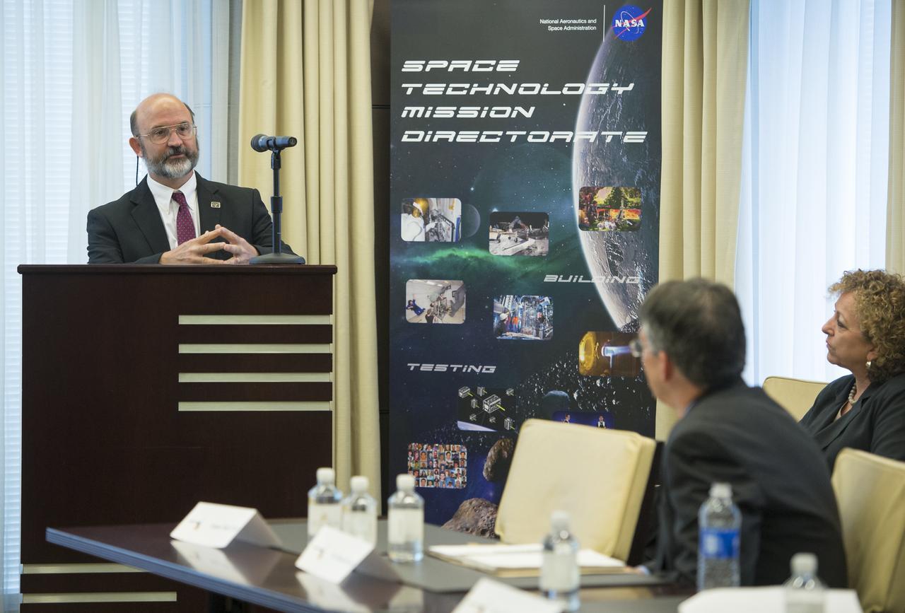
Dr. Michael Gazarik, Associate Administrator, NASA Space Technology Mission Directorate, answers a reporter's question at a Green Propellant Infusion Mission press conference at the Reserve Officers Association, Tuesday, July 9, 2013 in Washington. The NASA GPIM program, led by Ball Aerospace in conjunction with Aerojet Rocketdyne, is demonstrating a high-performance "green" fuel in space. The propellant used on this mission offers nearly 50 percent better performance when compared to traditional hydrazine. Photo Credit: (NASA/Carla Cioffi)
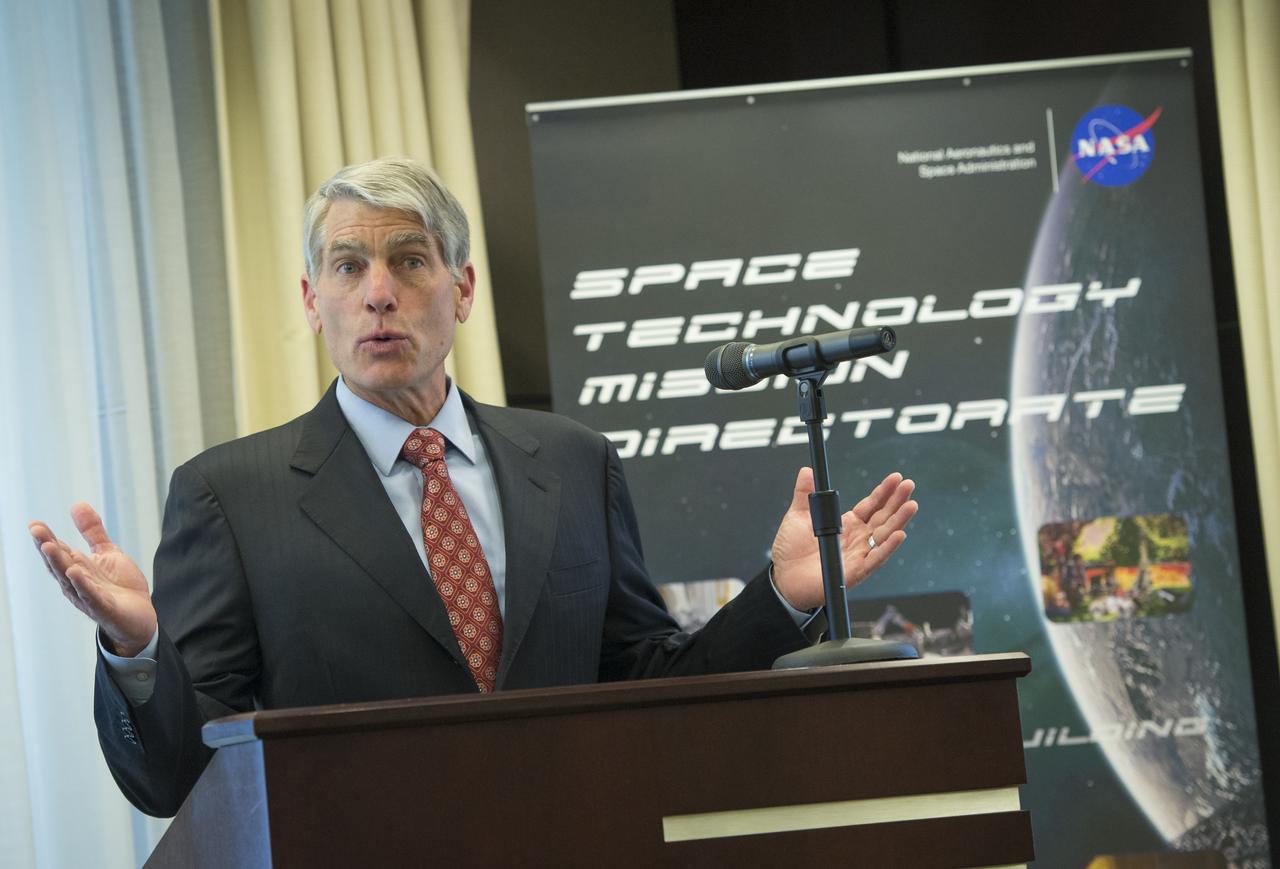
U.S. Senator Mark Udall (D-CO) speaks at a Green Propellant Infusion Mission press conference at the Reserve Officers Association, Tuesday, July 9, 2013 in Washington. The NASA GPIM program, led by Ball Aerospace in conjunction with Aerojet Rocketdyne, is demonstrating a high-performance "green" fuel in space. The propellant used on this mission offers nearly 50 percent better performance when compared to traditional hydrazine. Photo Credit: (NASA/Carla Cioffi)
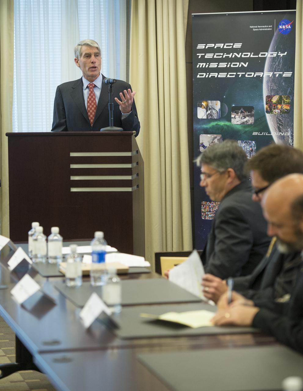
U.S. Senator Mark Udall (D-CO) speaks at a Green Propellant Infusion Mission press conference at the Reserve Officers Association, Tuesday, July 9, 2013 in Washington. The NASA GPIM program, led by Ball Aerospace in conjunction with Aerojet Rocketdyne, is demonstrating a high-performance "green" fuel in space. The propellant used on this mission offers nearly 50 percent better performance when compared to traditional hydrazine. Photo Credit: (NASA/Carla Cioffi)
Roger Myers, Executive Director, Aerojet Rocketdyne speaks at a Green Propellant Infusion Mission press conference at the Reserve Officers Association, Tuesday, July 9, 2013 in Washington. The NASA GPIM program, led by Ball Aerospace in conjunction with Aerojet Rocketdyne, is demonstrating a high-performance "green" fuel in space. The propellant used on this mission offers nearly 50 percent better performance when compared to traditional hydrazine. Photo Credit: (NASA/Carla Cioffi)
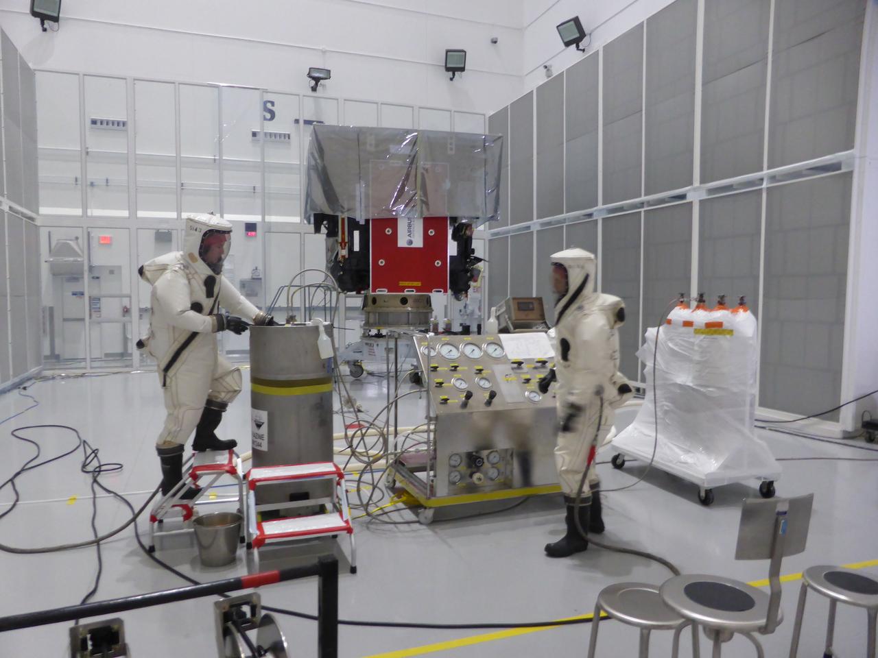
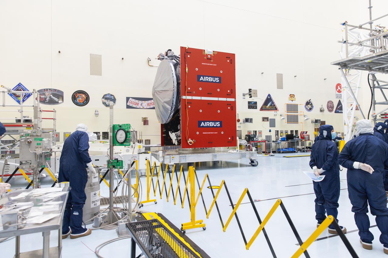
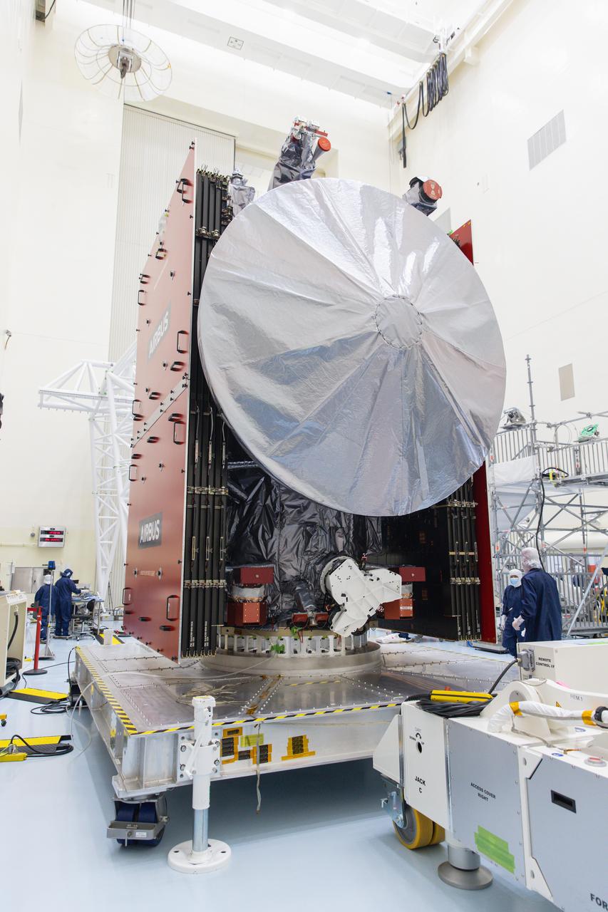
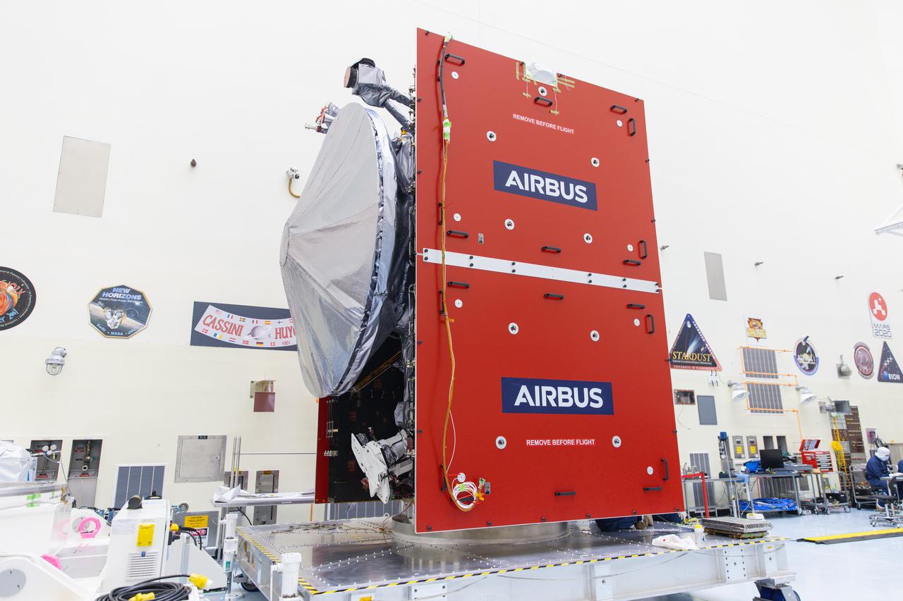
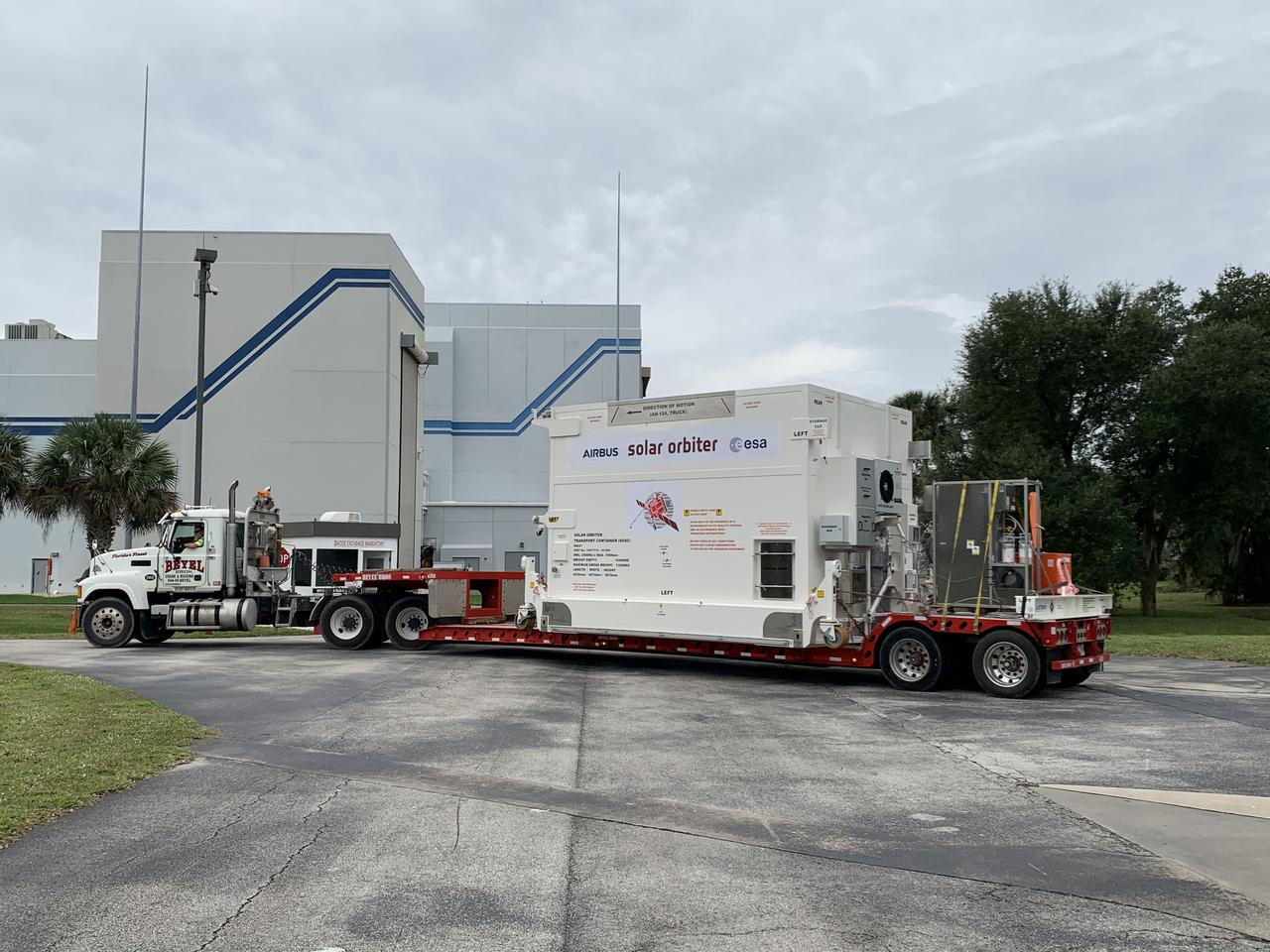
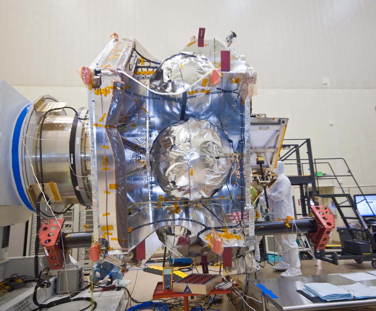
The Solar Orbiter spacecraft is loaded with propellants during processing activities inside the Astrotech Space Operations facility in Titusville, Florida. Solar Orbiter aims to study the Sun, its outer atmosphere and solar wind, and will provide the first images of the Sun’s poles. Solar Orbiter is a space mission of international collaboration between ESA (European Space Agency) and NASA. The spacecraft has been developed by Airbus. NASA’s Launch Services Program based at Kennedy Space Center in Florida is managing the launch. Liftoff is scheduled for Feb. 5, 2020, from Cape Canaveral Air Force Station aboard a United Launch Alliance Atlas V rocket.
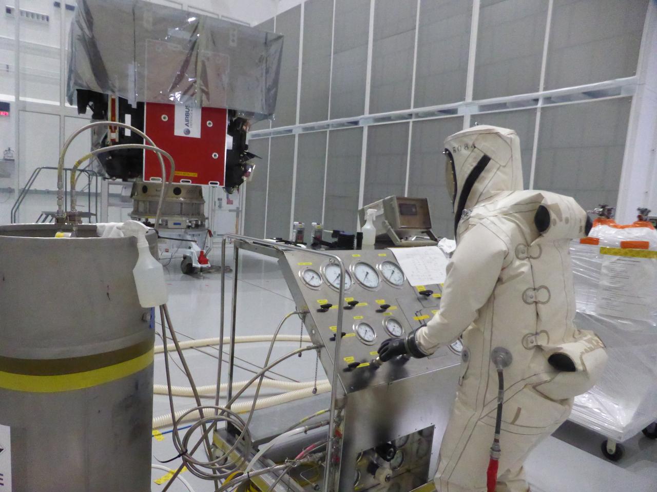
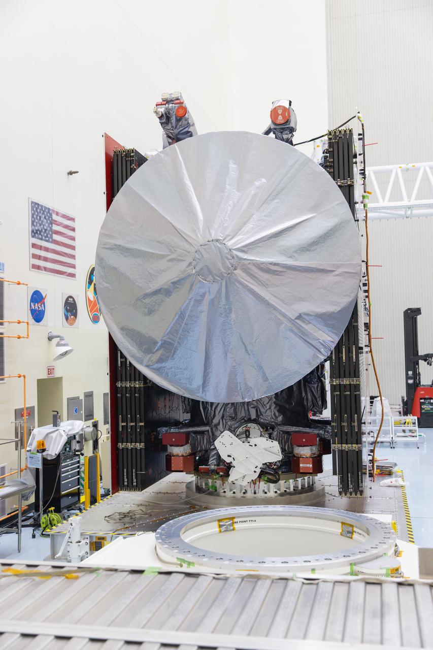
The Solar Orbiter spacecraft is loaded with propellants during processing activities inside the Astrotech Space Operations facility in Titusville, Florida. Solar Orbiter aims to study the Sun, its outer atmosphere and solar wind, and will provide the first images of the Sun’s poles. Solar Orbiter is a space mission of international collaboration between ESA (European Space Agency) and NASA. The spacecraft has been developed by Airbus. NASA’s Launch Services Program based at Kennedy Space Center in Florida is managing the launch. Liftoff is scheduled for Feb. 5, 2020, from Cape Canaveral Air Force Station aboard a United Launch Alliance Atlas V rocket.
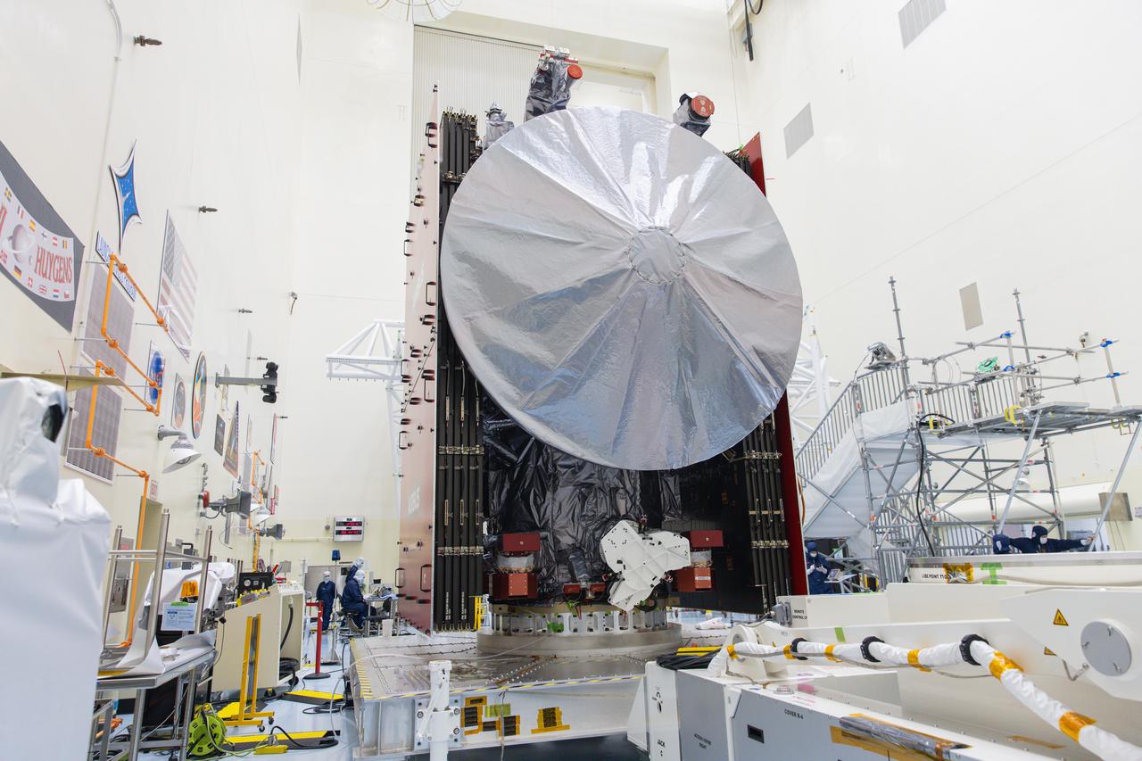
The Solar Orbiter spacecraft is loaded with propellants during processing activities inside the Astrotech Space Operations facility in Titusville, Florida. Solar Orbiter aims to study the Sun, its outer atmosphere and solar wind, and will provide the first images of the Sun’s poles. Solar Orbiter is a space mission of international collaboration between ESA (European Space Agency) and NASA. The spacecraft has been developed by Airbus. NASA’s Launch Services Program based at Kennedy Space Center in Florida is managing the launch. Liftoff is scheduled for Feb. 5, 2020, from Cape Canaveral Air Force Station aboard a United Launch Alliance Atlas V rocket.
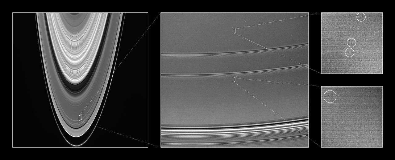
This collection of Cassini images provides context for understanding the location and scale of propeller-shaped features observed within Saturn A ring
This magnified view illustrates the general orientation of the propeller features in Saturn rings as they orbit the planet.

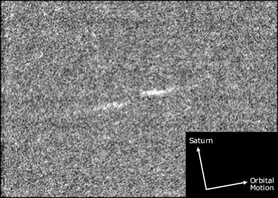
A propeller-shaped structure created by an unseen moon appears dark in this image obtained by NASA Cassini spacecraft of the unilluminated side of Saturn rings. The propeller is marked with a red arrow in the top left.

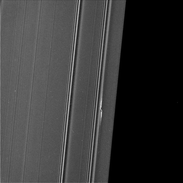
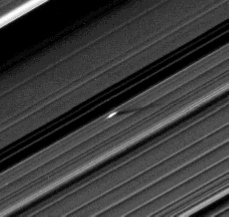
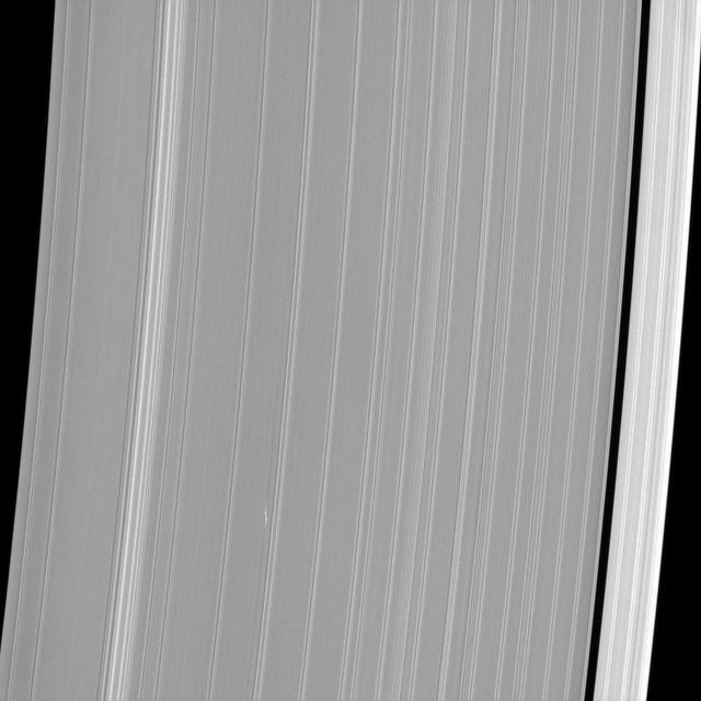
This view from NASA's Cassini spacecraft shows Cassini's best image of the propeller feature known informally as Bleriot. The propeller is named after Louis Bleriot, the French engineer and aviator who in 1909 was the first person to fly across the English Channel. This is the third and final propeller to be targeted for a close flyby observation during Cassini's ring-grazing orbits (the period from Nov. 2016 to April 2017 when Cassini's orbit passed just outside the main rings). Because propellers are seen in the outermost parts of the main rings, the ring-grazing orbits provided Cassini's best opportunity to see them up close. Many small, bright specks and linear, scratch-like artifacts are visible in the image. These artifacts are due to cosmic rays and particles of radiation near the planet striking the camera detector during the exposure. Bleriot is the largest of the propellers in Saturn's rings. The wavy features embedded in the propeller structure indicate that its central moonlet is some 60 percent wider than that of Santos-Dumont, which means the Bleriot moonlet is about four times more massive. Cassini scientists have been tracking the orbit of this object for the past decade, tracing the effect that the ring has upon it. Because it is the biggest propeller, it is more easily seen in lower-resolution images than other propellers, and thus it can be spotted in the most images by far. Here, as Cassini moved in close to the rings as part of its ring-grazing orbits, it was able to obtain this extreme close-up view of the propeller, which enables researchers to examine its effects on the ring as never before. These views, and others like them, will inform models and studies in new ways going forward. This image was taken on the unilluminated side of the rings, where sunlight filters through the backlit ring. Like a frosted window, Saturn's rings look different depending on whether they are seen fully sunlit or backlit. On the lit side, the rings look darker where there is less material to reflect sunlight. On the unlit side, some regions look darker because there is less material, but other regions look dark because there is so much material that the ring becomes opaque. Most dramatically in this image, a dark band cuts deeply through the middle of Bleriot's propeller. It is much more prominent than the similar dark band in the unlit-side image of the Santos-Dumont propeller, indicating that Bleriot stirs up the ring particles to much higher densities than does Santos-Dumont. The dark bands are regions where the density is so high that the ring becomes opaque to the sunlight filtering through the rings. As in Cassini's other propeller close-up images, the central moonlet itself seems to be obscured by the stirred-up ring material around it, so that it cannot be directly seen. It would be about three pixels across, and lies at the center of the propeller structure. The image was taken using the Cassini spacecraft's narrow-angle camera on April 12. Image scale in this view is 0.3 mile (500 meters) per pixel. The sun-ring-spacecraft angle, or phase angle, is 83 degrees. https://photojournal.jpl.nasa.gov/catalog/PIA21447
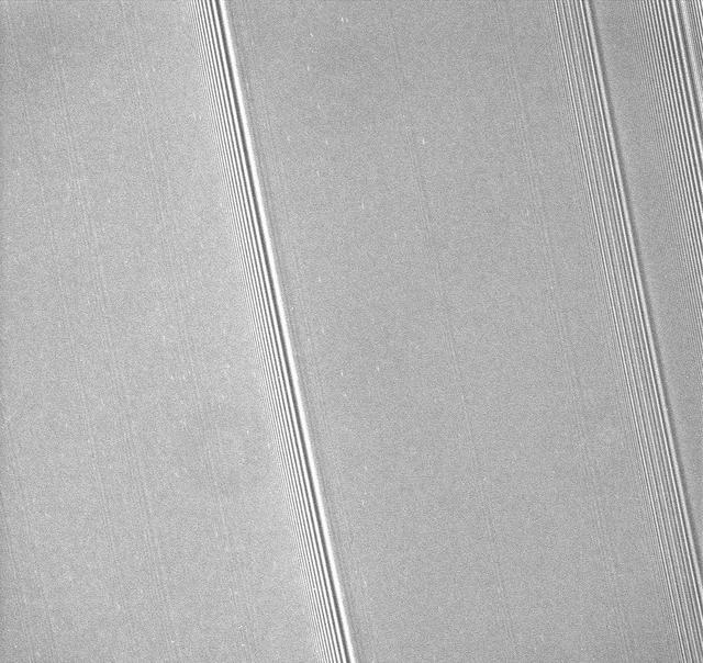
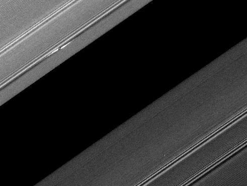
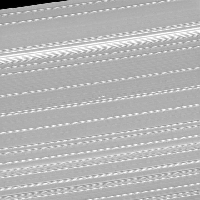
This view from NASA's Cassini spacecraft is the sharpest ever taken of belts of the features called propellers in the middle part of Saturn's A ring. The propellers are the small, bright features that look like double dashes, visible on both sides of the wave pattern that crosses the image diagonally from top to bottom. The original discovery of propellers in this region in Saturn's rings was made using several images taken from very close to the rings during Cassini's 2004 arrival at Saturn. Those discovery images were of low resolution and were difficult to interpret, and there were few clues as to how the small propellers seen in those images were related to the larger propellers Cassini observed later in the mission. This image, for the first time, shows swarms of propellers of a wide range of sizes, putting the ones Cassini observed in its Saturn arrival images in context. Scientists will use this information to derive a "particle size distribution" for propeller moons, which is an important clue to their origins. The image was taken using the Cassini spacecraft's narrow-angle camera on April 19. The view was has an image scale of 0.24 mile (385 meters) per pixel, and was taken at a sun-ring-spacecraft angle, or phase angle, of 108 degrees. The view looks toward a point approximately 80,000 miles (129,000 kilometers) from Saturn's center. https://photojournal.jpl.nasa.gov/catalog/PIA21448

NASA Cassini spacecraft captured a propeller-shaped disturbance in one of Saturn rings created by a moon that is too small to be seen here. The moon is invisible at the center of the image.
Counter Rotating Propeller Model in the NASA Glenn 8x6-Foot Supersonic Wind Tunnel
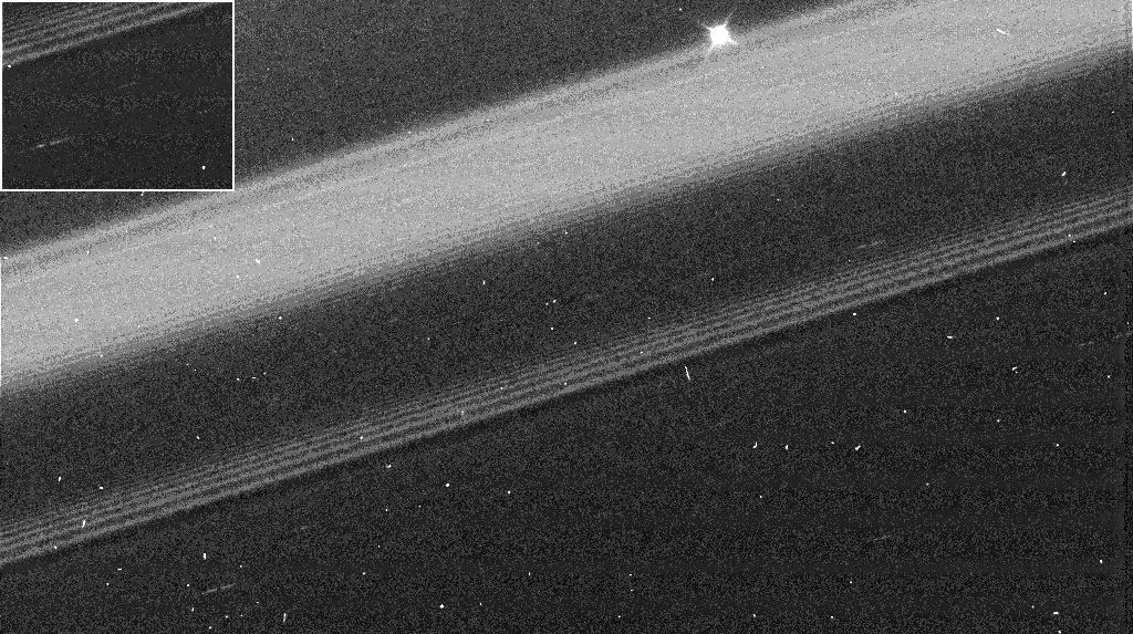
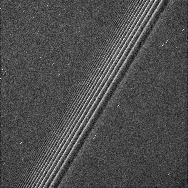
The propeller informally named "Earhart" is seen in this view from NASA's Cassini spacecraft at much higher resolution than ever before. This view, obtained on March 22, 2017, is the second time Cassini has deliberately targeted an individual propeller for close-up viewing during its ring-grazing orbits, after its images of Santos-Dumont (PIA21433) a month earlier. The biggest known propeller, informally named "Bleriot," is slated for the third and final propeller close-up in April 2017. Propellers are disturbances in the ring caused by a central moonlet. The moonlet itself would be a few pixels wide in this view, but it is difficult to distinguish from (and may be obscured by) the disturbed ring material that surrounds it. (See PIA20525 for more info on propellers.) The detailed structure of the Earhart propeller, as seen here, differs from that of Santos-Dumont. It is not clear whether these differences have to do with intrinsic differences between Earhart and Santos-Dumont, or whether they have to do with different viewing angles or differences in where the propellers were imaged in their orbits around Saturn. Earhart is situated very close to the 200-mile-wide (320-kilometer-wide) Encke Gap, which is held open by the much larger moon Pan. In this view, half of the Encke Gap is visible as the dark region at right. The gap and the propeller are a study in contrasts. The propeller is nothing more than Earhart's attempt to open a gap like Encke using its gravity. However, Earhart's attempt is thwarted by the mass of the ring, which fills in the nascent gap before it can extend very far. Pan is a few thousand times more massive than Earhart, which enables it to maintain a gap that extends all the way around the ring. To the left of the propeller are wave features in the rings caused by the moons Pandora, Prometheus and Pan. The visible-light image was acquired by the Cassini narrow-angle camera at a distance of 69,183 miles (111,340 kilometers) from the propeller feature. Image scale is 0.4 mile (670 meters) per pixel in the radial, or outward-from-Saturn, direction. The view looks toward the sunlit side of the rings. https://photojournal.jpl.nasa.gov/catalog/PIA21437
A propeller-shaped structure created by an unseen moon is brightly illuminated on the sunlit side of Saturn rings in this image obtained by NASA Cassini spacecraft. The moon, which is too small to be seen, is marked with a red arrow.

A propeller-shaped structure, created by an unseen moon, can be seen in Saturn A ring and looks like a small, dark line interrupting the bright surrounding ring material in the upper left of this image taken by NASA Cassini spacecraft.
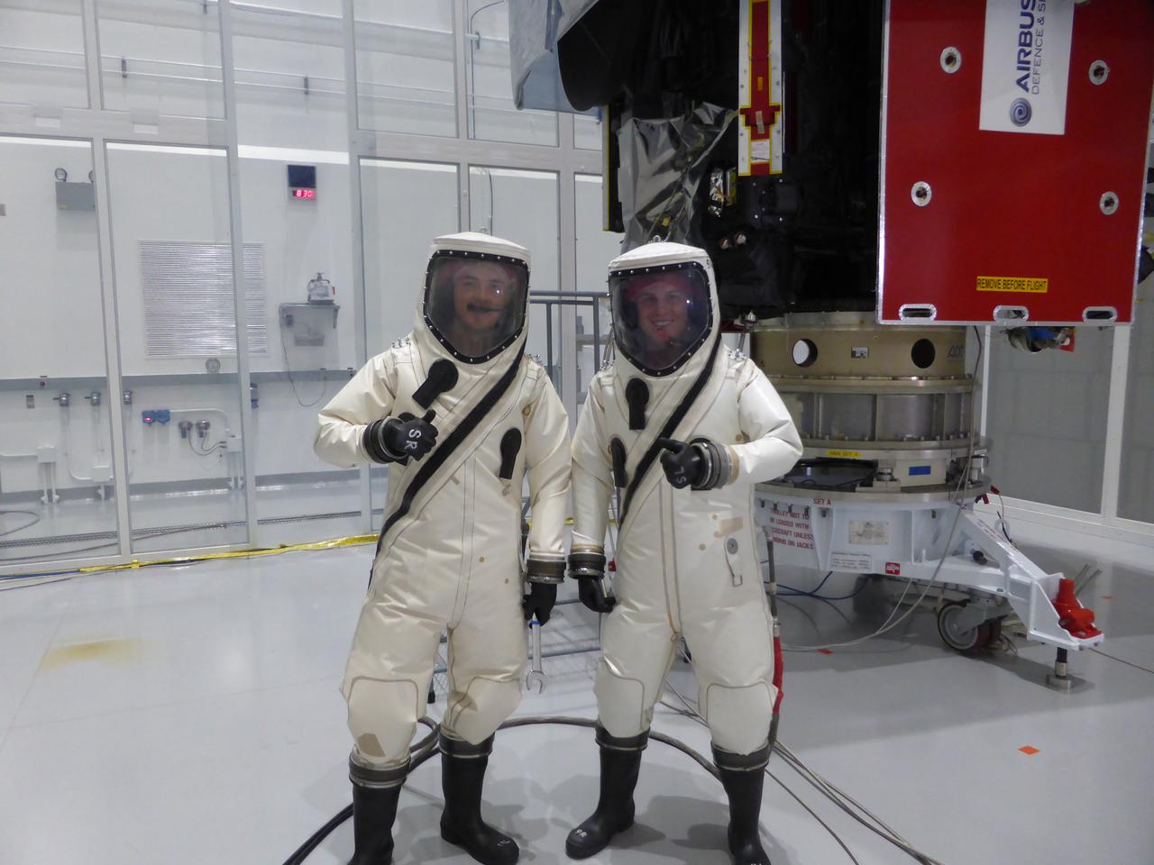
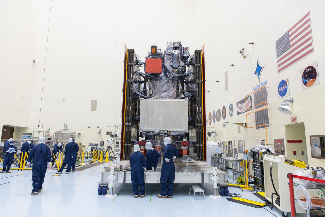
Members of the Airbus team preparing the Solar Orbiter spacecraft for launch pause for a photo inside the Astrotech Space Operations facility in Titusville, Florida. Solar Orbiter aims to study the Sun, its outer atmosphere and solar wind, and will provide the first images of the Sun’s poles. Solar Orbiter is a space mission of international collaboration between ESA (European Space Agency) and NASA. The spacecraft has been developed by Airbus. NASA’s Launch Services Program based at Kennedy Space Center in Florida is managing the launch. Liftoff is scheduled for Feb. 5, 2020, from Cape Canaveral Air Force Station aboard a United Launch Alliance Atlas V rocket.
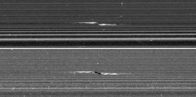
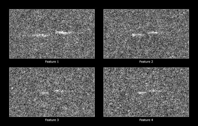
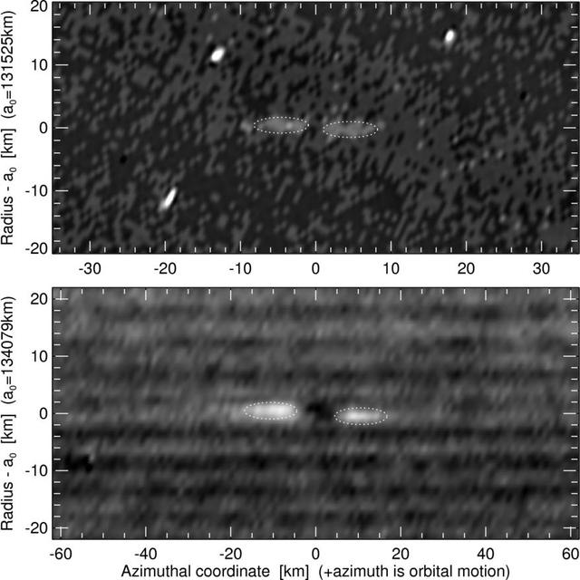
NASA's Cassini spacecraft captured these remarkable views of a propeller feature in Saturn's A ring on Feb. 21, 2017. These are the sharpest images taken of a propeller so far, and show an unprecedented level of detail. The propeller is nicknamed "Santos-Dumont," after the pioneering Brazilian-French aviator. This observation was Cassini's first targeted flyby of a propeller. The views show the object from vantage points on opposite sides of the rings. The top image looks toward the rings' sunlit side, while the bottom image shows the unilluminated side, where sunlight filters through the backlit ring. The two images presented as figure 1 are reprojected at the same scale (0.13 mile or 207 meters per pixel) in order to facilitate comparison. The original images, which have slightly different scales, are also provided here, without reprojection, as figure 2; the sunlit-side image is at left, while the unlit-side image is at right. Cassini scientists have been tracking the orbit of this object for the past decade, tracing the effect that the ring has upon it. Now, as Cassini has moved in close to the ring as part of its ring-grazing orbits, it was able to obtain this extreme close-up view of the propeller, enabling researchers to examine its effects on the ring. These views, and others like them, will inform models and studies in new ways going forward. Like a frosted window, Saturn's rings look different depending on whether they are seen fully sunlit or backlit. On the lit side, the rings look darker where there is less material to reflect sunlight. On the unlit side, some regions look darker because there is less material, but other regions look dark because there is so much material that the ring becomes opaque. Observing the same propeller on both the lit and unlit sides allows scientists to gather richer information about how the moonlet affects the ring. For example, in the unlit-side view, the broad, dark band through the middle of the propeller seems to be a combination of both empty and opaque regions. The propeller's central moonlet would only be a couple of pixels across in these images, and may not actually be resolved here. The lit-side image shows that a bright, narrow band of material connects the moonlet directly to the larger ring, in agreement with dynamical models. That same thin band of material may also be obscuring the moonlet from view. Lengthwise along the propeller is a gap in the ring that the moonlet has pried open. The gap appears dark on both the lit and unlit sides. Flanking the gap near the moonlet are regions of enhanced density, which appear bright on the lit side and more mottled on the unlit side. One benefit of the high resolution of these images is that, for the first time, wavy edges are clearly visible in the gap. These waves are also expected from dynamical models, and they emphasize that the gap must be sharp-edged. Furthermore, the distance between the wave crests tells scientists the width of the gap (1.2 miles or 2 kilometers), which in turn reveals the mass of the central moonlet. From these measurements, Cassini imaging scientists deduce that the moonlet's mass is comparable to that of a snowball about 0.6 mile (1 kilometer) wide. For the original images, the lit-side image has a scale of 0.33 mile (530 meters) per pixel in the radial (or outward from Saturn) direction and 0.44 mile (710 meters) per pixel in the azimuthal (or around Saturn) direction. The different scales are the result of Cassini's vantage point being off to the side of the propeller, rather than directly above it. The unlit-side image has a scale of 0.25 (410 meters) per pixel in both directions. In order to preserve its original level of detail, the image has not been cleaned of bright blemishes due to cosmic rays and to charged particle radiation from Saturn. http://photojournal.jpl.nasa.gov/catalog/PIA21433

This view of Saturn's A ring features a lone "propeller" -- one of many such features created by small moonlets embedded in the rings as they attempt, unsuccessfully, to open gaps in the ring material. The image was taken by NASA's Cassini spacecraft on Sept. 13, 2017. It is among the last images Cassini sent back to Earth. The view was taken in visible light using the Cassini spacecraft wide-angle camera at a distance of 420,000 miles (676,000 kilometers) from Saturn. Image scale is 2.3 miles (3.7 kilometers). https://photojournal.jpl.nasa.gov/catalog/PIA21894
An unusually large propeller feature is detected just beyond the Encke Gap in this Cassini image of Saturn’s outer A ring taken a couple days after the planet’s August 2009 equinox.

This image is part of a set of images obtained by NASA Cassini spacecraft showing a propeller-shaped structure created by a hidden, embedded moon moving through one of Saturn rings. An animation is available at the Photojournal.
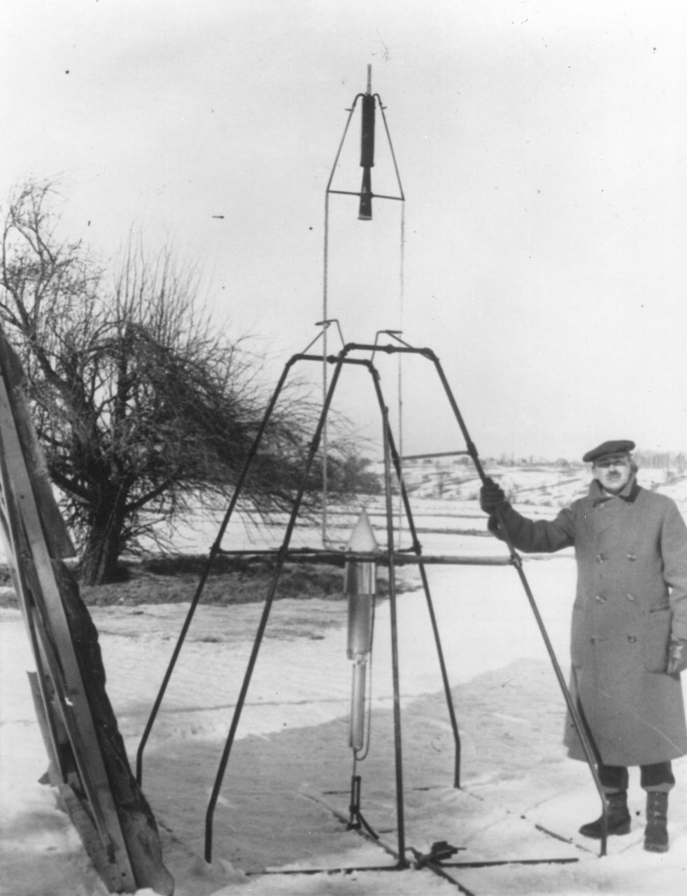
Dr. Robert H. Goddard and a liquid oxygen-gasoline rocket in the frame from which it was fired on March 16, 1926, at Auburn, Massachusetts. From 1930 to 1941, Dr. Goddard made substantial progress in the development of progressively larger rockets, which attained altitudes of 2400 meters, and refined his equipment for guidance and control, his techniques of welding, and his insulation, pumps and other associated equipment. In many respects, Dr. Goddard laid the essential foundations of practical rocket technology. He is considered one of the fathers of rocketry along with Konstantin Tsiolovsky (1857-1935) and Hermann Oberth (1894-1989). <b><a href="http://www.nasa.gov/centers/goddard/home/index.html" rel="nofollow">NASA Goddard Space Flight Center</a></b> enables NASA’s mission through four scientific endeavors: Earth Science, Heliophysics, Solar System Exploration, and Astrophysics. Goddard plays a leading role in NASA’s accomplishments by contributing compelling scientific knowledge to advance the Agency’s mission. <b>Follow us on <a href="http://twitter.com/NASA_GoddardPix" rel="nofollow">Twitter</a></b> <b>Join us on <a href="http://www.facebook.com/pages/Greenbelt-MD/NASA-Goddard/395013845897?ref=tsd" rel="nofollow">Facebook</a></b>

HUU TRINH POSES WITH A HYPERGOLIC BI-PROPELLANT THRUSTER FOR A POTENTIAL APPLICATION ON FUTURE ROBOTIC LUNAR SPACECRAFTS.

HUU TRINH POSES WITH A HYPERGOLIC BI-PROPELLANT THRUSTER FOR A POTENTIAL APPLICATION ON FUTURE ROBOTIC LUNAR SPACECRAFTS.
NASA Cassini spacecraft has been monitoring propeller features such as Bleriot since their discovery. The bright dash-like features are regions where a small moonlet has caused ring particles to cluster together more densely than normal.

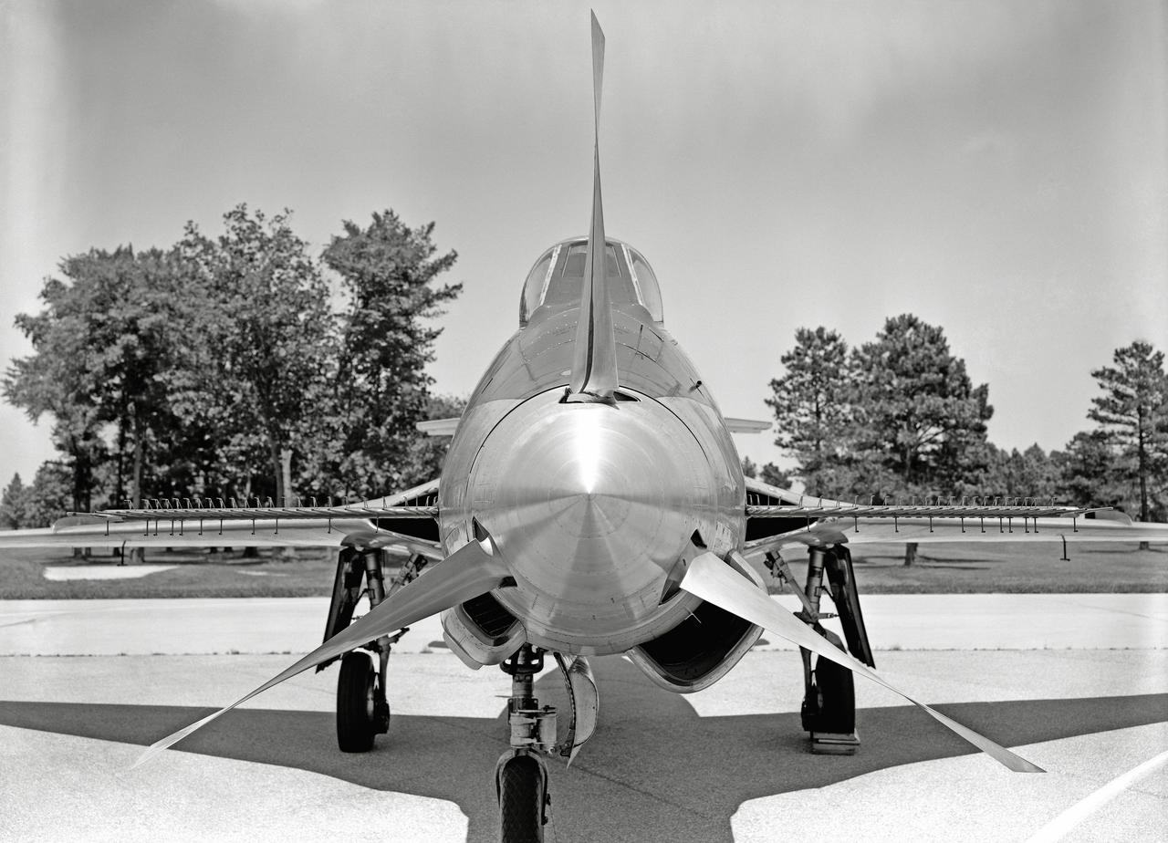
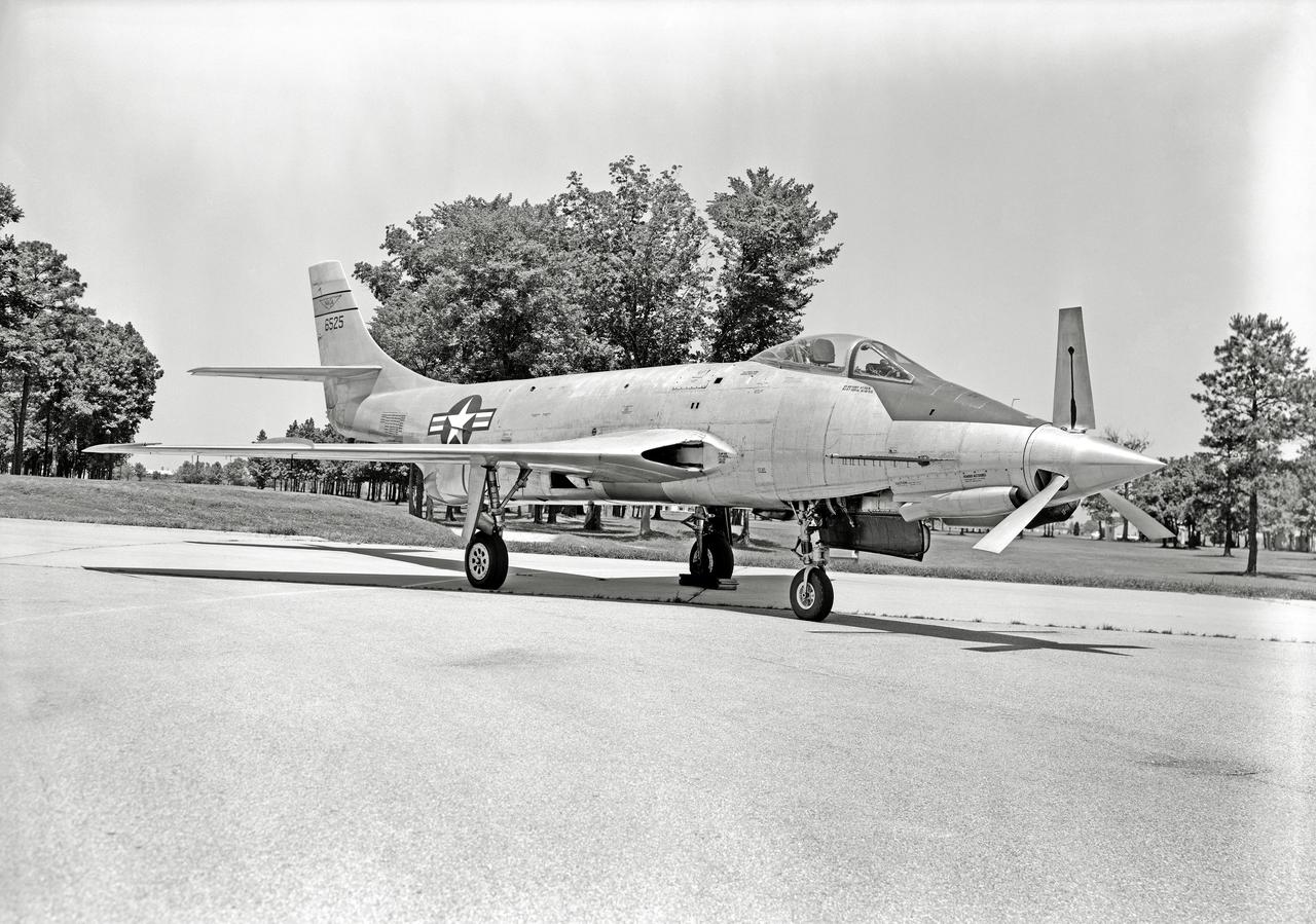
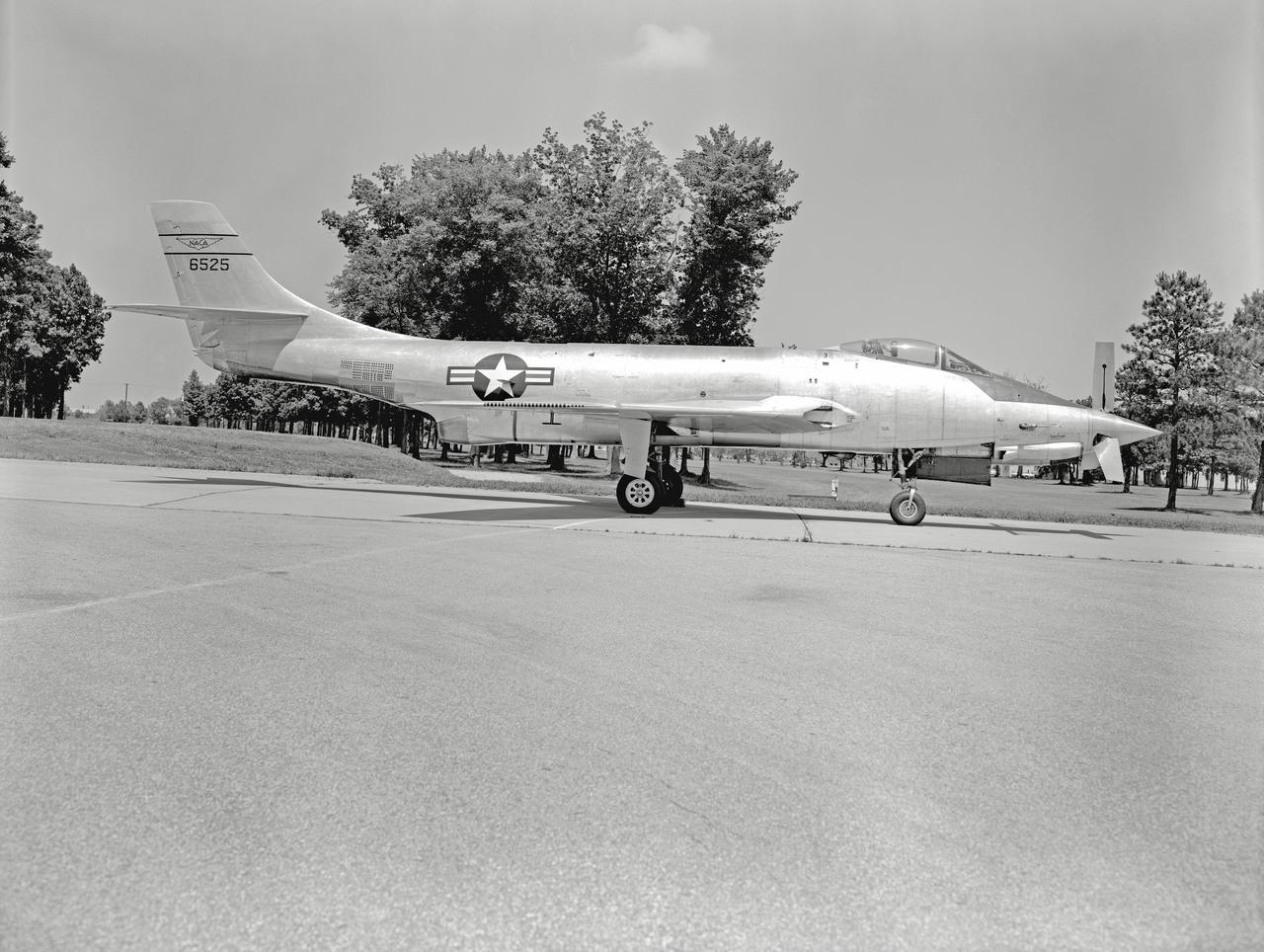
Phase SB Propeller installed on F88B
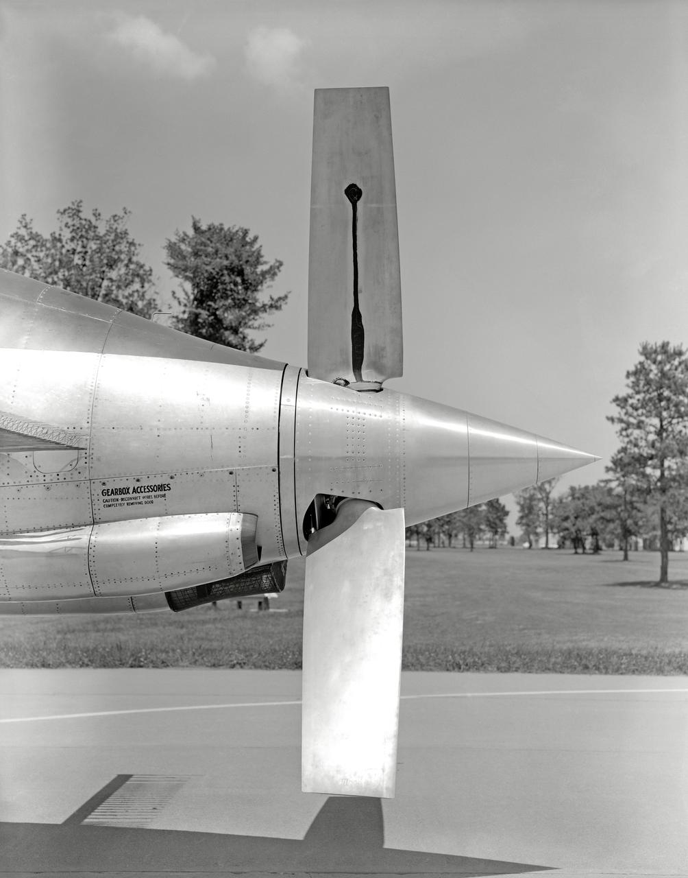
Phase SB Propeller installed on F88B
Phase SB Propeller installed on F88B
Phase SB Propeller installed on F88B
Phase SB Propeller installed on F88B
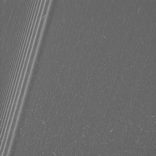
This image from NASA's Cassini mission shows a region in Saturn's A ring. The level of detail is twice as high as this part of the rings has ever been seen before. The view contains many small, bright blemishes due to cosmic rays and charged particle radiation near the planet. The view shows a section of the A ring known to researchers for hosting belts of propellers -- bright, narrow, propeller-shaped disturbances in the ring produced by the gravity of unseen embedded moonlets. Several small propellers are visible in this view. These are on the order of 10 times smaller than the large, bright propellers whose orbits scientists have routinely tracked (and which are given nicknames for famous aviators). This image is a lightly processed version, with minimal enhancement, preserving all original details present in the image. he image was taken in visible light with the Cassini spacecraft wide-angle camera on Dec. 18, 2016. The view was obtained at a distance of approximately 33,000 miles (54,000 kilometers) from the rings and looks toward the unilluminated side of the rings. Image scale is about a quarter-mile (330 meters) per pixel. http://photojournal.jpl.nasa.gov/catalog/PIA21059
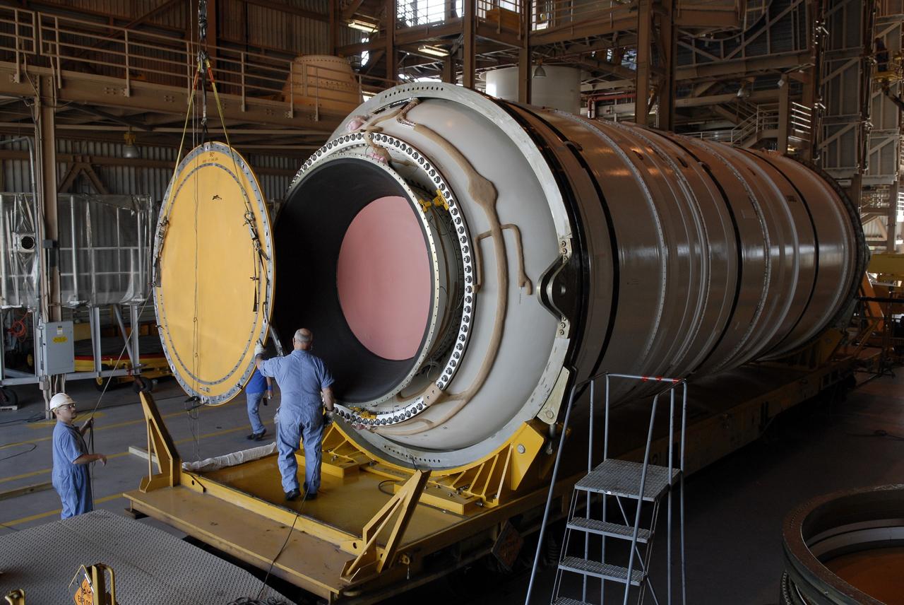
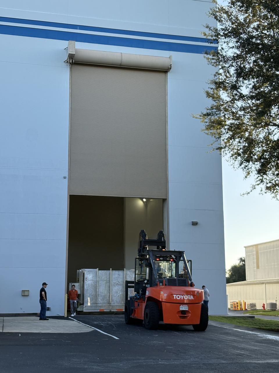
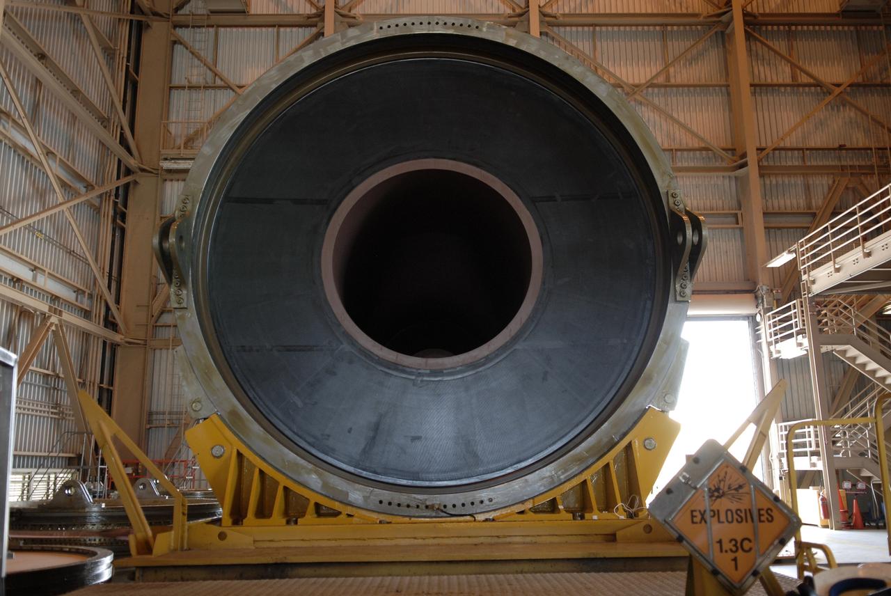
CAPE CANAVERAL, Fla. –In the Rotation, Processing and Surge Facility at NASA's Kennedy Space Center in Florida, the end of the Ares I-X motor segment is removed to allow propellant grain inspection of the interior. It is one of four reusable motor segments and nozzle exit cone shipped by the Ares I first-stage prime contractor Alliant Techsystems Inc. for final processing and integration in the facility. The booster used for the Ares I-X launch is being modified by adding new forward structures and a fifth segment simulator. The motor is the final hardware needed for the rocket's upcoming flight test this summer. The stacking operations are scheduled to begin in the Vehicle Assembly Building in April. Photo credit: NASA/Jim Grossmann
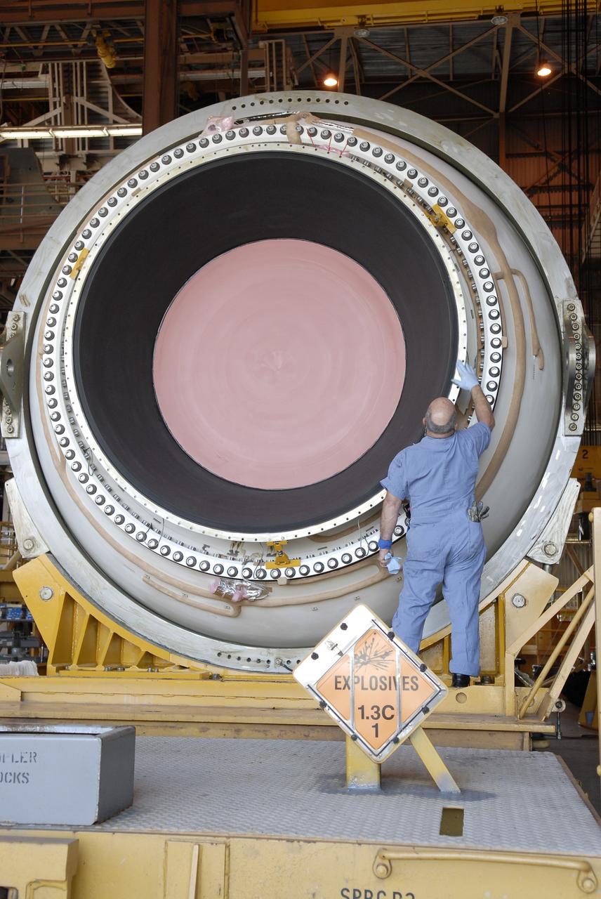
CAPE CANAVERAL, Fla. – In the Rotation, Processing and Surge Facility at NASA's Kennedy Space Center in Florida, a technician begins propellant grain inspection of the interior of the Ares I-X motor segment. It is one of four reusable motor segments and nozzle exit cone shipped by the Ares I first-stage prime contractor Alliant Techsystems Inc. for final processing and integration in the facility. The booster used for the Ares I-X launch is being modified by adding new forward structures and a fifth segment simulator. The motor is the final hardware needed for the rocket's upcoming flight test this summer. The stacking operations are scheduled to begin in the Vehicle Assembly Building in April. Photo credit: NASA/Jim Grossmann

CAPE CANAVERAL, Fla. – In the Rotation, Processing and Surge Facility at NASA's Kennedy Space Center in Florida, a technician performs propellant grain inspection of the inside of the Ares I-X motor segment. It is one of four reusable motor segments and nozzle exit cone shipped by the Ares I first-stage prime contractor Alliant Techsystems Inc. for final processing and integration in the facility. The booster used for the Ares I-X launch is being modified by adding new forward structures and a fifth segment simulator. The motor is the final hardware needed for the rocket's upcoming flight test this summer. The stacking operations are scheduled to begin in the Vehicle Assembly Building in April. Photo credit: NASA/Jim Grossmann
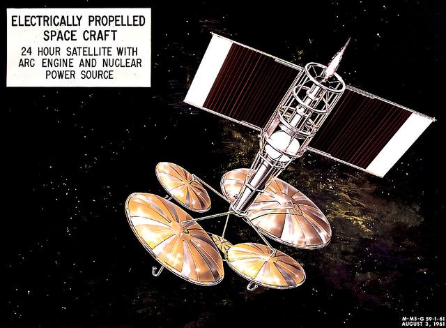
This 1960 artist's concept shows a 24-hour communication satellite design incorporating an arc engine with a nuclear power source. The concept was one of many missions proposed by the Marshall Space Flight Center for electrically-propelled spacecraft.
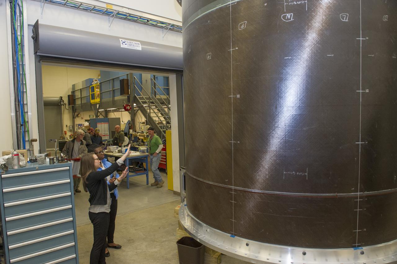
MICHELLE TILLOTSON, AN ENGINEER AT NASA’S MARSHALL SPACE FLIGHT CENTER, SHOWS KALYN HOPKINS A STUDENT AT THE MIAMI VALLEY SCHOOL, DAYTON OHIO, NEW EQUIPMENT THAT WILL BE USED TO TEST THE PROPELLANT TANKS FOR THE SLS
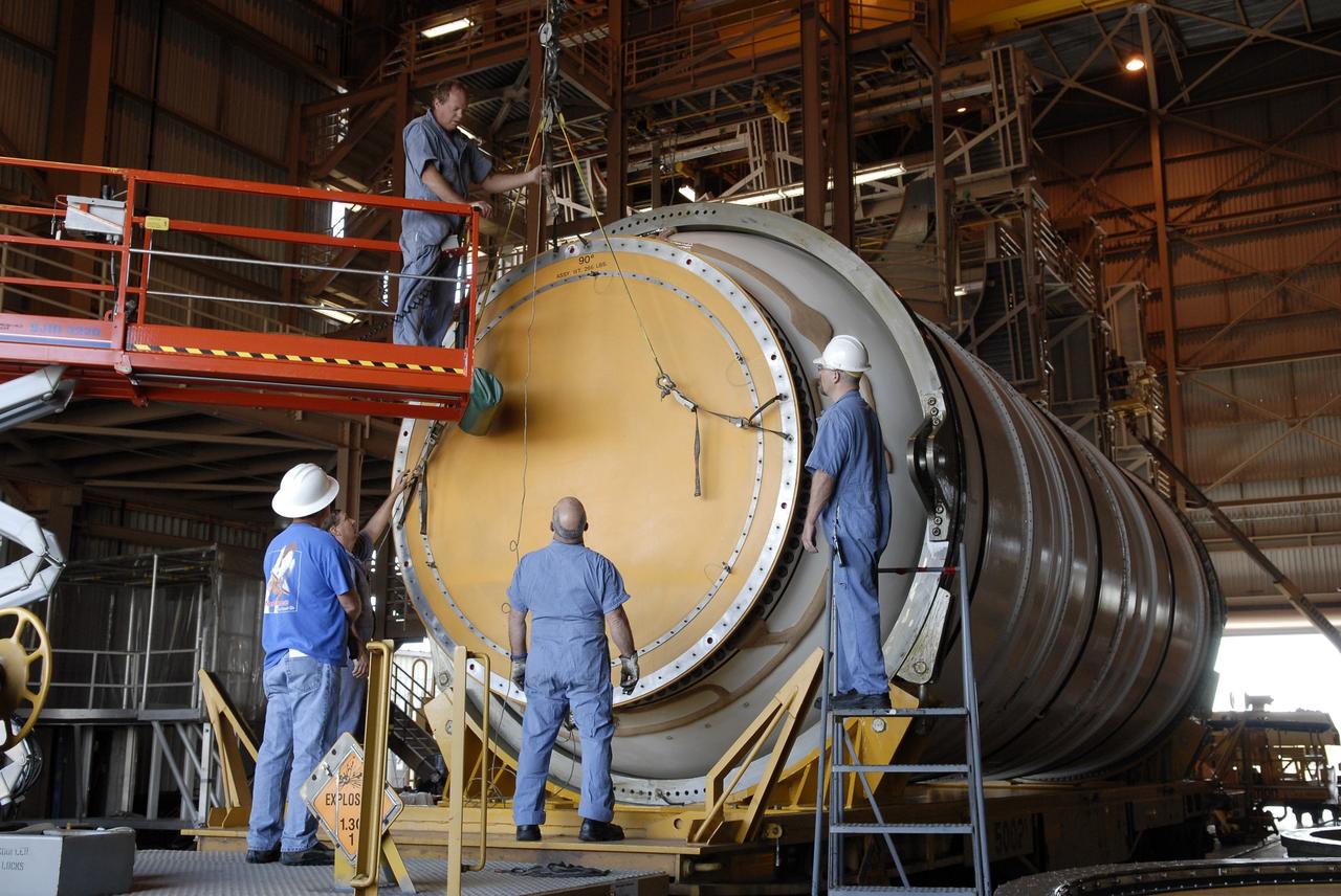
CAPE CANAVERAL, Fla. – In the Rotation, Processing and Surge Facility at NASA's Kennedy Space Center in Florida, technicians prepare to remove the cover from the end of the Ares I-X motor segment for propellant grain inspection of the interior. It is one of four reusable motor segments and nozzle exit cone shipped by the Ares I first-stage prime contractor Alliant Techsystems Inc. for final processing and integration in the facility. The booster used for the Ares I-X launch is being modified by adding new forward structures and a fifth segment simulator. The motor is the final hardware needed for the rocket's upcoming flight test this summer. The stacking operations are scheduled to begin in the Vehicle Assembly Building in April. Photo credit: NASA/Jim Grossmann

Artemis I Launch Director Charlie Blackwell-Thompson leads a cryogenic propellant tanking demonstration inside Firing Room 1 of the Rocco A. Petrone Launch Control Center at NASA’s Kennedy Space Center in Florida on Sept. 21, 2022. The first in a series of increasingly complex missions, Artemis I will provide a foundation for human deep space exploration and demonstrate our commitment and capability to extend human presence to the Moon and beyond. The primary goal of Artemis I is to thoroughly test the integrated systems before crewed missions by operating the spacecraft in a deep space environment, testing Orion’s heat shield, and recovering the crew module after reentry, descent, and splashdown.
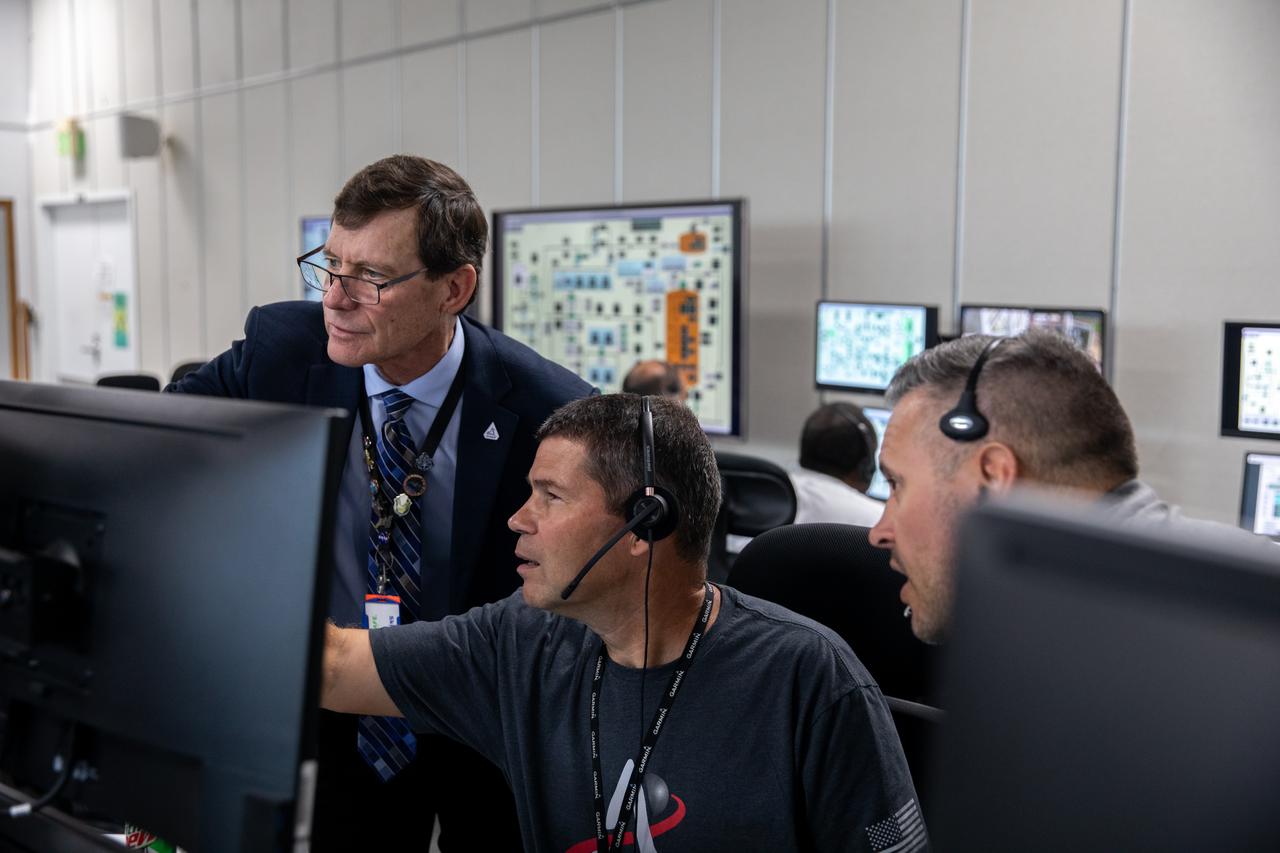
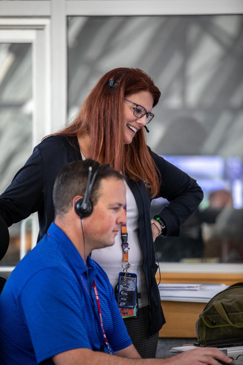
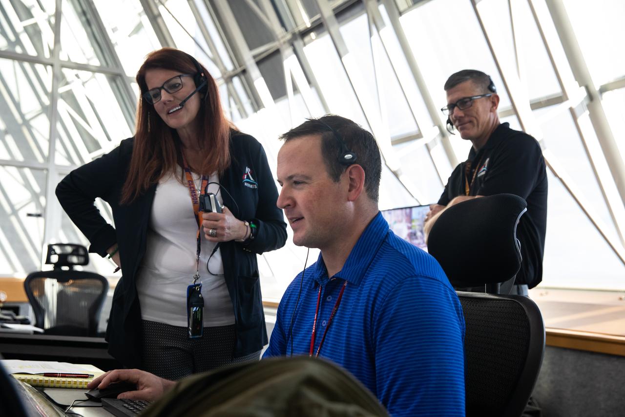
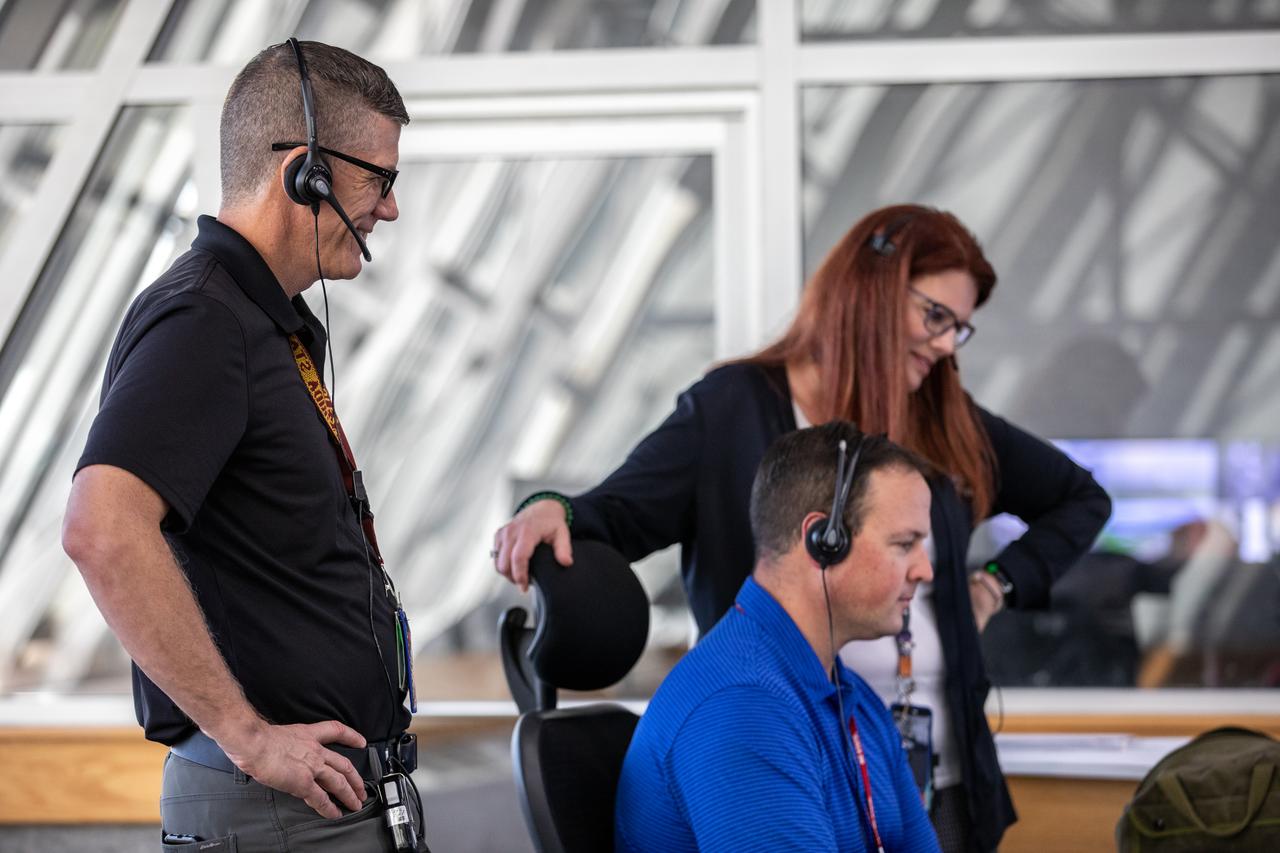
Members of the Artemis I launch team monitor data at their consoles inside Firing Room 1 of the Rocco A. Petrone Launch Control Center at NASA’s Kennedy Space Center in Florida during a cryogenic propellant tanking demonstration on Sept. 21, 2022. The first in a series of increasingly complex missions, Artemis I will provide a foundation for human deep space exploration and demonstrate our commitment and capability to extend human presence to the Moon and beyond. The primary goal of Artemis I is to thoroughly test the integrated systems before crewed missions by operating the spacecraft in a deep space environment, testing Orion’s heat shield, and recovering the crew module after reentry, descent, and splashdown.

Artemis I Assistant Launch Director Jeremy Graeber helps lead a cryogenic propellant tanking demonstration inside Firing Room 1 of the Rocco A. Petrone Launch Control Center at NASA’s Kennedy Space Center in Florida on Sept. 21, 2022. The first in a series of increasingly complex missions, Artemis I will provide a foundation for human deep space exploration and demonstrate our commitment and capability to extend human presence to the Moon and beyond. The primary goal of Artemis I is to thoroughly test the integrated systems before crewed missions by operating the spacecraft in a deep space environment, testing Orion’s heat shield, and recovering the crew module after reentry, descent, and splashdown.

Members of the Artemis I launch team monitor data at their consoles inside Firing Room 1 of the Rocco A. Petrone Launch Control Center at NASA’s Kennedy Space Center in Florida during a cryogenic propellant tanking demonstration on Sept. 21, 2022. The first in a series of increasingly complex missions, Artemis I will provide a foundation for human deep space exploration and demonstrate our commitment and capability to extend human presence to the Moon and beyond. The primary goal of Artemis I is to thoroughly test the integrated systems before crewed missions by operating the spacecraft in a deep space environment, testing Orion’s heat shield, and recovering the crew module after reentry, descent, and splashdown.

Members of the Artemis I launch team monitor data at their consoles inside Firing Room 1 of the Rocco A. Petrone Launch Control Center at NASA’s Kennedy Space Center in Florida during a cryogenic propellant tanking demonstration on Sept. 21, 2022. The first in a series of increasingly complex missions, Artemis I will provide a foundation for human deep space exploration and demonstrate our commitment and capability to extend human presence to the Moon and beyond. The primary goal of Artemis I is to thoroughly test the integrated systems before crewed missions by operating the spacecraft in a deep space environment, testing Orion’s heat shield, and recovering the crew module after reentry, descent, and splashdown.
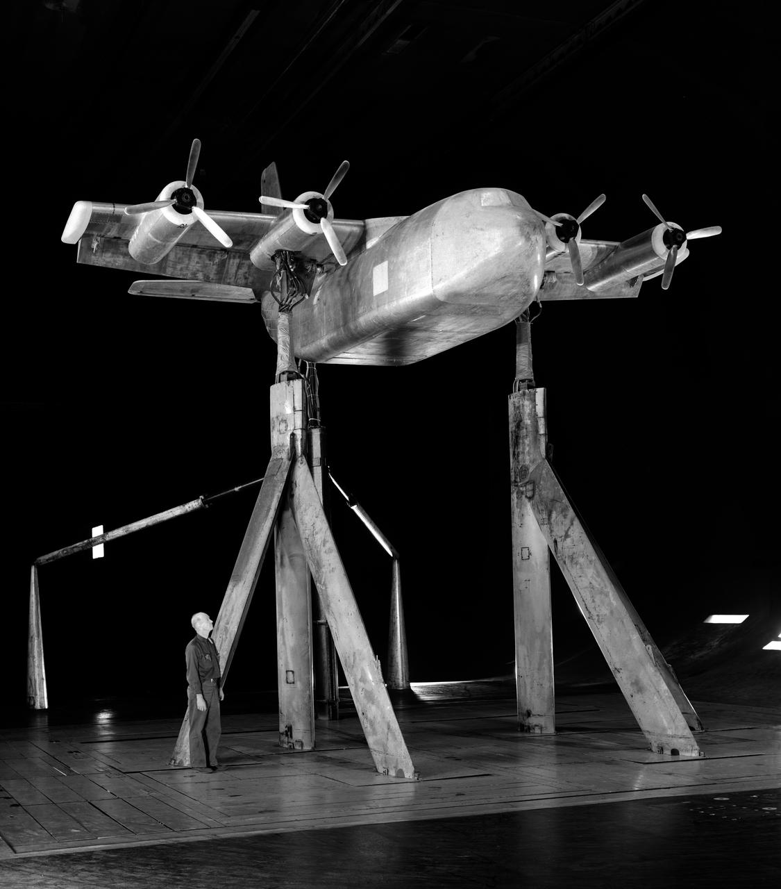
Investigation of a tilt-wing/propeller model with blowing flaps. 3/4 front view, tilt wing model, wing position = 0deg. C-123 fuselage, conventional struts, 4 props
Artemis I Launch Director Charlie Blackwell-Thompson, standing, leads a cryogenic propellant tanking demonstration inside Firing Room 1 of the Rocco A. Petrone Launch Control Center at NASA’s Kennedy Space Center in Florida on Sept. 21, 2022. Seated at his console is Wes Mosedale, technical assistant to the launch director. The first in a series of increasingly complex missions, Artemis I will provide a foundation for human deep space exploration and demonstrate our commitment and capability to extend human presence to the Moon and beyond. The primary goal of Artemis I is to thoroughly test the integrated systems before crewed missions by operating the spacecraft in a deep space environment, testing Orion’s heat shield, and recovering the crew module after reentry, descent, and splashdown.
Artemis I Launch Director Charlie Blackwell-Thompson, at left, monitors data inside Firing Room 1 of the Rocco A. Petrone Launch Control Center at NASA’s Kennedy Space Center in Florida during a cryogenic propellant tanking demonstration on Sept. 21, 2022. At right is Wes Mosedale, technical assistant to the launch director. Behind them is Jeremy Graeber, Artemis I assistant launch director. The first in a series of increasingly complex missions, Artemis I will provide a foundation for human deep space exploration and demonstrate our commitment and capability to extend human presence to the Moon and beyond. The primary goal of Artemis I is to thoroughly test the integrated systems before crewed missions by operating the spacecraft in a deep space environment, testing Orion’s heat shield, and recovering the crew module after reentry, descent, and splashdown.
Artemis I Launch Director Charlie Blackwell-Thompson, at right, monitors data inside Firing Room 1 of the Rocco A. Petrone Launch Control Center at NASA’s Kennedy Space Center in Florida during a cryogenic propellant tanking demonstration on Sept. 21, 2022. Seated at his console is Wes Mosedale, technical assistant to the launch director. At left is Jeremy Graeber, Artemis I assistant launch director. The first in a series of increasingly complex missions, Artemis I will provide a foundation for human deep space exploration and demonstrate our commitment and capability to extend human presence to the Moon and beyond. The primary goal of Artemis I is to thoroughly test the integrated systems before crewed missions by operating the spacecraft in a deep space environment, testing Orion’s heat shield, and recovering the crew module after reentry, descent, and splashdown.
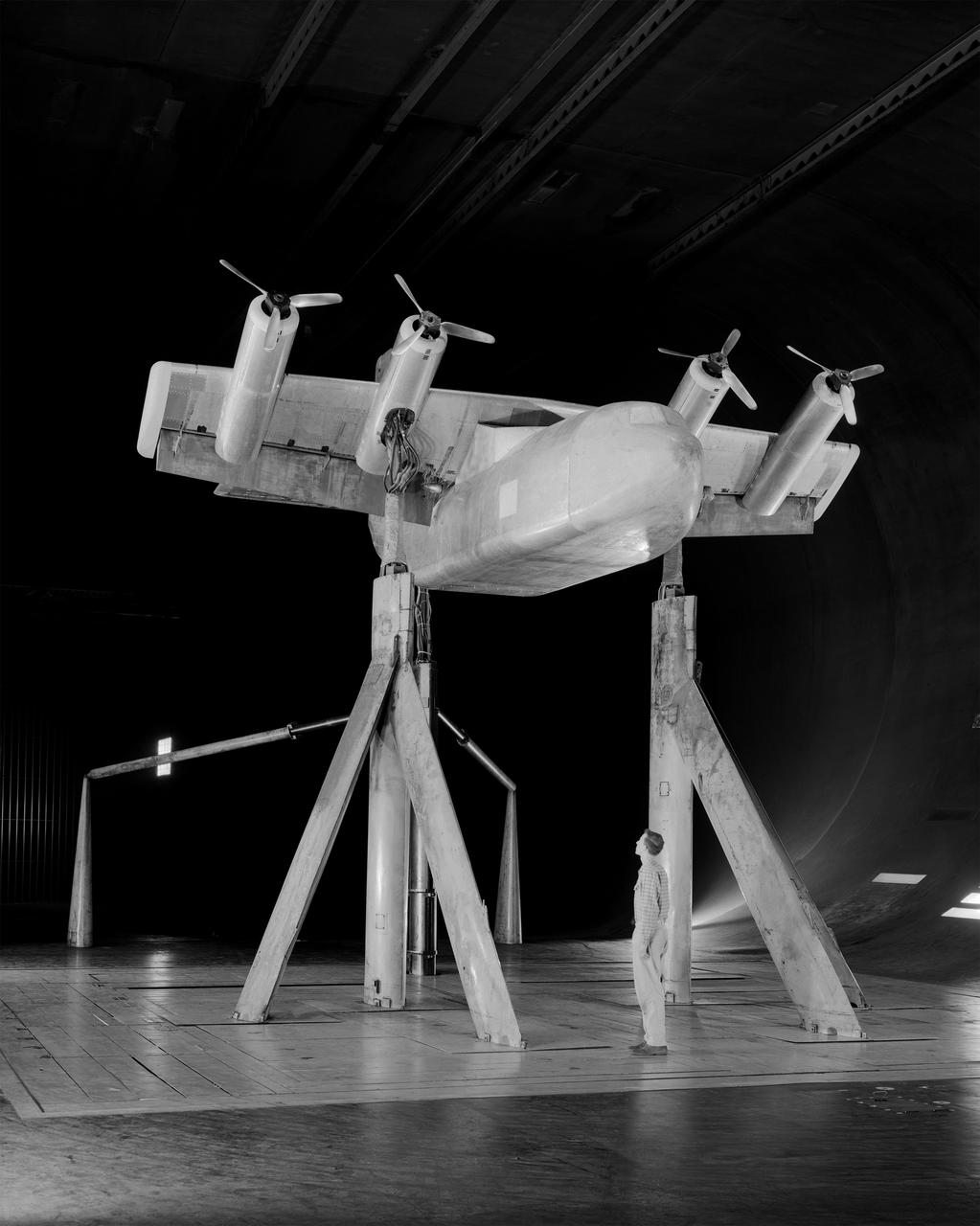
4 propeller Tilt Wing. Pictured with Tommy Wills wind tunnel mechanic in the 40x80 foot wind tunnel.
Technicians ready a single rotating propeller model in the 8x6 Supersonic Wind Tunnel
Test of Lockheed YC-130 Turbo-Propeller Installation in Ames 40x80 Foot Wind Tunnel. 3/4 front view from below.
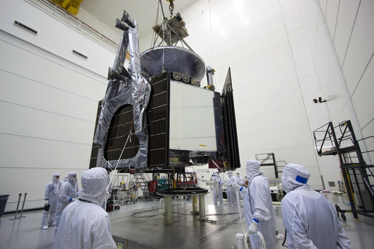
Technicians work to complete operations before propellant load occurs ahead of launch for NASA’s Europa Clipper spacecraft inside the Payload Hazardous Servicing Facility at the agency’s Kennedy Space Center in Florida on Tuesday, Sept. 11, 2024. Europa could have all the “ingredients” for life as we know it: water, organics, chemical energy, and stability. Europa Clipper’s launch period opens on October 10, 2024.
Technicians work to complete operations before propellant load occurs ahead of launch for NASA’s Europa Clipper spacecraft inside the Payload Hazardous Servicing Facility at the agency’s Kennedy Space Center in Florida on Tuesday, Sept. 11, 2024. Europa could have all the “ingredients” for life as we know it: water, organics, chemical energy, and stability. Europa Clipper’s launch period opens on October 10, 2024.
Technicians work to complete operations before propellant load occurs ahead of launch for NASA’s Europa Clipper spacecraft inside the Payload Hazardous Servicing Facility at the agency’s Kennedy Space Center in Florida on Tuesday, Sept. 11, 2024. Europa could have all the “ingredients” for life as we know it: water, organics, chemical energy, and stability. Europa Clipper’s launch period opens on October 10, 2024.
Technicians work to complete operations before propellant load occurs ahead of launch for NASA’s Europa Clipper spacecraft inside the Payload Hazardous Servicing Facility at the agency’s Kennedy Space Center in Florida on Tuesday, Sept. 11, 2024. Europa could have all the “ingredients” for life as we know it: water, organics, chemical energy, and stability. Europa Clipper’s launch period opens on October 10, 2024.
Technicians work to complete operations before propellant load occurs ahead of launch for NASA’s Europa Clipper spacecraft inside the Payload Hazardous Servicing Facility at the agency’s Kennedy Space Center in Florida on Tuesday, Sept. 11, 2024. Europa could have all the “ingredients” for life as we know it: water, organics, chemical energy, and stability. Europa Clipper’s launch period opens on October 10, 2024.
Technicians work to complete operations before propellant load occurs ahead of launch for NASA’s Europa Clipper spacecraft inside the Payload Hazardous Servicing Facility at the agency’s Kennedy Space Center in Florida on Tuesday, Sept. 11, 2024. Europa could have all the “ingredients” for life as we know it: water, organics, chemical energy, and stability. Europa Clipper’s launch period opens on October 10, 2024.
Technicians work to complete operations before propellant load occurs ahead of launch for NASA’s Europa Clipper spacecraft inside the Payload Hazardous Servicing Facility at the agency’s Kennedy Space Center in Florida on Tuesday, Sept. 11, 2024. Europa could have all the “ingredients” for life as we know it: water, organics, chemical energy, and stability. Europa Clipper’s launch period opens on October 10, 2024.
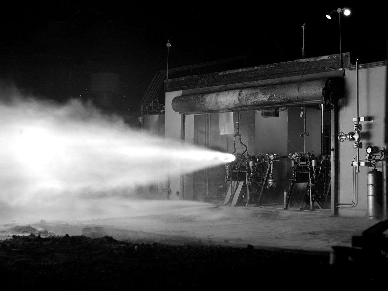
A rocket using high-energy propellant is fired from the Rocket Laboratory at the National Advisory Committee for Aeronautics (NACA) Lewis Flight Propulsion Laboratory. The Rocket Lab was a collection of ten one-story cinderblock test cells located behind earthen barriers at the western edge of the campus. The rocket engines tested there were comparatively small, but the Lewis researchers were able to study different configurations, combustion performance, and injectors and nozzle design. The rockets were generally mounted horizontally and fired, as seen in this photograph of Test Cell No. 22. A group of fuels researchers at Lewis refocused their efforts after World War II in order to explore high energy propellants, combustion, and cooling. Research in these three areas began in 1945 and continued through the 1960s. The group of rocket researches was not elevated to a division branch until 1952. The early NACA Lewis work led to the development of liquid hydrogen as a viable propellant in the late 1950s. Following the 1949 reorganization of the research divisions, the rocket group began working with high-energy propellants such as diborane, pentaborane, and hydrogen. The lightweight fuels offered high levels of energy but were difficult to handle and required large tanks. In late 1954, Lewis researchers studied the combustion characteristics of gaseous hydrogen in a turbojet combustor. Despite poor mixing of the fuel and air, it was found that the hydrogen yielded more than a 90-percent efficiency. Liquid hydrogen became the focus of Lewis researchers for the next 15 years.
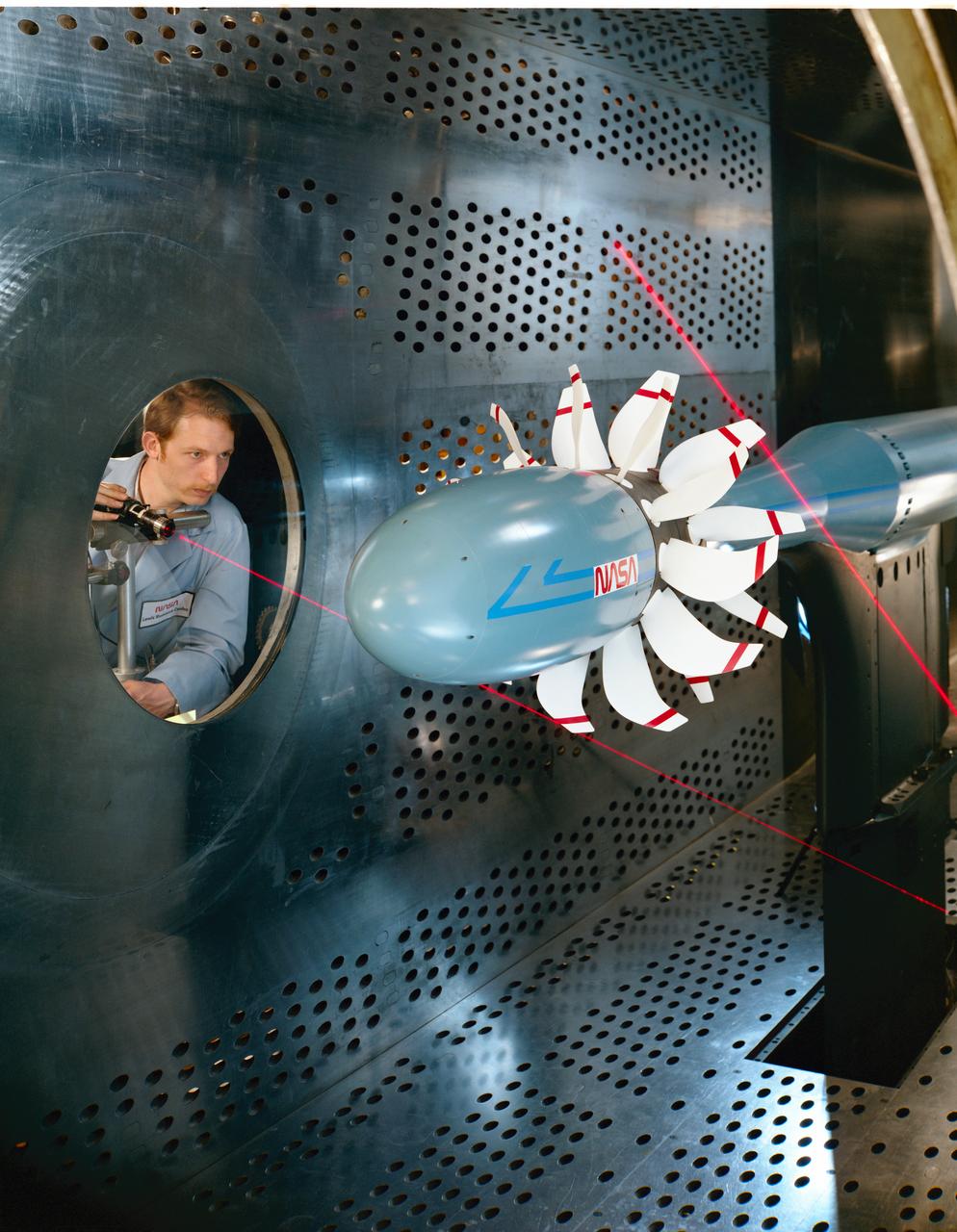
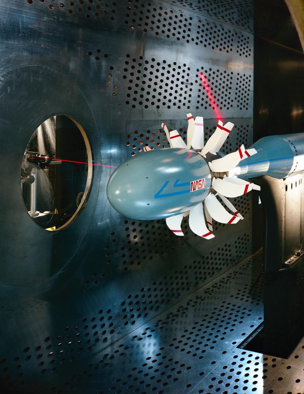
Laser based blade deflection measurement system on Counter Rotation Pusher Propeller model in 8x6 SWT (Supersonic Wind Tunnel)
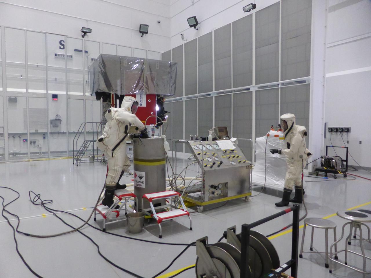
NASA’s IMAP (Interstellar Mapping and Acceleration Probe) observatory arrives at Building 2 where technicians will load 317 pounds (or 144 kilograms) of hydrazine into three tanks into the spacecraft at the Astrotech Space Operations Facility near NASA’s Kennedy Space Center in Florida on Tuesday, Aug. 12, 2025. IMAP will explore and map the boundaries of the heliosphere — a huge bubble created by the Sun’s wind that encapsulates our entire solar system — and study how the heliosphere interacts with the local galactic neighborhood beyond.
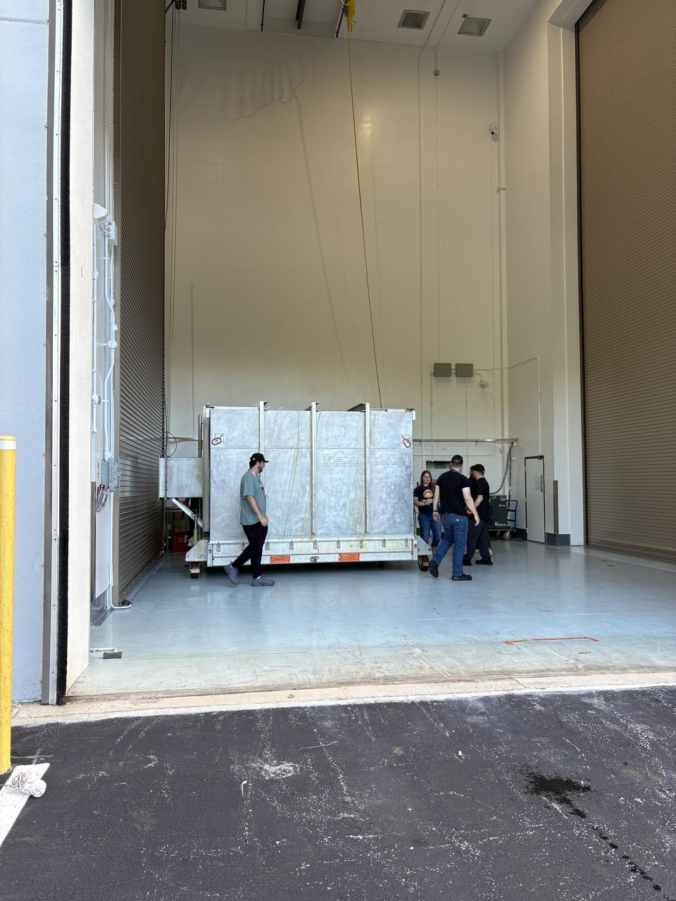
Technicians prepare to transport NASA’s IMAP (Interstellar Mapping and Acceleration Probe) observatory to Building 2 where they will load 317 pounds (or 144 kilograms) of hydrazine into three tanks into the spacecraft at the Astrotech Space Operations Facility near NASA’s Kennedy Space Center in Florida on Tuesday, Aug. 12, 2025. IMAP will explore and map the boundaries of the heliosphere — a huge bubble created by the Sun’s wind that encapsulates our entire solar system — and study how the heliosphere interacts with the local galactic neighborhood beyond.

Technicians transport NASA’s IMAP (Interstellar Mapping and Acceleration Probe) observatory to Building 2 where they will load 317 pounds (or 144 kilograms) of hydrazine into three tanks into the spacecraft at the Astrotech Space Operations Facility near NASA’s Kennedy Space Center in Florida on Tuesday, Aug. 12, 2025. IMAP will explore and map the boundaries of the heliosphere — a huge bubble created by the Sun’s wind that encapsulates our entire solar system — and study how the heliosphere interacts with the local galactic neighborhood beyond.
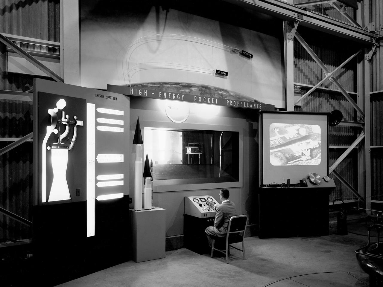
A researcher works a demonstration board in the Rocket Engine Test Facility during the 1957 Inspection of the National Advisory Committee for Aeronautics (NACA) Lewis Flight Propulsion Laboratory in Cleveland, Ohio. Representatives from the military, aeronautical industry, universities, and the press were invited to the laboratory to be briefed on the NACA’s latest research efforts and tour the test facilities. Over 1700 people visited the Lewis during the October 7-10, 1957 Inspection. The Soviet Union launched their first Sputnik satellite just days before on October 4. NACA Lewis had been involved in small rockets and propellants research since 1945, but the NACA leadership was wary of involving itself too deeply with the work since ballistics traditionally fell under the military’s purview. The Lewis research was performed by the High Temperature Combustion section in the Fuels and Lubricants Division in a series of small cinderblock test cells. The rocket group was expanded in 1952 and made several test runs in late 1954 using liquid hydrogen as a propellant. A larger test facility, the Rocket Engine Test Facility, was approved and became operational just in time for the Inspection.
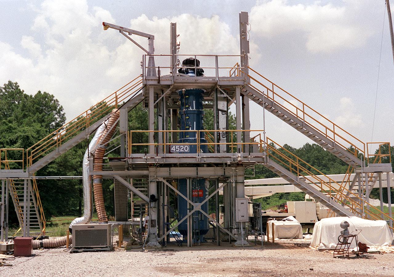
This photograph shows the Solid Propellant Test Article (SPTA) test stand with the Modified Nasa Motor (M-NASA) test article at the Marshall Space Flight Center (MSFC). The SPTA test stand, 12-feet wide by 12-feet long by 24-feet high, was built in 1989 to provide comparative performance data on nozzle and case insulation material and to verify thermostructural analysis models. A modified NASA 48-inch solid motor (M-NASA motor) with a 12-foot blast tube and 10-inch throat makes up the SPTA. The M-NASA motor is being used to evaluate solid rocket motor internal non-asbestos insulation materials, nozzle designs, materials, and new inspection techniques. New internal motor case instrumentation techniques are also being evaluated.
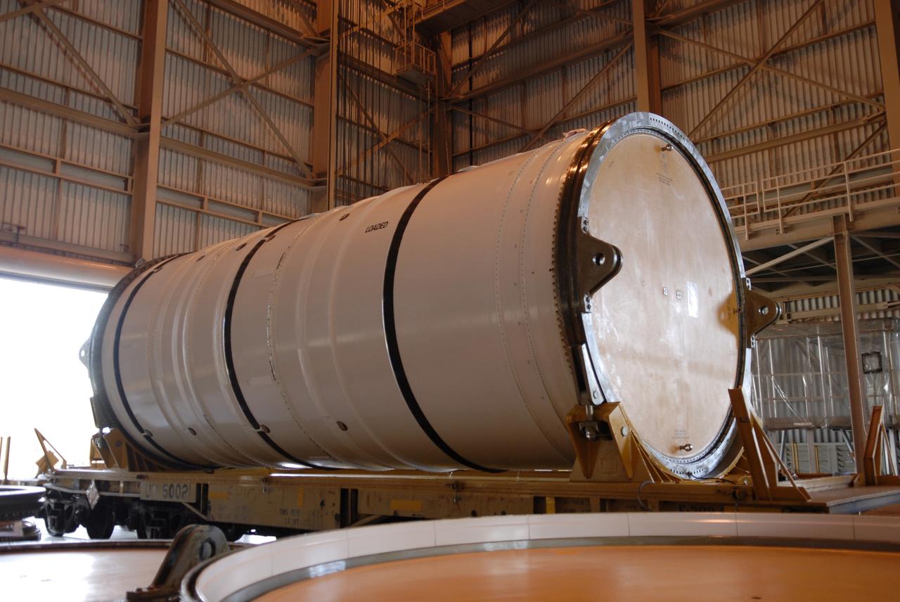
CAPE CANAVERAL, Fla. – In the Rotation, Processing and Surge Facility at NASA's Kennedy Space Center in Florida, the Ares I-X motor segment waits for inspection after removal of the shipping container. It is one of four reusable motor segments and nozzle exit cone shipped by the Ares I first-stage prime contractor Alliant Techsystems Inc. for final processing and integration in the facility. The booster used for the Ares I-X launch is being modified by adding new forward structures and a fifth segment simulator. The motor is the final hardware needed for the rocket's upcoming flight test this summer. The stacking operations are scheduled to begin in the Vehicle Assembly Building in April. Photo credit: NASA/Jim Grossmann
CAPE CANAVERAL, Fla. – In the Rotation, Processing and Surge Facility at NASA's Kennedy Space Center in Florida, the open end of the Ares I-X motor segment is seen without the end cover. It is one of four reusable motor segments and nozzle exit cone shipped by the Ares I first-stage prime contractor Alliant Techsystems Inc. for final processing and integration in the facility. The booster used for the Ares I-X launch is being modified by adding new forward structures and a fifth segment simulator. The motor is the final hardware needed for the rocket's upcoming flight test this summer. The stacking operations are scheduled to begin in the Vehicle Assembly Building in April. Photo credit: NASA/Jim Grossmann
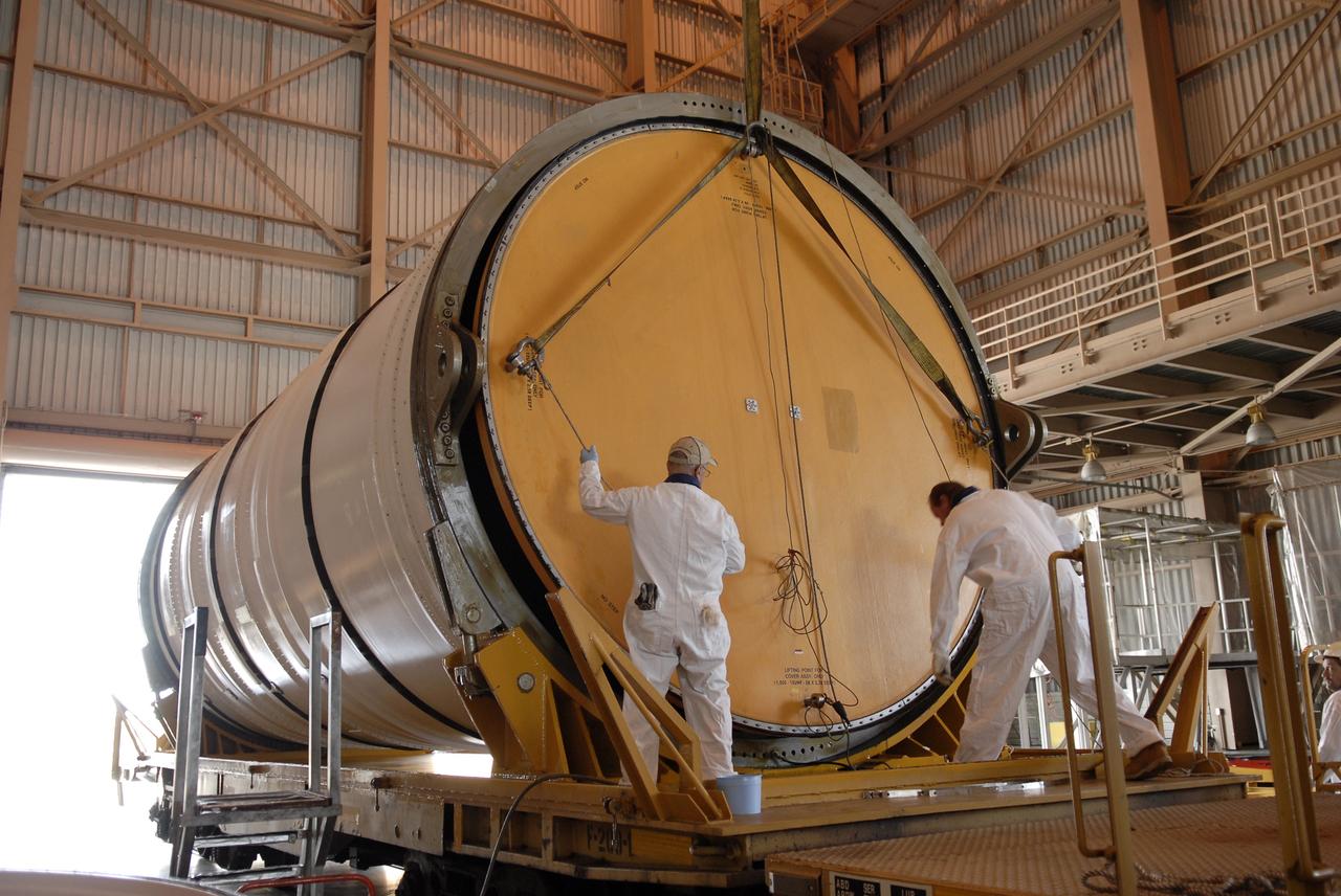
CAPE CANAVERAL, Fla. – In the Rotation, Processing and Surge Facility at NASA's Kennedy Space Center in Florida, technicians check the fit of the end cover on the Ares I-X motor segment. It is one of four reusable motor segments and nozzle exit cone shipped by the Ares I first-stage prime contractor Alliant Techsystems Inc. for final processing and integration in the facility. The booster used for the Ares I-X launch is being modified by adding new forward structures and a fifth segment simulator. The motor is the final hardware needed for the rocket's upcoming flight test this summer. The stacking operations are scheduled to begin in the Vehicle Assembly Building in April. Photo credit: NASA/Jim Grossmann
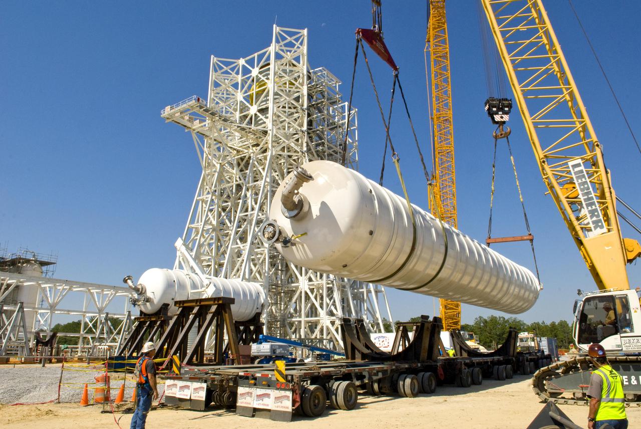
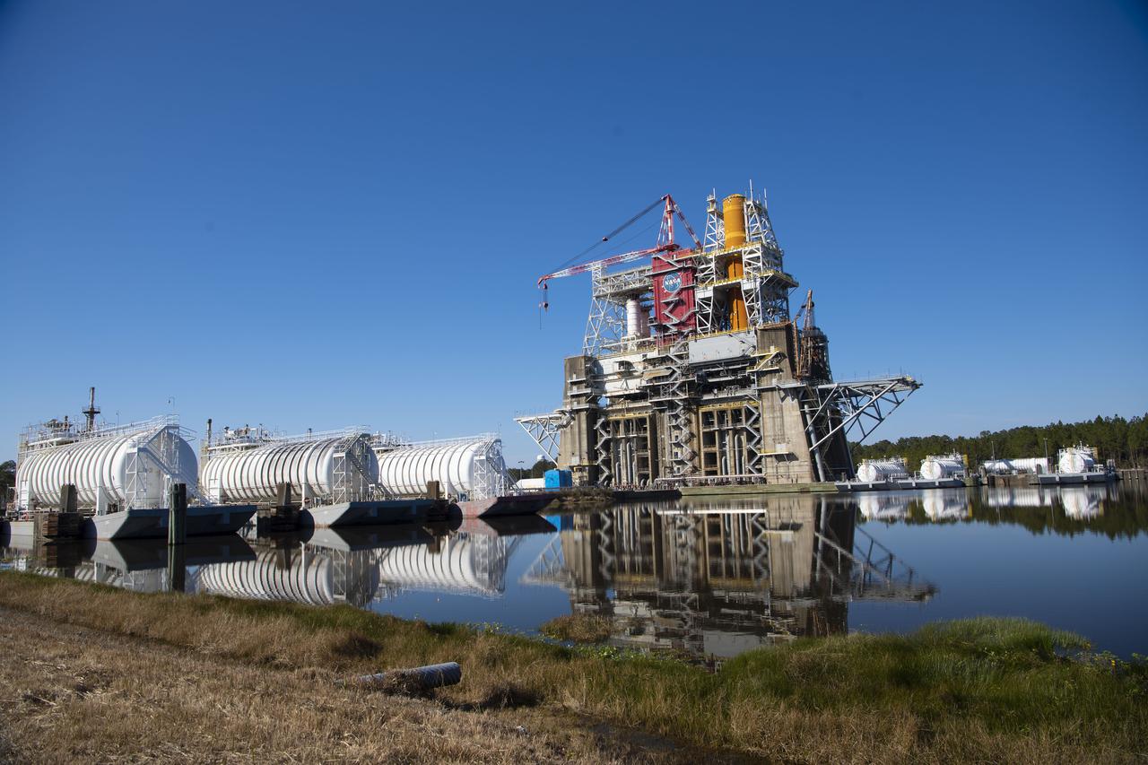
An 80,000-gallon liquid hydrogen tank is placed at the A-3 Test Stand construction site on Sept. 24, 2010. The tank will provide propellant for tests of next-generation rocket engines at the stand. It will be placed upright on top of the stand, helping to increase the overall height to 300 feet. Once completed, the A-3 Test Stand will enable operators to test rocket engines at simulated altitudes of up to 100,000 feet. The A-3 stand is the first large rocket engine test structure to be built at Stennis Space Center since the 1960s.
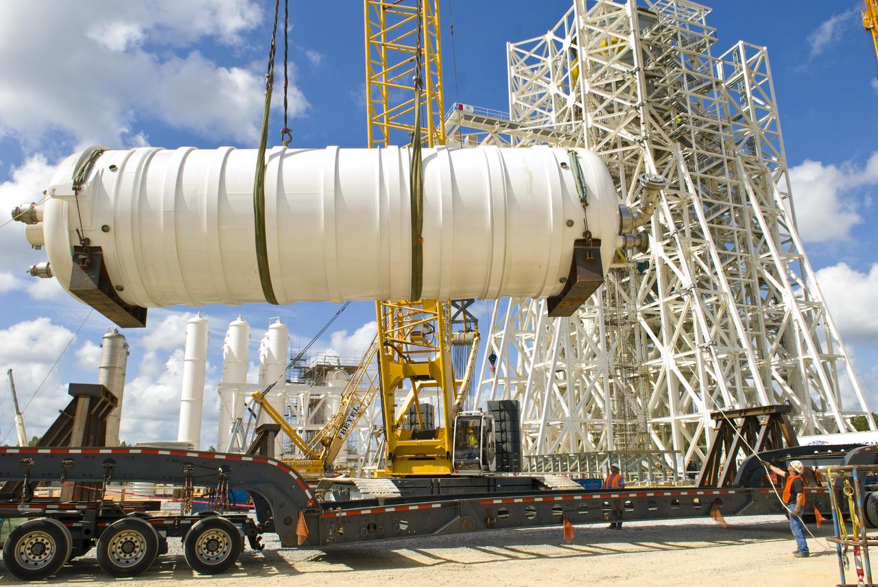
A 35,000-gallon liquid oxygen tank is placed at the A-3 Test Stand construction site on Sept. 24, 2010. The tank will provide propellant for tests of next-generation rocket engines at the stand. It will be placed upright on top of the stand, helping to increase the overall height to 300 feet. Once completed, the A-3 Test Stand will enable operators to test rocket engines at simulated altitudes of up to 100,000 feet. The A-3 stand is the first large rocket engine test structure to be built at Stennis Space Center since the 1960s.

Photo shows how the Space Launch Sysetm (SLS) rocket liquid oxygen tank failed during a structural qualification test at NASA’s Marshall Space Flight Center in Huntsville, Alabama. The photos show both the water flowing from the tank as it ruptured and the resultant tear left in the tank when it buckled during the test. Engineers pushed the liquid oxygen structural test article to the limits on purpose. The tank is a test article that is identical to tanks that are part of the SLS core stage that will produce 2 million pounds of thrust to help launch the rocket on the Artemis missions to the Moon. During the test, hydraulic cylinders were then calibrated and positioned along the tank to apply millions of pounds of crippling force from all sides while engineers measured and recorded the effects of the launch and flight forces. For the test, water used to simulate the liquid oxygen flows out of the tank after it ruptures. The structural test campaign was conducted on the rocket to ensure the SLS rocket’s structure can endure the rigors of launch and safely send astronauts to the Moon on the Artemis missions. For more information: https://www.nasa.gov/exploration/systems/sls/nasa-completes-artemis-sls-structural-testing-campaign.html

Photo shows how the Space Launch Sysetm (SLS) rocket liquid oxygen tank failed during a structural qualification test at NASA’s Marshall Space Flight Center in Huntsville, Alabama. The photos show both the water flowing from the tank as it ruptured and the resultant tear left in the tank when it buckled during the test. Engineers pushed the liquid oxygen structural test article to the limits on purpose. The tank is a test article that is identical to tanks that are part of the SLS core stage that will produce 2 million pounds of thrust to help launch the rocket on the Artemis missions to the Moon. During the test, hydraulic cylinders were then calibrated and positioned along the tank to apply millions of pounds of crippling force from all sides while engineers measured and recorded the effects of the launch and flight forces. For the test, water used to simulate the liquid oxygen flows out of the tank after it ruptures. The structural test campaign was conducted on the rocket to ensure the SLS rocket’s structure can endure the rigors of launch and safely send astronauts to the Moon on the Artemis missions. For more information: https://www.nasa.gov/exploration/systems/sls/nasa-completes-artemis-sls-structural-testing-campaign.html

Photo shows how the Space Launch Sysetm (SLS) rocket liquid oxygen tank failed during a structural qualification test at NASA’s Marshall Space Flight Center in Huntsville, Alabama. The photos show both the water flowing from the tank as it ruptured and the resultant tear left in the tank when it buckled during the test. Engineers pushed the liquid oxygen structural test article to the limits on purpose. The tank is a test article that is identical to tanks that are part of the SLS core stage that will produce 2 million pounds of thrust to help launch the rocket on the Artemis missions to the Moon. During the test, hydraulic cylinders were then calibrated and positioned along the tank to apply millions of pounds of crippling force from all sides while engineers measured and recorded the effects of the launch and flight forces. For the test, water used to simulate the liquid oxygen flows out of the tank after it ruptures. The structural test campaign was conducted on the rocket to ensure the SLS rocket’s structure can endure the rigors of launch and safely send astronauts to the Moon on the Artemis missions. For more information: https://www.nasa.gov/exploration/systems/sls/nasa-completes-artemis-sls-structural-testing-campaign.html
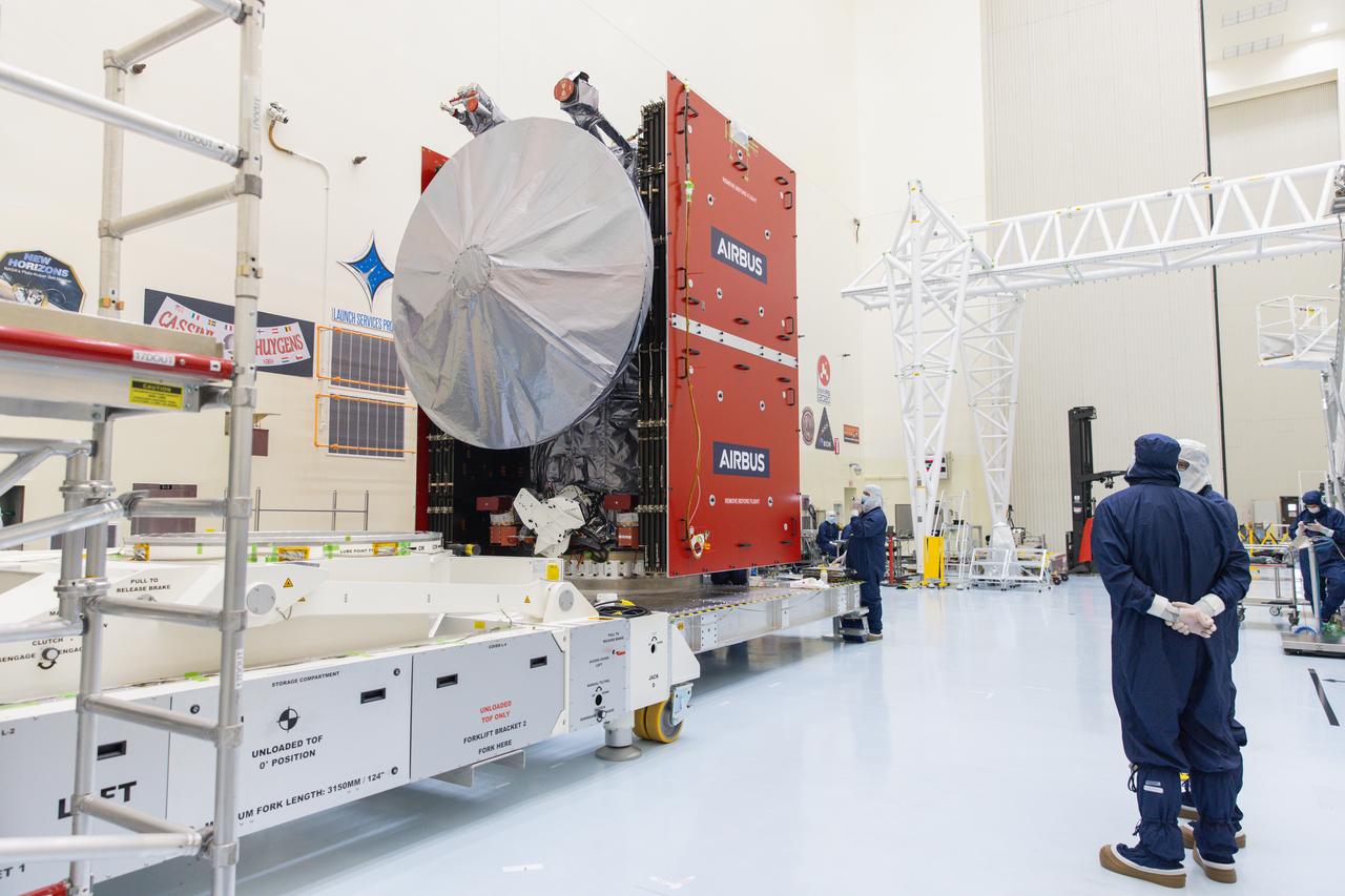
The Solar Orbiter spacecraft is transferred between buildings as it undergoes prelaunch processing at the Astrotech Space Operations facility in Titusville, Florida. Solar Orbiter aims to study the Sun, its outer atmosphere and solar wind, and will provide the first images of the Sun’s poles. Solar Orbiter is a space mission of international collaboration between ESA (European Space Agency) and NASA. The spacecraft has been developed by Airbus. NASA’s Launch Services Program based at Kennedy Space Center in Florida is managing the launch. Liftoff is scheduled for Feb. 5, 2020, from Cape Canaveral Air Force Station aboard a United Launch Alliance Atlas V rocket.
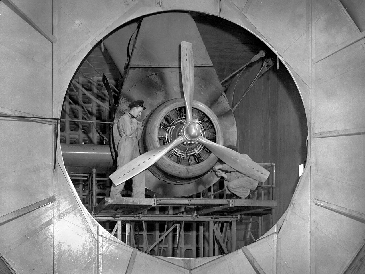
A Wright Aeronautical R–2600 Cyclone piston engine installed in the Engine Propeller Research Building, or Prop House, at the National Advisory Committee for Aeronautics (NACA) Aircraft Engine Research Laboratory. The R–2600 was among the most powerful engines that emerged during World War II. The engine, which was developed for commercial applications in 1939, was used to power the North American B–25 bomber and several other midsize military aircraft. The higher altitudes required by the military caused problems with the engine's cooling and fuel systems. The military requested that the Aircraft Engine Research Laboratory analyze the performance of the R–2600, improve its cooling system, and reduce engine knock. The NACA researchers subjected the engine to numerous tests in its Prop House. The R–2600 was the subject of the laboratory's first technical report, which was written by members of the Fuels and Lubricants Division. The Prop House contained soundproof test cells in which piston engines and propellers were mounted and operated at high powers. Electrically driven fans drew air through ducts to create a stream of cooling air over the engines. Researchers tested the performance of fuels, turbochargers, water-injection and cooling systems here during World War II. The facility was also investigated a captured German V–I buzz bomb during the war.

NASA John C. Stennis Space Center employee Dustan Ladner (left) assists tanker driver David Velasco in transferring RP-1 fuel to a 20,000-gallon underground tank at the E-1 Test Stand during a March 30 delivery. The rocket propellant will be used for testing Aerojet AJ26 rocket engines beginning this summer. Stennis is testing the engines for Orbital Sciences Corporation, which has partnered with NASA to provide eight supply missions to the International Space Station through 2015. The partnership is part of NASA's Commercial Orbital Transportation Services initiative to work closer with companies to provide commercial space transport once the space shuttle is retired later this year.
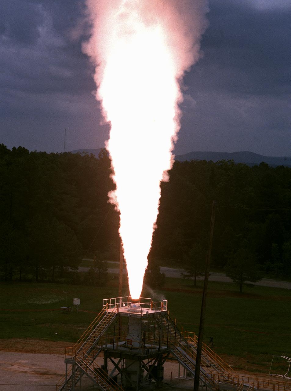
The Marshall Space Flight Center (MSFC) engineers test fired a 26-foot long, 100,000-pound-thrust solid rocket motor for 30 seconds at the MSFC east test area, the first test firing of the Modified NASA Motor (M-NASA Motor). The M-NASA Motor was fired in a newly constructed stand. The motor is 48-inches in diameter and was loaded with two propellant cartridges weighing a total of approximately 12,000 pounds. The purpose of the test was to learn more about solid rocket motor insulation and nozzle materials and to provide young engineers additional hands-on expertise in solid rocket motor technology. The test is a part of NASA's Solid Propulsion Integrity Program, that is to provide NASA engineers with the techniques, engineering tools, and computer programs to be able to better design, build, and verify solid rocket motors.
Engineers gather aerodynamic data on the integrated experimental testbed without the electric motor propellers.
An exposed, side view of NASA Juno spacecraft during its assembly features three of the spacecraft spherical propellant tanks.
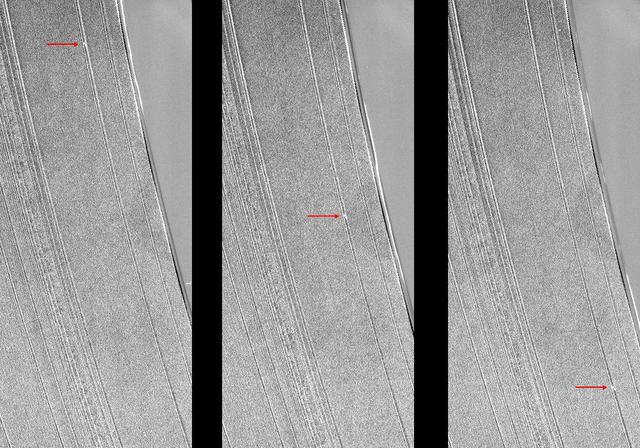
These three images from NASA Cassini spacecraft show a propeller-shaped structure created by an unseen moon in Saturn A ring.
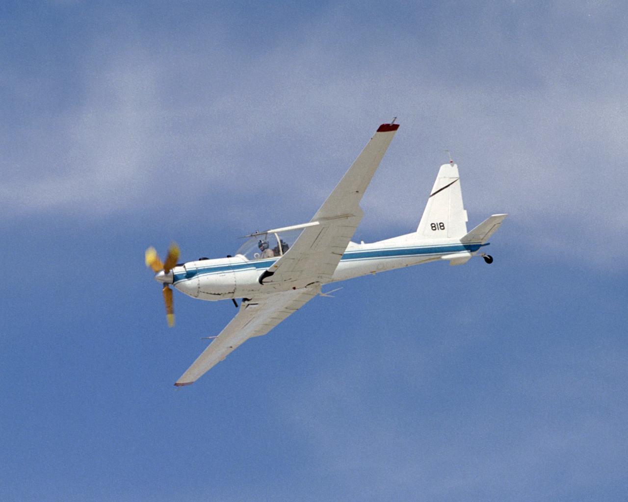
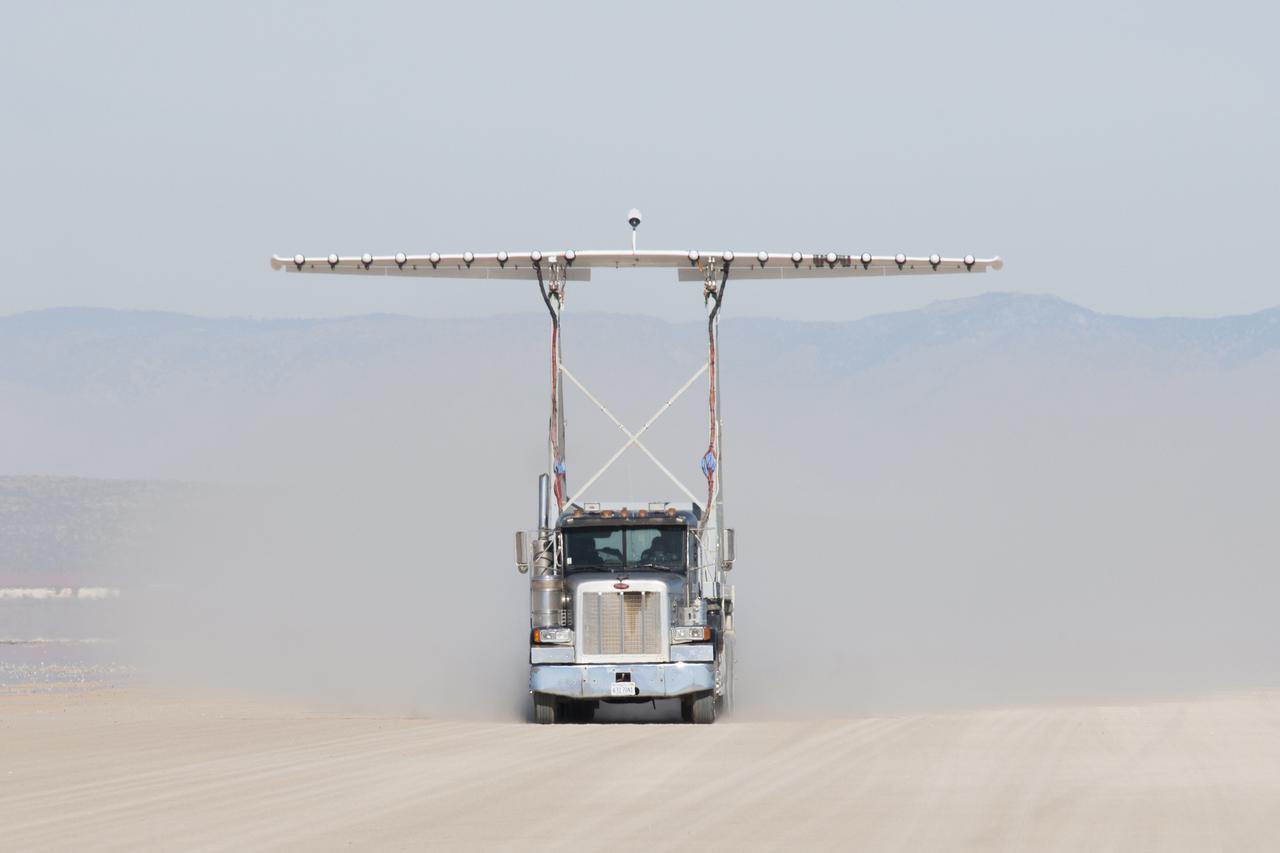
The slow-speed wooden propeller and long wings are evident as NASA's YO-3A acoustics research aircraft performs a low-level flyover at Edwards Air Force Base.

KENNEDY SPACE CENTER, FLA. - Jeff Thon, an SRB mechanic with United Space Alliance, tests a technique for vertical solid rocket booster propellant grain inspection. The inspection of segments is required as part of safety analysis.
Propellant barges are docked at the B-2 Test Stand at NASA’s Stennis Space Center near Bay St. Louis, Mississippi, prior the hot fire test of the core stage for the agency’s Space Launch System rocket. The hot fire test Jan. 16, 2021 of the stage’s four RS-25 engines generated a combined 1.6 million pounds of thrust, just as will occur during an actual launch. The hot fire is the final test of the Green Run test series, a comprehensive assessment of the SLS core stage prior to launching the Artemis I mission to the Moon.
Technicians use an overhead crane to lower NASA Juno spacecraft onto a fueling stand where the spacecraft will be loaded with the propellant necessary for its mission to Jupiter.
The propeller-shaped white dashes near the bottom of NASA Cassini spacecraft image reveal the location of a small moonlet embedded in Saturn A ring.
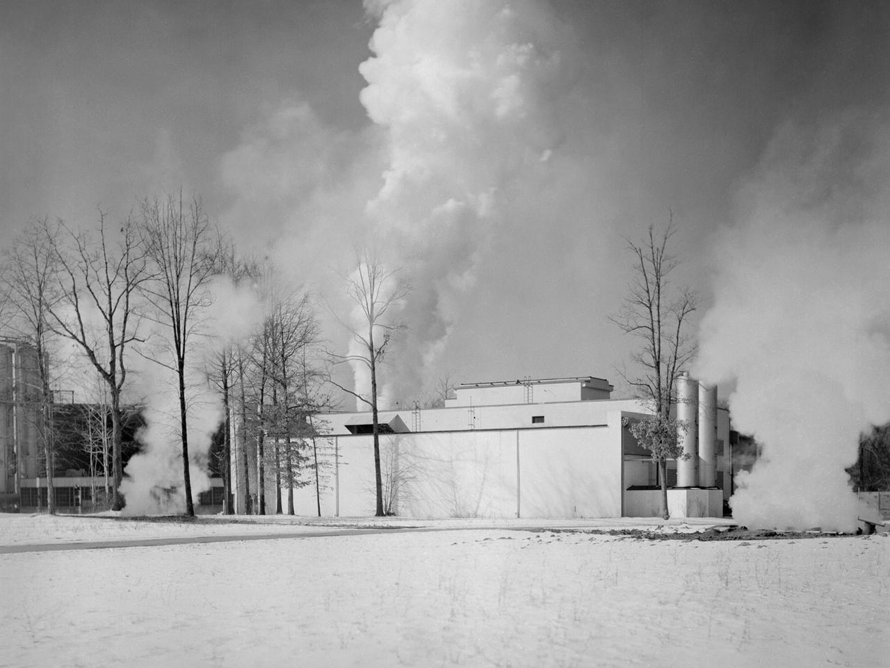
The Engine Propeller Research Building, referred to as the Prop House, emits steam from its acoustic silencers at the National Advisory Committee for Aeronautics (NACA) Lewis Flight Propulsion Laboratory. In 1942 the Prop House became the first completed test facility at the new NACA laboratory in Cleveland, Ohio. It contained four test cells designed to study large reciprocating engines. After World War II, the facility was modified to study turbojet engines. Two of the test cells were divided into smaller test chambers, resulting in a total of six engine stands. During this period the NACA Lewis Materials and Thermodynamics Division used four of the test cells to investigate jet engines constructed with alloys and other high temperature materials. The researchers operated the engines at higher temperatures to study stress, fatigue, rupture, and thermal shock. The Compressor and Turbine Division utilized another test cell to study a NACA-designed compressor installed on a full-scale engine. This design sought to increase engine thrust by increasing its airflow capacity. The higher stage pressure ratio resulted in a reduction of the number of required compressor stages. The last test cell was used at the time by the Engine Research Division to study the effect of high inlet densities on a jet engine. Within a couple years of this photograph the Prop House was significantly altered again. By 1960 the facility was renamed the Electric Propulsion Research Building to better describe its new role in electric propulsion.
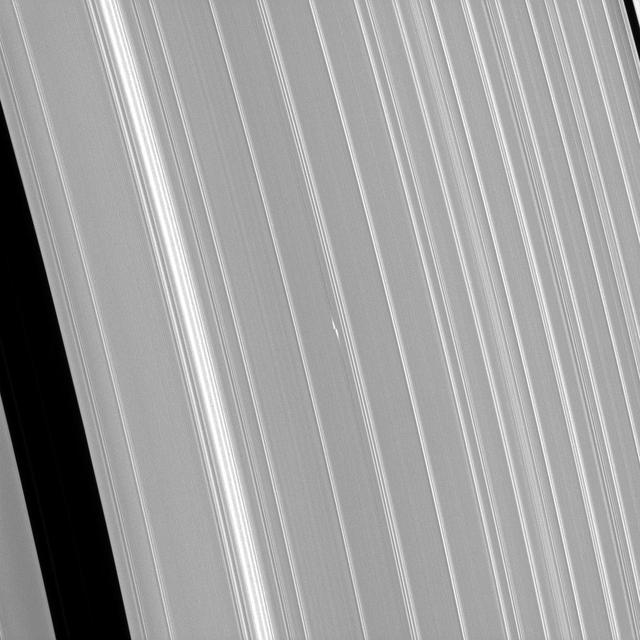
What appears as a pair of bright dashes at the center of this image is one of the features rings scientists have dubbed "propellers." This particular propeller, named Bleriot, marks the presence of a body that is much larger than the particles that surround it, yet too small to clear out a complete gap in the rings (like Pan and Daphnis) and become a moon in its own right. Although the moonlet at the core of the propeller is itself too small to see, the disturbances in the rings caused by its gravity betray its presence. Cassini scientists have been tracking propeller features like this one for years in order to learn how their orbits change over time. From this, they hope to gain insight into how forming planets migrate in the disks in which they form. This view looks toward the sunlit side of the rings from about 59 degrees above the ring plane. The image was taken in visible light with the Cassini spacecraft narrow-angle camera on Jan. 9, 2017. The view was acquired at a distance of approximately 223,000 miles (359,000 kilometers) from Saturn and at a Sun-Saturn-spacecraft, or phase, angle of 73 degrees. Image scale is 1.2 miles (2 kilometers) per pixel. http://photojournal.jpl.nasa.gov/catalog/PIA20525
4 propeller model with rotating cylinder flap. Propellers running. 3/4 front view. DAVE JONES (PROPS TURNING)
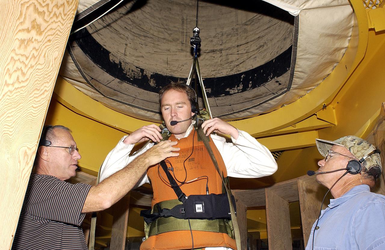
KENNEDY SPACE CENTER, FLA. - Jeff Thon, an SRB mechanic with United Space Alliance, is fitted with a harness to test a vertical solid rocket booster propellant grain inspection technique. Thon will be lowered inside a mockup of two segments of the SRBs. The inspection of segments is required as part of safety analysis.
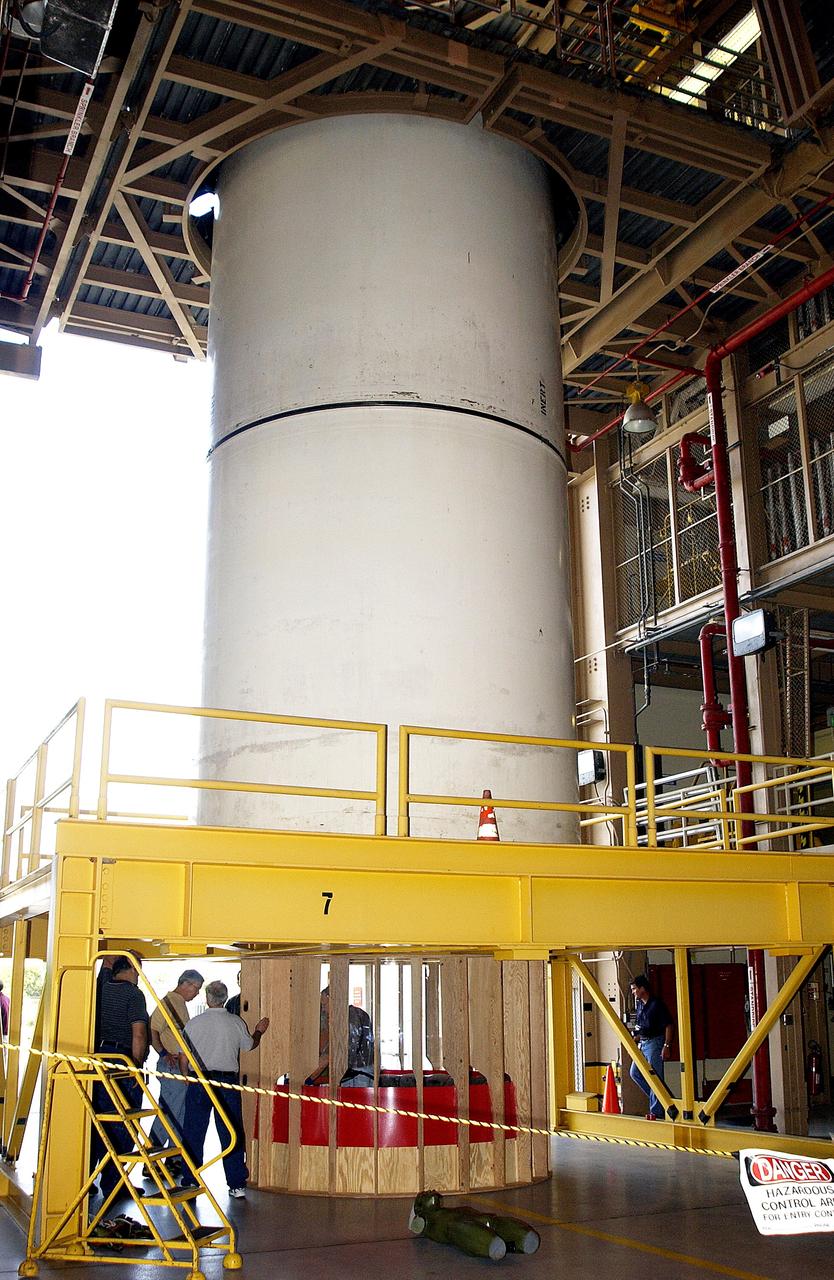
KENNEDY SPACE CENTER, FLA. - At the Rotation, Processing and Surge Facility stand a mockup of two segments of a solid rocket booster (SRB) being used to test the feasibility of a vertical SRB propellant grain inspection, required as part of safety analysis.
KENNEDY SPACE CENTER, FLA. - Workers in the Orbiter Processing Facility insert the liquid oxygen feedline for the 17-inch disconnect in the orbiter Discovery. The 17-inch liquid oxygen and liquid hydrogen disconnects provide the propellant feed interface from the external tank to the orbiter main propulsion system and the three Shuttle main engines.
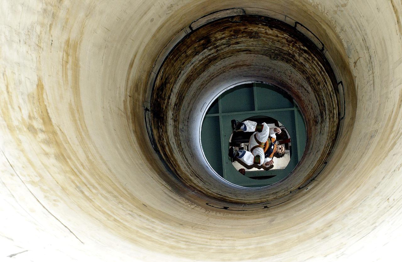
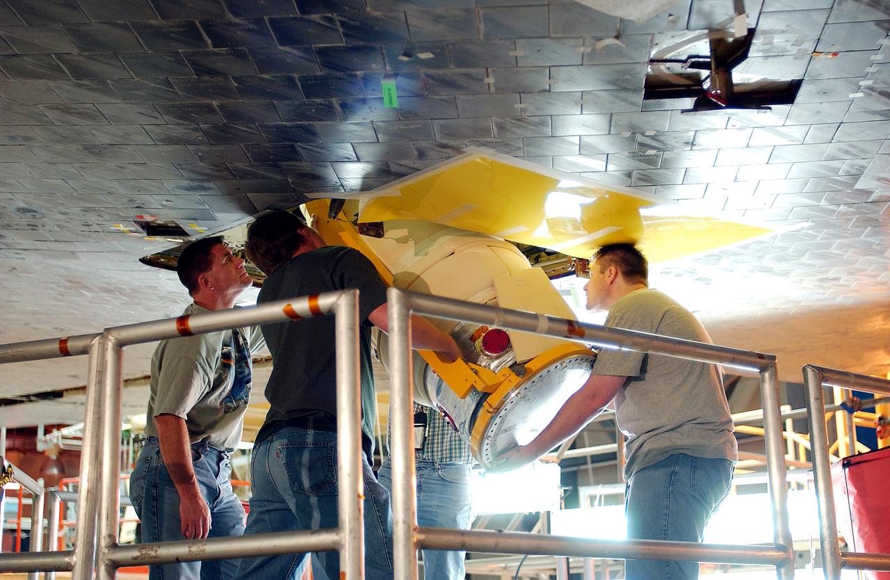
KENNEDY SPACE CENTER, FLA. - Seen from below and through a solid rocket booster segment mockup, Jeff Thon, an SRB mechanic with United Space Alliance, tests the feasibility of a vertical solid rocket booster propellant grain inspection technique. The inspection of segments is required as part of safety analysis.
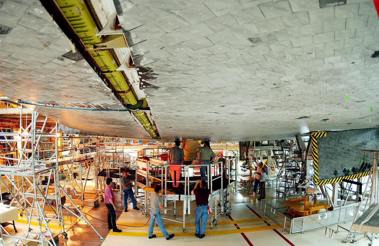
KENNEDY SPACE CENTER, FLA. - Workers in the Orbiter Processing Facility oversee installation of the liquid oxygen feedline for the 17-inch disconnect on the orbiter Discovery. The 17-inch liquid oxygen and liquid hydrogen disconnects provide the propellant feed interface from the external tank to the orbiter main propulsion system and the three Shuttle main engines.
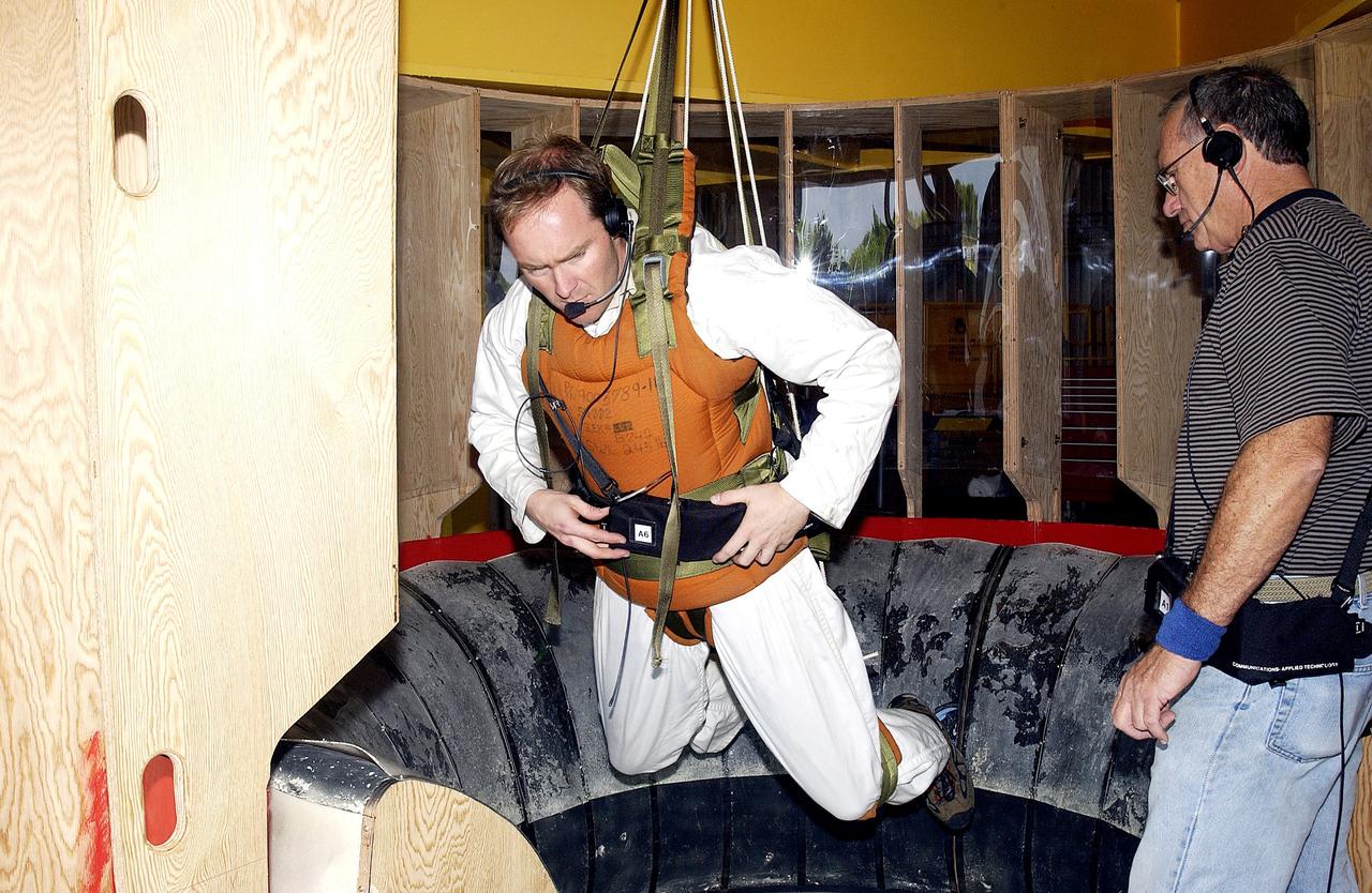
KENNEDY SPACE CENTER, FLA. - Jeff Thon, an SRB mechanic with United Space Alliance, is fitted with a harness to test a vertical solid rocket booster propellant grain inspection technique. Thon will be lowered inside a mockup of two segments of the SRBs. The inspection of segments is required as part of safety analysis.