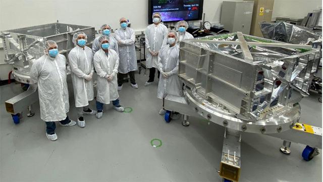
Fundamental Study of a boundary layer ingesting (BLI) propulsion model
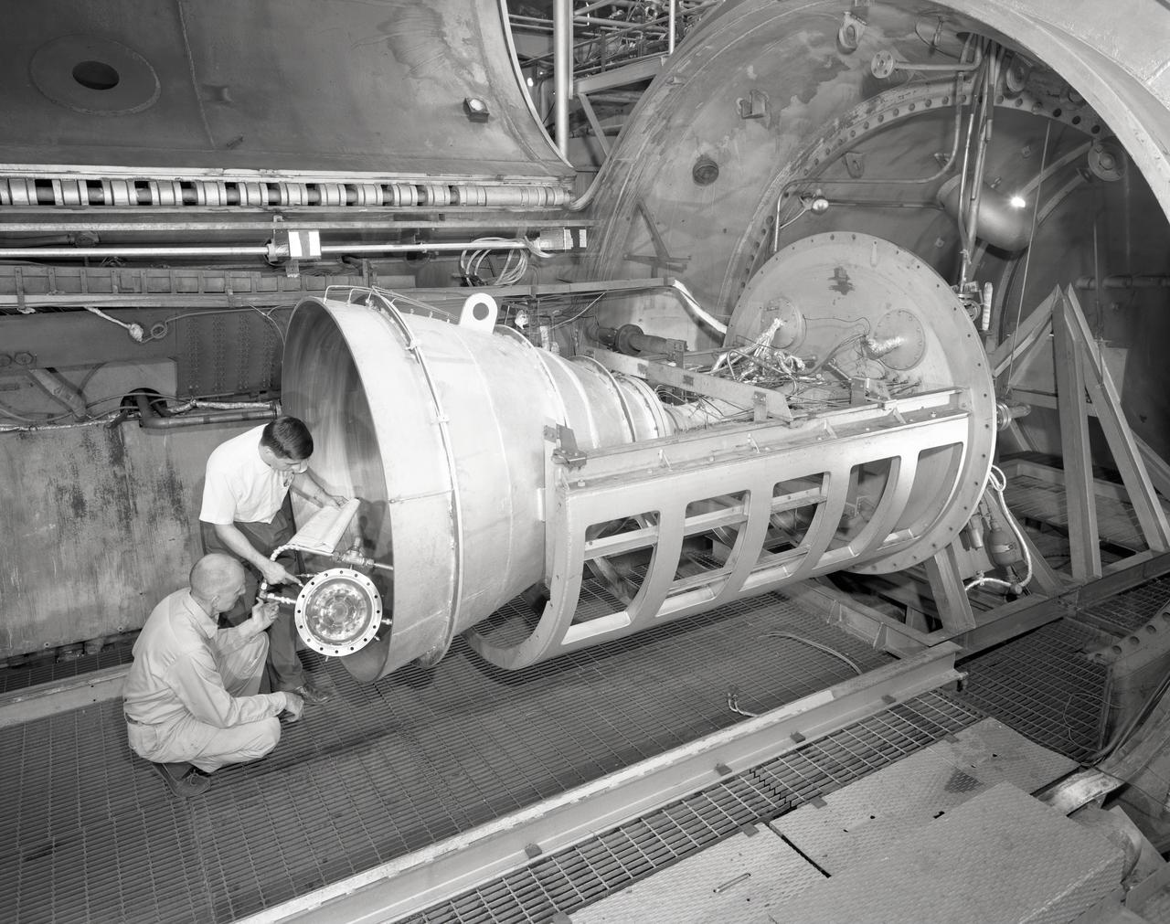
Apollo Contour Engine Model being tested in the NASA Lewis Research Center, Propulsion Systems Laboratory, PSL
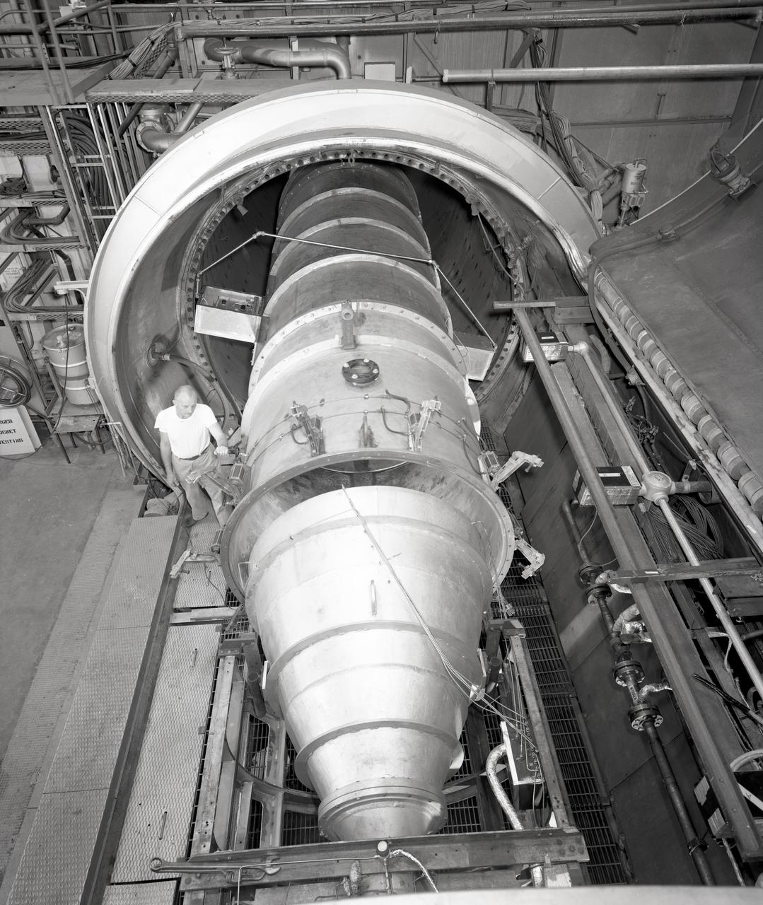
Apollo Contour Engine Model being tested in the NASA Lewis Research Center, Propulsion Systems Laboratory, PSL
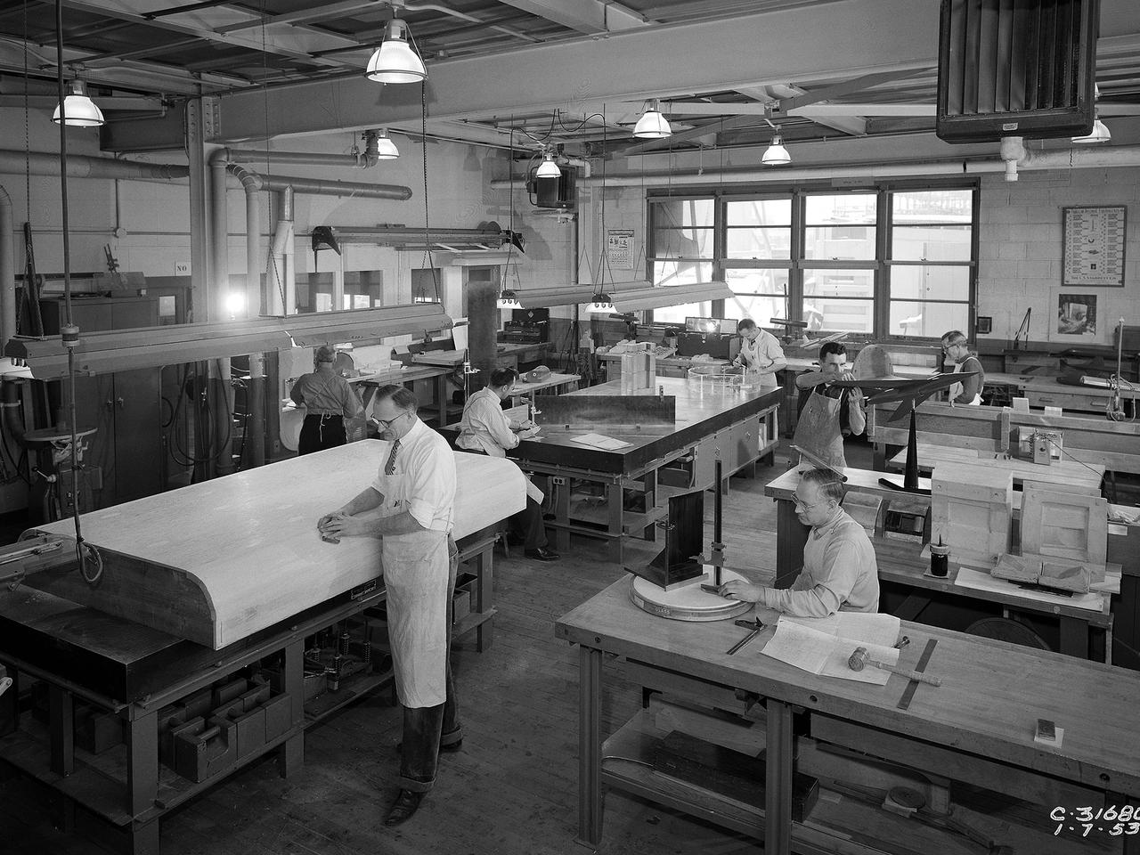
Craftsmen work in the wood model shop at the National Advisory Committee for Aeronautics (NACA) Lewis Flight Propulsion Laboratory. The Fabrication Division created almost all of the equipment and models used at the laboratory. The Fabrication Shop building contained a number of specialized shops in the 1940s and 1950s. These included a Machine Shop, Sheet Metal Shop, Wood Model and Pattern Shop, Instrument Shop, Thermocouple Shop, Heat Treating Shop, Metallurgical Laboratory, and Fabrication Office. The Wood Model and Pattern Shop created everything from control panels and cabinets to aircraft models molds for sheet metal work.
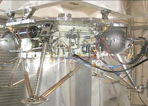
This video shows the propulsion system on an engineering model of NASA Phoenix Mars Lander being successfully tested.

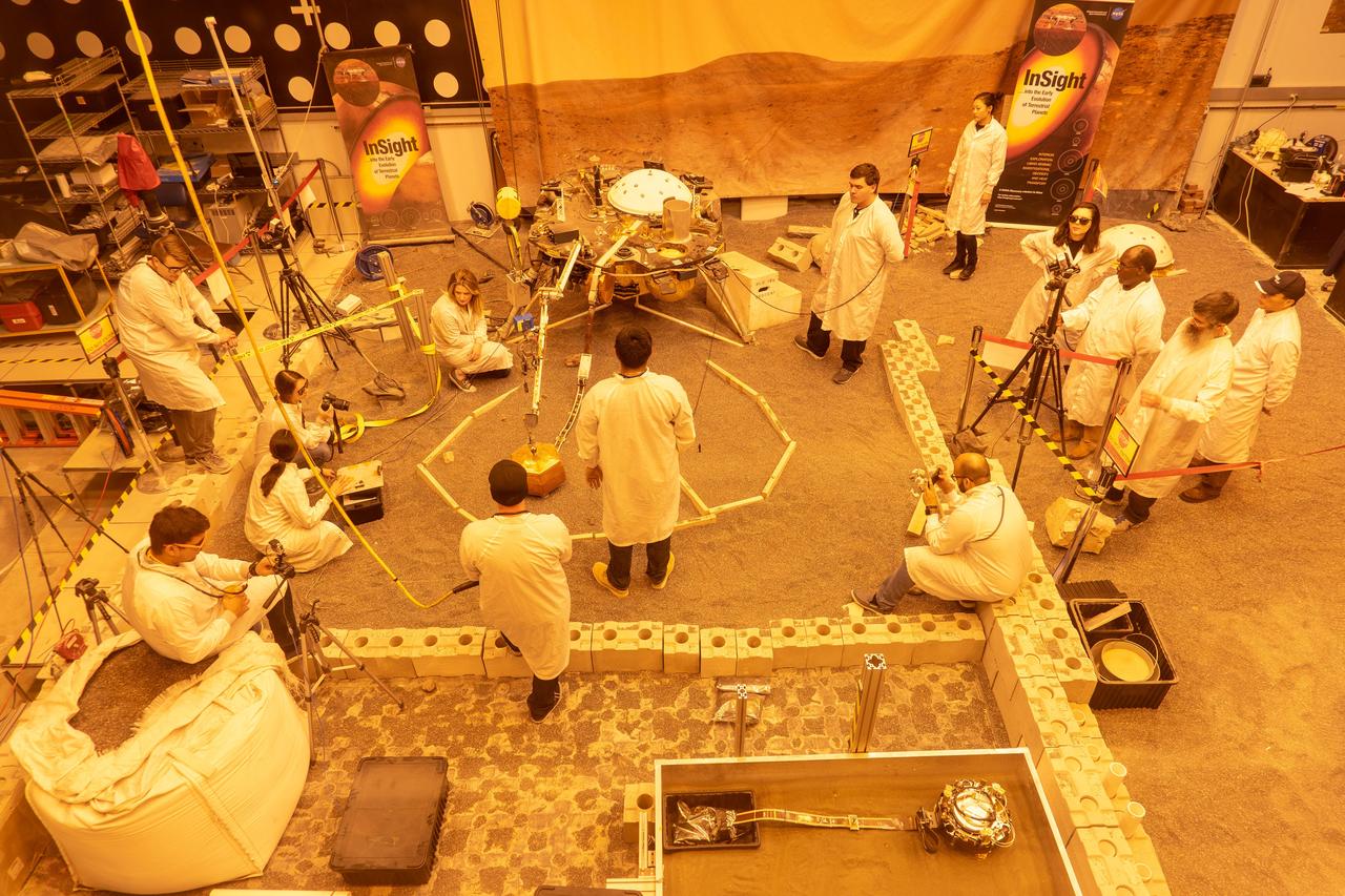
Journalist Mika McKinnon takes notes during a Mars InSight post-landing press conference while wearing a small model of the lander in her hair, Monday, Nov. 26, 2018 at NASA's Jet Propulsion Laboratory in Pasadena, California. InSight, short for Interior Exploration using Seismic Investigations, Geodesy and Heat Transport, is a Mars lander designed to study the "inner space" of Mars: its crust, mantle, and core. Photo Credit: (NASA/Bill Ingalls)
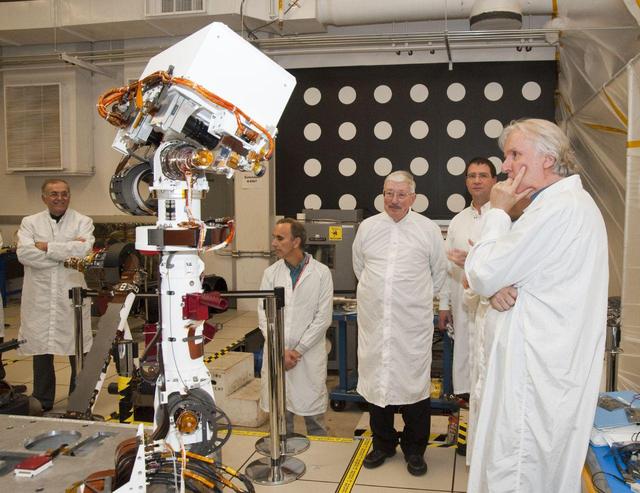
A group of members from the Jet Propulsion Laboratory watch the motions of an engineering model of the camera mast for NASA Mars rover Curiosity on March 5, 2010.
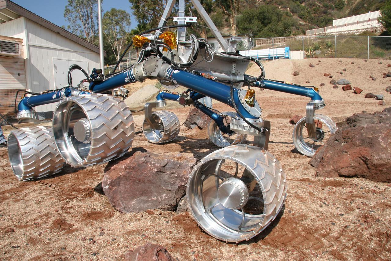
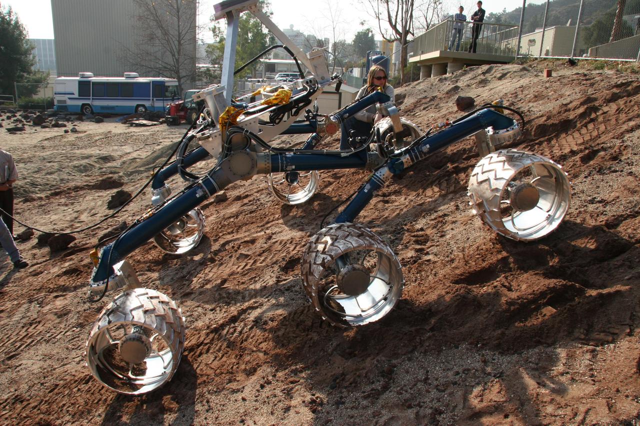
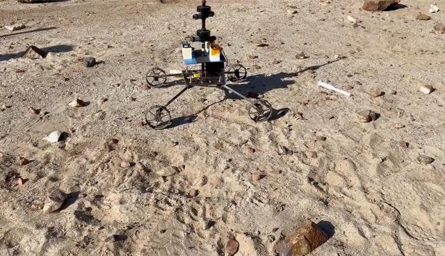
Scarecrow, a mobility-testing model for NASA Mars Science Laboratory, easily traverses large rocks in the Mars Yard testing area at NASA Jet Propulsion Laboratory.
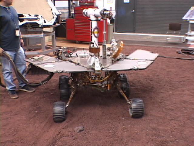
This picture shows a model of NASA Mars Exploration Rover Spirit being tested for performance on five wheels at NASA Jet Propulsion Laboratory.
An engineering model for NASA Mars Science Laboratory makes its way up a hill in the Mars Yard testing area at NASA Jet Propulsion Laboratory.
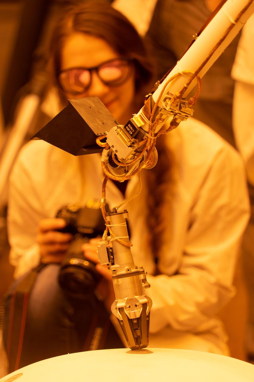
Engineer Marleen Sundgaard watches as a test version of NASA's Mars InSight lander grasps a model of the spacecraft's seismometer. This work was done at NASA's Jet Propulsion Laboratory in Pasadena, California. https://photojournal.jpl.nasa.gov/catalog/PIA22952
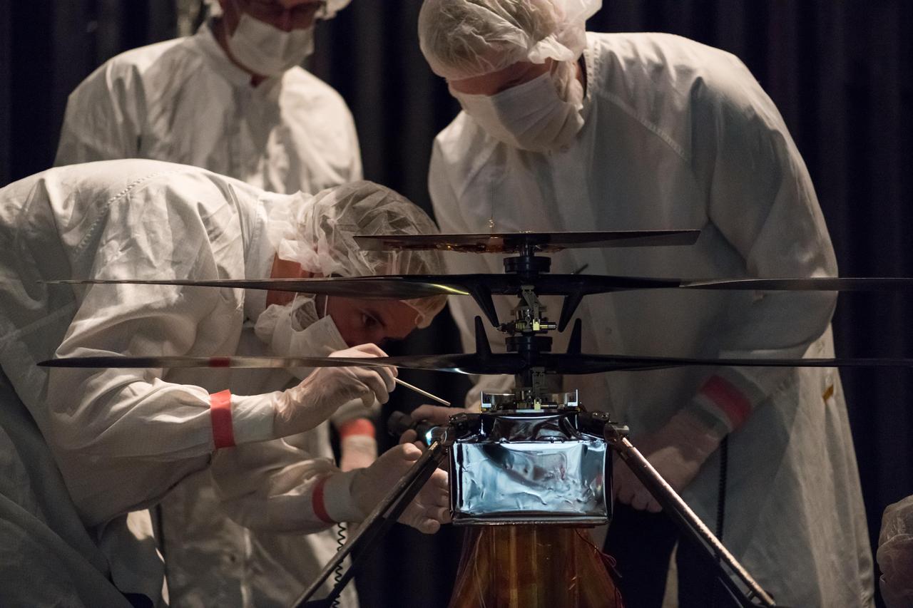
NASA Mars Helicopter team members work the flight model (the vehicle going to Mars) in the Space Simulator, a 25-foot-wide (7.62-meter-wide) vacuum chamber, at NASA's Jet Propulsion Laboratory in Pasadena, California. The image was taken on Feb. 1, 2019. https://photojournal.jpl.nasa.gov/catalog/PIA23152
ForeSight, a fully functional, full-size model of NASA's InSight lander, practices deploying a model of the lander's Wind and Thermal Shield while engineers Phil Bailey (left) and Jaime Singer (center) look on. The Wind and Thermal Shield protects InSight's seismometer. This testing was done at NASA's Jet Propulsion Laboratory in Pasadena, California. Bailey is wearing sunglasses to block the bright yellow lights in the test space, which mimic sunlight as it appears on Mars. https://photojournal.jpl.nasa.gov/catalog/PIA22955
ForeSight, a fully functional, full-size model of NASA's InSight lander, grasps a model of the lander's Wind and Thermal Shield while engineer Maggie Williams looks on. This testing was done at NASA's Jet Propulsion Laboratory in Pasadena, California. Williams is wearing sunglasses to block the bright yellow lights in the test space, which mimic sunlight as it appears on Mars. https://photojournal.jpl.nasa.gov/catalog/PIA22954
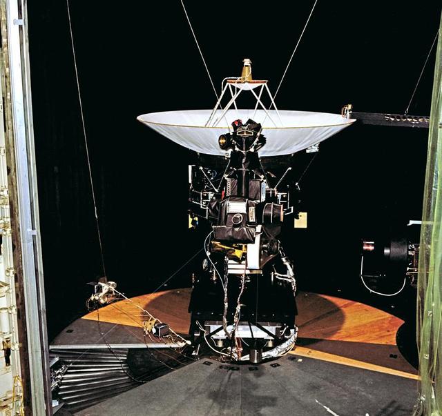
This archival photo shows the Voyager proof test model, which did not fly in space, in the 25-foot space simulator chamber at NASA's Jet Propulsion Laboratory, Pasadena, California. https://photojournal.jpl.nasa.gov/catalog/PIA21726
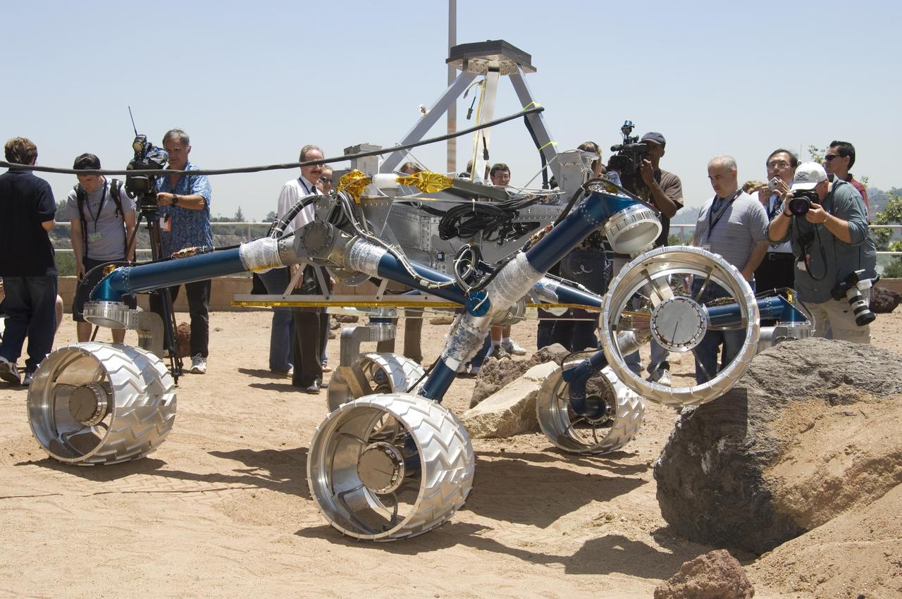
Onlookers watch as Scarecrow, a mobility-testing model for NASA Mars Science Laboratory, easily conquers boulders in the Mars Yard testing area at NASA Jet Propulsion Laboratory.

This archival photo shows the Voyager proof test model, which did not fly in space, in the 25-foot space simulator chamber at NASA's Jet Propulsion Laboratory on December 3, 1976. https://photojournal.jpl.nasa.gov/catalog/PIA21735
Members of NASA's Mars Helicopter team prepare the flight model (vehicle going to Mars) for a test in the Space Simulator, a 25-foot-wide (7.62-meter-wide) vacuum chamber at NASA's Jet Propulsion Laboratory in Pasadena, California. The image was taken on Jan. 18, 2019. https://photojournal.jpl.nasa.gov/catalog/PIA23156
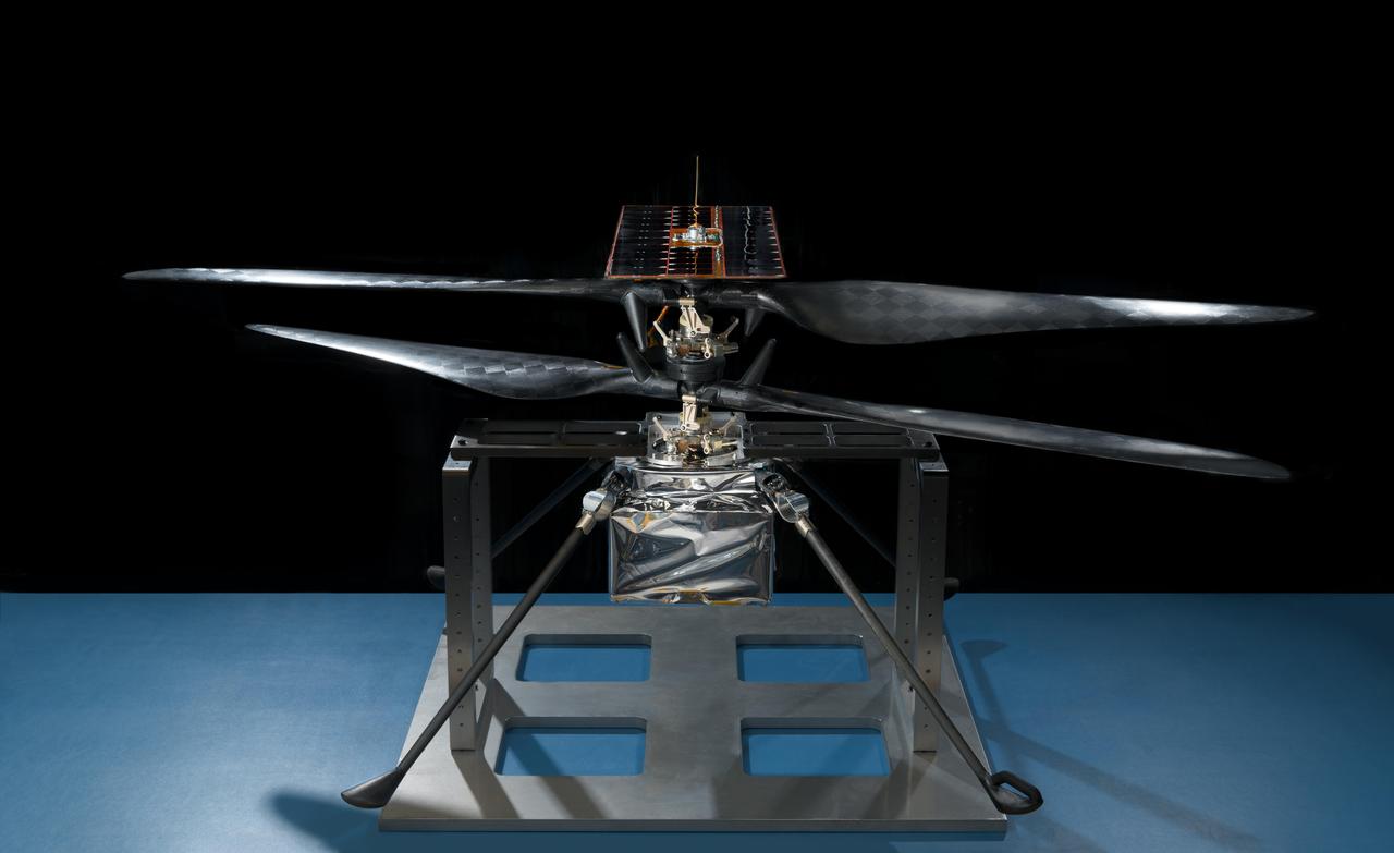
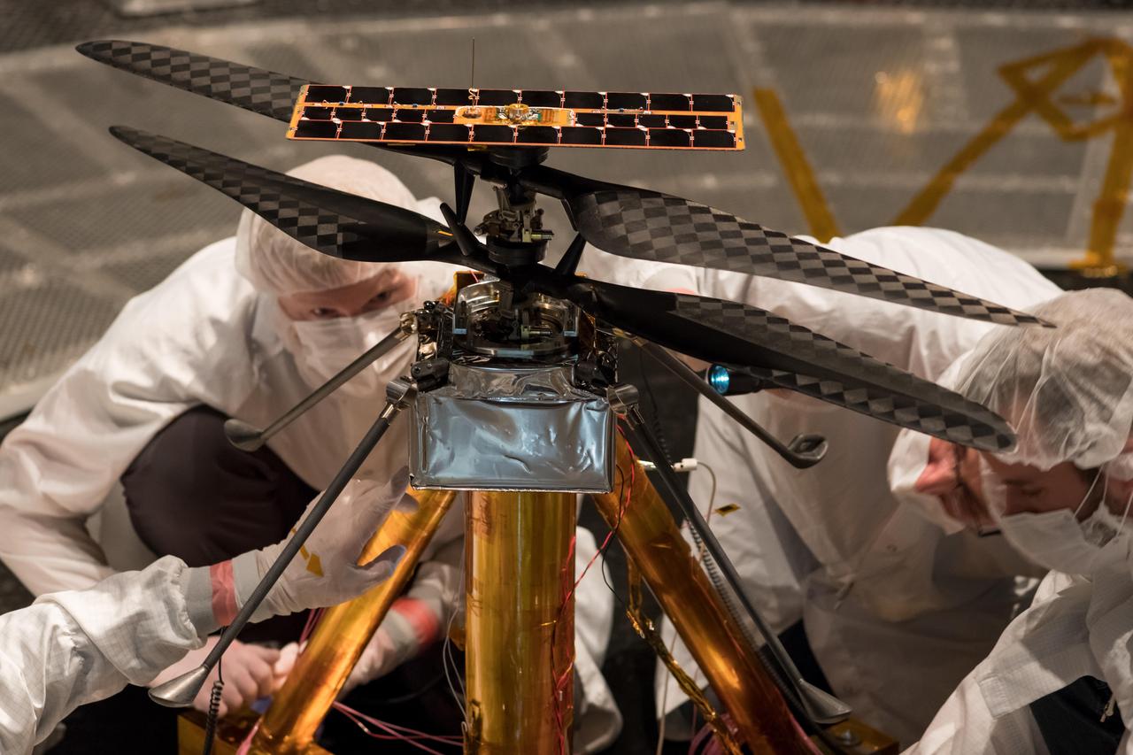
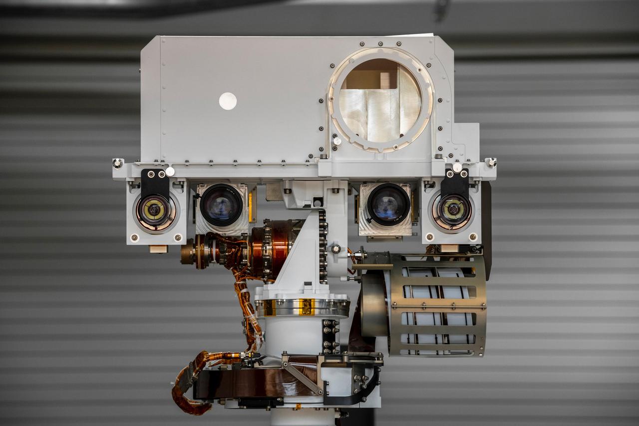
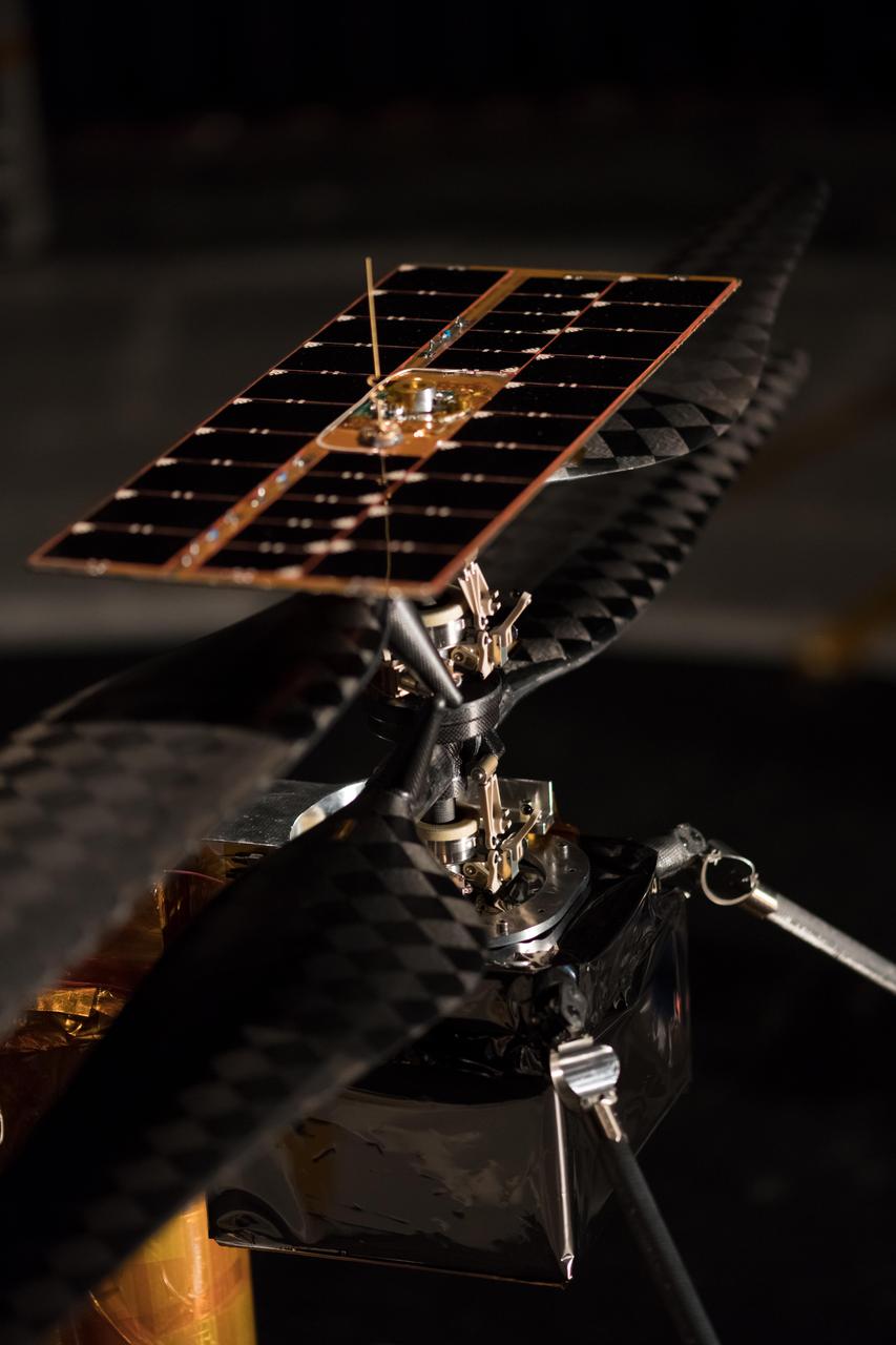
This image of the flight model of NASA's Mars Helicopter was taken on Feb. 14, 2019, in a cleanroom at NASA's Jet Propulsion Laboratory in Pasadena, California. The aluminum base plate, side posts, and crossbeam around the helicopter protect the helicopter's landing legs and the attachment points that will hold it to the belly of the Mars 2020 rover. https://photojournal.jpl.nasa.gov/catalog/PIA23151
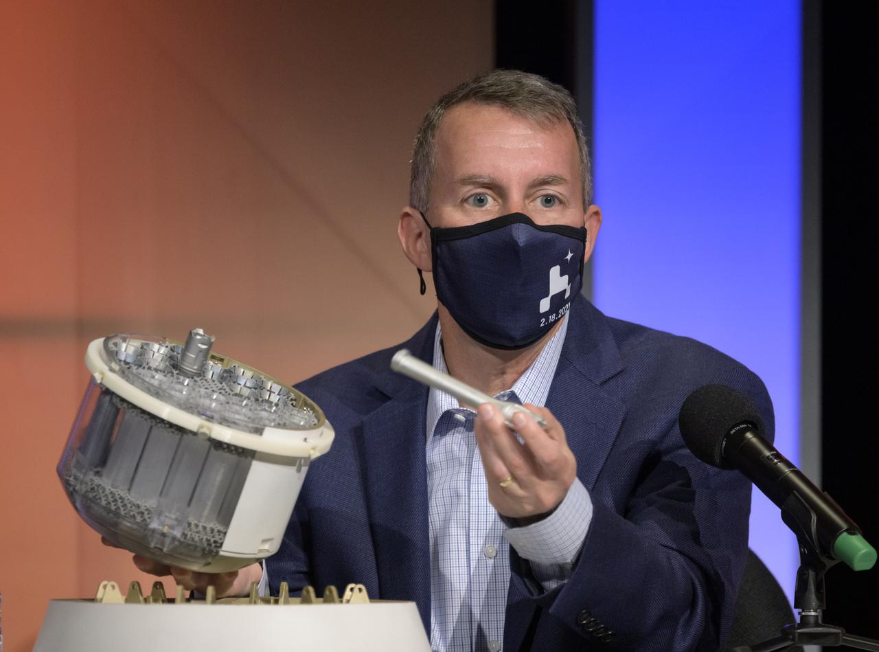
This engineering model of Mars Oxygen In-Situ Resource Utilization Experiment (MOXIE) instrument is about to undergo vibration testing in a lab at the Jet Propulsion Laboratory in Pasadena, California. Vibration tests demonstrate the ability of instruments to survive the extreme conditions of both a rocket launch from Earth and a landing on Mars. https://photojournal.jpl.nasa.gov/catalog/PIA24202
Mars Sample Return program manager, JPL, Bobby Braun, shows a concept model of NASA's orbiting sample container, which will hold tubes of Martian rock and soil samples that will be returned to Earth through a Mars sample return campaign during a NASA Perseverance rover press briefing about the search for ancient life at Mars and about samples to be brought back to Earth on a future mission, Wednesday, Feb. 17, 2021, at NASA's Jet Propulsion Laboratory in Pasadena, California. The Perseverance Mars rover is due to land on Mars Thursday, Feb. 18, 2021. A key objective for Perseverance’s mission on Mars is astrobiology, including the search for signs of ancient microbial life. The rover will characterize the planet’s geology and past climate, pave the way for human exploration of the Red Planet, and be the first mission to collect and cache Martian rock and regolith. Photo Credit: (NASA/Bill Ingalls)

Mars Sample Return program manager, JPL, Bobby Braun, shows a concept model of NASA's orbiting sample container, which will hold tubes of Martian rock and soil samples that will be returned to Earth through a Mars sample return campaign during a NASA Perseverance rover press briefing about the search for ancient life at Mars and about samples to be brought back to Earth on a future mission, Wednesday, Feb. 17, 2021, at NASA's Jet Propulsion Laboratory in Pasadena, California. The Perseverance Mars rover is due to land on Mars Thursday, Feb. 18, 2021. A key objective for Perseverance’s mission on Mars is astrobiology, including the search for signs of ancient microbial life. The rover will characterize the planet’s geology and past climate, pave the way for human exploration of the Red Planet, and be the first mission to collect and cache Martian rock and regolith. Photo Credit: (NASA/Bill Ingalls)

This archival photo shows the Voyager Proof Test Model (in the foreground right of center) undergoing a mechanical preparation and weight center of gravity test at NASA's Jet Propulsion Laboratory, Pasadena, California, on January 12, 1977. https://photojournal.jpl.nasa.gov/catalog/PIA21476
Members of the NASA Mars Helicopter team inspect the flight model (the actual vehicle going to the Red Planet), inside the Space Simulator, a 25-foot-wide (7.62-meter-wide) vacuum chamber at NASA's Jet Propulsion Laboratory in Pasadena, California, on Feb. 1, 2019. https://photojournal.jpl.nasa.gov/catalog/PIA23155
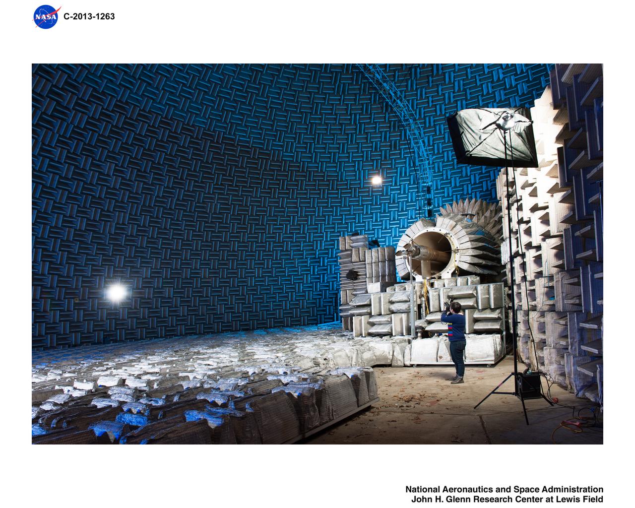
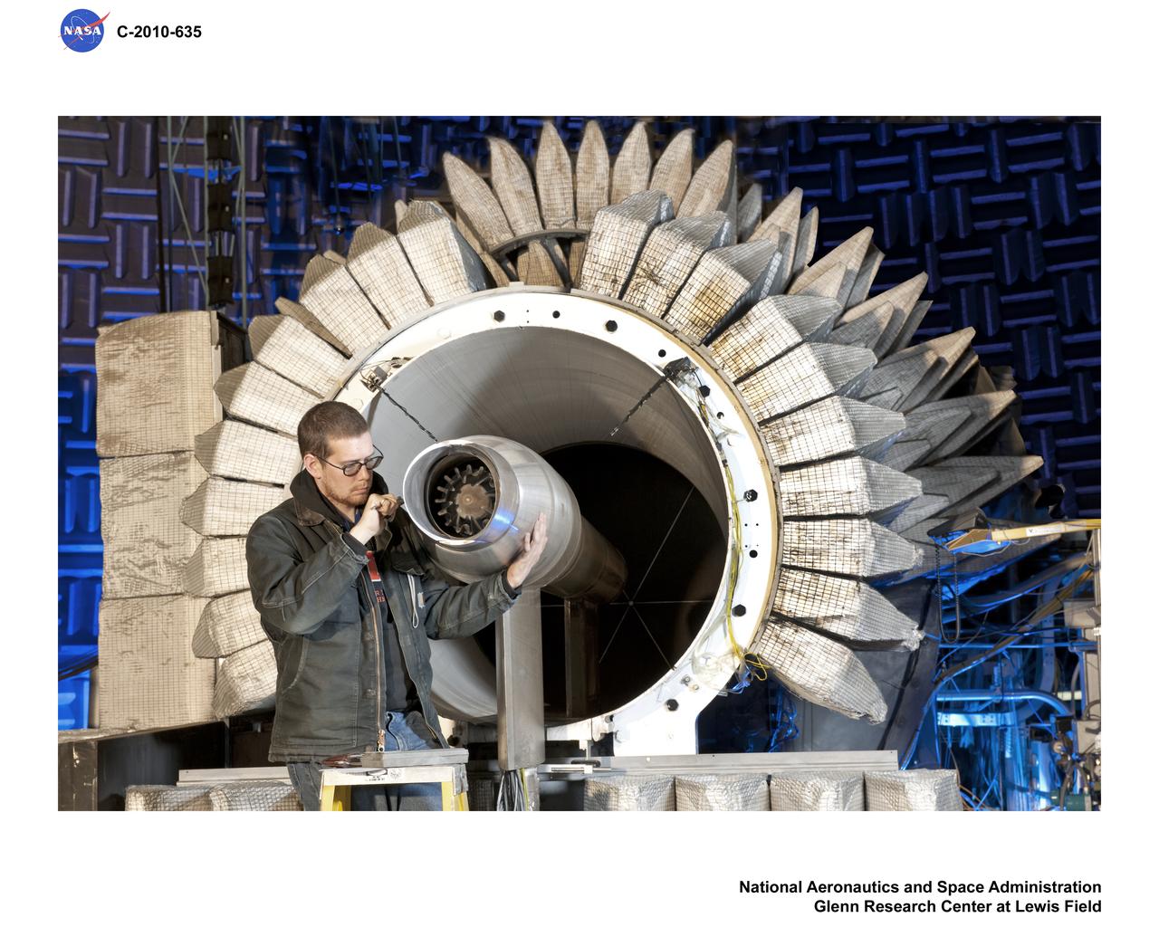
Twin Jet Model, Nozzle Acoustic Test Rig, NATR, Aeroacoustic Propulsion Laboratory, AAPL
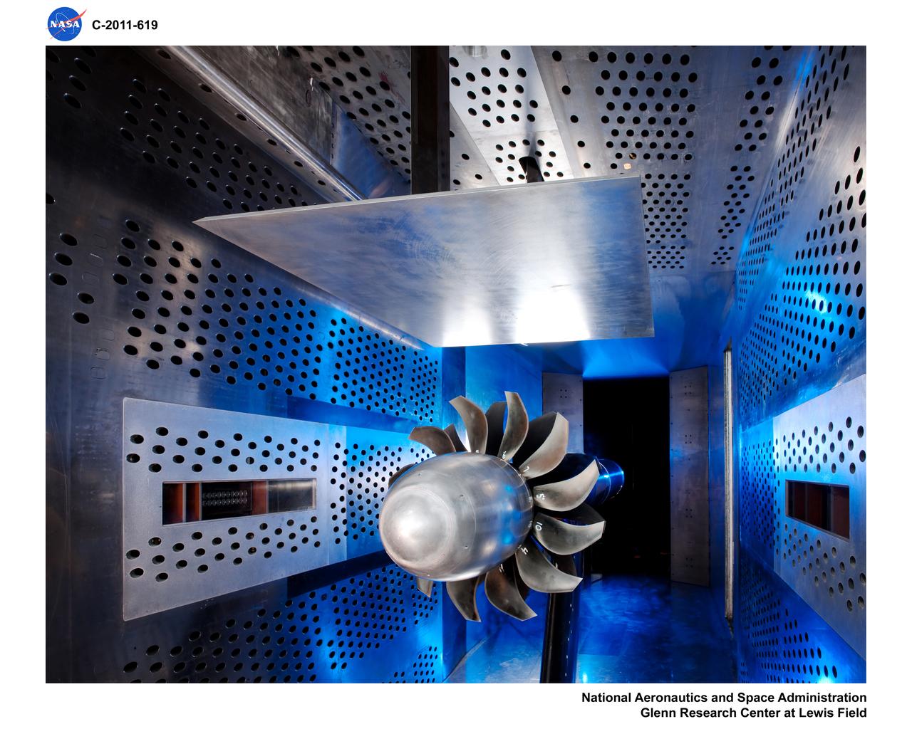
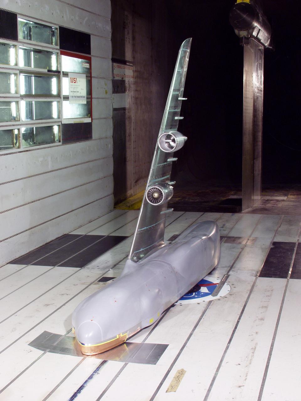
Air-Breathing Propulsion - General Electric Open Rotor Model in the 8x6-Foot Supersonic Wind Tunnel

Twin Jet Model, Nozzle Acoustic Test Rig, NATR, Aeroacoustic Propulsion Laboratory, AAPL
ForeSight, a fully functional, full-size model of NASA's InSight lander, sits in a lab space that has been sculpted to match terrain in front of the real lander on Mars. This work was done at NASA's Jet Propulsion Laboratory in Pasadena, California. https://photojournal.jpl.nasa.gov/catalog/PIA22953
This image shows a test using an engineering model of the soil scoop for NASA Mars rover Curiosity. The scoop dips to about 1.4 inches 3.5 centimeters deep. This test took place at NASA Jet Propulsion Laboratory, Pasadena , Calif., in 2011.
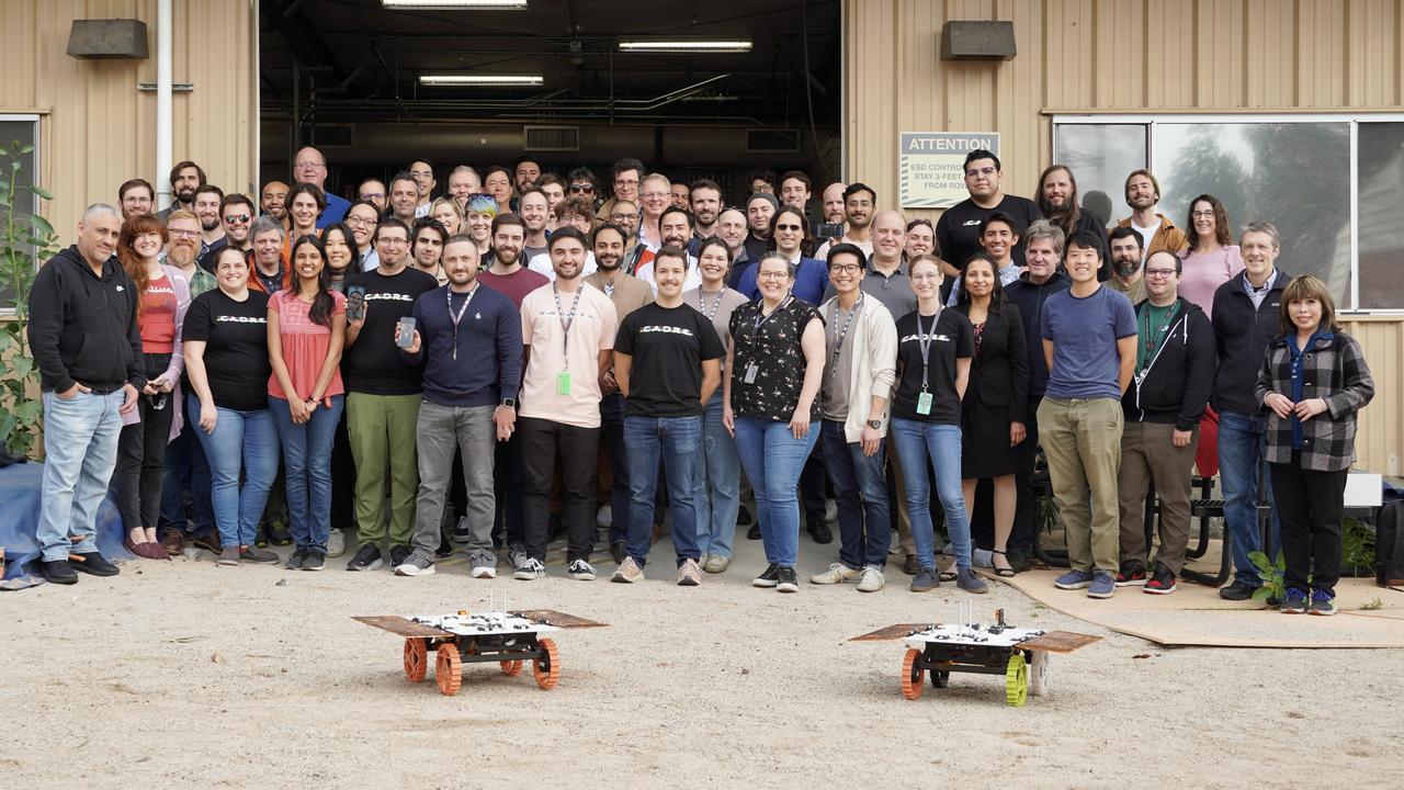
Members of NASA's CADRE (Cooperative Autonomous Distributed Robotic Exploration) technology demonstration team pose with two full-scale development model rovers in the Mars Yard at the agency's Jet Propulsion Laboratory in Southern California in January 2024. The project is designed to show that a group of robotic spacecraft can work together as a team to accomplish tasks and record data autonomously – without explicit commands from mission controllers on Earth. Three small rovers will ride aboard a lunar lander that will carry the project's base station and camera assembly. The rovers shown here are similar in size and appearance to the flight models that will travel to the Moon. Equipped with flight software and autonomy capabilities, these development models were used in a series of Mars Yard tests that helped confirm CADRE hardware and software can work together to accomplish key goals for the project. https://photojournal.jpl.nasa.gov/catalog/PIA26170
Teddy Tzanetos, MiMi Aung and Bob Balaram of NASA's Mars Helicopter project observe a flight test. The image was taken on Jan. 18, 2019 as the flight model of the Mars Helicopter was tested in the Space Simulator, a 25-foot-wide (7.62 meter-wide) vacuum chamber at NASA's Jet Propulsion Laboratory in Pasadena, California. https://photojournal.jpl.nasa.gov/catalog/PIA23161

This archival photo shows the Voyager Proof Test Model undergoing a mechanical preparation and weight center of gravity test at NASA's Jet Propulsion Laboratory, Pasadena, California, on January 12, 1977. The stack of three white cylinders seen near center is a stand-in for the spacecraft's power generators (called RTGs). Above that, a silvery canister holds the spacecraft's magnetometer in its stowed configuration. https://photojournal.jpl.nasa.gov/catalog/PIA21477
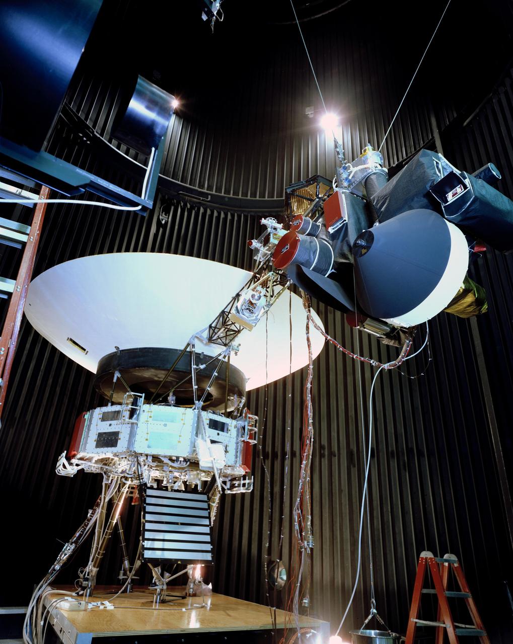
This archival photo shows the Voyager proof test model, which did not fly in space, in the 25-foot space simulator chamber at NASA's Jet Propulsion Laboratory, Pasadena, California, on December 3, 1976. The spacecraft is seen here with its scan platform, which holds several of its science instruments, in the deployed position. https://photojournal.jpl.nasa.gov/catalog/PIA21734
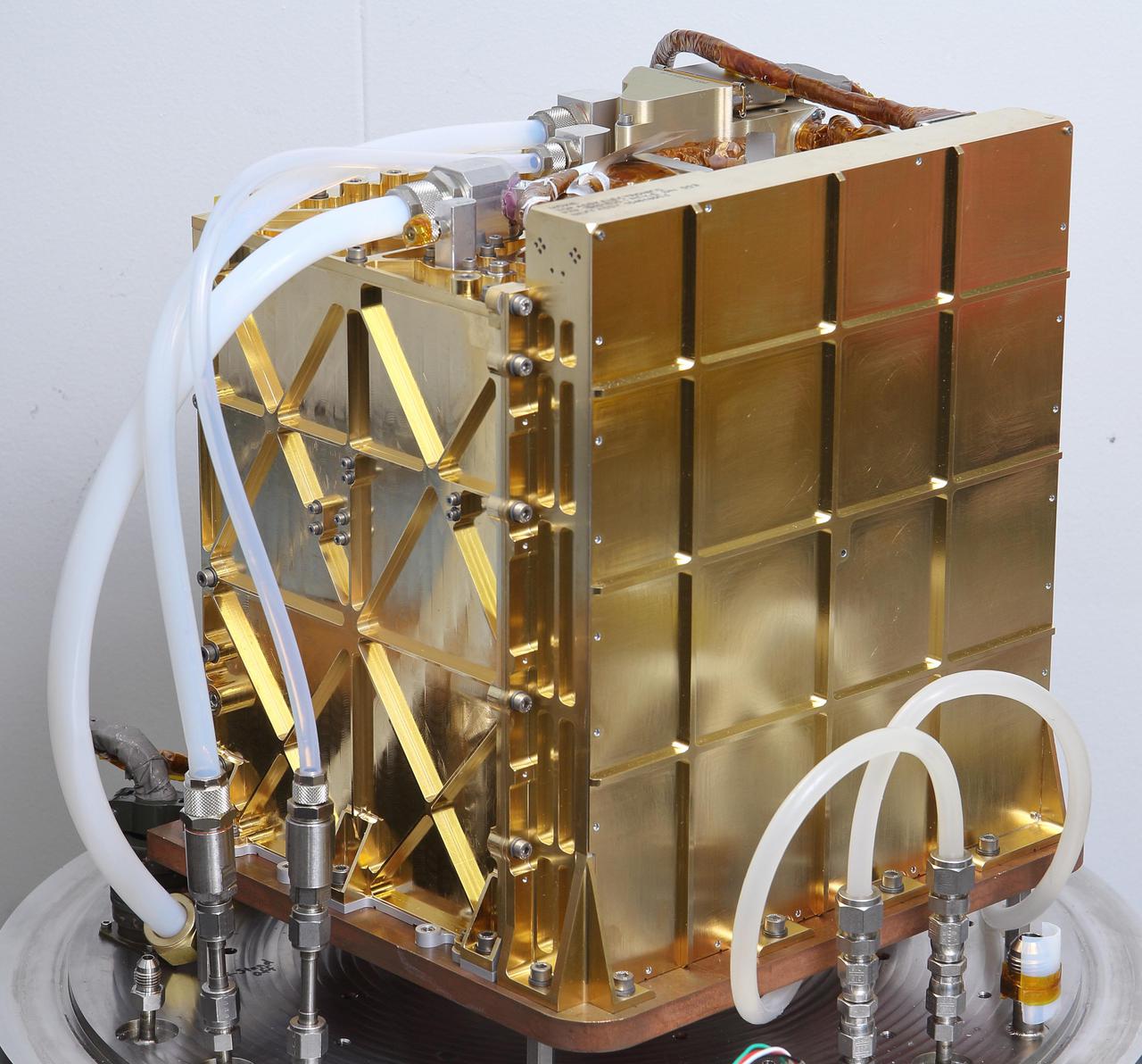
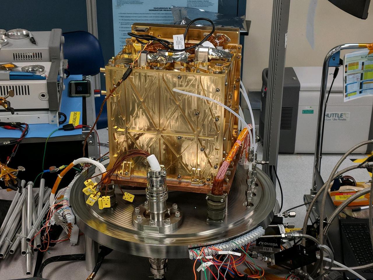
The engineering model (EM), an almost identical twin of MOXIE, is used for testing in the lab at NASA's Jet Propulsion Laboratory in Pasadena, California. Inside this gold-plated aluminum box is the Solid Oxide Electrolysis unit, or SOXE, the heart of MOXIE. Using an electrochemical process called electrolysis, SOXE takes in the carbon dioxide gas and splits it into carbon monoxide and oxygen, which is measured for purity, filtered, and then released back into the Mars atmosphere. Tubes to take in the Mars atmosphere and vent oxygen and carbon monoxide produced by the EM are connected at the top of the EM. The electronics needed to run this complex machine are housed inside the larger sidewall seen on the right. https://photojournal.jpl.nasa.gov/catalog/PIA24201
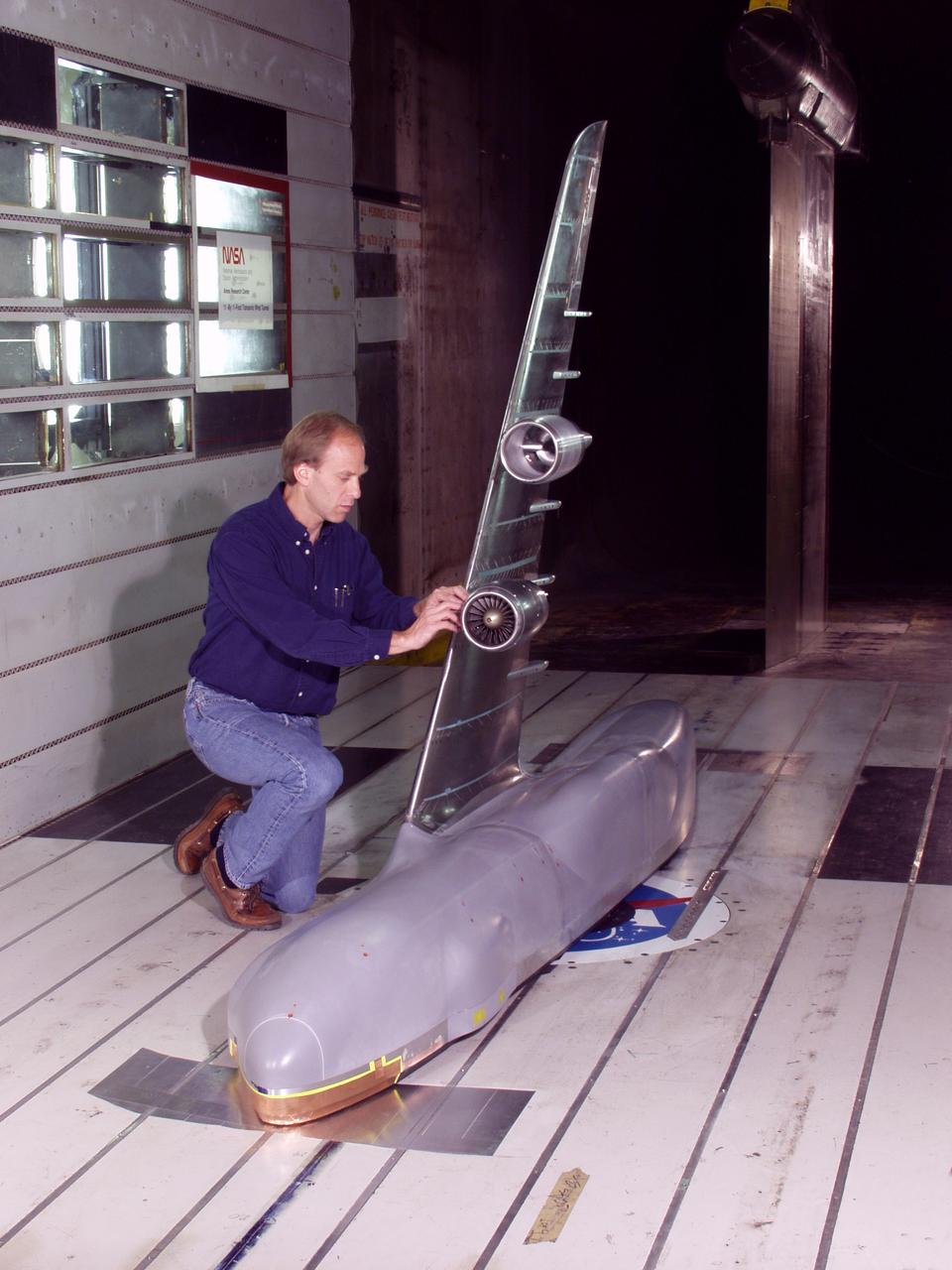
C-5 Re-engineering and Realiability Program semi-span model; 11ft w.t. Test-11-0103; Throught flow nacelle and inboard nacelle with turbine propulsion systems unit with Doug Atler
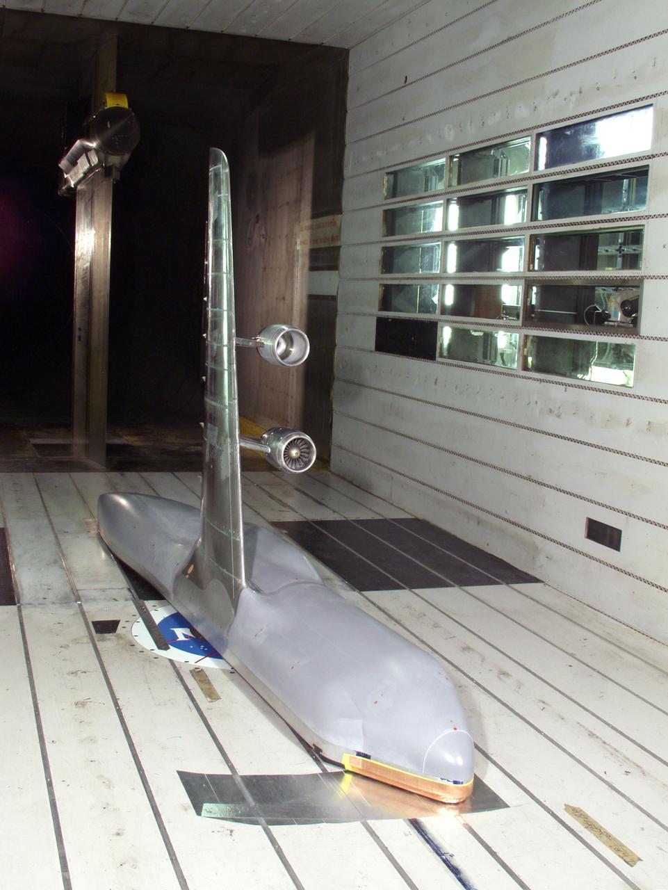
C-5 Re-engineering and Realiability Program semi-span model; 11ft w.t. Test-11-0103; Throught flow nacelle and inboard nacelle with turbine propulsion systems unit
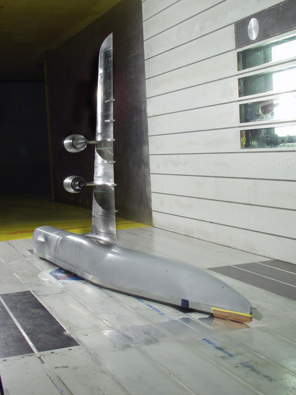
C-5 Re-engineering and Realiability Program semi-span model; 11ft w.t. Test-11-0103; Throught flow nacelle and inboard nacelle with turbine propulsion systems unit
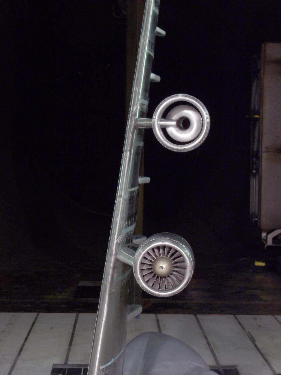
C-5 Re-engineering and Realiability Program semi-span model; 11ft w.t. Test-11-0103; Throught flow nacelle and inboard nacelle with turbine propulsion systems unit
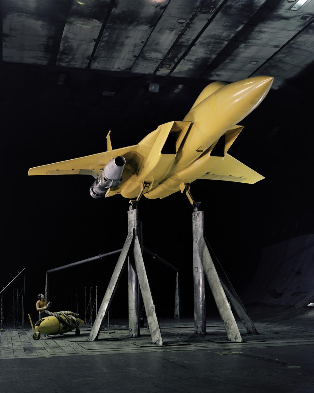
AST (Advanced Supersonic Technology) Propulsion Noise Research test on the F-15 model with nacelle in the 40x80ft Subsonic Wind Tunnel at Ames Research Center, Mt View, CA
C-5 Re-engineering and Realiability Program semi-span model; 11ft w.t. Test-11-0103; Throught flow nacelle and inboard nacelle with turbine propulsion systems unit
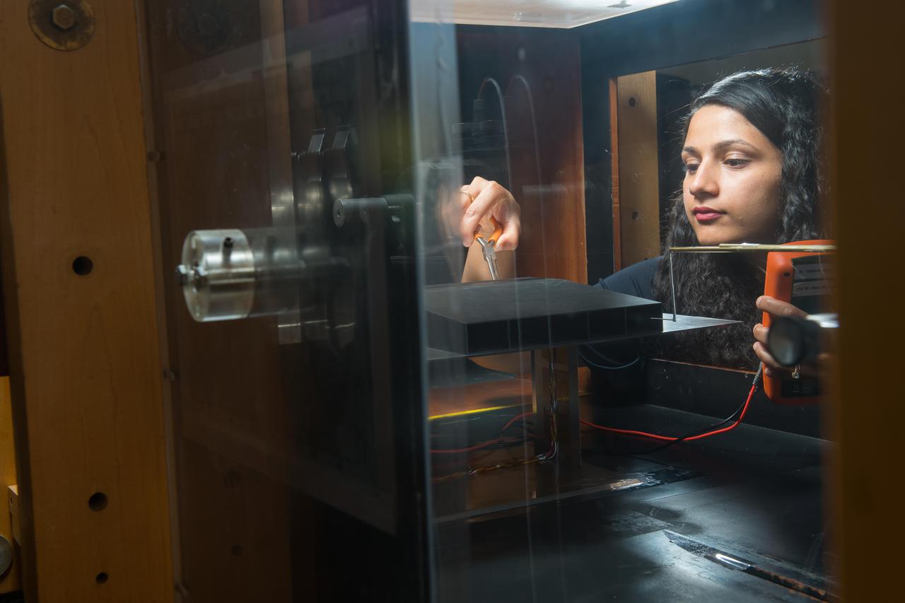
New testing is underway in the Aero-Acoustic Propulsion Laboratory (AAPL) at NASA's Glenn Research Center. The research focuses on a model called the Highly Variable Cycle Exhaust System -- a 0.17 scale model of an exhaust system that will operate at subsonic, transonic and supersonic exhaust speeds in a future supersonic business jet. The model features ejector doors used at different angles. Researchers are investigating the impact of these ejectors on the resulting acoustic radiation. Here, Steven Sedensky, a mechanical engineer with Jacobs Sverdrup, takes measurements of the ejector door positions.
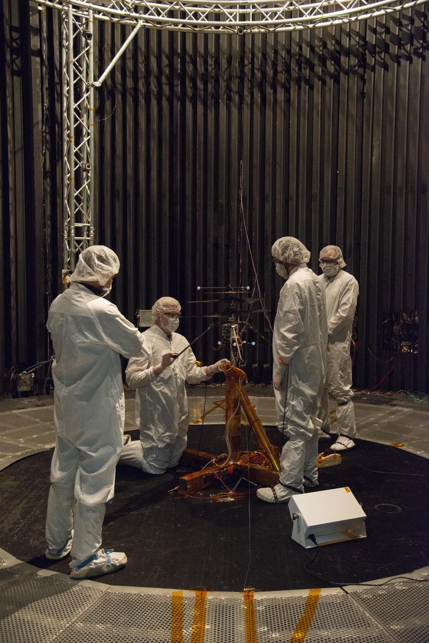
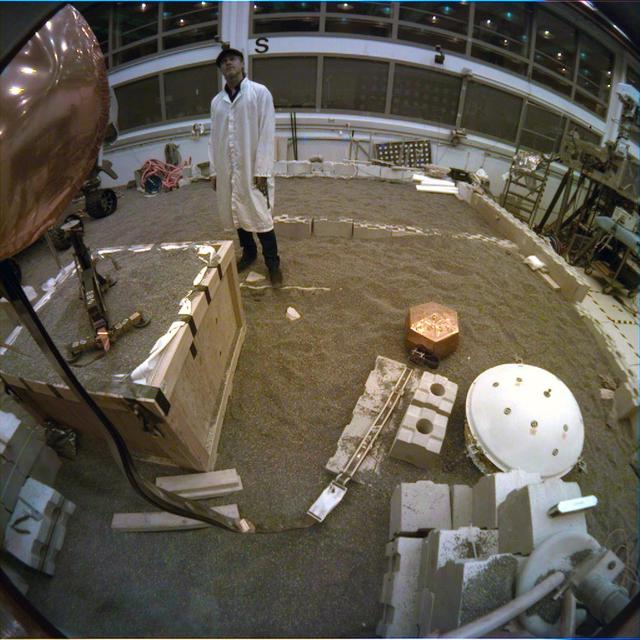
The Shooting Star Experiment (SSE) is designed to develop and demonstrate the technology required to focus the sun's energy and use the energy for inexpensive space Propulsion Research. Pictured is an engineering model (Pathfinder III) of the Shooting Star Experiment (SSE). This model was used to test and characterize the motion and deformation of the structure caused by thermal effects. In this photograph, alignment targets are being placed on the engineering model so that a theodolite (alignment telescope) could be used to accurately measure the deformation and deflections of the engineering model under extreme conditions, such as the coldness of deep space and the hotness of the sun as well as vacuum. This thermal vacuum test was performed at the X-Ray Calibration Facility because of the size of the test article and the capabilities of the facility to simulate in-orbit conditions
A test model of the boom that will be used for the magnetometer aboard NASA's Europa Clipper spacecraft is readied in NASA's Jet Propulsion Laboratory in Southern California. Called a dynamic test model, it is an exact duplicate of the Europa Clipper Magnetometer (ECM) boom that will fly on Europa Clipper. To fit aboard the rocket, the boom will be stowed in a canister and will deploy to its full length of 25 feet (8.5 meters) in the days after launch. The ECM will allow scientists to measure Europa's magnetic field and to measure the salinity and depth of Europa's internal global ocean. NASA scientists believe Jupiter's moon Europa may have the potential to harbor existing life, because of the internal ocean. Europa Clipper will swoop around Jupiter on an elliptical path, dipping close to the moon on each flyby. Understanding Europa's habitability will help scientists better understand how life developed on Earth and the potential for finding life beyond our planet. Europa Clipper is set to launch in 2024. https://photojournal.jpl.nasa.gov/catalog/PIA24786
A model Sample Recovery Helicopter drives and positions itself over a sample tube during a test in the Mars Yard at NASA's Jet Propulsion Laboratory in Southern California. Two Sample Recovery Helicopters are slated to fly to Mars as part of the Mars Sample Return campaign. NASA is developing the Sample Recovery Helicopters to serve as backups to the agency's Perseverance rover in transporting sample tubes to the Sample Retrieval Lander. These helicopters are follow-ons to NASA's Ingenuity Mars Helicopter, which arrived at the Red Planet in the belly of Perseverance in February 2021. The Sample Recovery Helicopters have wheels instead of feet, as well as a small manipulator arm with a two-fingered gripper capable of carrying precious sample tubes. Testing of the Sample Recovery Helicopters is ongoing. The testbed was made by AeroVironment Inc. Movie available at https://photojournal.jpl.nasa.gov/catalog/PIA25320
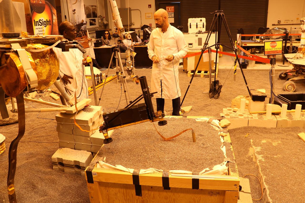
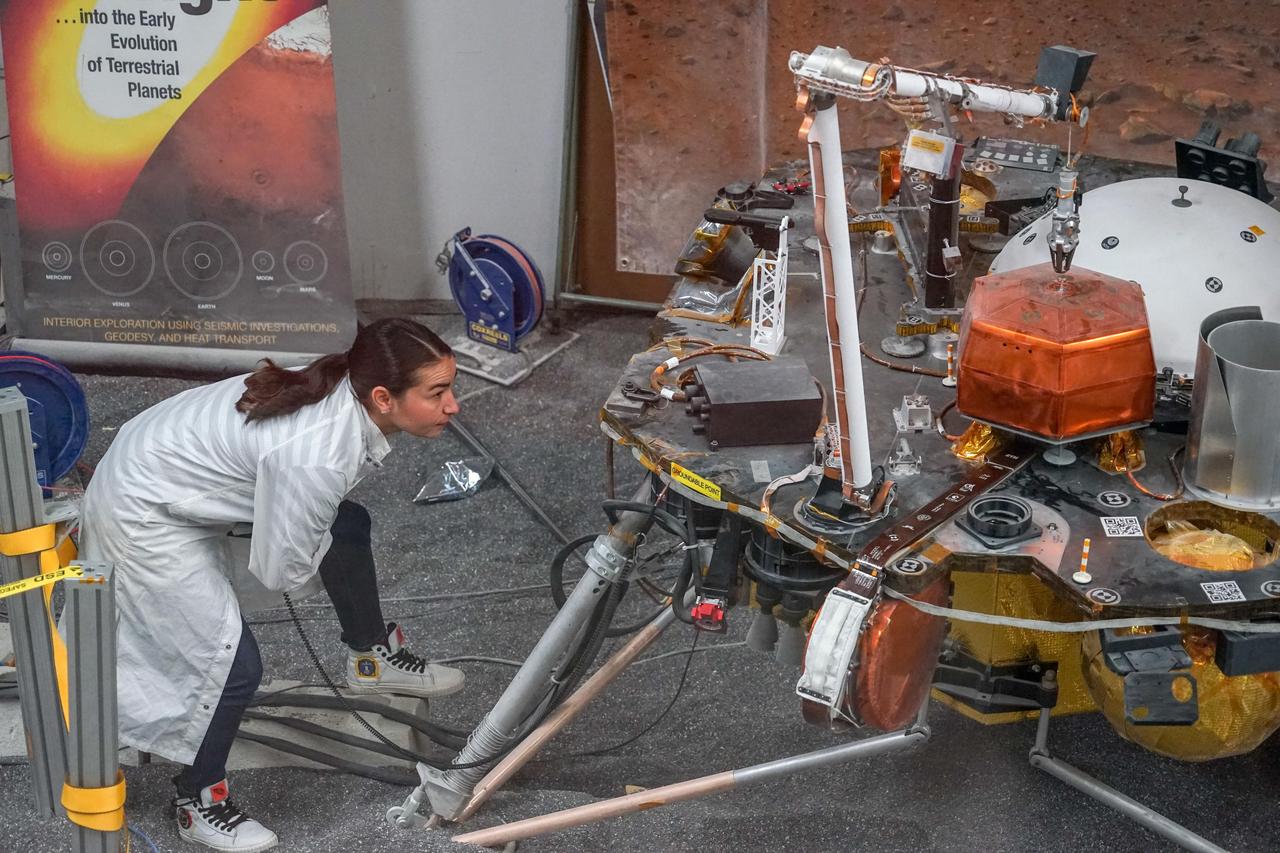
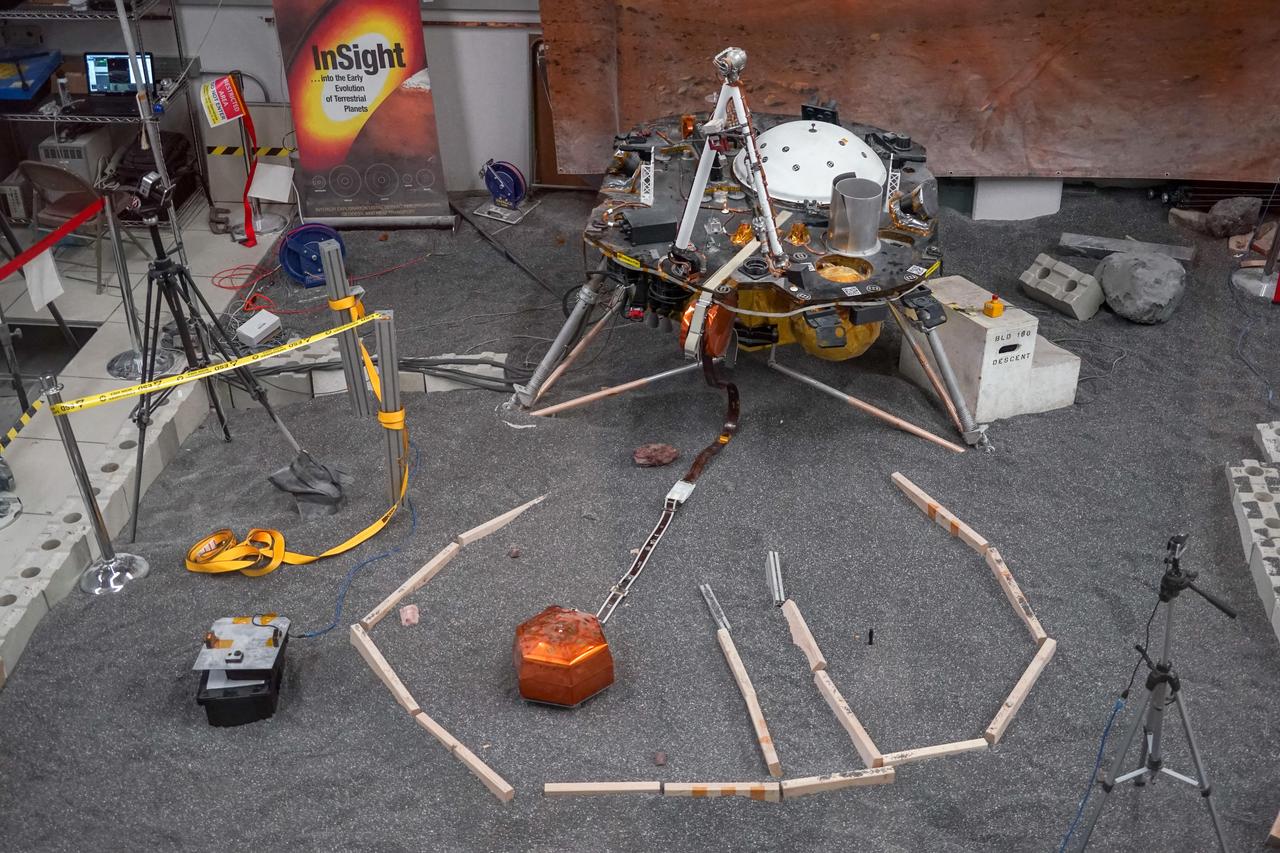
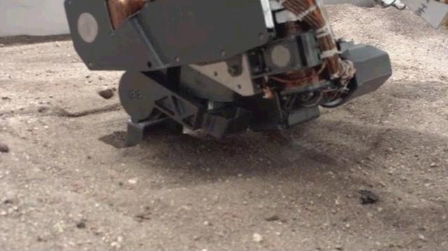
Engineers in a Mars-like test area at NASA's Jet Propulsion Laboratory try possible strategies to aid the Heat Flow and Physical Properties Package (HP3) on NASA's InSight lander, using engineering models of the lander, robotic arm and instrument. In this image, the model's robotic arm is lifting up part of HP3 to expose the self-hammering mole that is partially embedded in the testbed soil. Standing mid-ground are engineers Ashitey Trebi-Ollennu (left) and Troy Lee Hudson (right). Lights in the testbed intended to simulate Mars' lighting conditions give the image an orange tint. Engineers at the German Aerospace Center (DLR), which provided HP3, have also been working on strategies to help the probe. https://photojournal.jpl.nasa.gov/catalog/PIA23272
Marshall space Flight Center engineers helped North American Marine Jet (NAMJ), Inc. improve the proposed design of a new impeller for a jet-propulsion system. With a three-dimensional computer model of the new marine jet engine blades, engineers were able to quickly create a solid polycarbonate model of it. The rapid prototyping allowed the company to avoid many time-consuming and costly steps in creating the impeller.
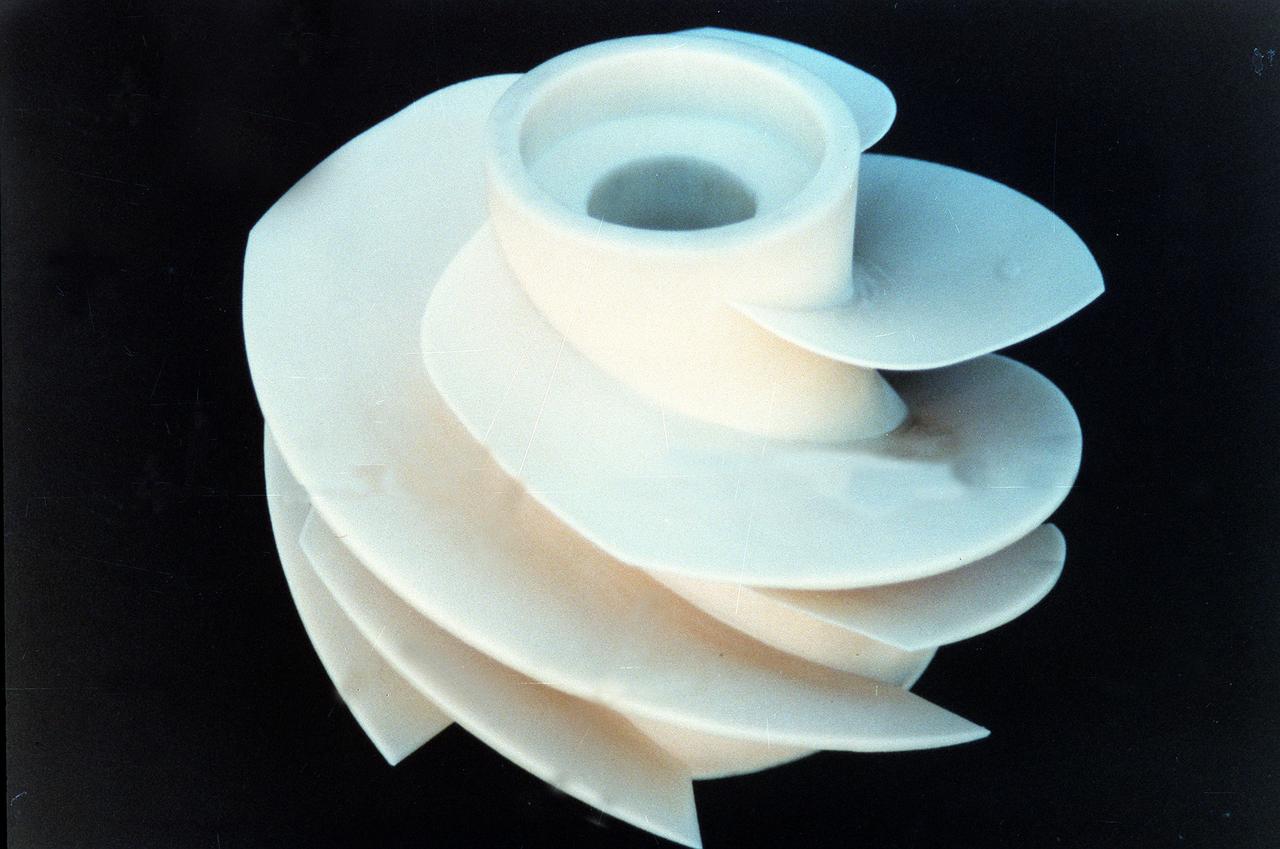
Marshall Space Flight Center engineers helped North American Marine Jet (NAMJ), Inc. improve the proposed design of a new impeller for jet propulsion system. With a three-dimensional computer model of the new marine jet engine blades, engineers were able to quickly create a solid ploycarbonate model of it. The rapid prototyping allowed the company to avoid many time-consuming and costly steps in creating the impeller.
The Mars Helicopter team gathers for a group photo at NASA's Jet Propulsion Laboratory in Southern California on Dec. 3, 2018. Holding a full-size model of the helicopter, named Ingenuity, is MiMi Aung, the project manager at JPL. https://photojournal.jpl.nasa.gov/catalog/PIA22649
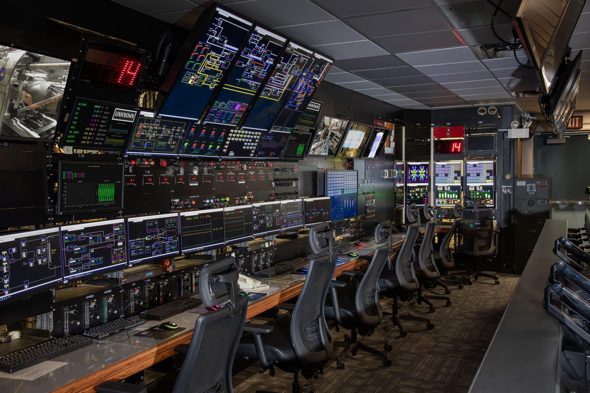
Gunnar Kadlic monitors the data system in the NASA Glenn's Propulsion System Lab (PSL) recently remodeled control room. This is where jet and rocket engines are tested at GRC. This re-modeled control room offers better test monitoring and work stations for test engineers and technicians.
In a Mars-like environment at NASA's Jet Propulsion Laboratory, the fish-eye camera aboard the engineering model of NASA's InSight lander snapped this image of the actor Brad Pitt on Sept. 6, 2019. This picture, which has been white-balanced to remove the orange-red tint of the Mars lights in the room, was taken by the instrument context camera, bolted to the deck of the lander model. The InSight replica is located in JPL's In-Situ Instrument Laboratory and used for test purposes. Pitt visited JPL to learn about real space technology after filming his space-themed movie "Ad Astra." https://photojournal.jpl.nasa.gov/catalog/PIA23278
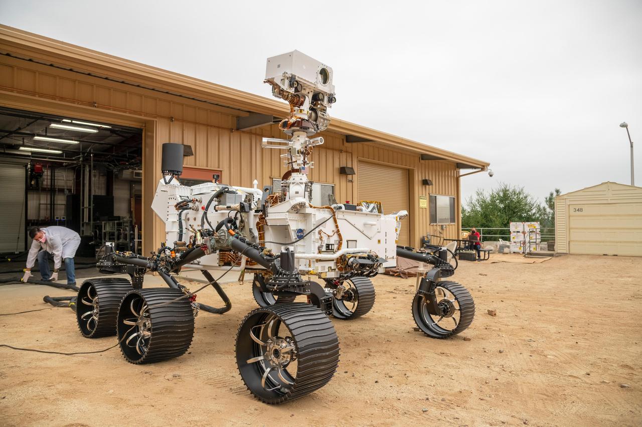
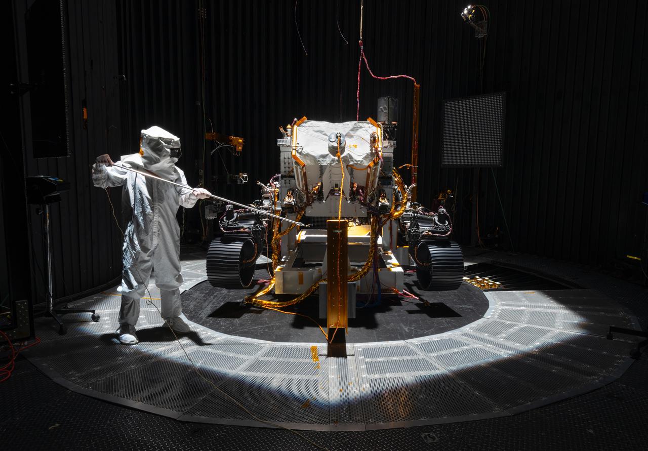
The full-scale engineering model of NASA's Perseverance rover has put some dirt on its wheels. This vehicle system test bed (VSTB) rover moved into its home — a garage facing the Mars Yard at NASA's Jet Propulsion Laboratory in Southern California — on Sept. 4, 2020. It drove onto simulated Martian surface of the Mars Yard — a dirt field at JPL studded with rocks and other obstacles — for the first time on Sept. 8. The VSTB rover is also known as OPTIMISM (Operational Perseverance Twin for Integration of Mechanisms and Instruments Sent to Mars). A key objective for Perseverance's mission on Mars is astrobiology, including the search for signs of ancient microbial life. The rover will also characterize the planet's climate and geology, pave the way for human exploration of the Red Planet, and be the first planetary spacecraft to collect and cache Martian rock and regolith (broken rock and dust). Subsequent missions, currently under consideration by NASA in cooperation with the European Space Agency, would send spacecraft to Mars to collect these cached samples from the surface and return them to Earth for in-depth analysis. The Mars 2020 mission is part of a larger program that includes missions to the Moon as a way to prepare for human exploration of the Red Planet. Charged with returning astronauts to the Moon by 2024, NASA will establish a sustained human presence on and around the Moon by 2028 through NASA's Artemis lunar exploration plans. https://photojournal.jpl.nasa.gov/catalog/PIA23966
An engineering model of NASA's Mars 2020 rover makes tracks during a driving test in the Mars Yard, an area that simulates Mars-like conditions at NASA's Jet Propulsion Laboratory in Pasadena, California. This image was taken on Dec. 3, 2019, as engineers were trying out the software that will command the rover to move. Mars 2020 will launch from Cape Canaveral Air Force Station in Florida as early as July 2020. It will land at Jezero Crater on Feb. 18, 2021. JPL is building and will manage operations of the Mars 2020 rover for NASA. NASA's Launch Services Program, based at the agency's Kennedy Space Center in Florida, is responsible for launch management. Mars 2020 is part of a larger program that includes missions to the Moon as a way to prepare for human exploration of the Red Planet. Charged with returning astronauts to the Moon by 2024, NASA will establish a sustained human presence on and around the Moon by 2028 through NASA's Artemis lunar exploration plans. For more information about the mission, go to https://mars.nasa.gov/mars2020/. https://photojournal.jpl.nasa.gov/catalog/PIA23498

A model of the Power and Propulsion Element (PPE) is seen on display during an event where NASA is outlining how the agency is executing President Donald J. Trump’s National Space Policy and accelerating preparations for America’s return to the surface of the Moon by 2028, Tuesday, March 24, 2026, at the Mary W. Jackson NASA Headquarters building in Washington. During the event NASA leadership provided updates on mission priorities, including sending the first astronauts to the lunar surface in more than 50 years, establishing the initial elements of a permanent lunar base, getting America underway in space on nuclear propulsion, and other objectives. Photo Credit: (NASA/Bill Ingalls)
Power and Propulsion Element (PPE) model is seen on display during an event where NASA is outlining how the agency is executing President Donald J. Trump’s National Space Policy and accelerating preparations for America’s return to the surface of the Moon by 2028, Tuesday, March 24, 2026, at the Mary W. Jackson NASA Headquarters building in Washington. During the event NASA leadership provided updates on mission priorities, including sending the first astronauts to the lunar surface in more than 50 years, establishing the initial elements of a permanent lunar base, getting America underway in space on nuclear propulsion, and other objectives. Photo Credit: (NASA/Bill Ingalls)
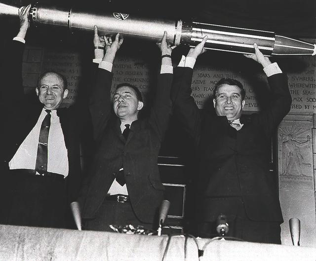
Jet Propulsion Laboratory Director Dr. William Pickering, Dr. James van Allen of the State University of Iowa, and Army Ballistic missionile Agency Technical Director Dr. Wernher von Braun triumphantly display a model of the Explorer I, America's first satellite, shortly after the satellite's launch on January 31, 1958. The Jet Propulsion Laboratory packed and tested the payload, a radiation detection experiment designed by Dr. van Allen. Dr. von Braun's rocket team at Redstone Arsenal in Huntsville, Alabama, developed the Juno I launch vehicle, a modified Jupiter-C.
The full-scale engineering model of NASA's Perseverance rover raises its "head," or remote sensing mast, at NASA's Jet Propulsion Laboratory in Southern California. This model is known as the vehicle system test bed (VSTB) rover, or OPTIMISM (Operational Perseverance Twin for Integration of Mechanisms and Instruments Sent to Mars). OPTIMISM raised its mast shortly after moving into its new home at JPL's Mars Yard on Sept. 4, 2020. The mast hosts many of the rover's cameras and scientific instruments. At the top of the mast, the large circular opening is where the SuperCam instrument will be installed on this test rover. Also visible in these images below the SuperCam "eye" are the navigation cameras (two cameras closest to the outside of the head) and the Mastcam-Z cameras inside of the navigation cameras. A key objective for Perseverance's mission on Mars is astrobiology, including the search for signs of ancient microbial life. The rover will also characterize the planet's climate and geology, pave the way for human exploration of the Red Planet, and be the first planetary spacecraft to collect and cache Martian rock and regolith (broken rock and dust). Subsequent missions, currently under consideration by NASA in cooperation with the European Space Agency, would send spacecraft to Mars to collect these cached samples from the surface and return them to Earth for in-depth analysis. The Mars 2020 mission is part of a larger program that includes missions to the Moon as a way to prepare for human exploration of the Red Planet. Charged with returning astronauts to the Moon by 2024, NASA will establish a sustained human presence on and around the Moon by 2028 through NASA's Artemis lunar exploration plans. https://photojournal.jpl.nasa.gov/catalog/PIA23967
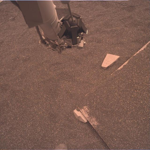
This test image from an engineering model of NASA's InSight lander shows part of the lander's robotic arm and the simulated Martian ground at a testbed at NASA's Jet Propulsion Laboratory in Pasadena, California. The testbed aims to mimic the environment InSight will encounter at Mars so engineers can prepare for the spacecraft operations to come. This image is expected to be similar to the raw or unprocessed images that InSight will send back to Earth. It was taken by the instrument deployment camera attached to InSight's robotic arm. https://photojournal.jpl.nasa.gov/catalog/PIA22827
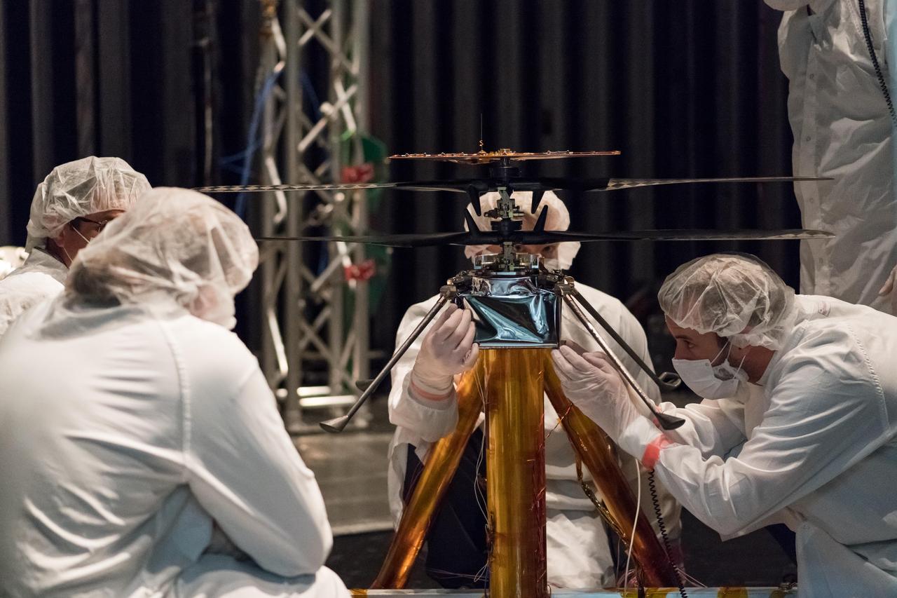
Members of NASA's Mars Helicopter team attach a thermal film enclosure to the fuselage of the flight model (the actual vehicle going to the Red Planet). The image was taken on Feb. 1, 2019, inside the Space Simulator, a 25-foot-wide (7.62-meter-wide) vacuum chamber at NASA's Jet Propulsion Laboratory in Pasadena, California. https://photojournal.jpl.nasa.gov/catalog/PIA23157
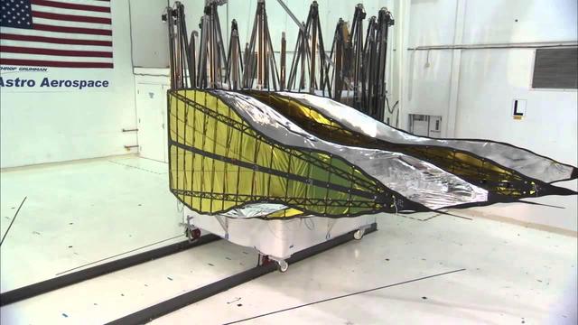
A furled first prototype starshade developed by NASA's Jet Propulsion Laboratory, shown in technology partner Astro Aerospace/Northrup Grumman's facility in Santa Barbara, California, in 2013. This design shows petals that are more extreme in shape, which properly diffracts starlight for smaller telescopes. For launch, the petals of the starshade will be wrapped around the spacecraft, then unfurled into the familiar flower-like design once in space. As shown by this 66-foot (20-meter) model, starshades can come in many shapes and sizes. http://photojournal.jpl.nasa.gov/catalog/PIA20905
Jim Fanson, Kepler project manager, at NASA's Jet Propulsion Laboratory in Pasadena, Calif. holds a model of the Kepler spacecraft as he talks about the Kepler mission during a media briefing, Thursday, Feb. 19, 2008, at NASA Headquarters in Washington. Kepler, the first mission with the ability to find planets like earth, is scheduled to launch on March 5, 2009 from Cape Canaveral Air Force Station, Fla. aboard a Delta II rocket. Photo Credit: (NASA/Paul. E. Alers)
Planetary protection engineers at NASA's Jet Propulsion Laboratory in Southern California swab engineering models of the tubes that will store Martian rock and sediment samples as part of NASA’s Mars 2020 Perseverance mission. Team members wanted to understand the transport of biological particles when the rover is taking rock cores. These measurements helped the rover team design hardware and sampling methods that meet stringent biological contamination control requirements. https://photojournal.jpl.nasa.gov/catalog/PIA23718
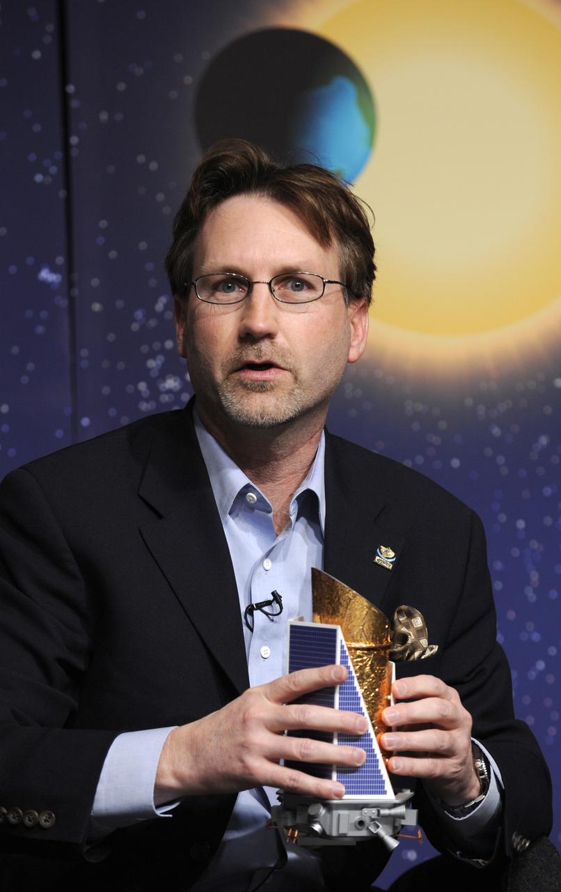
A model of the Mars InSight lander is on display during a social media briefing, Sunday, Nov. 25, 2018 at NASA's Jet Propulsion Laboratory in Pasadena, California. InSight, short for Interior Exploration using Seismic Investigations, Geodesy and Heat Transport, is a Mars lander designed to study the "inner space" of Mars: its crust, mantle, and core. InSight is scheduled to touch down on the Red Planet at approximately noon PST (3 p.m. EST) on Nov. 26. Photo Credit: (NASA/Bill Ingalls)
More than 1,500 individual pieces of carbon fiber, flight-grade aluminum, silicon, copper, foil and foam go into a Mars Helicopter. This image of the Flight Model (the actual vehicle going to the Red Planet), was taken on Feb. 1, 2019 when the helicopter was inside the Space Simulator, a 25-foot (7.62 meter) wide vacuum chamber at NASA's Jet Propulsion Laboratory in Pasadena, California. https://photojournal.jpl.nasa.gov/catalog/PIA23158
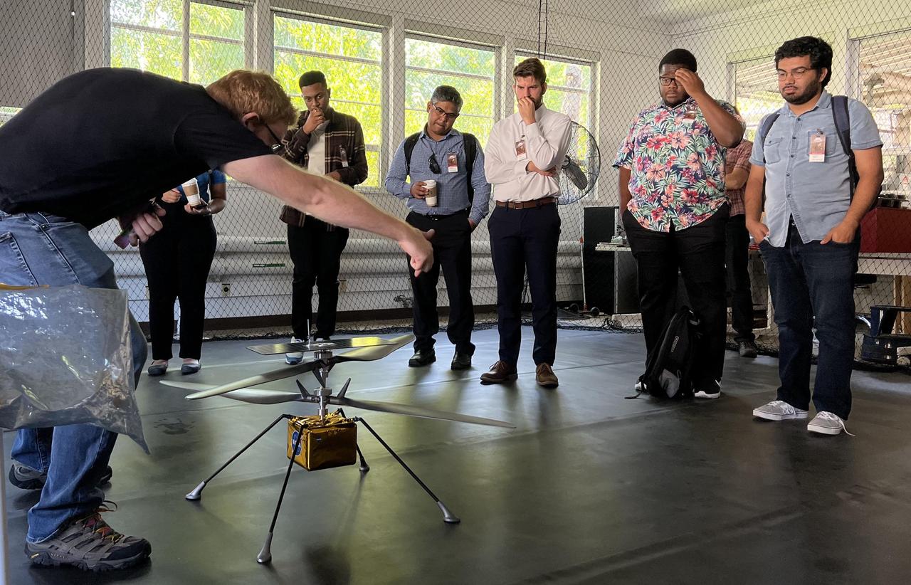
Participants in NASA's Minority Serving Institutions Space Accelerator program surround a full-scale model of NASA's Mars Ingenuity Helicopter as engineer Michael Starch discusses the mission. The group was visiting NASA's Jet Propulsion Laboratory on Aug. 18, 2022. These participants were members of three teams named as awardees in the first-of-its-kind accelerator program, a competition to advance the NASA's goals and meet its needs in the areas of machine learning, artificial intelligence, and development of autonomous systems while also engaging underrepresented academic institutions and reducing barriers for them to submit ideas to the agency. The program provides funding, business training through a 10-week accelerator course, and mentorship to help the teams develop ideas for systems that can operate without human oversight for future science missions in space and on Earth. The teams were made up of professors and students from Fayetteville State University in North Carolina, University of Massachusetts Boston, and California State University, Northridge. At the conclusion of the accelerator, participants arrived in Southern California for a variety of events, including two days at JPL. The program is a partnership between NASA's Science Mission Directorate, its Earth Science Technology Office, the Minority University Research Education Project within the agency's Office of STEM Engagement, JPL, and Starburst, a global aerospace accelerator company based in Los Angeles. https://photojournal.jpl.nasa.gov/catalog/PIA25315
Engineers at NASA's Jet Propulsion Laboratory in Southern California test an engineering model of a high-frequency (HF) radar antenna that makes up part of NASA's Europa Clipper radar instrument on Dec. 17, 2019. The antenna is a 59-foot-long (18-meter-long) narrow copper tube held straight by several cables and a cross bar on the tower at right. In space, the copper tube will stick out straight on its own, but in Earth's gravity, the antenna requires supports to keep it straight for testing. The mobile tower at left holds a model of the VHF (very high-frequency) antenna so that engineers could measure the amount of energy coupled from one antenna to the other. Europa Clipper's radar instrument is called Radar for Europa Assessment and Sounding: Ocean to Near-surface, or REASON. As the spacecraft orbits Jupiter and surveys its icy moon Europa, REASON will use HF and VHF radio signals to penetrate up to 18 miles (30 kilometers) into the icy shell that covers Europa. The radio waves will bounce off subsurface features and return to the spacecraft to create images of the ice layers' internal structure. REASON will help scientists look for the moon's suspected ocean, measure ice thickness, and better understand the icy shell's interior. The instrument will also study the elevation, properties, and roughness of Europa's surface, and will prowl Europa's upper atmosphere for signs of plume activity. The antennae were built for NASA by Heliospace Corporation in Berkeley, California, and the University of Texas at Austin is the lead institution for REASON. The testing was conducted at JPL's Mesa Antenna Measurement Facility, which sits on a high plateau. With an internal global ocean twice the size of Earth's oceans combined, Europa may have the potential to harbor life. The Europa Clipper orbiter will swoop around Jupiter on an elliptical path, dipping close to the moon on each flyby to collect data. Understanding Europa's habitability will help scientists better understand how life developed on Earth and the potential for finding life beyond our planet. Europa Clipper is aiming for a launch readiness date of 2024. https://photojournal.jpl.nasa.gov/catalog/PIA24323
A researcher examines an Advanced Technology Transport model installed in the 8- by 6-Foot Supersonic Wind Tunnel at the National Aeronautics and Space Administration (NASA) Lewis Research Center. The Advanced Technology Transport concept was a 200-person supersonic transport aircraft that could cruise at Mach 0.9 to 0.98 with low noise and pollution outputs. General Electric and Pratt and Whitney responded to NASA Lewis’ call to design a propulsion system for the aircraft. The integration of the propulsion system with the airframe was one of the greatest challenges facing the designers of supersonic aircraft. The aircraft’s flow patterns and engine nacelles could significantly affect the performance of the engines. NASA Lewis researchers undertook a study of this 0.30-scale model of the Advanced Technology Transport in the 8- by 6-foot tunnel. The flow-through nacelles were located near the rear of the fuselage during the initial tests, seen here, and then moved under the wings for ensuing runs. Different engine cowl shapes were also analyzed. The researchers determined that nacelles mounted at the rear of the aircraft produced more efficient airflow patterns during cruising conditions at the desired velocities. The concept of the Advanced Technology Transport, nor any other US supersonic transport, has ever come to fruition. The energy crisis, environmental concerns, and inadequate turbofan technology of the 1970s were among the most significant reasons.
A .10-scale model of Convair’s XF-102 in the 8- by 6-Foot Supersonic Wind Tunnel at the National Advisory Committee for Aeronautics (NACA) Lewis Flight Propulsion Laboratory for jet exit studies. The XF-102 was a prototype of the F-102 Delta Dagger. The F-102 served as an interceptor against long range bombers from the Soviet Union. The aircraft was powered by a Pratt and Whitney J57 turbojet. The first prototype crashed two weeks after is first flight on October 24, 1953, just months after this photograph. Engineers then incorporated the fixed-wing design to reduce drag at supersonic speeds. The production model F-102 became the first delta-wing supersonic aircraft in operation. The 8- by 6-Foot Supersonic Wind Tunnel is used to study propulsion systems, including inlets and exit nozzles, combustion fuel injectors, flame holders, exit nozzles, and controls on ramjet and turbojet engines. Flexible sidewalls alter the tunnel’s nozzle shape to vary the Mach number during operation. A seven-stage axial compressor, driven by three electric motors that yield a total of 87,000 horsepower, generates air speeds from Mach 0.36 to 2.0.
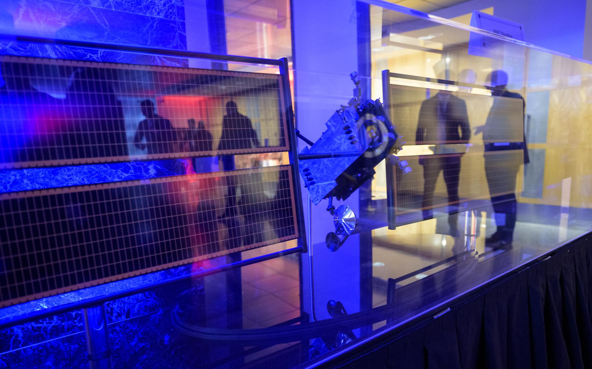
Engineers and technicians in a clean room at NASA's Jet Propulsion Laboratory in Southern California stand between the thick-walled aluminum vault and its duplicate (at rear) that they helped build for the agency's Europa Clipper spacecraft. As Europa Clipper orbits Jupiter, conducting flybys of its moon Europa to gather science data, the vault will protect the spacecraft's electronics from Jupiter's intense radiation. In 2022, the vault will be bolted to the top of Europa Clipper's propulsion module and affixed with cabling, to provide communications and control across the entire spacecraft. The duplicate test model of the vault gives engineers a way to test procedures before assembly of flight hardware. The test model also will be subjected to stress testing to confirm that the design will work when Europa Clipper operates in deep space. With an internal global ocean under a thick layer of ice, Europa may have the potential to harbor existing life. Europa Clipper will swoop around Jupiter on an elliptical path, dipping close to the moon on each flyby. Understanding Europa's habitability will help scientists better understand how life developed on Earth and the potential for finding life beyond our planet. Europa Clipper is set to launch in 2024. https://photojournal.jpl.nasa.gov/catalog/PIA24479
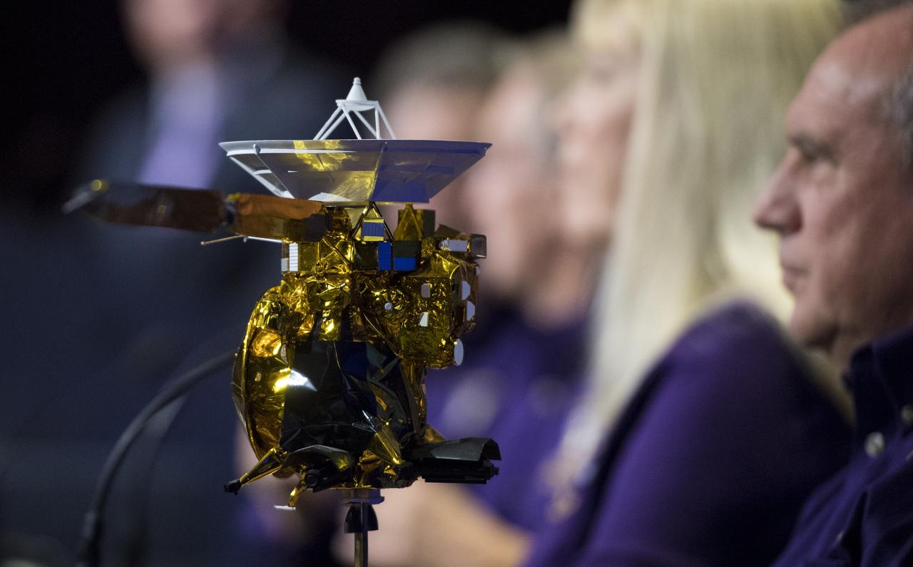
A model of the Cassini-Huygens spacecraft is seen during a press conference previewing Cassini's End of Mission, Wednesday, Sept. 13, 2017 at NASA's Jet Propulsion Laboratory in Pasadena, California. Since its arrival in 2004, the Cassini-Huygens mission has been a discovery machine, revolutionizing our knowledge of the Saturn system and captivating us with data and images never before obtained with such detail and clarity. On Sept. 15, 2017, operators will deliberately plunge the spacecraft into Saturn, as Cassini gathered science until the end. The “plunge” ensures Saturn’s moons will remain pristine for future exploration. During Cassini’s final days, mission team members from all around the world gathered at NASA’s Jet Propulsion Laboratory, Pasadena, California, to celebrate the achievements of this historic mission. Photo Credit: (NASA/Joel Kowsky)
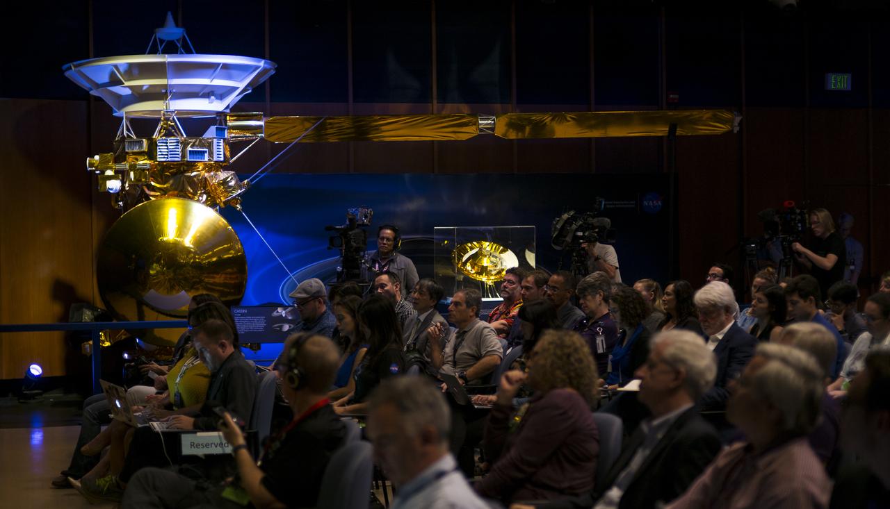
A model of the Cassini-Huygens spacecraft is seen in the von Kármán Auditorium during a press conference previewing Cassini's End of Mission, Wednesday, Sept. 13, 2017 at NASA's Jet Propulsion Laboratory in Pasadena, California. Since its arrival in 2004, the Cassini-Huygens mission has been a discovery machine, revolutionizing our knowledge of the Saturn system and captivating us with data and images never before obtained with such detail and clarity. On Sept. 15, 2017, operators will deliberately plunge the spacecraft into Saturn, as Cassini gathered science until the end. The “plunge” ensures Saturn’s moons will remain pristine for future exploration. During Cassini’s final days, mission team members from all around the world gathered at NASA’s Jet Propulsion Laboratory, Pasadena, California, to celebrate the achievements of this historic mission. Photo Credit: (NASA/Joel Kowsky)
The first prototype starshade developed by NASA's Jet Propulsion Laboratory, shown in technology partner Astro Aerospace/Northrup Grumman's facility in Santa Barbara, California, in 2013. As shown by this 66 foot (20-meter) model, starshades can come in many shapes and sizes. This design shows petals that are more extreme in shape which properly diffracts starlight for smaller telescopes. Each petal is covered in a high-performance plastic film that resembles gold foil. On a starshade ready for launch, the thermal gold foil will only cover the side of the petals facing away from the telescope, with black on the other, so as not to reflect other light sources such as the Earth into its camera. http://photojournal.jpl.nasa.gov/catalog/PIA20906
An engineer working on NASA's Mars 2020 mission uses a solar intensity probe to measure and compare the amount of artificial sunlight that reaches different portions of the rover. To simulate the Sun's rays for the test, powerful xenon lamps several floors below the chamber were illuminated, their light directed onto a mirror at the top of the chamber and reflected down on the spacecraft. The data collected during this test will be used to confirm thermal models the team has generated regarding how the Sun's rays will interact with the 2020 rover while on the surface of Mars. The image was taken on Oct. 14, 2019, in the Space Simulator Facility at NASA's Jet Propulsion Laboratory in Pasadena, California. https://photojournal.jpl.nasa.gov/catalog/PIA23469
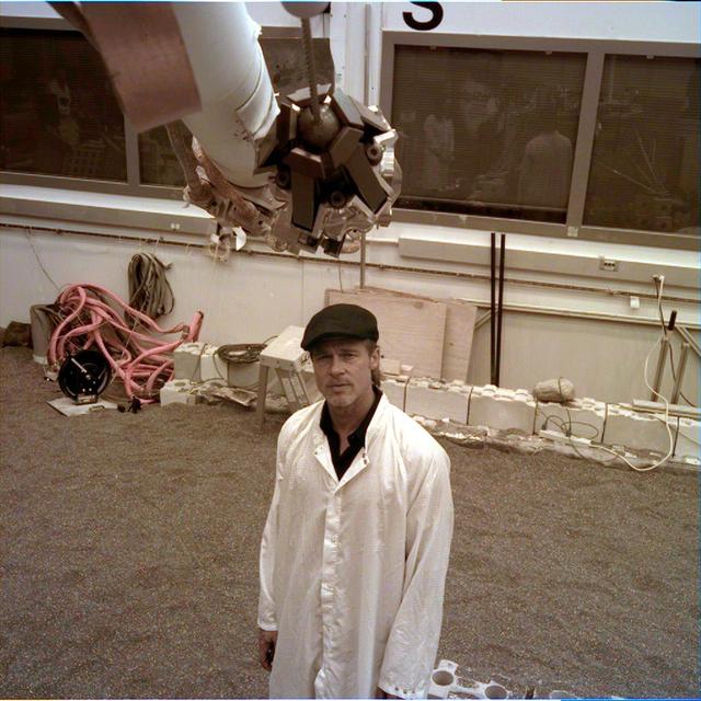
The engineering model of NASA's InSight lander — a replica used for test purposes — took an image of the actor Brad Pitt at NASA's Jet Propulsion Laboratory in Pasadena, California, on Sept. 6, 2019. Taken by the instrument deployment camera on the replica's robotic arm in the Mars-like environment of JPL's In-Situ Instrument Laboratory, the picture has been white-balanced to remove the orange-red tint of the Mars lights in the room. Pitt visited JPL to learn about real space technology after filming his space-themed movie "Ad Astra." https://photojournal.jpl.nasa.gov/catalog/PIA23280
John Grotzinger, Mars Science Laboratory (MSL) project scientist, Jet Propulsion Lab (JPL), Pasadena, Calif., holds up a model of the MSL, or Curiosity, at a press conference at the Smithsonian's National Air and Space Museum on Friday, July 22, 2011 in Washington. The MSL is scheduled to launch late this year from NASA's Kennedy Space Center in Florida and land in August 2012. Curiosity is twice as long and more than five times as heavy as previous Mars rovers. The rover will study whether the landing region at Gale crater had favorable environmental conditions for supporting microbial life and for preserving clues about whether life ever existed. Photo Credit: (NASA/Carla Cioffi)

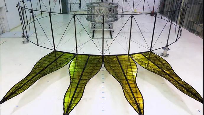
A deployed half-scale starshade with four petals at NASA's Jet Propulsion Laboratory, Pasadena, California, in 2014. The flower-like petals of the starshade are designed to diffract bright starlight away from telescopes seeking the dim light of exoplanets. The starshade was re-designed from earlier models to allow these petals to furl, or wrap around the spacecraft, for launch into space. Each petal is covered in a high-performance plastic film that resembles gold foil. On a starshade ready for launch, the thermal gold foil will only cover the side of the petals facing away from the telescope, with black on the other, so as not to reflect other light sources such as the Earth into its camera. http://photojournal.jpl.nasa.gov/catalog/PIA20904
This image shows the bare bones of the first prototype starshade by NASA's Jet Propulsion Laboratory, Pasadena, California. The prototype was shown in technology partner Astro Aerospace/Northrup Grumman's facility in Santa Barbara, California in 2013. In order for the petals of the starshade to diffract starlight away from the camera of a space telescope, they must be deployed with accuracy once the starshade reaches space. The four petals pictured in the image are being measured for this positional accuracy with a laser. As shown by this 66-foot (20-meter) model, starshades can come in many shapes and sizes. This design shows petals that are more extreme in shape which properly diffracts starlight for smaller telescopes. http://photojournal.jpl.nasa.gov/catalog/PIA20903

This close-up composite of images captured by NASA's Galileo spacecraft in the 1990s shows the crust of Jupiter's moon Europa. These are the kind of features studied by scientists who recently modeled how moonquakes may trigger landslides on icy moons circling Jupiter and Saturn. Visible here is a juxtaposition of features: possible fault scarps (like those found on Earth when tectonic activity breaks the crust) adjacent to smooth areas that may have been produced by landslide material. NASA's Jet Propulsion Laboratory in Southern California managed the mission for the agency. JPL is a division of Caltech in Pasadena, California. https://photojournal.jpl.nasa.gov/catalog/PIA25499
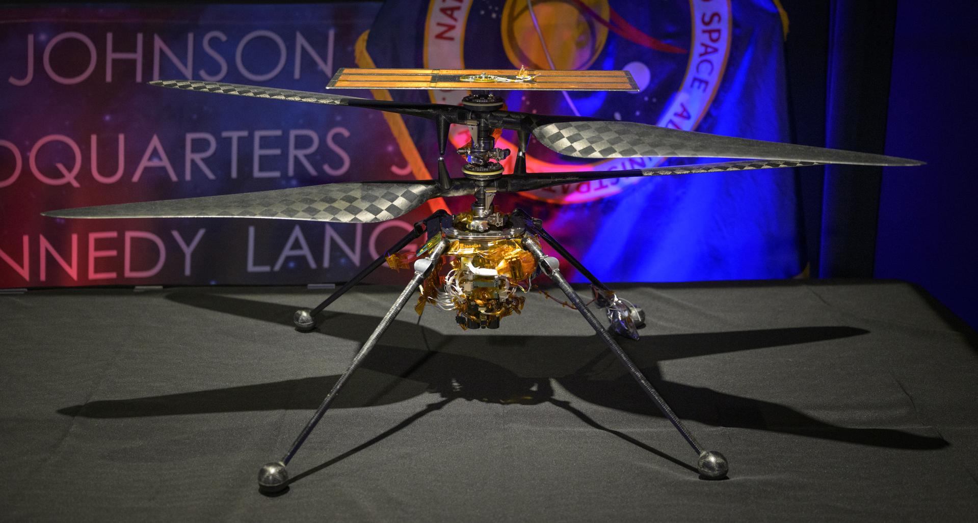
Ingenuity Mars Helicopter, Engineering Design Model 1, is seen on display during an event where NASA is outlining how the agency is executing President Donald J. Trump’s National Space Policy and accelerating preparations for America’s return to the surface of the Moon by 2028, Tuesday, March 24, 2026, at the Mary W. Jackson NASA Headquarters building in Washington. During the event NASA leadership provided updates on mission priorities, including sending the first astronauts to the lunar surface in more than 50 years, establishing the initial elements of a permanent lunar base, getting America underway in space on nuclear propulsion, and other objectives. Photo Credit: (NASA/Bill Ingalls)

A model of the Dragonfly rotorcraft is seen in the NASA Headquarters lobby ahead of an event where NASA outlined how the agency is executing President Donald J. Trump’s National Space Policy and accelerating preparations for America’s return to the surface of the Moon by 2028, Tuesday, March 24, 2026, at the Mary W. Jackson NASA Headquarters building in Washington. During the event NASA leadership provided updates on mission priorities, including sending the first astronauts to the lunar surface in more than 50 years, establishing the initial elements of a permanent lunar base, getting America underway in space on nuclear propulsion, and other objectives. Photo Credit: (NASA/Bill Ingalls)
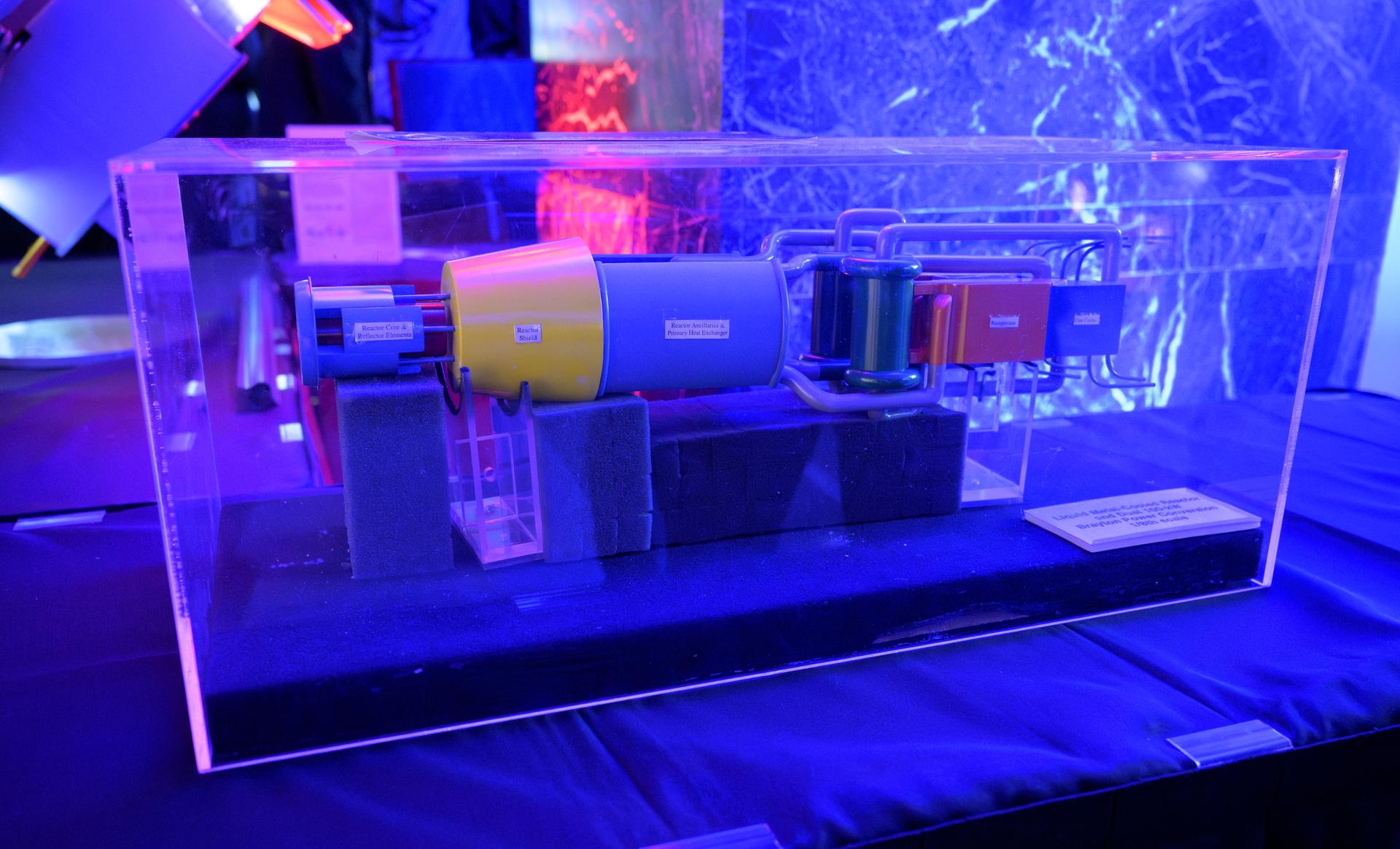
A model of a liquid metal-cooled reactor, dual 100-kw Brayton Power Conversion is seen on display during an event where NASA is outlining how the agency is executing President Donald J. Trump’s National Space Policy and accelerating preparations for America’s return to the surface of the Moon by 2028, Tuesday, March 24, 2026, at the Mary W. Jackson NASA Headquarters building in Washington. During the event NASA leadership provided updates on mission priorities, including sending the first astronauts to the lunar surface in more than 50 years, establishing the initial elements of a permanent lunar base, getting America underway in space on nuclear propulsion, and other objectives. Photo Credit: (NASA/Bill Ingalls)
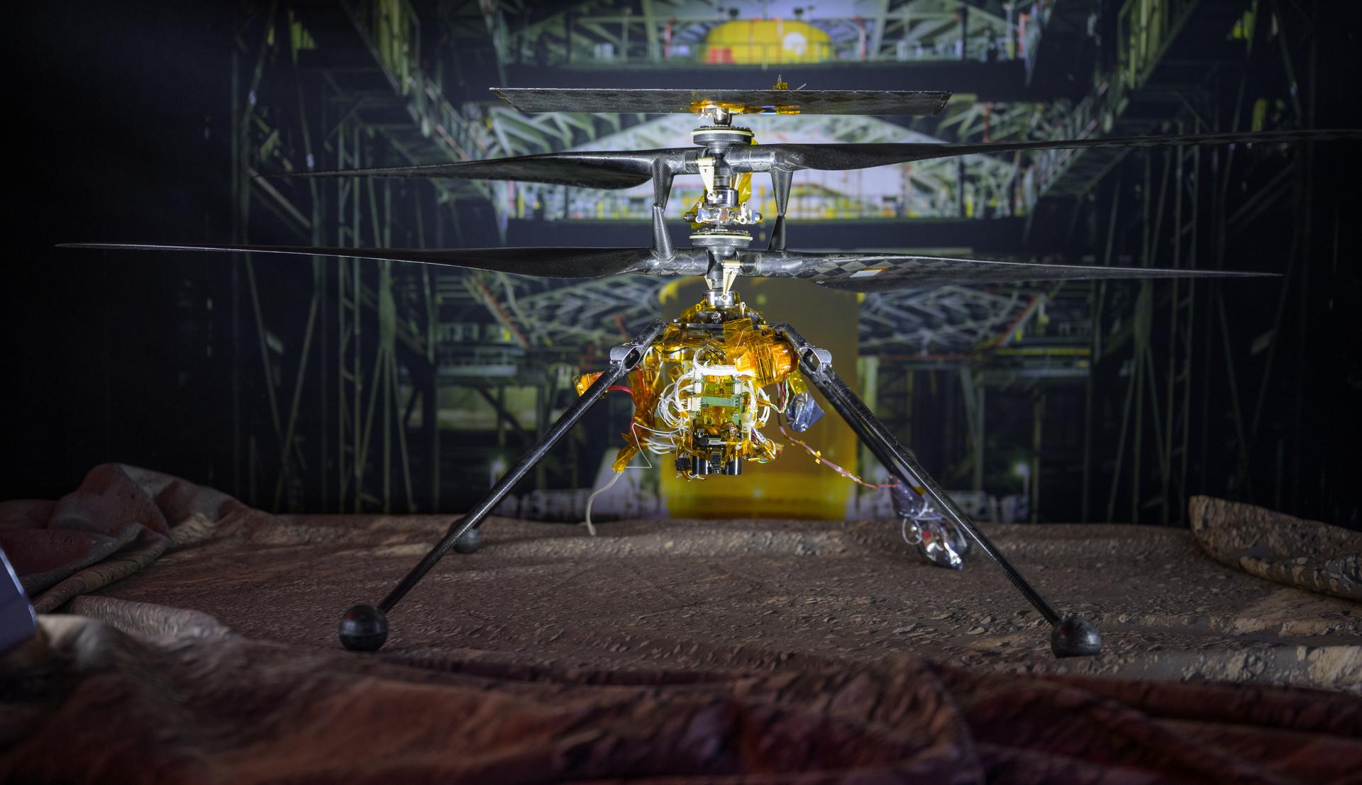
Ingenuity Mars Helicopter, Engineering Design Model 1, is seen on display during an event where NASA is outlining how the agency is executing President Donald J. Trump’s National Space Policy and accelerating preparations for America’s return to the surface of the Moon by 2028, Tuesday, March 24, 2026, at the Mary W. Jackson NASA Headquarters building in Washington. During the event NASA leadership provided updates on mission priorities, including sending the first astronauts to the lunar surface in more than 50 years, establishing the initial elements of a permanent lunar base, getting America underway in space on nuclear propulsion, and other objectives. Photo Credit: (NASA/Bill Ingalls)
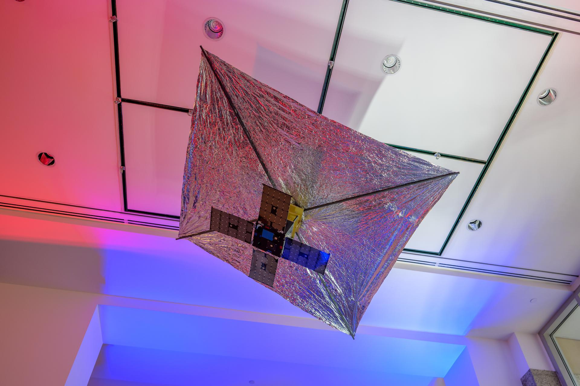
A model of the Advanced Composite Solar Sail System (ACS3) is seen in the NASA Headquarters lobby during a 2-day event where NASA outlined how the agency is executing President Donald J. Trump’s National Space Policy and accelerating preparations for America’s return to the surface of the Moon by 2028, Wednesday, March 25, 2026, at the Mary W. Jackson NASA Headquarters building in Washington. During the event NASA leadership provided updates on mission priorities, including sending the first astronauts to the lunar surface in more than 50 years, establishing the initial elements of a permanent lunar base, getting America underway in space on nuclear propulsion, and other objectives. Photo Credit: (NASA/Bill Ingalls)
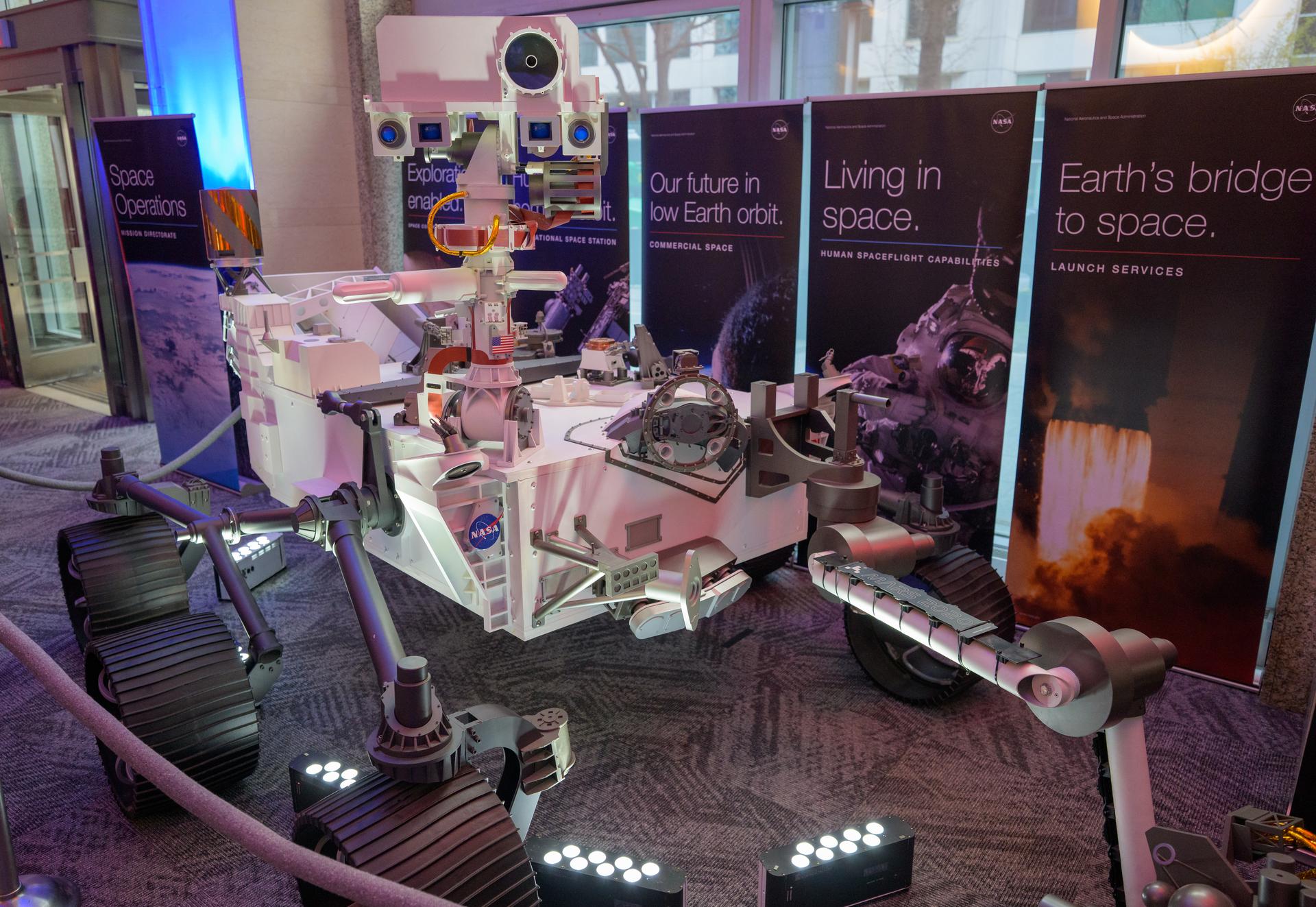
A model of the Mars 2020 Perseverance Rover is seen in the NASA Headquarters lobby during a 2-day event where NASA outlined how the agency is executing President Donald J. Trump’s National Space Policy and accelerating preparations for America’s return to the surface of the Moon by 2028, Wednesday, March 25, 2026, at the Mary W. Jackson NASA Headquarters building in Washington. During the event NASA leadership provided updates on mission priorities, including sending the first astronauts to the lunar surface in more than 50 years, establishing the initial elements of a permanent lunar base, getting America underway in space on nuclear propulsion, and other objectives. Photo Credit: (NASA/Bill Ingalls)
Steve Chesley, Stardust NExT co-investigator, the Jet Propulsion Laboratory, holds up a model of Comet Tempel 1 during a news briefing, Wednesday, Jan. 19, 2011, at NASA Headquarters in Washington. On Feb. 14, 2011 NASA's Stardust-NExT (New Exploration of Tempel 1) mission will encounter Comet Tempel 1, providing a unique opportunity to measure the dust properties which will also provide a comparison between two observations of a single comet, Tempel 1, taken before and after a single orbital pass around the sun. Photo Credit: (NASA/Paul E. Alers)
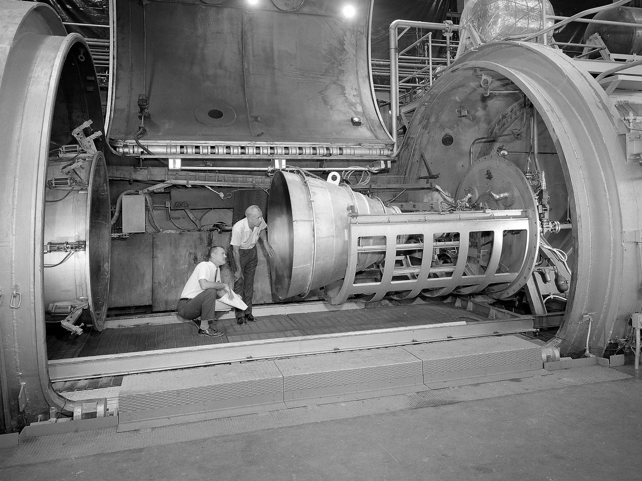
Bill Harrison and Bud Meilander check the setup of an Apollo Contour rocket nozzle in the Propulsion Systems Laboratory at the National Aeronautics and Space Administration (NASA) Lewis Research Center. The Propulsion Systems Laboratory contained two 14-foot diameter test chambers that could simulate conditions found at very high altitudes. The facility was used in the 1960s to study complex rocket engines such as the Pratt and Whitney RL-10 and rocket components such as the Apollo Contour nozzle, seen here. Meilander oversaw the facility’s mechanics and the installation of test articles into the chambers. Harrison was head of the Supersonic Tunnels Branch in the Test Installations Division. Researchers sought to determine the impulse value of the storable propellant mix, classify and improve the internal engine performance, and compare the results with analytical tools. A special setup was installed in the chamber that included a device to measure the thrust load and a calibration stand. Both cylindrical and conical combustion chambers were examined with the conical large area ratio nozzles. In addition, two contour nozzles were tested, one based on the Apollo Service Propulsion System and the other on the Air Force’s Titan transtage engine. Three types of injectors were investigated, including a Lewis-designed model that produced 98-percent efficiency. It was determined that combustion instability did not affect the nozzle performance. Although much valuable information was obtained during the tests, attempts to improve the engine performance were not successful.
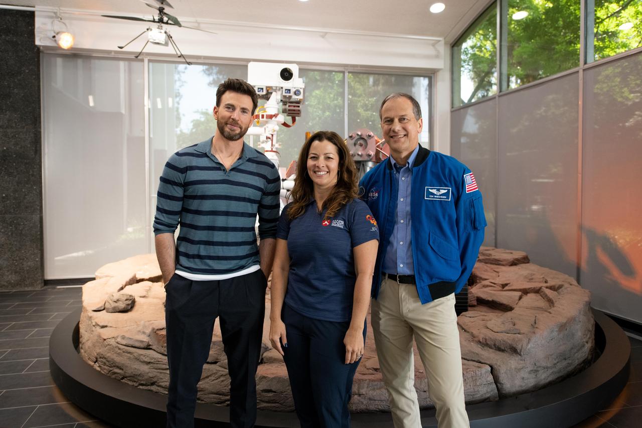
From left, actor Chris Evans, NASA's Perseverance Mars rover Surface Mission Manager Jessica Samuels, and NASA astronaut Tom Marshburn are seen in front of the rover model at the agency's Jet Propulsion Laboratory in Southern California on June 6, 2022. Evans visited JPL to learn more about space missions after starring as the lead voice in the space-themed movie "Lightyear." A key objective for Perseverance's mission on Mars is astrobiology, including the search for signs of ancient microbial life. The rover will characterize the planet's geology and past climate, pave the way for human exploration of the Red Planet, and be the first mission to collect and cache Martian rock and regolith (broken rock and dust). Subsequent NASA missions, in cooperation with ESA (European Space Agency), would send spacecraft to Mars to collect these sealed samples from the surface and return them to Earth for in-depth analysis. The Mars 2020 Perseverance mission is part of NASA's Moon to Mars exploration approach, which includes Artemis missions to the Moon that will help prepare for human exploration of the Red Planet. https://photojournal.jpl.nasa.gov/catalog/PIA25312

Mars Sample Return program manager, JPL, Bobby Braun, gives remarks during a NASA Perseverance rover press briefing about the search for ancient life at Mars and about samples to be brought back to Earth on a future mission, Wednesday, Feb. 17, 2021, at NASA's Jet Propulsion Laboratory in Pasadena, California. The Perseverance Mars rover is due to land on Mars Thursday, Feb. 18, 2021. A key objective for Perseverance’s mission on Mars is astrobiology, including the search for signs of ancient microbial life. The rover will characterize the planet’s geology and past climate, pave the way for human exploration of the Red Planet, and be the first mission to collect and cache Martian rock and regolith. Photo Credit: (NASA/Bill Ingalls)
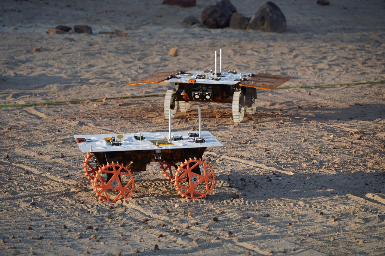
Two full-scale development model rovers that are part of NASA's CADRE (Cooperative Autonomous Distributed Robotic Exploration) technology demonstration drive in the Mars Yard at the agency's Jet Propulsion Laboratory in Southern California in August 2023. The project is designed to show that a group of robotic spacecraft can work together as a team to accomplish tasks and record data autonomously – without explicit commands from mission controllers on Earth. The rovers being tested here are similar in size and appearance to the flight models – still being built at the time of this image – that will travel to the Moon. Equipped with flight software and autonomy capabilities, these development models were used for drive tests outside the clean room. In this image, one rover is fitted with a stand-in for solar panels, while the other rover is not. A series of Mars Yard tests with the development models confirmed CADRE hardware and software can work together to accomplish key goals for the project. The rovers drove together in formation. Faced with unexpected obstacles in the way, they adjusted their plans as a group by sharing updated maps and replanning coordinated paths. And when one rover was low on battery charge, the whole team paused so they could later continue together. Several drives were performed at night under large flood lamps so the rovers could experience extreme shadows and lighting that approximate what they'll encounter during the lunar daytime. https://photojournal.jpl.nasa.gov/catalog/PIA26168

The PREFIRE (Polar Radiant Energy in the Far-InfraRed Experiment) mission will send two CubeSats – shown as an artist's concept against an image of Earth from orbit – into space to study how much heat the planet absorbs and emits from its polar regions, including the Arctic and Antarctica. Analysis of PREFIRE measurements will inform climate and ice models, providing better projections of how a warming world will affect sea ice loss, ice sheet melt, and sea level rise. Improving climate models can ultimately help to provide more accurate projections on the impacts of storm severity and frequency, as well as coastal erosion and flooding. The mission consists of two 6U CubeSats with a baseline mission length of 10 months and is jointly developed by NASA and the University of Wisconsin-Madison. NASA's Jet Propulsion Laboratory in Southern California manages the mission for the agency's Science Mission Directorate and is providing the instruments. Blue Canyon Technologies is building the CubeSats, and the University of Wisconsin-Madison will process the data collected by the instruments. The science team includes members from JPL and the Universities of Wisconsin, Michigan, and Colorado. https://photojournal.jpl.nasa.gov/catalog/PIA25778
An apprentice at the National Advisory Committee for Aeronautics (NACA) Lewis Flight Propulsion Laboratory shown training on the altitude supply air systems in the Engine Research Building. An ongoing four-year apprentice program was established at the laboratory in 1949 to facilitate the close interaction of the lab’s engineers, mechanics, technicians, and scientists. The apprentice school covered a variety of trades including aircraft mechanic, electronics instrumentation, machinist, and altitude systems mechanic, seen in this photograph. The apprentices rotated through the various shops and facilities to provide them with a well-rounded understanding of the work at the lab. The specialized skills required meant that NACA apprentices were held to a higher standard than those in industry. They had to pass written civil service exams before entering the program. Previous experience with mechanical model airplanes, radio transmission, six months of work experience, or one year of trade school was required. The Lewis program was certified by both the Department of Labor and the State of Ohio. One hundred fifty of the 2,000 hours of annual training were spent in the classroom. The remainder was devoted to study of models and hands-on work in the facilities. Examinations were coupled with evaluation by supervisors in the shops. The apprentices were promoted through a series of grades until they reached journeyman status. Those who excelled in the Apprentice Program would be considered for a separate five-year engineering draftsman program.
A model of the General Dynamics YF-16 Fighting Falcon in the test section of the 8- by 6-Foot Supersonic Wind Tunnel at the National Aeronautics and Space Administration (NASA) Lewis Research Center. The YF-16 was General Dynamics response to the military’s 1972 request for proposals to design a new 20,000-pound fighter jet with exceptional acceleration, turn rate, and range. The aircraft included innovative design elements to help pilots survive turns up to 9Gs, a new frameless bubble canopy, and a Pratt and Whitney 24,000-pound thrust F-100 engine. The YF-16 made its initial flight in February 1974, just six weeks before this photograph, at Edwards Air Force Base. Less than a year later, the Air Force ordered 650 of the aircraft, designated as F-16 Fighting Falcons. The March and April 1974 tests in the 8- by 6-foot tunnel analyzed the aircraft’s fixed-shroud ejector nozzle. The fixed-nozzle area limited drag, but also limited the nozzle’s internal performance. NASA researchers identified and assessed aerodynamic and aerodynamic-propulsion interaction uncertainties associated the prototype concept. YF-16 models were also tested extensively in the 11- by 11-Foot Transonic Wind Tunnel and 9- by 7-Foot Supersonic Wind Tunnel at Ames Research Center and the 12-Foot Pressure Wind Tunnel at Langley Research Center.

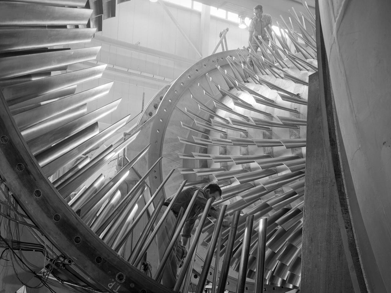
A mechanic and apprentice work on a wooden impeller in the Fabrication Shop at the NACA Lewis Flight Propulsion Laboratory. The 260-person Fabrication Division created almost all of the equipment and models used at the laboratory. The Technical Services Building, referred to as the “Fab Shop”, contained a number of specialized shops in the 1940s and 1950s. These included a Machine Shop, Sheet Metal Shop, Wood and Pattern Shop, Instrument Shop, Thermocouple Shop, Heat Treating Shop, Metallurgical Laboratory, and Fabrication Office. The Machine Shop fabricated research equipment not commercially available. During World War II these technicians produced high-speed cameras for combustion research, impellers and other supercharger components, and key equipment for the lab’s first supersonic wind tunnel. The Wood and Pattern Shop created everything from control panels and cabinets to aircraft model molds for sheet metal work. The Sheet Metal Shop had the ability to work with 0.01 to 4-inches thick steel plates. The Instrument Shop specialized in miniature parts and instrumentation, while the Thermocouple Shop standardized the installation of pitot tubes and thermocouples. The Metallurgical Laboratory contained a control lab for the Heat Treating Shop and a service lab for the NACA Lewis research divisions. The Heat Treating Shop heated metal parts to optimize their physical properties and contained a Precision Castings Foundry to manufacture equipment made of heat resisting alloys.

Jet Propulsion Laboratory (JPL) technicians finish mounting a thermal model of a radioisotope thermoelectric generator (RTG) on the installation cart which will be used to install the RTG in the Cassini spacecraft at Level 14 of Space Launch Complex 40, Cape Canaveral Air Station. The technicians use the thermal model to practice installation procedures. The three actual RTGs which will provide electrical power to Cassini on its 6.7-mile trip to the Saturnian system, and during its four-year mission at Saturn, are being tested and monitored in the Radioisotope Thermoelectric Generator Storage Building in KSC's Industrial Area. The RTGs use heat from the natural decay of plutonium to generate electric power. RTGs enable spacecraft to operate far from the Sun where solar power systems are not feasible. The RTGs on Cassini are of the same design as those flying on the already deployed Galileo and Ulysses spacecraft. The Cassini mission is targeted for an October 6 launch aboard a Titan IVB/Centaur expendable launch vehicle. Cassini is built and managed for NASA by JPL
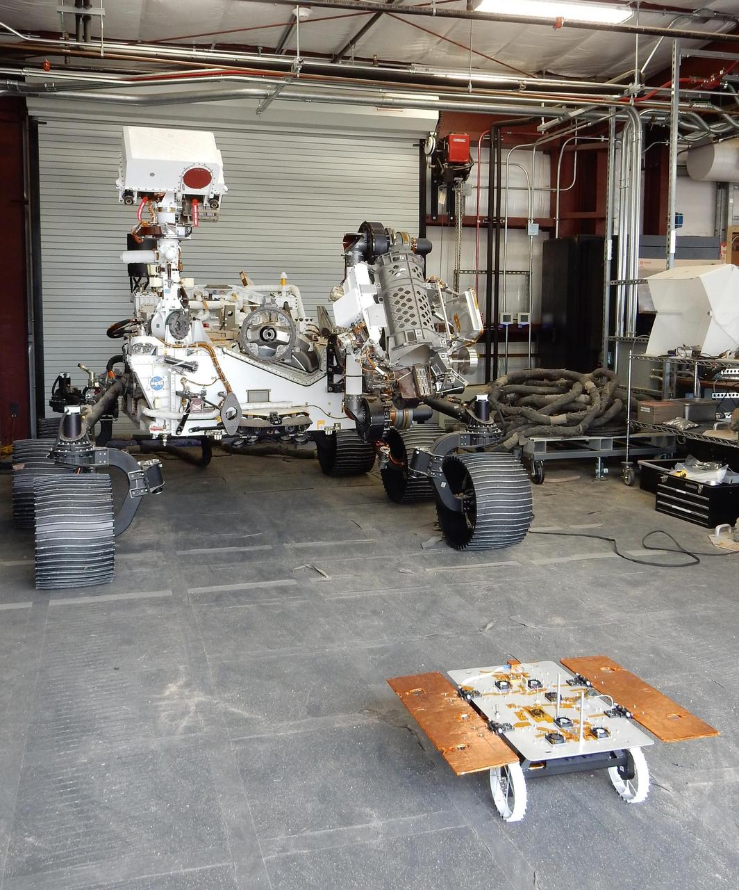
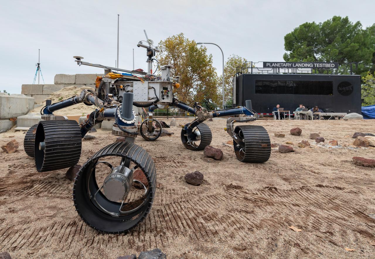
The Earth-bound full-scale engineering model of NASA's Perseverance rover, called OPTIMISM, seems to peer down at a much smaller CADRE rover in a building in the Mars Yard at NASA's Jet Propulsion Laboratory in Southern California in June 2023. Short for Cooperative Autonomous Distributed Robotic Exploration, NASA's CADRE technology demonstration is slated to arrive at the Moon in spring 2024 as part of the agency's CLPS (Commercial Lunar Payload Services) initiative. CADRE is designed to demonstrate that multiple robots can cooperate and explore together autonomously – without direct input from human mission controllers. The development rover being tested is similar in size and appearance to the flight models of the CADRE rovers, which are still being built. A trio of the miniature solar-powered rovers, each about the size of a carry-on suitcase, will explore the Moon as a team, communicating via radio with each other and a base station aboard a lunar lander. By taking simultaneous measurements from multiple locations, CADRE will also demonstrate how multirobot missions can record data impossible for a single robot to achieve – a tantalizing prospect for future missions. https://photojournal.jpl.nasa.gov/catalog/PIA25668
Engineers practice deploying InSight's instruments in a lab at NASA's Jet Propulsion Laboratory in Pasadena, California. Several of them are wearing sunglasses to block the bright yellow lights in the test space, which mimic sunlight as it appears on Mars. The yellow lights are used to test cameras which are the same as those used by InSight on Mars. The entire lab space in the center of the image has been sculpted to mimic the terrain in front of the lander on Mars, creating more reliable test conditions. The area in the center of the image is the "workspace" where the lander's instruments can be set down; wood blocks have been laid down to mark the perimeter of these areas. Rocks have been chosen to match the size, shape and location of those in front of InSight on Mars. In the center of the image is a model of the lander's copper-colored seismometer; at the bottom-right is a second model of the seismometer used for a different kind of testing. In the lower left corner of the image is a bag of crushed granite, which is used in this lab to simulate Martian sand. https://photojournal.jpl.nasa.gov/catalog/PIA22744

A development model rover that is part of NASA's CADRE (Cooperative Autonomous Distributed Robotic Exploration) technology demonstration took its first autonomous drive around the Mars Yard at the agency's Jet Propulsion Laboratory in Southern California in June 2023. The CADRE team tested a new wheel design, surface navigation software, and mobility capabilities, among other aspects of the project. Engineer Kristopher Sherrill is shown recording video of the test. The rover being tested is similar in size and appearance to the flight models of the CADRE rovers, which are still being built. Slated to arrive at the Moon in spring 2024 as part of NASA's CLPS (Commercial Lunar Payload Services) initiative, CADRE is designed to demonstrate that multiple robots can cooperate and explore together autonomously – without direct input from human mission controllers. A trio of the miniature solar-powered rovers, each about the size of a carry-on suitcase, will explore the Moon as a team, communicating via radio with each other and a base station aboard a lunar lander. By taking simultaneous measurements from multiple locations, CADRE will also demonstrate how multirobot missions can record data impossible for a single robot to achieve – a tantalizing prospect for future missions. Movie available at https://photojournal.jpl.nasa.gov/catalog/PIA25665
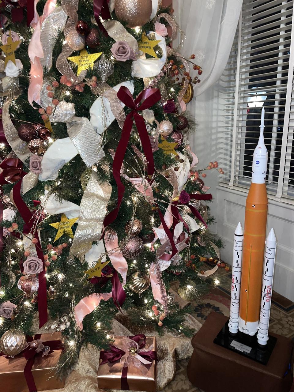
A model of NASA’s SLS (Space Launch System) rocket is part of the holiday display in the Mississippi Governor’s Mansion in Jackson, the official residence of state Gov. Tate Reeves. The model symbolizes the longtime relationship and shared history between the state of Mississippi and NASA’s Stennis Space Center near Bay St. Louis, Mississippi, the nation’s largest rocket propulsion test site. Built in the 1960s, NASA Stennis tested Apollo rocket stages that carried humans to the Moon and every main engine that helped launch 135 space shuttle missions. It now is testing engines and systems for NASA’s Artemis missions and operates as a powerful aerospace and technology hub for the region and state. “We are grateful for our ongoing relationship with the state of Mississippi,” NASA Stennis Director John Bailey said. “We appreciate every opportunity to highlight the role NASA Stennis and the state play in helping to power the nation’s human space exploration program. We look forward to 2025 and continuing our work to test engines and systems that will help launch Artemis missions back to the Moon and beyond.”
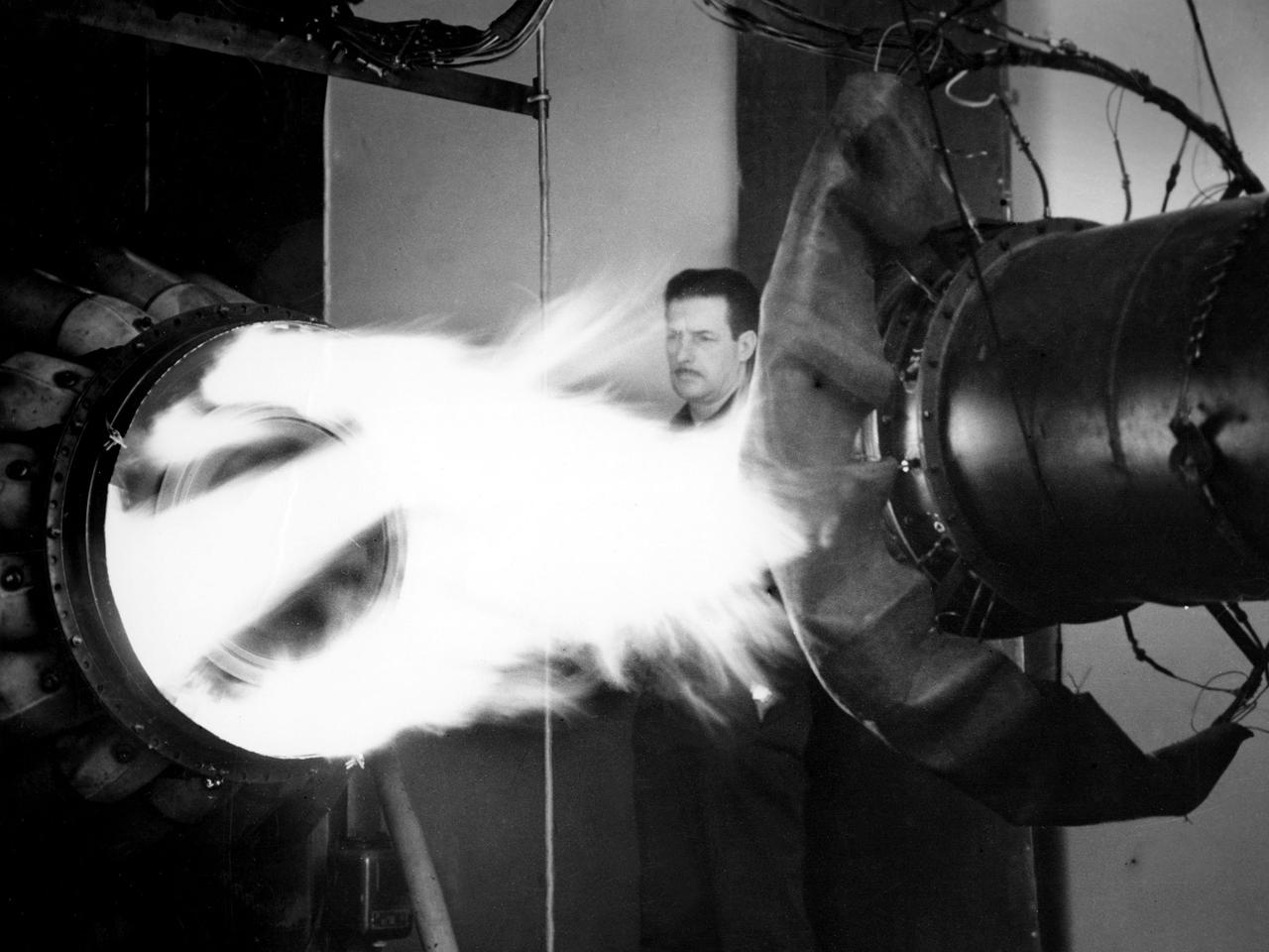
A mechanic watches the firing of a General Electric I-40 turbojet at the National Advisory Committee for Aeronautics (NACA) Lewis Flight Propulsion Laboratory. The military selected General Electric’s West Lynn facility in 1941 to secretly replicate the centrifugal turbojet engine designed by British engineer Frank Whittle. General Electric’s first attempt, the I-A, was fraught with problems. The design was improved somewhat with the subsequent I-16 engine. It was not until the engine's next reincarnation as the I-40 in 1943 that General Electric’s efforts paid off. The 4000-pound thrust I-40 was incorporated into the Lockheed Shooting Star airframe and successfully flown in June 1944. The Shooting Star became the US’s first successful jet aircraft and the first US aircraft to reach 500 miles per hour. NACA Lewis studied all of General Electric’s centrifugal turbojet models during the 1940s. In 1945 the entire Shooting Star aircraft was investigated in the Altitude Wind Tunnel. Engine compressor performance and augmentation by water injection; comparison of different fuel blends in a single combustor; and air-cooled rotors were studied. The mechanic in this photograph watches the firing of a full-scale I-40 in the Jet Propulsion Static Laboratory. The facility was quickly built in 1943 specifically in order to test the early General Electric turbojets. The I-A was secretly analyzed in the facility during the fall of 1943.
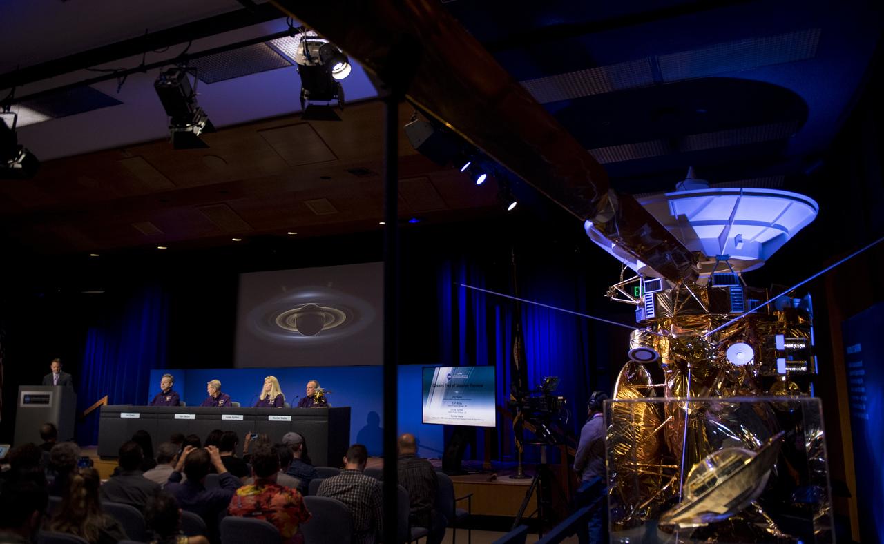
A model of the Cassini spacecraft is seen during a press conference previewing Cassini's End of Mission, Wednesday, Sept. 13, 2017 at NASA's Jet Propulsion Laboratory in Pasadena, California. Participants in the press conference were: Director of NASA's Planetary Science Division, Jim Green, left, Cassini program manager at JPL, Earl Maize, second from right, Cassini project scientist at JPL, Linda Spilker, second from right, and principle investigator for the Neutral Mass Spectrometer (INMS) at the Southwest Research Institute, Hunter Waite, right. Since its arrival in 2004, the Cassini-Huygens mission has been a discovery machine, revolutionizing our knowledge of the Saturn system and captivating us with data and images never before obtained with such detail and clarity. On Sept. 15, 2017, operators will deliberately plunge the spacecraft into Saturn, as Cassini gathered science until the end. The “plunge” ensures Saturn’s moons will remain pristine for future exploration. During Cassini’s final days, mission team members from all around the world gathered at NASA’s Jet Propulsion Laboratory, Pasadena, California, to celebrate the achievements of this historic mission. Photo Credit: (NASA/Joel Kowsky)
Each year, the NESC produces the NESC Technical Update, which highlights two or three individuals from each Center and includes assessments throughout the year. Because of the critical contributions to the NESC mission this year, Rob Jankovsky, NESC Chief Engineer at GRC, chose two individuals to be highlighted. This year, it is Andrew Ring and Michael Cooper. The Lead Analyst for GRC’s Chemical and Thermal Propulsion Systems branch, Mr. Michael Cooper, is supporting NESC test operations on reaction control system thrusters for Gateway’s Power & Propulsion Element. “These thrusters are small with few moving parts, but the heat and mass transfers involved are very complex,” he said. The test campaign is putting the thrusters through a rigorous profile to simulate the lifetime they will experience over decades in space. Mr. Cooper is analyzing test data gathered on chamber pressure, temperature, flow rates, and more to develop models on thruster performance. He also built the tool that read in that data from the test stand instrumentation. Photo Credit: (NASA/Sara Lowthian-Hanna)