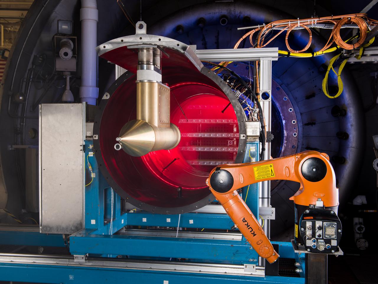
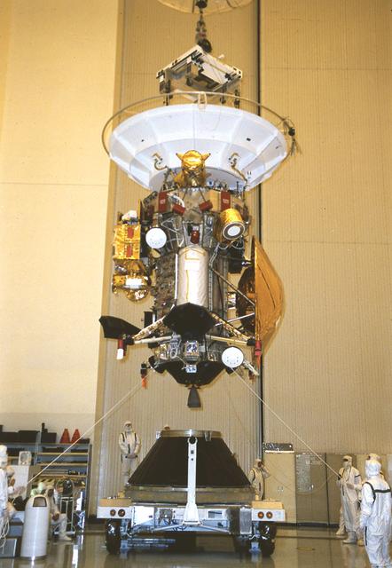
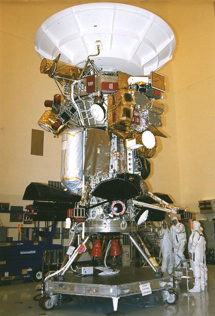
NASA Glenn’s Propulsion Systems Lab (PSL) is conducting research to characterize ice crystal clouds that can create a hazard to aircraft engines in certain conditions. With specialized equipment, scientists can create a simulated ice crystal cloud with the set of bars in the back spraying out a mist. The red area includes lasers, which measure the intensity of the cloud and a series of probes to measure everything from humidity to air pressure. The isokinetic probe (in gold) samples particles and the robotic arm (in orange) has a test tube on the end that catches ice particles for further measuring. NASA Glenn’s PSL is the only place in the world which can create these kind of ice crystal cloud conditions.
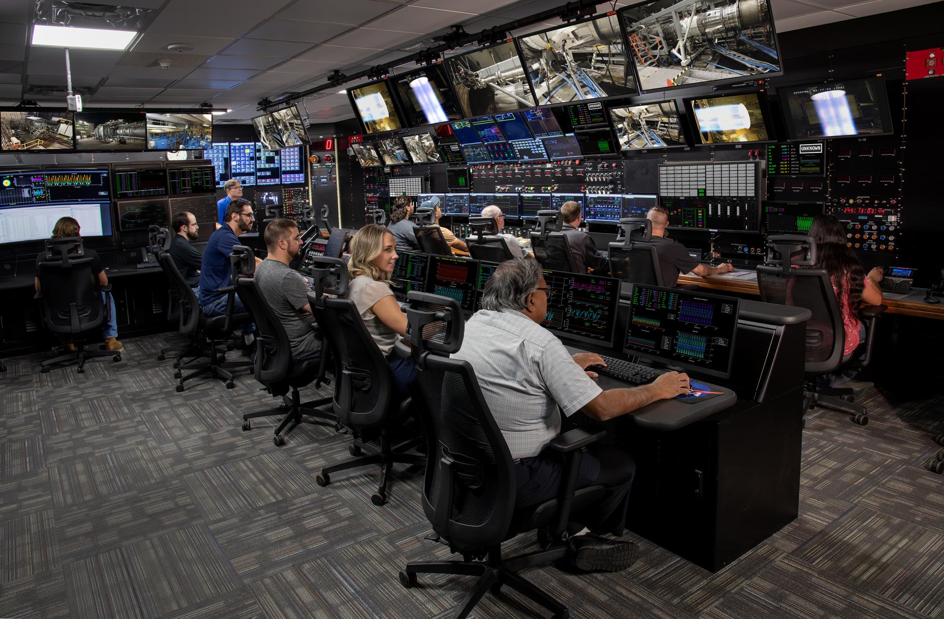
NASA GRC PSL, Propulsion System Lab, control room with operations personnel
Gunnar Kadlic monitors the data system in the NASA Glenn's Propulsion System Lab (PSL) recently remodeled control room. This is where jet and rocket engines are tested at GRC. This re-modeled control room offers better test monitoring and work stations for test engineers and technicians.
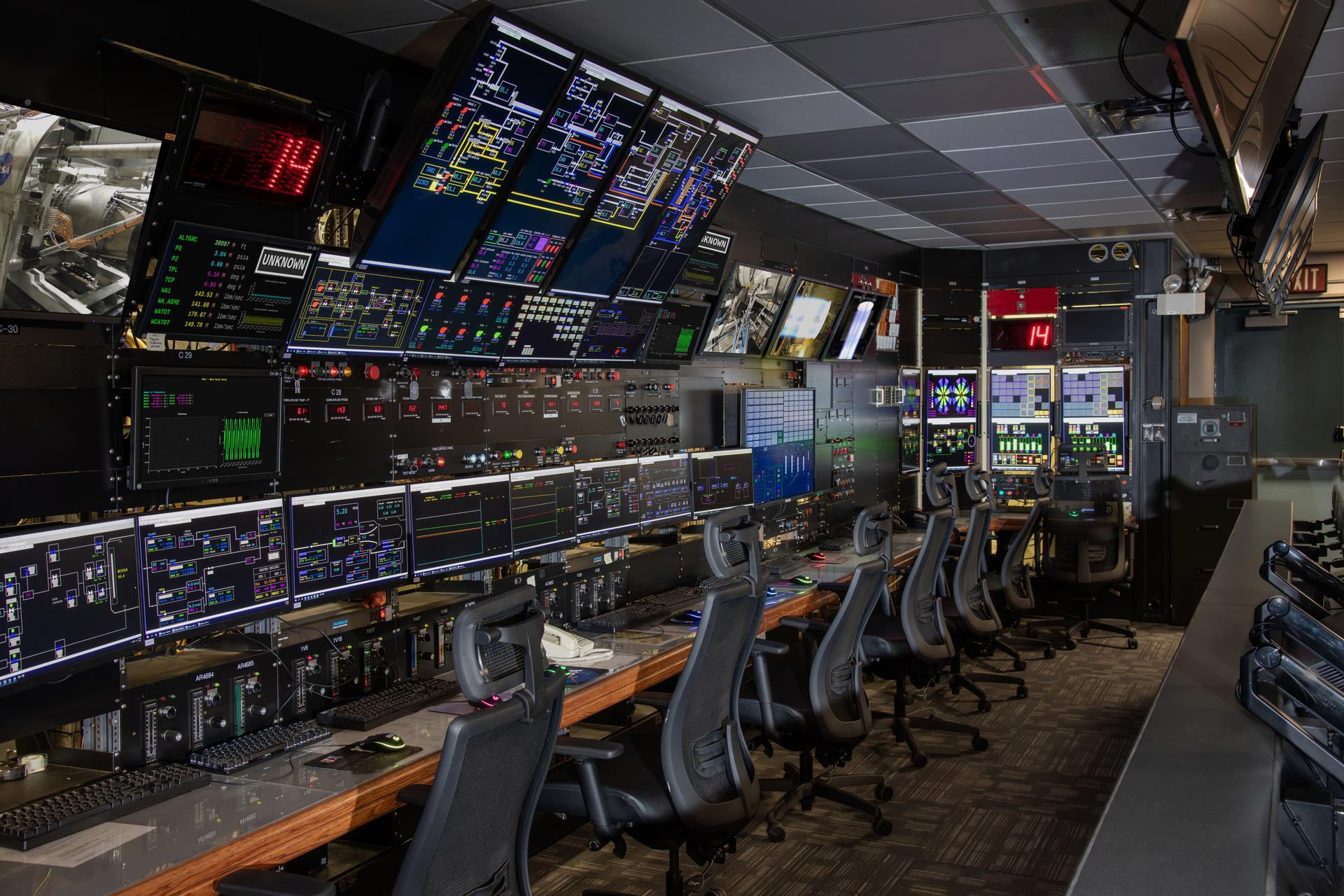
The Central Processing System at Glenn Research Center controls operations in the wind tunnels, propulsion systems lab, engine components research lab, and compressor, turbine and combustor test cells. Documentation photos of the facility were taken on December 19, 2023. Photo Credit: (NASA/Sara Lowthian-Hanna)
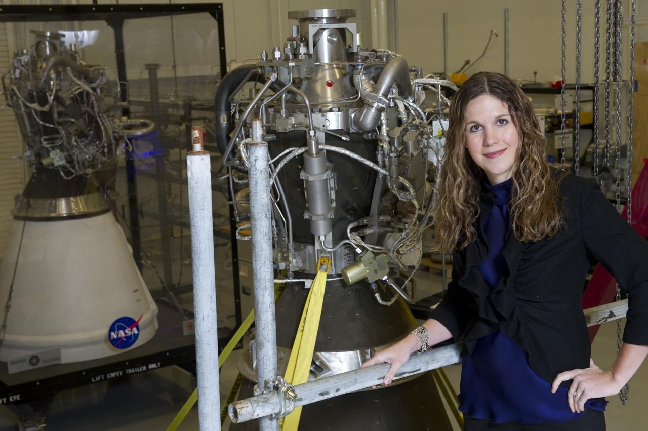
PROPULSION SYSTEMS ENGINEER ERIN BETTS IN MSFC PROPULSION ENGINEERING LAB
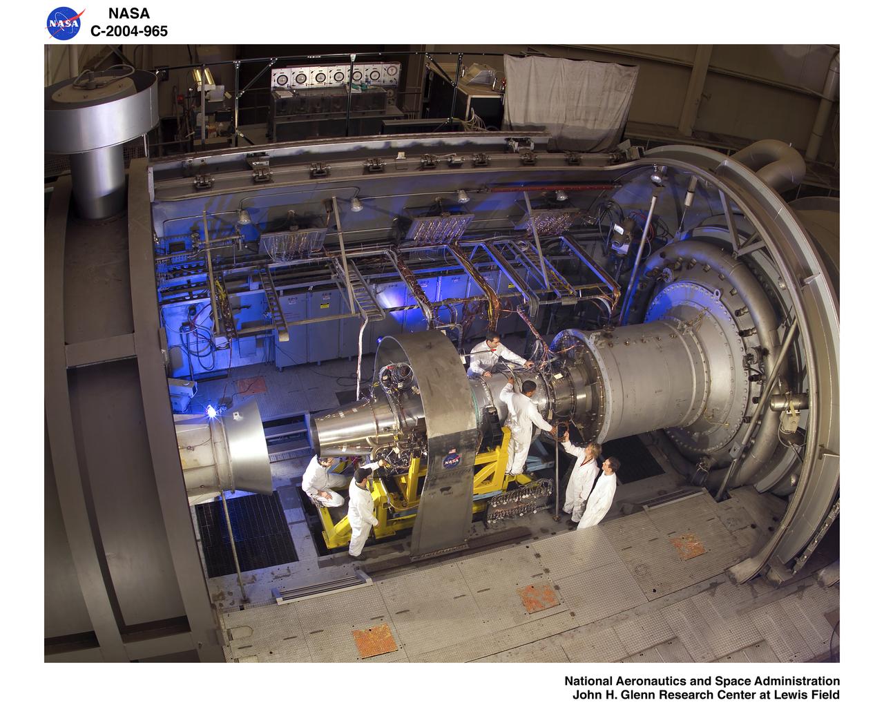
Jet engine being set up for testing with technicians from Propulsion System lab PSL
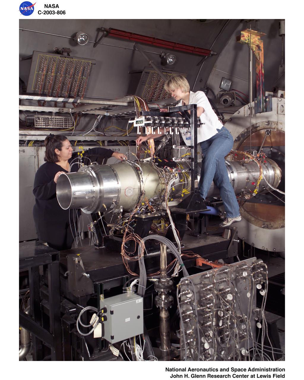
WILLIAMS INTERNATIONAL FJ33 TURBOFAN JET ENGINE TEST IN THE PROPULSION SYSTEMS LAB - PSL - CELL 4
The CPS controls operations used by Glenn Research Center's wind tunnels, propulsion systems lab, engine components research lab, and compressor, turbine and combustor test cells. Used widely throughout the lab, it operates equipment such as exhausters, chillers, cooling towers, compressors, dehydrators, and other such equipment.
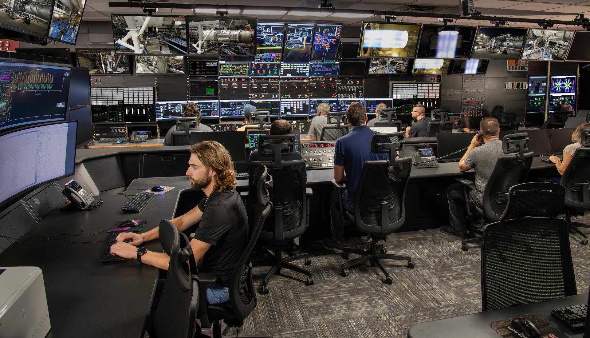
The NASA Glenn's Propulsion System Lab (PSL) recently remodeled control room. This is where jet and rocket engines are tested at GRC. This remodeled control room offers better test monitoring and work stations for test engineers and technicians.
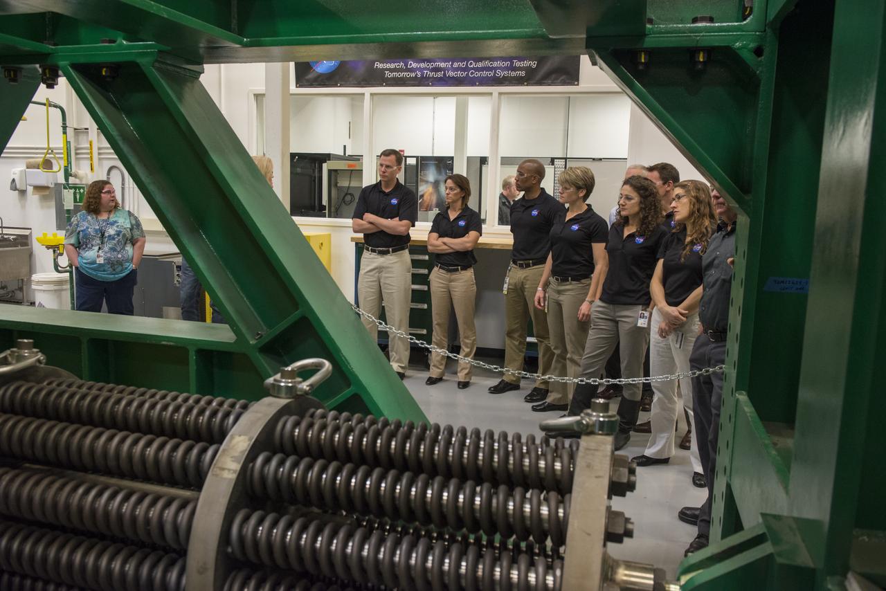
THE 2013 ASTRONAUT CANDIDATE CLASS VISITED THE THRUST VECTOR CONTROL TEST LAB AT MARSHALL'S PROPULSION RESEARCH DEVELOPMENT LABORATORY WHERE ENGINEERS ARE DEVELOPING AND TESTING THE SPACE LAUNCH SYSTEM'S GUIDANCE, NAVIGATION AND CONTROL SOFTWARE AND AVIONICS HARDWARE.

NASA Glenn’s Propulsion Systems Lab (PSL) is conducting research to characterize ice crystal clouds that can create a hazard to aircraft engines under certain conditions. The isokinetic probe (in gold) samples particles and another series of probes can measure everything from humidity to air pressure.
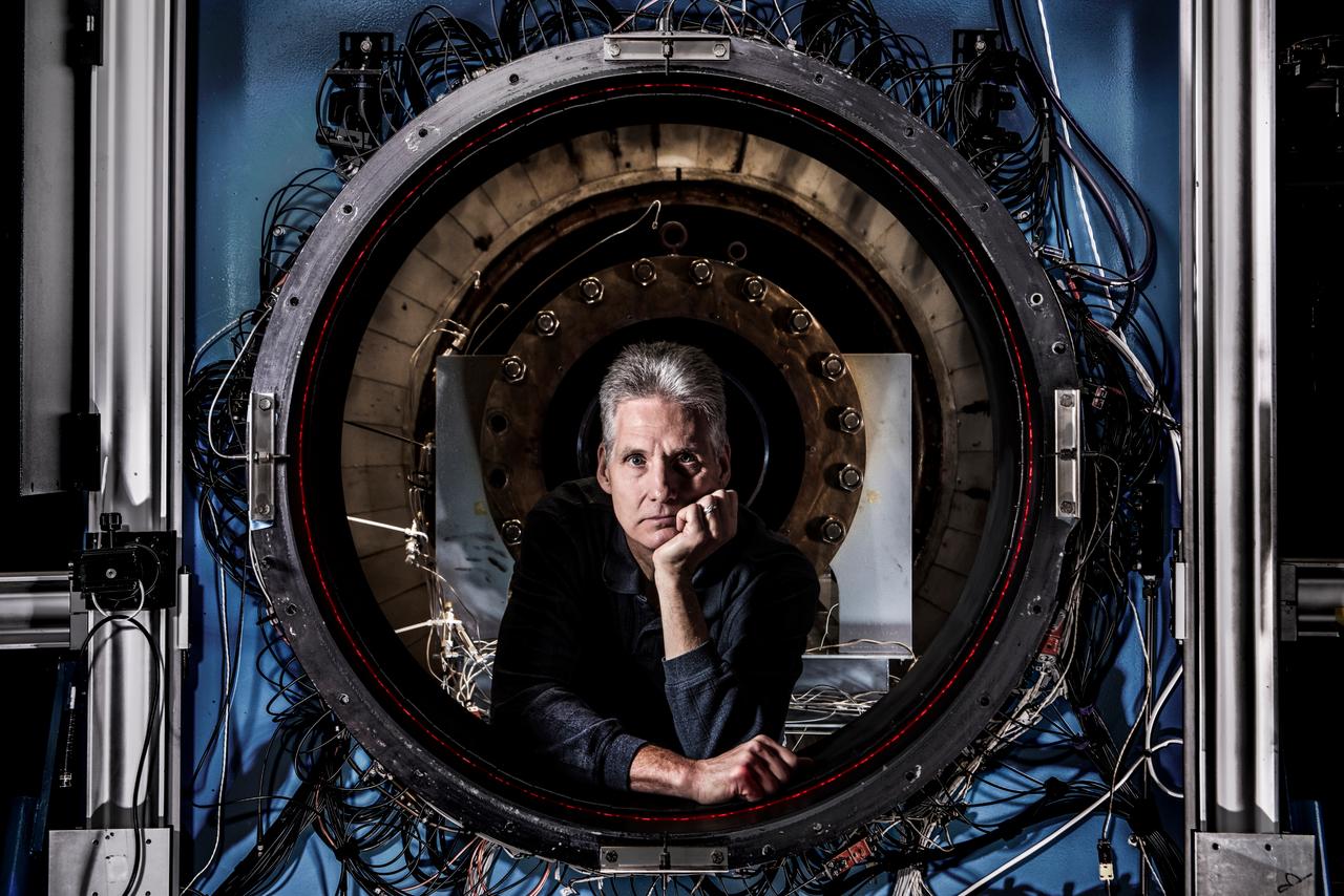
How do you measure a cloud? Tim Bencic does it with lasers. The NASA Glenn engineer invented a tomography system for our Propulsion Systems Lab to help understand the dangers of ice crystal icing on airplanes. Bencic’s system, affectionally called “Tim-ography” is like a CAT Scan. The laser light within its circular geometry bounces off the surface of ice particles in the cloud and fiber optic detectors map out its properties. This tool is helping NASA’s researchers make aircraft safer in challenging weather conditions.
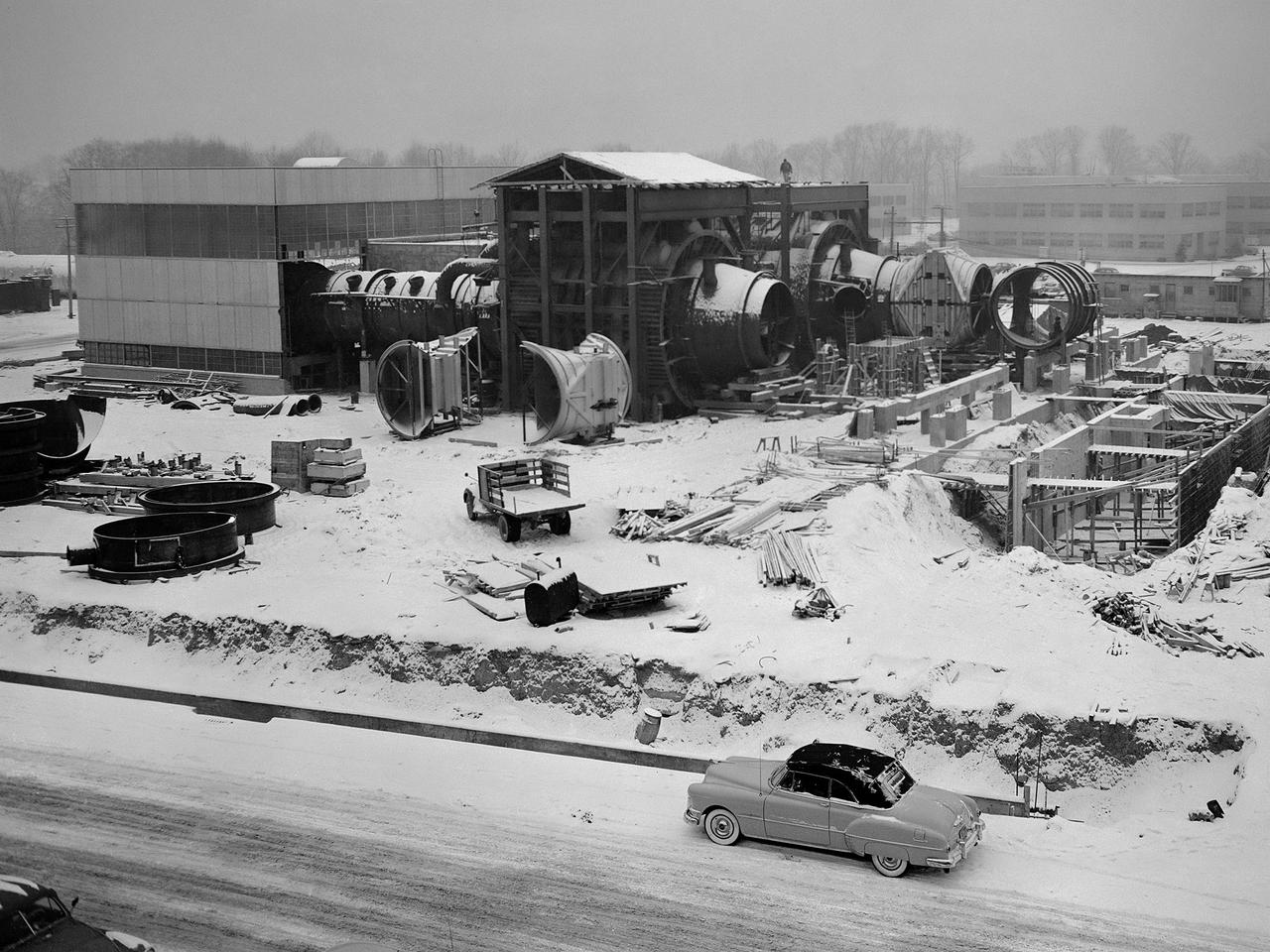
Construction of the Propulsion Systems Laboratory No. 1 and 2 at the National Advisory Committee for Aeronautics (NACA) Lewis Flight Propulsion Laboratory. When it began operation in late 1952, the Propulsion Systems Laboratory was the NACA’s most powerful facility for testing full-scale engines at simulated flight altitudes. The facility contained two altitude simulating test chambers which were a technological combination of the static sea-level test stands and the complex Altitude Wind Tunnel, which recreated actual flight conditions on a larger scale. NACA Lewis began designing the new facility in 1947 as part of a comprehensive plan to improve the altitude testing capabilities across the lab. The exhaust, refrigeration, and combustion air systems from all the major test facilities were linked. In this way, different facilities could be used to complement the capabilities of one another. Propulsion Systems Laboratory construction began in late summer 1949 with the installation of an overhead exhaust pipe connecting the facility to the Altitude Wind Tunnel and Engine Research Building. The large test section pieces arriving in early 1951, when this photograph was taken. The two primary coolers for the altitude exhaust are in place within the framework near the center of the photograph.

In a clean room at NASA's Jet Propulsion Laboratory in Southern California in October 2023, scientist Vanessa Bailey stands behind the Roman Coronagraph, which has been undergoing testing at the lab. Designed to block starlight and allow scientists to see the faint light from planets outside our solar system, the Coronagraph is a technology demonstration that will be part of NASA's Nancy Grace Roman Space Telescope. https://photojournal.jpl.nasa.gov/catalog/PIA26272
Jet Propulsion Research Lab (JPL) workers use a borescope to verify the pressure relief device bellow's integrity on a radioisotope thermoelectric generator (RTG) that has been installed on the Cassini spacecraft in the Payload Hazardous Servicing Facility. The activity is part of the mechanical and electrical verification testing of RTGs during prelaunch processing. RTGs use heat from the natural decay of plutonium to generate electrical power. The three RTGs on Cassini will enable the spacecraft to operate far from the Sun where solar power systems are not feasible. They will provide electrical power to Cassini on it seven year trip to the Saturnian system and during its four year mission at Saturn.
Jet Propulsion Research Lab (JPL) workers use a borescope to verify the pressure relief device bellow's integrity on a radioisotope thermoelectric generator (RTG) that has been installed on the Cassini spacecraft in the Payload Hazardous Servicing Facility. The activity is part of the mechanical and electrical verification testing of RTGs during prelaunch processing. RTGs use heat from the natural decay of plutonium to generate electrical power. The three RTGs on Cassini will enable the spacecraft to operate far from the Sun where solar power systems are not feasible. They will provide electrical power to Cassini on it seven year trip to the Saturnian system and during its four year mission at Saturn.
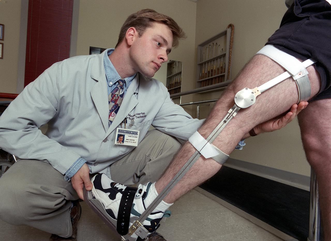
A knee brace that uses Space Shuttle propulsion technology has moved a step closer to being available to help knee injury and stroke patients and may possibly benefit patients with birth defects, spinal cord injuries, and post-polio conditions. After years of hard work, inventors at NASA's Marshall Space Flight Center (MSFC) in Huntsville, Alabama, have turned over the final design and prototype to industry partners at Horton's Orthotic Lab in Little Rock, Arkansas for further clinical testing. The device, called the Selectively Lockable Knee Brace, may mean faster, less painful rehabilitation for patients by allowing the knee to move when weight is not on the heel. Devices currently on the market lock the knee in a rigid, straight-leg position, or allow continuous free motion. Pictured here is a knee brace prototype being tested and fitted at Horton's Orthotic Lab. The knee brace is just one example of how space technology is being used to improve the lives of people on Earth. NASA's MSFC inventors Michael Shadoan and Neill Myers are space propulsion engineers who use the same mechanisms and materials to build systems for rockets that they used to design and develop the knee brace.

San Luis Obispo, CA - Students at California Polytechnic State University prepare to integrate mini research satellites, or CubeSats into a Poly Picosatellite Orbital Deployer, or PPOD, container. The PPOD and CubeSat Project were developed by California Polytechnic State University in San Luis Obispo, Calif., and Stanford University’s Space Systems Development Lab for use on NASA’s Educational Launch of Nanosatellite, or ELaNa missions. Each CubeSat measures about four inches cubed; about the same volume as a quart. The CubeSats weigh about 2.2 pounds, must conform to standard aerospace materials and must operate without propulsion. U.S. Air Force Photo/Mr. Jerry E. Clemens, Jr.
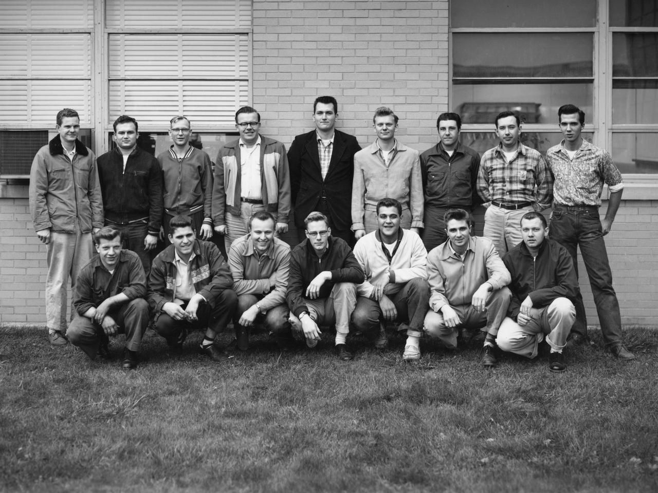
A group of apprentices takes a break from their studies to pose for a photograph at the National Advisory Committee for Aeronautics (NACA) Lewis Flight Propulsion Laboratory. To facilitate the close interaction of the lab’s engineers, mechanics, technicians, and scientists, Lewis Director Ray Sharp established a four-year apprentice program to train craftsmen on a particular trade and basic scientific principles. The apprentice school covered a variety of trades, from aircraft mechanic to electronic instrumentation, machinist, and altitude systems mechanic. The school was established in 1942, but faltered when over 90 percent of its students entered the military. After World War II, 40 of the original members returned to the NACA lab. In some cases they were bumped to journeymen positions because of training received in the military. The honorary first class in 1949 had only 15 graduates, but the number steadily increased to 45 with the next class in 1952 and to 110 in 1957. There were over 600 graduates by 1969, and the program remained strong for decades. Many of the laboratory’s future managers began their careers as apprentices. The program, which was certified by both the Department of Labor and the State of Ohio, included classroom lectures, the study of models, and hands-on work. The apprentices rotated through the various shops and facilities to provide them with a well-rounded understanding of the work at the lab.
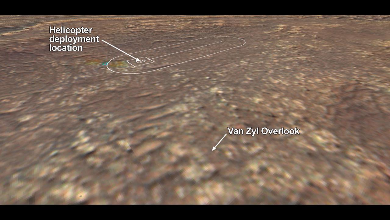
The location where NASA's Mars 2020 Perseverance rover will observe the Ingenuity Mars Helicopter's attempt at powered controlled flight at Mars is called "Van Zyl Overlook," after Jakob van Zyl. Van Zyl was the team's longtime colleague, mentor, and leader at NASA's Jet Propulsion Laboratory in Southern California. He passed away unexpectedly in August 2020, about a month after the launch of Perseverance. Van Zyl joined JPL in 1986 and served in crucial roles at the Lab over a 33-year career, including as director for the Astronomy and Physics Directorate, associate director for project formulation and strategy, and finally director for the Solar System Exploration Directorate. As leader of solar system exploration at JPL, he oversaw successful operations of such NASA missions as Juno, Dawn, and Cassini, the implementation of the Mars InSight lander and MarCO CubeSats, as well as ongoing development of Europa Clipper, Psyche, and all of JPL's instruments and Ingenuity. https://photojournal.jpl.nasa.gov/catalog/PIA24435
An apprentice at the National Advisory Committee for Aeronautics (NACA) Lewis Flight Propulsion Laboratory shown training on the altitude supply air systems in the Engine Research Building. An ongoing four-year apprentice program was established at the laboratory in 1949 to facilitate the close interaction of the lab’s engineers, mechanics, technicians, and scientists. The apprentice school covered a variety of trades including aircraft mechanic, electronics instrumentation, machinist, and altitude systems mechanic, seen in this photograph. The apprentices rotated through the various shops and facilities to provide them with a well-rounded understanding of the work at the lab. The specialized skills required meant that NACA apprentices were held to a higher standard than those in industry. They had to pass written civil service exams before entering the program. Previous experience with mechanical model airplanes, radio transmission, six months of work experience, or one year of trade school was required. The Lewis program was certified by both the Department of Labor and the State of Ohio. One hundred fifty of the 2,000 hours of annual training were spent in the classroom. The remainder was devoted to study of models and hands-on work in the facilities. Examinations were coupled with evaluation by supervisors in the shops. The apprentices were promoted through a series of grades until they reached journeyman status. Those who excelled in the Apprentice Program would be considered for a separate five-year engineering draftsman program.
San Luis Obispo, CA - Roland Coelho and Ryan Nugent, students at California Polytechnic State University, integrate mini research satellites or CubeSats into a Poly Picosatellite Orbital Deployer, or PPOD, container. The PPOD and CubeSat Project were developed by California Polytechnic State University in San Luis Obispo, Calif., and Stanford University’s Space Systems Development Lab for use on NASA’s Educational Launch of Nanosatellite, or ELaNa missions. Each CubeSat measures about four inches cubed; about the same volume as a quart. The CubeSats weigh about 2.2 pounds, must conform to standard aerospace materials and must operate without propulsion. U.S. Air Force Photo/Mr. Jerry E. Clemens, Jr.
San Luis Obispo, CA - Roland Coelho and Ryan Nugent, students at California Polytechnic State University, integrate mini research satellites or CubeSats into a Poly Picosatellite Orbital Deployer, or PPOD, container. The PPOD and CubeSat Project were developed by California Polytechnic State University in San Luis Obispo, Calif., and Stanford University’s Space Systems Development Lab for use on NASA’s Educational Launch of Nanosatellite, or ELaNa missions. Each CubeSat measures about four inches cubed; about the same volume as a quart. The CubeSats weigh about 2.2 pounds, must conform to standard aerospace materials and must operate without propulsion. U.S. Air Force Photo/Mr. Jerry E. Clemens, Jr.
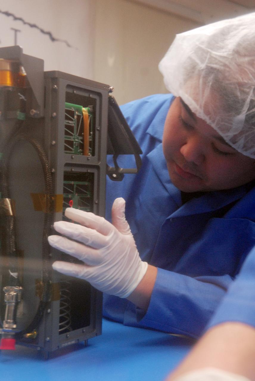
San Luis Obispo, CA - Roland Coelho, a student at California Polytechnic State University, inspects the integration alignment of mini research satellites or CubeSats into a Poly Picosatellite Orbital Deployer, or PPOD, container. The PPOD and CubeSat Project were developed by California Polytechnic State University in San Luis Obispo, Calif., and Stanford University’s Space Systems Development Lab for use on NASA’s Educational Launch of Nanosatellite, or ELaNa missions. Each CubeSat measures about four inches cubed; about the same volume as a quart. The CubeSats weigh about 2.2 pounds, must conform to standard aerospace materials and must operate without propulsion. U.S. Air Force Photo/Mr. Jerry E. Clemens, Jr.
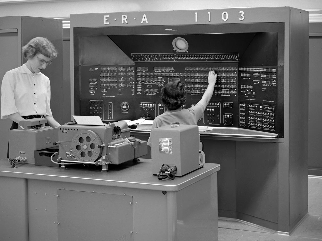
The new 10-by 10-Foot Supersonic Wind Tunnel at the Lewis Flight Propulsion Laboratory included high tech data acquisition and analysis systems. The reliable gathering of pressure, speed, temperature, and other data from test runs in the facilities was critical to the research process. Throughout the 1940s and early 1950s female employees, known as computers, recorded all test data and performed initial calculations by hand. The introduction of punch card computers in the late 1940s gradually reduced the number of hands-on calculations. In the mid-1950s new computational machines were installed in the office building of the 10-by 10-Foot tunnel. The new systems included this UNIVAC 1103 vacuum tube computer—the lab’s first centralized computer system. The programming was done on paper tape and fed into the machine. The 10-by 10 computer center also included the Lewis-designed Computer Automated Digital Encoder (CADDE) and Digital Automated Multiple Pressure Recorder (DAMPR) systems which converted test data to binary-coded decimal numbers and recorded test pressures automatically, respectively. The systems primarily served the 10-by 10, but were also applied to the other large facilities. Engineering Research Associates (ERA) developed the initial UNIVAC computer for the Navy in the late 1940s. In 1952 the company designed a commercial version, the UNIVAC 1103. The 1103 was the first computer designed by Seymour Cray and the first commercially successful computer.
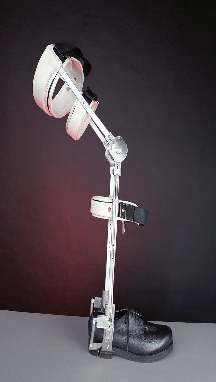
A knee brace that uses Space Shuttle propulsion technology has moved a step closer to being available to help knee injury and stroke patients and may possibly benefit patients with birth defects, spinal cord injuries, and post-polio conditions. After years of hard work, inventors at NASA's Marshall Space Flight Center (MSFC) in Huntsville, Alabama, have turned over the final design and prototype to industry partners at Horton's Orthotic Lab in Little Rock, Arkansas for further clinical testing. The device, called the Selectively Lockable Knee Brace, may mean faster, less painful rehabilitation for patients by allowing the knee to move when weight is not on the heel. Devices currently on the market lock the knee in a rigid, straight-leg position, or allow continuous free motion. The knee brace is just one example of how space technology is being used to improve the lives of people on Earth. NASA's MSFC inventors Michael Shadoan and Neill Myers are space propulsion engineers who use the same mechanisms and materials to build systems for rockets that they used to design and develop the knee brace.
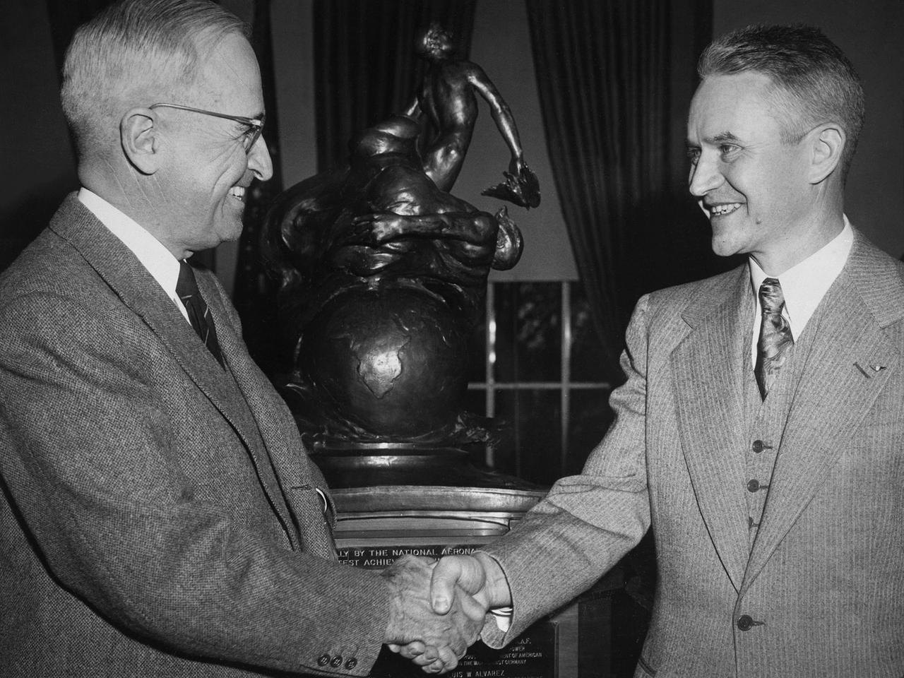
Lewis Rodert, then of the National Advisory Committee for Aeronautics (NACA) Lewis Flight Propulsion Laboratory, receives the Collier Trophy from President Harry Truman for his work in the design and development of an ice prevention system for aircraft. The accumulation of ice on an aircraft had been a critical issue for years. Rodert developed a method of transferring engine heat to the wings and other vulnerable components to prevent ice buildup. Rodert began his icing investigations at Langley Memorial Aeronautical Laboratory in 1936. The NACA ordered a Lockheed 12A aircraft to be built using Rodert’s deicing system. The aircraft successfully flew through icing conditions during the following winter. Soon thereafter the military incorporated the system into a Consolidated B-24D Liberator and several other military aircraft, including a North American XB-25F. Rodert and the NACA icing program transferred to the Lewis lab in Cleveland in 1946. In Cleveland, the focus turned to the study of cloud composition and the causes of icing. Rodert’s role at Lewis diminished over the ensuing years. Rodert was honored in 1947 for his Collier Trophy at ceremonies at Langley, Ames, and then finally Lewis.
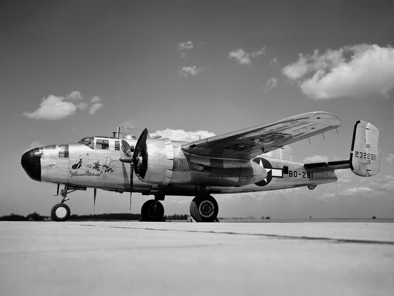
In 1946 the Lewis Flight Propulsion Laboratory became the NACA’s official icing research center. In addition to the Icing Research Tunnel, the lab possessed several aircraft modified for icing work, including a Consolidated B-24M Liberator and a North American XB-25E Mitchell, seen here. The XB-25E’s frequent engine fires allegedly resulted in its “Flamin’ Maimie” nickname. The aircraft’s nose art, visible in this photograph, includes a leather-jacketed mechanic with an extinguisher fleeing a fiery woman. North American developed the B-25 in the mid-1930s as a transport aircraft, but it was hurriedly reconfigured as a medium bomber for World War II. This XB-25E was a single prototype designed in 1942 specifically to test an exhaust gas ice prevention system developed by NACA researcher Lewis Rodert. The system circulated the engines’ hot bleed air to the wings, windshield, and tail. The XB-25E was utilized at the NACA’s Ames Aeronautical Laboratory for two years before being transferred to Cleveland in July 1944. NACA Lewis mechanics modified the aircraft further by installing electrical heating in the front fuselage, propellers, inboard sing, cowls, and antennae. Lewis pilots flew the B-24M and XB-25E into perilous weather conditions all across the country to study both deicing technologies and the physics of ice-producing clouds. These dangerous flights led to advances in weather sensing instruments and flight planning.
Reflectors setup in the La Selva region of the Costa Rican rain forest by scientist Paul Siqueira from NASA’s Jet Propulsion Lab. These reflectors are used by JPL scientists onboard Dryden's DC-8 aircraft to calibrate the Airborne Synthetic Aperture Radar (AirSAR) system. Scientists place these reflectors at known points on the ground, allowing researchers onboard the aircraft to verify their data. AirSAR 2004 Mesoamerica is a three-week expedition by an international team of scientists that uses an all-weather imaging tool, called the Airborne Synthetic Aperture Radar (AirSAR) which is located onboard NASA's DC-8 airborne laboratory. Scientists from many parts of the world including NASA's Jet Propulsion Laboratory are combining ground research done in several areas in Central America with NASA's AirSAR technology to improve and expand on the quality of research they are able to conduct. The radar, developed by NASA's Jet Propulsion Laboratory, can penetrate clouds and also collect data at night. Its high-resolution sensors operate at multiple wavelengths and modes, allowing AirSAR to see beneath treetops, through thin sand, and dry snow pack. AirSAR's 2004 campaign is a collaboration of many U.S. and Central American institutions and scientists, including NASA; the National Science Foundation; the Smithsonian Institution; National Geographic; Conservation International; the Organization of Tropical Studies; the Central American Commission for Environment and Development; and the Inter-American Development Bank.
Reflectors setup in the La Selva region of the Costa Rican rain forest by scientist Paul Siqueira from NASA’s Jet Propulsion Lab. These reflectors are used by JPL scientists onboard Dryden's DC-8 aircraft to calibrate the Airborne Synthetic Aperture Radar (AirSAR) system. Scientists place these reflectors at known points on the ground, allowing researchers onboard the aircraft to verify their data. AirSAR 2004 Mesoamerica is a three-week expedition by an international team of scientists that uses an all-weather imaging tool, called the Airborne Synthetic Aperture Radar (AirSAR) which is located onboard NASA's DC-8 airborne laboratory. Scientists from many parts of the world including NASA's Jet Propulsion Laboratory are combining ground research done in several areas in Central America with NASA's AirSAR technology to improve and expand on the quality of research they are able to conduct. The radar, developed by NASA's Jet Propulsion Laboratory, can penetrate clouds and also collect data at night. Its high-resolution sensors operate at multiple wavelengths and modes, allowing AirSAR to see beneath treetops, through thin sand, and dry snow pack. AirSAR's 2004 campaign is a collaboration of many U.S. and Central American institutions and scientists, including NASA; the National Science Foundation; the Smithsonian Institution; National Geographic; Conservation International; the Organization of Tropical Studies; the Central American Commission for Environment and Development; and the Inter-American Development Bank.
San Luis Obispo, Calif. -- 101116-F-8290C-045 -- Students at California Polytechnic State University Cal Poly prepare to integrate miniature research satellites called CubeSats into a Poly Picosatellite Orbital Deployer PPOD container. The PPOD and CubeSat Project were developed by Cal Poly and Stanford University’s Space Systems Development Lab for use on NASA’s Educational Launch of Nanosatellite ELaNa missions. Each CubeSat measures about 4-inches cubed and is about the same volume as a quart. The CubeSats weigh about 2.2 pounds, must conform to standard aerospace materials and must operate without propulsion. The satellites are being prepared to launch with NASA's Glory spacecraft aboard an Orbital Sciences Corp. Taurus XL rocket, targeted to lift off Feb. 23, 2011, from Vandenberg's Space Launch Complex 576-E. Glory is scheduled to collect data on the properties of aerosols and black carbon from its place in low Earth orbit. It also will help scientists understand how the sun's irradiance affects Earth's climate. Photo credit: U.S. Air Force/Jerry E. Clemens Jr.
San Luis Obispo, Calif. -- 101116-F-8290C-059 -- Roland Coelho and Ryan Nugent, students at California Polytechnic State University Cal Poly, integrate miniature research satellites called CubeSats into a Poly Picosatellite Orbital Deployer PPOD container. The PPOD and CubeSat Project were developed by Cal Poly and Stanford University’s Space Systems Development Lab for use on NASA’s Educational Launch of Nanosatellite ELaNa missions. Each CubeSat measures about 4-inches cubed and is about the same volume as a quart. The CubeSats weigh about 2.2 pounds, must conform to standard aerospace materials and must operate without propulsion. The satellites are being prepared to launch with NASA's Glory spacecraft aboard an Orbital Sciences Corp. Taurus XL rocket, targeted to lift off Feb. 23, 2011, from Vandenberg's Space Launch Complex 576-E. Glory is scheduled to collect data on the properties of aerosols and black carbon from its place in low Earth orbit. It also will help scientists understand how the sun's irradiance affects Earth's climate. Photo credit: U.S. Air Force/Jerry E. Clemens Jr.

San Luis Obispo, Calif. -- 101116-F-8290C-054 -- Roland Coelho and Ryan Nugent, students at California Polytechnic State University Cal Poly, integrate miniature research satellites called CubeSats into a Poly Picosatellite Orbital Deployer PPOD container. The PPOD and CubeSat Project were developed by Cal Poly and Stanford University’s Space Systems Development Lab for use on NASA’s Educational Launch of Nanosatellite ELaNa missions. Each CubeSat measures about 4-inches cubed and is about the same volume as a quart. The CubeSats weigh about 2.2 pounds, must conform to standard aerospace materials and must operate without propulsion. The satellites are being prepared to launch with NASA's Glory spacecraft aboard an Orbital Sciences Corp. Taurus XL rocket, targeted to lift off Feb. 23, 2011, from Vandenberg's Space Launch Complex 576-E. Glory is scheduled to collect data on the properties of aerosols and black carbon from its place in low Earth orbit. It also will help scientists understand how the sun's irradiance affects Earth's climate. Photo credit: U.S. Air Force/Jerry E. Clemens Jr.

San Luis Obispo, Calif. -- 101116-F-8290C-060 -- Roland Coelho, a student at California Polytechnic State University Cal Poly, inspects the integration alignment of miniature research satellites called a CubeSats into a Poly Picosatellite Orbital Deployer PPOD container. The PPOD and CubeSat Project were developed by Cal Poly and Stanford University’s Space Systems Development Lab for use on NASA’s Educational Launch of Nanosatellite ELaNa missions. Each CubeSat measures about 4-inches cubed and is about the same volume as a quart. The CubeSats weigh about 2.2 pounds, must conform to standard aerospace materials and must operate without propulsion. The satellites are being prepared to launch with NASA's Glory spacecraft aboard an Orbital Sciences Corp. Taurus XL rocket, targeted to lift off Feb. 23, 2011, from Vandenberg's Space Launch Complex 576-E. Glory is scheduled to collect data on the properties of aerosols and black carbon from its place in low Earth orbit. It also will help scientists understand how the sun's irradiance affects Earth's climate. Photo credit: U.S. Air Force/Jerry E. Clemens Jr.

Engineers at NASA's Jet Propulsion Laboratory in Southern California examine one of Psyche's solar arrays during a deployment test in the Lab's High Bay 2 clean room in late February 2022. The twin arrays are together about 800 square feet (75 square meters) – the largest ever deployed at JPL. Part of a solar electric propulsion system provided by Maxar Technologies, they will power the spacecraft on its 1.5 billion-mile (2.4 billion-kilometer) journey to the large, metal-rich asteroid Psyche. Only the three center panels on each five-panel, cross-shaped array can be deployed at JPL due to the limitations of the gravity-offload fixture and the opposing direction of rotation of the cross panels. Deployment of the two cross panels was previously performed at Maxar with different equipment. After further spacecraft testing is completed at JPL, the arrays will be removed and returned to Maxar in order to repeat the cross-panel deployments, make any final repairs to the solar cells, and test overall performance. The arrays then get shipped from Maxar to NASA's Kennedy Space Center in Florida, where they will be reintegrated onto the spacecraft in preparation for launch in August 2022. About an hour after launch, Psyche will deploy the arrays sequentially, first unfolding the three lengthwise center panels, then the two cross panels on one wing before repeating the process with the other wing. Each array takes about 7 ½ minutes to unfurl and latch into place. Each array is 37.1 feet (11.3 meters) long and 24 feet (7.3 meters) wide when fully deployed. With arrays deployed on either side of the chassis, the spacecraft is about the size of a singles tennis court: 81 feet long (24.7 meters) and 24 feet (7.3 meters) wide. https://photojournal.jpl.nasa.gov/catalog/PIA25134
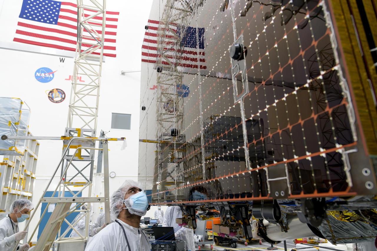
An engineer at NASA's Jet Propulsion Laboratory in Southern California examines a panel on Psyche's stowed solar arrays prior to a deployment test in the Lab's High Bay 2 clean room in February 2022. The twin arrays are together about 800 square feet (75 square meters) – the largest ever deployed at JPL. Part of a solar electric propulsion system provided by Maxar Technologies, they will power the spacecraft on its 1.5 billion-mile (2.4 billion-kilometer) journey to the large, metal-rich asteroid Psyche. Only the three center panels on each five-panel, cross-shaped array can be deployed at JPL due to the limitations of the gravity-offload fixture and the opposing direction of rotation of the cross panels. Deployment of the two cross panels was previously performed at Maxar with different equipment. After further spacecraft testing is completed at JPL, the arrays will be removed and returned to Maxar in order to repeat the cross-panel deployments, make any final repairs to the solar cells, and test overall performance. The arrays then get shipped from Maxar to NASA's Kennedy Space Center in Florida, where they will be reintegrated onto the spacecraft in preparation for launch in August 2022. About an hour after launch, Psyche will deploy the arrays sequentially, first unfolding the three lengthwise center panels, then the two cross panels on one wing before repeating the process with the other wing. Each array takes about 7 ½ minutes to unfurl and latch into place. Each array is 37.1 feet (11.3 meters) long and 24 feet (7.3 meters) wide when fully deployed. With arrays deployed on either side of the chassis, the spacecraft is about the size of a singles tennis court: 81 feet long (24.7 meters) and 24 feet (7.3 meters) wide. https://photojournal.jpl.nasa.gov/catalog/PIA25133
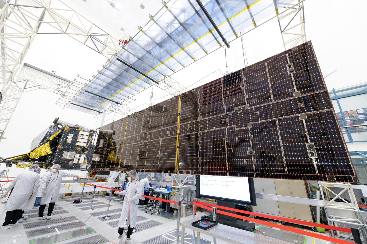
Engineers at NASA's Jet Propulsion Laboratory in Southern California successfully deployed a solar array installed on the agency's Psyche spacecraft. It was one of two deployed during testing in the Lab's High Bay 2 clean room in late February 2022. The twin arrays are together about 800 square feet (75 square meters) – the largest ever deployed at JPL. Part of a solar electric propulsion system provided by Maxar Technologies, they will power the spacecraft on its 1.5 billion-mile (2.4 billion-kilometer) journey to the large, metal-rich asteroid Psyche. Only the three center panels on each five-panel, cross-shaped array can be deployed at JPL due to the limitations of the gravity-offload fixture and the opposing direction of rotation of the cross panels. Deployment of the two cross panels was previously performed at Maxar with different equipment. After further spacecraft testing is completed at JPL, the arrays will be removed and returned to Maxar in order to repeat the cross-panel deployments, make any final repairs to the solar cells, and test overall performance. The arrays then get shipped from Maxar to NASA's Kennedy Space Center in Florida, where they will be reintegrated onto the spacecraft in preparation for launch in August 2022. About an hour after launch, Psyche will deploy the arrays sequentially, first unfolding the three lengthwise center panels, then the two cross panels on one wing before repeating the process with the other wing. Each array takes about 7 ½ minutes to unfurl and latch into place. Each array is 37.1 feet (11.3 meters) long and 24 feet (7.3 meters) wide when fully deployed. With arrays deployed on either side of the chassis, the spacecraft is about the size of a singles tennis court: 81 feet long (24.7 meters) and 24 feet (7.3 meters) wide. https://photojournal.jpl.nasa.gov/catalog/PIA25135
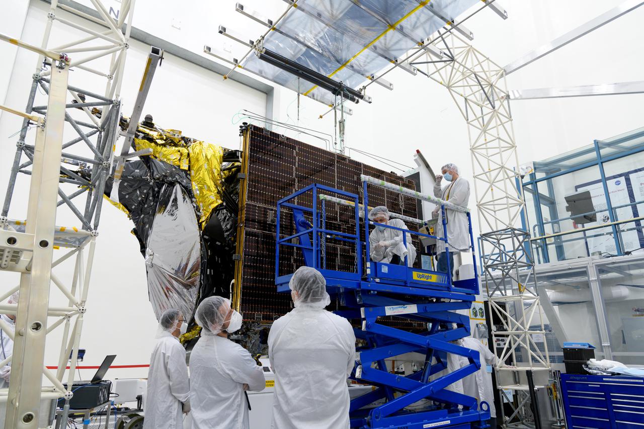
Engineers at NASA's Jet Propulsion Laboratory in Southern California examine one of Psyche's stowed solar arrays prior to a deployment test in the Lab's High Bay 2 clean room in late February 2022. The twin arrays are together about 800 square feet (75 square meters) – the largest ever deployed at JPL. Part of a solar electric propulsion system provided by Maxar Technologies, they will power the spacecraft on its 1.5 billion-mile (2.4 billion-kilometer) journey to the large, metal-rich asteroid Psyche. Only the three center panels on each five-panel, cross-shaped array can be deployed at JPL due to the limitations of the gravity-offload fixture and the opposing direction of rotation of the cross panels. Deployment of the two cross panels was previously performed at Maxar with different equipment. After further spacecraft testing is completed at JPL, the arrays will be removed and returned to Maxar in order to repeat the cross-panel deployments, make any final repairs to the solar cells, and test overall performance. The arrays then get shipped from Maxar to NASA's Kennedy Space Center in Florida, where they will be reintegrated onto the spacecraft in preparation for launch in August 2022. About an hour after launch, Psyche will deploy the arrays sequentially, first unfolding the three lengthwise center panels, then the two cross panels on one wing before repeating the process with the other wing. Each array takes about 7 ½ minutes to unfurl and latch into place. Each array is 37.1 feet (11.3 meters) long and 24 feet (7.3 meters) wide when fully deployed. With arrays deployed on either side of the chassis, the spacecraft is about the size of a singles tennis court: 81 feet long (24.7 meters) and 24 feet (7.3 meters) wide. https://photojournal.jpl.nasa.gov/catalog/PIA25132
On Oct. 29, 2021, a heavy-duty vehicle transports the Perseverance rover's engineering model from a test lab to the Mars Yard garage at NASA's Jet Propulsion Laboratory. Short for Operational Perseverance Twin for Integration of Mechanisms and Instruments Sent to Mars, OPTIMISM is generically referred to as a vehicle system test bed. As with vehicle system test beds for other Mars rovers, OPTIMISM is used to test moves and scenarios in the Mars Yard's simulated Red Planet landscape to help ensure that its twin on Mars can safely execute the commands sent by Earth-bound controllers. The tests could also potentially reveal unexpected problems Perseverance might encounter. With longer drives in Perseverance's near future, another job for OPTIMISM will involve presenting new challenges to the rover's autonomous navigation system, or AutoNav. A key objective for Perseverance's mission on Mars is astrobiology, including the search for signs of ancient microbial life. The rover will characterize the planet's geology and past climate, pave the way for human exploration of the Red Planet, and be the first mission to collect and cache Martian rock and regolith (broken rock and dust). Subsequent NASA missions, in cooperation with ESA (European Space Agency), would send spacecraft to Mars to collect these sealed samples from the surface and return them to Earth for in-depth analysis. The Mars 2020 Perseverance mission is part of NASA's Moon to Mars exploration approach, which includes Artemis missions to the Moon that will help prepare for human exploration of the Red Planet. https://photojournal.jpl.nasa.gov/catalog/PIA24526
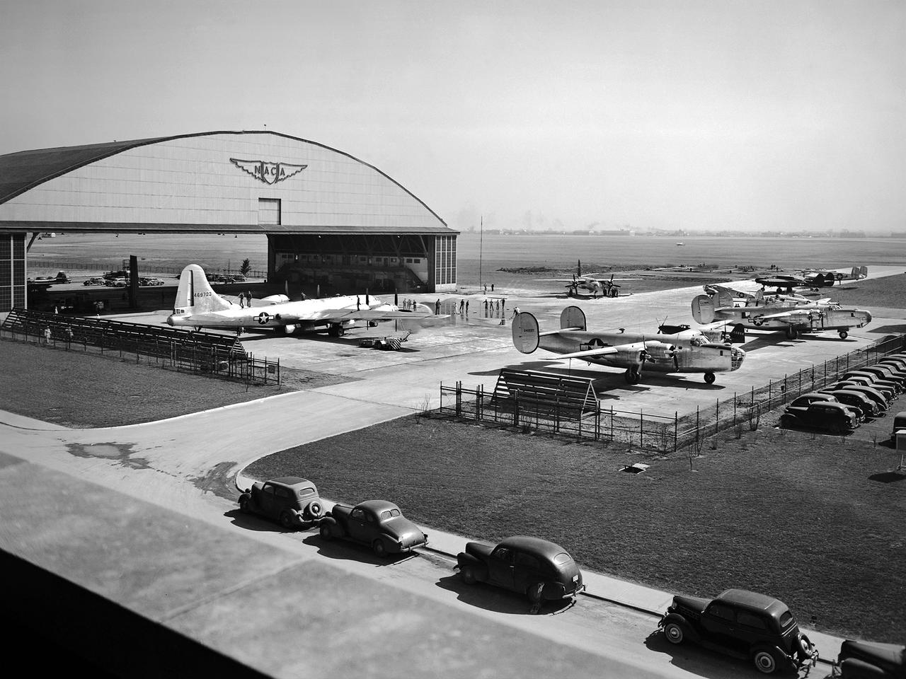
This fleet of military aircraft was used in the 1940s for research at the National Advisory Committee for Aeronautics (NACA) Lewis Flight Propulsion Laboratory in Cleveland, Ohio. The NACA Lewis flight research program was established in March 1943 to augment the lab’s wartime research efforts. NACA Lewis possessed a host of wind tunnels, test stands, and other ground facilities designed to replicate flight conditions, but actual flight tests remained an integral research tool. The military loaned NACA Lewis 15 different aircraft during World War II and six others in the six months following the end of hostilities. During the war these aircraft supported three main efforts: the improved performance of reciprocating engines, better fuel additives and mixtures, and deicing systems. The wartime researchers used the types of aircraft which the studies were intended to improve. After the war the research aircraft served as test beds to investigate engines or systems that often had little to do with the research aircraft. During the war, NACA Lewis’ three pilots were supported by 16 flight engineers, 36 mechanics, and 10 instrumentation specialists. The visible aircraft, from left to right, are a Boeing B-29 Superfortress, a Martin B-26A Marauder, two Consolidated B-24 Liberators, a Cessna UC-78 Bobcat, and a Northrop P-61 Black Widow. Partially obscured are a North American P-51 Mustang, a Bell P-63 King Cobra, a North American AT-6 Texan, and a Lockheed RA-29 Hudson.