Propulsion Systems Laboratory, PSL Fundamental Aero Test
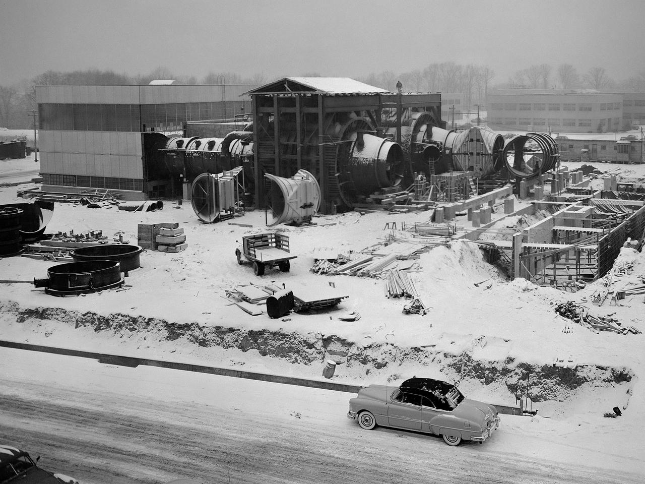
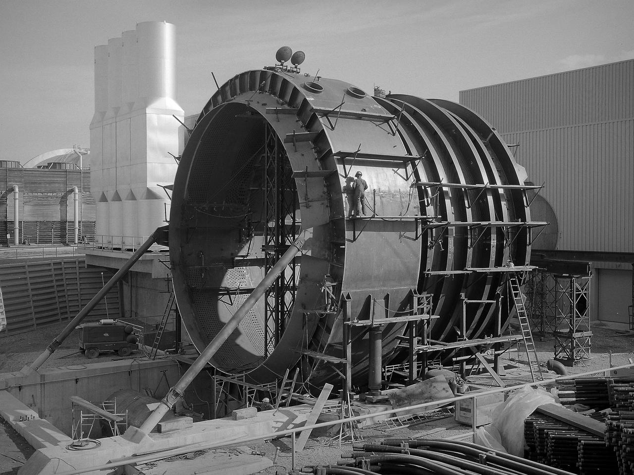
Construction of the Propulsion Systems Laboratory No. 1 and 2 at the National Advisory Committee for Aeronautics (NACA) Lewis Flight Propulsion Laboratory. When it began operation in late 1952, the Propulsion Systems Laboratory was the NACA’s most powerful facility for testing full-scale engines at simulated flight altitudes. The facility contained two altitude simulating test chambers which were a technological combination of the static sea-level test stands and the complex Altitude Wind Tunnel, which recreated actual flight conditions on a larger scale. NACA Lewis began designing the new facility in 1947 as part of a comprehensive plan to improve the altitude testing capabilities across the lab. The exhaust, refrigeration, and combustion air systems from all the major test facilities were linked. In this way, different facilities could be used to complement the capabilities of one another. Propulsion Systems Laboratory construction began in late summer 1949 with the installation of an overhead exhaust pipe connecting the facility to the Altitude Wind Tunnel and Engine Research Building. The large test section pieces arriving in early 1951, when this photograph was taken. The two primary coolers for the altitude exhaust are in place within the framework near the center of the photograph.
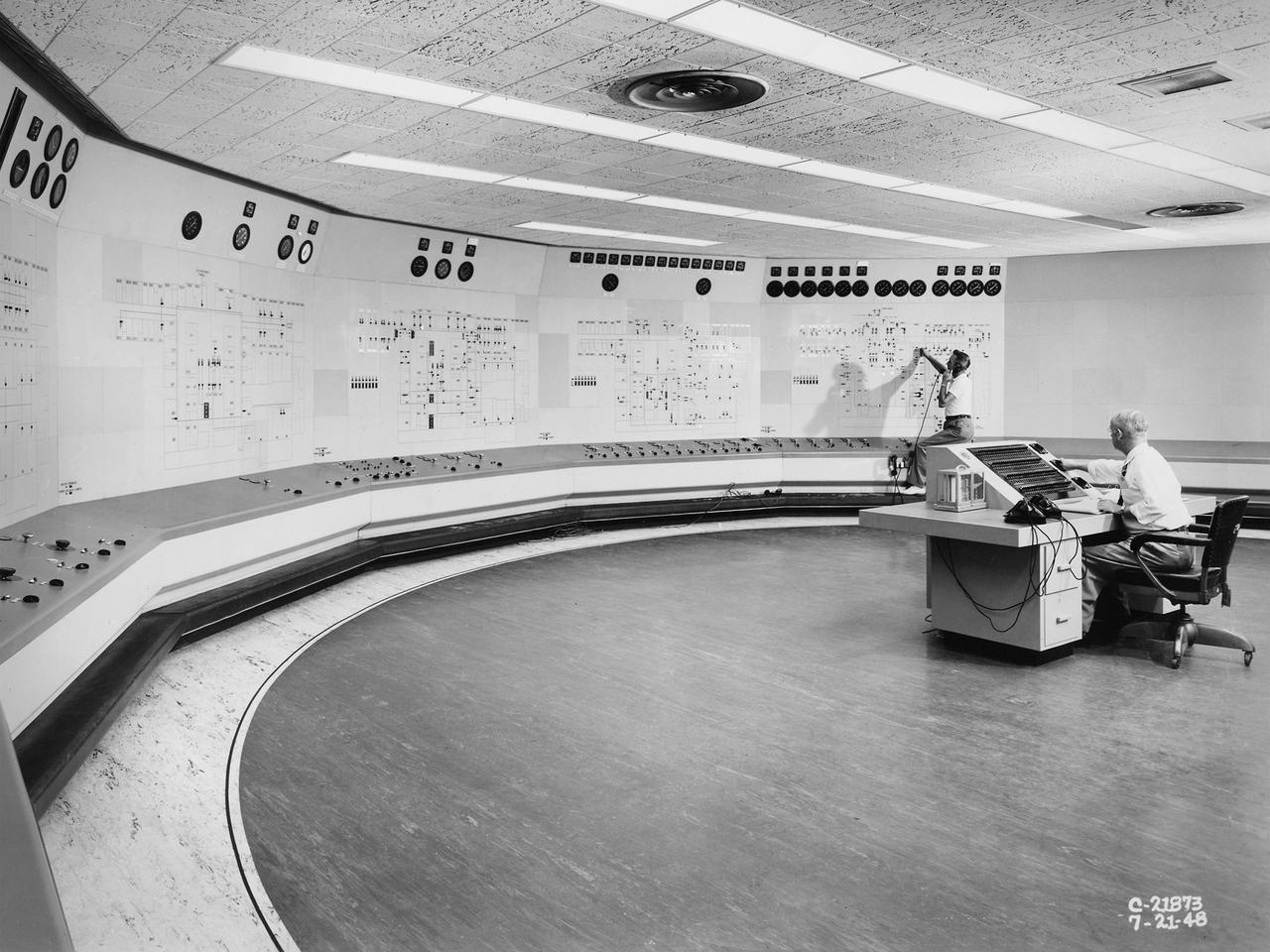
Operators in the Engine Research Building’s Central Control Room at the National Advisory Committee for Aeronautics (NACA) Lewis Flight Propulsion Laboratory. The massive 4.25-acre Engine Research Building contains dozens of test cells, test stands, and altitude chambers. A powerful collection of compressors and exhausters located in the central portion of the basement provided process air and exhaust for these test areas. This system is connected to similar process air systems in the laboratory’s other large test facilities. The Central Control Room coordinates this activity and communicates with the local utilities. This photograph was taken just after a major upgrade to the control room in 1948. The panels on the wall contain rudimentary floor plans of the different Engine Research Building sections with indicator lights and instrumentation for each test cell. The process air equipment included 12 exhausters, four compressors, a refrigeration system, cooling water, and an exhaust system. The operators in the control room kept in contact with engineers running the process air system and those conducting the tests in the test cells. The operators also coordinated with the local power companies to make sure enough electricity was available to operate the powerful compressors and exhausters.
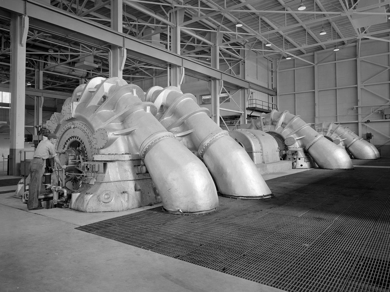
The Propulsion Systems Laboratory’s exhaust system was expanded in 1955 at the National Advisory Committee for Aeronautics (NACA) Lewis Flight Propulsion Laboratory. The facility contained two altitude chambers that were first used to study the increasingly-powerful jet engines of the early 1950s and the ramjets for missile programs such as Navaho and Bomarc. Later, the facility tested large rocket engines and a variety of turbofan engines. The exhaust system served two roles: reducing the density of the air in the test chambers to simulate high altitudes and removing the hot gases exhausted by the engines being tested. These tasks were accomplished by large Roots-Connersville exhauster equipment in the Equipment Building. The original configuration could exhaust the 3500° F gases at a rate of 100 pounds per second when the simulated altitude was 50,000 feet. In 1955, three years after operation started, a fourth line of exhausters was added. There were three centrifugal exhausters capable of supplying 166 pounds of air per second at the test chamber altitude of 50,000 feet or 384 pounds per second at 32,000 feet. These exhausters had two first-stage castings driven by a 10,000-horsepower motor; one second; one third; and one fourth-stage casting driven by a 16,500-horsepower motor. The total inlet volume of the exhausters is 1,650,000 cubic feet of gas per minute. The exhausters were continually improved and upgraded over the years.
The 50-foot diameter primary cooler for the new Propulsion Systems Laboratory No. 3 and 4 facility constructed at the National Aeronautics and Space Administration (NASA) Lewis Research Center. In 1968, 20 years after planning began for the original Propulsion Systems Laboratory test chambers, No. 1 and 2, NASA Lewis began preparations to add two additional and more powerful chambers. The move coincided with the center’s renewed focus on aeronautics in 1966. The new 40-foot long and 24-foot diameter chambers were capable of testing engines twice as powerful any then in existence and significantly larger than those in the original two test chambers. After exiting the engine nozzle, the hot exhaust air passed through a 17-foot diameter water exhaust duct and the 50-foot diameter primary cooler. Twenty-seven hundred water-filled tubes inside the cooler reduced the temperature of the air flow as it passed between the tubes from 3000 to 600 °F. A spray cooler further reduced the temperature of the gases to 150 °F before they were sent to the Central Air Building. Excavations for the new facility were completed by October 1967, and the shell of the building was completed a year later. In September 1968, work began on the new test chambers and associated infrastructure. Construction was completed in late 1972, and the first test was scheduled for February 1973.
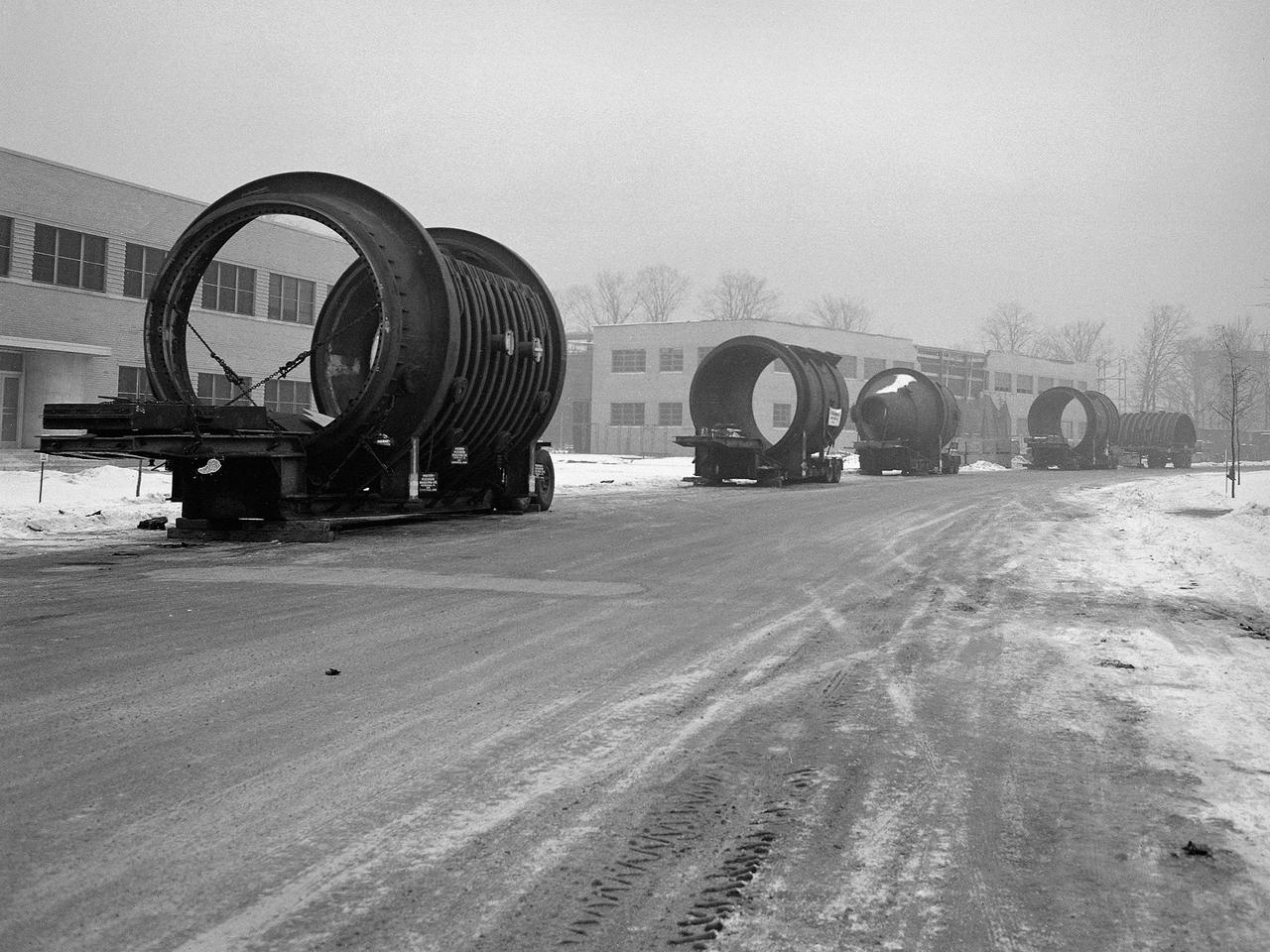
A caravan of large steel castings arrived at the National Advisory Committee for Aeronautics (NACA) Lewis Flight Propulsion Laboratory in January 1951. These pieces would serve as the two 14-foot diameter test chambers in the new Propulsion Systems Laboratory (PSL). NACA Lewis specialized in aircraft engines and offered many engine test facilities. In the late 1940s, however, the NACA realized a larger facility was required to test the newest jet engines. When completed in October 1952, PSL became the nation’s most powerful facility for testing full-scale engines at simulated flight altitudes. NACA engineers began designing the PSL in 1947, and excavations commenced in September 1949. In the spring of 1950, the facility’s supports were erected, and the two large exhaust gas coolers were installed. Work on the Access Building began in early 1951 with the arrival of the large test section pieces, seen in this photograph. The massive pieces were delivered to the area from the Henry Pratt Company by rail and then loaded on a series of flatbed trucks that transported them to Lewis. The nearest vehicle has one of the clamshell access hatches. PSL was initially used to study the jet engines of the early 1950s and ramjets for missile programs such as Navaho and Bomarc. With the advent of the space program in the late 1950s, the facility was used to investigate complex rocket engines, including the Pratt and Whitney RL-10.
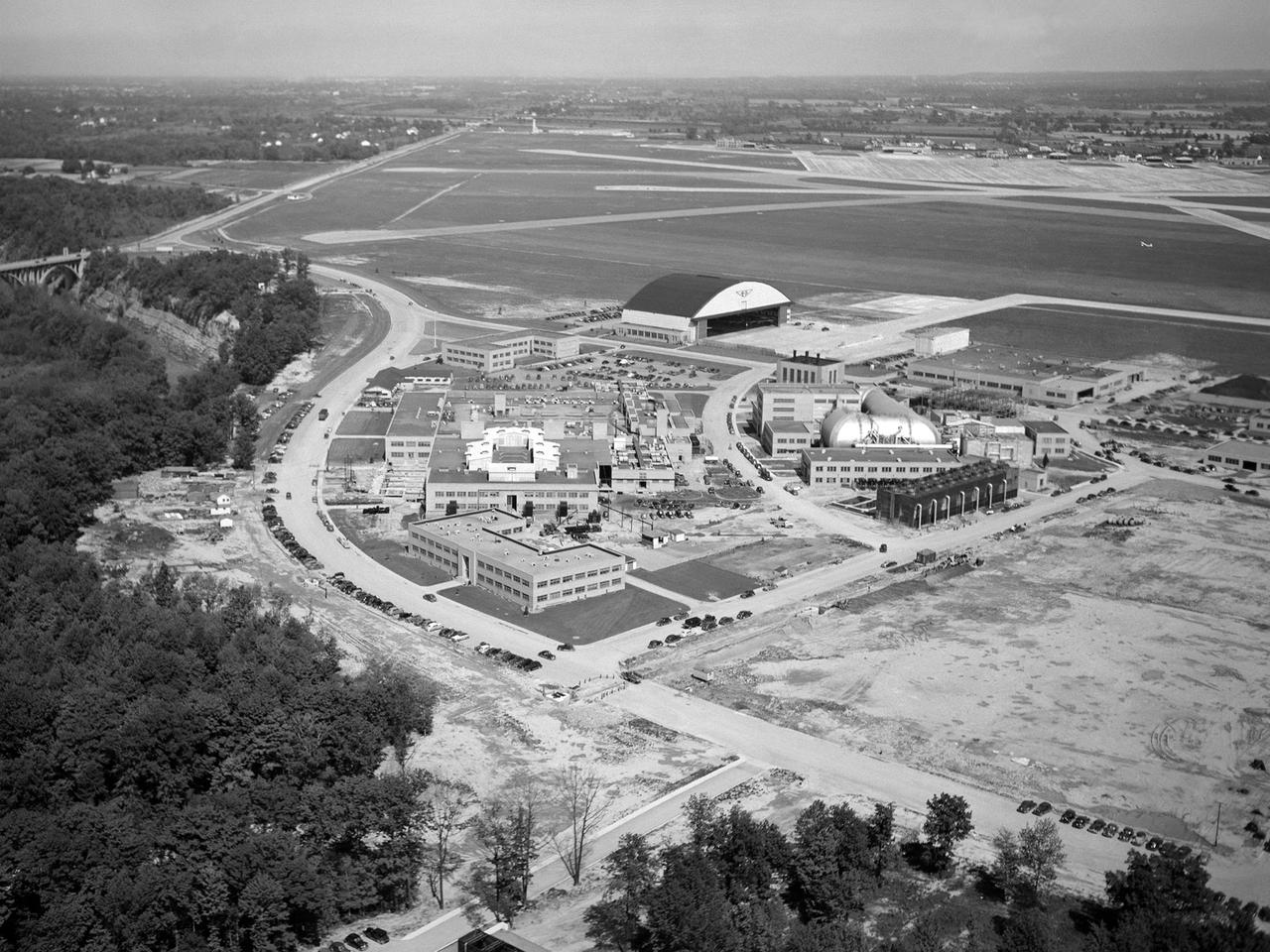
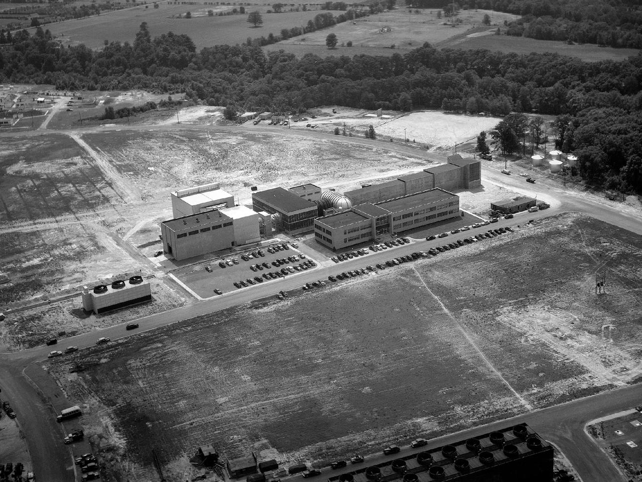
The National Advisory Committee for Aeronautics (NACA) Lewis Flight Propulsion Laboratory in Cleveland, Ohio as seen from the west in May 1946. The Cleveland Municipal Airport is located directly behind. The laboratory was built in the early 1940s to resolve problems associated with aircraft engines. The initial campus contained seven principal buildings: the Engine Research Building, hangar, Fuels and Lubricants Building, Administration Building, Engine Propeller Research Building, Altitude Wind Tunnel, and Icing Research Tunnel. These facilities and their associated support structures were located within an area occupying approximately one-third of the NACA’s property. After World War II ended, the NACA began adding new facilities to address different problems associated with the newer, more powerful engines and high speed flight. Between 1946 and 1955, four new world-class test facilities were built: the 8- by 6-Foot Supersonic Wind Tunnel, the Propulsion Systems Laboratory, the Rocket Engine Test Facility, and the 10- by 10-Foot Supersonic Wind Tunnel. These large facilities occupied the remainder of the NACA’s semicircular property. The Lewis laboratory expanded again in the late 1950s and early 1960s as the space program commenced. Lewis purchased additional land in areas adjacent to the original laboratory and acquired a large 9000-acre site located 60 miles to the west in Sandusky, Ohio. The new site became known as Plum Brook Station.
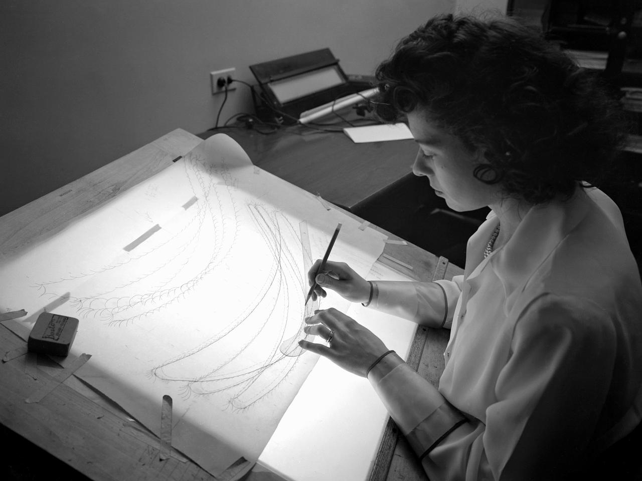
A female computer plotting compressor data in the Engine Research Building at the NACA’s Lewis Flight Propulsion Laboratory. The Computing Section was introduced during World War II to relieve short-handed research engineers of some of the tedious data-taking work. The computers made the initial computations and plotted the data graphically. The researcher then analyzed the data and either summarized the findings in a report or made modifications or ran the test again. With the introduction of mechanical computer systems in the 1950s the female computers learned how to encode the punch cards. As the data processing capabilities increased, fewer female computers were needed. Many left on their own to start families, while others earned mathematical degrees and moved into advanced positions.
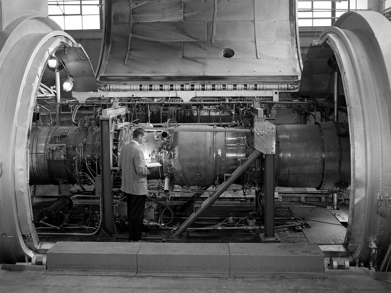
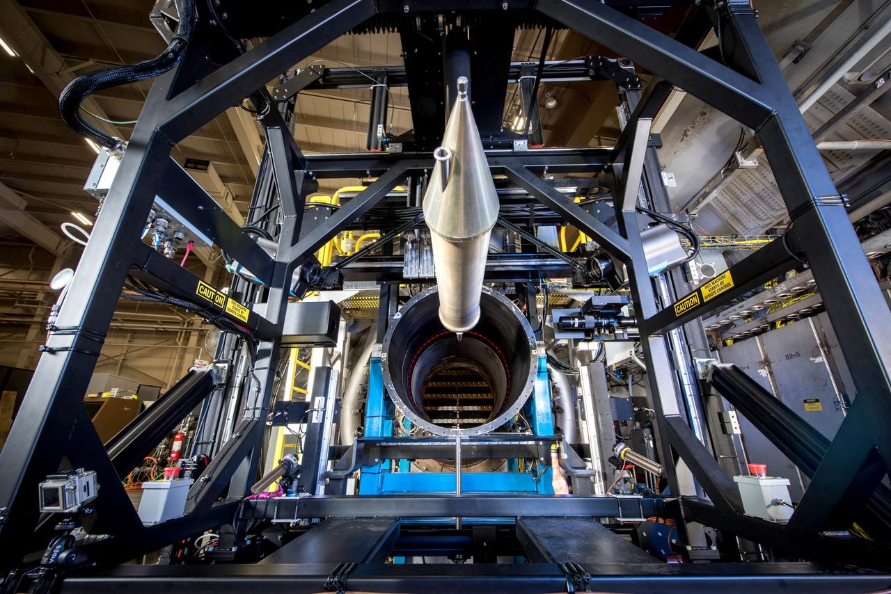
A researcher examines the Orenda Iroquois PS.13 turbojet in a Propulsion Systems Laboratory test chamber at the National Advisory Committee for Aeronautics (NACA) Lewis Flight Propulsion Laboratory. The Iroquois was being developed to power the CF-105 Arrow fighter designed by the Avro Canada Company. Avro began design work on the Arrow jet fighter in 1952. The company’s Orenda branch suggested building a titanium-based PS.13 Iroquois engine after development problems arose with the British engines that Avro had originally intended to use. The 10-stage, 20,000-pound-thrust Iroquois would prove to be more powerful than any contemporary US or British turbojet. It was also significantly lighter and more fuel efficient. An Iroquois was sent to Cleveland in April 1957 so that Lewis researchers could study the engine’s basic performance for the air force in the Propulsion Systems Laboratory. The tests were run over a wide range of speeds and altitudes with variations in exhaust-nozzle area. Initial studies determined the Iroquois’s windmilling and ignition characteristics at high altitude. After operating for 64 minutes, the engine was reignited at altitudes up to the 63,000-foot limit of the facility. Various modifications were attempted to reduce the occurrence of stall but did not totally eradicate the problem. The Arrow jet fighter made its initial flight in March 1958 powered by a substitute engine. In February 1959, however, both the engine and the aircraft programs were cancelled. The world’s superpowers had quickly transitioned from bombers to ballistic missiles which rendered the Avro Arrow prematurely obsolete.
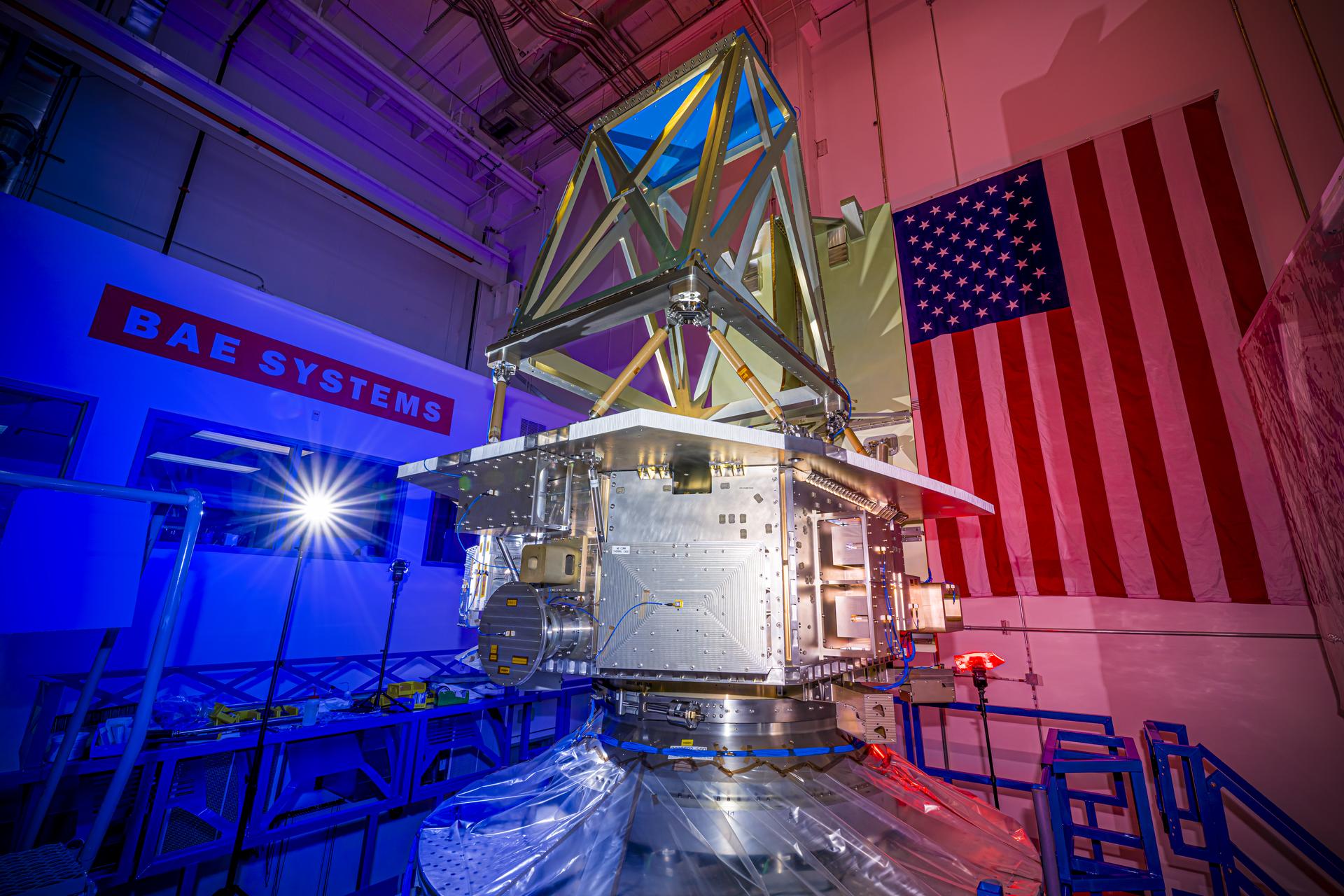
The bus structure for NASA’s Near-Earth Object (NEO) Surveyor is installed on a “shaker table” at BAE Systems Space & Mission Systems in Boulder, Colorado, during vibration testing conducted in August 2025. Mass simulators that mimic the weight and size of the spacecraft’s telescope and sunshade are also attached to the bus for the test. These mass simulators help engineers simulate the conditions flight components will experience during launch so their durability can be verified. Targeting launch in late 2027, the NEO Surveyor mission is led by Professor Amy Mainzer at the University of California, Los Angeles for NASA’s Planetary Defense Coordination Office and is being managed by the agency’s Jet Propulsion Laboratory in Southern California for the Planetary Missions Program Office at NASA’s Marshall Space Flight Center in Huntsville, Alabama. BAE Systems Space & Mission Systems and the Space Dynamics Laboratory in Logan, Utah, and Teledyne are among the companies that were contracted to build the spacecraft and its instrumentation. The Laboratory for Atmospheric and Space Physics at the University of Colorado Boulder will support operations, and IPAC at Caltech in Pasadena, California, is responsible for producing some of the mission’s data products. Caltech manages JPL for NASA. More information about NEO Surveyor is available at: https://science.nasa.gov/mission/neo-surveyor/
Aerial view of the 8- by 6-Foot Supersonic Wind Tunnel in its original configuration at the National Advisory Committee for Aeronautics (NACA) Lewis Flight Propulsion Laboratory. The 8- by 6 was the laboratory’s first large supersonic wind tunnel. It was also the NACA’s most powerful supersonic tunnel, and its first facility capable of running an engine at supersonic speeds. The 8- by 6-foot tunnel has been used to study inlets and exit nozzles, fuel injectors, flameholders, exit nozzles, and controls on ramjet and turbojet propulsion systems. The 8- by 6 was originally an open-throat and non-return tunnel. This meant that the supersonic air flow was blown through the test section and out the other end into the atmosphere. In this photograph, the three drive motors in the structure at the left supplied power to the seven-stage axial-flow compressor in the light-colored structure. The air flow passed through flexible walls which were bent to create the desired speed. The test article was located in the 8- by 6-foot stainless steel test section located inside the steel pressure chamber at the center of this photograph. The tunnel dimensions were then gradually increased to slow the air flow before it exited into the atmosphere. The large two-story building in front of the tunnel was used as office space for the researchers.
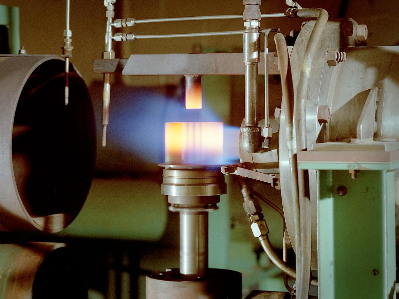
A burner rig heats up a material sample in the Materials and Stresses Building at the National Aeronautics and Space Administration (NASA) Lewis Research Center. Materials technology is an important element in the successful development of advanced airbreathing and rocket propulsion systems. Different types of engines operate in different environments so an array of dependable materials is needed. NASA Lewis began investigating the characteristics of different materials shortly after World War II. In 1949 the materials group was expanded into its own division. The Lewis researchers sought to study and test materials in environments that simulate the environment in which they would operate. The Materials and Stresses Building, built in 1949, contained a number of laboratories to analyze the materials. They are subjected to high temperatures, high stresses, corrosion, irradiation, and hot gasses. The Physics of Solids Laboratory included a cyclotron, cloud chamber, helium cryostat, and metallurgy cave. The Metallographic Laboratory possessed six x-ray diffraction machines, two metalloscopes, and other equipment. The Furnace Room had two large induction machines, a 4500⁰ F graphite furnace, and heat treating equipment. The Powder Laboratory included 60-ton and 3000-ton presses. The Stresses Laboratory included stress rupture machines, fatigue machines, and tensile strength machines.
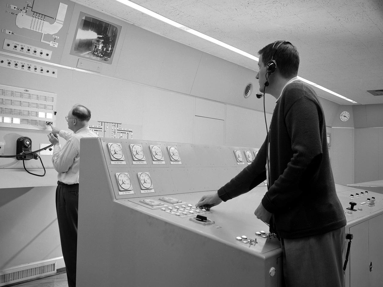
Test engineers monitor an engine firing from the control room of the Rocket Engine Test Facility at the National Advisory Committee for Aeronautics (NACA) Lewis Flight Propulsion Laboratory. The Rocket Engine Test Facility, built in the early 1950s, had a rocket stand designed to evaluate high-energy propellants and rocket engine designs. The facility was used to study numerous different types of rocket engines including the Pratt and Whitney RL-10 engine for the Centaur rocket and Rocketdyne’s F-1 and J-2 engines for the Saturn rockets. The Rocket Engine Test Facility was built in a ravine at the far end of the laboratory because of its use of the dangerous propellants such as liquid hydrogen and liquid fluorine. The control room was located in a building 1,600 feet north of the test stand to protect the engineers running the tests. The main control and instrument consoles were centrally located in the control room and surrounded by boards controlling and monitoring the major valves, pumps, motors, and actuators. A camera system at the test stand allowed the operators to view the tests, but the researchers were reliant on data recording equipment, sensors, and other devices to provide test data. The facility’s control room was upgraded several times over the years. Programmable logic controllers replaced the electro-mechanical control devices. The new controllers were programed to operate the valves and actuators controlling the fuel, oxidant, and ignition sequence according to a predetermined time schedule.
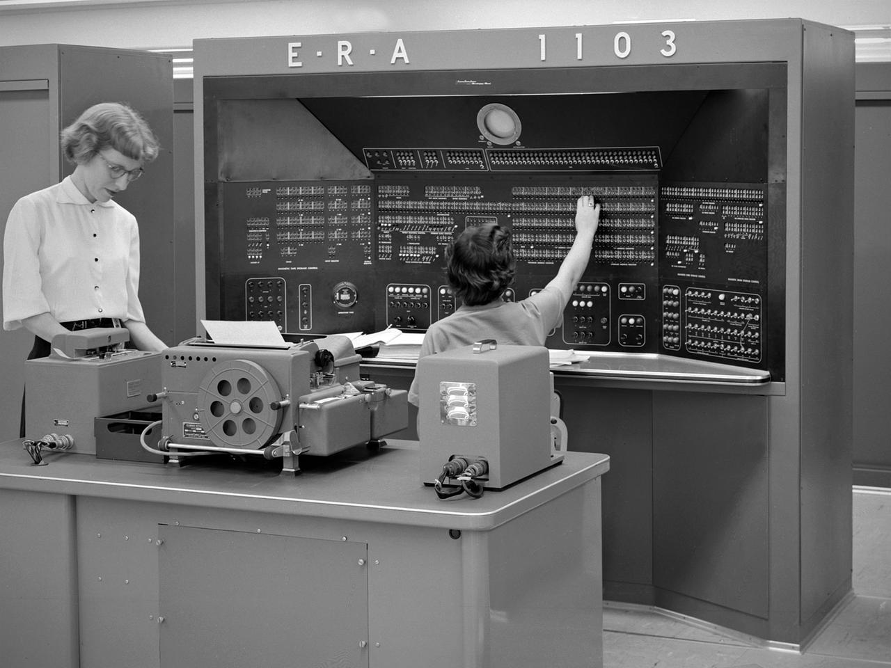
The new 10-by 10-Foot Supersonic Wind Tunnel at the Lewis Flight Propulsion Laboratory included high tech data acquisition and analysis systems. The reliable gathering of pressure, speed, temperature, and other data from test runs in the facilities was critical to the research process. Throughout the 1940s and early 1950s female employees, known as computers, recorded all test data and performed initial calculations by hand. The introduction of punch card computers in the late 1940s gradually reduced the number of hands-on calculations. In the mid-1950s new computational machines were installed in the office building of the 10-by 10-Foot tunnel. The new systems included this UNIVAC 1103 vacuum tube computer—the lab’s first centralized computer system. The programming was done on paper tape and fed into the machine. The 10-by 10 computer center also included the Lewis-designed Computer Automated Digital Encoder (CADDE) and Digital Automated Multiple Pressure Recorder (DAMPR) systems which converted test data to binary-coded decimal numbers and recorded test pressures automatically, respectively. The systems primarily served the 10-by 10, but were also applied to the other large facilities. Engineering Research Associates (ERA) developed the initial UNIVAC computer for the Navy in the late 1940s. In 1952 the company designed a commercial version, the UNIVAC 1103. The 1103 was the first computer designed by Seymour Cray and the first commercially successful computer.
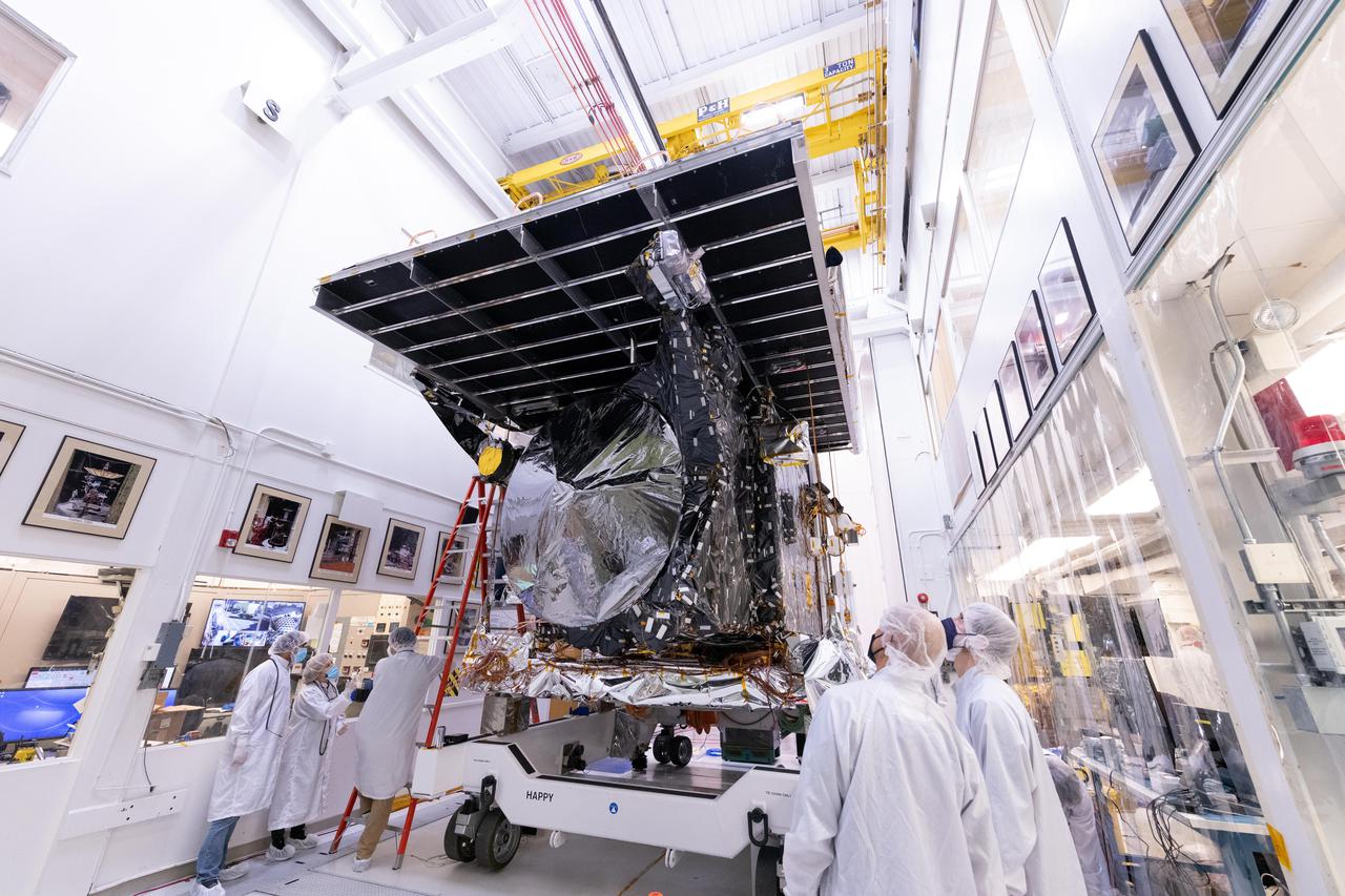
NASA's Psyche spacecraft is seen in early 2022 on its way to the vacuum chamber at the agency's Jet Propulsion Laboratory in Southern California. Thermal-vacuum (TVAC) testing is part of a regimen of environmental tests that are crucial for ensuring the spacecraft can survive the extreme conditions of launch and outer space. The orbiter will travel 1.5 billion miles (2.4 billion kilometers) to its target in the main asteroid belt, a metal-rich asteroid also called Psyche. Scientists believe the asteroid could be part or all of the iron-rich interior of an early planetary building block that was stripped of its outer rocky shell in the early days of the solar system. Over 18 days of TVAC testing, engineers exposed the spacecraft to the coldest and warmest conditions it will experience in flight, to prove that it is capable of regulating its own temperature. All of the air was sucked out of the chamber to replicate the airless vacuum of space. This test ensures that the spacecraft can survive the vacuum of space, and it helps engineers see how the spacecraft heats and cools itself without the movement of air to help it regulate temperature. Psyche is set to launch in August 2022. https://photojournal.jpl.nasa.gov/catalog/PIA25231
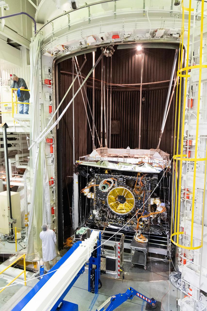
NASA's Psyche spacecraft is seen in early 2022 as it is placed in the 85-foot-tall, 25-foot-wide (26-meter-by-8-meter) ultra-sturdy vacuum chamber at the agency's Jet Propulsion Laboratory in Southern California. Thermal-vacuum (TVAC) testing is part of a regimen of environmental tests that are crucial for ensuring the spacecraft can survive the extreme conditions of launch and outer space. The orbiter will travel 1.5 billion miles (2.4 billion kilometers) to its target in the main asteroid belt, a metal-rich asteroid also called Psyche. Scientists believe the asteroid could be part or all of the iron-rich interior of an early planetary building block that was stripped of its outer rocky shell in the early days of the solar system. Over 18 days of TVAC testing, engineers exposed the spacecraft to the coldest and warmest conditions it will experience in flight, to prove that it is capable of regulating its own temperature. All of the air was sucked out of the chamber to replicate the airless vacuum of space. This test ensures that the spacecraft can survive the vacuum of space, and it helps engineers see how the spacecraft heats and cools itself without the movement of air to help it regulate temperature. Psyche is set to launch in August 2022. https://photojournal.jpl.nasa.gov/catalog/PIA25232
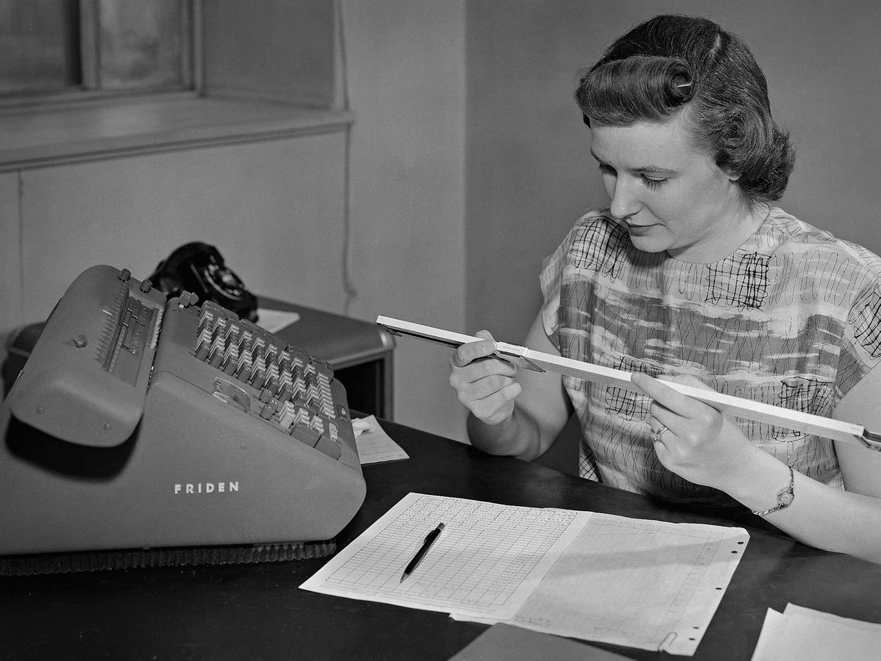
A female computer at the National Advisory Committee for Aeronautics (NACA) Lewis Flight Propulsion Laboratory with a slide rule and Friden adding machine to make computations. The computer staff was introduced during World War II to relieve short-handed research engineers of some of the tedious computational work. The Computing Section was staffed by “computers,” young female employees, who often worked overnight when most of the tests were run. The computers obtained test data from the manometers and other instruments, made the initial computations, and plotted the data graphically. Researchers then analyzed the data and summarized the findings in a report or made modifications and ran the test again. There were over 400 female employees at the laboratory in 1944, including 100 computers. The use of computers was originally planned only for the duration of the war. The system was so successful that it was extended into the 1960s. The computers and analysts were located in the Altitude Wind Tunnel Shop and Office Building office wing during the 1940s and transferred to the new 8- by 6-Foot Supersonic Wind Tunnel in 1948.
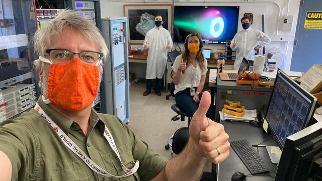
Psyche engineers adapted to COVID-19 social distancing and masking requirements while testing the Hall thrusters that will propel NASA's Psyche spacecraft on its journey to the main asteroid belt between Mars and Jupiter. Set to launch in August 2022, the spacecraft will utilize this super-efficient electric propulsion system to travel to the asteroid Psyche. On May 20, 2020, at NASA's Jet Propulsion Laboratory, Flight System Engineer Steve Snyder (foreground) of JPL and a crew of engineers from Maxar Technologies worked together in the control room next to the vacuum chamber where the thruster was fired up. Snyder and his Maxar colleagues (from left: Faraz Aghazadeh, Taylor Kerl and Giovanni Lenguito) put the thruster and its power supply through a series of stress tests to ensure they can operate together in the extreme conditions of deep space. In the background, a monitor projects the image of the thruster firing. The thruster works by turning xenon gas, a neutral gas used in car headlights and plasma TVs, into xenon ions. As the xenon ions are accelerated out of the thruster, they create the thrust that will propel the spacecraft. The xenon plasma emits a blue glow, seen here on the screen, as it operates. Hall thrusters will be used for the first time beyond lunar orbit, demonstrating that they could play a role in supporting future missions to deep space. Maxar and JPL adapted the Hall thruster system for use with the main body of the spacecraft that Maxar is building at its facility in Palo Alto, California. https://photojournal.jpl.nasa.gov/catalog/PIA23878
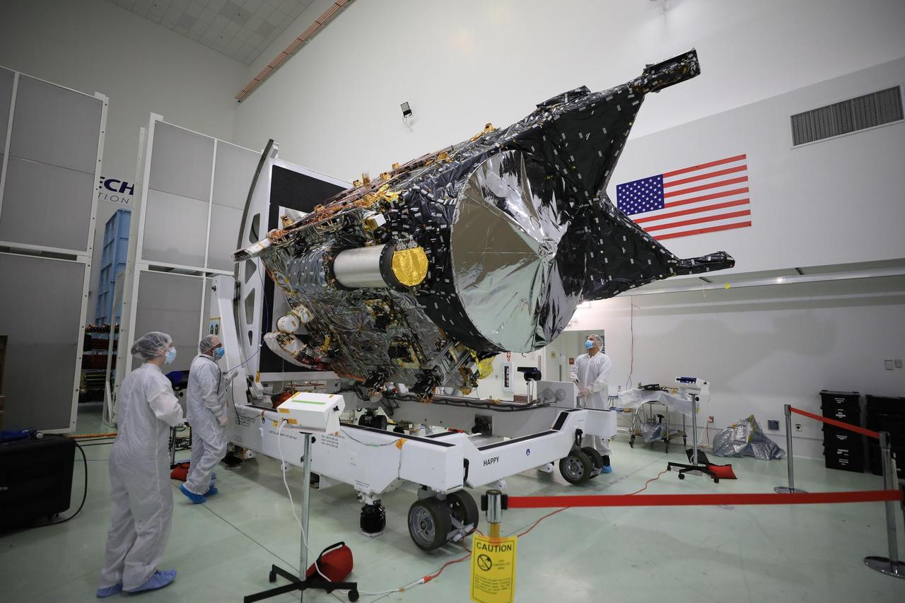
NASA's Psyche spacecraft is shown in a clean room on Dec. 8, 2022, at Astrotech Space Operations Facility near the agency's Kennedy Space Center in Florida. The spacecraft was powered on and connected to ground support equipment, enabling engineers and technicians to prepare it for launch in 2023. Teams working at Astrotech and at NASA's Jet Propulsion Laboratory in Southern California continue to monitor the health of its systems. After a one-year delay to complete critical testing, the Psyche project is targeting an October 2023 launch on a SpaceX Falcon Heavy rocket. NASA's Deep Space Optical Communications (DSOC) technology demonstration, testing high-data-rate laser communications, is integrated into Psyche and will travel with it when it launches to its target, a metal-rich asteroid, also named Psyche, that lies in the main asteroid belt. The silver-colored cylinder shown in the photo is the sunshade for DSOC, and the gold blanketing is the aperture cover for the DSOC payload. The spacecraft's target may be the partial core of a planetesimal, a building block of rocky planets in our solar system. Researchers will study Psyche using a suite of instruments including multispectral cameras, a Gamma Ray and Neutron Spectrometer (GRNS) and a magnetometer. The GRNS and magnetometer sensors are visible in the photo as the tips of the two black protrusions at the far end of the spacecraft. Also visible is the large, disc-shaped high-gain antenna, which will enable the spacecraft to communicate with Earth. https://photojournal.jpl.nasa.gov/catalog/PIA25664

A truck arrives at NASA's Jet Propulsion Laboratory in Southern California on June 3, 2024, to deliver the Medium Articulating Transportation System (MATS), which will be used during the construction and transportation of components for NASA's Near-Earth Object Surveyor mission. Originating at the aerospace company Beyond Gravity in Vienna, Austria, the MATS traveled via ship through the Panama Canal to Port Hueneme, California, before arriving by road at JPL. Construction has begun on NEO Surveyor's instrument enclosure in the High Bay 1 clean room at JPL's Spacecraft Assembly Facility. When the enclosure is complete later this year, it will be moved inside the MATS to NASA's Johnson Space Center in Houston for environmental testing. The MATS is a transportable clean room with its own filtration and climate control systems that keep the spacecraft and components clean, stable, and safe while being moved between facilities. NEO Surveyor's instrument enclosure contains the spacecraft's telescope, mirrors, and infrared sensors that will be used to detect, track, and characterize the most hazardous near-Earth objects. BAE Systems, Space Dynamics Laboratory, and Teledyne are among the aerospace and engineering companies contracted to build the spacecraft and its instrumentation. The Laboratory for Atmospheric and Space Physics at the University of Colorado, Boulder will support operations, and IPAC at Caltech in Pasadena, California, is responsible for processing survey data and producing the mission's data products. JPL manages the project; Caltech manages JPL for NASA. Launching no earlier than 2027, NEO Surveyor supports the objectives of NASA's Planetary Defense Coordination Office (PDCO) at NASA Headquarters in Washington. The NASA Authorization Act of 2005 directed NASA to discover and characterize at least 90% of the near-Earth objects more than 140 meters (460 feet) across that come within 30 million miles (48 million kilometers) of our planet's orbit. Objects of this size can cause significant regional damage, or worse, should they impact the Earth. https://photojournal.jpl.nasa.gov/catalog/PIA26381
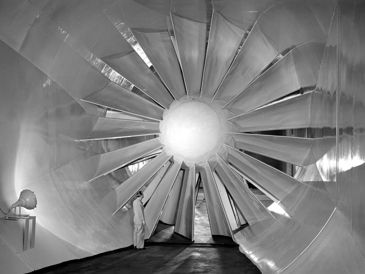
A researcher examines the drive fan inside the Icing Research Tunnel at the National Advisory Committee for Aeronautics (NACA) Flight Propulsion Research Laboratory in Cleveland, Ohio. The facility was built in the mid-1940s to simulate the atmospheric conditions that caused ice to build up on aircraft. Carrier Corporation refrigeration equipment reduced the internal air temperature to -45⁰ F, and a spray bar system injected water droplets into the air stream. The 24-foot diameter drive fan, seen in this photograph, created air flow velocities up to 400 miles per hour. The 1950s were prime years for the Icing Research Tunnel. NACA engineers had spent the 1940s trying to resolve the complexities of the spray bar system. The final system put into operation in 1950 included six horizontal spray bars with 80 nozzles that produced a 4- by 4-foot cloud in the test section. The icing tunnel was used for extensive testing of civilian and military aircraft components in the 1950s. The NACA also launched a major investigation of the various methods of heating leading edge surfaces. The hot-air anti-icing technology used on today’s commercial transports was largely developed in the facility during this period. Lewis researchers also made significant breakthroughs with icing on radomes and jet engines. Although the Icing Research Tunnel yielded major breakthroughs in the 1950s, the Lewis icing research program began tapering off as interest in the space program grew. The icing tunnel’s use declined in 1956 and 1957. The launch of Sputnik in October 1957 signaled the end of the facility’s operation. The icing staff was transferred to other research projects and the icing tunnel was temporarily mothballed.

At NASA's Jet Propulsion Laboratory in Southern California, on June 7, 2024, clean room technicians use a crane to lift the lid of the Medium Articulating Transportation System (MATS) that will be used during the construction and transportation of components for NASA's Near-Earth Object Surveyor mission. Inside the MATS is the Medium Articulating Assembly Dolly (MAAD), a platform that will support the spacecraft's instrument enclosure, which is being constructed inside the High Bay 1 clean room at JPL's Spacecraft Assembly Facility. The MAAD is an articulating platform on which a spacecraft (or spacecraft components) can be mounted securely and positioned as required during assembly. It can tilt a spacecraft vertically and horizontally, rotating it 360 degrees. JPL plans to use the MAAD for future missions to reduce the number of crane lifts during assembly, test, and launch operations, known as ATLO. NEO Surveyor is the first mission to use the platform. NEO Surveyor's instrument enclosure contains the spacecraft's telescope, mirrors, and infrared sensors that will be used to detect, track, and characterize the most hazardous near-Earth objects. BAE Systems, Space Dynamics Laboratory, and Teledyne are among the aerospace and engineering companies contracted to build the spacecraft and its instrumentation. The Laboratory for Atmospheric and Space Physics at the University of Colorado, Boulder will support operations, and IPAC at Caltech in Pasadena, California, is responsible for processing survey data and producing the mission's data products. JPL manages the project; Caltech manages JPL for NASA. Launching no earlier than 2027, NEO Surveyor supports the objectives of NASA's Planetary Defense Coordination Office (PDCO) at NASA Headquarters in Washington. The NASA Authorization Act of 2005 directed NASA to discover and characterize at least 90% of the near-Earth objects more than 140 meters (460 feet) across that come within 30 million miles (48 million kilometers) of our planet's orbit. Objects of this size can cause significant regional damage, or worse, should they impact the Earth. https://photojournal.jpl.nasa.gov/catalog/PIA26382