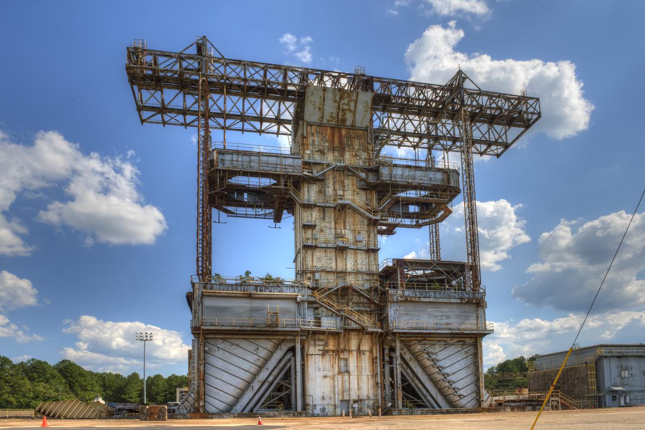
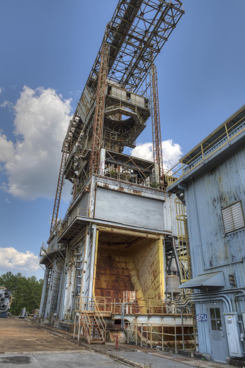
PROPULSION AND STRUCTURAL TEST FACILITY (BUILDING 4572) AT THE GEORGE C. MARSHALL SPACE FLIGHT CENTER IN HUNTSVILLE, ALABAMA
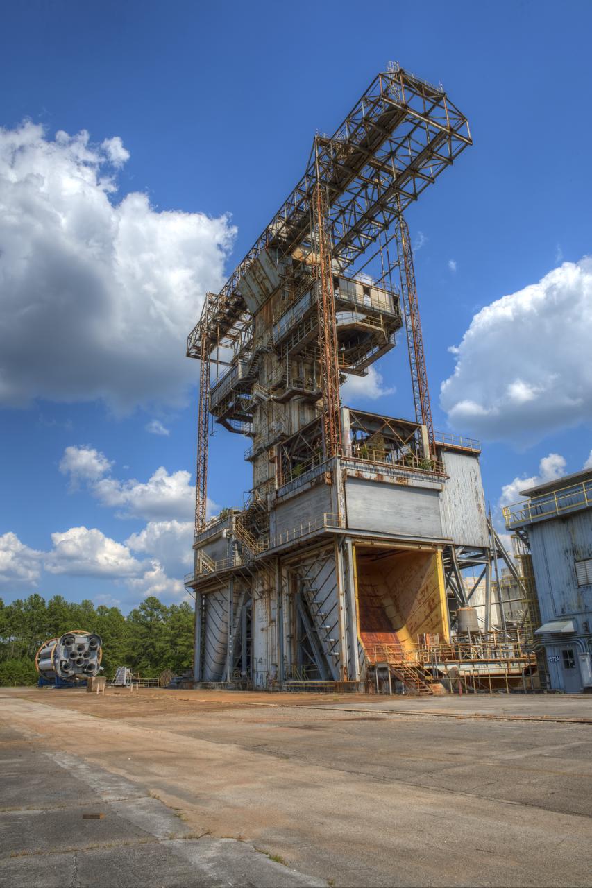
PROPULSION AND STRUCTURAL TEST FACILITY (BUILDING 4572) AT THE GEORGE C. MARSHALL SPACE FLIGHT CENTER IN HUNTSVILLE, ALABAMA
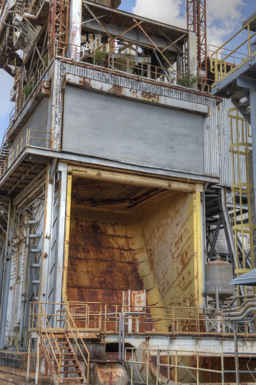
PROPULSION AND STRUCTURAL TEST FACILITY (BUILDING 4572) AT THE GEORGE C. MARSHALL SPACE FLIGHT CENTER IN HUNTSVILLE, ALABAMA
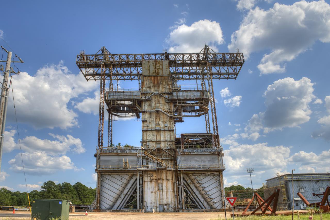
PROPULSION AND STRUCTURAL TEST FACILITY (BUILDING 4572) AT THE GEORGE C. MARSHALL SPACE FLIGHT CENTER IN HUNTSVILLE, ALABAMA
PROPULSION AND STRUCTURAL TEST FACILITY (BUILDING 4572) AT THE GEORGE C. MARSHALL SPACE FLIGHT CENTER IN HUNTSVILLE, ALABAMA
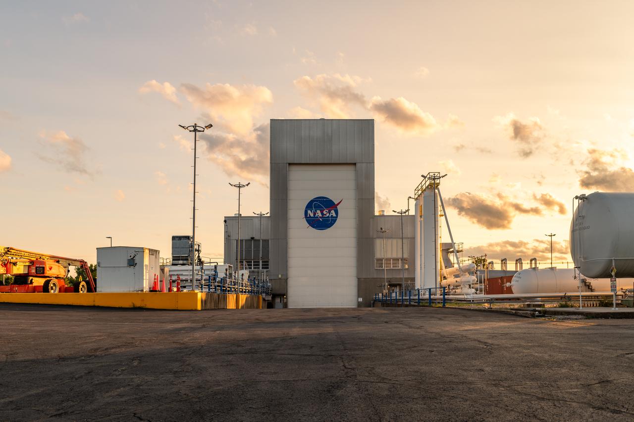
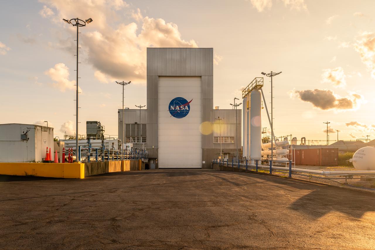
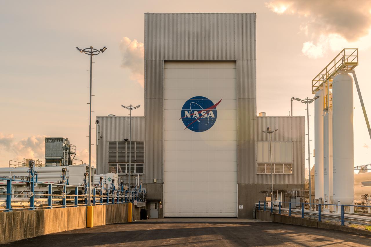
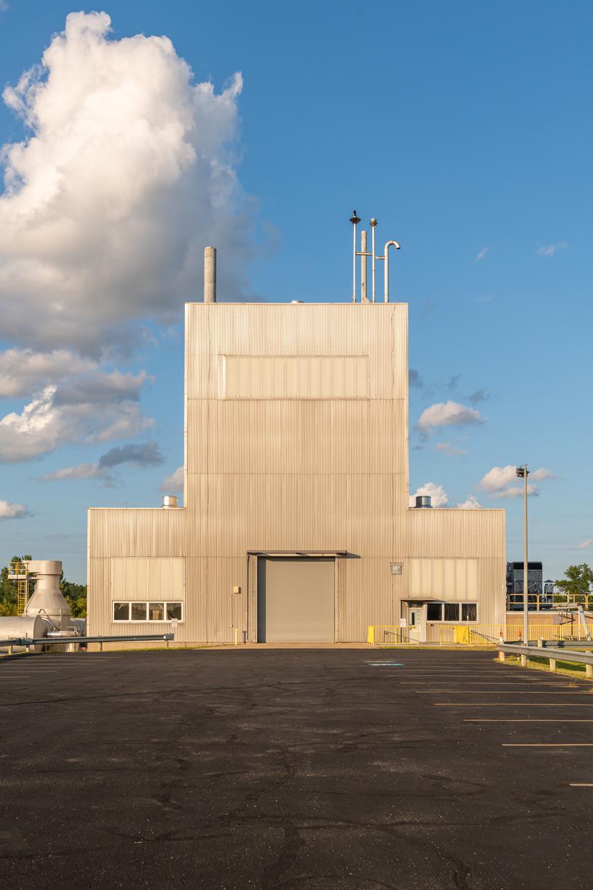
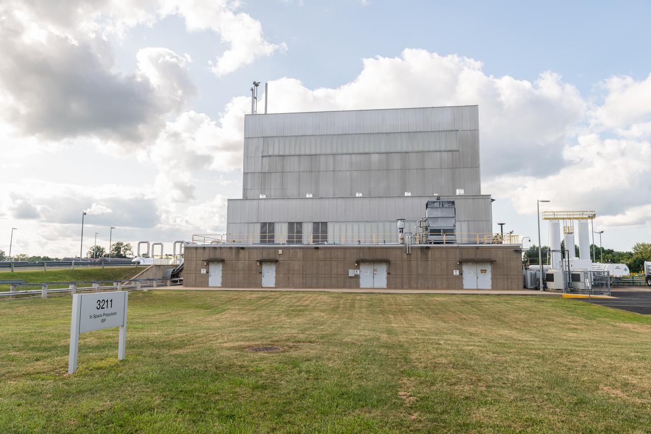
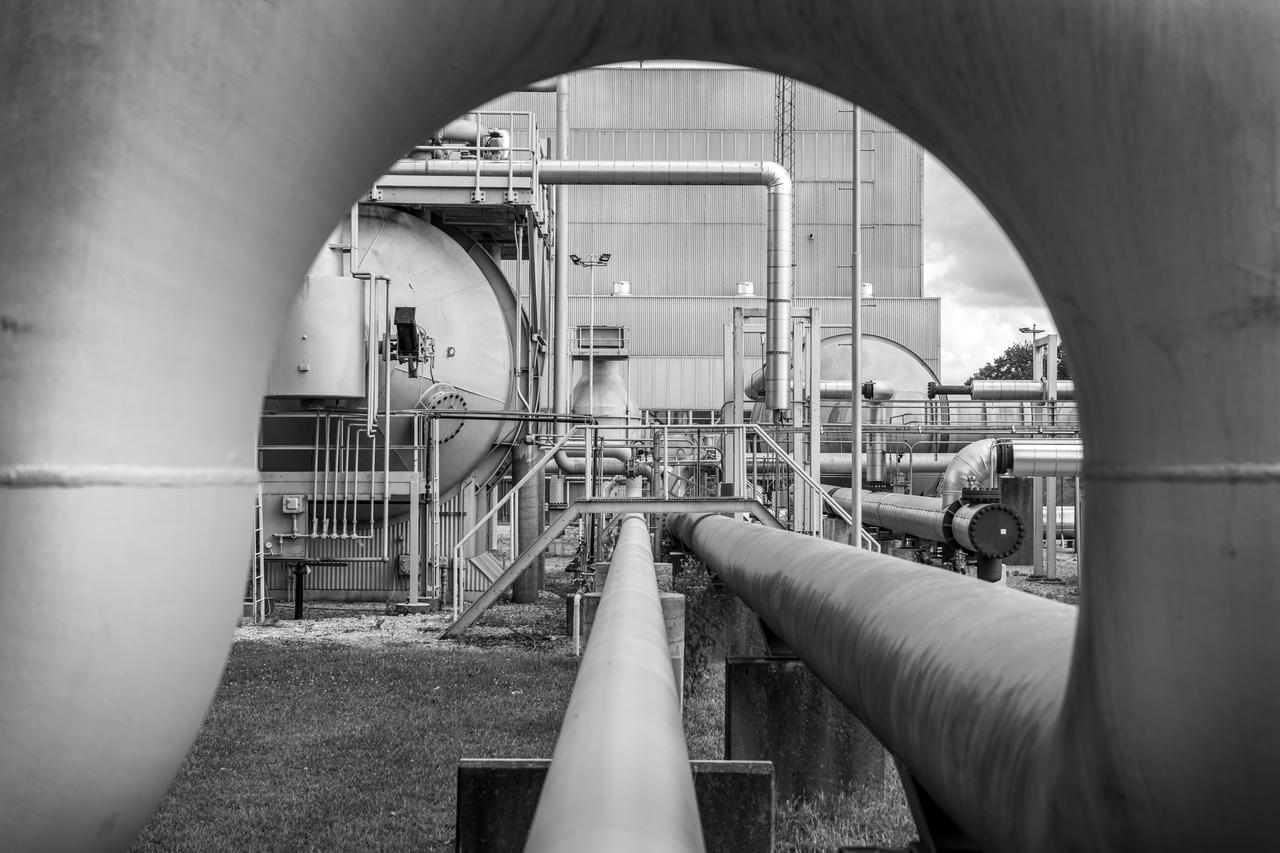
NASA’s In-Space Propulsion Facility located at Neil Armstrong Test Facility in Sandusky Ohio is the world’s only high altitude test facility capable of full-scale rocket engine and launch vehicle system level tests. The facility supports mission profile thermal vacuum simulation and engine firing. The engine or vehicle can be exposed for indefinite periods to low ambient pressures, low-background temperatures, and dynamic solar heating, simulating the environment the hardware will encounter during orbital or interplanetary travel. Photo Credit: (NASA/Jordan Salkin)
NASA’s In-Space Propulsion Facility located at Neil Armstrong Test Facility in Sandusky Ohio is the world’s only high altitude test facility capable of full-scale rocket engine and launch vehicle system level tests. The facility supports mission profile thermal vacuum simulation and engine firing. The engine or vehicle can be exposed for indefinite periods to low ambient pressures, low-background temperatures, and dynamic solar heating, simulating the environment the hardware will encounter during orbital or interplanetary travel. Photo Credit: (NASA/Jordan Salkin)
NASA’s In-Space Propulsion Facility located at Neil Armstrong Test Facility in Sandusky Ohio is the world’s only high altitude test facility capable of full-scale rocket engine and launch vehicle system level tests. The facility supports mission profile thermal vacuum simulation and engine firing. The engine or vehicle can be exposed for indefinite periods to low ambient pressures, low-background temperatures, and dynamic solar heating, simulating the environment the hardware will encounter during orbital or interplanetary travel. Photo Credit: (NASA/Jordan Salkin)
NASA’s In-Space Propulsion Facility located at Neil Armstrong Test Facility in Sandusky Ohio is the world’s only high altitude test facility capable of full-scale rocket engine and launch vehicle system level tests. The facility supports mission profile thermal vacuum simulation and engine firing. The engine or vehicle can be exposed for indefinite periods to low ambient pressures, low-background temperatures, and dynamic solar heating, simulating the environment the hardware will encounter during orbital or interplanetary travel. Photo Credit: (NASA/Jordan Salkin)
NASA’s In-Space Propulsion Facility located at Neil Armstrong Test Facility in Sandusky Ohio is the world’s only high altitude test facility capable of full-scale rocket engine and launch vehicle system level tests. The facility supports mission profile thermal vacuum simulation and engine firing. The engine or vehicle can be exposed for indefinite periods to low ambient pressures, low-background temperatures, and dynamic solar heating, simulating the environment the hardware will encounter during orbital or interplanetary travel. Photo Credit: (NASA/Jordan Salkin)
NASA’s In-Space Propulsion Facility located at Neil Armstrong Test Facility in Sandusky Ohio is the world’s only high altitude test facility capable of full-scale rocket engine and launch vehicle system level tests. The facility supports mission profile thermal vacuum simulation and engine firing. The engine or vehicle can be exposed for indefinite periods to low ambient pressures, low-background temperatures, and dynamic solar heating, simulating the environment the hardware will encounter during orbital or interplanetary travel. Photo Credit: (NASA/Jordan Salkin)
NASA’s In-Space Propulsion Facility located at Neil Armstrong Test Facility in Sandusky Ohio is the world’s only high altitude test facility capable of full-scale rocket engine and launch vehicle system level tests. The facility supports mission profile thermal vacuum simulation and engine firing. The engine or vehicle can be exposed for indefinite periods to low ambient pressures, low-background temperatures, and dynamic solar heating, simulating the environment the hardware will encounter during orbital or interplanetary travel. Photo Credit: (NASA/Jordan Salkin)
NASA’s In-Space Propulsion Facility located at Neil Armstrong Test Facility in Sandusky Ohio is the world’s only high altitude test facility capable of full-scale rocket engine and launch vehicle system level tests. The facility supports mission profile thermal vacuum simulation and engine firing. The engine or vehicle can be exposed for indefinite periods to low ambient pressures, low-background temperatures, and dynamic solar heating, simulating the environment the hardware will encounter during orbital or interplanetary travel. Photo Credit: (NASA/Jordan Salkin)
NASA’s In-Space Propulsion Facility located at Neil Armstrong Test Facility in Sandusky Ohio is the world’s only high altitude test facility capable of full-scale rocket engine and launch vehicle system level tests. The facility supports mission profile thermal vacuum simulation and engine firing. The engine or vehicle can be exposed for indefinite periods to low ambient pressures, low-background temperatures, and dynamic solar heating, simulating the environment the hardware will encounter during orbital or interplanetary travel. Photo Credit: (NASA/Jordan Salkin)
NASA’s In-Space Propulsion Facility located at Neil Armstrong Test Facility in Sandusky Ohio is the world’s only high altitude test facility capable of full-scale rocket engine and launch vehicle system level tests. The facility supports mission profile thermal vacuum simulation and engine firing. The engine or vehicle can be exposed for indefinite periods to low ambient pressures, low-background temperatures, and dynamic solar heating, simulating the environment the hardware will encounter during orbital or interplanetary travel. Photo Credit: (NASA/Jordan Salkin)
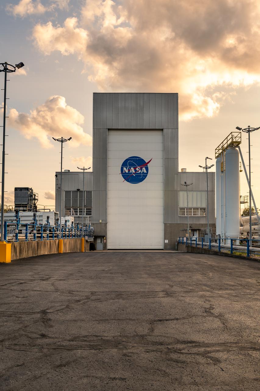
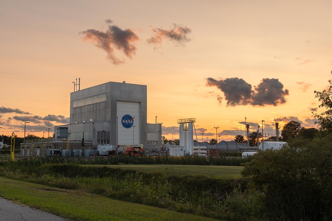
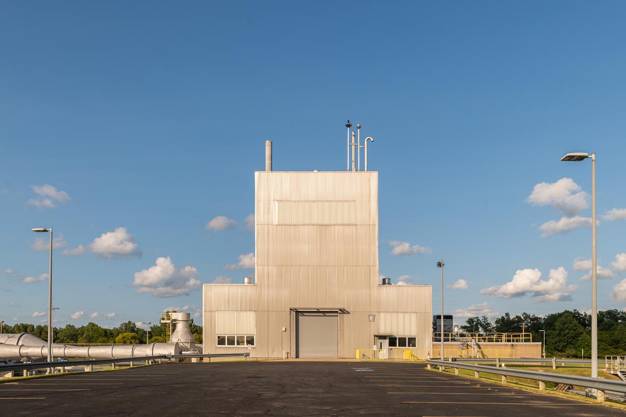
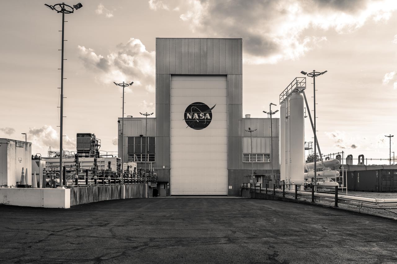
The In-Space Propulsion Facility (ISP) is shown at NASA’s Neil Armstrong Test Facility in Sandusky, Ohio. ISP is the world’s only facility capable of full-scale rocket engine and launch vehicle system level tests. Photo Credit: (NASA/Jordan Salkin)
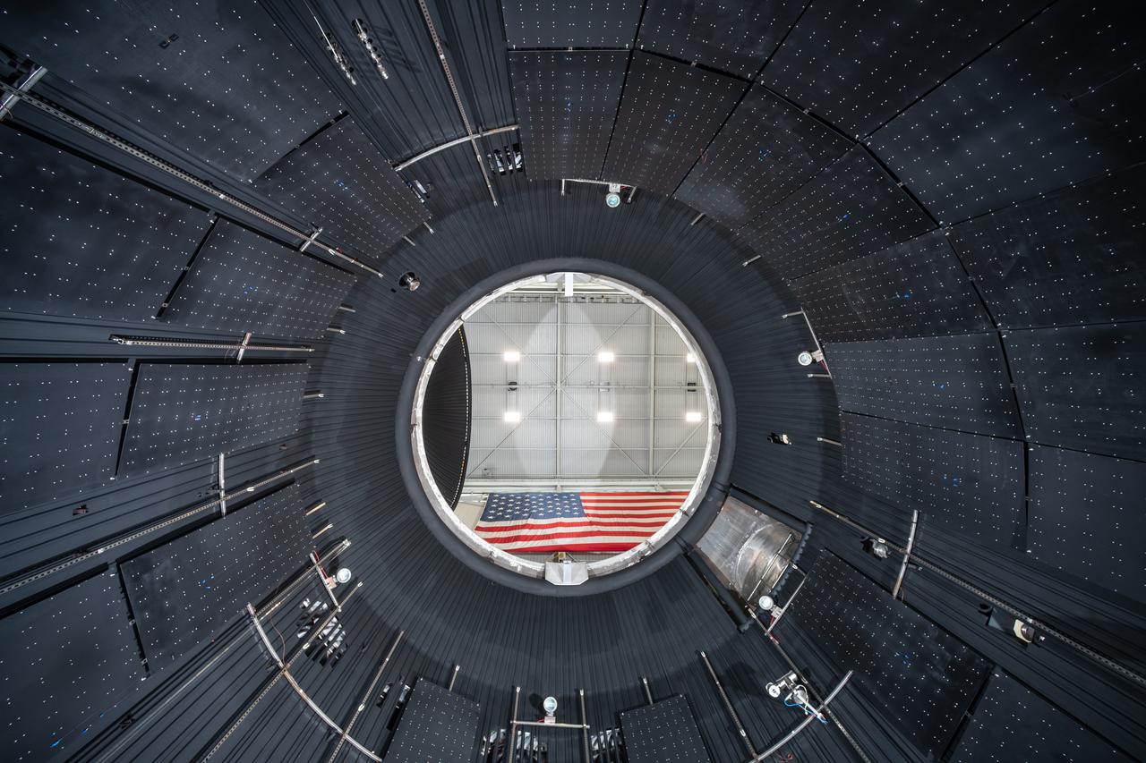
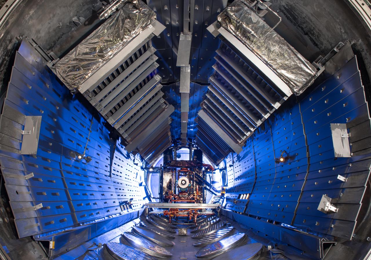
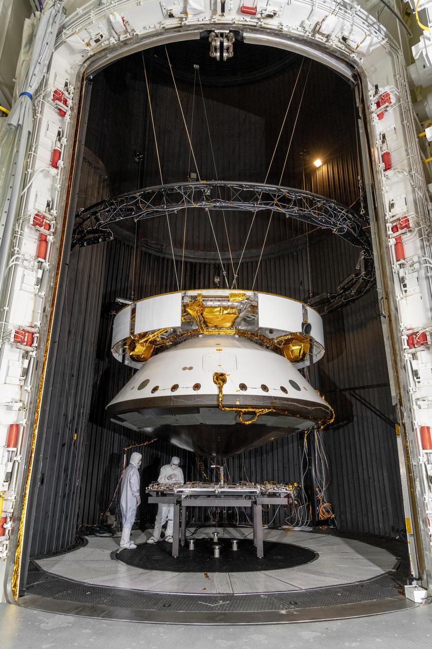
The vacuum chamber of the In-Space Propulsion (ISP) facility at the Neil Armstrong Test Facility spans 38ft in diameter and is 62ft tall. ISP is the world’s only facility capable of full-scale rocket engine and launch vehicle system level tests. ISP also has a vacuum range of up to 100 statute miles in altitude. This is a view from inside the chamber. Photo Credit: (NASA/Jordan Salkin)
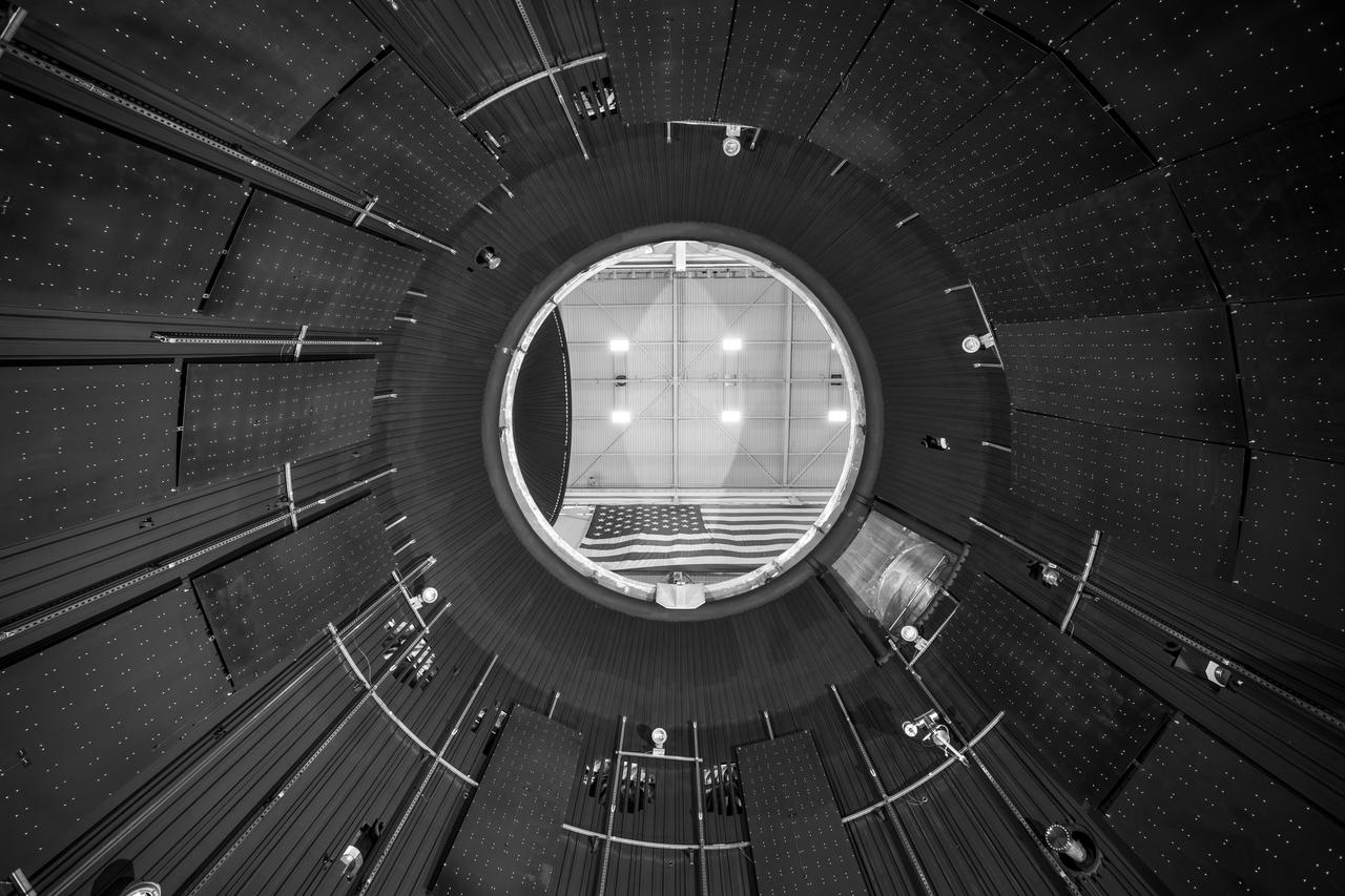
NASA’s In-Space Propulsion Facility located at Neil Armstrong Test Facility in Sandusky Ohio is the world’s only high altitude test facility capable of full-scale rocket engine and launch vehicle system level tests. The facility supports mission profile thermal vacuum simulation and engine firing. The engine or vehicle can be exposed for indefinite periods to low ambient pressures, low-background temperatures, and dynamic solar heating, simulating the environment the hardware will encounter during orbital or interplanetary travel. This is a view from inside the chamber looking up toward the American flag. Photo Credit: (NASA/Jordan Salkin)
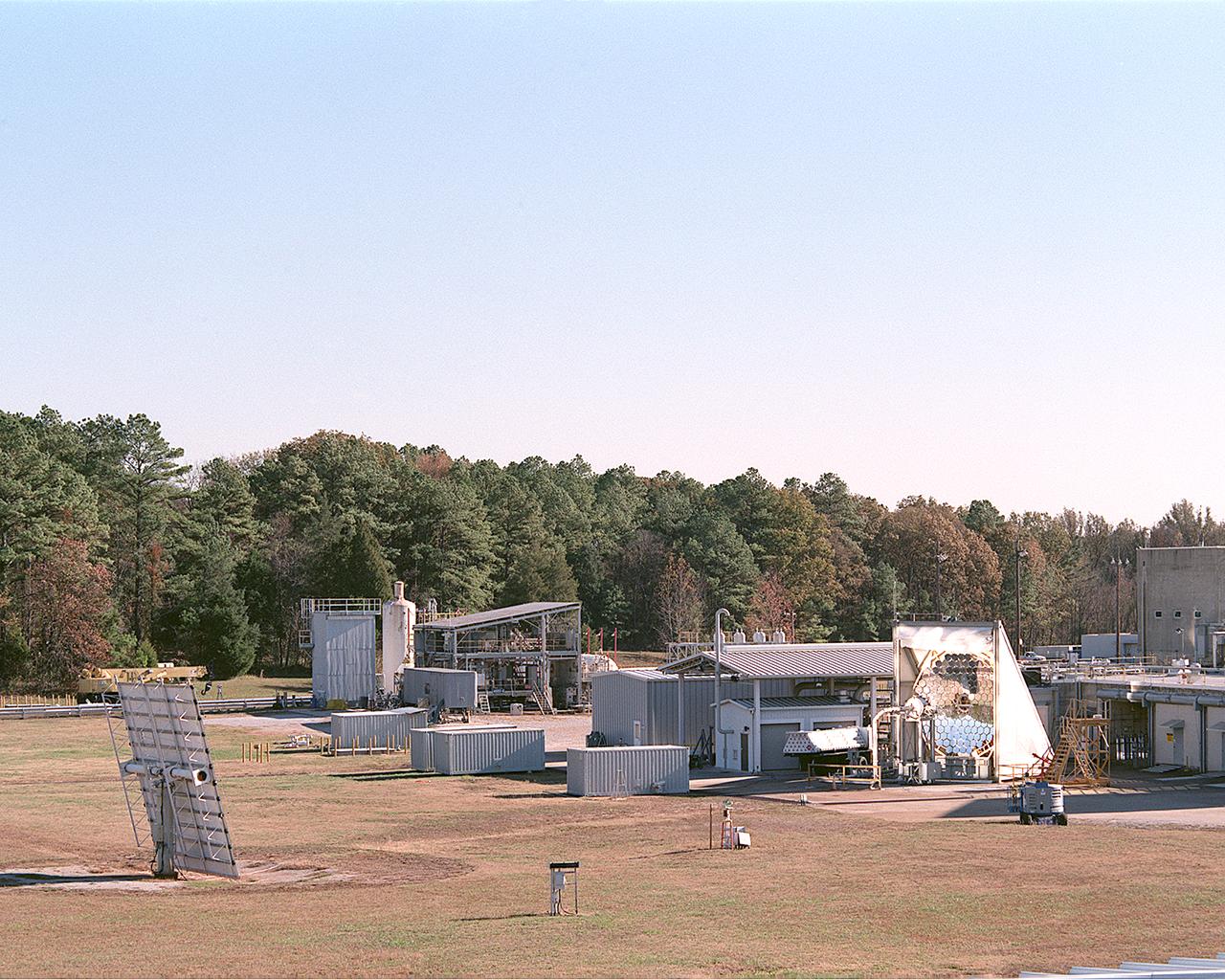
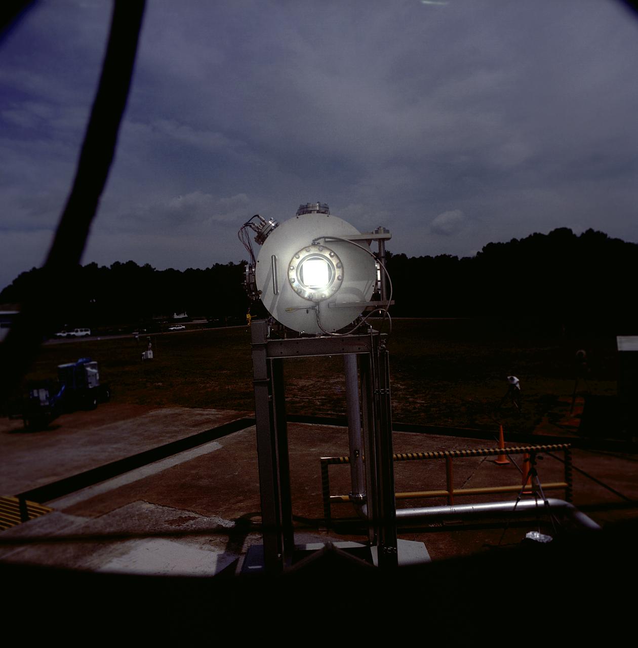
This photograph shows an overall view of the Solar Thermal Propulsion Test Facility at the Marshall Space Flight Center (MSFC). The 20-by 24-ft heliostat mirror, shown at the left, has dual-axis control that keeps a reflection of the sunlight on an 18-ft diameter concentrator mirror (right). The concentrator mirror then focuses the sunlight to a 4-in focal point inside the vacuum chamber, shown at the front of concentrator mirror. Researchers at MSFC have designed, fabricated, and tested the first solar thermal engine, a non-chemical rocket engine that produces lower thrust but has better thrust efficiency than chemical a combustion engine. MSFC turned to solar thermal propulsion in the early 1990s due to its simplicity, safety, low cost, and commonality with other propulsion systems. Solar thermal propulsion works by acquiring and redirecting solar energy to heat a propell nt. As part of MSFC's Space Transportation Directorate, the Propulsion Research Center serves as a national resource for research of advanced, revolutionary propulsion technologies. The mission is to move the Nation's capabilities beyond the confines of conventional chemical propulsion into an era of aircraft-like access to Earth-orbit, rapid travel throughout the solar system, and exploration of interstellar space.
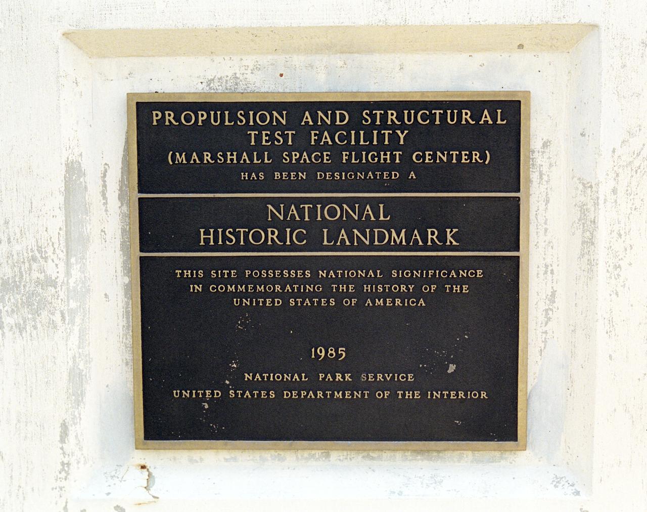
This plaque, displayed on the grounds of Marshall Space Flight Center in Huntsville, Alabama, commemorates the designation of the Propulsion and Structural Test Facility as a National Historic Landmark by the National Park Service of the United States Interior. The site was designated as a landmark in 1985.
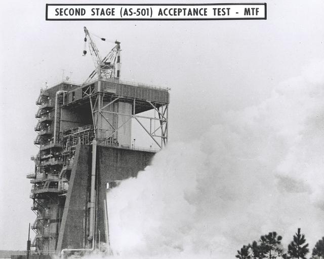
This photograph shows a test firing of a Saturn V second stage (S-II) on the S-IC test stand at the Propulsion Test Facility near New Orleans, Louisiana. This second stage component was used in the unmarned test flight of Apollo 4.
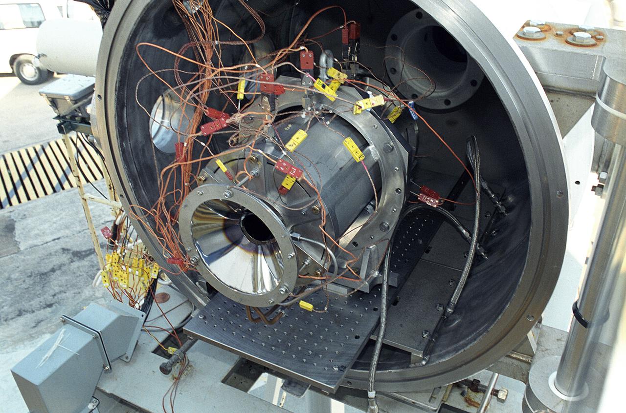
Researchers at the Marshall Space Flight Center (MSFC) have designed, fabricated, and tested the first solar thermal engine, a non-chemical rocket engine that produces lower thrust but has better thrust efficiency than a chemical combustion engine. MSFC turned to solar thermal propulsion in the early 1990s due to its simplicity, safety, low cost, and commonality with other propulsion systems. Solar thermal propulsion works by acquiring and redirecting solar energy to heat a propellant. This photograph shows a fully assembled solar thermal engine placed inside the vacuum chamber at the test facility prior to testing. The 20- by 24-ft heliostat mirror (not shown in this photograph) has a dual-axis control that keeps a reflection of the sunlight on the 18-ft diameter concentrator mirror, which then focuses the sunlight to a 4-in focal point inside the vacuum chamber. The focal point has 10 kilowatts of intense solar power. As part of MSFC's Space Transportation Directorate, the Propulsion Research Center serves as a national resource for research of advanced, revolutionary propulsion technologies. The mission is to move theNation's capabilities beyond the confines of conventional chemical propulsion into an era of aircraft-like access to Earth orbit, rapid travel throughout the solar system, and exploration of interstellar space.
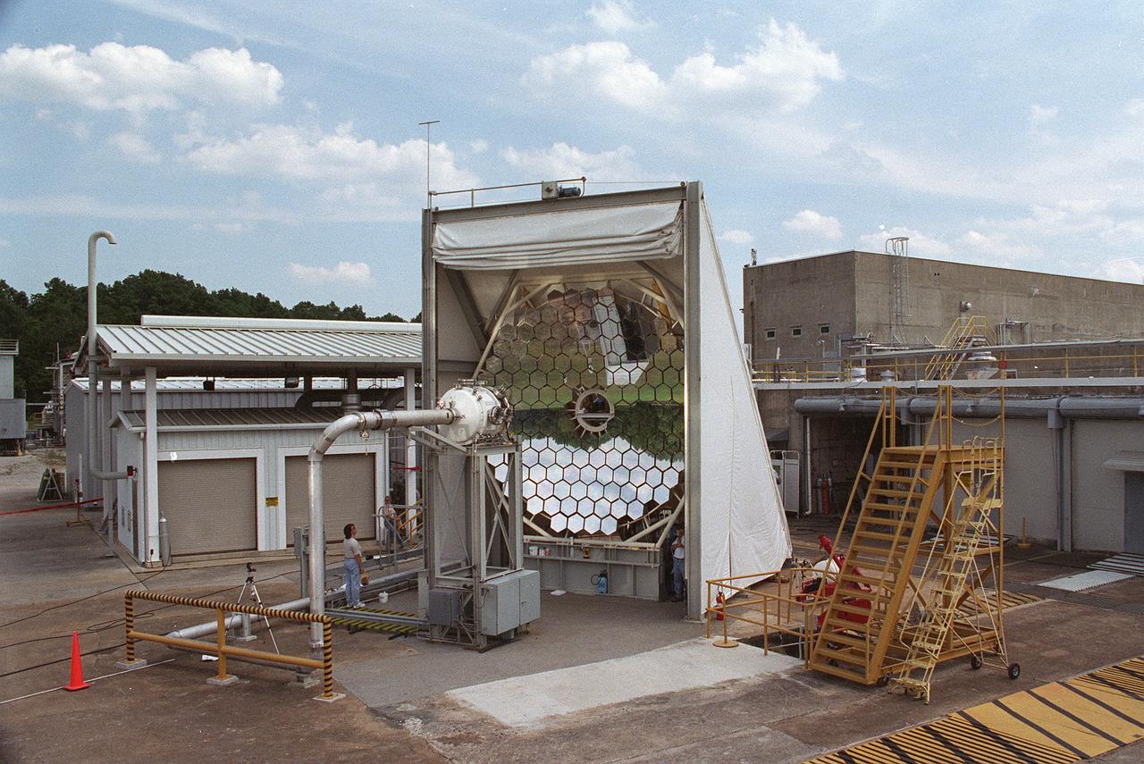
Researchers at the Marshall Space Flight Center (MSFC) have designed, fabricated and tested the first solar thermal engine, a non-chemical rocket engine that produces lower thrust but has better thrust efficiency than a chemical combustion engine. MSFC turned to solar thermal propulsion in the early 1990s due to its simplicity, safety, low cost, and commonality with other propulsion systems. Solar thermal propulsion works by acquiring and redirecting solar energy to heat a propellant. This photograph, taken at MSFC's Solar Thermal Propulsion Test Facility, shows a concentrator mirror, a combination of 144 mirrors forming this 18-ft diameter concentrator, and a vacuum chamber that houses the focal point. The 20- by 24-ft heliostat mirror (not shown in this photograph) has a dual-axis control that keeps a reflection of the sunlight on the 18-foot diameter concentrator mirror, which then focuses the sunlight to a 4-in focal point inside the vacuum chamber. The focal point has 10 kilowatts of intense solar power. As part of MSFC's Space Transportation Directorate, the Propulsion Research Center serves as a national resource for research of advanced, revolutionary propulsion technologies. The mission is to move the Nation's capabilities beyond the confines of conventional chemical propulsion into an era of aircraft-like access to Earth-orbit, rapid travel throughout the solar system, and exploration of interstellar space.
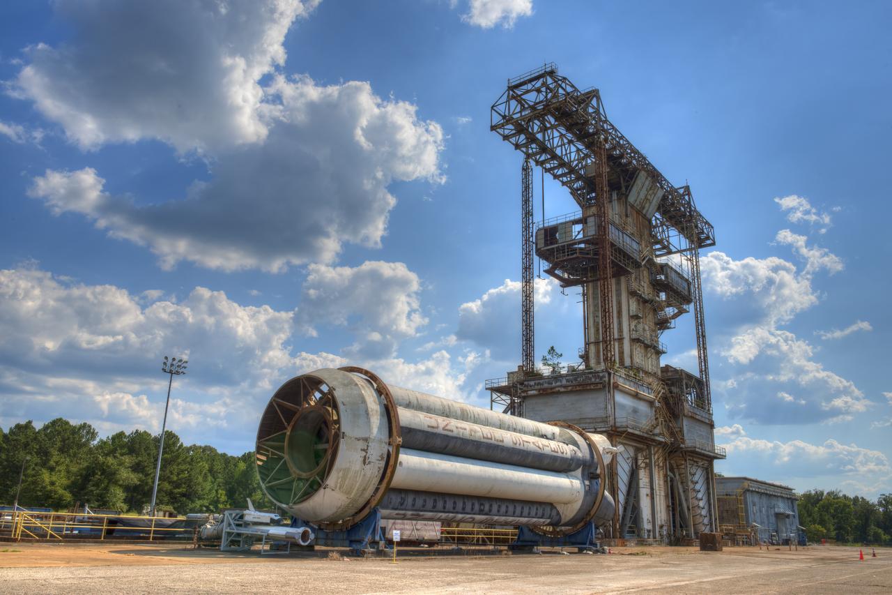
SATURN S-1B STAGE (SA-T) WITH PROPULSION AND STRUCTURAL TEST FACILITY (BUILDING 4572) IN BACKGROUND
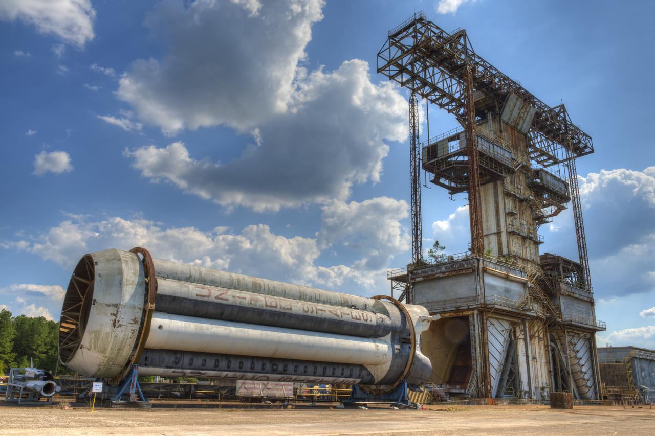
PROPULSION AND STRUCTURAL TEST FACILITY (BUILDING 4572) AT THE GEORGE C. MARSHALL SPACE FLIGHT CENTER IN HUNTSVILLE, ALABAMA WITH THE SATURN S-1B STAGE (SA-) IN FOREGROUND
Researchers at the Marshall Space Flight Center (MSFC) have designed, fabricated, and tested the first solar thermal engine, a non-chemical rocket engine that produces lower thrust but has better thrust efficiency than a chemical combustion engine. MSFC turned to solar thermal propulsion in the early 1990s due to its simplicity, safety, low cost, and commonality with other propulsion systems. Solar thermal propulsion works by acquiring and redirecting solar energy to heat a propellant. The 20- by 24-ft heliostat mirror (not shown in this photograph) has dual-axis control that keeps a reflection of the sunlight on an 18-ft diameter concentrator mirror, which then focuses the sunlight to a 4-in focal point inside the vacuum chamber. The focal point has 10 kilowatts of intense solar power. This photograph is a close-up view of a 4-in focal point inside the vacuum chamber at the MSFC Solar Thermal Propulsion Test facility. As part of MSFC's Space Transportation Directorate, the Propulsion Research Center serves as a national resource for research of advanced, revolutionary propulsion technologies. The mission is to move the Nation's capabilities beyond the confines of conventional chemical propulsion into an era of aircraft-like access to Earth orbit, rapid travel throughout the solar system, and exploration of interstellar space.
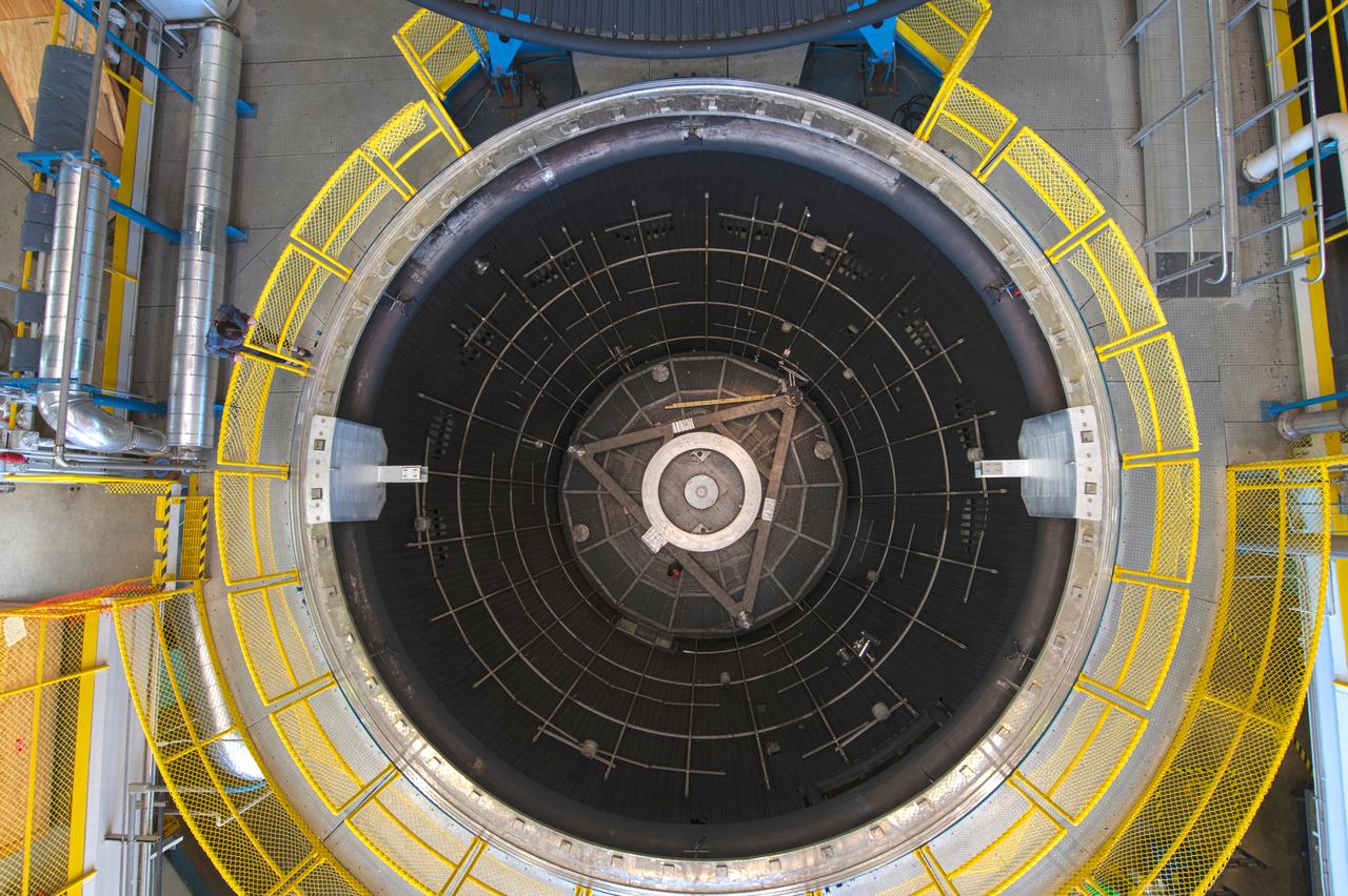
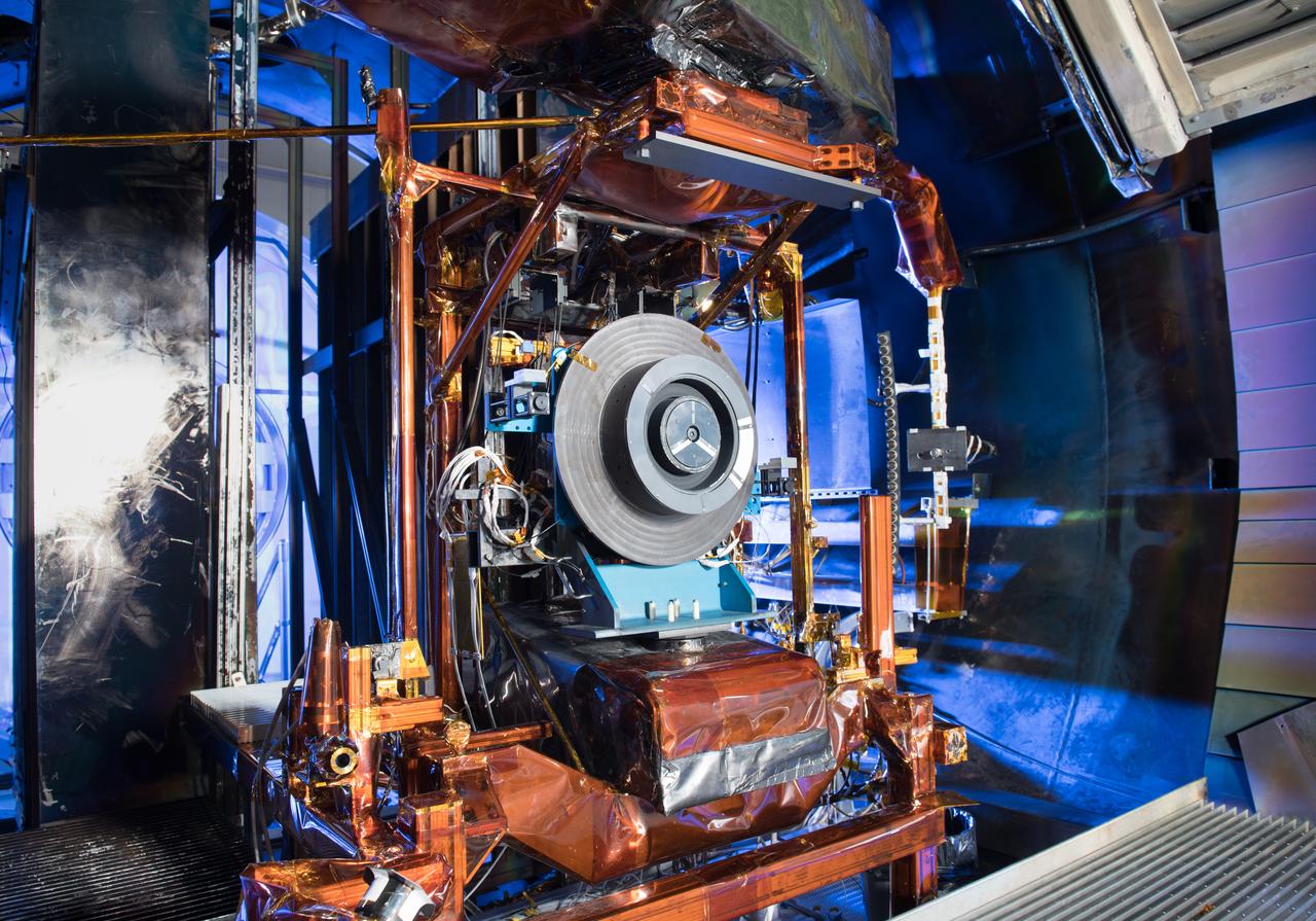
The test chamber is 38 ft in diameter by 62 ft deep amd made of stainless steel. It is vacuum rated at 10-7 torr long duration (Local atmospheric pressure to 100 statute miles altitude). The vacuum chamber surfaces are lined with a liquid nitrogen cold wall, capable of maintaining -320 °F. A quartz infrared heating system can be programmed to radiate a sinusoidal distribution, simulating rotational solar heating. Photo Credit: (NASA/Quentin Schwinn)

The Sierra Space Plane, Dream Chaser, suspended by a crane sits just inside the overhead door of the ISP (In Space Propulsion) test facility at NASA GRC-ATF. Once lifted and lowered into the test chamber, it will be exposed to the harsh cold conditions of space for testing in extended periods of time.
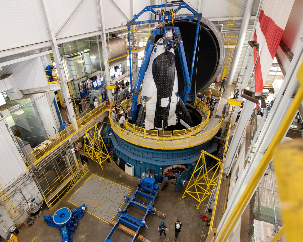
Sierra Space Dream Chaser space plane is lifted into the chamber at ISP (In Space Propulsion) facility, building 3211 at ATF (Armstrong Test Facility) for environmental testing. Once lowered into the test chamber, it will be exposed to the harsh cold conditions of space for extended periods of time.
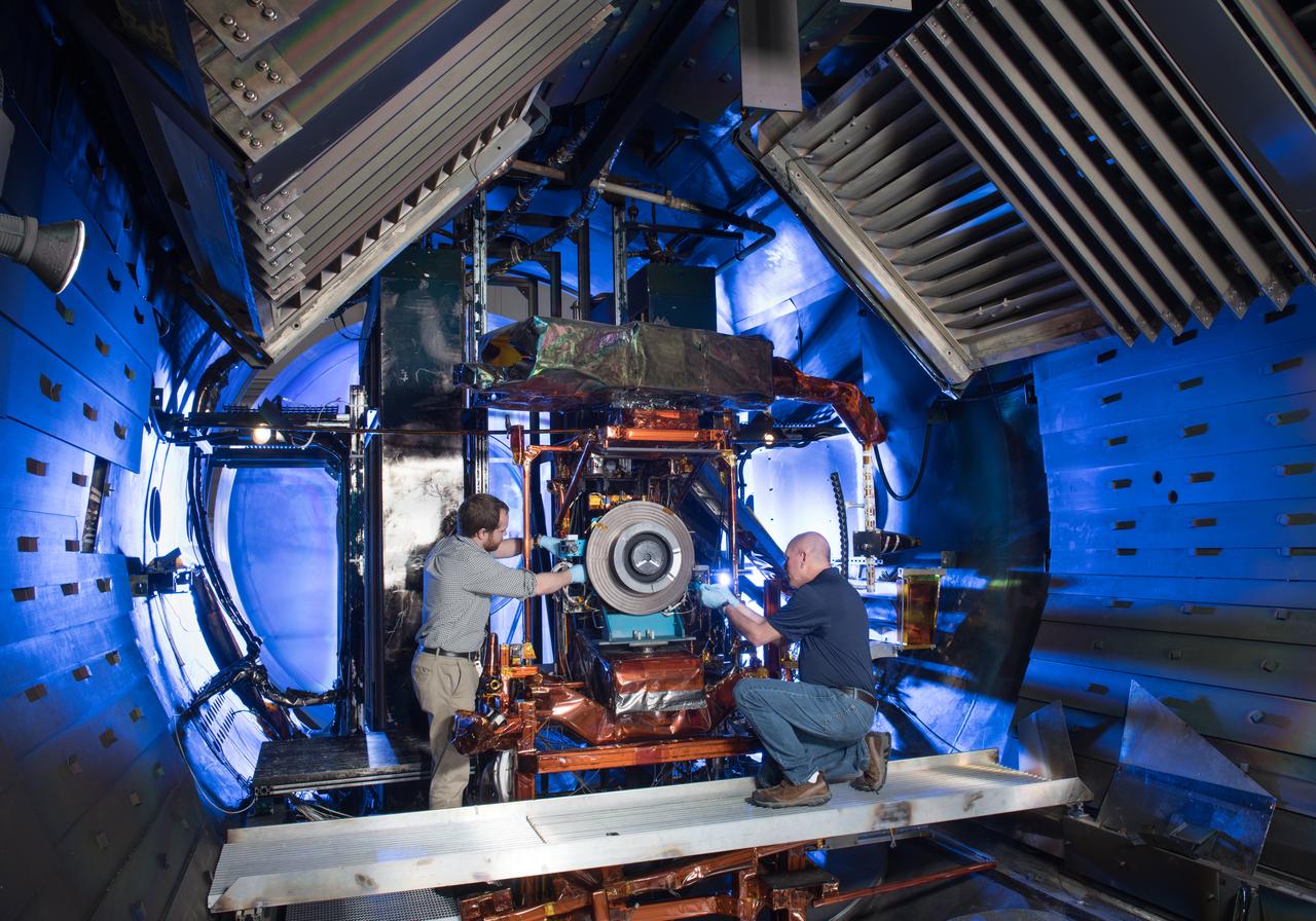
Advanced Electric Propulsion Systems Contract, Technology Demonstration Unit, TDU-3 Checkout Test Hardware Installed in Vacuum Facility 5, VF-5
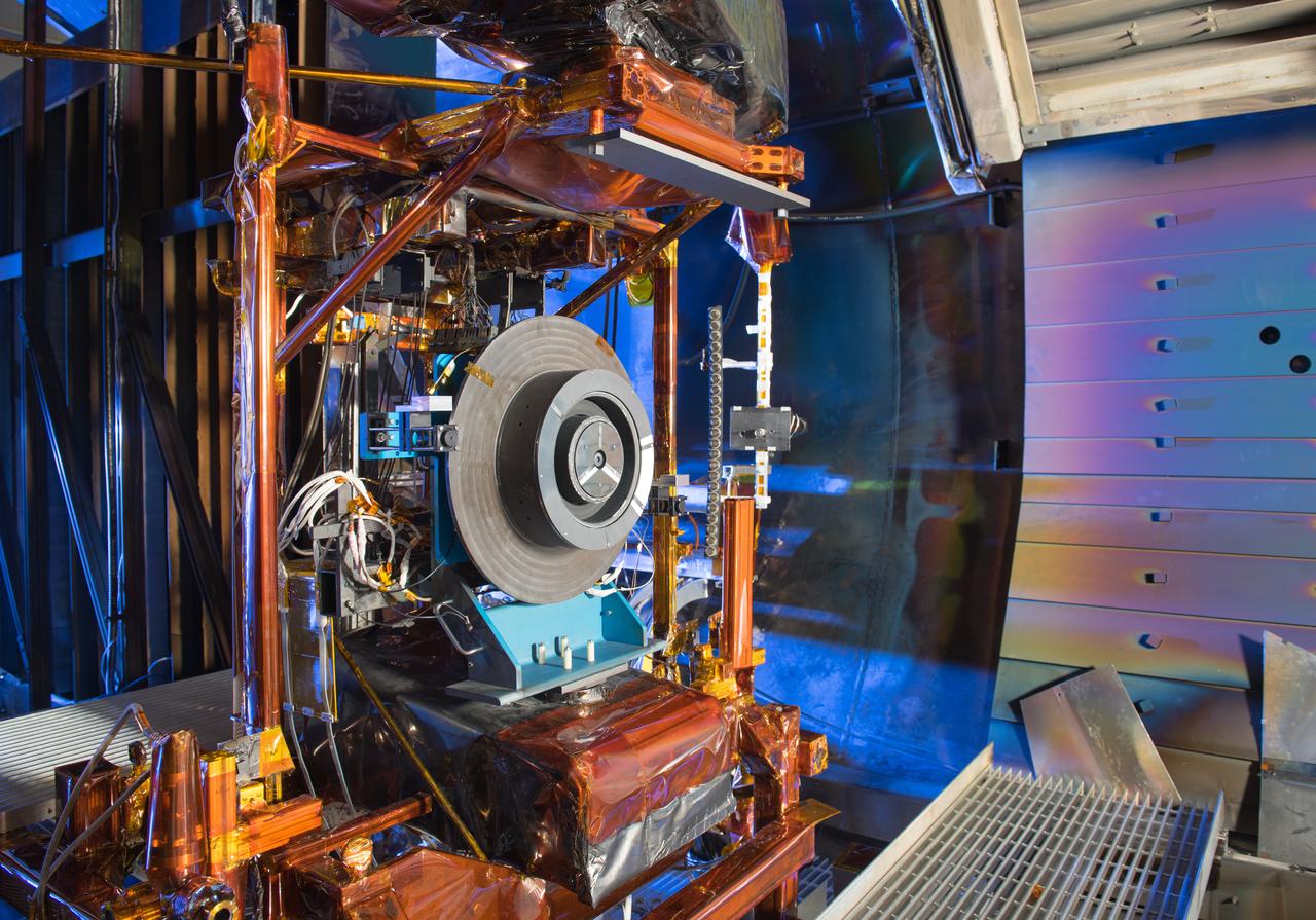
Advanced Electric Propulsion Systems Contract, Technology Demonstration Unit, TDU-3 Checkout Test Hardware Installed in Vacuum Facility 5, VF-5
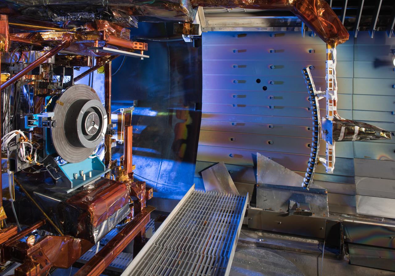
Advanced Electric Propulsion Systems Contract, Technology Demonstration Unit, TDU-3 Checkout Test Hardware Installed in Vacuum Facility 5, VF-5
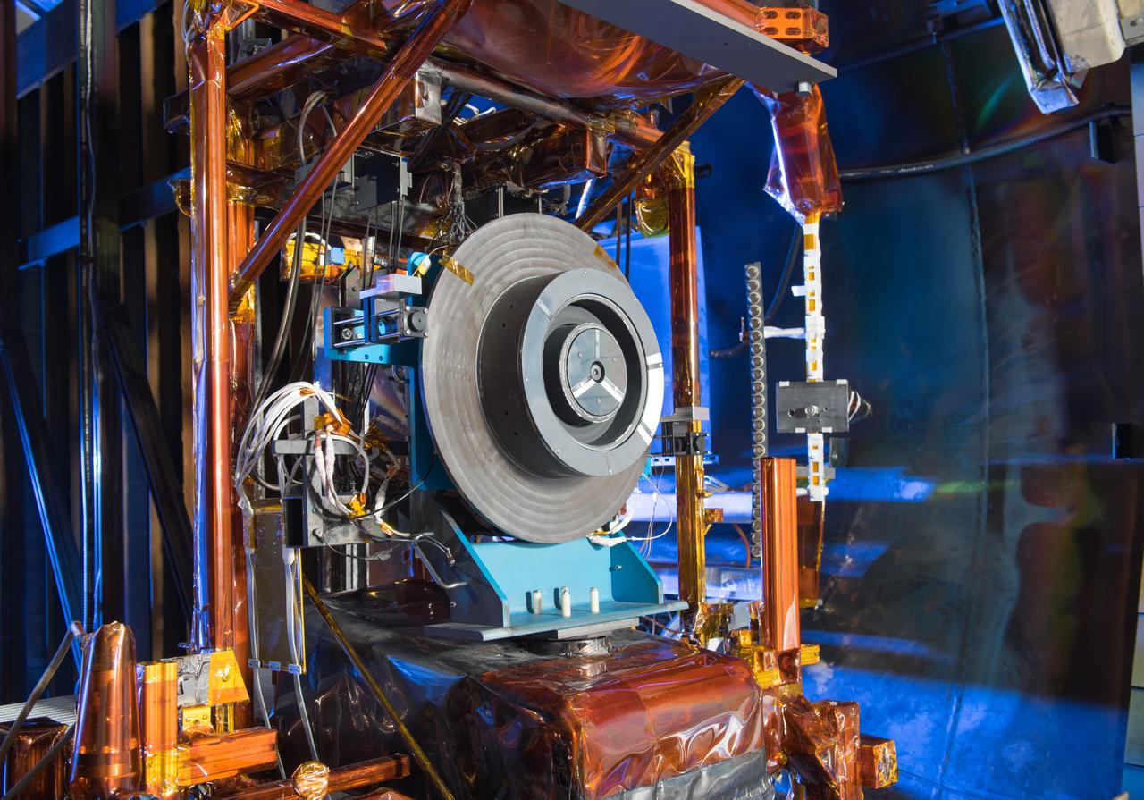
Advanced Electric Propulsion Systems Contract, Technology Demonstration Unit, TDU-3 Checkout Test Hardware Installed in Vacuum Facility 5, VF-5
Advanced Electric Propulsion Systems Contract, Technology Demonstration Unit, TDU-3 Checkout Test Hardware Installed in Vacuum Facility 5, VF-5
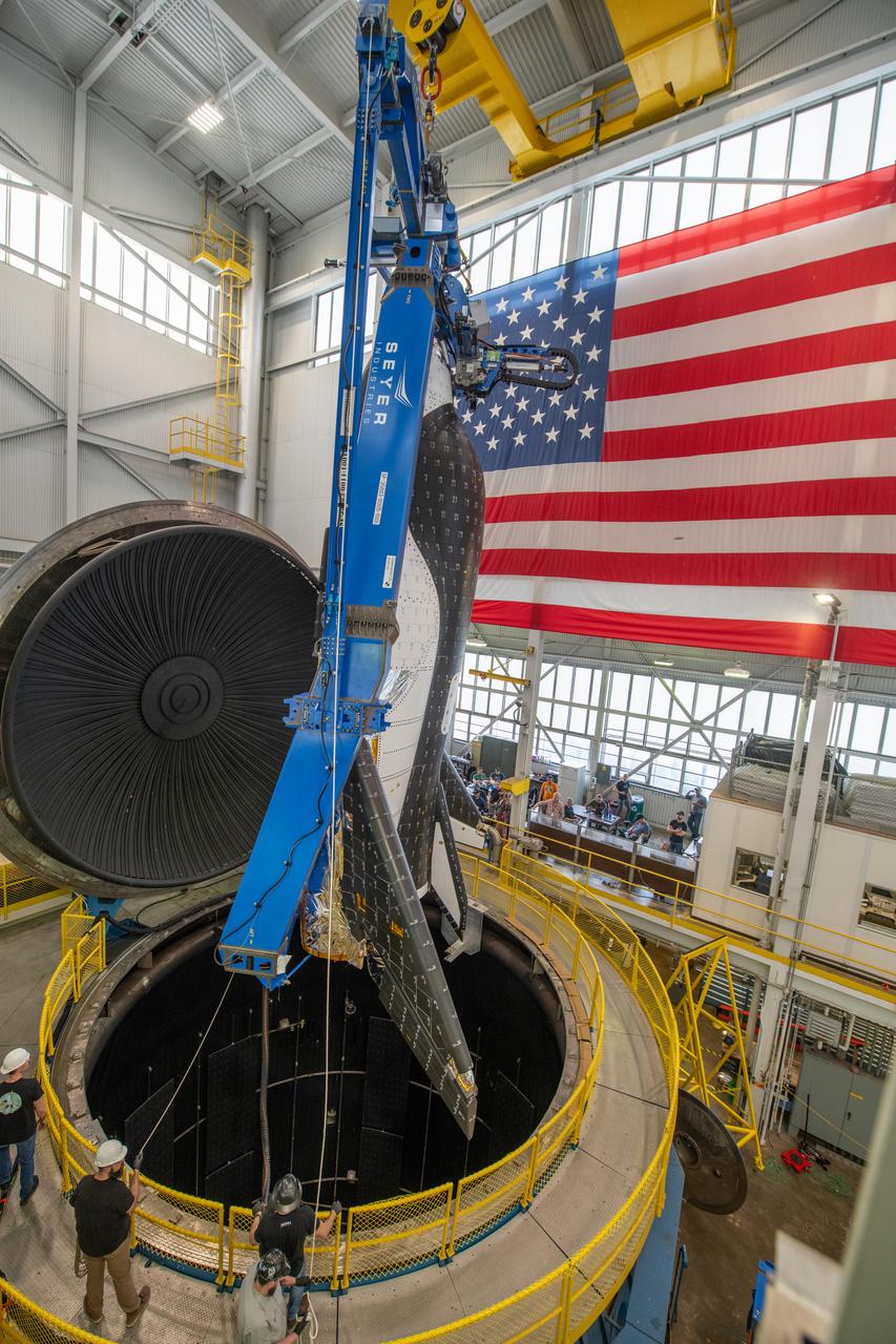
Sierra Space Dream Chaser space plane is lifted into the chamber at ISP (In Space Propulsion) facility, building 3211 at ATF (Armstrong Test Facility) for environmental testing. Once lowered into the test chamber, it will be exposed to the harsh cold conditions of space for extended periods of time.
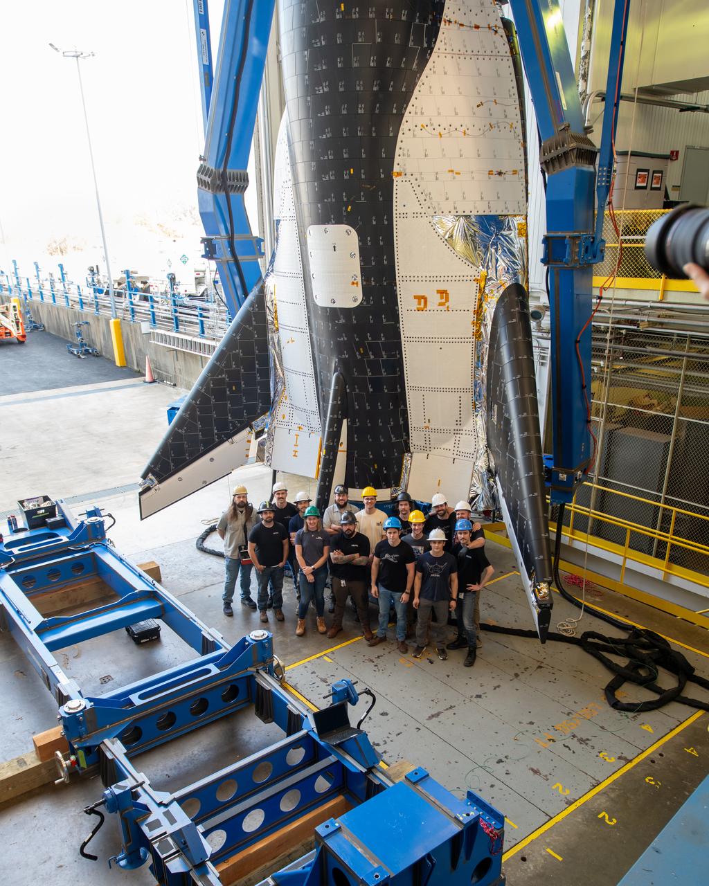
Group photo of the crew just before the critical lift of Dream Chaser into the chamber at ISP (In Space Propulsion) NASA GRC-ATF. Once lifted and lowered into the test chamber, it will be exposed to the harsh cold conditions of space for extended periods of time. Sierra Space Dream Chaser space plane will be lifted into the chamber at ISP (In Space Propulsion) facility, building 3211 at ATF (Armstrong Test Facility) for environmental testing
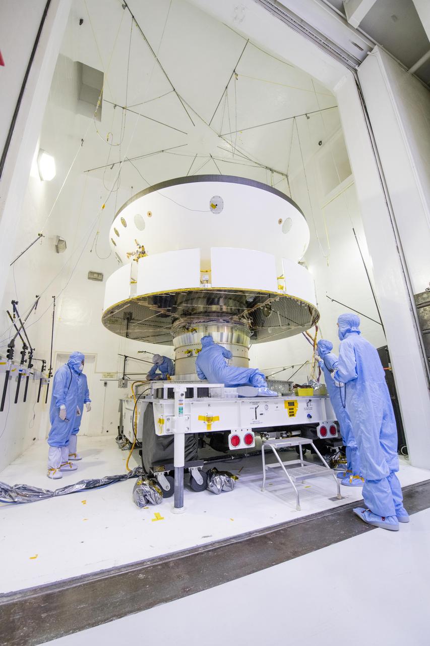
NASA's Mars 2020 spacecraft undergoes examination prior to an acoustic test in the Environmental Test Facility at NASA's Jet Propulsion Laboratory in Pasadena, California. The image was taken on April 11, 2019, at JPL. https://photojournal.jpl.nasa.gov/catalog/PIA23264
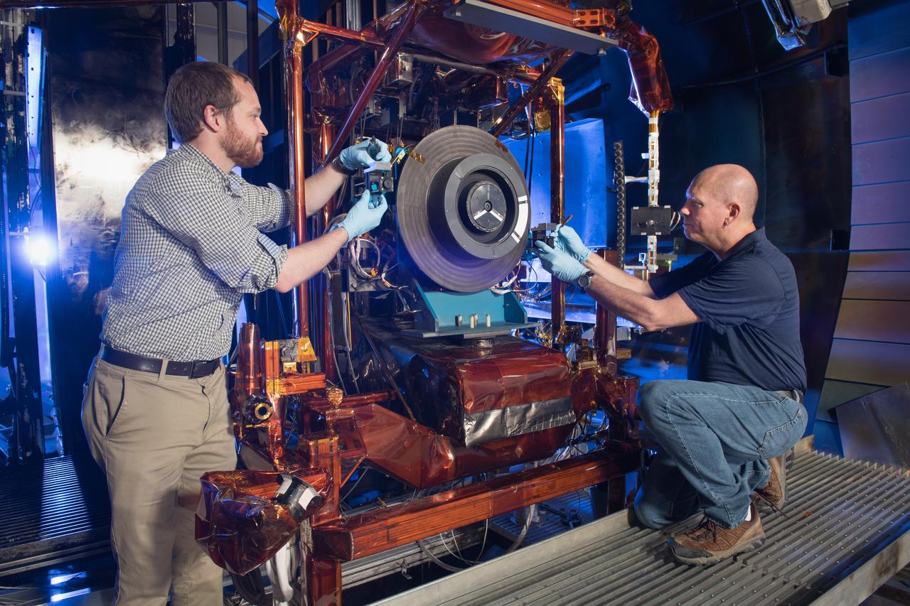
Advanced Electric Propulsion Systems Contract, Technology Demonstration Unit, TDU-3 Checkout Test Hardware Installed in Vacuum Facility 5, VF-5
Advanced Electric Propulsion Systems Contract, Technology Demonstration Unit, TDU-3 Checkout Test Hardware Installed in Vacuum Facility 5, VF-5
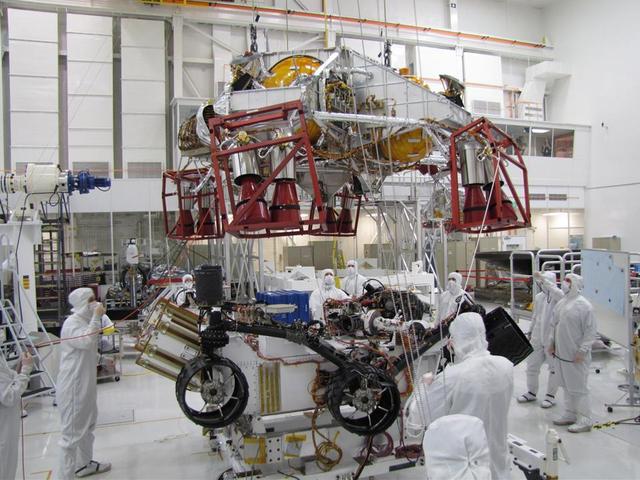
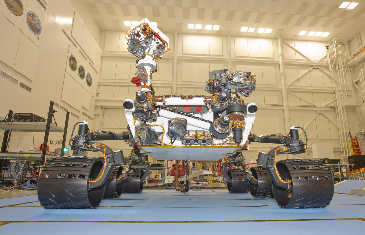
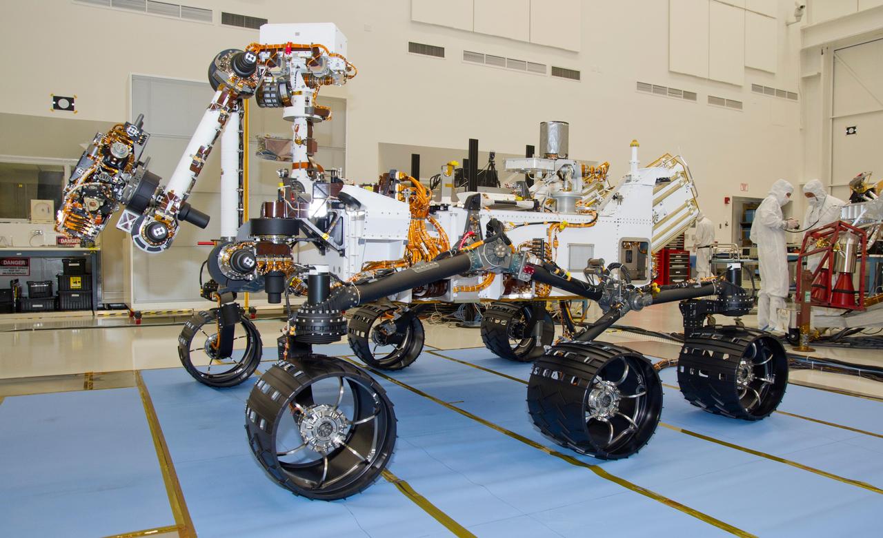
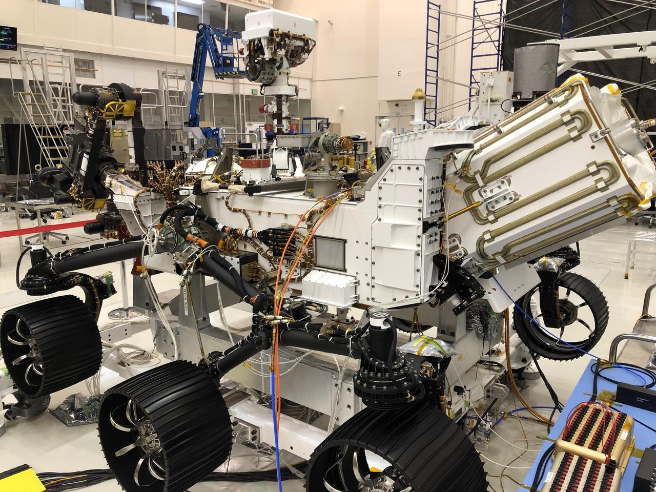
Spacecraft specialists test the descent stage and rover of the Mars Science Laboratory in this scene from the Spacecraft Assembly Facility at NASA Jet Propulsion Laboratory, Pasadena, Calif.
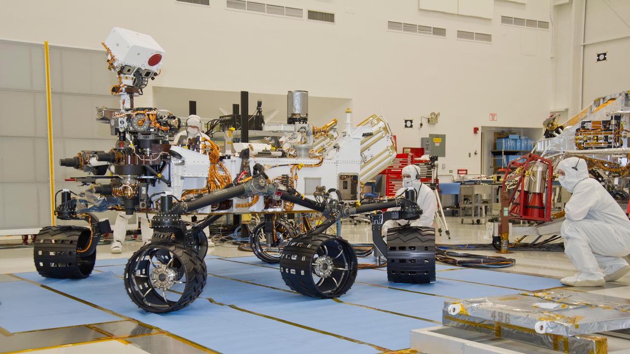
Test operators monitor how NASA Mars rover Curiosity handles driving over a ramp during a test on Sept. 10, 2010, inside the Spacecraft Assembly Facility at NASA Jet Propulsion Laboratory, Pasadena, Calif.
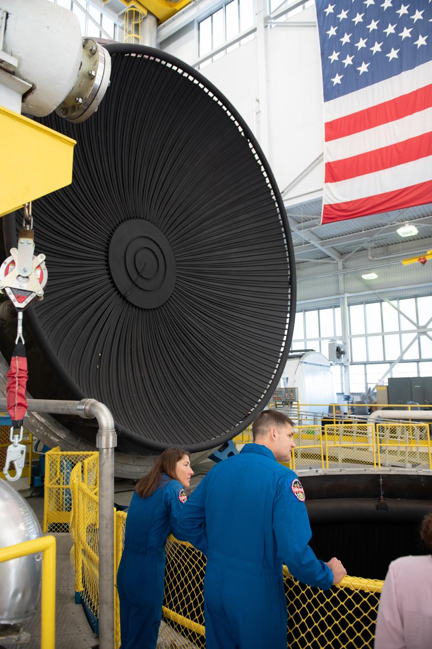
Tours were given of the In Space Propulsion Facility (ISP). NASA’s Facility is the world’s only high altitude test facility capable of full-scale rocket engine and launch vehicle system level tests. The facility supports mission profile thermal vacuum simulation and engine firing. Pictured are Mission Specialists Christina Koch and Jeremy Hansen. Employees meet three of the four astronauts who will venture around the Moon on Artemis II, the first crewed flight paving the way for future lunar surface missions. Commander Reid Wiseman and Mission Specialists Christina Koch and Jeremy Hansen will be on hand to discuss their upcoming mission and participate in a Question and Answer session with employees afterward. Hansen is an astronaut with the Canadian Space Agency. Victor Glover, the pilot and fourth crew member, was not present. Photo Credit: (NASA/Sara Lowthian-Hanna)
Engineers prepare the Mars 2020 spacecraft for a thermal vacuum (TVAC) test in the Space Simulator Facility at NASA's Jet Propulsion Laboratory in Pasadena, California. The image was taken on May 9, 2019. https://photojournal.jpl.nasa.gov/catalog/PIA23263
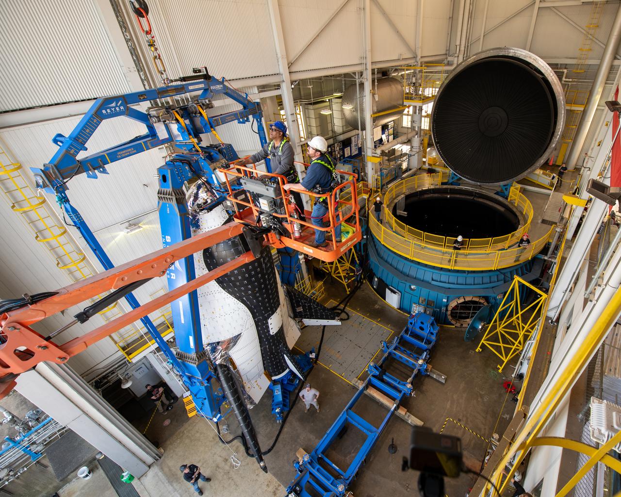
Final inspection of the crane operation just before the critical lift of the Sierra Space Plane, Dream Chaser. It will go into the chamber at ISP (In Space Propulsion) NASA GRC-ATF. Once lowered into the test chamber, it will be exposed to the harsh cold conditions of space for extended periods of time at building 3211 at ATF (Armstrong Test Facility) for environmental testing.
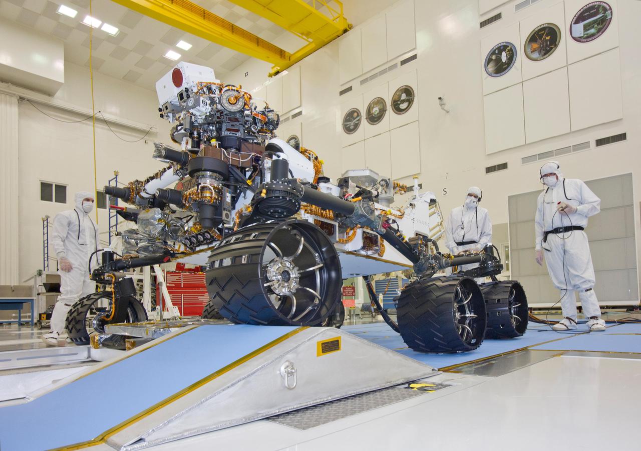
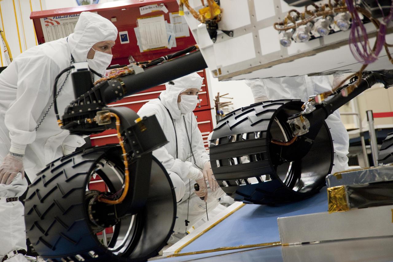
This photograph of the NASA Mars Science Laboratory rover, Curiosity, was taken during mobility testing on June 3, 2011. The location is inside the Spacecraft Assembly Facility at NASA Jet Propulsion Laboratory, Pasadena, Calif.
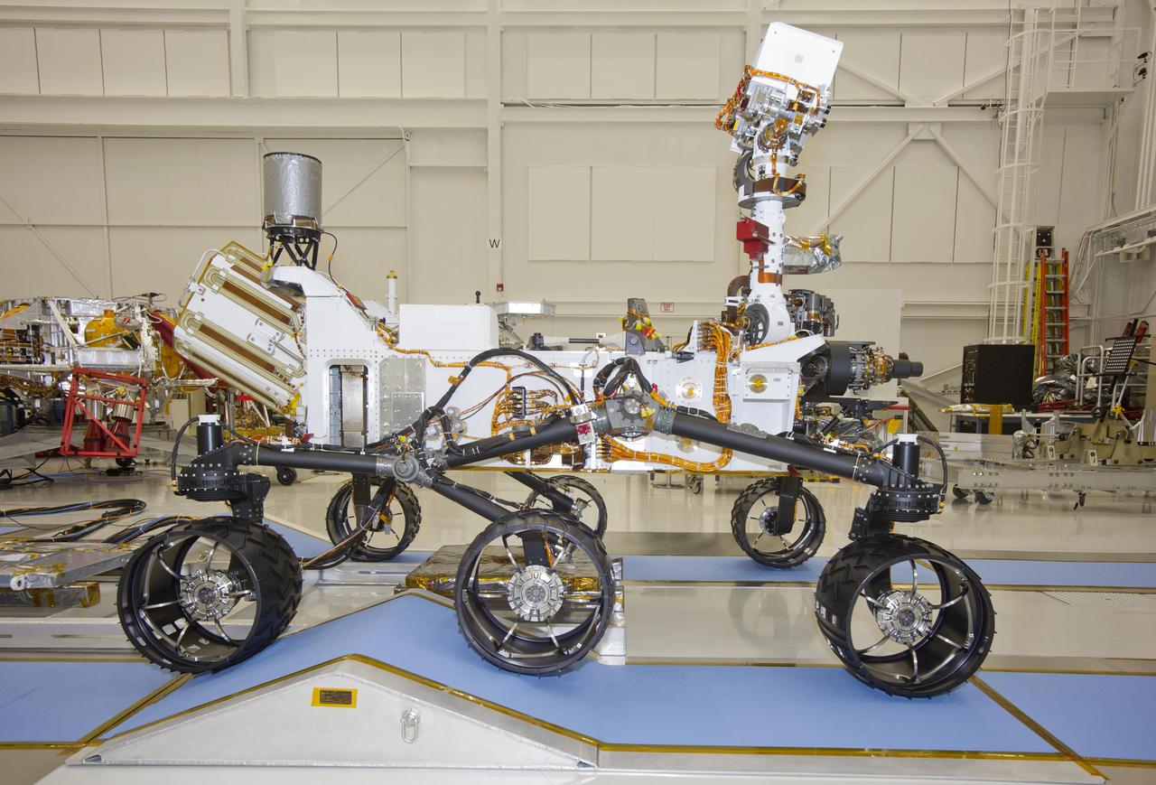
This photograph of the NASA Mars Science Laboratory rover, Curiosity, was taken during mobility testing on June 3, 2011. The location is inside the Spacecraft Assembly Facility at NASA Jet Propulsion Laboratory, Pasadena, Calif.
This photograph of the NASA Mars Science Laboratory rover, Curiosity, was taken during mobility testing on June 3, 2011. The location is inside the Spacecraft Assembly Facility at NASA Jet Propulsion Laboratory, Pasadena, Calif.
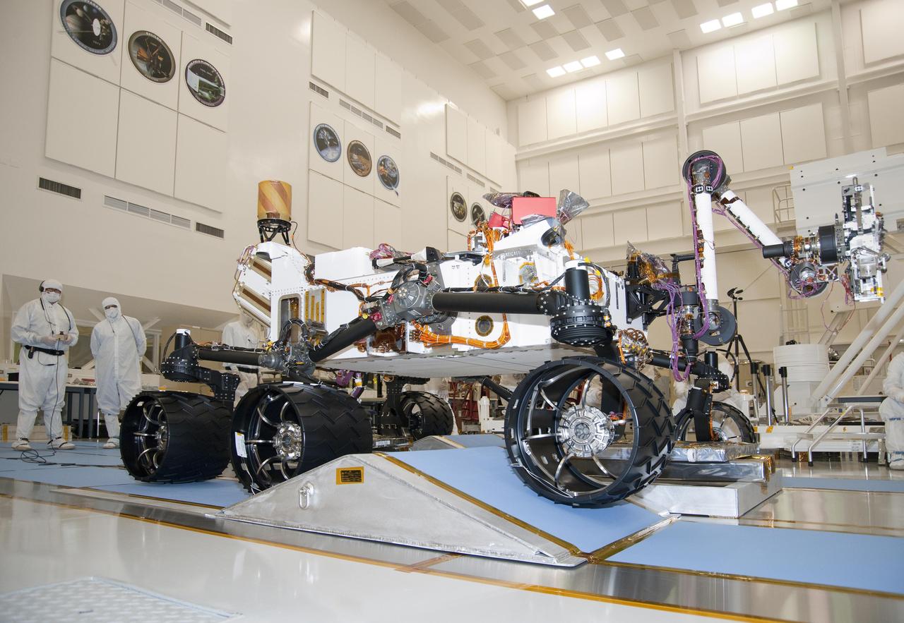
The suspension system on NASA Mars rover Curiosity easily accommodates rolling over a ramp in this Sept. 10, 2010, test drive inside the Spacecraft Assembly Facility at NASA Jet Propulsion Laboratory, Pasadena, Calif.
This photograph of the NASA Mars Science Laboratory rover, Curiosity, was taken during mobility testing on June 3, 2011. The location is inside the Spacecraft Assembly Facility at NASA Jet Propulsion Laboratory, Pasadena, Calif.
This photograph of the NASA Mars Science Laboratory rover, Curiosity, was taken during mobility testing on June 3, 2011. The location is inside the Spacecraft Assembly Facility at NASA Jet Propulsion Laboratory, Pasadena, Calif.
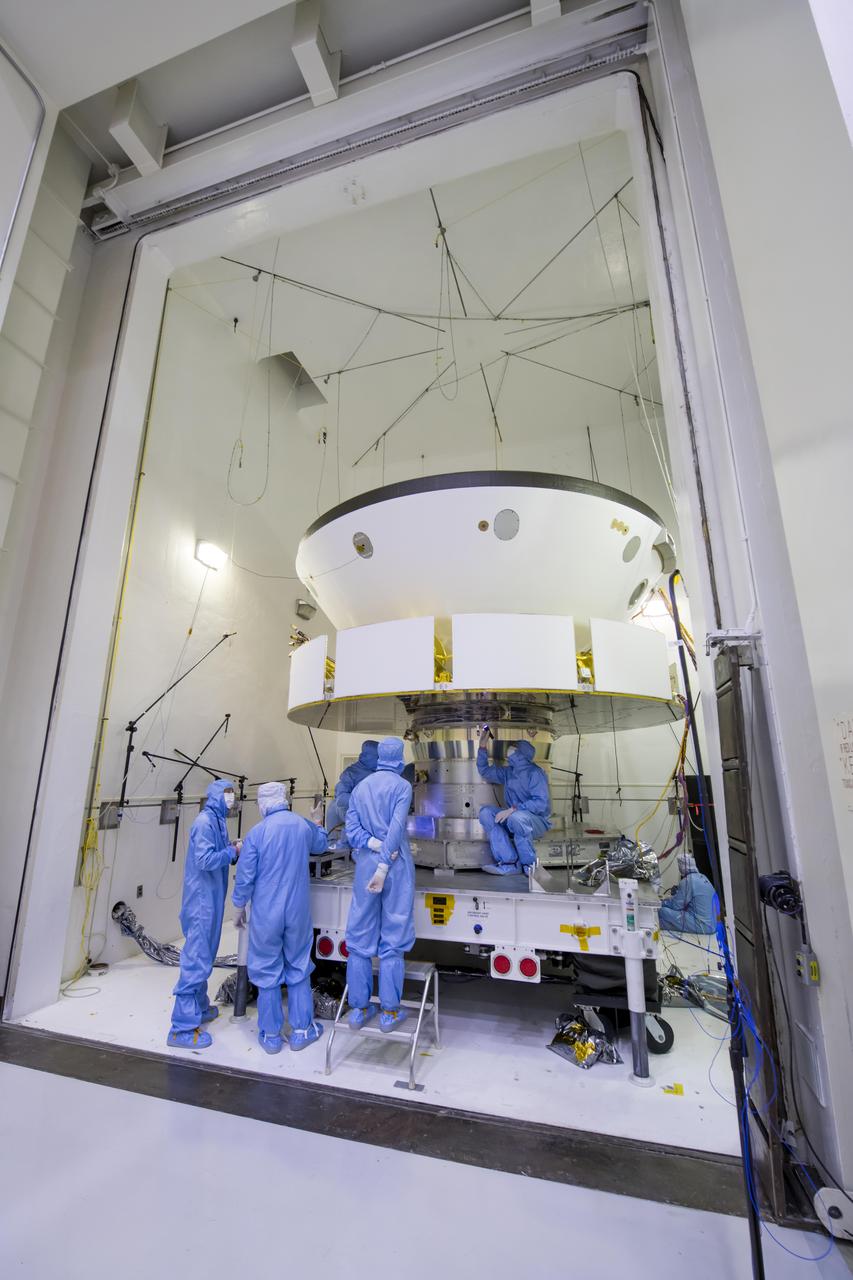
Engineers and technicians working on NASA's Mars 2020 mission prepare spacecraft components for acoustic testing in the Environmental Test Facility at NASA's Jet Propulsion Laboratory in Pasadena, California. The spacecraft is being tested in the same configuration it will be in when sitting atop the Atlas rocket that will launch the latest rover towards Mars in July 2020. The image was taken on April 11, 2019, at JPL. https://photojournal.jpl.nasa.gov/catalog/PIA23160
Technicians working Mars 2020's System's Test 1 approach their workstation in the Spacecraft Assembly Facility at NASA's Jet Propulsion Laboratory in Pasadena, Calif. Over two weeks in January 2019, 72 engineers and technicians assigned to the 2020 mission took over the High Bay 1 cleanroom in JPL's Spacecraft Assembly Facility to put the software and electrical systems aboard the mission's cruise, entry capsule, descent stage and rover through their paces. https://photojournal.jpl.nasa.gov/catalog/PIA23097
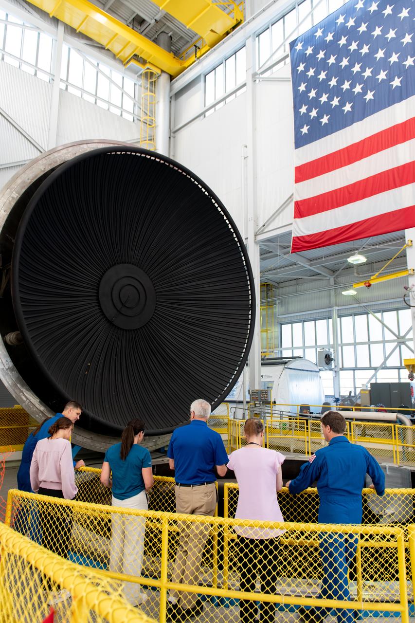
Tours were given of the In Space Propulsion Facility (ISP). NASA’s Facility is the world’s only high altitude test facility capable of full-scale rocket engine and launch vehicle system level tests. The facility supports mission profile thermal vacuum simulation and engine firing. Pictured are Mission Specialists Christina Koch and Jeremy Hansen, Penelope Garcia-Galan, Kathryn Oriti, General David Stringer, Tiffany O'Rourke and Commander Reid Wiseman. Employees meet three of the four astronauts who will venture around the Moon on Artemis II, the first crewed flight paving the way for future lunar surface missions. Commander Reid Wiseman and Mission Specialists Christina Koch and Jeremy Hansen will be on hand to discuss their upcoming mission and participate in a Question and Answer session with employees afterward. Hansen is an astronaut with the Canadian Space Agency. Victor Glover, the pilot and fourth crew member, will not be present.
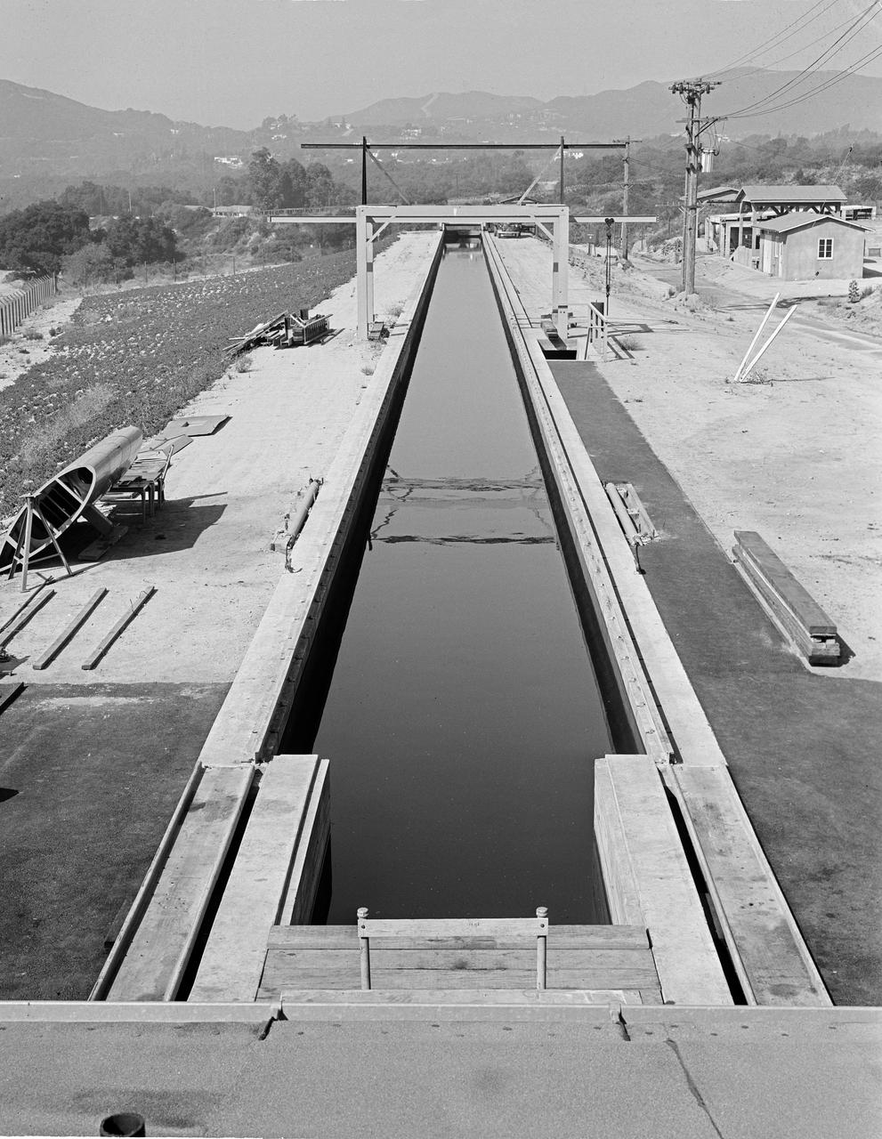
This archival image was released as part of a gallery comparing JPL's past and present, commemorating the 80th anniversary of NASA's Jet Propulsion Laboratory on Oct. 31, 2016. During World War II, the Jet Propulsion Laboratory had a contract with the U.S. Army to develop rocket torpedoes. This picture from August 1944 shows the test facility, known as the "Tow Channel." It was used for storage for many years before being torn out to make space for the Earth and Space Science Laboratory (Building 300) and the Microdevices Laboratory (Building 302). http://photojournal.jpl.nasa.gov/catalog/PIA21124
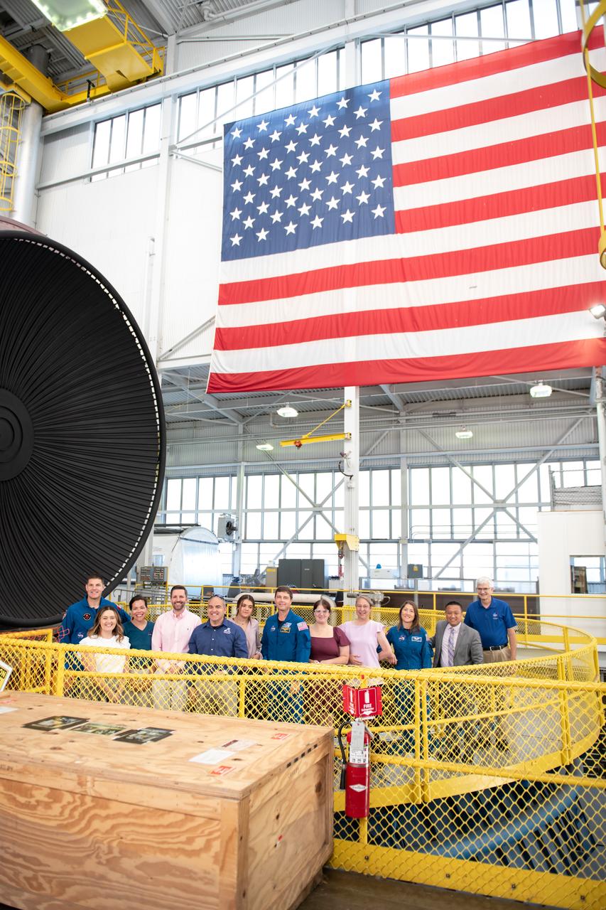
Tours were given of the In Space Propulsion Facility (ISP) in Sandusky, OH at Neil Armstrong Test Facility. NASA’s Facility is the world’s only high altitude test facility capable of full-scale rocket engine and launch vehicle system level tests. The facility supports mission profile thermal vacuum simulation and engine firing. From Left to Right: Jeremy Hansen, Allison Tankersley, Kathryn Oriti, Jan-Henrik Horstmann, Carlos Garcia-Galan, Penelope Garcia-Galan, Reid Wiseman, Jessica Isabell, Tiffany O'Rourke, Howard Hu, General David Stringer. Commander Reid Wiseman and Mission Specialists Christina Koch and Jeremy Hansen will be on hand to discuss their upcoming mission and participate in a Question and Answer session with employees afterward. Hansen is an astronaut with the Canadian Space Agency. Victor Glover, the pilot and fourth crew member, will not be present. Photo Credit: (NASA/Sara Lowthian-Hanna)
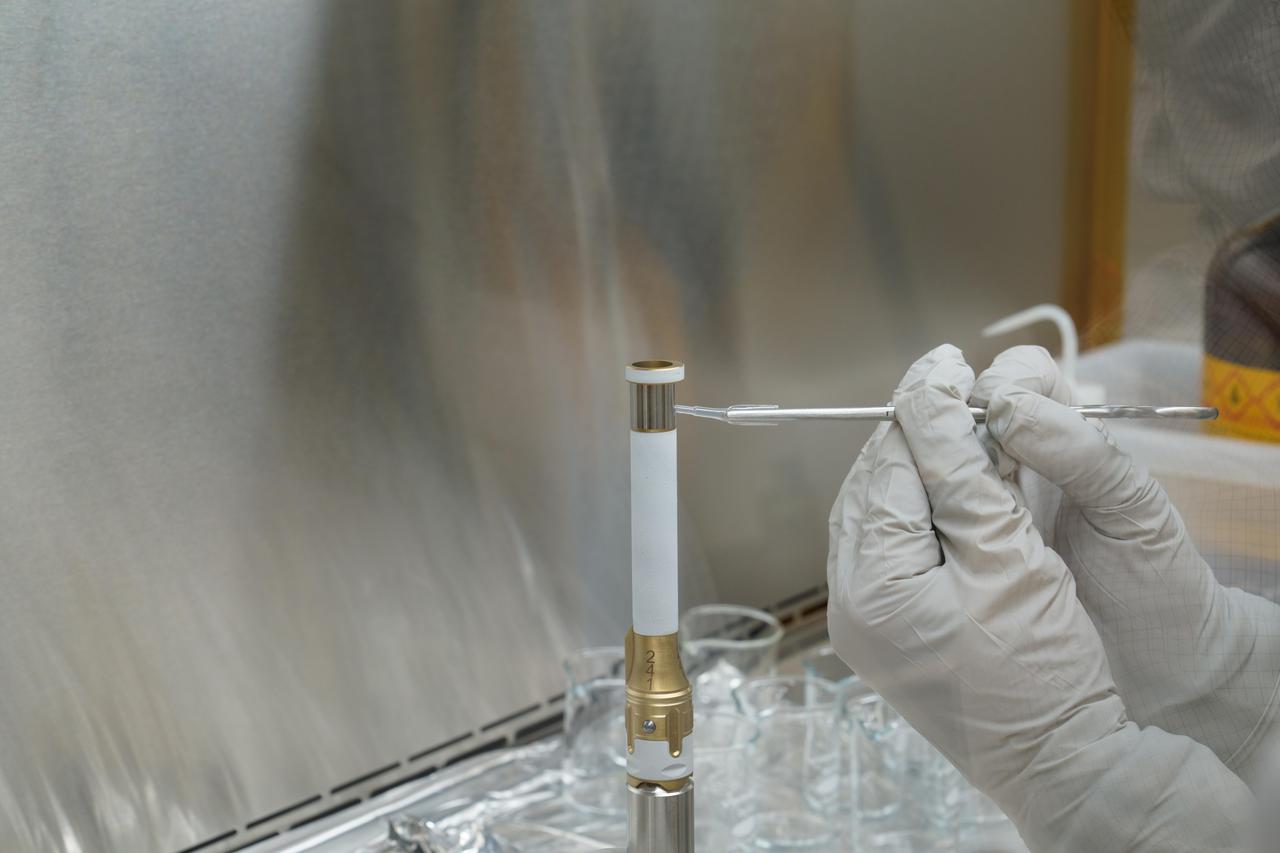
A technician working on the Mars 2020 Perseverance rover mission takes a sample from the surface of sample tube 241 to test for contamination. Each sample tube has its own unique serial number (seen on the gold-colored portion of the tube). The image was taken in a clean room facility at NASA's Jet Propulsion Laboratory in Southern California, where the tubes were developed and assembled. https://photojournal.jpl.nasa.gov/catalog/PIA24294
A 48 inch Advanced Solid Rocket Motor is test fired at Marshall's Solid Propulsion Research Test Article facility for M-NASA Project.
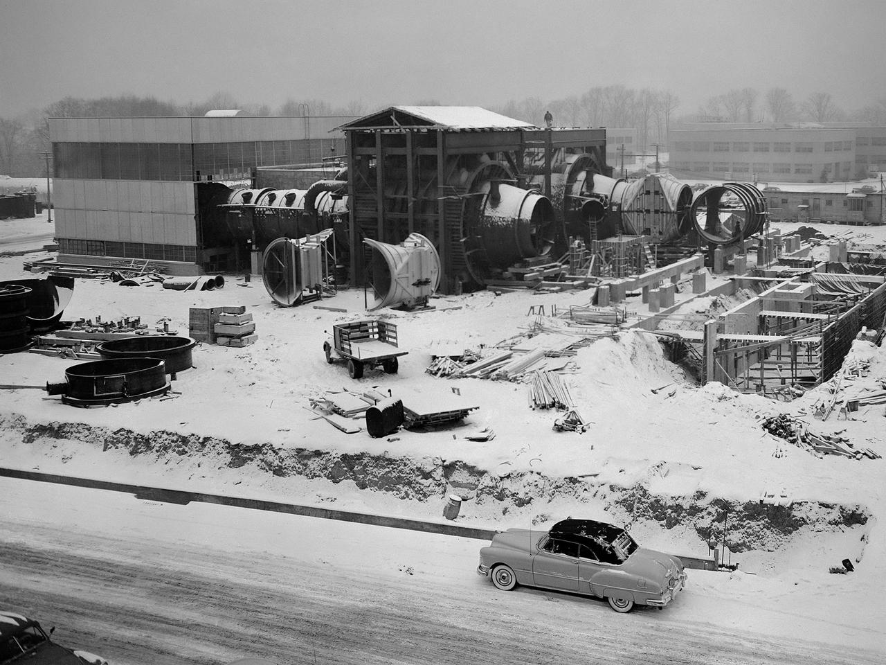
Construction of the Propulsion Systems Laboratory No. 1 and 2 at the National Advisory Committee for Aeronautics (NACA) Lewis Flight Propulsion Laboratory. When it began operation in late 1952, the Propulsion Systems Laboratory was the NACA’s most powerful facility for testing full-scale engines at simulated flight altitudes. The facility contained two altitude simulating test chambers which were a technological combination of the static sea-level test stands and the complex Altitude Wind Tunnel, which recreated actual flight conditions on a larger scale. NACA Lewis began designing the new facility in 1947 as part of a comprehensive plan to improve the altitude testing capabilities across the lab. The exhaust, refrigeration, and combustion air systems from all the major test facilities were linked. In this way, different facilities could be used to complement the capabilities of one another. Propulsion Systems Laboratory construction began in late summer 1949 with the installation of an overhead exhaust pipe connecting the facility to the Altitude Wind Tunnel and Engine Research Building. The large test section pieces arriving in early 1951, when this photograph was taken. The two primary coolers for the altitude exhaust are in place within the framework near the center of the photograph.
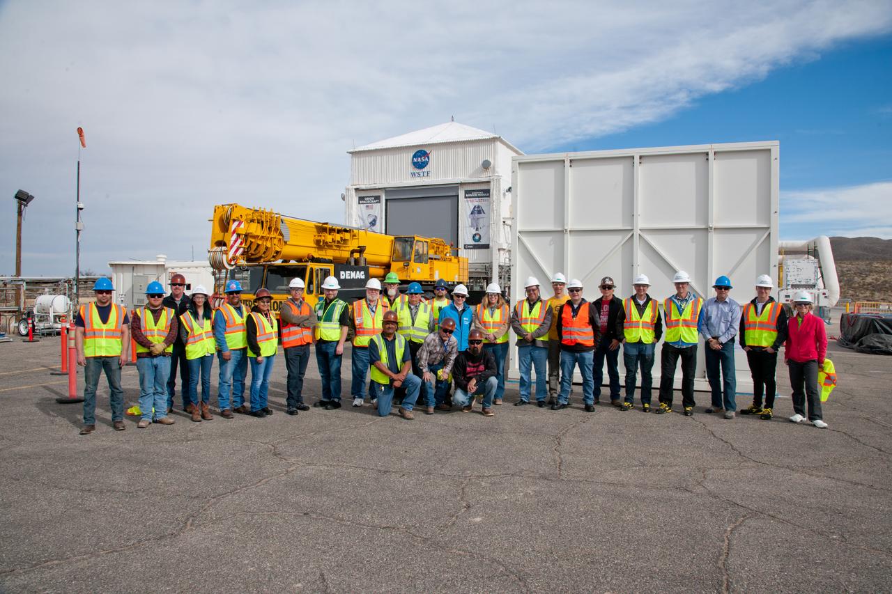
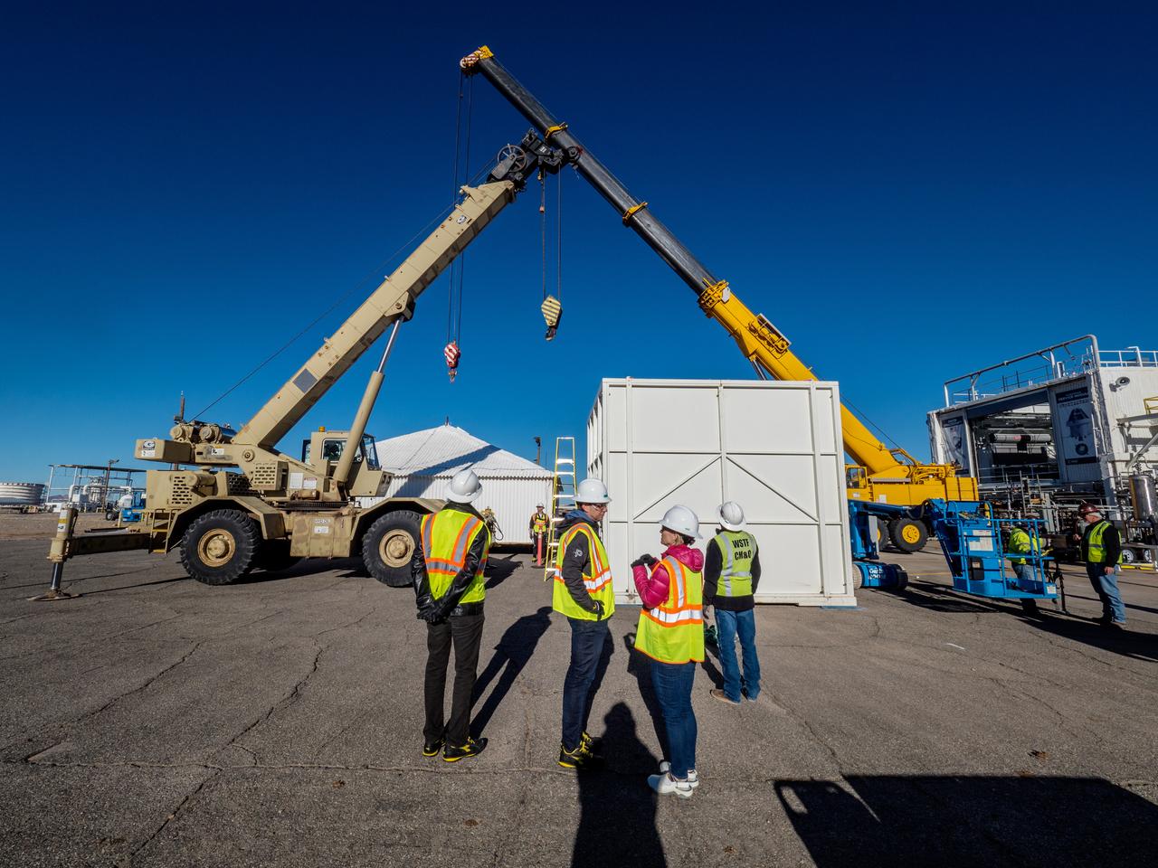
The European Service Module Propulsion Qualification Module (PQM) arrives at White Sands Test Facility in New Mexico on Feb. 18, 2017.

The European Service Module Propulsion Qualification Module (PQM) arrives at White Sands Test Facility in New Mexico on Feb. 18, 2017.
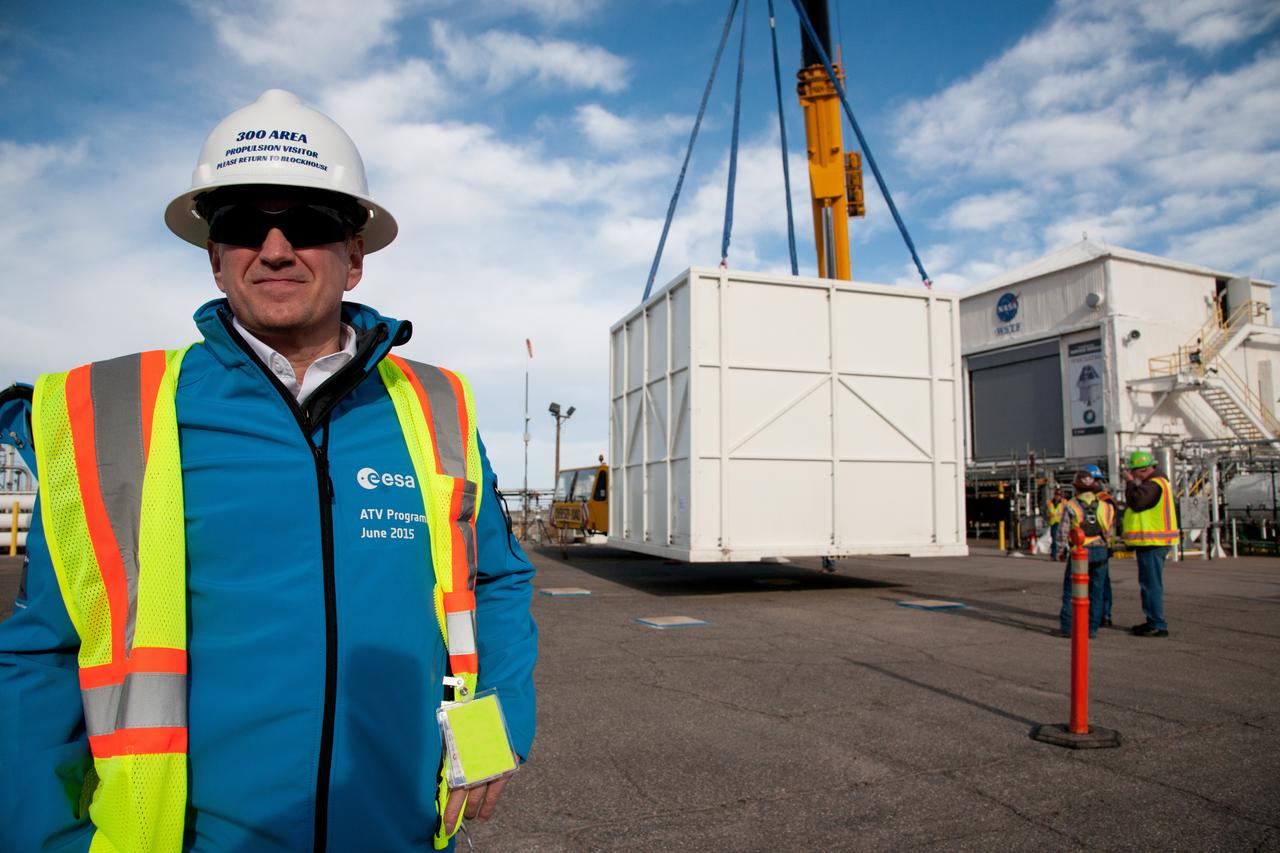
The European Service Module Propulsion Qualification Module (PQM) arrives at White Sands Test Facility in New Mexico on Feb. 18, 2017.
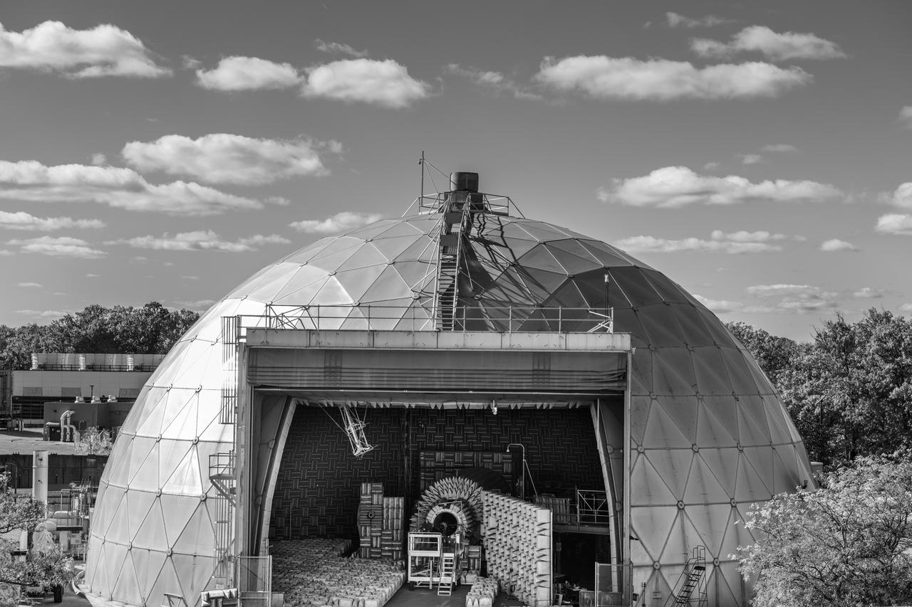
The Aero-Acoustic Propulsion Laboratory (AAPL) photographed on October 24, 2024 as seen from above. This facility provides world class testing for aircraft propulsion acoustic noise reduction and is 65 ft high by 130 ft in diameter. Photo Credit: (NASA/Sara Lowthian-Hanna)
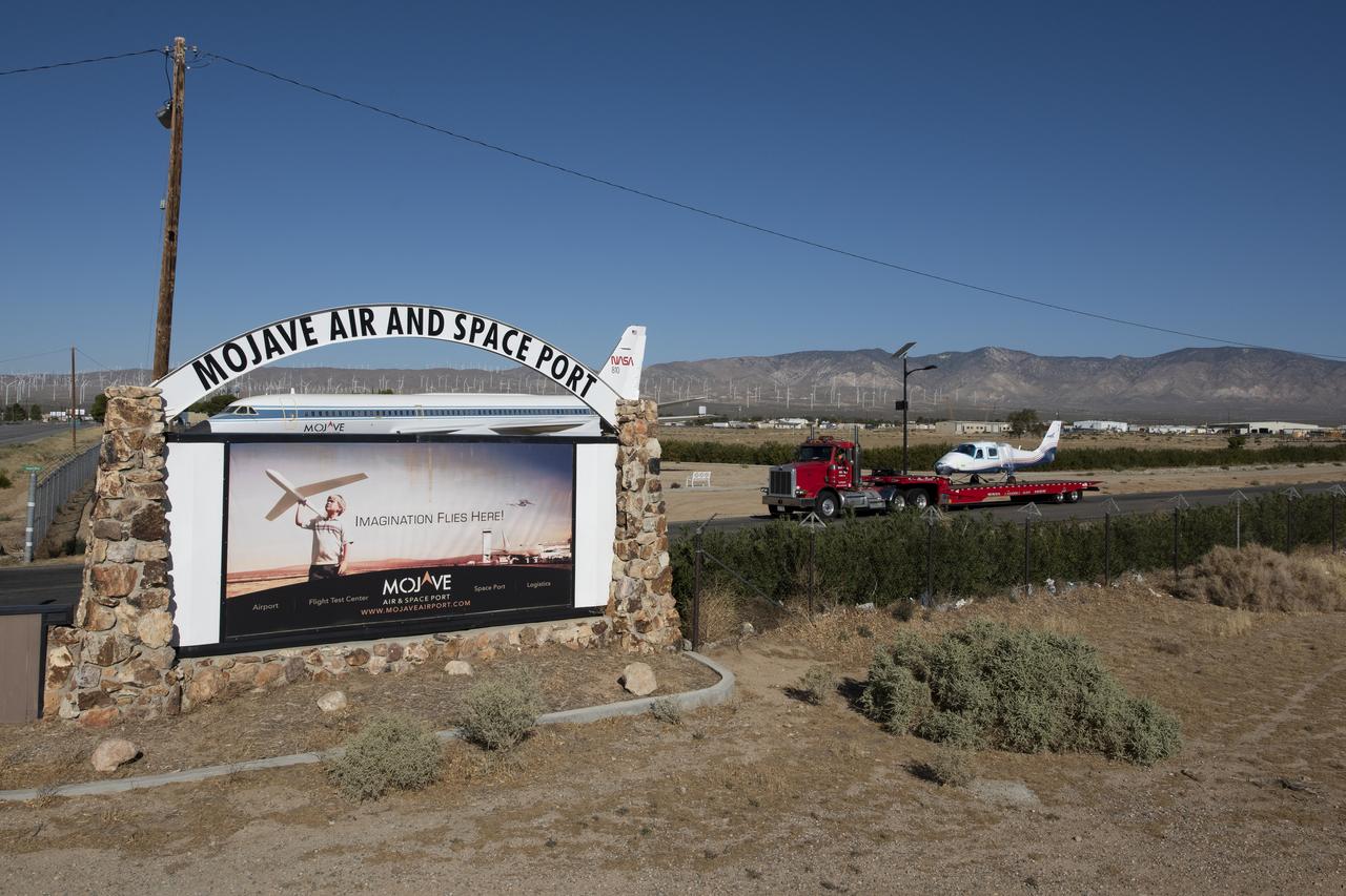
NASA’s all-electric X-57 Maxwell, in its Mod II configuration, departs Scaled Composites’ facility at Mojave Air and Space Port, en route to NASA’s Armstrong Flight Research Center in Edwards, California for delivery. The aircraft, shipped as two parts – the fuselage and the wing – was delivered to NASA Armstrong’s Research Aircraft Integration Facility, where it will be reintegrated to begin ground tests, to be followed by taxi tests, and eventually, flight tests. X-57’s Mod II configuration, the first of three primary modifications for the project, involves testing of the aircraft’s cruise electric propulsion system. The goal of the X-57 project is to share the aircraft’s electric-propulsion-focused design and airworthiness process with regulators, to advance certification approaches for distributed electric propulsion in general aviation.
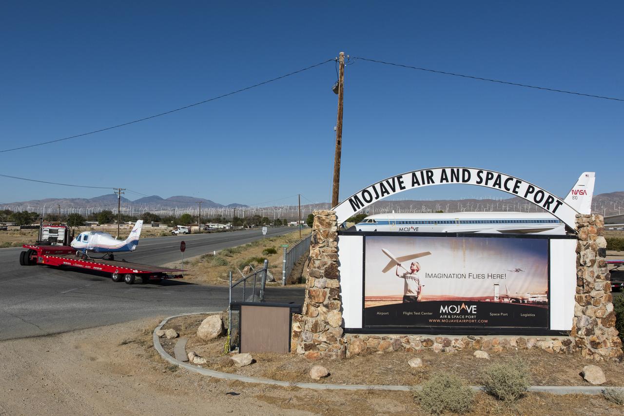
NASA’s all-electric X-57 Maxwell, in its Mod II configuration, departs Scaled Composites’ facility at Mojave Air and Space Port, en route to NASA’s Armstrong Flight Research Center in Edwards, California for delivery. The aircraft, shipped as two parts – the fuselage and the wing – was delivered to NASA Armstrong’s Research Aircraft Integration Facility, where it will be reintegrated to begin ground tests, to be followed by taxi tests, and eventually, flight tests. X-57’s Mod II configuration, the first of three primary modifications for the project, involves testing of the aircraft’s cruise electric propulsion system. The goal of the X-57 project is to share the aircraft’s electric-propulsion-focused design and airworthiness process with regulators, to advance certification approaches for distributed electric propulsion in general aviation.

NASA's all-electric X-57 Maxwell, in its Mod II configuration, departs Scaled Composites' facility at Mojave Air and Space Port, en route to NASA's Armstrong Flight Research Center in Edwards, California for delivery. The aircraft, shipped as two parts - the fuselage and the wing - was delivered to NASA Armstrong's Research Aircraft Integration Facility, where it will be reintegrated to begin ground tests, to be followed by taxi tests, and eventually, flight tests. X-57's Mod II configuration, the first of three primary modifications for the project, involves testing of the aircraft's cruise electric propulsion system. The goal of the X-57 project is to share the aircraft's electric-propulsion-focused design and airworthiness process with regulators, to advance certification approaches for distributed electric propulsion in general aviation.
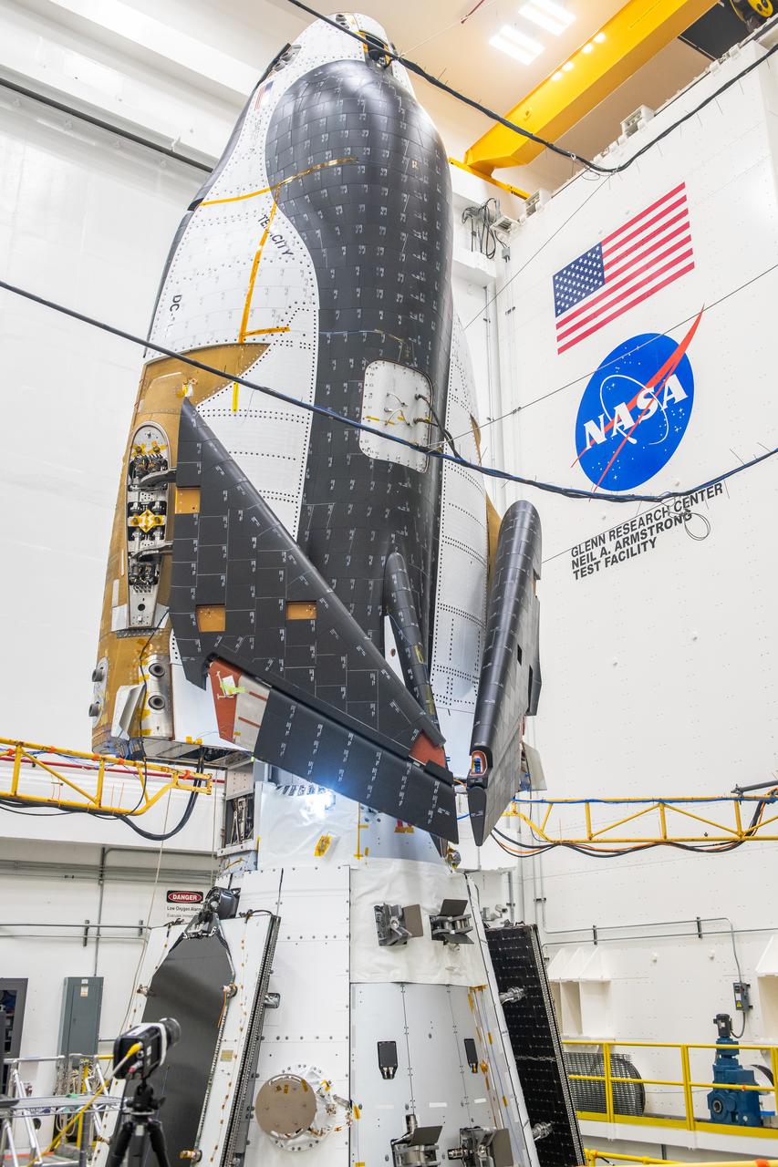
The Neil Armstrong Test Facility, part of NASA’s Glenn Research Center in Cleveland, is home to multiple test facilities, including the Space Environments Complex and the In-Space Propulsion Facility, both stops for Dream Chaser. The complex is home to the Mechanical Vibration Facility, which subjects test articles to the rigorous conditions of launch. While at Armstrong, the Dream Chaser winged spacecraft was stacked atop its Shooting Star cargo module on the vibration table to experience vibrations like those during launch and re-entry to the Earth’s atmosphere.
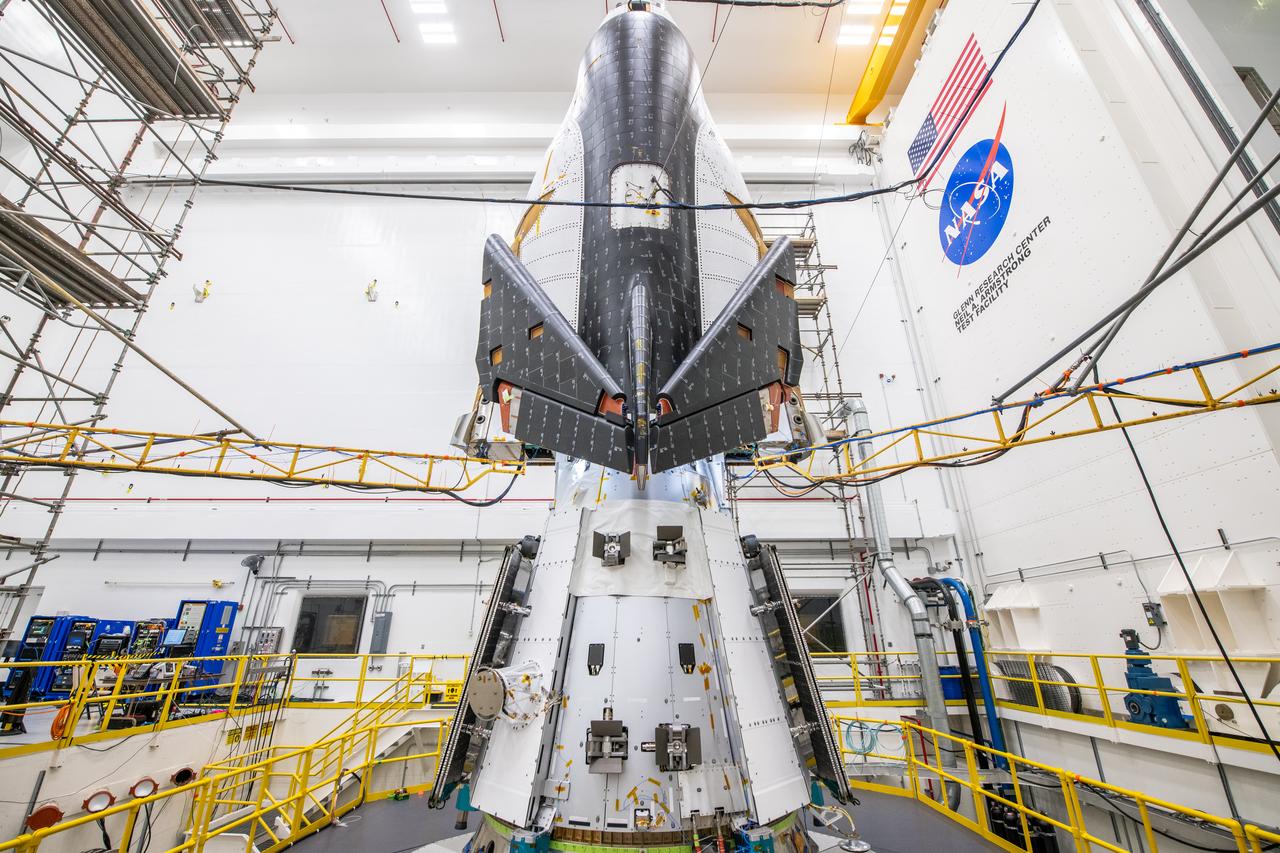
The Neil Armstrong Test Facility, part of NASA’s Glenn Research Center in Cleveland, is home to multiple test facilities, including the Space Environments Complex and the In-Space Propulsion Facility, both stops for Dream Chaser. The complex is home to the Mechanical Vibration Facility, which subjects test articles to the rigorous conditions of launch. While at Armstrong, the Dream Chaser winged spacecraft was stacked atop its Shooting Star cargo module on the vibration table to experience vibrations like those during launch and re-entry to the Earth’s atmosphere.
The Neil Armstrong Test Facility, part of NASA’s Glenn Research Center in Cleveland, is home to multiple test facilities, including the Space Environments Complex and the In-Space Propulsion Facility, both stops for Dream Chaser. The complex is home to the Mechanical Vibration Facility, which subjects test articles to the rigorous conditions of launch. While at Armstrong, the Dream Chaser winged spacecraft was stacked atop its Shooting Star cargo module on the vibration table to experience vibrations like those during launch and re-entry to the Earth’s atmosphere.

One of the two primary coolers at the Propulsion Systems Laboratory at the National Advisory Committee for Aeronautics (NACA) Lewis Flight Propulsion Laboratory. Engines could be run in simulated altitude conditions inside the facility’s two 14-foot-diameter and 24-foot-long test chambers. The Propulsion Systems Laboratory was the nation’s only facility that could run large full-size engine systems in controlled altitude conditions. At the time of this photograph, construction of the facility had recently been completed. Although not a wind tunnel, the Propulsion Systems Laboratory generated high-speed airflow through the interior of the engine. The air flow was pushed through the system by large compressors, adjusted by heating or refrigerating equipment, and de-moisturized by air dryers. The exhaust system served two roles: reducing the density of the air in the test chambers to simulate high altitudes and removing hot gases exhausted by the engines being tested. It was necessary to reduce the temperature of the extremely hot engine exhaust before the air reached the exhauster equipment. As the air flow exited through exhaust section of the test chamber, it entered into the giant primary cooler seen in this photograph. Narrow fins or vanes inside the cooler were filled with water. As the air flow passed between the vanes, its heat was transferred to the cooling water. The cooling water was cycled out of the system, carrying with it much of the exhaust heat.
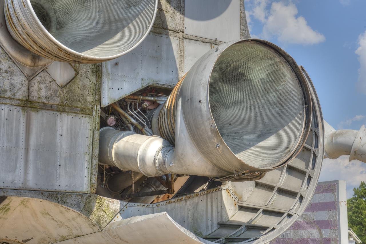
CLOSE-UP OF H-1 ENGINE INSTALLED ON SATURN S-1B STAGE (SA-T) NEAR PROPULSION AND STRUCTURAL TEST FACILITY (BUILDING 4572) AT THE GEORGE C. MARSHALL SPACE FLIGHT CENTER.
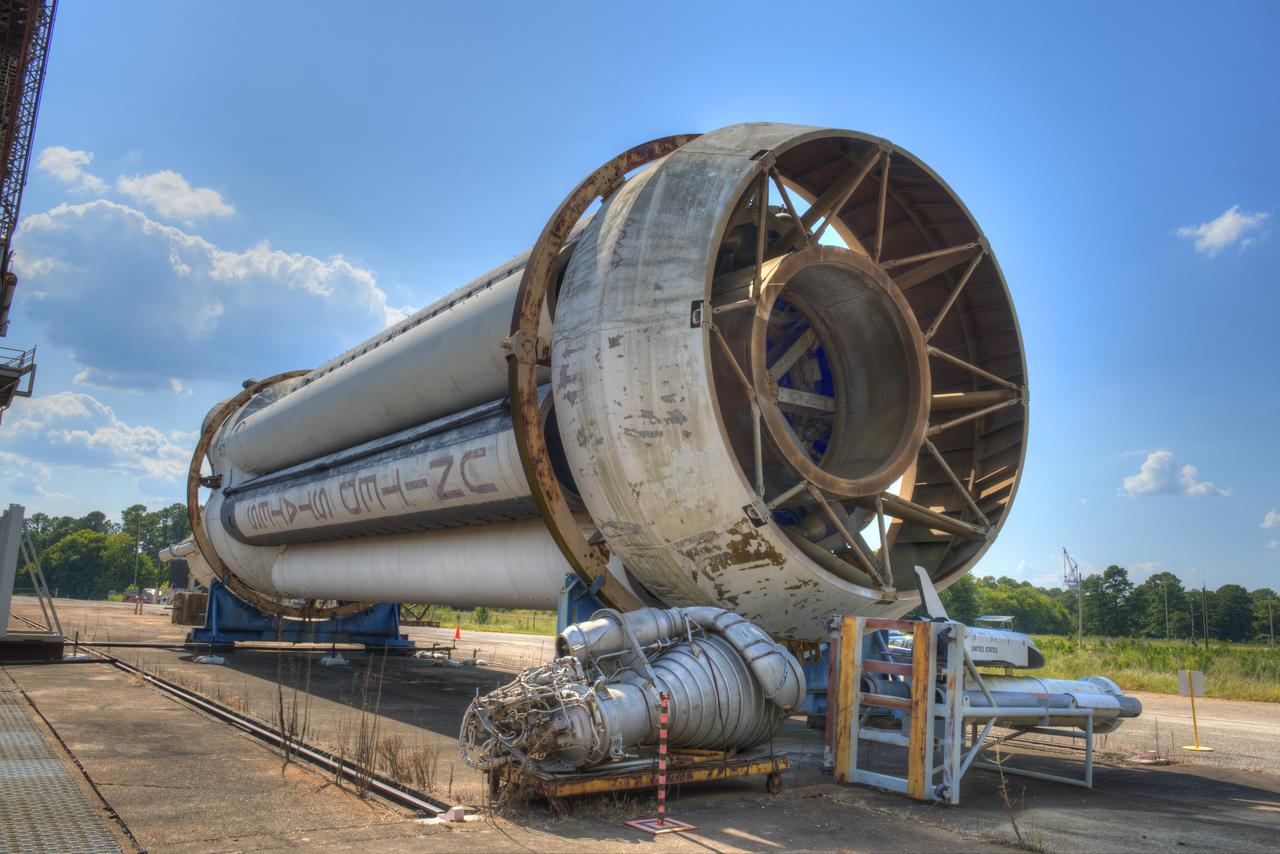
FORWARD END OF SATURN S-1B STAGE (SA-T) NEAR PROPULSION AND STRUCTURAL TEST FACILITY (BUILDING 4572) AT THE GEORGE C. MARSHALL SPACE FLIGHT CENTER IN HUNTSVILLE, ALABAMA
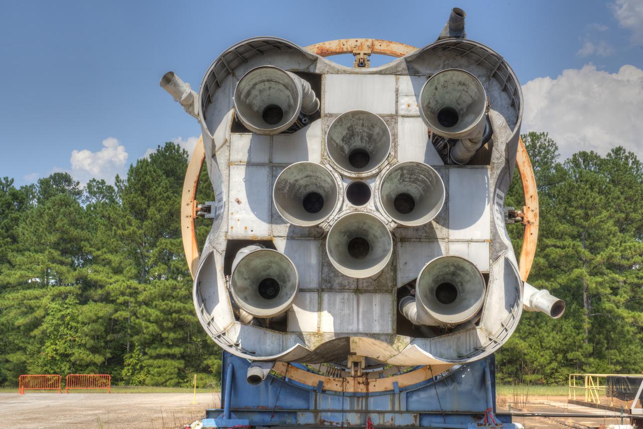
CLOSE-UP OF AFT END OF SATURN S-1B STAGE (SA-T) NEAR PROPULSION AND STRUCTURAL TEST FACILITY (BUILDING 4572) AT THE GEORGE C. MARSHALL SPACE FLIGHT CENTER IN HUNTSVILLE, ALABAMA.
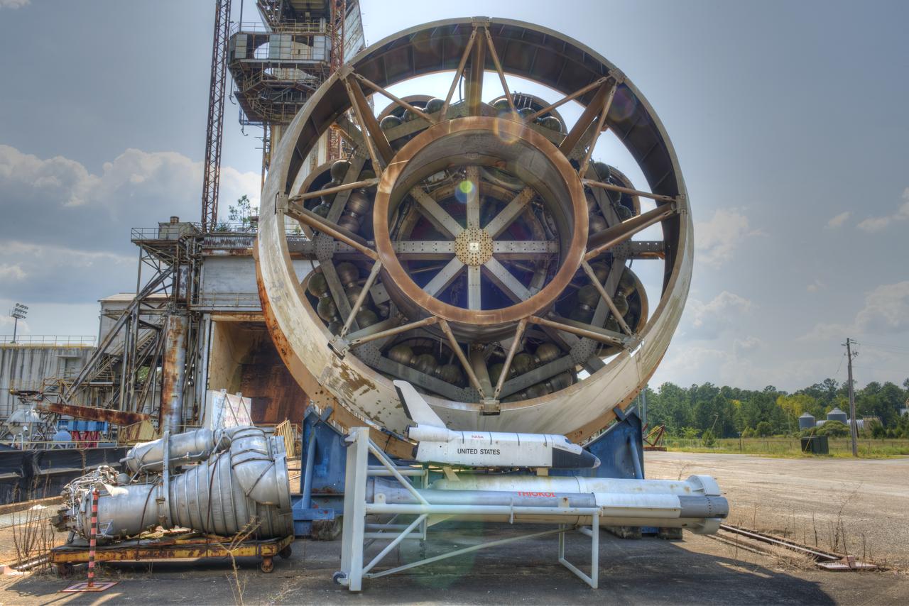
FORWARD END OF SATURN S-1B STAGE (SA-T) NEAR PROPULSION AND STRUCTURAL TEST FACILITY (BUILDING 4572) AT THE GEORGE C. MARSHALL SPACE FLIGHT CENTER IN HUNTSVILLE, ALABAMA
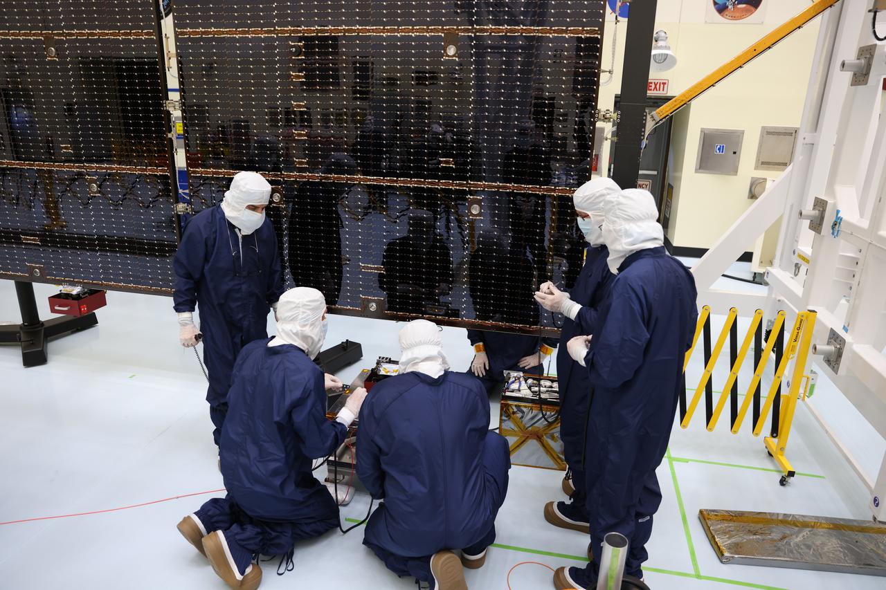
On March 20, technicians working inside the Payload Hazardous Servicing Facility at the agency’s Kennedy Space Center in Florida installed and began to test antennas on a solar array for NASA’s Europa Clipper spacecraft. The spacecraft will ship to Florida later this year from NASA’s Jet Propulsion Lab in Southern California in preparation for launch aboard a SpaceX Falcon Heavy rocket from Kennedy’s Launch Complex 39A. Europa Clipper is the largest spacecraft NASA has ever developed for a planetary mission, and it will seek to determine whether there are places below the surface of Jupiter’s icy moon, Europa, that could support life.
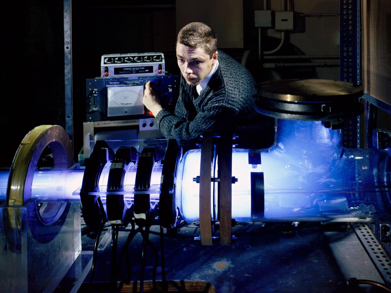
Raymond Palmer, of the Electromagnetic Propulsion Division’s Plasma Flow Section, adjusts the traveling magnetic wave plasma engine being operated in the Electric Power Conversion at the National Aeronautics and Space Administration (NASA) Lewis Research Center. During the 1960s Lewis researchers were exploring several different methods of creating electric propulsion systems, including the traveling magnetic wave plasma engine. The device operated similarly to alternating-current motors, except that a gas, not a solid, was used to conduct the electricity. A magnetic wave induced a current as it passed through the plasma. The current and magnetic field pushed the plasma in one direction. Palmer and colleague Robert Jones explored a variety of engine configurations in the Electric Propulsion Research Building. The engine is seen here mounted externally on the facility’s 5-foot diameter and 16-foot long vacuum tank. The four magnetic coils are seen on the left end of the engine. The researchers conducted two-minute test runs with varying configurations and used of both argon and xenon as the propellant. The Electric Propulsion Research Building was built in 1942 as the Engine Propeller Research Building, often called the Prop House. It contained four test cells to study large reciprocating engines with their propellers. After World War II, the facility was modified to study turbojet engines. By the 1960s, the facility was modified again for electric propulsion research and given its current name.
In this image taken on Nov. 16, 2019, the Perseverance rover is undergoing a 10-day test in the Spacecraft Assembly Facility's High Bay 1 at NASA's Jet Propulsion Laboratory in Southern California. During the test, all aspects of the upcoming mission were investigated (launch, cruise, landing and surface operations). https://photojournal.jpl.nasa.gov/catalog/PIA24044
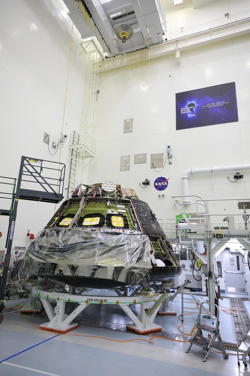
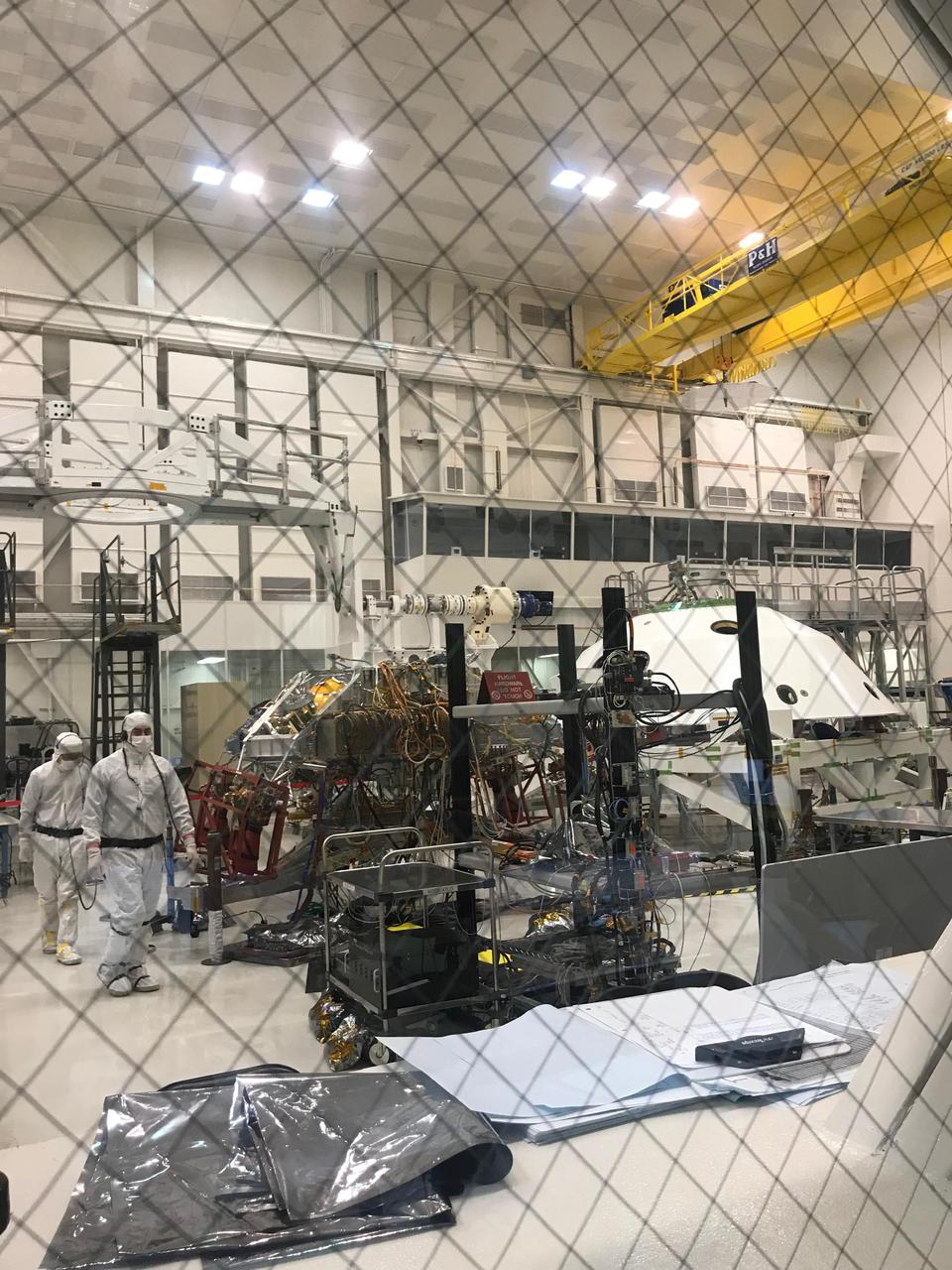
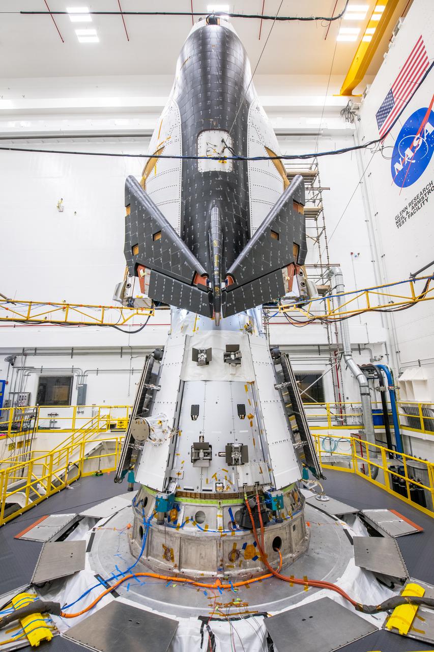
The Artemis I Orion crew module, now known as the Orion Environmental Test Article (ETA), arrives to NASA’s Kennedy Space Center in Florida on Saturday, Dec. 21, 2024, following an 11-month test campaign at NASA’s Neil Armstrong Test Facility in Sandusky, Ohio. The ETA will undergo propulsion functional testing at Kennedy’s Multi Payload Processing Facility. The ETA splashed down in the Pacific Ocean on Sunday, Dec. 11, 2022, following its journey around the Moon during the Artemis I mission.
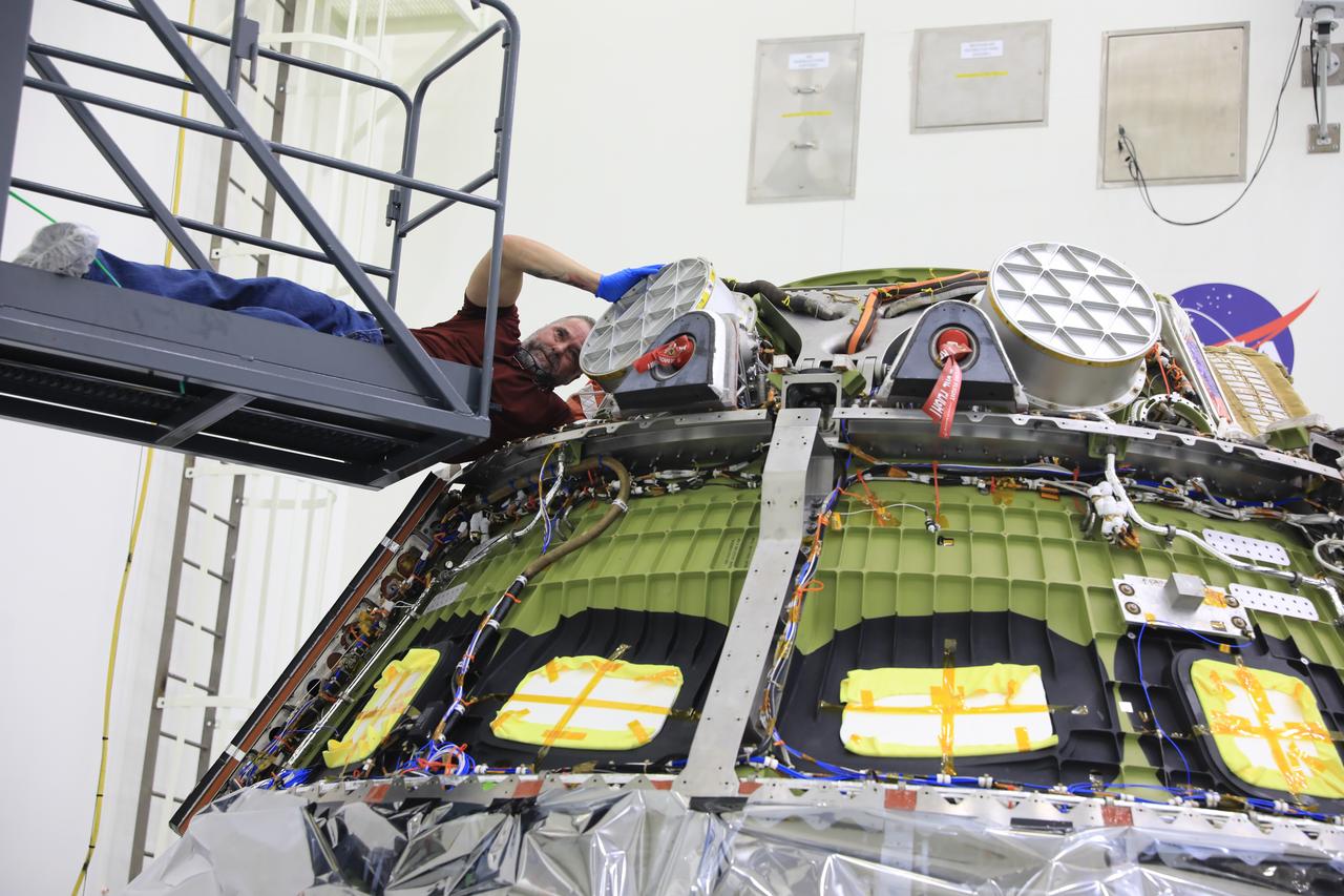
The Artemis I Orion crew module, now known as the Orion Environmental Test Article (ETA), arrives to NASA’s Kennedy Space Center in Florida on Saturday, Dec. 21, 2024, following an 11-month test campaign at NASA’s Neil Armstrong Test Facility in Sandusky, Ohio. The ETA will undergo propulsion functional testing at Kennedy’s Multi Payload Processing Facility. The ETA splashed down in the Pacific Ocean on Sunday, Dec. 11, 2022, following its journey around the Moon during the Artemis I mission.
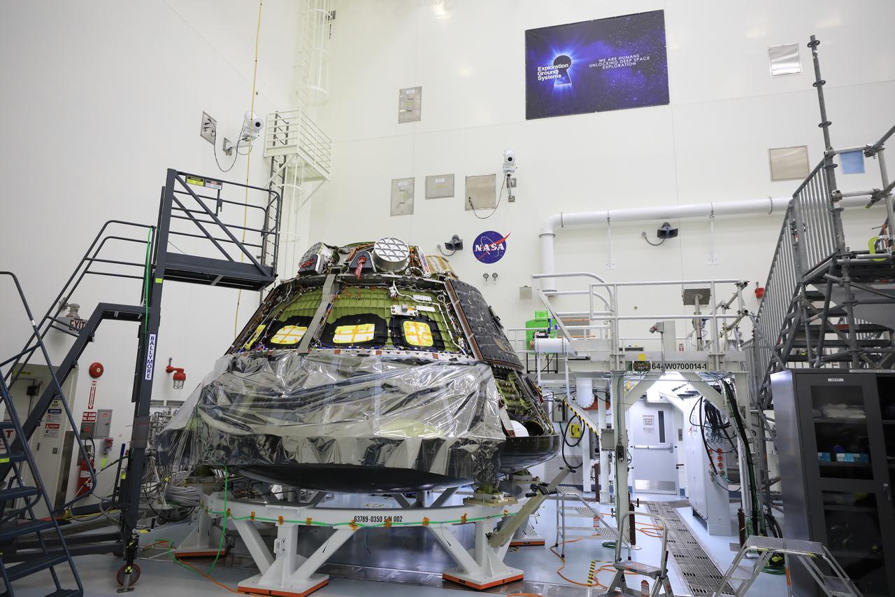
The Artemis I Orion crew module, now known as the Orion Environmental Test Article (ETA), arrives to NASA’s Kennedy Space Center in Florida on Saturday, Dec. 21, 2024, following an 11-month test campaign at NASA’s Neil Armstrong Test Facility in Sandusky, Ohio. The ETA will undergo propulsion functional testing at Kennedy’s Multi Payload Processing Facility. The ETA splashed down in the Pacific Ocean on Sunday, Dec. 11, 2022, following its journey around the Moon during the Artemis I mission.
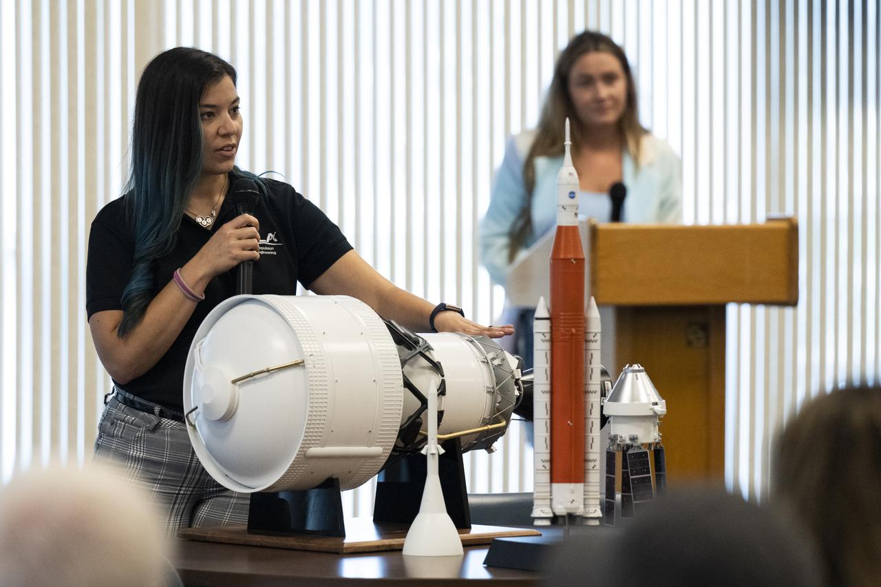
Interim Cryogenic Propulsive Stage (ICPS) Propulsion Lead at United Launch Alliance Julia Paez delivers remarks during a panel discussion with NASA Social attendees, Saturday, Aug. 27, 2022, at the Space Station Processing Facility at NASA’s Kennedy Space Center in Florida. NASA’s Artemis I flight test is the first integrated flight test of the agency’s deep space exploration systems: the Orion spacecraft, Space Launch System (SLS) rocket, and ground systems. Launch of the uncrewed flight test is targeted for no earlier than Aug. 29 at 8:33 a.m. ET. Photo Credit: (NASA/Keegan Barber)

A Wright Aeronautical XRJ47-W-5 ramjet installed in a test chamber of the National Advisory Committee for Aeronautics’ (NACA) new Propulsion Systems Laboratory at the Lewis Flight Propulsion Laboratory. Construction of the facility had only recently been completed, and NACA engineers were still testing the various operating systems. The Propulsion Systems Laboratory was the NACA’s most powerful facility for testing full-scale engines in simulated flight altitudes. It contained two 14-foot diameter and 100-foot-long altitude chambers that ran parallel to one another with a control room in between. The engine being tested was installed inside the test section of one of the chambers, seen in this photograph. Extensive instrumentation was fitted onto the engine prior to the test. Once the chamber was sealed, the altitude conditions were introduced, and the engine was ignited. Operators in the control room could run the engine at the various speeds and adjust the altitude conditions to the desired levels. The engine’s exhaust was ejected into the cooling equipment. Two 48-inch diameter XRJ47-W-5 ramjets were used to power the North American Aviation Navaho Missile. The Navaho was a winged missile that was intended to travel up to 3000 miles carrying a nuclear warhead. It was launched using rocket booster engines that were ejected after the missile’s ramjet engines were ignited.
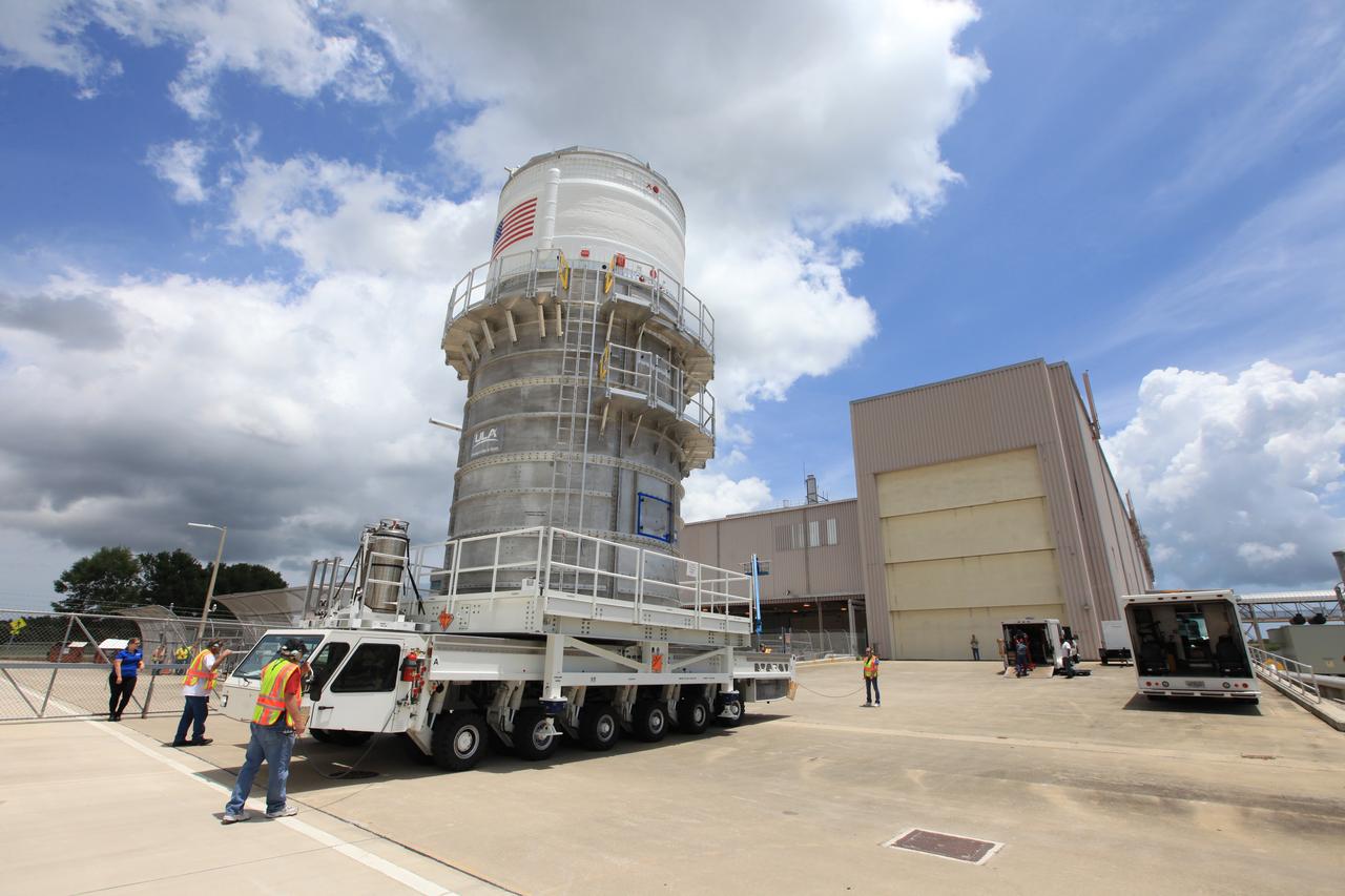
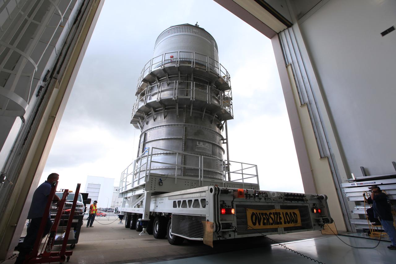
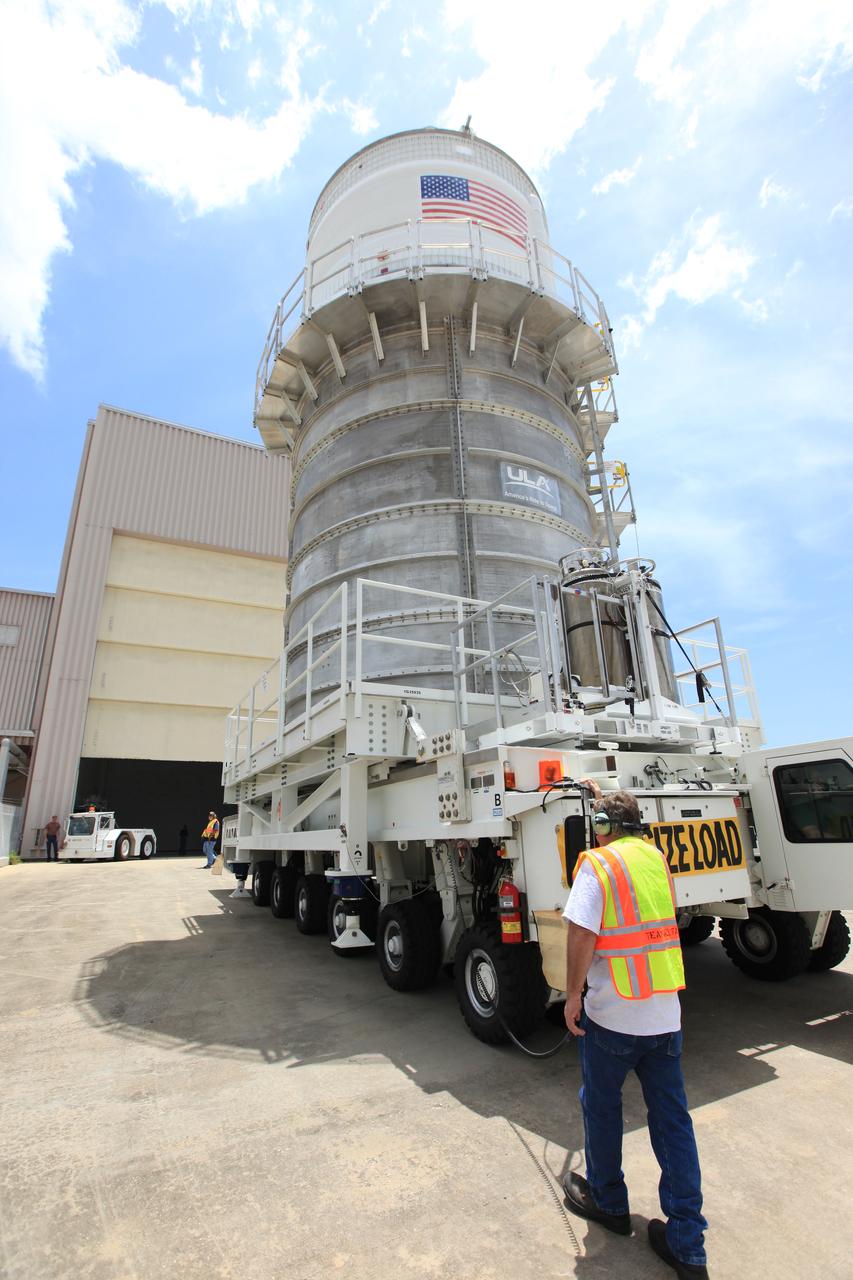
Packed inside its canister, the Interim Cryogenic Propulsion Stage (ICPS) for NASA's Space Launch System (SLS) rocket arrives at the low bay entrance of the Space Station Processing Facility at NASA's Kennedy Space Center in Florida. The ICPS is the first integrated piece of flight hardware to arrive for the SLS. It is the in-space stage that is located toward the top of the rocket, between the Launch Vehicle Stage Adapter and the Orion Spacecraft Adapter. It will provide some of the in-space propulsion during Orion's first flight test atop the SLS on Exploration Mission-1.
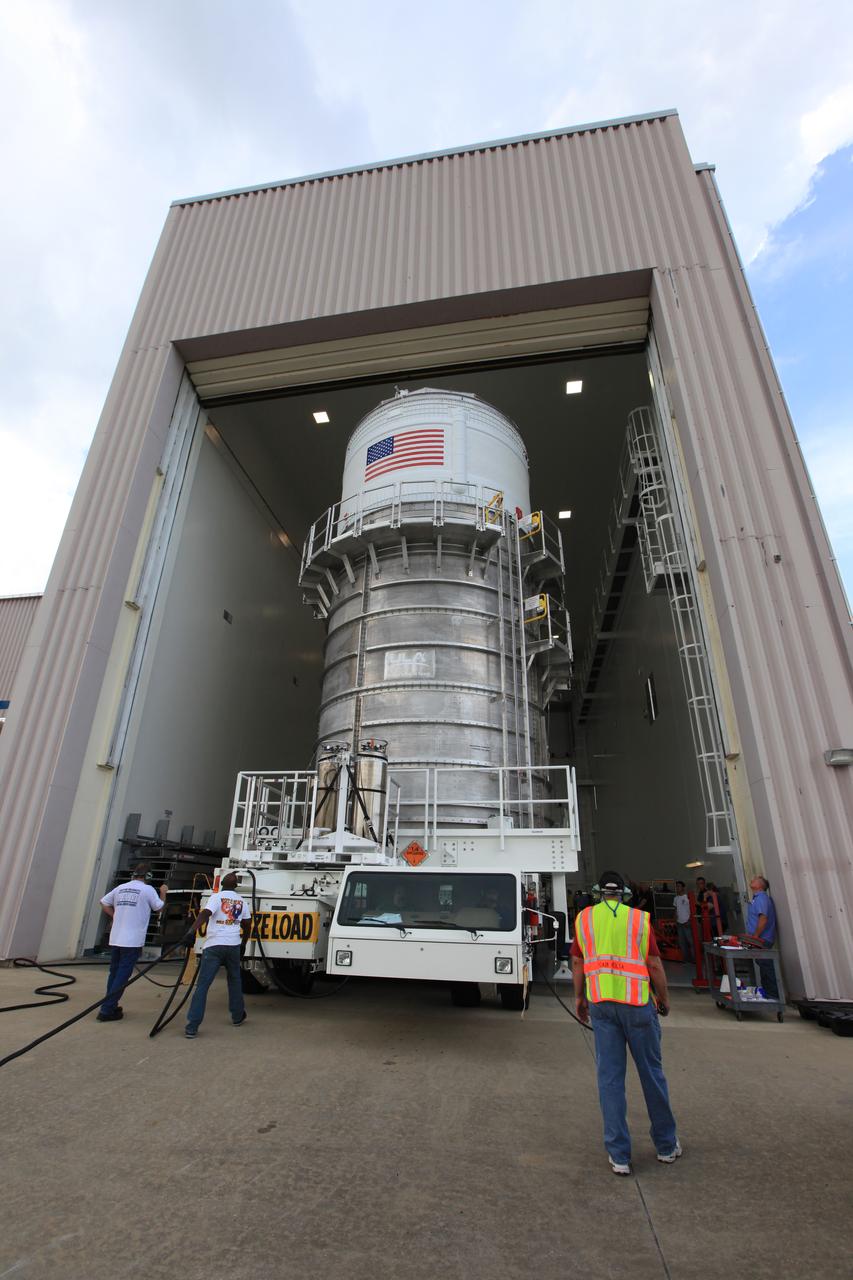
Packed inside its canister, the Interim Cryogenic Propulsion Stage (ICPS) for NASA's Space Launch System (SLS) rocket is moved into the low bay entrance of the Space Station Processing Facility at NASA's Kennedy Space Center in Florida. The ICPS is the first integrated piece of flight hardware to arrive for the SLS. It is the in-space stage that is located toward the top of the rocket, between the Launch Vehicle Stage Adapter and the Orion Spacecraft Adapter. It will provide some of the in-space propulsion during Orion's first flight test atop the SLS on Exploration Mission-1.
Packed inside its canister, the Interim Cryogenic Propulsion Stage (ICPS) for NASA's Space Launch System (SLS) rocket is moved into the low bay entrance of the Space Station Processing Facility at NASA's Kennedy Space Center in Florida. The ICPS is the first integrated piece of flight hardware to arrive for the SLS. It is the in-space stage that is located toward the top of the rocket, between the Launch Vehicle Stage Adapter and the Orion Spacecraft Adapter. It will provide some of the in-space propulsion during Orion's first flight test atop the SLS on Exploration Mission-1.
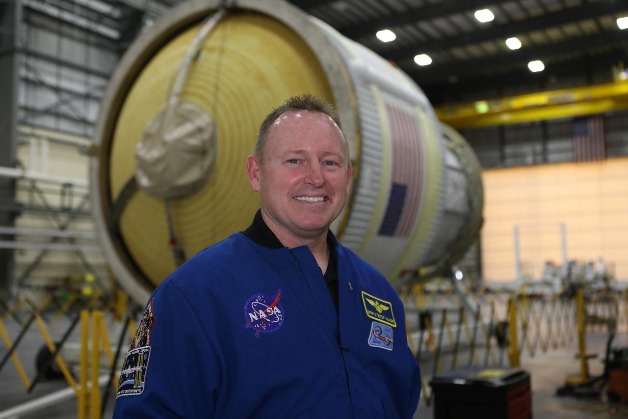
Inside the United Launch Alliance Horizontal Integration Facility at Cape Canaveral Air Force Station in Florida, NASA astronaut Barry "Butch" Wilmore views the first integrated piece of flight hardware for NASA's Space Launch System (SLS) rocket, the Interim Cryogenic Propulsion Stage (ICPS). The ICPS is the in-space stage that is located toward the top of the rocket, between the Launch Vehicle Stage Adapter and the Orion Spacecraft Adapter. It will provide some of the in-space propulsion during Orion's first flight test atop the SLS on Exploration Mission 1.
Packed inside its canister, the Interim Cryogenic Propulsion Stage (ICPS) for NASA's Space Launch System (SLS) rocket arrives at the low bay entrance of the Space Station Processing Facility at NASA's Kennedy Space Center in Florida. The ICPS is the first integrated piece of flight hardware to arrive for the SLS. It is the in-space stage that is located toward the top of the rocket, between the Launch Vehicle Stage Adapter and the Orion Spacecraft Adapter. It will provide some of the in-space propulsion during Orion's first flight test atop the SLS on Exploration Mission-1.
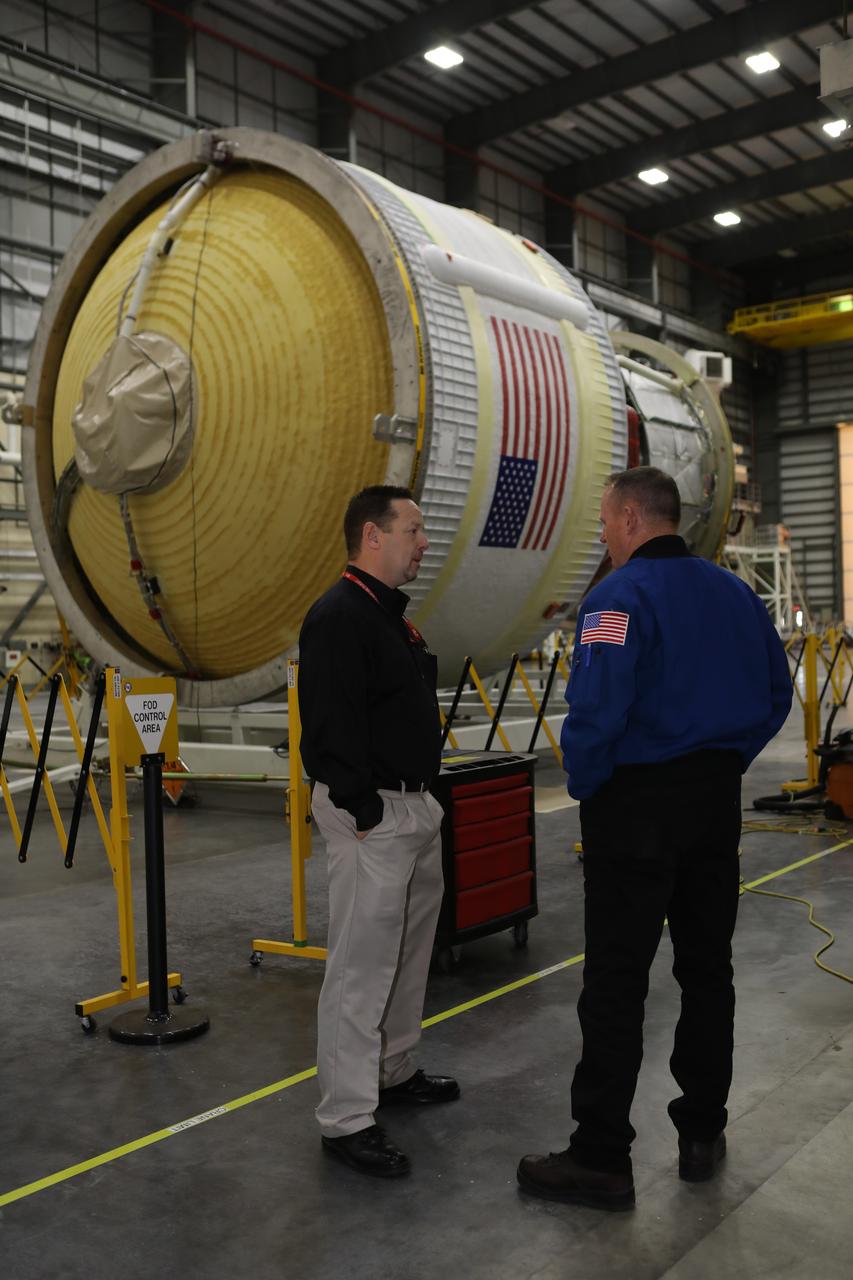
Inside the United Launch Alliance Horizontal Integration Facility at Cape Canaveral Air Force Station in Florida, NASA astronaut Barry "Butch" Wilmore views the first integrated piece of flight hardware for NASA's Space Launch System (SLS) rocket, the Interim Cryogenic Propulsion Stage (ICPS). The ICPS is the in-space stage that is located toward the top of the rocket, between the Launch Vehicle Stage Adapter and the Orion Spacecraft Adapter. It will provide some of the in-space propulsion during Orion's first flight test atop the SLS on Exploration Mission 1.
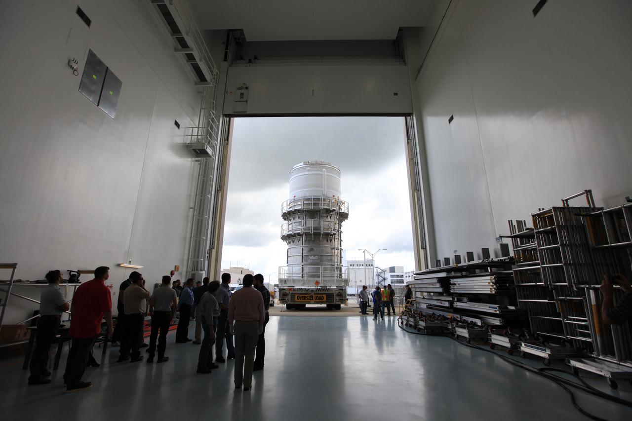
Packed inside its canister, the Interim Cryogenic Propulsion Stage (ICPS) for NASA's Space Launch System (SLS) rocket arrives at the low bay entrance of the Space Station Processing Facility at NASA's Kennedy Space Center in Florida. The ICPS is the first integrated piece of flight hardware to arrive for the SLS. It is the in-space stage that is located toward the top of the rocket, between the Launch Vehicle Stage Adapter and the Orion Spacecraft Adapter. It will provide some of the in-space propulsion during Orion's first flight test atop the SLS on Exploration Mission-1.
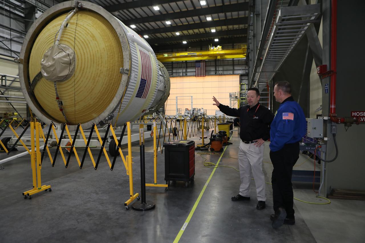
Inside the United Launch Alliance Horizontal Integration Facility at Cape Canaveral Air Force Station in Florida, NASA astronaut Barry "Butch" Wilmore views the first integrated piece of flight hardware for NASA's Space Launch System (SLS) rocket, the Interim Cryogenic Propulsion Stage (ICPS). The ICPS is the in-space stage that is located toward the top of the rocket, between the Launch Vehicle Stage Adapter and the Orion Spacecraft Adapter. It will provide some of the in-space propulsion during Orion's first flight test atop the SLS on Exploration Mission 1.
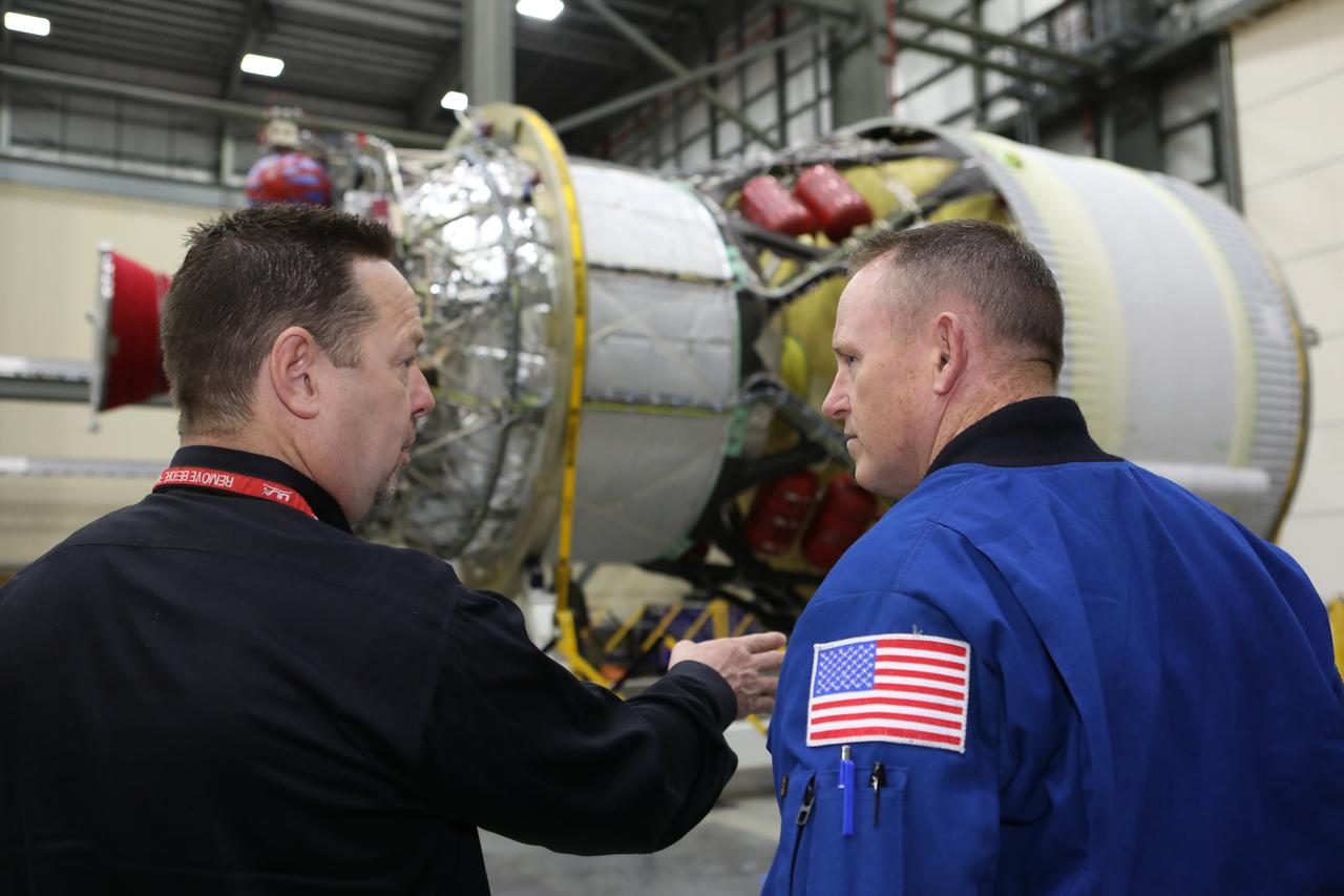
Inside the United Launch Alliance Horizontal Integration Facility at Cape Canaveral Air Force Station in Florida, NASA astronaut Barry "Butch" Wilmore views the first integrated piece of flight hardware for NASA's Space Launch System (SLS) rocket, the Interim Cryogenic Propulsion Stage (ICPS). The ICPS is the in-space stage that is located toward the top of the rocket, between the Launch Vehicle Stage Adapter and the Orion Spacecraft Adapter. It will provide some of the in-space propulsion during Orion's first flight test atop the SLS on Exploration Mission 1.
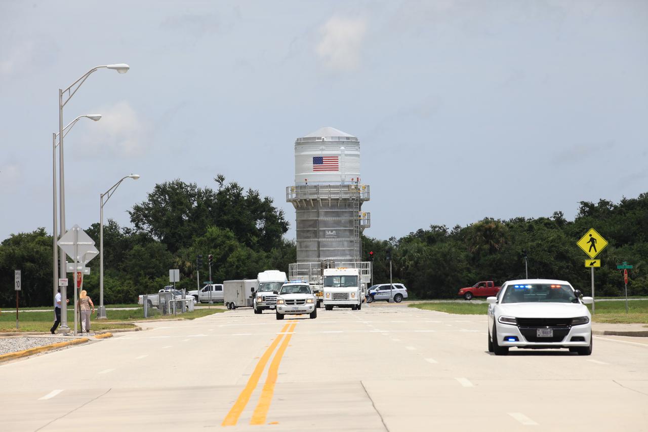
Packed inside its canister, the Interim Cryogenic Propulsion Stage (ICPS) for NASA's Space Launch System (SLS) rocket is being transported to the Space Station Processing Facility at NASA's Kennedy Space Center in Florida. The ICPS is the first integrated piece of flight hardware to arrive for the SLS. It is the in-space stage that is located toward the top of the rocket, between the Launch Vehicle Stage Adapter and the Orion Spacecraft Adapter. It will provide some of the in-space propulsion during Orion's first flight test atop the SLS on Exploration Mission-1.
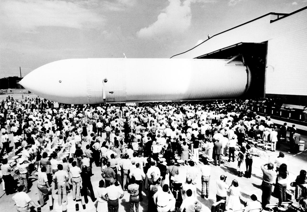
The first Space Shuttle External Tank, the Main Propulsion Test Article (MPTA), rolls off the assembly line September 9, 1977 at the Michoud Assembly Facility in New Orleans. The MPTA was then transported to the National Space Technology Laboratories in southern Mississippi where it was used in the first static firing of the three main engines. Marshall Space Flight Center had management responsibility for Space Shuttle propulsion elements, including the External Tank. Martin Marietta was the prime contractor who designed and assembled the tanks at Michoud.
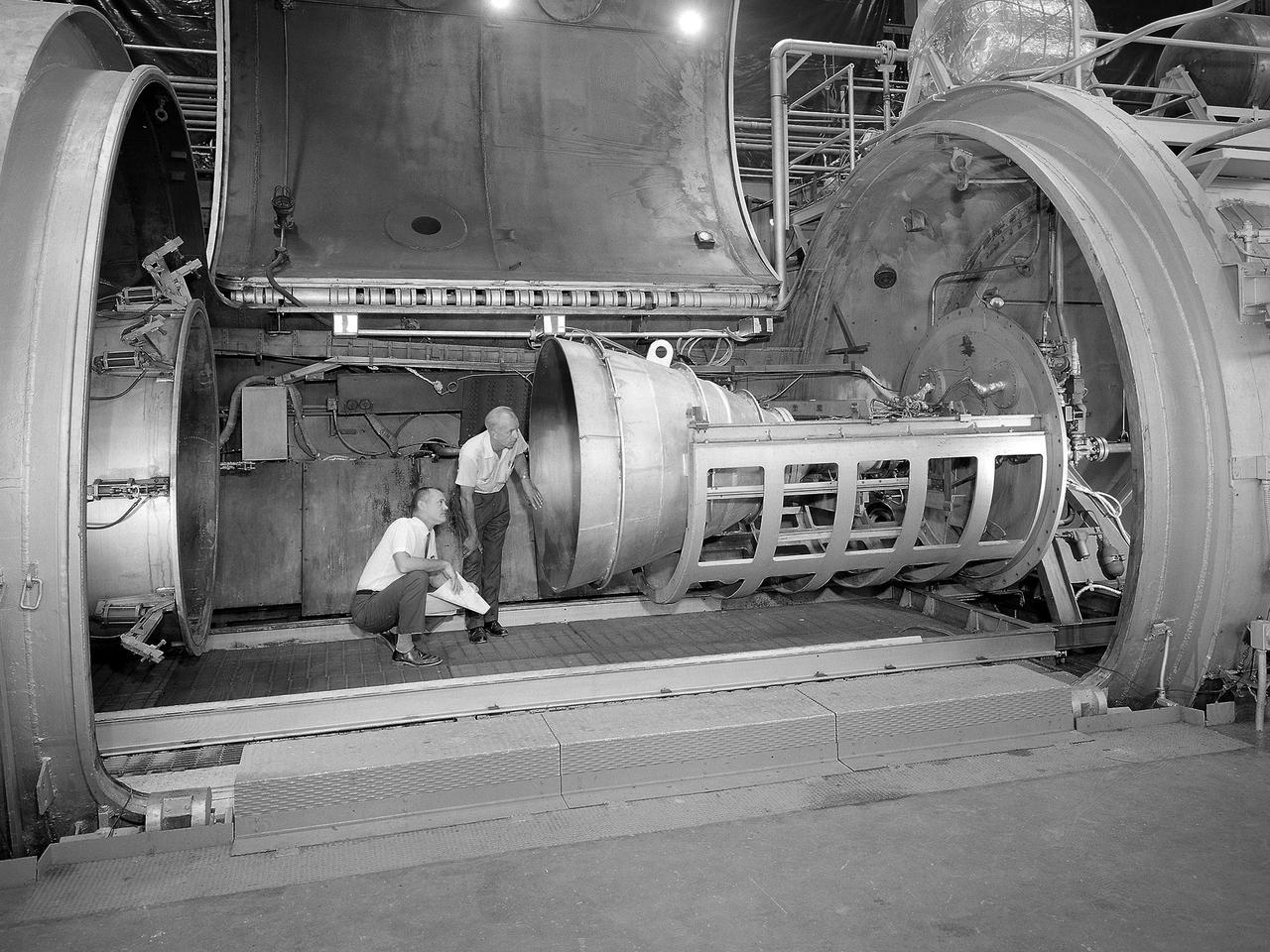
Bill Harrison and Bud Meilander check the setup of an Apollo Contour rocket nozzle in the Propulsion Systems Laboratory at the National Aeronautics and Space Administration (NASA) Lewis Research Center. The Propulsion Systems Laboratory contained two 14-foot diameter test chambers that could simulate conditions found at very high altitudes. The facility was used in the 1960s to study complex rocket engines such as the Pratt and Whitney RL-10 and rocket components such as the Apollo Contour nozzle, seen here. Meilander oversaw the facility’s mechanics and the installation of test articles into the chambers. Harrison was head of the Supersonic Tunnels Branch in the Test Installations Division. Researchers sought to determine the impulse value of the storable propellant mix, classify and improve the internal engine performance, and compare the results with analytical tools. A special setup was installed in the chamber that included a device to measure the thrust load and a calibration stand. Both cylindrical and conical combustion chambers were examined with the conical large area ratio nozzles. In addition, two contour nozzles were tested, one based on the Apollo Service Propulsion System and the other on the Air Force’s Titan transtage engine. Three types of injectors were investigated, including a Lewis-designed model that produced 98-percent efficiency. It was determined that combustion instability did not affect the nozzle performance. Although much valuable information was obtained during the tests, attempts to improve the engine performance were not successful.
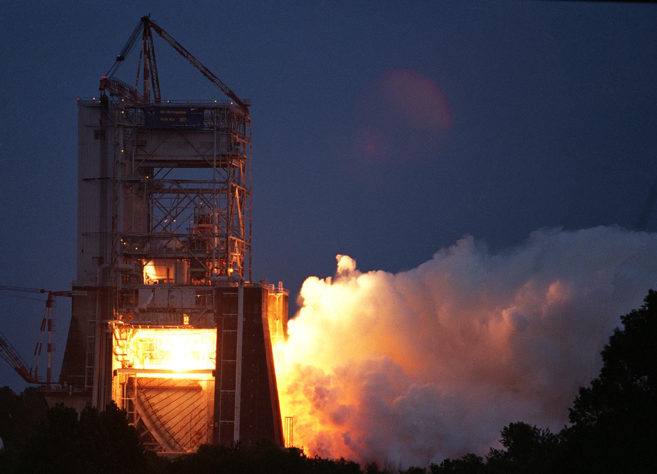
NASA engineers successfully tested a Russian-built rocket engine on November 4, 1998 at the Marshall Space Flight Center (MSFC) Advanced Engine Test Facility, which had been used for testing the Saturn V F-1 engines and Space Shuttle Main engines. The MSFC was under a Space Act Agreement with Lockheed Martin Astronautics of Denver to provide a series of test firings of the Atlas III propulsion system configured with the Russian-designed RD-180 engine. The tests were designed to measure the performance of the Atlas III propulsion system, which included avionics and propellant tanks and lines, and how these components interacted with the RD-180 engine. The RD-180 is powered by kerosene and liquid oxygen, the same fuel mix used in Saturn rockets. The RD-180, the most powerful rocket engine tested at the MSFC since Saturn rocket tests in the 1960s, generated 860,000 pounds of thrust.
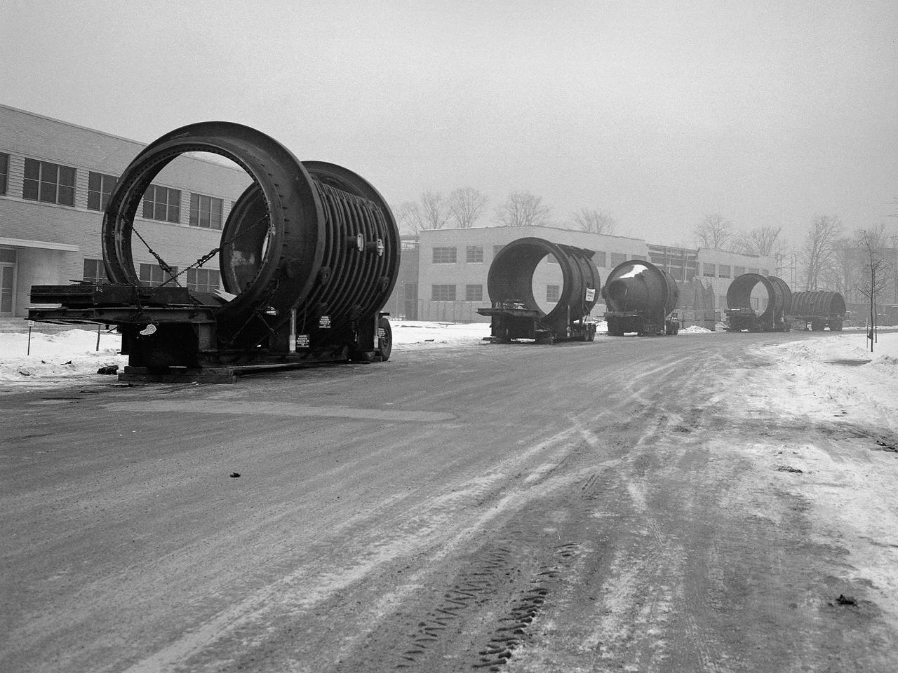
A caravan of large steel castings arrived at the National Advisory Committee for Aeronautics (NACA) Lewis Flight Propulsion Laboratory in January 1951. These pieces would serve as the two 14-foot diameter test chambers in the new Propulsion Systems Laboratory (PSL). NACA Lewis specialized in aircraft engines and offered many engine test facilities. In the late 1940s, however, the NACA realized a larger facility was required to test the newest jet engines. When completed in October 1952, PSL became the nation’s most powerful facility for testing full-scale engines at simulated flight altitudes. NACA engineers began designing the PSL in 1947, and excavations commenced in September 1949. In the spring of 1950, the facility’s supports were erected, and the two large exhaust gas coolers were installed. Work on the Access Building began in early 1951 with the arrival of the large test section pieces, seen in this photograph. The massive pieces were delivered to the area from the Henry Pratt Company by rail and then loaded on a series of flatbed trucks that transported them to Lewis. The nearest vehicle has one of the clamshell access hatches. PSL was initially used to study the jet engines of the early 1950s and ramjets for missile programs such as Navaho and Bomarc. With the advent of the space program in the late 1950s, the facility was used to investigate complex rocket engines, including the Pratt and Whitney RL-10.

On Feb. 21, 2017 engineers successfully install ESA’s European Service Module Propulsion Qualification Module (PQM) at NASA’s White Sands Test Facility in New Mexico that was delivered by Airbus – ESA’s prime contractor for the Service Module. The module will be equipped with a total of 21 engines to support NASA’s Orion spacecraft: one U.S. Space Shuttle Orbital Maneuvering System (OMS) engine, eight auxiliary thrusters and 12 smaller thrusters produced by Airbus Safran Launchers in Germany. The all-steel PQM structure is used to test the propulsion systems on Orion, including “hot firing” of the OMS engine and thrusters.

On Feb. 21, 2017 engineers successfully install ESA’s European Service Module Propulsion Qualification Module (PQM) at NASA’s White Sands Test Facility in New Mexico that was delivered by Airbus – ESA’s prime contractor for the Service Module. The module will be equipped with a total of 21 engines to support NASA’s Orion spacecraft: one U.S. Space Shuttle Orbital Maneuvering System (OMS) engine, eight auxiliary thrusters and 12 smaller thrusters produced by Airbus Safran Launchers in Germany. The all-steel PQM structure is used to test the propulsion systems on Orion, including “hot firing” of the OMS engine and thrusters.

On Feb. 22, engineers successfully install ESA’s European Service Module Propulsion Qualification Module (PQM) at NASA’s White Sands Test Facility in New Mexico that was delivered by Airbus – ESA’s prime contractor for the Service Module. The module will be equipped with a total of 21 engines to support NASA’s Orion spacecraft: one U.S. Space Shuttle Orbital Maneuvering System (OMS) engine, eight auxiliary thrusters and 12 smaller thrusters produced by Airbus Safran Launchers in Germany. The all-steel PQM structure is used to test the propulsion systems on Orion, including “hot firing” of the OMS engine and thrusters.
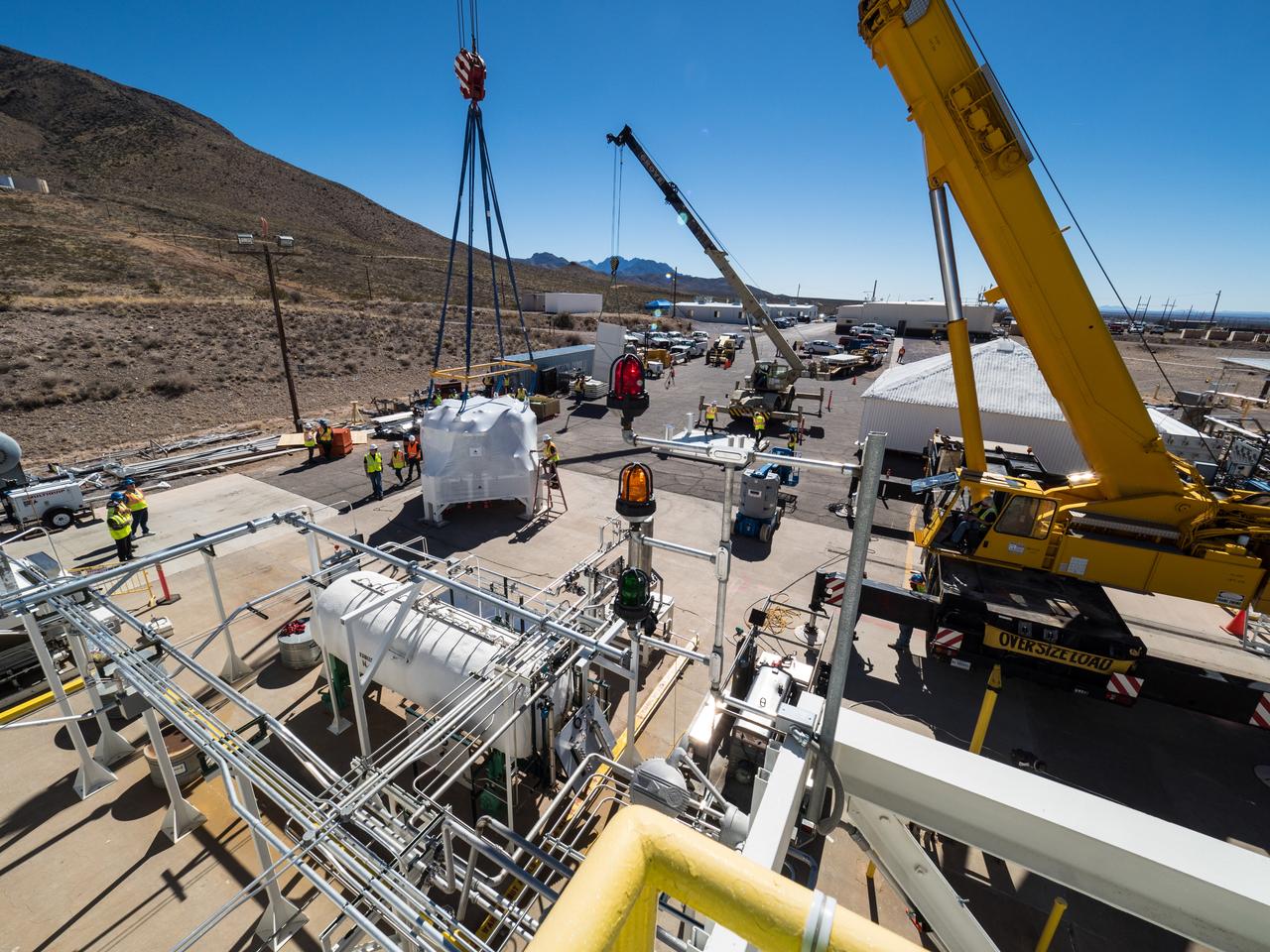
On Feb. 21, 2017 engineers successfully install ESA’s European Service Module Propulsion Qualification Module (PQM) at NASA’s White Sands Test Facility in New Mexico that was delivered by Airbus – ESA’s prime contractor for the Service Module. The module will be equipped with a total of 21 engines to support NASA’s Orion spacecraft: one U.S. Space Shuttle Orbital Maneuvering System (OMS) engine, eight auxiliary thrusters and 12 smaller thrusters produced by Airbus Safran Launchers in Germany. The all-steel PQM structure is used to test the propulsion systems on Orion, including “hot firing” of the OMS engine and thrusters.
On Feb. 21, 2017 engineers successfully install ESA’s European Service Module Propulsion Qualification Module (PQM) at NASA’s White Sands Test Facility in New Mexico that was delivered by Airbus – ESA’s prime contractor for the Service Module. The module will be equipped with a total of 21 engines to support NASA’s Orion spacecraft: one U.S. Space Shuttle Orbital Maneuvering System (OMS) engine, eight auxiliary thrusters and 12 smaller thrusters produced by Airbus Safran Launchers in Germany. The all-steel PQM structure is used to test the propulsion systems on Orion, including “hot firing” of the OMS engine and thrusters.