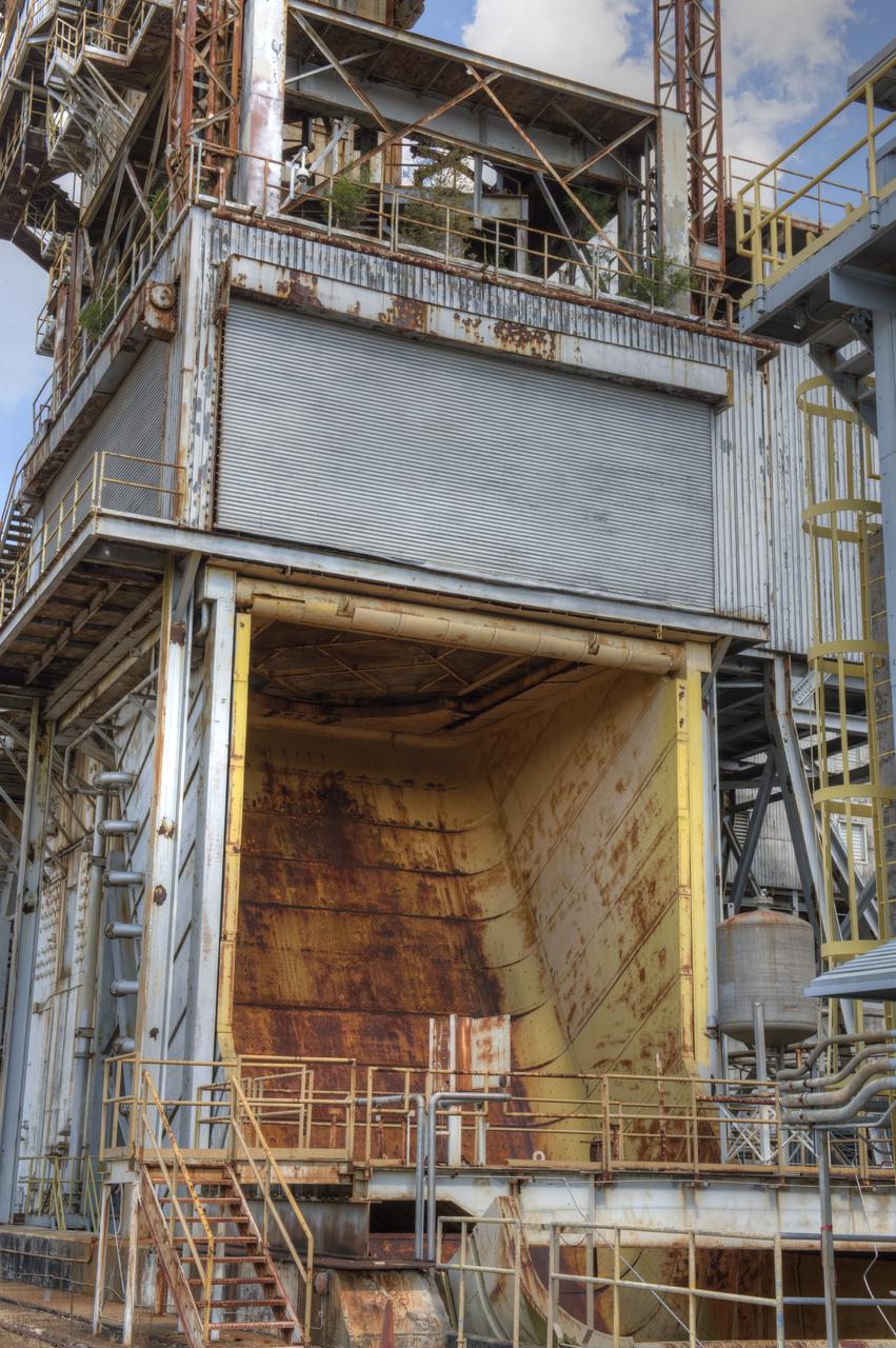
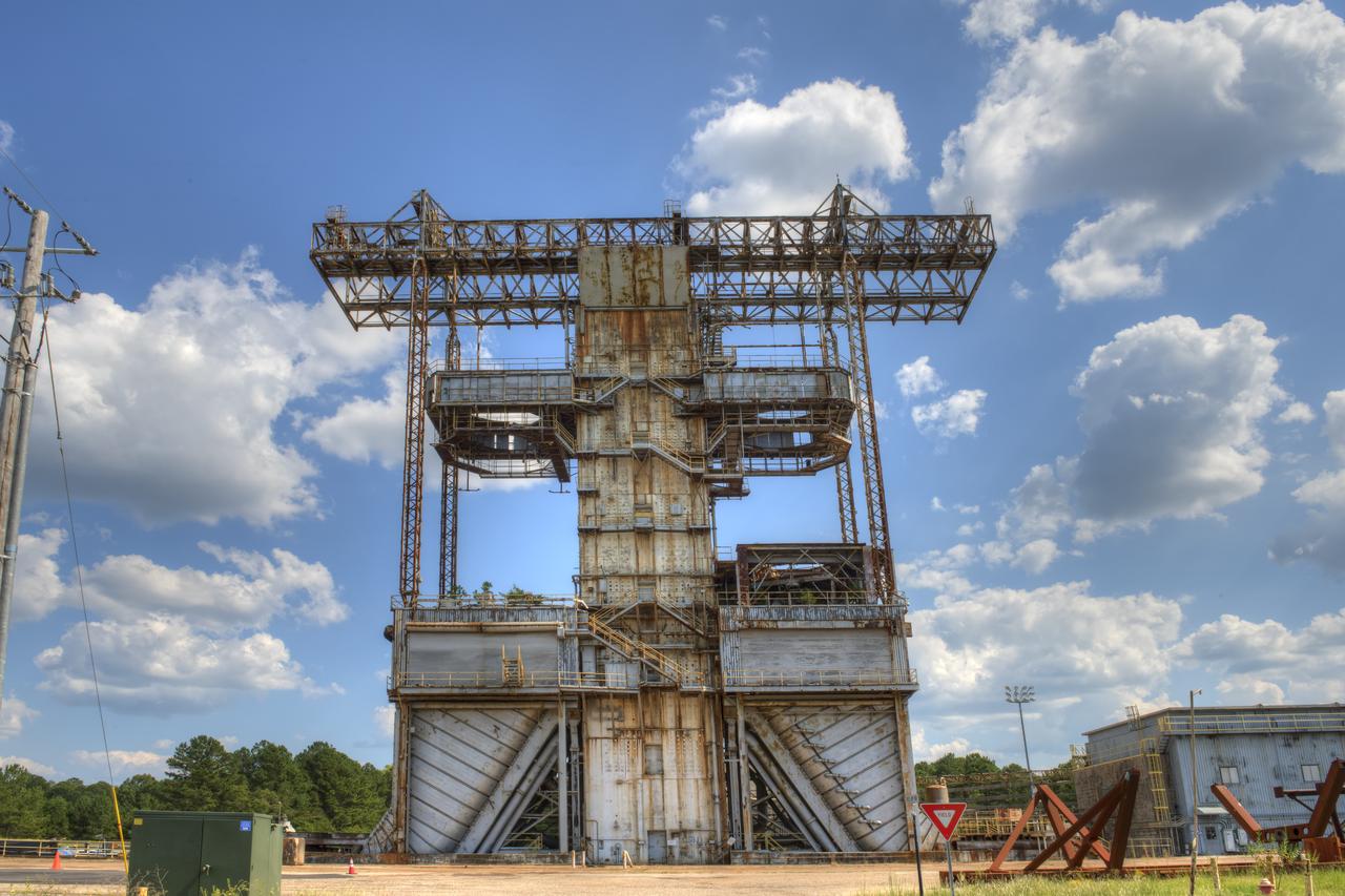
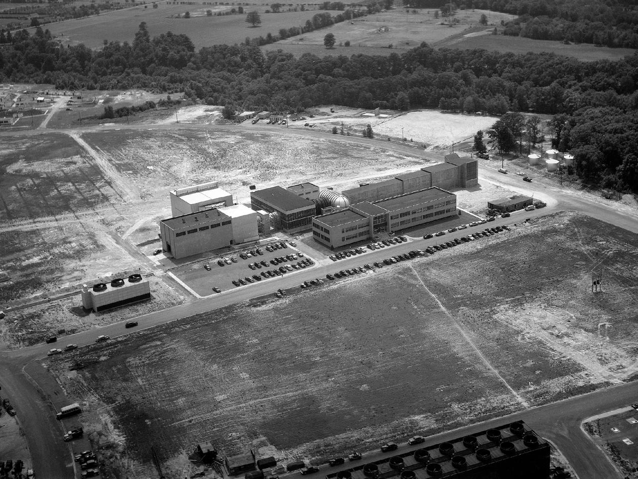
PROPULSION AND STRUCTURAL TEST FACILITY (BUILDING 4572) AT THE GEORGE C. MARSHALL SPACE FLIGHT CENTER IN HUNTSVILLE, ALABAMA
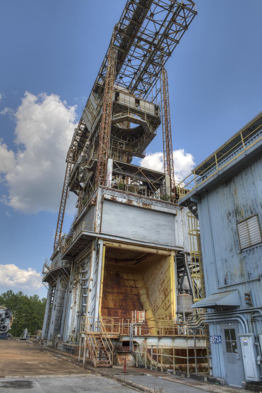
PROPULSION AND STRUCTURAL TEST FACILITY (BUILDING 4572) AT THE GEORGE C. MARSHALL SPACE FLIGHT CENTER IN HUNTSVILLE, ALABAMA
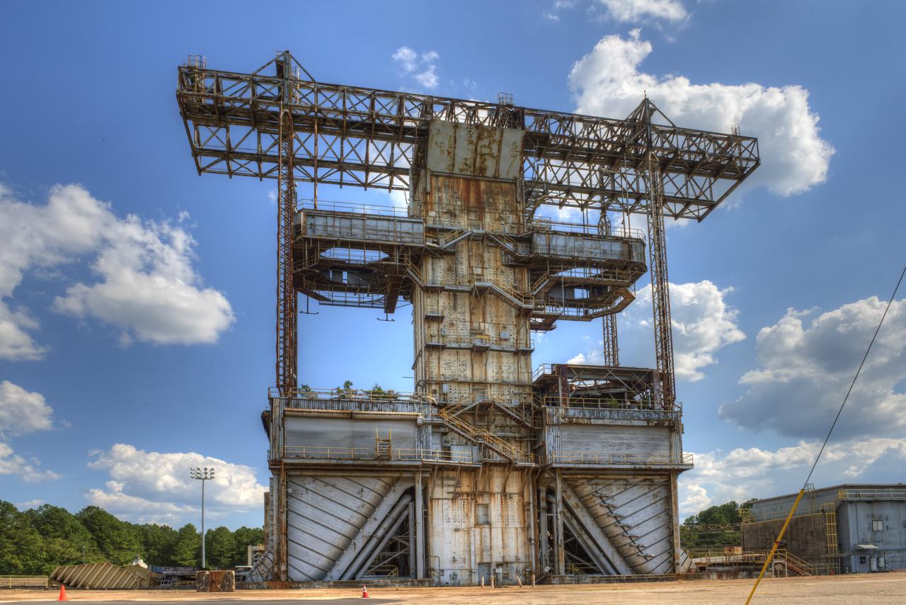
PROPULSION AND STRUCTURAL TEST FACILITY (BUILDING 4572) AT THE GEORGE C. MARSHALL SPACE FLIGHT CENTER IN HUNTSVILLE, ALABAMA
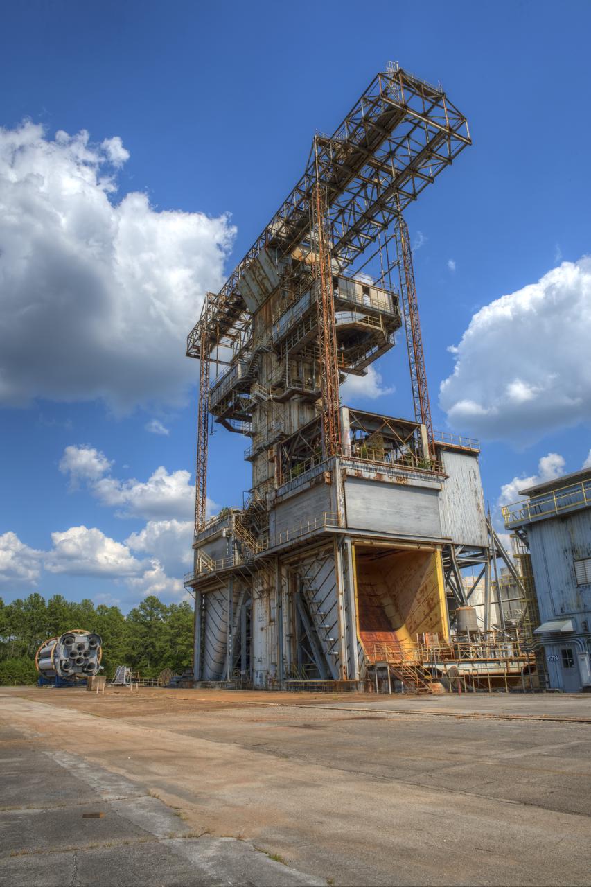
PROPULSION AND STRUCTURAL TEST FACILITY (BUILDING 4572) AT THE GEORGE C. MARSHALL SPACE FLIGHT CENTER IN HUNTSVILLE, ALABAMA
PROPULSION AND STRUCTURAL TEST FACILITY (BUILDING 4572) AT THE GEORGE C. MARSHALL SPACE FLIGHT CENTER IN HUNTSVILLE, ALABAMA
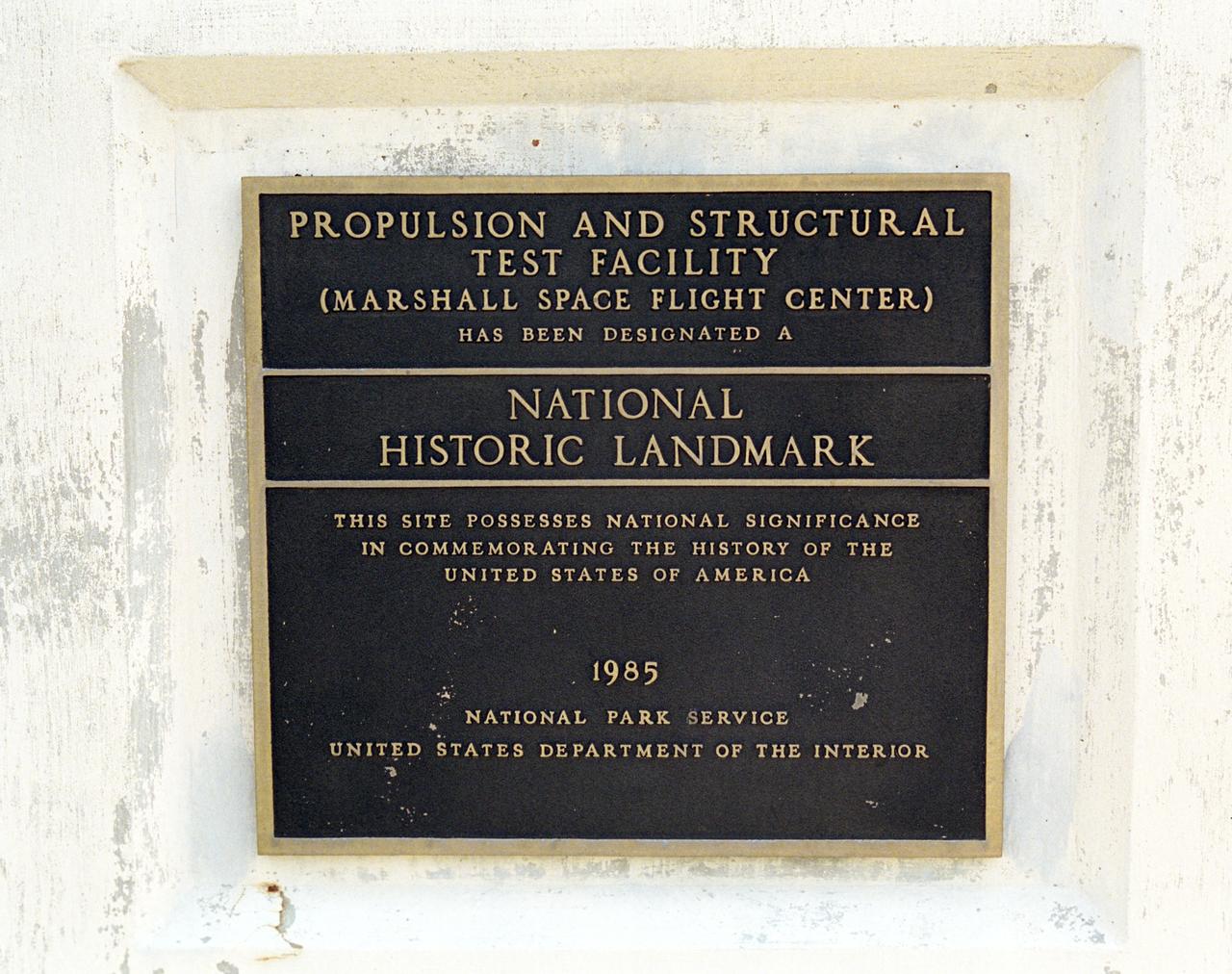
This plaque, displayed on the grounds of Marshall Space Flight Center in Huntsville, Alabama, commemorates the designation of the Propulsion and Structural Test Facility as a National Historic Landmark by the National Park Service of the United States Interior. The site was designated as a landmark in 1985.
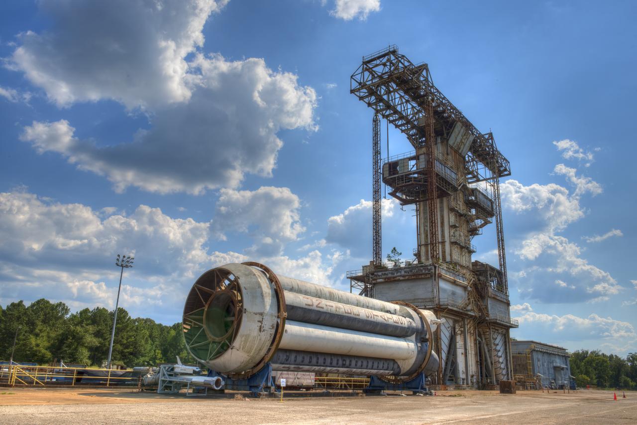
SATURN S-1B STAGE (SA-T) WITH PROPULSION AND STRUCTURAL TEST FACILITY (BUILDING 4572) IN BACKGROUND
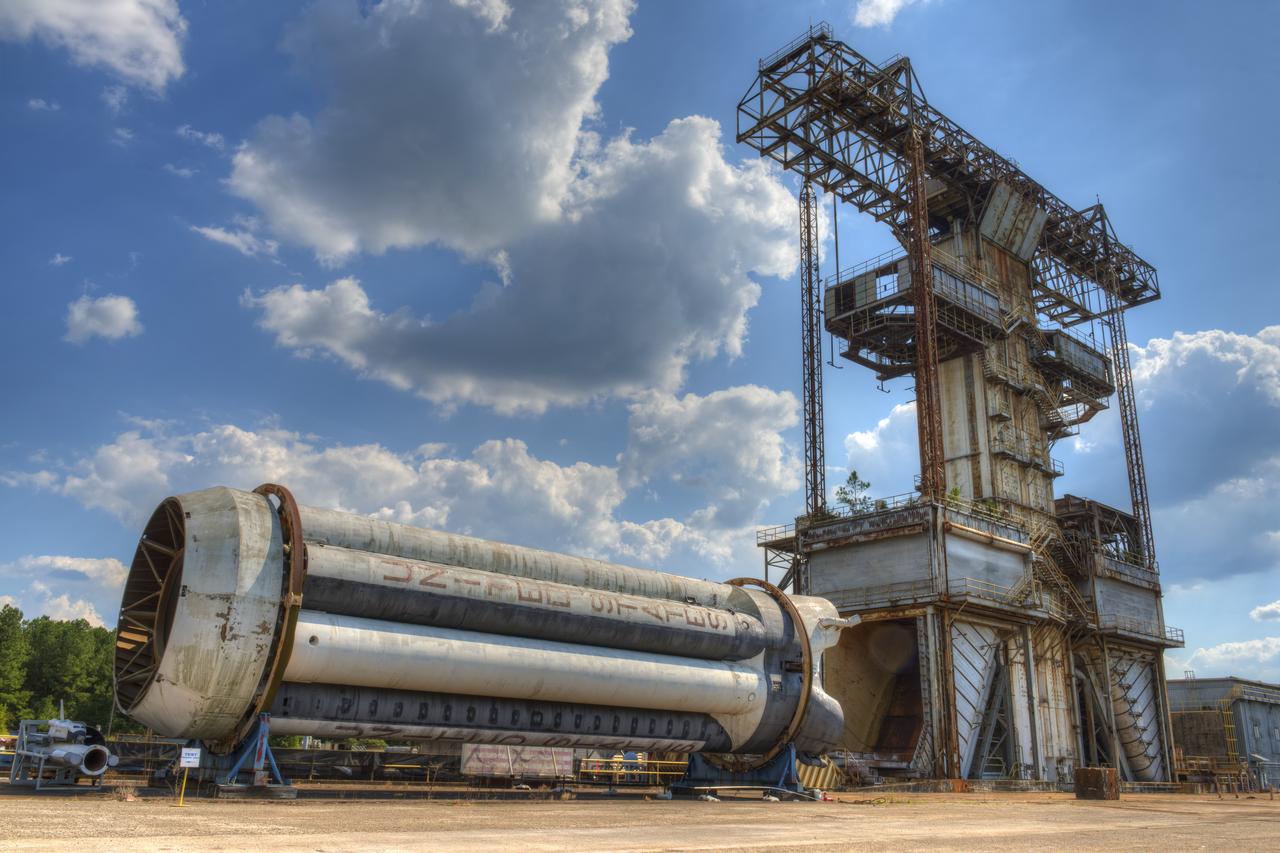
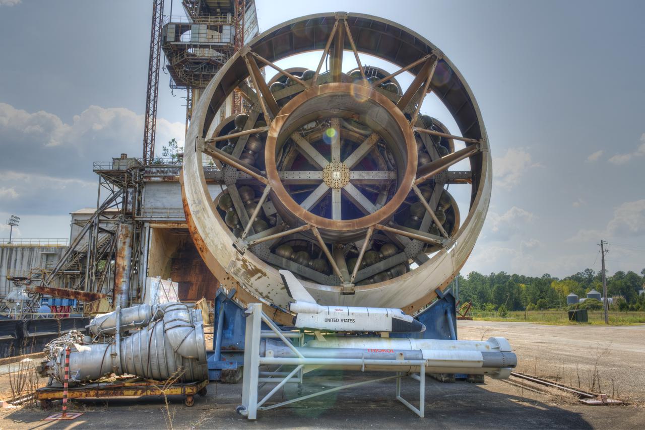
PROPULSION AND STRUCTURAL TEST FACILITY (BUILDING 4572) AT THE GEORGE C. MARSHALL SPACE FLIGHT CENTER IN HUNTSVILLE, ALABAMA WITH THE SATURN S-1B STAGE (SA-) IN FOREGROUND
FORWARD END OF SATURN S-1B STAGE (SA-T) NEAR PROPULSION AND STRUCTURAL TEST FACILITY (BUILDING 4572) AT THE GEORGE C. MARSHALL SPACE FLIGHT CENTER IN HUNTSVILLE, ALABAMA
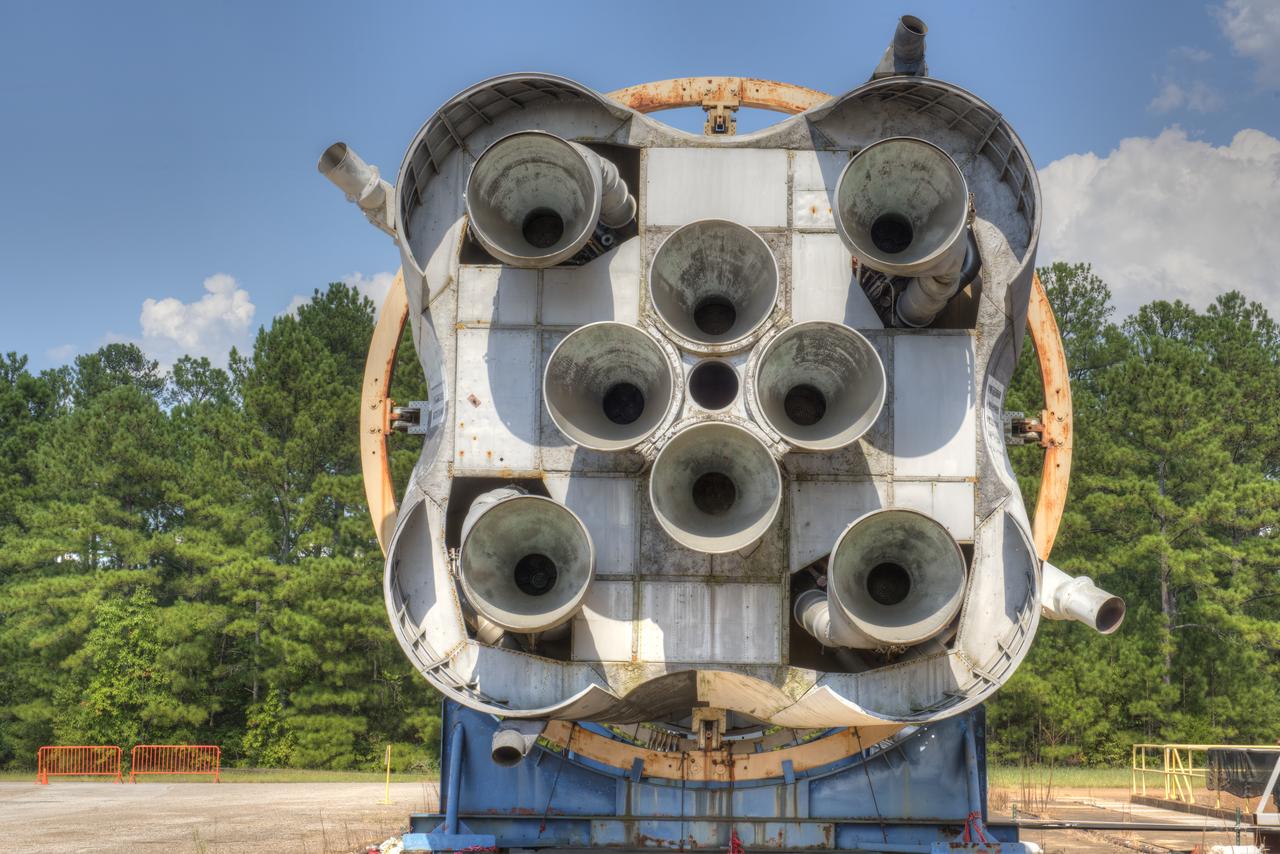
CLOSE-UP OF AFT END OF SATURN S-1B STAGE (SA-T) NEAR PROPULSION AND STRUCTURAL TEST FACILITY (BUILDING 4572) AT THE GEORGE C. MARSHALL SPACE FLIGHT CENTER IN HUNTSVILLE, ALABAMA.
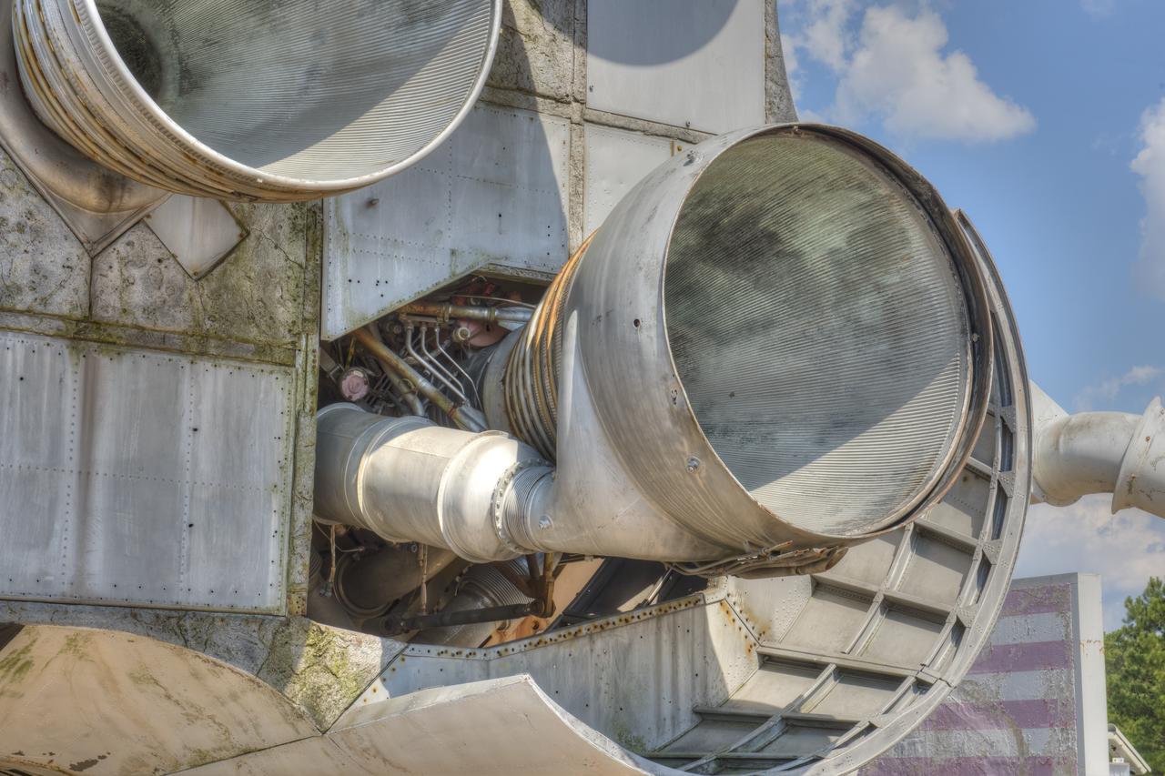
CLOSE-UP OF H-1 ENGINE INSTALLED ON SATURN S-1B STAGE (SA-T) NEAR PROPULSION AND STRUCTURAL TEST FACILITY (BUILDING 4572) AT THE GEORGE C. MARSHALL SPACE FLIGHT CENTER.
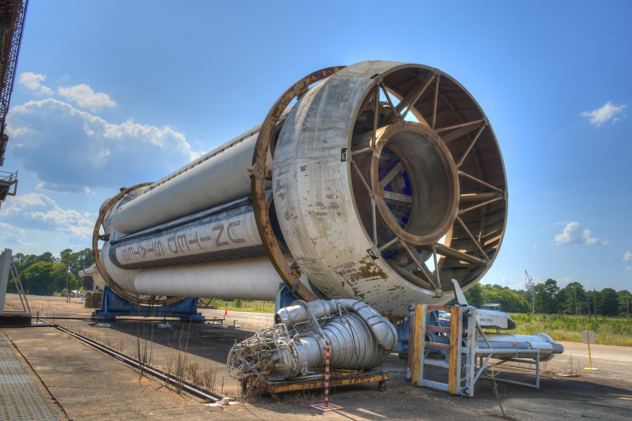
FORWARD END OF SATURN S-1B STAGE (SA-T) NEAR PROPULSION AND STRUCTURAL TEST FACILITY (BUILDING 4572) AT THE GEORGE C. MARSHALL SPACE FLIGHT CENTER IN HUNTSVILLE, ALABAMA
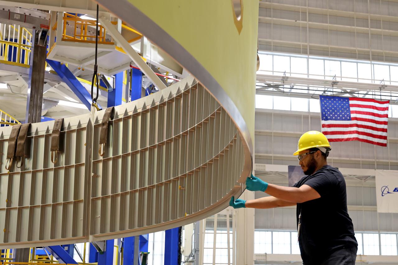
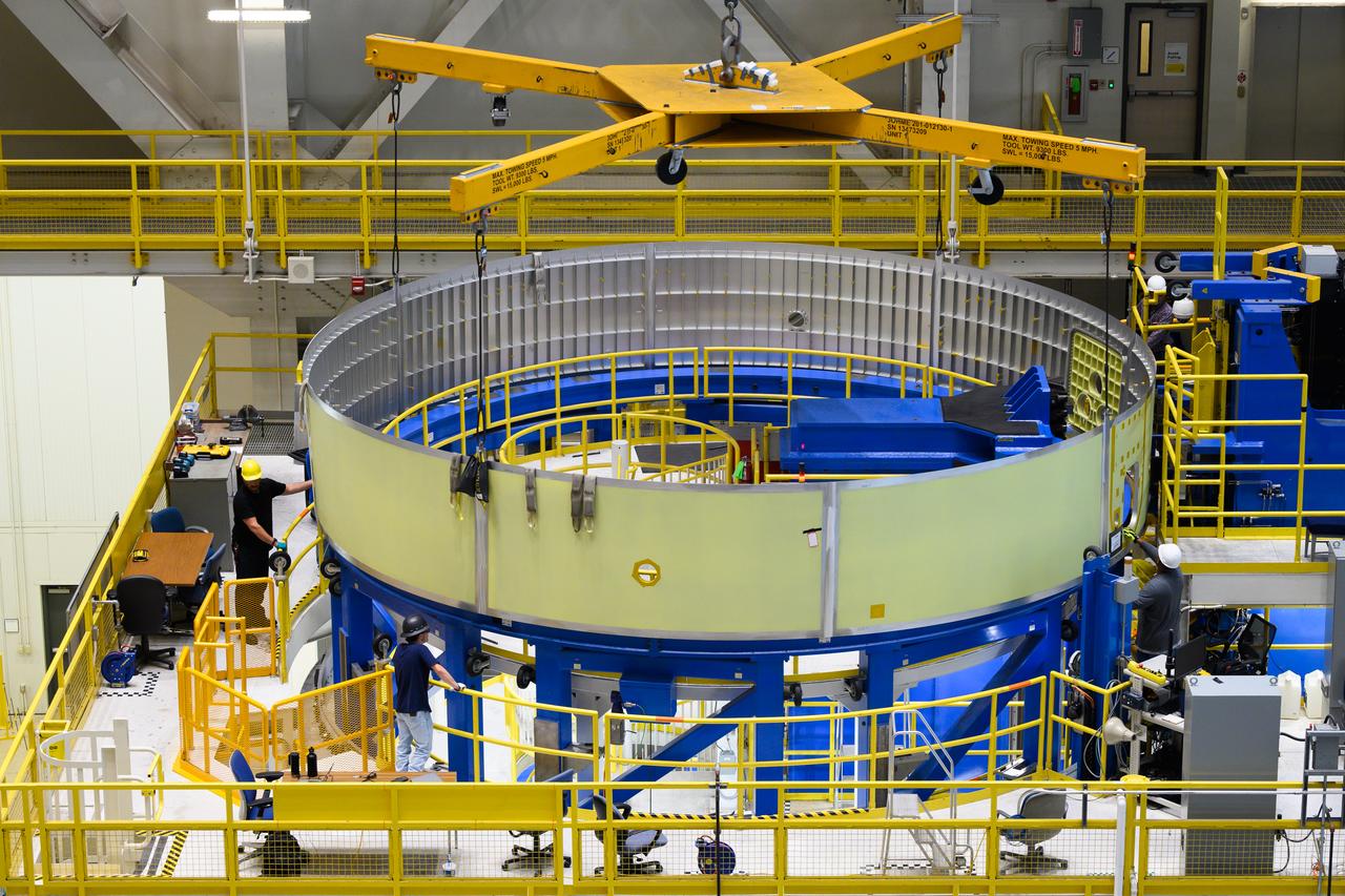
These images and videos show technicians at NASA’s Michoud Assembly Facility in New Orleans examining and lifting midbody barrels for the Exploration Upper Stage (EUS) structural test article of the SLS (Space Launch System) rocket in May 2023. The barrel sections make up the body, or main structure, of the future in-space propulsion stage for the mega rocket. The Exploration Upper Stage will be used on the second configuration of the SLS rocket, known as Block 1B, and will provide in-space propulsion to send astronauts in NASA’s Orion spacecraft and heavy cargo on a precise trajectory to the Moon. Beginning with Artemis IV, EUS will replace the interim cryogenic propulsion stage for the Block 1 configuration of SLS. It has larger propellant tanks and four RL10 engines, enabling SLS to launch 40% more cargo to the Moon along with crew. EUS flight hardware is in early production at Michoud. Crews with NASA and Boeing, the lead contractor for the SLS core stage and EUS, are also manufacturing the EUS structural test article. The test hardware is structurally identical to the flight version and will be used during a series of strenuous testing that simulates the forces the rocket will experience during launch and flight and verify its structural integrity. NASA is working to land the first woman and first person of color on the Moon under Artemis. SLS is part of NASA’s backbone for deep space exploration, along with Orion and the Gateway in orbit around the Moon. SLS is the only rocket that can send Orion, astronauts, and supplies to the Moon in a single mission.
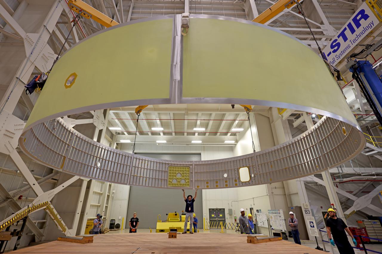
These images and videos show technicians at NASA’s Michoud Assembly Facility in New Orleans examining and lifting midbody barrels for the Exploration Upper Stage (EUS) structural test article of the SLS (Space Launch System) rocket in May 2023. The barrel sections make up the body, or main structure, of the future in-space propulsion stage for the mega rocket. The Exploration Upper Stage will be used on the second configuration of the SLS rocket, known as Block 1B, and will provide in-space propulsion to send astronauts in NASA’s Orion spacecraft and heavy cargo on a precise trajectory to the Moon. Beginning with Artemis IV, EUS will replace the interim cryogenic propulsion stage for the Block 1 configuration of SLS. It has larger propellant tanks and four RL10 engines, enabling SLS to launch 40% more cargo to the Moon along with crew. EUS flight hardware is in early production at Michoud. Crews with NASA and Boeing, the lead contractor for the SLS core stage and EUS, are also manufacturing the EUS structural test article. The test hardware is structurally identical to the flight version and will be used during a series of strenuous testing that simulates the forces the rocket will experience during launch and flight and verify its structural integrity. NASA is working to land the first woman and first person of color on the Moon under Artemis. SLS is part of NASA’s backbone for deep space exploration, along with Orion and the Gateway in orbit around the Moon. SLS is the only rocket that can send Orion, astronauts, and supplies to the Moon in a single mission.
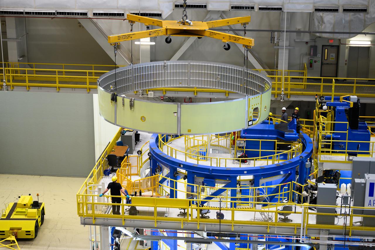
These images and videos show technicians at NASA’s Michoud Assembly Facility in New Orleans examining and lifting midbody barrels for the Exploration Upper Stage (EUS) structural test article of the SLS (Space Launch System) rocket in May 2023. The barrel sections make up the body, or main structure, of the future in-space propulsion stage for the mega rocket. The Exploration Upper Stage will be used on the second configuration of the SLS rocket, known as Block 1B, and will provide in-space propulsion to send astronauts in NASA’s Orion spacecraft and heavy cargo on a precise trajectory to the Moon. Beginning with Artemis IV, EUS will replace the interim cryogenic propulsion stage for the Block 1 configuration of SLS. It has larger propellant tanks and four RL10 engines, enabling SLS to launch 40% more cargo to the Moon along with crew. EUS flight hardware is in early production at Michoud. Crews with NASA and Boeing, the lead contractor for the SLS core stage and EUS, are also manufacturing the EUS structural test article. The test hardware is structurally identical to the flight version and will be used during a series of strenuous testing that simulates the forces the rocket will experience during launch and flight and verify its structural integrity. NASA is working to land the first woman and first person of color on the Moon under Artemis. SLS is part of NASA’s backbone for deep space exploration, along with Orion and the Gateway in orbit around the Moon. SLS is the only rocket that can send Orion, astronauts, and supplies to the Moon in a single mission.

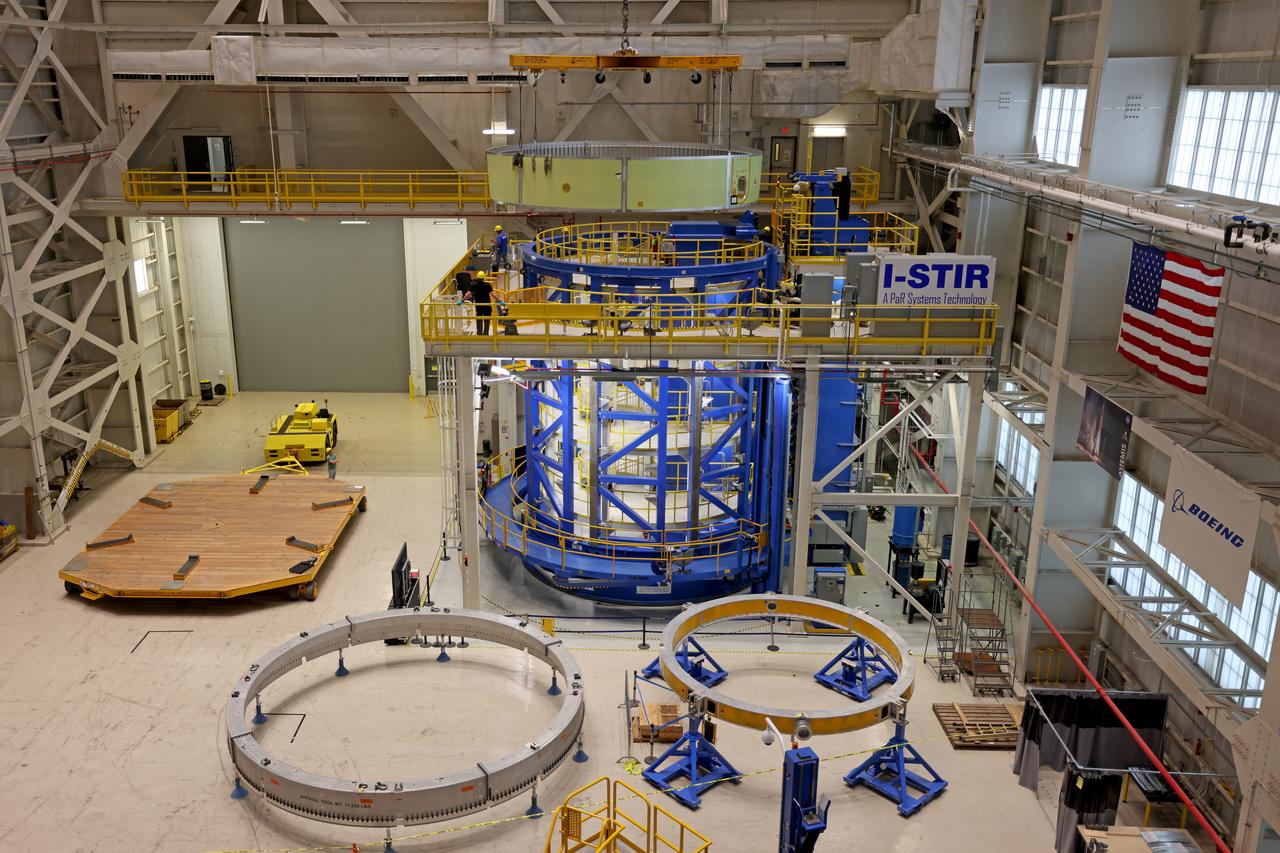
These images and videos show technicians at NASA’s Michoud Assembly Facility in New Orleans examining and lifting midbody barrels for the Exploration Upper Stage (EUS) structural test article of the SLS (Space Launch System) rocket in May 2023. The barrel sections make up the body, or main structure, of the future in-space propulsion stage for the mega rocket. The Exploration Upper Stage will be used on the second configuration of the SLS rocket, known as Block 1B, and will provide in-space propulsion to send astronauts in NASA’s Orion spacecraft and heavy cargo on a precise trajectory to the Moon. Beginning with Artemis IV, EUS will replace the interim cryogenic propulsion stage for the Block 1 configuration of SLS. It has larger propellant tanks and four RL10 engines, enabling SLS to launch 40% more cargo to the Moon along with crew. EUS flight hardware is in early production at Michoud. Crews with NASA and Boeing, the lead contractor for the SLS core stage and EUS, are also manufacturing the EUS structural test article. The test hardware is structurally identical to the flight version and will be used during a series of strenuous testing that simulates the forces the rocket will experience during launch and flight and verify its structural integrity. NASA is working to land the first woman and first person of color on the Moon under Artemis. SLS is part of NASA’s backbone for deep space exploration, along with Orion and the Gateway in orbit around the Moon. SLS is the only rocket that can send Orion, astronauts, and supplies to the Moon in a single mission.
These images and videos show technicians at NASA’s Michoud Assembly Facility in New Orleans examining and lifting midbody barrels for the Exploration Upper Stage (EUS) structural test article of the SLS (Space Launch System) rocket in May 2023. The barrel sections make up the body, or main structure, of the future in-space propulsion stage for the mega rocket. The Exploration Upper Stage will be used on the second configuration of the SLS rocket, known as Block 1B, and will provide in-space propulsion to send astronauts in NASA’s Orion spacecraft and heavy cargo on a precise trajectory to the Moon. Beginning with Artemis IV, EUS will replace the interim cryogenic propulsion stage for the Block 1 configuration of SLS. It has larger propellant tanks and four RL10 engines, enabling SLS to launch 40% more cargo to the Moon along with crew. EUS flight hardware is in early production at Michoud. Crews with NASA and Boeing, the lead contractor for the SLS core stage and EUS, are also manufacturing the EUS structural test article. The test hardware is structurally identical to the flight version and will be used during a series of strenuous testing that simulates the forces the rocket will experience during launch and flight and verify its structural integrity. NASA is working to land the first woman and first person of color on the Moon under Artemis. SLS is part of NASA’s backbone for deep space exploration, along with Orion and the Gateway in orbit around the Moon. SLS is the only rocket that can send Orion, astronauts, and supplies to the Moon in a single mission.
These images and videos show technicians at NASA’s Michoud Assembly Facility in New Orleans examining and lifting midbody barrels for the Exploration Upper Stage (EUS) structural test article of the SLS (Space Launch System) rocket in May 2023. The barrel sections make up the body, or main structure, of the future in-space propulsion stage for the mega rocket. The Exploration Upper Stage will be used on the second configuration of the SLS rocket, known as Block 1B, and will provide in-space propulsion to send astronauts in NASA’s Orion spacecraft and heavy cargo on a precise trajectory to the Moon. Beginning with Artemis IV, EUS will replace the interim cryogenic propulsion stage for the Block 1 configuration of SLS. It has larger propellant tanks and four RL10 engines, enabling SLS to launch 40% more cargo to the Moon along with crew. EUS flight hardware is in early production at Michoud. Crews with NASA and Boeing, the lead contractor for the SLS core stage and EUS, are also manufacturing the EUS structural test article. The test hardware is structurally identical to the flight version and will be used during a series of strenuous testing that simulates the forces the rocket will experience during launch and flight and verify its structural integrity. NASA is working to land the first woman and first person of color on the Moon under Artemis. SLS is part of NASA’s backbone for deep space exploration, along with Orion and the Gateway in orbit around the Moon. SLS is the only rocket that can send Orion, astronauts, and supplies to the Moon in a single mission.
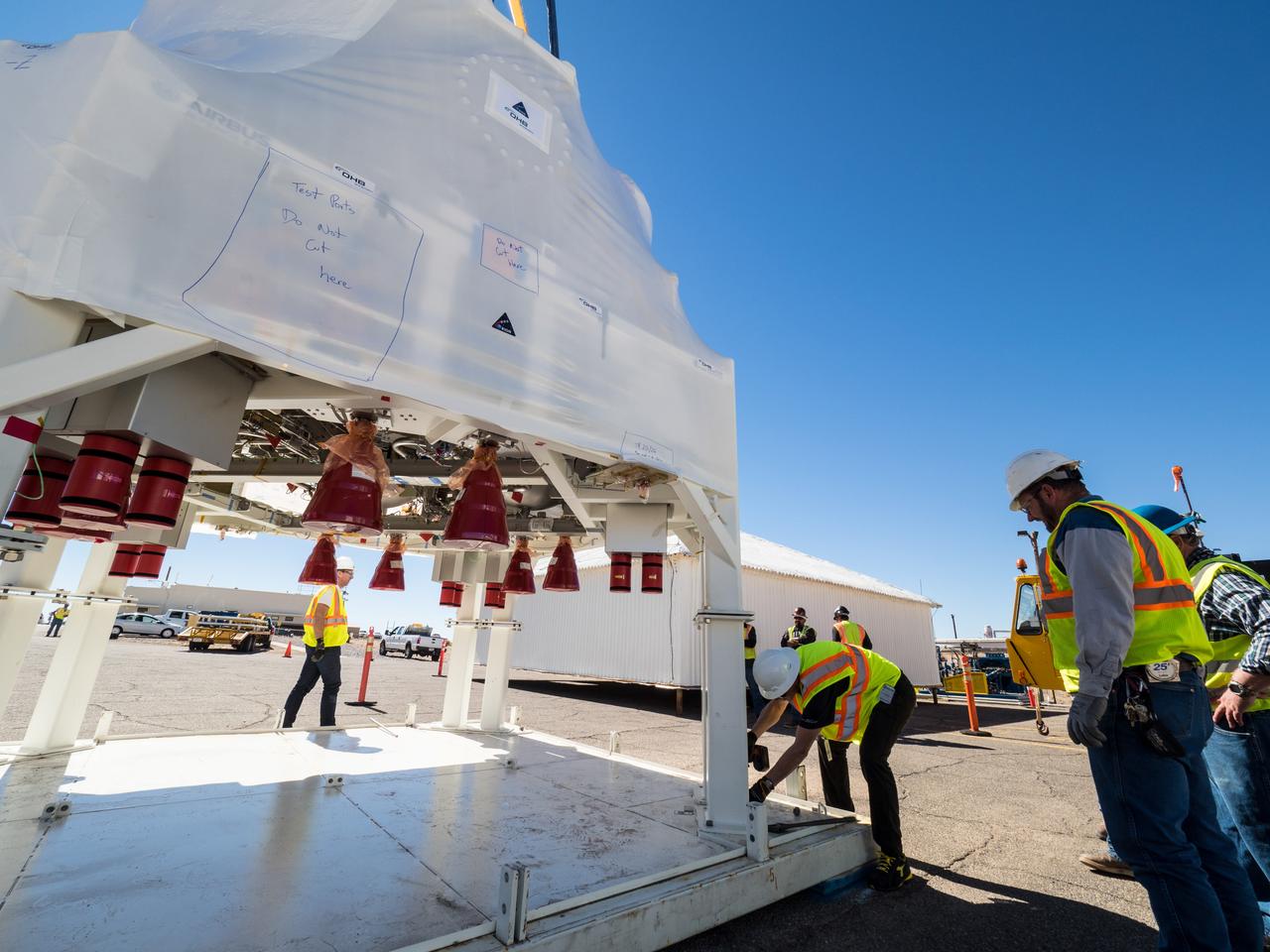
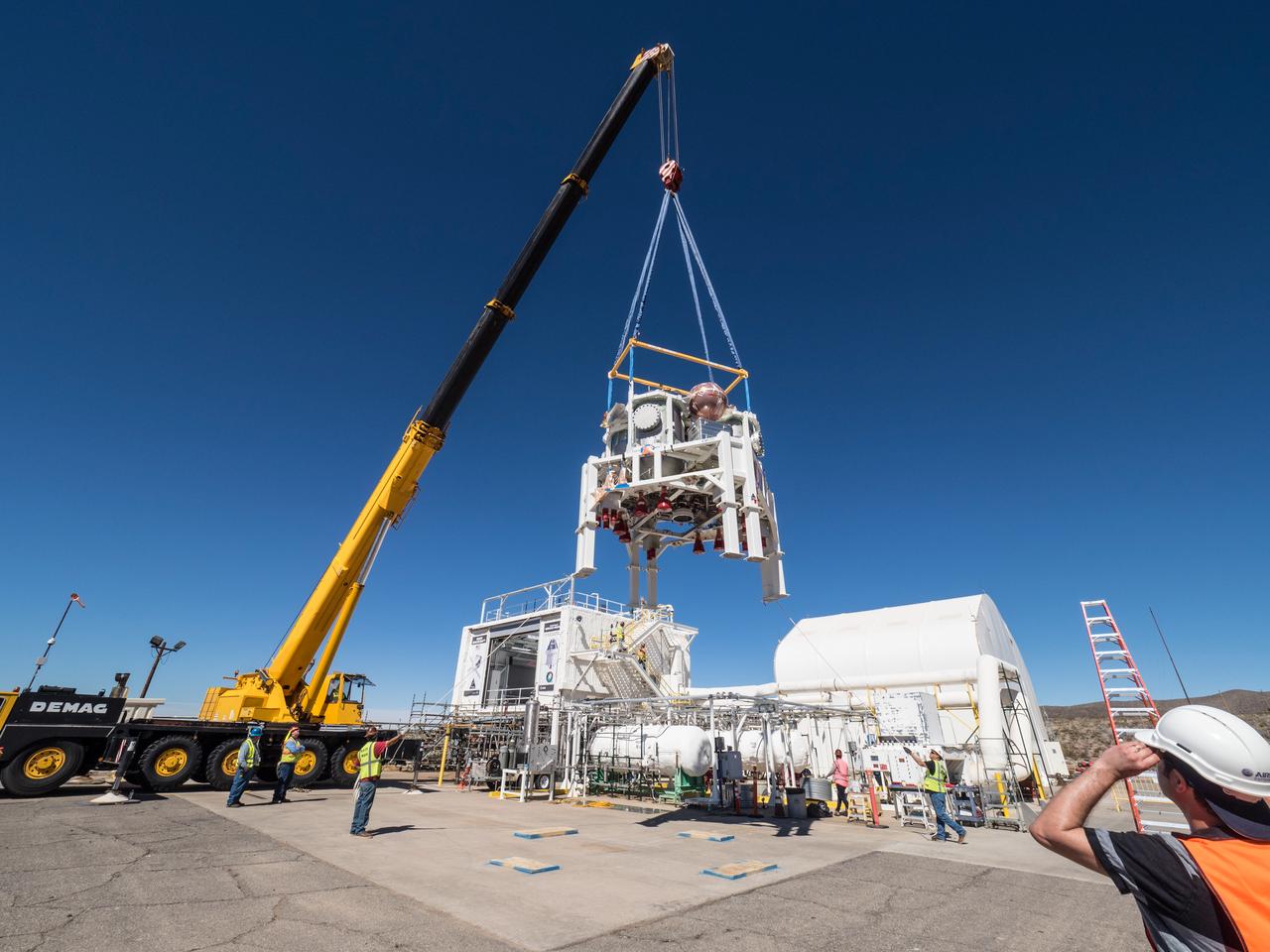
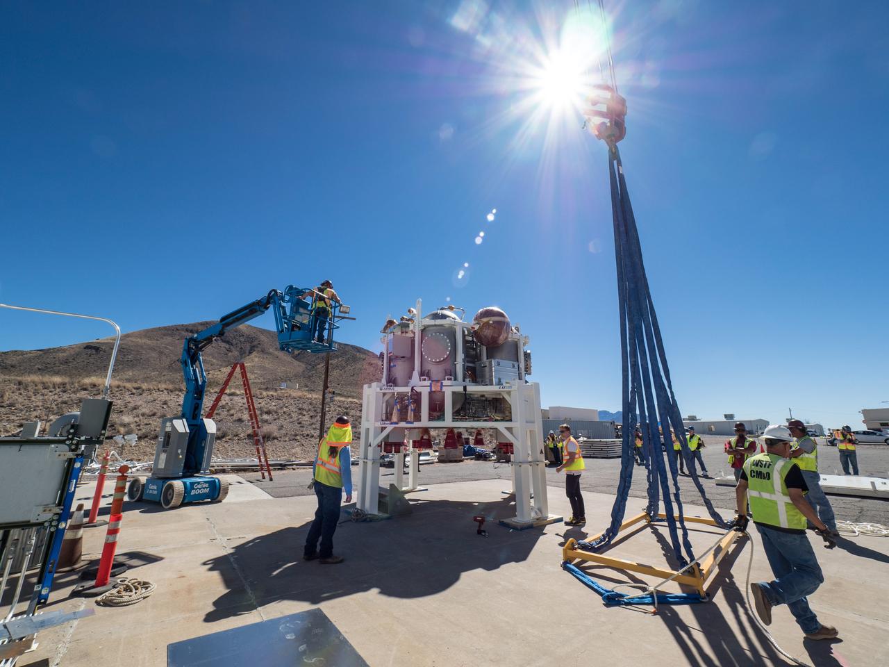
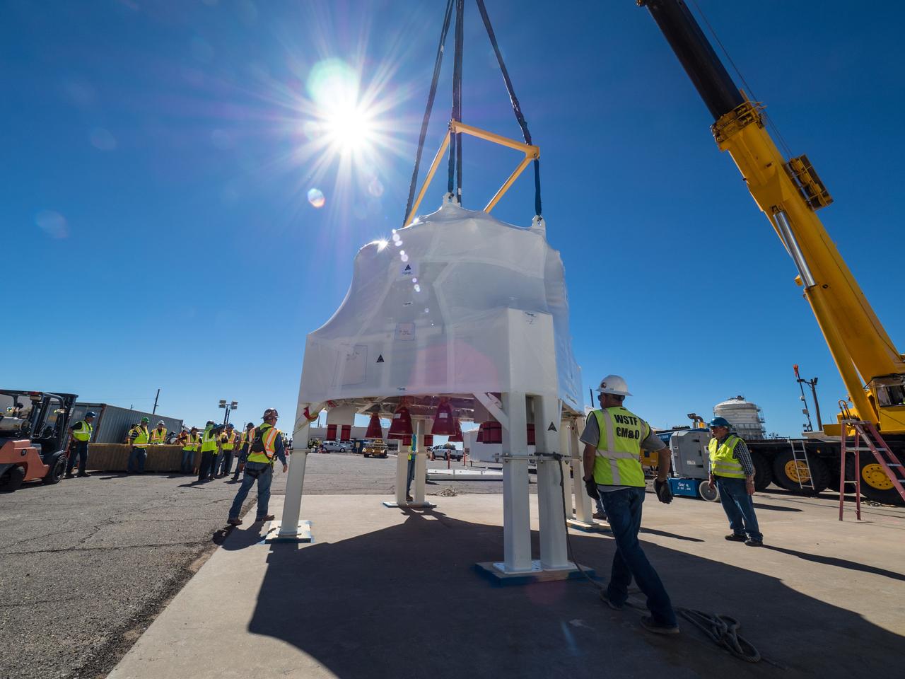
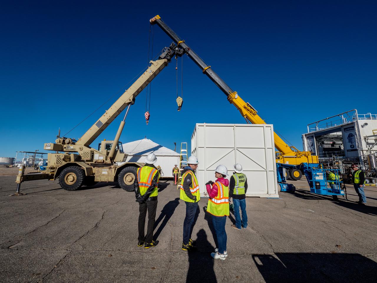
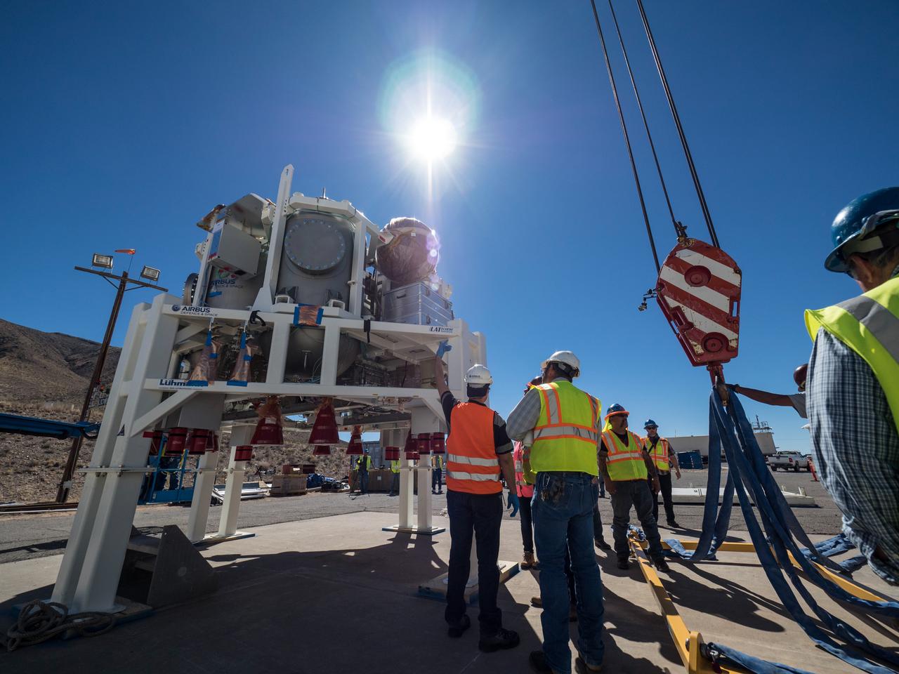
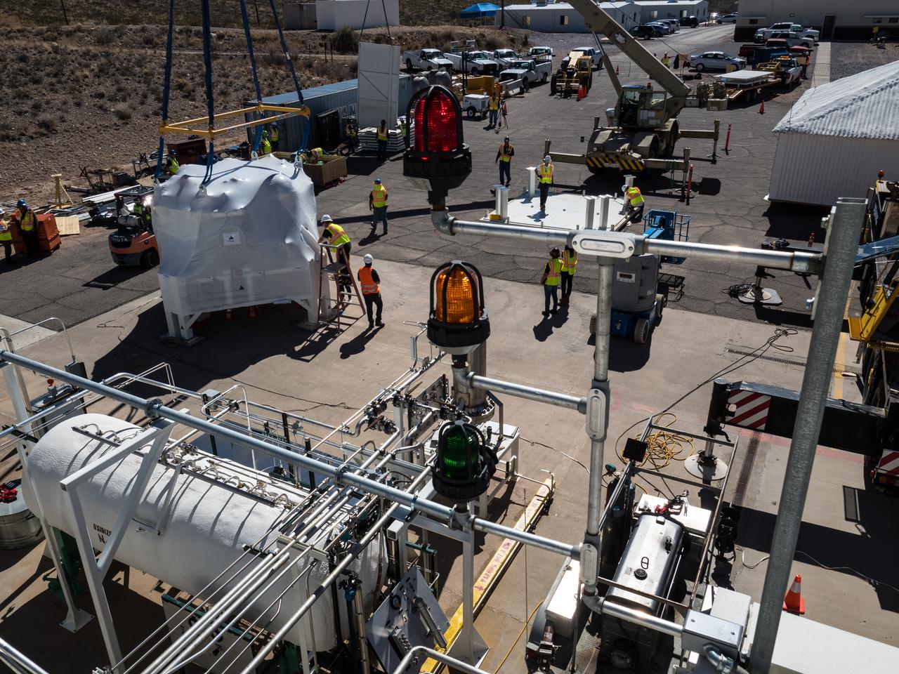
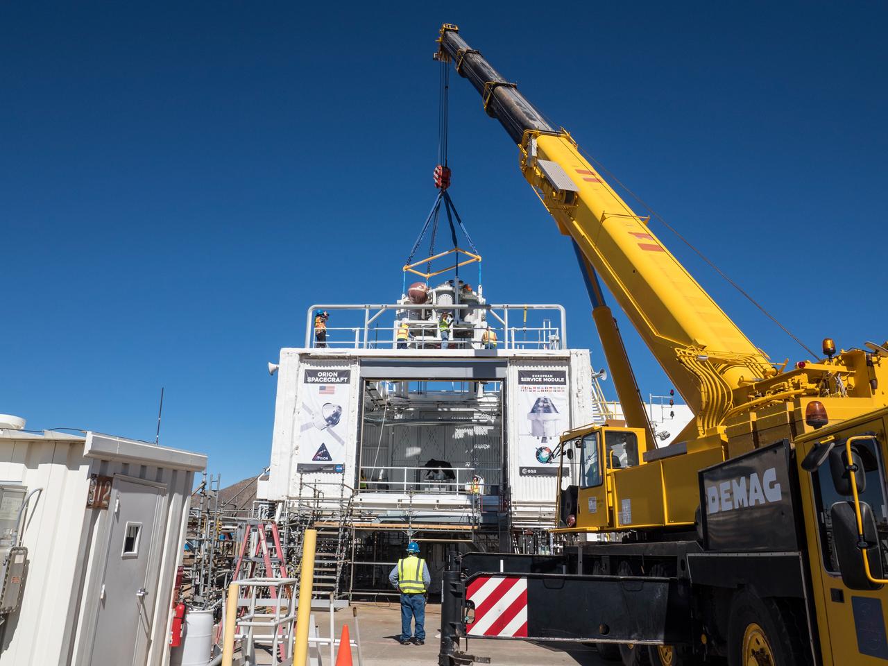
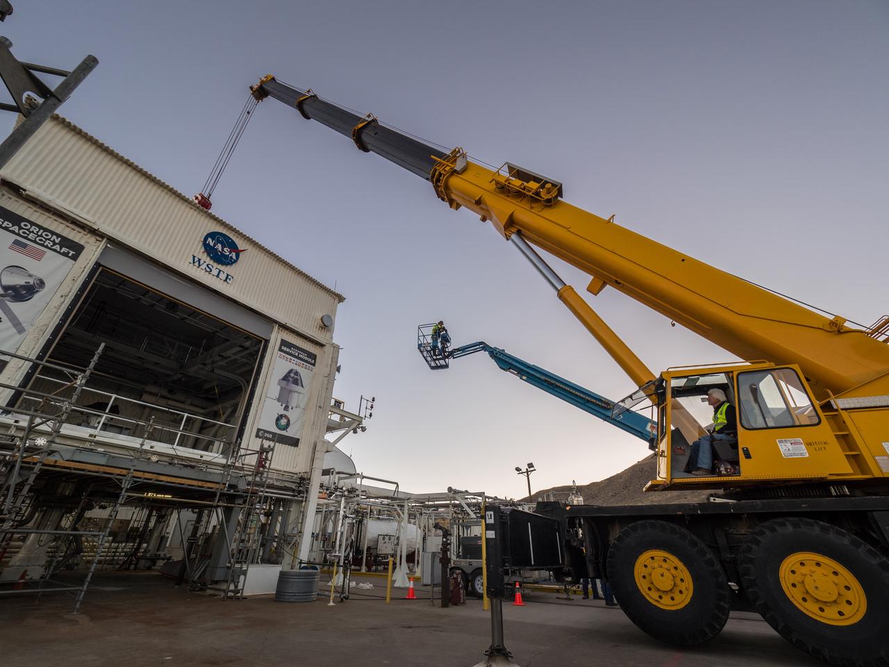
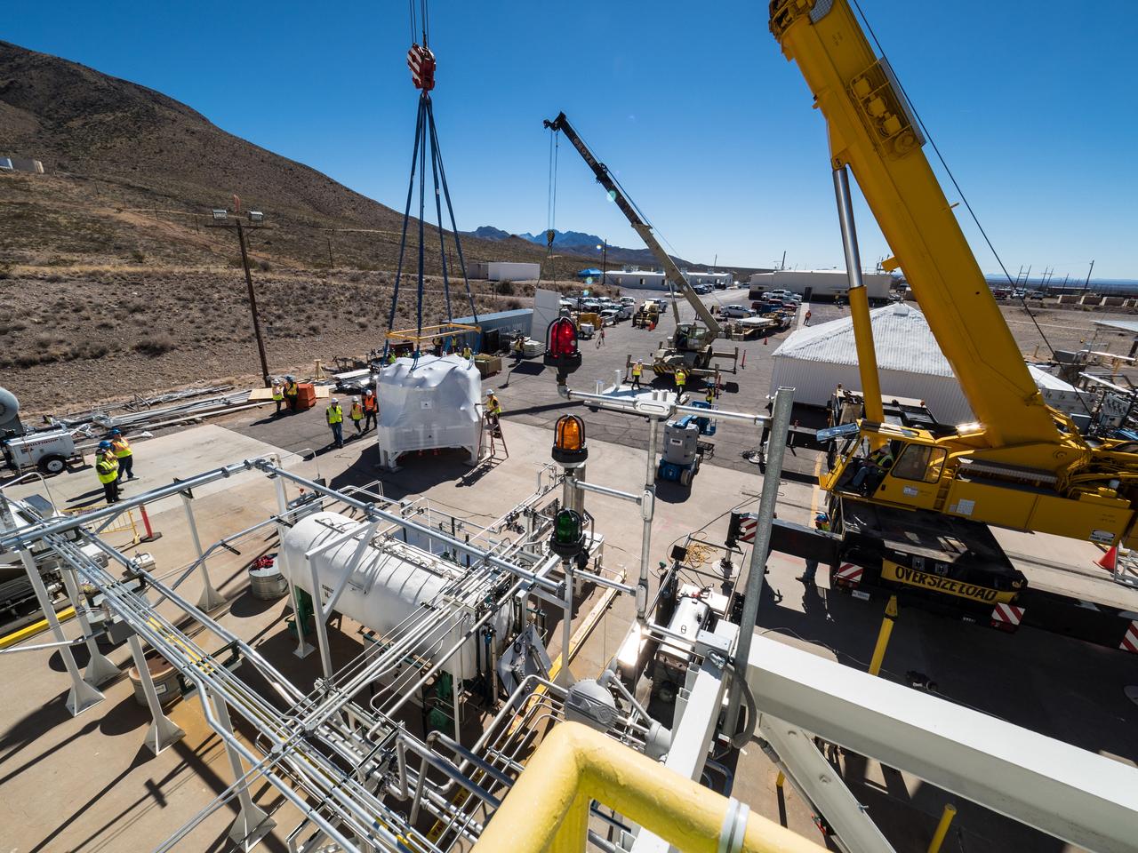
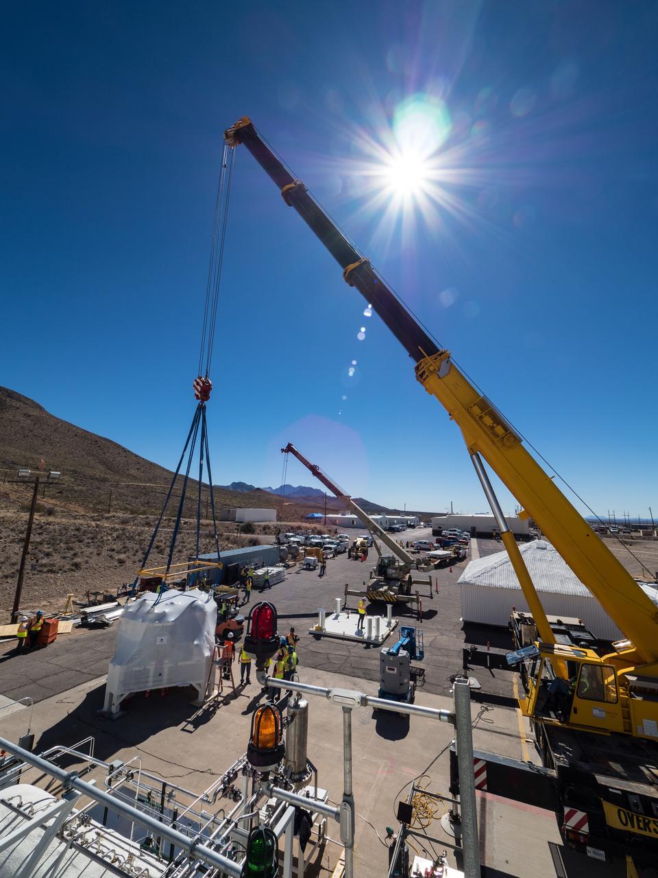
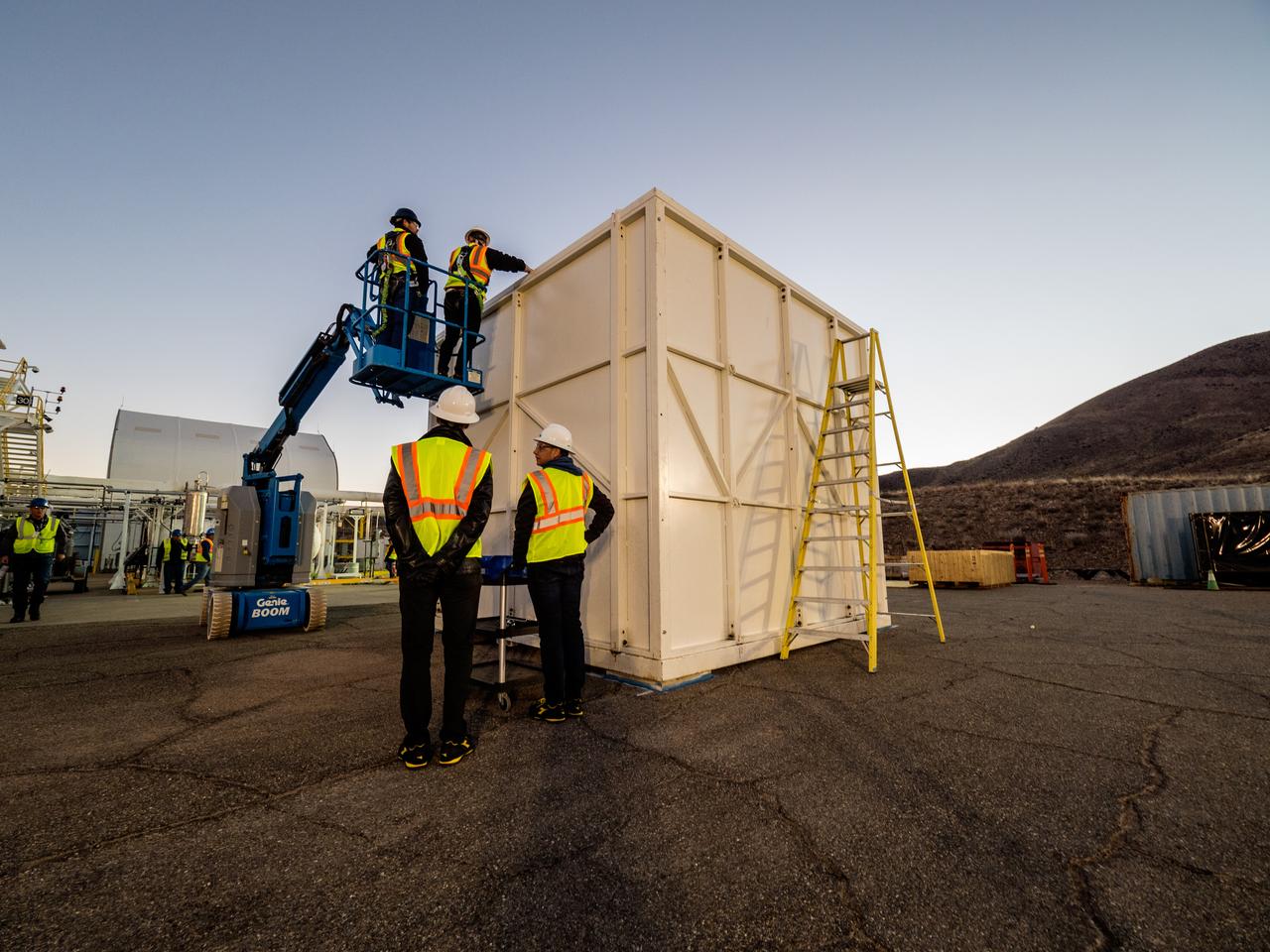
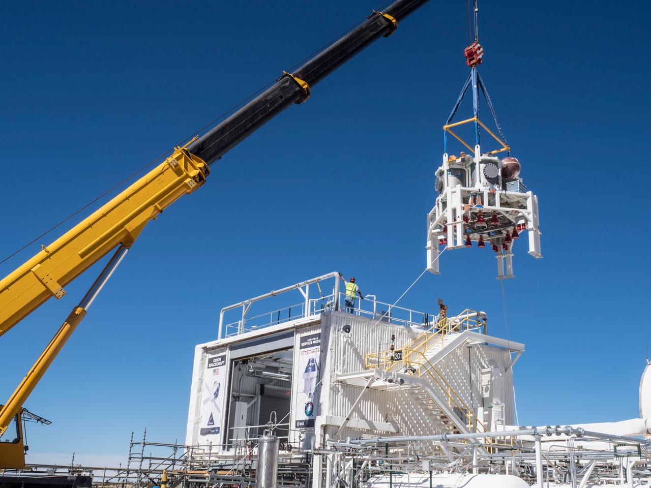
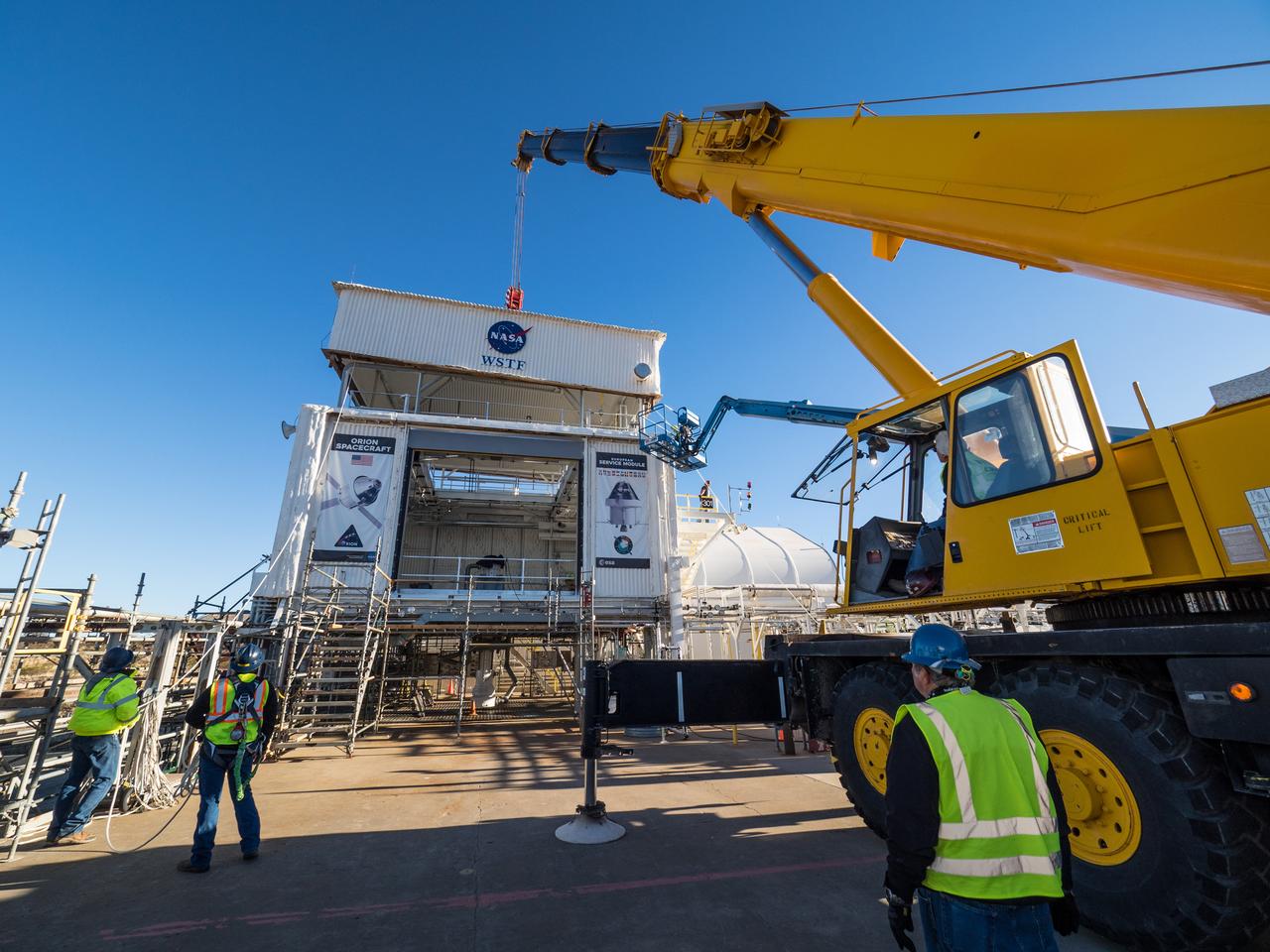
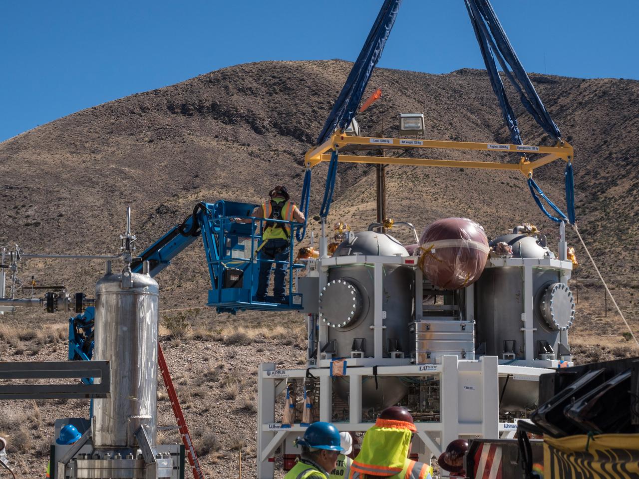
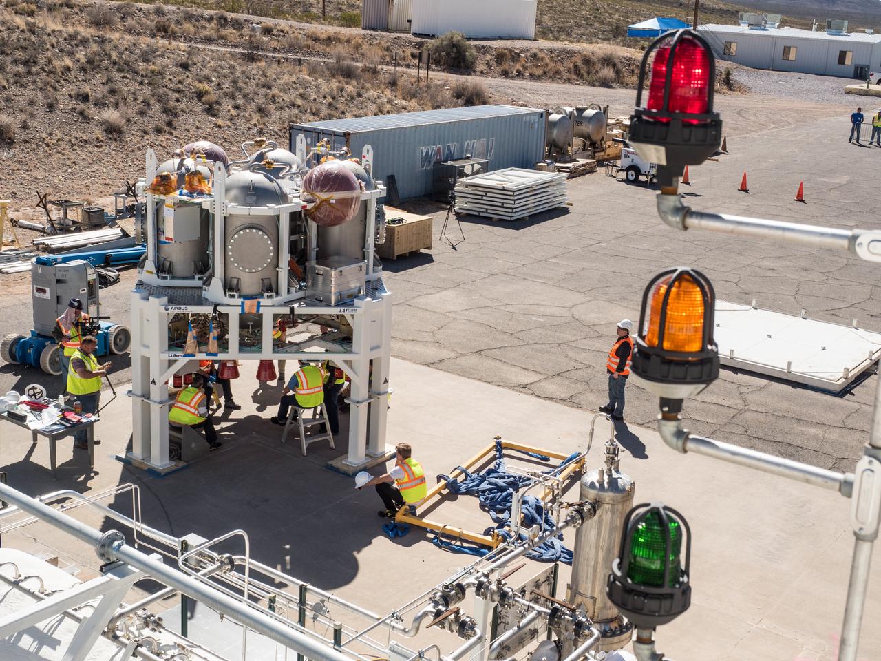
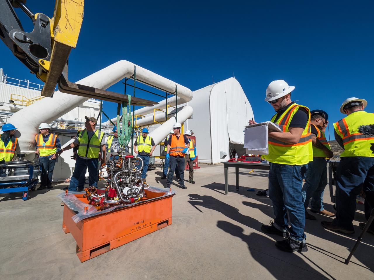
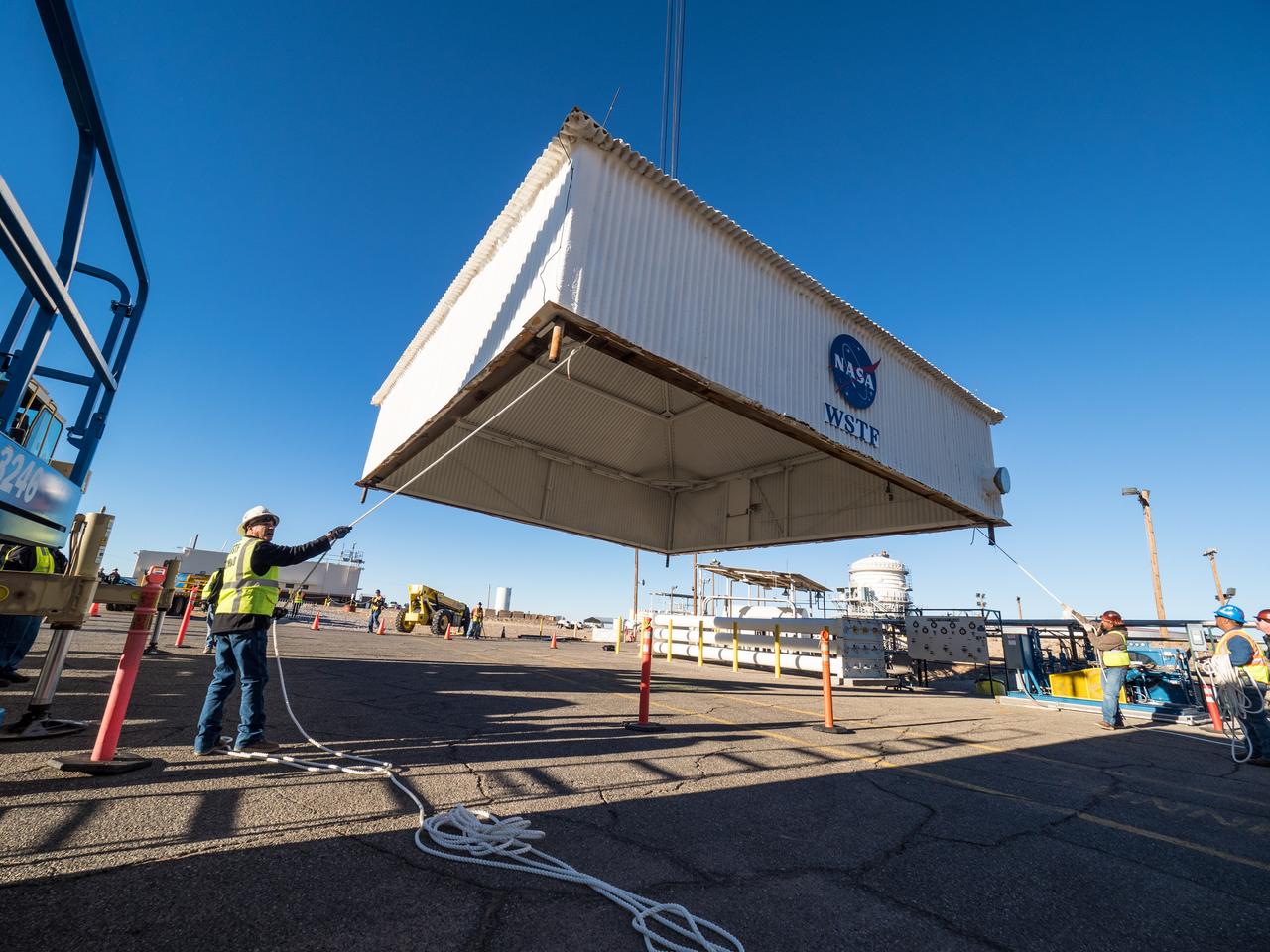
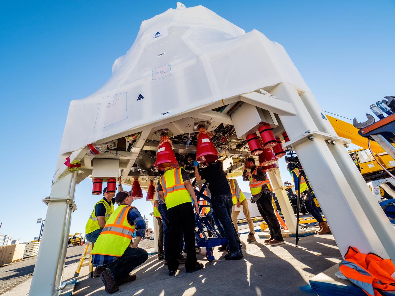
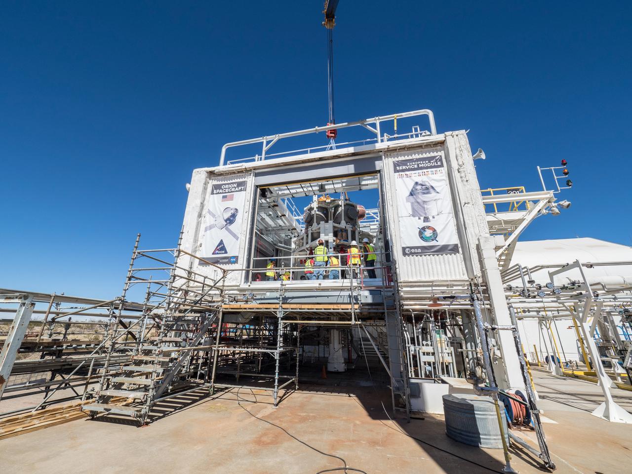
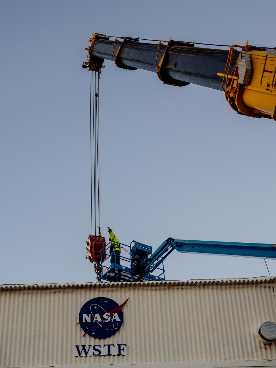
On Feb. 21, 2017 engineers successfully install ESA’s European Service Module Propulsion Qualification Module (PQM) at NASA’s White Sands Test Facility in New Mexico that was delivered by Airbus – ESA’s prime contractor for the Service Module. The module will be equipped with a total of 21 engines to support NASA’s Orion spacecraft: one U.S. Space Shuttle Orbital Maneuvering System (OMS) engine, eight auxiliary thrusters and 12 smaller thrusters produced by Airbus Safran Launchers in Germany. The all-steel PQM structure is used to test the propulsion systems on Orion, including “hot firing” of the OMS engine and thrusters.
On Feb. 22, engineers successfully install ESA’s European Service Module Propulsion Qualification Module (PQM) at NASA’s White Sands Test Facility in New Mexico that was delivered by Airbus – ESA’s prime contractor for the Service Module. The module will be equipped with a total of 21 engines to support NASA’s Orion spacecraft: one U.S. Space Shuttle Orbital Maneuvering System (OMS) engine, eight auxiliary thrusters and 12 smaller thrusters produced by Airbus Safran Launchers in Germany. The all-steel PQM structure is used to test the propulsion systems on Orion, including “hot firing” of the OMS engine and thrusters.
On Feb. 22, engineers successfully install ESA’s European Service Module Propulsion Qualification Module (PQM) at NASA’s White Sands Test Facility in New Mexico that was delivered by Airbus – ESA’s prime contractor for the Service Module. The module will be equipped with a total of 21 engines to support NASA’s Orion spacecraft: one U.S. Space Shuttle Orbital Maneuvering System (OMS) engine, eight auxiliary thrusters and 12 smaller thrusters produced by Airbus Safran Launchers in Germany. The all-steel PQM structure is used to test the propulsion systems on Orion, including “hot firing” of the OMS engine and thrusters.
On Feb. 21, 2017 engineers successfully install ESA’s European Service Module Propulsion Qualification Module (PQM) at NASA’s White Sands Test Facility in New Mexico that was delivered by Airbus – ESA’s prime contractor for the Service Module. The module will be equipped with a total of 21 engines to support NASA’s Orion spacecraft: one U.S. Space Shuttle Orbital Maneuvering System (OMS) engine, eight auxiliary thrusters and 12 smaller thrusters produced by Airbus Safran Launchers in Germany. The all-steel PQM structure is used to test the propulsion systems on Orion, including “hot firing” of the OMS engine and thrusters.
On Feb. 21, 2017 engineers successfully install ESA’s European Service Module Propulsion Qualification Module (PQM) at NASA’s White Sands Test Facility in New Mexico that was delivered by Airbus – ESA’s prime contractor for the Service Module. The module will be equipped with a total of 21 engines to support NASA’s Orion spacecraft: one U.S. Space Shuttle Orbital Maneuvering System (OMS) engine, eight auxiliary thrusters and 12 smaller thrusters produced by Airbus Safran Launchers in Germany. The all-steel PQM structure is used to test the propulsion systems on Orion, including “hot firing” of the OMS engine and thrusters.
On Feb. 22, engineers successfully install ESA’s European Service Module Propulsion Qualification Module (PQM) at NASA’s White Sands Test Facility in New Mexico that was delivered by Airbus – ESA’s prime contractor for the Service Module. The module will be equipped with a total of 21 engines to support NASA’s Orion spacecraft: one U.S. Space Shuttle Orbital Maneuvering System (OMS) engine, eight auxiliary thrusters and 12 smaller thrusters produced by Airbus Safran Launchers in Germany. The all-steel PQM structure is used to test the propulsion systems on Orion, including “hot firing” of the OMS engine and thrusters.
On Feb. 21, 2017 engineers successfully install ESA’s European Service Module Propulsion Qualification Module (PQM) at NASA’s White Sands Test Facility in New Mexico that was delivered by Airbus – ESA’s prime contractor for the Service Module. The module will be equipped with a total of 21 engines to support NASA’s Orion spacecraft: one U.S. Space Shuttle Orbital Maneuvering System (OMS) engine, eight auxiliary thrusters and 12 smaller thrusters produced by Airbus Safran Launchers in Germany. The all-steel PQM structure is used to test the propulsion systems on Orion, including “hot firing” of the OMS engine and thrusters.

On Feb. 21, 2017 engineers successfully install ESA’s European Service Module Propulsion Qualification Module (PQM) at NASA’s White Sands Test Facility in New Mexico that was delivered by Airbus – ESA’s prime contractor for the Service Module. The module will be equipped with a total of 21 engines to support NASA’s Orion spacecraft: one U.S. Space Shuttle Orbital Maneuvering System (OMS) engine, eight auxiliary thrusters and 12 smaller thrusters produced by Airbus Safran Launchers in Germany. The all-steel PQM structure is used to test the propulsion systems on Orion, including “hot firing” of the OMS engine and thrusters.

On Feb. 22, engineers successfully install ESA’s European Service Module Propulsion Qualification Module (PQM) at NASA’s White Sands Test Facility in New Mexico that was delivered by Airbus – ESA’s prime contractor for the Service Module. The module will be equipped with a total of 21 engines to support NASA’s Orion spacecraft: one U.S. Space Shuttle Orbital Maneuvering System (OMS) engine, eight auxiliary thrusters and 12 smaller thrusters produced by Airbus Safran Launchers in Germany. The all-steel PQM structure is used to test the propulsion systems on Orion, including “hot firing” of the OMS engine and thrusters.
On Feb. 21, 2017 engineers successfully install ESA’s European Service Module Propulsion Qualification Module (PQM) at NASA’s White Sands Test Facility in New Mexico that was delivered by Airbus – ESA’s prime contractor for the Service Module. The module will be equipped with a total of 21 engines to support NASA’s Orion spacecraft: one U.S. Space Shuttle Orbital Maneuvering System (OMS) engine, eight auxiliary thrusters and 12 smaller thrusters produced by Airbus Safran Launchers in Germany. The all-steel PQM structure is used to test the propulsion systems on Orion, including “hot firing” of the OMS engine and thrusters.
On Feb. 21, 2017 engineers successfully install ESA’s European Service Module Propulsion Qualification Module (PQM) at NASA’s White Sands Test Facility in New Mexico that was delivered by Airbus – ESA’s prime contractor for the Service Module. The module will be equipped with a total of 21 engines to support NASA’s Orion spacecraft: one U.S. Space Shuttle Orbital Maneuvering System (OMS) engine, eight auxiliary thrusters and 12 smaller thrusters produced by Airbus Safran Launchers in Germany. The all-steel PQM structure is used to test the propulsion systems on Orion, including “hot firing” of the OMS engine and thrusters.
On Feb. 21, 2017 engineers successfully install ESA’s European Service Module Propulsion Qualification Module (PQM) at NASA’s White Sands Test Facility in New Mexico that was delivered by Airbus – ESA’s prime contractor for the Service Module. The module will be equipped with a total of 21 engines to support NASA’s Orion spacecraft: one U.S. Space Shuttle Orbital Maneuvering System (OMS) engine, eight auxiliary thrusters and 12 smaller thrusters produced by Airbus Safran Launchers in Germany. The all-steel PQM structure is used to test the propulsion systems on Orion, including “hot firing” of the OMS engine and thrusters.

On Feb. 21, 2017 engineers successfully install ESA’s European Service Module Propulsion Qualification Module (PQM) at NASA’s White Sands Test Facility in New Mexico that was delivered by Airbus – ESA’s prime contractor for the Service Module. The module will be equipped with a total of 21 engines to support NASA’s Orion spacecraft: one U.S. Space Shuttle Orbital Maneuvering System (OMS) engine, eight auxiliary thrusters and 12 smaller thrusters produced by Airbus Safran Launchers in Germany. The all-steel PQM structure is used to test the propulsion systems on Orion, including “hot firing” of the OMS engine and thrusters.
On Feb. 22, engineers successfully install ESA’s European Service Module Propulsion Qualification Module (PQM) at NASA’s White Sands Test Facility in New Mexico that was delivered by Airbus – ESA’s prime contractor for the Service Module. The module will be equipped with a total of 21 engines to support NASA’s Orion spacecraft: one U.S. Space Shuttle Orbital Maneuvering System (OMS) engine, eight auxiliary thrusters and 12 smaller thrusters produced by Airbus Safran Launchers in Germany. The all-steel PQM structure is used to test the propulsion systems on Orion, including “hot firing” of the OMS engine and thrusters.
On Feb. 21, 2017 engineers successfully install ESA’s European Service Module Propulsion Qualification Module (PQM) at NASA’s White Sands Test Facility in New Mexico that was delivered by Airbus – ESA’s prime contractor for the Service Module. The module will be equipped with a total of 21 engines to support NASA’s Orion spacecraft: one U.S. Space Shuttle Orbital Maneuvering System (OMS) engine, eight auxiliary thrusters and 12 smaller thrusters produced by Airbus Safran Launchers in Germany. The all-steel PQM structure is used to test the propulsion systems on Orion, including “hot firing” of the OMS engine and thrusters.
On Feb. 22, engineers successfully install ESA’s European Service Module Propulsion Qualification Module (PQM) at NASA’s White Sands Test Facility in New Mexico that was delivered by Airbus – ESA’s prime contractor for the Service Module. The module will be equipped with a total of 21 engines to support NASA’s Orion spacecraft: one U.S. Space Shuttle Orbital Maneuvering System (OMS) engine, eight auxiliary thrusters and 12 smaller thrusters produced by Airbus Safran Launchers in Germany. The all-steel PQM structure is used to test the propulsion systems on Orion, including “hot firing” of the OMS engine and thrusters.

On Feb. 22, engineers successfully install ESA’s European Service Module Propulsion Qualification Module (PQM) at NASA’s White Sands Test Facility in New Mexico that was delivered by Airbus – ESA’s prime contractor for the Service Module. The module will be equipped with a total of 21 engines to support NASA’s Orion spacecraft: one U.S. Space Shuttle Orbital Maneuvering System (OMS) engine, eight auxiliary thrusters and 12 smaller thrusters produced by Airbus Safran Launchers in Germany. The all-steel PQM structure is used to test the propulsion systems on Orion, including “hot firing” of the OMS engine and thrusters.
On Feb. 22, engineers successfully install ESA’s European Service Module Propulsion Qualification Module (PQM) at NASA’s White Sands Test Facility in New Mexico that was delivered by Airbus – ESA’s prime contractor for the Service Module. The module will be equipped with a total of 21 engines to support NASA’s Orion spacecraft: one U.S. Space Shuttle Orbital Maneuvering System (OMS) engine, eight auxiliary thrusters and 12 smaller thrusters produced by Airbus Safran Launchers in Germany. The all-steel PQM structure is used to test the propulsion systems on Orion, including “hot firing” of the OMS engine and thrusters.
On Feb. 21, 2017 engineers successfully install ESA’s European Service Module Propulsion Qualification Module (PQM) at NASA’s White Sands Test Facility in New Mexico that was delivered by Airbus – ESA’s prime contractor for the Service Module. The module will be equipped with a total of 21 engines to support NASA’s Orion spacecraft: one U.S. Space Shuttle Orbital Maneuvering System (OMS) engine, eight auxiliary thrusters and 12 smaller thrusters produced by Airbus Safran Launchers in Germany. The all-steel PQM structure is used to test the propulsion systems on Orion, including “hot firing” of the OMS engine and thrusters.
On Feb. 21, 2017 engineers successfully install ESA’s European Service Module Propulsion Qualification Module (PQM) at NASA’s White Sands Test Facility in New Mexico that was delivered by Airbus – ESA’s prime contractor for the Service Module. The module will be equipped with a total of 21 engines to support NASA’s Orion spacecraft: one U.S. Space Shuttle Orbital Maneuvering System (OMS) engine, eight auxiliary thrusters and 12 smaller thrusters produced by Airbus Safran Launchers in Germany. The all-steel PQM structure is used to test the propulsion systems on Orion, including “hot firing” of the OMS engine and thrusters.
On Feb. 21, 2017 engineers successfully install ESA’s European Service Module Propulsion Qualification Module (PQM) at NASA’s White Sands Test Facility in New Mexico that was delivered by Airbus – ESA’s prime contractor for the Service Module. The module will be equipped with a total of 21 engines to support NASA’s Orion spacecraft: one U.S. Space Shuttle Orbital Maneuvering System (OMS) engine, eight auxiliary thrusters and 12 smaller thrusters produced by Airbus Safran Launchers in Germany. The all-steel PQM structure is used to test the propulsion systems on Orion, including “hot firing” of the OMS engine and thrusters.

On Feb. 21, 2017 engineers successfully install ESA’s European Service Module Propulsion Qualification Module (PQM) at NASA’s White Sands Test Facility in New Mexico that was delivered by Airbus – ESA’s prime contractor for the Service Module. The module will be equipped with a total of 21 engines to support NASA’s Orion spacecraft: one U.S. Space Shuttle Orbital Maneuvering System (OMS) engine, eight auxiliary thrusters and 12 smaller thrusters produced by Airbus Safran Launchers in Germany. The all-steel PQM structure is used to test the propulsion systems on Orion, including “hot firing” of the OMS engine and thrusters.
On Feb. 22, engineers successfully install ESA’s European Service Module Propulsion Qualification Module (PQM) at NASA’s White Sands Test Facility in New Mexico that was delivered by Airbus – ESA’s prime contractor for the Service Module. The module will be equipped with a total of 21 engines to support NASA’s Orion spacecraft: one U.S. Space Shuttle Orbital Maneuvering System (OMS) engine, eight auxiliary thrusters and 12 smaller thrusters produced by Airbus Safran Launchers in Germany. The all-steel PQM structure is used to test the propulsion systems on Orion, including “hot firing” of the OMS engine and thrusters.

On Feb. 21, 2017 engineers successfully install ESA’s European Service Module Propulsion Qualification Module (PQM) at NASA’s White Sands Test Facility in New Mexico that was delivered by Airbus – ESA’s prime contractor for the Service Module. The module will be equipped with a total of 21 engines to support NASA’s Orion spacecraft: one U.S. Space Shuttle Orbital Maneuvering System (OMS) engine, eight auxiliary thrusters and 12 smaller thrusters produced by Airbus Safran Launchers in Germany. The all-steel PQM structure is used to test the propulsion systems on Orion, including “hot firing” of the OMS engine and thrusters.
On Feb. 21, 2017 engineers successfully install ESA’s European Service Module Propulsion Qualification Module (PQM) at NASA’s White Sands Test Facility in New Mexico that was delivered by Airbus – ESA’s prime contractor for the Service Module. The module will be equipped with a total of 21 engines to support NASA’s Orion spacecraft: one U.S. Space Shuttle Orbital Maneuvering System (OMS) engine, eight auxiliary thrusters and 12 smaller thrusters produced by Airbus Safran Launchers in Germany. The all-steel PQM structure is used to test the propulsion systems on Orion, including “hot firing” of the OMS engine and thrusters.
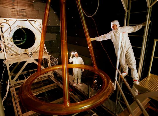
The Shooting Star Experiment (SSE) is designed to develop and demonstrate the technology required to focus the sun's energy and use the energy for inexpensive space Propulsion Research. Pictured is an engineering model (Pathfinder III) of the Shooting Star Experiment (SSE). This model was used to test and characterize the motion and deformation of the structure caused by thermal effects. In this photograph, alignment targets are being placed on the engineering model so that a theodolite (alignment telescope) could be used to accurately measure the deformation and deflections of the engineering model under extreme conditions, such as the coldness of deep space and the hotness of the sun as well as vacuum. This thermal vacuum test was performed at the X-Ray Calibration Facility because of the size of the test article and the capabilities of the facility to simulate in-orbit conditions
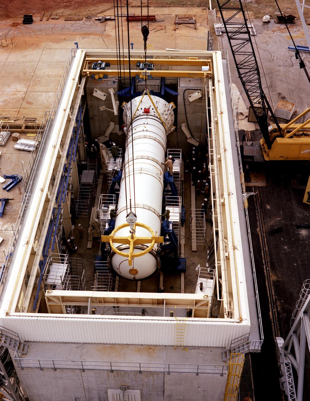
The solid rocket booster (SRB) structural test article is being installed in the Solid Rocket Booster Test Facility for the structural and load verification test at the Marshall Space Flight Center (MSFC). The Shuttle's two SRB's are the largest solids ever built and the first designed for refurbishment and reuse. Standing nearly 150-feet high, the twin boosters provide the majority of thrust for the first two minutes of flight, about 5.8 million pounds, augmenting the Shuttle's main propulsion system during liftoff. The major design drivers for the solid rocket motors (SRM's) were high thrust and reuse. The desired thrust was achieved by using state-of-the-art solid propellant and by using a long cylindrical motor with a specific core design that allows the propellant to burn in a carefully controlled marner. At burnout, the boosters separate from the external tank and drop by parachute to the ocean for recovery and subsequent refurbishment.
Aerial view of the 8- by 6-Foot Supersonic Wind Tunnel in its original configuration at the National Advisory Committee for Aeronautics (NACA) Lewis Flight Propulsion Laboratory. The 8- by 6 was the laboratory’s first large supersonic wind tunnel. It was also the NACA’s most powerful supersonic tunnel, and its first facility capable of running an engine at supersonic speeds. The 8- by 6-foot tunnel has been used to study inlets and exit nozzles, fuel injectors, flameholders, exit nozzles, and controls on ramjet and turbojet propulsion systems. The 8- by 6 was originally an open-throat and non-return tunnel. This meant that the supersonic air flow was blown through the test section and out the other end into the atmosphere. In this photograph, the three drive motors in the structure at the left supplied power to the seven-stage axial-flow compressor in the light-colored structure. The air flow passed through flexible walls which were bent to create the desired speed. The test article was located in the 8- by 6-foot stainless steel test section located inside the steel pressure chamber at the center of this photograph. The tunnel dimensions were then gradually increased to slow the air flow before it exited into the atmosphere. The large two-story building in front of the tunnel was used as office space for the researchers.
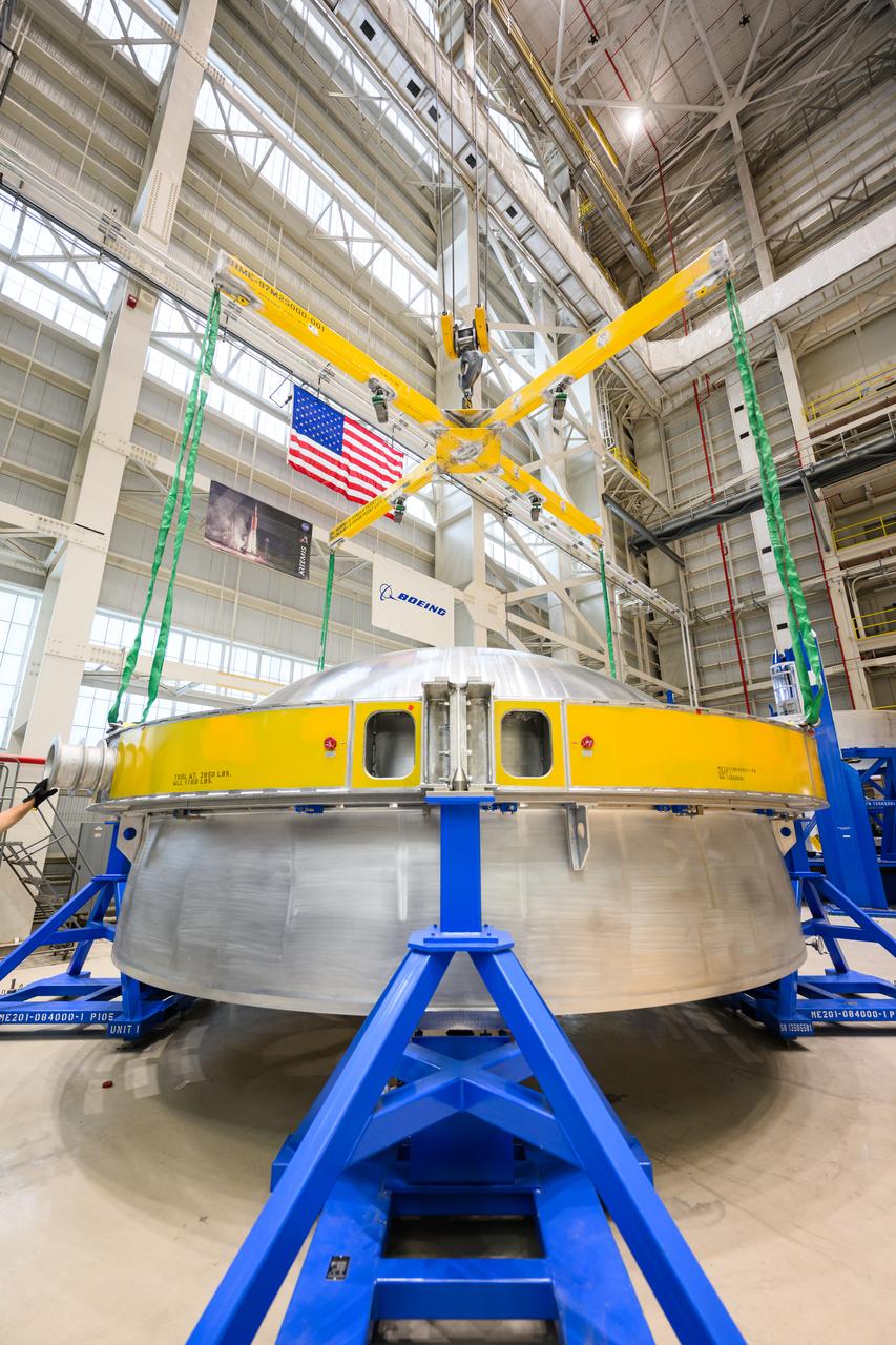
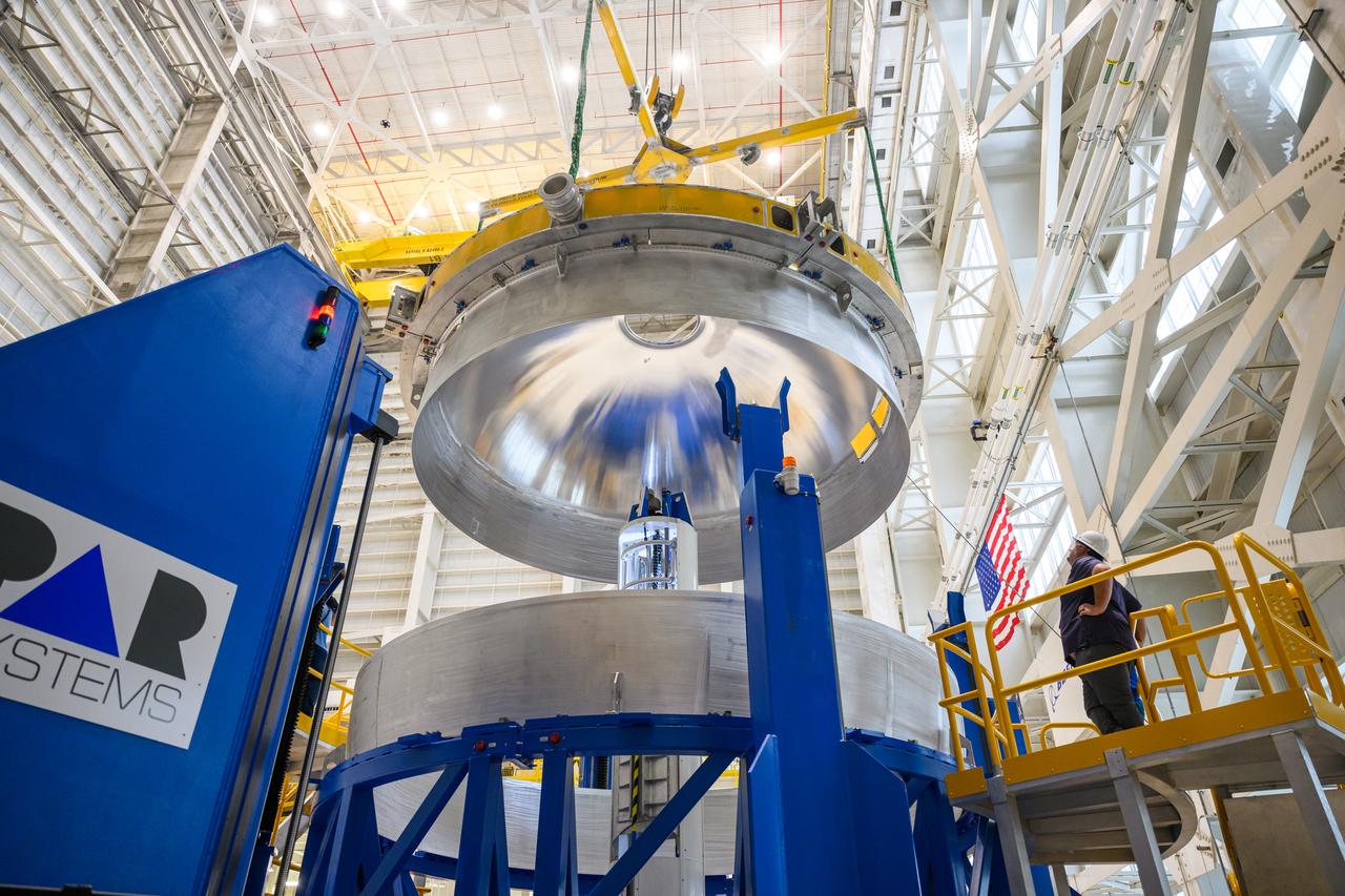
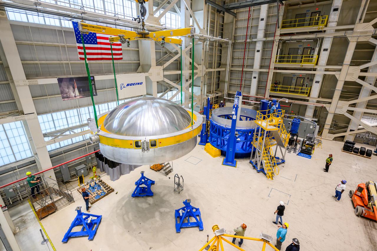
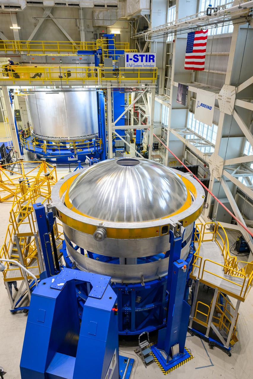
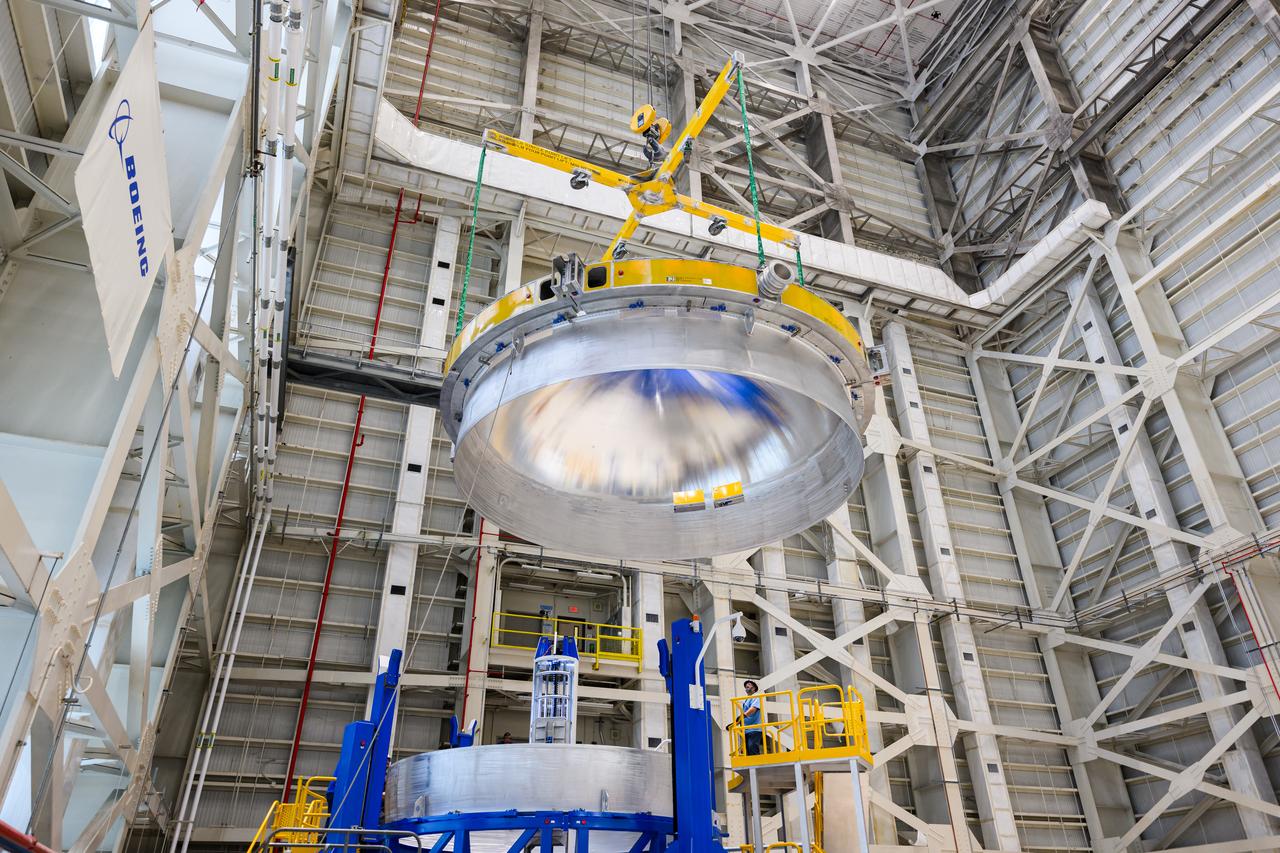
These images show technicians at NASA’s Michoud Assembly Facility in New Orleans lifting and installing the liquid oxygen dome weld confidence article for a future upper stage for NASA’s SLS (Space Launch System) rocket onto the LTAC (LOX Tank Assembly Center) in Building 115 at Michoud for the next phase of manufacturing in July 2023. The dome makes up a portion of the liquid oxygen tank weld confidence article for the EUS (exploration upper stage). Teams use weld confidence articles to verify welding procedures and structural integrity of the welds to manufacture structural test and flight versions of the hardware. EUS flight hardware is in early production at Michoud. The more powerful upper stage and its four RL10 engines will be used on the second configuration of the SLS rocket, known as Block 1B, and will provide in-space propulsion to send astronauts in NASA’s Orion spacecraft and heavy cargo on a precise trajectory to the Moon. NASA and Boeing, the lead contractor for the SLS core stage and EUS, are manufacturing SLS stages for Artemis II, III, IV, and V at the facility. NASA is working to land the first woman and first person of color on the Moon under Artemis. SLS is part of NASA’s backbone for deep space exploration, along with Orion and the Gateway in orbit around the Moon. SLS is the only rocket that can send Orion, astronauts, and supplies to the Moon in a single mission.
These images show technicians at NASA’s Michoud Assembly Facility in New Orleans lifting and installing the liquid oxygen dome weld confidence article for a future upper stage for NASA’s SLS (Space Launch System) rocket onto the LTAC (LOX Tank Assembly Center) in Building 115 at Michoud for the next phase of manufacturing in July 2023. The dome makes up a portion of the liquid oxygen tank weld confidence article for the EUS (exploration upper stage). Teams use weld confidence articles to verify welding procedures and structural integrity of the welds to manufacture structural test and flight versions of the hardware. EUS flight hardware is in early production at Michoud. The more powerful upper stage and its four RL10 engines will be used on the second configuration of the SLS rocket, known as Block 1B, and will provide in-space propulsion to send astronauts in NASA’s Orion spacecraft and heavy cargo on a precise trajectory to the Moon. NASA and Boeing, the lead contractor for the SLS core stage and EUS, are manufacturing SLS stages for Artemis II, III, IV, and V at the facility. NASA is working to land the first woman and first person of color on the Moon under Artemis. SLS is part of NASA’s backbone for deep space exploration, along with Orion and the Gateway in orbit around the Moon. SLS is the only rocket that can send Orion, astronauts, and supplies to the Moon in a single mission.

These images show technicians at NASA’s Michoud Assembly Facility in New Orleans lifting and installing the liquid oxygen dome weld confidence article for a future upper stage for NASA’s SLS (Space Launch System) rocket onto the LTAC (LOX Tank Assembly Center) in Building 115 at Michoud for the next phase of manufacturing in July 2023. The dome makes up a portion of the liquid oxygen tank weld confidence article for the EUS (exploration upper stage). Teams use weld confidence articles to verify welding procedures and structural integrity of the welds to manufacture structural test and flight versions of the hardware. EUS flight hardware is in early production at Michoud. The more powerful upper stage and its four RL10 engines will be used on the second configuration of the SLS rocket, known as Block 1B, and will provide in-space propulsion to send astronauts in NASA’s Orion spacecraft and heavy cargo on a precise trajectory to the Moon. NASA and Boeing, the lead contractor for the SLS core stage and EUS, are manufacturing SLS stages for Artemis II, III, IV, and V at the facility. NASA is working to land the first woman and first person of color on the Moon under Artemis. SLS is part of NASA’s backbone for deep space exploration, along with Orion and the Gateway in orbit around the Moon. SLS is the only rocket that can send Orion, astronauts, and supplies to the Moon in a single mission.
These images show technicians at NASA’s Michoud Assembly Facility in New Orleans lifting and installing the liquid oxygen dome weld confidence article for a future upper stage for NASA’s SLS (Space Launch System) rocket onto the LTAC (LOX Tank Assembly Center) in Building 115 at Michoud for the next phase of manufacturing in July 2023. The dome makes up a portion of the liquid oxygen tank weld confidence article for the EUS (exploration upper stage). Teams use weld confidence articles to verify welding procedures and structural integrity of the welds to manufacture structural test and flight versions of the hardware. EUS flight hardware is in early production at Michoud. The more powerful upper stage and its four RL10 engines will be used on the second configuration of the SLS rocket, known as Block 1B, and will provide in-space propulsion to send astronauts in NASA’s Orion spacecraft and heavy cargo on a precise trajectory to the Moon. NASA and Boeing, the lead contractor for the SLS core stage and EUS, are manufacturing SLS stages for Artemis II, III, IV, and V at the facility. NASA is working to land the first woman and first person of color on the Moon under Artemis. SLS is part of NASA’s backbone for deep space exploration, along with Orion and the Gateway in orbit around the Moon. SLS is the only rocket that can send Orion, astronauts, and supplies to the Moon in a single mission.
These images show technicians at NASA’s Michoud Assembly Facility in New Orleans lifting and installing the liquid oxygen dome weld confidence article for a future upper stage for NASA’s SLS (Space Launch System) rocket onto the LTAC (LOX Tank Assembly Center) in Building 115 at Michoud for the next phase of manufacturing in July 2023. The dome makes up a portion of the liquid oxygen tank weld confidence article for the EUS (exploration upper stage). Teams use weld confidence articles to verify welding procedures and structural integrity of the welds to manufacture structural test and flight versions of the hardware. EUS flight hardware is in early production at Michoud. The more powerful upper stage and its four RL10 engines will be used on the second configuration of the SLS rocket, known as Block 1B, and will provide in-space propulsion to send astronauts in NASA’s Orion spacecraft and heavy cargo on a precise trajectory to the Moon. NASA and Boeing, the lead contractor for the SLS core stage and EUS, are manufacturing SLS stages for Artemis II, III, IV, and V at the facility. NASA is working to land the first woman and first person of color on the Moon under Artemis. SLS is part of NASA’s backbone for deep space exploration, along with Orion and the Gateway in orbit around the Moon. SLS is the only rocket that can send Orion, astronauts, and supplies to the Moon in a single mission.
These images show technicians at NASA’s Michoud Assembly Facility in New Orleans lifting and installing the liquid oxygen dome weld confidence article for a future upper stage for NASA’s SLS (Space Launch System) rocket onto the LTAC (LOX Tank Assembly Center) in Building 115 at Michoud for the next phase of manufacturing in July 2023. The dome makes up a portion of the liquid oxygen tank weld confidence article for the EUS (exploration upper stage). Teams use weld confidence articles to verify welding procedures and structural integrity of the welds to manufacture structural test and flight versions of the hardware. EUS flight hardware is in early production at Michoud. The more powerful upper stage and its four RL10 engines will be used on the second configuration of the SLS rocket, known as Block 1B, and will provide in-space propulsion to send astronauts in NASA’s Orion spacecraft and heavy cargo on a precise trajectory to the Moon. NASA and Boeing, the lead contractor for the SLS core stage and EUS, are manufacturing SLS stages for Artemis II, III, IV, and V at the facility. NASA is working to land the first woman and first person of color on the Moon under Artemis. SLS is part of NASA’s backbone for deep space exploration, along with Orion and the Gateway in orbit around the Moon. SLS is the only rocket that can send Orion, astronauts, and supplies to the Moon in a single mission.
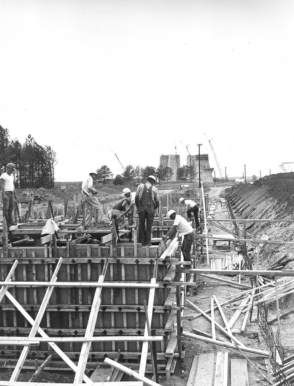
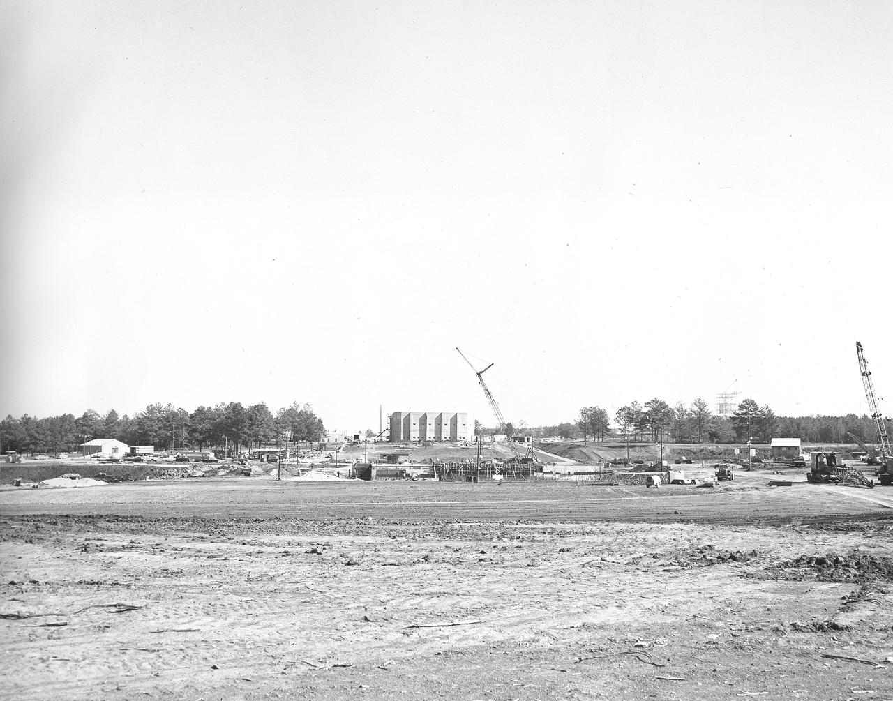
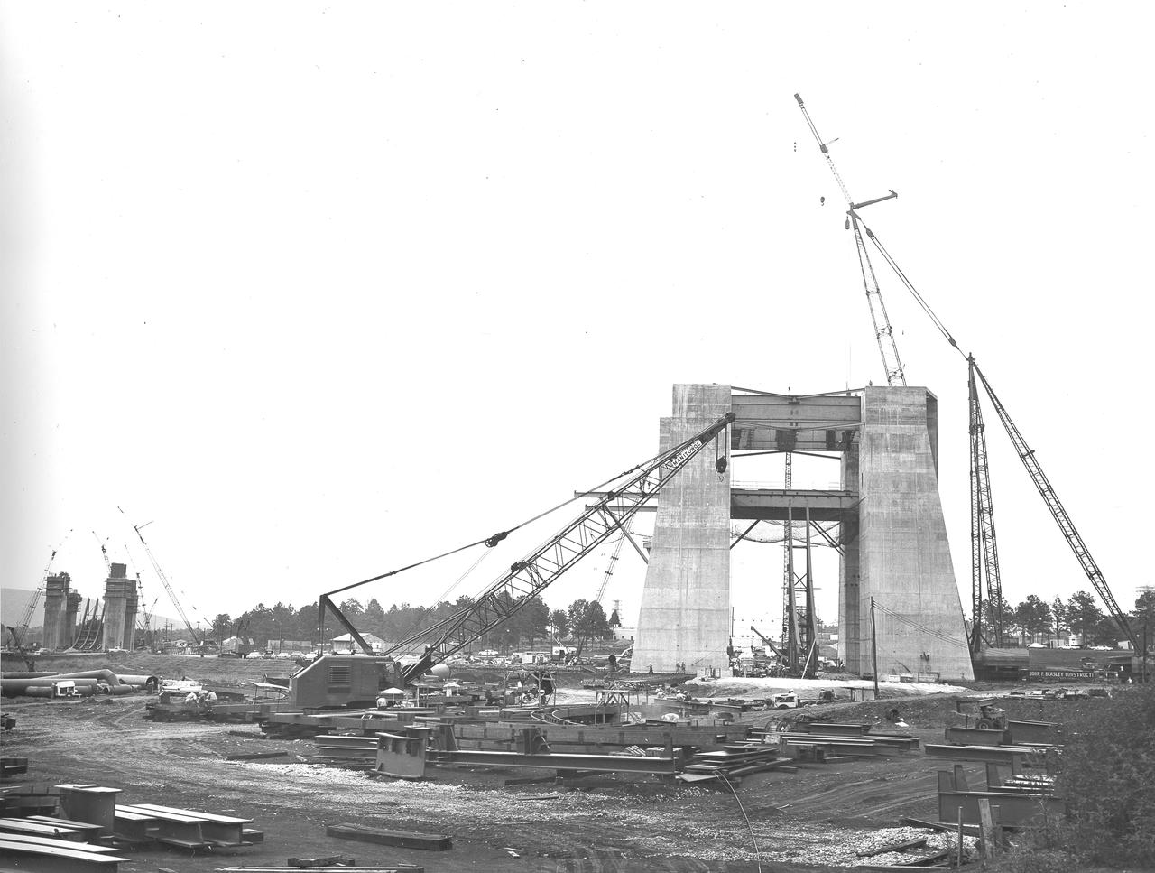
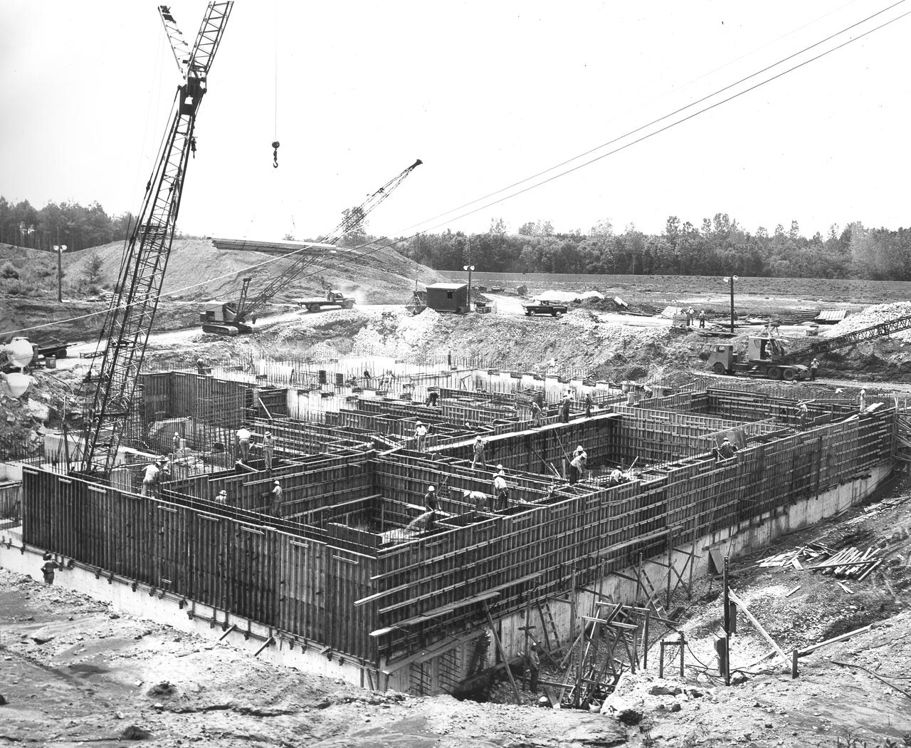
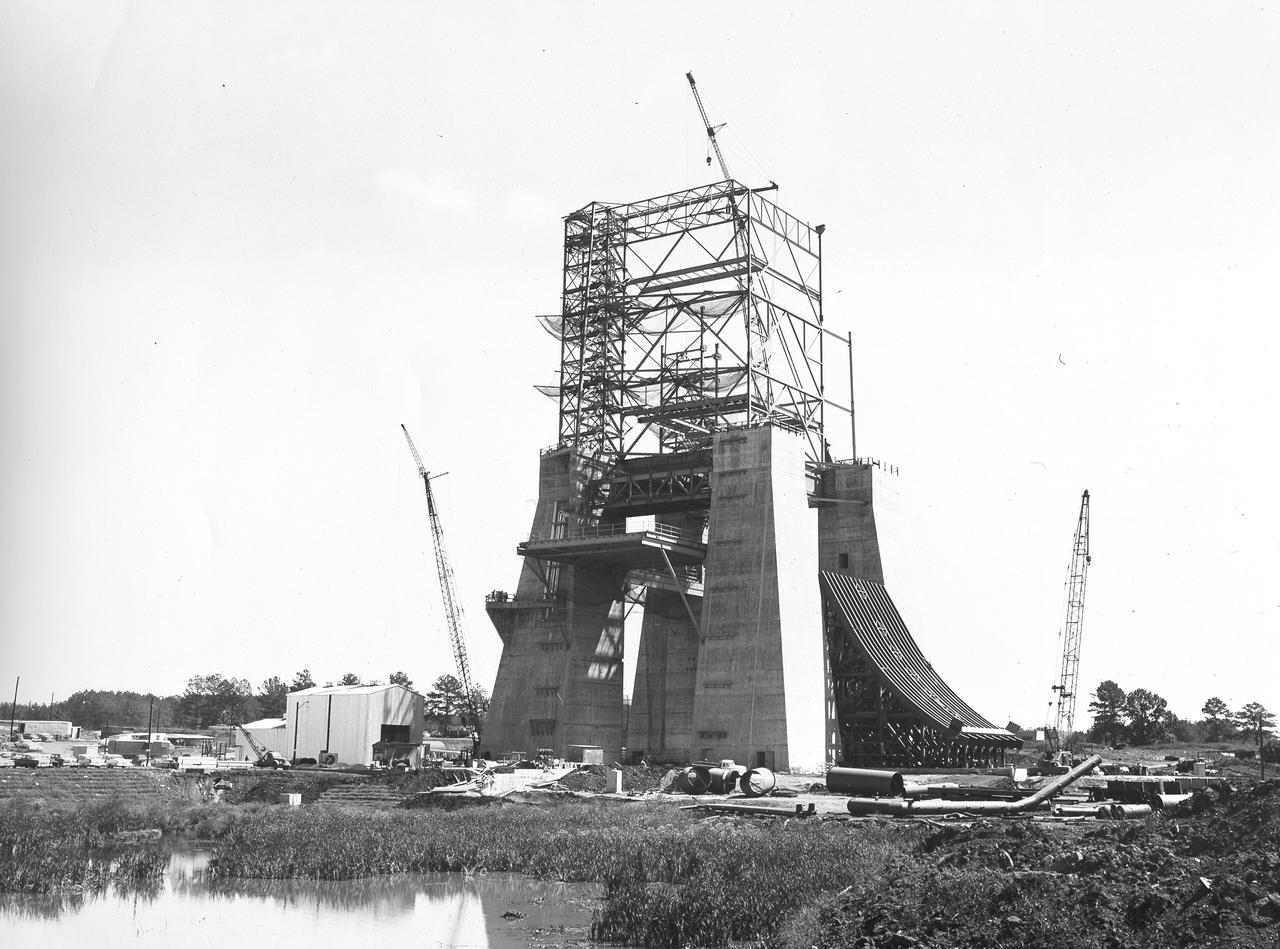
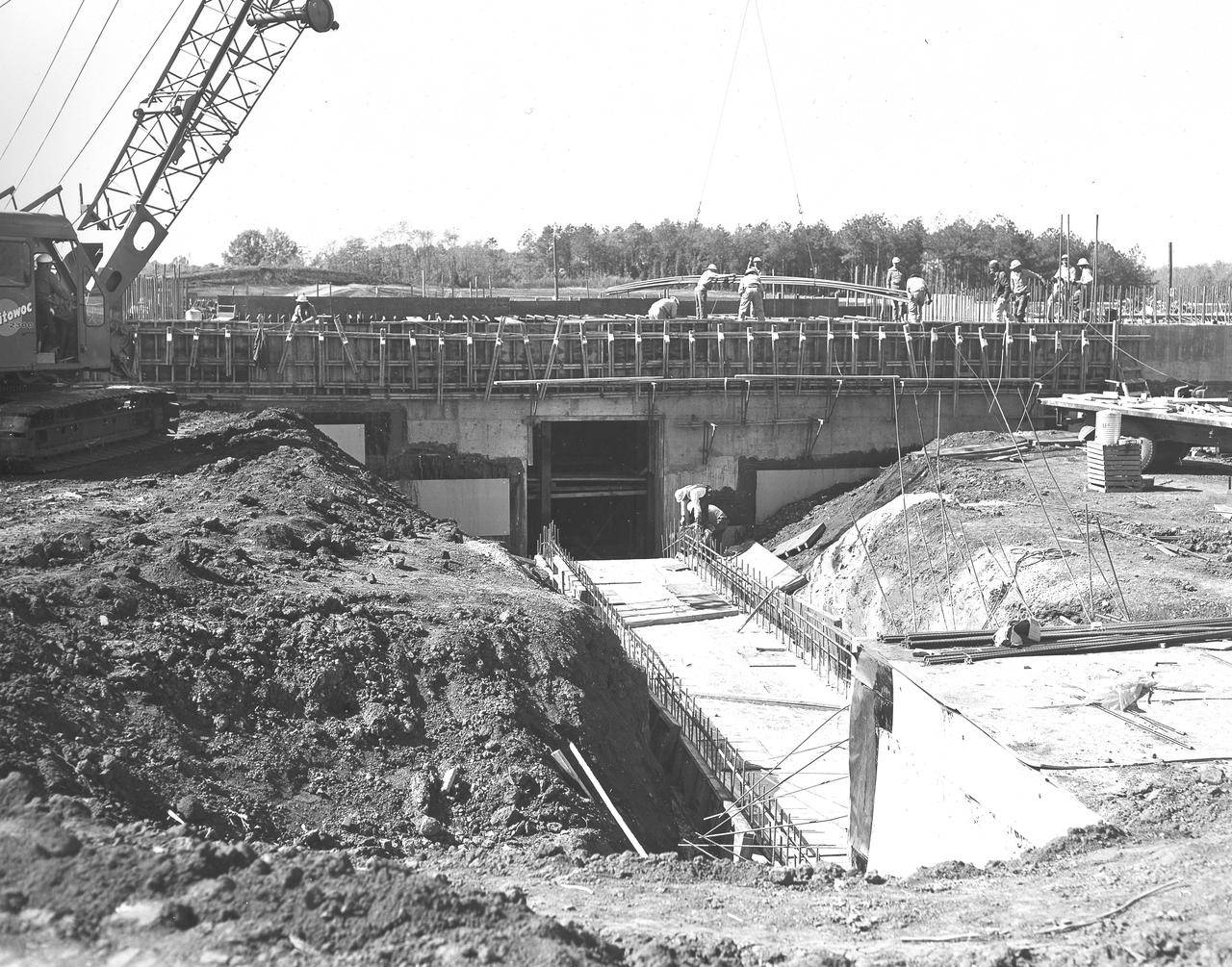
At its founding, the Marshall Space Flight Center (MSFC) inherited the Army’s Jupiter and Redstone test stands, but much larger facilities were needed for the giant stages of the Saturn V. From 1960 to 1964, the existing stands were remodeled and a sizable new test area was developed. The new comprehensive test complex for propulsion and structural dynamics was unique within the nation and the free world, and they remain so today because they were constructed with foresight to meet the future as well as on going needs. Construction of the S-IC Static test stand complex began in 1961 in the west test area of MSFC, and was completed in 1964. The S-IC static test stand was designed to develop and test the 138-ft long and 33-ft diameter Saturn V S-IC first stage, or booster stage, weighing in at 280,000 pounds. Required to hold down the brute force of a 7,500,000-pound thrust produced by 5 F-1 engines, the S-IC static test stand was designed and constructed with the strength of hundreds of tons of steel and 12,000,000 pounds of cement, planted down to bedrock 40 feet below ground level. The foundation walls, constructed with concrete and steel, are 4 feet thick. The base structure consists of four towers with 40-foot-thick walls extending upward 144 feet above ground level. The structure was topped by a crane with a 135-foot boom. With the boom in the upright position, the stand was given an overall height of 405 feet, placing it among the highest structures in Alabama at the time. In addition to the stand itself, related facilities were constructed during this time. Built directly east of the test stand was the Block House, which served as the control center for the test stand. The two were connected by a narrow access tunnel which housed the cables for the controls. Again to the east, just south of the Block House, was a newly constructed Pump House. Its function was to provide water to the stand to prevent melting damage during testing. The water was sprayed through small holes in the stand’s 1900 ton water deflector at the rate of 320,000 gallons per minute. In this photo, taken May 22, 1963, the Pump House is undergoing construction.
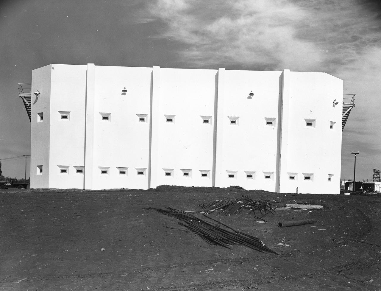
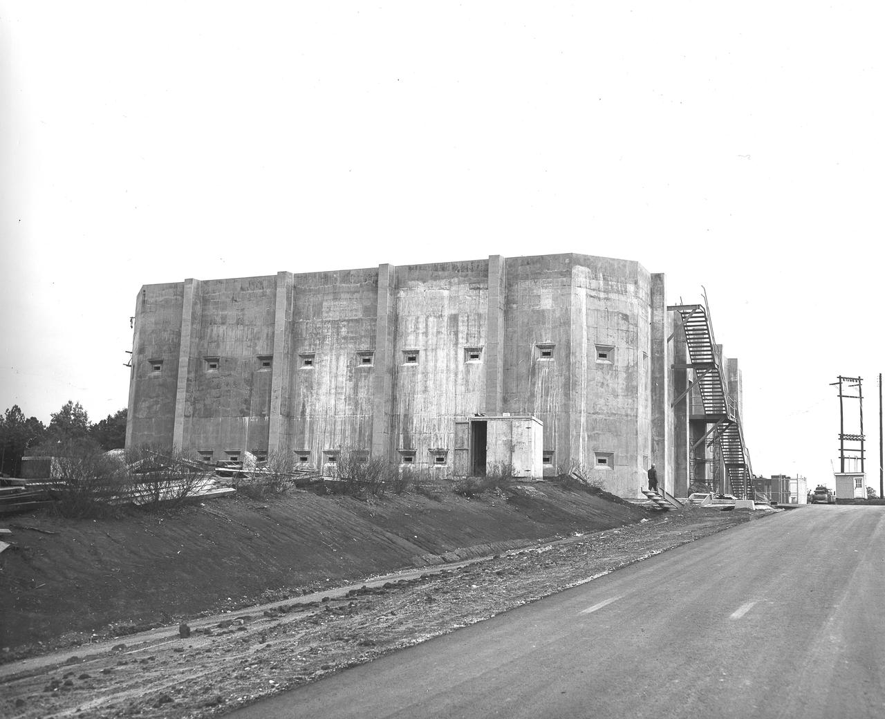
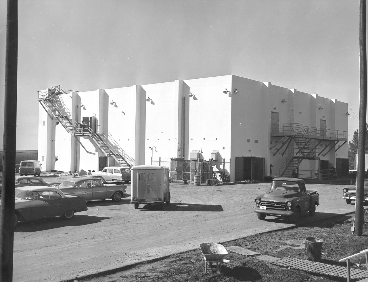
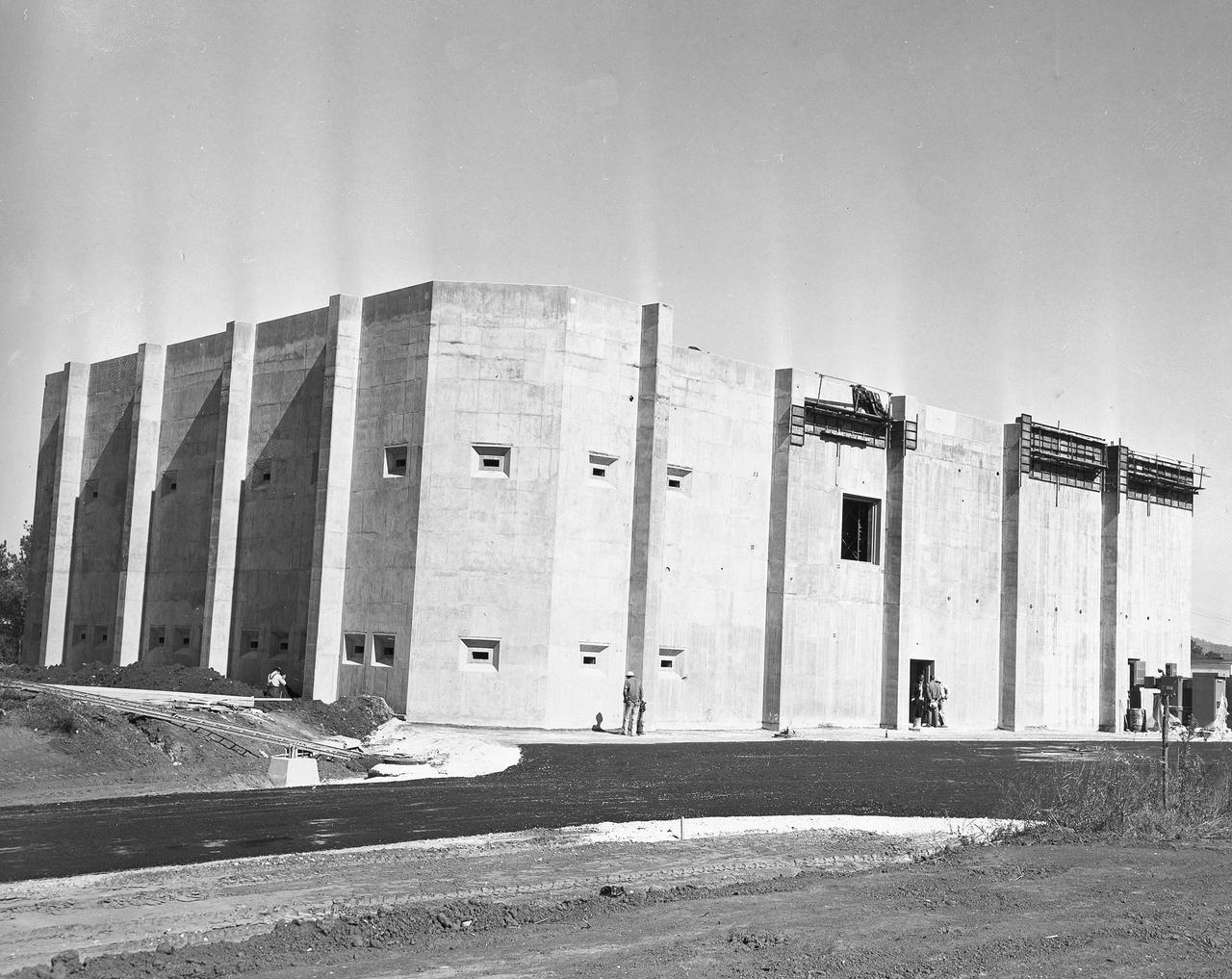
At its founding, the Marshall Space Flight Center (MSFC) inherited the Army’s Jupiter and Redstone test stands, but much larger facilities were needed for the giant stages of the Saturn V. From 1960 to 1964, the existing stands were remodeled and a sizable new test area was developed. The new comprehensive test complex for propulsion and structural dynamics was unique within the nation and the free world, and they remain so today because they were constructed with foresight to meet the future as well as on going needs. Construction of the S-IC Static test stand complex began in 1961 in the west test area of MSFC, and was completed in 1964. The S-IC static test stand was designed to develop and test the 138-ft long and 33-ft diameter Saturn V S-IC first stage, or booster stage, weighing in at 280,000 pounds. Required to hold down the brute force of a 7,500,000-pound thrust produced by 5 F-1 engines, the S-IC static test stand was designed and constructed with the strength of hundreds of tons of steel and 12,000,000 pounds of cement, planted down to bedrock 40 feet below ground level. The foundation walls, constructed with concrete and steel, are 4 feet thick. The base structure consists of four towers with 40-foot-thick walls extending upward 144 feet above ground level. The structure was topped by a crane with a 135-foot boom. With the boom in the upright position, the stand was given an overall height of 405 feet, placing it among the highest structures in Alabama at the time. In addition to the stand itself, related facilities were constructed during this time. Built directly east of the test stand was the Block House, which served as the control center for the test stand. The two were connected by a narrow access tunnel which housed the cables for the controls. This photograph, taken February 25, 1963, gives a close up look at the completed Block House. The side shown faces the S-IC Test Stand.
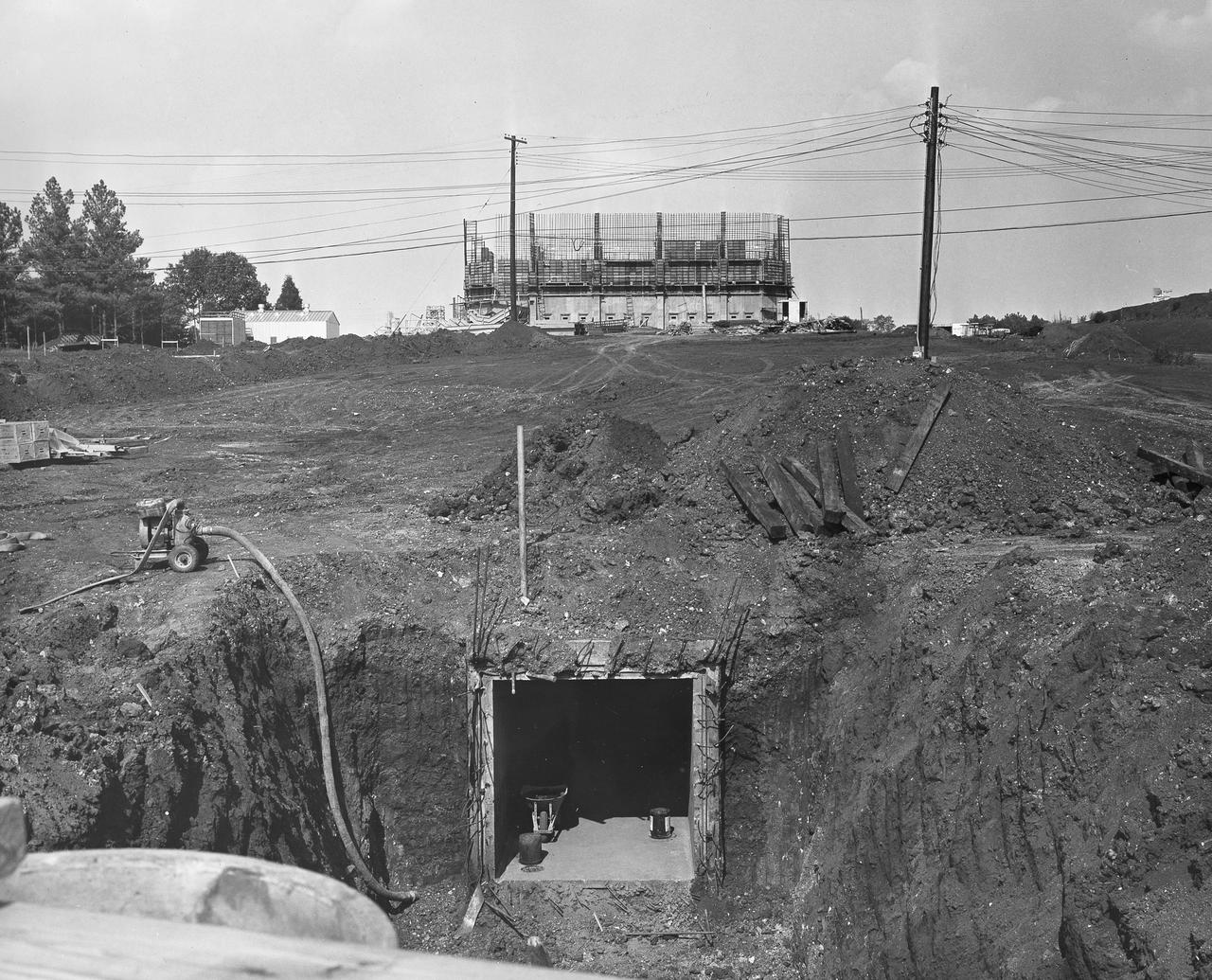
At its founding, the Marshall Space Flight Center (MSFC) inherited the Army’s Jupiter and Redstone test stands, but much larger facilities were needed for the giant stages of the Saturn V. From 1960 to 1964, the existing stands were remodeled and a sizable new test area was developed. The new comprehensive test complex for propulsion and structural dynamics was unique within the nation and the free world, and they remain so today because they were constructed with foresight to meet the future as well as on going needs. Construction of the S-IC Static test stand complex began in 1961 in the west test area of MSFC, and was completed in 1964. The S-IC static test stand was designed to develop and test the 138-ft long and 33-ft diameter Saturn V S-IC first stage, or booster stage, weighing in at 280,000 pounds. Required to hold down the brute force of a 7,500,000-pound thrust produced by 5 F-1 engines, the S-IC static test stand was designed and constructed with the strength of hundreds of tons of steel and 12,000,000 pounds of cement, planted down to bedrock 40 feet below ground level. The foundation walls, constructed with concrete and steel, are 4 feet thick. The base structure consists of four towers with 40-foot-thick walls extending upward 144 feet above ground level. The structure was topped by a crane with a 135-foot boom. With the boom in the upright position, the stand was given an overall height of 405 feet, placing it among the highest structures in Alabama at the time. In addition to the stand itself, related facilities were constructed during this time. Built directly east of the test stand was the Block House, which served as the control center for the test stand. The two were connected by a narrow access tunnel which housed the cables for the controls. This construction photo taken August 17, 1962 depicts a view of the Block House from the test stand site. The tunnel opening is visible in the forefront center of the photo.
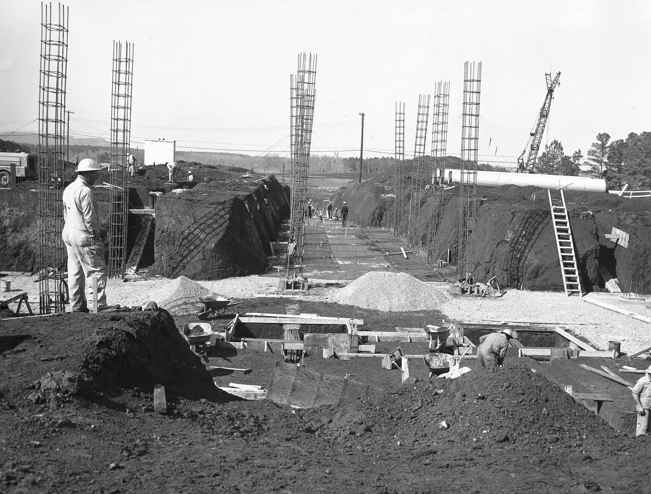
At its founding, the Marshall Space Flight Center (MSFC) inherited the Army’s Jupiter and Redstone test stands, but much larger facilities were needed for the giant stages of the Saturn V. From 1960 to 1964, the existing stands were remodeled and a sizable new test area was developed. The new comprehensive test complex for propulsion and structural dynamics was unique within the nation and the free world, and they remain so today because they were constructed with foresight to meet the future as well as on going needs. Construction of the S-IC Static test stand complex began in 1961 in the west test area of MSFC, and was completed in 1964. The S-IC static test stand was designed to develop and test the 138-ft long and 33-ft diameter Saturn V S-IC first stage, or booster stage, weighing in at 280,000 pounds. Required to hold down the brute force of a 7,500,000-pound thrust produced by 5 F-1 engines, the S-IC static test stand was designed and constructed with the strength of hundreds of tons of steel and 12,000,000 pounds of cement, planted down to bedrock 40 feet below ground level. The foundation walls, constructed with concrete and steel, are 4 feet thick. The base structure consists of four towers with 40-foot-thick walls extending upward 144 feet above ground level. The structure was topped by a crane with a 135-foot boom. With the boom in the upright position, the stand was given an overall height of 405 feet, placing it among the highest structures in Alabama at the time. In addition to the stand itself, related facilities were constructed during this time. Built directly east of the test stand was the Block House, which served as the control center for the test stand. The two were connected by a narrow tunnel which housed the cables for the controls. Again to the east, just south of the Block House, was a newly constructed Pump House. Its function was to provide water to the stand to prevent melting damage during testing. The water was sprayed through small holes in the stand’s 1900 ton water deflector at the rate of 320,000 gallons per minute. In this photo, taken March 20, 1962, construction of the Pump House area is well underway.
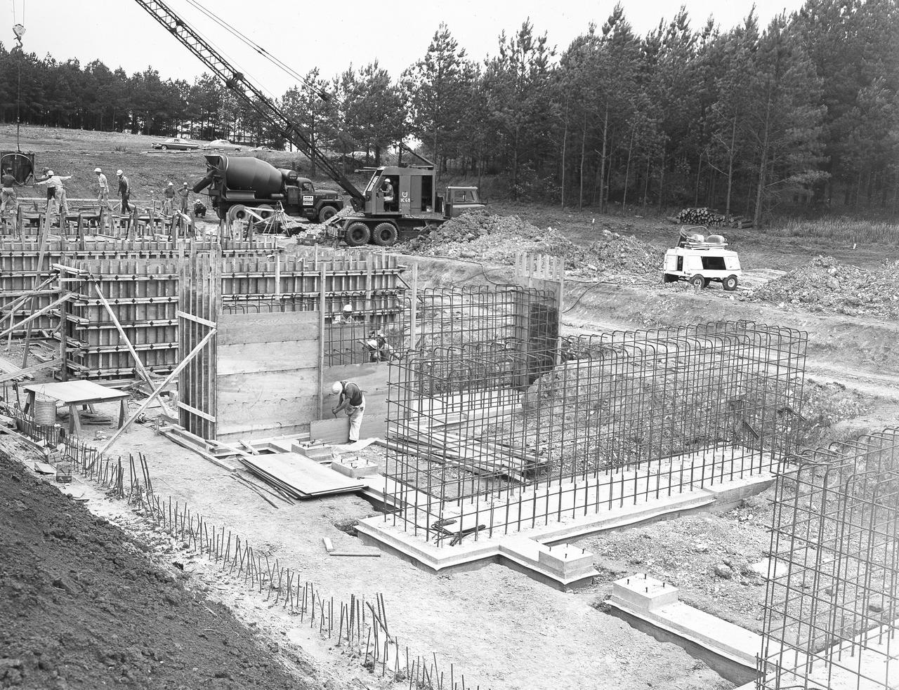
At its founding, the Marshall Space Flight Center (MSFC) inherited the Army’s Jupiter and Redstone test stands, but much larger facilities were needed for the giant stages of the Saturn V. From 1960 to 1964, the existing stands were remodeled and a sizable new test area was developed. The new comprehensive test complex for propulsion and structural dynamics was unique within the nation and the free world, and they remain so today because they were constructed with foresight to meet the future as well as on going needs. Construction of the S-IC Static test stand complex began in 1961 in the west test area of MSFC, and was completed in 1964. The S-IC static test stand was designed to develop and test the 138-ft long and 33-ft diameter Saturn V S-IC first stage, or booster stage, weighing in at 280,000 pounds. Required to hold down the brute force of a 7,500,000-pound thrust produced by 5 F-1 engines, the S-IC static test stand was designed and constructed with the strength of hundreds of tons of steel and 12,000,000 pounds of cement, planted down to bedrock 40 feet below ground level. The foundation walls, constructed with concrete and steel, are 4 feet thick. The base structure consists of four towers with 40-foot-thick walls extending upward 144 feet above ground level. The structure was topped by a crane with a 135-foot boom. With the boom in the upright position, the stand was given an overall height of 405 feet, placing it among the highest structures in Alabama at the time. In addition to the stand itself, related facilities were constructed during this time. Built directly east of the test stand was the Block House, which served as the control center for the test stand. The two were connected by a narrow access tunnel which housed the cables for the controls. Again to the east, just south of the Block House, was a newly constructed Pump House. Its function was to provide water to the stand to prevent melting damage during testing. The water was sprayed through small holes in the stand’s 1900 ton water deflector at the rate of 320,000 gallons per minute. In this photo, taken May 22, 1963, the Pump House is undergoing construction.
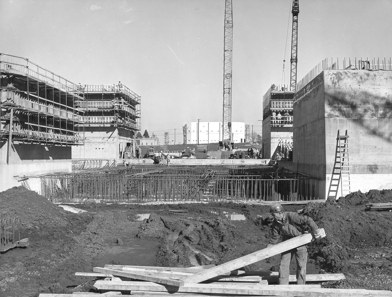
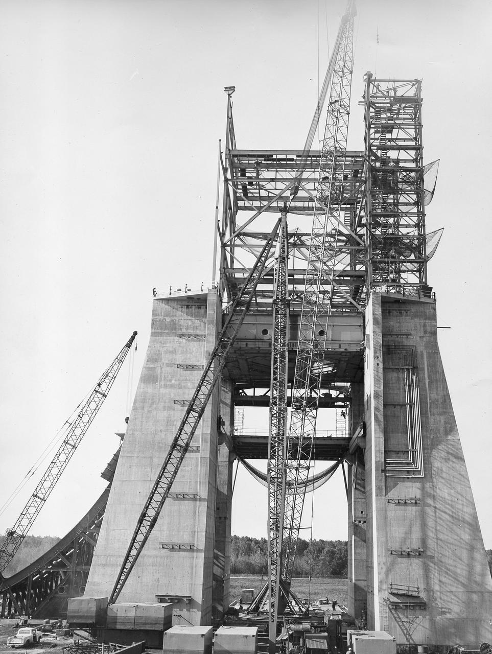
At its founding, the Marshall Space Flight Center (MSFC) inherited the Army’s Jupiter and Redstone test stands, but much larger facilities were needed for the giant stages of the Saturn V. From 1960 to 1964, the existing stands were remodeled and a sizable new test area was developed. The new comprehensive test complex for propulsion and structural dynamics was unique within the nation and the free world, and they remain so today because they were constructed with foresight to meet the future as well as on going needs. Construction of the S-IC Static test stand complex began in 1961 in the west test area of MSFC, and was completed in 1964. The S-IC static test stand was designed to develop and test the 138-ft long and 33-ft diameter Saturn V S-IC first stage, or booster stage, weighing in at 280,000 pounds. Required to hold down the brute force of a 7,500,000-pound thrust produced by 5 F-1 engines, the S-IC static test stand was designed and constructed with the strength of hundreds of tons of steel and 12,000,000 pounds of cement, planted down to bedrock 40 feet below ground level. The foundation walls, constructed with concrete and steel, are 4 feet thick. The base structure consists of four towers with 40-foot-thick walls extending upward 144 feet above ground level. The structure was topped by a crane with a 135-foot boom. With the boom in the upright position, the stand was given an overall height of 405 feet, placing it among the highest structures in Alabama at the time. In addition to the stand itself, related facilities were constructed during this time. Built directly east of the test stand was the Block House, which served as the control center for the test stand. The two were connected by a narrow access tunnel which housed the cables for the controls. This photograph taken February 4, 1963, gives an impressive look at the Block House looking directly through the ever-growing four towers of the S-IC Test Stand.
At its founding, the Marshall Space Flight Center (MSFC) inherited the Army’s Jupiter and Redstone test stands, but much larger facilities were needed for the giant stages of the Saturn V. From 1960 to 1964, the existing stands were remodeled and a sizable new test area was developed. The new comprehensive test complex for propulsion and structural dynamics was unique within the nation and the free world, and they remain so today because they were constructed with foresight to meet the future as well as on going needs. Construction of the S-IC Static test stand complex began in 1961 in the west test area of MSFC, and was completed in 1964. The S-IC static test stand was designed to develop and test the 138-ft long and 33-ft diameter Saturn V S-IC first stage, or booster stage, weighing in at 280,000 pounds. Required to hold down the brute force of a 7,500,000-pound thrust produced by 5 F-1 engines, the S-IC static test stand was designed and constructed with the strength of hundreds of tons of steel and 12,000,000 pounds of cement, planted down to bedrock 40 feet below ground level. The foundation walls, constructed with concrete and steel, are 4 feet thick. The base structure consists of four towers with 40-foot-thick walls extending upward 144 feet above ground level. The structure was topped by a crane with a 135-foot boom. With the boom in the upright position, the stand was given an overall height of 405 feet, placing it among the highest structures in Alabama at the time. In addition to the stand itself, related facilities were constructed during this time. Built directly east of the test stand was the Block House, which served as the control center for the test stand. The two were connected by a narrow access tunnel which housed the cables for the controls. This distant construction photo, taken October 26, 1962, depicts a view of the Block House and test stand site.
At its founding, the Marshall Space Flight Center (MSFC) inherited the Army’s Jupiter and Redstone test stands, but much larger facilities were needed for the giant stages of the Saturn V. From 1960 to 1964, the existing stands were remodeled and a sizable new test area was developed. The new comprehensive test complex for propulsion and structural dynamics was unique within the nation and the free world, and they remain so today because they were constructed with foresight to meet the future as well as on going needs. Construction of the S-IC Static test stand complex began in 1961 in the west test area of MSFC, and was completed in 1964. The S-IC static test stand was designed to develop and test the 138-ft long and 33-ft diameter Saturn V S-IC first stage, or booster stage, weighing in at 280,000 pounds. Required to hold down the brute force of a 7,500,000-pound thrust produced by 5 F-1 engines, the S-IC static test stand was designed and constructed with the strength of hundreds of tons of steel and 12,000,000 pounds of cement, planted down to bedrock 40 feet below ground level. The foundation walls, constructed with concrete and steel, are 4 feet thick. The base structure consists of four towers with 40-foot-thick walls extending upward 144 feet above ground level. The structure was topped by a crane with a 135-foot boom. With the boom in the upright position, the stand was given an overall height of 405 feet, placing it among the highest structures in Alabama at the time. In addition to the stand itself, related facilities were constructed during this time. Built to the east was a newly constructed Pump House. Its function was to provide water to the stand to prevent melting damage during testing. The water was sprayed through small holes in the stand’s 1900 ton flame deflector at the rate of 320,000 gallons per minute. In this photo, taken August 12, 1963, the S-IC stand has received some of its internal components. Directly in the center is the framework that houses the flame deflector. The F-1 test stand, designed and built to test a single F-1 engine, can be seen on the left side of the photo.
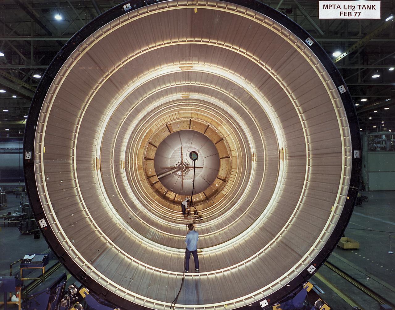
This photograph shows an inside view of a liquid hydrogen tank for the Space Shuttle external tank (ET) Main Propulsion Test Article (MPTA). The ET provides liquid hydrogen and liquid oxygen to the Shuttle's three main engines during the first 8.5 minutes of flight. At 154-feet long and more than 27-feet in diameter, the ET is the largest component of the Space Shuttle, the structural backbone of the entire Shuttle system, and is the only part of the vehicle that is not reusable. The ET is manufactured at the Michoud Assembly Facility near New Orleans, Louisiana, by the Martin Marietta Corporation under management of the Marshall Space Flight Center.
At its founding, the Marshall Space Flight Center (MSFC) inherited the Army’s Jupiter and Redstone test stands, but much larger facilities were needed for the giant stages of the Saturn V. From 1960 to 1964, the existing stands were remodeled and a sizable new test area was developed. The new comprehensive test complex for propulsion and structural dynamics was unique within the nation and the free world, and they remain so today because they were constructed with foresight to meet the future as well as on going needs. Construction of the S-IC Static test stand complex began in 1961 in the west test area of MSFC, and was completed in 1964. The S-IC static test stand was designed to develop and test the 138-ft long and 33-ft diameter Saturn V S-IC first stage, or booster stage, weighing in at 280,000 pounds. Required to hold down the brute force of a 7,500,000-pound thrust produced by 5 F-1 engines, the S-IC static test stand was designed and constructed with the strength of hundreds of tons of steel and 12,000,000 pounds of cement, planted down to bedrock 40 feet below ground level. The foundation walls, constructed with concrete and steel, are 4 feet thick. The base structure consists of four towers with 40-foot-thick walls extending upward 144 feet above ground level. The structure was topped by a crane with a 135-foot boom. With the boom in the upright position, the stand was given an overall height of 405 feet, placing it among the highest structures in Alabama at the time. In addition to the stand itself, related facilities were constructed during this time. Built directly east of the test stand was the Block House, which served as the control center for the test stand. The two were connected by a narrow access tunnel which housed the cables for the controls. This construction photo, taken November 15, 1962, depicts a view of the Block House.
At its founding, the Marshall Space Flight Center (MSFC) inherited the Army’s Jupiter and Redstone test stands, but much larger facilities were needed for the giant stages of the Saturn V. From 1960 to 1964, the existing stands were remodeled and a sizable new test area was developed. The new comprehensive test complex for propulsion and structural dynamics was unique within the nation and the free world, and they remain so today because they were constructed with foresight to meet the future as well as on going needs. Construction of the S-IC Static test stand complex began in 1961 in the west test area of MSFC, and was completed in 1964. The S-IC static test stand was designed to develop and test the 138-ft long and 33-ft diameter Saturn V S-IC first stage, or booster stage, weighing in at 280,000 pounds. Required to hold down the brute force of a 7,500,000-pound thrust produced by 5 F-1 engines, the S-IC static test stand was designed and constructed with the strength of hundreds of tons of steel and 12,000,000 pounds of cement, planted down to bedrock 40 feet below ground level. The foundation walls, constructed with concrete and steel, are 4 feet thick. The base structure consists of four towers with 40-foot-thick walls extending upward 144 feet above ground level. The structure was topped by a crane with a 135-foot boom. With the boom in the upright position, the stand was given an overall height of 405 feet, placing it among the highest structures in Alabama at the time. In addition to the stand itself, related facilities were constructed during this time. Built directly east of the test stand was the Block House, which served as the control center for the test stand. The two were connected by a narrow access tunnel which housed the cables for the controls. This construction photo, taken July 3, 1962, depicts the Block House with a portion of its concrete walls poured and exposed while many are still in the forms stage.
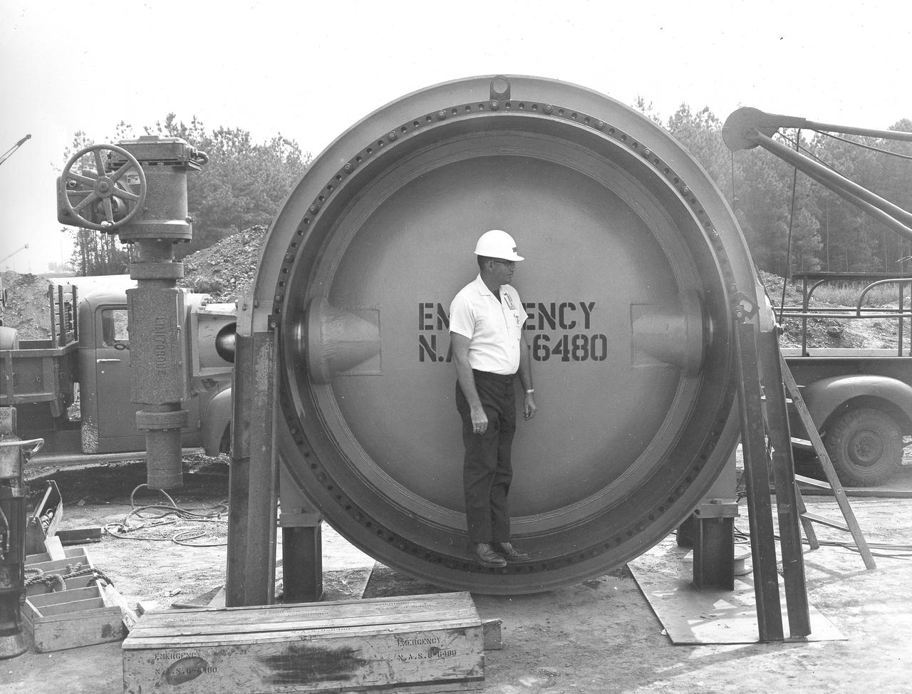
At its founding, the Marshall Space Flight Center (MSFC) inherited the Army’s Jupiter and Redstone test stands, but much larger facilities were needed for the giant stages of the Saturn V. From 1960 to 1964, the existing stands were remodeled and a sizable new test area was developed. The new comprehensive test complex for propulsion and structural dynamics was unique within the nation and the free world, and they remain so today because they were constructed with foresight to meet the future as well as on going needs. Construction of the S-IC Static test stand complex began in 1961 in the west test area of MSFC, and was completed in 1964. The S-IC static test stand was designed to develop and test the 138-ft long and 33-ft diameter Saturn V S-IC first stage, or booster stage, weighing in at 280,000 pounds. Required to hold down the brute force of a 7,500,000-pound thrust produced by 5 F-1 engines, the S-IC static test stand was designed and constructed with the strength of hundreds of tons of steel and 12,000,000 pounds of cement, planted down to bedrock 40 feet below ground level. The foundation walls, constructed with concrete and steel, are 4 feet thick. The base structure consists of four towers with 40-foot-thick walls extending upward 144 feet above ground level. The structure was topped by a crane with a 135-foot boom. With the boom in the upright position, the stand was given an overall height of 405 feet, placing it among the highest structures in Alabama at the time. In addition to the stand itself, related facilities were constructed during this time. Built northeast of the stand was a newly constructed Pump House. Its function was to provide water to the stand to prevent melting damage during testing. The water was sprayed through small holes in the stand’s 1900 ton flame deflector at the rate of 320,000 gallons per minute. In this photograph, a construction worker demonstrates the size of the massive water valve that was used in the testing cooling process.
At its founding, the Marshall Space Flight Center (MSFC) inherited the Army’s Jupiter and Redstone test stands, but much larger facilities were needed for the giant stages of the Saturn V. From 1960 to 1964, the existing stands were remodeled and a sizable new test area was developed. The new comprehensive test complex for propulsion and structural dynamics was unique within the nation and the free world, and they remain so today because they were constructed with foresight to meet the future as well as on going needs. Construction of the S-IC Static test stand complex began in 1961 in the west test area of MSFC, and was completed in 1964. The S-IC static test stand was designed to develop and test the 138-ft long and 33-ft diameter Saturn V S-IC first stage, or booster stage, weighing in at 280,000 pounds. Required to hold down the brute force of a 7,500,000-pound thrust produced by 5 F-1 engines, the S-IC static test stand was designed and constructed with the strength of hundreds of tons of steel and 12,000,000 pounds of cement, planted down to bedrock 40 feet below ground level. The foundation walls, constructed with concrete and steel, are 4 feet thick. The base structure consists of four towers with 40-foot-thick walls extending upward 144 feet above ground level. The structure was topped by a crane with a 135-foot boom. With the boom in the upright position, the stand was given an overall height of 405 feet, placing it among the highest structures in Alabama at the time. In addition to the stand itself, related facilities were constructed during this time. Built directly east of the test stand was the Block House, which served as the control center for the test stand. The two were connected by a narrow access tunnel which housed the cables for the controls. In this photo taken February 4, 1963, the Block House exterior is complete.
At its founding, the Marshall Space Flight Center (MSFC) inherited the Army’s Jupiter and Redstone test stands, but much larger facilities were needed for the giant stages of the Saturn V. From 1960 to 1964, the existing stands were remodeled and a sizable new test area was developed. The new comprehensive test complex for propulsion and structural dynamics was unique within the nation and the free world, and they remain so today because they were constructed with foresight to meet the future as well as on going needs. Construction of the S-IC Static test stand complex began in 1961 in the west test area of MSFC, and was completed in 1964. The S-IC static test stand was designed to develop and test the 138-ft long and 33-ft diameter Saturn V S-IC first stage, or booster stage, weighing in at 280,000 pounds. Required to hold down the brute force of a 7,500,000-pound thrust produced by 5 F-1 engines, the S-IC static test stand was designed and constructed with the strength of hundreds of tons of steel and 12,000,000 pounds of cement, planted down to bedrock 40 feet below ground level. The foundation walls, constructed with concrete and steel, are 4 feet thick. The base structure consists of four towers with 40-foot-thick walls extending upward 144 feet above ground level. The structure was topped by a crane with a 135-foot boom. With the boom in the upright position, the stand was given an overall height of 405 feet, placing it among the highest structures in Alabama at the time. In addition to the stand itself, related facilities were constructed during this time. Built to the northeast of the stand was a newly constructed Pump House. Its function was to provide water to the stand to prevent melting damage during testing. The water was sprayed through small holes in the stand’s 1900 ton flame deflector at the rate of 320,000 gallons per minute. In this photo of the S-IC test stand, taken September 25, 1963, the flame deflector can be seen rotated to the outside on the right. The deflector was assembled on tracks for mobility.
At its founding, the Marshall Space Flight Center (MSFC) inherited the Army’s Jupiter and Redstone test stands, but much larger facilities were needed for the giant stages of the Saturn V. From 1960 to 1964, the existing stands were remodeled and a sizable new test area was developed. The new comprehensive test complex for propulsion and structural dynamics was unique within the nation and the free world, and they remain so today because they were constructed with foresight to meet the future as well as on going needs. Construction of the S-IC Static test stand complex began in 1961 in the west test area of MSFC, and was completed in 1964. The S-IC static test stand was designed to develop and test the 138-ft long and 33-ft diameter Saturn V S-IC first stage, or booster stage, weighing in at 280,000 pounds. Required to hold down the brute force of a 7,500,000-pound thrust produced by 5 F-1 engines, the S-IC static test stand was designed and constructed with the strength of hundreds of tons of steel and 12,000,000 pounds of cement, planted down to bedrock 40 feet below ground level. The foundation walls, constructed with concrete and steel, are 4 feet thick. The base structure consists of four towers with 40-foot-thick walls extending upward 144 feet above ground level. The structure was topped by a crane with a 135-foot boom. With the boom in the upright position, the stand was given an overall height of 405 feet, placing it among the highest structures in Alabama at the time. In addition to the stand itself, related facilities were constructed during this time. Built directly east of the test stand was the Block House, which served as the control center for the test stand. The two were connected by a narrow access tunnel which housed the cables for the controls. This construction photo, taken October 26, 1962, depicts a view of the Block House tunnel opening.
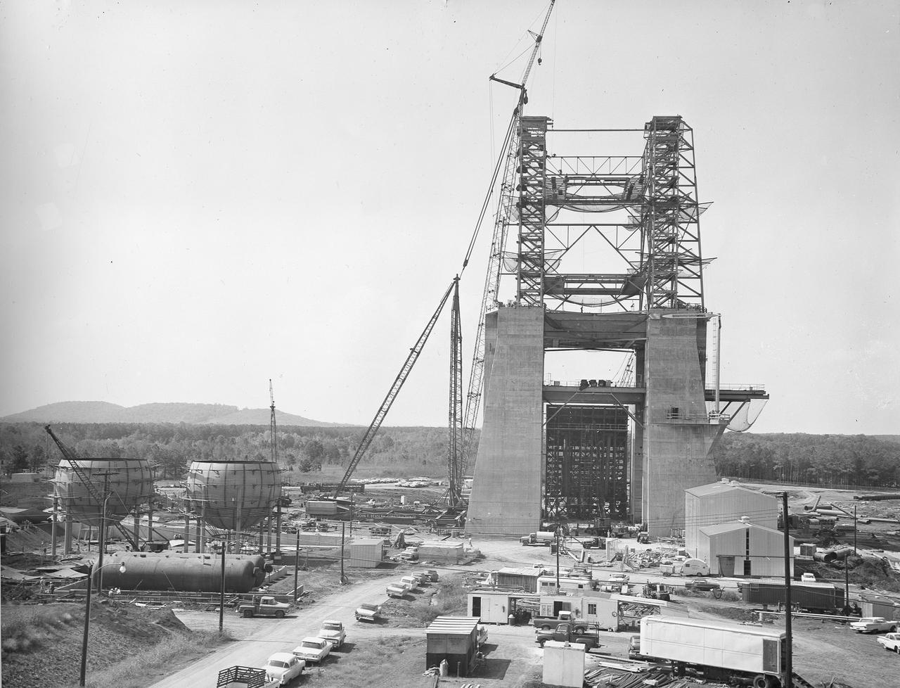
At its founding, the Marshall Space Flight Center (MSFC) inherited the Army’s Jupiter and Redstone test stands, but much larger facilities were needed for the giant stages of the Saturn V. From 1960 to 1964, the existing stands were remodeled and a sizable new test area was developed. The new comprehensive test complex for propulsion and structural dynamics was unique within the nation and the free world, and they remain so today because they were constructed with foresight to meet the future as well as on going needs. Construction of the S-IC Static test stand complex began in 1961 in the west test area of MSFC, and was completed in 1964. The S-IC static test stand was designed to develop and test the 138-ft long and 33-ft diameter Saturn V S-IC first stage, or booster stage, weighing in at 280,000 pounds. Required to hold down the brute force of a 7,500,000-pound thrust produced by 5 F-1 engines, the S-IC static test stand was designed and constructed with the strength of hundreds of tons of steel and 12,000,000 pounds of cement, planted down to bedrock 40 feet below ground level. The foundation walls, constructed with concrete and steel, are 4 feet thick. The base structure consists of four towers with 40-foot-thick walls extending upward 144 feet above ground level. The structure was topped by a crane with a 135-foot boom. With the boom in the upright position, the stand was given an overall height of 405 feet, placing it among the highest structures in Alabama at the time. In addition to the stand itself, related facilities were constructed during this time. Built to the northeast of the stand was a newly constructed Pump House. Its function was to provide water to the stand to prevent melting damage during testing. The water was sprayed through small holes in the stand’s 1900 ton flame deflector at the rate of 320,000 gallons per minute. In this photo of the S-IC test stand, taken October 2, 1963, the flame deflector can be seen in the bottom center portion of the stand. The deflector was assembled on tracks for mobility. To the left of the stand are two spherical hydrogen storage tanks.
At its founding, the Marshall Space Flight Center (MSFC) inherited the Army’s Jupiter and Redstone test stands, but much larger facilities were needed for the giant stages of the Saturn V. From 1960 to 1964, the existing stands were remodeled and a sizable new test area was developed. The new comprehensive test complex for propulsion and structural dynamics was unique within the nation and the free world, and they remain so today because they were constructed with foresight to meet the future as well as on going needs. Construction of the S-IC Static test stand complex began in 1961 in the west test area of MSFC, and was completed in 1964. The S-IC static test stand was designed to develop and test the 138-ft long and 33-ft diameter Saturn V S-IC first stage, or booster stage, weighing in at 280,000 pounds. Required to hold down the brute force of a 7,500,000-pound thrust produced by 5 F-1 engines, the S-IC static test stand was designed and constructed with the strength of hundreds of tons of steel and 12,000,000 pounds of cement, planted down to bedrock 40 feet below ground level. The foundation walls, constructed with concrete and steel, are 4 feet thick. The base structure consists of four towers with 40-foot-thick walls extending upward 144 feet above ground level. The structure was topped by a crane with a 135-foot boom. With the boom in the upright position, the stand was given an overall height of 405 feet, placing it among the highest structures in Alabama at the time. In addition to the stand itself, related facilities were constructed during this time. Built directly east of the test stand was the Block House, which served as the control center for the test stand. The two were connected by a narrow access tunnel which housed the cables for the controls. This construction photo, taken October 26, 1962, depicts a nearly completed view of the Block House.
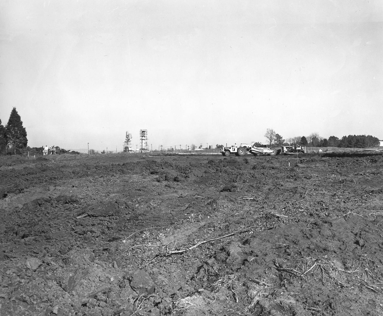
At its founding, the Marshall Space Flight Center (MSFC) inherited the Army’s Jupiter and Redstone test stands, but much larger facilities were needed for the giant stages of the Saturn V. From 1960 to 1964, the existing stands were remodeled and a sizable new test area was developed. The new comprehensive test complex for propulsion and structural dynamics was unique within the nation and the free world, and they remain so today because they were constructed with foresight to meet the future as well as on going needs. Construction of the S-IC Static test stand complex began in 1961 in the west test area of MSFC, and was completed in 1964. The S-IC static test stand was designed to develop and test the 138-ft long and 33-ft diameter Saturn V S-IC first stage, or booster stage, weighing in at 280,000 pounds. Required to hold down the brute force of a 7,500,000-pound thrust produced by 5 F-1 engines, the S-IC static test stand was designed and constructed with the strength of hundreds of tons of steel and 12,000,000 pounds of cement, planted down to bedrock 40 feet below ground level. The foundation walls, constructed with concrete and steel, are 4 feet thick. The base structure consists of four towers with 40-foot-thick walls extending upward 144 feet above ground level. The structure was topped by a crane with a 135-foot boom. With the boom in the upright position, the stand was given an overall height of 405 feet, placing it among the highest structures in Alabama at the time. In addition to the stand itself, related facilities were constructed during this time. Built directly east of the test stand was the Block House, which served as the control center for the test stand. The two were connected by a narrow access tunnel which housed the cables for the controls. This photo, taken February 2, 1962, shows the excavation of the Block House site.
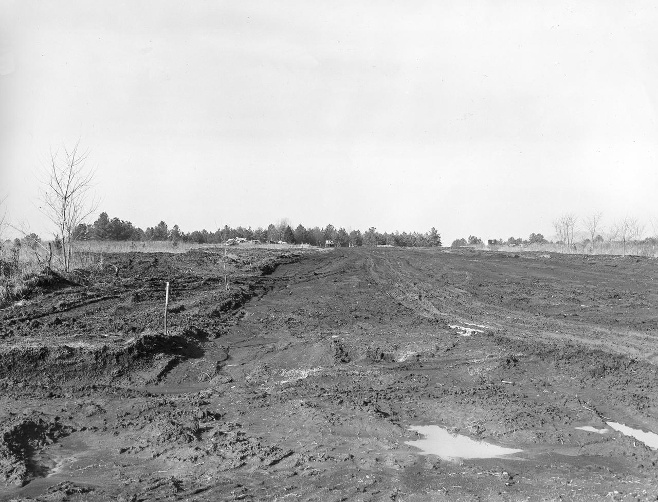
At its founding, the Marshall Space Flight Center (MSFC) inherited the Army’s Jupiter and Redstone test stands, but much larger facilities were needed for the giant stages of the Saturn V. From 1960 to 1964, the existing stands were remodeled and a sizable new test area was developed. The new comprehensive test complex for propulsion and structural dynamics was unique within the nation and the free world, and they remain so today because they were constructed with foresight to meet the future as well as on going needs. Construction of the S-IC Static test stand complex began in 1961 in the west test area of MSFC, and was completed in 1964. The S-IC static test stand was designed to develop and test the 138-ft long and 33-ft diameter Saturn V S-IC first stage, or booster stage, weighing in at 280,000 pounds. Required to hold down the brute force of a 7,500,000-pound thrust produced by 5 F-1 engines, the S-IC static test stand was designed and constructed with the strength of hundreds of tons of steel and 12,000,000 pounds of cement, planted down to bedrock 40 feet below ground level. The foundation walls, constructed with concrete and steel, are 4 feet thick. The base structure consists of four towers with 40-foot-thick walls extending upward 144 feet above ground level. The structure was topped by a crane with a 135-foot boom. With the boom in the upright position, the stand was given an overall height of 405 feet, placing it among the highest structures in Alabama at the time. In addition to the stand itself, related facilities were constructed during this time. Built directly east of the test stand was the Block House, which served as the control center for the test stand. The two were connected by a narrow access tunnel which housed the cables for the controls. This photo, taken January 23, 1962, shows the excavation of the Block House site.
At its founding, the Marshall Space Flight Center (MSFC) inherited the Army’s Jupiter and Redstone test stands, but much larger facilities were needed for the giant stages of the Saturn V. From 1960 to 1964, the existing stands were remodeled and a sizable new test area was developed. The new comprehensive test complex for propulsion and structural dynamics was unique within the nation and the free world, and they remain so today because they were constructed with foresight to meet the future as well as on going needs. Construction of the S-IC Static test stand complex began in 1961 in the west test area of MSFC, and was completed in 1964. The S-IC static test stand was designed to develop and test the 138-ft long and 33-ft diameter Saturn V S-IC first stage, or booster stage, weighing in at 280,000 pounds. Required to hold down the brute force of a 7,500,000-pound thrust produced by 5 F-1 engines, the S-IC static test stand was designed and constructed with the strength of hundreds of tons of steel and 12,000,000 pounds of cement, planted down to bedrock 40 feet below ground level. The foundation walls, constructed with concrete and steel, are 4 feet thick. The base structure consists of four towers with 40-foot-thick walls extending upward 144 feet above ground level. The structure was topped by a crane with a 135-foot boom. With the boom in the upright position, the stand was given an overall height of 405 feet, placing it among the highest structures in Alabama at the time. In addition to the stand itself, related facilities were constructed during this time. Built to the northeast of the stand was a newly constructed Pump House. Its function was to provide water to the stand to prevent melting damage during testing. The water was sprayed through small holes in the stand’s 1900 ton flame deflector at the rate of 320,000 gallons per minute. In this photo of the S-IC test stand, taken September 25, 1963, the flame deflector can be seen rotated to the outside on the left. The deflector was assembled on tracks for mobility.
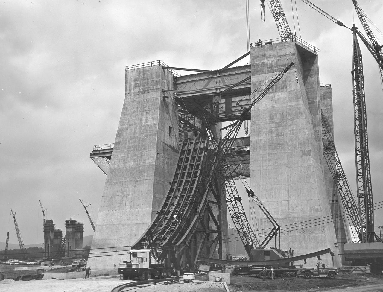
At its founding, the Marshall Space Flight Center (MSFC) inherited the Army’s Jupiter and Redstone test stands, but much larger facilities were needed for the giant stages of the Saturn V. From 1960 to 1964, the existing stands were remodeled and a sizable new test area was developed. The new comprehensive test complex for propulsion and structural dynamics was unique within the nation and the free world, and they remain so today because they were constructed with foresight to meet the future as well as on going needs. Construction of the S-IC Static test stand complex began in 1961 in the west test area of MSFC, and was completed in 1964. The S-IC static test stand was designed to develop and test the 138-ft long and 33-ft diameter Saturn V S-IC first stage, or booster stage, weighing in at 280,000 pounds. Required to hold down the brute force of a 7,500,000-pound thrust produced by 5 F-1 engines, the S-IC static test stand was designed and constructed with the strength of hundreds of tons of steel and 12,000,000 pounds of cement, planted down to bedrock 40 feet below ground level. The foundation walls, constructed with concrete and steel, are 4 feet thick. The base structure consists of four towers with 40-foot-thick walls extending upward 144 feet above ground level. The structure was topped by a crane with a 135-foot boom. With the boom in the upright position, the stand was given an overall height of 405 feet, placing it among the highest structures in Alabama at the time. In addition to the stand itself, related facilities were constructed during this time. Built northeast of the stand was a newly constructed Pump House. Its function was to provide water to the stand to prevent melting damage during testing. The water was sprayed through small holes in the stand’s 1900 ton flame deflector at the rate of 320,000 gallons per minute. In this photo, taken September 5, 1963, the flame deflector is being installed in the S-IC test stand.
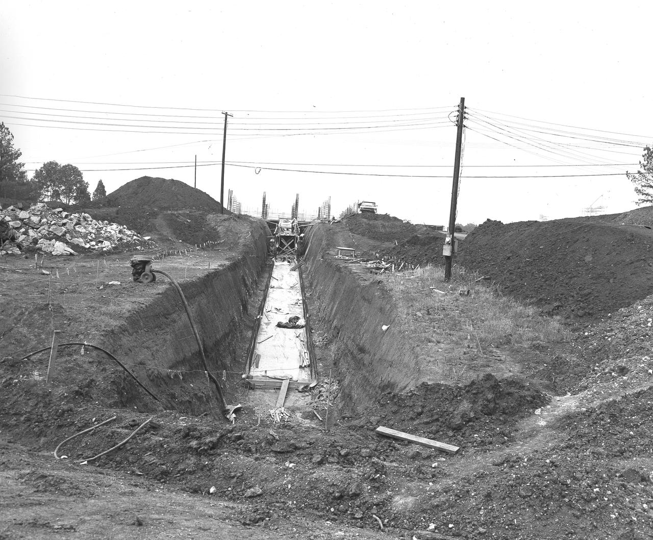
At its founding, the Marshall Space Flight Center (MSFC) inherited the Army’s Jupiter and Redstone test stands, but much larger facilities were needed for the giant stages of the Saturn V. From 1960 to 1964, the existing stands were remodeled and a sizable new test area was developed. The new comprehensive test complex for propulsion and structural dynamics was unique within the nation and the free world, and they remain so today because they were constructed with foresight to meet the future as well as on going needs. Construction of the S-IC Static test stand complex began in 1961 in the west test area of MSFC, and was completed in 1964. The S-IC static test stand was designed to develop and test the 138-ft long and 33-ft diameter Saturn V S-IC first stage, or booster stage, weighing in at 280,000 pounds. Required to hold down the brute force of a 7,500,000-pound thrust produced by 5 F-1 engines, the S-IC static test stand was designed and constructed with the strength of hundreds of tons of steel and 12,000,000 pounds of cement, planted down to bedrock 40 feet below ground level. The foundation walls, constructed with concrete and steel, are 4 feet thick. The base structure consists of four towers with 40-foot-thick walls extending upward 144 feet above ground level. The structure was topped by a crane with a 135-foot boom. With the boom in the upright position, the stand was given an overall height of 405 feet, placing it among the highest structures in Alabama at the time. In addition to the stand itself, related facilities were constructed during this time. Built directly east of the test stand was the Block House, which served as the control center for the test stand. The two were connected by a narrow tunnel which housed the cables for the controls. This photograph, taken on May 21, 1962 depicts the access tunnel construction.
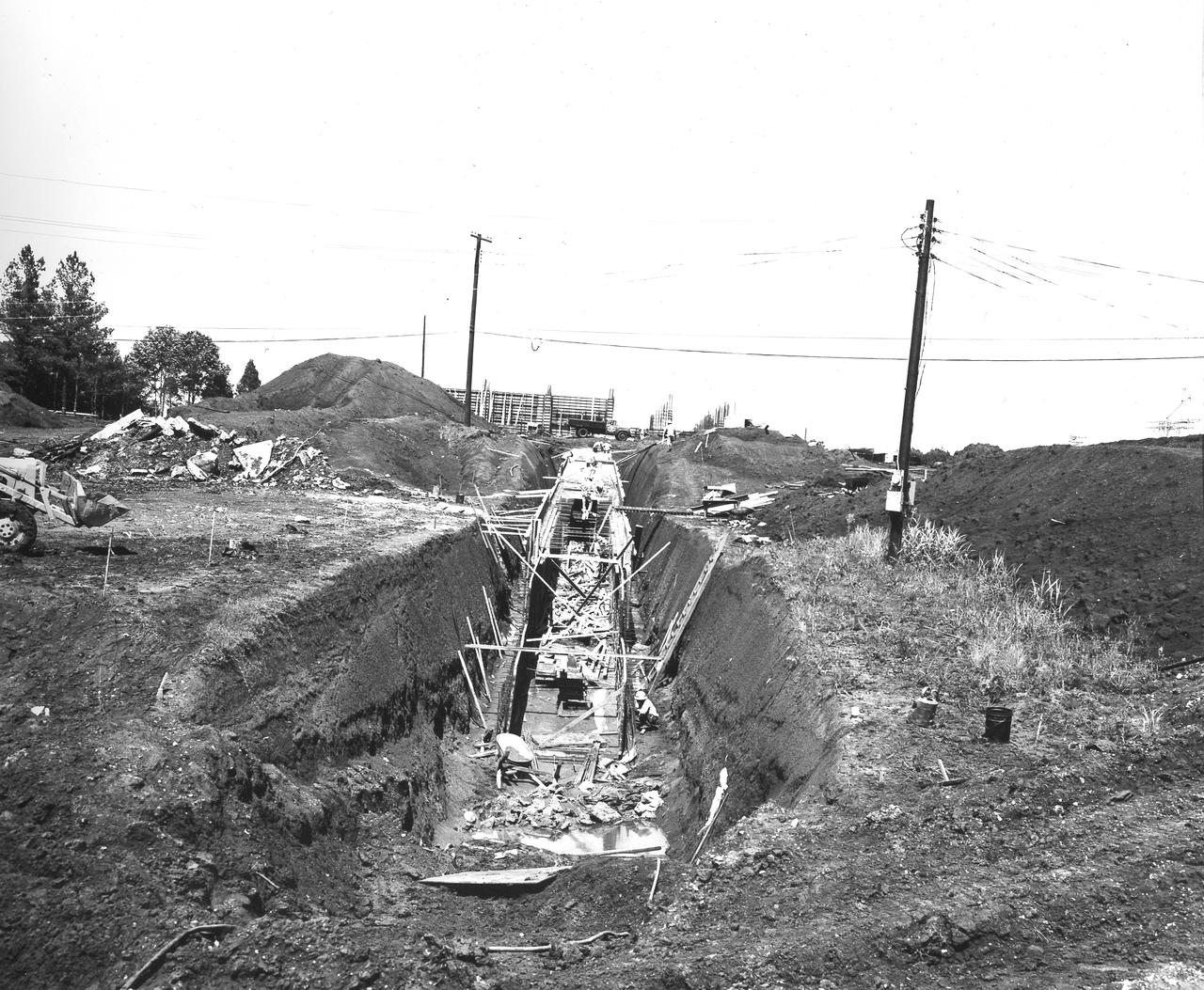
At its founding, the Marshall Space Flight Center (MSFC) inherited the Army’s Jupiter and Redstone test stands, but much larger facilities were needed for the giant stages of the Saturn V. From 1960 to 1964, the existing stands were remodeled and a sizable new test area was developed. The new comprehensive test complex for propulsion and structural dynamics was unique within the nation and the free world, and they remain so today because they were constructed with foresight to meet the future as well as on going needs. Construction of the S-IC Static test stand complex began in 1961 in the west test area of MSFC, and was completed in 1964. The S-IC static test stand was designed to develop and test the 138-ft long and 33-ft diameter Saturn V S-IC first stage, or booster stage, weighing in at 280,000 pounds. Required to hold down the brute force of a 7,500,000-pound thrust produced by 5 F-1 engines, the S-IC static test stand was designed and constructed with the strength of hundreds of tons of steel and 12,000,000 pounds of cement, planted down to bedrock 40 feet below ground level. The foundation walls, constructed with concrete and steel, are 4 feet thick. The base structure consists of four towers with 40-foot-thick walls extending upward 144 feet above ground level. The structure was topped by a crane with a 135-foot boom. With the boom in the upright position, the stand was given an overall height of 405 feet, placing it among the highest structures in Alabama at the time. In addition to the stand itself, related facilities were constructed during this time. Built directly east of the test stand was the Block House, which served as the control center for the test stand. The two were connected by a narrow access tunnel which housed the cables for the controls. Construction of the tunnel is depicted in this photo taken June 13, 1962.
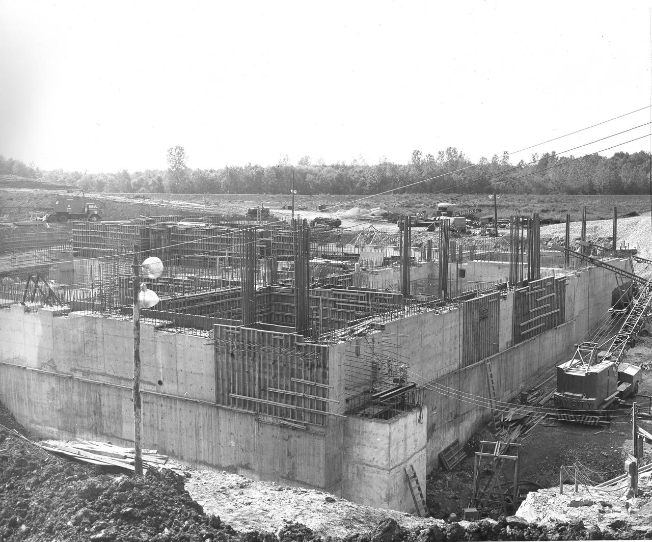
At its founding, the Marshall Space Flight Center (MSFC) inherited the Army’s Jupiter and Redstone test stands, but much larger facilities were needed for the giant stages of the Saturn V. From 1960 to 1964, the existing stands were remodeled and a sizable new test area was developed. The new comprehensive test complex for propulsion and structural dynamics was unique within the nation and the free world, and they remain so today because they were constructed with foresight to meet the future as well as on going needs. Construction of the S-IC Static test stand complex began in 1961 in the west test area of MSFC, and was completed in 1964. The S-IC static test stand was designed to develop and test the 138-ft long and 33-ft diameter Saturn V S-IC first stage, or booster stage, weighing in at 280,000 pounds. Required to hold down the brute force of a 7,500,000-pound thrust produced by 5 F-1 engines, the S-IC static test stand was designed and constructed with the strength of hundreds of tons of steel and 12,000,000 pounds of cement, planted down to bedrock 40 feet below ground level. The foundation walls, constructed with concrete and steel, are 4 feet thick. The base structure consists of four towers with 40-foot-thick walls extending upward 144 feet above ground level. The structure was topped by a crane with a 135-foot boom. With the boom in the upright position, the stand was given an overall height of 405 feet, placing it among the highest structures in Alabama at the time. In addition to the stand itself, related facilities were constructed during this time. Built directly east of the test stand was the Block House, which served as the control center for the test stand. The two were connected by a narrow access tunnel which housed the cables for the controls. This construction photo taken August 17, 1962 depicts a back side view of the Block House.
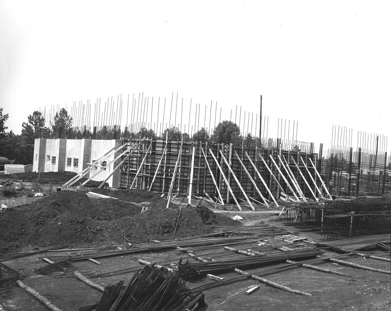
At its founding, the Marshall Space Flight Center (MSFC) inherited the Army’s Jupiter and Redstone test stands, but much larger facilities were needed for the giant stages of the Saturn V. From 1960 to 1964, the existing stands were remodeled and a sizable new test area was developed. The new comprehensive test complex for propulsion and structural dynamics was unique within the nation and the free world, and they remain so today because they were constructed with foresight to meet the future as well as on going needs. Construction of the S-IC Static test stand complex began in 1961 in the west test area of MSFC, and was completed in 1964. The S-IC static test stand was designed to develop and test the 138-ft long and 33-ft diameter Saturn V S-IC first stage, or booster stage, weighing in at 280,000 pounds. Required to hold down the brute force of a 7,500,000-pound thrust produced by 5 F-1 engines, the S-IC static test stand was designed and constructed with the strength of hundreds of tons of steel and 12,000,000 pounds of cement, planted down to bedrock 40 feet below ground level. The foundation walls, constructed with concrete and steel, are 4 feet thick. The base structure consists of four towers with 40-foot-thick walls extending upward 144 feet above ground level. The structure was topped by a crane with a 135-foot boom. With the boom in the upright position, the stand was given an overall height of 405 feet, placing it among the highest structures in Alabama at the time. In addition to the stand itself, related facilities were constructed during this time. Built directly east of the test stand was the Block House, which served as the control center for the test stand. The two were connected by a narrow access tunnel which housed the cables for the controls. This construction photo taken July 3, 1962 depicts the Block House with a portion of its concrete walls poured and exposed while many are still in the forms stage.
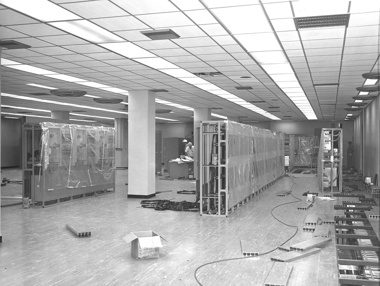
At its founding, the Marshall Space Flight Center (MSFC) inherited the Army’s Jupiter and Redstone test stands, but much larger facilities were needed for the giant stages of the Saturn V. From 1960 to 1964, the existing stands were remodeled and a sizable new test area was developed. The new comprehensive test complex for propulsion and structural dynamics was unique within the nation and the free world, and they remain so today because they were constructed with foresight to meet the future as well as on going needs. Construction of the S-IC Static test stand complex began in 1961 in the west test area of MSFC, and was completed in 1964. The S-IC static test stand was designed to develop and test the 138-ft long and 33-ft diameter Saturn V S-IC first stage, or booster stage, weighing in at 280,000 pounds. Required to hold down the brute force of a 7,500,000-pound thrust produced by 5 F-1 engines, the S-IC static test stand was designed and constructed with the strength of hundreds of tons of steel and 12,000,000 pounds of cement, planted down to bedrock 40 feet below ground level. The foundation walls, constructed with concrete and steel, are 4 feet thick. The base structure consists of four towers with 40-foot-thick walls extending upward 144 feet above ground level. The structure was topped by a crane with a 135-foot boom. With the boom in the upright position, the stand was given an overall height of 405 feet, placing it among the highest structures in Alabama at the time. In addition to the stand itself, related facilities were constructed during this time. Built directly east of the test stand was the Block House, which served as the control center for the test stand. The two were connected by a narrow access tunnel which housed the cables for the controls. This photograph, taken August 12, 1963, offers a view of the Block House interior.
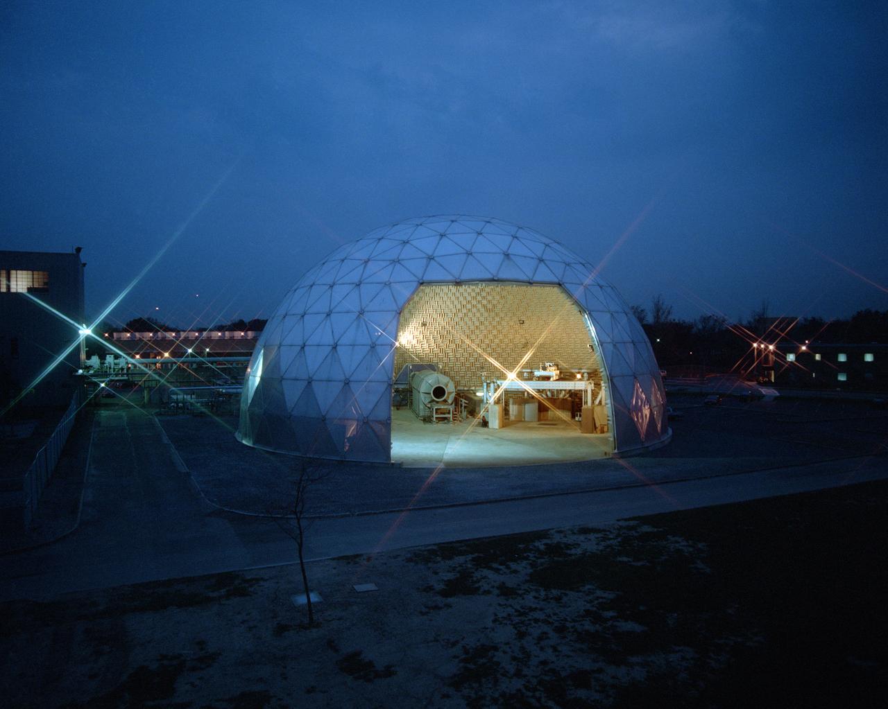
Modern jet engines are loud, but they used to be much louder. NASA’s Glenn Research Center has been at the forefront of the nation’s efforts to reduce aircraft engine noise for over 70 years. During this time, the center has built an array of test facilities to carry out this work, culminating in the Aero-Acoustic Propulsion Laboratory (AAPL), a world-class noise-reduction research facility. The AAPL, referred to as “the dome,” contains multiple test rigs enclosed in a large, echo-free chamber. The unique 130-foot diameter and 65-foot-high hemispherical structure stands out on Glenn’s campus. Its triangular sections make it appear like a golf ball rising from the ground. The interior is covered in spiky, fiberglass sound-dampening wedges and an overhead array of microphones that capture engine noise data.
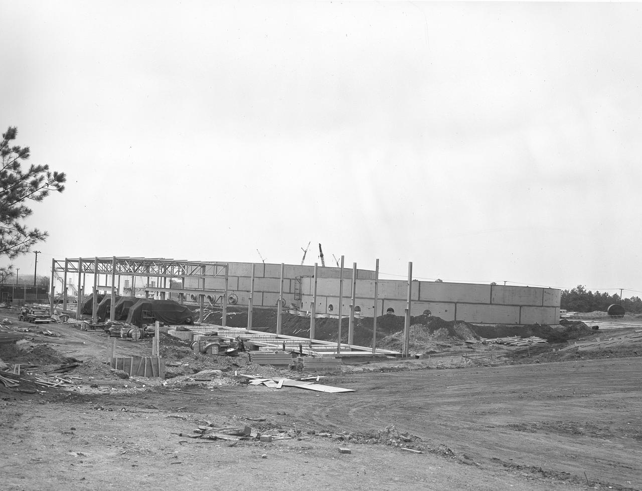
At its founding, the Marshall Space Flight Center (MSFC) inherited the Army’s Jupiter and Redstone test stands, but much larger facilities were needed for the giant stages of the Saturn V. From 1960 to 1964, the existing stands were remodeled and a sizable new test area was developed. The new comprehensive test complex for propulsion and structural dynamics was unique within the nation and the free world, and they remain so today because they were constructed with foresight to meet the future as well as on going needs. Construction of the S-IC Static test stand complex began in 1961 in the west test area of MSFC, and was completed in 1964. The S-IC static test stand was designed to develop and test the 138-ft long and 33-ft diameter Saturn V S-IC first stage, or booster stage, weighing in at 280,000 pounds. Required to hold down the brute force of a 7,500,000-pound thrust produced by 5 F-1 engines, the S-IC static test stand was designed and constructed with the strength of hundreds of tons of steel and 12,000,000 pounds of cement, planted down to bedrock 40 feet below ground level. The foundation walls, constructed with concrete and steel, are 4 feet thick. The base structure consists of four towers with 40-foot-thick walls extending upward 144 feet above ground level. The structure was topped by a crane with a 135-foot boom. With the boom in the upright position, the stand was given an overall height of 405 feet, placing it among the highest structures in Alabama at the time. In addition to the stand itself, related facilities were constructed during this time. Built to the northeast of the stand was a newly constructed Pump House. Its function was to provide water to the stand to prevent melting damage during testing. The water was sprayed through small holes in the stand’s 1900 ton flame deflector at the rate of 320,000 gallons per minute. This close up photograph, taken September 5, 1963, shows the ground level frame work for the Pump House and its massive round water storage tanks.
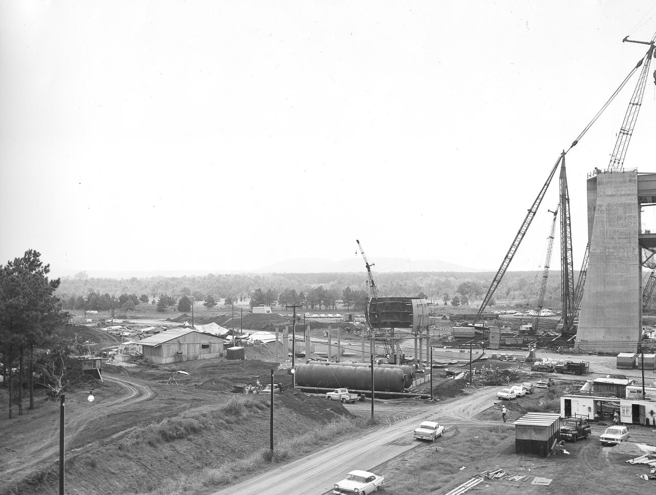
At its founding, the Marshall Space Flight Center (MSFC) inherited the Army’s Jupiter and Redstone test stands, but much larger facilities were needed for the giant stages of the Saturn V. From 1960 to 1964, the existing stands were remodeled and a sizable new test area was developed. The new comprehensive test complex for propulsion and structural dynamics was unique within the nation and the free world, and they remain so today because they were constructed with foresight to meet the future as well as on going needs. Construction of the S-IC Static test stand complex began in 1961 in the west test area of MSFC, and was completed in 1964. The S-IC static test stand was designed to develop and test the 138-ft long and 33-ft diameter Saturn V S-IC first stage, or booster stage, weighing in at 280,000 pounds. Required to hold down the brute force of a 7,500,000-pound thrust produced by 5 F-1 engines, the S-IC static test stand was designed and constructed with the strength of hundreds of tons of steel and 12,000,000 pounds of cement, planted down to bedrock 40 feet below ground level. The foundation walls, constructed with concrete and steel, are 4 feet thick. The base structure consists of four towers with 40-foot-thick walls extending upward 144 feet above ground level. The structure was topped by a crane with a 135-foot boom. With the boom in the upright position, the stand was given an overall height of 405 feet, placing it among the highest structures in Alabama at the time. In addition to the stand itself, related facilities were constructed during this time. In the center portion of this photograph, taken September 5, 1963, the spherical hydrogen storage tanks are being constructed. One of the massive tower legs of the S-IC test stand is visible to the far right.
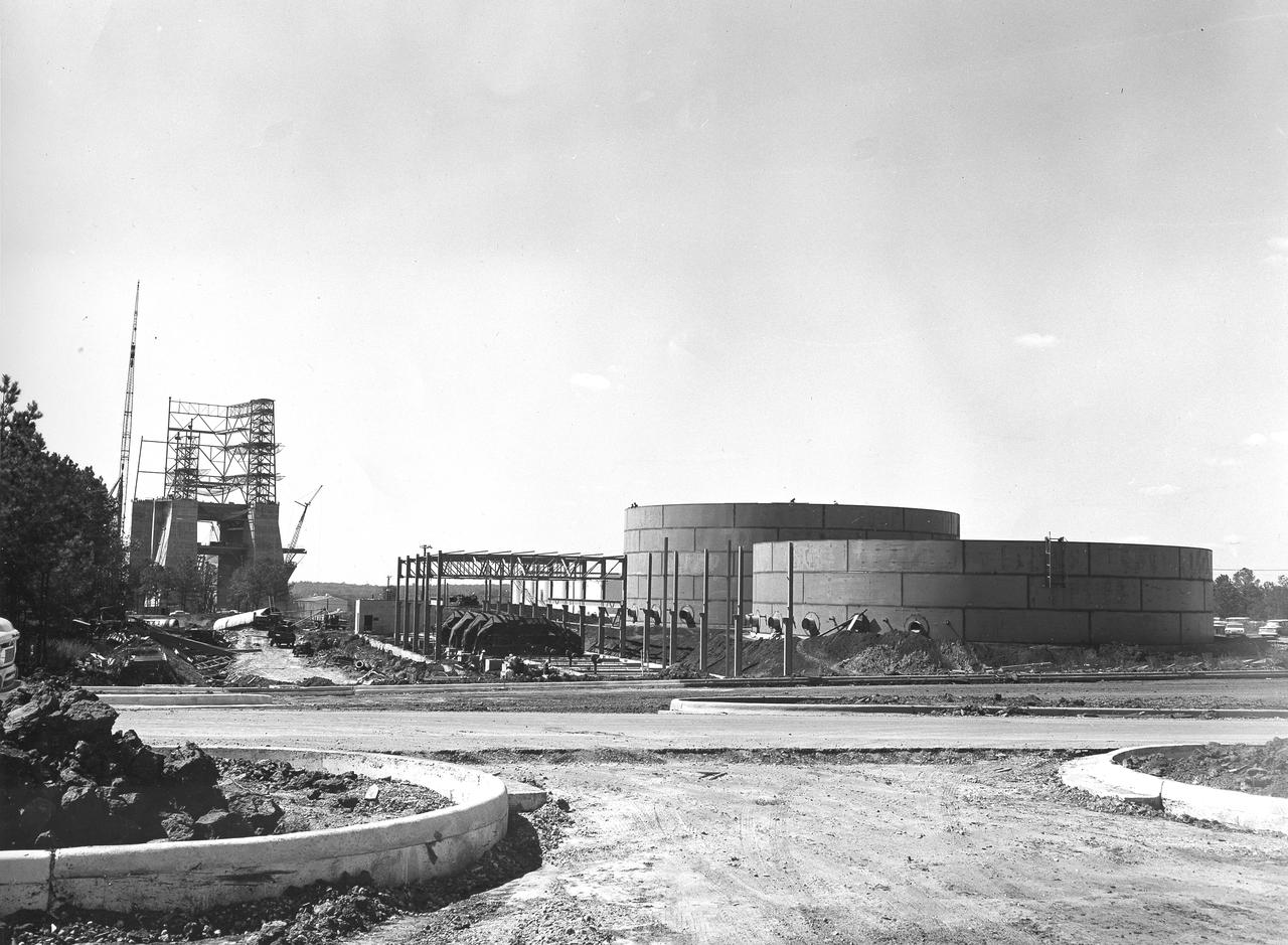
At its founding, the Marshall Space Flight Center (MSFC) inherited the Army’s Jupiter and Redstone test stands, but much larger facilities were needed for the giant stages of the Saturn V. From 1960 to 1964, the existing stands were remodeled and a sizable new test area was developed. The new comprehensive test complex for propulsion and structural dynamics was unique within the nation and the free world, and they remain so today because they were constructed with foresight to meet the future as well as on going needs. Construction of the S-IC Static test stand complex began in 1961 in the west test area of MSFC, and was completed in 1964. The S-IC static test stand was designed to develop and test the 138-ft long and 33-ft diameter Saturn V S-IC first stage, or booster stage, weighing in at 280,000 pounds. Required to hold down the brute force of a 7,500,000-pound thrust produced by 5 F-1 engines, the S-IC static test stand was designed and constructed with the strength of hundreds of tons of steel and 12,000,000 pounds of cement, planted down to bedrock 40 feet below ground level. The foundation walls, constructed with concrete and steel, are 4 feet thick. The base structure consists of four towers with 40-foot-thick walls extending upward 144 feet above ground level. The structure was topped by a crane with a 135-foot boom. With the boom in the upright position, the stand was given an overall height of 405 feet, placing it among the highest structures in Alabama at the time. In addition to the stand itself, related facilities were constructed during this time. Built to the northeast of the stand was a newly constructed Pump House. Its function was to provide water to the stand to prevent melting damage during testing. The water was sprayed through small holes in the stand’s 1900 ton flame deflector at the rate of 320,000 gallons per minute. This photograph, taken September 25, 1963, depicts the construction progress of the Pump House and massive round water tanks on the right.
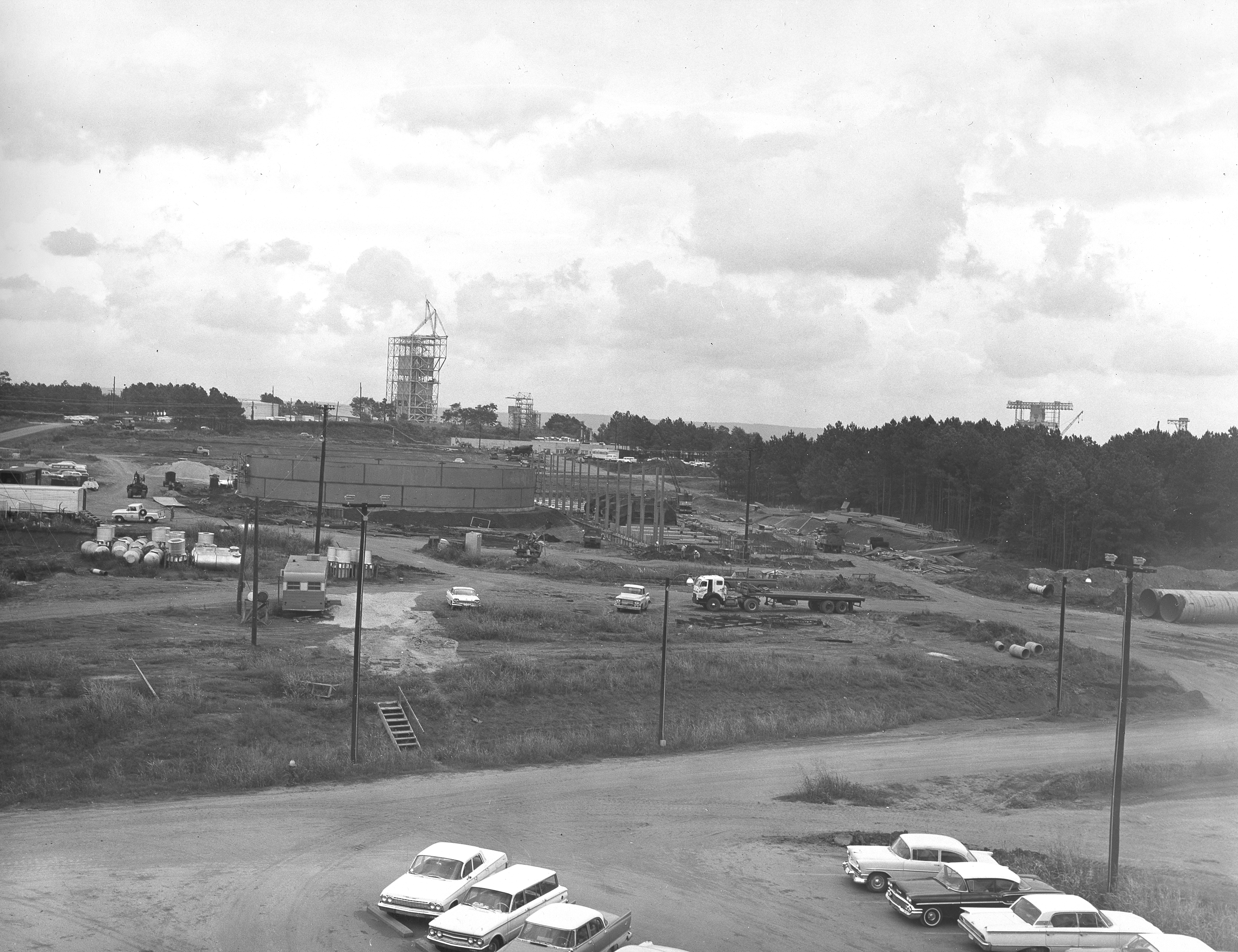
At its founding, the Marshall Space Flight Center (MSFC) inherited the Army’s Jupiter and Redstone test stands, but much larger facilities were needed for the giant stages of the Saturn V. From 1960 to 1964, the existing stands were remodeled and a sizable new test area was developed. The new comprehensive test complex for propulsion and structural dynamics was unique within the nation and the free world, and they remain so today because they were constructed with foresight to meet the future as well as on going needs. Construction of the S-IC Static test stand complex began in 1961 in the west test area of MSFC, and was completed in 1964. The S-IC static test stand was designed to develop and test the 138-ft long and 33-ft diameter Saturn V S-IC first stage, or booster stage, weighing in at 280,000 pounds. Required to hold down the brute force of a 7,500,000-pound thrust produced by 5 F-1 engines, the S-IC static test stand was designed and constructed with the strength of hundreds of tons of steel and 12,000,000 pounds of cement, planted down to bedrock 40 feet below ground level. The foundation walls, constructed with concrete and steel, are 4 feet thick. The base structure consists of four towers with 40-foot-thick walls extending upward 144 feet above ground level. The structure was topped by a crane with a 135-foot boom. With the boom in the upright position, the stand was given an overall height of 405 feet, placing it among the highest structures in Alabama at the time. In addition to the stand itself, related facilities were constructed during this time. Built to the northeast east was a newly constructed Pump House. Its function was to provide water to the stand to prevent melting damage during testing. The water was sprayed through small holes in the stand’s 1900 ton flame deflector at the rate of 320,000 gallons per minute. This photograph of the Pump House area was taken August 13, 1963. The massive round water storage tanks can be seen to the left of the Pump House.
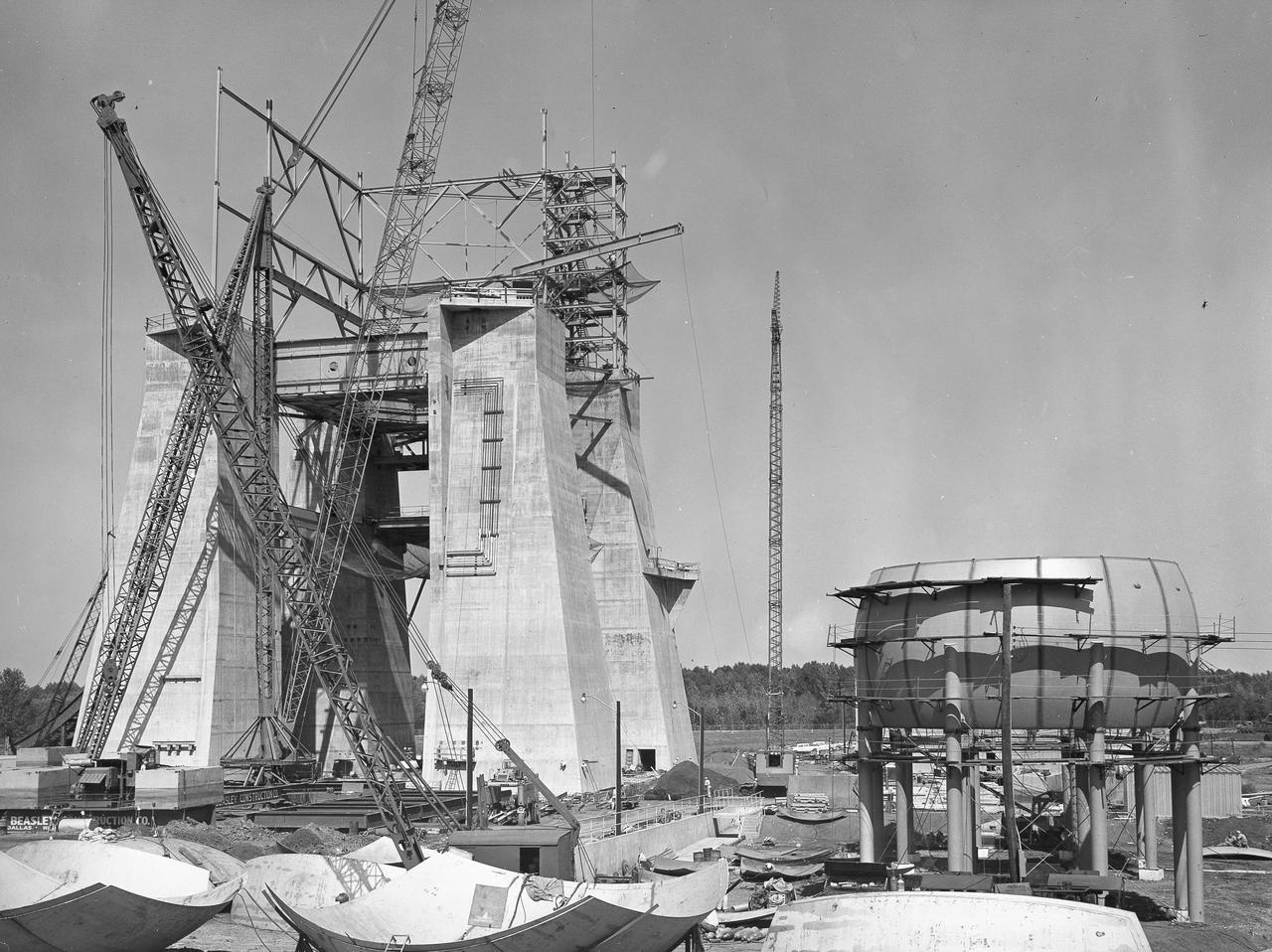
At its founding, the Marshall Space Flight Center (MSFC) inherited the Army’s Jupiter and Redstone test stands, but much larger facilities were needed for the giant stages of the Saturn V. From 1960 to 1964, the existing stands were remodeled and a sizable new test area was developed. The new comprehensive test complex for propulsion and structural dynamics was unique within the nation and the free world, and they remain so today because they were constructed with foresight to meet the future as well as on going needs. Construction of the S-IC Static test stand complex began in 1961 in the west test area of MSFC, and was completed in 1964. The S-IC static test stand was designed to develop and test the 138-ft long and 33-ft diameter Saturn V S-IC first stage, or booster stage, weighing in at 280,000 pounds. Required to hold down the brute force of a 7,500,000-pound thrust produced by 5 F-1 engines, the S-IC static test stand was designed and constructed with the strength of hundreds of tons of steel and 12,000,000 pounds of cement, planted down to bedrock 40 feet below ground level. The foundation walls, constructed with concrete and steel, are 4 feet thick. The base structure consists of four towers with 40-foot-thick walls extending upward 144 feet above ground level. The structure was topped by a crane with a 135-foot boom. With the boom in the upright position, the stand was given an overall height of 405 feet, placing it among the highest structures in Alabama at the time. In addition to the stand itself, related facilities were constructed during this time. This photograph taken September 18, 1963 shows a spherical hydrogen tank being constructed next to the S-IC test stand.
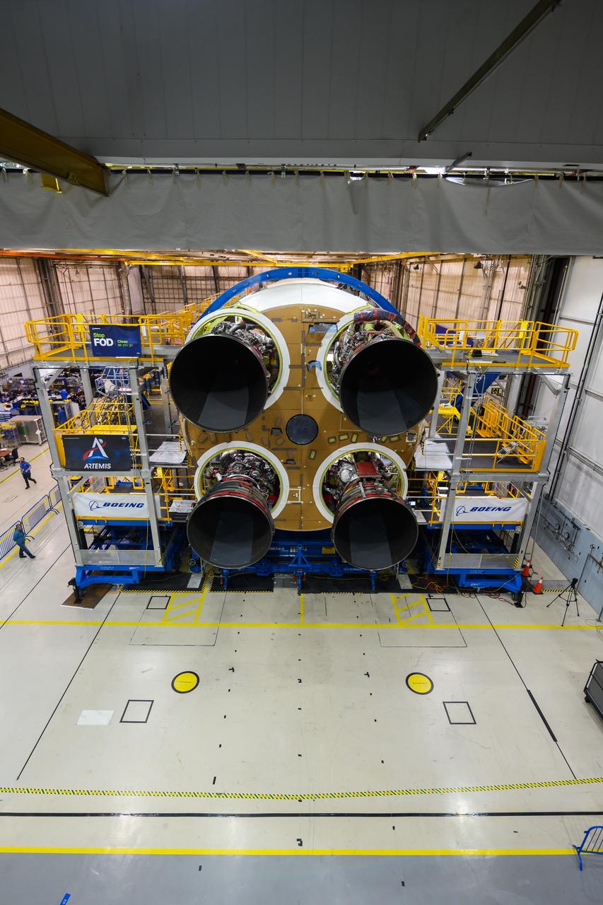
This photo shows all four RS-25 engines attached to the core stage for NASA’s Space Launch System rocket for the agency’s Artemis I mission to the Moon. To complete assembly of the rocket stage, engineers and technicians at NASA’s Michoud Assembly Facility in New Orleans are now integrating the propulsion and electrical systems within the structure. The completed core stage with all four RS-25 engines attached is the largest rocket stage NASA has built since the Saturn V stages for the Apollo Program that first sent Americans to the Moon. The stage, which includes two propellant tanks, provides more than 2 million pounds of thrust to send Artemis I to the Moon. Engineers and technicians attached the fourth RS-25 engine to the rocket stage Nov. 6 just one day after structurally mating the third engine. The first two RS-25 engines were structurally mated to the stage in October. After assembly is complete, crews will conduct an integrated functional test of flight computers, avionics and electrical systems that run throughout the 212-foot-tall core stage in preparation for its completion later this year. This testing is the first time all the flight avionics systems will be tested together to ensure the systems communicate with each other and will perform properly to control the rocket’s flight. Integration of the RS-25 engines to the recently completed core stage structure is a collaborative, multistep process for NASA and its partners Boeing, the core stage lead contractor, and Aerojet Rocketdyne, the RS-25 engines lead contractor. Offering more payload mass, volume capability and energy to speed missions through space, the SLS rocket, along with NASA’s Gateway in lunar orbit and Orion, is part of NASA’s backbone for deep space exploration and the Artemis lunar program. No other rocket is capable of carrying astronauts in Orion around the Moon in a single mission.
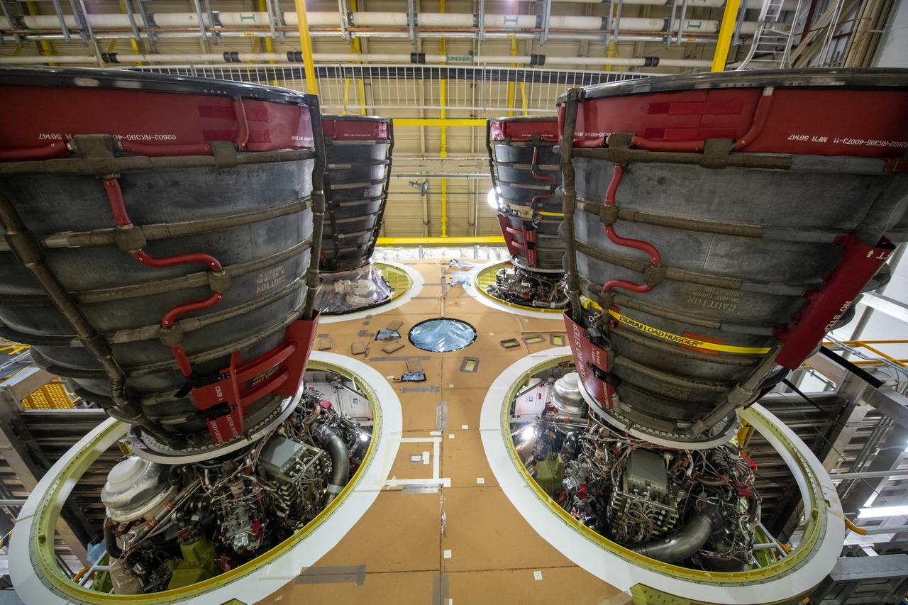
This photo shows all four RS-25 engines attached to the core stage for NASA’s Space Launch System rocket for the agency’s Artemis I mission to the Moon. To complete assembly of the rocket stage, engineers and technicians at NASA’s Michoud Assembly Facility in New Orleans are now integrating the propulsion and electrical systems within the structure. The completed core stage with all four RS-25 engines attached is the largest rocket stage NASA has built since the Saturn V stages for the Apollo Program that first sent Americans to the Moon. The stage, which includes two propellant tanks, provides more than 2 million pounds of thrust to send Artemis I to the Moon. Engineers and technicians attached the fourth RS-25 engine to the rocket stage Nov. 6 just one day after structurally mating the third engine. The first two RS-25 engines were structurally mated to the stage in October. After assembly is complete, crews will conduct an integrated functional test of flight computers, avionics and electrical systems that run throughout the 212-foot-tall core stage in preparation for its completion later this year. This testing is the first time all the flight avionics systems will be tested together to ensure the systems communicate with each other and will perform properly to control the rocket’s flight. Integration of the RS-25 engines to the recently completed core stage structure is a collaborative, multistep process for NASA and its partners Boeing, the core stage lead contractor, and Aerojet Rocketdyne, the RS-25 engines lead contractor. Offering more payload mass, volume capability and energy to speed missions through space, the SLS rocket, along with NASA’s Gateway in lunar orbit and Orion, is part of NASA’s backbone for deep space exploration and the Artemis lunar program. No other rocket is capable of carrying astronauts in Orion around the Moon in a single mission.
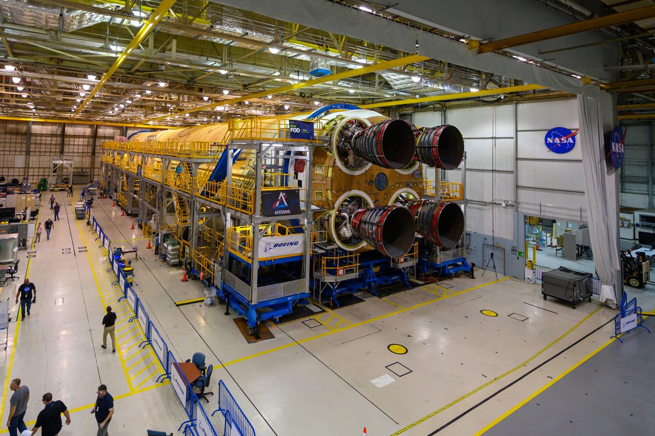
This photo shows all four RS-25 engines attached to the core stage for NASA’s Space Launch System rocket for the agency’s Artemis I mission to the Moon. To complete assembly of the rocket stage, engineers and technicians at NASA’s Michoud Assembly Facility in New Orleans are now integrating the propulsion and electrical systems within the structure. The completed core stage with all four RS-25 engines attached is the largest rocket stage NASA has built since the Saturn V stages for the Apollo Program that first sent Americans to the Moon. The stage, which includes two propellant tanks, provides more than 2 million pounds of thrust to send Artemis I to the Moon. Engineers and technicians attached the fourth RS-25 engine to the rocket stage Nov. 6 just one day after structurally mating the third engine. The first two RS-25 engines were structurally mated to the stage in October. After assembly is complete, crews will conduct an integrated functional test of flight computers, avionics and electrical systems that run throughout the 212-foot-tall core stage in preparation for its completion later this year. This testing is the first time all the flight avionics systems will be tested together to ensure the systems communicate with each other and will perform properly to control the rocket’s flight. Integration of the RS-25 engines to the recently completed core stage structure is a collaborative, multistep process for NASA and its partners Boeing, the core stage lead contractor, and Aerojet Rocketdyne, the RS-25 engines lead contractor. Offering more payload mass, volume capability and energy to speed missions through space, the SLS rocket, along with NASA’s Gateway in lunar orbit and Orion, is part of NASA’s backbone for deep space exploration and the Artemis lunar program. No other rocket is capable of carrying astronauts in Orion around the Moon in a single mission.
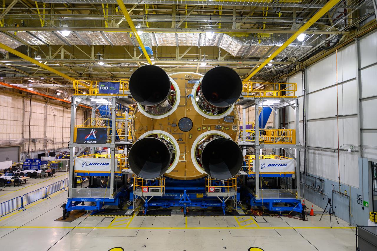
This photo shows all four RS-25 engines attached to the core stage for NASA’s Space Launch System rocket for the agency’s Artemis I mission to the Moon. To complete assembly of the rocket stage, engineers and technicians at NASA’s Michoud Assembly Facility in New Orleans are now integrating the propulsion and electrical systems within the structure. The completed core stage with all four RS-25 engines attached is the largest rocket stage NASA has built since the Saturn V stages for the Apollo Program that first sent Americans to the Moon. The stage, which includes two propellant tanks, provides more than 2 million pounds of thrust to send Artemis I to the Moon. Engineers and technicians attached the fourth RS-25 engine to the rocket stage Nov. 6 just one day after structurally mating the third engine. The first two RS-25 engines were structurally mated to the stage in October. After assembly is complete, crews will conduct an integrated functional test of flight computers, avionics and electrical systems that run throughout the 212-foot-tall core stage in preparation for its completion later this year. This testing is the first time all the flight avionics systems will be tested together to ensure the systems communicate with each other and will perform properly to control the rocket’s flight. Integration of the RS-25 engines to the recently completed core stage structure is a collaborative, multistep process for NASA and its partners Boeing, the core stage lead contractor, and Aerojet Rocketdyne, the RS-25 engines lead contractor. Offering more payload mass, volume capability and energy to speed missions through space, the SLS rocket, along with NASA’s Gateway in lunar orbit and Orion, is part of NASA’s backbone for deep space exploration and the Artemis lunar program. No other rocket is capable of carrying astronauts in Orion around the Moon in a single mission.
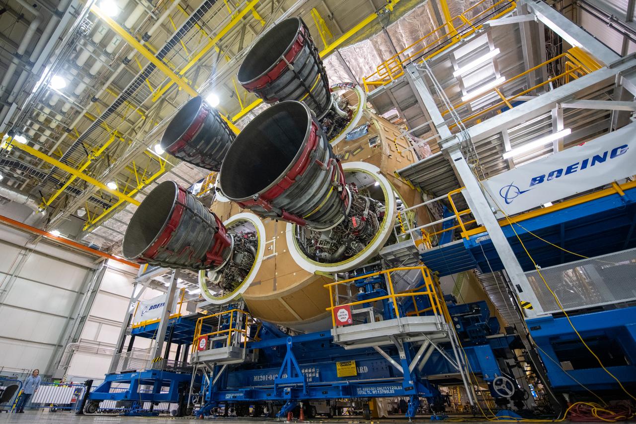
This photo shows all four RS-25 engines attached to the core stage for NASA’s Space Launch System rocket for the agency’s Artemis I mission to the Moon. To complete assembly of the rocket stage, engineers and technicians at NASA’s Michoud Assembly Facility in New Orleans are now integrating the propulsion and electrical systems within the structure. The completed core stage with all four RS-25 engines attached is the largest rocket stage NASA has built since the Saturn V stages for the Apollo Program that first sent Americans to the Moon. The stage, which includes two propellant tanks, provides more than 2 million pounds of thrust to send Artemis I to the Moon. Engineers and technicians attached the fourth RS-25 engine to the rocket stage Nov. 6 just one day after structurally mating the third engine. The first two RS-25 engines were structurally mated to the stage in October. After assembly is complete, crews will conduct an integrated functional test of flight computers, avionics and electrical systems that run throughout the 212-foot-tall core stage in preparation for its completion later this year. This testing is the first time all the flight avionics systems will be tested together to ensure the systems communicate with each other and will perform properly to control the rocket’s flight. Integration of the RS-25 engines to the recently completed core stage structure is a collaborative, multistep process for NASA and its partners Boeing, the core stage lead contractor, and Aerojet Rocketdyne, the RS-25 engines lead contractor. Offering more payload mass, volume capability and energy to speed missions through space, the SLS rocket, along with NASA’s Gateway in lunar orbit and Orion, is part of NASA’s backbone for deep space exploration and the Artemis lunar program. No other rocket is capable of carrying astronauts in Orion around the Moon in a single mission.
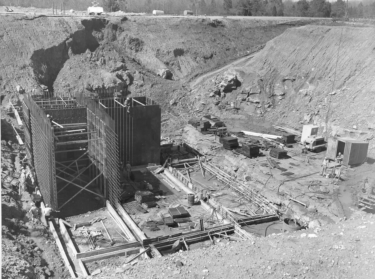
At its founding, the Marshall Space Flight Center (MSFC) inherited the Army’s Jupiter and Redstone test stands, but much larger facilities were needed for the giant stages of the Saturn V. From 1960 to 1964, the existing stands were remodeled and a sizable new test area was developed. The new comprehensive test complex for propulsion and structural dynamics was unique within the nation and the free world, and they remain so today because they were constructed with foresight to meet the future as well as on going needs. Construction of the S-IC Static test stand complex began in 1961 in the west test area of MSFC, and was completed in 1964. The S-IC static test stand was designed to develop and test the 138-ft long and 33-ft diameter Saturn V S-IC first stage, or booster stage, weighing in at 280,000 pounds. Required to hold down the brute force of a 7,500,000-pound thrust produced by 5 F-1 engines, the S-IC static test stand was designed and constructed with the strength of hundreds of tons of steel and 12,000,000 pounds of cement, planted down to bedrock 40 feet below ground level. The foundation walls, constructed with concrete and steel, are 4 feet thick. The base structure consists of four towers with 40-foot-thick walls extending upward 144 feet above ground level. The structure was topped by a crane with a 135-foot boom. With the boom in the upright position, the stand was given an overall height of 405 feet, placing it among the highest structures in Alabama at the time. North of the massive S-IC test stand, the F-1 Engine test stand was built. Designed to assist in the development of the F-1 Engine, the F-1 test stand is a vertical engine firing test stand, 239 feet in elevation and 4,600 square feet in area at the base. Capability was provided for static firing of 1.5 million pounds of thrust using liquid oxygen and kerosene. Like the S-IC stand, the foundation of the F-1 stand is keyed into the bedrock approximately 40 feet below grade. This photo, taken April 4, 1963 depicts the construction of the F-1 test stand foundation walls.
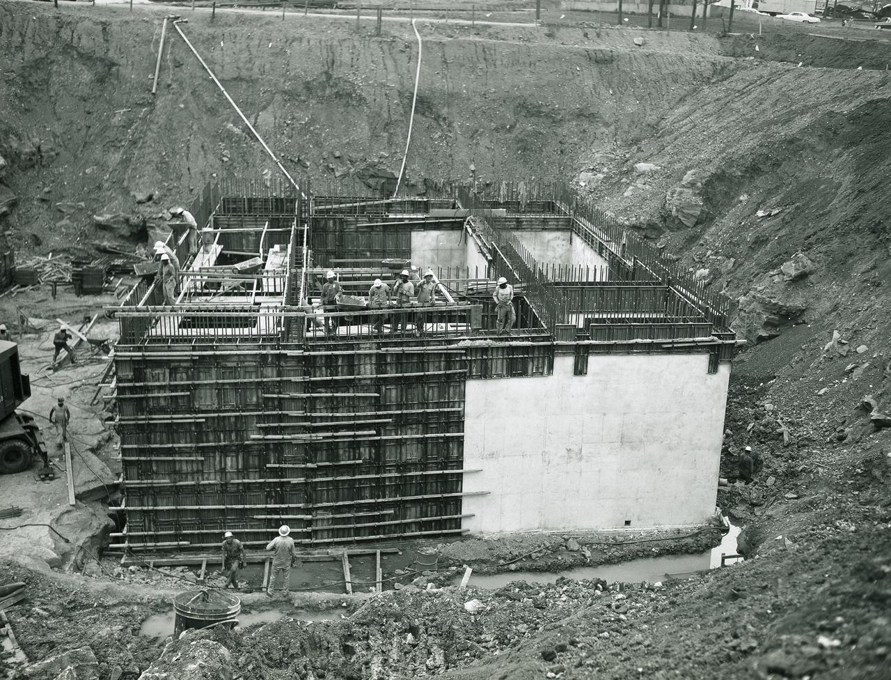
At its founding, the Marshall Space Flight Center (MSFC) inherited the Army’s Jupiter and Redstone test stands, but much larger facilities were needed for the giant stages of the Saturn V. From 1960 to 1964, the existing stands were remodeled and a sizable new test area was developed. The new comprehensive test complex for propulsion and structural dynamics was unique within the nation and the free world, and they remain so today because they were constructed with foresight to meet the future as well as on going needs. Construction of the S-IC Static test stand complex began in 1961 in the west test area of MSFC, and was completed in 1964. The S-IC static test stand was designed to develop and test the 138-ft long and 33-ft diameter Saturn V S-IC first stage, or booster stage, weighing in at 280,000 pounds. Required to hold down the brute force of a 7,500,000-pound thrust produced by 5 F-1 engines, the S-IC static test stand was designed and constructed with the strength of hundreds of tons of steel and 12,000,000 pounds of cement, planted down to bedrock 40 feet below ground level. The foundation walls, constructed with concrete and steel, are 4 feet thick. The base structure consists of four towers with 40-foot-thick walls extending upward 144 feet above ground level. The structure was topped by a crane with a 135-foot boom. With the boom in the upright position, the stand was given an overall height of 405 feet, placing it among the highest structures in Alabama at the time. North of the massive S-IC test stand, the F-1 Engine test stand was built. Designed to assist in the development of the F-1 Engine, the F-1 test stand is a vertical engine firing test stand, 239 feet in elevation and 4,600 square feet in area at the base. Capability was provided for static firing of 1.5 million pounds of thrust using liquid oxygen and kerosene. Like the S-IC stand, the foundation of the F-1 stand is keyed into the bedrock approximately 40 feet below grade. This photo, taken April 17, 1963 depicts the construction of the F-1 test stand foundation walls.
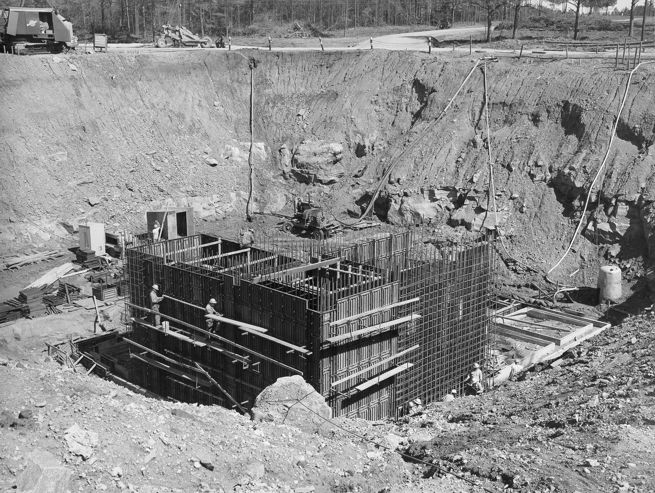
At its founding, the Marshall Space Flight Center (MSFC) inherited the Army’s Jupiter and Redstone test stands, but much larger facilities were needed for the giant stages of the Saturn V. From 1960 to 1964, the existing stands were remodeled and a sizable new test area was developed. The new comprehensive test complex for propulsion and structural dynamics was unique within the nation and the free world, and they remain so today because they were constructed with foresight to meet the future as well as on going needs. Construction of the S-IC Static test stand complex began in 1961 in the west test area of MSFC, and was completed in 1964. The S-IC static test stand was designed to develop and test the 138-ft long and 33-ft diameter Saturn V S-IC first stage, or booster stage, weighing in at 280,000 pounds. Required to hold down the brute force of a 7,500,000-pound thrust produced by 5 F-1 engines, the S-IC static test stand was designed and constructed with the strength of hundreds of tons of steel and 12,000,000 pounds of cement, planted down to bedrock 40 feet below ground level. The foundation walls, constructed with concrete and steel, are 4 feet thick. The base structure consists of four towers with 40-foot-thick walls extending upward 144 feet above ground level. The structure was topped by a crane with a 135-foot boom. With the boom in the upright position, the stand was given an overall height of 405 feet, placing it among the highest structures in Alabama at the time. North of the massive S-IC test stand, the F-1 Engine test stand was built. Designed to assist in the development of the F-1 Engine, the F-1 test stand is a vertical engine firing test stand, 239 feet in elevation and 4,600 square feet in area at the base. Capability was provided for static firing of 1.5 million pounds of thrust using liquid oxygen and kerosene. Like the S-IC stand, the foundation of the F-1 stand is keyed into the bedrock approximately 40 feet below grade. This photo, taken April 4, 1963 depicts the construction of the F-1 test stand foundation walls.
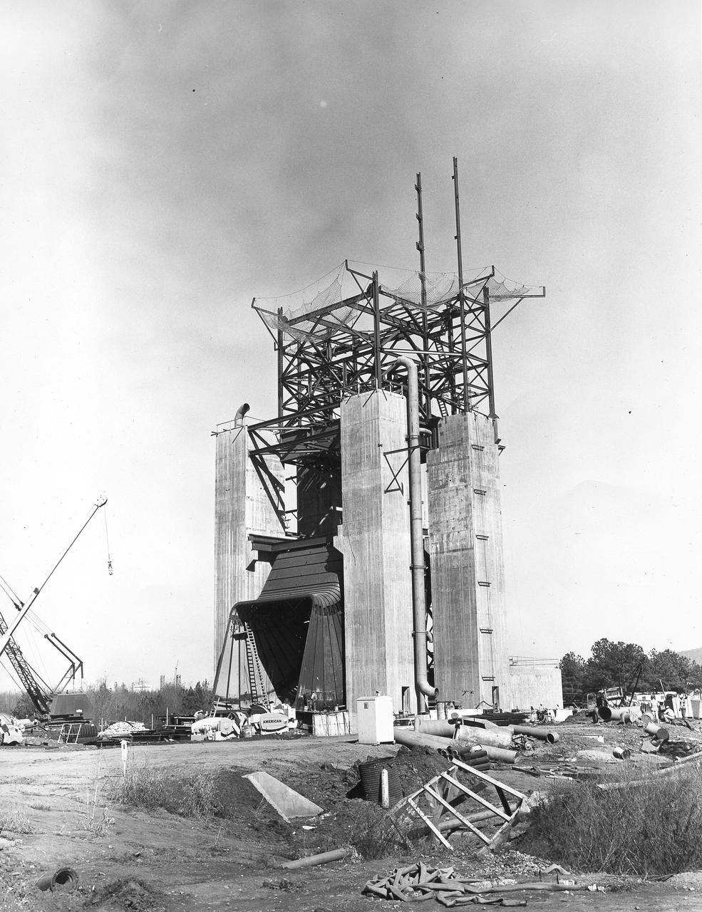
At its founding, the Marshall Space Flight Center (MSFC) inherited the Army’s Jupiter and Redstone test stands, but much larger facilities were needed for the giant stages of the Saturn V. From 1960 to 1964, the existing stands were remodeled and a sizable new test area was developed. The new comprehensive test complex for propulsion and structural dynamics was unique within the nation and the free world, and they remain so today because they were constructed with foresight to meet the future as well as on going needs. Construction of the S-IC Static test stand complex began in 1961 in the west test area of MSFC, and was completed in 1964. The S-IC static test stand was designed to develop and test the 138-ft long and 33-ft diameter Saturn V S-IC first stage, or booster stage, weighing in at 280,000 pounds. Required to hold down the brute force of a 7,500,000-pound thrust produced by 5 F-1 engines, the S-IC static test stand was designed and constructed with the strength of hundreds of tons of steel and 12,000,000 pounds of cement, planted down to bedrock 40 feet below ground level. The foundation walls, constructed with concrete and steel, are 4 feet thick. The base structure consists of four towers with 40-foot-thick walls extending upward 144 feet above ground level. The structure was topped by a crane with a 135-foot boom. With the boom in the upright position, the stand was given an overall height of 405 feet, placing it among the highest structures in Alabama at the time. North of the massive S-IC test stand, the F-1 Engine test stand was built. Designed to assist in the development of the F-1 Engine, the F-1 test stand is a vertical engine firing test stand, 239 feet in elevation and 4,600 square feet in area at the base. Capability was provided for static firing of 1.5 million pounds of thrust using liquid oxygen and kerosene. Like the S-IC stand, the foundation of the F-1 stand is keyed into the bedrock approximately 40 feet below grade. This photo shows the progress of the F-1 Test Stand as of November 20, 1963.
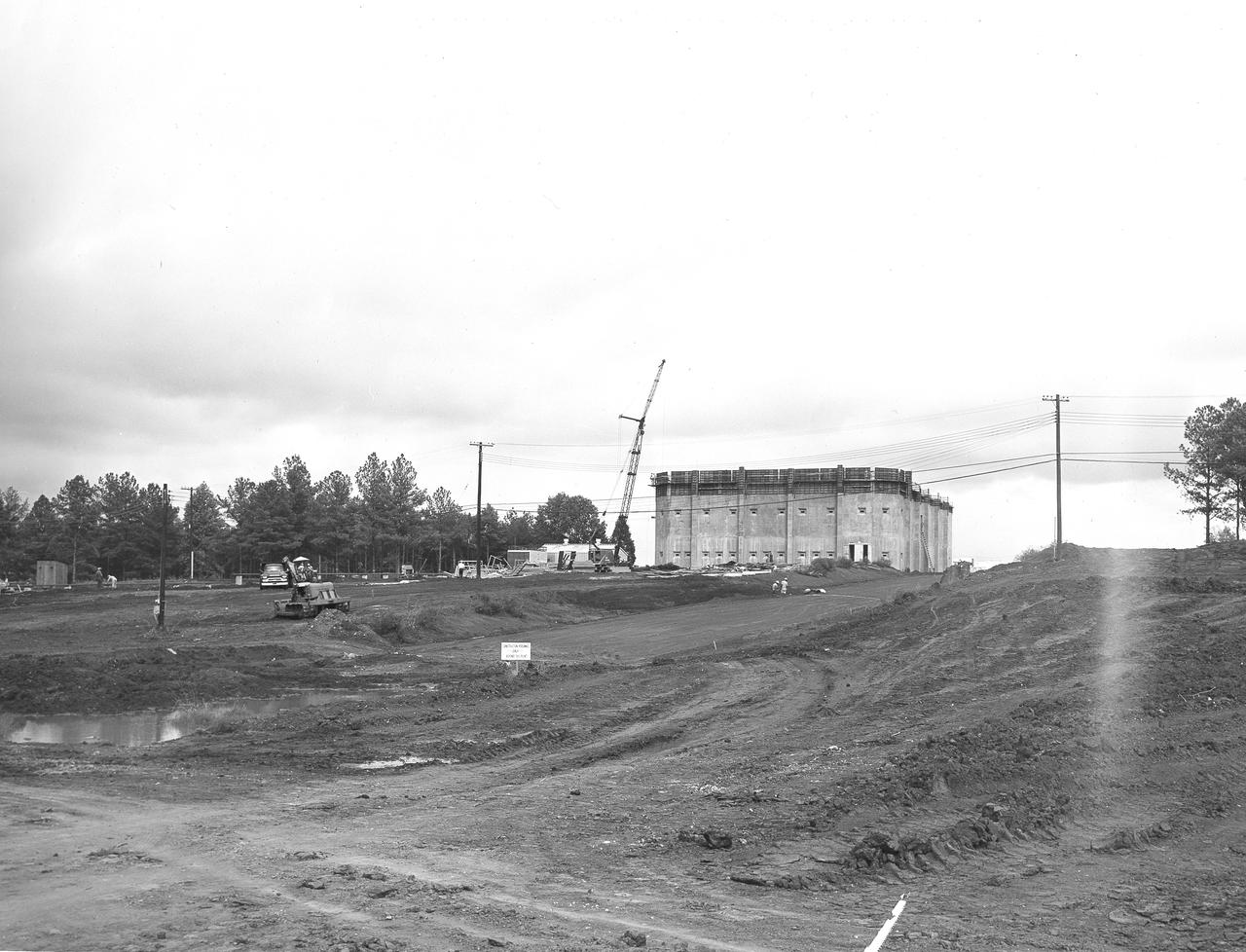
At its founding, the Marshall Space Flight Center (MSFC) inherited the Army’s Jupiter and Redstone test stands, but much larger facilities were needed for the giant stages of the Saturn V. From 1960 to 1964, the existing stands were remodeled and a sizable new test area was developed. The new comprehensive test complex for propulsion and structural dynamics was unique within the nation and the free world, and they remain so today because they were constructed with foresight to meet the future as well as on going needs. Construction of the S-IC Static test stand complex began in 1961 in the west test area of MSFC, and was completed in 1964. The S-IC static test stand was designed to develop and test the 138-ft long and 33-ft diameter Saturn V S-IC first stage, or booster stage, weighing in at 280,000 pounds. Required to hold down the brute force of a 7,500,000-pound thrust produced by 5 F-1 engines, the S-IC static test stand was designed and constructed with the strength of hundreds of tons of steel and 12,000,000 pounds of cement, planted down to bedrock 40 feet below ground level. The foundation walls, constructed with concrete and steel, are 4 feet thick. The base structure consists of four towers with 40-foot-thick walls extending upward 144 feet above ground level. The structure was topped by a crane with a 135-foot boom. With the boom in the upright position, the stand was given an overall height of 405 feet, placing it among the highest structures in Alabama at the time. Built directly east of the test stand was the Block House, which served as the control center for the test stand. The two were connected by a narrow access tunnel which housed the cables for the controls. This construction photo, taken October 8, 1962, depicts a front view of the Block House nearing completion.
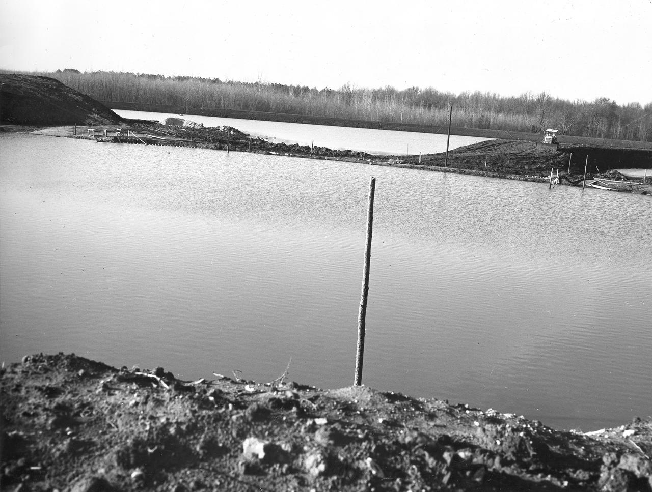
At its founding, the Marshall Space Flight Center (MSFC) inherited the Army’s Jupiter and Redstone test stands, but much larger facilities were needed for the giant stages of the Saturn V. From 1960 to 1964, the existing stands were remodeled and a sizable new test area was developed. The new comprehensive test complex for propulsion and structural dynamics was unique within the nation and the free world, and they remain so today because they were constructed with foresight to meet the future as well as on going needs. Construction of the S-IC Static test stand complex began in 1961 in the west test area of MSFC, and was completed in 1964. The S-IC static test stand was designed to develop and test the 138-ft long and 33-ft diameter Saturn V S-IC first stage, or booster stage, weighing in at 280,000 pounds. Required to hold down the brute force of a 7,500,000-pound thrust produced by 5 F-1 engines, the S-IC static test stand was designed and constructed with the strength of hundreds of tons of steel and 12,000,000 pounds of cement, planted down to bedrock 40 feet below ground level. The foundation walls, constructed with concrete and steel, are 4 feet thick. The base structure consists of four towers with 40-foot-thick walls extending upward 144 feet above ground level. The structure was topped by a crane with a 135-foot boom. With the boom in the upright position, the stand was given an overall height of 405 feet, placing it among the highest structures in Alabama at the time. Construction of the S-IC test stand came to a halt at the end of September as the determination was made that the Saturn booster size had to be increased. As a result, the stand had to be modified. With construction delayed, and pumps turned off, this photo, taken December 22, 1961, shows danger signs posted around the abandoned site with floods nearing the top. The flooding was caused by the disturbance of a natural spring months prior during the excavation of the site.

At its founding, the Marshall Space Flight Center (MSFC) inherited the Army’s Jupiter and Redstone test stands, but much larger facilities were needed for the giant stages of the Saturn V. From 1960 to 1964, the existing stands were remodeled and a sizable new test area was developed. The new comprehensive test complex for propulsion and structural dynamics was unique within the nation and the free world, and they remain so today because they were constructed with foresight to meet the future as well as on going needs. Construction of the S-IC Static test stand complex began in 1961 in the west test area of MSFC, and was completed in 1964. The S-IC static test stand was designed to develop and test the 138-ft long and 33-ft diameter Saturn V S-IC first stage, or booster stage, weighing in at 280,000 pounds. Required to hold down the brute force of a 7,500,000-pound thrust produced by 5 F-1 engines, the S-IC static test stand was designed and constructed with the strength of hundreds of tons of steel and 12,000,000 pounds of cement, planted down to bedrock 40 feet below ground level. The foundation walls, constructed with concrete and steel, are 4 feet thick. The base structure consists of four towers with 40-foot-thick walls extending upward 144 feet above ground level. The structure was topped by a crane with a 135-foot boom. With the boom in the upright position, the stand was given an overall height of 405 feet, placing it among the highest structures in Alabama at the time. In this photo, taken July 21, 1961, workers can be seen inside the test stand work area clearing the site.
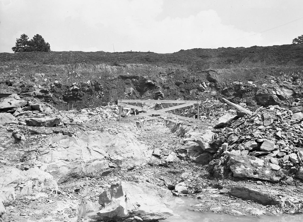
At its founding, the Marshall Space Flight Center (MSFC) inherited the Army’s Jupiter and Redstone test stands, but much larger facilities were needed for the giant stages of the Saturn V. From 1960 to 1964, the existing stands were remodeled and a sizable new test area was developed. The new comprehensive test complex for propulsion and structural dynamics was unique within the nation and the free world, and they remain so today because they were constructed with foresight to meet the future as well as on going needs. Construction of the S-IC Static test stand complex began in 1961 in the west test area of MSFC, and was completed in 1964. The S-IC static test stand was designed to develop and test the 138-ft long and 33-ft diameter Saturn V S-IC first stage, or booster stage, weighing in at 280,000 pounds. Required to hold down the brute force of a 7,500,000-pound thrust produced by 5 F-1 engines, the S-IC static test stand was designed and constructed with the strength of hundreds of tons of steel and 12,000,000 pounds of cement, planted down to bedrock 40 feet below ground level. The foundation walls, constructed with concrete and steel, are 4 feet thick. The base structure consists of four towers with 40-foot-thick walls extending upward 144 feet above ground level. The structure was topped by a crane with a 135-foot boom. With the boom in the upright position, the stand was given an overall height of 405 feet, placing it among the highest structures in Alabama at the time. This photo shows the construction progress of the S-IC test stand as of September 7, 1961.
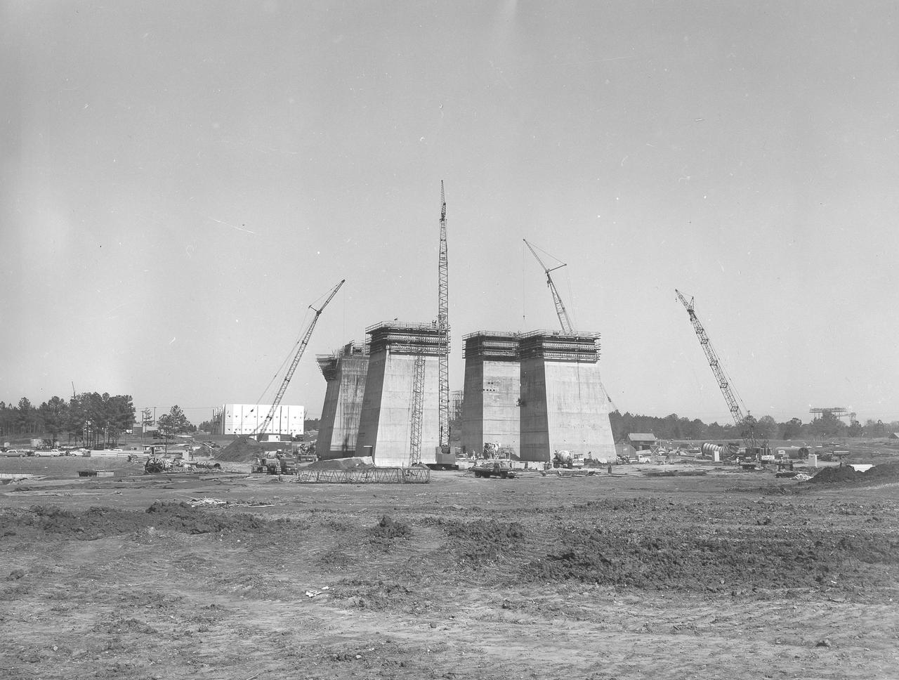
At its founding, the Marshall Space Flight Center (MSFC) inherited the Army’s Jupiter and Redstone test stands, but much larger facilities were needed for the giant stages of the Saturn V. From 1960 to 1964, the existing stands were remodeled and a sizable new test area was developed. The new comprehensive test complex for propulsion and structural dynamics was unique within the nation and the free world, and they remain so today because they were constructed with foresight to meet the future as well as on going needs. Construction of the S-IC Static test stand complex began in 1961 in the west test area of MSFC, and was completed in 1964. The S-IC static test stand was designed to develop and test the 138-ft long and 33-ft diameter Saturn V S-IC first stage, or booster stage, weighing in at 280,000 pounds. Required to hold down the brute force of a 7,500,000-pound thrust produced by 5 F-1 engines, the S-IC static test stand was designed and constructed with the strength of hundreds of tons of steel and 12,000,000 pounds of cement, planted down to bedrock 40 feet below ground level. The foundation walls, constructed with concrete and steel, are 4 feet thick. The base structure consists of four towers with 40-foot-thick walls extending upward 144 feet above ground level. The structure was topped by a crane with a 135-foot boom. With the boom in the upright position, the stand was given an overall height of 405 feet, placing it among the highest structures in Alabama at the time. This photograph, taken April 4, 1963, gives a close up look at the ever-growing four towers of the S-IC Test Stand.