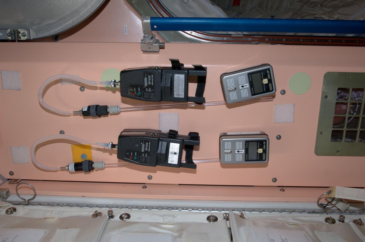
View of Canadian Space Agency (CSA) - CP SP402 Sampling Pump, in the Node 1. Photo was taken during Expedition 34.

Lying more than 110 million light-years away from Earth in the constellation of Antlia (The Air Pump) is the spiral galaxy IC 2560, shown here in an image from NASA/ESA Hubble Space Telescope. At this distance it is a relatively nearby spiral galaxy, and is part of the Antlia cluster — a group of over 200 galaxies held together by gravity. This cluster is unusual; unlike most other galaxy clusters, it appears to have no dominant galaxy within it. In this image, it is easy to spot IC 2560's spiral arms and barred structure. This spiral is what astronomers call a Seyfert-2 galaxy, a kind of spiral galaxy characterized by an extremely bright nucleus and very strong emission lines from certain elements — hydrogen, helium, nitrogen, and oxygen. The bright center of the galaxy is thought to be caused by the ejection of huge amounts of super-hot gas from the region around a central black hole. There is a story behind the naming of this quirky constellation — Antlia was originally named antlia pneumatica by French astronomer Abbé Nicolas Louis de Lacaille, in honor of the invention of the air pump in the 17th century. Credit: Hubble/European Space Agency and NASA <b><a href="http://www.nasa.gov/audience/formedia/features/MP_Photo_Guidelines.html" rel="nofollow">NASA image use policy.</a></b> <b><a href="http://www.nasa.gov/centers/goddard/home/index.html" rel="nofollow">NASA Goddard Space Flight Center</a></b> enables NASA’s mission through four scientific endeavors: Earth Science, Heliophysics, Solar System Exploration, and Astrophysics. Goddard plays a leading role in NASA’s accomplishments by contributing compelling scientific knowledge to advance the Agency’s mission. <b>Follow us on <a href="http://twitter.com/NASA_GoddardPix" rel="nofollow">Twitter</a></b> <b>Like us on <a href="http://www.facebook.com/pages/Greenbelt-MD/NASA-Goddard/395013845897?ref=tsd" rel="nofollow">Facebook</a></b> <b>Find us on <a href="http://instagram.com/nasagoddard?vm=grid" rel="nofollow">Instagram</a></b>
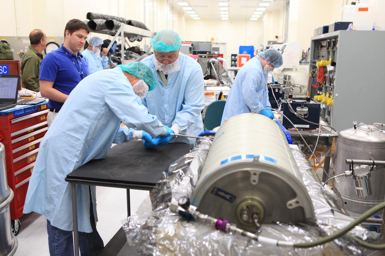
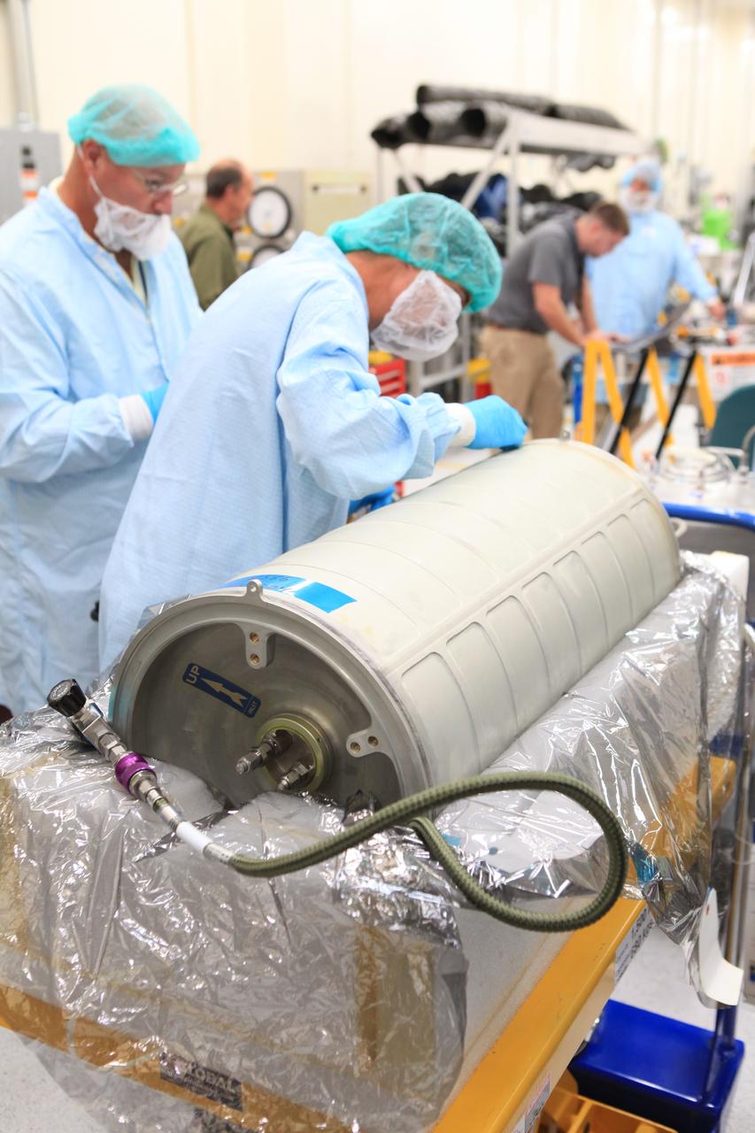
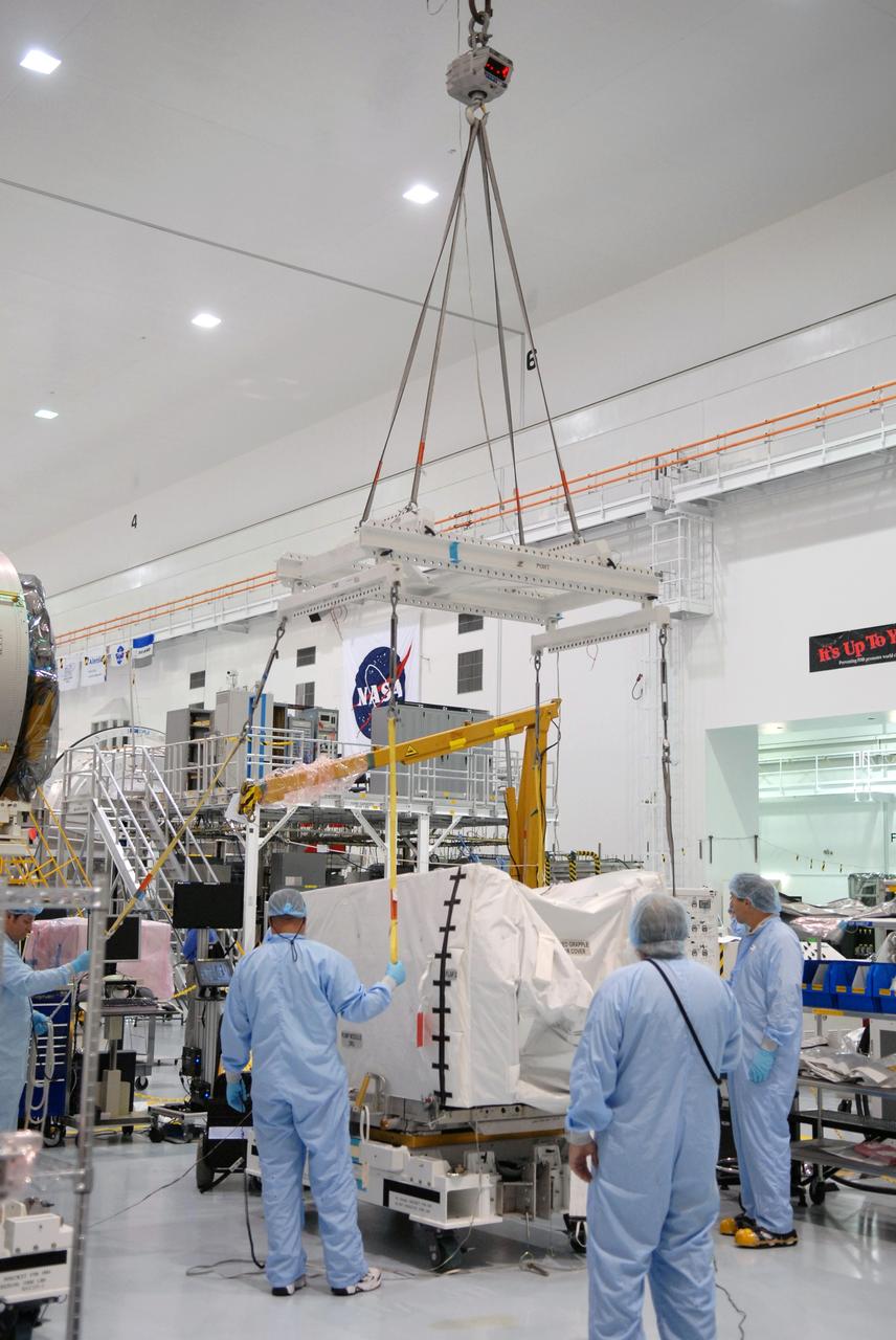
Inside the Space Station Processing Facility high bay at NASA's Kennedy Space Center in Florida, technicians work on the pump package assembly (PPA) on Aug. 30, 2018. The payload will be carried to the International Space Station on SpaceX's 16th Commercial Resupply Services mission. The PPA will be used to continuously drive the cooling water in the space station's thermal control system. The assembly includes a centrifuge pump, a fine filter and gas trap for pump protection, a coarse outlet filter, sensors, and an accumulator. The PPA also will provide a reservoir used for makeup of coolant if leakage occurred. CRS-16 is scheduled to launch to the space station later this year.
Inside the Space Station Processing Facility high bay at NASA's Kennedy Space Center in Florida, technicians work on the pump package assembly (PPA) on Aug. 30, 2018. The payload will be carried to the International Space Station on SpaceX's 16th Commercial Resupply Services mission. The PPA will be used to continuously drive the cooling water in the space station's thermal control system. The assembly includes a centrifuge pump, a fine filter and gas trap for pump protection, a coarse outlet filter, sensors, and an accumulator. The PPA also will provide a reservoir used for makeup of coolant if leakage occurred. CRS-16 is scheduled to launch to the space station later this year.
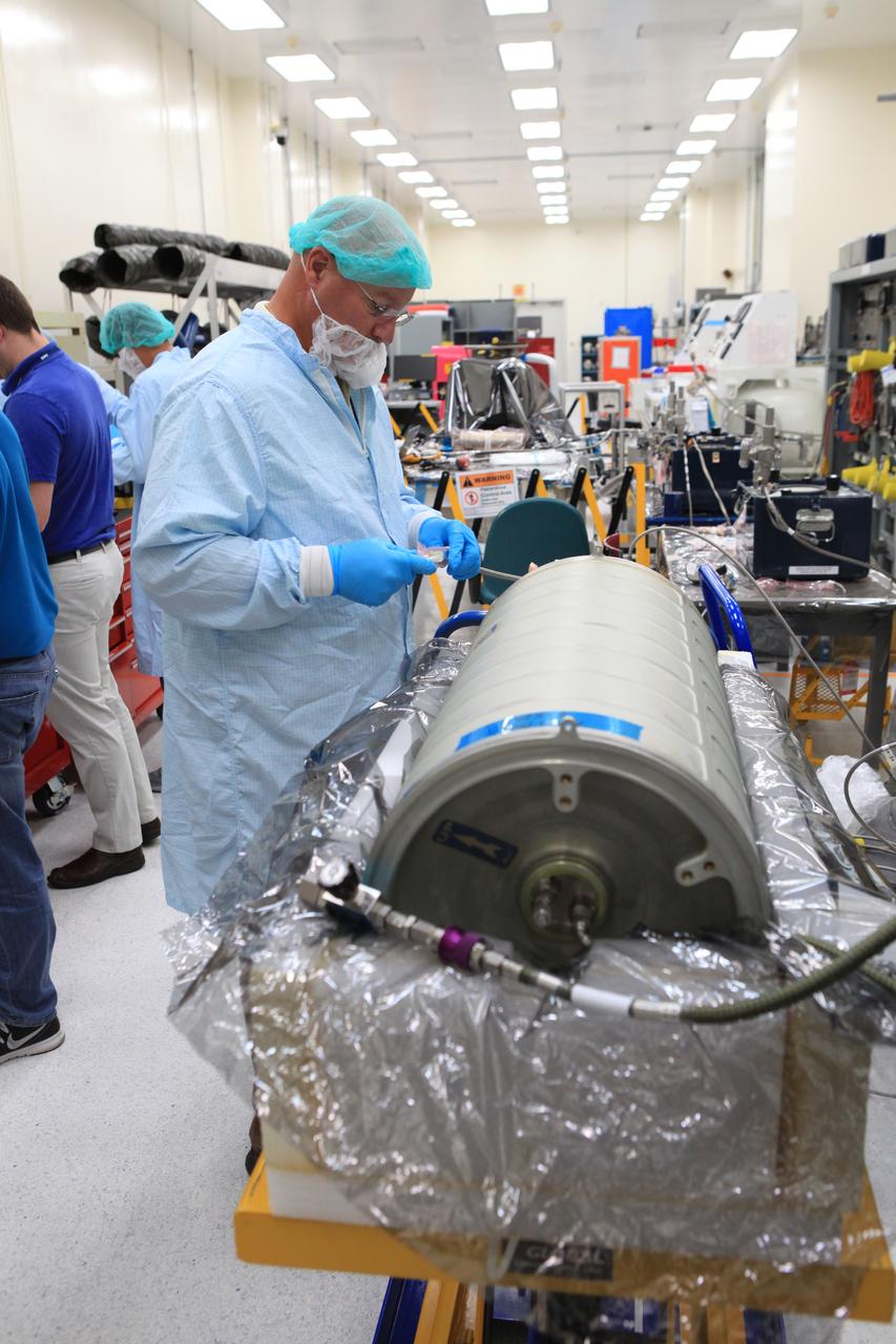
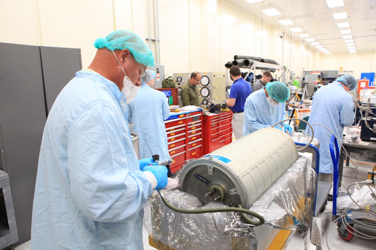
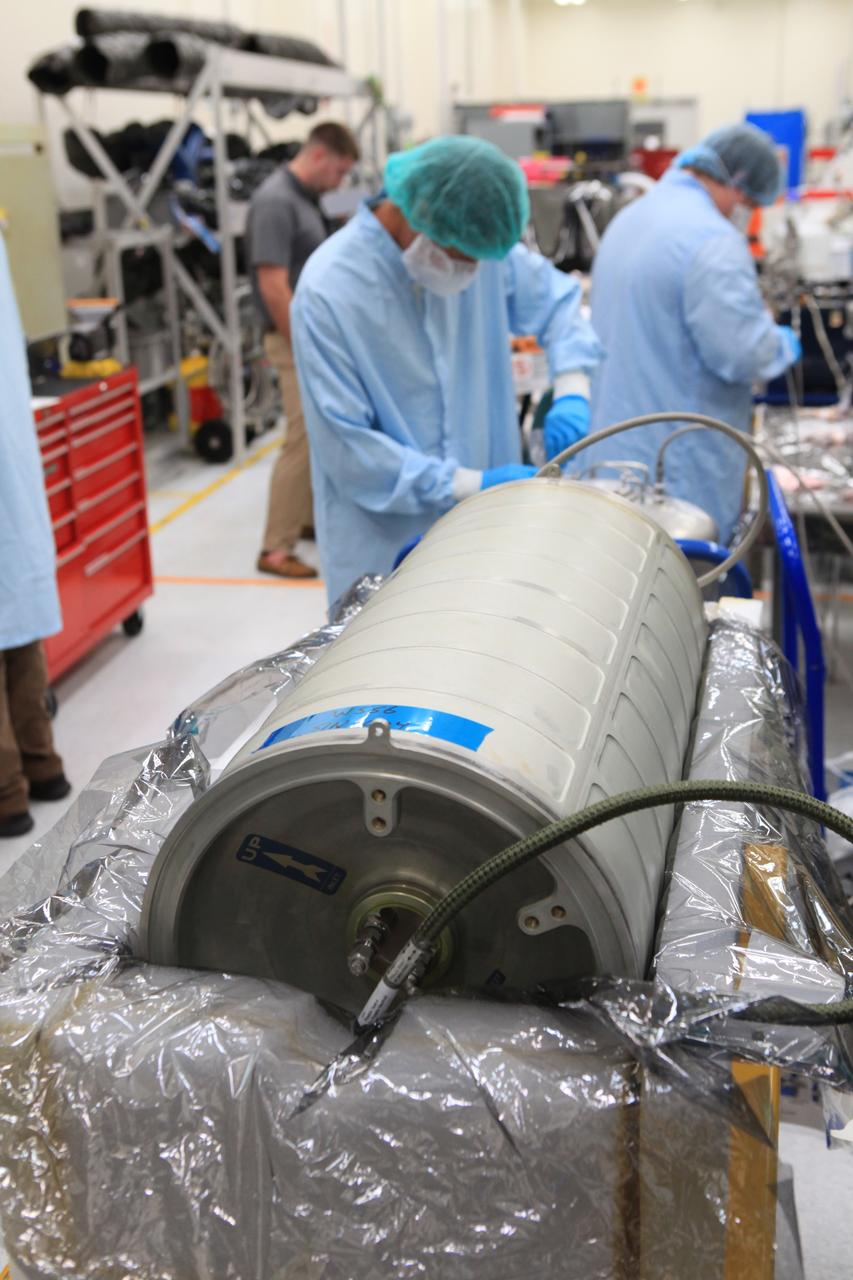
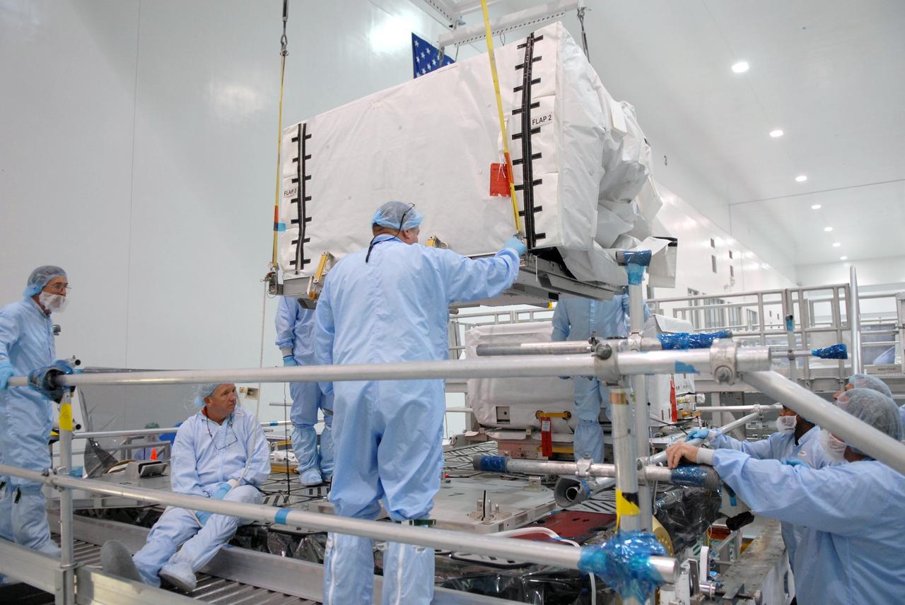
Inside the Space Station Processing Facility high bay at NASA's Kennedy Space Center in Florida, a technician works on the pump package assembly (PPA) on Aug. 30, 2018. The payload will be carried to the International Space Station on SpaceX's 16th Commercial Resupply Services mission. The PPA will be used to continuously drive the cooling water in the space station's thermal control system. The assembly includes a centrifuge pump, a fine filter and gas trap for pump protection, a coarse outlet filter, sensors, and an accumulator. The PPA also will provide a reservoir used for makeup of coolant if leakage occurred. CRS-16 is scheduled to launch to the space station later this year.
Inside the Space Station Processing Facility high bay at NASA's Kennedy Space Center in Florida, technicians work on the pump package assembly (PPA) on Aug. 30, 2018. The payload will be carried to the International Space Station on SpaceX's 16th Commercial Resupply Services mission. The PPA will be used to continuously drive the cooling water in the space station's thermal control system. The assembly includes a centrifuge pump, a fine filter and gas trap for pump protection, a coarse outlet filter, sensors, and an accumulator. The PPA also will provide a reservoir used for makeup of coolant if leakage occurred. CRS-16 is scheduled to launch to the space station later this year.
Inside the Space Station Processing Facility high bay at NASA's Kennedy Space Center in Florida, technicians work on the pump package assembly (PPA) on Aug. 30, 2018. The payload will be carried to the International Space Station on SpaceX's 16th Commercial Resupply Services mission. The PPA will be used to continuously drive the cooling water in the space station's thermal control system. The assembly includes a centrifuge pump, a fine filter and gas trap for pump protection, a coarse outlet filter, sensors, and an accumulator. The PPA also will provide a reservoir used for makeup of coolant if leakage occurred. CRS-16 is scheduled to launch to the space station later this year.
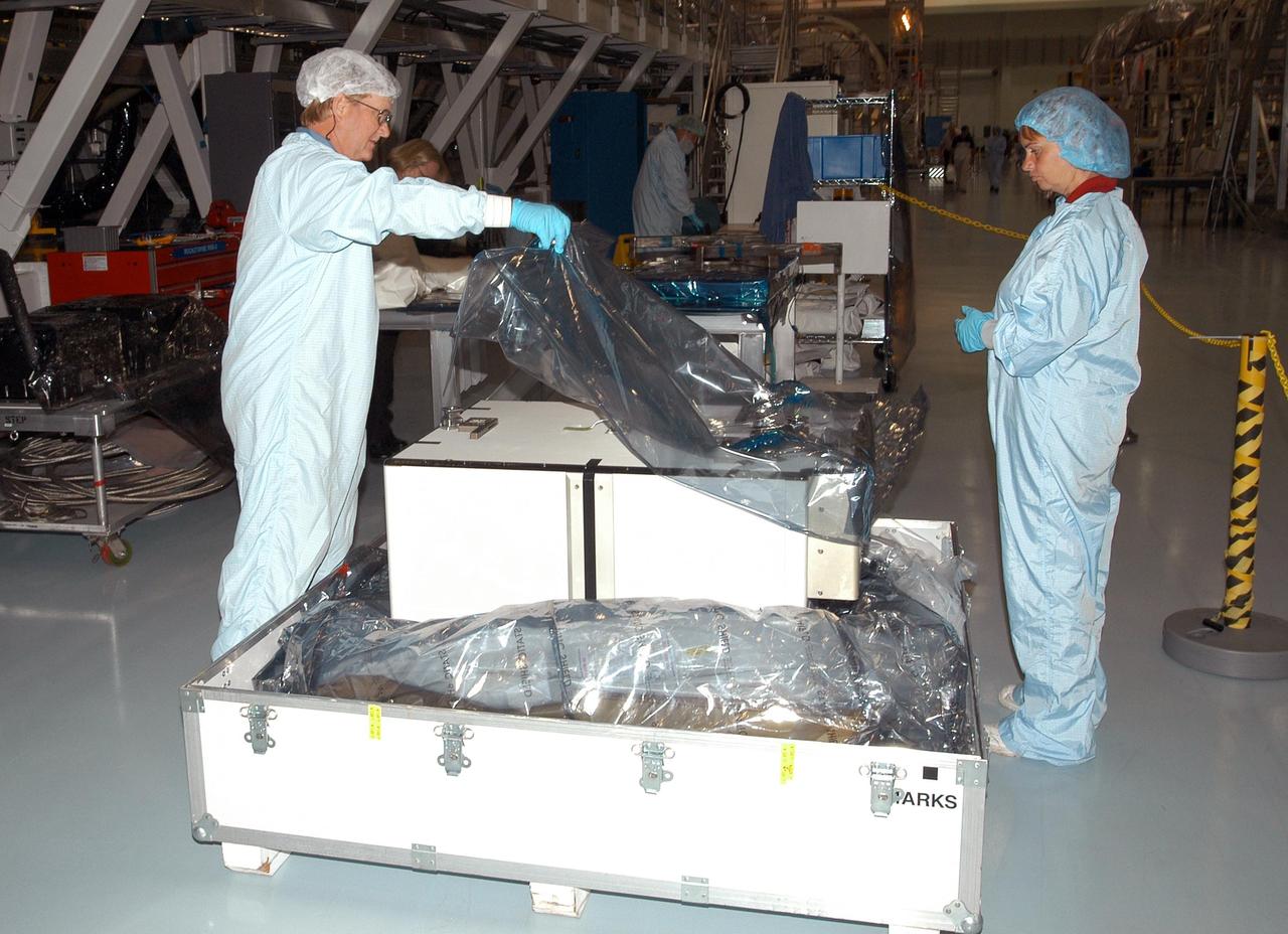
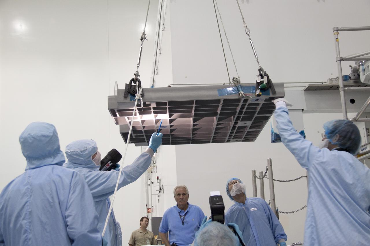
KENNEDY SPACE CENTER, FLA. - Unpacking of the Pump Flow Control Subsystem (PFCS) begins in the Space Station Processing Facility. The PFCS pumps and controls the liquid ammonia used to cool the various Orbital Replacement Units on the Integrated Equipment Assembly that make up the S6 Photo-Voltaic Power Module on the International Space Station (ISS). The fourth starboard truss segment, the S6 Truss measures 112 feet long by 39 feet wide. Its solar arrays are mounted on a “blanket” that can be folded like an accordion for delivery to the ISS. Once in orbit, astronauts will deploy the blankets to their full size. When completed, the Station's electrical power system will use eight photovoltaic solar arrays to convert sunlight to electricity. Delivery of the S6 Truss, the last power module truss segment, is targeted for mission STS-119.

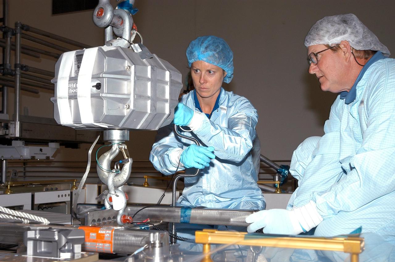
KENNEDY SPACE CENTER, FLA. - In the Space Station Processing Facility, astronaut Tracy Caldwell (left) assists a technician check out the Pump Flow Control Subsystem (PFCS) before it is installed on the upper deck of the S6 Truss. The PFCS pumps and controls the liquid ammonia used to cool the various Orbital Replacement Units on the Integrated Equipment Assembly that make up the S6 Photo-Voltaic Power Module on the International Space Station (ISS). The fourth starboard truss segment, the S6 Truss measures 112 feet long by 39 feet wide. The solar arrays are mounted on a “blanket” that can be folded like an accordion for delivery to the ISS. Once in orbit, astronauts will deploy the blankets to their full size. When completed, the Station's electrical power system (EPS) will use eight photovoltaic solar arrays to convert sunlight to electricity. Delivery of the S6 Truss, the last power module truss segment, is targeted for mission STS-119.
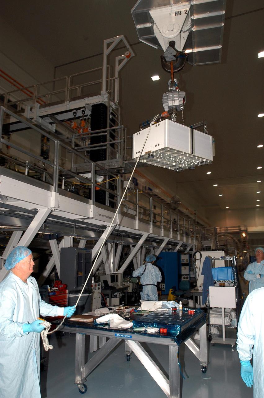
KENNEDY SPACE CENTER, FLA. - In the Space Station Processing Facility, a technician steadies the Pump Flow Control Subsystem (PFCS) as it is lifted and moved toward the S6 Truss. The PFCS pumps and controls the liquid ammonia used to cool the various Orbital Replacement Units on the Integrated Equipment Assembly that make up the S6 Photo-Voltaic Power Module on the International Space Station (ISS). The fourth starboard truss segment, the S6 Truss measures 112 feet long by 39 feet wide. Its solar arrays are mounted on a “blanket” that can be folded like an accordion for delivery to the ISS. Once in orbit, astronauts will deploy the blankets to their full size. When completed, the Station's electrical power system (EPS) will use eight photovoltaic solar arrays to convert sunlight to electricity. Delivery of the S6 Truss, the last power module truss segment, is targeted for mission STS-119.
KENNEDY SPACE CENTER, FLA. - In the Space Station Processing Facility, astronaut Tracy Caldwell (left) assists technicians install the Pump Flow Control Subsystem (PFCS) onto the upper deck of the S6 Truss. The PFCS pumps and controls the liquid ammonia used to cool the various Orbital Replacement Units on the Integrated Equipment Assembly that make up the S6 Photo-Voltaic Power Module on the International Space Station (ISS). The fourth starboard truss segment, the S6 Truss measures 112 feet long by 39 feet wide. Its solar arrays are mounted on a “blanket” that can be folded like an accordion for delivery to the ISS. Once in orbit, astronauts will deploy the blankets to their full size. When completed, the Station's electrical power system (EPS) will use eight photovoltaic solar arrays to convert sunlight to electricity. Delivery of the S6 Truss, the last power module truss segment, is targeted for mission STS-119.
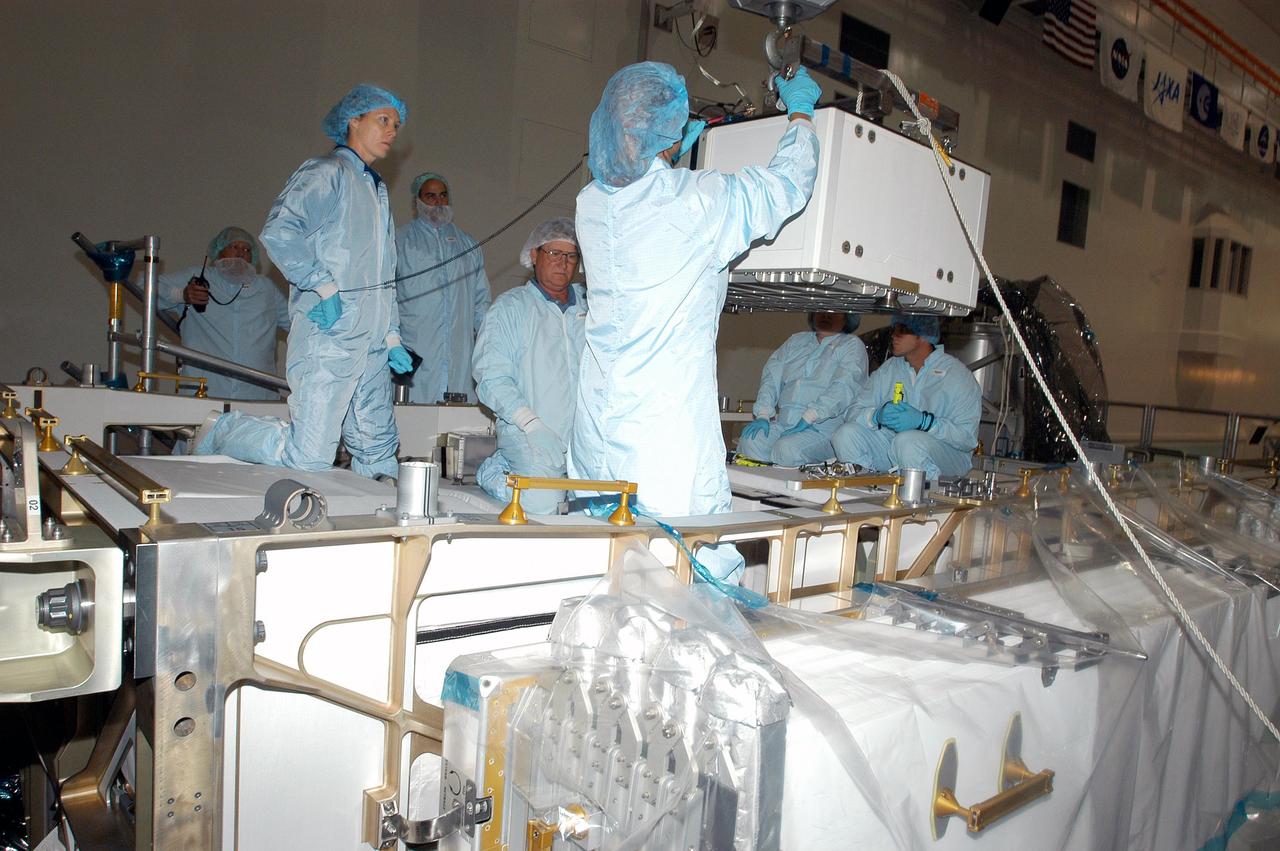
KENNEDY SPACE CENTER, FLA. - In the Space Station Processing Facility, astronaut Tracy Caldwell (second from left) assists technicians position the Pump Flow Control Subsystem (PFCS) over the upper deck of the S6 Truss. The PFCS pumps and controls the liquid ammonia used to cool the various Orbital Replacement Units on the Integrated Equipment Assembly that make up the S6 Photo-Voltaic Power Module on the International Space Station (ISS). The fourth starboard truss segment, the S6 Truss measures 112 feet long by 39 feet wide. Its solar arrays are mounted on a “blanket” that can be folded like an accordion for delivery to the ISS. Once in orbit, astronauts will deploy the blankets to their full size. When completed, the Station's electrical power system (EPS) will use eight photovoltaic solar arrays to convert sunlight to electricity. Delivery of the S6 Truss, the last power module truss segment, is targeted for mission STS-119.
KENNEDY SPACE CENTER, FLA. - Technicians attach a crane to the Pump Flow Control Subsystem (PFCS) in the Space Station Processing Facility. The PFCS pumps and controls the liquid ammonia used to cool the various Orbital Replacement Units on the Integrated Equipment Assembly that make up the S6 Photo-Voltaic Power Module on the International Space Station (ISS). The fourth starboard truss segment, the S6 Truss measures 112 feet long by 39 feet wide. Its solar arrays are mounted on a “blanket” that can be folded like an accordion for delivery to the ISS. Once in orbit, astronauts will deploy the blankets to their full size. When completed, the Station's electrical power system (EPS) will use eight photovoltaic solar arrays to convert sunlight to electricity. Delivery of the S6 Truss, the last power module truss segment, is targeted for mission STS-119.

KENNEDY SPACE CENTER, FLA. - In the Space Station Processing Facility, astronaut Tracy Caldwell (second from left) assists technicians lower the Pump Flow Control Subsystem (PFCS) into position onto the upper deck of the S6 Truss. The PFCS pumps and controls the liquid ammonia used to cool the various Orbital Replacement Units on the Integrated Equipment Assembly that make up the S6 Photo-Voltaic Power Module on the International Space Station (ISS). The fourth starboard truss segment, the S6 Truss measures 112 feet long by 39 feet wide. Its solar arrays are mounted on a “blanket” that can be folded like an accordion for delivery to the ISS. Once in orbit, astronauts will deploy the blankets to their full size. When completed, the Station's electrical power system (EPS) will use eight photovoltaic solar arrays to convert sunlight to electricity. Delivery of the S6 Truss, the last power module truss segment, is targeted for mission STS-119.
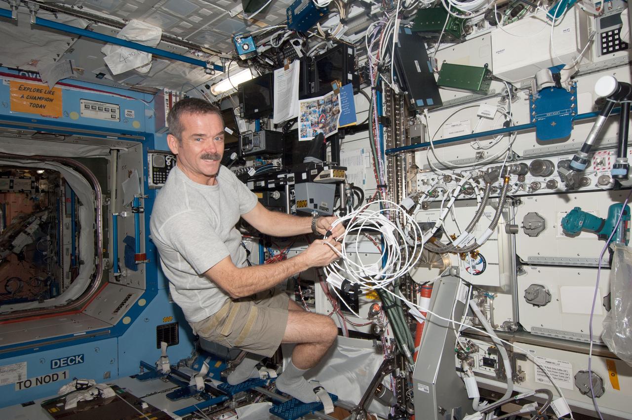
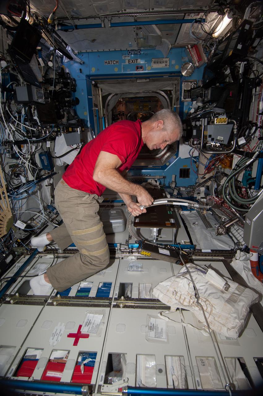
View of Canadian Space Agency (CSA) Chris Hadfield, Expedition 34 Flight Engineer (FE), wiring the condensate transfer pump, in the U.S. Laboratory. Image was released via astronaut Twitter. Original camera number is 268C1459. Photo was taken during Expedition 34.

ISS033-E-009153 (2 Oct. 2012) --- Japan Aerospace Exploration Agency astronaut Aki Hoshide, Expedition 33 flight engineer, performs a removal and replacement of the DKiV water pump and the E-K pre-treat tank with its hose in the Tranquility node of the International Space Station. E-K contains five liters of pre-treat solution, i.e., a mix of H2SO4 (sulfuric acid), CrO3 (chromium oxide, for oxidation and purple color) and H2O (water). The pre-treat liquid is mixed with water in the DKiV dispenser and used for toilet flushing.
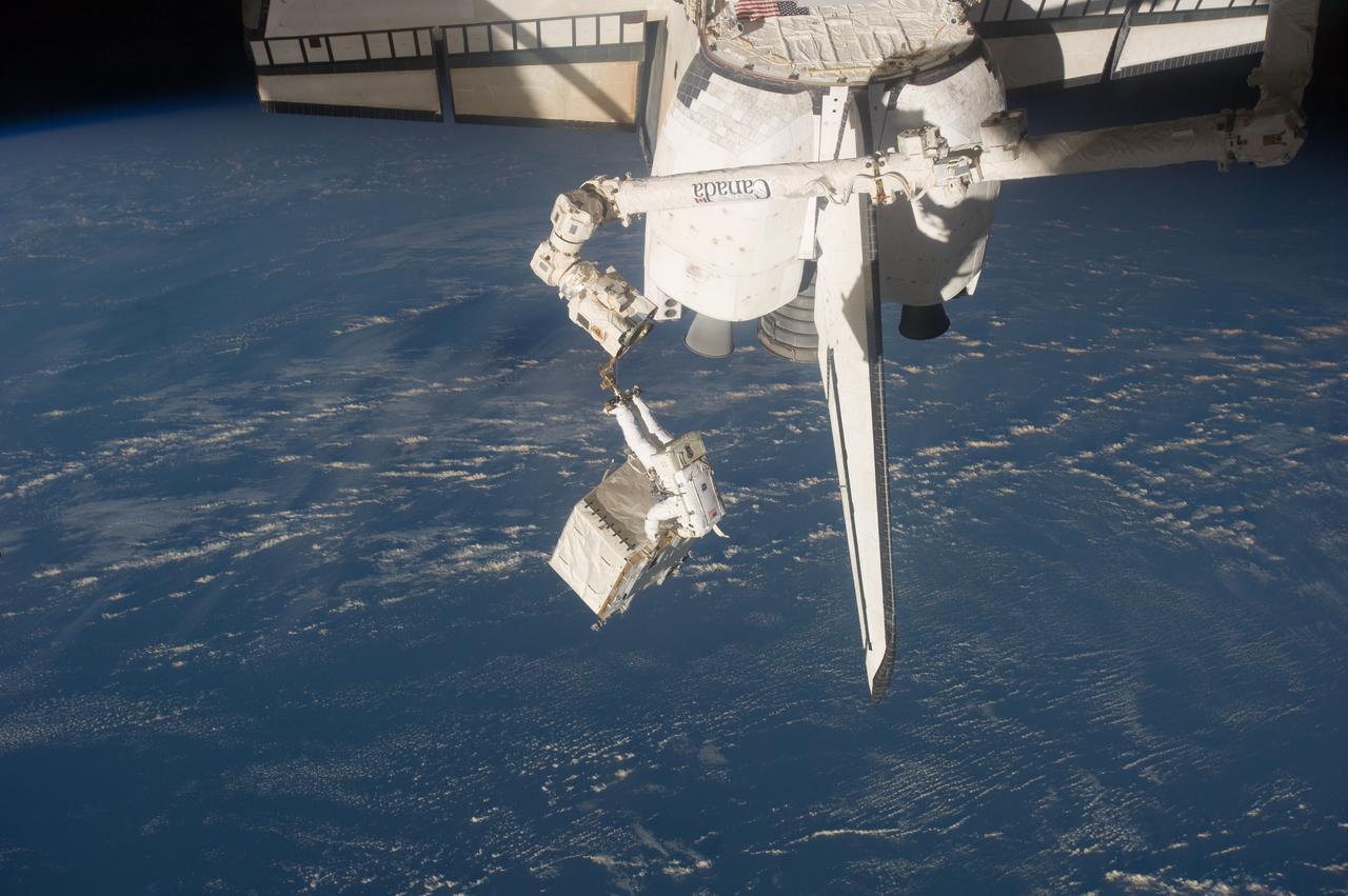
S135-E-007515 (12 July 2011) --- With his feet secured on a restraint on the space station remote manipulator system’s robotic arm or Canadarm2, NASA astronaut Ron Garan, Expedition 28 flight engineer, carries the pump module, which was the focus of one of the primary chores accomplished on a six and a half hour spacewalk on July 12. NASA astronaut Mike Fossum, also a station flight engineer, who shared the spacewalk with Garan, is out of frame. Photo credit: NASA
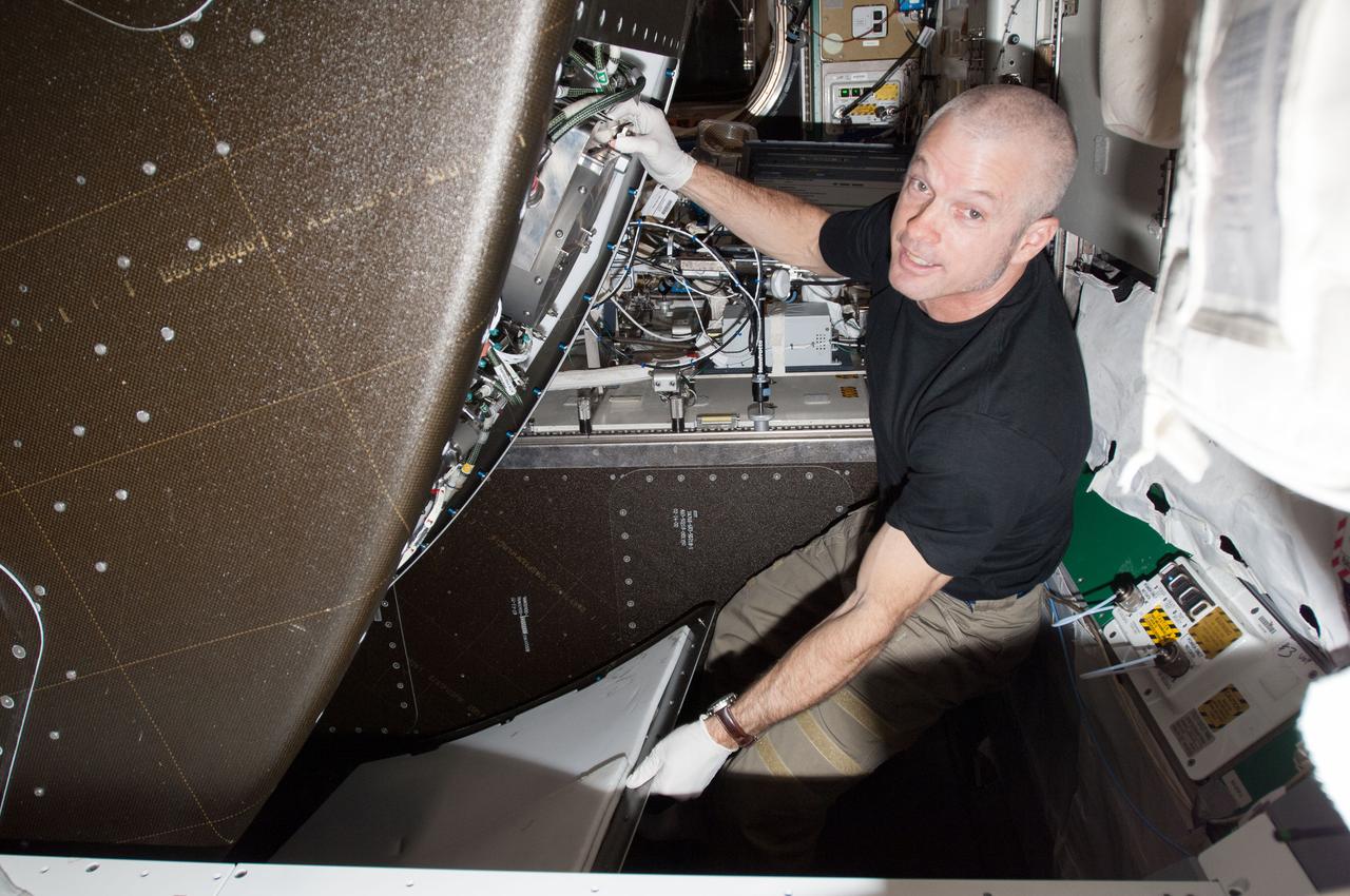
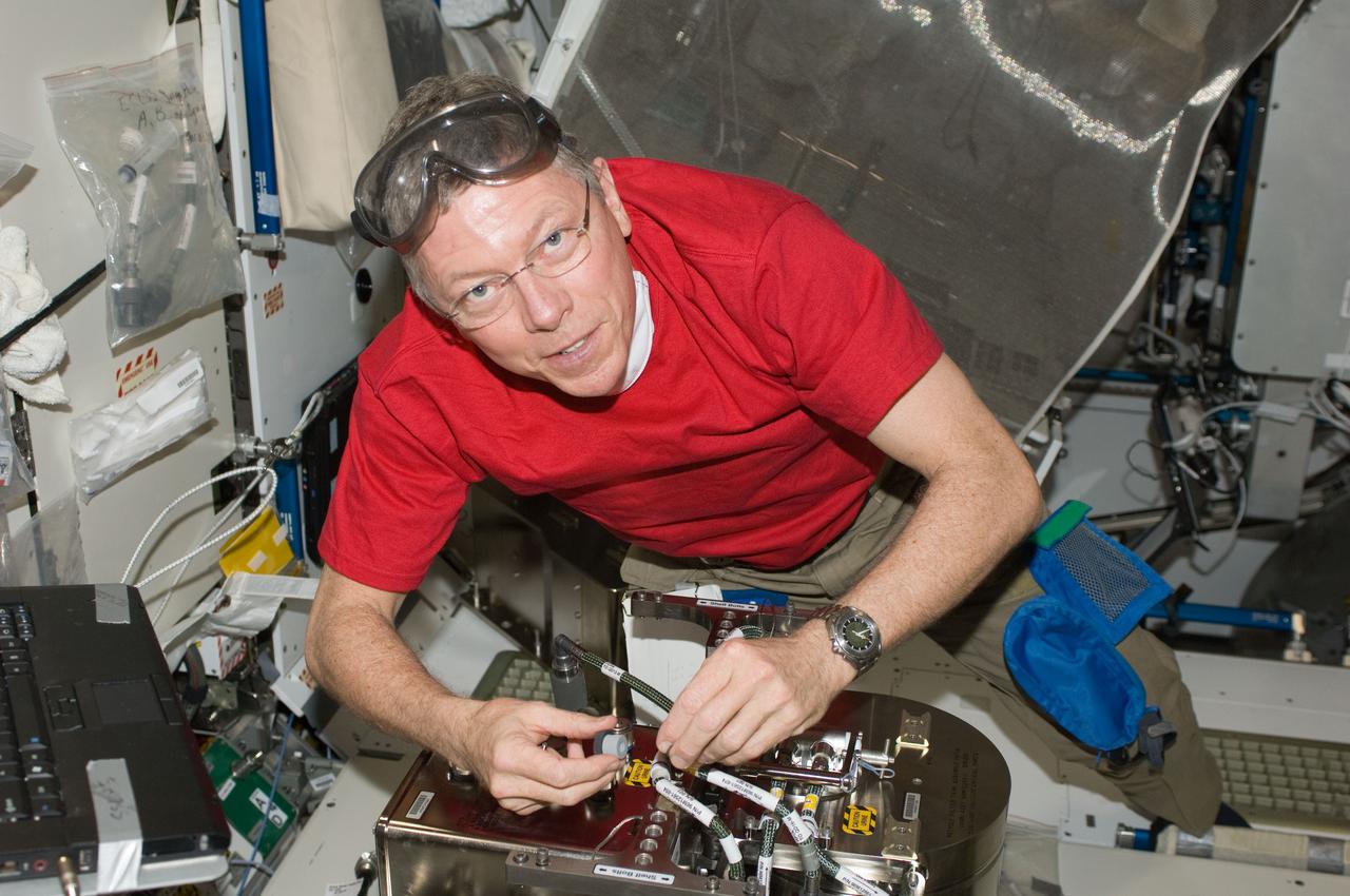
ISS040-E-026307 (1 July 2014) --- NASA astronaut Steve Swanson, Expedition 40 commander, performs in-flight maintenance behind a rack in the Tranquility node of the International Space Station.
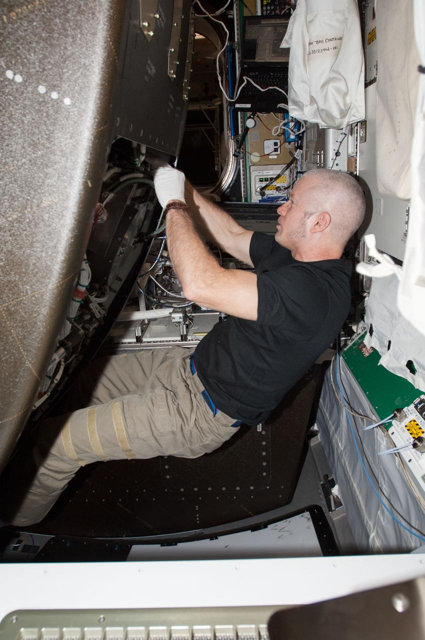
ISS040-E-026305 (1 July 2014) --- NASA astronaut Steve Swanson, Expedition 40 commander, performs in-flight maintenance behind a rack in the Tranquility node of the International Space Station.
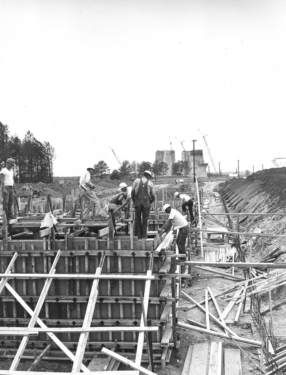
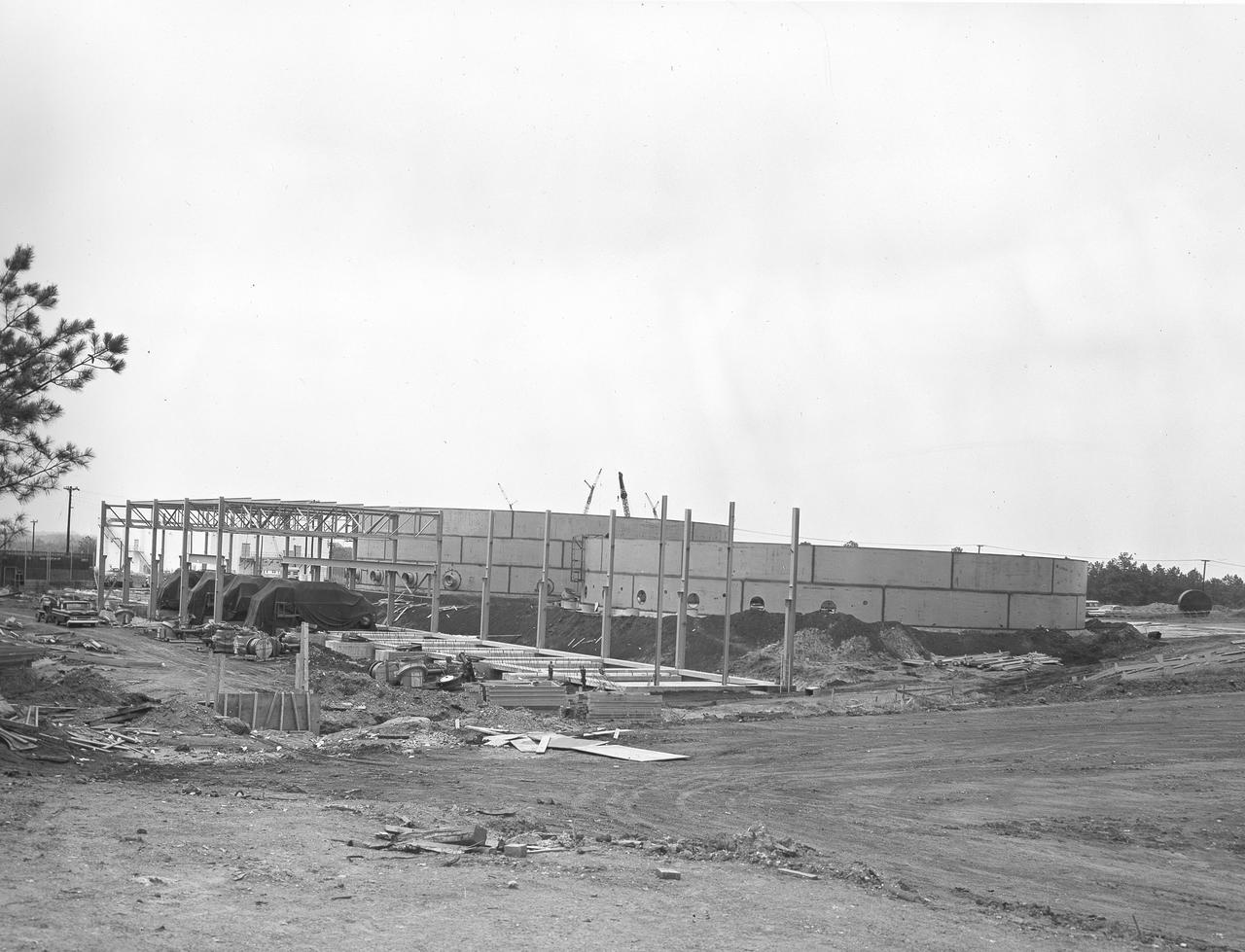
At its founding, the Marshall Space Flight Center (MSFC) inherited the Army’s Jupiter and Redstone test stands, but much larger facilities were needed for the giant stages of the Saturn V. From 1960 to 1964, the existing stands were remodeled and a sizable new test area was developed. The new comprehensive test complex for propulsion and structural dynamics was unique within the nation and the free world, and they remain so today because they were constructed with foresight to meet the future as well as on going needs. Construction of the S-IC Static test stand complex began in 1961 in the west test area of MSFC, and was completed in 1964. The S-IC static test stand was designed to develop and test the 138-ft long and 33-ft diameter Saturn V S-IC first stage, or booster stage, weighing in at 280,000 pounds. Required to hold down the brute force of a 7,500,000-pound thrust produced by 5 F-1 engines, the S-IC static test stand was designed and constructed with the strength of hundreds of tons of steel and 12,000,000 pounds of cement, planted down to bedrock 40 feet below ground level. The foundation walls, constructed with concrete and steel, are 4 feet thick. The base structure consists of four towers with 40-foot-thick walls extending upward 144 feet above ground level. The structure was topped by a crane with a 135-foot boom. With the boom in the upright position, the stand was given an overall height of 405 feet, placing it among the highest structures in Alabama at the time. In addition to the stand itself, related facilities were constructed during this time. Built directly east of the test stand was the Block House, which served as the control center for the test stand. The two were connected by a narrow access tunnel which housed the cables for the controls. Again to the east, just south of the Block House, was a newly constructed Pump House. Its function was to provide water to the stand to prevent melting damage during testing. The water was sprayed through small holes in the stand’s 1900 ton water deflector at the rate of 320,000 gallons per minute. In this photo, taken May 22, 1963, the Pump House is undergoing construction.
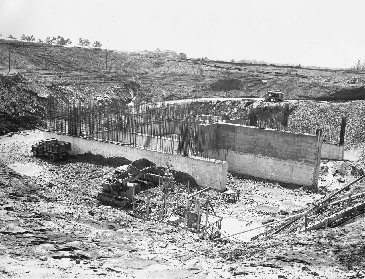
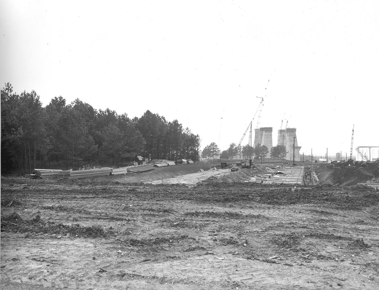
At its founding, the Marshall Space Flight Center (MSFC) inherited the Army’s Jupiter and Redstone test stands, but much larger facilities were needed for the giant stages of the Saturn V. From 1960 to 1964, the existing stands were remodeled and a sizable new test area was developed. The new comprehensive test complex for propulsion and structural dynamics was unique within the nation and the free world, and they remain so today because they were constructed with foresight to meet the future as well as on going needs. Construction of the S-IC Static test stand complex began in 1961 in the west test area of MSFC, and was completed in 1964. The S-IC static test stand was designed to develop and test the 138-ft long and 33-ft diameter Saturn V S-IC first stage, or booster stage, weighing in at 280,000 pounds. Required to hold down the brute force of a 7,500,000-pound thrust produced by 5 F-1 engines, the S-IC static test stand was designed and constructed with the strength of hundreds of tons of steel and 12,000,000 pounds of cement, planted down to bedrock 40 feet below ground level. The foundation walls, constructed with concrete and steel, are 4 feet thick. The base structure consists of four towers with 40-foot-thick walls extending upward 144 feet above ground level. The structure was topped by a crane with a 135-foot boom. With the boom in the upright position, the stand was given an overall height of 405 feet, placing it among the highest structures in Alabama at the time. In addition to the stand itself, related facilities were constructed during this time. Built directly east of the test stand was the Block House, which served as the control center for the test stand. The two were connected by a narrow tunnel which housed the cables for the controls. Again to the east, just south of the Block House, was a newly constructed Pump House. Its function was to provide water to the stand to prevent melting damage during testing. The water was sprayed through small holes in the stand’s 1900 ton water deflector at the rate of 320,000 gallons per minute. In this photo, taken March 20, 1962, construction of the Pump House area is well underway.
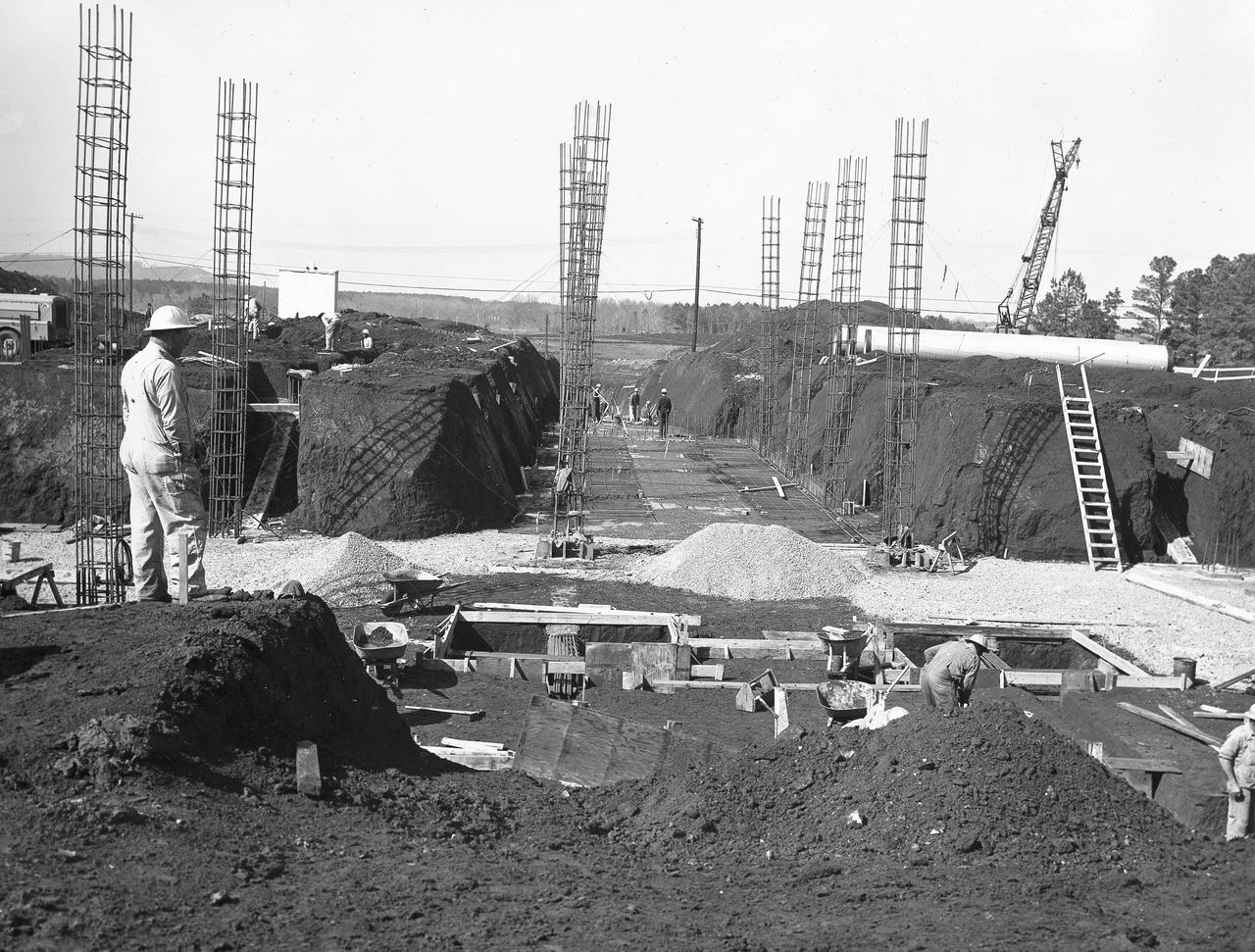
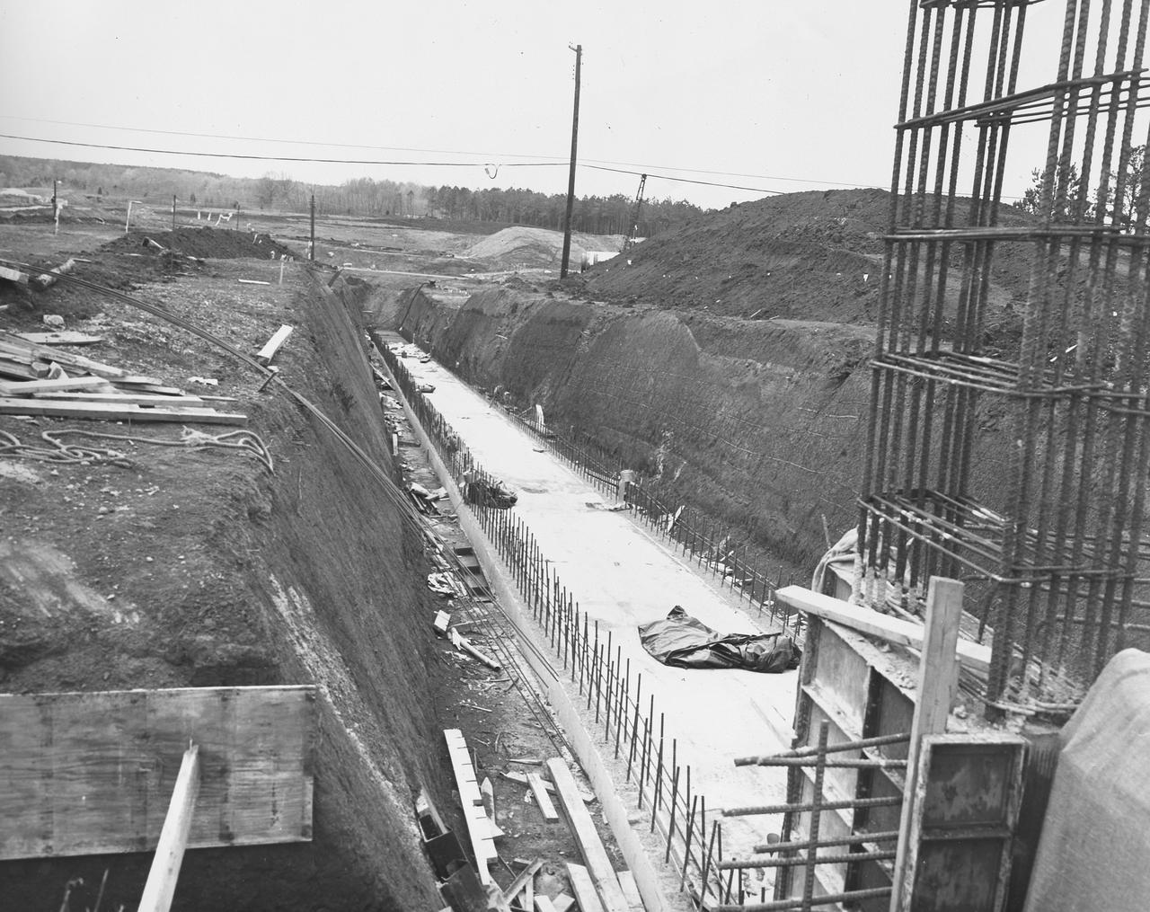
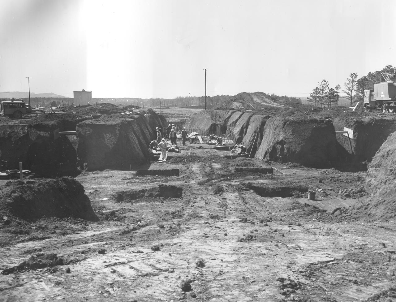
At its founding, the Marshall Space Flight Center (MSFC) inherited the Army’s Jupiter and Redstone test stands, but much larger facilities were needed for the giant stages of the Saturn V. From 1960 to 1964, the existing stands were remodeled and a sizable new test area was developed. The new comprehensive test complex for propulsion and structural dynamics was unique within the nation and the free world, and they remain so today because they were constructed with foresight to meet the future as well as on going needs. Construction of the S-IC Static test stand complex began in 1961 in the west test area of MSFC, and was completed in 1964. The S-IC static test stand was designed to develop and test the 138-ft long and 33-ft diameter Saturn V S-IC first stage, or booster stage, weighing in at 280,000 pounds. Required to hold down the brute force of a 7,500,000-pound thrust produced by 5 F-1 engines, the S-IC static test stand was designed and constructed with the strength of hundreds of tons of steel and 12,000,000 pounds of cement, planted down to bedrock 40 feet below ground level. The foundation walls, constructed with concrete and steel, are 4 feet thick. The base structure consists of four towers with 40-foot-thick walls extending upward 144 feet above ground level. The structure was topped by a crane with a 135-foot boom. With the boom in the upright position, the stand was given an overall height of 405 feet, placing it among the highest structures in Alabama at the time. This photo, taken April 4, 1961, shows the S-IC test stand dry once again when workers resumed construction after a 6 month delay due to booster size reconfiguration back in September of 1961. The disturbance of a natural spring during the excavation of the site required water to be pumped from the site continuously. The site was completely flooded after the pumps were shut down during the construction delay.
At its founding, the Marshall Space Flight Center (MSFC) inherited the Army’s Jupiter and Redstone test stands, but much larger facilities were needed for the giant stages of the Saturn V. From 1960 to 1964, the existing stands were remodeled and a sizable new test area was developed. The new comprehensive test complex for propulsion and structural dynamics was unique within the nation and the free world, and they remain so today because they were constructed with foresight to meet the future as well as on going needs. Construction of the S-IC Static test stand complex began in 1961 in the west test area of MSFC, and was completed in 1964. The S-IC static test stand was designed to develop and test the 138-ft long and 33-ft diameter Saturn V S-IC first stage, or booster stage, weighing in at 280,000 pounds. Required to hold down the brute force of a 7,500,000-pound thrust produced by 5 F-1 engines, the S-IC static test stand was designed and constructed with the strength of hundreds of tons of steel and 12,000,000 pounds of cement, planted down to bedrock 40 feet below ground level. The foundation walls, constructed with concrete and steel, are 4 feet thick. The base structure consists of four towers with 40-foot-thick walls extending upward 144 feet above ground level. The structure was topped by a crane with a 135-foot boom. With the boom in the upright position, the stand was given an overall height of 405 feet, placing it among the highest structures in Alabama at the time. In addition to the stand itself, related facilities were constructed during this time. Built directly east of the test stand was the Block House, which served as the control center for the test stand. The two were connected by a narrow access tunnel which housed the cables for the controls. Again to the east, just south of the Block House, was a newly constructed Pump House. Its function was to provide water to the stand to prevent melting damage during testing. The water was sprayed through small holes in the stand’s 1900 ton water deflector at the rate of 320,000 gallons per minute. In this photo, taken May 22, 1963, the Pump House is undergoing construction.
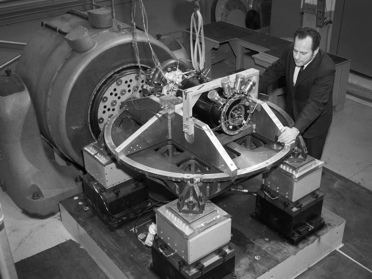
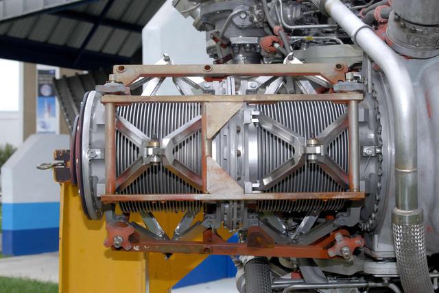
Aeronautics and Space Administration (NASA) Lewis Research Center. Aerojet General was contracted to design the SNAP-8 generator which employed a mercury Rankine system to convert the reactor’s heat into electrical power. The hermetically-sealed pump was designed to generate from 35 to 90 kilowatts of electrical power. In 1964 a SNAP-8 test rig with a mercury boiler and condenser was set up in cell W-1 of Lewis’ Engine Research Building to study the transients in the system’s three loops. In 1967 a complete Rankine system was operated for 60 days in W-1 to verify the integrity of the Lewis-developed mercury boiler. Further tests in 1969 verified the shutdown and startup of the system under normal and emergency conditions. Aerojet operated the first full-Rankine system in June 1966 and completed a 2500-hour endurance test in early 1969. Lewis and Aerojet’s success on the Rankine system was acknowledged with NASA Group Achievement Award in November 1970. The 1970 vibration tests, seen here, were conducted in Lewis’ Engine Research Building’s environmental laboratory. The testing replicated the shock and vibration expected to occur during the launch into space and subsequent maneuvering. The pump was analyzed on each of its major axes.
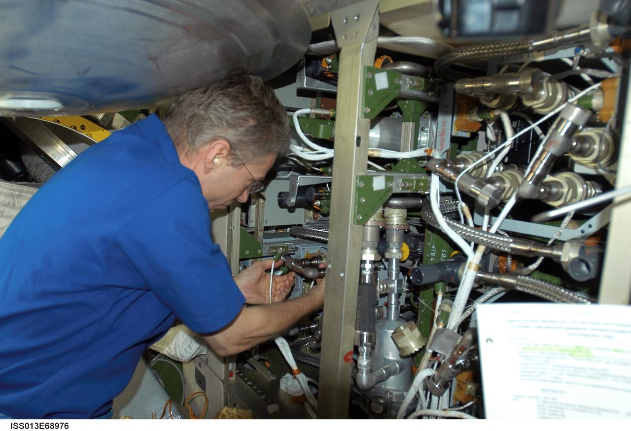
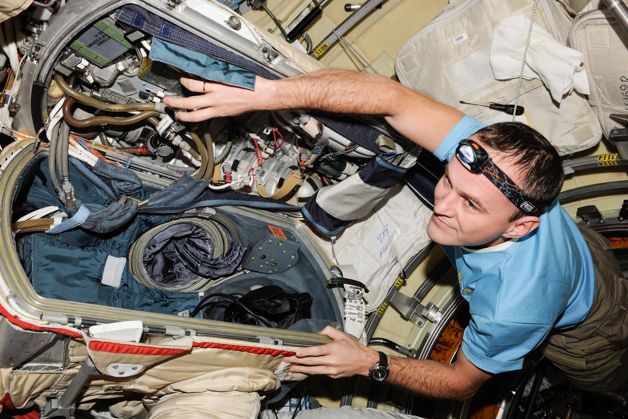
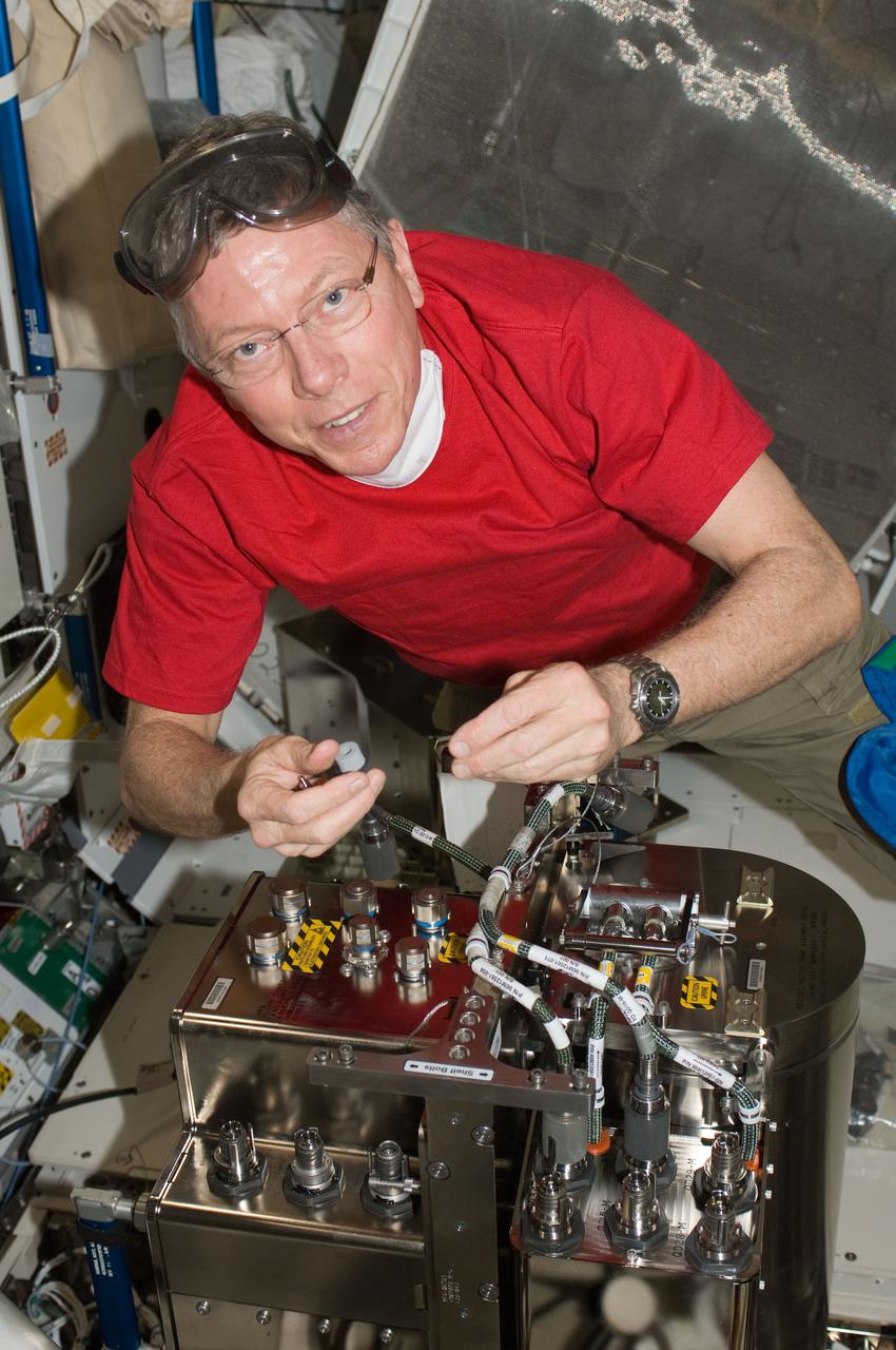
ISS013-E-68976 (August 2006) --- European Space Agency (ESA) astronaut Thomas Reiter, Expedition 13 flight engineer, works on the internal thermal cooling loop pump in the Zvezda Service Module of the International Space Station.
At its founding, the Marshall Space Flight Center (MSFC) inherited the Army’s Jupiter and Redstone test stands, but much larger facilities were needed for the giant stages of the Saturn V. From 1960 to 1964, the existing stands were remodeled and a sizable new test area was developed. The new comprehensive test complex for propulsion and structural dynamics was unique within the nation and the free world, and they remain so today because they were constructed with foresight to meet the future as well as on going needs. Construction of the S-IC Static test stand complex began in 1961 in the west test area of MSFC, and was completed in 1964. The S-IC static test stand was designed to develop and test the 138-ft long and 33-ft diameter Saturn V S-IC first stage, or booster stage, weighing in at 280,000 pounds. Required to hold down the brute force of a 7,500,000-pound thrust produced by 5 F-1 engines, the S-IC static test stand was designed and constructed with the strength of hundreds of tons of steel and 12,000,000 pounds of cement, planted down to bedrock 40 feet below ground level. The foundation walls, constructed with concrete and steel, are 4 feet thick. The base structure consists of four towers with 40-foot-thick walls extending upward 144 feet above ground level. The structure was topped by a crane with a 135-foot boom. With the boom in the upright position, the stand was given an overall height of 405 feet, placing it among the highest structures in Alabama at the time. In addition to the stand itself, related facilities were constructed during this time. Built directly east of the test stand was the Block House, which served as the control center for the test stand. The two were connected by a narrow tunnel which housed the cables for the controls. Again to the east, just south of the Block House, was a newly constructed Pump House. Its function was to provide water to the stand to prevent melting damage during testing. The water was sprayed through small holes in the stand’s 1900 ton water deflector at the rate of 320,000 gallons per minute. This photograph, taken Aril 16, 1962, depicts the water line area through which the pump house delivered water to the stand.
At its founding, the Marshall Space Flight Center (MSFC) inherited the Army’s Jupiter and Redstone test stands, but much larger facilities were needed for the giant stages of the Saturn V. From 1960 to 1964, the existing stands were remodeled and a sizable new test area was developed. The new comprehensive test complex for propulsion and structural dynamics was unique within the nation and the free world, and they remain so today because they were constructed with foresight to meet the future as well as on going needs. Construction of the S-IC Static test stand complex began in 1961 in the west test area of MSFC, and was completed in 1964. The S-IC static test stand was designed to develop and test the 138-ft long and 33-ft diameter Saturn V S-IC first stage, or booster stage, weighing in at 280,000 pounds. Required to hold down the brute force of a 7,500,000-pound thrust produced by 5 F-1 engines, the S-IC static test stand was designed and constructed with the strength of hundreds of tons of steel and 12,000,000 pounds of cement, planted down to bedrock 40 feet below ground level. The foundation walls, constructed with concrete and steel, are 4 feet thick. The base structure consists of four towers with 40-foot-thick walls extending upward 144 feet above ground level. The structure was topped by a crane with a 135-foot boom. With the boom in the upright position, the stand was given an overall height of 405 feet, placing it among the highest structures in Alabama at the time. In addition to the stand itself, related facilities were constructed during this time. Built directly east of the test stand was the Block House, which served as the control center for the test stand. The two were connected by a narrow tunnel which housed the cables for the controls. Again to the east, just south of the Block House, was a newly constructed Pump House. Its function was to provide water to the stand to prevent melting damage during testing. The water was sprayed through small holes in the stand’s 1900 ton water deflector at the rate of 320,000 gallons per minute. In this photo taken March 20, 1962, construction is well underway in the water line area connecting the Pump House to the S-IC test stand.
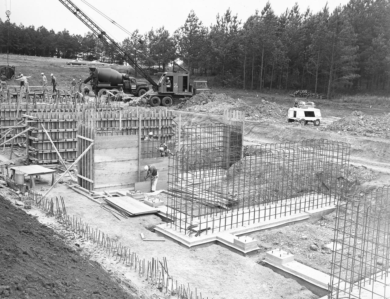
At its founding, the Marshall Space Flight Center (MSFC) inherited the Army’s Jupiter and Redstone test stands, but much larger facilities were needed for the giant stages of the Saturn V. From 1960 to 1964, the existing stands were remodeled and a sizable new test area was developed. The new comprehensive test complex for propulsion and structural dynamics was unique within the nation and the free world, and they remain so today because they were constructed with foresight to meet the future as well as on going needs. Construction of the S-IC Static test stand complex began in 1961 in the west test area of MSFC, and was completed in 1964. The S-IC static test stand was designed to develop and test the 138-ft long and 33-ft diameter Saturn V S-IC first stage, or booster stage, weighing in at 280,000 pounds. Required to hold down the brute force of a 7,500,000-pound thrust produced by 5 F-1 engines, the S-IC static test stand was designed and constructed with the strength of hundreds of tons of steel and 12,000,000 pounds of cement, planted down to bedrock 40 feet below ground level. The foundation walls, constructed with concrete and steel, are 4 feet thick. The base structure consists of four towers with 40-foot-thick walls extending upward 144 feet above ground level. The structure was topped by a crane with a 135-foot boom. With the boom in the upright position, the stand was given an overall height of 405 feet, placing it among the highest structures in Alabama at the time. In addition to the stand itself, related facilities were constructed during this time. Built directly east of the test stand was the Block House, which served as the control center for the test stand. The two were connected by a narrow access tunnel which housed the cables for the controls. Again to the east, just south of the Block House, was a newly constructed Pump House. Its function was to provide water to the stand to prevent melting damage during testing. The water was sprayed through small holes in the stand’s 1900 ton water deflector at the rate of 320,000 gallons per minute. In this photo, taken July 3, 1963, the Pump House is undergoing construction and has reached ground level.
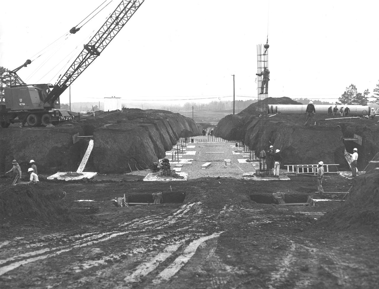
At its founding, the Marshall Space Flight Center (MSFC) inherited the Army’s Jupiter and Redstone test stands, but much larger facilities were needed for the giant stages of the Saturn V. From 1960 to 1964, the existing stands were remodeled and a sizable new test area was developed. The new comprehensive test complex for propulsion and structural dynamics was unique within the nation and the free world, and they remain so today because they were constructed with foresight to meet the future as well as on going needs. Construction of the S-IC Static test stand complex began in 1961 in the west test area of MSFC, and was completed in 1964. The S-IC static test stand was designed to develop and test the 138-ft long and 33-ft diameter Saturn V S-IC first stage, or booster stage, weighing in at 280,000 pounds. Required to hold down the brute force of a 7,500,000-pound thrust produced by 5 F-1 engines, the S-IC static test stand was designed and constructed with the strength of hundreds of tons of steel and 12,000,000 pounds of cement, planted down to bedrock 40 feet below ground level. The foundation walls, constructed with concrete and steel, are 4 feet thick. The base structure consists of four towers with 40-foot-thick walls extending upward 144 feet above ground level. The structure was topped by a crane with a 135-foot boom. With the boom in the upright position, the stand was given an overall height of 405 feet, placing it among the highest structures in Alabama at the time. In addition to the stand itself, related facilities were constructed during this time. Built directly east of the test stand was the Block House, which served as the control center for the test stand. The two were connected by a narrow access tunnel which housed the cables for the controls. Again to the east, just south of the Block House, was a newly constructed Pump House. Its function was to provide water to the stand to prevent melting damage during testing. The water was sprayed through small holes in the S-IC test stand’s 1900 ton water deflector at the rate of 320,000 gallons per minute. This photo, taken March 15, 1962, shows the excavation of the water line area connecting the Pump House to the S-IC test stand.
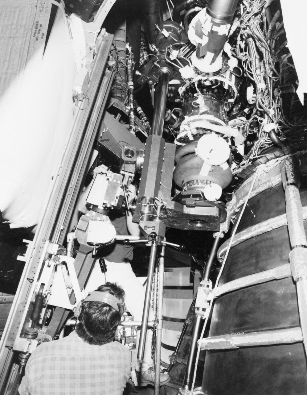
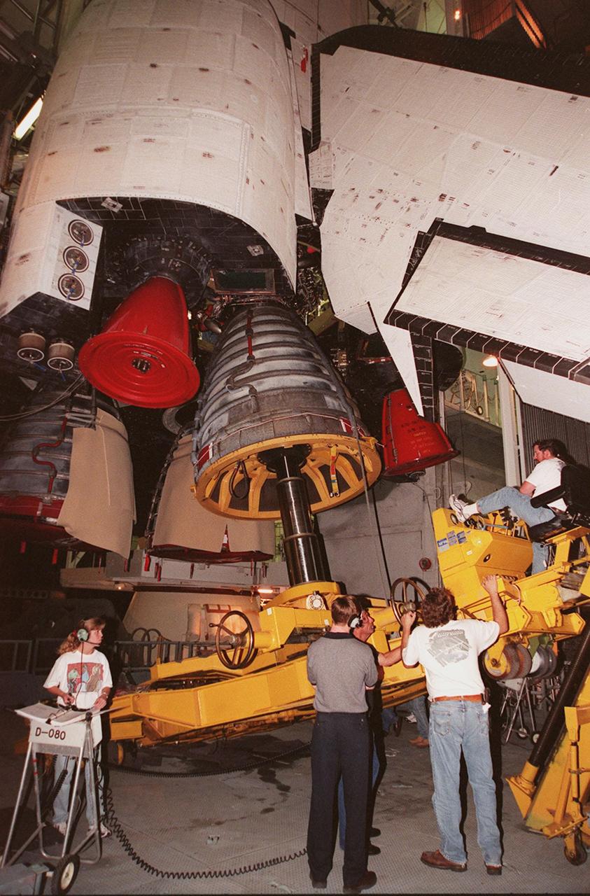
S89-28092 (7 Feb 1989) --- Kennedy Space Center technicians inspect an area near the three main engines of the Space Shuttle Discovery prior to the removal of one of three oxidozer turbo pumps. New pumps are scheduled to be installed soon. Now at Launch Pad 39-B, Discovery is set for launch in mid-March for Mission STS-29. Primary payload will be TDRS-D. Crewmembers are Astronauts Michael L. Coats, mission commander, John E. Blaha, pilot; along with James F. Buchli, Robert C. Springer and James P. Bagian, all mission specialists.
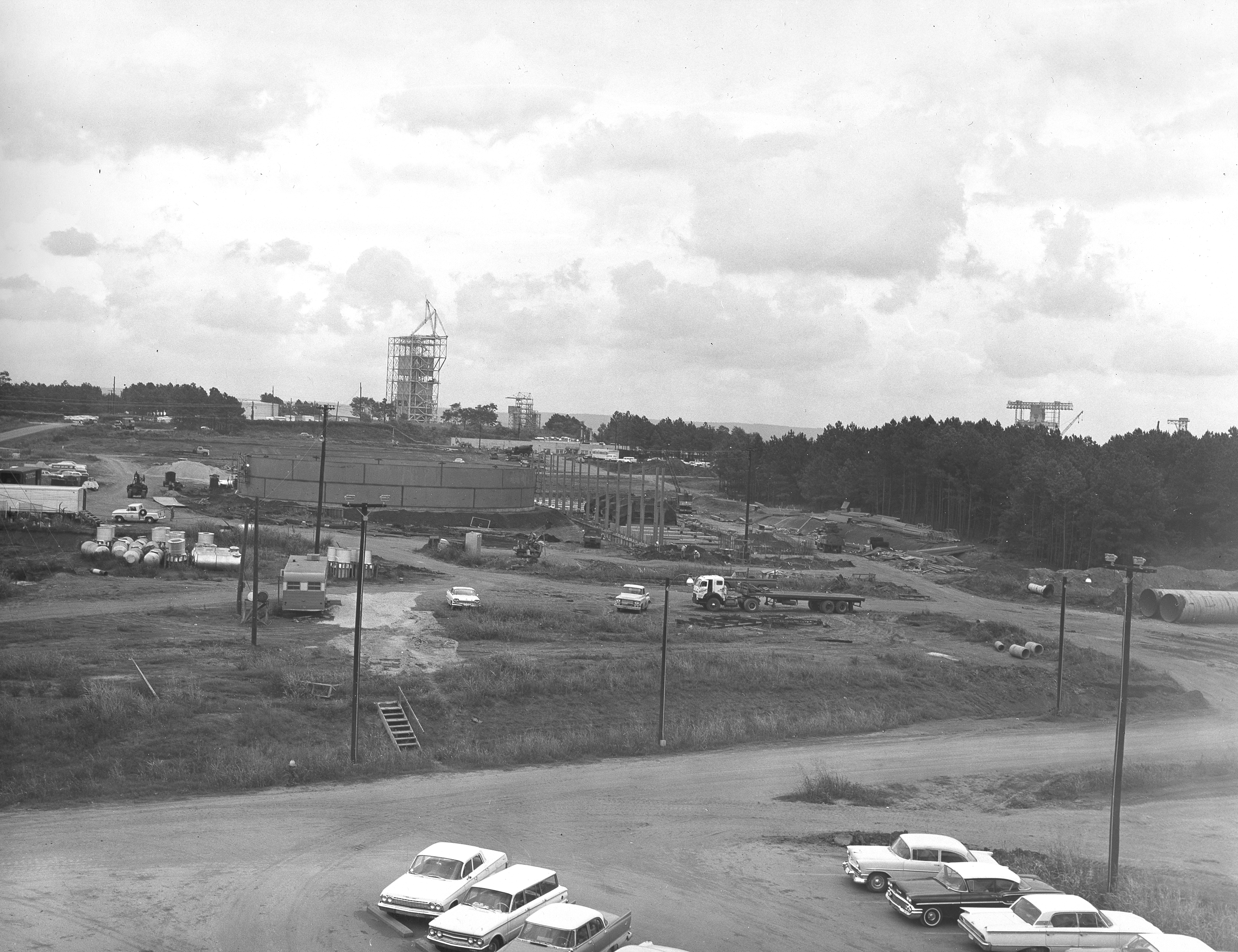
At its founding, the Marshall Space Flight Center (MSFC) inherited the Army’s Jupiter and Redstone test stands, but much larger facilities were needed for the giant stages of the Saturn V. From 1960 to 1964, the existing stands were remodeled and a sizable new test area was developed. The new comprehensive test complex for propulsion and structural dynamics was unique within the nation and the free world, and they remain so today because they were constructed with foresight to meet the future as well as on going needs. Construction of the S-IC Static test stand complex began in 1961 in the west test area of MSFC, and was completed in 1964. The S-IC static test stand was designed to develop and test the 138-ft long and 33-ft diameter Saturn V S-IC first stage, or booster stage, weighing in at 280,000 pounds. Required to hold down the brute force of a 7,500,000-pound thrust produced by 5 F-1 engines, the S-IC static test stand was designed and constructed with the strength of hundreds of tons of steel and 12,000,000 pounds of cement, planted down to bedrock 40 feet below ground level. The foundation walls, constructed with concrete and steel, are 4 feet thick. The base structure consists of four towers with 40-foot-thick walls extending upward 144 feet above ground level. The structure was topped by a crane with a 135-foot boom. With the boom in the upright position, the stand was given an overall height of 405 feet, placing it among the highest structures in Alabama at the time. In addition to the stand itself, related facilities were constructed during this time. Built to the northeast east was a newly constructed Pump House. Its function was to provide water to the stand to prevent melting damage during testing. The water was sprayed through small holes in the stand’s 1900 ton flame deflector at the rate of 320,000 gallons per minute. This photograph of the Pump House area was taken August 13, 1963. The massive round water storage tanks can be seen to the left of the Pump House.
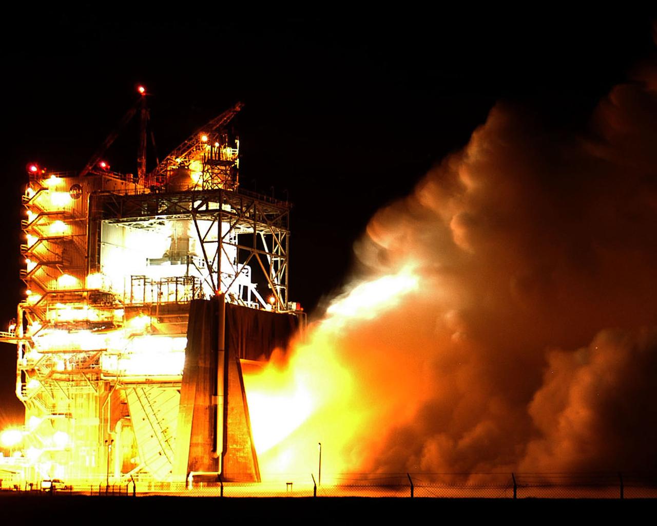
Water vapor surges from the flame deflector of the A-2 Test Stand at NASA's Stennis Space Center on Jan. 9 during the first space shuttle main engine test of the year. The test was an engine acceptance test of flight engine 2058. It's the first space shuttle main engine to be completely assembled at Kennedy Space Center. Objectives also included first-time (green run) tests of a high-pressure oxidizer turbo pump and an Advanced Health System Monitor engine controller. The test ran for the planned duration of 520 seconds.
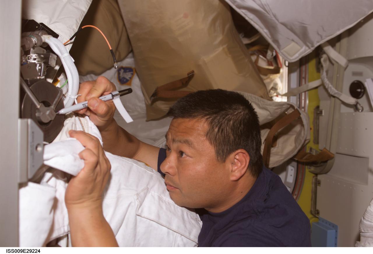
ISS009-E-29224 (19 October 2004) --- Astronaut Leroy Chiao, Expedition 10 commander and NASA ISS science officer, performs maintenance on the water pump of an Extravehicular Mobility Unit (EMU) spacesuit in the Quest Airlock of the International Space Station (ISS).
At its founding, the Marshall Space Flight Center (MSFC) inherited the Army’s Jupiter and Redstone test stands, but much larger facilities were needed for the giant stages of the Saturn V. From 1960 to 1964, the existing stands were remodeled and a sizable new test area was developed. The new comprehensive test complex for propulsion and structural dynamics was unique within the nation and the free world, and they remain so today because they were constructed with foresight to meet the future as well as on going needs. Construction of the S-IC Static test stand complex began in 1961 in the west test area of MSFC, and was completed in 1964. The S-IC static test stand was designed to develop and test the 138-ft long and 33-ft diameter Saturn V S-IC first stage, or booster stage, weighing in at 280,000 pounds. Required to hold down the brute force of a 7,500,000-pound thrust produced by 5 F-1 engines, the S-IC static test stand was designed and constructed with the strength of hundreds of tons of steel and 12,000,000 pounds of cement, planted down to bedrock 40 feet below ground level. The foundation walls, constructed with concrete and steel, are 4 feet thick. The base structure consists of four towers with 40-foot-thick walls extending upward 144 feet above ground level. The structure was topped by a crane with a 135-foot boom. With the boom in the upright position, the stand was given an overall height of 405 feet, placing it among the highest structures in Alabama at the time. In addition to the stand itself, related facilities were constructed during this time. Built to the northeast of the stand was a newly constructed Pump House. Its function was to provide water to the stand to prevent melting damage during testing. The water was sprayed through small holes in the stand’s 1900 ton flame deflector at the rate of 320,000 gallons per minute. This close up photograph, taken September 5, 1963, shows the ground level frame work for the Pump House and its massive round water storage tanks.
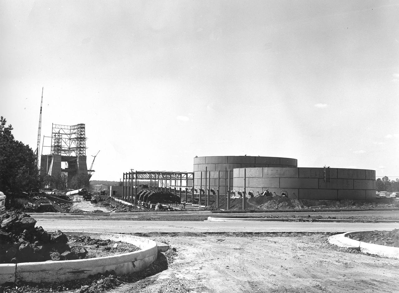
At its founding, the Marshall Space Flight Center (MSFC) inherited the Army’s Jupiter and Redstone test stands, but much larger facilities were needed for the giant stages of the Saturn V. From 1960 to 1964, the existing stands were remodeled and a sizable new test area was developed. The new comprehensive test complex for propulsion and structural dynamics was unique within the nation and the free world, and they remain so today because they were constructed with foresight to meet the future as well as on going needs. Construction of the S-IC Static test stand complex began in 1961 in the west test area of MSFC, and was completed in 1964. The S-IC static test stand was designed to develop and test the 138-ft long and 33-ft diameter Saturn V S-IC first stage, or booster stage, weighing in at 280,000 pounds. Required to hold down the brute force of a 7,500,000-pound thrust produced by 5 F-1 engines, the S-IC static test stand was designed and constructed with the strength of hundreds of tons of steel and 12,000,000 pounds of cement, planted down to bedrock 40 feet below ground level. The foundation walls, constructed with concrete and steel, are 4 feet thick. The base structure consists of four towers with 40-foot-thick walls extending upward 144 feet above ground level. The structure was topped by a crane with a 135-foot boom. With the boom in the upright position, the stand was given an overall height of 405 feet, placing it among the highest structures in Alabama at the time. In addition to the stand itself, related facilities were constructed during this time. Built to the northeast of the stand was a newly constructed Pump House. Its function was to provide water to the stand to prevent melting damage during testing. The water was sprayed through small holes in the stand’s 1900 ton flame deflector at the rate of 320,000 gallons per minute. This photograph, taken September 25, 1963, depicts the construction progress of the Pump House and massive round water tanks on the right.
Stennis Space Center engineers are preparing to conduct water tests on an updated version of the scissors duct component of the J-2X engine. Measuring about 2 feet long and about 8 inches in diameter, the duct on the J-2X predecessor, the J-2, connected its fuel turbo pumps to the flight vehicle's upper stage run tanks. According to NASA's J-2X project manager at SSC, Gary Benton, the water tests should establish the limits of the duct's ability to withstand vibration.

The Dumbbell nebula, also known as Messier 27, pumps out infrared light in this image from NASA Spitzer Space Telescope. Planetary nebulae are now known to be the remains of stars that once looked a lot like our sun.
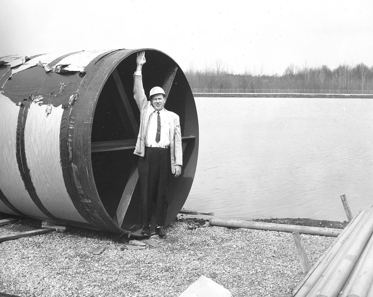
At its founding, the Marshall Space Flight Center (MSFC) inherited the Army’s Jupiter and Redstone test stands, but much larger facilities were needed for the giant stages of the Saturn V. From 1960 to 1964, the existing stands were remodeled and a sizable new test area was developed. The new comprehensive test complex for propulsion and structural dynamics was unique within the nation and the free world, and they remain so today because they were constructed with foresight to meet the future as well as on going needs. Construction of the S-IC Static test stand complex began in 1961 in the west test area of MSFC, and was completed in 1964. The S-IC static test stand was designed to develop and test the 138-ft long and 33-ft diameter Saturn V S-IC first stage, or booster stage, weighing in at 280,000 pounds. Required to hold down the brute force of a 7,500,000-pound thrust produced by 5 F-1 engines, the S-IC static test stand was designed and constructed with the strength of hundreds of tons of steel and 12,000,000 pounds of cement, planted down to bedrock 40 feet below ground level. The foundation walls, constructed with concrete and steel, are 4 feet thick. The base structure consists of four towers with 40-foot-thick walls extending upward 144 feet above ground level. The structure was topped by a crane with a 135-foot boom. With the boom in the upright position, the stand was given an overall height of 405 feet, placing it among the highest structures in Alabama at the time. In addition to the stand itself, related facilities were constructed during this time. Built directly east of the test stand was the Block House, which served as the control center for the test stand. The two were connected by a narrow access tunnel which housed the cables for the controls. Again to the east, just south of the Block House, was a newly constructed Pump House. Its function was to provide water to the stand to prevent melting damage during testing. The water was sprayed through small holes in the stand’s 1900 ton water deflector at the rate of 320,000 gallons per minute. In this photo, NASA employee Orville Driver is demonstrating the size of the 8 foot diameter water lines used for this purpose.
ISS037-E-010433 (11 Oct. 2013) --- Russian cosmonaut Sergey Ryazanskiy, Expedition 37 flight engineer, works with a Russian Orlan spacesuit in the Pirs Docking Compartment of the International Space Station.
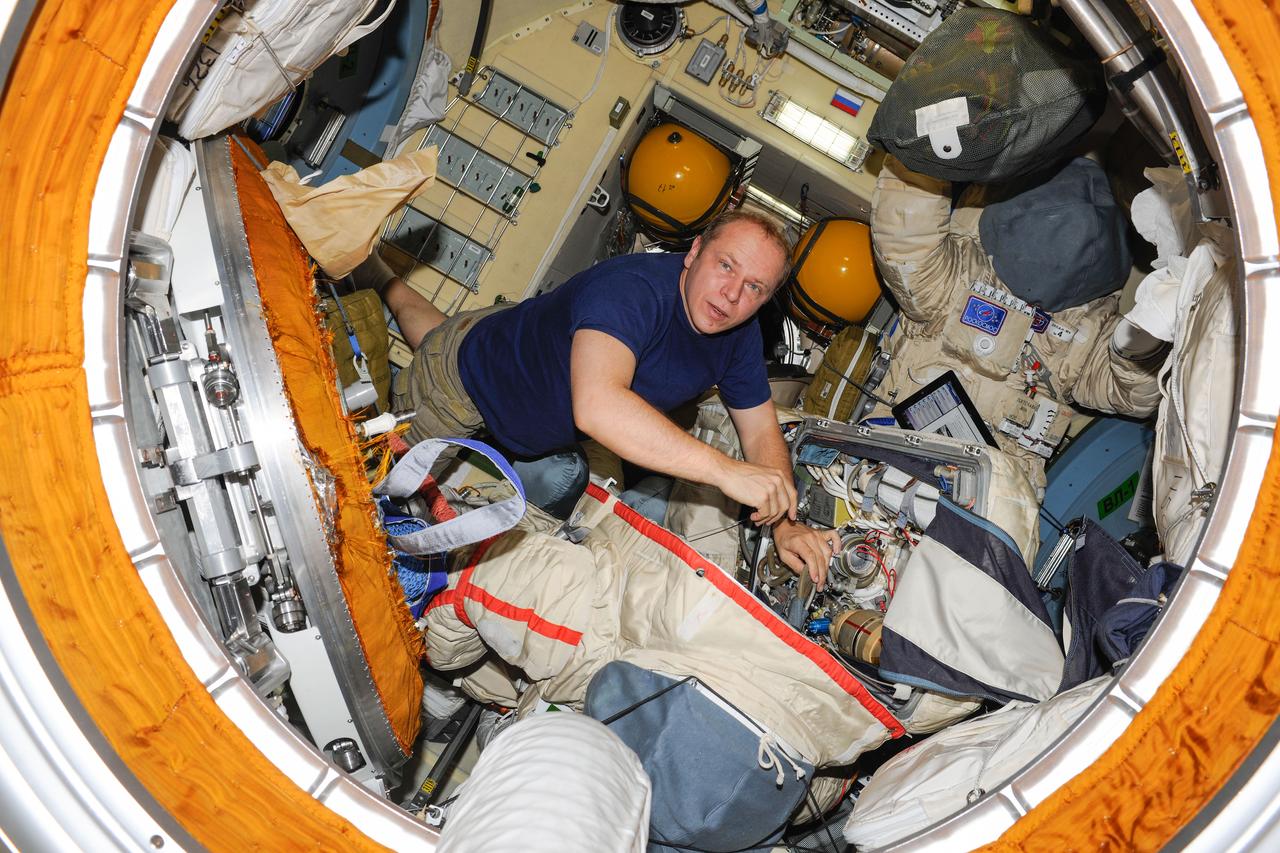
ISS037-E-010421 (11 Oct. 2013) --- Russian cosmonaut Oleg Kotov, Expedition 37 flight engineer, works with a Russian Orlan spacesuit in the Pirs Docking Compartment of the International Space Station.

Recent sea-level height data from NASA U.S./France Jason altimetric satellite during a 10-day cycle ending November 15, 2004.
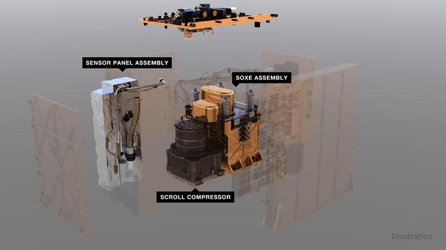
An illustration of MOXIE (Mars Oxygen ISRU Experiment) and its components. An air pump pulls in carbon dioxide gas from the Martian atmosphere, which is then regulated and fed to the Solid OXide Electrolyzer (SOXE), where it is electrochemically split to produce pure oxygen. https://photojournal.jpl.nasa.gov/catalog/PIA24177
Heart Pump
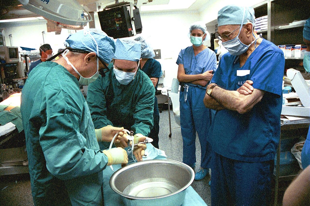
JSC2004-E-26519 --- Dr. Michael DeBakey (far right) observes preparation procedures before the implantation of a MicroMed DeBakey VAD® (ventricular assist device). The revolutionary heart pump received FDA approval in February 2004 for use in critically ill children awaiting heart transplants. The heart pump was designed with the help of NASA engineers who began working with Dr. DeBakey on the pump's development in the mid-1980s.

This image from NASA Spitzer and GALEX shows the Helix nebula, a dying star throwing a cosmic tantrum. In death, the star dusty outer layers are unraveling into space, glowing from the intense UV radiation being pumped out by the hot stellar core.
ISS039-E-013158 (18 April 2014) --- In the U.S. lab Destiny on the Earth-orbiting International Space Station, Expedition 39 Flight Engineer Steve Swanson of NASA works on WRS condensate pumping, using the high flow water transfer pump.
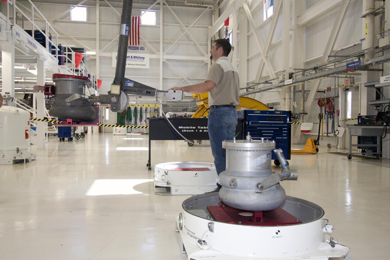
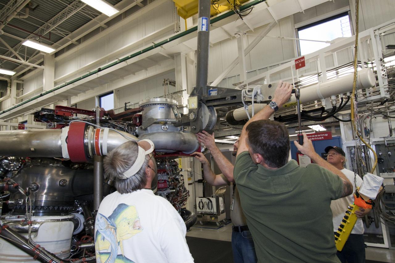
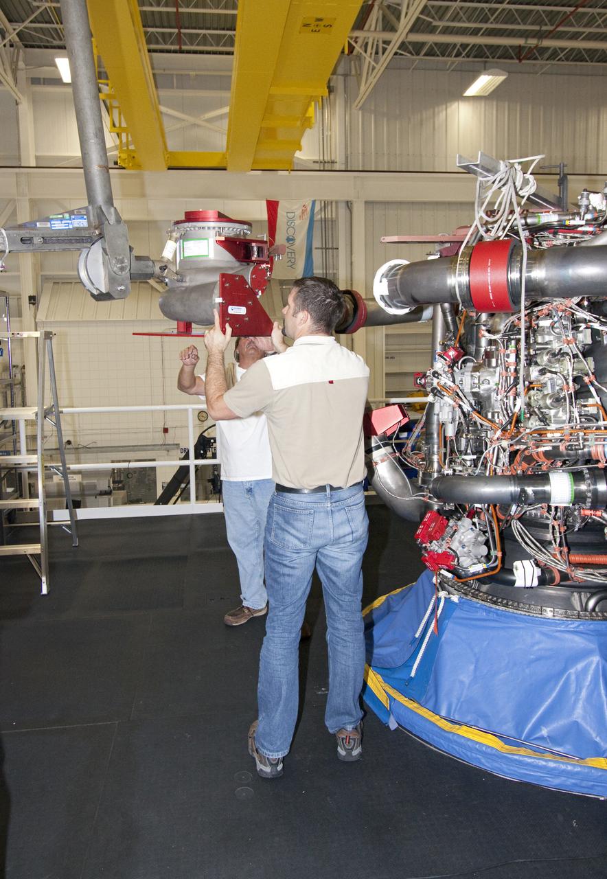
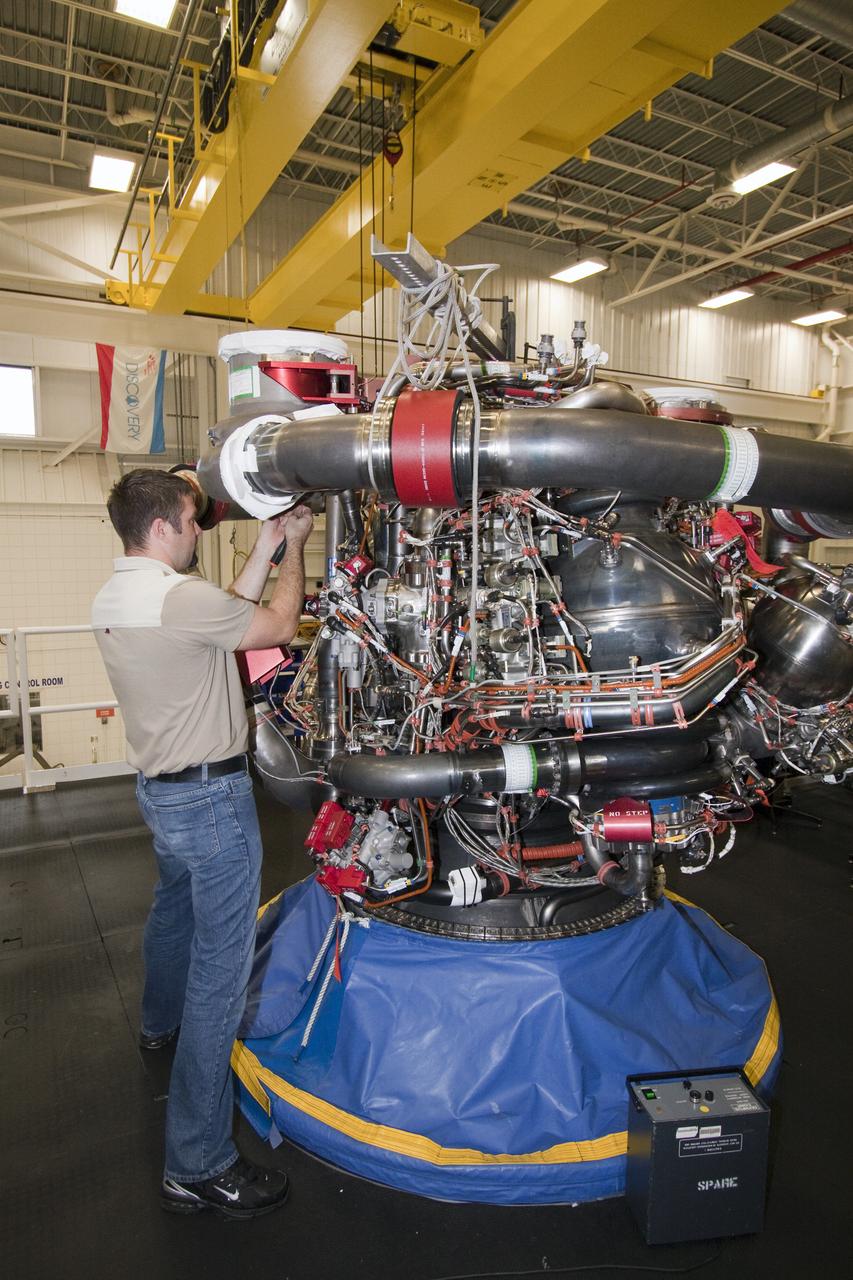
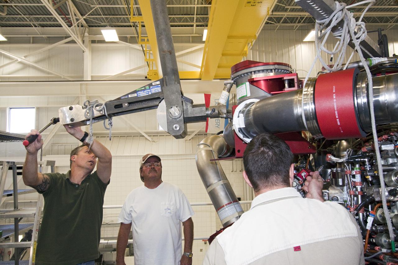
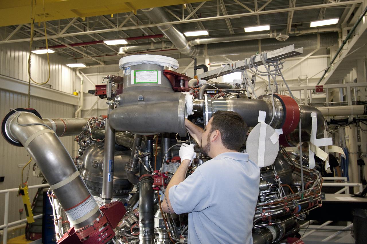
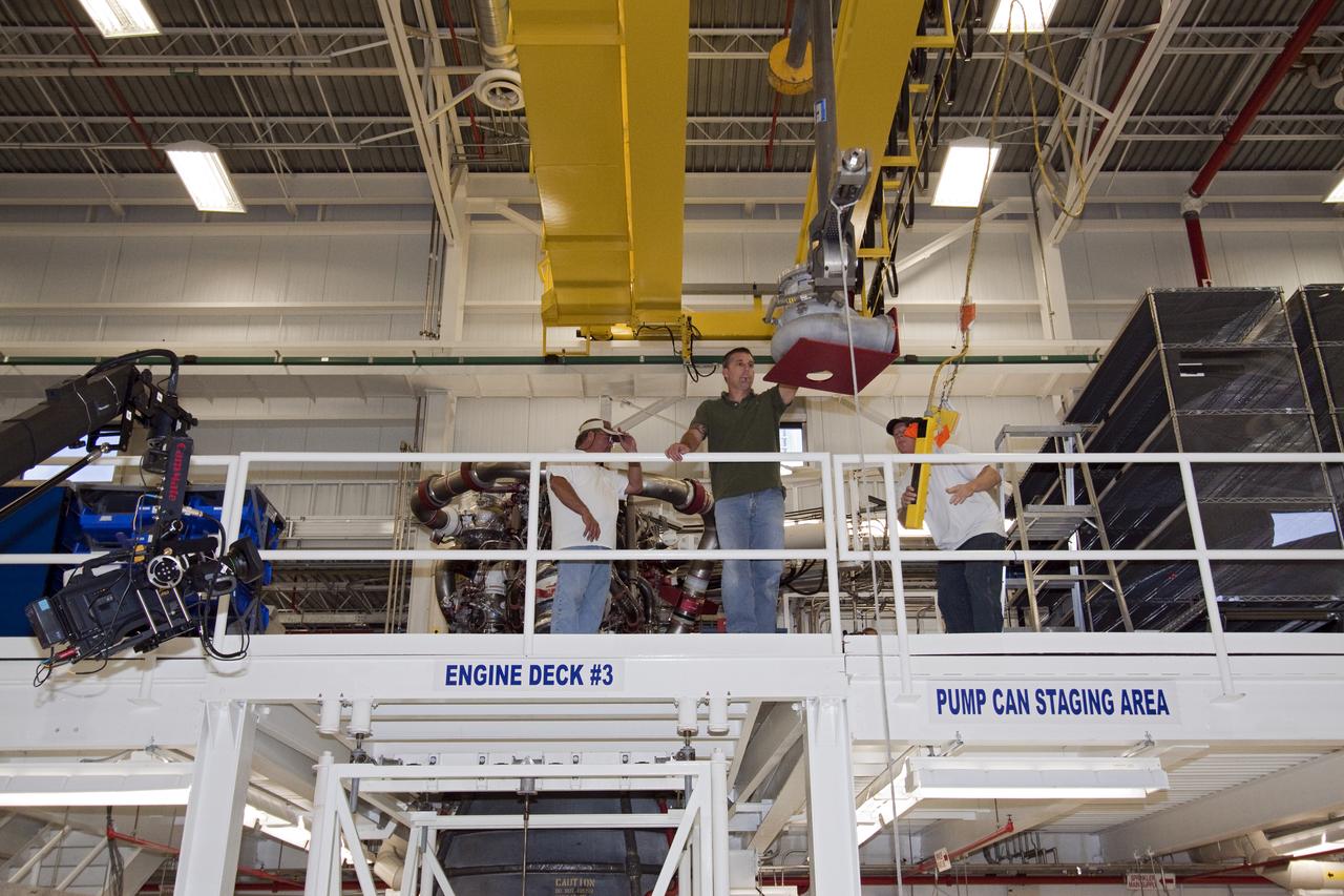
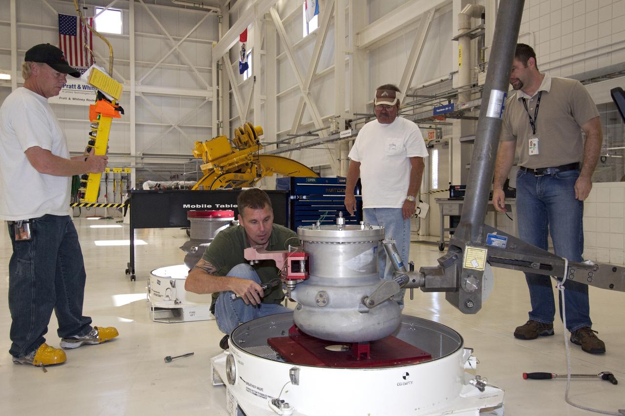
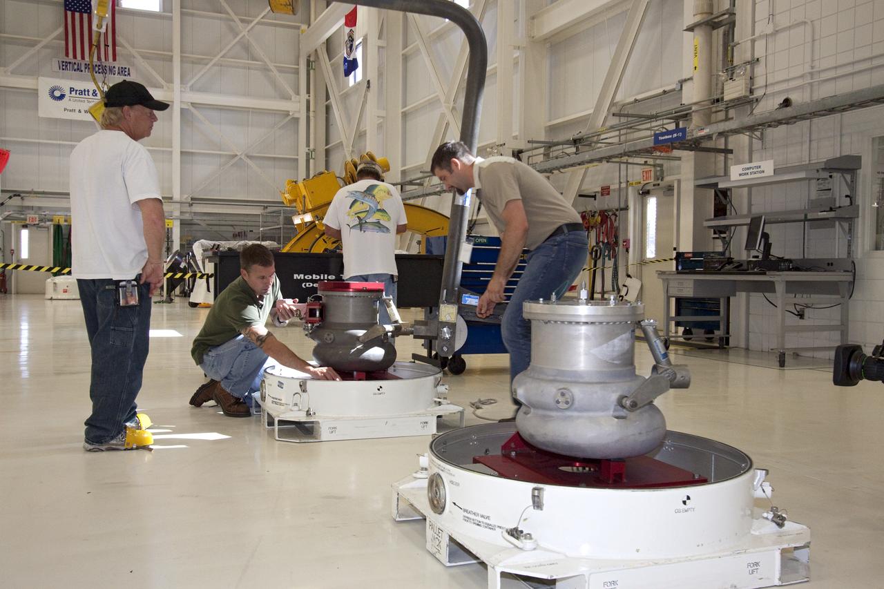
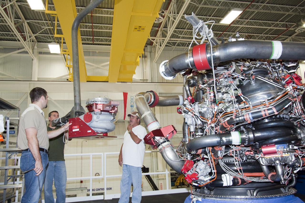
STS-133 DISCOVERY ENGINE-1 TURBO PUMP REMOVAL
STS-133 DISCOVERY ENGINE-1 TURBO PUMP REMOVAL
STS-133 DISCOVERY ENGINE-1 TURBO PUMP REMOVAL
STS-133 DISCOVERY ENGINE-1 TURBO PUMP REMOVAL
STS-133 DISCOVERY ENGINE-1 TURBO PUMP REMOVAL
STS-133 DISCOVERY ENGINE-1 TURBO PUMP REMOVAL
STS-133 DISCOVERY ENGINE-1 TURBO PUMP REMOVAL
STS-133 DISCOVERY ENGINE-1 TURBO PUMP REMOVAL
STS-133 DISCOVERY ENGINE-1 TURBO PUMP REMOVAL
STS-133 DISCOVERY ENGINE-1 TURBO PUMP REMOVAL
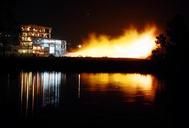
Gaseous hydrogen is burned off at the E1 Test Stand the night of Oct. 7 during a cold-flow test of the fuel turbopump of the Integrated Powerhead Demonstrator (IPD) at NASA Stennis Space Center (SSC). The gaseous hydrogen spins the pump's turbine during the test, which was conducted to verify the pump's performance. Engineers plan one more test before sending the pump to The Boeing Co. for inspection. It will then be returned to SSC for engine system assembly. The IPD is the first reusable hydrogen-fueled advanced engine in development since the Space Shuttle Main Engine.
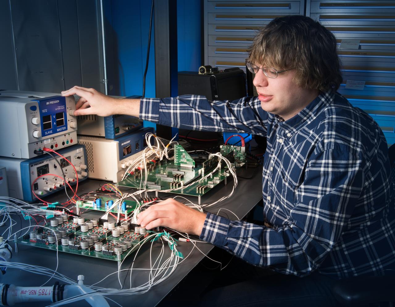
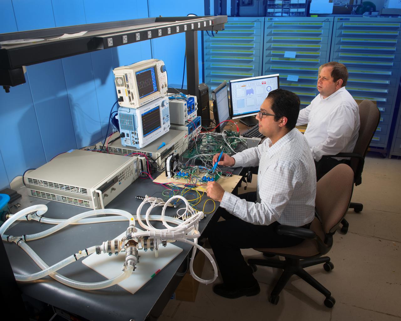
Environmental Portrait of a Telecommunications Engineer with the University of Indiana Heart Pump, Motor Controller Electronics
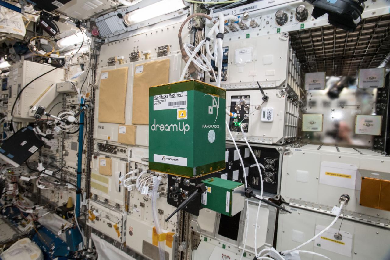
iss057e105655 (11/21/2018) --- A view of the Pump Application using Pulsed Electromagnets for Liquid reLocation (PAPELL) - NanoRacks Module-76 experiment which examines the behavior of special magnetic fluid transport systems to determine how these systems perform in space. PAPELL uses cameras and other automated equipment to monitor exactly how ferrofluids travel across grids of electromagnets and through pipes when manipulated with an electromagnetic field under a range of different conditions. The results will contribute to the development of a low wear, low maintenance pumping system.
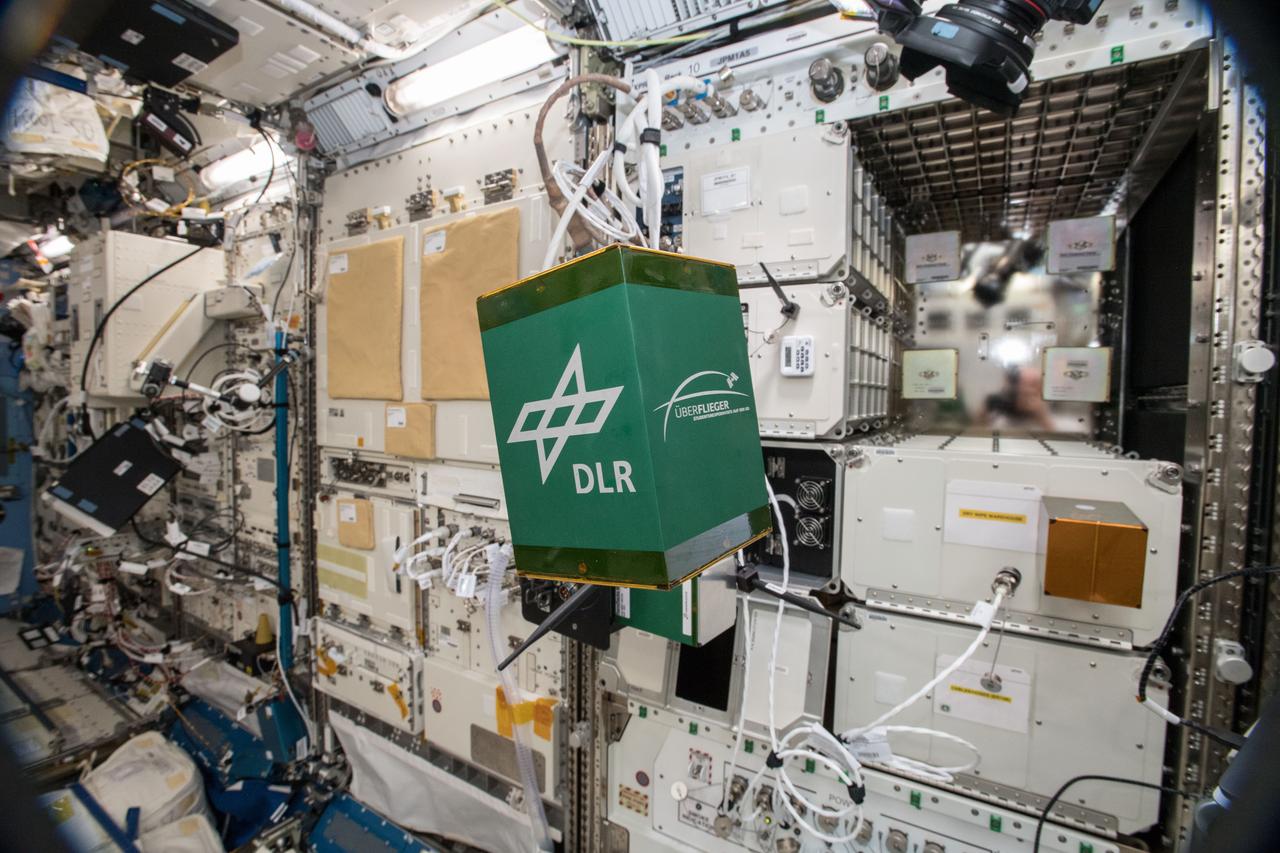
iss057e105652 (11/21/2018) --- A view of the Pump Application using Pulsed Electromagnets for Liquid reLocation (PAPELL) - NanoRacks Module-76 experiment which examines the behavior of special magnetic fluid transport systems to determine how these systems perform in space. PAPELL uses cameras and other automated equipment to monitor exactly how ferrofluids travel across grids of electromagnets and through pipes when manipulated with an electromagnetic field under a range of different conditions. The results will contribute to the development of a low wear, low maintenance pumping system.
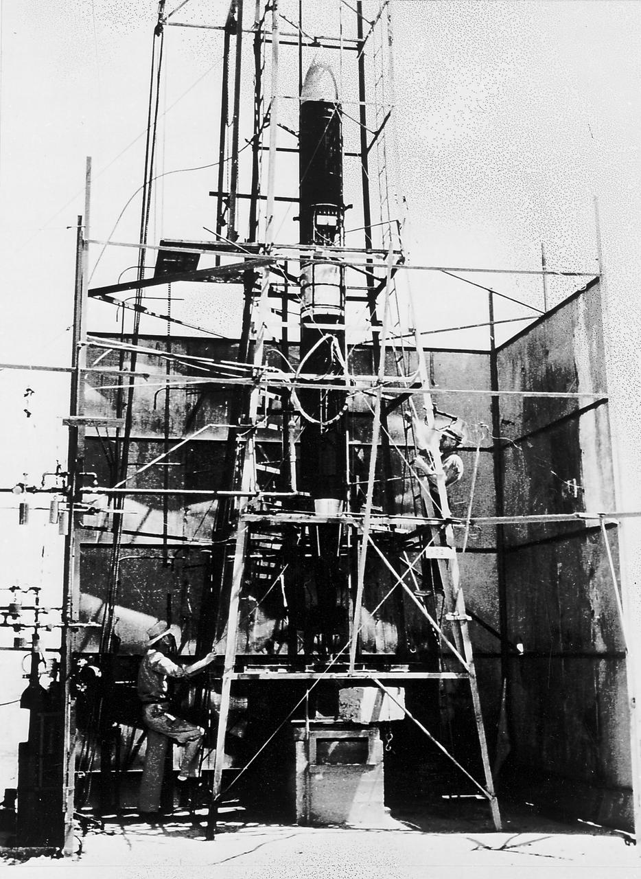
Goddard rocket in launching tower at Roswell, New Mexico, March 21, 1940. Fuel was injected by pumps from the fueling platform at left. From 1930 to 1941, Dr. Goddard made substantial progress in the development of progressively larger rockets, which attained altitudes of 2400 meters, and refined his equipment for guidance and control, his techniques of welding, and his insulation, pumps, and other associated equipment. In many respects, Dr. Goddard laid the essential foundations of practical rocket technology
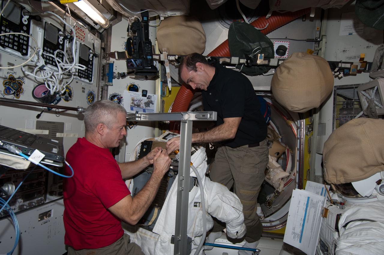
Expedition 39 flight engineers Steve Swanson and Rick Mastracchio work to remove and replace the Fan Pump Separator (FPS) on Extravehicular Mobility Unit (EMU) 3005. Image was taken in the Quest Airlock (A/L) and was released by Swanson on Instagram.
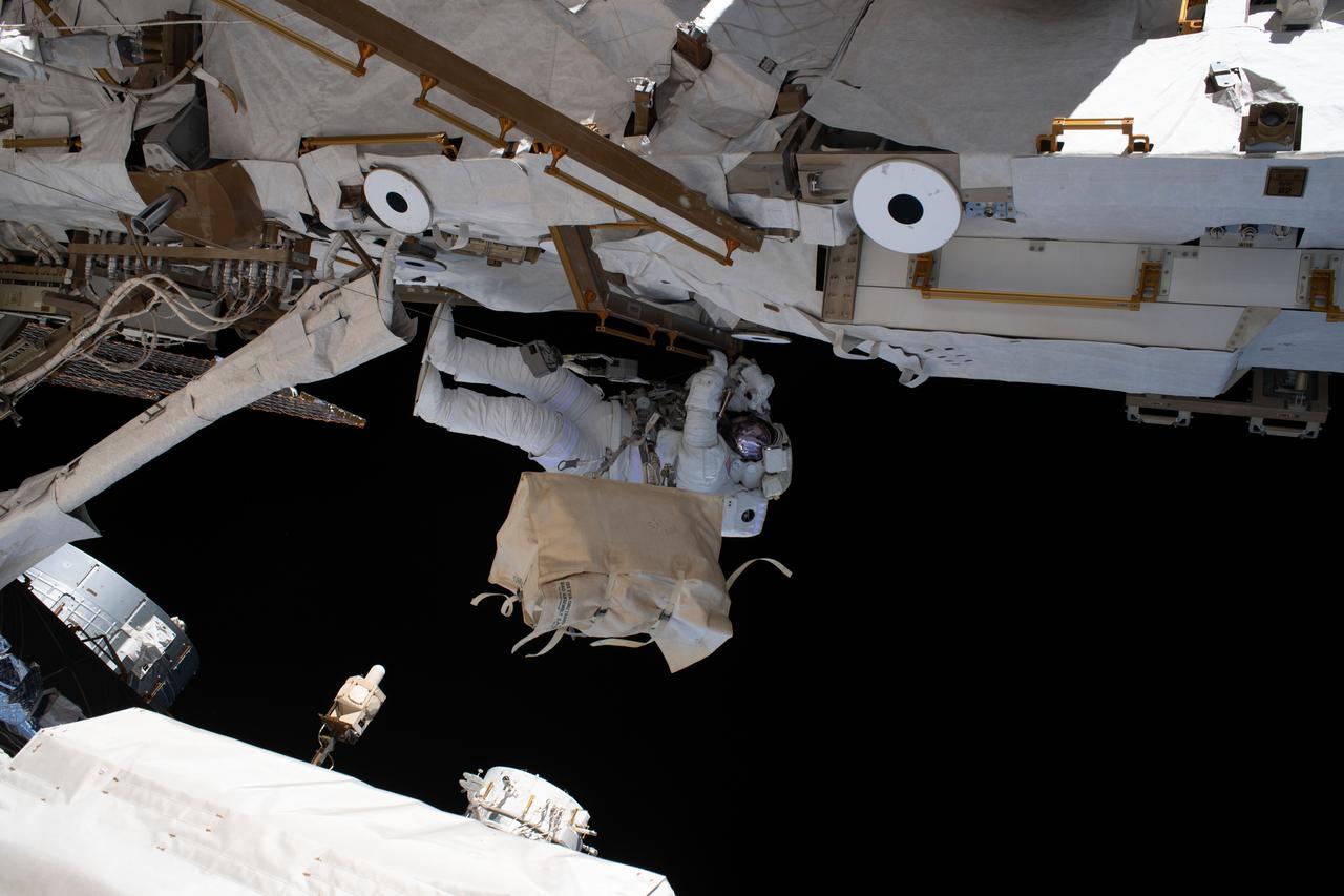
iss061e066433 (Dec. 2, 2019) --- NASA astronaut Andrew Morgan is tethered to the International Space Station during the third spacewalk to upgrade the Alpha Magnetic Spectrometer's thermal pump system.
ISS029-E-007893 (23 Sept. 2011) --- NASA astronaut Mike Fossum, Expedition 29 commander, works with the Water Recovery System (WRS) Fluids Control and Pump Assembly (FCPA) in the Destiny laboratory of the International Space Station.
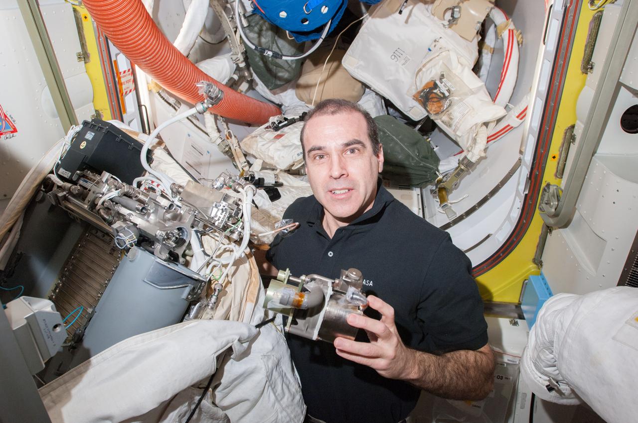
Expedition 39 flight engineer Rick Mastracchio poses for a photo with the replacement Fan Pump Separator (FPS) and Extravehicular Mobility Unit (EMU) 3005. Image was taken in the Quest Airlock (A/L) during FPS remove and replace operations.
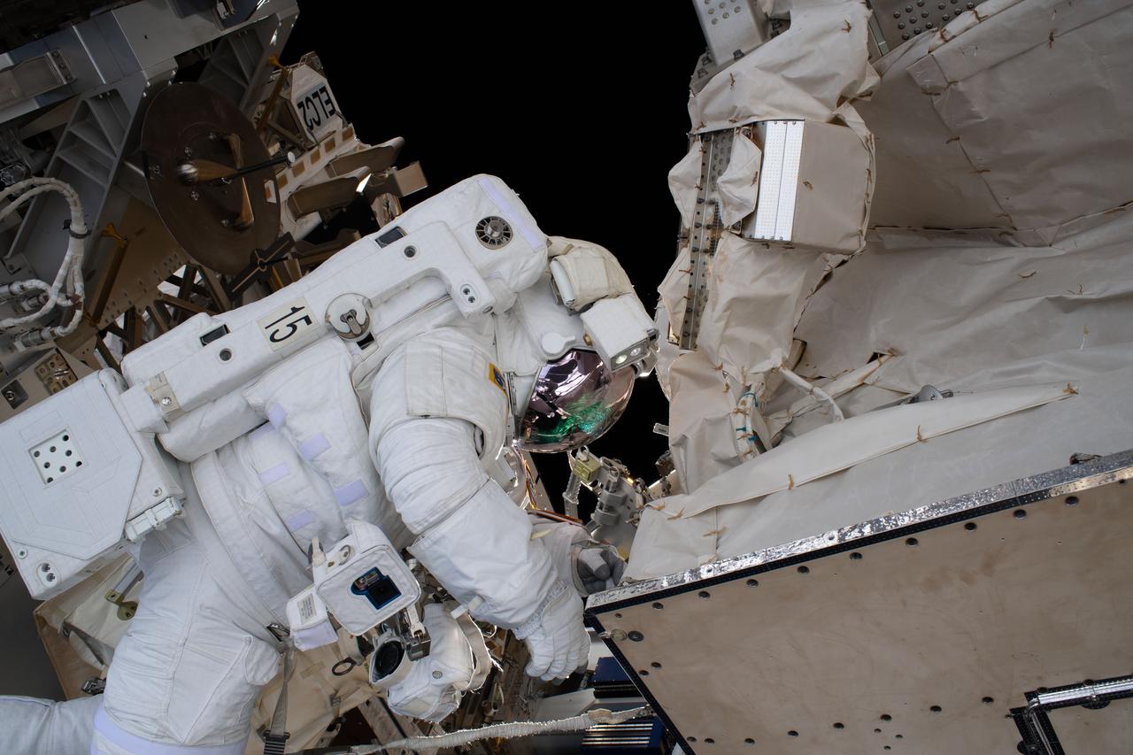
iss061e065826 (Dec. 2, 2019) --- NASA astronaut Andrew Morgan is tethered to the International Space Station during the third spacewalk to upgrade the Alpha Magnetic Spectrometer's thermal pump system.
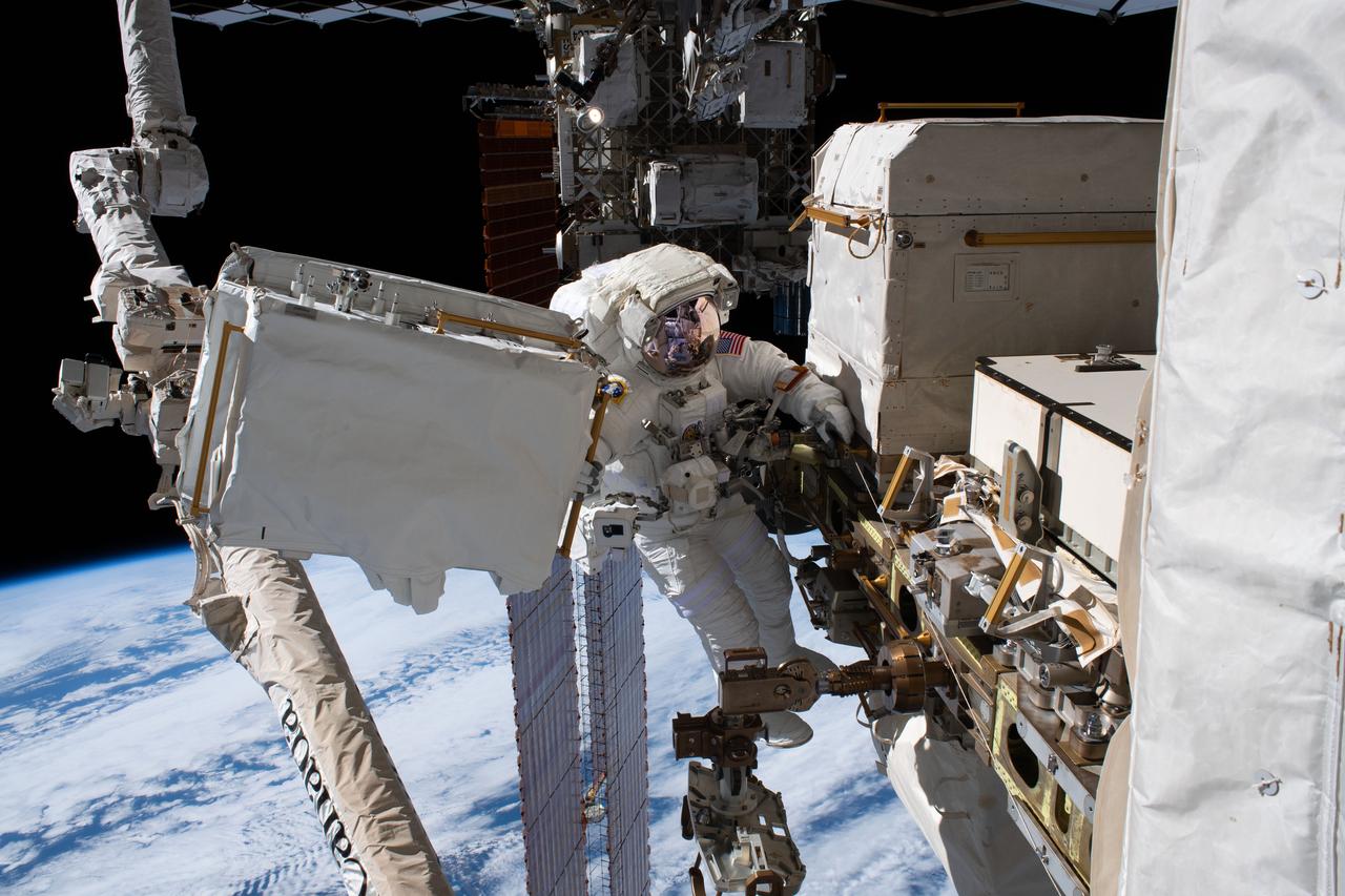
iss061e065379 (Dec. 2, 2019) --- NASA astronaut Andrew Morgan is tethered to the International Space Station with the Earth 250 miles below during the third spacewalk to upgrade the Alpha Magnetic Spectrometer's thermal pump system.
ISS029-E-007892 (23 Sept. 2011) --- NASA astronaut Mike Fossum, Expedition 29 commander, works with the Water Recovery System (WRS) Fluids Control and Pump Assembly (FCPA) in the Destiny laboratory of the International Space Station.
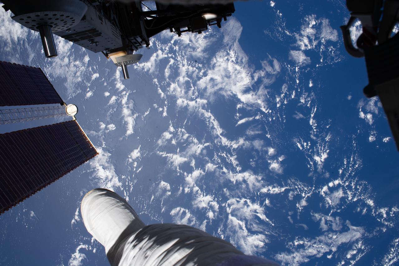
iss061e064798 (Dec. 2, 2019) --- NASA astronaut Andrew Morgan photographed the Earth 250 miles below him, with his foot in the foreground, during the third spacewalk to upgrade the Alpha Magnetic Spectrometer's thermal pump system.

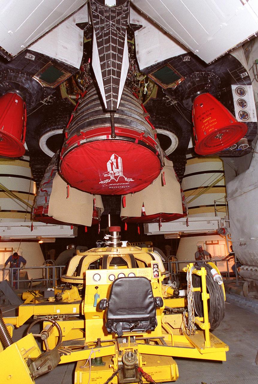
KENNEDY SPACE CENTER, FLA. -- In the Vehicle Assembly Building, Space Shuttle Atlantis' Main Engine No. 1 is lowered after its removal. An inventory review concerning defective main engine fuel pump tip seals indicated that defective seals may be present on the fuel pump for the engine. The decision was made to replace the suspect engine with one originally slated for Discovery. The main engine nozzle, visible in the photo, is 7.8 feet across and 9.4 feet high. Space Shuttle Atlantis is scheduled to launch no earlier than April 17, 2000, on mission STS-101 to resupply the International Space Station for the arrival of the next pressurized module, the Russian-built Zvezda

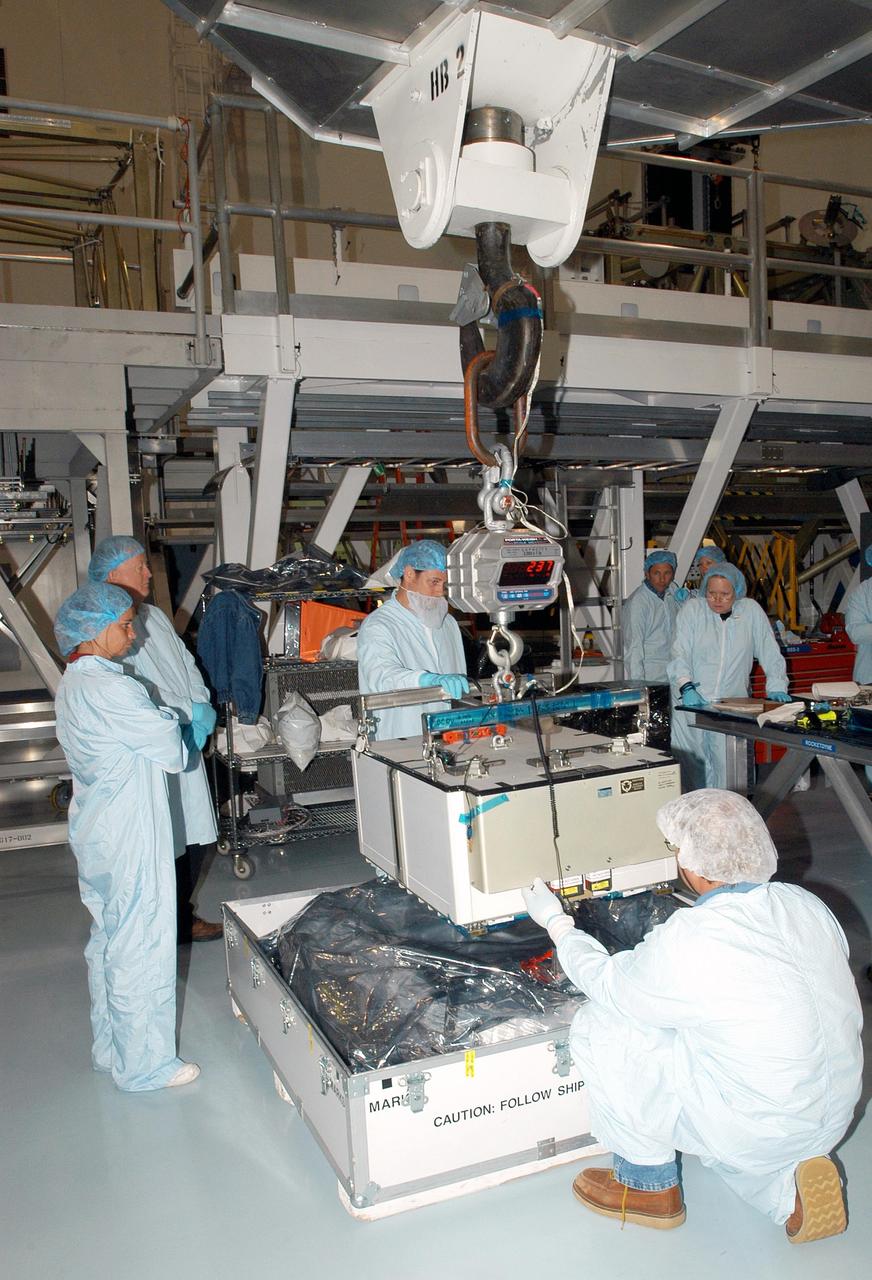
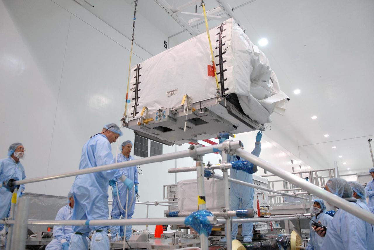
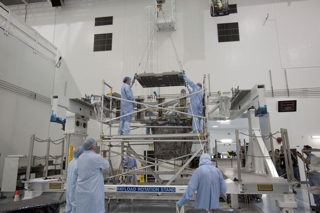
CAPE CANAVERAL, Fla. – In the space Station Processing Facility at NASA's Kennedy Space Center in Florida, the pump module orbital replacement unit will be fitted with a crane to lift it to the Express Logistics Carrier 1, or ELC-1. The carrier is part of the STS-129 payload on space shuttle Atlantis, which will deliver to the International Space Station two spare gyroscopes, two nitrogen tank assemblies, two pump modules, an ammonia tank assembly and a spare latching end effector for the station's robotic arm. STS-129 is targeted to launch Nov. 12. Photo credit: NASA/Jim Grossmann
CAPE CANAVERAL, Fla. – In the space Station Processing Facility at NASA's Kennedy Space Center in Florida, technicians prepare to attach the overhead crane to the pump module orbital replacement unit. The crane will lift and move the equipment to the Express Logistics Carrier 1, or ELC-1. The carrier is part of the STS-129 payload on space shuttle Atlantis, which will deliver to the International Space Station two spare gyroscopes, two nitrogen tank assemblies, two pump modules, an ammonia tank assembly and a spare latching end effector for the station's robotic arm. STS-129 is targeted to launch Nov. 12. Photo credit: NASA/Jim Grossmann
CAPE CANAVERAL, Fla. – In the space Station Processing Facility at NASA's Kennedy Space Center in Florida, the pump module orbital replacement unit is lowered toward the Express Logistics Carrier 1, or ELC-1, for installation. The carrier is part of the STS-129 payload on space shuttle Atlantis, which will deliver to the International Space Station two spare gyroscopes, two nitrogen tank assemblies, two pump modules, an ammonia tank assembly and a spare latching end effector for the station's robotic arm. STS-129 is targeted to launch Nov. 12. Photo credit: NASA/Jim Grossmann
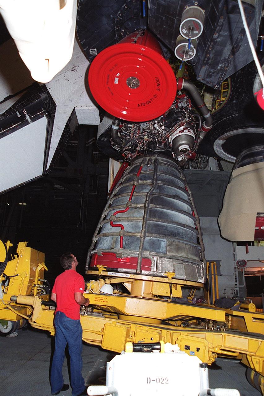
KENNEDY SPACE CENTER, FLA. -- In the Vehicle Assembly Building, Space Shuttle Atlantis' Main Engine No. 1 is lowered onto a transporter. The engine was removed because an inventory review concerning defective main engine fuel pump tip seals indicated that defective seals may be present on the fuel pump for the engine. The decision was made to replace the suspect engine with one originally slated for Discovery. The main engine nozzle, visible in the photo, is 7.8 feet across and 9.4 feet high. Space Shuttle Atlantis is scheduled to launch no earlier than April 17, 2000, on mission STS-101 to resupply the International Space Station for the arrival of the next pressurized module, the Russian-built Zvezda
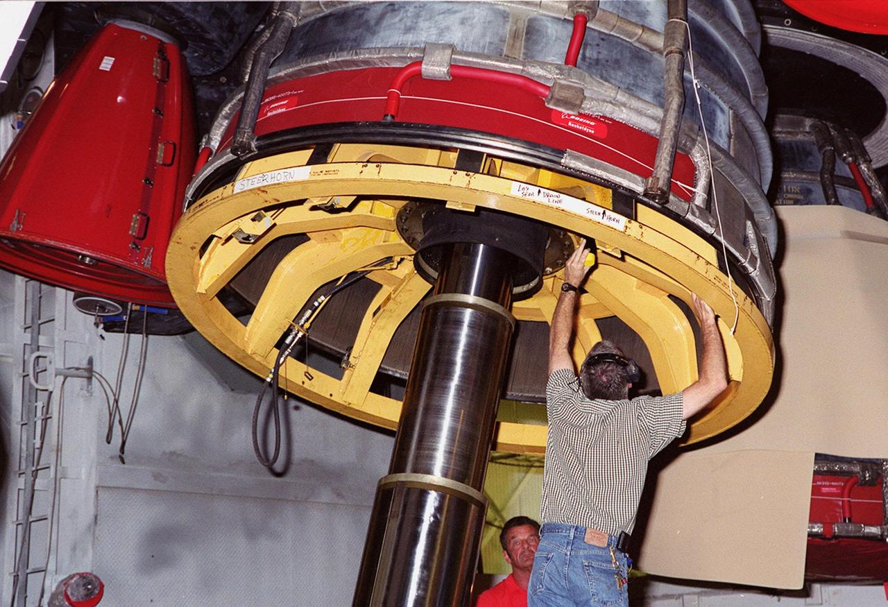
KENNEDY SPACE CENTER, FLA. -- A worker in the Vehicle Assembly Building adjusts the equipment being used for the removal of Main Engine No. 1 on Space Shuttle Atlantis. An inventory review concerning defective main engine fuel pump tip seals indicated that defective seals may be present on the fuel pump for the engine. The decision was made to replace the suspect engine with one originally slated for Discovery. The main engine nozzle, visible in the photo, is 7.8 feet across and 9.4 feet high. Space Shuttle Atlantis is scheduled to launch no earlier than April 17, 2000, on mission STS-101 to resupply the International Space Station for the arrival of the next pressurized module, the Russian-built Zvezda
KENNEDY SPACE CENTER, FLA. -- In the Vehicle Assembly Building, Space Shuttle Atlantis' Main Engine No. 1 sits on a transporter after being removed. An inventory review concerning defective main engine fuel pump tip seals indicated that defective seals may be present on the fuel pump for the engine. The decision was made to replace the suspect engine with one originally slated for Discovery. The main engine nozzle, visible in the photo, is 7.8 feet across and 9.4 feet high. Space Shuttle Atlantis is scheduled to launch no earlier than April 17, 2000, on mission STS-101 to resupply the International Space Station for the arrival of the next pressurized module, the Russian-built Zvezda
KENNEDY SPACE CENTER, FLA. -- A replacement engine is installed in Space Shuttle Atlantis. Main Engine No. 1 was removed after an inventory review concerning defective main engine fuel pump tip seals indicated that defective seals might be present on the previous fuel pump for the engine. The decision was made to replace the suspect engine with one originally slated for Discovery. The main engine nozzle, visible in the photo, is 7.8 feet across and 9.4 feet high. Space Shuttle Atlantis is scheduled to launch no earlier than April 17, 2000, on mission STS-101 to resupply the International Space Station for the arrival of the next pressurized module, the Russian-built Zvezda
KENNEDY SPACE CENTER, FLA. -- The equipment is in place to remove Main Engine No. 1 from Space Shuttle Atlantis in the Vehicle Assembly Building. An inventory review concerning defective main engine fuel pump tip seals indicated that defective seals may be present on the fuel pump for the engine. The decision was made to replace the suspect engine with one originally slated for Discovery. The main engine nozzles, visible in the photo, are 7.8 feet across and 9.4 feet high. Space Shuttle Atlantis is scheduled to launch no earlier than April 17, 2000, on mission STS-101 to resupply the International Space Station for the arrival of the next pressurized module, the Russian-built Zvezda

KENNEDY SPACE CENTER, FLA. -- In the Vehicle Assembly Building, Space Shuttle Atlantis' Main Engine No. 1 sits on a transporter after being removed. An inventory review concerning defective main engine fuel pump tip seals indicated that defective seals may be present on the fuel pump for the engine. The decision was made to replace the suspect engine with one originally slated for Discovery. The main engine nozzle, visible in the photo, is 7.8 feet across and 9.4 feet high. Space Shuttle Atlantis is scheduled to launch no earlier than April 17, 2000, on mission STS-101 to resupply the International Space Station for the arrival of the next pressurized module, the Russian-built Zvezda

KENNEDY SPACE CENTER, FLA. -- A worker in the Vehicle Assembly Building adjusts the equipment being used for the removal of Main Engine No. 1 on Space Shuttle Atlantis. An inventory review concerning defective main engine fuel pump tip seals indicated that defective seals may be present on the fuel pump for the engine. The decision was made to replace the suspect engine with one originally slated for Discovery. The main engine nozzle, visible in the photo, is 7.8 feet across and 9.4 feet high. Space Shuttle Atlantis is scheduled to launch no earlier than April 17, 2000, on mission STS-101 to resupply the International Space Station for the arrival of the next pressurized module, the Russian-built Zvezda

KENNEDY SPACE CENTER, FLA. -- In the Vehicle Assembly Building, Space Shuttle Atlantis' Main Engine No. 1 is lowered onto a transporter. The engine was removed because an inventory review concerning defective main engine fuel pump tip seals indicated that defective seals may be present on the fuel pump for the engine. The decision was made to replace the suspect engine with one originally slated for Discovery. The main engine nozzle, visible in the photo, is 7.8 feet across and 9.4 feet high. Space Shuttle Atlantis is scheduled to launch no earlier than April 17, 2000, on mission STS-101 to resupply the International Space Station for the arrival of the next pressurized module, the Russian-built Zvezda
CAPE CANAVERAL, Fla. – In the space Station Processing Facility at NASA's Kennedy Space Center in Florida, the pump module orbital replacement unit is lowered toward the Express Logistics Carrier 1, or ELC-1, for installation. The carrier is part of the STS-129 payload on space shuttle Atlantis, which will deliver to the International Space Station two spare gyroscopes, two nitrogen tank assemblies, two pump modules, an ammonia tank assembly and a spare latching end effector for the station's robotic arm. STS-129 is targeted to launch Nov. 12. Photo credit: NASA/Jim Grossmann
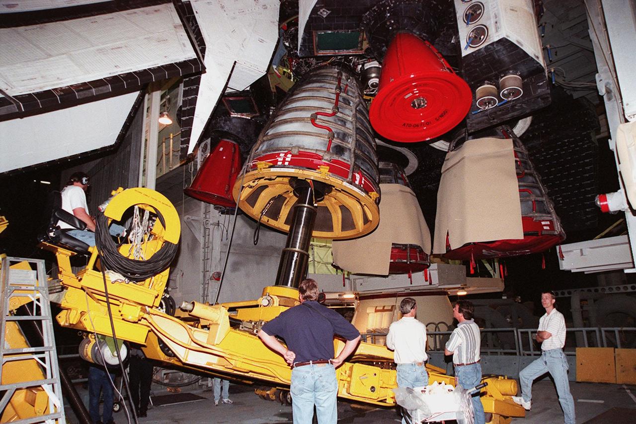
KENNEDY SPACE CENTER, FLA. -- Workers in the Vehicle Assembly Building oversee the replacement of Main Engine No. 1 in Space Shuttle Atlantis (overhead). An inventory review concerning defective main engine fuel pump tip seals indicated that defective seals might be present on the previous fuel pump for the engine. The decision was made to replace the suspect engine with one originally slated for Discovery. The main engine nozzle, visible in the photo, is 7.8 feet across and 9.4 feet high. Space Shuttle Atlantis is scheduled to launch no earlier than April 17, 2000, on mission STS-101 to resupply the International Space Station for the arrival of the next pressurized module, the Russian-built Zvezda
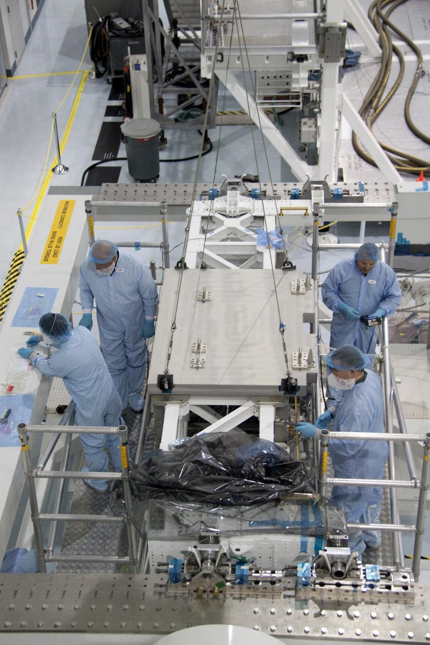
CAPE CANAVERAL, Fla. - In the Space Station Processing Facility at NASA's Kennedy Space Center in Florida, technicians secure the pump module assembly plate into position onto the Lightweight Multi-Purpose Experiment Support Structure Carrier, or LMC. The module assembly will be used to secure the return of a failed ammonia pump module in shuttle Atlantis' payload bay. Atlantis and its payload are being prepared for the STS-135 mission, which will deliver the Raffaello multipurpose logistics module packed with supplies, logistics and spare parts to the International Space Station. STS-135 is targeted to launch June 28, and will be the last spaceflight for the Space Shuttle Program. Photo credit: NASA/Jack Pfaller
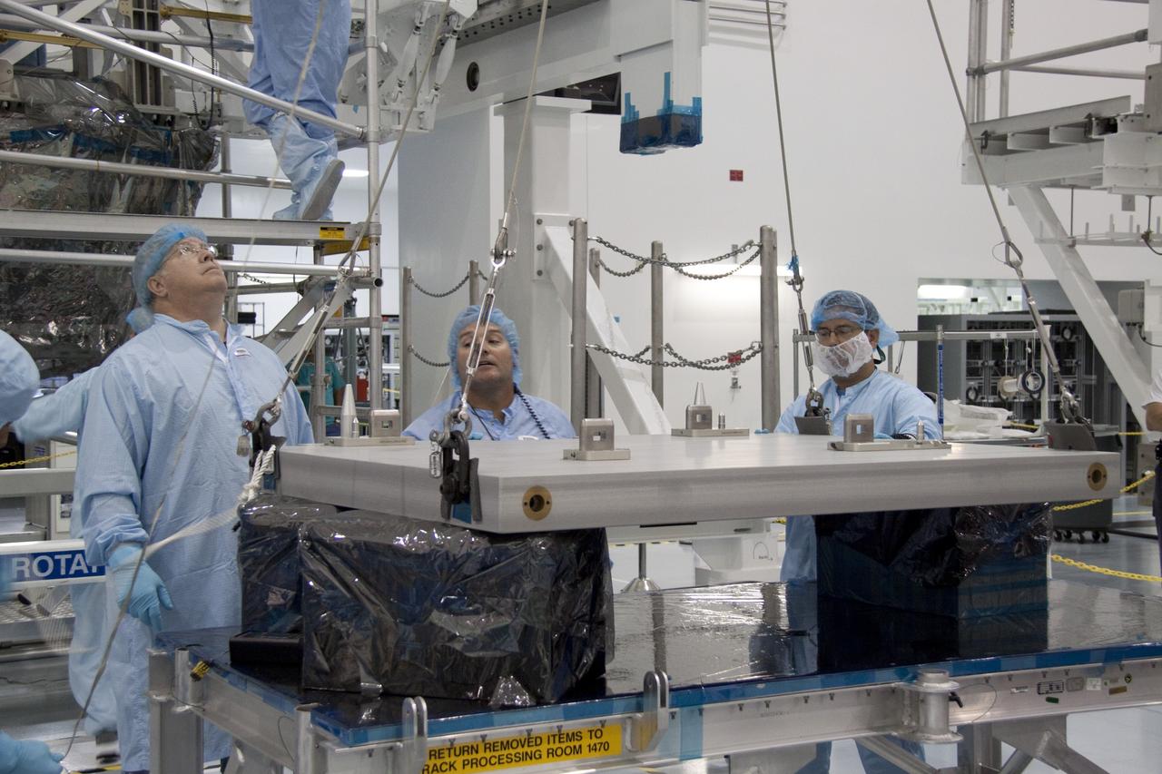
CAPE CANAVERAL, Fla. - In the Space Station Processing Facility at NASA's Kennedy Space Center in Florida, technicians monitor the progress of an overhead crane as it lifts the pump module assembly plate for transfer to the Lightweight Multi-Purpose Experiment Support Structure Carrier, or LMC. The module assembly will be used to secure the return of a failed ammonia pump module in shuttle Atlantis' payload bay. Atlantis and its payload are being prepared for the STS-135 mission, which will deliver the Raffaello multipurpose logistics module packed with supplies, logistics and spare parts to the International Space Station. STS-135 is targeted to launch June 28, and will be the last spaceflight for the Space Shuttle Program. Photo credit: NASA/Jack Pfaller
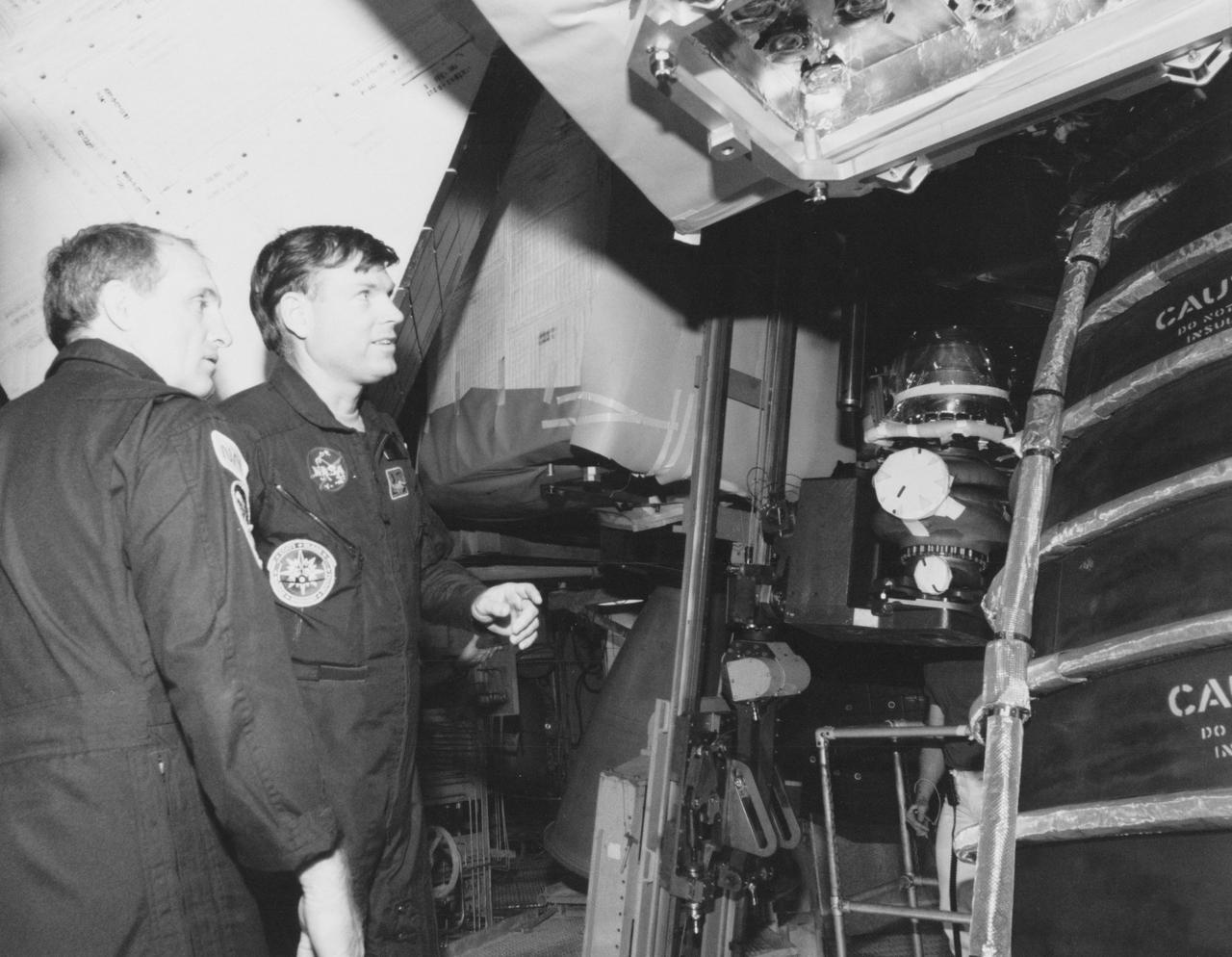
S89-28091 (7 Feb 1989) --- STS-29 astronauts inspect an area near the three main engines of the Space Shuttle Discovery prior to the removal of one of three oxidozer turbo pumps. Left to right are Astronauts James F. Buchli, mission specialist, and Michael L. Coats, mission commander. New pumps are scheduled to be installed soon. Now at Launch Pad 39-B, Discovery is set for launch in mid-March for Mission STS-29. Primary payload will be TDRS-D. Crewmembers not seen here are John E. Blaha, the pilot; and Robert C. Springer and James P. Bagian, both mission specialists.

KENNEDY SPACE CENTER, FLA. -- Workers in the Vehicle Assembly Building oversee the replacement of Main Engine No. 1 in Space Shuttle Atlantis (overhead). An inventory review concerning defective main engine fuel pump tip seals indicated that defective seals might be present on the previous fuel pump for the engine. The decision was made to replace the suspect engine with one originally slated for Discovery. The main engine nozzle, visible in the photo, is 7.8 feet across and 9.4 feet high. Space Shuttle Atlantis is scheduled to launch no earlier than April 17, 2000, on mission STS-101 to resupply the International Space Station for the arrival of the next pressurized module, the Russian-built Zvezda
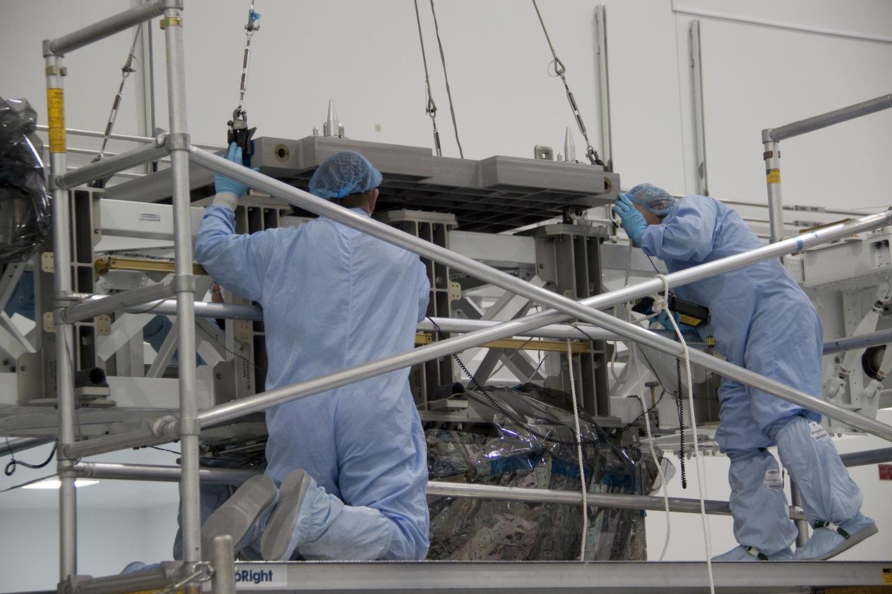
CAPE CANAVERAL, Fla. - In the Space Station Processing Facility at NASA's Kennedy Space Center in Florida, technicians guide an overhead crane as it lowers the pump module assembly plate toward the Lightweight Multi-Purpose Experiment Support Structure Carrier, or LMC. The module assembly will be used to secure the return of a failed ammonia pump module in shuttle Atlantis' payload bay. Atlantis and its payload are being prepared for the STS-135 mission, which will deliver the Raffaello multipurpose logistics module packed with supplies, logistics and spare parts to the International Space Station. STS-135 is targeted to launch June 28, and will be the last spaceflight for the Space Shuttle Program. Photo credit: NASA/Jack Pfaller
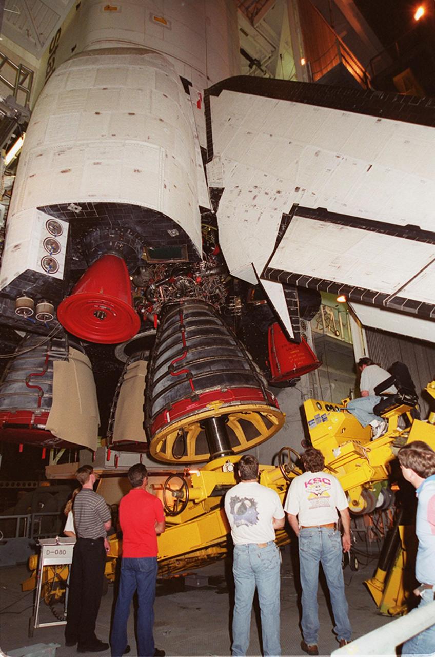
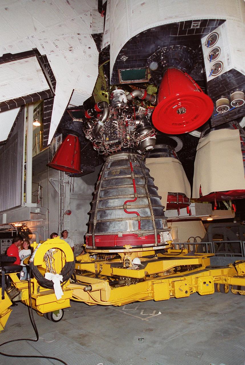
KENNEDY SPACE CENTER, FLA. -- Workers in the Vehicle Assembly Building watch as Space Shuttle Atlantis' Main Engine No. 1 is being removed. An inventory review concerning defective main engine fuel pump tip seals indicated that defective seals may be present on the fuel pump for the engine. The decision was made to replace the suspect engine with one originally slated for Discovery. The main engine nozzle, visible in the photo, is 7.8 feet across and 9.4 feet high. Space Shuttle Atlantis is scheduled to launch no earlier than April 17, 2000, on mission STS-101 to resupply the International Space Station for the arrival of the next pressurized module, the Russian-built Zvezda
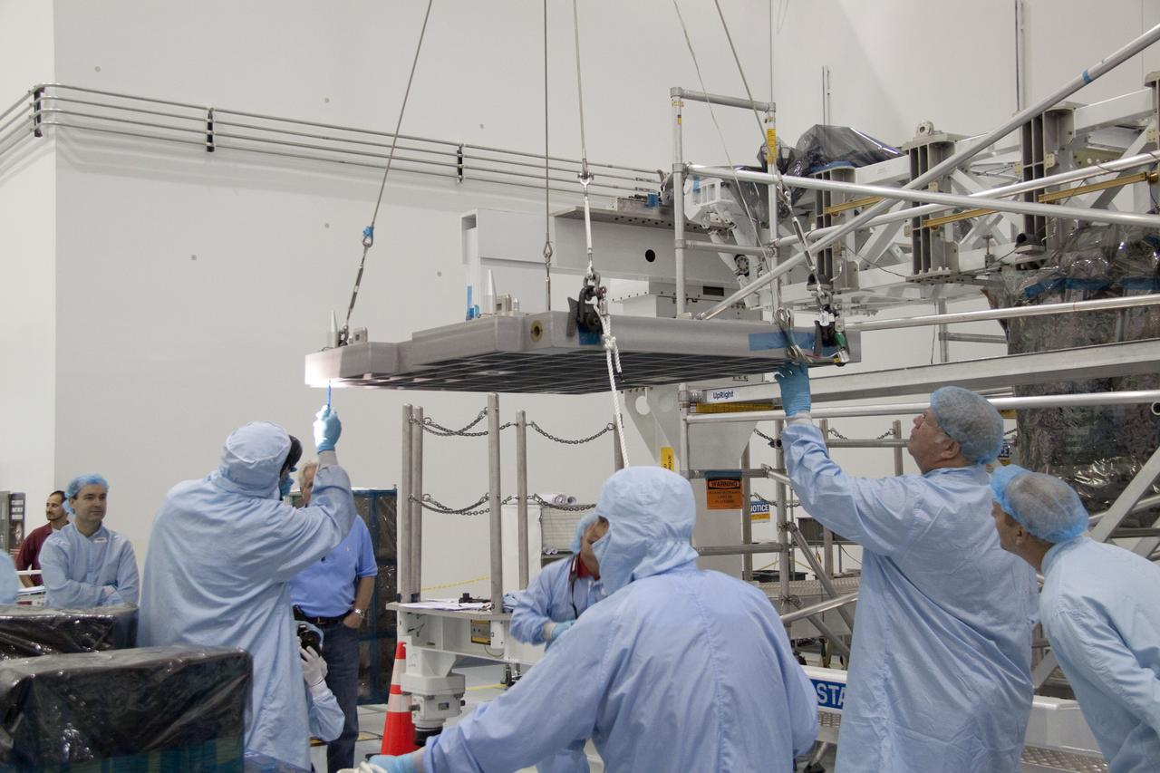
CAPE CANAVERAL, Fla. - In the Space Station Processing Facility at NASA's Kennedy Space Center in Florida, technicians guide an overhead crane as it lifts the pump module assembly plate for transfer to the Lightweight Multi-Purpose Experiment Support Structure Carrier, or LMC. The module assembly will be used to secure the return of a failed ammonia pump module in shuttle Atlantis' payload bay. Atlantis and its payload are being prepared for the STS-135 mission, which will deliver the Raffaello multipurpose logistics module packed with supplies, logistics and spare parts to the International Space Station. STS-135 is targeted to launch June 28, and will be the last spaceflight for the Space Shuttle Program. Photo credit: NASA/Jack Pfaller
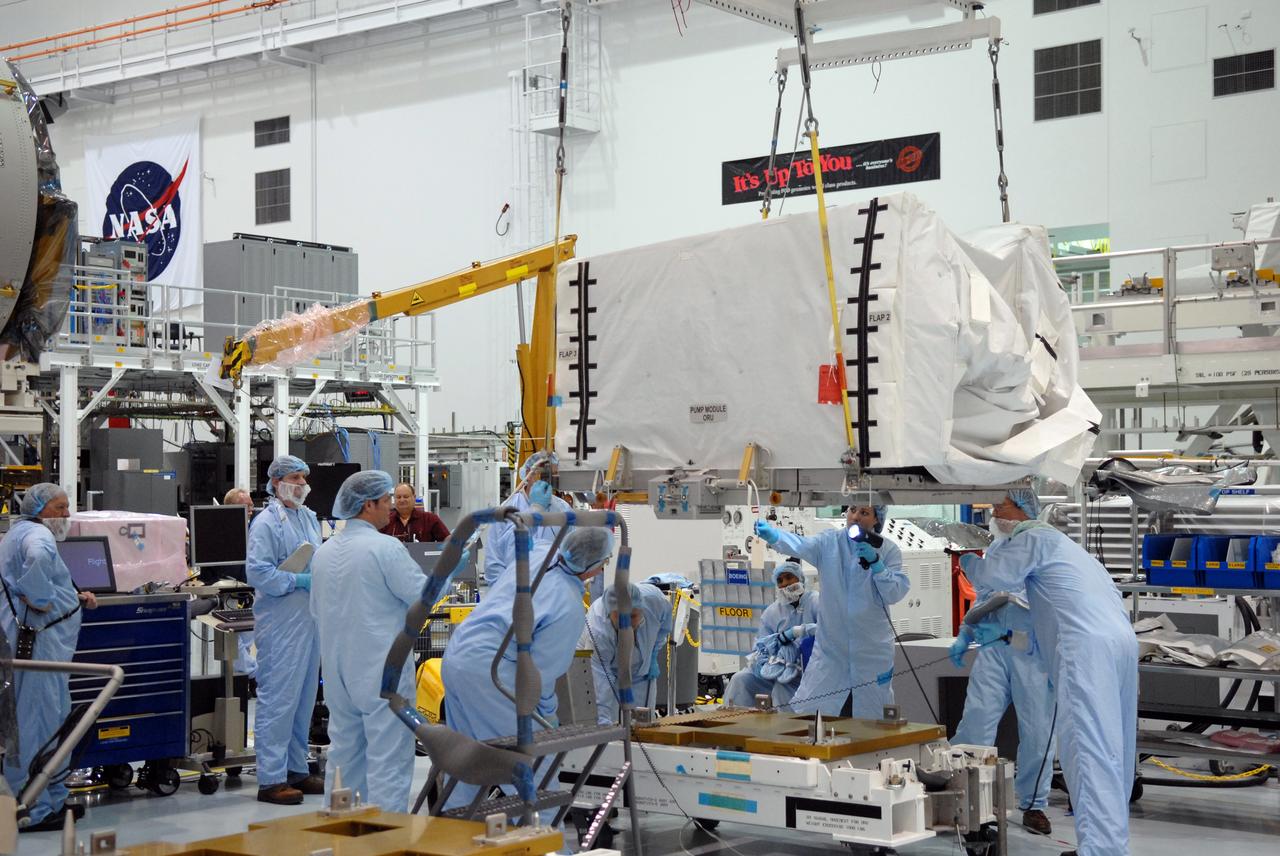
CAPE CANAVERAL, Fla. – In the space Station Processing Facility at NASA's Kennedy Space Center in Florida, technicians watch closely as the overhead crane lifts the pump module orbital replacement unit. The module will be moved to the Express Logistics Carrier 1, or ELC-1, for installation. The carrier is part of the STS-129 payload on space shuttle Atlantis, which will deliver to the International Space Station two spare gyroscopes, two nitrogen tank assemblies, two pump modules, an ammonia tank assembly and a spare latching end effector for the station's robotic arm. STS-129 is targeted to launch Nov. 12. Photo credit: NASA/Jim Grossmann

KENNEDY SPACE CENTER, FLA. -- Workers in the Vehicle Assembly Building watch as Space Shuttle Atlantis' Main Engine No. 1 is being removed. An inventory review concerning defective main engine fuel pump tip seals indicated that defective seals may be present on the fuel pump for the engine. The decision was made to replace the suspect engine with one originally slated for Discovery. The main engine nozzle, visible in the photo, is 7.8 feet across and 9.4 feet high. Space Shuttle Atlantis is scheduled to launch no earlier than April 17, 2000, on mission STS-101 to resupply the International Space Station for the arrival of the next pressurized module, the Russian-built Zvezda

CAPE CANAVERAL, Fla. – In the space Station Processing Facility at NASA's Kennedy Space Center in Florida, the pump module orbital replacement unit is moved to the Express Logistics Carrier 1, or ELC-1, for installation. The carrier is part of the STS-129 payload on space shuttle Atlantis, which will deliver to the International Space Station two spare gyroscopes, two nitrogen tank assemblies, two pump modules, an ammonia tank assembly and a spare latching end effector for the station's robotic arm. STS-129 is targeted to launch Nov. 12. Photo credit: NASA/Jim Grossmann
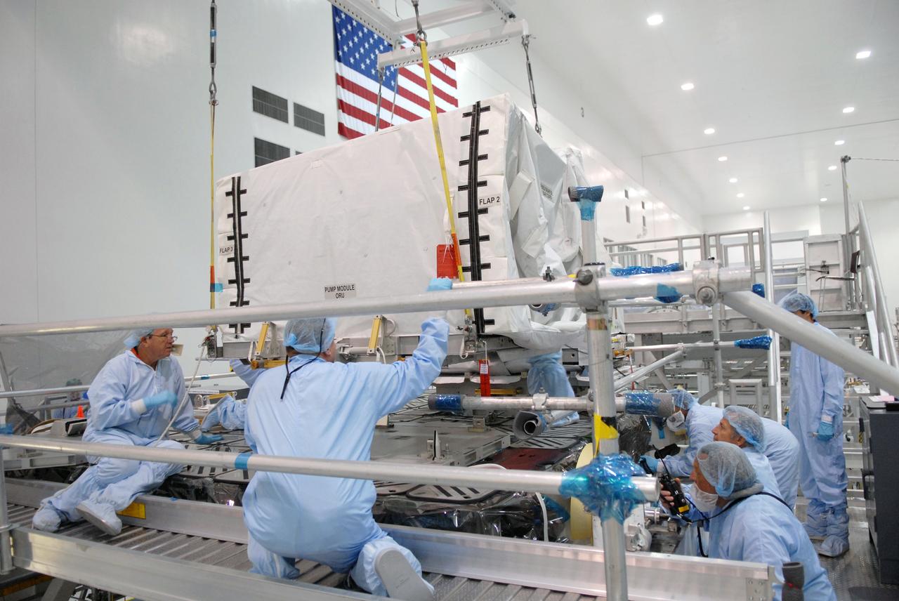
CAPE CANAVERAL, Fla. – In the space Station Processing Facility at NASA's Kennedy Space Center in Florida, technicians watch closely as the pump module orbital replacement unit is lowered onto the Express Logistics Carrier 1, or ELC-1, for installation. The carrier is part of the STS-129 payload on space shuttle Atlantis, which will deliver to the International Space Station two spare gyroscopes, two nitrogen tank assemblies, two pump modules, an ammonia tank assembly and a spare latching end effector for the station's robotic arm. STS-129 is targeted to launch Nov. 12. Photo credit: NASA/Jim Grossmann

CAPE CANAVERAL, Fla. - In the Space Station Processing Facility at NASA's Kennedy Space Center in Florida, technicians attach cables from an overhead crane to the pump module assembly plate for transfer to the Lightweight Multi-Purpose Experiment Support Structure Carrier, or LMC. The module assembly will be used to secure the return of a failed ammonia pump module in shuttle Atlantis' payload bay. Atlantis and its payload are being prepared for the STS-135 mission, which will deliver the Raffaello multipurpose logistics module packed with supplies, logistics and spare parts to the International Space Station. STS-135 is targeted to launch June 28, and will be the last spaceflight for the Space Shuttle Program. Photo credit: NASA/Jack Pfaller
CAPE CANAVERAL, Fla. - In the Space Station Processing Facility at NASA's Kennedy Space Center in Florida, technicians guide an overhead crane as it lifts the pump module assembly plate for transfer to the Lightweight Multi-Purpose Experiment Support Structure Carrier, or LMC. The module assembly will be used to secure the return of a failed ammonia pump module in shuttle Atlantis' payload bay. Atlantis and its payload are being prepared for the STS-135 mission, which will deliver the Raffaello multipurpose logistics module packed with supplies, logistics and spare parts to the International Space Station. STS-135 is targeted to launch June 28, and will be the last spaceflight for the Space Shuttle Program. Photo credit: NASA/Jack Pfaller

CAPE CANAVERAL, Fla. -- In the Space Station Processing Facility at NASA's Kennedy Space Center in Florida, technicians guide an overhead crane as it lifts the pump module assembly plate for transfer to the Lightweight Multi-Purpose Experiment Support Structure Carrier, or LMC. The module assembly will be used to secure the return of a failed ammonia pump module in shuttle Atlantis' payload bay. Atlantis and its payload are being prepared for the STS-135 mission, which will deliver the Raffaello multipurpose logistics module packed with supplies, logistics and spare parts to the International Space Station. STS-135 is targeted to launch June 28, and will be the last spaceflight for the Space Shuttle Program. Photo credit: NASA/Jack Pfaller

KENNEDY SPACE CENTER, FLA. -- In the Vehicle Assembly Building, Space Shuttle Atlantis' Main Engine No. 1 is lowered after its removal. An inventory review concerning defective main engine fuel pump tip seals indicated that defective seals may be present on the fuel pump for the engine. The decision was made to replace the suspect engine with one originally slated for Discovery. The main engine nozzle, visible in the photo, is 7.8 feet across and 9.4 feet high. Space Shuttle Atlantis is scheduled to launch no earlier than April 17, 2000, on mission STS-101 to resupply the International Space Station for the arrival of the next pressurized module, the Russian-built Zvezda
CAPE CANAVERAL, Fla. - In the Space Station Processing Facility at NASA's Kennedy Space Center in Florida, technicians guide an overhead crane as it lowers the pump module assembly plate toward the Lightweight Multi-Purpose Experiment Support Structure Carrier, or LMC. The module assembly will be used to secure the return of a failed ammonia pump module in shuttle Atlantis' payload bay. Atlantis and its payload are being prepared for the STS-135 mission, which will deliver the Raffaello multipurpose logistics module packed with supplies, logistics and spare parts to the International Space Station. STS-135 is targeted to launch June 28, and will be the last spaceflight for the Space Shuttle Program. Photo credit: NASA/Jack Pfaller
CAPE CANAVERAL, Fla. - In the Space Station Processing Facility at NASA's Kennedy Space Center in Florida, technicians secure the pump module assembly plate into position onto the Lightweight Multi-Purpose Experiment Support Structure Carrier, or LMC. The module assembly will be used to secure the return of a failed ammonia pump module in shuttle Atlantis' payload bay. Atlantis and its payload are being prepared for the STS-135 mission, which will deliver the Raffaello multipurpose logistics module packed with supplies, logistics and spare parts to the International Space Station. STS-135 is targeted to launch June 28, and will be the last spaceflight for the Space Shuttle Program. Photo credit: NASA/Jack Pfaller