L59 RC Kit Model/Learn to fly test technique and modeling development Persons in the picture: Left to right: Jay Brandon, Sue Grafton, Wes O'Neal, Mark Croom, Earl Harris, and Eric Viken
L59 RC Kit Model/Learn to fly test technique and modeling development Persons in the picture: Left to right: Jay Brandon, Sue Grafton, Wes O'Neal, Mark Croom, Earl Harris, and Eric Viken
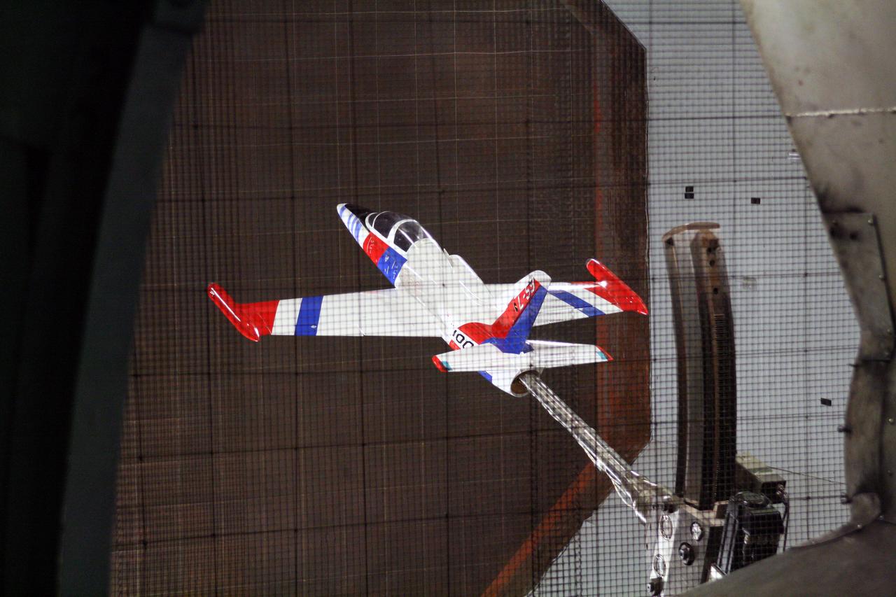
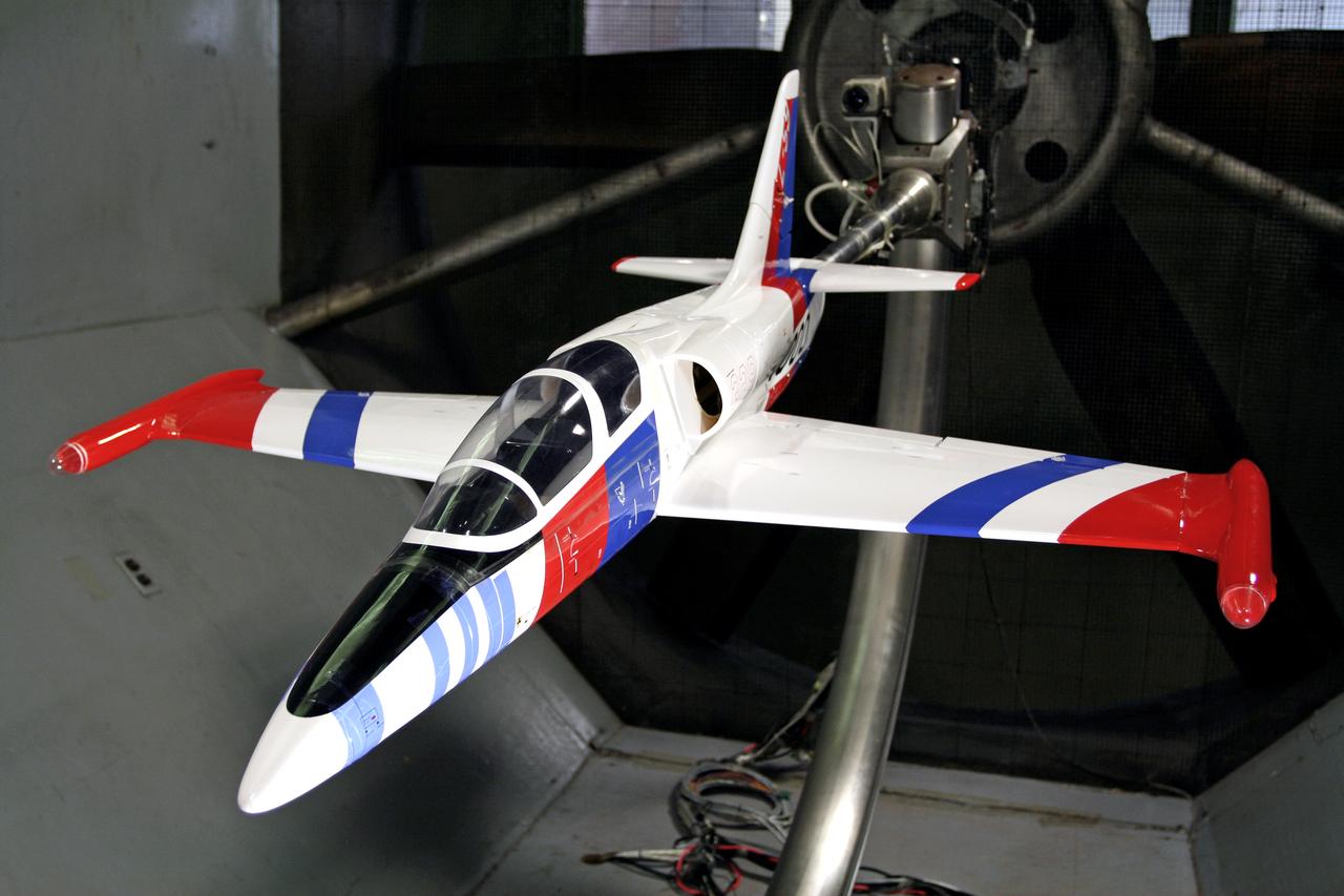
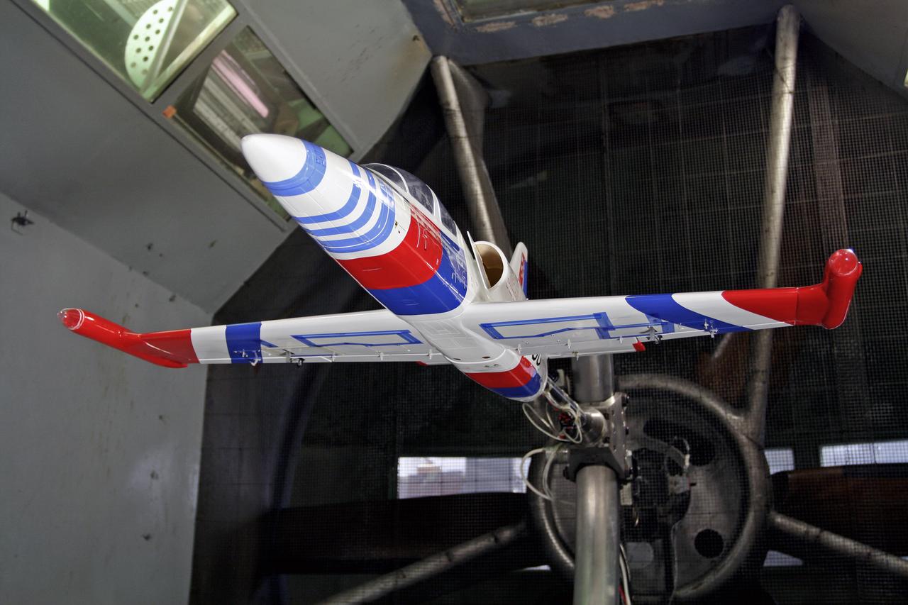
L59 RC Kit Model/Learn to fly test technique and modeling development Persons in the picture: Left to right: Jay Brandon, Sue Grafton, Wes O'Neal, Mark Croom, Earl Harris, and Eric Viken
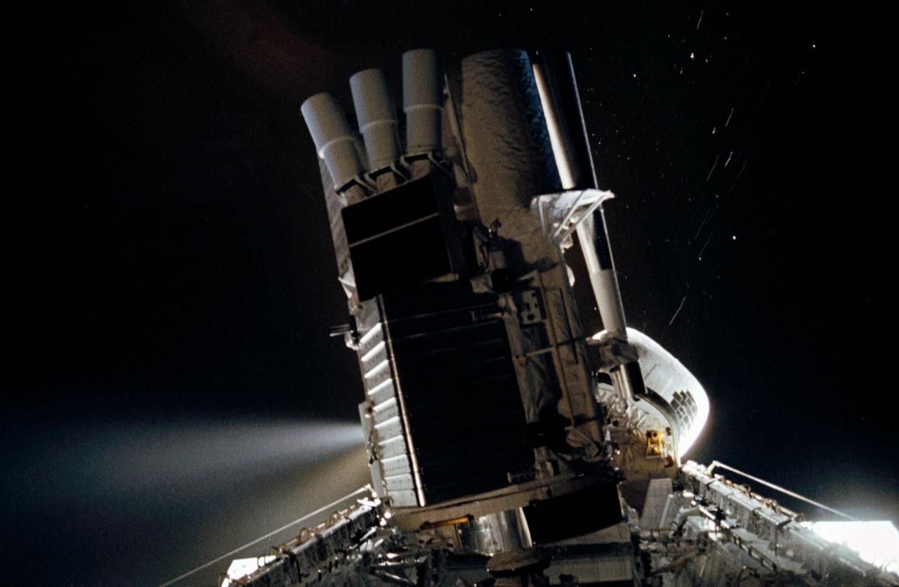
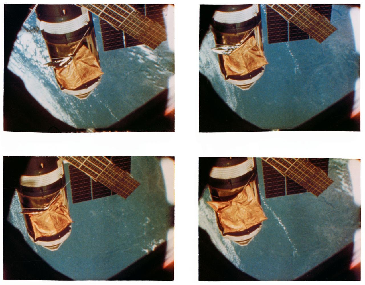
STS035-35-007 (2-10 Dec 1990) --- During the STS-35 mission, the Astronomy Laboratory 1 (ASTRO-1) payload, in its on-orbit operating configuration in the payload bay (PLB), is silhouetted against the firing of a reaction control system (RCS) jet. In the center of the frame, three ultraviolet telescopes are mounted and precisely co-aligned on a common structure, called the cruciform, that is attached to the instrument pointing system (IPS). Visible on the cruciform are Integrated Radiator System (IRS) (silver box on left), the Optical Sensor Package (OSP) (above IRS), the Ultraviolet Imaging Telescope (UIT), and the star tracker (S TRK) (far right). A right RCS jet is fired during this maneuver of Columbia, Orbiter Vehicle (OV) 102.
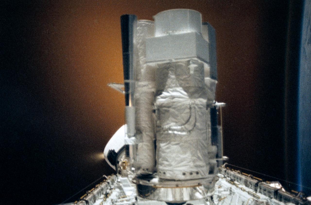
STS035-28-006 (2-10 Dec 1990) --- STS-35 Astronomy Laboratory 1 (ASTRO-1) telescopes, in on-orbit operating position in the payload bay (PLB), are silhouetted against an reaction control system (RCS) right thruster firing. Three ultraviolet telescopes are mounted and precisely co-aligned on a common structure, called the cruciform, that is attached to the instrument pointing system (IPS). Here the IPS holds the telescopes in a position that is parallel to the Earth's limb below. Visible on the cruciform are the star tracker (S TRK) (silver cone at the top), the Ultraviolet Imaging Telescope (UIT) (behind S TRK), and the Hopkins Ultraviolet Telescope(HUT).
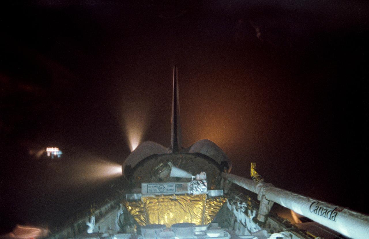
STS039-27-016 (28 April-6 May 1991) --- The Space Shuttle Discovery fires reaction control subsystem (RCS) thrusters in this 35mm frame, taken from inside the crew cabin. Seen in Discovery's payload bay are the tops of cannisters on the STP-1 payload, configured on the STS 39 Hitchhiker carrier; and the Air Force Program (AFP) 675 package. AFP-675 consists of the Cryogenic Infrared Radiance Instrumentation for Shuttle (CIRRIS)-1A; Far Ultraviolet Camera (FAR-UV) Experiment; Horizon Ultraviolet Program (HUP); Quadruple Ion Neutral Mass Spectrometer (QINMS); and the Uniformly Redundant Array (URA).
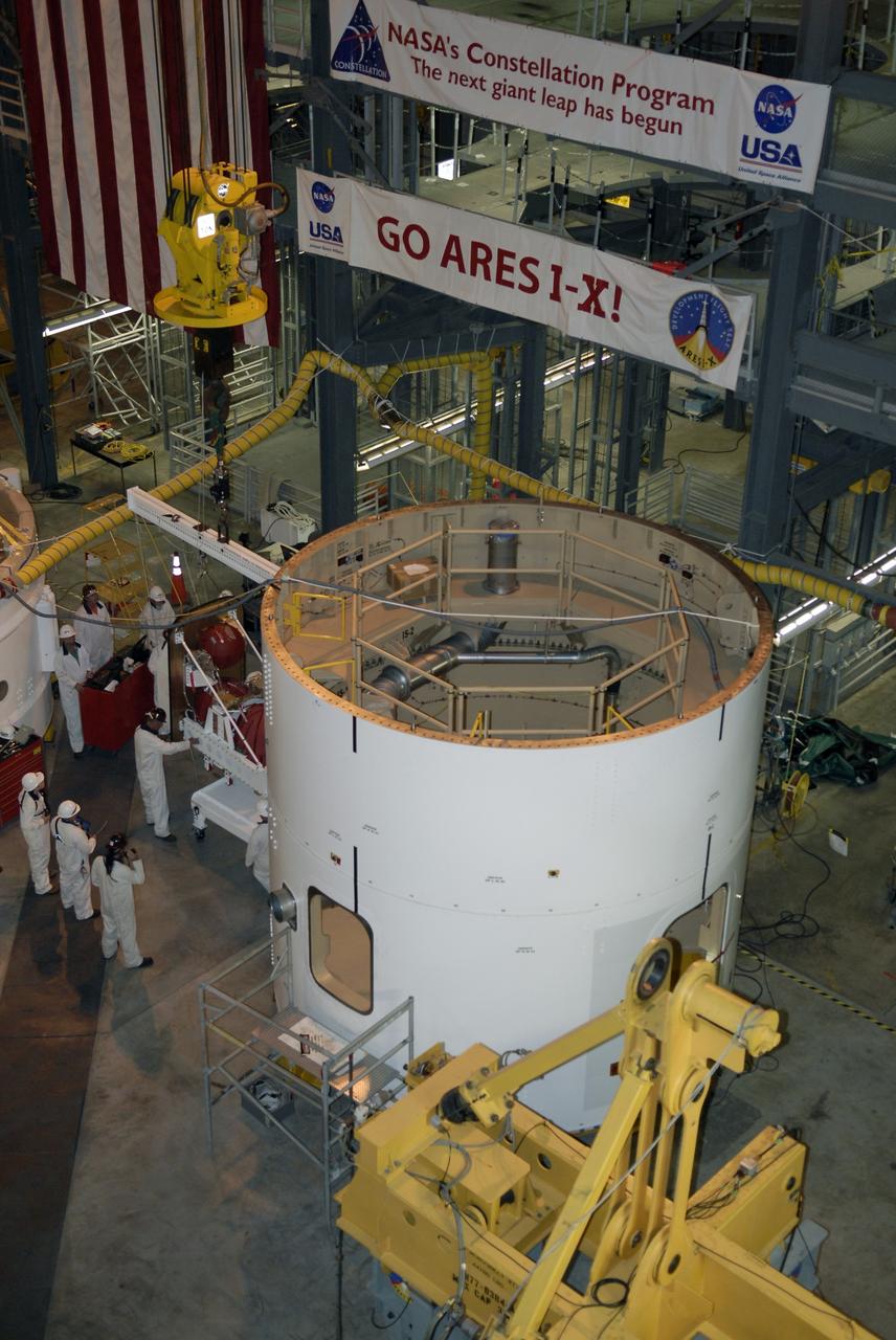
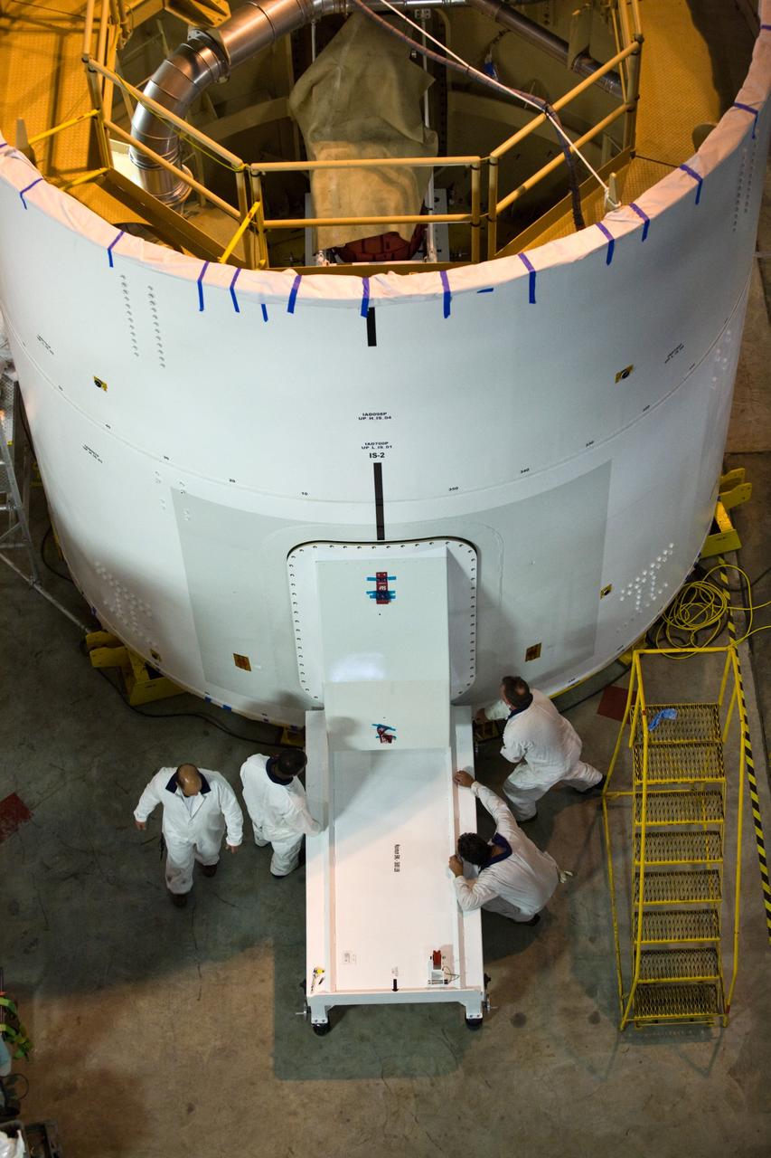
CAPE CANAVERAL, Fla. – In high bay 4 of the Vehicle Assembly Building at NASA's Kennedy Space Center in Florida, at left center, technicians get ready to install the roll control system in the Ares I-X segment in the center. Ares I-X is the test vehicle for the Ares I, which is part of the Constellation Program to return men to the moon and beyond. Ares I-X is targeted for launch in July 2009. Photo credit: NASA/Kim Shiflett
CAPE CANAVERAL, Fla. – In high bay 4 of the Vehicle Assembly Building at NASA's Kennedy Space Center in Florida, at right, technicians get ready to install the roll control system in the Ares I-X segment at left. Ares I-X is the test vehicle for the Ares I, which is part of the Constellation Program to return men to the moon and beyond. Ares I-X is targeted for launch in July 2009. Photo credit: NASA/Kim Shiflett
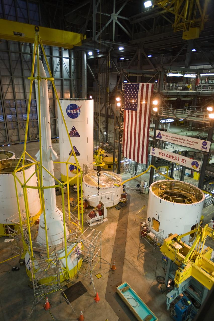
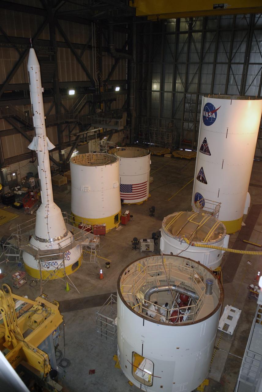
CAPE CANAVERAL, Fla. –– In High Bay 4 of the Vehicle Assembly Building at NASA's Kennedy Space Center in Florida, various segments of the Ares I-X are placed around the floor. In the center is a second roll control system module that will be installed in one of the segments. At left is the yellow metal framework, called the "birdcage," surrounding the simulator launch abort system and crew module. Ares I-X is the test vehicle for the Ares I, which is part of the Constellation Program to return men to the moon and beyond. Ares I-X is targeted for launch in August 2009. Photo credit: NASA/Dimitri Gerondidakis
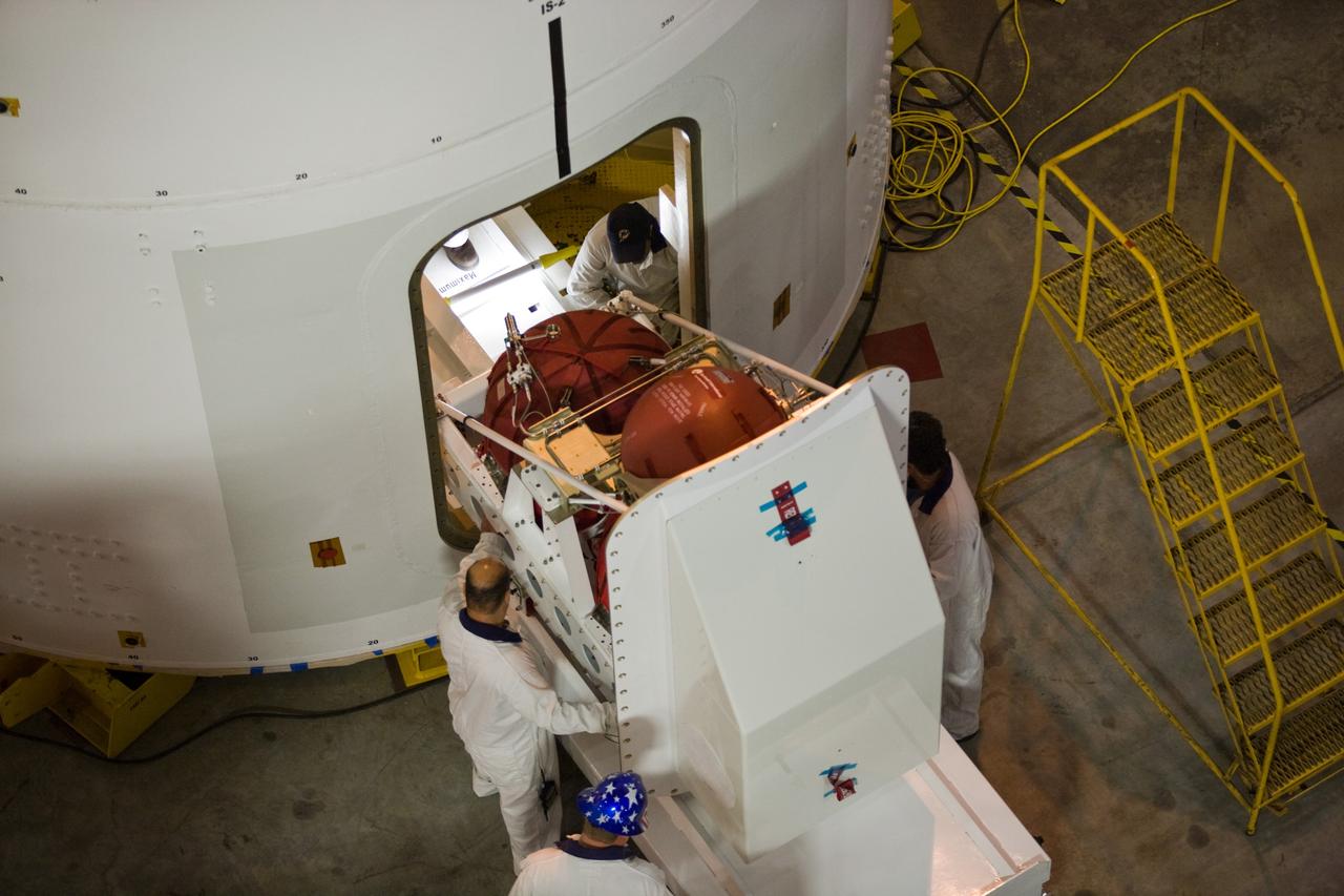
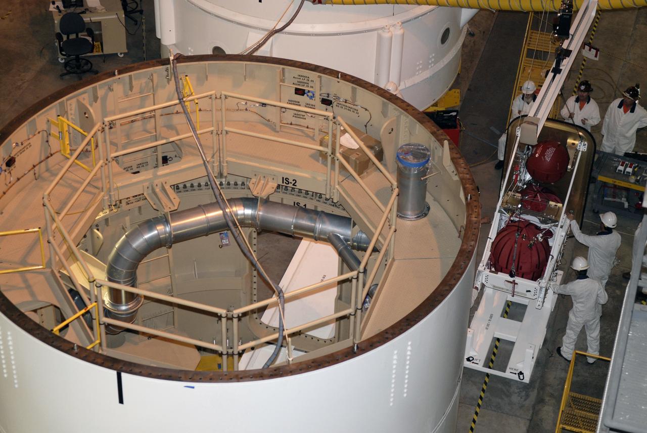
CAPE CANAVERAL, Fla. –– In High Bay 4 of the Vehicle Assembly Building at NASA's Kennedy Space Center in Florida, technicians maneuver a second roll control system module into place for installation in the Ares I-X segment. Ares I-X is the test vehicle for the Ares I, which is part of the Constellation Program to return men to the moon and beyond. Ares I-X is targeted for launch in August 2009. Photo credit: NASA/Dimitri Gerondidakis
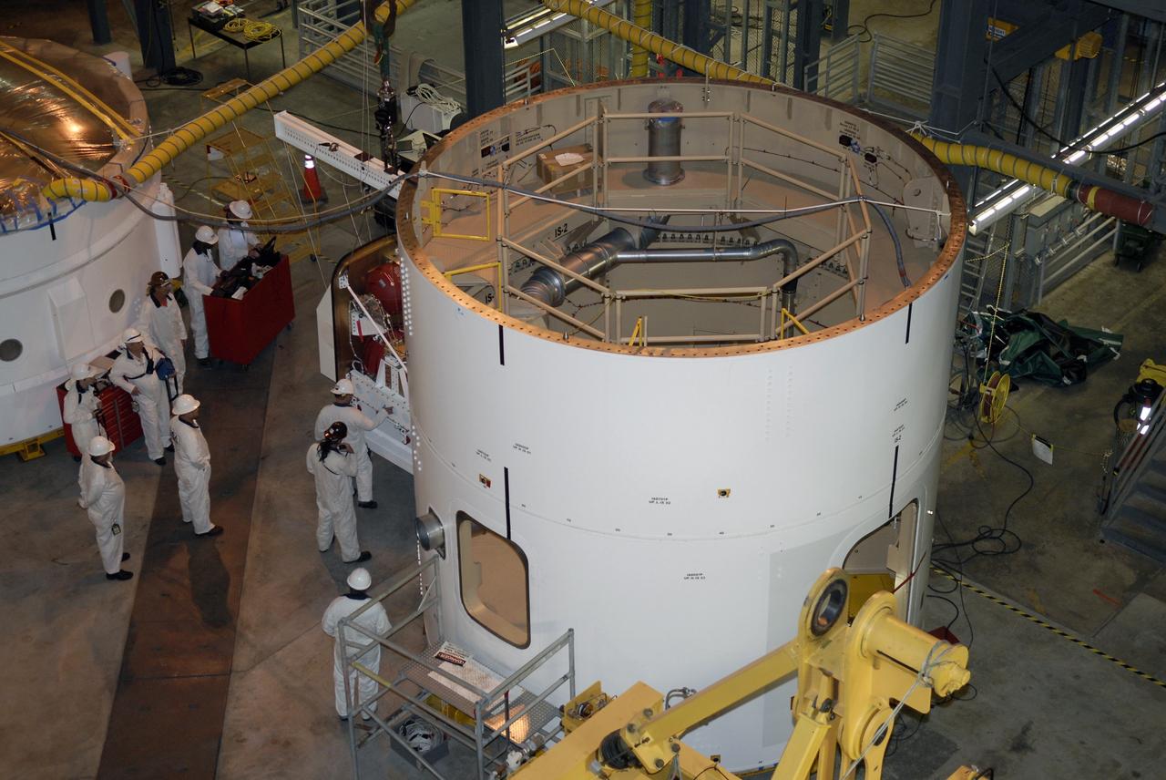
CAPE CANAVERAL, Fla. –– In high bay 4 of the Vehicle Assembly Building at NASA's Kennedy Space Center in Florida, at left center, technicians install the roll control system in the Ares I-X segment in the center. Ares I-X is the test vehicle for the Ares I, which is part of the Constellation Program to return men to the moon and beyond. Ares I-X is targeted for launch in July 2009. Photo credit: NASA/Kim Shiflett
CAPE CANAVERAL, Fla. –– In High Bay 4 of the Vehicle Assembly Building at NASA's Kennedy Space Center in Florida, a second roll control system module is ready to be installed in an Ares I-X segment. Ares I-X is the test vehicle for the Ares I, which is part of the Constellation Program to return men to the moon and beyond. Ares I-X is targeted for launch in August 2009. Photo credit: NASA/Dimitri Gerondidakis
CAPE CANAVERAL, Fla. –– In High Bay 4 of the Vehicle Assembly Building at NASA's Kennedy Space Center in Florida, technicians complete installation of a second roll control system module in an Ares I-X segment. Ares I-X is the test vehicle for the Ares I, which is part of the Constellation Program to return men to the moon and beyond. Ares I-X is targeted for launch in August 2009. Photo credit: NASA/Dimitri Gerondidakis
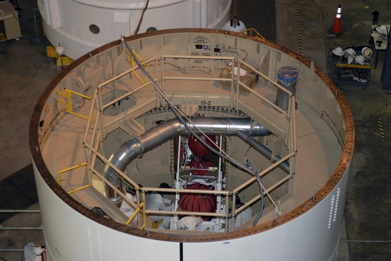
CAPE CANAVERAL, Fla. –– In high bay 4 of the Vehicle Assembly Building at NASA's Kennedy Space Center in Florida, technicians are seen inside the Ares I-X segment installing the roll control system. Ares I-X is the test vehicle for the Ares I, which is part of the Constellation Program to return men to the moon and beyond. Ares I-X is targeted for launch in July 2009. Photo credit: NASA/Kim Shiflett
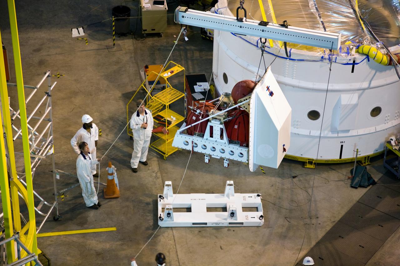
CAPE CANAVERAL, Fla. –– In High Bay 4 of the Vehicle Assembly Building at NASA's Kennedy Space Center in Florida, a crane lifts a second roll control system module for installation in an Ares I-X segment. Ares I-X is the test vehicle for the Ares I, which is part of the Constellation Program to return men to the moon and beyond. Ares I-X is targeted for launch in August 2009. Photo credit: NASA/Dimitri Gerondidakis

CAPE CANAVERAL, Fla. –– In High Bay 4 of the Vehicle Assembly Building at NASA's Kennedy Space Center in Florida, technicians are ready to maneuver a second roll control system module into place for installation in the Ares I-X segment. Ares I-X is the test vehicle for the Ares I, which is part of the Constellation Program to return men to the moon and beyond. Ares I-X is targeted for launch in August 2009. Photo credit: NASA/Dimitri Gerondidakis
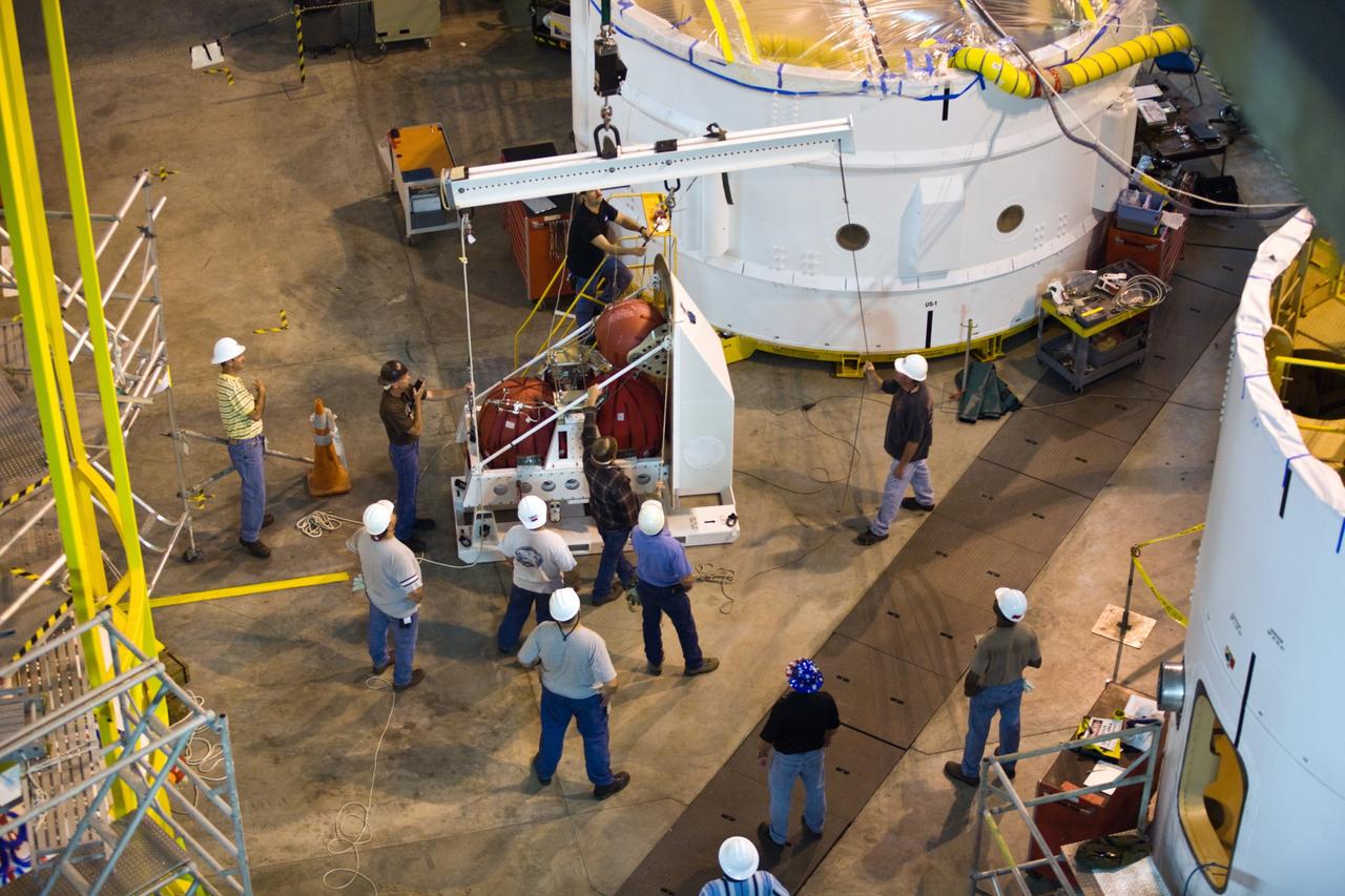
CAPE CANAVERAL, Fla. –– In High Bay 4 of the Vehicle Assembly Building at NASA's Kennedy Space Center in Florida, technicians maneuver the crane that will lift a second roll control system module for installation in an Ares I-X segment. Ares I-X is the test vehicle for the Ares I, which is part of the Constellation Program to return men to the moon and beyond. Ares I-X is targeted for launch in August 2009. Photo credit: NASA/Dimitri Gerondidakis
CAPE CANAVERAL, Fla. –– In the lower right, the roll control system can be seen installed inside the Ares I-X segment. The work is being done in high bay 4 of the Vehicle Assembly Building at NASA's Kennedy Space Center in Florida. Ares I-X is the test vehicle for the Ares I, which is part of the Constellation Program to return men to the moon and beyond. Ares I-X is targeted for launch in July 2009. Photo credit: NASA/Kim Shiflett
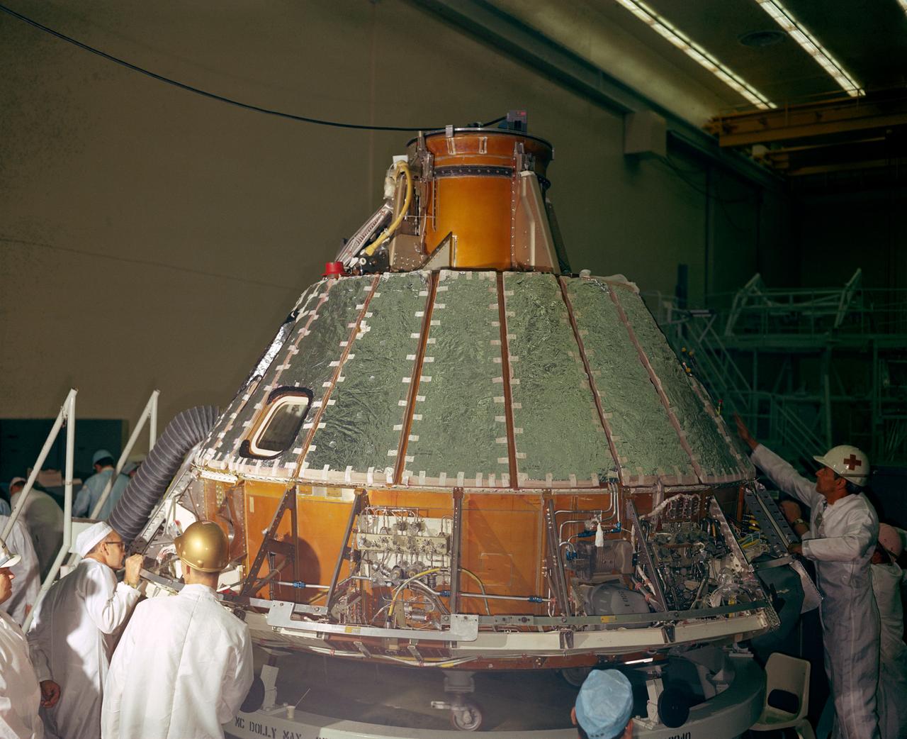
S66-41852 (1966) --- Spacecraft 012 looking toward -Y axis during installation of heat shield. Note uprighting system compressor in aft bay, at right, and Reaction Control System (RCS) valve module panel, center of photo.
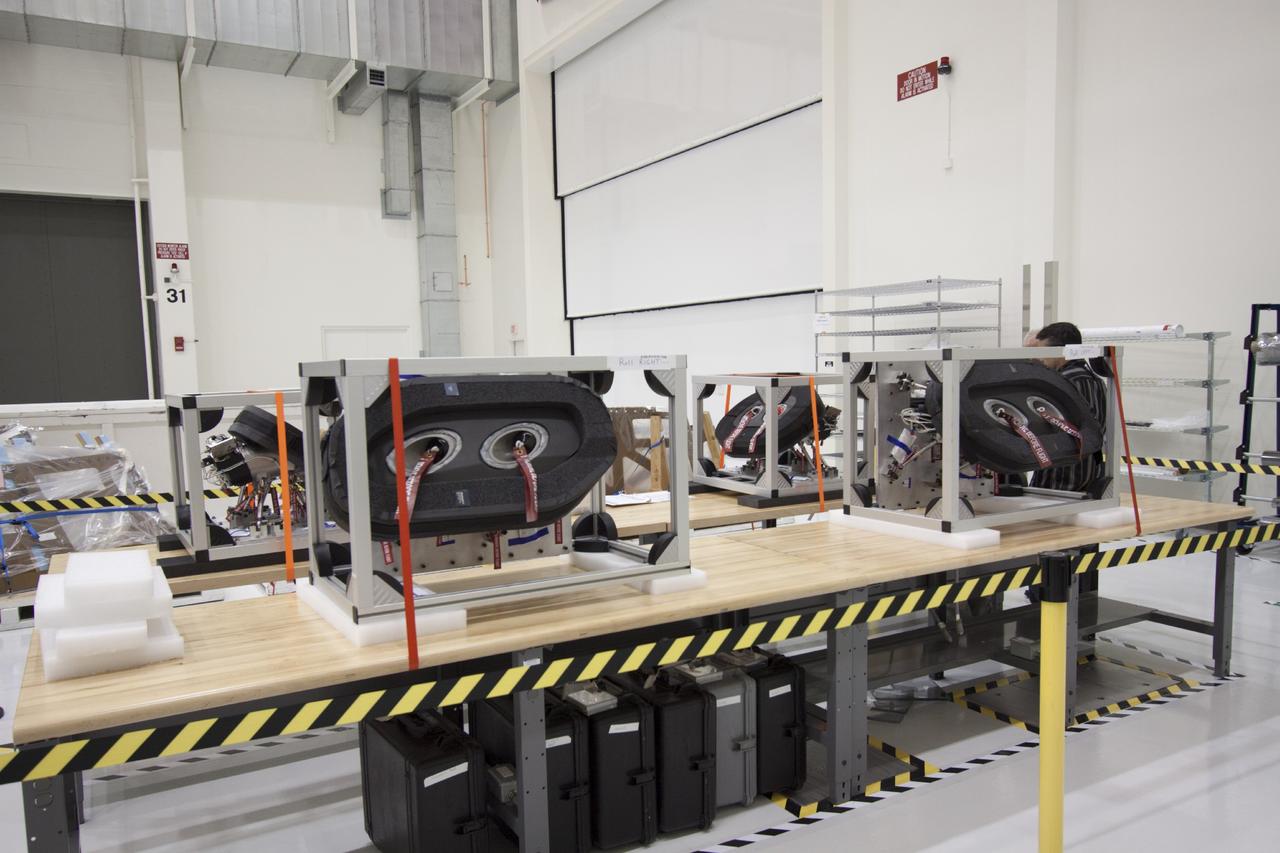
CAPE CANAVERAL, Fla. – Inside the Operations and Checkout Building high bay at NASA’s Kennedy Space Center in Florida, several of the reaction control system roll and yaw thrusters for the Orion crew module have been unpacked and placed on stands for processing. Orion is the exploration spacecraft designed to carry crews to space beyond low Earth orbit. It will provide emergency abort capability, sustain the crew during the space travel and provide safe re-entry from deep space return velocities. The first unpiloted test flight of the Orion is scheduled to launch in 2014 atop a Delta IV rocket and in 2017 on a Space Launch System rocket. For more information, visit http://www.nasa.gov/orion. Photo credit: NASA/Jim Grossmann
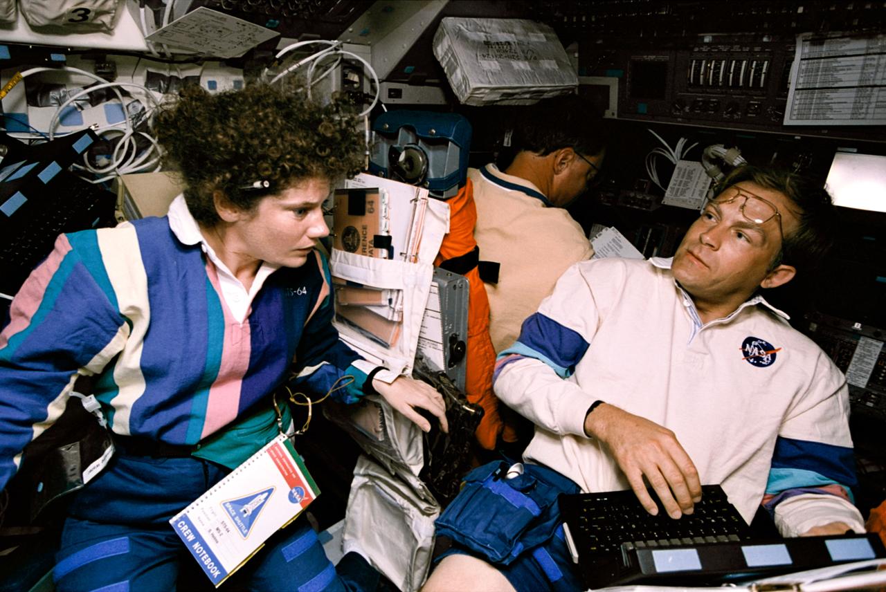
STS064-311-033 (10 Sept. 1994) --- Half of the crew members share support of the Shuttle Plume Impingement Flight Experiment (SPIFEX) in this 35mm frame. Astronauts Susan J. Helms and Mark C. Lee (foreground) share a pertinent bit of data while astronaut L. Blaine Hammond in the background controls Reaction Control System (RCS) thrusters on the space shuttle Discovery. Helms' role was to control the Remote Manipulator System (RMS) arm, to which 30-feet of SPIFEX hardware were appended in order to measure the RCS plume induced loads in the far field region. Lee records data on a lap top Payload General Support Computer (PGSC). SPIFEX was developed to help understand the thruster effects on approaching spacecraft. Photo credit: NASA or National Aeronautics and Space Administration
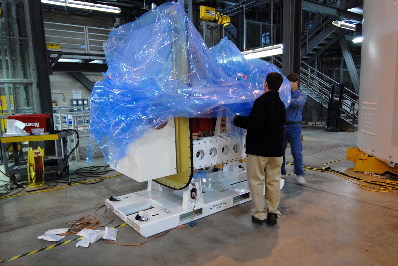
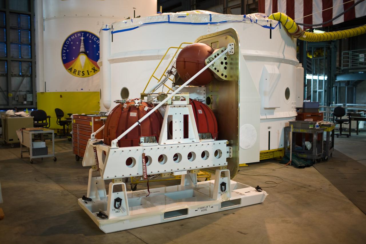
CAPE CANAVERAL, Fla. – On the floor of the Vehicle Assembly Building at NASA's Kennedy Space Center in Florida, workers start removing the plastic wrap from the Ares I-X roll control system module. The system is designed to perform a 90-degree roll after the rocket clears the launch tower, preventing a roll during flight and maintaining the orientation of the rocket until separation of the upper and first stages. Part of the upper stage simulator, the system module is composed to two modules and four thrusters. The system module will return to earth and splash down; it will not be recovered. Ares I-X is the test vehicle for the Ares I, which is part of the Constellation Program to return men to the moon and beyond. Ares I is the essential core of a safe, reliable, cost-effective space transportation system that eventually will carry crewed missions back to the moon, on to Mars and out into the solar system. Ares I-X is targeted for launch in July 2009. Photo credit: NASA/Jack Pfaller
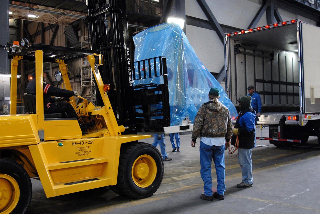
CAPE CANAVERAL, Fla. – The Ares I-X roll control system module arrives in the Vehicle Assembly Building at NASA's Kennedy Space Center in Florida. The system is designed to perform a 90-degree roll after the rocket clears the launch tower, preventing a roll during flight and maintaining the orientation of the rocket until separation of the upper and first stages. Part of the upper stage simulator, the system module is composed to two modules and four thrusters. The system module will return to earth and splash down; it will not be recovered. Ares I-X is the test vehicle for the Ares I, which is part of the Constellation Program to return men to the moon and beyond. Ares I is the essential core of a safe, reliable, cost-effective space transportation system that eventually will carry crewed missions back to the moon, on to Mars and out into the solar system. Ares I-X is targeted for launch in July 2009. Photo credit: NASA/Jack Pfaller
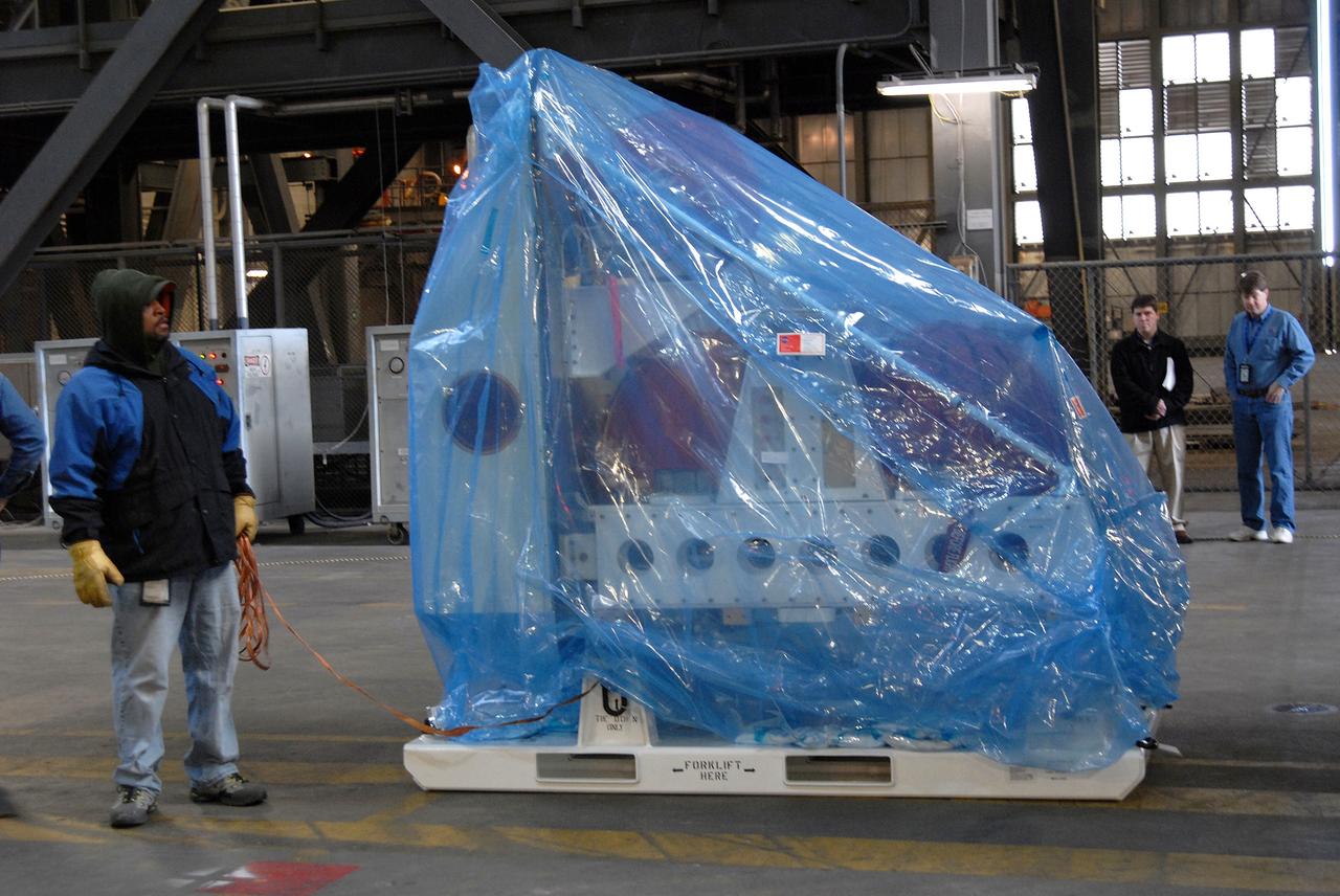
CAPE CANAVERAL, Fla. – The Ares I-X roll control system module has been placed on the floor of the Vehicle Assembly Building at NASA's Kennedy Space Center in Florida after its arrival. The system is designed to perform a 90-degree roll after the rocket clears the launch tower, preventing a roll during flight and maintaining the orientation of the rocket until separation of the upper and first stages. Part of the upper stage simulator, the system module is composed to two modules and four thrusters. The system module will return to earth and splash down; it will not be recovered. Ares I-X is the test vehicle for the Ares I, which is part of the Constellation Program to return men to the moon and beyond. Ares I is the essential core of a safe, reliable, cost-effective space transportation system that eventually will carry crewed missions back to the moon, on to Mars and out into the solar system. Ares I-X is targeted for launch in July 2009. Photo credit: NASA/Jack Pfaller
CAPE CANAVERAL, Fla. – In the Vehicle Assembly Building at NASA's Kennedy Space Center in Florida, workers look at the Ares I-X roll control system module before removing the plastic wrap. The system is designed to perform a 90-degree roll after the rocket clears the launch tower, preventing a roll during flight and maintaining the orientation of the rocket until separation of the upper and first stages. Part of the upper stage simulator, the system module is composed to two modules and four thrusters. The system module will return to earth and splash down; it will not be recovered. Ares I-X is the test vehicle for the Ares I, which is part of the Constellation Program to return men to the moon and beyond. Ares I is the essential core of a safe, reliable, cost-effective space transportation system that eventually will carry crewed missions back to the moon, on to Mars and out into the solar system. Ares I-X is targeted for launch in July 2009. Photo credit: NASA/Jack Pfaller
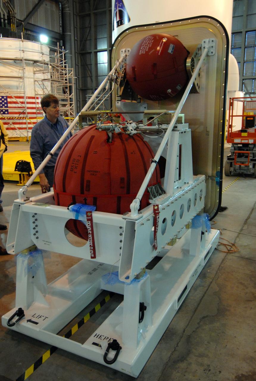
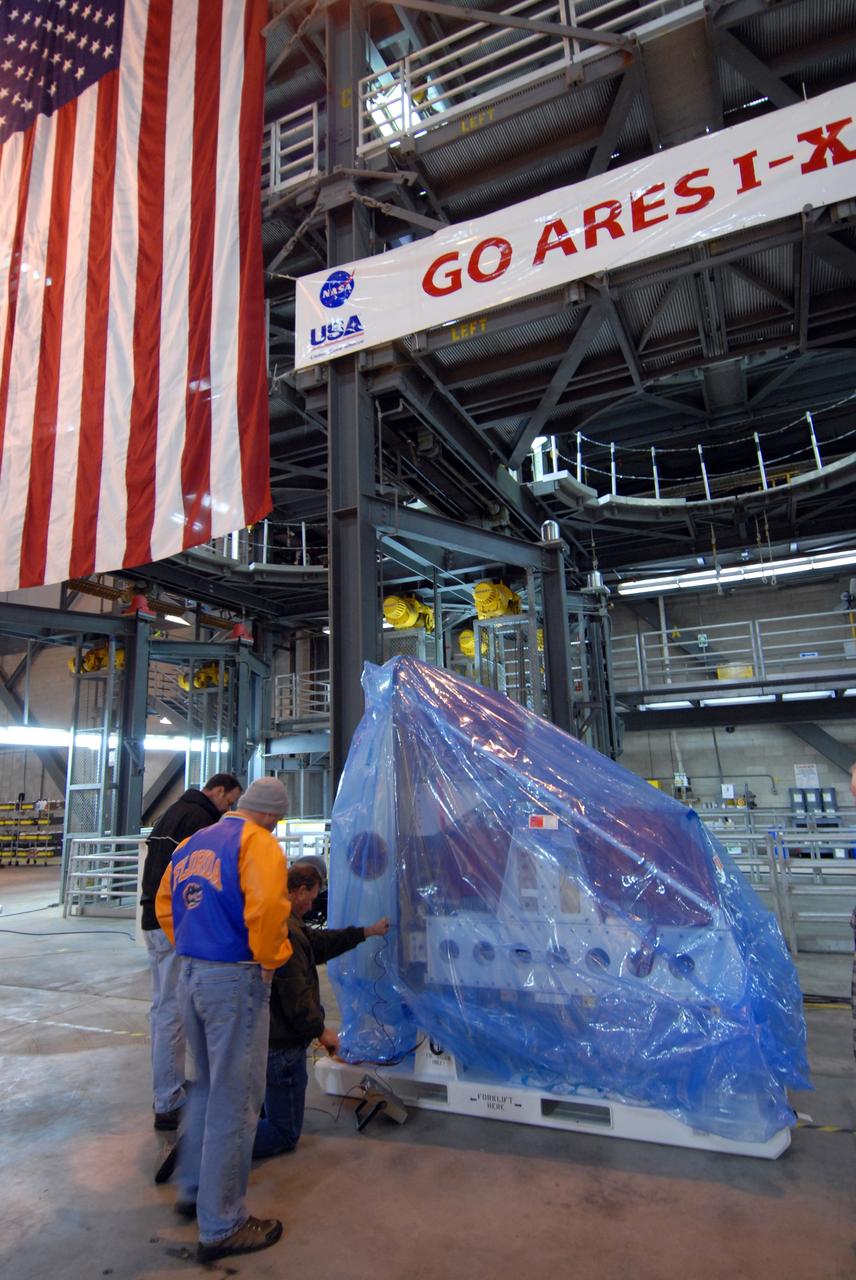
CAPE CANAVERAL, Fla. – The Ares I-X roll control system module is revealed after removal of the plastic wrap. The module is in the Vehicle Assembly Building at NASA's Kennedy Space Center in Florida. The system is designed to perform a 90-degree roll after the rocket clears the launch tower, preventing a roll during flight and maintaining the orientation of the rocket until separation of the upper and first stages. Part of the upper stage simulator, the system module is composed to two modules and four thrusters. The system module will return to earth and splash down; it will not be recovered. Ares I-X is the test vehicle for the Ares I, which is part of the Constellation Program to return men to the moon and beyond. Ares I is the essential core of a safe, reliable, cost-effective space transportation system that eventually will carry crewed missions back to the moon, on to Mars and out into the solar system. Ares I-X is targeted for launch in July 2009. Photo credit: NASA/Jack Pfaller
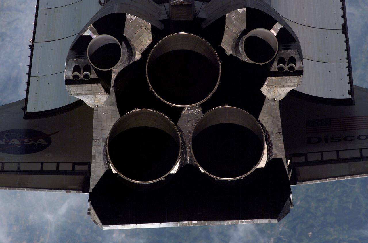
ISS013-E-47629 (6 July 2006) --- A close-up view of Space Shuttle Discovery's tail section is featured in this image photographed by an Expedition 13 crewmember on the International Space Station during STS-121 R-Pitch Maneuver survey on Flight Day 3. Visible are the shuttle's main engines, vertical stabilizer, orbital maneuvering system (OMS) pods, reaction control system (RCS) jets and a portion of payload bay door radiator and wings.
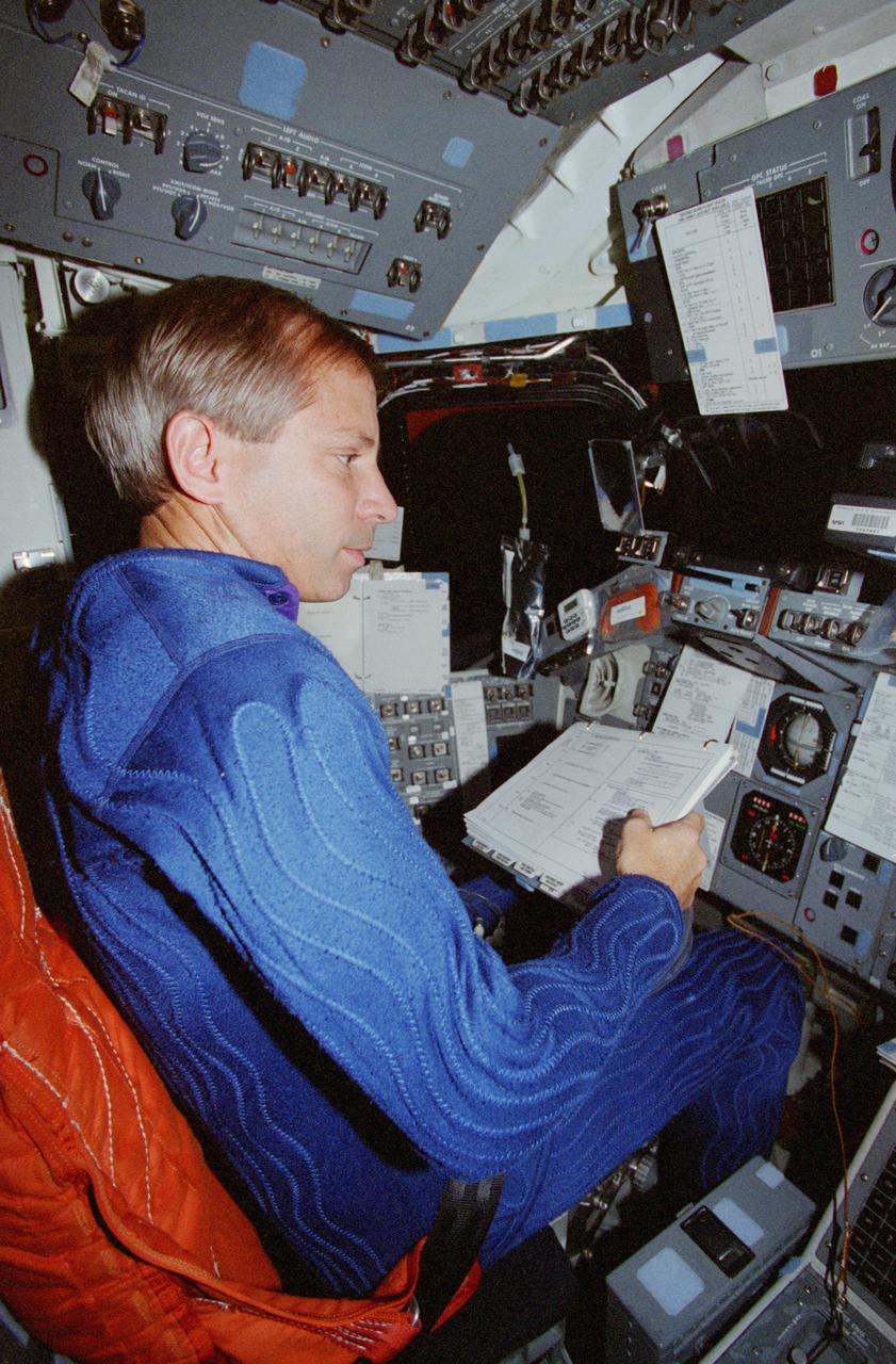
STS080-360-002 (19 Nov.-7 Dec. 1996) --- From the commander's station on the port side of the space shuttle Columbia's forward flight deck, astronaut Kenneth D. Cockrell prepares for a minor firing of Reaction Control System (RCS) engines during operations with the Wake Shield Facility (WSF). The activity was recorded with a 35mm camera on flight day seven. The commander is attired in a liquid-cooled biological garment.
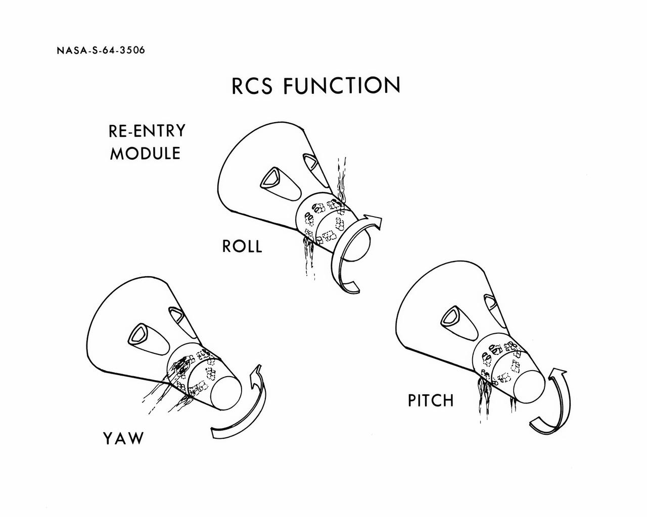
S64-03506 (1964) --- Diagrams shows Gemini spacecraft functions of the thrusters in the Gemini spacecraft's re-entry control system. Thrusters may be fired in various combinations to cause yaw, roll and pitch.
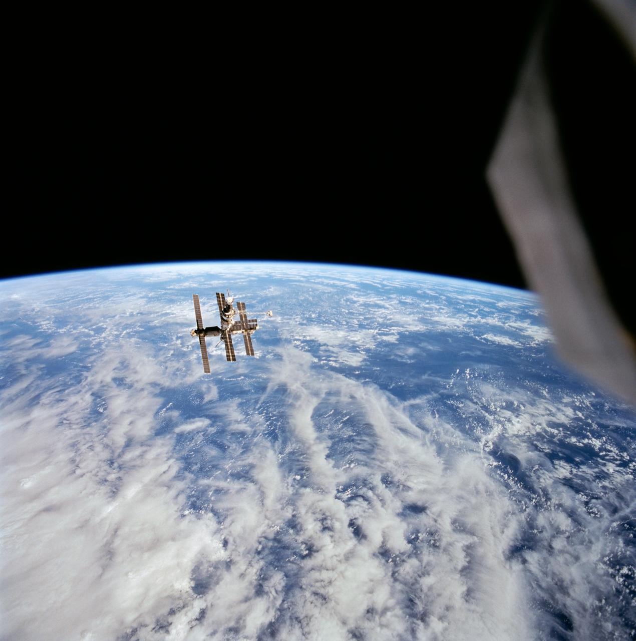
STS063-708-095 (6 Feb 1995) --- Cumulus and other clouds over the ocean form the backdrop for this scene of Russia's Mir space station during rendezvous operations by the Space Shuttle Discovery and Mir. This photograph was taken as the Discovery was firing its Reaction Control Subsystem (RCS) thrusters to separate from Mir's proximity. Onboard the Discovery were astronauts James D. Wetherbee, mission commander; Eileen M. Collins, pilot; Bernard A. Harris Jr., payload commander; mission specialists Janice Voss and C. Michael Foale; along with Russian cosmonaut Vladimir G. Titov. EDITOR'S NOTE: This 70mm handheld Hasselblad frame has been cropped to enlarge Mir.
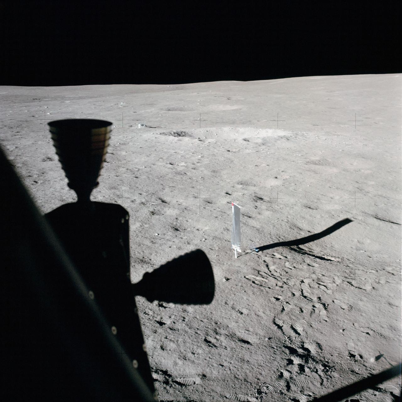
AS14-66-9322 (5-6 Feb. 1971) --- This photograph taken through a window of the Apollo 14 Lunar Module (LM), on the moon, shows an excellent view of the nearby terrain. In the center background is the deployed solar wind composition (SWC) experiment. Two LM RCS thrusters are silhouetted in the left foreground. While astronauts Alan B. Shepard Jr., commander; and Edgar D. Mitchell, lunar module pilot; descended in the LM, astronaut Stuart A. Roosa, command module pilot, remained with the Command and Service Modules (CSM) in lunar orbit.
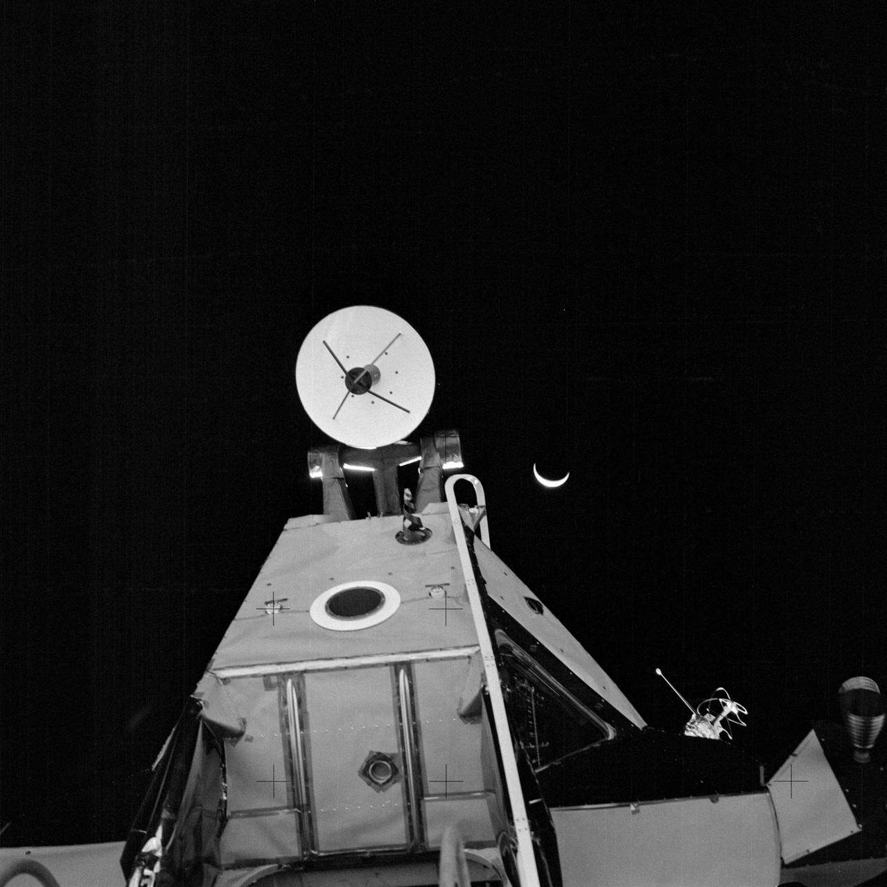
AS14-64-9193 (5 Feb. 1971) --- A close-up view of the forward section of the Apollo 14 Lunar Module (LM) ascent stage, looking upward from the LM ladder. This photograph was taken by one of the Apollo 14 astronauts at the close of their first extravehicular activity (EVA). The LM's ingress/egress hatch is just out of view at the bottom, near center. At the top center is the rendezvous radar antenna. An RCS thruster is visible at the far right. One of the two VHF antennas is on the right. The LM's optical alignment telescope is located at the black circle which has a wide, white ring around it. The crescent Earth can be seen in the far distant background.

ISS030-E-060117 (1 Feb. 2012) --- In the International Space Station?s Destiny laboratory, European Space Agency astronaut Andre Kuipers, Expedition 30 flight engineer, routes video cable for the High Rate Communication System (HRCS). HRCS will allow for two additional space-to-ground audio channels and two additional downlink video channels.
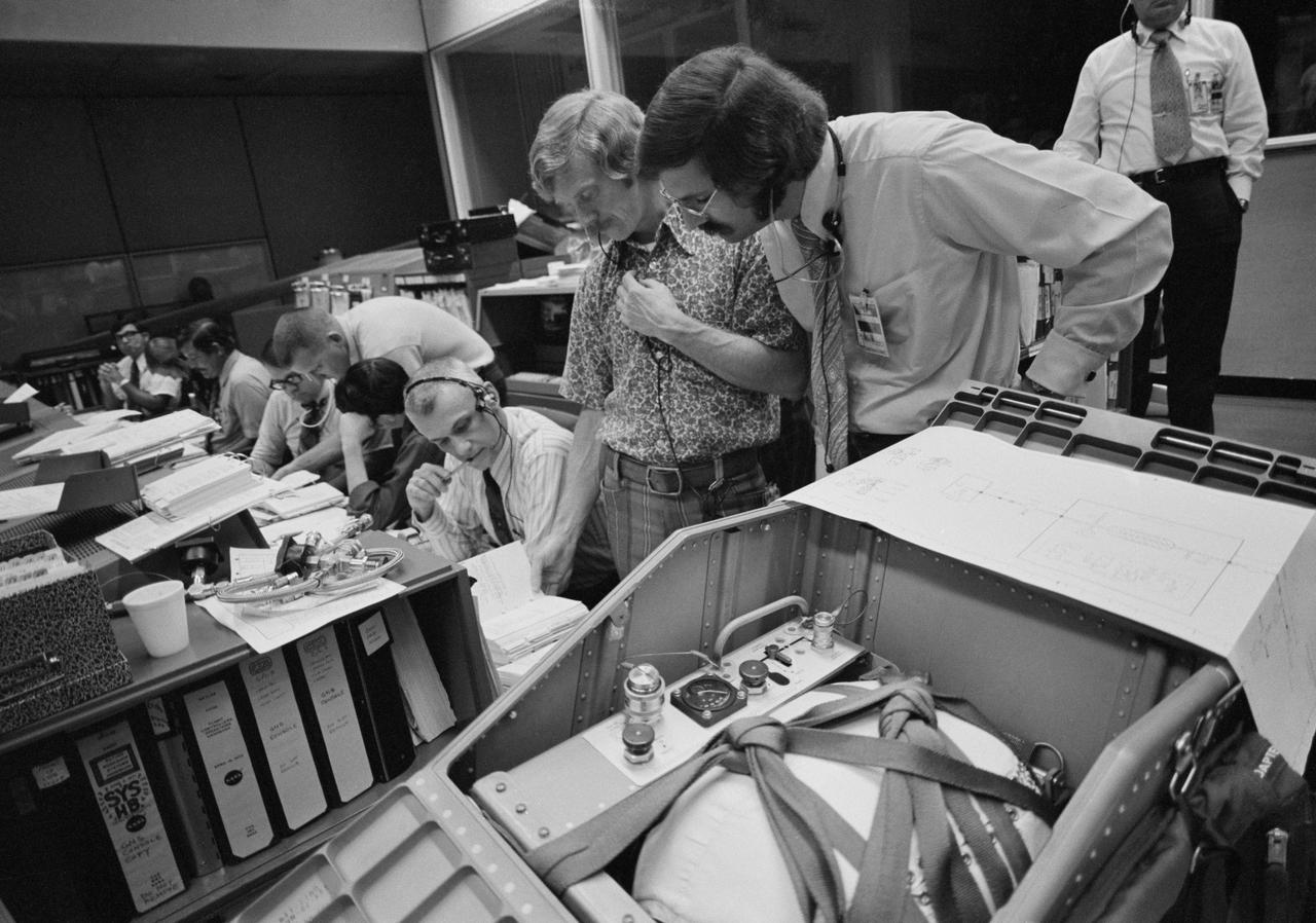
S73-37030 (November 1973) --- The procedures for repairing the coolant system aboard the Airlock Module of the Skylab space station in Earth orbit are discussed by flight controllers in the Mission Operations Control Room in the Mission Control Center at Johnson Space Center. Skylab 4 flight director Neil Hutchinson is on the right. Astronaut Russell L. Schweickart is wearing the sports shirt. Astronaut Bruce McCandless II, a Skylab 4 CAPCOM, is seated next to Schweickart. Items of equipment in the foreground are similar to components of a special coolant re-servicing kit which was taken to Earth orbit by the Skylab 4 crewmen. The kit consists of a tank containing 42 pounds of COOLANOL, a series of saddle valves, bolts and spacers, and leak-check hoses. The re-supply tank is a modified command module reaction control subsystem (RCS) fuel tank. Photo credit: NASA
S73-34619 (28 July 1973) --- A composite of four frames taken from 16mm movie camera footage showing an overhead view of the Skylab space station cluster in Earth orbit. The Maurer motion picture camera scenes were being filmed during the Skylab 3 Command/Service Module's (CSM) first "fly around" inspection of the space station. Close comparison of the four frames reveals movement of the improvised parasol solar shield over the Orbital Workshop (OWS). The "flapping" of the sun shade was caused from the exhaust of the reaction control subsystem (RCS) thrusters of the Skylab 3 CSM. The one remaining solar array system wing on the OWS is in the lower left background. The solar panel in the lower left foreground is on the Apollo Telescope Mount (ATM). Photo credit: NASA
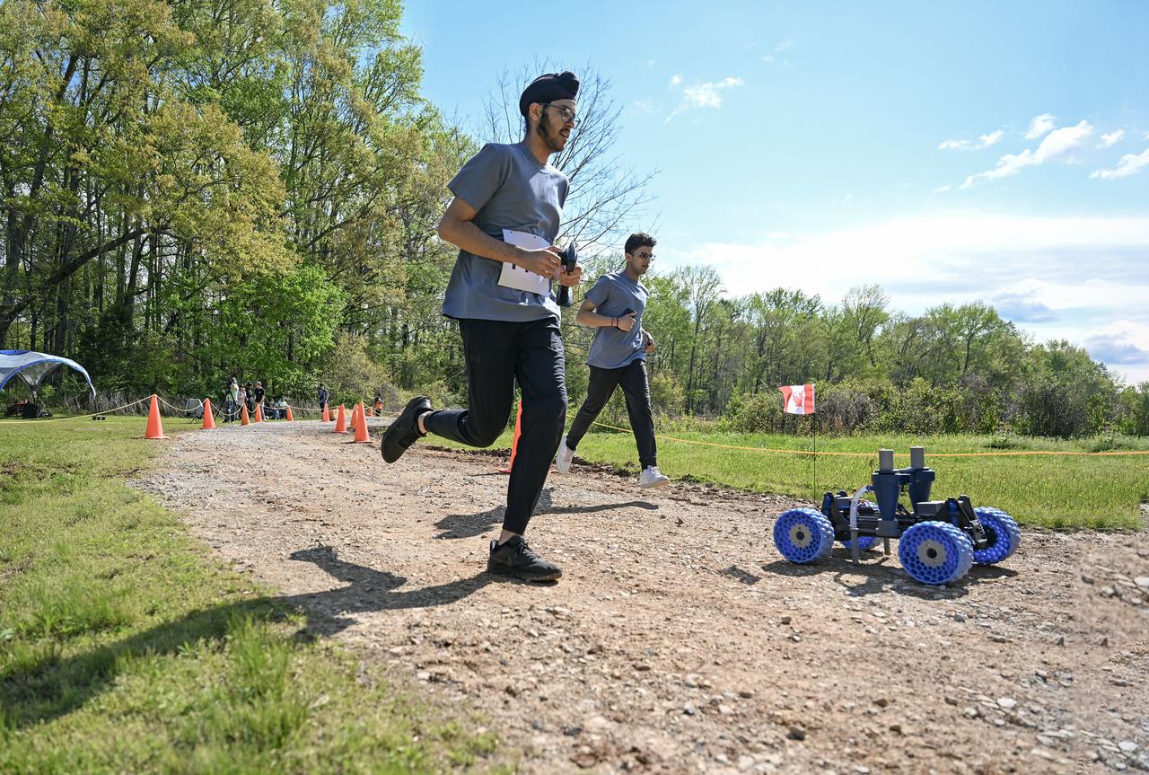
More than 500 students with 75 teams from around the world participated in the 31st year of NASA’s Human Exploration Rover Challenge (HERC) on April 11 and April 12, 2025, near NASA’s Marshall Space Flight Center in Huntsville, Alabama. Participating teams represented 35 colleges and universities, 38 high schools, and two middle schools from 20 states, Puerto Rico, and 16 other nations. NASA expanded the 2025 challenge to include a remote-control division - named Remote-Operated Vehicular Research - and invited middle school students to participate. Teams were awarded points based on navigating a half-mile obstacle course, conducting mission-specific task challenges, and completing multiple safety and design reviews with NASA engineers.