Bell X-1B fitted with a reaction control system on the lakebed
Bell X-1B fitted with a reaction control system on the lakebed.
Bell X-1B fitted with a reaction control system on the lakebed
The X-1B reaction control system thrusters are tested in 1958 and later proven on the X-15 as a way to control a vehicle in the absence of dynamic pressure.
NASA Armstrong Celebrates 70 Years of Flight Research
STS039-27-016 (28 April-6 May 1991) --- The Space Shuttle Discovery fires reaction control subsystem (RCS) thrusters in this 35mm frame, taken from inside the crew cabin.  Seen in Discovery's payload bay are the tops of cannisters on the STP-1 payload, configured on the STS 39 Hitchhiker carrier; and the Air Force Program (AFP) 675 package.  AFP-675 consists of the Cryogenic Infrared Radiance Instrumentation for Shuttle (CIRRIS)-1A; Far Ultraviolet Camera (FAR-UV) Experiment; Horizon Ultraviolet Program (HUP); Quadruple Ion Neutral Mass Spectrometer (QINMS); and the Uniformly Redundant Array (URA).
STS-39 OV-103 reaction control system (RCS) jets fire during onorbit maneuver
Behind three Douglas D-558-IIs is the B-29 launch aircraft. Under its right wing is the world’s first ground-based reaction control system motion simulator.
A Full Flightline at Armstrong
S64-03506 (1964) --- Diagrams shows Gemini spacecraft functions of the thrusters in the Gemini spacecraft's re-entry control system. Thrusters may be fired in various combinations to cause yaw, roll and pitch.
Diagrams of Spacecraft Reaction Control System (RCS) Function
Reaction Control System Thruster examined in the electron optics lab Near Field Emission Scanning Electron Microscope
GRC-2005-C-01164
KENNEDY SPACE CENTER, FLA. --  Inside NASA Kennedy Space Center’s Orbiter Processing Facility Bay 1, workers secure the overhead crane to the sling placed round the forward reaction control system that will be installed on Atlantis.  When ready, the shuttle equipment will be lifted for installation.   The forward reaction control system is located in the forward fuselage nose area.  During ascent of the space shuttle, it provides the thrust for attitude (rotational) maneuvers (pitch, yaw and roll) and for small velocity changes along the orbiter axis (translation maneuvers).
KSC-05pd2568
KENNEDY SPACE CENTER, FLA. --  Inside NASA Kennedy Space Center’s Orbiter Processing Facility Bay 1, workers move the sling into place around the forward reaction control system that will be installed on Atlantis.  When ready, the shuttle equipment will be lifted for installation. The forward reaction control system is located in the forward fuselage nose area.  During ascent of the space shuttle, it provides the thrust for attitude (rotational) maneuvers (pitch, yaw and roll) and for small velocity changes along the orbiter axis (translation maneuvers).
KSC-05pd2566
KENNEDY SPACE CENTER, FLA. --  Inside NASA Kennedy Space Center’s Orbiter Processing Facility Bay 1, workers make adjustments to the sling being placed round the forward reaction control system that will be installed on Atlantis. When ready, the shuttle equipment will be lifted for installation.  The forward reaction control system is located in the forward fuselage nose area.  During ascent of the space shuttle, it provides the thrust for attitude (rotational) maneuvers (pitch, yaw and roll) and for small velocity changes along the orbiter axis (translation maneuvers).
KSC-05pd2567
KENNEDY SPACE CENTER, FLA. --  Inside NASA Kennedy Space Center’s Orbiter Processing Facility Bay 1, workers get ready to lift the sling placed round the forward reaction control system that will be installed on Atlantis.  The forward reaction control system is located in the forward fuselage nose area.  During ascent of the space shuttle, it provides the thrust for attitude (rotational) maneuvers (pitch, yaw and roll) and for small velocity changes along the orbiter axis (translation maneuvers).
KSC-05pd2569
NASA Associate Administrator for Space Flight Joseph Rothenberg addresses attendees at a ribbon cutting for the new Checkout and Launch Control System (CLCS) at the Hypergolic Maintenance Facility (HMF). The CLCS was declared operational in a ribbon cutting ceremony earlier. The new control room will be used to process the Orbital Maneuvering System pods and Forward Reaction Control System modules at the HMF. This hardware is removed from Space Shuttle orbiters and routinely taken to the HMF for checkout and servicing
KSC-00pp1243
KSC Director Roy Bridges addresses attendees at a ribbon cutting for the new Checkout and Launch Control System (CLCS) at the Hypergolic Maintenance Facility (HMF). The CLCS was declared operational in a ribbon cutting ceremony earlier. The new control room will be used to process the Orbital Maneuvering System pods and Forward Reaction Control System modules at the HMF. This hardware is removed from Space Shuttle orbiters and routinely taken to the HMF for checkout and servicing
KSC00pp1242
KSC Director Roy Bridges addresses attendees at a ribbon cutting for the new Checkout and Launch Control System (CLCS) at the Hypergolic Maintenance Facility (HMF). The CLCS was declared operational in a ribbon cutting ceremony earlier. The new control room will be used to process the Orbital Maneuvering System pods and Forward Reaction Control System modules at the HMF. This hardware is removed from Space Shuttle orbiters and routinely taken to the HMF for checkout and servicing
KSC-00pp1242
KENNEDY SPACE CENTER, FLA. - In the Orbiter Processing Facility, one of two orbital maneuvering system (OMS) pods is being moved for installation on Atlantis.  The OMS pods are attached to the upper aft fuselage left and right sides. Fabricated primarily of graphite epoxy composite and aluminum, each pod is 21.8 feet long and 11.37 feet wide at its aft end and 8.41 feet wide at its forward end, with a surface area of approximately 435 square feet. Each pod houses the Reaction Control System propulsion components used for inflight maneuvering and is attached to the aft fuselage with 11 bolts.
KENNEDY SPACE CENTER, FLA. - In the Orbiter Processing Facility, one of two orbital maneuvering system (OMS) pods is being moved for installation on Atlantis. The OMS pods are attached to the upper aft fuselage left and right sides. Fabricated primarily of graphite epoxy composite and aluminum, each pod is 21.8 feet long and 11.37 feet wide at its aft end and 8.41 feet wide at its forward end, with a surface area of approximately 435 square feet. Each pod houses the Reaction Control System propulsion components used for inflight maneuvering and is attached to the aft fuselage with 11 bolts.
KENNEDY SPACE CENTER, FLA. - In the Orbiter Processing Facility, technicians move an orbital maneuvering system (OMS) pod into the correct position on Atlantis. The OMS pod is one of two that are attached to the upper aft fuselage left and right sides. Fabricated primarily of graphite epoxy composite and aluminum, each pod is 21.8 feet long and 11.37 feet wide at its aft end and 8.41 feet wide at its forward end, with a surface area of approximately 435 square feet. Each pod houses the Reaction Control System propulsion components used for inflight maneuvering and is attached to the aft fuselage with 11 bolts.
KENNEDY SPACE CENTER, FLA. - In the Orbiter Processing Facility, an orbital maneuvering system (OMS) pod is moved into place on Atlantis.  It is one of two OMS pods attached to the upper aft fuselage left and right sides. Fabricated primarily of graphite epoxy composite and aluminum, each pod is 21.8 feet long and 11.37 feet wide at its aft end and 8.41 feet wide at its forward end, with a surface area of approximately 435 square feet. Each pod houses the Reaction Control System propulsion components used for inflight maneuvering and is attached to the aft fuselage with 11 bolts.
KENNEDY SPACE CENTER, FLA. - In the Orbiter Processing Facility, an orbital maneuvering system (OMS) pod is moved into place on Atlantis. It is one of two OMS pods attached to the upper aft fuselage left and right sides. Fabricated primarily of graphite epoxy composite and aluminum, each pod is 21.8 feet long and 11.37 feet wide at its aft end and 8.41 feet wide at its forward end, with a surface area of approximately 435 square feet. Each pod houses the Reaction Control System propulsion components used for inflight maneuvering and is attached to the aft fuselage with 11 bolts.
KENNEDY SPACE CENTER, FLA. - In the Orbiter Processing Facility, workers discuss the next step in moving the orbital maneuvering system (OMS) pod behind them.  The OMS pod will be installed on Atlantis.  Two OMS pods are attached to the upper aft fuselage left and right sides. Fabricated primarily of graphite epoxy composite and aluminum, each pod is 21.8 feet long and 11.37 feet wide at its aft end and 8.41 feet wide at its forward end, with a surface area of approximately 435 square feet. Each pod houses the Reaction Control System propulsion components used for inflight maneuvering and is attached to the aft fuselage with 11 bolts.
KENNEDY SPACE CENTER, FLA. - In the Orbiter Processing Facility, workers discuss the next step in moving the orbital maneuvering system (OMS) pod behind them. The OMS pod will be installed on Atlantis. Two OMS pods are attached to the upper aft fuselage left and right sides. Fabricated primarily of graphite epoxy composite and aluminum, each pod is 21.8 feet long and 11.37 feet wide at its aft end and 8.41 feet wide at its forward end, with a surface area of approximately 435 square feet. Each pod houses the Reaction Control System propulsion components used for inflight maneuvering and is attached to the aft fuselage with 11 bolts.
KENNEDY SPACE CENTER, FLA. -  In the Orbiter Processing Facility, one of two orbital maneuvering system (OMS) pods is lifted off its stand to move it toward Atlantis for installation. The OMS pods are attached to the upper aft fuselage left and right sides. Fabricated primarily of graphite epoxy composite and aluminum, each pod is 21.8 feet long and 11.37 feet wide at its aft end and 8.41 feet wide at its forward end, with a surface area of approximately 435 square feet. Each pod houses the Reaction Control System propulsion components used for inflight maneuvering and is attached to the aft fuselage with 11 bolts.
KENNEDY SPACE CENTER, FLA. - In the Orbiter Processing Facility, one of two orbital maneuvering system (OMS) pods is lifted off its stand to move it toward Atlantis for installation. The OMS pods are attached to the upper aft fuselage left and right sides. Fabricated primarily of graphite epoxy composite and aluminum, each pod is 21.8 feet long and 11.37 feet wide at its aft end and 8.41 feet wide at its forward end, with a surface area of approximately 435 square feet. Each pod houses the Reaction Control System propulsion components used for inflight maneuvering and is attached to the aft fuselage with 11 bolts.
KENNEDY SPACE CENTER, FLA. - In the Orbiter Processing Facility, technicians make final adjustments to the orbital maneuvering system (OMS) pod being installed on Atlantis.   The OMS pod is one of two that are attached to the upper aft fuselage left and right sides. Fabricated primarily of graphite epoxy composite and aluminum, each pod is 21.8 feet long and 11.37 feet wide at its aft end and 8.41 feet wide at its forward end, with a surface area of approximately 435 square feet. Each pod houses the Reaction Control System propulsion components used for inflight maneuvering and is attached to the aft fuselage with 11 bolts.
KENNEDY SPACE CENTER, FLA. - In the Orbiter Processing Facility, technicians make final adjustments to the orbital maneuvering system (OMS) pod being installed on Atlantis. The OMS pod is one of two that are attached to the upper aft fuselage left and right sides. Fabricated primarily of graphite epoxy composite and aluminum, each pod is 21.8 feet long and 11.37 feet wide at its aft end and 8.41 feet wide at its forward end, with a surface area of approximately 435 square feet. Each pod houses the Reaction Control System propulsion components used for inflight maneuvering and is attached to the aft fuselage with 11 bolts.
KENNEDY SPACE CENTER, FLA. - In the Orbiter Processing Facility, one of two orbital maneuvering system (OMS) pods is being moved for installation on Atlantis.  The OMS pods are attached to the upper aft fuselage left and right sides. Fabricated primarily of graphite epoxy composite and aluminum, each pod is 21.8 feet long and 11.37 feet wide at its aft end and 8.41 feet wide at its forward end, with a surface area of approximately 435 square feet. Each pod houses the Reaction Control System propulsion components used for inflight maneuvering and is attached to the aft fuselage with 11 bolts.
KENNEDY SPACE CENTER, FLA. - In the Orbiter Processing Facility, one of two orbital maneuvering system (OMS) pods is being moved for installation on Atlantis. The OMS pods are attached to the upper aft fuselage left and right sides. Fabricated primarily of graphite epoxy composite and aluminum, each pod is 21.8 feet long and 11.37 feet wide at its aft end and 8.41 feet wide at its forward end, with a surface area of approximately 435 square feet. Each pod houses the Reaction Control System propulsion components used for inflight maneuvering and is attached to the aft fuselage with 11 bolts.
KENNEDY SPACE CENTER, FLA. - In the Orbiter Processing Facility, technicians make adjustments to the orbital maneuvering system (OMS) pod being installed on Atlantis.   The OMS pod is one of two that are attached to the upper aft fuselage left and right sides. Fabricated primarily of graphite epoxy composite and aluminum, each pod is 21.8 feet long and 11.37 feet wide at its aft end and 8.41 feet wide at its forward end, with a surface area of approximately 435 square feet. Each pod houses the Reaction Control System propulsion components used for inflight maneuvering and is attached to the aft fuselage with 11 bolts.
KENNEDY SPACE CENTER, FLA. - In the Orbiter Processing Facility, technicians make adjustments to the orbital maneuvering system (OMS) pod being installed on Atlantis. The OMS pod is one of two that are attached to the upper aft fuselage left and right sides. Fabricated primarily of graphite epoxy composite and aluminum, each pod is 21.8 feet long and 11.37 feet wide at its aft end and 8.41 feet wide at its forward end, with a surface area of approximately 435 square feet. Each pod houses the Reaction Control System propulsion components used for inflight maneuvering and is attached to the aft fuselage with 11 bolts.
KENNEDY SPACE CENTER, FLA. -  In the Orbiter Processing Facility, an orbital maneuvering system (OMS) pod is moved closer to Atlantis for installation.  Two OMS pods are attached to the upper aft fuselage left and right sides. Fabricated primarily of graphite epoxy composite and aluminum, each pod is 21.8 feet long and 11.37 feet wide at its aft end and 8.41 feet wide at its forward end, with a surface area of approximately 435 square feet. Each pod houses the Reaction Control System propulsion components used for inflight maneuvering and is attached to the aft fuselage with 11 bolts.
KENNEDY SPACE CENTER, FLA. - In the Orbiter Processing Facility, an orbital maneuvering system (OMS) pod is moved closer to Atlantis for installation. Two OMS pods are attached to the upper aft fuselage left and right sides. Fabricated primarily of graphite epoxy composite and aluminum, each pod is 21.8 feet long and 11.37 feet wide at its aft end and 8.41 feet wide at its forward end, with a surface area of approximately 435 square feet. Each pod houses the Reaction Control System propulsion components used for inflight maneuvering and is attached to the aft fuselage with 11 bolts.
KENNEDY SPACE CENTER, FLA. -  In the Orbiter Processing Facility, an orbital maneuvering system (OMS) pod is suspended in air as it is moved toward Atlantis for installation.  Two OMS pods are attached to the upper aft fuselage left and right sides. Fabricated primarily of graphite epoxy composite and aluminum, each pod is 21.8 feet long and 11.37 feet wide at its aft end and 8.41 feet wide at its forward end, with a surface area of approximately 435 square feet. Each pod houses the Reaction Control System propulsion components used for inflight maneuvering and is attached to the aft fuselage with 11 bolts.
KENNEDY SPACE CENTER, FLA. - In the Orbiter Processing Facility, an orbital maneuvering system (OMS) pod is suspended in air as it is moved toward Atlantis for installation. Two OMS pods are attached to the upper aft fuselage left and right sides. Fabricated primarily of graphite epoxy composite and aluminum, each pod is 21.8 feet long and 11.37 feet wide at its aft end and 8.41 feet wide at its forward end, with a surface area of approximately 435 square feet. Each pod houses the Reaction Control System propulsion components used for inflight maneuvering and is attached to the aft fuselage with 11 bolts.
KENNEDY SPACE CENTER, FLA. -  In the Orbiter Processing Facility, technicians move an orbital maneuvering system (OMS) pod into the correct position on Atlantis. The OMS pod is one of two that are attached to the upper aft fuselage left and right sides. Fabricated primarily of graphite epoxy composite and aluminum, each pod is 21.8 feet long and 11.37 feet wide at its aft end and 8.41 feet wide at its forward end, with a surface area of approximately 435 square feet. Each pod houses the Reaction Control System propulsion components used for inflight maneuvering and is attached to the aft fuselage with 11 bolts.
KENNEDY SPACE CENTER, FLA. - In the Orbiter Processing Facility, technicians move an orbital maneuvering system (OMS) pod into the correct position on Atlantis. The OMS pod is one of two that are attached to the upper aft fuselage left and right sides. Fabricated primarily of graphite epoxy composite and aluminum, each pod is 21.8 feet long and 11.37 feet wide at its aft end and 8.41 feet wide at its forward end, with a surface area of approximately 435 square feet. Each pod houses the Reaction Control System propulsion components used for inflight maneuvering and is attached to the aft fuselage with 11 bolts.
KENNEDY SPACE CENTER, FLA. - In the Orbiter Processing Facility, an orbital maneuvering system (OMS) pod is moved into place on Atlantis.  It is one of two OMS pods attached to the upper aft fuselage left and right sides. Fabricated primarily of graphite epoxy composite and aluminum, each pod is 21.8 feet long and 11.37 feet wide at its aft end and 8.41 feet wide at its forward end, with a surface area of approximately 435 square feet. Each pod houses the Reaction Control System propulsion components used for inflight maneuvering and is attached to the aft fuselage with 11 bolts.
KENNEDY SPACE CENTER, FLA. - In the Orbiter Processing Facility, an orbital maneuvering system (OMS) pod is moved into place on Atlantis. It is one of two OMS pods attached to the upper aft fuselage left and right sides. Fabricated primarily of graphite epoxy composite and aluminum, each pod is 21.8 feet long and 11.37 feet wide at its aft end and 8.41 feet wide at its forward end, with a surface area of approximately 435 square feet. Each pod houses the Reaction Control System propulsion components used for inflight maneuvering and is attached to the aft fuselage with 11 bolts.
S66-41852 (1966) --- Spacecraft 012 looking toward -Y axis during installation of heat shield. Note uprighting system compressor in aft bay, at right, and Reaction Control System (RCS) valve module panel, center of photo.
COMPRESSOR - UPRIGHTING SYSTEM - APOLLO MANUFACTURING - SPACECRAFT (S/C)-102 COMMAND MODULE (CM) - NORTH AMERICAN AVIATION (NAA), CA
STS106-352-009 (8-20 September 2000) --- Astronaut Terrence W. Wilcutt, STS-106 mission commander, performs a firing of the reaction control system on the flight deck of the Space Shuttle Atlantis. Earth’s horizon is visible through the commander’s window.
Commander Wilcutt works at the commander's workstation during STS-106
KENNEDY SPACE CENTER, FLA. --   In NASA Kennedy Space Center’s Orbiter Processing Facility Bay 1, technicians check details for the installation of the forward reaction control system on Atlantis (behind them).  The control system fits just behind the nose cone and provides the thrust for attitude (rotational) maneuvers (pitch, yaw and roll) and for small velocity changes along the orbiter axis (translation maneuvers).  Processing of Atlantis is under way for mission STS-115, the 19th flight to the International Space Station.
KSC-05pd2572
KENNEDY SPACE CENTER, FLA. --   In NASA Kennedy Space Center’s Orbiter Processing Facility Bay 1, workers are installing the forward reaction control system on Atlantis.  The control system fits just behind the nose cone and provides the thrust for attitude (rotational) maneuvers (pitch, yaw and roll) and for small velocity changes along the orbiter axis (translation maneuvers).  Processing of Atlantis is under way for mission STS-115, the 19th flight to the International Space Station.
KSC-05pd2570
KENNEDY SPACE CENTER, FLA. --   In NASA Kennedy Space Center’s Orbiter Processing Facility Bay 1, installation of the forward reaction control system on Atlantis is complete.  The control system fits just behind the nose cone and provides the thrust for attitude (rotational) maneuvers (pitch, yaw and roll) and for small velocity changes along the orbiter axis (translation maneuvers).  Processing of Atlantis is under way for mission STS-115, the 19th flight to the International Space Station.
KSC-05pd2574
KENNEDY SPACE CENTER, FLA. --   In NASA Kennedy Space Center’s Orbiter Processing Facility Bay 1, workers are installing the forward reaction control system on Atlantis.   The control system fits just behind the nose cone and provides the thrust for attitude (rotational) maneuvers (pitch, yaw and roll) and for small velocity changes along the orbiter axis (translation maneuvers).  Processing of Atlantis is under way for mission STS-115, the 19th flight to the International Space Station.
KSC-05pd2571
KENNEDY SPACE CENTER, FLA. --   In NASA Kennedy Space Center’s Orbiter Processing Facility Bay 1, a technician inspects a point of installation of the forward reaction control system on Atlantis. The control system fits just behind the nose cone and provides the thrust for attitude (rotational) maneuvers (pitch, yaw and roll) and for small velocity changes along the orbiter axis (translation maneuvers).  Processing of Atlantis is under way for mission STS-115, the 19th flight to the International Space Station.
KSC-05pd2573
The ribbon is cut and the new Checkout and Launch Control System (CLCS) declared operational. Those taking part in the ceremony are (from left) Joseph Rothenberg, NASA Associate Administrator for Space Flight; Pam Gillespie, from Rep. Dave Weldon's office; Roy Bridges, Kennedy Space Center director; Dave King, director of Shuttle Processing; Retha Hart, deputy associate director, Spaceport Technology Management Office; and Ron Dittemore, manager, Space Shuttle Program. The new control room will be used to process the Orbital Maneuvering System pods and Forward Reaction Control System modules at the HMF. This hardware is removed from Space Shuttle orbiters and routinely taken to the HMF for checkout and servicing
KSC-00pp1244
KSC Director Roy Bridges (center) and guests view the new Checkout and Launch Control System (CLCS) at the Hypergolic Maintenance Facility (HMF). Looking on next to him (left) is NASA Associate Administrator for Space Flight Joseph Rothenberg and Pam Gillespie (far right), from Rep. Dave Weldon’s office. The CLCS was declared operational in a ribbon cutting ceremony earlier. The new control room will be used to process the Orbital Maneuvering System pods and Forward Reaction Control System modules at the HMF. This hardware is removed from Space Shuttle orbiters and routinely taken to the HMF for checkout and servicing
KSC-00pp1245
The ribbon is cut and the new Checkout and Launch Control System (CLCS) declared operational. Those taking part in the ceremony are (from left) Joseph Rothenberg, NASA Associate Administrator for Space Flight; Pam Gillespie, from Rep. Dave Weldon's office; Roy Bridges, Kennedy Space Center director; Dave King, director of Shuttle Processing; Retha Hart, deputy associate director, Spaceport Technology Management Office; and Ron Dittemore, manager, Space Shuttle Program. The new control room will be used to process the Orbital Maneuvering System pods and Forward Reaction Control System modules at the HMF. This hardware is removed from Space Shuttle orbiters and routinely taken to the HMF for checkout and servicing
KSC00pp1244
KSC Director Roy Bridges (center) and guests view the new Checkout and Launch Control System (CLCS) at the Hypergolic Maintenance Facility (HMF). Looking on next to him (left) is NASA Associate Administrator for Space Flight Joseph Rothenberg and Pam Gillespie (far right), from Rep. Dave Weldon’s office. The CLCS was declared operational in a ribbon cutting ceremony earlier. The new control room will be used to process the Orbital Maneuvering System pods and Forward Reaction Control System modules at the HMF. This hardware is removed from Space Shuttle orbiters and routinely taken to the HMF for checkout and servicing
KSC00pp1245
KENNEDY SPACE CENTER, FLA. -   Technicians in the Orbiter Processing Facility oversee removal of one of two orbital maneuvering system (OMS) pods from Endeavour.  The OMS pods are attached to the upper aft fuselage left and right sides.  Fabricated primarily of graphite epoxy composite and aluminum, each pod is 21.8 feet long and 11.37 feet wide at its aft end and 8.41 feet wide at its forward end, with a surface area of approximately 435 square feet.  Each pod houses the Reaction Control System propulsion components used for inflight maneuvering and is attached to the aft fuselage with 11 bolts.   OMS pods are removed during Orbiter Major Modifications. Once removed, the OMS pods undergo in-depth structural inspections, system checks and the thrusters are changed out.
KENNEDY SPACE CENTER, FLA. - Technicians in the Orbiter Processing Facility oversee removal of one of two orbital maneuvering system (OMS) pods from Endeavour. The OMS pods are attached to the upper aft fuselage left and right sides. Fabricated primarily of graphite epoxy composite and aluminum, each pod is 21.8 feet long and 11.37 feet wide at its aft end and 8.41 feet wide at its forward end, with a surface area of approximately 435 square feet. Each pod houses the Reaction Control System propulsion components used for inflight maneuvering and is attached to the aft fuselage with 11 bolts. OMS pods are removed during Orbiter Major Modifications. Once removed, the OMS pods undergo in-depth structural inspections, system checks and the thrusters are changed out.
KENNEDY SPACE CENTER, FLA. -  In the Orbiter Processing Facility, one of two orbital maneuvering system (OMS) pods removed from Endeavour is lowered toward a transporter.  The OMS pods are attached to the upper aft fuselage left and right sides.  Fabricated primarily of graphite epoxy composite and aluminum, each pod is 21.8 feet long and 11.37 feet wide at its aft end and 8.41 feet wide at its forward end, with a surface area of approximately 435 square feet.  Each pod houses the Reaction Control System propulsion components used for inflight maneuvering and is attached to the aft fuselage with 11 bolts.   OMS pods are removed during Orbiter Major Modifications. Once removed, the OMS pods undergo in-depth structural inspections, system checks and the thrusters are changed out.
KENNEDY SPACE CENTER, FLA. - In the Orbiter Processing Facility, one of two orbital maneuvering system (OMS) pods removed from Endeavour is lowered toward a transporter. The OMS pods are attached to the upper aft fuselage left and right sides. Fabricated primarily of graphite epoxy composite and aluminum, each pod is 21.8 feet long and 11.37 feet wide at its aft end and 8.41 feet wide at its forward end, with a surface area of approximately 435 square feet. Each pod houses the Reaction Control System propulsion components used for inflight maneuvering and is attached to the aft fuselage with 11 bolts. OMS pods are removed during Orbiter Major Modifications. Once removed, the OMS pods undergo in-depth structural inspections, system checks and the thrusters are changed out.
KENNEDY SPACE CENTER, FLA. -  In the Orbiter Processing Facility, one of two orbital maneuvering system (OMS) pods removed from Endeavour is lowered onto a transporter.  The OMS pods are attached to the upper aft fuselage left and right sides.  Fabricated primarily of graphite epoxy composite and aluminum, each pod is 21.8 feet long and 11.37 feet wide at its aft end and 8.41 feet wide at its forward end, with a surface area of approximately 435 square feet.  Each pod houses the Reaction Control System propulsion components used for inflight maneuvering and is attached to the aft fuselage with 11 bolts.   OMS pods are removed during Orbiter Major Modifications. Once removed, the OMS pods undergo in-depth structural inspections, system checks and the thrusters are changed out.
KENNEDY SPACE CENTER, FLA. - In the Orbiter Processing Facility, one of two orbital maneuvering system (OMS) pods removed from Endeavour is lowered onto a transporter. The OMS pods are attached to the upper aft fuselage left and right sides. Fabricated primarily of graphite epoxy composite and aluminum, each pod is 21.8 feet long and 11.37 feet wide at its aft end and 8.41 feet wide at its forward end, with a surface area of approximately 435 square feet. Each pod houses the Reaction Control System propulsion components used for inflight maneuvering and is attached to the aft fuselage with 11 bolts. OMS pods are removed during Orbiter Major Modifications. Once removed, the OMS pods undergo in-depth structural inspections, system checks and the thrusters are changed out.
KENNEDY SPACE CENTER, FLA. -  Workers in the Orbiter Processing Facility prepare to remove one of two orbital maneuvering system (OMS) pods from Endeavour.  The OMS pods are attached to the upper aft fuselage left and right sides.  Fabricated primarily of graphite epoxy composite and aluminum, each pod is 21.8 feet long and 11.37 feet wide at its aft end and 8.41 feet wide at its forward end, with a surface area of approximately 435 square feet. Each pod houses the Reaction Control System propulsion components used for inflight maneuvering and is attached to the aft fuselage with 11 bolts.   OMS pods are removed during Orbiter Major Modifications. Once removed, the OMS pods undergo in-depth structural inspections, system checks and the thrusters are changed out.
KENNEDY SPACE CENTER, FLA. - Workers in the Orbiter Processing Facility prepare to remove one of two orbital maneuvering system (OMS) pods from Endeavour. The OMS pods are attached to the upper aft fuselage left and right sides. Fabricated primarily of graphite epoxy composite and aluminum, each pod is 21.8 feet long and 11.37 feet wide at its aft end and 8.41 feet wide at its forward end, with a surface area of approximately 435 square feet. Each pod houses the Reaction Control System propulsion components used for inflight maneuvering and is attached to the aft fuselage with 11 bolts. OMS pods are removed during Orbiter Major Modifications. Once removed, the OMS pods undergo in-depth structural inspections, system checks and the thrusters are changed out.
KENNEDY SPACE CENTER, FLA. -   In the Orbiter Processing Facility, one of two orbital maneuvering system (OMS) pods removed from Endeavour is suspended overhead.  The OMS pods are attached to the upper aft fuselage left and right sides.  Fabricated primarily of graphite epoxy composite and aluminum, each pod is 21.8 feet long and 11.37 feet wide at its aft end and 8.41 feet wide at its forward end, with a surface area of approximately 435 square feet.  Each pod houses the Reaction Control System propulsion components used for inflight maneuvering and is attached to the aft fuselage with 11 bolts.   OMS pods are removed during Orbiter Major Modifications. Once removed, the OMS pods undergo in-depth structural inspections, system checks and the thrusters are changed out.
KENNEDY SPACE CENTER, FLA. - In the Orbiter Processing Facility, one of two orbital maneuvering system (OMS) pods removed from Endeavour is suspended overhead. The OMS pods are attached to the upper aft fuselage left and right sides. Fabricated primarily of graphite epoxy composite and aluminum, each pod is 21.8 feet long and 11.37 feet wide at its aft end and 8.41 feet wide at its forward end, with a surface area of approximately 435 square feet. Each pod houses the Reaction Control System propulsion components used for inflight maneuvering and is attached to the aft fuselage with 11 bolts. OMS pods are removed during Orbiter Major Modifications. Once removed, the OMS pods undergo in-depth structural inspections, system checks and the thrusters are changed out.
KENNEDY SPACE CENTER, FLA. -  Workers in the Orbiter Processing Facility prepare to remove one of two orbital maneuvering system (OMS) pods from Endeavour.  The OMS pods are attached to the upper aft fuselage left and right sides.  Fabricated primarily of graphite epoxy composite and aluminum, each pod is 21.8 feet long and 11.37 feet wide at its aft end and 8.41 feet wide at its forward end, with a surface area of approximately 435 square feet. Each pod houses the Reaction Control System propulsion components used for inflight maneuvering and is attached to the aft fuselage with 11 bolts.  OMS pods are removed during Orbiter Major Modifications. Once removed, the OMS pods undergo in-depth structural inspections, system checks and the thrusters are changed out.
KENNEDY SPACE CENTER, FLA. - Workers in the Orbiter Processing Facility prepare to remove one of two orbital maneuvering system (OMS) pods from Endeavour. The OMS pods are attached to the upper aft fuselage left and right sides. Fabricated primarily of graphite epoxy composite and aluminum, each pod is 21.8 feet long and 11.37 feet wide at its aft end and 8.41 feet wide at its forward end, with a surface area of approximately 435 square feet. Each pod houses the Reaction Control System propulsion components used for inflight maneuvering and is attached to the aft fuselage with 11 bolts. OMS pods are removed during Orbiter Major Modifications. Once removed, the OMS pods undergo in-depth structural inspections, system checks and the thrusters are changed out.
KENNEDY SPACE CENTER, FLA. -  Workers in the Orbiter Processing Facility prepare to  remove one of two orbital maneuvering system (OMS) pods from Endeavour.  The OMS pods are attached to the upper aft fuselage left and right sides.  Fabricated primarily of graphite epoxy composite and aluminum, each pod is 21.8 feet long and 11.37 feet wide at its aft end and 8.41 feet wide at its forward end, with a surface area of approximately 435 square feet. Each pod houses the Reaction Control System propulsion components used for inflight maneuvering and is attached to the aft fuselage with 11 bolts.   OMS pods are removed during Orbiter Major Modifications. Once removed, the OMS pods undergo in-depth structural inspections, system checks and the thrusters are changed out.
KENNEDY SPACE CENTER, FLA. - Workers in the Orbiter Processing Facility prepare to remove one of two orbital maneuvering system (OMS) pods from Endeavour. The OMS pods are attached to the upper aft fuselage left and right sides. Fabricated primarily of graphite epoxy composite and aluminum, each pod is 21.8 feet long and 11.37 feet wide at its aft end and 8.41 feet wide at its forward end, with a surface area of approximately 435 square feet. Each pod houses the Reaction Control System propulsion components used for inflight maneuvering and is attached to the aft fuselage with 11 bolts. OMS pods are removed during Orbiter Major Modifications. Once removed, the OMS pods undergo in-depth structural inspections, system checks and the thrusters are changed out.
KENNEDY SPACE CENTER, FLA. -   Technicians in the Orbiter Processing Facility oversee removal of one of two orbital maneuvering system (OMS) pods from Endeavour.  The OMS pods are attached to the upper aft fuselage left and right sides.  Fabricated primarily of graphite epoxy composite and aluminum, each pod is 21.8 feet long and 11.37 feet wide at its aft end and 8.41 feet wide at its forward end, with a surface area of approximately 435 square feet.  Each pod houses the Reaction Control System propulsion components used for inflight maneuvering and is attached to the aft fuselage with 11 bolts.   OMS pods are removed during Orbiter Major Modifications. Once removed, the OMS pods undergo in-depth structural inspections, system checks and the thrusters are changed out.
KENNEDY SPACE CENTER, FLA. - Technicians in the Orbiter Processing Facility oversee removal of one of two orbital maneuvering system (OMS) pods from Endeavour. The OMS pods are attached to the upper aft fuselage left and right sides. Fabricated primarily of graphite epoxy composite and aluminum, each pod is 21.8 feet long and 11.37 feet wide at its aft end and 8.41 feet wide at its forward end, with a surface area of approximately 435 square feet. Each pod houses the Reaction Control System propulsion components used for inflight maneuvering and is attached to the aft fuselage with 11 bolts. OMS pods are removed during Orbiter Major Modifications. Once removed, the OMS pods undergo in-depth structural inspections, system checks and the thrusters are changed out.
KENNEDY SPACE CENTER, FLA. -  In the Vertical Processing Facility, the replacement Reaction Wheel Actuator for the Hubble Space Telescope is moved from its shipping container.   Part of Hubble's Pointing Control System, the actuators receiving information from sensors and physically adjust Hubble's position and orientation so that Hubble can view the required celestial bodies.  The reaction wheels work by rotating a large flywheel up to 3000 rpm or braking it to exchange momentum with the spacecraft which will make Hubble turn.   The RWA is part of the payload on mission STS-109, the Hubble Servicing Mission, scheduled to launch Feb. 28, 2002
KSC-02pd0094
KENNEDY SPACE CENTER, FLA. --  The replacement Reaction Wheel Actuator for the Hubble Space Telescope arrives at the Vertical Processing Facility. Part of Hubble's Pointing Control System, the actuators receiving information from sensors and physically adjust Hubble's position and orientation so that Hubble can view the required celestial bodies.  The reaction wheels work by rotating a large flywheel up to 3000 rpm or braking it to exchange momentum with the spacecraft which will make Hubble turn.   The RWA is part of the payload on mission STS-109, the Hubble Servicing Mission, scheduled to launch Feb. 28, 2002
KSC-02pd0093
KENNEDY SPACE CENTER, FLA. - Workers in the Vertical Processing Facility check the position of the Hubble Space Telescope's replacement Reaction Wheel Actuator on the Large Orbital Protective Enclosure (LOPE), which is contained in the Multi-Use Lightweight Equipment (MULE) for flight.  Part of Hubble's Pointing Control System, the actuators receiving information from sensors and physically adjust Hubble's position and orientation so that Hubble can view the required celestial bodies.  The reaction wheels work by rotating a large flywheel up to 3000 rpm or braking it to exchange momentum with the spacecraft which will make Hubble turn.   The RWA is part of the payload on mission STS-109, the Hubble Servicing Mission, scheduled to launch Feb. 28, 2002
KSC-02pd0097
KENNEDY SPACE CENTER, FLA. -  Workers in the Vertical Processing Facility maneuver the replacement Reaction Wheel Actuator for the Hubble Space Telescope into position on the Large Orbital Protective Enclosure (LOPE), which is contained in the Multi-Use Lightweight Equipment (MULE) for flight.  Part of Hubble's Pointing Control System, the actuators receiving information from sensors and physically adjust Hubble's position and orientation so that Hubble can view the required celestial bodies.  The reaction wheels work by rotating a large flywheel up to 3000 rpm or braking it to exchange momentum with the spacecraft which will make Hubble turn.   The RWA is part of the payload on mission STS-109, the Hubble Servicing Mission, scheduled to launch Feb. 28, 2002
KSC-02pd0095
KENNEDY SPACE CENTER, FLA. - Workers in the Vertical Processing Facility check the position of the Hubble Space Telescope's replacement Reaction Wheel Actuator on the Large Orbital Protective Enclosure (LOPE), which is contained in the Multi-Use Lightweight Equipment (MULE) for flight.  Part of Hubble's Pointing Control System, the actuators receiving information from sensors and physically adjust Hubble's position and orientation so that Hubble can view the required celestial bodies.  The reaction wheels work by rotating a large flywheel up to 3000 rpm or braking it to exchange momentum with the spacecraft which will make Hubble turn.   The RWA is part of the payload on mission STS-109, the Hubble Servicing Mission, scheduled to launch Feb. 28, 2002
KSC-02PD-0096
KENNEDY SPACE CENTER, FLA. -- Workers in the Vertical Processing Facility check the attachment of the the Hubble Space Telescope's replacement Reaction Wheel Actuator on the Large Orbital Protective Enclosure (LOPE), which is contained in the Multi-Use Lightweight Equipment (MULE) for flight.  Part of Hubble's Pointing Control System, the actuators receiving information from sensors and physically adjust Hubble's position and orientation so that Hubble can view the required celestial bodies.  The reaction wheels work by rotating a large flywheel up to 3000 rpm or braking it to exchange momentum with the spacecraft which will make Hubble turn.   The RWA is part of the payload on mission STS-109, the Hubble Servicing Mission, scheduled to launch Feb. 28, 2002
KSC-02pd0098
KENNEDY SPACE CENTER, FLA. -  In the Orbiter Processing Facility, the left-hand Orbital Maneuvering System (OMS) pod  is maneuvered toward the engine interfaces on the orbiter Discovery for installation.  The Orbital Maneuvering System provides the thrust for orbit insertion, orbit circularization, orbit transfer, rendezvous, deorbit, abort to orbit and abort once around.  It can provide up to 1,000 pounds of propellant to the aft reaction control system.  Each pod contains one OMS engine and the hardware needed to pressurize, store and distribute the propellants to perform the velocity maneuvers.
KSC-04pd0948
KENNEDY SPACE CENTER, FLA. - In the Orbiter Processing Facility, the left-hand Orbital Maneuvering System (OMS) pod  is lowered toward the orbiter Discovery for installation.  The Orbital Maneuvering System provides the thrust for orbit insertion, orbit circularization, orbit transfer, rendezvous, deorbit, abort to orbit and abort once around.  It can provide up to 1,000 pounds of propellant to the aft reaction control system.  Each pod contains one OMS engine and the hardware needed to pressurize, store and distribute the propellants to perform the velocity maneuvers.
KSC-04pd0950
ISS013-E-47629 (6 July 2006) --- A close-up view of Space Shuttle Discovery's tail section is featured in this image photographed by an Expedition 13 crewmember on the International Space Station during STS-121 R-Pitch Maneuver survey on Flight Day 3. Visible are the shuttle's main engines, vertical stabilizer, orbital maneuvering system (OMS) pods, reaction control system (RCS) jets and a portion of payload bay door radiator and wings.
Mapping sequence performed during the STS-121 R-Bar Pitch Maneuver
KSC Director Roy Bridges (right) views the new Checkout and Launch Control System (CLCS) at the Hypergolic Maintenance Facility (HMF). Looking on (left to right)are NASA Associate Administrator for Space Flight Joseph Rothenberg, United Space Alliance Lead IPT Frank Norris, KSC Deputy Center Director Jim Jennings, and Deputy Director of External Relations & Business Development Joe Gordon (behind Bridges). At the controls is Charles Novak, HMF programmer, United Space Alliance. The CLCS was declared operational in a ribbon cutting ceremony earlier. The new control room will be used to process the Orbital Maneuvering System pods and Forward Reaction Control System modules at the HMF. This hardware is removed from Space Shuttle orbiters and routinely taken to the HMF for checkout and servicing
KSC00pp1241
KSC Director Roy Bridges (right) views the new Checkout and Launch Control System (CLCS) at the Hypergolic Maintenance Facility (HMF). Looking on (left to right)are NASA Associate Administrator for Space Flight Joseph Rothenberg, United Space Alliance Lead IPT Frank Norris, KSC Deputy Center Director Jim Jennings, and Deputy Director of External Relations & Business Development Joe Gordon (behind Bridges). At the controls is Charles Novak, HMF programmer, United Space Alliance. The CLCS was declared operational in a ribbon cutting ceremony earlier. The new control room will be used to process the Orbital Maneuvering System pods and Forward Reaction Control System modules at the HMF. This hardware is removed from Space Shuttle orbiters and routinely taken to the HMF for checkout and servicing
KSC-00pp1241
KENNEDY SPACE CENTER, FLA. -- Clyde Parrish, a NASA/KSC engineer, explains how the fertilizer scrubber control panel (center) works to turn nitrogen tetroxide vapor into fertilizer, potassium hydroxide. Parrish developed the system, which uses a "scrubber," to capture nitrogen tetroxide vapor that develops as a by-product when it is transferred from ground storage tanks into the Shuttle storage tanks. Nitrogen tetroxide is used as the oxidizer for the hypergolic propellant in the Shuttle's on-orbit reaction control system. The scrubber then uses hydrogen peroxide to produce nitric acid, which, after adding potassium hydroxide, converts to potassium nitrate. The resulting fertilizer will be used on the orange groves that KSC leases to outside companies
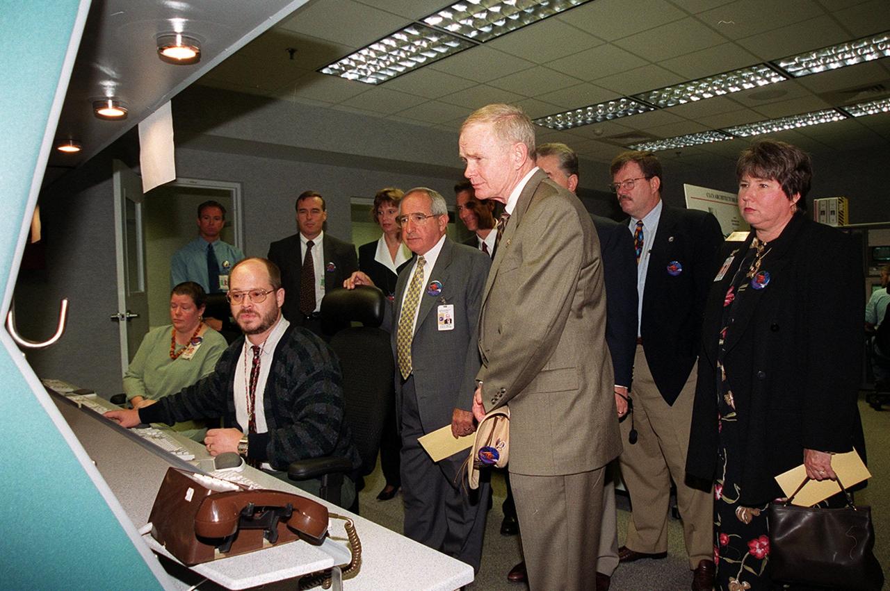
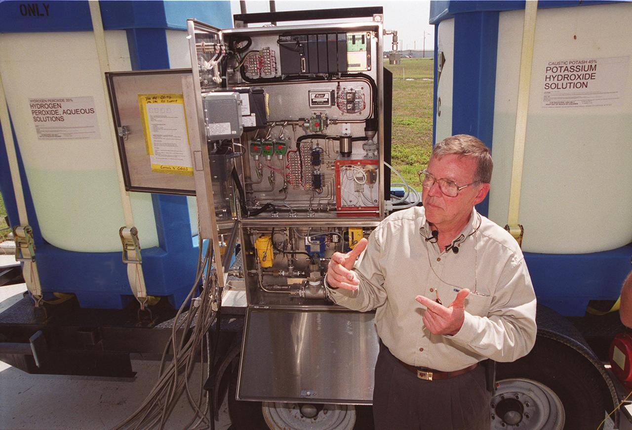
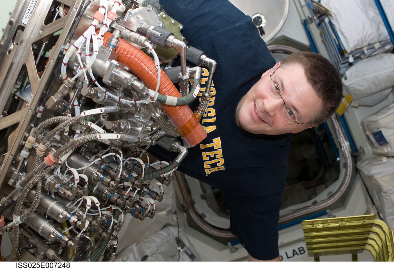
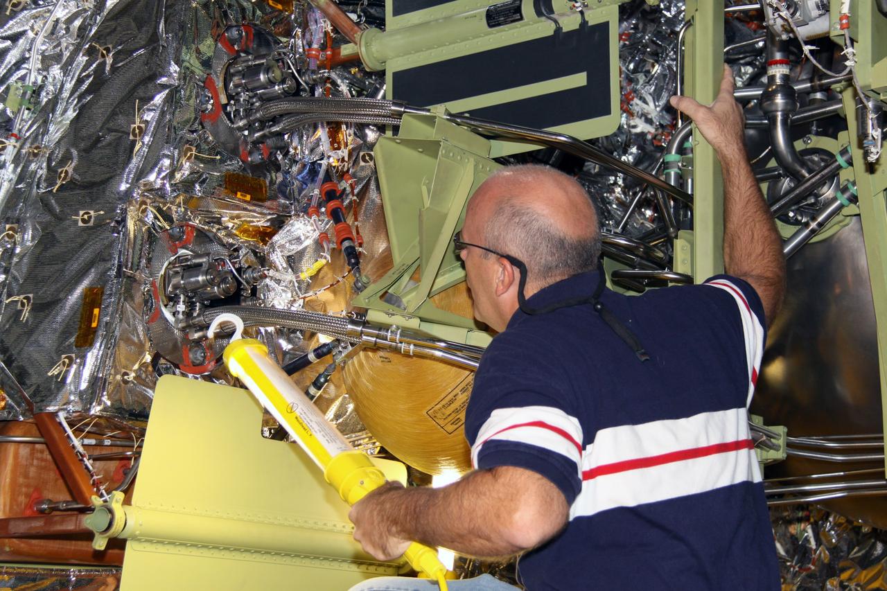
KSC00pp0511
KENNEDY SPACE CENTER, FLA. -- Clyde Parrish, a NASA/KSC engineer, explains how the fertilizer scrubber control panel (center) works to turn nitrogen tetroxide vapor into fertilizer, potassium hydroxide. Parrish developed the system, which uses a "scrubber," to capture nitrogen tetroxide vapor that develops as a by-product when it is transferred from ground storage tanks into the Shuttle storage tanks. Nitrogen tetroxide is used as the oxidizer for the hypergolic propellant in the Shuttle's on-orbit reaction control system. The scrubber then uses hydrogen peroxide to produce nitric acid, which, after adding potassium hydroxide, converts to potassium nitrate. The resulting fertilizer will be used on the orange groves that KSC leases to outside companies
KSC-00pp0511
The upper stage for NASA’s Artemis II SLS (Space Launch System) rocket sits in the transfer aisle of the Vehicle Assembly Building at NASA’s Kennedy Space Center in Florida on Wednesday, April 16, 2025, after teams with the agency’s Exploration Ground Systems Program transported the four-story propulsion system from the spaceport’s Multi-Payload Processing Facility (MPPF). Technicians fueled the SLS upper stage, known as the interim cryogenic propulsion stage, with hydrazine for its reaction control system at the MPPF and will now integrate the four-story propulsion system with SLS rocket elements atop mobile launcher 1.
Artemis II ICPS integration Move from MPPF to VAB
Teams with NASA’s Exploration Ground Systems Program transport the upper stage for the agency’s Artemis II SLS (Space Launch System) rocket from the Multi-Payload Processing Facility (MPPF) at NASA’s Kennedy Space Center in Florida to the spaceport’s Vehicle Assembly Building on Wednesday, April 16, 2025. Technicians fueled the SLS upper stage, known as the interim cryogenic propulsion stage, with hydrazine for its reaction control system at the MPPF and will now integrate the four-story propulsion system with SLS rocket elements atop mobile launcher 1.
Artemis II ICPS integration Move from MPPF to VAB
ISS025-E-007248 (13 Oct. 2010) --- In the Tranquility node aboard the International Space Station, NASA astronaut Doug Wheelock, Expedition 25 commander, works to install the new Sabatier system that will extract more water out of the ISS atmosphere. Sabatier will create water from the byproducts of the station?s Oxygen Generation System and Carbon Dioxide Removal Assembly. Under contract to NASA, Hamilton Sundstrand supplied the flight hardware and operational support for a Sabatier-reaction based system that operates as part of the station?s Environmental Control and Life Support System.
Sabatier
Teams with NASA’s Exploration Ground Systems Program transport the upper stage for the agency’s Artemis II SLS (Space Launch System) rocket from the Multi-Payload Processing Facility (MPPF) at NASA’s Kennedy Space Center in Florida to the spaceport’s Vehicle Assembly Building on Wednesday, April 16, 2025. Technicians fueled the SLS upper stage, known as the interim cryogenic propulsion stage, with hydrazine for its reaction control system at the MPPF and will now integrate the four-story propulsion system with SLS rocket elements atop mobile launcher 1.
Artemis II ICPS integration Move from MPPF to VAB
CAPE CANAVERAL, Fla. – The forward reaction control system, or FRCS, will be removed from space shuttle Endeavour's forward fuselage nose area in NASA Kennedy Space Center's Orbiter Processing Facility 2.  The FRCS provides the thrust for attitude (rotational) maneuvers (pitch, yaw and roll) and for small velocity changes along the orbiter axis (translation maneuvers). Endeavour is designated as the shuttle for the STS-130 mission, targeted for launch in February 2010.  Photo credit: NASA/Jack Pfaller
KSC-2009-4792
KENNEDY SPACE CENTER, FLA.  - In the Orbiter Processing Facility, the Forward Reaction Control System (FRCS) is lifted by an overhead crane for installation in Discovery.  Located in the forward fuselage nose area, the FRCS provides the thrust for attitude (rotational) maneuvers (pitch, yaw and roll) and for small velocity changes along the orbiter axis (translation maneuvers).  Discovery is designated as the Return to Flight vehicle for mission STS-114, no earlier than March 2005.
KSC-04pd1331
KENNEDY SPACE CENTER, FLA. -    In Orbiter Processing Facility Bay 1, technicians work on the Forward Reaction Control System (FRCS) of space shuttle Atlantis as it sits in the transfer aisle prior to installation.  The FRCS provides the thrust for attitude (rotational) maneuvers (pitch, yaw and roll) and for small velocity changes along the orbiter axis (translation maneuvers).  Processing of Atlantis is under way for mission STS-115, the 19th flight to the International Space Station.
KSC-05pd2546
CAPE CANAVERAL, Fla. – The forward reaction control system, or FRCS, will be removed from space shuttle Endeavour's forward fuselage nose area in NASA Kennedy Space Center's Orbiter Processing Facility 2.  The FRCS provides the thrust for attitude (rotational) maneuvers (pitch, yaw and roll) and for small velocity changes along the orbiter axis (translation maneuvers). Endeavour is designated as the shuttle for the STS-130 mission, targeted for launch in February 2010.  Photo credit: NASA/Jack Pfaller
KSC-2009-4791
KENNEDY SPACE CENTER, FLA.  - In the Orbiter Processing Facility, the Forward Reaction Control System (FRCS) is lowered toward Discovery’s forward fuselage nose area where it will be installed.  The FRCS provides the thrust for attitude (rotational) maneuvers (pitch, yaw and roll) and for small velocity changes along the orbiter axis (translation maneuvers).  Discovery is designated as the Return to Flight vehicle for mission STS-114, no earlier than March 2005.
KSC-04pd1332
STS080-360-002 (19 Nov.-7 Dec. 1996) --- From the commander's station on the port side of the space shuttle Columbia's forward flight deck, astronaut Kenneth D. Cockrell prepares for a minor firing of Reaction Control System (RCS) engines during operations with the Wake Shield Facility (WSF). The activity was recorded with a 35mm camera on flight day seven. The commander is attired in a liquid-cooled biological garment.
Cockrell and Rominger go through de-orbit preparations in the flight deck
CAPE CANAVERAL, Fla. – In NASA Kennedy Space Center's Orbiter Processing Facility 2, workers remove the forward reaction control system, or FRCS, from space shuttle Endeavour's forward fuselage nose area. The FRCS provides the thrust for attitude (rotational) maneuvers (pitch, yaw and roll) and for small velocity changes along the orbiter axis (translation maneuvers). Endeavour is designated as the shuttle for the STS-130 mission, targeted for launch in February 2010.  Photo credit: NASA/Jack Pfaller
KSC-2009-4796
KENNEDY SPACE CENTER, FLA. -   In Orbiter Processing Facility Bay 1, technicians work on the Forward Reaction Control System (FRCS) of space shuttle Atlantis as it sits in the transfer aisle prior to installation.  The FRCS provides the thrust for attitude (rotational) maneuvers (pitch, yaw and roll) and for small velocity changes along the orbiter axis (translation maneuvers).  Processing of Atlantis is under way for mission STS-115, the 19th flight to the International Space Station.
KSC-05pd2545
KENNEDY SPACE CENTER, FLA. -    The Forward Reaction Control System (FRCS) of space shuttle Atlantis sits in the transfer aisle of Orbiter Processing Facility Bay 1 in anticipation of being installed. The FRCS provides the thrust for attitude (rotational) maneuvers (pitch, yaw and roll) and for small velocity changes along the orbiter axis (translation maneuvers).  Processing of Atlantis is under way for mission STS-115, the 19th flight to the International Space Station.
KSC-05pd2538
KENNEDY SPACE CENTER, FLA.  - Workers in the Orbiter Processing Facility stand by as a crane lifts the Forward Reaction Control System (FRCS) for installation in Discovery.  Located in the forward fuselage nose area, the FRCS provides the thrust for attitude (rotational) maneuvers (pitch, yaw and roll) and for small velocity changes along the orbiter axis (translation maneuvers).  Discovery is designated as the Return to Flight vehicle for mission STS-114, no earlier than March 2005.
KSC-04pd1330
Mike Ciannilli, at left, the Apollo, Challenger, Columbia Lessons Learned Program manager, presents a certificate to John Tribe, retired, Apollo 1 Reaction and Control System lead engineer, during the Apollo 1 Lessons Learned presentation in the Training Auditorium at NASA's Kennedy Space Center in Florida. The theme of the program was "To there and Back Again." The event helped pay tribute to the Apollo 1 crew, Gus Grissom, Ed White II, and Roger Chaffee.
Apollo 1 Lessons Learned Show
CAPE CANAVERAL, Fla. – In NASA Kennedy Space Center's Orbiter Processing Facility 2, a worker removes the forward reaction control system, or FRCS, from space shuttle Endeavour's forward fuselage nose area. The FRCS provides the thrust for attitude (rotational) maneuvers (pitch, yaw and roll) and for small velocity changes along the orbiter axis (translation maneuvers). Endeavour is designated as the shuttle for the STS-130 mission, targeted for launch in February 2010.  Photo credit: NASA/Jack Pfaller
KSC-2009-4795
KENNEDY SPACE CENTER, FLA. -  At NASA’s Kennedy Space Center, the 2004 class of astronaut candidates get a close look  at the Forward Reaction Control System on Space Shuttle Discovery in the Vehicle Assembly Building (VAB).  Talking to them at left is Ken Tenbusch, VAB Operations manager. The class of 14 candidates includes three candidates from the Japan Aerospace Exploration Agency as well as three educator astronauts, who were school teachers chosen from thousands of applicants.
KSC-05pd-0581
KENNEDY SPACE CENTER, FLA.  - Workers in the Orbiter Processing Facility watch closely as Discovery’s Forward Reaction Control System (FRCS) is lowered into position in the orbiter’s forward fuselage nose area.  The FRCS provides the thrust for attitude (rotational) maneuvers (pitch, yaw and roll) and for small velocity changes along the orbiter axis (translation maneuvers).  Discovery is designated as the Return to Flight vehicle for mission STS-114, no earlier than March 2005.
KSC-04pd1334
KENNEDY SPACE CENTER, FLA. -   The Forward Reaction Control System (FRCS) of space shuttle Atlantis sits in the transfer aisle of Orbiter Processing Facility Bay 1 in anticipation of being installed.  The FRCS provides the thrust for attitude (rotational) maneuvers (pitch, yaw and roll) and for small velocity changes along the orbiter axis (translation maneuvers).  Processing of Atlantis is under way for mission STS-115, the 19th flight to the International Space Station.
KSC-05pd2536
KENNEDY SPACE CENTER, FLA.  - Workers in the Orbiter Processing Facility watch closely as Discovery’s Forward Reaction Control System (FRCS) is lowered into position in the orbiter’s forward fuselage nose area.  The FRCS provides the thrust for attitude (rotational) maneuvers (pitch, yaw and roll) and for small velocity changes along the orbiter axis (translation maneuvers).  Discovery is designated as the Return to Flight vehicle for mission STS-114, no earlier than March 2005.
KSC-04pd1333
KENNEDY SPACE CENTER, FLA. -   In Orbiter Processing Facility Bay 1, technicians work on the Forward Reaction Control System (FRCS) of space shuttle Atlantis as it sits in the transfer aisle prior to installation.  The FRCS provides the thrust for attitude (rotational) maneuvers (pitch, yaw and roll) and for small velocity changes along the orbiter axis (translation maneuvers).  Processing of Atlantis is under way for mission STS-115, the 19th flight to the International Space Station.
KSC-05pd2544
NASA Kennedy Space Center Director Bob Cabana, at left, moderates a panel discussion during the Apollo 1 Lessons Learned event in the Training Auditorium at NASA’s Kennedy Space Center in Florida. The theme of the presentation was "To There and Back Again." Answering questions are Ernie Reyes, retired, Apollo 1 senior operations engineer; and John Tribe, retired, Apollo 1 Reaction and Control System lead engineer. The event helped pay tribute to the Apollo 1 crew, Gus Grissom, Ed White II, and Roger Chaffee.
Apollo 1 Lessons Learned Show
CAPE CANAVERAL, Fla. – In NASA Kennedy Space Center's Orbiter Processing Facility 2, workers prepare to remove the forward reaction control system, or FRCS, from space shuttle Endeavour's forward fuselage nose area. The FRCS provides the thrust for attitude (rotational) maneuvers (pitch, yaw and roll) and for small velocity changes along the orbiter axis (translation maneuvers). Endeavour is designated as the shuttle for the STS-130 mission, targeted for launch in February 2010.  Photo credit: NASA/Jack Pfaller
KSC-2009-4793
John Tribe, retired, Apollo 1 Reaction and Control System lead engineer, answers questions during the Apollo 1 Lessons Learned event in the Training Auditorium at NASA’s Kennedy Space Center in Florida. The theme of the presentation was "To There and Back Again." The event helped pay tribute to the Apollo 1 crew, Gus Grissom, Ed White II, and Roger Chaffee.
Apollo 1 Lessons Learned Show
CAPE CANAVERAL, Fla. – In NASA Kennedy Space Center's Orbiter Processing Facility 2, workers begin removing the forward reaction control system, or FRCS, from space shuttle Endeavour's forward fuselage nose area. The FRCS provides the thrust for attitude (rotational) maneuvers (pitch, yaw and roll) and for small velocity changes along the orbiter axis (translation maneuvers). Endeavour is designated as the shuttle for the STS-130 mission, targeted for launch in February 2010.  Photo credit: NASA/Jack Pfaller
KSC-2009-4794
KENNEDY SPACE CENTER, FLA. -   The Forward Reaction Control System (FRCS) of space shuttle Atlantis sits in the transfer aisle of Orbiter Processing Facility Bay 1 in anticipation of being installed. The FRCS provides the thrust for attitude (rotational) maneuvers (pitch, yaw and roll) and for small velocity changes along the orbiter axis (translation maneuvers).  Processing of Atlantis is under way for mission STS-115, the 19th flight to the International Space Station.
KSC-05pd2537
KENNEDY SPACE CENTER, FLA. -  In the Orbiter Processing Facility, the left-hand Orbital Maneuvering System (OMS) pod is lifted at an angle from the transporter below.  The OMS pod will be installed on the orbiter Discovery.  The Orbital Maneuvering System provides the thrust for orbit insertion, orbit circularization, orbit transfer, rendezvous, deorbit, abort to orbit and abort once around.  It can provide up to 1,000 pounds of propellant to the aft reaction control system.  Each pod contains one OMS engine and the hardware needed to pressurize, store and distribute the propellants to perform the velocity maneuvers.
KSC-04pd0944
KENNEDY SPACE CENTER, FLA.  - Technicians install the left Orbital Maneuvering System (OMS) pod on Space Shuttle Atlantis in Orbiter Process Facility bay 1. The Orbital Maneuvering System provides the thrust for orbit insertion, orbit circularization, orbit transfer, rendezvous, deorbit, abort to orbit and abort once around. It can provide up to 1,000 pounds of propellant to the aft reaction control system. Each pod contains one OMS engine and the hardware needed to pressurize, store and distribute the propellants to perform the velocity maneuvers.  Atlantis is the designated orbiter to fly on mission STS-121.  The mission has a launch window of July 12 - July 31.
KSC-05pd-0299
KENNEDY SPACE CENTER, FLA.  - Technicians discuss the left Orbital Maneuvering System (OMS) pod installed on Space Shuttle Atlantis today in Orbiter Process Facility bay 1. The Orbital Maneuvering System provides the thrust for orbit insertion, orbit circularization, orbit transfer, rendezvous, deorbit, abort to orbit and abort once around. It can provide up to 1,000 pounds of propellant to the aft reaction control system. Each pod contains one OMS engine and the hardware needed to pressurize, store and distribute the propellants to perform the velocity maneuvers.  Atlantis is the designated orbiter to fly on mission STS-121.  The mission has a launch window of July 12 - July 31.
KSC-05pd-0298
KENNEDY SPACE CENTER, FLA. -  In the Orbiter Processing Facility, workers on an upper level watch as the left-hand Orbital Maneuvering System (OMS) pod is lifted high to maneuver it toward the orbiter Discovery for installation.  The Orbital Maneuvering System provides the thrust for orbit insertion, orbit circularization, orbit transfer, rendezvous, deorbit, abort to orbit and abort once around.  It can provide up to 1,000 pounds of propellant to the aft reaction control system.  Each pod contains one OMS engine and the hardware needed to pressurize, store and distribute the propellants to perform the velocity maneuvers.
KSC-04pd0946
KENNEDY SPACE CENTER, FLA. -  In the Orbiter Processing Facility, the left-hand Orbital Maneuvering System (OMS) pod (seen from the front) is lifted off its transporter.  The OMS pod will be installed on the orbiter Discovery.  The Orbital Maneuvering System provides the thrust for orbit insertion, orbit circularization, orbit transfer, rendezvous, deorbit, abort to orbit and abort once around.  It can provide up to 1,000 pounds of propellant to the aft reaction control system.  Each pod contains one OMS engine and the hardware needed to pressurize, store and distribute the propellants to perform the velocity maneuvers.
KSC-04pd0941
KENNEDY SPACE CENTER, FLA. - In the Orbiter Processing Facility, workers stand by as the left-hand Orbital Maneuvering System (OMS) pod is maneuvered toward the engine interfaces on the orbiter Discovery for installation.  The Orbital Maneuvering System provides the thrust for orbit insertion, orbit circularization, orbit transfer, rendezvous, deorbit, abort to orbit and abort once around.  It can provide up to 1,000 pounds of propellant to the aft reaction control system.  Each pod contains one OMS engine and the hardware needed to pressurize, store and distribute the propellants to perform the velocity maneuvers.
KSC-04pd0949
KENNEDY SPACE CENTER, FLA. -  In the Orbiter Processing Facility, workers check the lifting of the left-hand Orbital Maneuvering System (OMS) pod.  The OMS pod will be installed on the orbiter Discovery.  The Orbital Maneuvering System provides the thrust for orbit insertion, orbit circularization, orbit transfer, rendezvous, deorbit, abort to orbit and abort once around.  It can provide up to 1,000 pounds of propellant to the aft reaction control system.  Each pod contains one OMS engine and the hardware needed to pressurize, store and distribute the propellants to perform the velocity maneuvers.
KSC-04pd0943