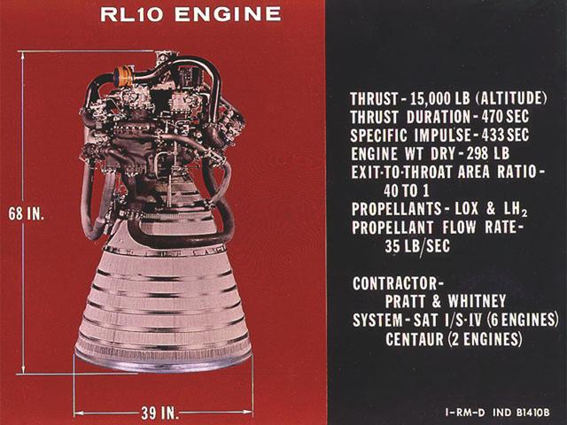
RL-10 engine characteristics. The RL-10 engine was developed under the management of the Marshall Space Flight Center (MSFC) to power the Saturn I upper stage (S-IV stage). The six RL-10 engines, which used liquid hydrogen and liquid oxygen as propellants, were arranged in a circle on the aft end of the S-IV stage.
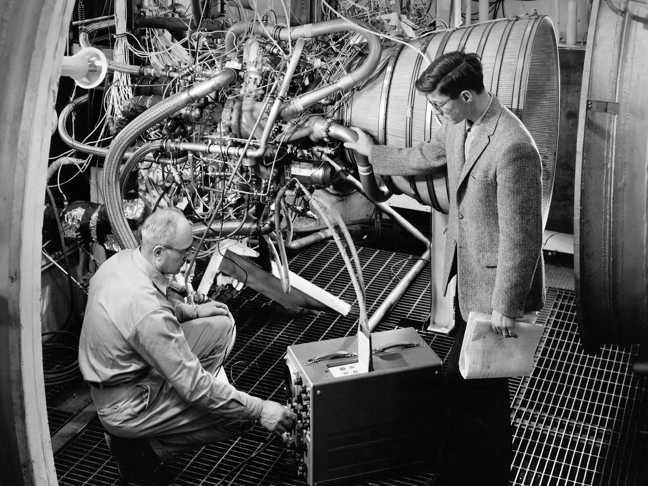
Lead Test Engineer John Kobak (right) and a technician use an oscilloscope to test the installation of a Pratt and Whitney RL-10 engine in the Propulsion Systems Laboratory at the National Aeronautics and Space Administration (NASA) Lewis Research Center. In 1955 the military asked Pratt and Whitney to develop hydrogen engines specifically for aircraft. The program was canceled in 1958, but Pratt and Whitney decided to use the experience to develop a liquid-hydrogen rocket engine, the RL-10. Two of the 15,000-pound-thrust RL-10 engines were used to power the new Centaur second-stage rocket. Centaur was designed to carry the Surveyor spacecraft on its mission to soft-land on the Moon. Pratt and Whitney ran into problems while testing the RL-10 at their facilities. NASA Headquarters assigned Lewis the responsibility for investigating the RL-10 problems because of the center’s long history of liquid-hydrogen development. Lewis’ Chemical Rocket Division began a series of tests to study the RL-10 at its Propulsion Systems Laboratory in March 1960. The facility contained two test chambers that could study powerful engines in simulated altitude conditions. The first series of RL-10 tests in early 1961 involved gimballing the engine as it fired. Lewis researchers were able to yaw and pitch the engine to simulate its behavior during a real flight.
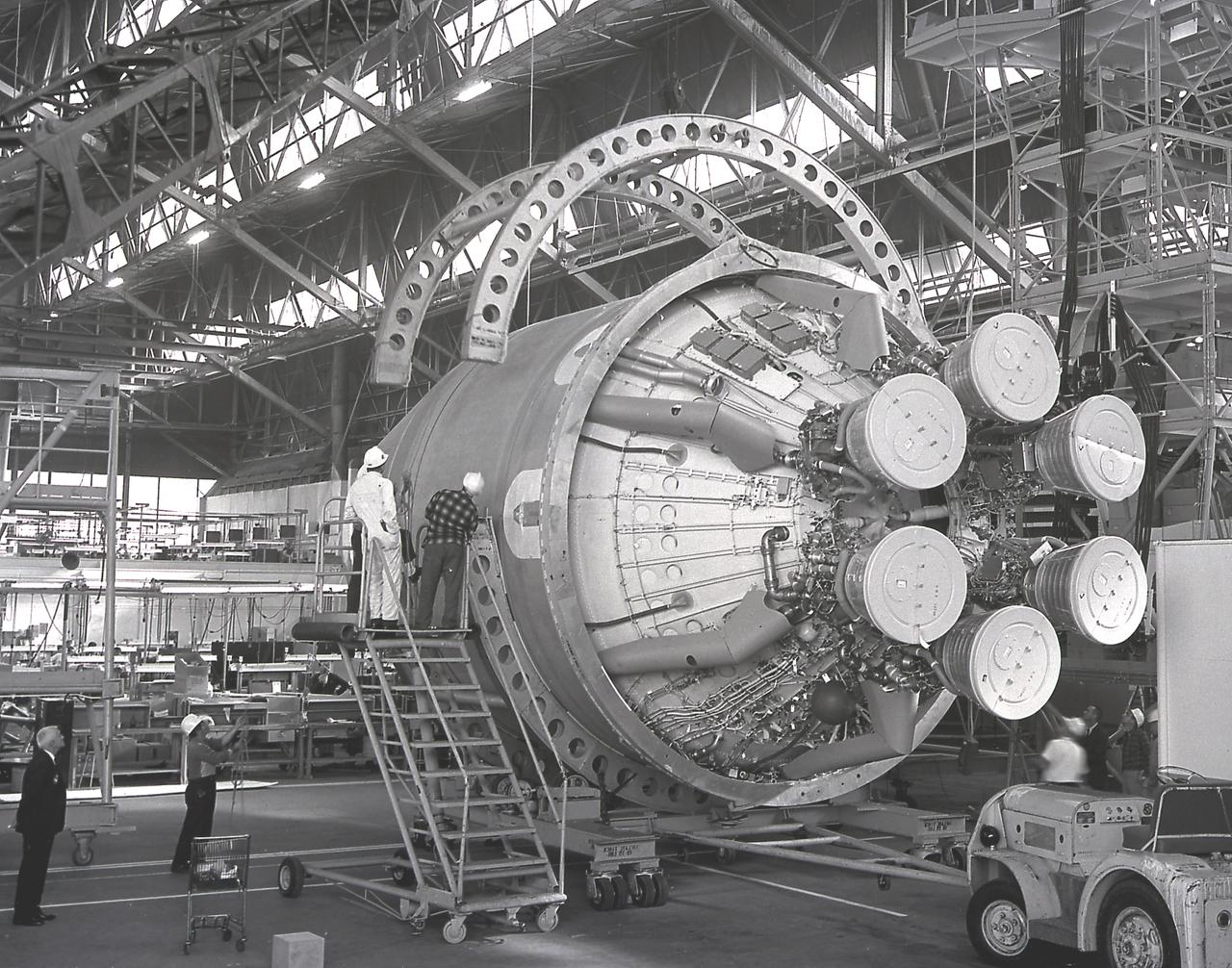
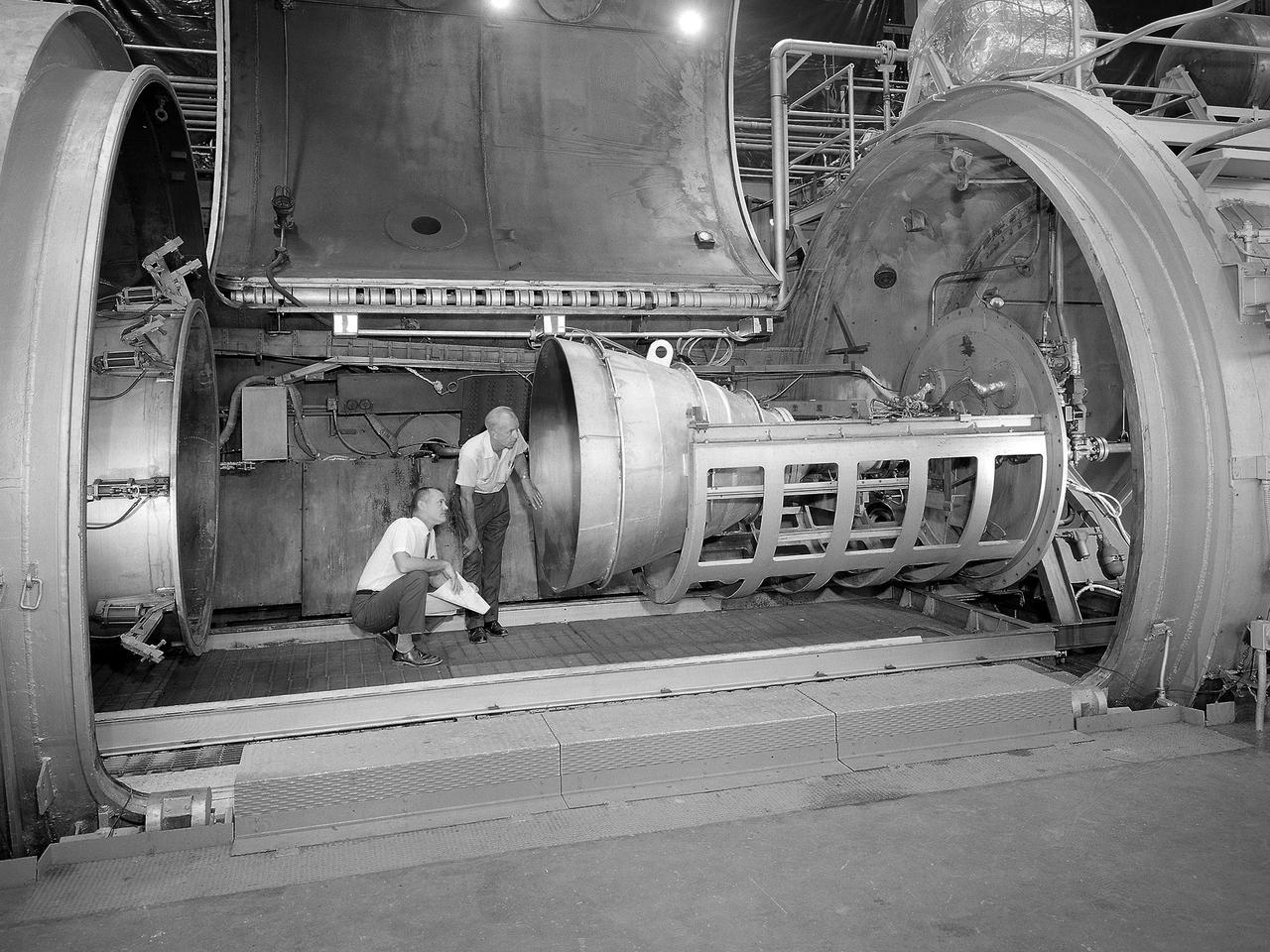
The Saturn I S-IV stage (second stage) for the SA-7 mission being prepared for shipment to Cape Canaveral, Florida. The S-IV stage had six RL-10 engines, which used liquid hydrogen and liquid oxygen as its propellants, arranged in a circle. Each RL-10 engine produced a thrust of 15,000 pounds for a total combined thrust of 90,000 pounds. The SA-7 mission was launched on September 18, 1964 from Cape Canaveral, Florida, and its S-IV stage made the second orbital flight.
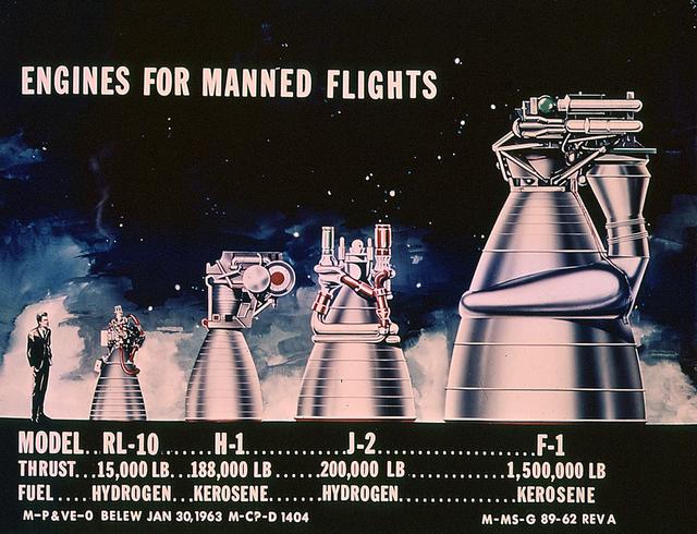
This drawing clearly shows the comparative sizes of the rocket engines used to launch the Saturn vehicles. The RL-10 and the H-1 engines were used to launch the Saturn I rockets. The J-2 engine was used on the second stage of Saturn IB and the second and third stages of Saturn V. The F-1 engine was used on the first stage of the Saturn V.
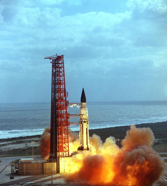
The launch of the SA-5 on January 29, 1964 was the fifth Saturn I launch vehicle. The SA-5 marked a number of firsts in the Marshall Space Flight Center-managed Saturn development program, including the first flight of Saturn I Block II vehicle with eight aerodynamic fins at the bottom of the S-I stage (first stage) for enhanced stability in flight. This also was the first flight of a live S-IV (second or upper) stage with the cluster of six liquid hydrogen-fueled RL-10 engines. the first successful second stage separation, and the first use of the Launch Complex 37.
DELTA 3 RL-10 B-2 ENGINE FIRING
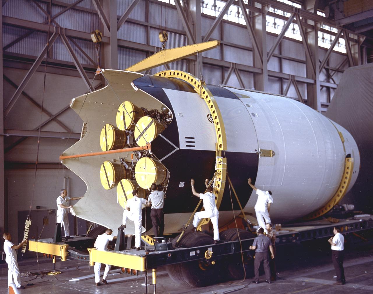
The Saturn I S-IV stage (second stage) assembly for the SA-9 mission underwent the weight and balance test in the hangar building at Cape Canaveral. The S-IV stage had six RL-10 engines which used liquid hydrogen and liquid oxygen as its propellants arranged in a circle. Each RL-10 engine produced a thrust of 15,000 pounds, a total combined thrust of 90,000 pounds. The SA-9 mission was the first Saturn with operational payload Pegasus I, meteoroid detection satellite, and launched on February 16, 1965.
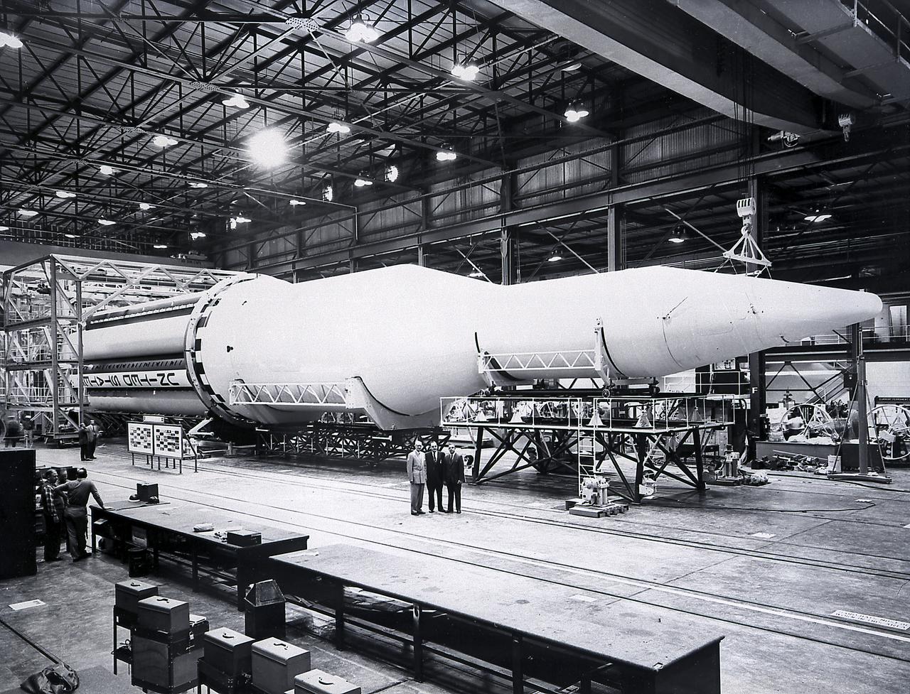
A completed Saturn I launch vehicle in the Fabrication and Assembly Engineering Division at the Marshall Space Flight Center. The Saturn I launch vehicle is composed of an S-I first stage or booster (rear), powered by eight H-1 engines having a thrust of 1,500,000 pounds, followed by a dummy S-IV second stage with six RL-10 engine, with a total thrust of 90,000 pounds.
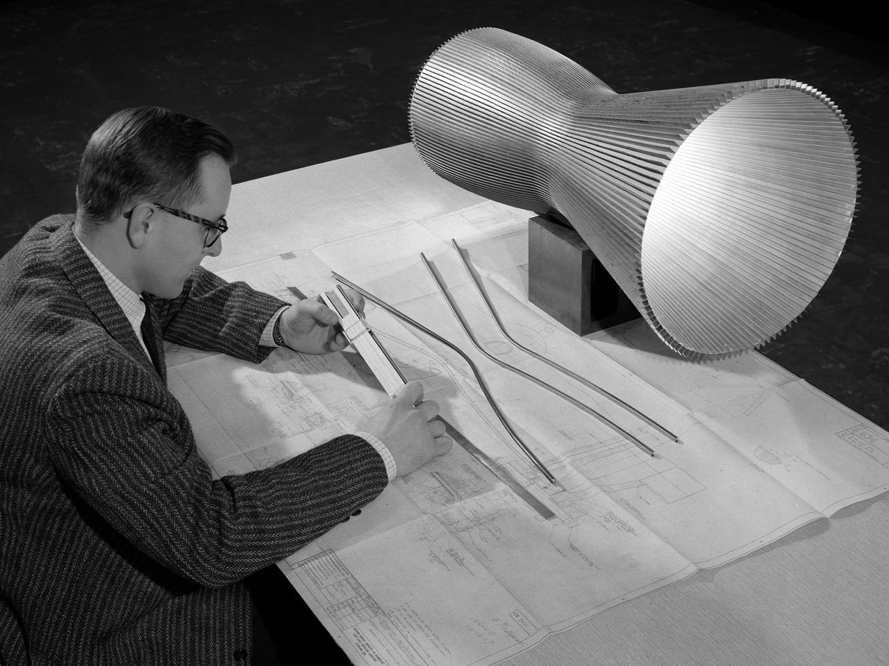
An engineer at the National Aeronautics and Space Administration (NASA) Lewis Research Center examines a drawing showing the assembly and details of a 20,000-pound thrust regeneratively cooled rocket engine. The engine was being designed for testing in Lewis’ new Rocket Engine Test Facility, which began operating in the fall of 1957. The facility was the largest high-energy test facility in the country that was capable of handling liquid hydrogen and other liquid chemical fuels. The facility’s use of subscale engines up to 20,000 pounds of thrust permitted a cost-effective method of testing engines under various conditions. The Rocket Engine Test Facility was critical to the development of the technology that led to the use of hydrogen as a rocket fuel and the development of lightweight, regeneratively-cooled, hydrogen-fueled rocket engines. Regeneratively-cooled engines use the cryogenic liquid hydrogen as both the propellant and the coolant to prevent the engine from burning up. The fuel was fed through rows of narrow tubes that surrounded the combustion chamber and nozzle before being ignited inside the combustion chamber. The tubes are visible in the liner sitting on the desk. At the time, Pratt and Whitney was designing a 20,000-pound thrust liquid-hydrogen rocket engine, the RL-10. Two RL-10s would be used to power the Centaur second-stage rocket in the 1960s. The successful development of the Centaur rocket and the upper stages of the Saturn V were largely credited to the work carried out Lewis.
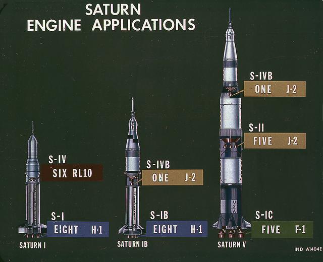
This image illustrates the basic differences between the three Saturn launch vehicles developed by the Marshall Space Flight Center. The Saturn I, consisted of two stages, the S-I (eight H-1 engines) and the S-IV (six RL-10 engines). The Saturn IB (center) also consisted of two stages, the S-IB (eight H-1 engines) and the S-IVB (one J-2 engine). The Saturn V consisted of three stages, the S-IC (five F-1 engines), the S-II (five J-2 engines), and the S-IVB (one J-2 engine).
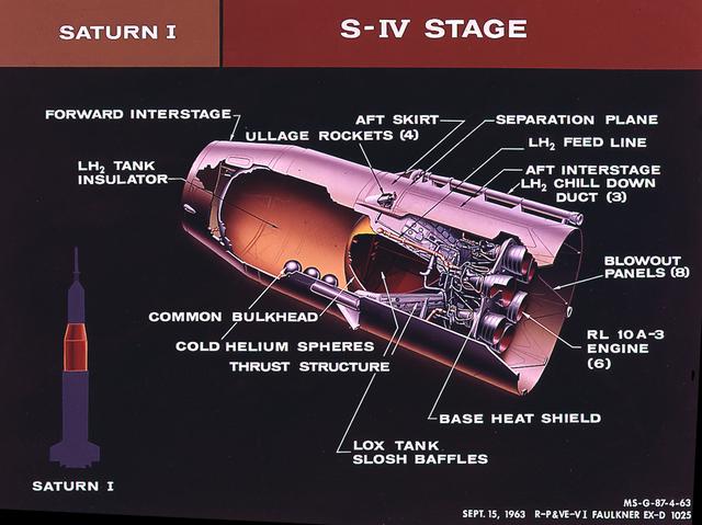
This cutaway of the Saturn I S-IV stage (second stage) illustrates the booster's components. Powered by six RL-10 engines, the S-IV stage was capable of producing 90,000 pounds of thrust. Development of the Saturn S-IV stage by the Marshall Space Flight Center (MSFC) contributed many technological breakthroughs vital to the success of the Apollo lunar program, including the use of liquid hydrogen as a propellant.
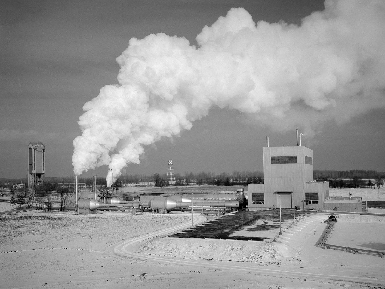
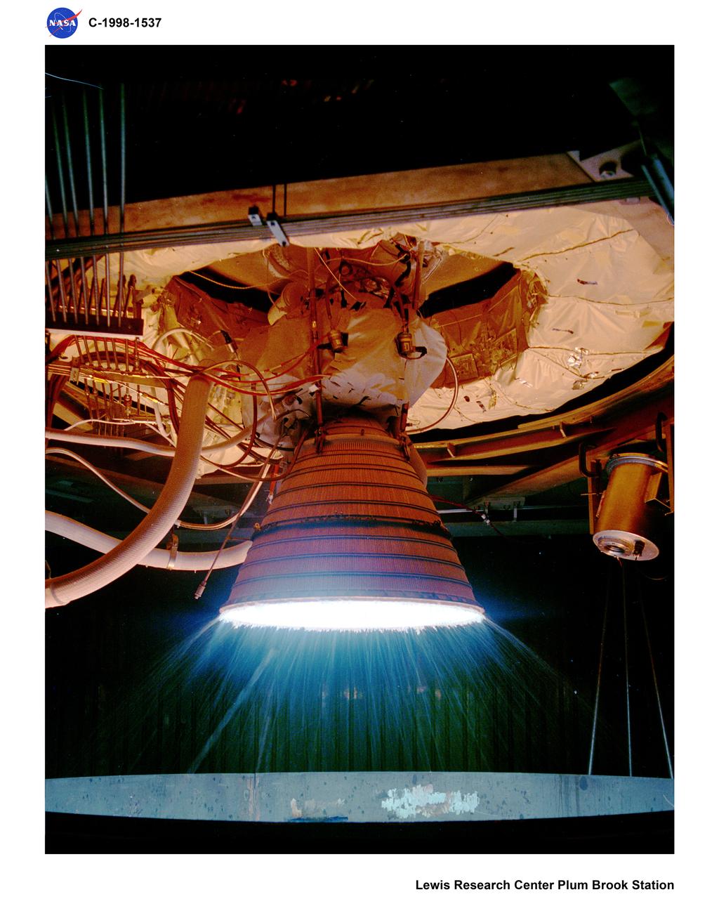
The Space Propulsion Research Facility, better known as B-2, operating at the National Aeronautics and Space Administration’s (NASA) Plum Brook Station in Sandusky, Ohio. B-2 is the world's only high altitude test facility capable of full-scale rocket engine and launch vehicle system level tests. It was created to test rocket propulsion systems with up to 100,000 pounds of thrust in a simulated space environment. The facility has the unique ability to maintain a vacuum at the rocket’s nozzle while the engine is firing. The rocket fires into a 120-foot deep spray chamber which cools the exhaust before it is ejected outside the facility. B-2 simulated space using giant diffusion pumps to reduce chamber pressure, nitrogen-filled cold walls create cryogenic temperatures, and quartz lamps replicate the radiation of the sun. This photograph shows the facility undergoing check-out runs prior to its first test in late 1969.The 38-foot diameter and 62-foot tall vacuum chamber is inside the high-bay on the right. Below that is a 67-foot diameter and 120-foot deep spray chamber. The hot rocket exhaust is cooled in the chamber by a spray of 250,000 gallons of water per minute. B-2’s first test was a hot firing of Centaur D-1A rocket on December 18, 1969. Since then the facility has fired more than 100 Pratt and Whitney RL-10 engines during the Centaur development, 80 current RL-10B-2 engines for Delta-3 development, and another 12 RL-10B-2s for the Delta 3 Upper Stage.
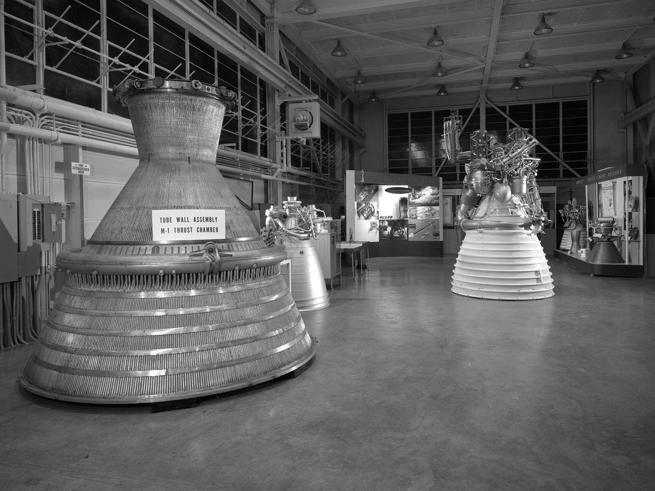
An array of rocket engines displayed in the Propulsion Systems Laboratory for the 1966 Inspection held at the National Aeronautics and Space Administration (NASA) Lewis Research Center. Lewis engineers had been working on chemical, nuclear, and solid rocket engines throughout the 1960s. The engines on display are from left to right: two scale models of the Aerojet M-1, a Rocketdyne J-2, a Pratt and Whitney RL-10, and a Rocketdyne throttleable engine. Also on display are several ejector plates and nozzles. The Chemical Rocket Division resolved issues such as combustion instability and screech, and improved operation of cooling systems and turbopumps. The 1.5-million pound thrust M-1 engine was the largest hydrogen-fueled rocket engine ever created. It was a joint project between NASA Lewis and Aerojet-General. Although much larger in size, the M-1 used technology developed for the RL-10 and J-2. The M-1 program was cancelled in late 1965 due to budget cuts and the lack of a post-Apollo mission. The October 1966 Inspection was the culmination of almost a year of events held to mark the centers’ 25th anniversary. The three‐day Inspection, Lewis’ first since 1957, drew 2000 business, industry, and government executives and included an employee open house. The visitors witnessed presentations at the major facilities and viewed the Gemini VII spacecraft, a Centaur rocket, and other displays in the hangar. In addition, Lewis’ newest facility, the Zero Gravity Facility, was shown off for the first time.
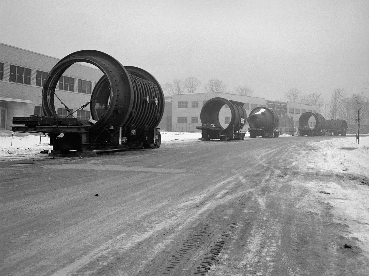
A caravan of large steel castings arrived at the National Advisory Committee for Aeronautics (NACA) Lewis Flight Propulsion Laboratory in January 1951. These pieces would serve as the two 14-foot diameter test chambers in the new Propulsion Systems Laboratory (PSL). NACA Lewis specialized in aircraft engines and offered many engine test facilities. In the late 1940s, however, the NACA realized a larger facility was required to test the newest jet engines. When completed in October 1952, PSL became the nation’s most powerful facility for testing full-scale engines at simulated flight altitudes. NACA engineers began designing the PSL in 1947, and excavations commenced in September 1949. In the spring of 1950, the facility’s supports were erected, and the two large exhaust gas coolers were installed. Work on the Access Building began in early 1951 with the arrival of the large test section pieces, seen in this photograph. The massive pieces were delivered to the area from the Henry Pratt Company by rail and then loaded on a series of flatbed trucks that transported them to Lewis. The nearest vehicle has one of the clamshell access hatches. PSL was initially used to study the jet engines of the early 1950s and ramjets for missile programs such as Navaho and Bomarc. With the advent of the space program in the late 1950s, the facility was used to investigate complex rocket engines, including the Pratt and Whitney RL-10.
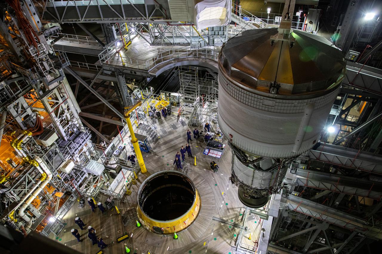
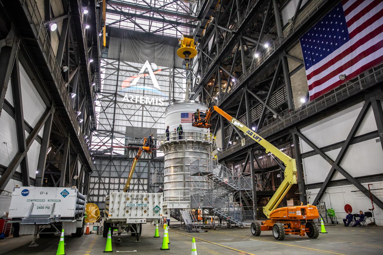
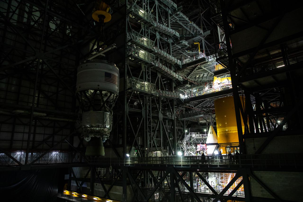
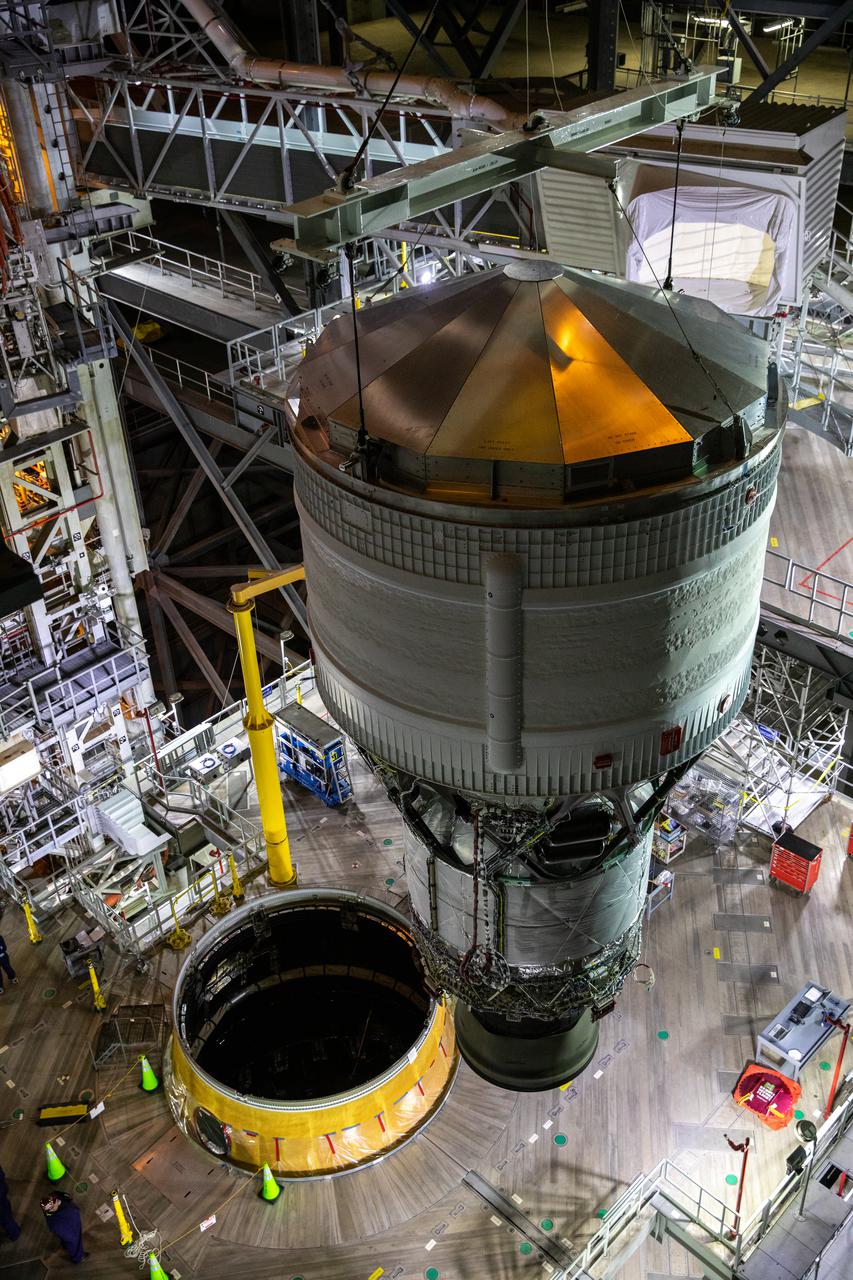
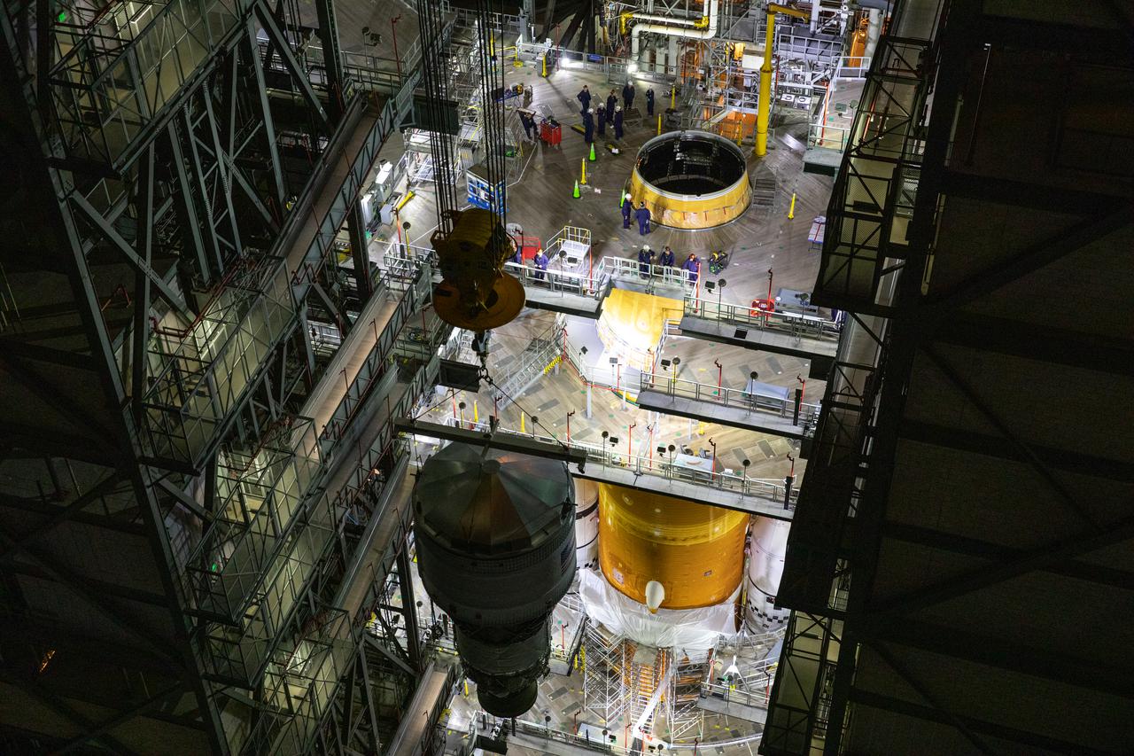
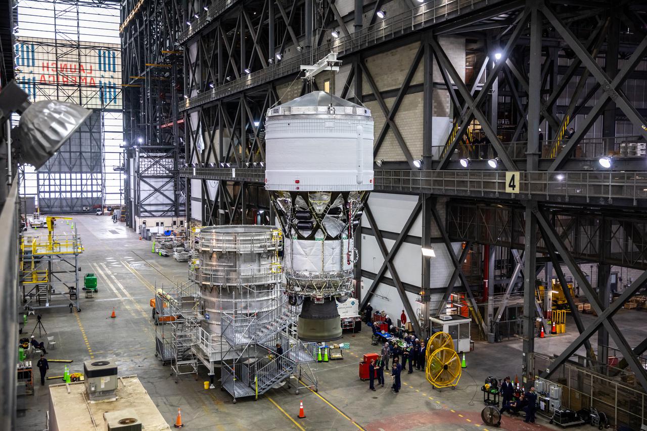
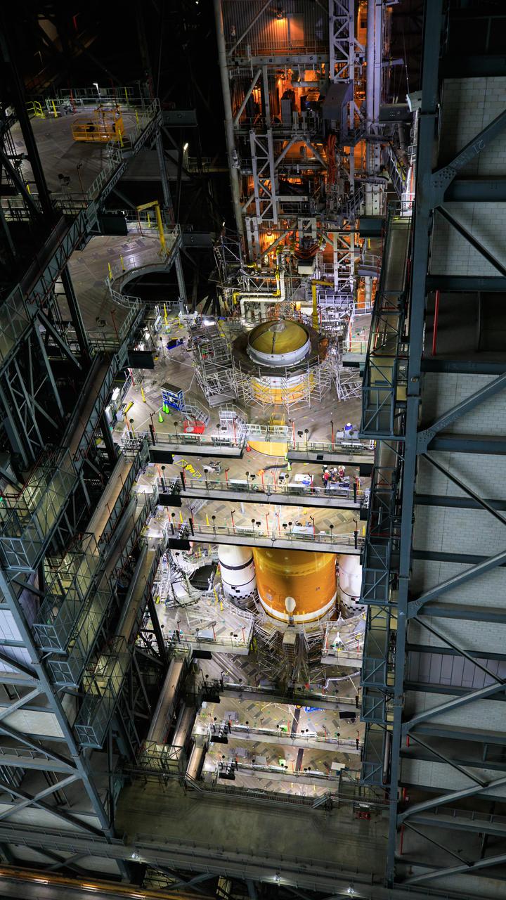
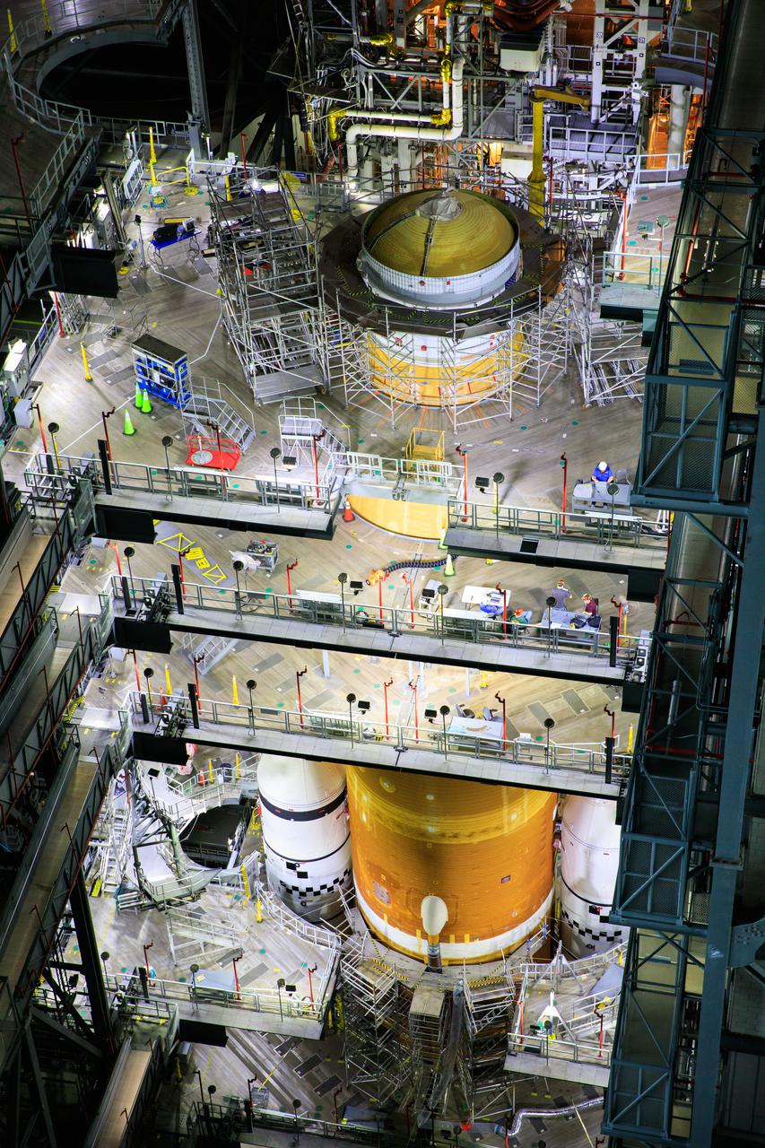
Teams with NASA’s Exploration Ground Systems and contractor Jacobs integrate the interim cryogenic propulsion stage (ICPS) for NASA’s Space Launch System (SLS) rocket with the launch vehicle stage adapter (LVSA) atop the massive SLS core stage in the agency’s Vehicle Assembly Building (VAB) at NASA’s Kennedy Space Center in Florida on July 5, 2021. The ICPS is a liquid oxygen and liquid hydrogen-based system that will fire its RL 10 engine to give the Orion spacecraft the big in-space push needed to fly tens of thousands of miles beyond the Moon. The next component to be stacked on top of ICPS will be the Orion stage adapter, which will connect the ICPS with the spacecraft. Through Artemis, NASA will send the first woman and the first person of color to the lunar surface, as well as establish a sustainable presence on and around the Moon. As the first in an increasingly complex set of missions, Artemis I will test SLS and Orion as an integrated system prior to crewed flights to the Moon.
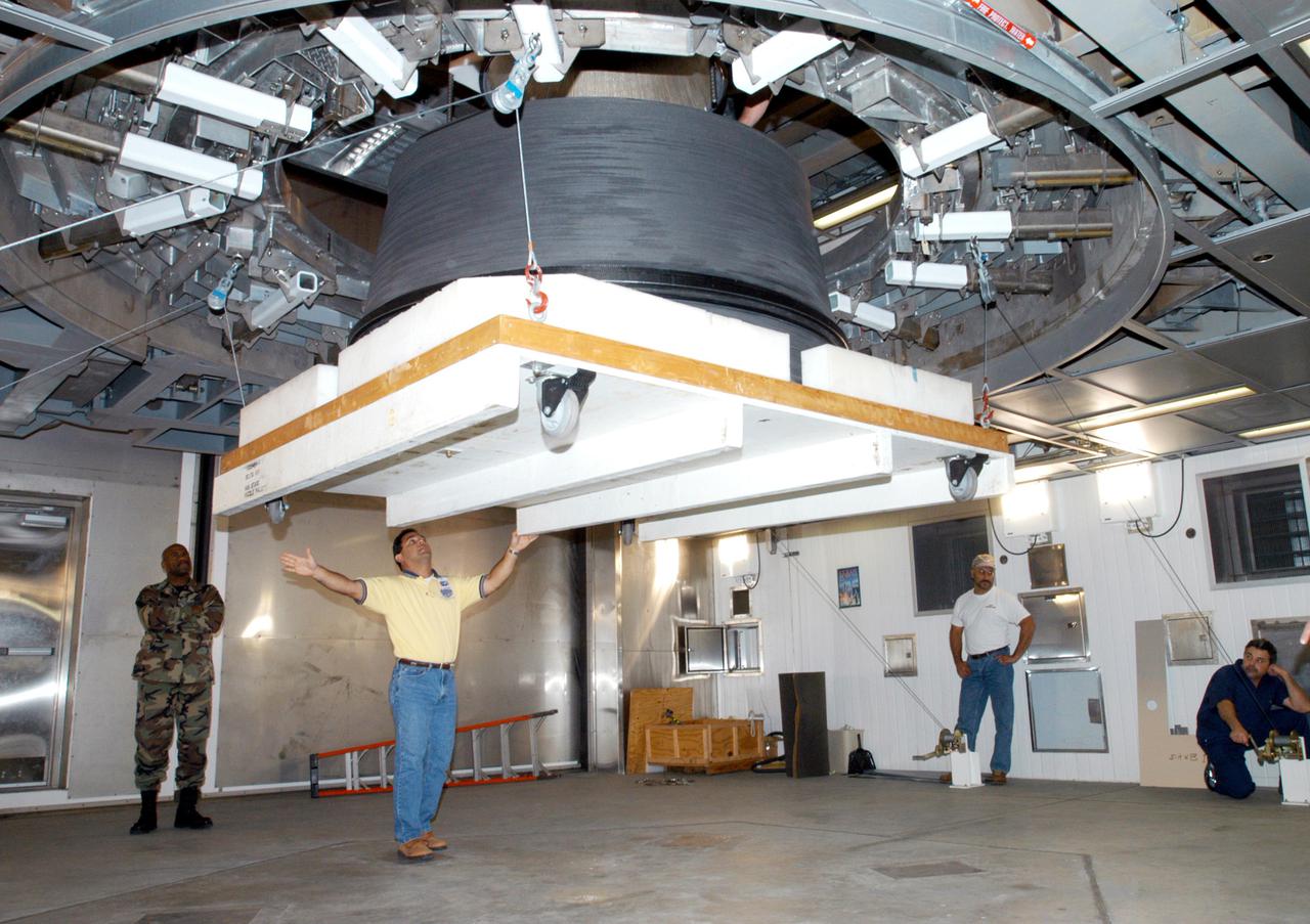
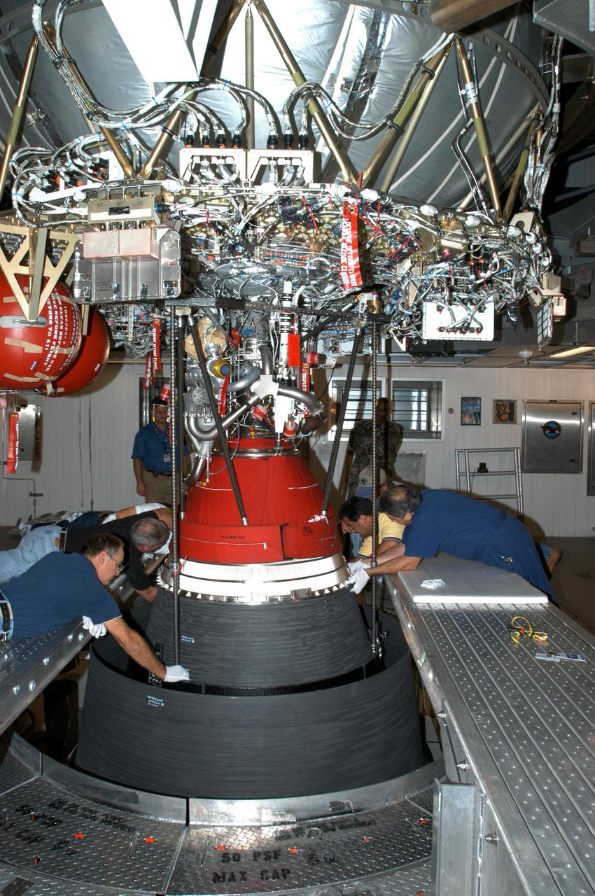
KENNEDY SPACE CENTER, FLA. - At the Delta Operations Center, Leslie Guzman (yellow shirt), with Pratt and Whitney, watches closely as the nozzle for the RL-10 engine is lifted into place on the second stage of the Boeing Delta IV rocket. The Delta IV is the launch vehicle for the Geostationary Operational Environmental Satellite (GOES-N), scheduled to launch in April 2005 from Cape Canaveral Air Force Station. GOES-N is a weather satellite for NASA and NOAA (National Oceanic and Atmospheric Administration). The first in a series of three advanced weather satellites including GOES-O and GOES-P, the GOES-N will provide continuous monitoring necessary for intensive data analysis. It will provide a constant vigil for the atmospheric “triggers” of severe weather conditions such as tornadoes, flash floods, hail storms and hurricanes. When these conditions develop, GOES-N will be able to monitor storm development and track their movements.
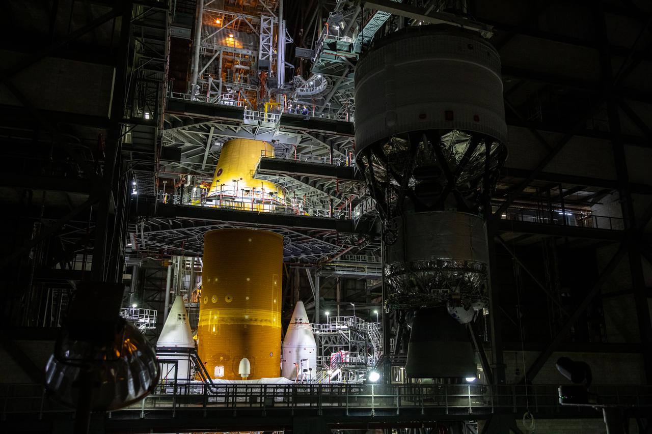
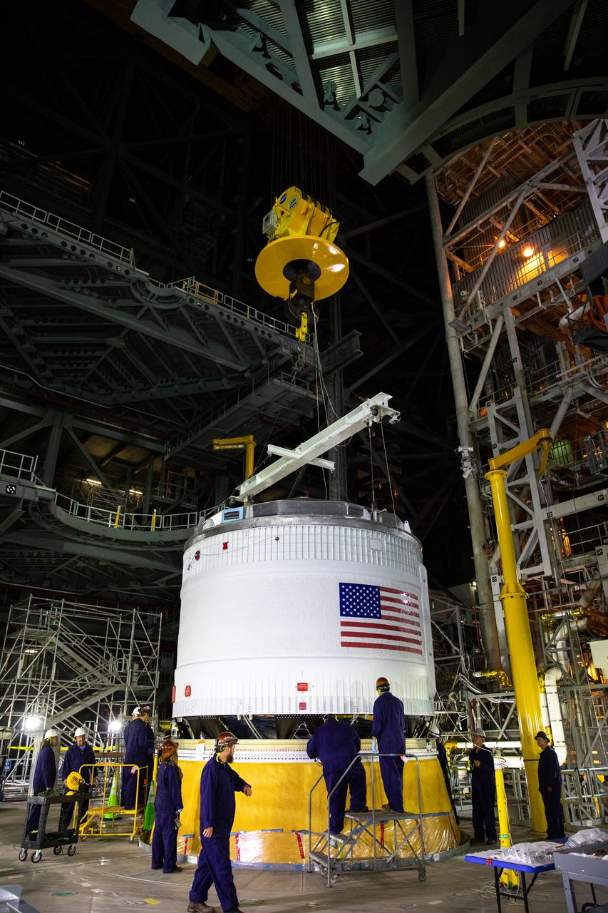
Teams with NASA’s Exploration Ground Systems and contractor Jacobs move the Space Launch System (SLS) rocket’s interim cryogenic propulsion stage (ICPS) into the Vehicle Assembly Building (VAB) at NASA’s Kennedy Space Center in Florida on Saturday, June 19, 2021. After being fueled and serviced inside the Multi-Payload Processing Facility (MPPF), the ICPS will be hoisted into place atop the SLS core stage while its Aerojet Rocketdyne-built RL-10 engine will be protected inside the launch vehicle stage adapter (LVSA) on the mobile launcher in preparation for the launch of Artemis I. The ICPS will provide Orion spacecraft with the push needed for its flight around the Moon. The first in a series of increasingly complex missions, Artemis I will test SLS and the Orion spacecraft as an integrated system prior to crewed flights in which NASA will land the first woman and person of color on the Moon.
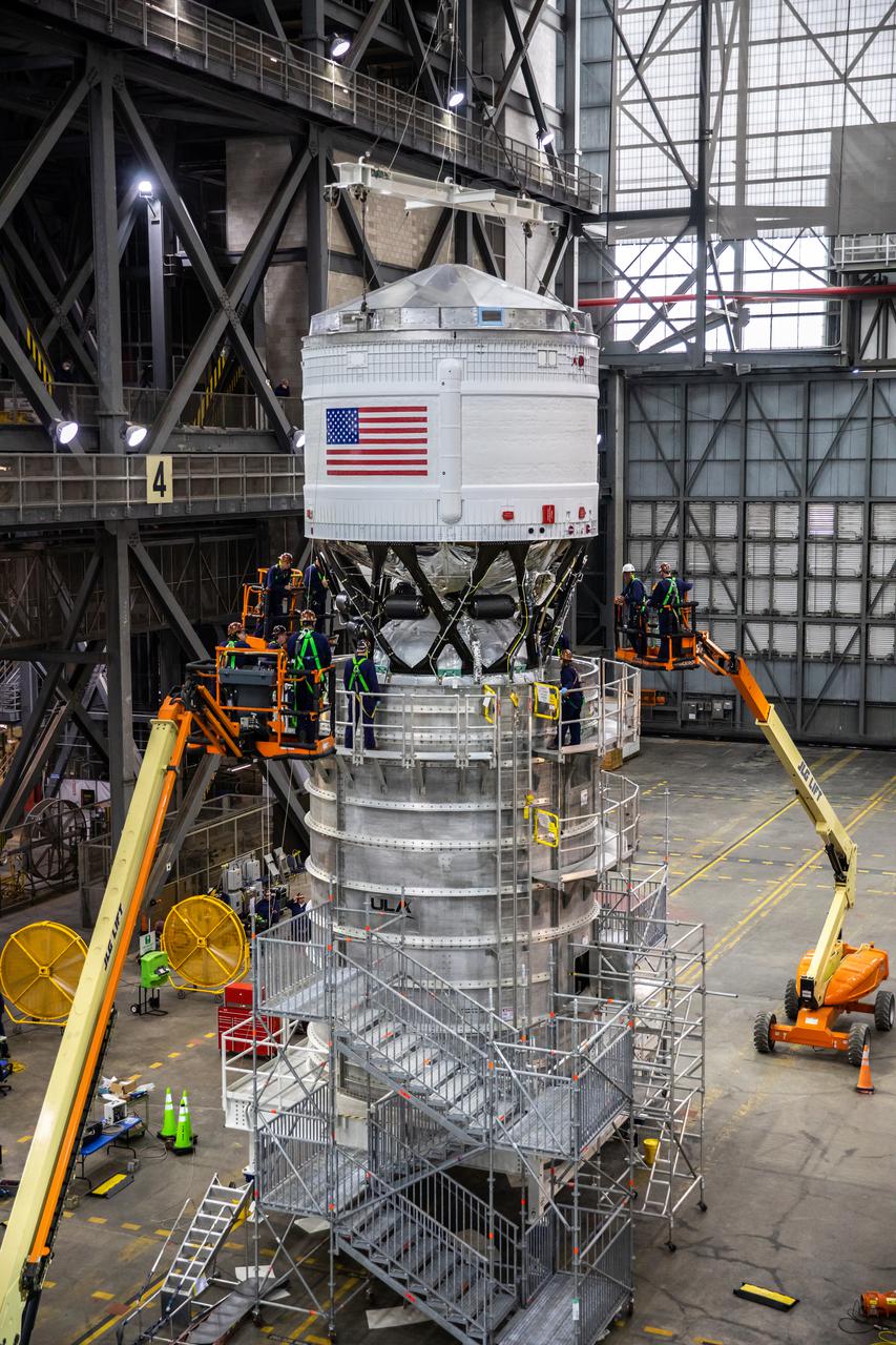
Teams with NASA’s Exploration Ground Systems and contractor Jacobs integrate the interim cryogenic propulsion stage (ICPS) for NASA’s Space Launch System (SLS) rocket with the launch vehicle stage adapter (LVSA) atop the massive SLS core stage in the agency’s Vehicle Assembly Building (VAB) at NASA’s Kennedy Space Center in Florida on July 5, 2021. The ICPS is a liquid oxygen and liquid hydrogen-based system that will fire its RL 10 engine to give the Orion spacecraft the big in-space push needed to fly tens of thousands of miles beyond the Moon. The next component to be stacked on top of ICPS will be the Orion stage adapter, which will connect the ICPS with the spacecraft. Through Artemis, NASA will send the first woman and the first person of color to the lunar surface, as well as establish a sustainable presence on and around the Moon. As the first in an increasingly complex set of missions, Artemis I will test SLS and Orion as an integrated system prior to crewed flights to the Moon.
Teams with NASA’s Exploration Ground Systems and contractor Jacobs integrate the interim cryogenic propulsion stage (ICPS) for NASA’s Space Launch System (SLS) rocket with the launch vehicle stage adapter (LVSA) atop the massive SLS core stage in the agency’s Vehicle Assembly Building (VAB) at NASA’s Kennedy Space Center in Florida on July 5, 2021. The ICPS is a liquid oxygen and liquid hydrogen-based system that will fire its RL 10 engine to give the Orion spacecraft the big in-space push needed to fly tens of thousands of miles beyond the Moon. The next component to be stacked on top of ICPS will be the Orion stage adapter, which will connect the ICPS with the spacecraft. Through Artemis, NASA will send the first woman and the first person of color to the lunar surface, as well as establish a sustainable presence on and around the Moon. As the first in an increasingly complex set of missions, Artemis I will test SLS and Orion as an integrated system prior to crewed flights to the Moon.
Teams with NASA’s Exploration Ground Systems and contractor Jacobs integrate the interim cryogenic propulsion stage (ICPS) for NASA’s Space Launch System (SLS) rocket with the launch vehicle stage adapter (LVSA) atop the massive SLS core stage in the agency’s Vehicle Assembly Building (VAB) at NASA’s Kennedy Space Center in Florida on July 5, 2021. The ICPS is a liquid oxygen and liquid hydrogen-based system that will fire its RL 10 engine to give the Orion spacecraft the big in-space push needed to fly tens of thousands of miles beyond the Moon. The next component to be stacked on top of ICPS will be the Orion stage adapter, which will connect the ICPS with the spacecraft. Through Artemis, NASA will send the first woman and the first person of color to the lunar surface, as well as establish a sustainable presence on and around the Moon. As the first in an increasingly complex set of missions, Artemis I will test SLS and Orion as an integrated system prior to crewed flights to the Moon.
Teams with NASA’s Exploration Ground Systems and contractor Jacobs integrate the interim cryogenic propulsion stage (ICPS) for NASA’s Space Launch System (SLS) rocket with the launch vehicle stage adapter (LVSA) atop the massive SLS core stage in the agency’s Vehicle Assembly Building (VAB) at NASA’s Kennedy Space Center in Florida on July 5, 2021. The ICPS is a liquid oxygen and liquid hydrogen-based system that will fire its RL 10 engine to give the Orion spacecraft the big in-space push needed to fly tens of thousands of miles beyond the Moon. The next component to be stacked on top of ICPS will be the Orion stage adapter, which will connect the ICPS with the spacecraft. Through Artemis, NASA will send the first woman and the first person of color to the lunar surface, as well as establish a sustainable presence on and around the Moon. As the first in an increasingly complex set of missions, Artemis I will test SLS and Orion as an integrated system prior to crewed flights to the Moon.
Teams with NASA’s Exploration Ground Systems and contractor Jacobs integrate the interim cryogenic propulsion stage (ICPS) for NASA’s Space Launch System (SLS) rocket with the launch vehicle stage adapter (LVSA) atop the massive SLS core stage in the agency’s Vehicle Assembly Building (VAB) at NASA’s Kennedy Space Center in Florida on July 5, 2021. The ICPS is a liquid oxygen and liquid hydrogen-based system that will fire its RL 10 engine to give the Orion spacecraft the big in-space push needed to fly tens of thousands of miles beyond the Moon. The next component to be stacked on top of ICPS will be the Orion stage adapter, which will connect the ICPS with the spacecraft. Through Artemis, NASA will send the first woman and the first person of color to the lunar surface, as well as establish a sustainable presence on and around the Moon. As the first in an increasingly complex set of missions, Artemis I will test SLS and Orion as an integrated system prior to crewed flights to the Moon.
Teams with NASA’s Exploration Ground Systems and contractor Jacobs integrate the interim cryogenic propulsion stage (ICPS) for NASA’s Space Launch System (SLS) rocket with the launch vehicle stage adapter (LVSA) atop the massive SLS core stage in the agency’s Vehicle Assembly Building (VAB) at NASA’s Kennedy Space Center in Florida on July 5, 2021. The ICPS is a liquid oxygen and liquid hydrogen-based system that will fire its RL 10 engine to give the Orion spacecraft the big in-space push needed to fly tens of thousands of miles beyond the Moon. The next component to be stacked on top of ICPS will be the Orion stage adapter, which will connect the ICPS with the spacecraft. Through Artemis, NASA will send the first woman and the first person of color to the lunar surface, as well as establish a sustainable presence on and around the Moon. As the first in an increasingly complex set of missions, Artemis I will test SLS and Orion as an integrated system prior to crewed flights to the Moon.
Teams with NASA’s Exploration Ground Systems and contractor Jacobs integrate the interim cryogenic propulsion stage (ICPS) for NASA’s Space Launch System (SLS) rocket with the launch vehicle stage adapter (LVSA) atop the massive SLS core stage in the agency’s Vehicle Assembly Building (VAB) at NASA’s Kennedy Space Center in Florida on July 5, 2021. The ICPS is a liquid oxygen and liquid hydrogen-based system that will fire its RL 10 engine to give the Orion spacecraft the big in-space push needed to fly tens of thousands of miles beyond the Moon. The next component to be stacked on top of ICPS will be the Orion stage adapter, which will connect the ICPS with the spacecraft. Through Artemis, NASA will send the first woman and the first person of color to the lunar surface, as well as establish a sustainable presence on and around the Moon. As the first in an increasingly complex set of missions, Artemis I will test SLS and Orion as an integrated system prior to crewed flights to the Moon.
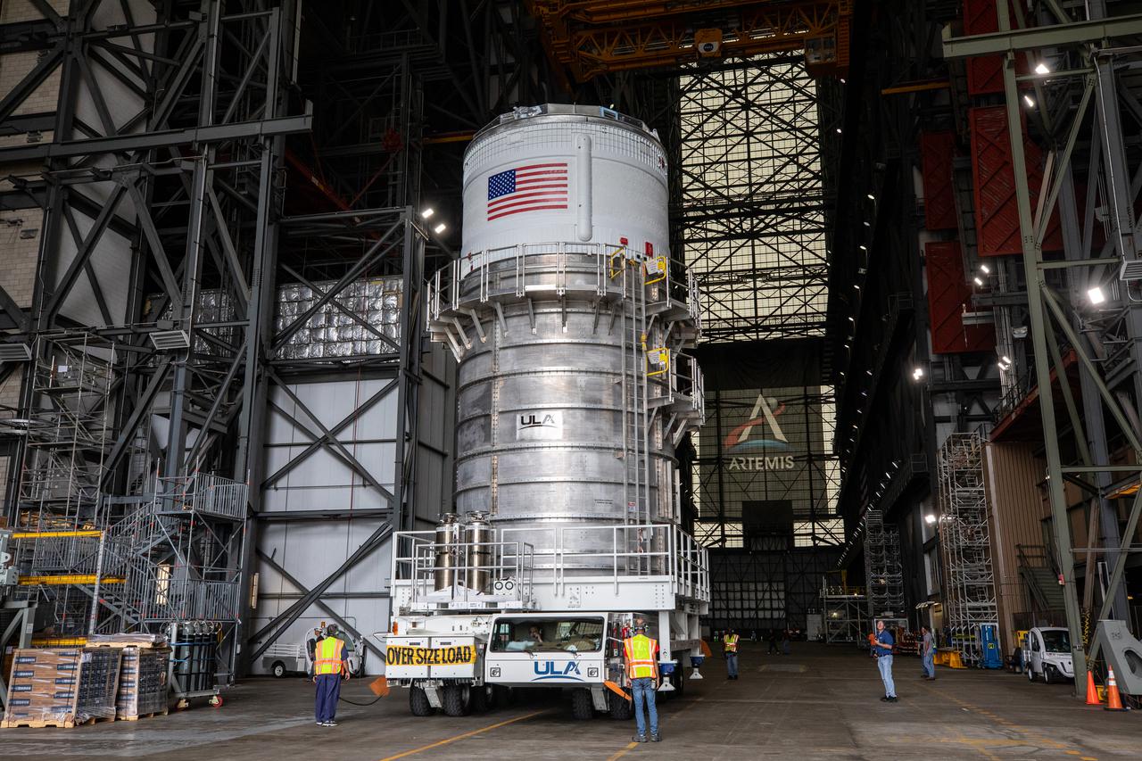
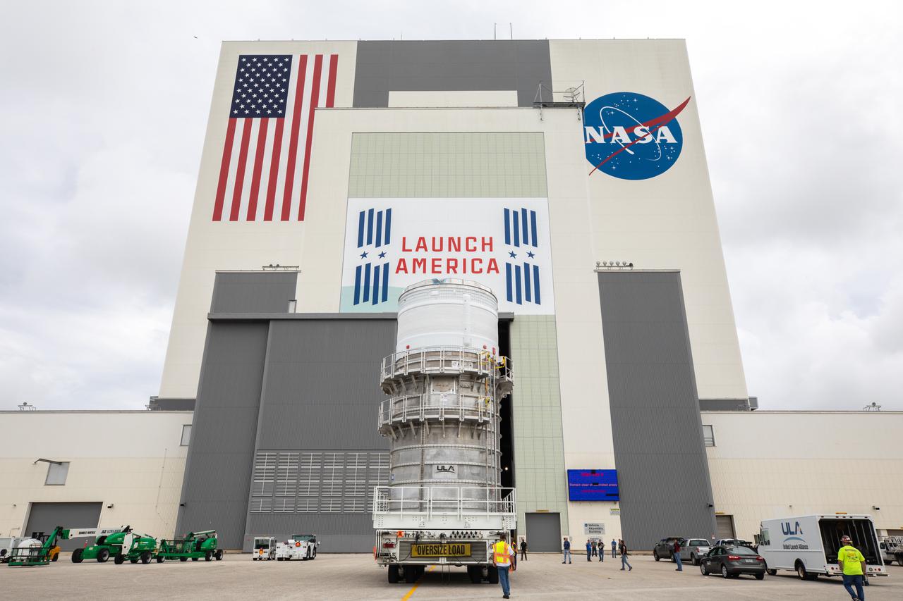
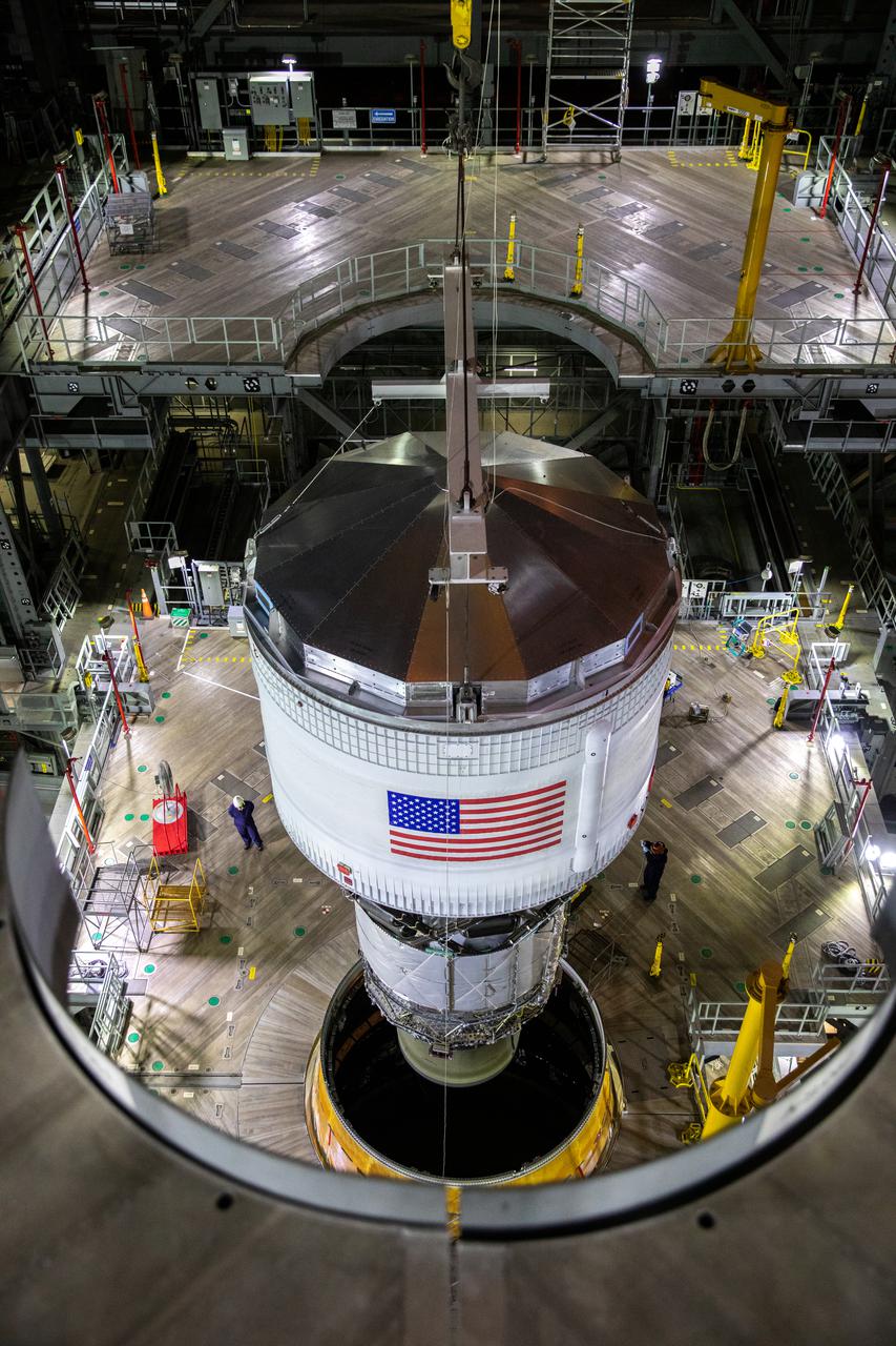
The Space Launch System (SLS) rocket’s interim cryogenic propulsion stage (ICPS) is moved into the transfer aisle of the Vehicle Assembly Building (VAB) by teams with NASA’s Exploration Ground Systems and contractor Jacobs at NASA’s Kennedy Space Center in Florida on Saturday, June 19, 2021. After being fueled and serviced inside the Multi-Payload Processing Facility (MPPF), the ICPS will be hoisted into place atop the SLS core stage while its Aerojet Rocketdyne-built RL-10 engine will be protected inside the launch vehicle stage adapter (LVSA) on the mobile launcher in preparation for the launch of Artemis I. The ICPS will provide Orion spacecraft with the push needed for its flight around the Moon. The first in a series of increasingly complex missions, Artemis I will test SLS and the Orion spacecraft as an integrated system prior to crewed flights in which NASA will land the first woman and person of color on the Moon.
Teams with NASA’s Exploration Ground Systems and contractor Jacobs integrate the interim cryogenic propulsion stage (ICPS) for NASA’s Space Launch System (SLS) rocket with the launch vehicle stage adapter (LVSA) atop the massive SLS core stage in the agency’s Vehicle Assembly Building (VAB) at NASA’s Kennedy Space Center in Florida on July 5, 2021. The ICPS is a liquid oxygen and liquid hydrogen-based system that will fire its RL 10 engine to give the Orion spacecraft the big in-space push needed to fly tens of thousands of miles beyond the Moon. The next component to be stacked on top of ICPS will be the Orion stage adapter, which will connect the ICPS with the spacecraft. Through Artemis, NASA will send the first woman and the first person of color to the lunar surface, as well as establish a sustainable presence on and around the Moon. As the first in an increasingly complex set of missions, Artemis I will test SLS and Orion as an integrated system prior to crewed flights to the Moon.
Teams with NASA’s Exploration Ground Systems and contractor Jacobs integrate the interim cryogenic propulsion stage (ICPS) for NASA’s Space Launch System (SLS) rocket with the launch vehicle stage adapter (LVSA) atop the massive SLS core stage in the agency’s Vehicle Assembly Building (VAB) at NASA’s Kennedy Space Center in Florida on July 5, 2021. The ICPS is a liquid oxygen and liquid hydrogen-based system that will fire its RL 10 engine to give the Orion spacecraft the big in-space push needed to fly tens of thousands of miles beyond the Moon. The next component to be stacked on top of ICPS will be the Orion stage adapter, which will connect the ICPS with the spacecraft. Through Artemis, NASA will send the first woman and the first person of color to the lunar surface, as well as establish a sustainable presence on and around the Moon. As the first in an increasingly complex set of missions, Artemis I will test SLS and Orion as an integrated system prior to crewed flights to the Moon.
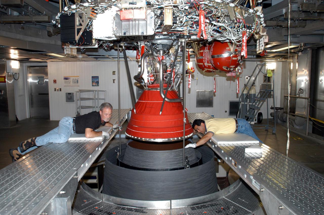
KENNEDY SPACE CENTER, FLA. - At the Delta Operations Center, Jack Reynolds and Leslie Guzman (left and right), with Pratt and Whitney, closely guide the nozzle for the RL-10 engine on the second stage of the Boeing Delta IV rocket. The Delta IV is the launch vehicle for the Geostationary Operational Environmental Satellite (GOES-N), scheduled to launch in April 2005 from Cape Canaveral Air Force Station. GOES-N is a weather satellite for NASA and NOAA (National Oceanic and Atmospheric Administration). The first in a series of three advanced weather satellites including GOES-O and GOES-P, the GOES-N will provide continuous monitoring necessary for intensive data analysis. It will provide a constant vigil for the atmospheric “triggers” of severe weather conditions such as tornadoes, flash floods, hail storms and hurricanes. When these conditions develop, GOES-N will be able to monitor storm development and track their movements.
Teams with NASA’s Exploration Ground Systems and contractor Jacobs integrate the interim cryogenic propulsion stage (ICPS) for NASA’s Space Launch System (SLS) rocket with the launch vehicle stage adapter (LVSA) atop the massive SLS core stage in the agency’s Vehicle Assembly Building (VAB) at NASA’s Kennedy Space Center in Florida on July 5, 2021. The ICPS is a liquid oxygen and liquid hydrogen-based system that will fire its RL 10 engine to give the Orion spacecraft the big in-space push needed to fly tens of thousands of miles beyond the Moon. The next component to be stacked on top of ICPS will be the Orion stage adapter, which will connect the ICPS with the spacecraft. Through Artemis, NASA will send the first woman and the first person of color to the lunar surface, as well as establish a sustainable presence on and around the Moon. As the first in an increasingly complex set of missions, Artemis I will test SLS and Orion as an integrated system prior to crewed flights to the Moon.

Teams with NASA’s Exploration Ground Systems and contractor Jacobs integrate the interim cryogenic propulsion stage (ICPS) for NASA’s Space Launch System (SLS) rocket with the launch vehicle stage adapter (LVSA) atop the massive SLS core stage in the agency’s Vehicle Assembly Building (VAB) at NASA’s Kennedy Space Center in Florida on July 5, 2021. The ICPS is a liquid oxygen and liquid hydrogen-based system that will fire its RL 10 engine to give the Orion spacecraft the big in-space push needed to fly tens of thousands of miles beyond the Moon. The next component to be stacked on top of ICPS will be the Orion stage adapter, which will connect the ICPS with the spacecraft. Through Artemis, NASA will send the first woman and the first person of color to the lunar surface, as well as establish a sustainable presence on and around the Moon. As the first in an increasingly complex set of missions, Artemis I will test SLS and Orion as an integrated system prior to crewed flights to the Moon.
KENNEDY SPACE CENTER, FLA. - At the Delta Operations Center, Jack Reynolds and Leslie Guzman (background) and other workers attach the nozzle for the RL-10 engine to the second stage of the Boeing Delta IV rocket. The Delta IV is the launch vehicle for the Geostationary Operational Environmental Satellite (GOES-N), scheduled to launch in April 2005 from Cape Canaveral Air Force Station. GOES-N is a weather satellite for NASA and NOAA (National Oceanic and Atmospheric Administration). The first in a series of three advanced weather satellites including GOES-O and GOES-P, the GOES-N will provide continuous monitoring necessary for intensive data analysis. It will provide a constant vigil for the atmospheric “triggers” of severe weather conditions such as tornadoes, flash floods, hail storms and hurricanes. When these conditions develop, GOES-N will be able to monitor storm development and track their movements.
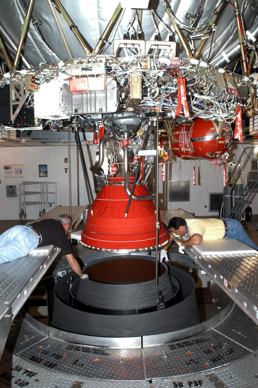
KENNEDY SPACE CENTER, FLA. - At the Delta Operations Center, Jack Reynolds and Leslie Guzman (left and right), with Pratt and Whitney, closely guide the nozzle for the RL-10 engine on the second stage of the Boeing Delta IV rocket. The Delta IV is the launch vehicle for the Geostationary Operational Environmental Satellite (GOES-N), scheduled to launch in April 2005 from Cape Canaveral Air Force Station. GOES-N is a weather satellite for NASA and NOAA (National Oceanic and Atmospheric Administration). The first in a series of three advanced weather satellites including GOES-O and GOES-P, the GOES-N will provide continuous monitoring necessary for intensive data analysis. It will provide a constant vigil for the atmospheric “triggers” of severe weather conditions such as tornadoes, flash floods, hail storms and hurricanes. When these conditions develop, GOES-N will be able to monitor storm development and track their movements.
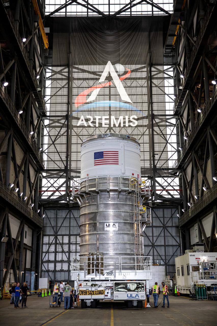
The Space Launch System (SLS) rocket’s interim cryogenic propulsion stage (ICPS) sits in the transfer aisle of the Vehicle Assembly Building (VAB), upon being moved by teams with NASA’s Exploration Ground Systems and contractor Jacobs at NASA’s Kennedy Space Center in Florida on Saturday, June 19, 2021. After being fueled and serviced inside the Multi-Payload Processing Facility (MPPF), the ICPS will be hoisted into place atop the SLS core stage while its Aerojet Rocketdyne-built RL-10 engine will be protected inside the launch vehicle stage adapter (LVSA) on the mobile launcher in preparation for the launch of Artemis I. The ICPS will provide Orion spacecraft with the push needed for its flight around the Moon. The first in a series of increasingly complex missions, Artemis I will test SLS and the Orion spacecraft as an integrated system prior to crewed flights in which NASA will land the first woman and person of color on the Moon.
Teams with NASA’s Exploration Ground Systems and contractor Jacobs integrate the interim cryogenic propulsion stage (ICPS) for NASA’s Space Launch System (SLS) rocket with the launch vehicle stage adapter (LVSA) atop the massive SLS core stage in the agency’s Vehicle Assembly Building (VAB) at NASA’s Kennedy Space Center in Florida on July 5, 2021. The ICPS is a liquid oxygen and liquid hydrogen-based system that will fire its RL 10 engine to give the Orion spacecraft the big in-space push needed to fly tens of thousands of miles beyond the Moon. The next component to be stacked on top of ICPS will be the Orion stage adapter, which will connect the ICPS with the spacecraft. Through Artemis, NASA will send the first woman and the first person of color to the lunar surface, as well as establish a sustainable presence on and around the Moon. As the first in an increasingly complex set of missions, Artemis I will test SLS and Orion as an integrated system prior to crewed flights to the Moon.
Teams with NASA’s Exploration Ground Systems and contractor Jacobs integrate the interim cryogenic propulsion stage (ICPS) for NASA’s Space Launch System (SLS) rocket with the launch vehicle stage adapter (LVSA) atop the massive SLS core stage in the agency’s Vehicle Assembly Building (VAB) at NASA’s Kennedy Space Center in Florida on July 5, 2021. The ICPS is a liquid oxygen and liquid hydrogen-based system that will fire its RL 10 engine to give the Orion spacecraft the big in-space push needed to fly tens of thousands of miles beyond the Moon. The next component to be stacked on top of ICPS will be the Orion stage adapter, which will connect the ICPS with the spacecraft. Through Artemis, NASA will send the first woman and the first person of color to the lunar surface, as well as establish a sustainable presence on and around the Moon. As the first in an increasingly complex set of missions, Artemis I will test SLS and Orion as an integrated system prior to crewed flights to the Moon.
KENNEDY SPACE CENTER, FLA. - At the Delta Operations Center, Jack Reynolds and Leslie Guzman (both at left), with Pratt and Whitney, prepare the nozzle for the RL-10 engine to be attached to the second stage of the Boeing Delta IV rocket. The Delta IV is the launch vehicle for the Geostationary Operational Environmental Satellite (GOES-N), scheduled to launch in April 2005 from Cape Canaveral Air Force Station. GOES-N is a weather satellite for NASA and NOAA (National Oceanic and Atmospheric Administration). The first in a series of three advanced weather satellites including GOES-O and GOES-P, the GOES-N will provide continuous monitoring necessary for intensive data analysis. It will provide a constant vigil for the atmospheric “triggers” of severe weather conditions such as tornadoes, flash floods, hail storms and hurricanes. When these conditions develop, GOES-N will be able to monitor storm development and track their movements.
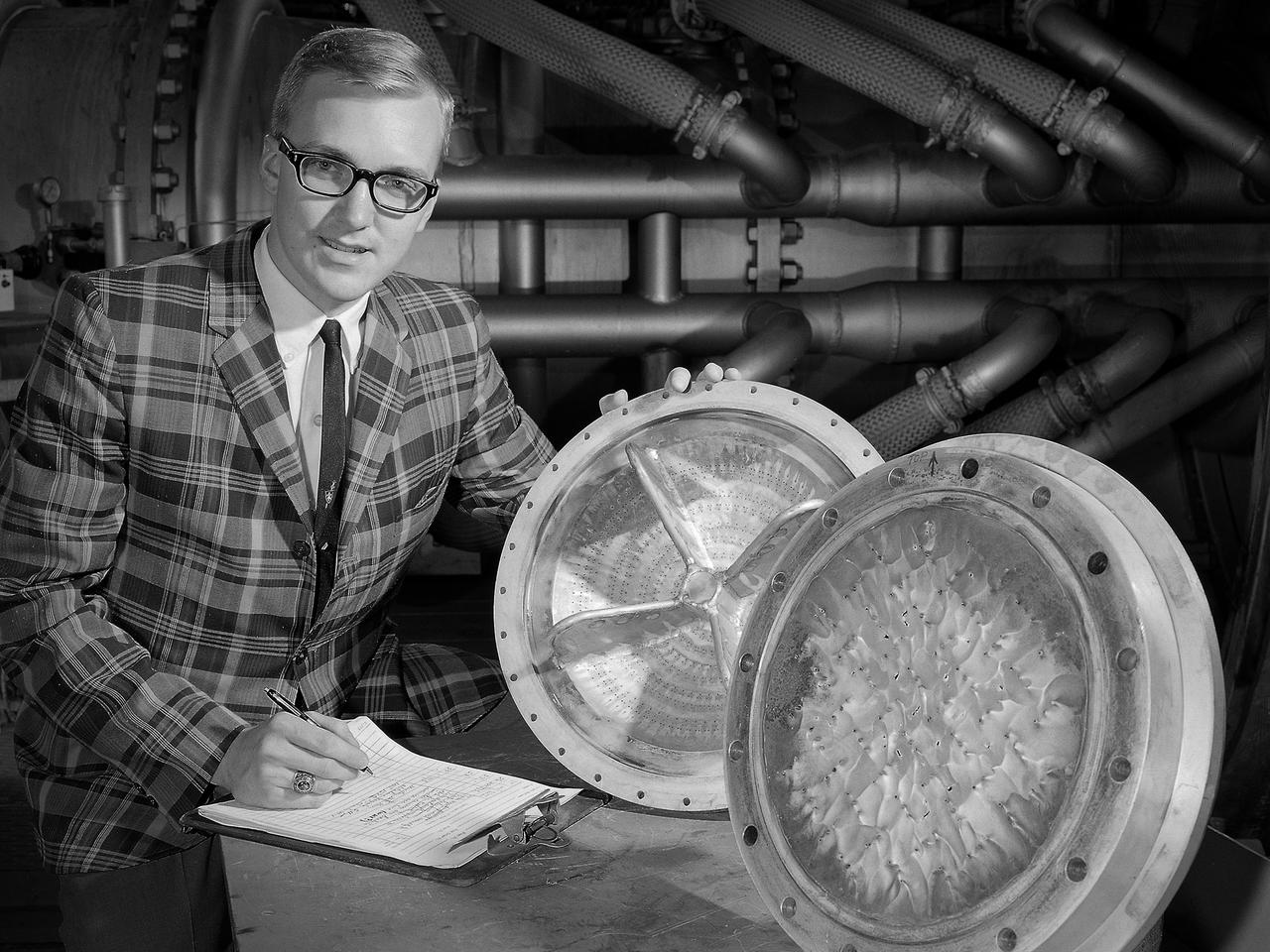
Dan Sokolowski worked as an engineering coop student at the National Aeronautics and Space Administration (NASA) Lewis Research Center from 1962 to 1966 while earning his Mechanical Engineering degree from Purdue. At the time of this photograph Sokolowski had just been hired as a permanent NASA employee in the Chemical Rocket Evaluation Branch of the Chemical Rocket Division. He had also just won a regional American Institute of Aeronautics and Astronautics competition for his paper on high and low-frequency combustion instability. The resolution of the low-frequency combustion instability, or chugging, in liquid hydrogen rocket systems was one of Lewis’ more significant feats of the early 1960s. In most rocket engine combustion chambers, the pressure, temperature, and flows are in constant flux. The engine is considered to be operating normally if the fluctuations remain random and within certain limits. Lewis researchers used high-speed photography to study and define Pratt and Whitney’s RL-10’s combustion instability by throttling the engine under the simulated flight conditions. They found that the injection of a small stream of helium gas into the liquid-oxygen tank immediately stabilized the system. Sokolowski’s later work focused on combustion in airbreathing engines. In 1983 was named Manager of a multidisciplinary program aimed at improving durability of combustor and turbine components. After 39 years Sokolowski retired from NASA in September 2002.
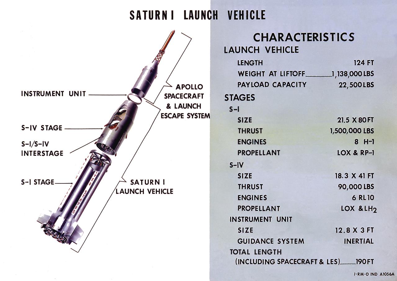
A cutaway illustration of Saturn I launch vehicle characteristics: The Saturn I, first of the Saturn launch vehicles' family, is a two-stage vehicle with a low-earth-orbit payload capability of approximately 25,000 pounds. The research and development program was plarned in two phases or blocks; one for first stage development (Block I) and the second for first and second stage development (Block II). The S-I (first) stage consisted of a cluster of nine propellant tanks and eight H-1 engines built by Rocketdyne, yeilding a total thrust of 1,500,000 pounds. The second stage identified as S-IV, was designed as a single cylinder with a common bulkhead separating the liquid oxygen from the liquid hydrogen. Propulsion was provided by six RL-10 engines built by Pratt Whitney, capable of producing a combined thrust of 90,000 pounds. Of the 10 Saturn I's planned, the first eight were designed and built at the Marshall Space Flight Center. The remaining two were built by the Chrysler Corporation.
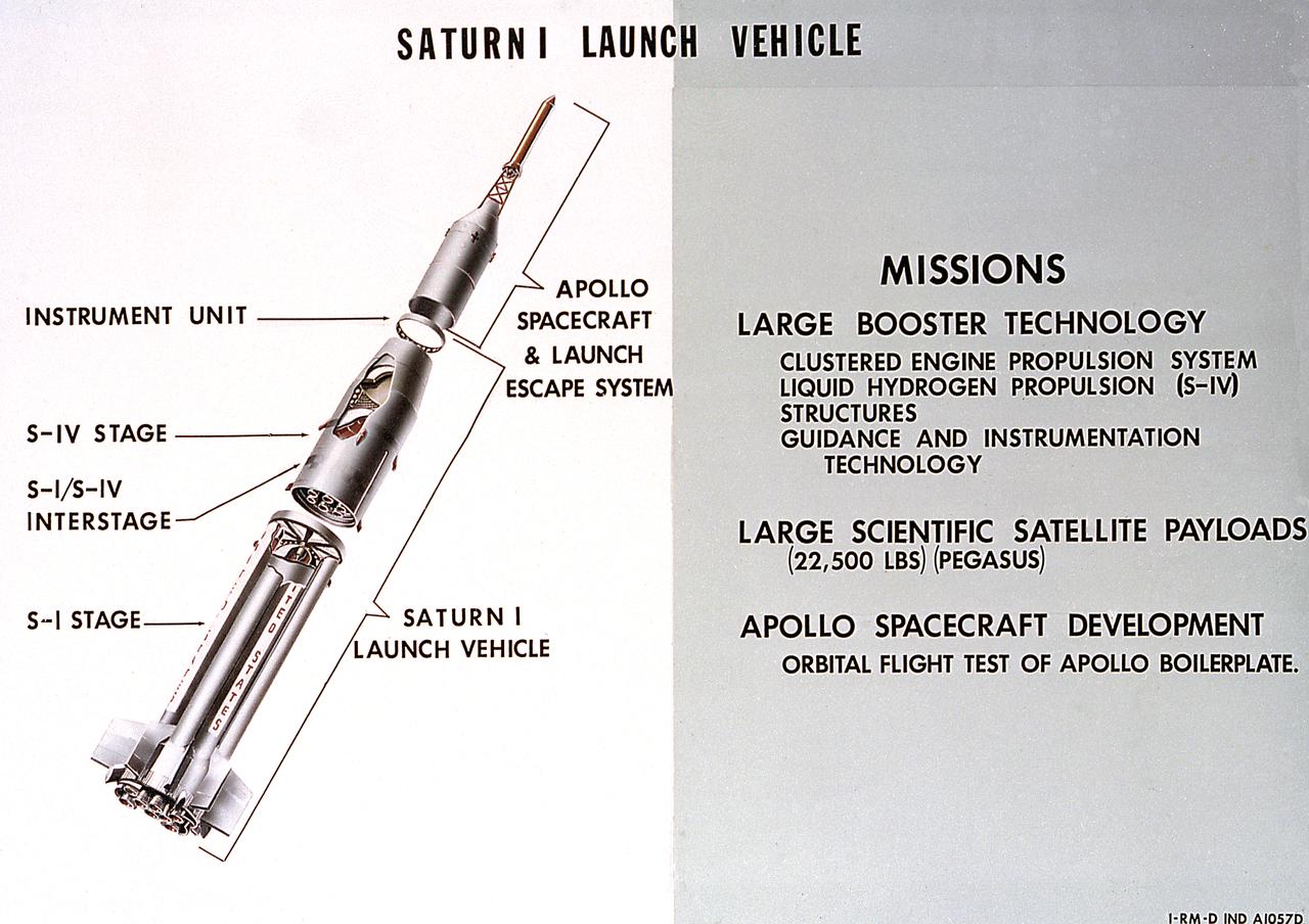
A cutaway illustration of Saturn 1 launch vehicle mission. The Saturn I, first of the Saturn launch vehicles' family, is a two-stage vehicle with a low-earth-orbit payload capability of approximately 25,000 pounds. The research and development program was plarned in two phases or blocks; one for first stage development (Block I) and the second for first and second stage development (Block II). The S-I (first) stage consisted of a cluster of nine propellant tanks and eight H-1 engines built by Rocketdyne, yeilding a total thrust of 1,500,000 pounds. The second stage of Saturn I, identified as S-IV, was designed as a single cylinder with a common bulkhead separating the liquid oxygen from the liquid hydrogen. Propulsion was provided by six RL-10 engines built by Pratt Whitney, capable of producing a combined thrust of 90,000 pounds. Of the 10 Saturn I's planned, the first eight were designed and built at the Marshall Space Flight Center. The remaining two were built by the Chrysler Corporation.
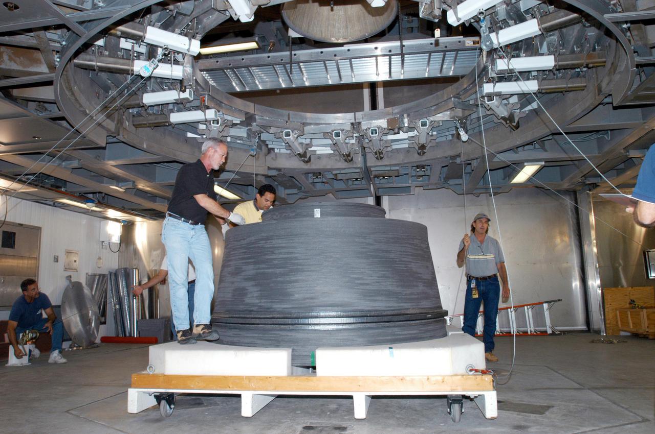
Bill Harrison and Bud Meilander check the setup of an Apollo Contour rocket nozzle in the Propulsion Systems Laboratory at the National Aeronautics and Space Administration (NASA) Lewis Research Center. The Propulsion Systems Laboratory contained two 14-foot diameter test chambers that could simulate conditions found at very high altitudes. The facility was used in the 1960s to study complex rocket engines such as the Pratt and Whitney RL-10 and rocket components such as the Apollo Contour nozzle, seen here. Meilander oversaw the facility’s mechanics and the installation of test articles into the chambers. Harrison was head of the Supersonic Tunnels Branch in the Test Installations Division. Researchers sought to determine the impulse value of the storable propellant mix, classify and improve the internal engine performance, and compare the results with analytical tools. A special setup was installed in the chamber that included a device to measure the thrust load and a calibration stand. Both cylindrical and conical combustion chambers were examined with the conical large area ratio nozzles. In addition, two contour nozzles were tested, one based on the Apollo Service Propulsion System and the other on the Air Force’s Titan transtage engine. Three types of injectors were investigated, including a Lewis-designed model that produced 98-percent efficiency. It was determined that combustion instability did not affect the nozzle performance. Although much valuable information was obtained during the tests, attempts to improve the engine performance were not successful.
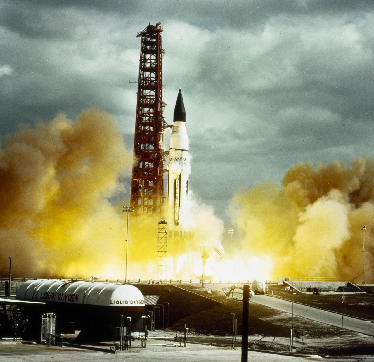
Developed at MSFC under the direction of Dr. Wernher von Braun, the SA-5 incorporated a Saturn I, Block II engine. Launched on January 29, 1964, SA-5 was the first two stage (Block II) Saturn with orbital capability and performed the first test of Instrument Unit and successful stage separation. Block II vehicles had two live stages, and were basically in the two-stage configuration of the Saturn I vehicle. There were marked changes between the Block I and II versions. The Block II S-I stage had eight fins added for greater aerodynamic stability in the lower atmosphere. All Block II H-1 engines had a thrust of 188,000 pounds each for a combined thrust over 1,500,000 pounds. The Block II second stage (S-IV) had six RL-10 hydrogen-oxygen engines, each producing a thrust of 15,000 pounds for a total combined thrust of 90,000 pounds. A motion picture camera capsule loated on stage I was successful recovered.
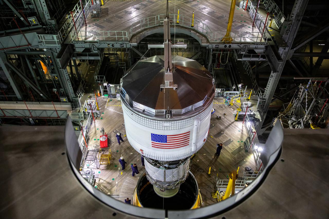
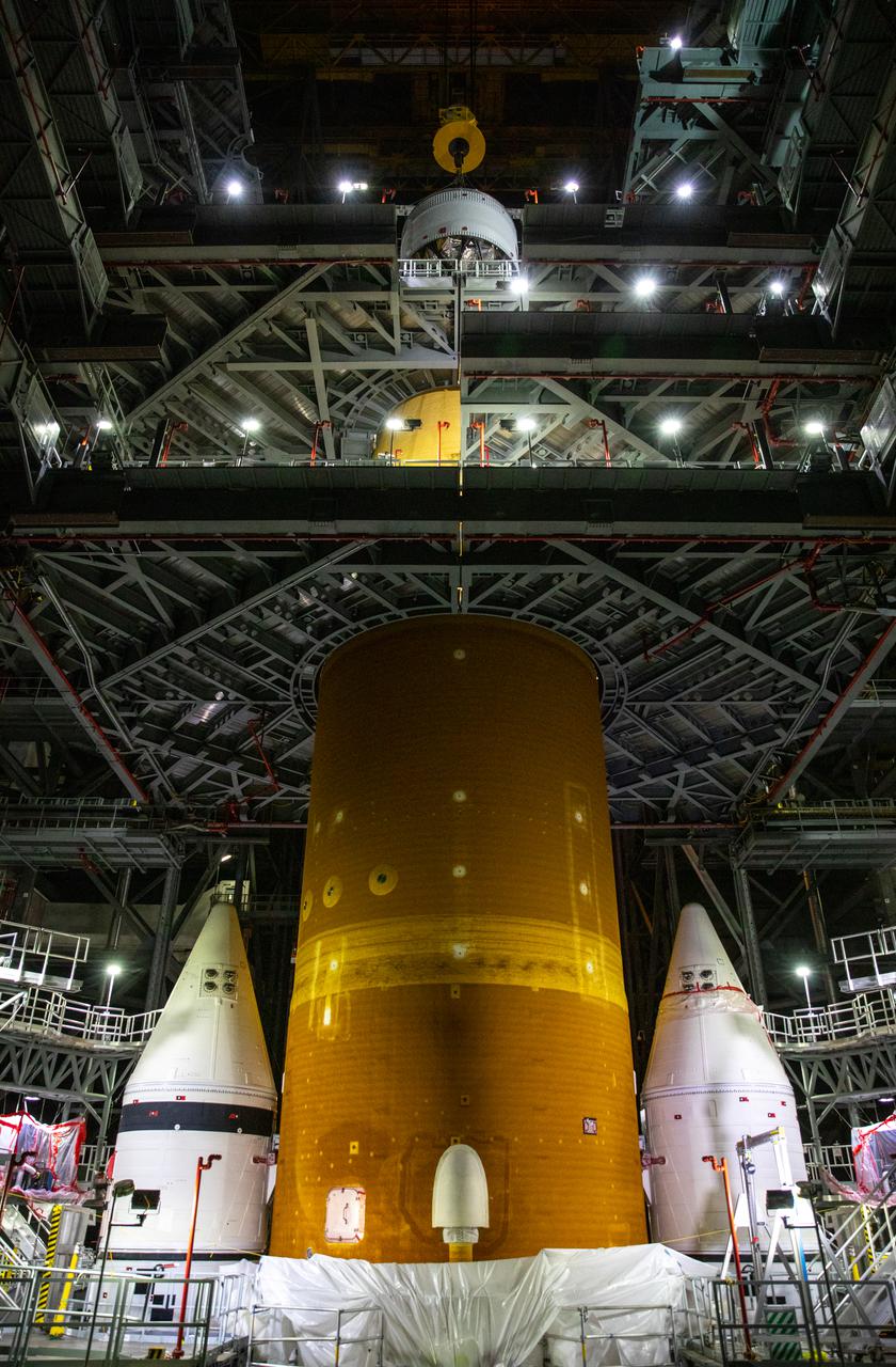
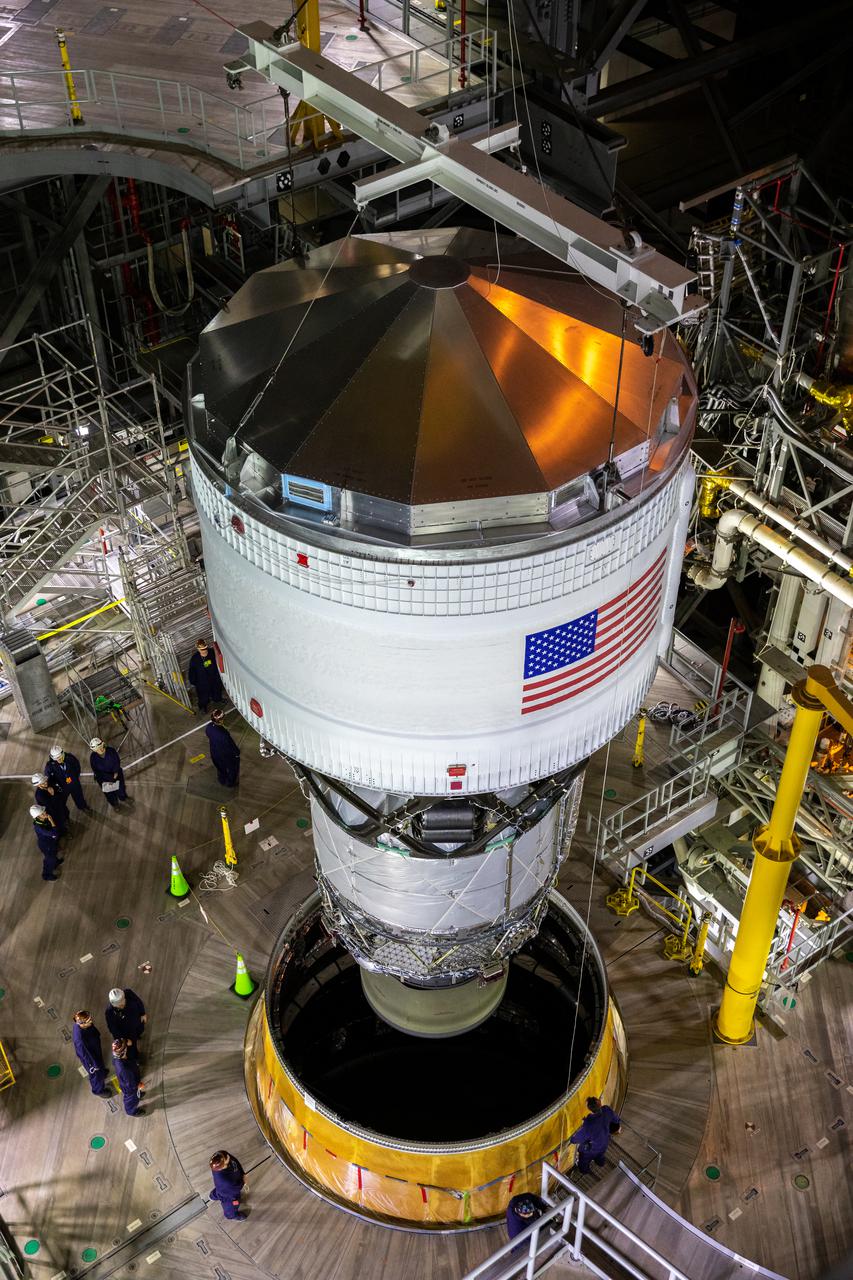
Teams with NASA’s Exploration Ground Systems and contractor Jacobs integrated the interim cryogenic propulsion stage (ICPS) for NASA’s Space Launch System (SLS) rocket with the launch vehicle stage adapter (LVSA) atop the massive SLS core stage on the mobile launcher inside the agency’s Vehicle Assembly Building (VAB) at NASA’s Kennedy Space Center in Florida on July 5, 2021. The ICPS’s RL 10 engine is housed inside the launch vehicle stage adapter, which will protect the engine during launch. The ICPS is a liquid oxygen and liquid hydrogen-based system that will give the Orion spacecraft the big in-space push needed to fly tens of thousands of miles beyond the Moon. The next component to be stacked on top of ICPS will be the Orion stage adapter, which will connect the ICPS with the spacecraft. Through Artemis, NASA will send the first woman and the first person of color to the lunar surface, as well as establish a sustainable presence on and around the Moon. As the first in an increasingly complex set of missions, Artemis I will test SLS and Orion as an integrated system prior to crewed flights to the Moon.
Teams with NASA’s Exploration Ground Systems and contractor Jacobs integrated the interim cryogenic propulsion stage (ICPS) for NASA’s Space Launch System (SLS) rocket with the launch vehicle stage adapter (LVSA) atop the massive SLS core stage on the mobile launcher inside the agency’s Vehicle Assembly Building (VAB) at NASA’s Kennedy Space Center in Florida on July 5, 2021. The ICPS’s RL 10 engine is housed inside the launch vehicle stage adapter, which will protect the engine during launch. The ICPS is a liquid oxygen and liquid hydrogen-based system that will give the Orion spacecraft the big in-space push needed to fly tens of thousands of miles beyond the Moon. The next component to be stacked on top of ICPS will be the Orion stage adapter, which will connect the ICPS with the spacecraft. Through Artemis, NASA will send the first woman and the first person of color to the lunar surface, as well as establish a sustainable presence on and around the Moon. As the first in an increasingly complex set of missions, Artemis I will test SLS and Orion as an integrated system prior to crewed flights to the Moon.
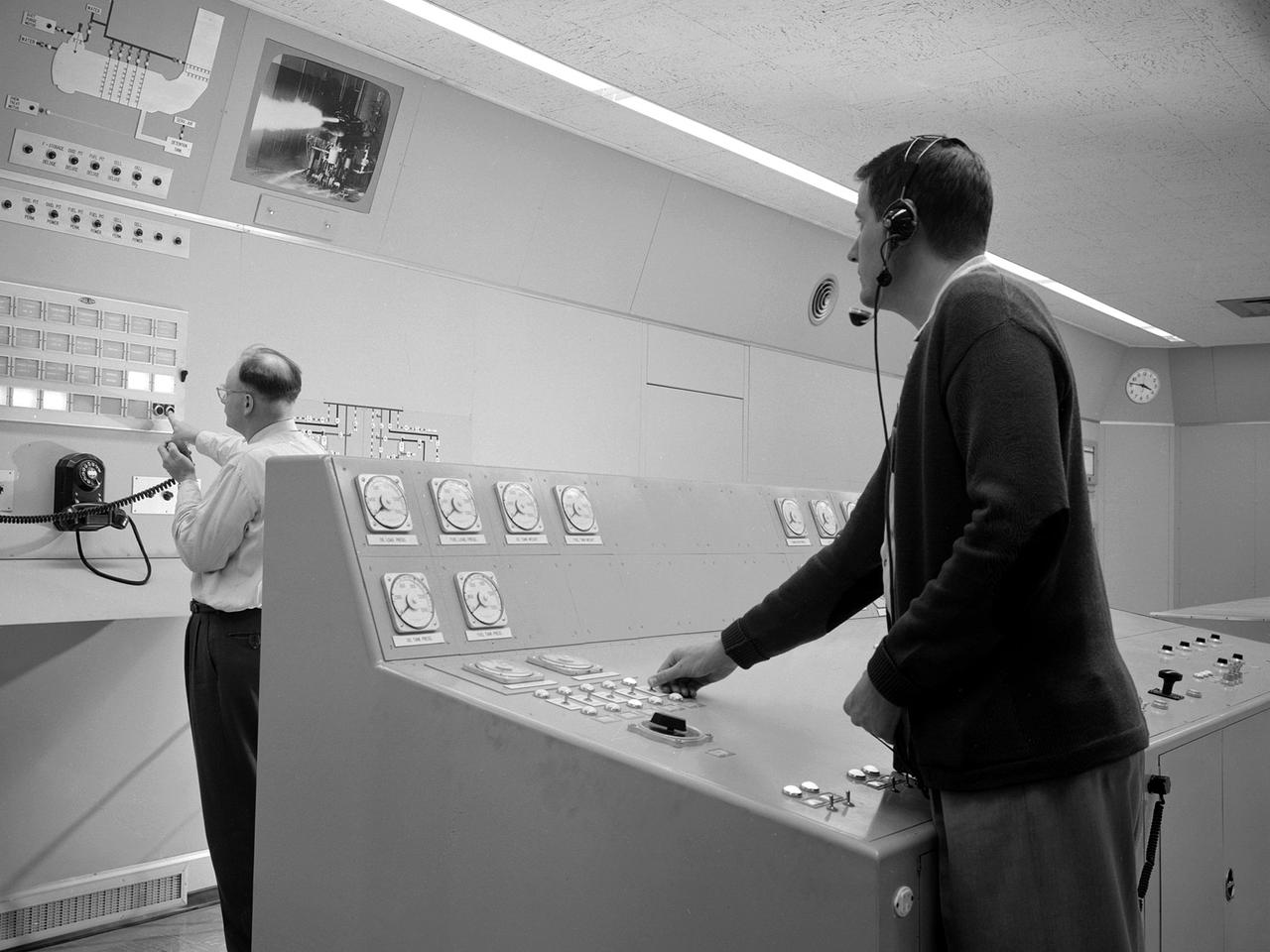
Test engineers monitor an engine firing from the control room of the Rocket Engine Test Facility at the National Advisory Committee for Aeronautics (NACA) Lewis Flight Propulsion Laboratory. The Rocket Engine Test Facility, built in the early 1950s, had a rocket stand designed to evaluate high-energy propellants and rocket engine designs. The facility was used to study numerous different types of rocket engines including the Pratt and Whitney RL-10 engine for the Centaur rocket and Rocketdyne’s F-1 and J-2 engines for the Saturn rockets. The Rocket Engine Test Facility was built in a ravine at the far end of the laboratory because of its use of the dangerous propellants such as liquid hydrogen and liquid fluorine. The control room was located in a building 1,600 feet north of the test stand to protect the engineers running the tests. The main control and instrument consoles were centrally located in the control room and surrounded by boards controlling and monitoring the major valves, pumps, motors, and actuators. A camera system at the test stand allowed the operators to view the tests, but the researchers were reliant on data recording equipment, sensors, and other devices to provide test data. The facility’s control room was upgraded several times over the years. Programmable logic controllers replaced the electro-mechanical control devices. The new controllers were programed to operate the valves and actuators controlling the fuel, oxidant, and ignition sequence according to a predetermined time schedule.
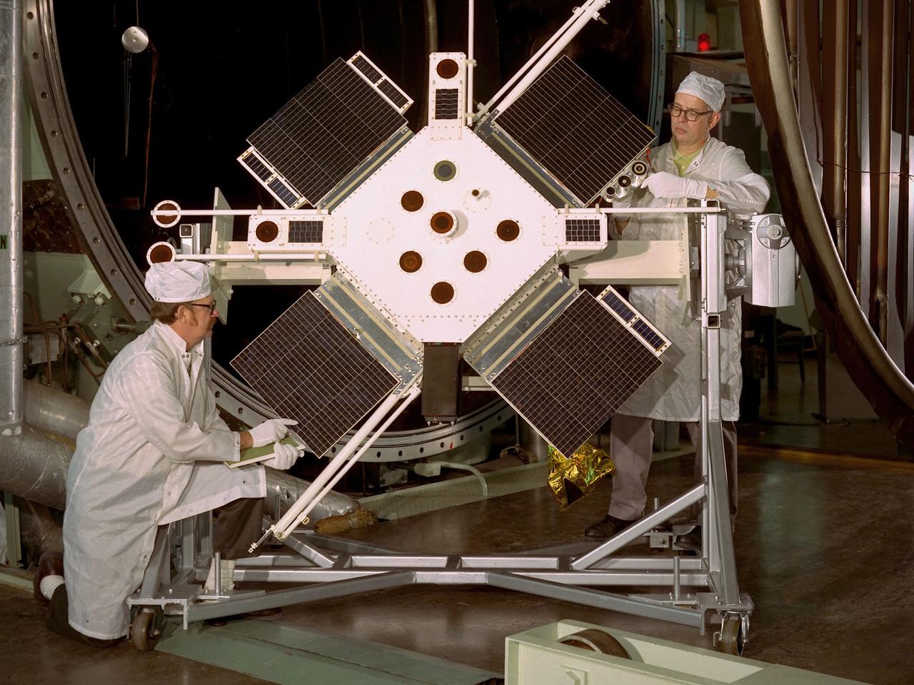
Researchers examine the Space Plasma-High Voltage Interaction Experiment (SPHINX) satellite in the Electric Propulsion Laboratory at the National Aeronautics and Space Administration (NASA) Lewis Research Center. Lewis’ Spacecraft Technology Division designed SPHINX to study the electrical interaction of its experimental surfaces with space plasma. They sought to determine if higher orbits would improve the transmission quality of communications satellites. Robert Lovell, the Project Manager, oversaw vibrational and plasma simulation testing of the satellite in the Electric Propulsion Laboratory, seen here. SPHINX was an add-on payload for the first Titan/Centaur proof launch in early 1974. Lewis successfully managed the Centaur Program since 1962, but this would be the first Centaur launch with a Titan booster. Since the proof test did not have a scheduled payload, the Lewis-designed SPHINX received a free ride. The February 11, 1974 launch, however, proved to be one of the Launch Vehicle Division’s lowest days. Twelve minutes after the vehicle departed the launch pad, the booster and Centaur separated as designed, but Centaur’s two RL-10 engines failed to ignite. The launch pad safety officer destroyed the vehicle, and SPHINX never made it into orbit. Overall Centaur has an excellent success rate, but the failed SPHINX launch attempt caused deep disappointment across the center.