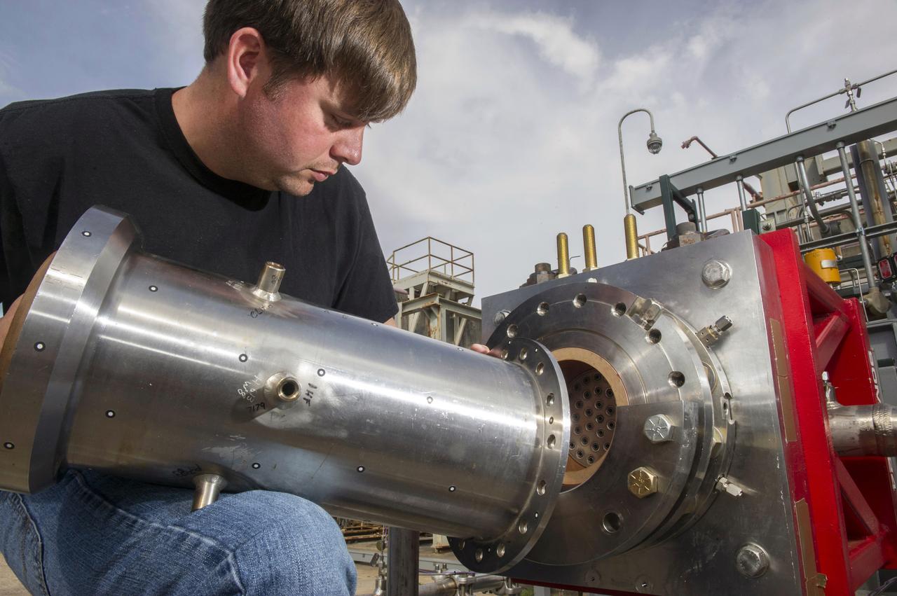
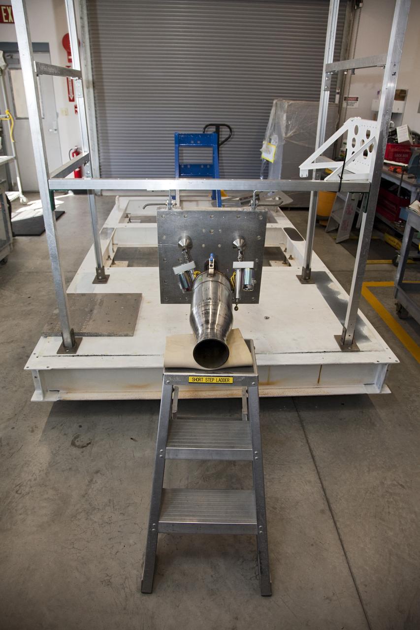
1. ENGINEERS AND TECHNICIANS PREPARE FOR AN UPCOMING HOT-FIRE TEST OF A ROCKET INJECTOR MANUFACTURED USING ADDITIVE MANUFACTURING, OR 3-D PRINTING…RANDALL MCALLISTER, INFOPRO TECHNICIAN, FITS NOZZLE TO ROCKET INJECTOR
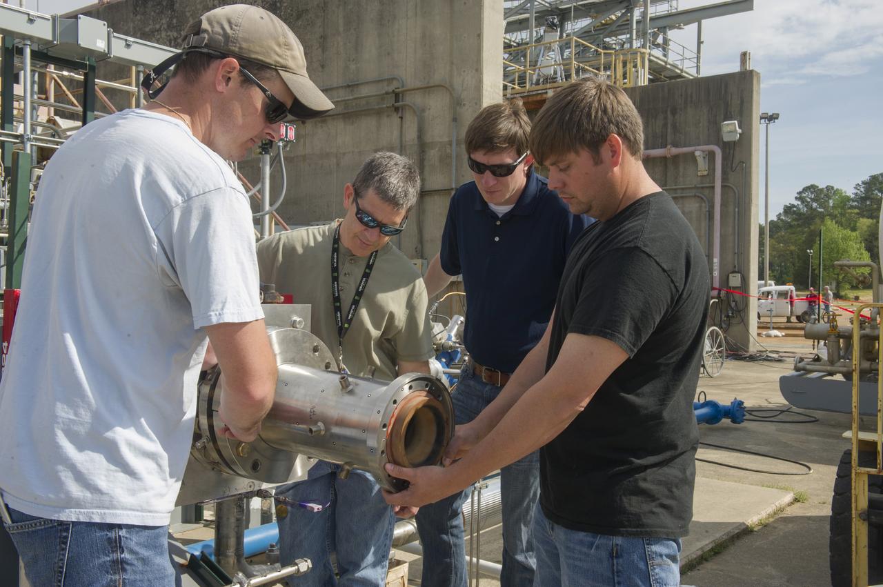
2. ENGINEERS AND TECHNICIANS PREPARE FOR AN UPCOMING HOT-FIRE TEST OF A ROCKET INJECTOR MANUFACTURED USING ADDITIVE MANUFACTURING, OR 3-D PRINTING…(L TO R) WILLIE PARKER, INFOPRO TECHNICIAN, BRAD BULLARD, NASA, NICK CASE, NASA, AND RANDALL MCALLISTER, INFOPRO TECHNICIAN
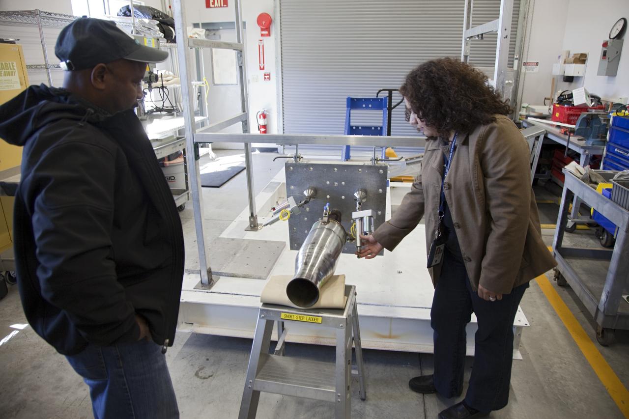
CAPE CANAVERAL, Fla. -- At the Neo Liquid Propellant Testbed inside a facility near Kennedy Space Center’s Shuttle Landing Facility in Florida, engineers and Rocket University project leads Kyle Dixon, left, and Evelyn Orozco-Smith check the buildup of the Neo test fixture and an Injector 71 engine that uses super-cooled propellants. NASA engineers are working on the design and assembly of the Neo Liquid Propellant Testbed as part of the Engineering Directorate’s Rocket University training program. Photo credit: NASA/Frankie Martin
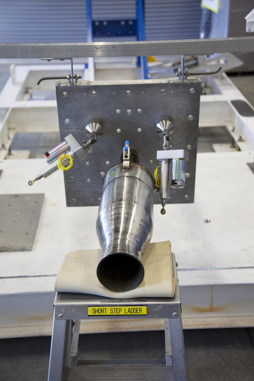
CAPE CANAVERAL, Fla. -- At the Neo Liquid Propellant Testbed inside a facility near Kennedy Space Center’s Shuttle Landing Facility in Florida, engineers are working on the buildup of the Neo test fixture and an Injector 71 engine that uses super-cooled propellants. NASA engineers are working on the design and assembly of the Neo Liquid Propellant Testbed as part of the Engineering Directorate’s Rocket University training program. Photo credit: NASA/Frankie Martin
CAPE CANAVERAL, Fla. -- At the Neo Liquid Propellant Testbed inside a facility near Kennedy Space Center’s Shuttle Landing Facility in Florida, engineers are working on the buildup of the Neo test fixture and an Injector 71 engine that uses super-cooled propellants. NASA engineers are working on the design and assembly of the Neo Liquid Propellant Testbed as part of the Engineering Directorate’s Rocket University training program. Photo credit: NASA/Frankie Martin
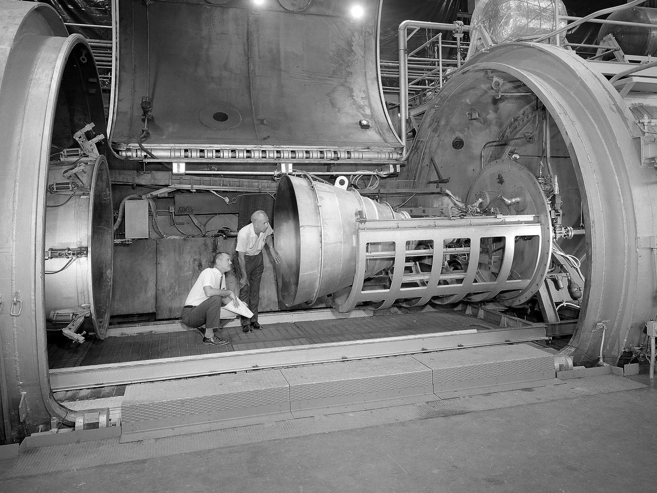
Bill Harrison and Bud Meilander check the setup of an Apollo Contour rocket nozzle in the Propulsion Systems Laboratory at the National Aeronautics and Space Administration (NASA) Lewis Research Center. The Propulsion Systems Laboratory contained two 14-foot diameter test chambers that could simulate conditions found at very high altitudes. The facility was used in the 1960s to study complex rocket engines such as the Pratt and Whitney RL-10 and rocket components such as the Apollo Contour nozzle, seen here. Meilander oversaw the facility’s mechanics and the installation of test articles into the chambers. Harrison was head of the Supersonic Tunnels Branch in the Test Installations Division. Researchers sought to determine the impulse value of the storable propellant mix, classify and improve the internal engine performance, and compare the results with analytical tools. A special setup was installed in the chamber that included a device to measure the thrust load and a calibration stand. Both cylindrical and conical combustion chambers were examined with the conical large area ratio nozzles. In addition, two contour nozzles were tested, one based on the Apollo Service Propulsion System and the other on the Air Force’s Titan transtage engine. Three types of injectors were investigated, including a Lewis-designed model that produced 98-percent efficiency. It was determined that combustion instability did not affect the nozzle performance. Although much valuable information was obtained during the tests, attempts to improve the engine performance were not successful.

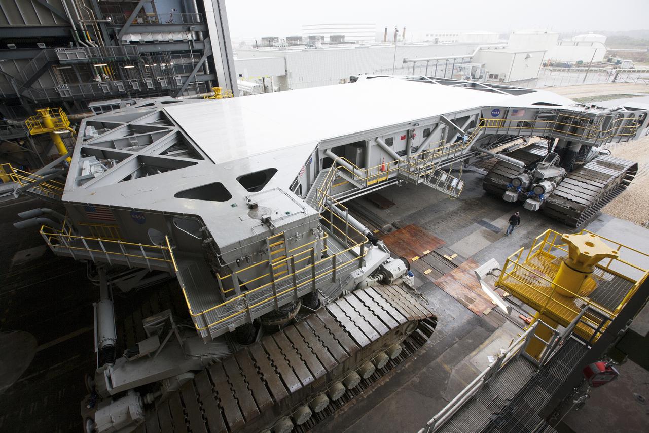
CAPE CANAVERAL, Fla. – Crawler-transporter 2, or CT-2, travels along the crawlerway toward the Vehicle Assembly Building at NASA’s Kennedy Space Center in Florida. The Ground Systems Development and Operations Program completed a roller bearing assembly test on CT-2 truck sections A and C. The left- and right-hand steering was tested in both directions. The temperature of the roller assemblies was monitored and recorded as it traveled along the crawlerway. Engineers and technicians performed visual inspections of the roller bearing pumps, valves and lines to ensure that the grease injectors worked properly and provided the required flow of grease to the new roller assemblies. Work continues in high bay 2 to upgrade CT-2. The modifications are designed to ensure CT-2’s ability to transport launch vehicles currently in development, such as the agency’s Space Launch System, to the launch pad. The Ground Systems Development and Operations Program office at Kennedy is overseeing the upgrades. For more than 45 years the crawler-transporters were used to transport the mobile launcher platform and the Apollo-Saturn V rockets and, later, space shuttles to Launch Pads 39A and B. For more information, visit: http:__www.nasa.gov_exploration_systems_ground_crawler-transporter. Photo credit: NASA_Kim Shiflett
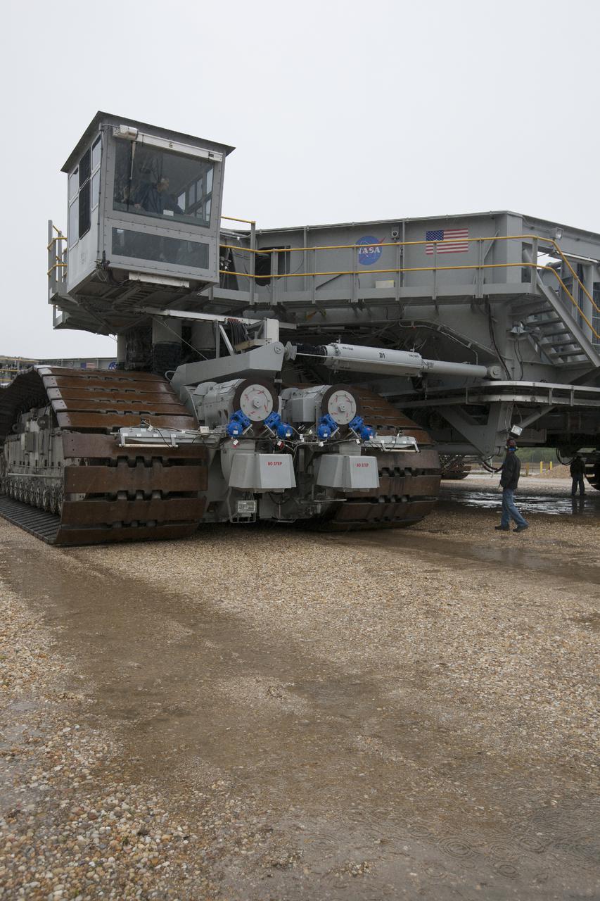
CAPE CANAVERAL, Fla. – A technician in the cab of crawler-transporter 2, or CT-2, drives along the crawlerway toward the Vehicle Assembly Building at NASA’s Kennedy Space Center in Florida. The Ground Systems Development and Operations Program completed a roller bearing assembly test on CT-2 truck sections A and C. The left- and right-hand steering was tested in both directions. The temperature of the roller assemblies was monitored and recorded. Engineers and technicians performed visual inspections of the roller bearing pumps, valves and lines to ensure that the grease injectors worked properly and provided the required flow of grease to the new roller assemblies. Work continues in high bay 2 to upgrade CT-2. The modifications are designed to ensure CT-2’s ability to transport launch vehicles currently in development, such as the agency’s Space Launch System, to the launch pad. The Ground Systems Development and Operations Program office at Kennedy is overseeing the upgrades. For more than 45 years the crawler-transporters were used to transport the mobile launcher platform and the Apollo-Saturn V rockets and, later, space shuttles to Launch Pads 39A and B. For more information, visit: http:__www.nasa.gov_exploration_systems_ground_crawler-transporter. Photo credit: NASA_Kim Shiflett
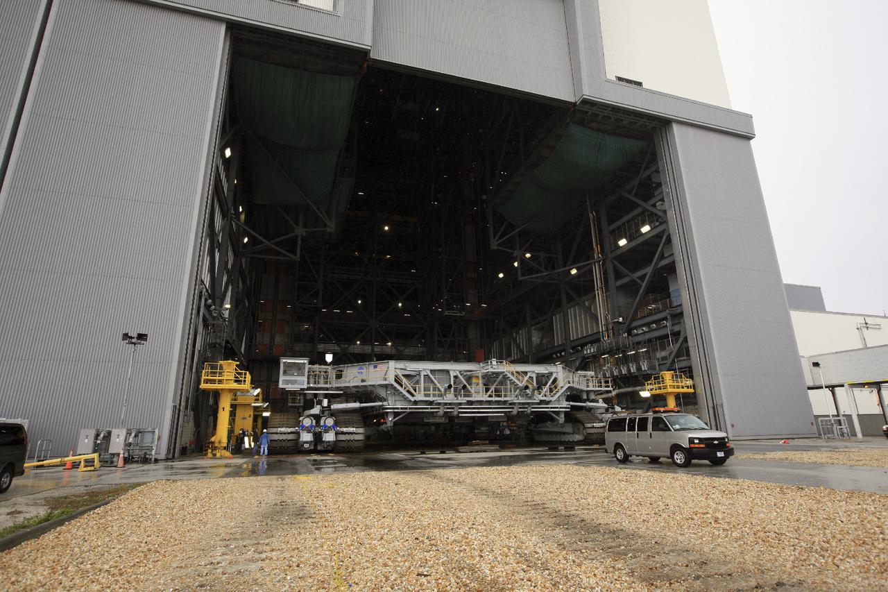
CAPE CANAVERAL, Fla. – Crawler-transporter 2, or CT-2, slowly enters the Vehicle Assembly Building at NASA’s Kennedy Space Center in Florida. The Ground Systems Development and Operations Program completed a roller bearing assembly test on CT-2 truck sections A and C. The left- and right-hand steering was tested in both directions. The temperature of the roller assemblies was monitored and recorded as it traveled along the crawlerway. Engineers and technicians performed visual inspections of the roller bearing pumps, valves and lines to ensure that the grease injectors worked properly and provided the required flow of grease to the new roller assemblies. Work continues in high bay 2 to upgrade CT-2. The modifications are designed to ensure CT-2’s ability to transport launch vehicles currently in development, such as the agency’s Space Launch System, to the launch pad. The Ground Systems Development and Operations Program office at Kennedy is overseeing the upgrades. For more than 45 years the crawler-transporters were used to transport the mobile launcher platform and the Apollo-Saturn V rockets and, later, space shuttles to Launch Pads 39A and B. For more information, visit: http:__www.nasa.gov_exploration_systems_ground_crawler-transporter. Photo credit: NASA_Kim Shiflett
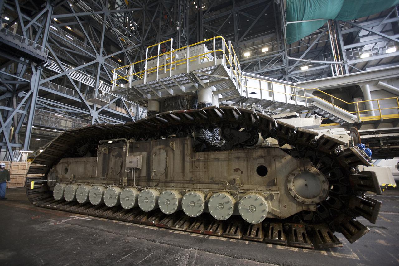
CAPE CANAVERAL, Fla. – Crawler-transporter 2, or CT-2, enters the Vehicle Assembly Building at NASA’s Kennedy Space Center in Florida. Visible are the new roller bearing assemblies that were installed on one side of the crawler. The Ground Systems Development and Operations Program completed a roller bearing assembly test on CT-2 truck sections A and C. The left- and right-hand steering was tested in both directions. The temperature of the roller assemblies was monitored and recorded as it traveled along the crawlerway. Engineers and technicians performed visual inspections of the roller bearing pumps, valves and lines to ensure that the grease injectors worked properly and provided the required flow of grease to the new roller assemblies. Work continues in high bay 2 to upgrade CT-2. The modifications are designed to ensure CT-2’s ability to transport launch vehicles currently in development, such as the agency’s Space Launch System, to the launch pad. The Ground Systems Development and Operations Program office at Kennedy is overseeing the upgrades. For more than 45 years the crawler-transporters were used to transport the mobile launcher platform and the Apollo-Saturn V rockets and, later, space shuttles to Launch Pads 39A and B. For more information, visit: http:__www.nasa.gov_exploration_systems_ground_crawler-transporter. Photo credit: NASA_Kim Shiflett
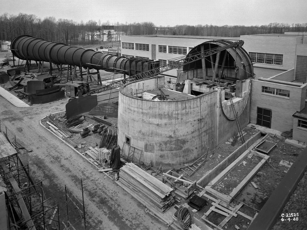
The 8- by 6-Foot Supersonic Wind Tunnel at the National Advisory Committee for Aeronautics (NACA) Lewis Flight Propulsion Laboratory was the nation’s largest supersonic facility when it began operation in April 1949. The emergence of new propulsion technologies such as turbojets, ramjets, and rockets during World War II forced the NACA and the aircraft industry to develop new research tools. In late 1945 the NACA began design work for new large supersonic wind tunnels at its three laboratories. The result was the 4- by 4-Foot Supersonic Wind Tunnel at Langley Memorial Aeronautical Laboratory, 6- by 6-foot supersonic wind tunnel at Ames Aeronautical Laboratory, and the largest facility, the 8- by 6-Foot Supersonic Wind Tunnel in Cleveland. The two former tunnels were to study aerodynamics, while the 8- by 6 facility was designed for supersonic propulsion. The 8- by 6-Foot Supersonic Wind Tunnel was used to study propulsion systems, including inlets and exit nozzles, combustion fuel injectors, flame holders, exit nozzles, and controls on ramjet and turbojet engines. Flexible sidewalls alter the tunnel’s nozzle shape to vary the Mach number during operation. A seven-stage axial compressor, driven by three electric motors that yield a total of 87,000 horsepower, generates air speeds from Mach 0.36 to 2.0. A section of the tunnel is seen being erected in this photograph.
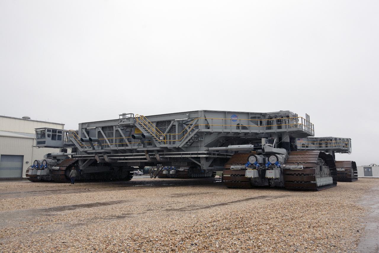
CAPE CANAVERAL, Fla. – Crawler-transporter 2, or CT-2, travels along the crawlerway toward the Vehicle Assembly Building at NASA’s Kennedy Space Center in Florida. The Ground Systems Development and Operations Program completed a roller bearing assembly test on CT-2 truck sections A and C. The left- and right-hand steering was tested in both directions. The temperature of the roller assemblies was monitored and recorded. Engineers and technicians performed visual inspections of the roller bearing pumps, valves and lines to ensure that the grease injectors worked properly and provided the required flow of grease to the new roller assemblies. Work continues in high bay 2 to upgrade CT-2. The modifications are designed to ensure CT-2’s ability to transport launch vehicles currently in development, such as the agency’s Space Launch System, to the launch pad. The Ground Systems Development and Operations Program office at Kennedy is overseeing the upgrades. For more than 45 years the crawler-transporters were used to transport the mobile launcher platform and the Apollo-Saturn V rockets and, later, space shuttles to Launch Pads 39A and B. For more information, visit: http:__www.nasa.gov_exploration_systems_ground_crawler-transporter. Photo credit: NASA_Kim Shiflett
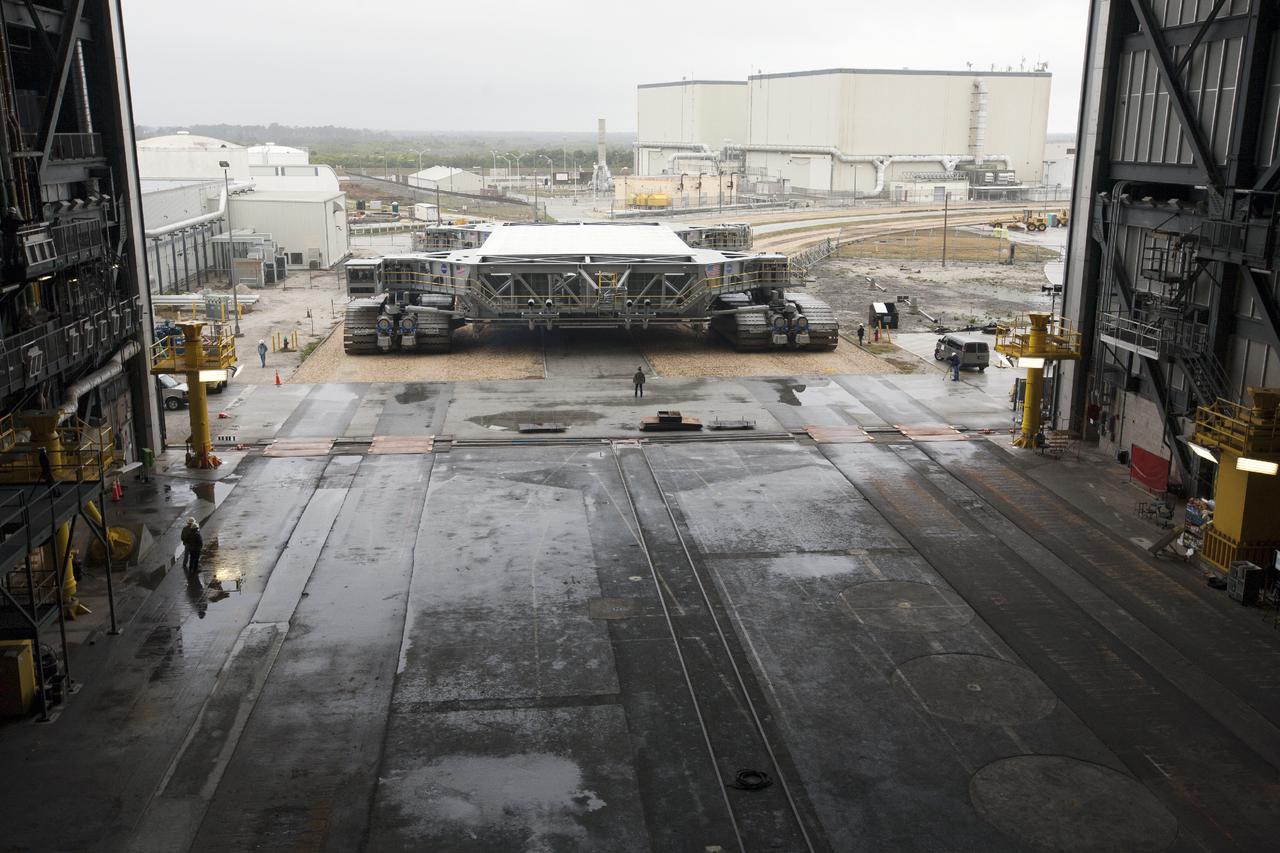
CAPE CANAVERAL, Fla. – Crawler-transporter 2, or CT-2, nears the entrance to the Vehicle Assembly Building at NASA’s Kennedy Space Center in Florida. The Ground Systems Development and Operations Program completed a roller bearing assembly test on CT-2 truck sections A and C. The left- and right-hand steering was tested in both directions. The temperature of the roller assemblies was monitored and recorded as it traveled along the crawlerway. Engineers and technicians performed visual inspections of the roller bearing pumps, valves and lines to ensure that the grease injectors worked properly and provided the required flow of grease to the new roller assemblies. Work continues in high bay 2 to upgrade CT-2. The modifications are designed to ensure CT-2’s ability to transport launch vehicles currently in development, such as the agency’s Space Launch System, to the launch pad. The Ground Systems Development and Operations Program office at Kennedy is overseeing the upgrades. For more than 45 years the crawler-transporters were used to transport the mobile launcher platform and the Apollo-Saturn V rockets and, later, space shuttles to Launch Pads 39A and B. For more information, visit: http:__www.nasa.gov_exploration_systems_ground_crawler-transporter. Photo credit: NASA_Kim Shiflett
CAPE CANAVERAL, Fla. – Crawler-transporter 2, or CT-2, slowly enters the Vehicle Assembly Building at NASA’s Kennedy Space Center in Florida. The Ground Systems Development and Operations Program completed a roller bearing assembly test on CT-2 truck sections A and C. The left- and right-hand steering was tested in both directions. The temperature of the roller assemblies was monitored and recorded as it traveled along the crawlerway. Engineers and technicians performed visual inspections of the roller bearing pumps, valves and lines to ensure that the grease injectors worked properly and provided the required flow of grease to the new roller assemblies. Work continues in high bay 2 to upgrade CT-2. The modifications are designed to ensure CT-2’s ability to transport launch vehicles currently in development, such as the agency’s Space Launch System, to the launch pad. The Ground Systems Development and Operations Program office at Kennedy is overseeing the upgrades. For more than 45 years the crawler-transporters were used to transport the mobile launcher platform and the Apollo-Saturn V rockets and, later, space shuttles to Launch Pads 39A and B. For more information, visit: http:__www.nasa.gov_exploration_systems_ground_crawler-transporter. Photo credit: NASA_Kim Shiflett
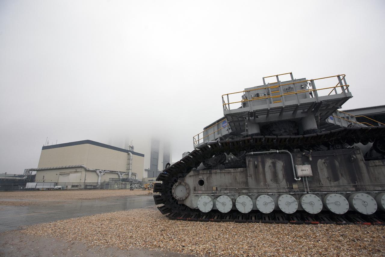
CAPE CANAVERAL, Fla. – Crawler-transporter 2, or CT-2, travels along the crawlerway toward the Vehicle Assembly Building, or VAB, at NASA’s Kennedy Space Center in Florida. The VAB is partially hidden by fog. The Ground Systems Development and Operations Program completed a roller bearing assembly test on CT-2 truck sections A and C. The left- and right-hand steering was tested in both directions. The temperature of the roller assemblies was monitored and recorded. Engineers and technicians performed visual inspections of the roller bearing pumps, valves and lines to ensure that the grease injectors worked properly and provided the required flow of grease to the new roller assemblies. Work continues in high bay 2 to upgrade CT-2. The modifications are designed to ensure CT-2’s ability to transport launch vehicles currently in development, such as the agency’s Space Launch System, to the launch pad. The Ground Systems Development and Operations Program office at Kennedy is overseeing the upgrades. For more than 45 years the crawler-transporters were used to transport the mobile launcher platform and the Apollo-Saturn V rockets and, later, space shuttles to Launch Pads 39A and B. For more information, visit: http:__www.nasa.gov_exploration_systems_ground_crawler-transporter. Photo credit: NASA_Kim Shiflett
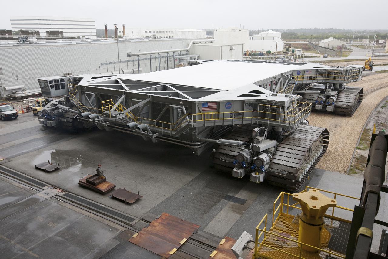
CAPE CANAVERAL, Fla. – Crawler-transporter 2, or CT-2, nears the entrance to the Vehicle Assembly Building at NASA’s Kennedy Space Center in Florida. The Ground Systems Development and Operations Program completed a roller bearing assembly test on CT-2 truck sections A and C. The left- and right-hand steering was tested in both directions. The temperature of the roller assemblies was monitored and recorded as it traveled along the crawlerway. Engineers and technicians performed visual inspections of the roller bearing pumps, valves and lines to ensure that the grease injectors worked properly and provided the required flow of grease to the new roller assemblies. Work continues in high bay 2 to upgrade CT-2. The modifications are designed to ensure CT-2’s ability to transport launch vehicles currently in development, such as the agency’s Space Launch System, to the launch pad. The Ground Systems Development and Operations Program office at Kennedy is overseeing the upgrades. For more than 45 years the crawler-transporters were used to transport the mobile launcher platform and the Apollo-Saturn V rockets and, later, space shuttles to Launch Pads 39A and B. For more information, visit: http:__www.nasa.gov_exploration_systems_ground_crawler-transporter. Photo credit: NASA_Kim Shiflett
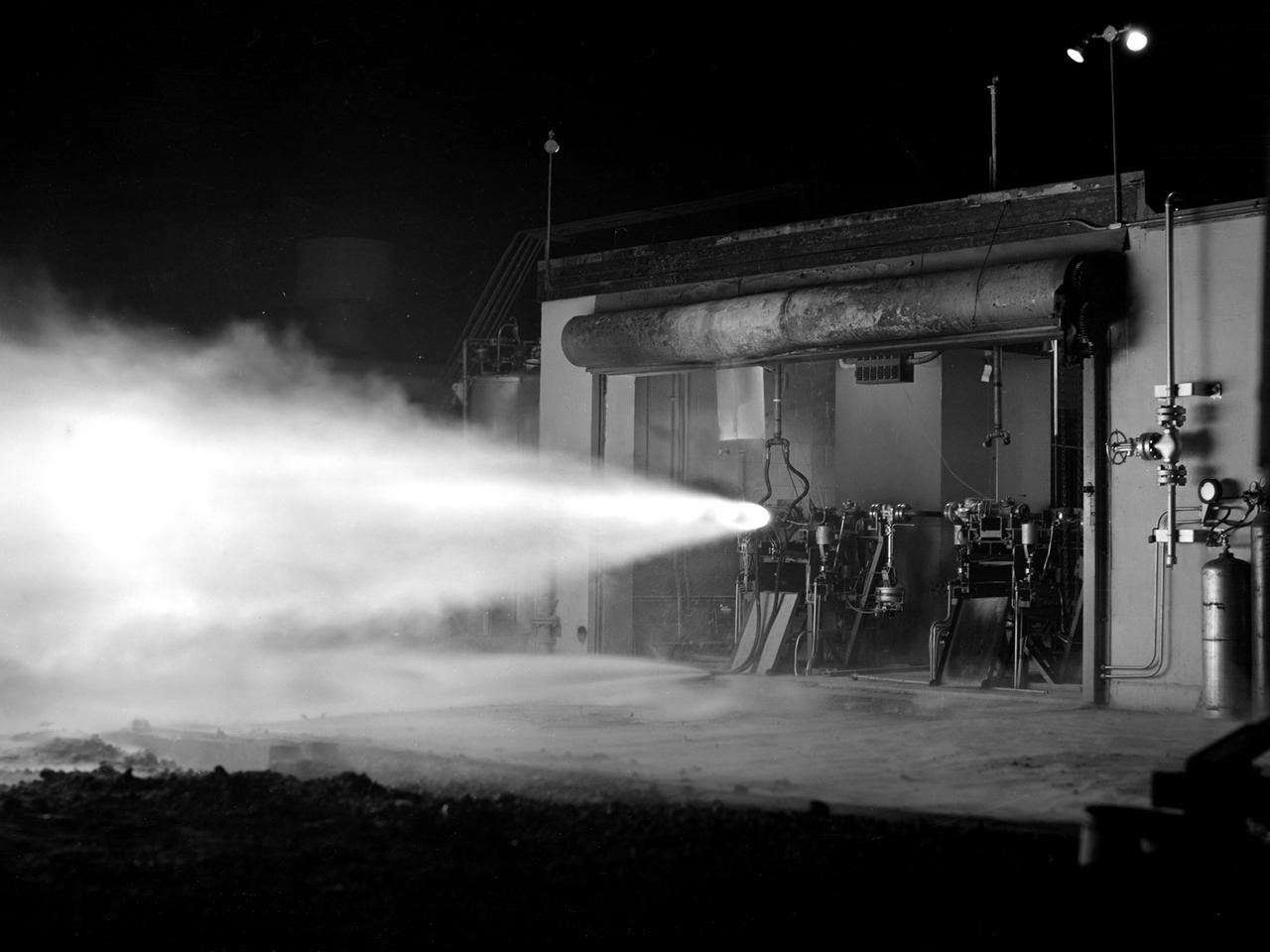
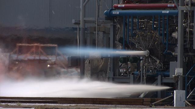
A rocket using high-energy propellant is fired from the Rocket Laboratory at the National Advisory Committee for Aeronautics (NACA) Lewis Flight Propulsion Laboratory. The Rocket Lab was a collection of ten one-story cinderblock test cells located behind earthen barriers at the western edge of the campus. The rocket engines tested there were comparatively small, but the Lewis researchers were able to study different configurations, combustion performance, and injectors and nozzle design. The rockets were generally mounted horizontally and fired, as seen in this photograph of Test Cell No. 22. A group of fuels researchers at Lewis refocused their efforts after World War II in order to explore high energy propellants, combustion, and cooling. Research in these three areas began in 1945 and continued through the 1960s. The group of rocket researches was not elevated to a division branch until 1952. The early NACA Lewis work led to the development of liquid hydrogen as a viable propellant in the late 1950s. Following the 1949 reorganization of the research divisions, the rocket group began working with high-energy propellants such as diborane, pentaborane, and hydrogen. The lightweight fuels offered high levels of energy but were difficult to handle and required large tanks. In late 1954, Lewis researchers studied the combustion characteristics of gaseous hydrogen in a turbojet combustor. Despite poor mixing of the fuel and air, it was found that the hydrogen yielded more than a 90-percent efficiency. Liquid hydrogen became the focus of Lewis researchers for the next 15 years.
Under the goals of the Vision for Space Exploration, Ares I is a chief component of the cost-effective space transportation infrastructure being developed by NASA's Constellation Program. This transportation system will safely and reliably carry human explorers back to the moon, and then onward to Mars and other destinations in the solar system. The Ares I effort includes multiple project element teams at NASA centers and contract organizations around the nation, and is managed by the Exploration Launch Projects Office at NASA's Marshall Space Flight Center (MFSC). ATK Launch Systems near Brigham City, Utah, is the prime contractor for the first stage booster. ATK's subcontractor, United Space Alliance of Houston, is designing, developing and testing the parachutes at its facilities at NASA's Kennedy Space Center in Florida. NASA's Johnson Space Center in Houston hosts the Constellation Program and Orion Crew Capsule Project Office and provides test instrumentation and support personnel. Together, these teams are developing vehicle hardware, evolving proven technologies, and testing components and systems. Their work builds on powerful, reliable space shuttle propulsion elements and nearly a half-century of NASA space flight experience and technological advances. Ares I is an inline, two-stage rocket configuration topped by the Crew Exploration Vehicle, its service module, and a launch abort system. The launch vehicle's first stage is a single, five-segment reusable solid rocket booster derived from the Space Shuttle Program's reusable solid rocket motor that burns a specially formulated and shaped solid propellant called polybutadiene acrylonitrile (PBAN). The second or upper stage will be propelled by a J-2X main engine fueled with liquid oxygen and liquid hydrogen. This HD video image depicts a test firing of a 40k subscale J2X injector at MSFC's test stand 115. (Highest resolution available)
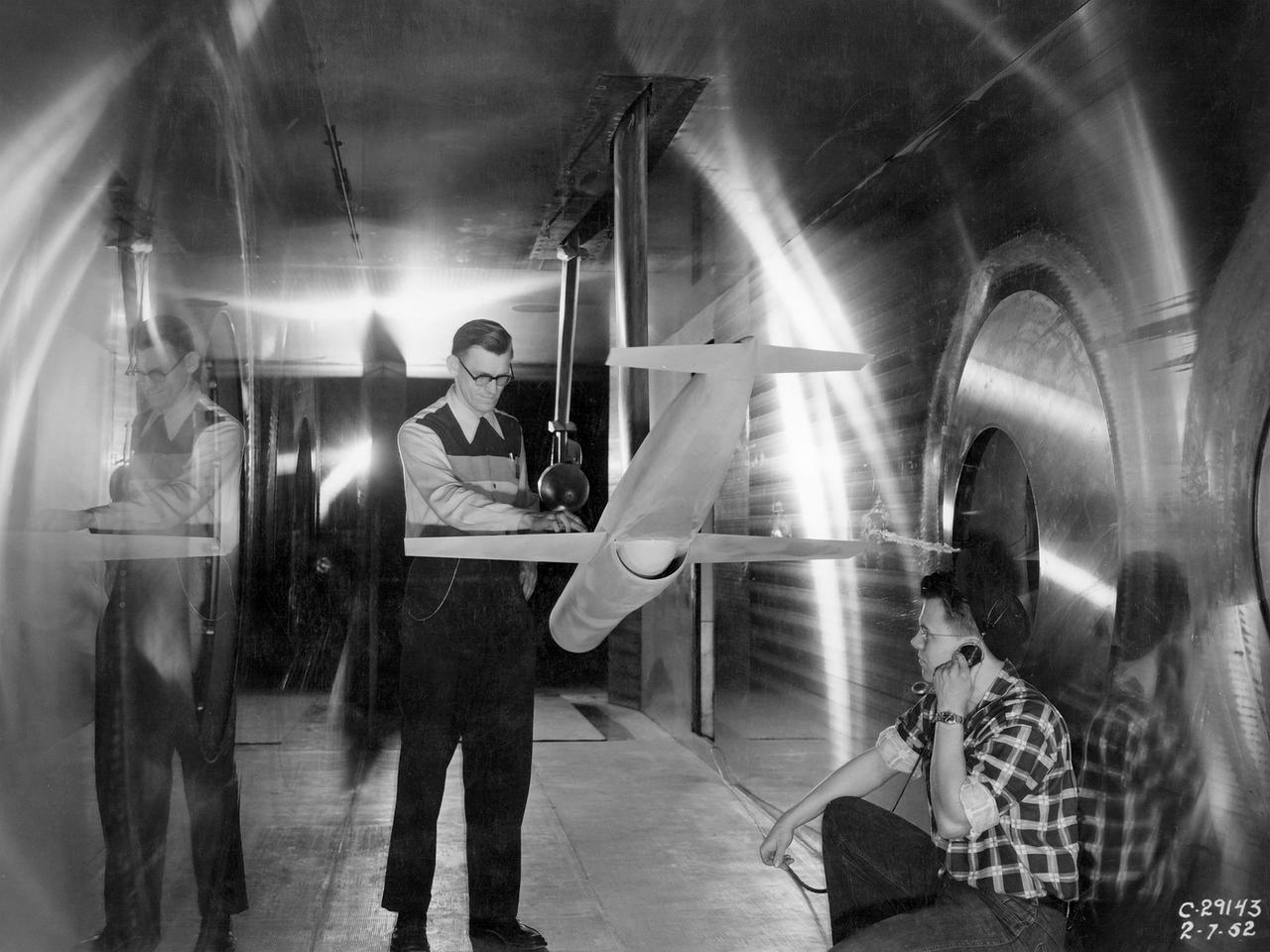
A researcher at the National Advisory Committee for Aeronautics (NACA) Lewis Flight Propulsion Laboratory checks the setup of a RJM-2 ramjet model in the test section of the 8- by 6-Foot Supersonic Wind Tunnel. The 8- by 6 was not only the laboratory’s first large supersonic wind tunnel, but it was also the NACA’s first facility capable of testing an operating engine at supersonic speeds. The 8- by 6-foot tunnel has been used to study engine inlets, fuel injectors, flameholders, exit nozzles, and controls on ramjet and turbojet propulsion systems. The 8-foot wide and 6-foot tall test section consisted of 1-inch thick steel plates with hatches on the floor and ceiling to facilitate the installation of the test article. The two windows seen on the right wall allowed photographic equipment to be set up. The test section was modified in 1956 to accommodate transonic research. NACA engineers drilled 4,700 holes into the test section walls to reduce transonic pressure disturbances and shock waves. NACA Lewis undertook an extensive research program on ramjets in the 1940s using several of its facilities. Ramjets provide a very simple source of propulsion. They are basically a tube which ingests high speed air, ignites it, and then expels the heated air at a significantly higher velocity. Ramjets are extremely efficient and powerful but can only operate at high speeds. Therefore, they require a booster rocket or aircraft drop to accelerate them to high speeds before they can operate.