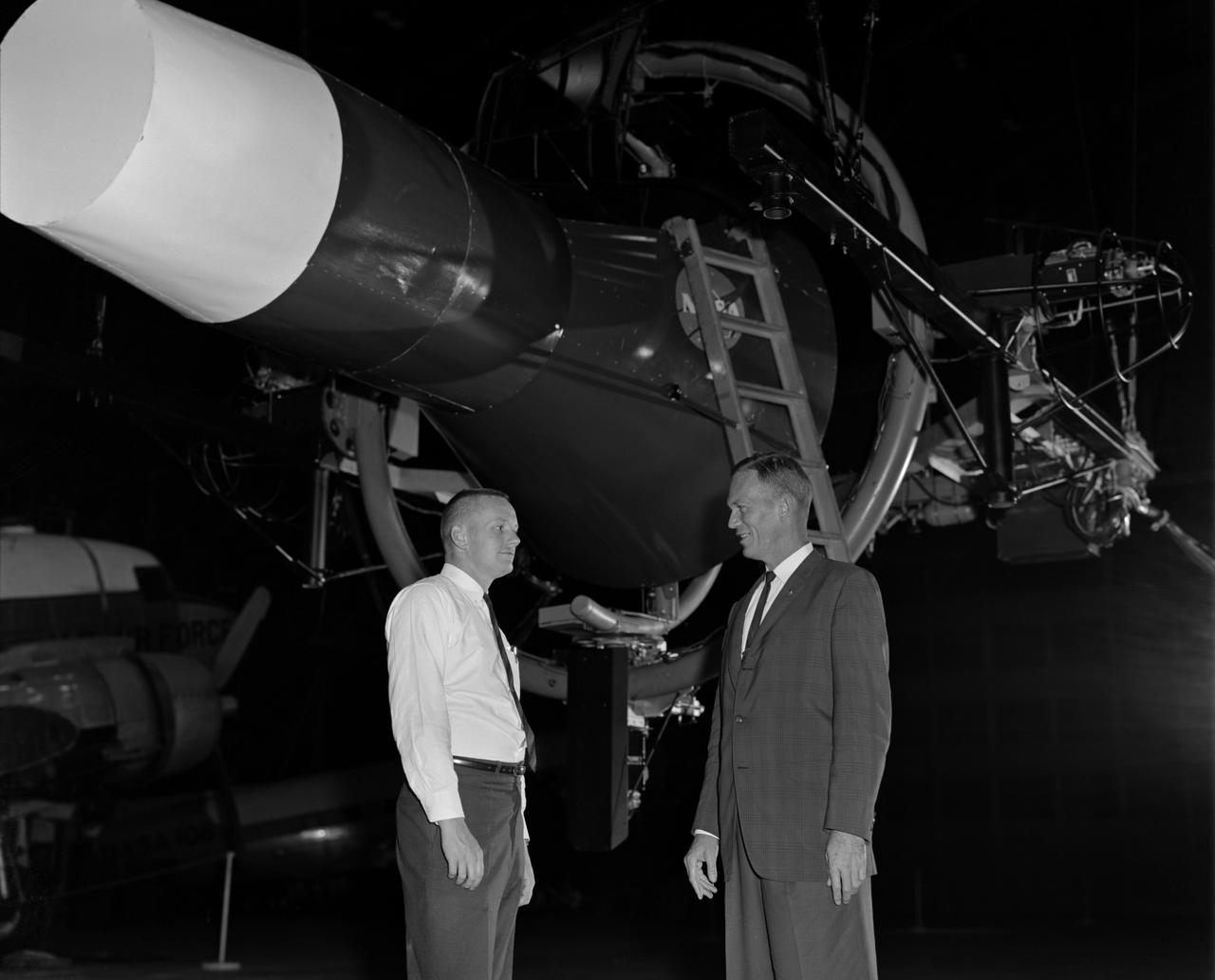
Astronaut Neil Armstrong (left) was one of 14 astronauts, 8 NASA test pilots, and 2 McDonnell test pilots who took part in simulator studies. Armstrong was the first astronaut to participate (November 6, 1963). A.W. Vogeley described the simulator in his paper "Discussion of Existing and Planned Simulators For Space Research," "Many of the astronauts have flown this simulator in support of the Gemini studies and they, without exception, appreciated the realism of the visual scene. The simulator has also been used in the development of pilot techniques to handle certain jet malfunctions in order that aborts could be avoided. In these situations large attitude changes are sometimes necessary and the false motion cues that were generated due to earth gravity were somewhat objectionable; however, the pilots were readily able to overlook these false motion cues in favor of the visual realism." Roy F. Brissenden, noted in his paper "Initial Operations with Langley's Rendezvous Docking Facility," "The basic Gemini control studies developed the necessary techniques and demonstrated the ability of human pilots to perform final space docking with the specified Gemini-Agena systems using only visual references. ... Results... showed that trained astronauts can effect the docking with direct acceleration control and even with jet malfunctions as long as good visual conditions exist.... Probably more important than data results was the early confidence that the astronauts themselves gained in their ability to perform the maneuver in the ultimate flight mission." Francis B. Smith, noted in his paper "Simulators for Manned Space Research," "Some major areas of interest in these flights were fuel requirements, docking accuracies, the development of visual aids to assist alignment of the vehicles, and investigation of alternate control techniques with partial failure modes. However, the familiarization and confidence developed by the astronaut through flying and safely docking the simulator during these tests was one of the major contributions. For example, it was found that fuel used in docking from 200 feet typically dropped from about 20 pounds to 7 pounds after an astronaut had made a few training flights." -- Published in Barton C. Hacker and James M. Grimwood, On the Shoulders of Titans: A History of Project Gemini, NASA SP-4203; A.W. Vogeley, "Discussion of Existing and Planned Simulators For Space Research," Paper presented at the Conference on the Role of Simulation in Space Technology, August 17-21, 1964; Roy F. Brissenden, "Initial Operations with Langley's Rendezvous Docking Facility," Langley Working Paper, LWP-21, 1964; Francis B. Smith, "Simulators for Manned Space Research," Paper presented at the 1966 IEEE International convention, March 21-25, 1966.
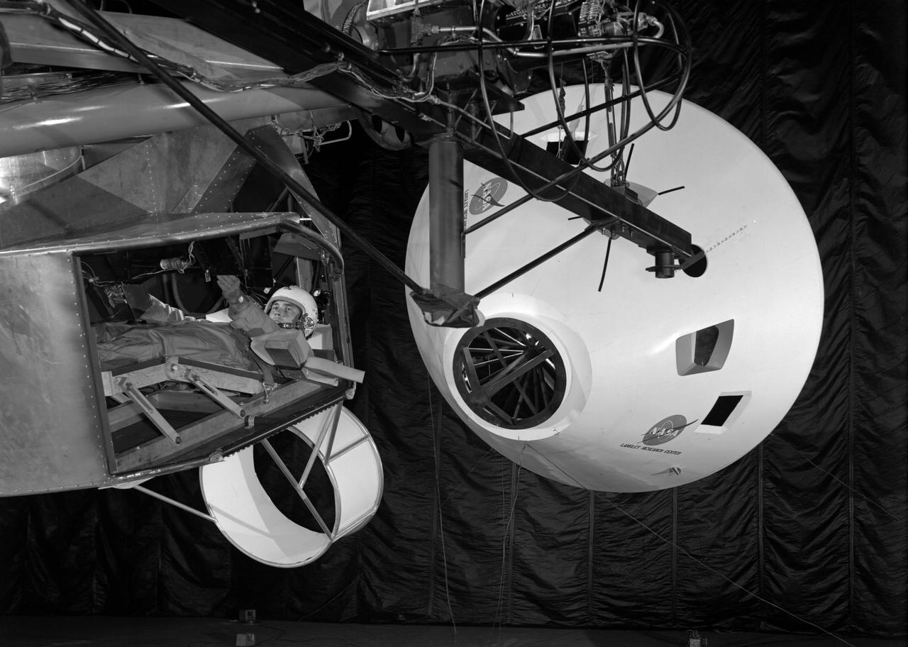
Originally the Rendezvous was used by the astronauts preparing for Gemini missions. The Rendezvous Docking Simulator was then modified and used to develop docking techniques for the Apollo program. The pilot is shown maneuvering the LEM into position for docking with a full-scale Apollo Command Module. From A.W. Vogeley, Piloted Space-Flight Simulation at Langley Research Center, Paper presented at the American Society of Mechanical Engineers, 1966 Winter Meeting, New York, NY, November 27 - December 1, 1966. The Rendezvous Docking Simulator and also the Lunar Landing Research Facility are both rather large moving-base simulators. It should be noted, however, that neither was built primarily because of its motion characteristics. The main reason they were built was to provide a realistic visual scene. A secondary reason was that they would provide correct angular motion cues (important in control of vehicle short-period motions) even though the linear acceleration cues would be incorrect. Apollo Rendezvous Docking Simulator: Langley s Rendezvous Docking Simulator was developed by NASA scientists to study the complex task of docking the Lunar Excursion Module with the Command Module in Lunar orbit.
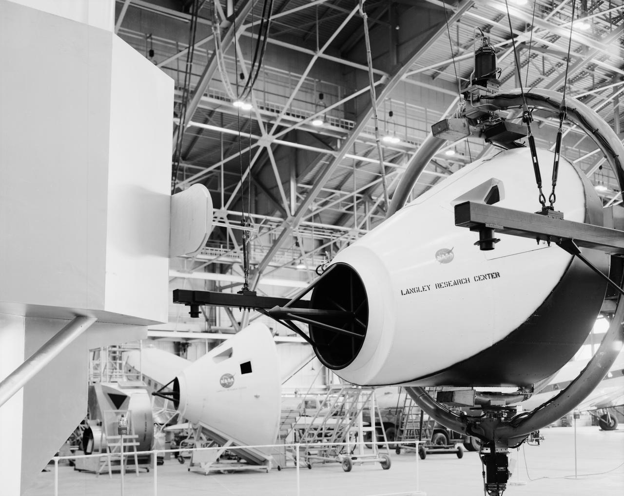
Originally the Rendezvous was used by the astronauts preparing for Gemini missions. The Rendezvous Docking Simulator was then modified and used to develop docking techniques for the Apollo program. This picture shows a later configuration of the Apollo docking with the LEM target. A.W. Vogeley described the simulator as follows: The Rendezvous Docking Simulator and also the Lunar Landing Research Facility are both rather large moving-base simulators. It should be noted, however, that neither was built primarily because of its motion characteristics. The main reason they were built was to provide a realistic visual scene. A secondary reason was that they would provide correct angular motion cues (important in control of vehicle short-period motions) even though the linear acceleration cues would be incorrect. -- Published in A.W. Vogeley, Piloted Space-Flight Simulation at Langley Research Center, Paper presented at the American Society of Mechanical Engineers, 1966 Winter Meeting, New York, NY, November 27 - December 1, 1966.
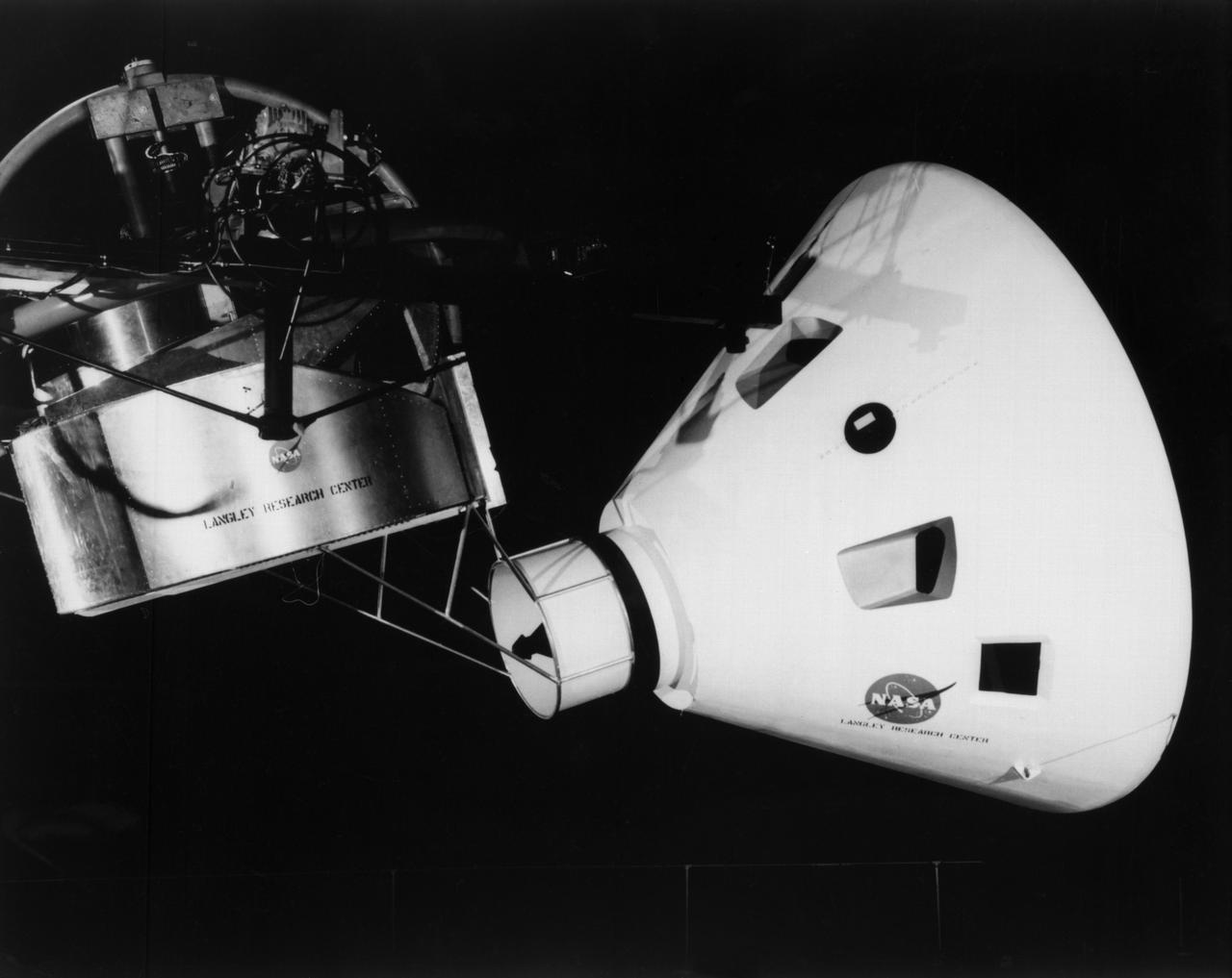
Originally the Rendezvous was used by the astronauts preparing for Gemini missions. The Rendezvous Docking Simulator was then modified and used to develop docking techniques for the Apollo program. "The LEM pilot's compartment, with overhead window and the docking ring (idealized since the pilot cannot see it during the maneuvers), is shown docked with the full-scale Apollo Command Module." A.W. Vogeley described the simulator as follows: "The Rendezvous Docking Simulator and also the Lunar Landing Research Facility are both rather large moving-base simulators. It should be noted, however, that neither was built primarily because of its motion characteristics. The main reason they were built was to provide a realistic visual scene. A secondary reason was that they would provide correct angular motion cues (important in control of vehicle short-period motions) even though the linear acceleration cues would be incorrect." -- Published in A.W. Vogeley, "Piloted Space-Flight Simulation at Langley Research Center," Paper presented at the American Society of Mechanical Engineers, 1966 Winter Meeting, New York, NY, November 27 - December 1, 1966;
Originally the Rendezvous was used by the astronauts preparing for Gemini missions. The Rendezvous Docking Simulator was then modified and used to develop docking techniques for the Apollo program. "The LEM pilot's compartment, with overhead window and the docking ring (idealized since the pilot cannot see it during the maneuvers), is shown docked with the full-scale Apollo Command Module." A.W. Vogeley described the simulator as follows: "The Rendezvous Docking Simulator and also the Lunar Landing Research Facility are both rather large moving-base simulators. It should be noted, however, that neither was built primarily because of its motion characteristics. The main reason they were built was to provide a realistic visual scene. A secondary reason was that they would provide correct angular motion cues (important in control of vehicle short-period motions) even though the linear acceleration cues would be incorrect." -- Published in A.W. Vogeley, "Piloted Space-Flight Simulation at Langley Research Center," Paper presented at the American Society of Mechanical Engineers, 1966 Winter Meeting, New York, NY, November 27 - December 1, 1966;
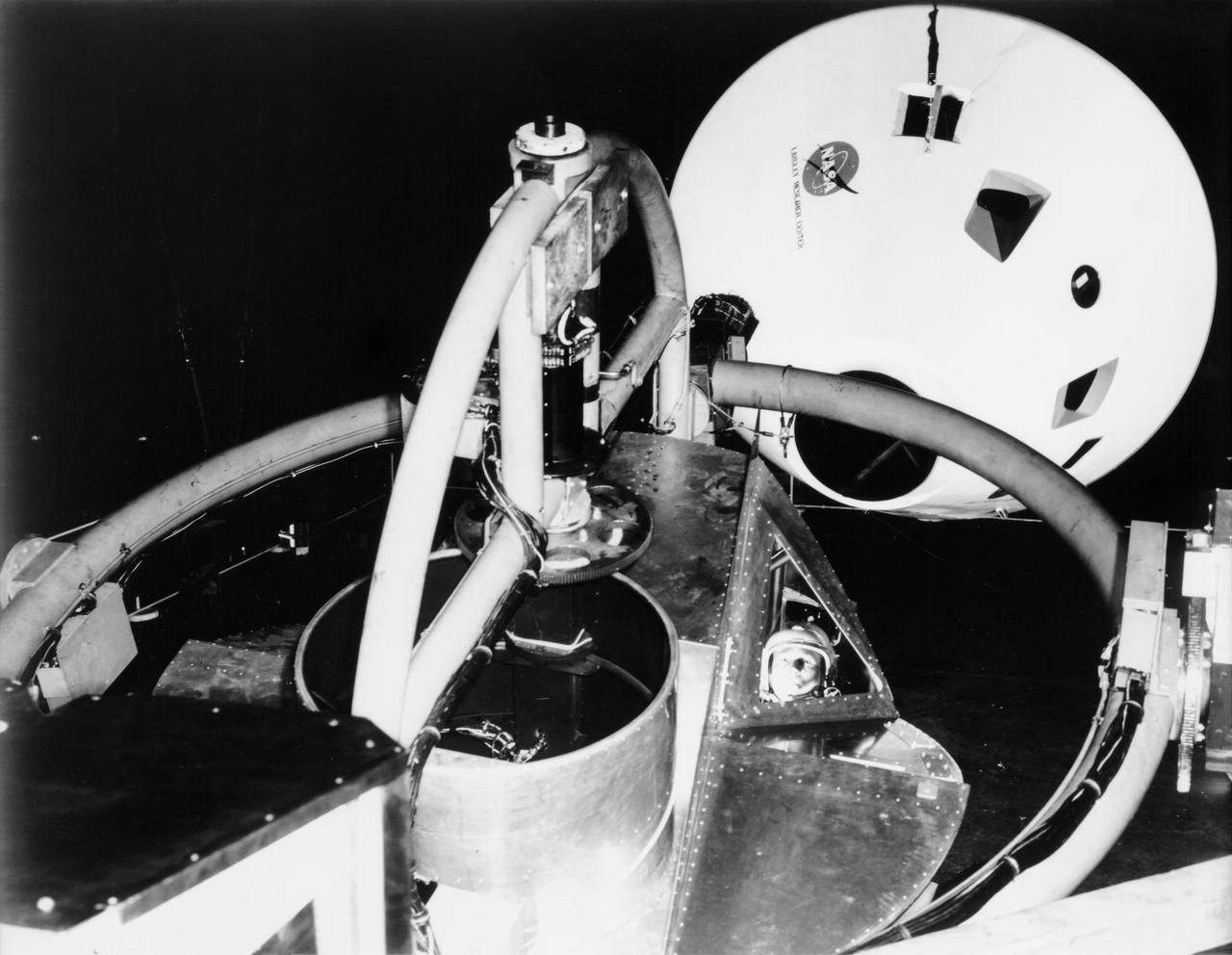
![Multiple exposure of Gemini rendezvous docking simulator. Francis B. Smith wrote in his paper "Simulators for Manned Space Research," "The rendezvous and docking operation of the Gemini spacecraft with the Agena and of the Apollo Command Module with the Lunar Excursion Module have been the subject of simulator studies for several years. [This figure] illustrates the Gemini-Agena rendezvous docking simulator at Langley. The Gemini spacecraft was supported in a gimbal system by an overhead crane and gantry arrangement which provided 6 degrees of freedom - roll, pitch, yaw, and translation in any direction - all controllable by the astronaut in the spacecraft. Here again the controls fed into a computer which in turn provided an input to the servos driving the spacecraft so that it responded to control motions in a manner which accurately simulated the Gemini spacecraft." A.W. Vogeley further described the simulator in his paper "Discussion of Existing and Planned Simulators For Space Research," "Docking operations are considered to start when the pilot first can discern vehicle target size and aspect and terminate, of course, when soft contact is made. ... This facility enables simulation of the docking operation from a distance of 200 feet to actual contact with the target. A full-scale mock-up of the target vehicle is suspended near one end of the track. ... On [the Agena target] we have mounted the actual Agena docking mechanism and also various types of visual aids. We have been able to devise visual aids which have made it possible to accomplish nighttime docking with as much success as daytime docking." -- Published in Barton C. Hacker and James M. Grimwood, On the Shoulders of Titans: A History of Project Gemini, NASA SP-4203; Francis B. Smith, "Simulators for Manned Space Research," Paper presented at the 1966 IEEE International convention, March 21-25, 1966; A.W. Vogeley, "Discussion of Existing and Planned Simulators For Space Research," Paper presented at the Conference on the Role of Simulation in Space Technology, August 17-21, 1964.](https://images-assets.nasa.gov/image/LRC-1963-B701_P-08973/LRC-1963-B701_P-08973~medium.jpg)
Multiple exposure of Gemini rendezvous docking simulator. Francis B. Smith wrote in his paper "Simulators for Manned Space Research," "The rendezvous and docking operation of the Gemini spacecraft with the Agena and of the Apollo Command Module with the Lunar Excursion Module have been the subject of simulator studies for several years. [This figure] illustrates the Gemini-Agena rendezvous docking simulator at Langley. The Gemini spacecraft was supported in a gimbal system by an overhead crane and gantry arrangement which provided 6 degrees of freedom - roll, pitch, yaw, and translation in any direction - all controllable by the astronaut in the spacecraft. Here again the controls fed into a computer which in turn provided an input to the servos driving the spacecraft so that it responded to control motions in a manner which accurately simulated the Gemini spacecraft." A.W. Vogeley further described the simulator in his paper "Discussion of Existing and Planned Simulators For Space Research," "Docking operations are considered to start when the pilot first can discern vehicle target size and aspect and terminate, of course, when soft contact is made. ... This facility enables simulation of the docking operation from a distance of 200 feet to actual contact with the target. A full-scale mock-up of the target vehicle is suspended near one end of the track. ... On [the Agena target] we have mounted the actual Agena docking mechanism and also various types of visual aids. We have been able to devise visual aids which have made it possible to accomplish nighttime docking with as much success as daytime docking." -- Published in Barton C. Hacker and James M. Grimwood, On the Shoulders of Titans: A History of Project Gemini, NASA SP-4203; Francis B. Smith, "Simulators for Manned Space Research," Paper presented at the 1966 IEEE International convention, March 21-25, 1966; A.W. Vogeley, "Discussion of Existing and Planned Simulators For Space Research," Paper presented at the Conference on the Role of Simulation in Space Technology, August 17-21, 1964.
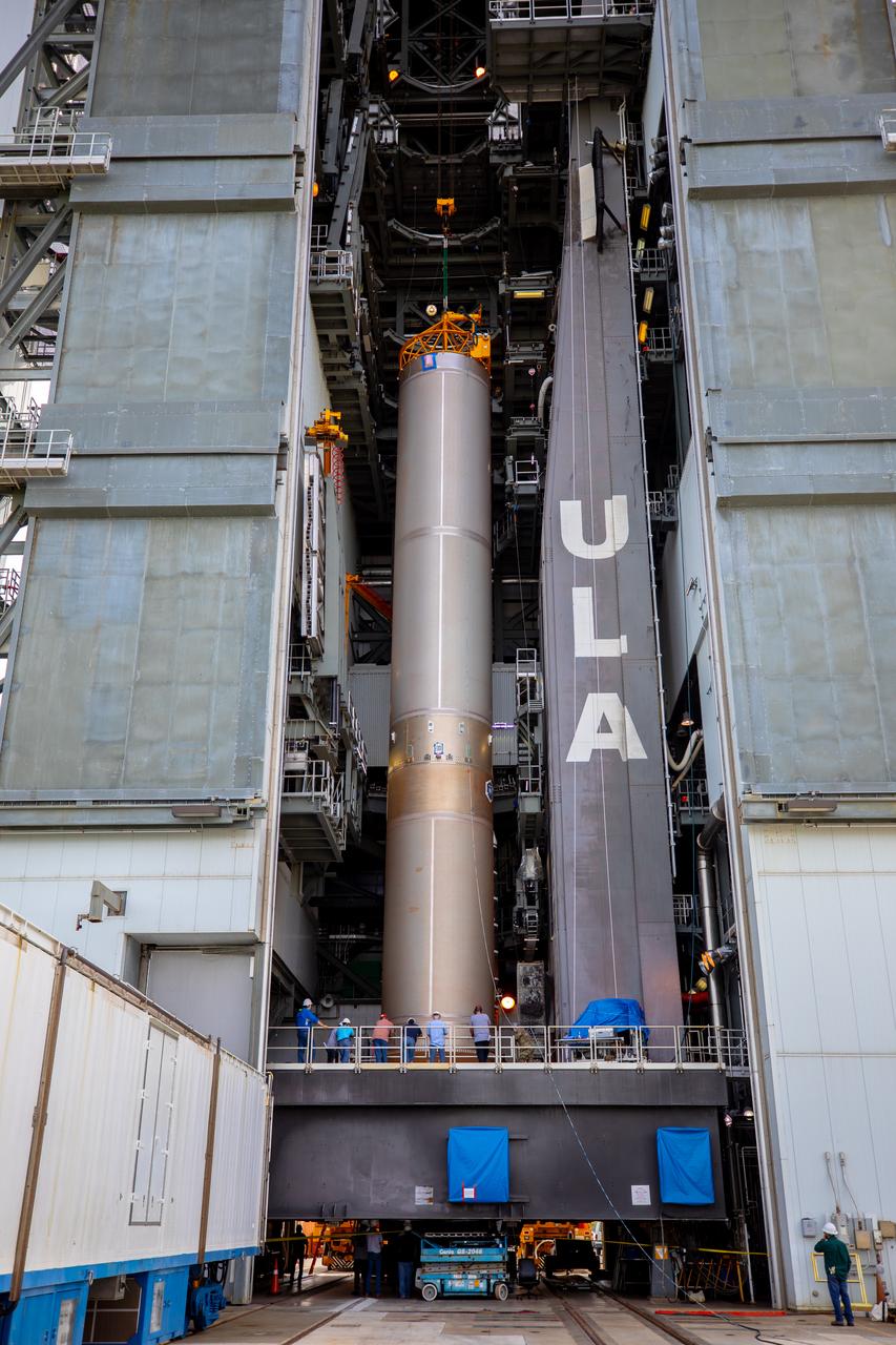
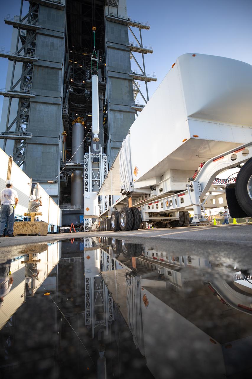
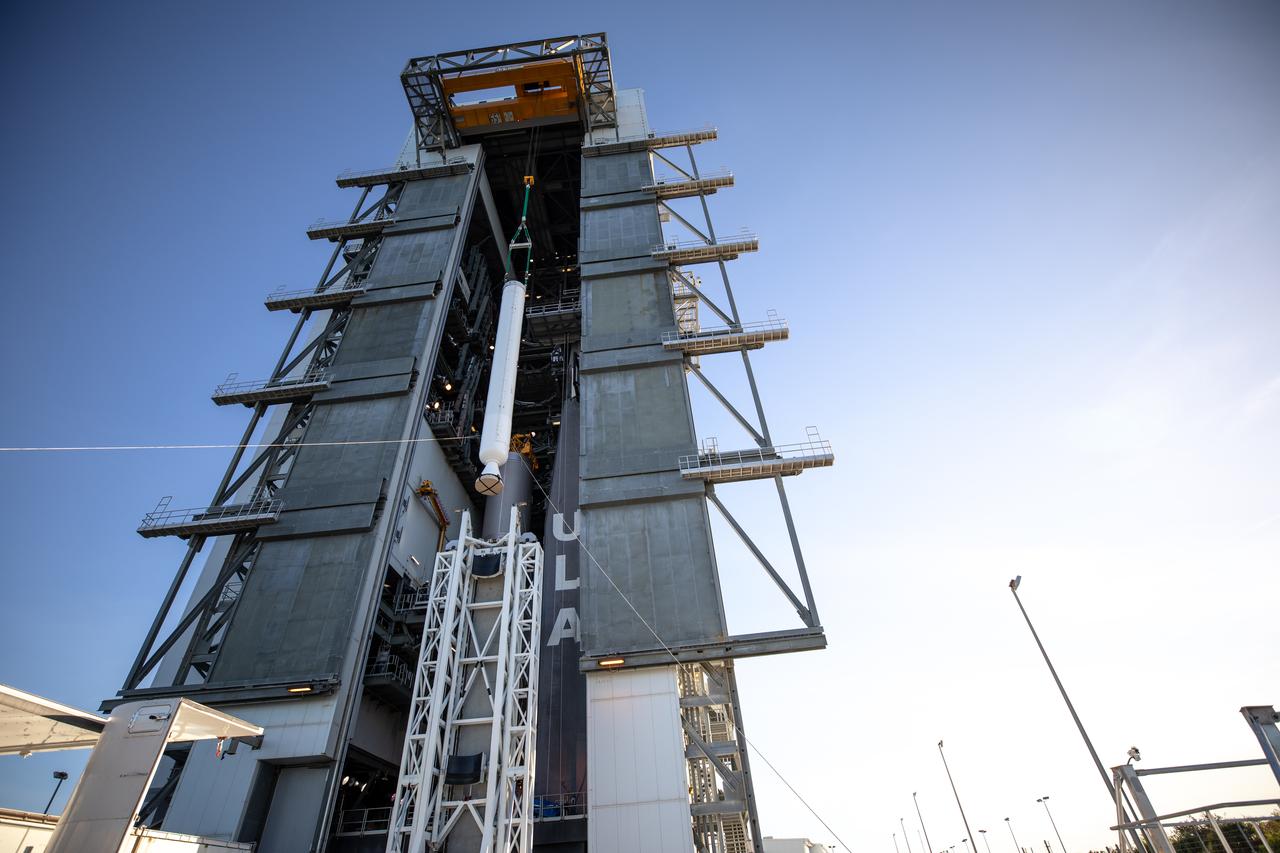
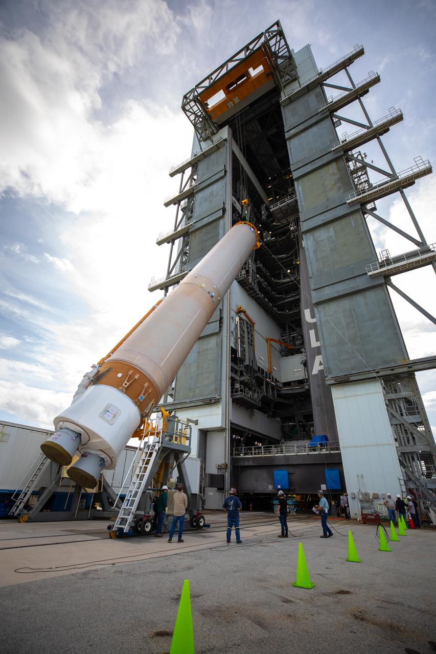
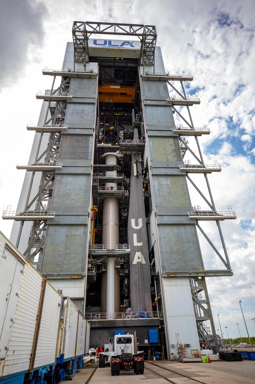
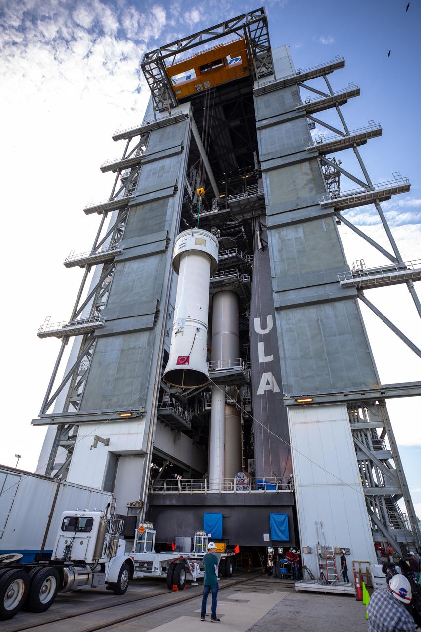
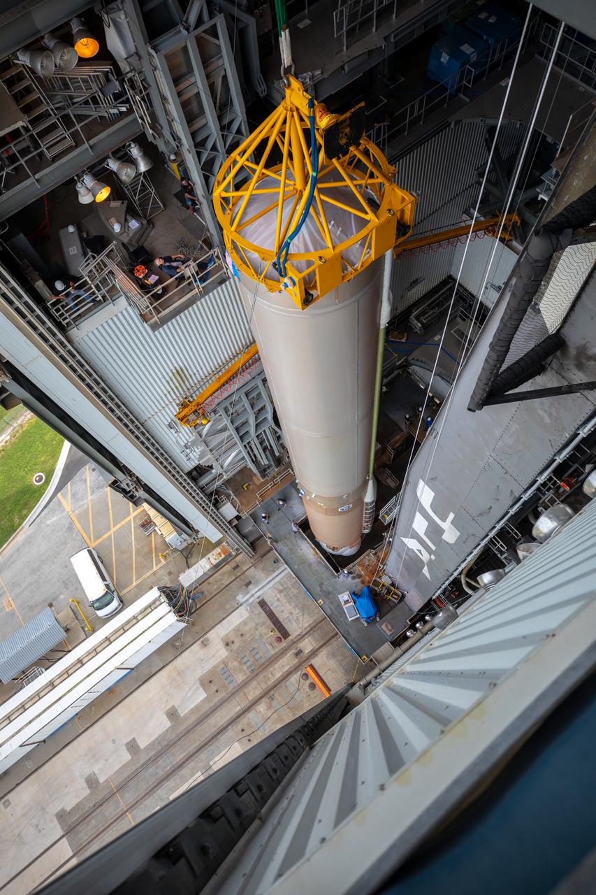
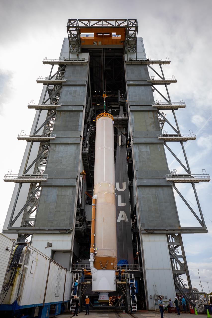
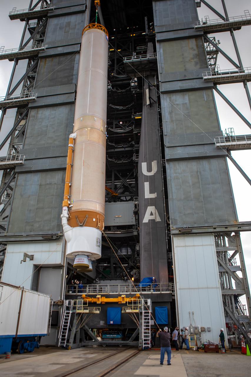
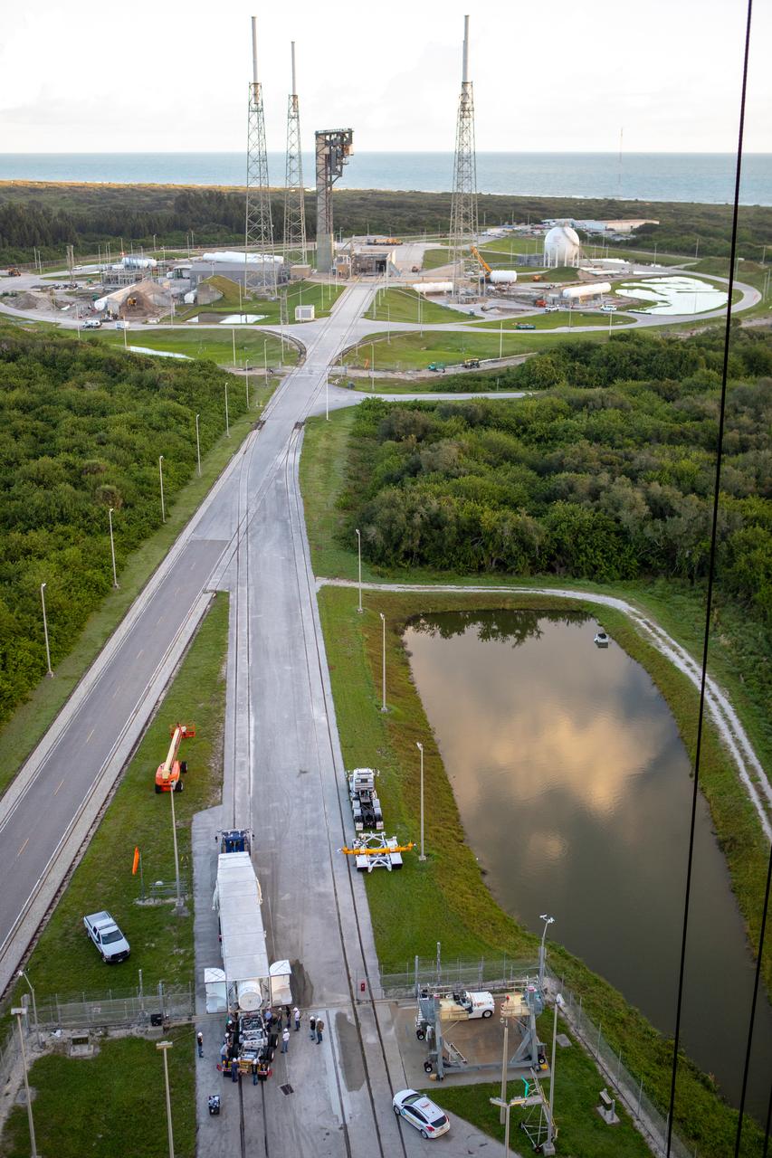
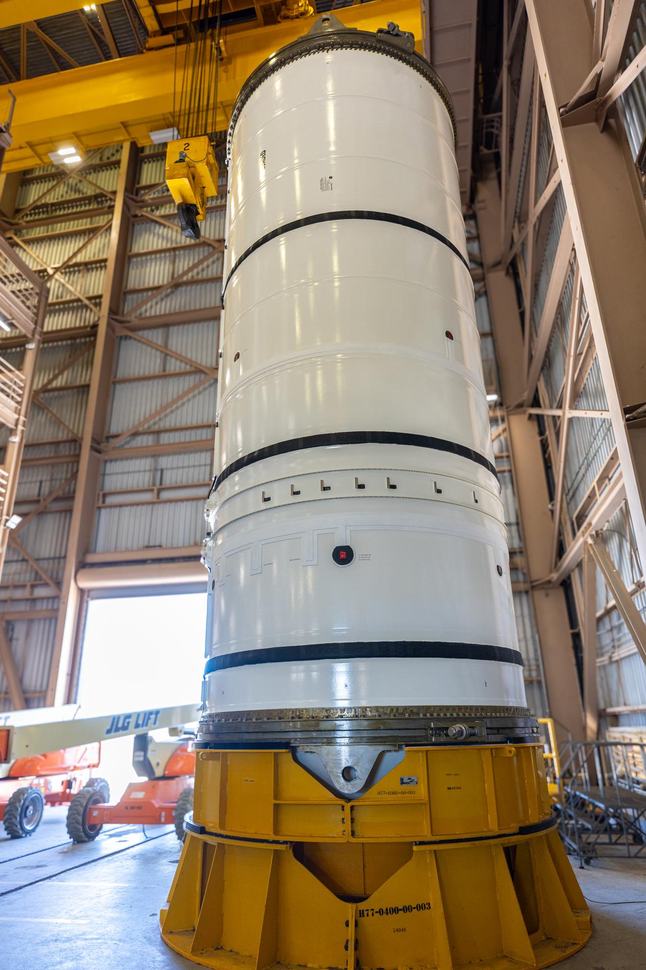
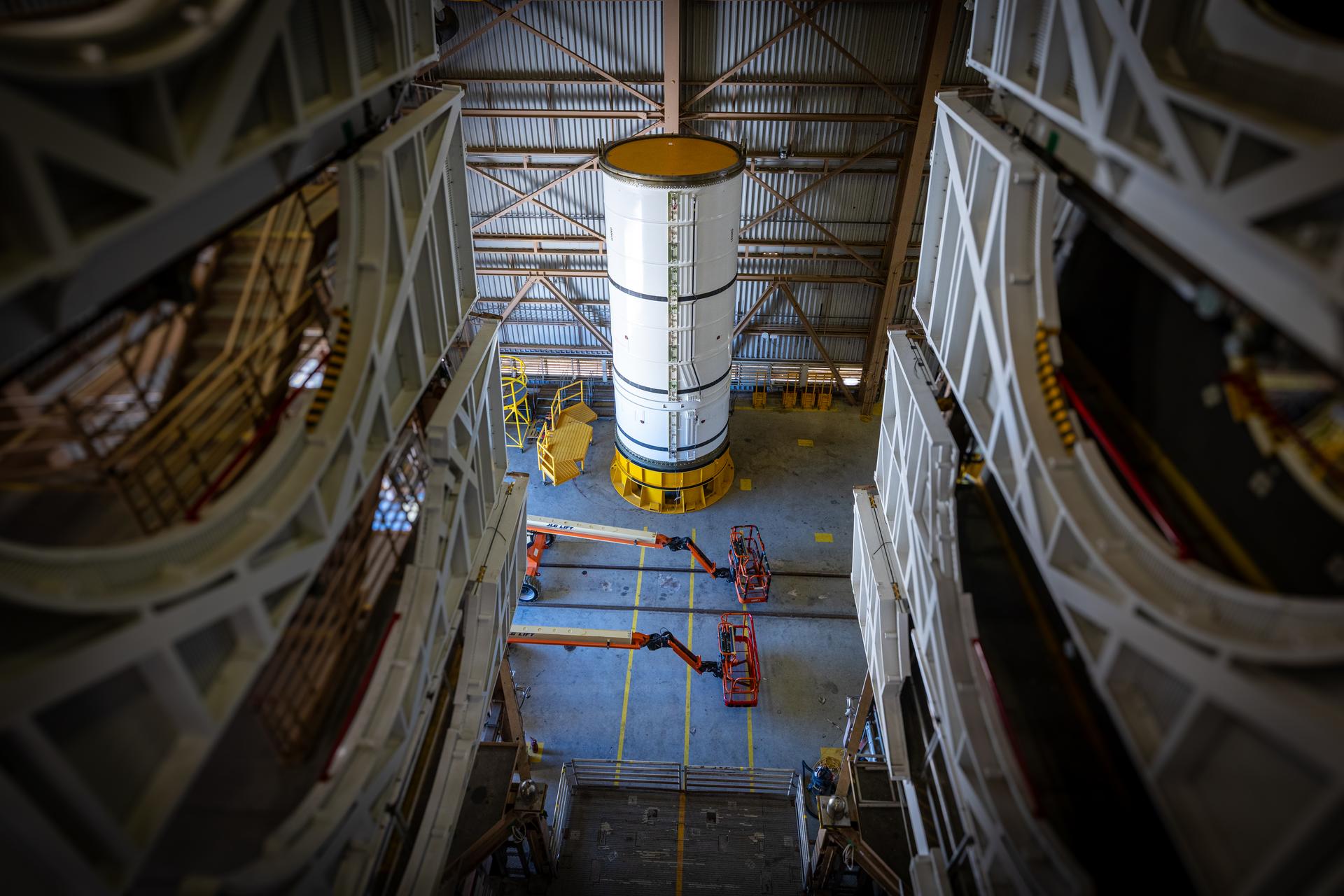
The United Launch Alliance Atlas V first stage is lifted to the vertical position on Nov. 4, 2019, in the Vertical Integration Facility at Space Launch Complex 41 at Cape Canaveral Air Force Station in Florida, in preparation for Boeing’s Orbital Flight Test (OFT). The uncrewed OFT mission will rendezvous and dock Boeing’s CST-100 Starliner spacecraft with the International Space Station as part of NASA’s Commercial Crew Program. Starliner will launch atop the Atlas V rocket from Space Launch Complex 41.
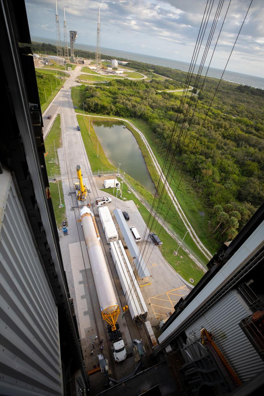
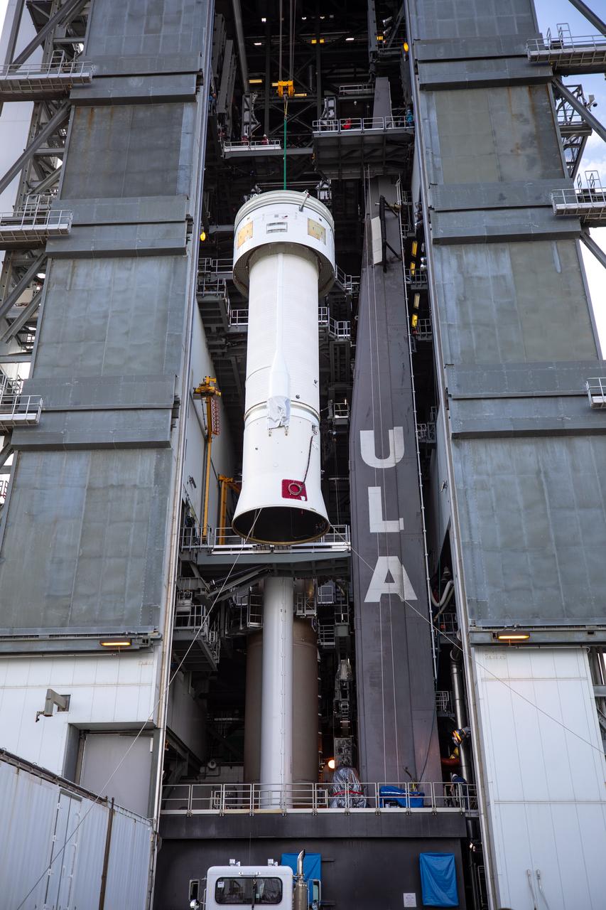
The United Launch Alliance Atlas V first stage is lifted to the vertical position on Nov. 4, 2019, in the Vertical Integration Facility at Space Launch Complex 41 at Cape Canaveral Air Force Station in Florida, in preparation for Boeing’s Orbital Flight Test (OFT). The uncrewed OFT mission will rendezvous and dock Boeing’s CST-100 Starliner spacecraft with the International Space Station as part of NASA’s Commercial Crew Program. Starliner will launch atop the Atlas V rocket from Space Launch Complex 41.
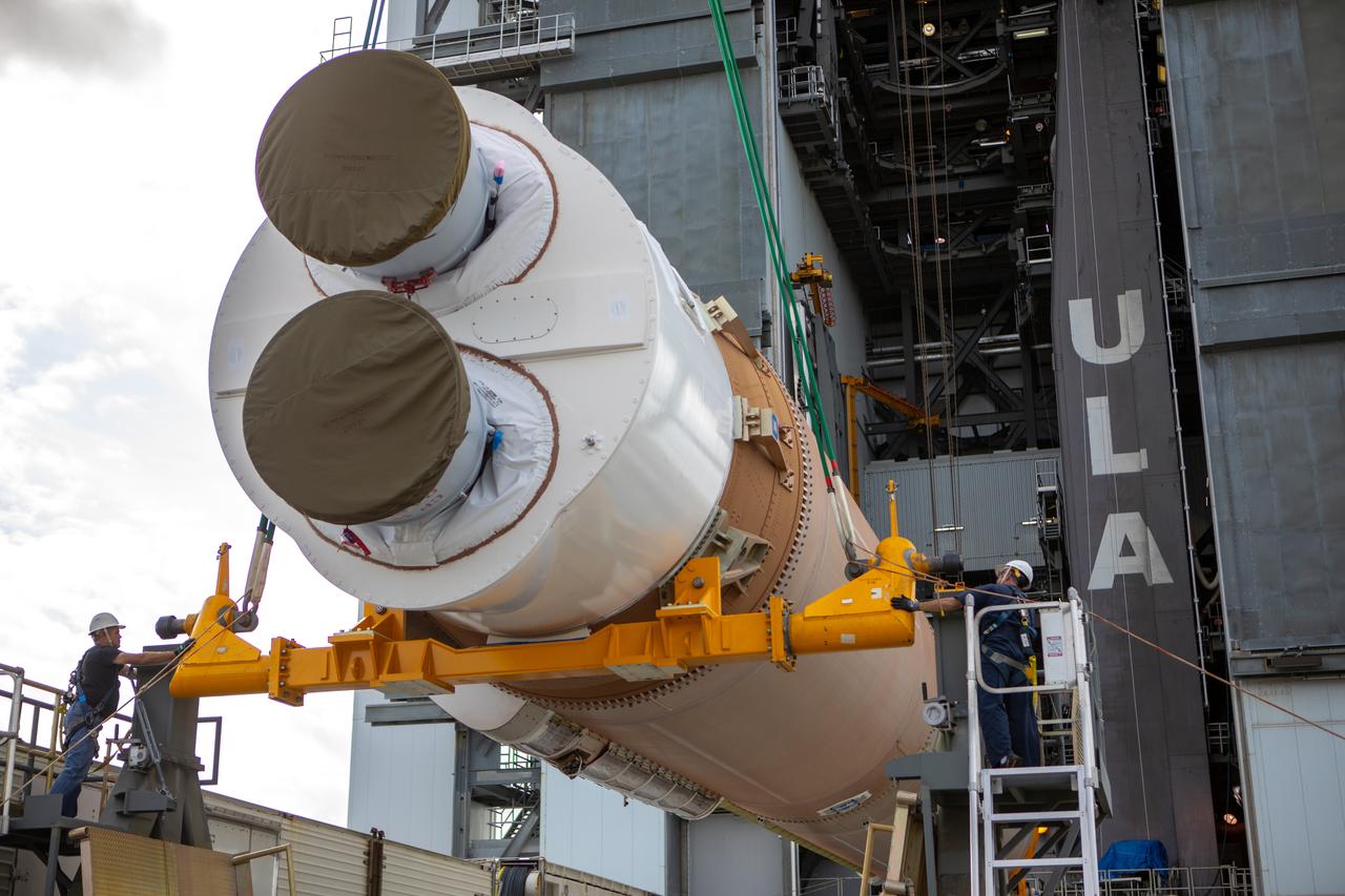
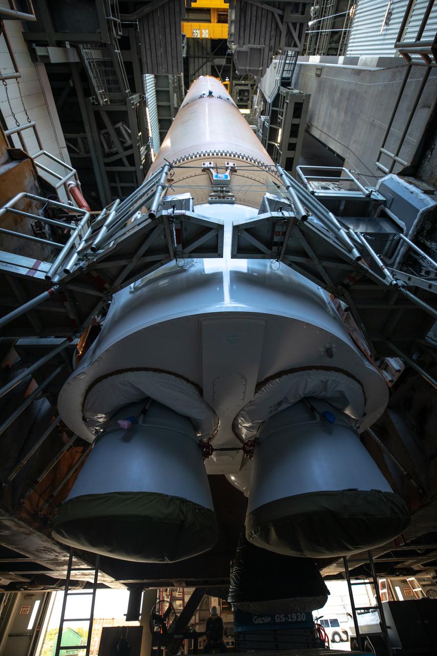
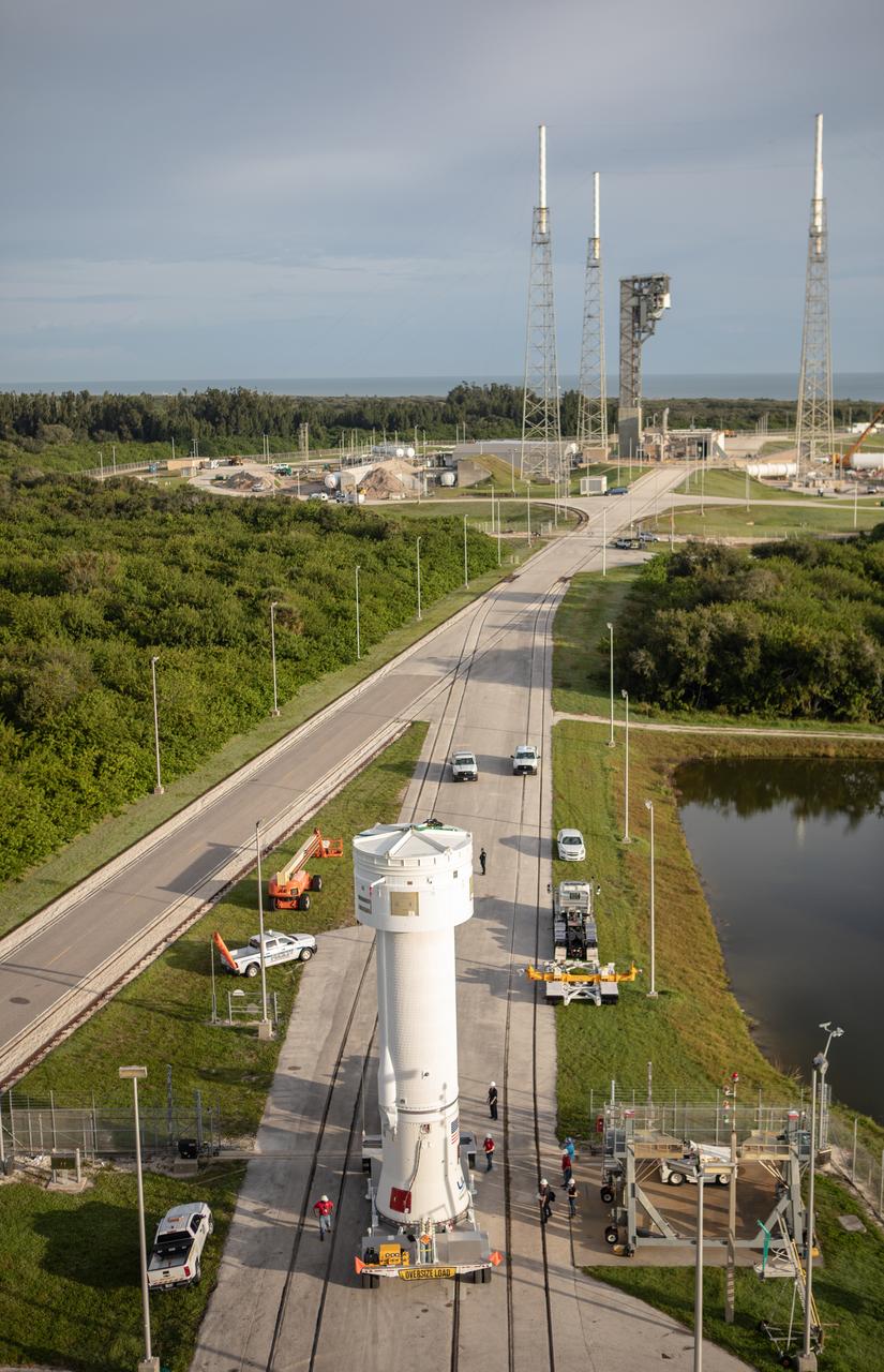
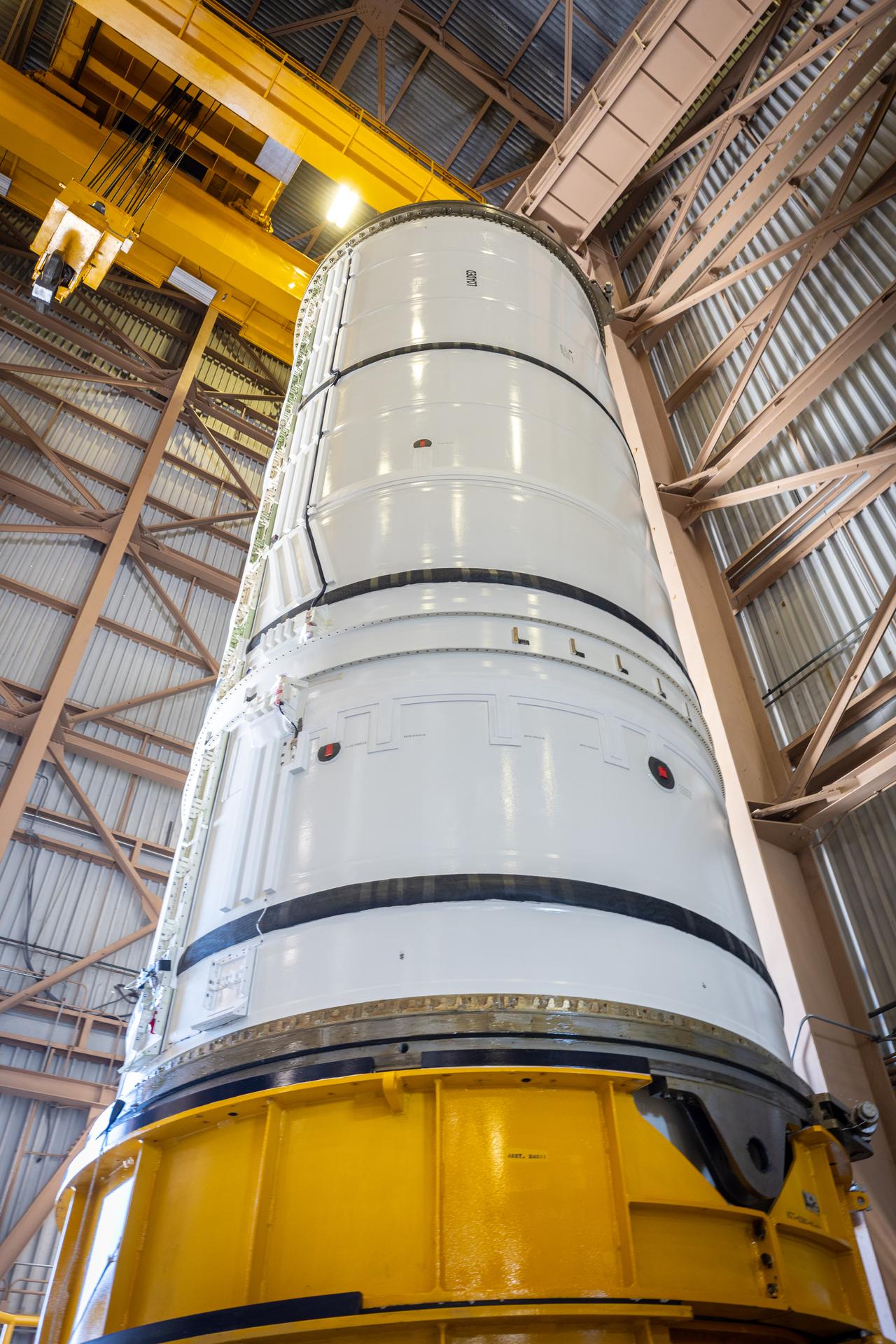
Two solid rocket boosters are mated to a United Launch Alliance Atlas V first stage inside the Vertical Integration Facility at Space Launch Complex 41 at Cape Canaveral Air Force Station in Florida on Nov. 7, 2019, in preparation for Boeing’s Orbital Flight Test (OFT). The uncrewed OFT mission will rendezvous and dock Boeing’s CST-100 Starliner spacecraft with the International Space Station as part of NASA’s Commercial Crew Program. Starliner will launch atop the Atlas V rocket from Space Launch Complex 41.
Two solid rocket boosters are mated to a United Launch Alliance Atlas V first stage inside the Vertical Integration Facility at Space Launch Complex 41 at Cape Canaveral Air Force Station in Florida on Nov. 7, 2019, in preparation for Boeing’s Orbital Flight Test (OFT). The uncrewed OFT mission will rendezvous and dock Boeing’s CST-100 Starliner spacecraft with the International Space Station as part of NASA’s Commercial Crew Program. Starliner will launch atop the Atlas V rocket from Space Launch Complex 41.
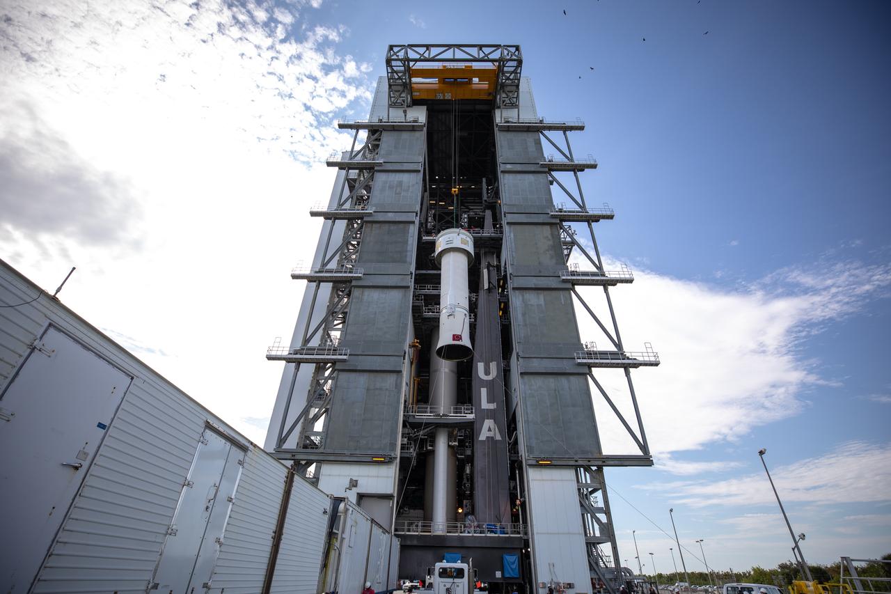
The United Launch Alliance Atlas V first stage is lifted to the vertical position on Nov. 4, 2019, in the Vertical Integration Facility at Space Launch Complex 41 at Cape Canaveral Air Force Station in Florida, in preparation for Boeing’s Orbital Flight Test (OFT). The uncrewed OFT mission will rendezvous and dock Boeing’s CST-100 Starliner spacecraft with the International Space Station as part of NASA’s Commercial Crew Program. Starliner will launch atop the Atlas V rocket from Space Launch Complex 41.
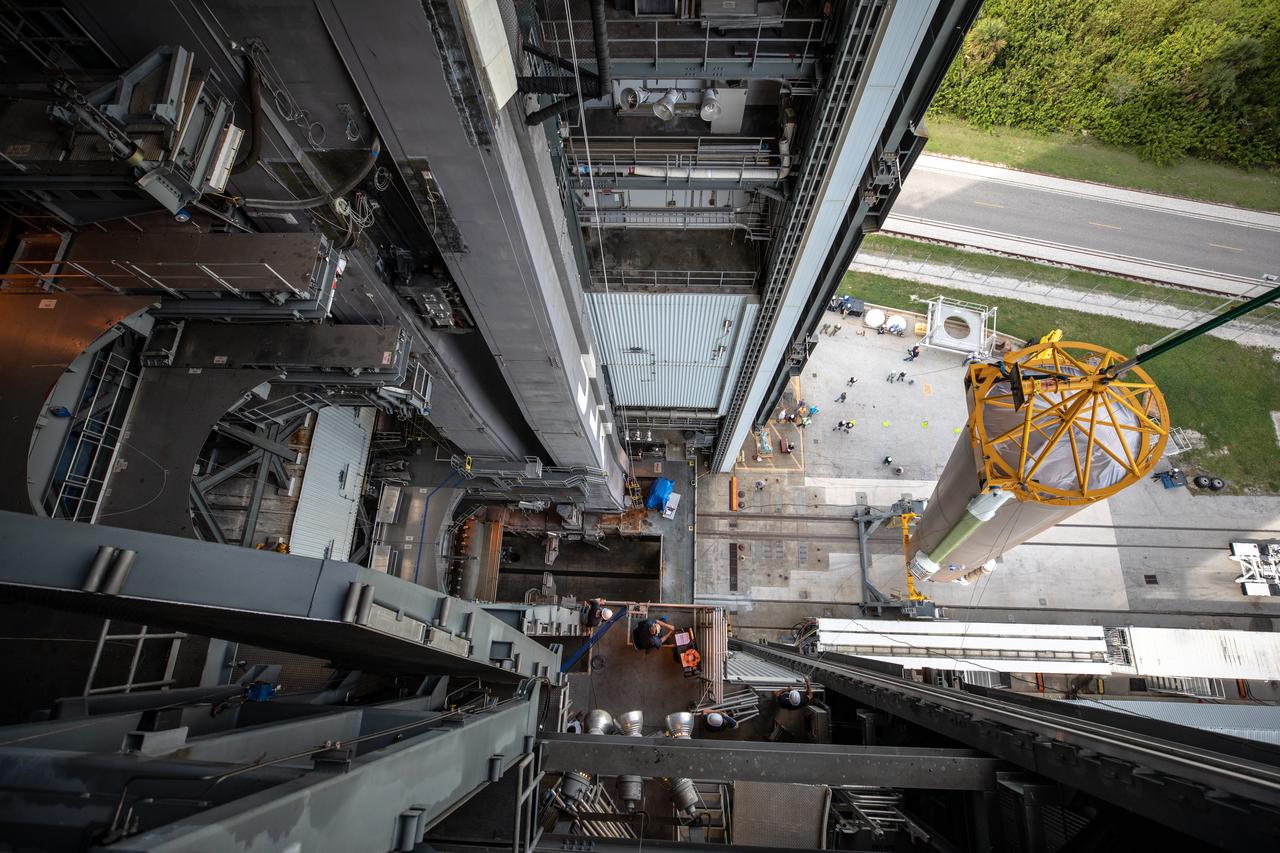
A Centaur upper stage is lifted at the Space Launch Complex 41 Vertical Integration Facility at Florida’s Cape Canaveral Air Force Station on Nov. 8, 2019, for mating to the United Launch Alliance Atlas V first stage in preparation for Boeing’s Orbital Flight Test (OFT). The uncrewed OFT mission will rendezvous and dock Boeing’s CST-100 Starliner spacecraft with the International Space Station as part of NASA’s Commercial Crew Program. Starliner will launch atop the Atlas V rocket from Space Launch Complex 41.
Two solid rocket boosters are mated to a United Launch Alliance Atlas V first stage inside the Vertical Integration Facility at Space Launch Complex 41 at Cape Canaveral Air Force Station in Florida on Nov. 7, 2019, in preparation for Boeing’s Orbital Flight Test (OFT). The uncrewed OFT mission will rendezvous and dock Boeing’s CST-100 Starliner spacecraft with the International Space Station as part of NASA’s Commercial Crew Program. Starliner will launch atop the Atlas V rocket from Space Launch Complex 41.
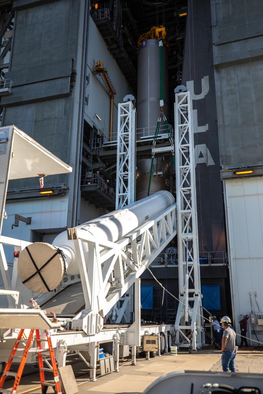
The United Launch Alliance Atlas V first stage is lifted to the vertical position on Nov. 4, 2019, in the Vertical Integration Facility at Space Launch Complex 41 at Cape Canaveral Air Force Station in Florida, in preparation for Boeing’s Orbital Flight Test (OFT). The uncrewed OFT mission will rendezvous and dock Boeing’s CST-100 Starliner spacecraft with the International Space Station as part of NASA’s Commercial Crew Program. Starliner will launch atop the Atlas V rocket from Space Launch Complex 41.
A Centaur upper stage is mated to the United Launch Alliance Atlas V first stage inside the Space Launch Complex 41 Vertical Integration Facility at Florida’s Cape Canaveral Air Force Station on Nov. 8, 2019, in preparation for Boeing’s Orbital Flight Test (OFT). The uncrewed OFT mission will rendezvous and dock Boeing’s CST-100 Starliner spacecraft with the International Space Station as part of NASA’s Commercial Crew Program. Starliner will launch atop the Atlas V rocket from Space Launch Complex 41.
A Centaur upper stage is lifted at the Space Launch Complex 41 Vertical Integration Facility at Florida’s Cape Canaveral Air Force Station on Nov. 8, 2019, for mating to the United Launch Alliance Atlas V first stage in preparation for Boeing’s Orbital Flight Test (OFT). The uncrewed OFT mission will rendezvous and dock Boeing’s CST-100 Starliner spacecraft with the International Space Station as part of NASA’s Commercial Crew Program. Starliner will launch atop the Atlas V rocket from Space Launch Complex 41.
Two solid rocket boosters are mated to a United Launch Alliance Atlas V first stage inside the Vertical Integration Facility at Space Launch Complex 41 at Cape Canaveral Air Force Station in Florida on Nov. 7, 2019, in preparation for Boeing’s Orbital Flight Test (OFT). The uncrewed OFT mission will rendezvous and dock Boeing’s CST-100 Starliner spacecraft with the International Space Station as part of NASA’s Commercial Crew Program. Starliner will launch atop the Atlas V rocket from Space Launch Complex 41.
The United Launch Alliance Atlas V first stage is lifted to the vertical position on Nov. 4, 2019, in the Vertical Integration Facility at Space Launch Complex 41 at Cape Canaveral Air Force Station in Florida, in preparation for Boeing’s Orbital Flight Test (OFT). The uncrewed OFT mission will rendezvous and dock Boeing’s CST-100 Starliner spacecraft with the International Space Station as part of NASA’s Commercial Crew Program. Starliner will launch atop the Atlas V rocket from Space Launch Complex 41.
A Centaur upper stage is lifted at the Space Launch Complex 41 Vertical Integration Facility at Florida’s Cape Canaveral Air Force Station on Nov. 8, 2019, for mating to the United Launch Alliance Atlas V first stage in preparation for Boeing’s Orbital Flight Test (OFT). The uncrewed OFT mission will rendezvous and dock Boeing’s CST-100 Starliner spacecraft with the International Space Station as part of NASA’s Commercial Crew Program. Starliner will launch atop the Atlas V rocket from Space Launch Complex 41.
The United Launch Alliance Atlas V first stage is lifted to the vertical position on Nov. 4, 2019, in the Vertical Integration Facility at Space Launch Complex 41 at Cape Canaveral Air Force Station in Florida, in preparation for Boeing’s Orbital Flight Test (OFT). The uncrewed OFT mission will rendezvous and dock Boeing’s CST-100 Starliner spacecraft with the International Space Station as part of NASA’s Commercial Crew Program. Starliner will launch atop the Atlas V rocket from Space Launch Complex 41.
A Centaur upper stage approaches the Space Launch Complex 41 Vertical Integration Facility at Florida’s Cape Canaveral Air Force Station on Nov. 8, 2019, for mating to the United Launch Alliance Atlas V first stage in preparation for Boeing’s Orbital Flight Test (OFT). The uncrewed OFT mission will rendezvous and dock Boeing’s CST-100 Starliner spacecraft with the International Space Station as part of NASA’s Commercial Crew Program. Starliner will launch atop the Atlas V rocket from Space Launch Complex 41.

A Centaur upper stage is mated to the United Launch Alliance Atlas V first stage inside the Space Launch Complex 41 Vertical Integration Facility at Florida’s Cape Canaveral Air Force Station on Nov. 8, 2019, in preparation for Boeing’s Orbital Flight Test (OFT). The uncrewed OFT mission will rendezvous and dock Boeing’s CST-100 Starliner spacecraft with the International Space Station as part of NASA’s Commercial Crew Program. Starliner will launch atop the Atlas V rocket from Space Launch Complex 41.
The United Launch Alliance Atlas V first stage is lifted to the vertical position on Nov. 4, 2019, in the Vertical Integration Facility at Space Launch Complex 41 at Cape Canaveral Air Force Station in Florida, in preparation for Boeing’s Orbital Flight Test (OFT). The uncrewed OFT mission will rendezvous and dock Boeing’s CST-100 Starliner spacecraft with the International Space Station as part of NASA’s Commercial Crew Program. Starliner will launch atop the Atlas V rocket from Space Launch Complex 41.
The United Launch Alliance Atlas V first stage is lifted to the vertical position on Nov. 4, 2019, in the Vertical Integration Facility at Space Launch Complex 41 at Cape Canaveral Air Force Station in Florida, in preparation for Boeing’s Orbital Flight Test (OFT). The uncrewed OFT mission will rendezvous and dock Boeing’s CST-100 Starliner spacecraft with the International Space Station as part of NASA’s Commercial Crew Program. Starliner will launch atop the Atlas V rocket from Space Launch Complex 41.
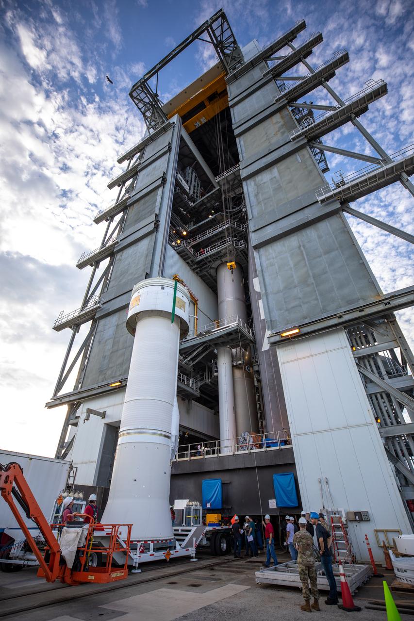
A Centaur upper stage arrives at the Space Launch Complex 41 Vertical Integration Facility at Florida’s Cape Canaveral Air Force Station on Nov. 8, 2019, for mating to the United Launch Alliance Atlas V first stage in preparation for Boeing’s Orbital Flight Test (OFT). The uncrewed OFT mission will rendezvous and dock Boeing’s CST-100 Starliner spacecraft with the International Space Station as part of NASA’s Commercial Crew Program. Starliner will launch atop the Atlas V rocket from Space Launch Complex 41.
The United Launch Alliance Atlas V first stage is lifted to the vertical position on Nov. 4, 2019, in the Vertical Integration Facility at Space Launch Complex 41 at Cape Canaveral Air Force Station in Florida, in preparation for Boeing’s Orbital Flight Test (OFT). The uncrewed OFT mission will rendezvous and dock Boeing’s CST-100 Starliner spacecraft with the International Space Station as part of NASA’s Commercial Crew Program. Starliner will launch atop the Atlas V rocket from Space Launch Complex 41.
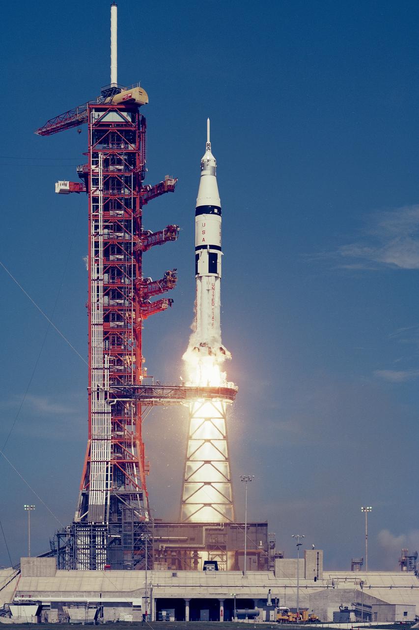
CAPE CANAVERAL, Fla. – The Apollo Soyuz Test Project Saturn IB launch vehicle thundered away from KSC’s Launch Complex 39B at 3:50 p.m. today. Aboard the Apollo Command Module were ASTP Astronauts Thomas Stafford, Vance Brand and Donald Slayton. The astronauts will rendezvous and dock with a Soyuz spacecraft, launched this morning from the Baikonur launch facility in the Soviet Union, carrying Soviet cosmonauts Aleksey Leonov and Valeriy Kubasov. The first international crewed spaceflight was a joint U.S.-U.S.S.R. rendezvous and docking mission. The Apollo-Soyuz Test Project, or ASTP, took its name from the spacecraft employed: the American Apollo and the Soviet Soyuz. The three-man Apollo crew lifted off from Kennedy Space Center aboard a Saturn IB rocket on July 15, 1975, to link up with the Soyuz that had launched a few hours earlier. A cylindrical docking module served as an airlock between the two spacecraft for transfer of the crew members. Photo credit: NASA
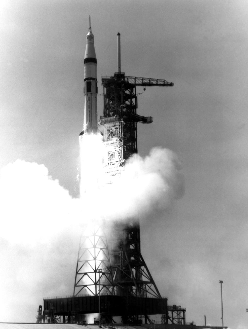
KENNEDY SPACE CENTER, FLA. -- The Apollo Soyuz Test Project Saturn IB launch vehicle thundered away from KSC's Launch Complex 39B at 3:50 p.m. today. Aboard the Apollo Command Module were ASTP astronauts Thomas Stafford, Vance Brand and Donald Slayton. The astronauts will rendezvous and dock with a Soyuz spacecraft, launched this morning from the Baykonur launch facility in the Soviet Union, carrying Soviet cosmonauts Aleksey Leonov and Valeriy Kubasov. The ASTP launches mark the first time that manned spacecraft of two nations have met in space for joint engineering and scientific investigations.
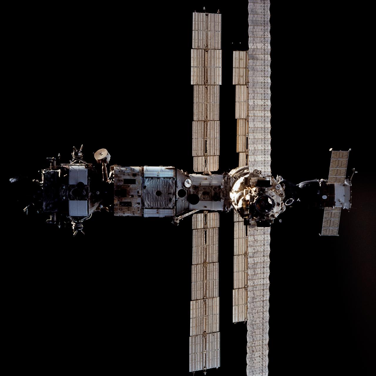
STS063-712-017 (6 Feb. 1995) --- Russia's Mir Space Station during rendezvous operations with the Space Shuttle Discovery. Docked at the bottom of the Mir facility is a Soyuz spacecraft. On the opposite end (almost cropped out of frame at top) is a Progress spacecraft. Onboard the Space Shuttle Discovery were astronauts James D. Wetherbee, mission commander; Eileen M. Collins, pilot; Bernard A. Harris, Jr., payload commander; C. Michael Foale and Janice E. Voss, mission specialists; along with cosmonaut Vladimir G. Titov, mission specialist.
A Centaur upper stage is moved into position above the United Launch Alliance Atlas V first stage inside the Space Launch Complex 41 Vertical Integration Facility at Florida’s Cape Canaveral Air Force Station on Nov. 8, 2019, in preparation for Boeing’s Orbital Flight Test (OFT). The uncrewed OFT mission will rendezvous and dock Boeing’s CST-100 Starliner spacecraft with the International Space Station as part of NASA’s Commercial Crew Program. Starliner will launch atop the Atlas V rocket from Space Launch Complex 41.
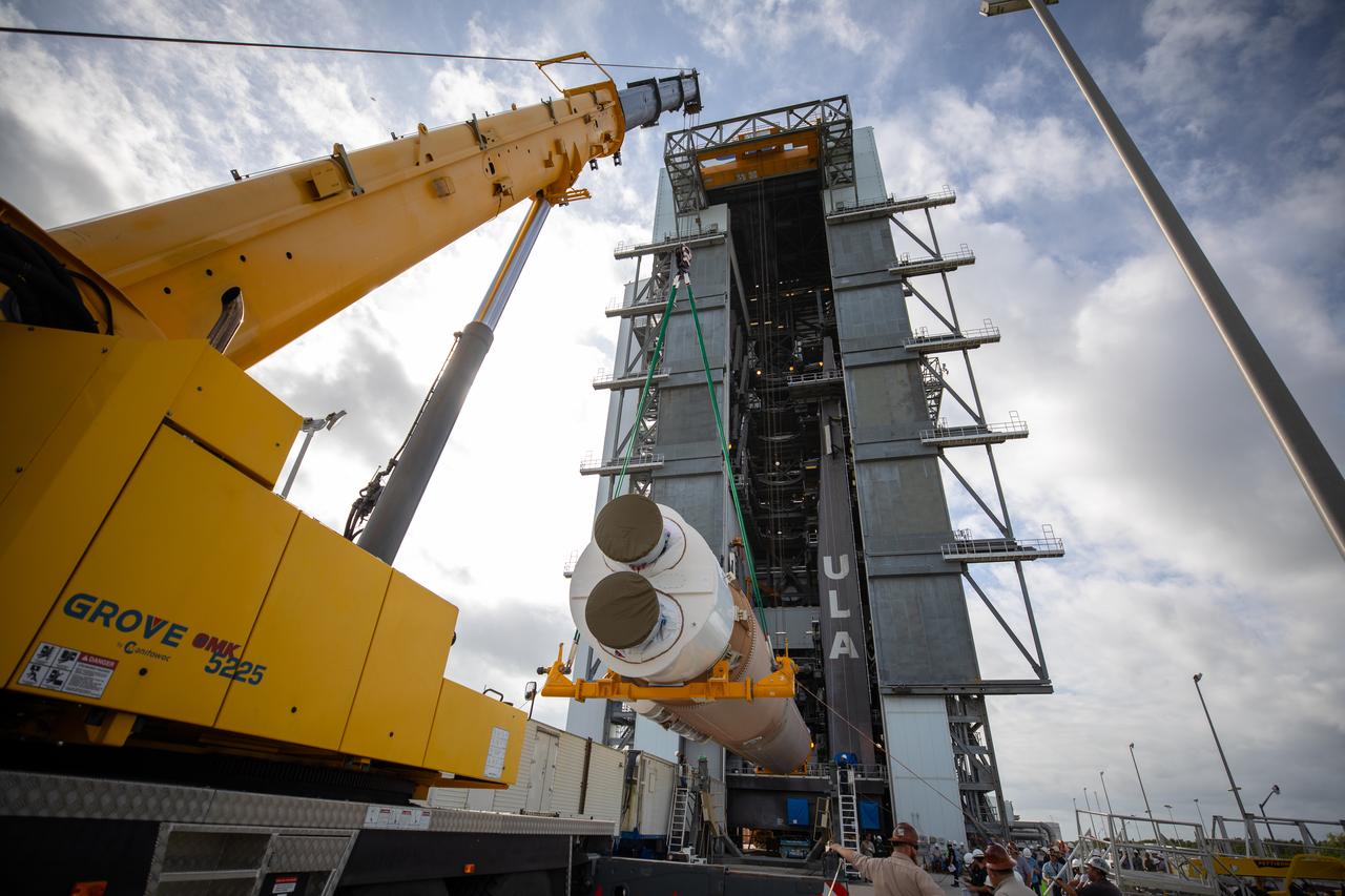
Two solid rocket boosters are delivered to the Space Launch Complex 41 Vertical Integration Facility at Cape Canaveral Air Force Station in Florida on Nov. 7, 2019. The boosters were then mated to the United Launch Alliance Atlas V first stage in preparation for Boeing’s Orbital Flight Test (OFT). The uncrewed OFT mission will rendezvous and dock Boeing’s CST-100 Starliner spacecraft with the International Space Station as part of NASA’s Commercial Crew Program. Starliner will launch atop the Atlas V rocket from Space Launch Complex 41.
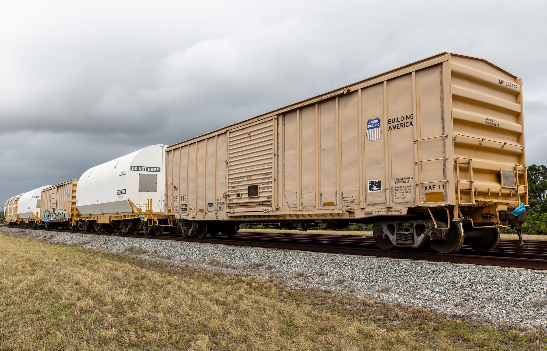
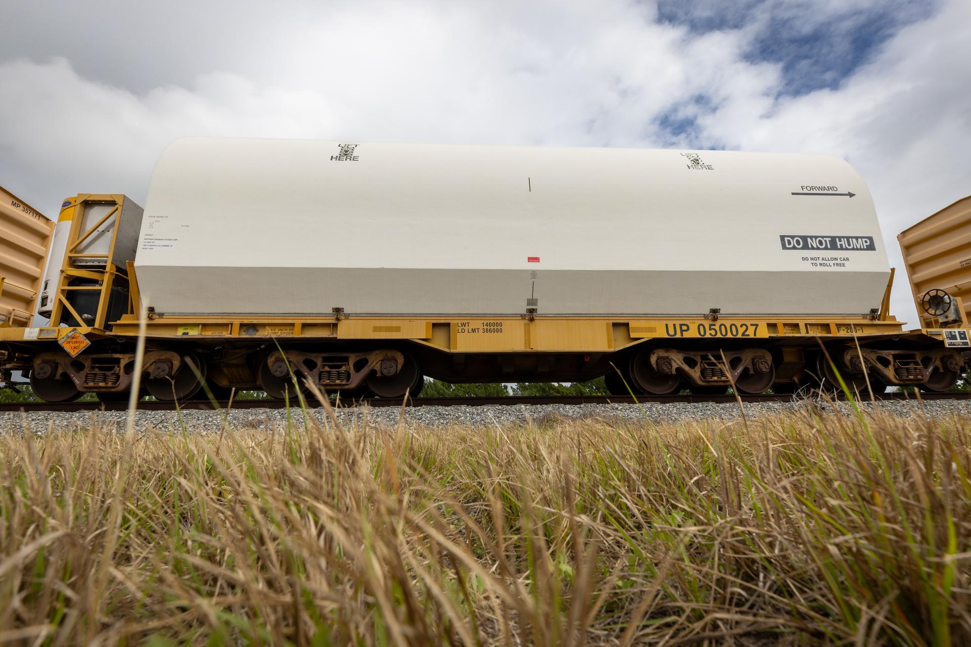
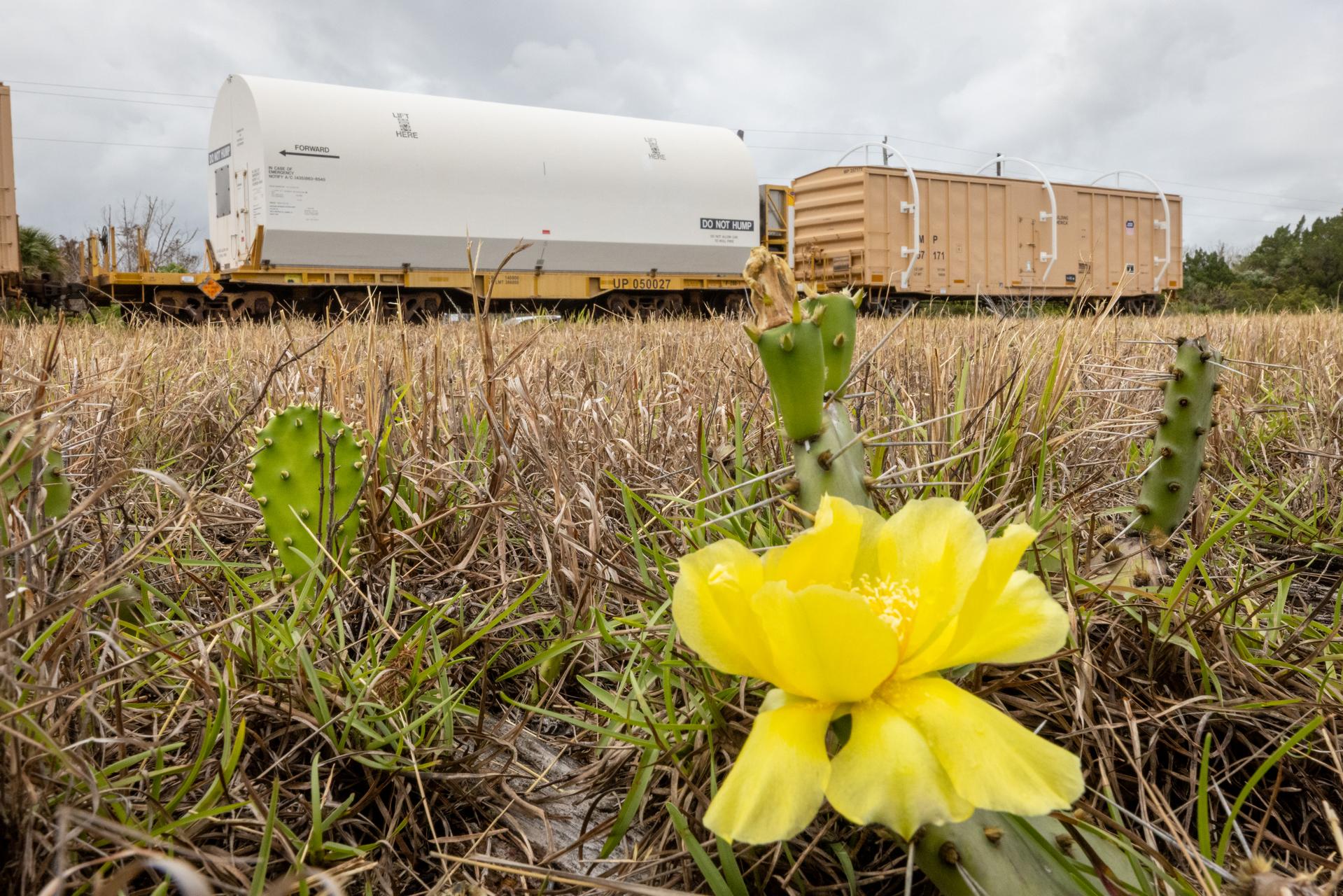
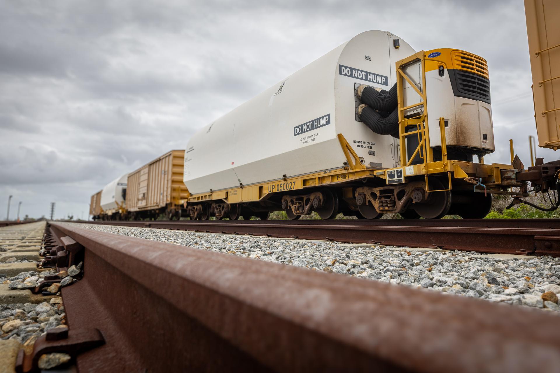
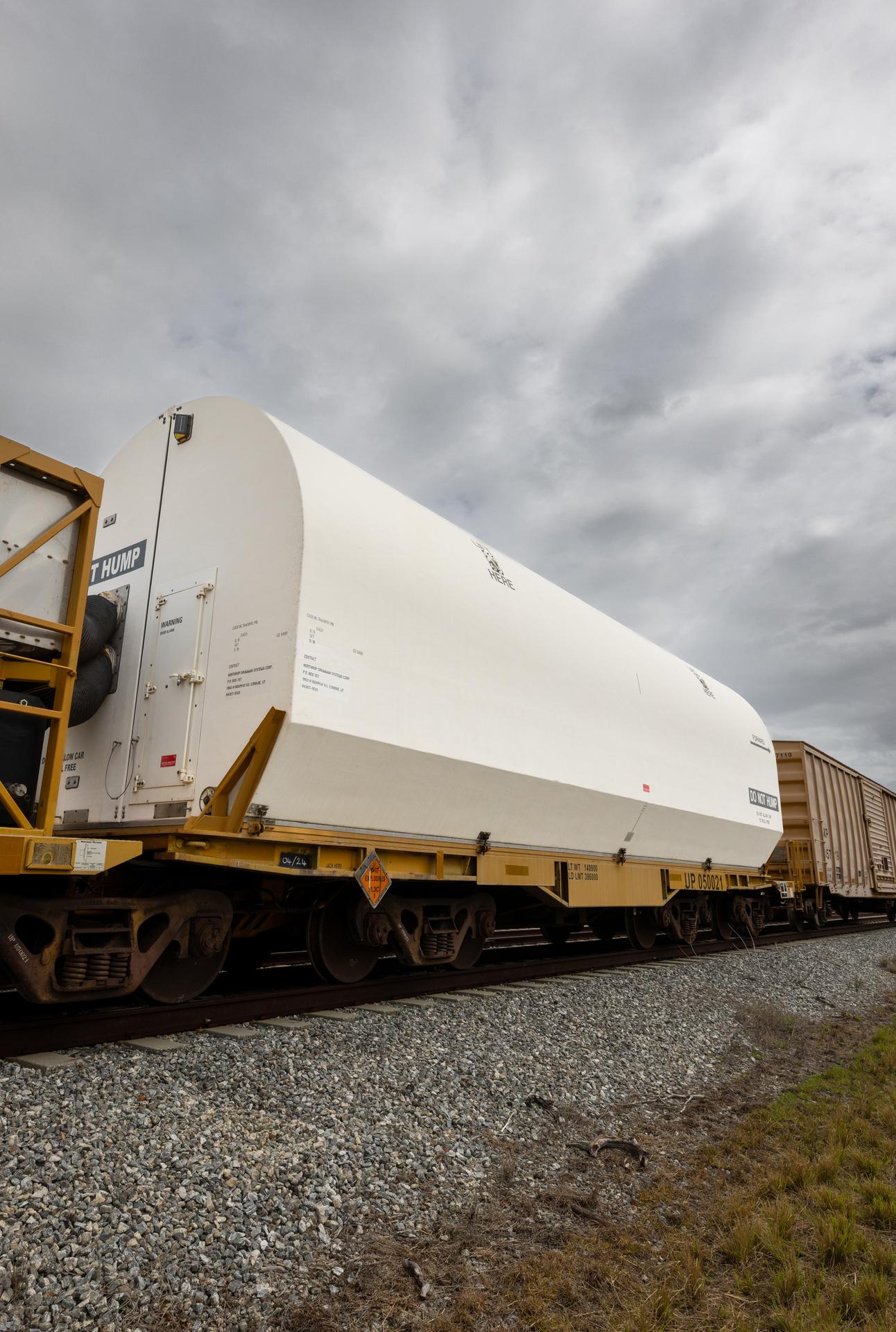
The solid rocket booster aft skirt segments for NASA’s Artemis III SLS (Space Launch System) rocket arrive at a rail yard near the agency’s Kennedy Space Center in Florida on Wednesday, April 8, 2026. Comprising the bottom of the rocket’s twin, five-segment solid rocket boosters, the aft skirt segments traveled by train in specialized transporters to the Florida spaceport and will be transferred from the rail yard to NASA Kennedy’s Rotation, Processing and Surge Facility for processing. The Artemis III mission will launch crew in the Orion spacecraft on top of the SLS rocket to test rendezvous and docking capabilities between Orion and commercial spacecraft needed to land astronauts on the Moon.
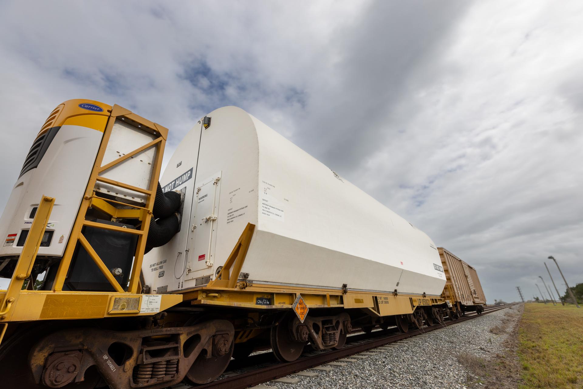
The solid rocket booster aft skirt segments for NASA’s Artemis III SLS (Space Launch System) rocket arrive at a rail yard near the agency’s Kennedy Space Center in Florida on Wednesday, April 8, 2026. Comprising the bottom of the rocket’s twin, five-segment solid rocket boosters, the aft skirt segments traveled by train in specialized transporters to the Florida spaceport and will be transferred from the rail yard to NASA Kennedy’s Rotation, Processing and Surge Facility for processing. The Artemis III mission will launch crew in the Orion spacecraft on top of the SLS rocket to test rendezvous and docking capabilities between Orion and commercial spacecraft needed to land astronauts on the Moon.
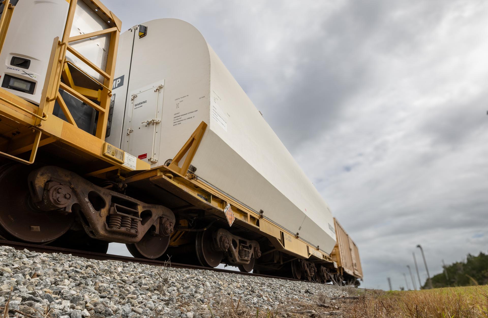
The solid rocket booster aft skirt segments for NASA’s Artemis III SLS (Space Launch System) rocket arrive at a rail yard near the agency’s Kennedy Space Center in Florida on Wednesday, April 8, 2026. Comprising the bottom of the rocket’s twin, five-segment solid rocket boosters, the aft skirt segments traveled by train in specialized transporters to the Florida spaceport and will be transferred from the rail yard to NASA Kennedy’s Rotation, Processing and Surge Facility for processing. The Artemis III mission will launch crew in the Orion spacecraft on top of the SLS rocket to test rendezvous and docking capabilities between Orion and commercial spacecraft needed to land astronauts on the Moon.
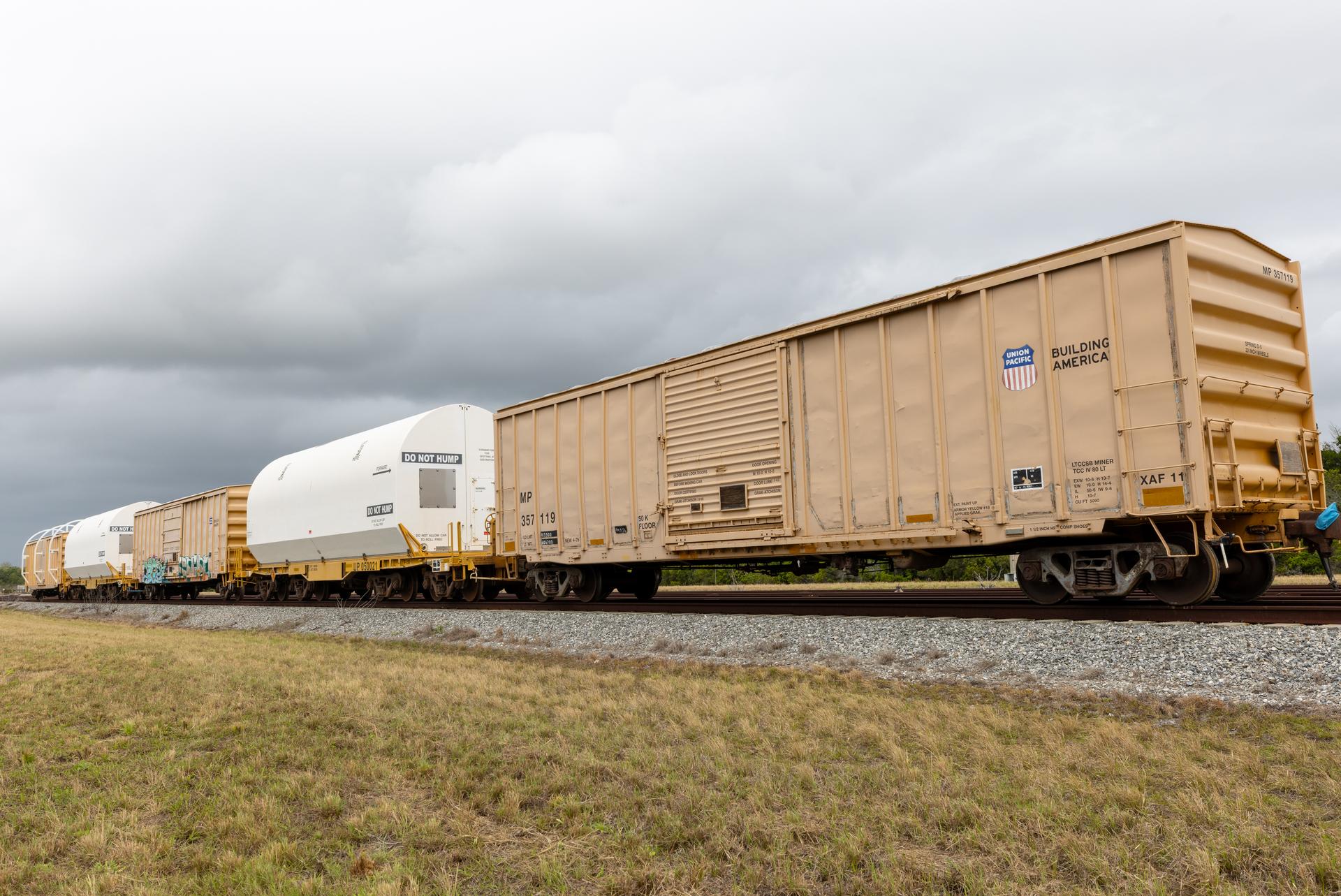
The solid rocket booster aft skirt segments for NASA’s Artemis III SLS (Space Launch System) rocket arrive at a rail yard near the agency’s Kennedy Space Center in Florida on Wednesday, April 8, 2026. Comprising the bottom of the rocket’s twin, five-segment solid rocket boosters, the aft skirt segments traveled by train in specialized transporters to the Florida spaceport and will be transferred from the rail yard to NASA Kennedy’s Rotation, Processing and Surge Facility for processing. The Artemis III mission will launch crew in the Orion spacecraft on top of the SLS rocket to test rendezvous and docking capabilities between Orion and commercial spacecraft needed to land astronauts on the Moon.
The solid rocket booster aft skirt segments for NASA’s Artemis III SLS (Space Launch System) rocket arrive at a rail yard near the agency’s Kennedy Space Center in Florida on Wednesday, April 8, 2026. Comprising the bottom of the rocket’s twin, five-segment solid rocket boosters, the aft skirt segments traveled by train in specialized transporters to the Florida spaceport and will be transferred from the rail yard to NASA Kennedy’s Rotation, Processing and Surge Facility for processing. The Artemis III mission will launch crew in the Orion spacecraft on top of the SLS rocket to test rendezvous and docking capabilities between Orion and commercial spacecraft needed to land astronauts on the Moon.
The solid rocket booster aft skirt segments for NASA’s Artemis III SLS (Space Launch System) rocket arrive at a rail yard near the agency’s Kennedy Space Center in Florida on Wednesday, April 8, 2026. Comprising the bottom of the rocket’s twin, five-segment solid rocket boosters, the aft skirt segments traveled by train in specialized transporters to the Florida spaceport and will be transferred from the rail yard to NASA Kennedy’s Rotation, Processing and Surge Facility for processing. The Artemis III mission will launch crew in the Orion spacecraft on top of the SLS rocket to test rendezvous and docking capabilities between Orion and commercial spacecraft needed to land astronauts on the Moon.
The solid rocket booster aft skirt segments for NASA’s Artemis III SLS (Space Launch System) rocket arrive at a rail yard near the agency’s Kennedy Space Center in Florida on Wednesday, April 8, 2026. Comprising the bottom of the rocket’s twin, five-segment solid rocket boosters, the aft skirt segments traveled by train in specialized transporters to the Florida spaceport and will be transferred from the rail yard to NASA Kennedy’s Rotation, Processing and Surge Facility for processing. The Artemis III mission will launch crew in the Orion spacecraft on top of the SLS rocket to test rendezvous and docking capabilities between Orion and commercial spacecraft needed to land astronauts on the Moon.
The solid rocket booster aft skirt segments for NASA’s Artemis III SLS (Space Launch System) rocket arrive at a rail yard near the agency’s Kennedy Space Center in Florida on Wednesday, April 8, 2026. Comprising the bottom of the rocket’s twin, five-segment solid rocket boosters, the aft skirt segments traveled by train in specialized transporters to the Florida spaceport and will be transferred from the rail yard to NASA Kennedy’s Rotation, Processing and Surge Facility for processing. The Artemis III mission will launch crew in the Orion spacecraft on top of the SLS rocket to test rendezvous and docking capabilities between Orion and commercial spacecraft needed to land astronauts on the Moon.
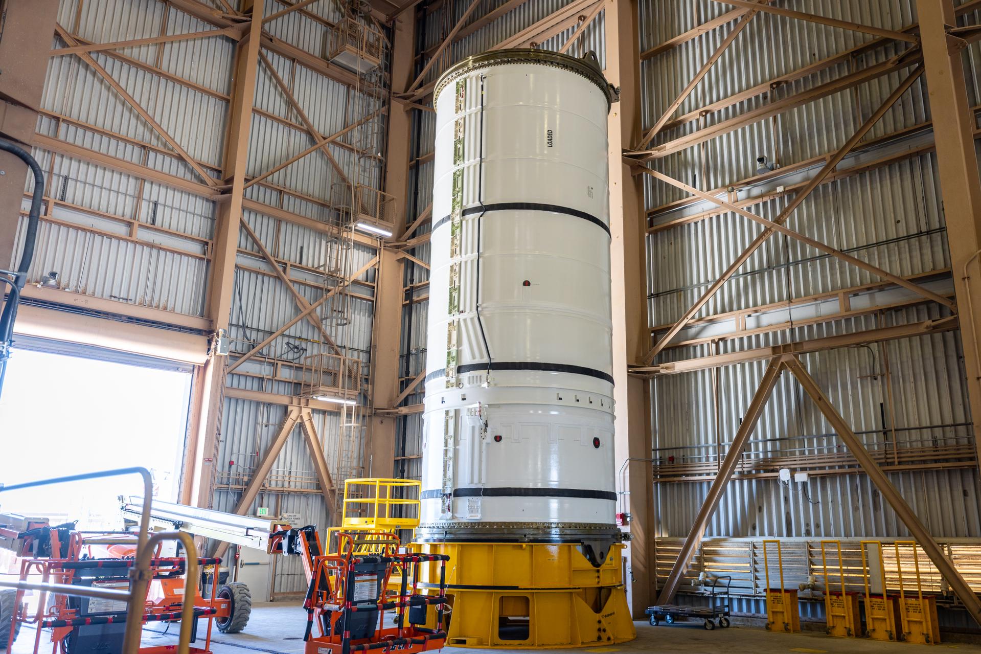
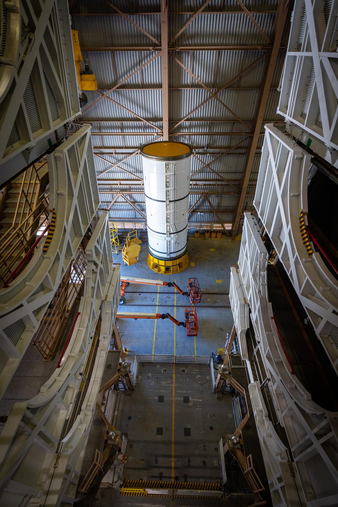
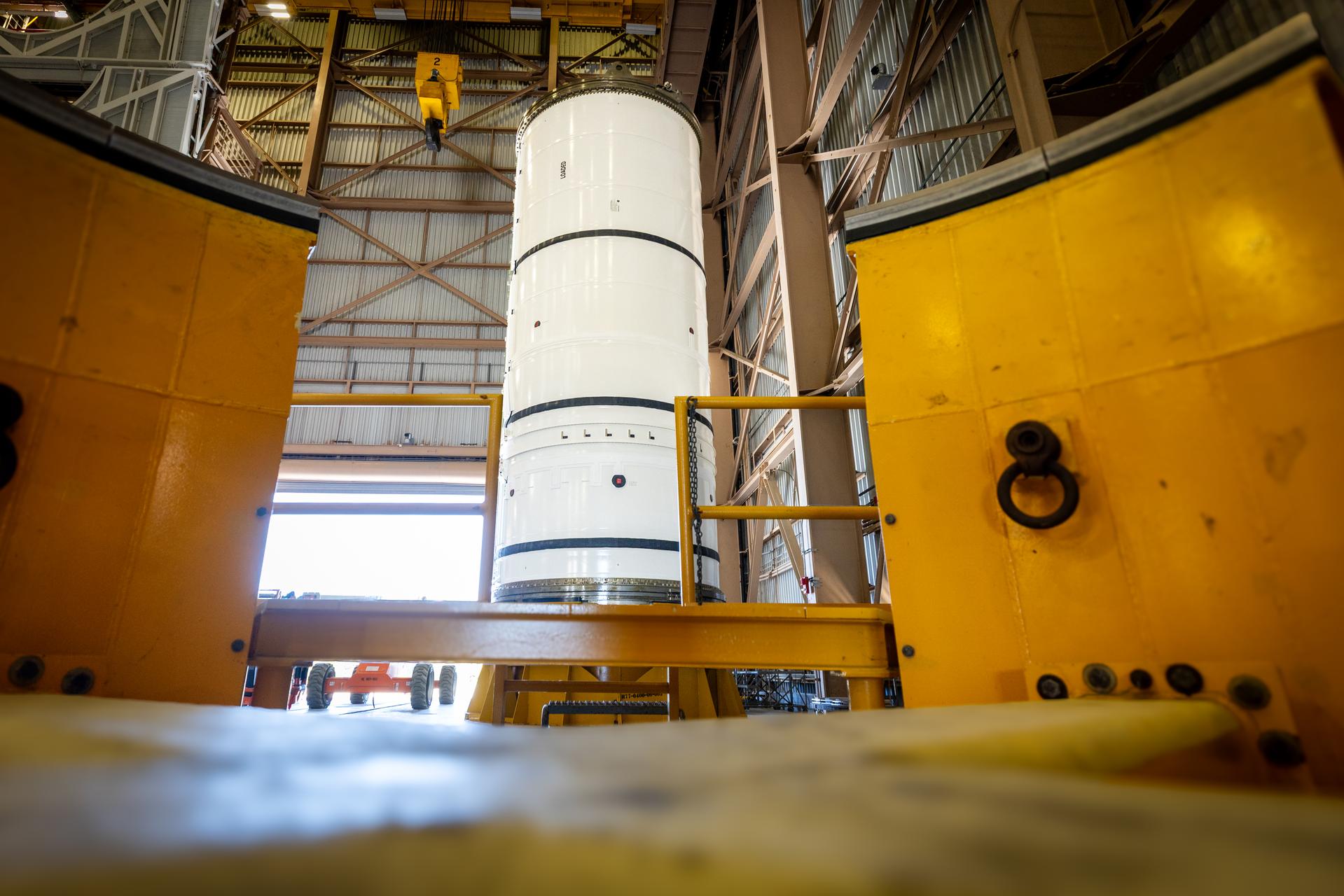
The left-hand forward solid rocket booster segment for NASA’s Artemis III SLS (Space Launch System) rocket is removed from its shipping container ahead of processing inside the Rotation, Processing and Surge Facility at the agency’s Kennedy Space Center in Florida on Wednesday, April 15, 2026. The SLS rocket’s twin boosters, manufactured by Northrop Grumman in Utah, will provide more than 75 percent of the SLS rocket’s total thrust at launch. The Artemis III mission will launch crew in the Orion spacecraft on top of the SLS rocket to test rendezvous and docking capabilities between Orion and commercial spacecraft needed to land astronauts on the Moon.
The left-hand forward solid rocket booster segment for NASA’s Artemis III SLS (Space Launch System) rocket is removed from its shipping container ahead of processing inside the Rotation, Processing and Surge Facility at the agency’s Kennedy Space Center in Florida on Wednesday, April 15, 2026. The SLS rocket’s twin boosters, manufactured by Northrop Grumman in Utah, will provide more than 75 percent of the SLS rocket’s total thrust at launch. The Artemis III mission will launch crew in the Orion spacecraft on top of the SLS rocket to test rendezvous and docking capabilities between Orion and commercial spacecraft needed to land astronauts on the Moon.
The left-hand forward solid rocket booster segment for NASA’s Artemis III SLS (Space Launch System) rocket is removed from its shipping container ahead of processing inside the Rotation, Processing and Surge Facility at the agency’s Kennedy Space Center in Florida on Wednesday, April 15, 2026. The SLS rocket’s twin boosters, manufactured by Northrop Grumman in Utah, will provide more than 75 percent of the SLS rocket’s total thrust at launch. The Artemis III mission will launch crew in the Orion spacecraft on top of the SLS rocket to test rendezvous and docking capabilities between Orion and commercial spacecraft needed to land astronauts on the Moon.
The left-hand forward solid rocket booster segment for NASA’s Artemis III SLS (Space Launch System) rocket is removed from its shipping container ahead of processing inside the Rotation, Processing and Surge Facility at the agency’s Kennedy Space Center in Florida on Wednesday, April 15, 2026. The SLS rocket’s twin boosters, manufactured by Northrop Grumman in Utah, will provide more than 75 percent of the SLS rocket’s total thrust at launch. The Artemis III mission will launch crew in the Orion spacecraft on top of the SLS rocket to test rendezvous and docking capabilities between Orion and commercial spacecraft needed to land astronauts on the Moon.
The left-hand forward solid rocket booster segment for NASA’s Artemis III SLS (Space Launch System) rocket is removed from its shipping container ahead of processing inside the Rotation, Processing and Surge Facility at the agency’s Kennedy Space Center in Florida on Wednesday, April 15, 2026. The SLS rocket’s twin boosters, manufactured by Northrop Grumman in Utah, will provide more than 75 percent of the SLS rocket’s total thrust at launch. The Artemis III mission will launch crew in the Orion spacecraft on top of the SLS rocket to test rendezvous and docking capabilities between Orion and commercial spacecraft needed to land astronauts on the Moon.
The left-hand forward solid rocket booster segment for NASA’s Artemis III SLS (Space Launch System) rocket is removed from its shipping container ahead of processing inside the Rotation, Processing and Surge Facility at the agency’s Kennedy Space Center in Florida on Wednesday, April 15, 2026. The SLS rocket’s twin boosters, manufactured by Northrop Grumman in Utah, will provide more than 75 percent of the SLS rocket’s total thrust at launch. The Artemis III mission will launch crew in the Orion spacecraft on top of the SLS rocket to test rendezvous and docking capabilities between Orion and commercial spacecraft needed to land astronauts on the Moon.
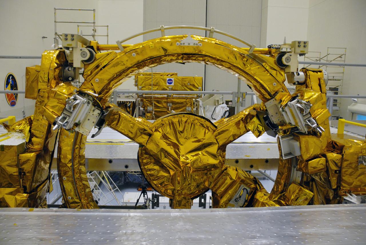
CAPE CANAVERAL, Fla. – In the high bay of the Payload Hazardous Servicing Facility at NASA's Kennedy Space Center, three of four carriers supporting the space shuttle Atlantis STS-125 Hubble Space Telescope servicing mission have been unwrapped for final launch processing. The Super Lightweight Interchangeable Carrier and the Orbital Replacement Unit Carrier can be seen through the distinctive soft capture mechanism, or SCM, of the Flight Support System. The SCM will be permanently attached to Hubble’s aft shroud by spacewalking astronauts and will provide a rendezvous and docking target that can be easily seen and recognized by a docking vehicle. The Multi-Use Lightweight Equipment carrier will be delivered in early August. The carriers will be prepared for the integration of telescope science instruments, both internal and external replacement components, as well as the flight support equipment to be used by the astronauts during the Hubble servicing mission, targeted for launch Oct. 8. Photo credit: NASA/Jack Pfaller
CAPE CANAVERAL, Fla. – KSC Director Lee Scherer, left, escorts a Soviet interpreter and Vladimir Shatalov, Soviet Cosmonaut Training Chief, on a tour of Pad 39B at the Spaceport. The Soviet and American personnel connected with July's Apollo Soyuz Test Project were at KSC February 8-10 to inspect equipment and tour facilities. The first international crewed spaceflight was a joint U.S.-U.S.S.R. rendezvous and docking mission. The Apollo-Soyuz Test Project, or ASTP, took its name from the spacecraft employed: the American Apollo and the Soviet Soyuz. The three-man Apollo crew lifted off from Kennedy Space Center aboard a Saturn IB rocket on July 15, 1975, to link up with the Soyuz that had launched a few hours earlier. A cylindrical docking module served as an airlock between the two spacecraft for transfer of the crew members. Photo credit: NASA
![CAPE CANAVERAL, Fla. – The Soviet and American crews for the July Apollo Soyuz Test Project [standing, center] addressed personnel assembled in a firing room at KSC on February 10. The crews for the joint manned space mission toured the Center during their three-day visit which also included inspection of ASTP equipment and facilities and a trip to Disney World. The first international crewed spaceflight was a joint U.S.-U.S.S.R. rendezvous and docking mission. The Apollo-Soyuz Test Project, or ASTP, took its name from the spacecraft employed: the American Apollo and the Soviet Soyuz. The three-man Apollo crew lifted off from Kennedy Space Center aboard a Saturn IB rocket on July 15, 1975, to link up with the Soyuz that had launched a few hours earlier. A cylindrical docking module served as an airlock between the two spacecraft for transfer of the crew members. Photo credit: NASA](https://images-assets.nasa.gov/image/KSC-108-75P-0057/KSC-108-75P-0057~medium.jpg)
CAPE CANAVERAL, Fla. – The Soviet and American crews for the July Apollo Soyuz Test Project [standing, center] addressed personnel assembled in a firing room at KSC on February 10. The crews for the joint manned space mission toured the Center during their three-day visit which also included inspection of ASTP equipment and facilities and a trip to Disney World. The first international crewed spaceflight was a joint U.S.-U.S.S.R. rendezvous and docking mission. The Apollo-Soyuz Test Project, or ASTP, took its name from the spacecraft employed: the American Apollo and the Soviet Soyuz. The three-man Apollo crew lifted off from Kennedy Space Center aboard a Saturn IB rocket on July 15, 1975, to link up with the Soyuz that had launched a few hours earlier. A cylindrical docking module served as an airlock between the two spacecraft for transfer of the crew members. Photo credit: NASA
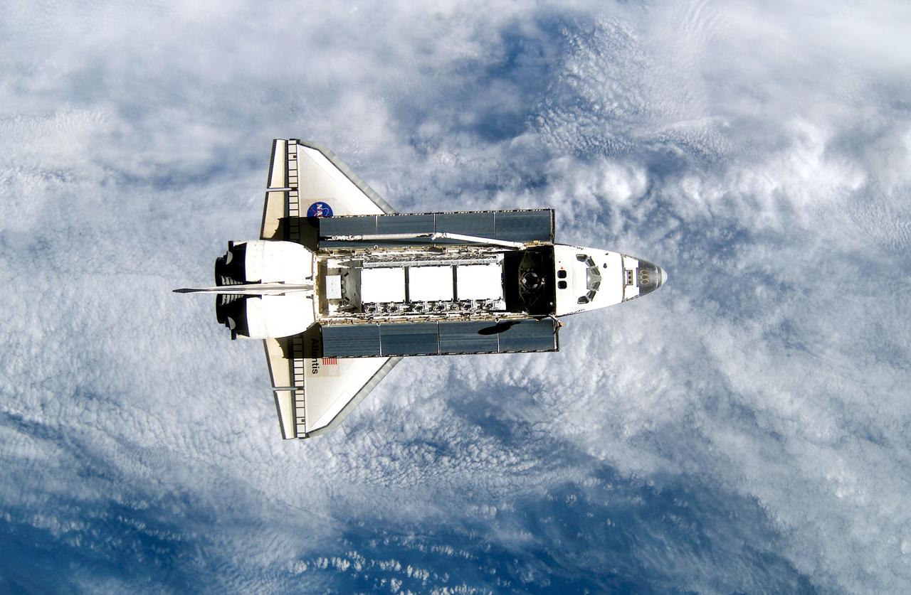
Back dropped against a blue and white Earth, the Space Shuttle Orbiter Atlantis was photographed by an Expedition 5 crew member onboard the International Space Station (ISS) during rendezvous and docking operations. Docking occurred at 10:17 am on October 9, 2002. The Starboard 1 (S1) Integrated Truss Structure, the primary payload of the STS-112 mission, can be seen in Atlantis' cargo bay. Installed and outfitted within 3 sessions of Extravehicular Activity (EVA) during the 11 day mission, the S1 truss provides structural support for the orbiting research facility's radiator panels, which use ammonia to cool the Station's complex power system. The S1 truss, attached to the S0 (S Zero) truss installed by the previous STS-110 mission, flows 637 pounds of anhydrous ammonia through three heat rejection radiators.
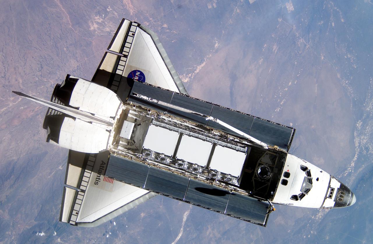
Back dropped against a blue and white Earth, the Space Shuttle Orbiter Atlantis was photographed by an Expedition 5 crew member onboard the International Space Station (ISS) during rendezvous and docking operations. Docking occurred at 10:17 am on October 9, 2002. The Starboard 1 (S1) Integrated Truss Structure, the primary payload of the STS-112 mission, can be seen in Atlantis' cargo bay. Installed and outfitted within 3 sessions of Extravehicular Activity (EVA) during the 11 day mission, the S1 truss provides structural support for the orbiting research facility's radiator panels, which use ammonia to cool the Station's complex power system. The S1 truss, attached to the S0 (S Zero) truss installed by the previous STS-110 mission, flows 637 pounds of anhydrous ammonia through three heat rejection radiators.

CAPE CANAVERAL, Fla. – Soviet Apollo Soyuz Test Project prime crew member Valeriy Kubasov inspects equipment inside the Apollo Command Module. The Soviet and American ASTP crews were at KSC February 8-10 to tour facilities and inspect equipment in preparation for the mid-July joint mission. The first international crewed spaceflight was a joint U.S.-U.S.S.R. rendezvous and docking mission. The Apollo-Soyuz Test Project, or ASTP, took its name from the spacecraft employed: the American Apollo and the Soviet Soyuz. The three-man Apollo crew lifted off from Kennedy Space Center aboard a Saturn IB rocket on July 15, 1975, to link up with the Soyuz that had launched a few hours earlier. A cylindrical docking module served as an airlock between the two spacecraft for transfer of the crew members. Photo credit: NASA
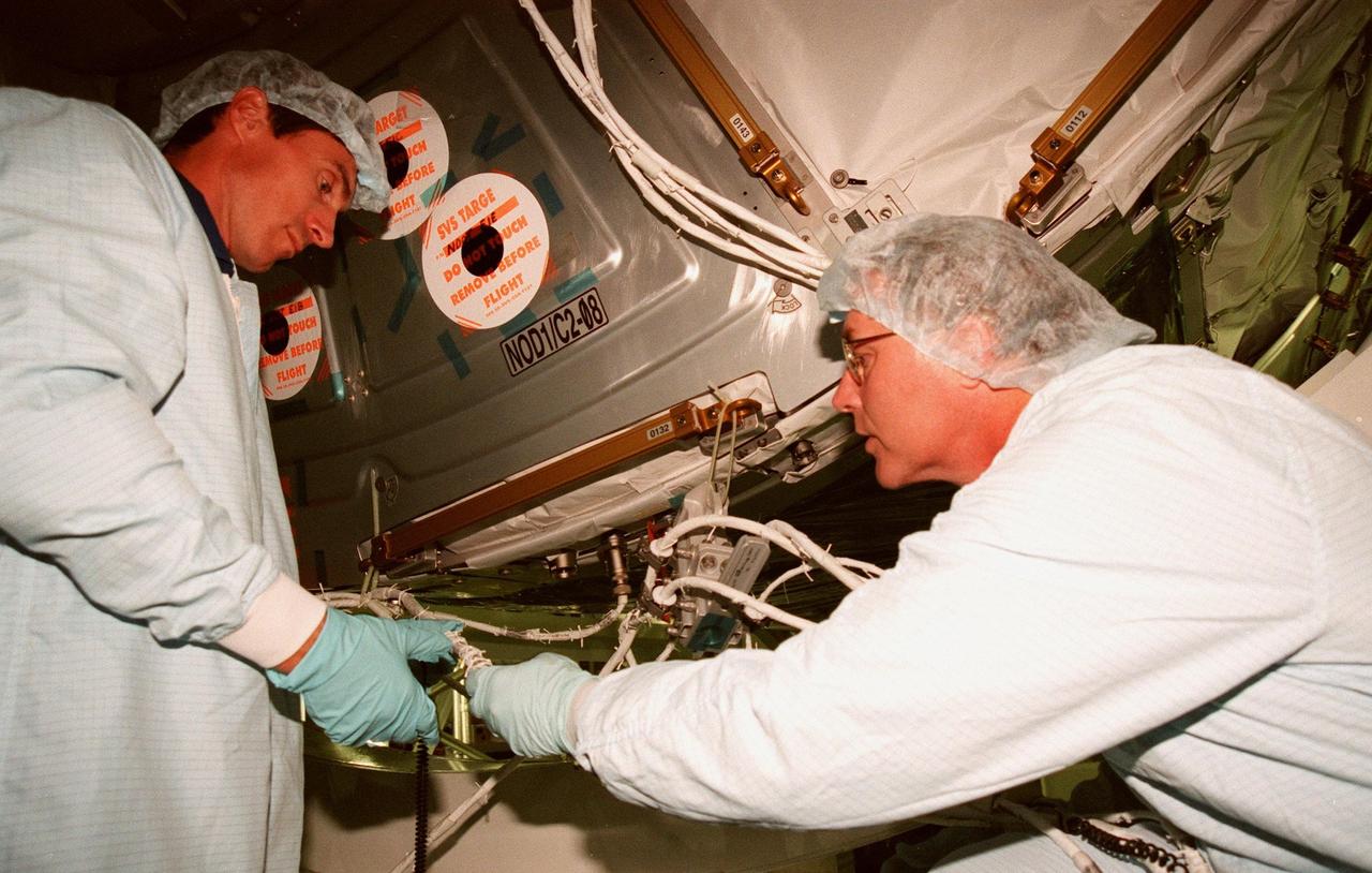
KENNEDY SPACE CENTER, FLA. -- In the Space Station Processing Facility, STS-88 Mission Specialists Sergei Krikalev, a Russian cosmonaut, and Jerry L. Ross check out equipment on the Unity connecting module, primary payload on the mission. The STS-88 crew members are participating in a Crew Equipment Interface Test (CEIT), familiarizing themselves with the orbiter's midbody and crew compartments. Scheduled for launch on Dec. 3, 1998, STS-88 will be the first Space Shuttle launch for the International Space Station. The Unity connecting module will be mated to the Russian-built Zarya control module, already on orbit after a November launch. Unity will have two Pressurized Mating Adapters (PMAs) attached and 1 stowage rack installed inside. PMA-1 will connect U.S. and Russian elements; PMA-2 will provide a Shuttle docking location. Eventually, Unity's six ports will provide connecting points for the Z1 truss exterior framework, U.S. lab, airlock, cupola, Node 3, and the Multi-Purpose Logistics Module, as well as the control module. Zarya is a self-supporting active vehicle, providing propulsive control capability and power through the early assembly stages. It provides fuel storage capability and a rendezvous and docking capability to the Service Module
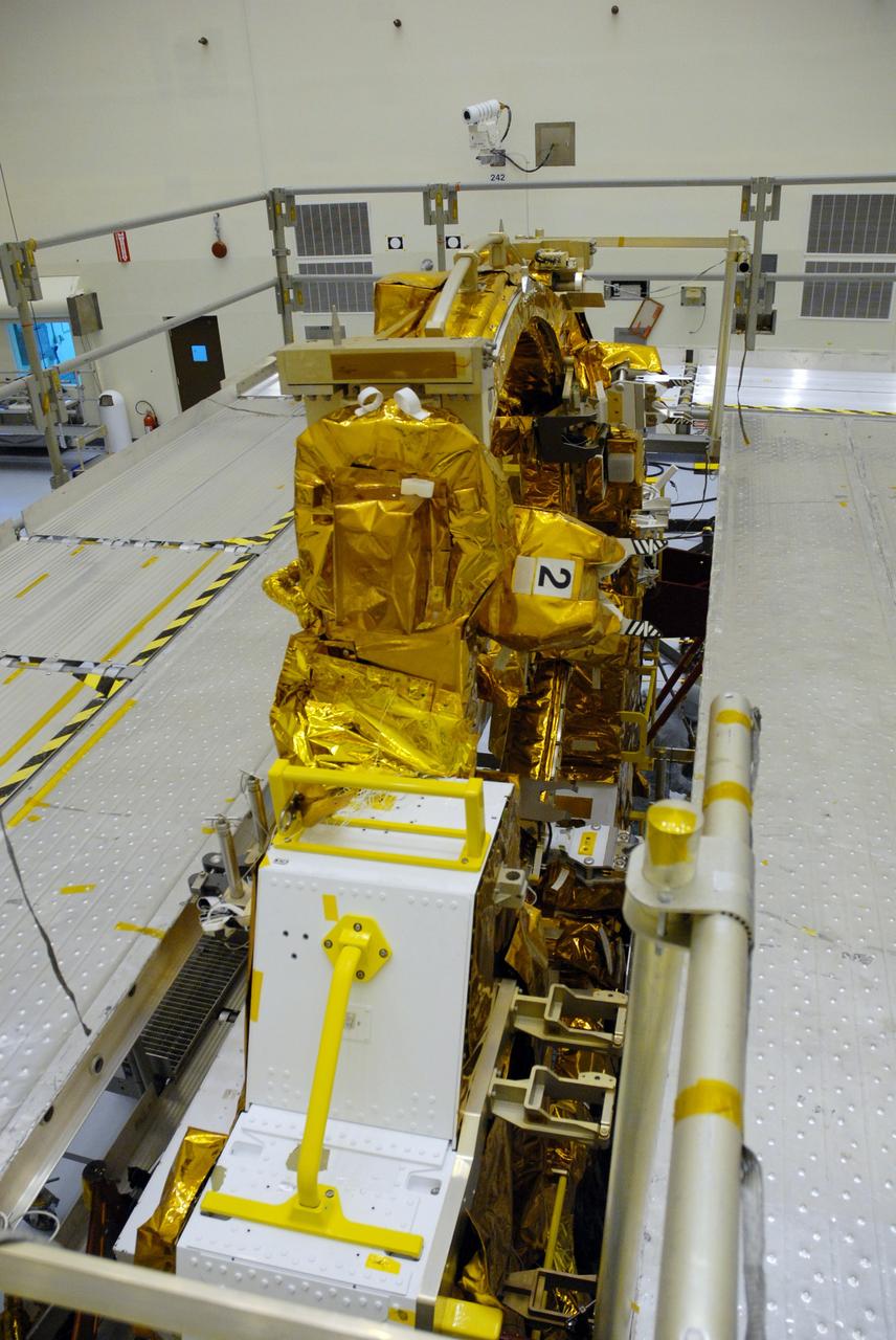
CAPE CANAVERAL, Fla. – In the high bay of the Payload Hazardous Servicing Facility at NASA's Kennedy Space Center, the protective wrapping has been removed from the Flight Support System for the Hubble Space Telescope revealing the soft capture mechanism , or SCM. The SCM will be permanently attached to Hubble’s aft shroud by spacewalking astronauts and will provide a rendezvous and docking target that can be easily seen and recognized by a docking vehicle. The Flight Support System, or FSS, is one of four carriers supporting hardware for space shuttle Atlantis' STS-125 mission to service the telescope. The Super Lightweight Interchangeable Carrier, or SLIC, and the Orbital Replacement Unit Carrier, or ORUC, have also arrived at Kennedy. The Multi-Use Lightweight Equipment carrier will be delivered in early August. The carriers will be prepared for the integration of telescope science instruments, both internal and external replacement components, as well as the flight support equipment to be used by the astronauts during the Hubble servicing mission, targeted for launch Oct. 8. Photo credit: NASA/Jack Pfaller
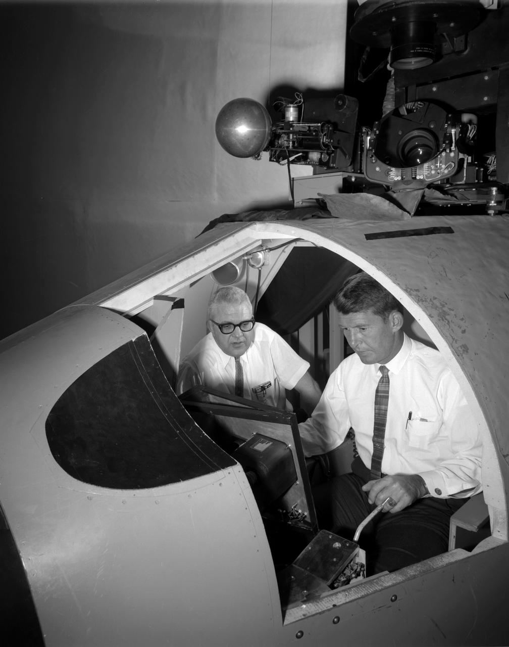
![Astronaut Charles Conrad at the controls of the Visual Docking Simulator. From A.W. Vogeley, "Piloted Space-Flight Simulation at Langley Research Center," paper presented at the American Society of Mechanical Engineers 1966 Winter Meeting, New York, NY, November 27-December 1, 1966. "This facility was [later known as the Visual-Optical Simulator.] It presents to the pilot an out-the-window view of his target in correct 6 degrees of freedom motion. The scene is obtained by a television camera pick-up viewing a small-scale gimbaled model of the target." "For docking studies, the docking target picture was projected onto the surface of a 20-foot-diameter sphere and the pilot could, effectively, maneuver into contract. this facility was used in a comparison study with the Rendezvous Docking Simulator - one of the few comparison experiments in which conditions were carefully controlled and a reasonable sample of pilots used. All pilots preferred the more realistic RDS visual scene. The pilots generally liked the RDS angular motion cues although some objected to the false gravity cues that these motions introduced. Training time was shorter on the RDS, but final performance on both simulators was essentially equal. " "For station-keeping studies, since close approach is not required, the target was presented to the pilot through a virtual-image system which projects his view to infinity, providing a more realistic effect. In addition to the target, the system also projects a star and horizon background. "](https://images-assets.nasa.gov/image/LRC-1963-B701_P-09519/LRC-1963-B701_P-09519~medium.jpg)
Astronaut Charles Conrad at the controls of the Visual Docking Simulator. From A.W. Vogeley, "Piloted Space-Flight Simulation at Langley Research Center," paper presented at the American Society of Mechanical Engineers 1966 Winter Meeting, New York, NY, November 27-December 1, 1966. "This facility was [later known as the Visual-Optical Simulator.] It presents to the pilot an out-the-window view of his target in correct 6 degrees of freedom motion. The scene is obtained by a television camera pick-up viewing a small-scale gimbaled model of the target." "For docking studies, the docking target picture was projected onto the surface of a 20-foot-diameter sphere and the pilot could, effectively, maneuver into contract. this facility was used in a comparison study with the Rendezvous Docking Simulator - one of the few comparison experiments in which conditions were carefully controlled and a reasonable sample of pilots used. All pilots preferred the more realistic RDS visual scene. The pilots generally liked the RDS angular motion cues although some objected to the false gravity cues that these motions introduced. Training time was shorter on the RDS, but final performance on both simulators was essentially equal. " "For station-keeping studies, since close approach is not required, the target was presented to the pilot through a virtual-image system which projects his view to infinity, providing a more realistic effect. In addition to the target, the system also projects a star and horizon background. "
Walter (Wally) M. Schirra in Visual Docking Simulator From A.W. Vogeley, "Piloted Space-Flight Simulation at Langley Research Center," Paper presented at the American Society of Mechanical Engineers 1966 Winter Meeting, New York, NY, November 27-December 1, 1966. "This facility was [later known as the Visual-Optical Simulator. It presents to the pilot an out-the-window view of his target in correct 6 degrees of freedom motion. The scene is obtained by a television camera pick-up viewing a small-scale gimbaled model of the target. "For docking studies, the docking target picture was projected onto the surface of a 20-foot-diameter sphere and the pilot could, effectively, maneuver into contract. this facility was used in a comparison study with the Rendezvous Docking Simulator - one of the few comparison experiments in which conditions were carefully controlled and a reasonable sample of pilots used. All pilots preferred the more realistic RDS visual scene. The pilots generally liked the RDS angular motion cues although some objected to the false gravity cues that these motions introduced. Training time was shorter on the RDS, but final performance on both simulators was essentially equal. " "For station-keeping studies, since close approach is not required, the target was presented to the pilot through a virtual-image system which projects his view to infinity, providing a more realistic effect. In addition to the target, the system also projects a star and horizon background. "
![Astronauts Charles Conrad (left) and John W. Young (right) at the controls of the Visual Docking Simulator. From A.W. Vogeley, "Piloted Space-Flight Simulation at Langley Research Center," Paper presented at the American Society of Mechanical Engineers 1966 Winter Meeting, New York, NY, November 27-December 1, 1966. "This facility was [later known as the Visual-Optical Simulator.] It presents to the pilot an out-the-window view of his target in correct 6 degrees of freedom motion. The scene is obtained by a television camera pick-up viewing a small-scale gimbaled model of the target." "For docking studies, the docking target picture was projected onto the surface of a 20-foot-diameter sphere and the pilot could, effectively, maneuver into contract. this facility was used in a comparison study with the Rendezvous Docking Simulator - one of the few comparison experiments in which conditions were carefully controlled and a reasonable sample of pilots used. All pilots preferred the more realistic RDS visual scene. The pilots generally liked the RDS angular motion cues although some objected to the false gravity cues that these motions introduced. Training time was shorter on the RDS, but final performance on both simulators was essentially equal. " "For station-keeping studies, since close approach is not required, the target was presented to the pilot through a virtual-image system which projects his view to infinity, providing a more realistic effect. In addition to the target, the system also projects a star and horizon background. "](https://images-assets.nasa.gov/image/LRC-1963-B701_P-09520/LRC-1963-B701_P-09520~medium.jpg)
Astronauts Charles Conrad (left) and John W. Young (right) at the controls of the Visual Docking Simulator. From A.W. Vogeley, "Piloted Space-Flight Simulation at Langley Research Center," Paper presented at the American Society of Mechanical Engineers 1966 Winter Meeting, New York, NY, November 27-December 1, 1966. "This facility was [later known as the Visual-Optical Simulator.] It presents to the pilot an out-the-window view of his target in correct 6 degrees of freedom motion. The scene is obtained by a television camera pick-up viewing a small-scale gimbaled model of the target." "For docking studies, the docking target picture was projected onto the surface of a 20-foot-diameter sphere and the pilot could, effectively, maneuver into contract. this facility was used in a comparison study with the Rendezvous Docking Simulator - one of the few comparison experiments in which conditions were carefully controlled and a reasonable sample of pilots used. All pilots preferred the more realistic RDS visual scene. The pilots generally liked the RDS angular motion cues although some objected to the false gravity cues that these motions introduced. Training time was shorter on the RDS, but final performance on both simulators was essentially equal. " "For station-keeping studies, since close approach is not required, the target was presented to the pilot through a virtual-image system which projects his view to infinity, providing a more realistic effect. In addition to the target, the system also projects a star and horizon background. "
![Astronaut James Lovell at the controls of the Visual Docking Simulator. From A.W. Vogeley, "Piloted Space-Flight Simulation at Langley Research Center," Paper presented at the American Society of Mechanical Engineers 1966 Winter Meeting, New York, NY, November 27-December 1, 1966. "This facility was [later known as the Visual-Optical Simulator.] It presents to the pilot an out-the-window view of his target in correct 6 degrees of freedom motion. The scene is obtained by a television camera pick-up viewing a small-scale gimbaled model of the target." "For docking studies, the docking target picture was projected onto the surface of a 20-foot-diameter sphere and the pilot could, effectively, maneuver into contract. this facility was used in a comparison study with the Rendezvous Docking Simulator - one of the few comparison experiments in which conditions were carefully controlled and a reasonable sample of pilots used. All pilots preferred the more realistic RDS visual scene. The pilots generally liked the RDS angular motion cues although some objected to the false gravity cues that these motions introduced. Training time was shorter on the RDS, but final performance on both simulators was essentially equal. " "For station-keeping studies, since close approach is not required, the target was presented to the pilot through a virtual-image system which projects his view to infinity, providing a more realistic effect. In addition to the target, the system also projects a star and horizon background. "](https://images-assets.nasa.gov/image/LRC-1963-B701_P-09093/LRC-1963-B701_P-09093~medium.jpg)
Astronaut James Lovell at the controls of the Visual Docking Simulator. From A.W. Vogeley, "Piloted Space-Flight Simulation at Langley Research Center," Paper presented at the American Society of Mechanical Engineers 1966 Winter Meeting, New York, NY, November 27-December 1, 1966. "This facility was [later known as the Visual-Optical Simulator.] It presents to the pilot an out-the-window view of his target in correct 6 degrees of freedom motion. The scene is obtained by a television camera pick-up viewing a small-scale gimbaled model of the target." "For docking studies, the docking target picture was projected onto the surface of a 20-foot-diameter sphere and the pilot could, effectively, maneuver into contract. this facility was used in a comparison study with the Rendezvous Docking Simulator - one of the few comparison experiments in which conditions were carefully controlled and a reasonable sample of pilots used. All pilots preferred the more realistic RDS visual scene. The pilots generally liked the RDS angular motion cues although some objected to the false gravity cues that these motions introduced. Training time was shorter on the RDS, but final performance on both simulators was essentially equal. " "For station-keeping studies, since close approach is not required, the target was presented to the pilot through a virtual-image system which projects his view to infinity, providing a more realistic effect. In addition to the target, the system also projects a star and horizon background. "
![Astronaut James Lovell at the controls of the Visual Docking Simulator. From A.W. Vogeley, "Piloted Space-Flight Simulation at Langley Research Center," Paper presented at the American Society of Mechanical Engineers 1966 Winter Meeting, New York, NY, November 27-December 1, 1966. "This facility was [later known as the Visual-Optical Simulator.] It presents to the pilot an out-the-window view of his target in correct 6 degrees of freedom motion. The scene is obtained by a television camera pick-up viewing a small-scale gimbaled model of the target." "For docking studies, the docking target picture was projected onto the surface of a 20-foot-diameter sphere and the pilot could, effectively, maneuver into contract. this facility was used in a comparison study with the Rendezvous Docking Simulator - one of the few comparison experiments in which conditions were carefully controlled and a reasonable sample of pilots used. All pilots preferred the more realistic RDS visual scene. The pilots generally liked the RDS angular motion cues although some objected to the false gravity cues that these motions introduced. Training time was shorter on the RDS, but final performance on both simulators was essentially equal. " "For station-keeping studies, since close approach is not required, the target was presented to the pilot through a virtual-image system which projects his view to infinity, providing a more realistic effect. In addition to the target, the system also projects a star and horizon background. "](https://images-assets.nasa.gov/image/LRC-1963-B701_P-09094/LRC-1963-B701_P-09094~medium.jpg)
Astronaut James Lovell at the controls of the Visual Docking Simulator. From A.W. Vogeley, "Piloted Space-Flight Simulation at Langley Research Center," Paper presented at the American Society of Mechanical Engineers 1966 Winter Meeting, New York, NY, November 27-December 1, 1966. "This facility was [later known as the Visual-Optical Simulator.] It presents to the pilot an out-the-window view of his target in correct 6 degrees of freedom motion. The scene is obtained by a television camera pick-up viewing a small-scale gimbaled model of the target." "For docking studies, the docking target picture was projected onto the surface of a 20-foot-diameter sphere and the pilot could, effectively, maneuver into contract. this facility was used in a comparison study with the Rendezvous Docking Simulator - one of the few comparison experiments in which conditions were carefully controlled and a reasonable sample of pilots used. All pilots preferred the more realistic RDS visual scene. The pilots generally liked the RDS angular motion cues although some objected to the false gravity cues that these motions introduced. Training time was shorter on the RDS, but final performance on both simulators was essentially equal. " "For station-keeping studies, since close approach is not required, the target was presented to the pilot through a virtual-image system which projects his view to infinity, providing a more realistic effect. In addition to the target, the system also projects a star and horizon background. "
![Astronaut Virgil "Gus" Grissom at the controls of the Visual Docking Simulator. From A.W. Vogeley, "Piloted Space-Flight Simulation at Langley Research Center," Paper presented at the American Society of Mechanical Engineers 1966 Winter Meeting, New York, NY, November 27-December 1, 1966. "This facility was [later known as the Visual-Optical Simulator.] It presents to the pilot an out-the-window view of his target in correct 6 degrees of freedom motion. The scene is obtained by a television camera pick-up viewing a small-scale gimbaled model of the target." "For docking studies, the docking target picture was projected onto the surface of a 20-foot-diameter sphere and the pilot could, effectively, maneuver into contract. this facility was used in a comparison study with the Rendezvous Docking Simulator - one of the few comparison experiments in which conditions were carefully controlled and a reasonable sample of pilots used. All pilots preferred the more realistic RDS visual scene. The pilots generally liked the RDS angular motion cues although some objected to the false gravity cues that these motions introduced. Training time was shorter on the RDS, but final performance on both simulators was essentially equal. " "For station-keeping studies, since close approach is not required, the target was presented to the pilot through a virtual-image system which projects his view to infinity, providing a more realistic effect. In addition to the target, the system also projects a star and horizon background. "](https://images-assets.nasa.gov/image/LRC-1963-B701_P-01515/LRC-1963-B701_P-01515~medium.jpg)
Astronaut Virgil "Gus" Grissom at the controls of the Visual Docking Simulator. From A.W. Vogeley, "Piloted Space-Flight Simulation at Langley Research Center," Paper presented at the American Society of Mechanical Engineers 1966 Winter Meeting, New York, NY, November 27-December 1, 1966. "This facility was [later known as the Visual-Optical Simulator.] It presents to the pilot an out-the-window view of his target in correct 6 degrees of freedom motion. The scene is obtained by a television camera pick-up viewing a small-scale gimbaled model of the target." "For docking studies, the docking target picture was projected onto the surface of a 20-foot-diameter sphere and the pilot could, effectively, maneuver into contract. this facility was used in a comparison study with the Rendezvous Docking Simulator - one of the few comparison experiments in which conditions were carefully controlled and a reasonable sample of pilots used. All pilots preferred the more realistic RDS visual scene. The pilots generally liked the RDS angular motion cues although some objected to the false gravity cues that these motions introduced. Training time was shorter on the RDS, but final performance on both simulators was essentially equal. " "For station-keeping studies, since close approach is not required, the target was presented to the pilot through a virtual-image system which projects his view to infinity, providing a more realistic effect. In addition to the target, the system also projects a star and horizon background. "
![Astronaut Virgil "Gus" Grissom at the controls of the Visual Docking Simulator. From A.W. Vogeley, "Piloted Space-Flight Simulation at Langley Research Center," Paper presented at the American Society of Mechanical Engineers 1966 Winter Meeting, New York, NY, November 27-December 1, 1966. "This facility was [later known as the Visual-Optical Simulator.] It presents to the pilot an out-the-window view of his target in correct 6 degrees of freedom motion. The scene is obtained by a television camera pick-up viewing a small-scale gimbaled model of the target." "For docking studies, the docking target picture was projected onto the surface of a 20-foot-diameter sphere and the pilot could, effectively, maneuver into contract. this facility was used in a comparison study with the Rendezvous Docking Simulator - one of the few comparison experiments in which conditions were carefully controlled and a reasonable sample of pilots used. All pilots preferred the more realistic RDS visual scene. The pilots generally liked the RDS angular motion cues although some objected to the false gravity cues that these motions introduced. Training time was shorter on the RDS, but final performance on both simulators was essentially equal. " "For station-keeping studies, since close approach is not required, the target was presented to the pilot through a virtual-image system which projects his view to infinity, providing a more realistic effect. In addition to the target, the system also projects a star and horizon background. "](https://images-assets.nasa.gov/image/LRC-1963-B701_P-01516/LRC-1963-B701_P-01516~medium.jpg)
Astronaut Virgil "Gus" Grissom at the controls of the Visual Docking Simulator. From A.W. Vogeley, "Piloted Space-Flight Simulation at Langley Research Center," Paper presented at the American Society of Mechanical Engineers 1966 Winter Meeting, New York, NY, November 27-December 1, 1966. "This facility was [later known as the Visual-Optical Simulator.] It presents to the pilot an out-the-window view of his target in correct 6 degrees of freedom motion. The scene is obtained by a television camera pick-up viewing a small-scale gimbaled model of the target." "For docking studies, the docking target picture was projected onto the surface of a 20-foot-diameter sphere and the pilot could, effectively, maneuver into contract. this facility was used in a comparison study with the Rendezvous Docking Simulator - one of the few comparison experiments in which conditions were carefully controlled and a reasonable sample of pilots used. All pilots preferred the more realistic RDS visual scene. The pilots generally liked the RDS angular motion cues although some objected to the false gravity cues that these motions introduced. Training time was shorter on the RDS, but final performance on both simulators was essentially equal. " "For station-keeping studies, since close approach is not required, the target was presented to the pilot through a virtual-image system which projects his view to infinity, providing a more realistic effect. In addition to the target, the system also projects a star and horizon background. "
![Astronaut Frank Borman at the controls of the Visual Docking Simulator. From A.W. Vogeley, "Piloted Space-Flight Simulation at Langley Research Center," Paper presented at the American Society of Mechanical Engineers 1966 Winter Meeting, New York, NY, November 27-December 1, 1966. "This facility was [later known as the Visual-Optical Simulator.] It presents to the pilot an out-the-window view of his target in correct 6 degrees of freedom motion. The scene is obtained by a television camera pick-up viewing a small-scale gimbaled model of the target." "For docking studies, the docking target picture was projected onto the surface of a 20-foot-diameter sphere and the pilot could, effectively, maneuver into contract. this facility was used in a comparison study with the Rendezvous Docking Simulator - one of the few comparison experiments in which conditions were carefully controlled and a reasonable sample of pilots used. All pilots preferred the more realistic RDS visual scene. The pilots generally liked the RDS angular motion cues although some objected to the false gravity cues that these motions introduced. Training time was shorter on the RDS, but final performance on both simulators was essentially equal. " "For station-keeping studies, since close approach is not required, the target was presented to the pilot through a virtual-image system which projects his view to infinity, providing a more realistic effect. In addition to the target, the system also projects a star and horizon background. "](https://images-assets.nasa.gov/image/LRC-1963-B701_P-09368/LRC-1963-B701_P-09368~medium.jpg)
Astronaut Frank Borman at the controls of the Visual Docking Simulator. From A.W. Vogeley, "Piloted Space-Flight Simulation at Langley Research Center," Paper presented at the American Society of Mechanical Engineers 1966 Winter Meeting, New York, NY, November 27-December 1, 1966. "This facility was [later known as the Visual-Optical Simulator.] It presents to the pilot an out-the-window view of his target in correct 6 degrees of freedom motion. The scene is obtained by a television camera pick-up viewing a small-scale gimbaled model of the target." "For docking studies, the docking target picture was projected onto the surface of a 20-foot-diameter sphere and the pilot could, effectively, maneuver into contract. this facility was used in a comparison study with the Rendezvous Docking Simulator - one of the few comparison experiments in which conditions were carefully controlled and a reasonable sample of pilots used. All pilots preferred the more realistic RDS visual scene. The pilots generally liked the RDS angular motion cues although some objected to the false gravity cues that these motions introduced. Training time was shorter on the RDS, but final performance on both simulators was essentially equal. " "For station-keeping studies, since close approach is not required, the target was presented to the pilot through a virtual-image system which projects his view to infinity, providing a more realistic effect. In addition to the target, the system also projects a star and horizon background. "
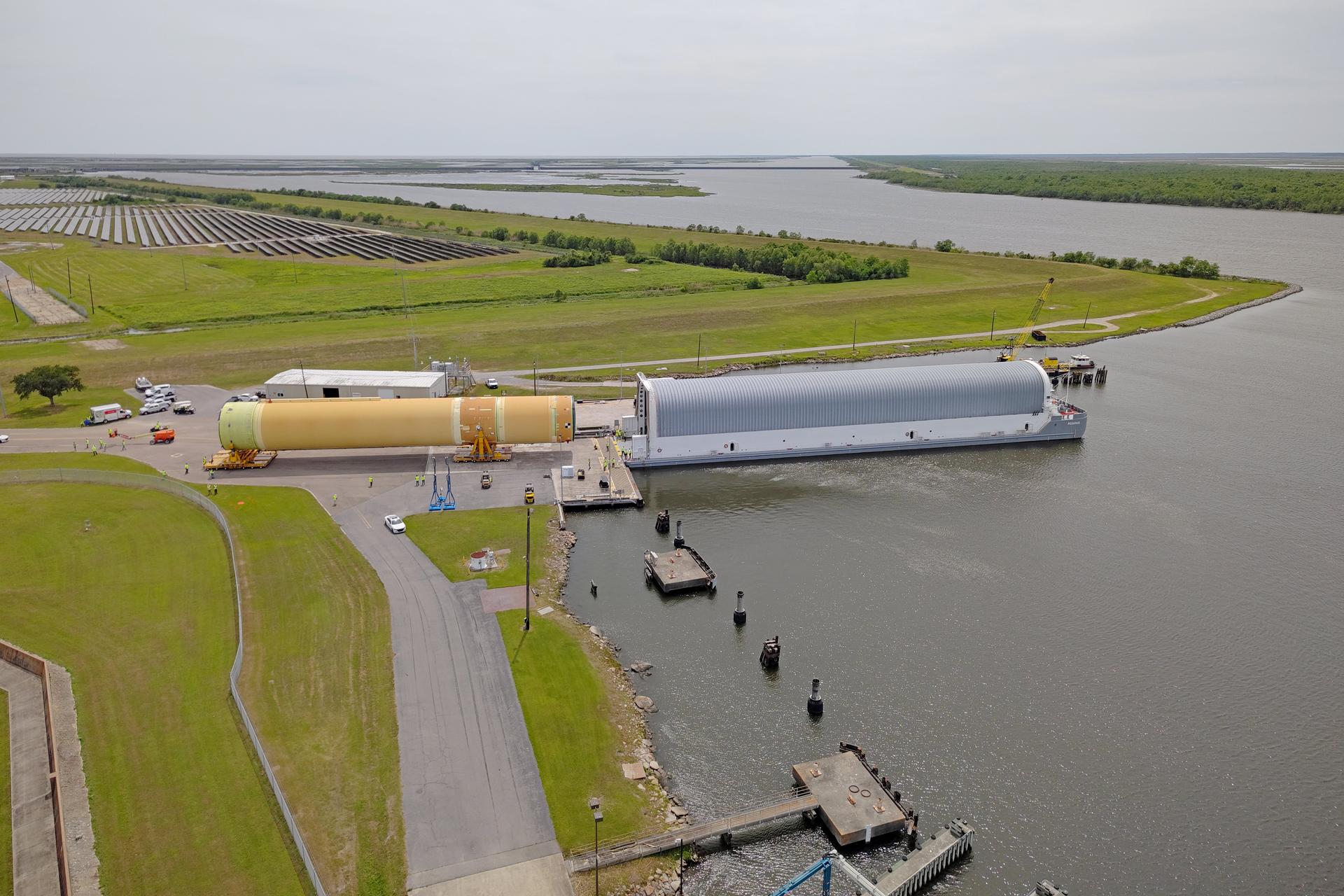
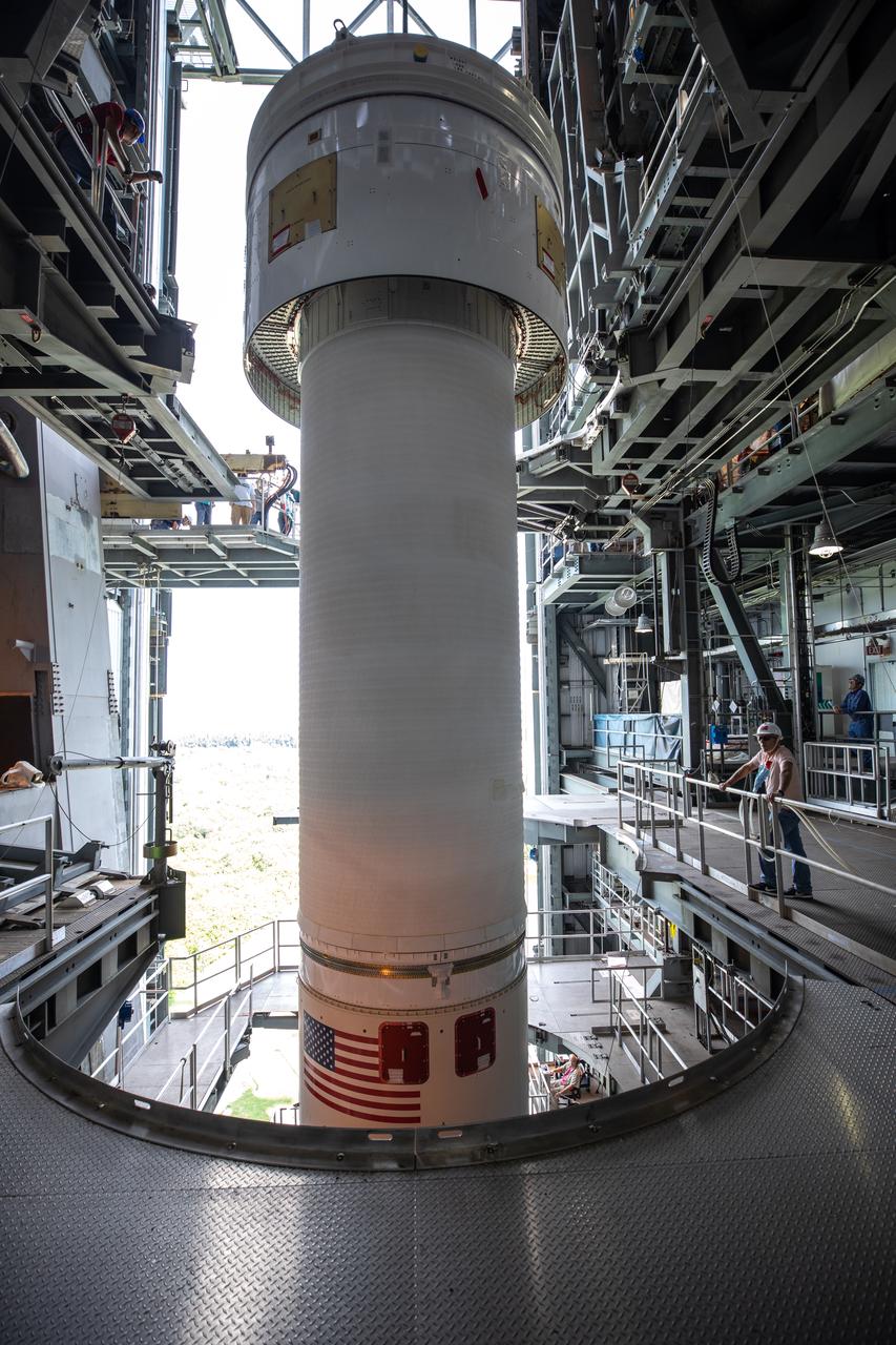
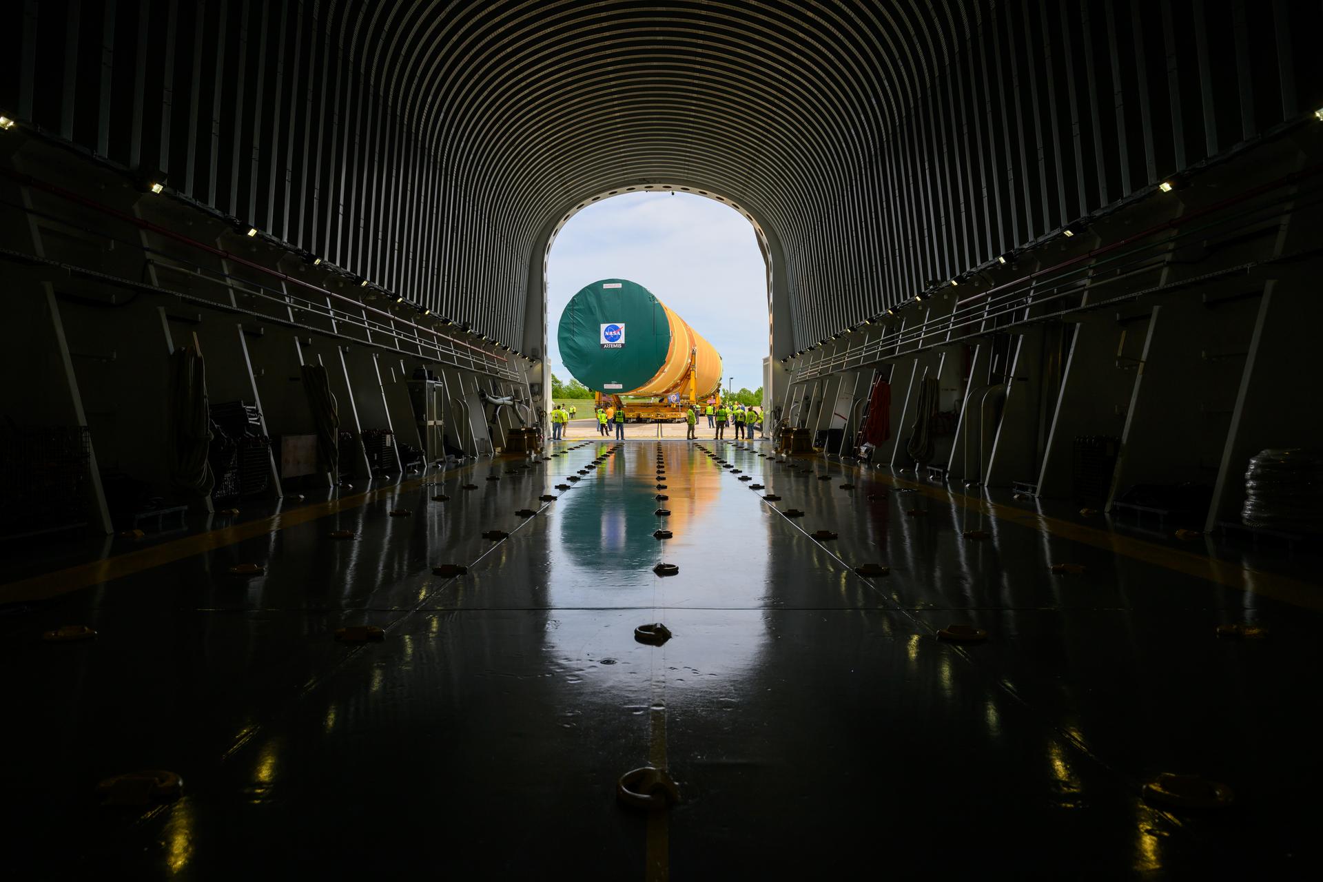
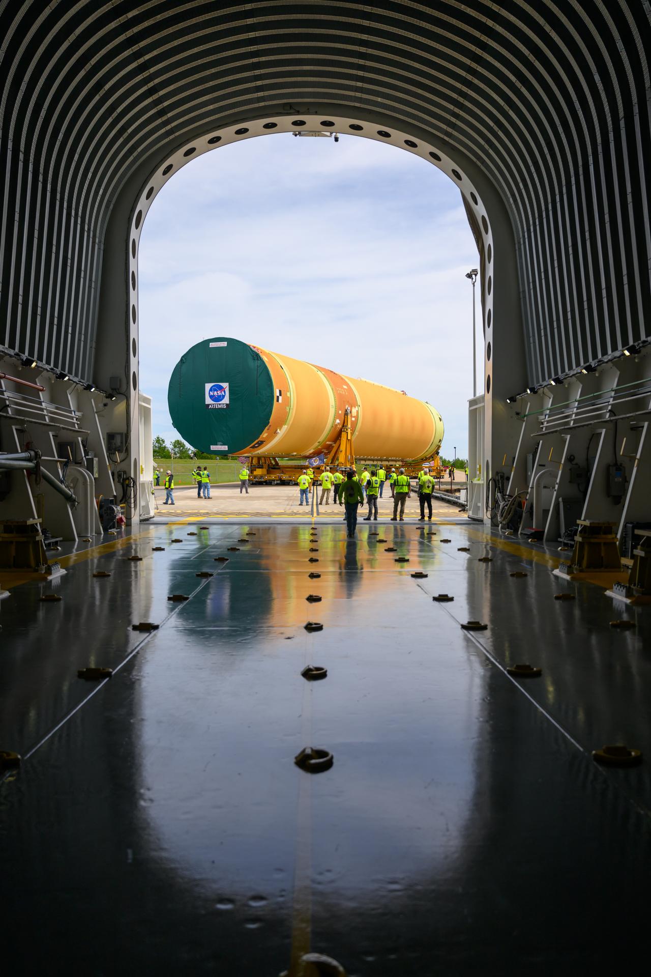
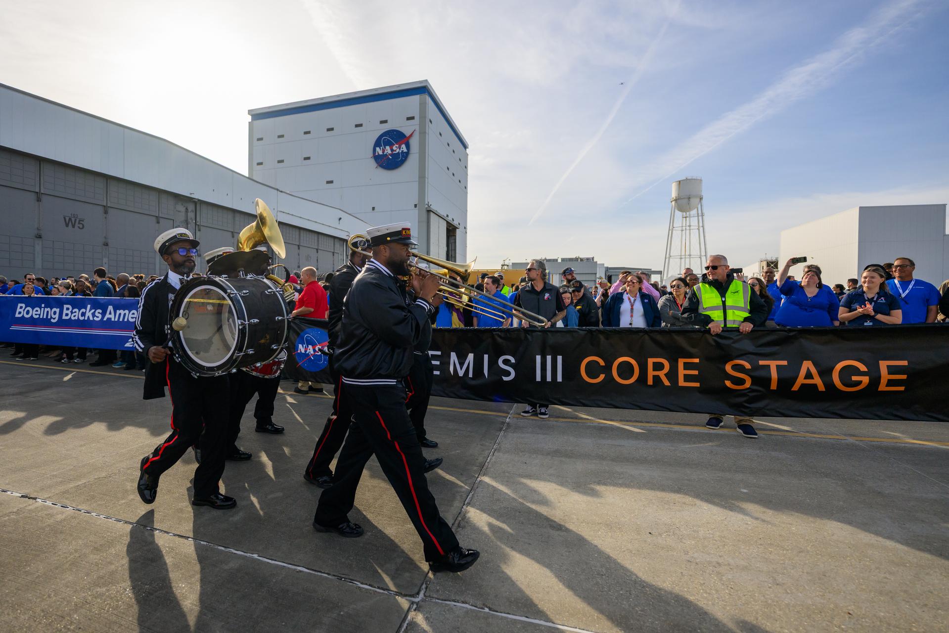
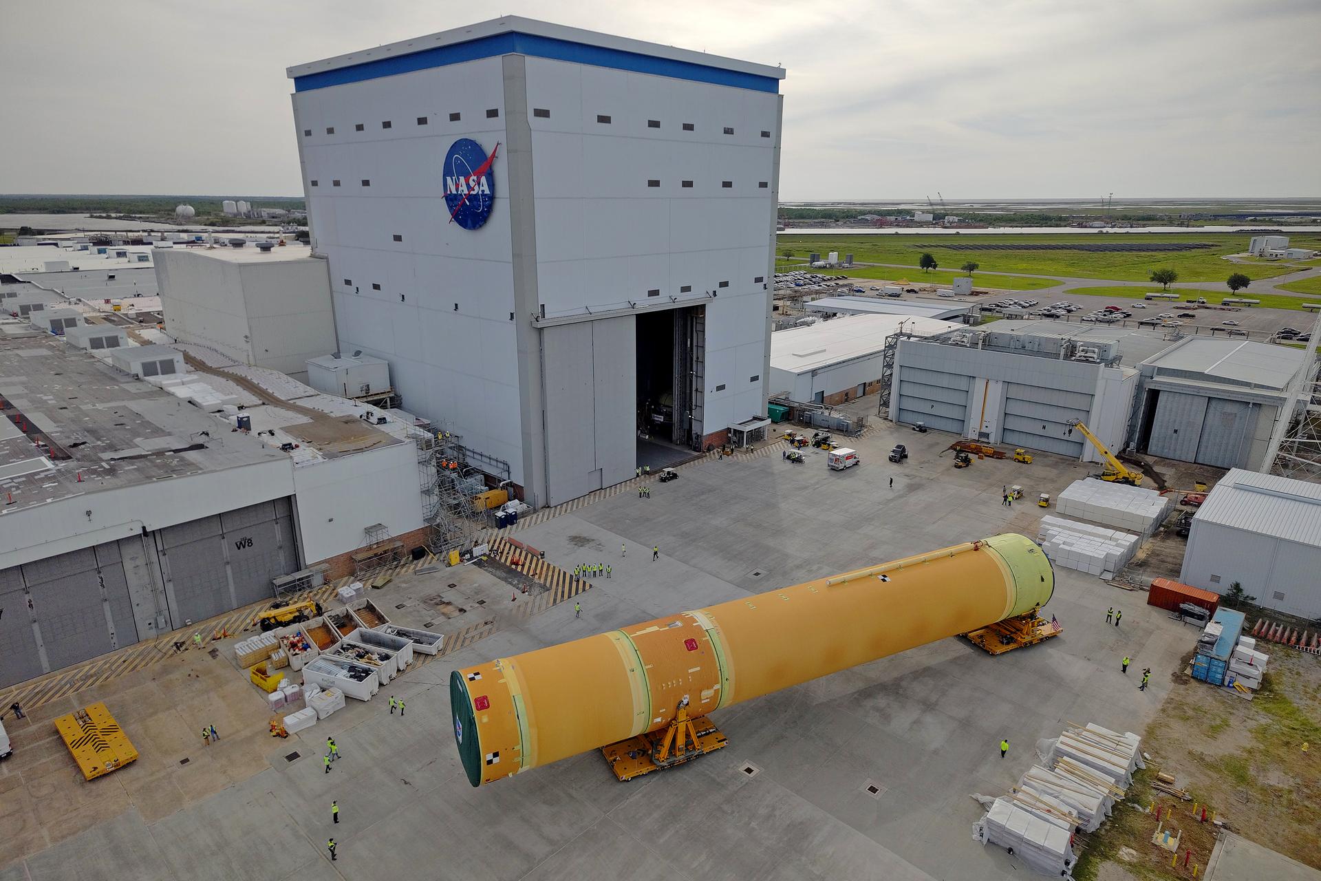
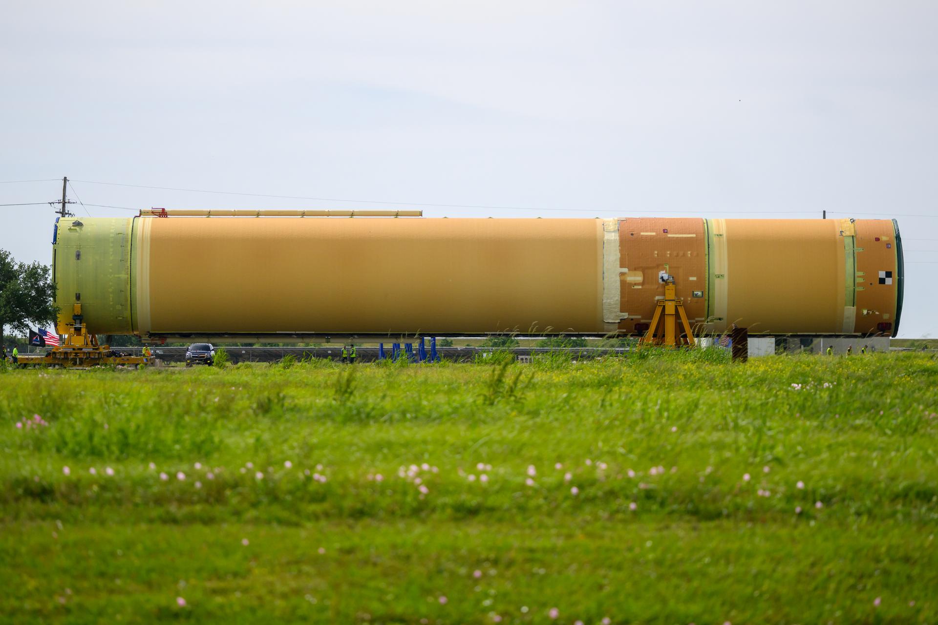
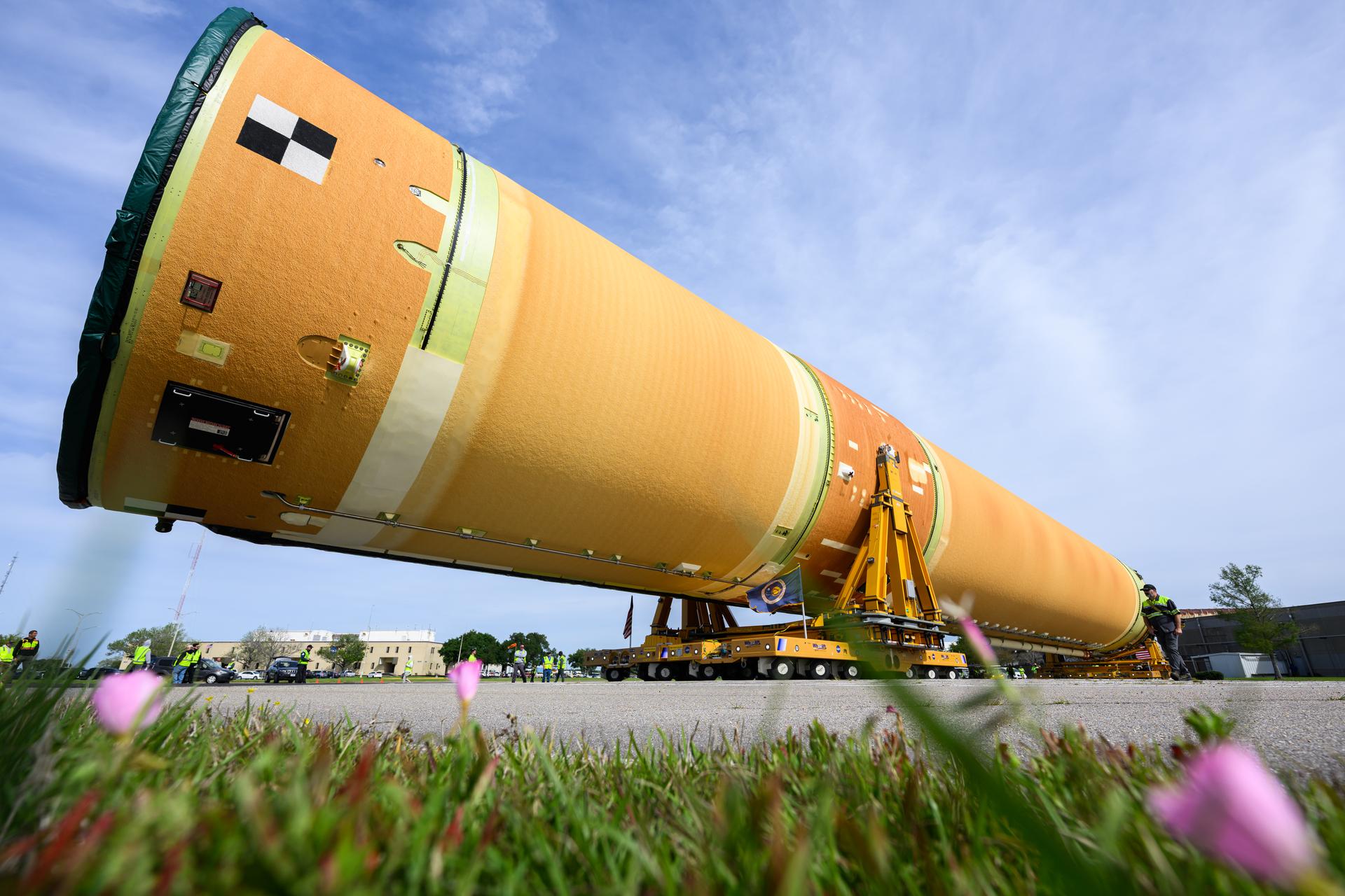
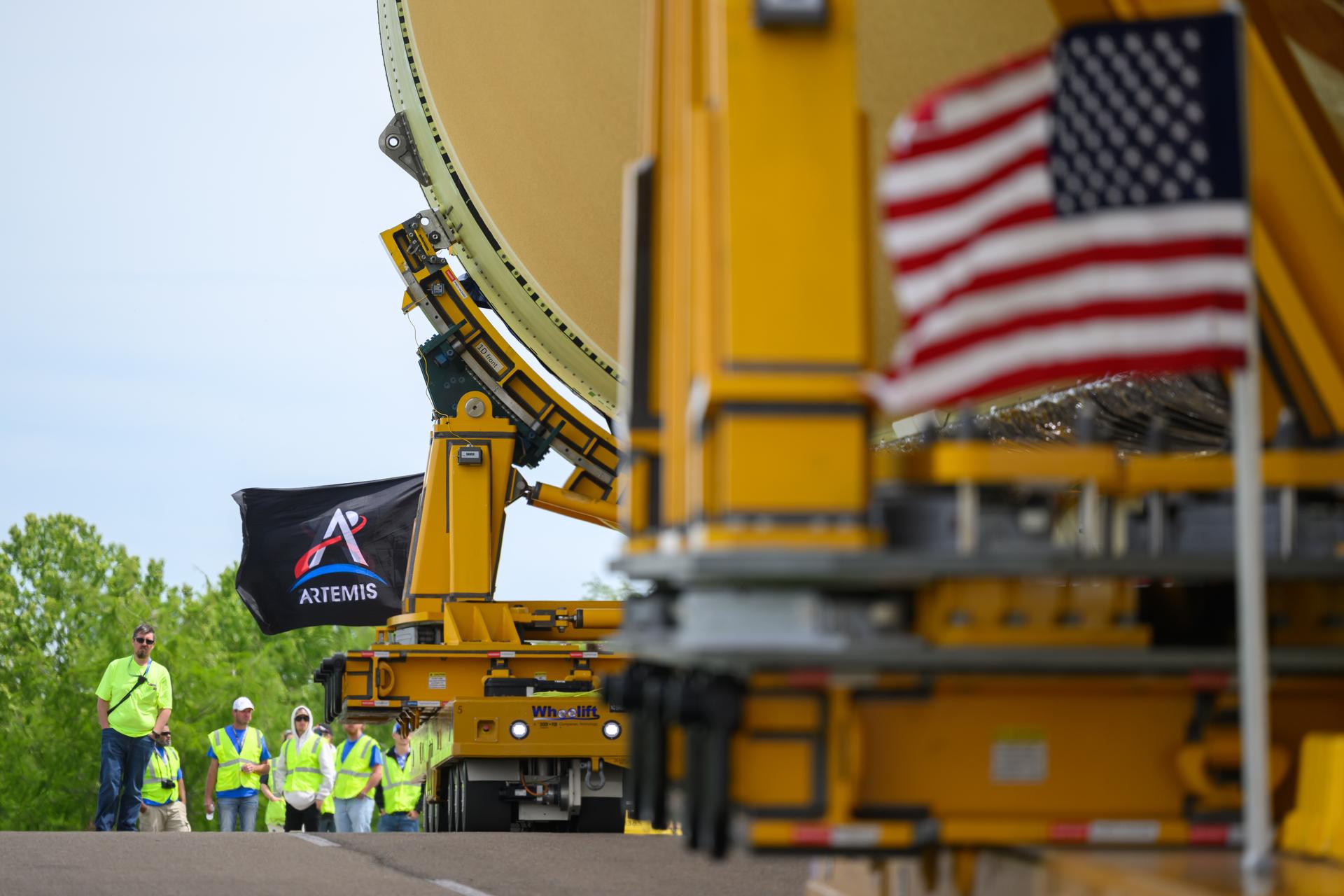
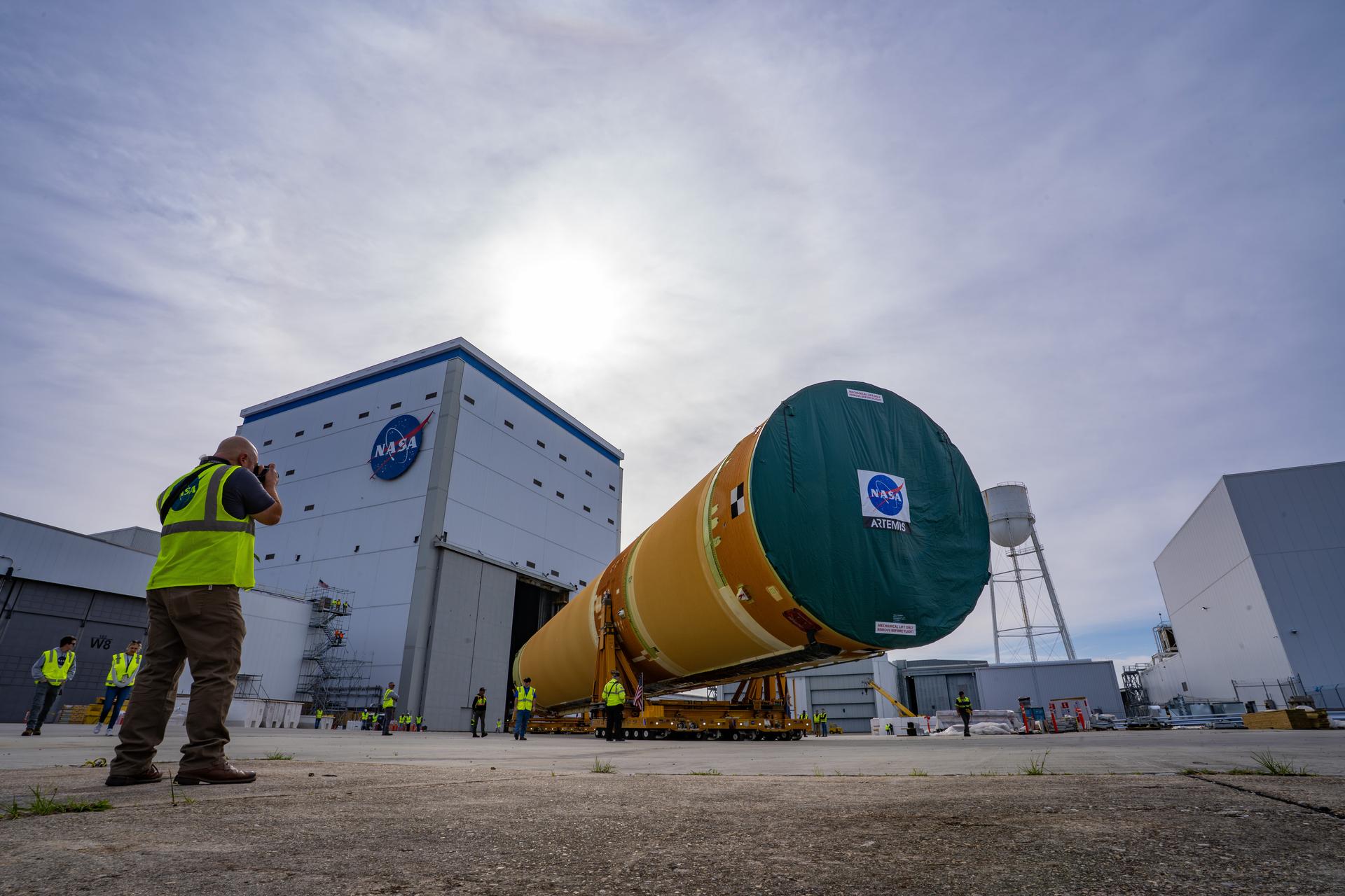
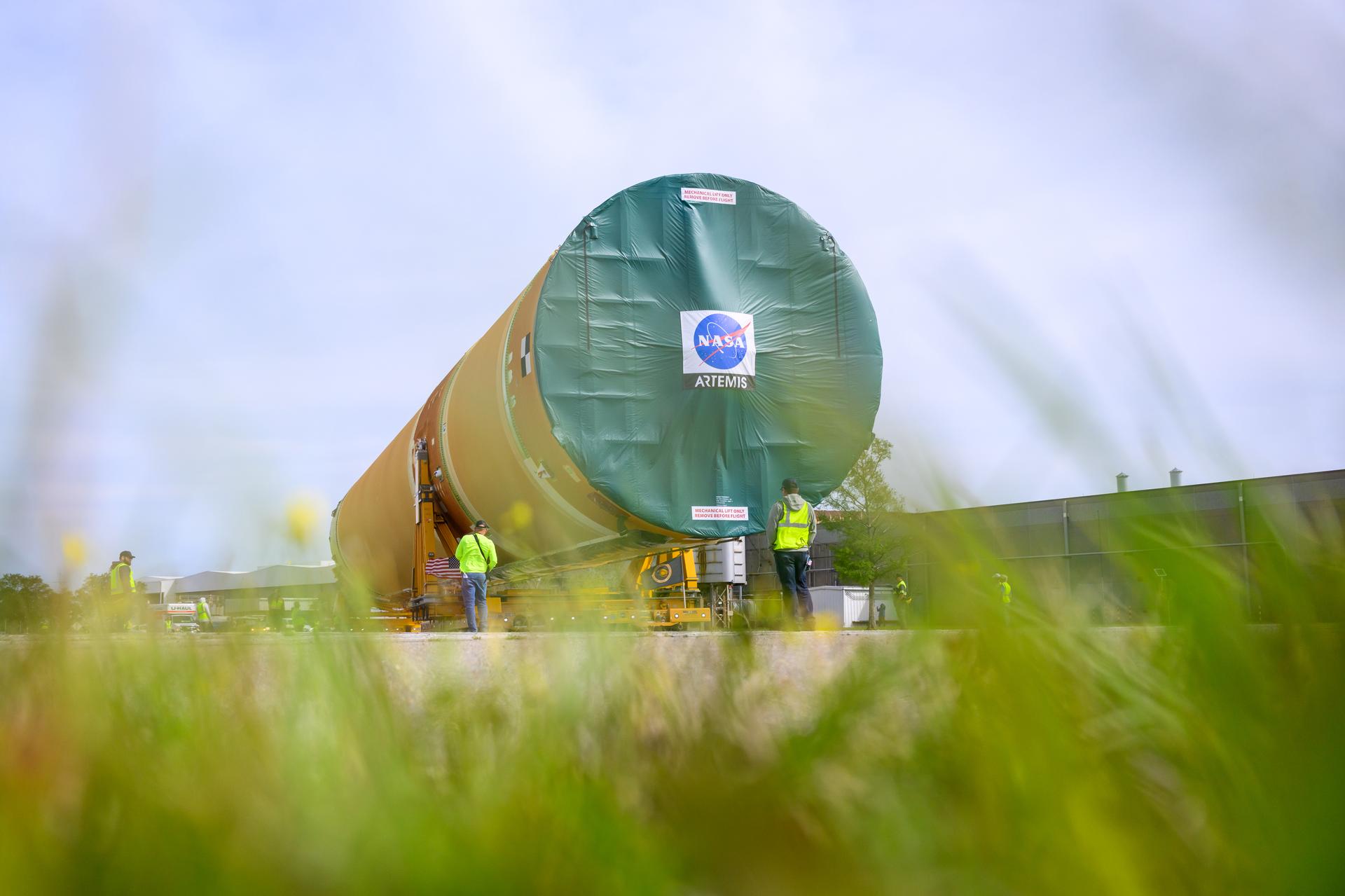
NASA moved the core stage, or the largest section, of the SLS (Space Launch System) rocket that will launch the crewed Artemis III mission in 2027 from the agency’s Michoud Assembly Facility to the agency’s Pegasus barge in New Orleans on April 20. The barge will ferry the top four-fifths – the section containing the liquid hydrogen tank, liquid oxygen tank, intertank, and forward skirt – of the SLS core stage to NASA’s Kennedy Space Center in Florida to complete outfitting and vertical integration. Teams with NASA and Boeing, the SLS core stage lead contractor, used specialized transporters to guide the top four-fifths from the NASA rocket factory to Pegasus. Prior to the move, technicians added an engine section transportation simulator to the rocket stage for shipment to the Space Coast. Next year’s Artemis III mission will launch astronauts to Earth’s orbit aboard the Orion spacecraft on top of SLS to test rendezvous and docking capabilities between Orion and commercial spacecraft needed to land Artemis IV astronauts on the Moon in 2028. NASA’s SLS is the only rocket capable of sending Orion, astronauts, and supplies to the Moon in a single launch.
NASA moved the core stage, or the largest section, of the SLS (Space Launch System) rocket that will launch the crewed Artemis III mission in 2027 from the agency’s Michoud Assembly Facility to the agency’s Pegasus barge in New Orleans on April 20. The barge will ferry the top four-fifths – the section containing the liquid hydrogen tank, liquid oxygen tank, intertank, and forward skirt – of the SLS core stage to NASA’s Kennedy Space Center in Florida to complete outfitting and vertical integration. Teams with NASA and Boeing, the SLS core stage lead contractor, used specialized transporters to guide the top four-fifths from the NASA rocket factory to Pegasus. Prior to the move, technicians added an engine section transportation simulator to the rocket stage for shipment to the Space Coast. Next year’s Artemis III mission will launch astronauts to Earth’s orbit aboard the Orion spacecraft on top of SLS to test rendezvous and docking capabilities between Orion and commercial spacecraft needed to land Artemis IV astronauts on the Moon in 2028. NASA’s SLS is the only rocket capable of sending Orion, astronauts, and supplies to the Moon in a single launch.
NASA moved the core stage, or the largest section, of the SLS (Space Launch System) rocket that will launch the crewed Artemis III mission in 2027 from the agency’s Michoud Assembly Facility to the agency’s Pegasus barge in New Orleans on April 20. The barge will ferry the top four-fifths – the section containing the liquid hydrogen tank, liquid oxygen tank, intertank, and forward skirt – of the SLS core stage to NASA’s Kennedy Space Center in Florida to complete outfitting and vertical integration. Teams with NASA and Boeing, the SLS core stage lead contractor, used specialized transporters to guide the top four-fifths from the NASA rocket factory to Pegasus. Prior to the move, technicians added an engine section transportation simulator to the rocket stage for shipment to the Space Coast. Next year’s Artemis III mission will launch astronauts to Earth’s orbit aboard the Orion spacecraft on top of SLS to test rendezvous and docking capabilities between Orion and commercial spacecraft needed to land Artemis IV astronauts on the Moon in 2028. NASA’s SLS is the only rocket capable of sending Orion, astronauts, and supplies to the Moon in a single launch.
NASA moved the core stage, or the largest section, of the SLS (Space Launch System) rocket that will launch the crewed Artemis III mission in 2027 from the agency’s Michoud Assembly Facility to the agency’s Pegasus barge in New Orleans on April 20. The barge will ferry the top four-fifths – the section containing the liquid hydrogen tank, liquid oxygen tank, intertank, and forward skirt – of the SLS core stage to NASA’s Kennedy Space Center in Florida to complete outfitting and vertical integration. Teams with NASA and Boeing, the SLS core stage lead contractor, used specialized transporters to guide the top four-fifths from the NASA rocket factory to Pegasus. Prior to the move, technicians added an engine section transportation simulator to the rocket stage for shipment to the Space Coast. Next year’s Artemis III mission will launch astronauts to Earth’s orbit aboard the Orion spacecraft on top of SLS to test rendezvous and docking capabilities between Orion and commercial spacecraft needed to land Artemis IV astronauts on the Moon in 2028. NASA’s SLS is the only rocket capable of sending Orion, astronauts, and supplies to the Moon in a single launch.
NASA moved the core stage, or the largest section, of the SLS (Space Launch System) rocket that will launch the crewed Artemis III mission in 2027 from the agency’s Michoud Assembly Facility to the agency’s Pegasus barge in New Orleans on April 20. The barge will ferry the top four-fifths – the section containing the liquid hydrogen tank, liquid oxygen tank, intertank, and forward skirt – of the SLS core stage to NASA’s Kennedy Space Center in Florida to complete outfitting and vertical integration. Teams with NASA and Boeing, the SLS core stage lead contractor, used specialized transporters to guide the top four-fifths from the NASA rocket factory to Pegasus. Prior to the move, technicians added an engine section transportation simulator to the rocket stage for shipment to the Space Coast. Next year’s Artemis III mission will launch astronauts to Earth’s orbit aboard the Orion spacecraft on top of SLS to test rendezvous and docking capabilities between Orion and commercial spacecraft needed to land Artemis IV astronauts on the Moon in 2028. NASA’s SLS is the only rocket capable of sending Orion, astronauts, and supplies to the Moon in a single launch.
NASA moved the core stage, or the largest section, of the SLS (Space Launch System) rocket that will launch the crewed Artemis III mission in 2027 from the agency’s Michoud Assembly Facility to the agency’s Pegasus barge in New Orleans on April 20. The barge will ferry the top four-fifths – the section containing the liquid hydrogen tank, liquid oxygen tank, intertank, and forward skirt – of the SLS core stage to NASA’s Kennedy Space Center in Florida to complete outfitting and vertical integration. Teams with NASA and Boeing, the SLS core stage lead contractor, used specialized transporters to guide the top four-fifths from the NASA rocket factory to Pegasus. Prior to the move, technicians added an engine section transportation simulator to the rocket stage for shipment to the Space Coast. Next year’s Artemis III mission will launch astronauts to Earth’s orbit aboard the Orion spacecraft on top of SLS to test rendezvous and docking capabilities between Orion and commercial spacecraft needed to land Artemis IV astronauts on the Moon in 2028. NASA’s SLS is the only rocket capable of sending Orion, astronauts, and supplies to the Moon in a single launch.
NASA moved the core stage, or the largest section, of the SLS (Space Launch System) rocket that will launch the crewed Artemis III mission in 2027 from the agency’s Michoud Assembly Facility to the agency’s Pegasus barge in New Orleans on April 20. The barge will ferry the top four-fifths – the section containing the liquid hydrogen tank, liquid oxygen tank, intertank, and forward skirt – of the SLS core stage to NASA’s Kennedy Space Center in Florida to complete outfitting and vertical integration. Teams with NASA and Boeing, the SLS core stage lead contractor, used specialized transporters to guide the top four-fifths from the NASA rocket factory to Pegasus. Prior to the move, technicians added an engine section transportation simulator to the rocket stage for shipment to the Space Coast. Next year’s Artemis III mission will launch astronauts to Earth’s orbit aboard the Orion spacecraft on top of SLS to test rendezvous and docking capabilities between Orion and commercial spacecraft needed to land Artemis IV astronauts on the Moon in 2028. NASA’s SLS is the only rocket capable of sending Orion, astronauts, and supplies to the Moon in a single launch. Photo Credit: NASA/Eric Bordelon
NASA moved the core stage, or the largest section, of the SLS (Space Launch System) rocket that will launch the crewed Artemis III mission in 2027 from the agency’s Michoud Assembly Facility to the agency’s Pegasus barge in New Orleans on April 20. The barge will ferry the top four-fifths – the section containing the liquid hydrogen tank, liquid oxygen tank, intertank, and forward skirt – of the SLS core stage to NASA’s Kennedy Space Center in Florida to complete outfitting and vertical integration. Teams with NASA and Boeing, the SLS core stage lead contractor, used specialized transporters to guide the top four-fifths from the NASA rocket factory to Pegasus. Prior to the move, technicians added an engine section transportation simulator to the rocket stage for shipment to the Space Coast. Next year’s Artemis III mission will launch astronauts to Earth’s orbit aboard the Orion spacecraft on top of SLS to test rendezvous and docking capabilities between Orion and commercial spacecraft needed to land Artemis IV astronauts on the Moon in 2028. NASA’s SLS is the only rocket capable of sending Orion, astronauts, and supplies to the Moon in a single launch. Photo Credit: NASA/Eric Bordelon
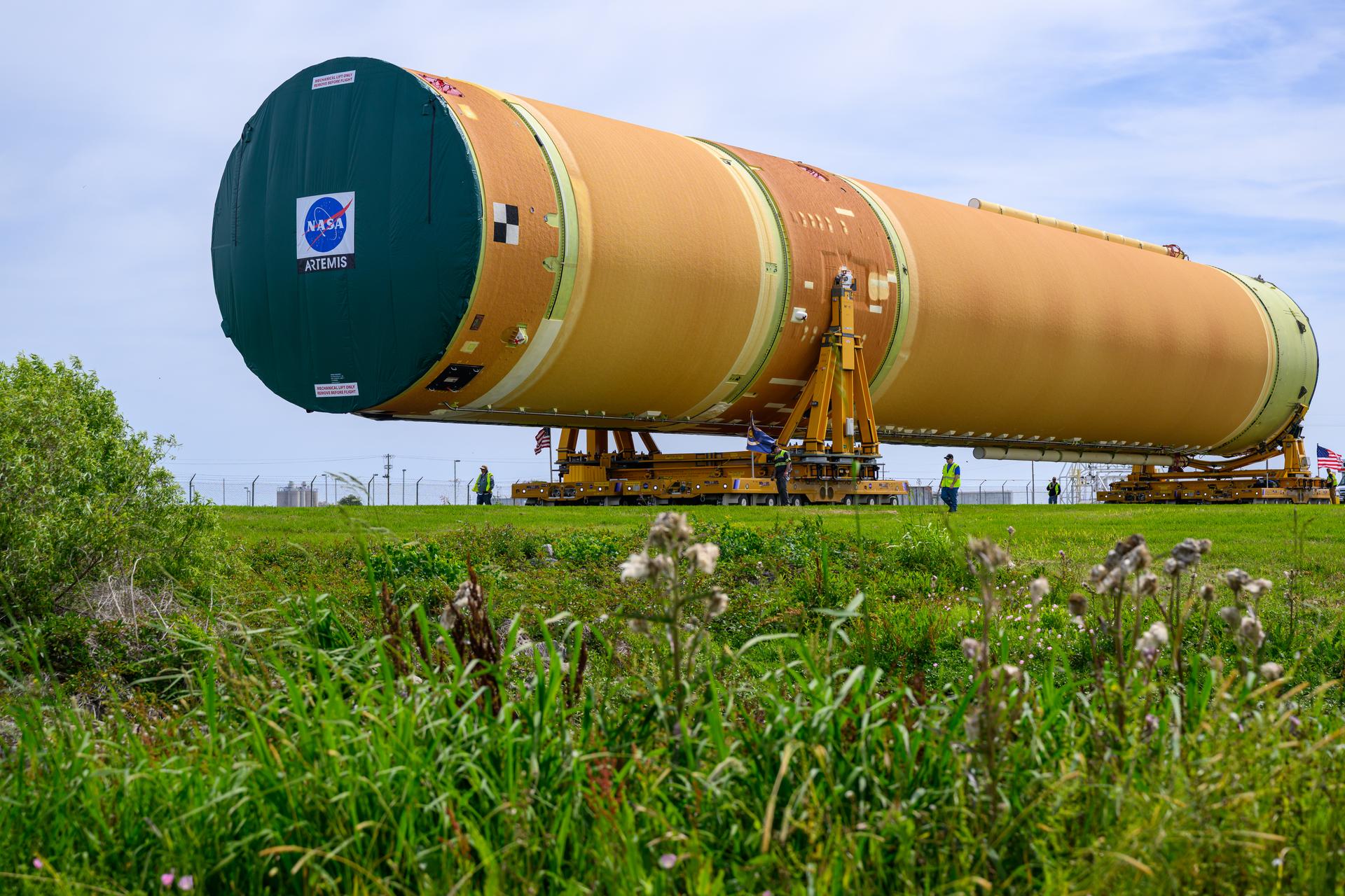
NASA moved the core stage, or the largest section, of the SLS (Space Launch System) rocket that will launch the crewed Artemis III mission in 2027 from the agency’s Michoud Assembly Facility to the agency’s Pegasus barge in New Orleans on April 20. The barge will ferry the top four-fifths – the section containing the liquid hydrogen tank, liquid oxygen tank, intertank, and forward skirt – of the SLS core stage to NASA’s Kennedy Space Center in Florida to complete outfitting and vertical integration. Teams with NASA and Boeing, the SLS core stage lead contractor, used specialized transporters to guide the top four-fifths from the NASA rocket factory to Pegasus. Prior to the move, technicians added an engine section transportation simulator to the rocket stage for shipment to the Space Coast. Next year’s Artemis III mission will launch astronauts to Earth’s orbit aboard the Orion spacecraft on top of SLS to test rendezvous and docking capabilities between Orion and commercial spacecraft needed to land Artemis IV astronauts on the Moon in 2028. NASA’s SLS is the only rocket capable of sending Orion, astronauts, and supplies to the Moon in a single launch. Photo Credit: NASA/Eric Bordelon
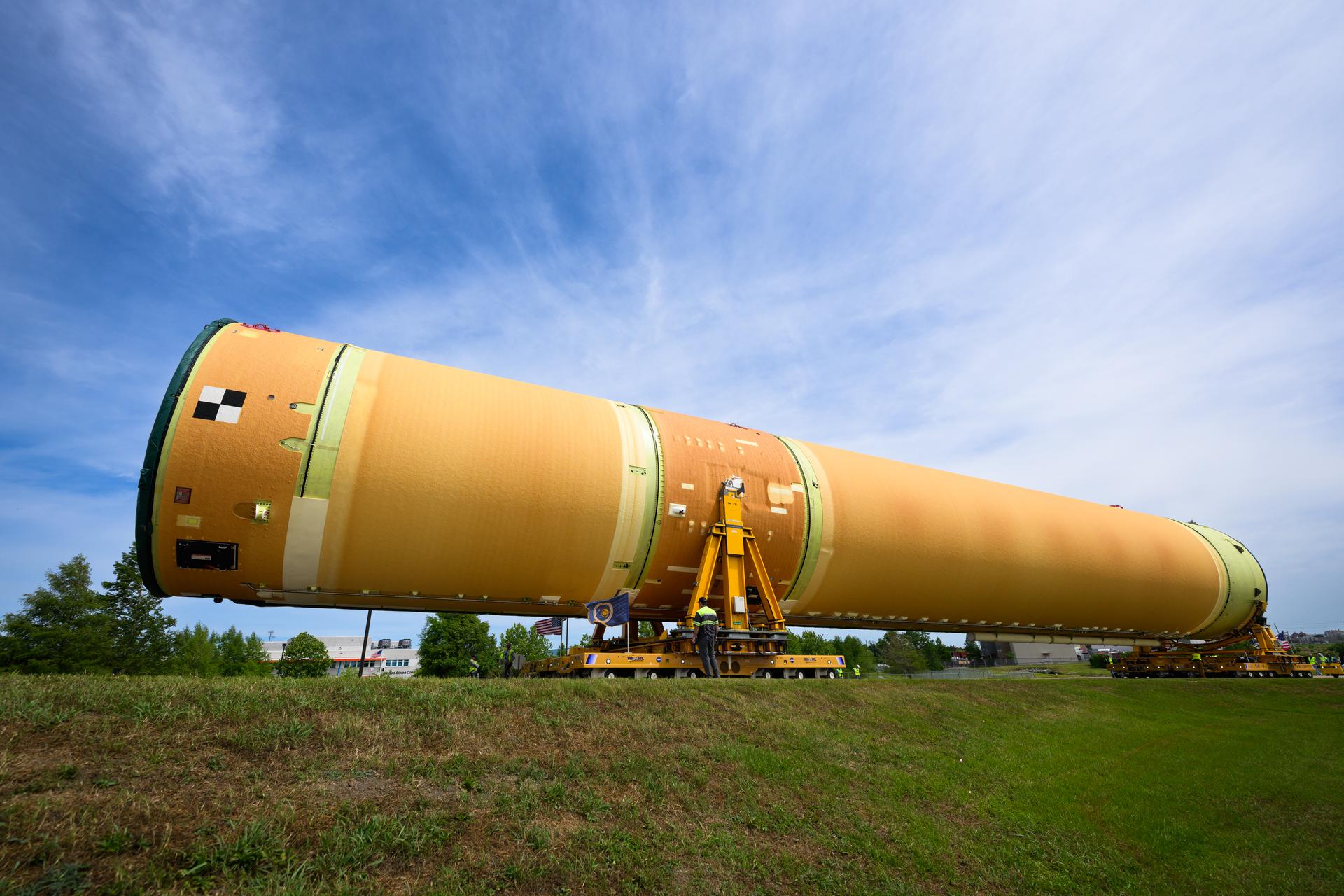
NASA moved the core stage, or the largest section, of the SLS (Space Launch System) rocket that will launch the crewed Artemis III mission in 2027 from the agency’s Michoud Assembly Facility to the agency’s Pegasus barge in New Orleans on April 20. The barge will ferry the top four-fifths – the section containing the liquid hydrogen tank, liquid oxygen tank, intertank, and forward skirt – of the SLS core stage to NASA’s Kennedy Space Center in Florida to complete outfitting and vertical integration. Teams with NASA and Boeing, the SLS core stage lead contractor, used specialized transporters to guide the top four-fifths from the NASA rocket factory to Pegasus. Prior to the move, technicians added an engine section transportation simulator to the rocket stage for shipment to the Space Coast. Next year’s Artemis III mission will launch astronauts to Earth’s orbit aboard the Orion spacecraft on top of SLS to test rendezvous and docking capabilities between Orion and commercial spacecraft needed to land Artemis IV astronauts on the Moon in 2028. NASA’s SLS is the only rocket capable of sending Orion, astronauts, and supplies to the Moon in a single launch. Photo Credit: NASA/Eric Bordelon
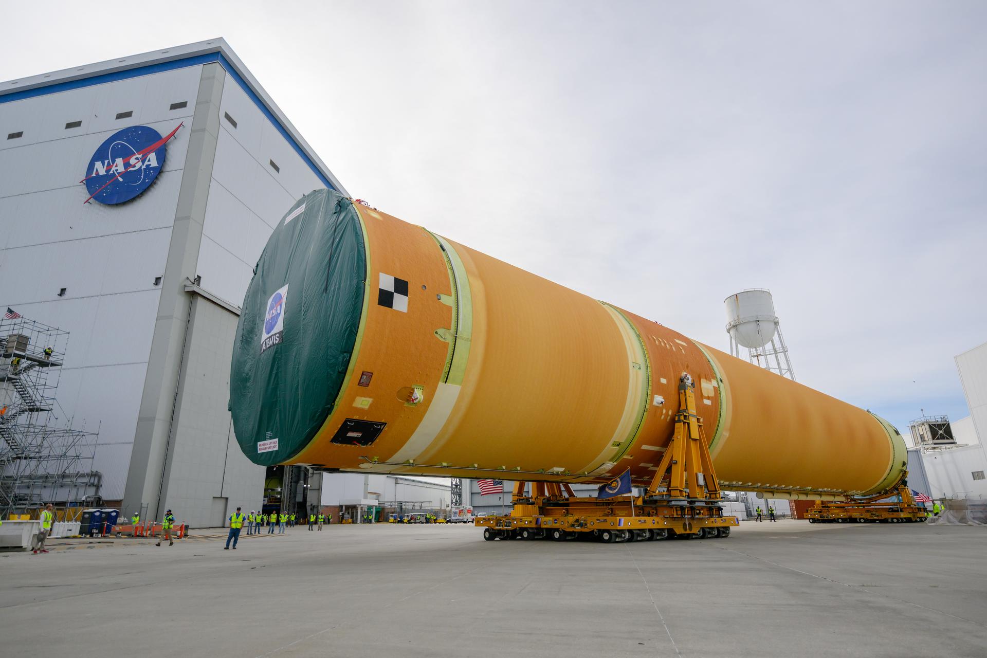
NASA moved the core stage, or the largest section, of the SLS (Space Launch System) rocket that will launch the crewed Artemis III mission in 2027 from the agency’s Michoud Assembly Facility to the agency’s Pegasus barge in New Orleans on April 20. The barge will ferry the top four-fifths – the section containing the liquid hydrogen tank, liquid oxygen tank, intertank, and forward skirt – of the SLS core stage to NASA’s Kennedy Space Center in Florida to complete outfitting and vertical integration. Teams with NASA and Boeing, the SLS core stage lead contractor, used specialized transporters to guide the top four-fifths from the NASA rocket factory to Pegasus. Prior to the move, technicians added an engine section transportation simulator to the rocket stage for shipment to the Space Coast. Next year’s Artemis III mission will launch astronauts to Earth’s orbit aboard the Orion spacecraft on top of SLS to test rendezvous and docking capabilities between Orion and commercial spacecraft needed to land Artemis IV astronauts on the Moon in 2028. NASA’s SLS is the only rocket capable of sending Orion, astronauts, and supplies to the Moon in a single launch. Photo Credit: NASA/Eric Bordelon
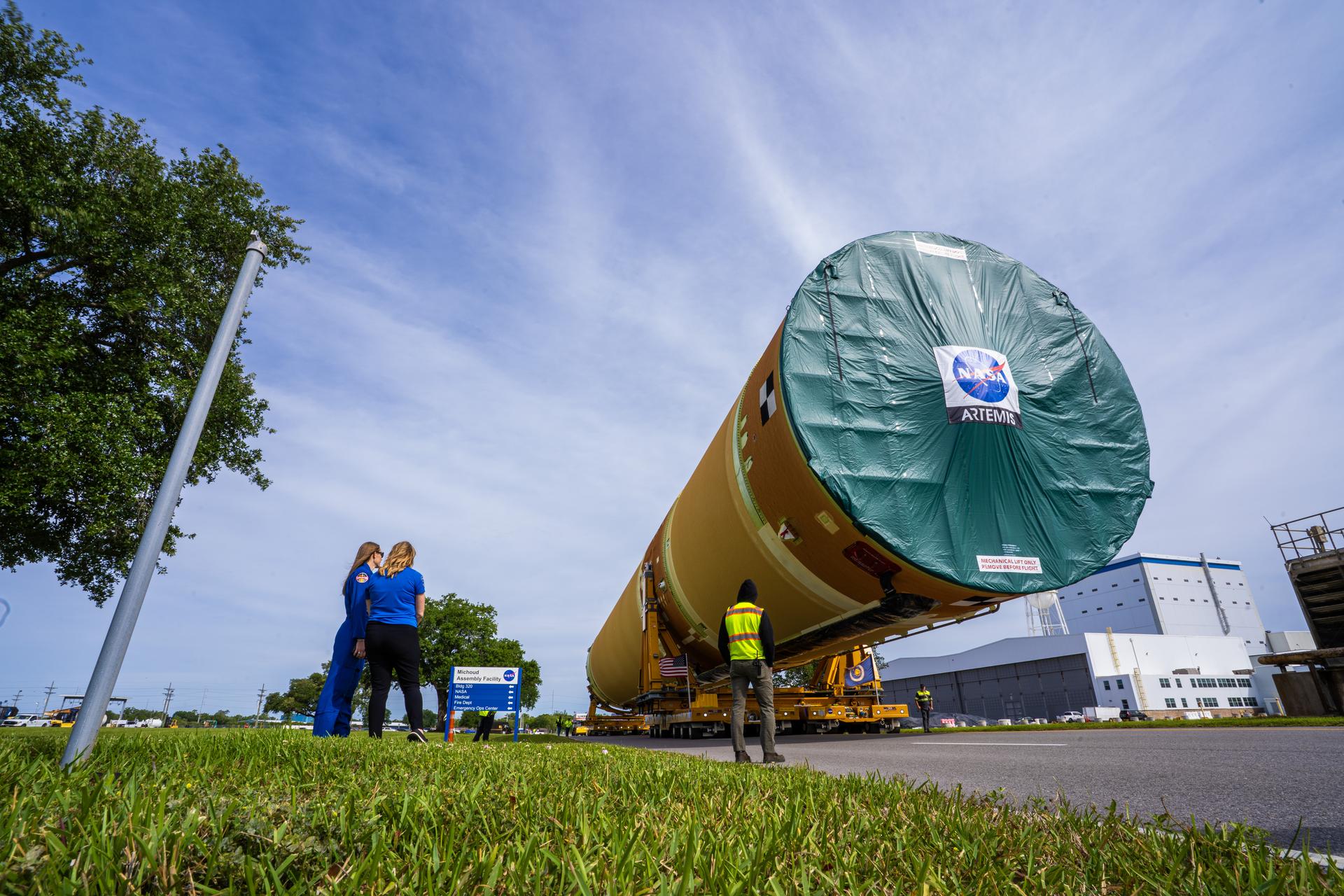
NASA moved the core stage, or the largest section, of the SLS (Space Launch System) rocket that will launch the crewed Artemis III mission in 2027 from the agency’s Michoud Assembly Facility to the agency’s Pegasus barge in New Orleans on April 20. The barge will ferry the top four-fifths – the section containing the liquid hydrogen tank, liquid oxygen tank, intertank, and forward skirt – of the SLS core stage to NASA’s Kennedy Space Center in Florida to complete outfitting and vertical integration. Teams with NASA and Boeing, the SLS core stage lead contractor, used specialized transporters to guide the top four-fifths from the NASA rocket factory to Pegasus. Prior to the move, technicians added an engine section transportation simulator to the rocket stage for shipment to the Space Coast. Next year’s Artemis III mission will launch astronauts to Earth’s orbit aboard the Orion spacecraft on top of SLS to test rendezvous and docking capabilities between Orion and commercial spacecraft needed to land Artemis IV astronauts on the Moon in 2028. NASA’s SLS is the only rocket capable of sending Orion, astronauts, and supplies to the Moon in a single launch.
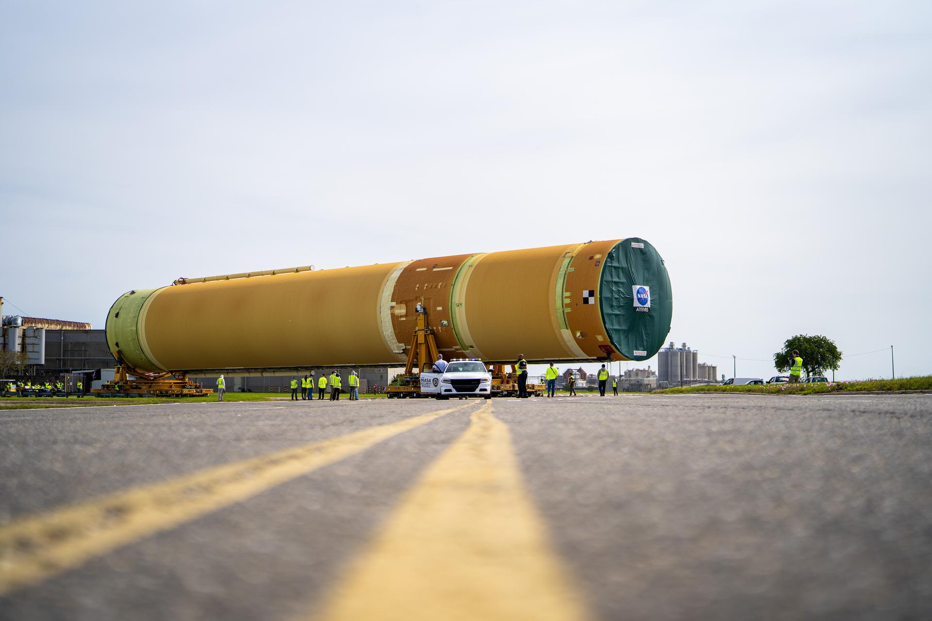
NASA moved the core stage, or the largest section, of the SLS (Space Launch System) rocket that will launch the crewed Artemis III mission in 2027 from the agency’s Michoud Assembly Facility to the agency’s Pegasus barge in New Orleans on April 20. The barge will ferry the top four-fifths – the section containing the liquid hydrogen tank, liquid oxygen tank, intertank, and forward skirt – of the SLS core stage to NASA’s Kennedy Space Center in Florida to complete outfitting and vertical integration. Teams with NASA and Boeing, the SLS core stage lead contractor, used specialized transporters to guide the top four-fifths from the NASA rocket factory to Pegasus. Prior to the move, technicians added an engine section transportation simulator to the rocket stage for shipment to the Space Coast. Next year’s Artemis III mission will launch astronauts to Earth’s orbit aboard the Orion spacecraft on top of SLS to test rendezvous and docking capabilities between Orion and commercial spacecraft needed to land Artemis IV astronauts on the Moon in 2028. NASA’s SLS is the only rocket capable of sending Orion, astronauts, and supplies to the Moon in a single launch.
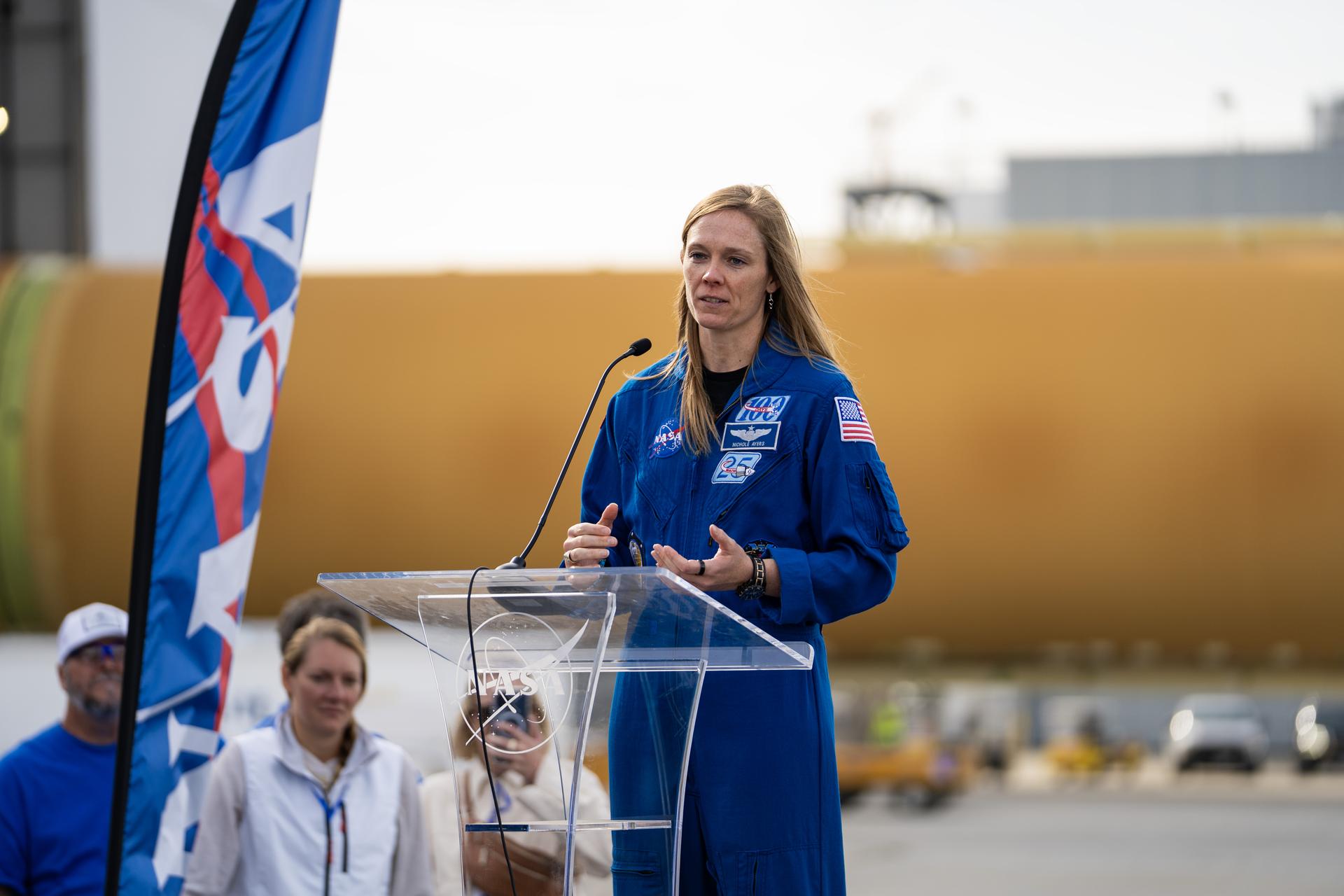
NASA moved the core stage, or the largest section, of the SLS (Space Launch System) rocket that will launch the crewed Artemis III mission in 2027 from the agency’s Michoud Assembly Facility to the agency’s Pegasus barge in New Orleans on April 20. The barge will ferry the top four-fifths – the section containing the liquid hydrogen tank, liquid oxygen tank, intertank, and forward skirt – of the SLS core stage to NASA’s Kennedy Space Center in Florida to complete outfitting and vertical integration. Teams with NASA and Boeing, the SLS core stage lead contractor, used specialized transporters to guide the top four-fifths from the NASA rocket factory to Pegasus. Prior to the move, technicians added an engine section transportation simulator to the rocket stage for shipment to the Space Coast. Next year’s Artemis III mission will launch astronauts to Earth’s orbit aboard the Orion spacecraft on top of SLS to test rendezvous and docking capabilities between Orion and commercial spacecraft needed to land Artemis IV astronauts on the Moon in 2028. NASA’s SLS is the only rocket capable of sending Orion, astronauts, and supplies to the Moon in a single launch.
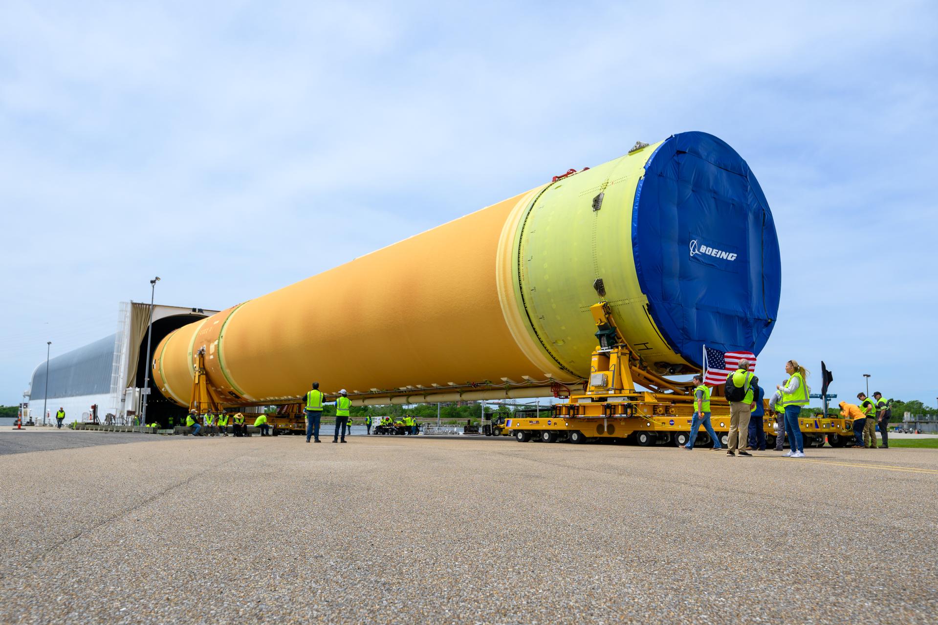
NASA moved the core stage, or the largest section, of the SLS (Space Launch System) rocket that will launch the crewed Artemis III mission in 2027 from the agency’s Michoud Assembly Facility to the agency’s Pegasus barge in New Orleans on April 20. The barge will ferry the top four-fifths – the section containing the liquid hydrogen tank, liquid oxygen tank, intertank, and forward skirt – of the SLS core stage to NASA’s Kennedy Space Center in Florida to complete outfitting and vertical integration. Teams with NASA and Boeing, the SLS core stage lead contractor, used specialized transporters to guide the top four-fifths from the NASA rocket factory to Pegasus. Prior to the move, technicians added an engine section transportation simulator to the rocket stage for shipment to the Space Coast. Next year’s Artemis III mission will launch astronauts to Earth’s orbit aboard the Orion spacecraft on top of SLS to test rendezvous and docking capabilities between Orion and commercial spacecraft needed to land Artemis IV astronauts on the Moon in 2028. NASA’s SLS is the only rocket capable of sending Orion, astronauts, and supplies to the Moon in a single launch. Photo Credit: NASA/Eric Bordelon
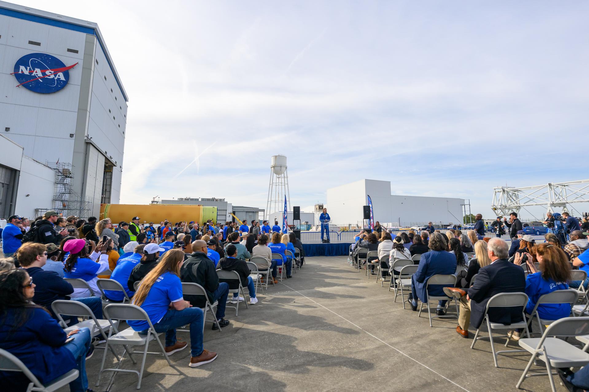
NASA moved the core stage, or the largest section, of the SLS (Space Launch System) rocket that will launch the crewed Artemis III mission in 2027 from the agency’s Michoud Assembly Facility to the agency’s Pegasus barge in New Orleans on April 20. The barge will ferry the top four-fifths – the section containing the liquid hydrogen tank, liquid oxygen tank, intertank, and forward skirt – of the SLS core stage to NASA’s Kennedy Space Center in Florida to complete outfitting and vertical integration. Teams with NASA and Boeing, the SLS core stage lead contractor, used specialized transporters to guide the top four-fifths from the NASA rocket factory to Pegasus. Prior to the move, technicians added an engine section transportation simulator to the rocket stage for shipment to the Space Coast. Next year’s Artemis III mission will launch astronauts to Earth’s orbit aboard the Orion spacecraft on top of SLS to test rendezvous and docking capabilities between Orion and commercial spacecraft needed to land Artemis IV astronauts on the Moon in 2028. NASA’s SLS is the only rocket capable of sending Orion, astronauts, and supplies to the Moon in a single launch. Photo Credit: NASA/Eric Bordelon
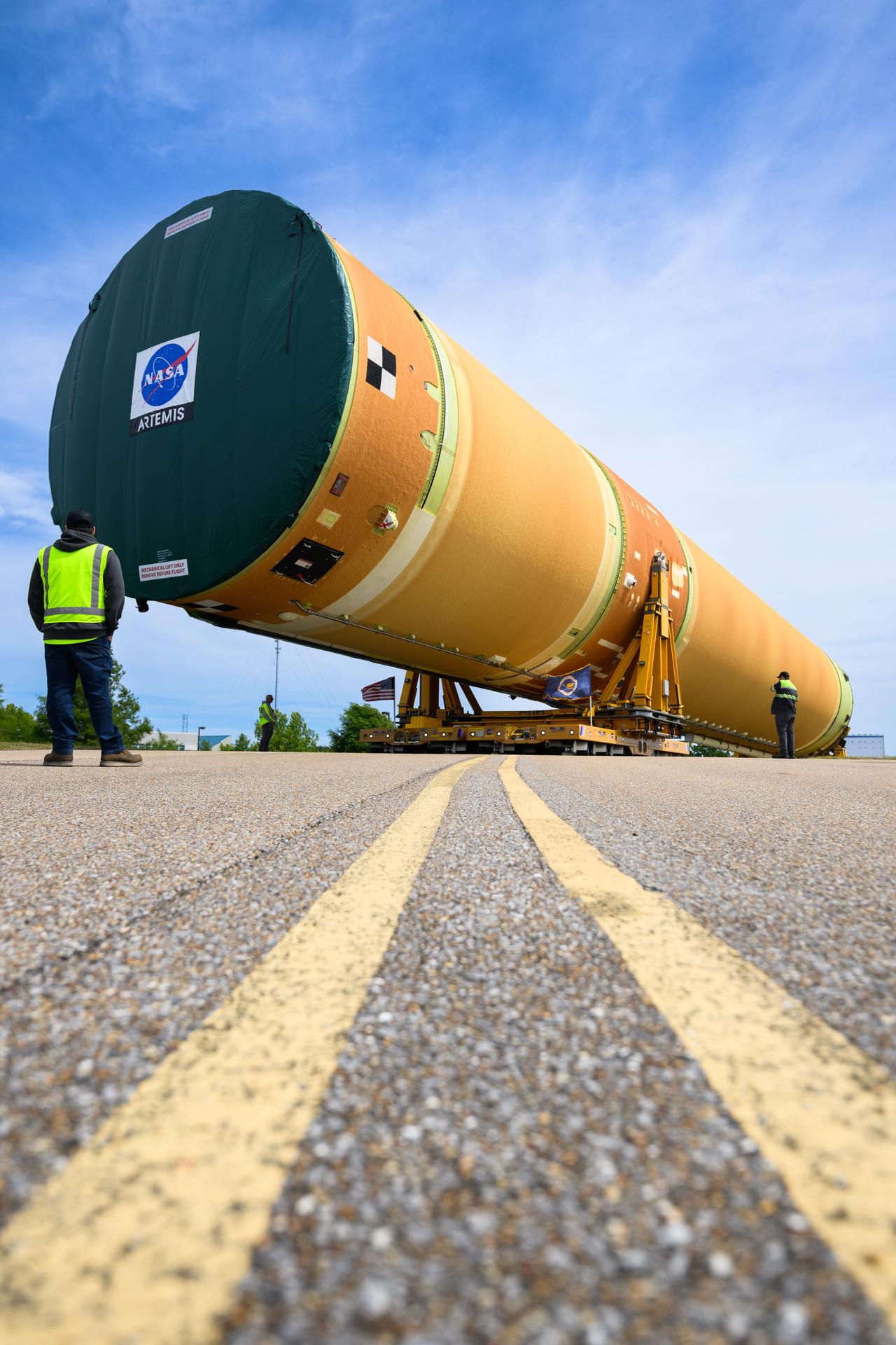
NASA moved the core stage, or the largest section, of the SLS (Space Launch System) rocket that will launch the crewed Artemis III mission in 2027 from the agency’s Michoud Assembly Facility to the agency’s Pegasus barge in New Orleans on April 20. The barge will ferry the top four-fifths – the section containing the liquid hydrogen tank, liquid oxygen tank, intertank, and forward skirt – of the SLS core stage to NASA’s Kennedy Space Center in Florida to complete outfitting and vertical integration. Teams with NASA and Boeing, the SLS core stage lead contractor, used specialized transporters to guide the top four-fifths from the NASA rocket factory to Pegasus. Prior to the move, technicians added an engine section transportation simulator to the rocket stage for shipment to the Space Coast. Next year’s Artemis III mission will launch astronauts to Earth’s orbit aboard the Orion spacecraft on top of SLS to test rendezvous and docking capabilities between Orion and commercial spacecraft needed to land Artemis IV astronauts on the Moon in 2028. NASA’s SLS is the only rocket capable of sending Orion, astronauts, and supplies to the Moon in a single launch. Photo Credit: NASA/Eric Bordelon
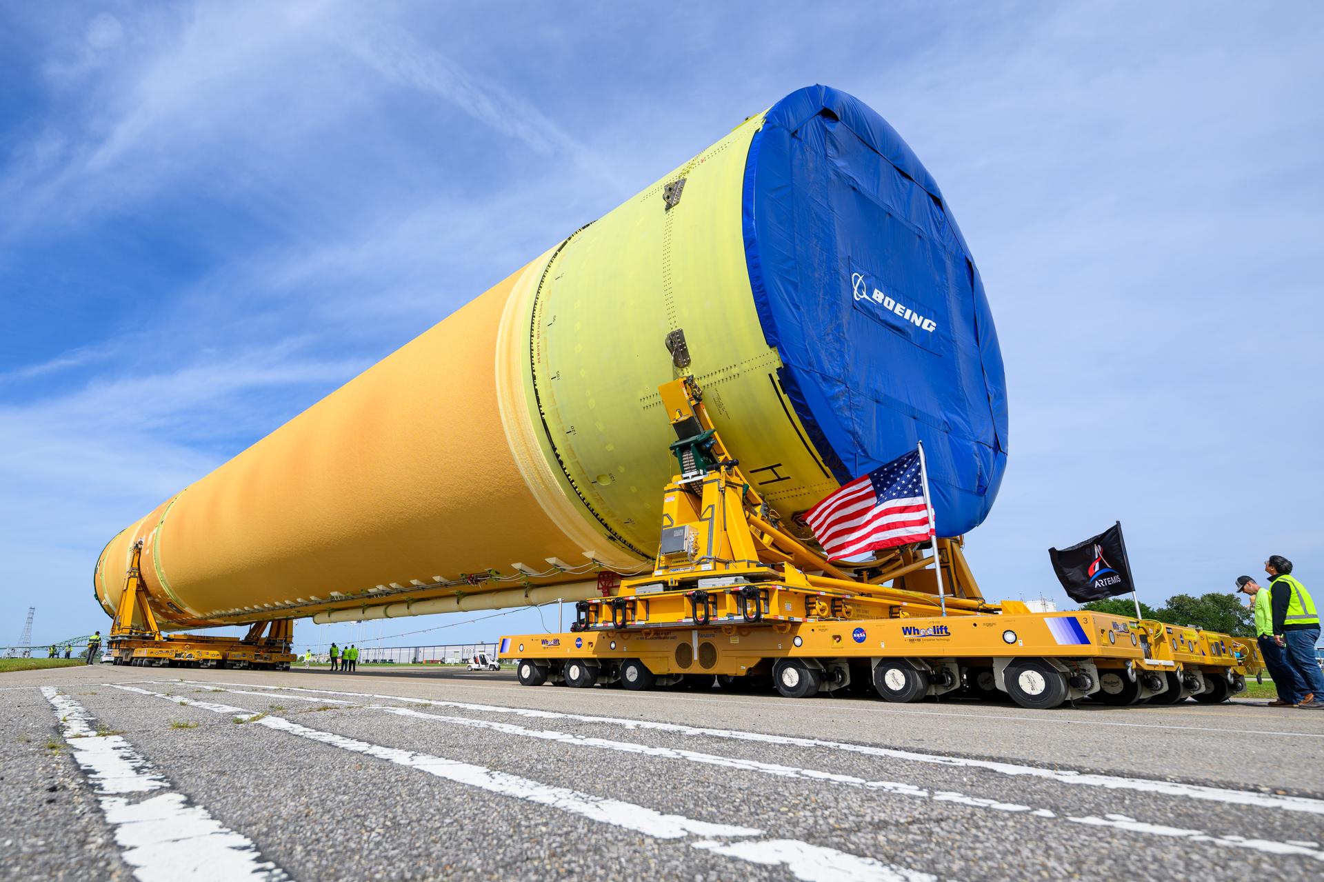
NASA moved the core stage, or the largest section, of the SLS (Space Launch System) rocket that will launch the crewed Artemis III mission in 2027 from the agency’s Michoud Assembly Facility to the agency’s Pegasus barge in New Orleans on April 20. The barge will ferry the top four-fifths – the section containing the liquid hydrogen tank, liquid oxygen tank, intertank, and forward skirt – of the SLS core stage to NASA’s Kennedy Space Center in Florida to complete outfitting and vertical integration. Teams with NASA and Boeing, the SLS core stage lead contractor, used specialized transporters to guide the top four-fifths from the NASA rocket factory to Pegasus. Prior to the move, technicians added an engine section transportation simulator to the rocket stage for shipment to the Space Coast. Next year’s Artemis III mission will launch astronauts to Earth’s orbit aboard the Orion spacecraft on top of SLS to test rendezvous and docking capabilities between Orion and commercial spacecraft needed to land Artemis IV astronauts on the Moon in 2028. NASA’s SLS is the only rocket capable of sending Orion, astronauts, and supplies to the Moon in a single launch. Photo Credit: NASA/Eric Bordelon
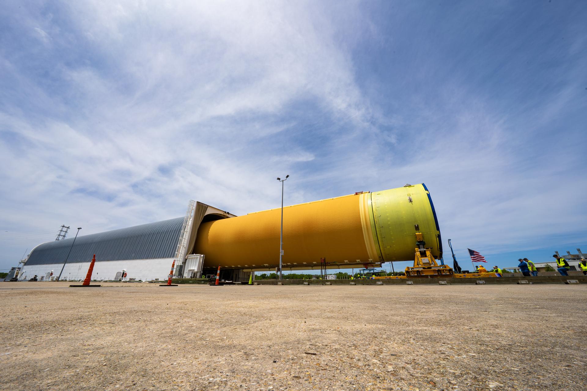
NASA moved the core stage, or the largest section, of the SLS (Space Launch System) rocket that will launch the crewed Artemis III mission in 2027 from the agency’s Michoud Assembly Facility to the agency’s Pegasus barge in New Orleans on April 20. The barge will ferry the top four-fifths – the section containing the liquid hydrogen tank, liquid oxygen tank, intertank, and forward skirt – of the SLS core stage to NASA’s Kennedy Space Center in Florida to complete outfitting and vertical integration. Teams with NASA and Boeing, the SLS core stage lead contractor, used specialized transporters to guide the top four-fifths from the NASA rocket factory to Pegasus. Prior to the move, technicians added an engine section transportation simulator to the rocket stage for shipment to the Space Coast. Next year’s Artemis III mission will launch astronauts to Earth’s orbit aboard the Orion spacecraft on top of SLS to test rendezvous and docking capabilities between Orion and commercial spacecraft needed to land Artemis IV astronauts on the Moon in 2028. NASA’s SLS is the only rocket capable of sending Orion, astronauts, and supplies to the Moon in a single launch.

NASA moved the core stage, or the largest section, of the SLS (Space Launch System) rocket that will launch the crewed Artemis III mission in 2027 from the agency’s Michoud Assembly Facility to the agency’s Pegasus barge in New Orleans on April 20. The barge will ferry the top four-fifths – the section containing the liquid hydrogen tank, liquid oxygen tank, intertank, and forward skirt – of the SLS core stage to NASA’s Kennedy Space Center in Florida to complete outfitting and vertical integration. Teams with NASA and Boeing, the SLS core stage lead contractor, used specialized transporters to guide the top four-fifths from the NASA rocket factory to Pegasus. Prior to the move, technicians added an engine section transportation simulator to the rocket stage for shipment to the Space Coast. Next year’s Artemis III mission will launch astronauts to Earth’s orbit aboard the Orion spacecraft on top of SLS to test rendezvous and docking capabilities between Orion and commercial spacecraft needed to land Artemis IV astronauts on the Moon in 2028. NASA’s SLS is the only rocket capable of sending Orion, astronauts, and supplies to the Moon in a single launch.
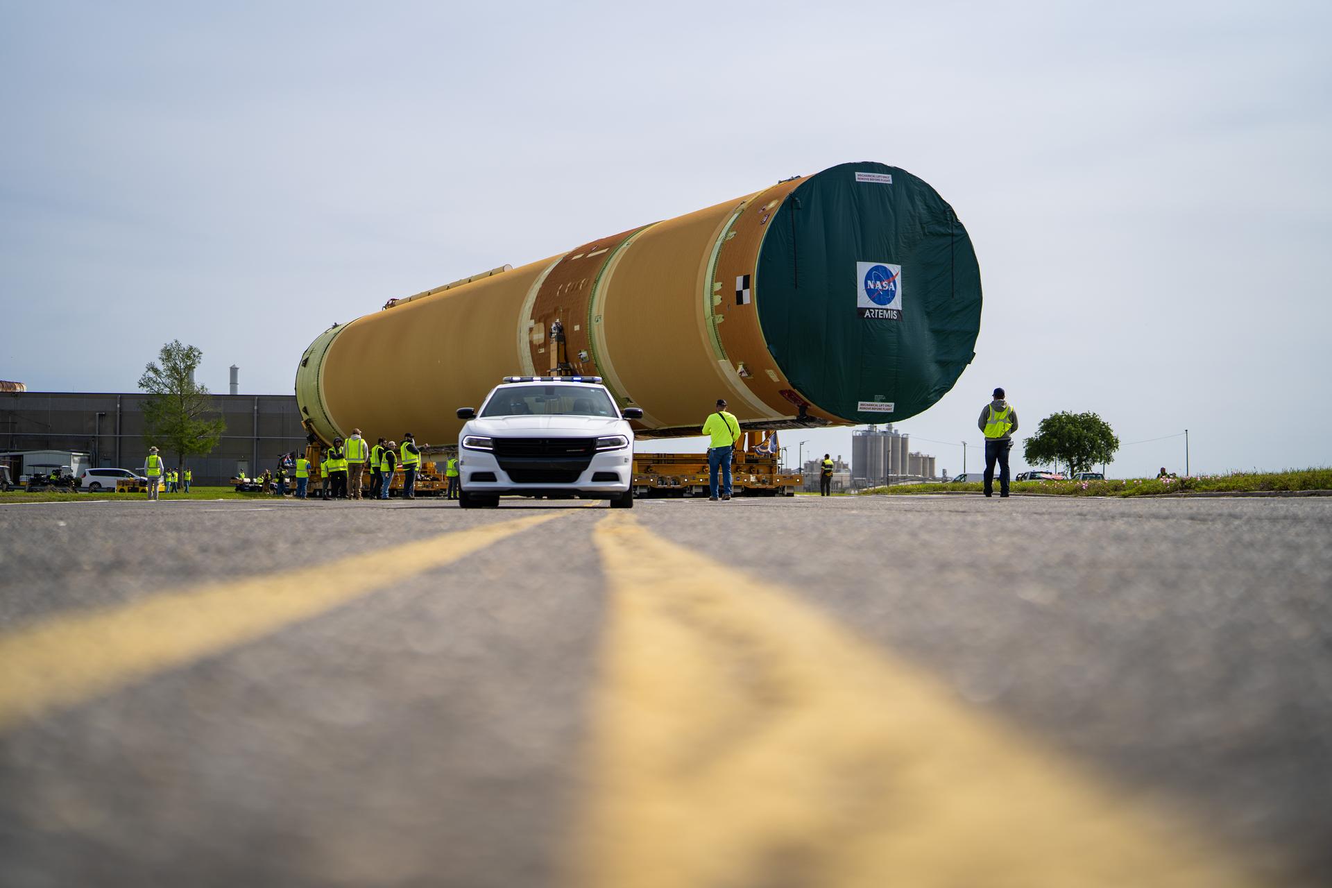
NASA moved the core stage, or the largest section, of the SLS (Space Launch System) rocket that will launch the crewed Artemis III mission in 2027 from the agency’s Michoud Assembly Facility to the agency’s Pegasus barge in New Orleans on April 20. The barge will ferry the top four-fifths – the section containing the liquid hydrogen tank, liquid oxygen tank, intertank, and forward skirt – of the SLS core stage to NASA’s Kennedy Space Center in Florida to complete outfitting and vertical integration. Teams with NASA and Boeing, the SLS core stage lead contractor, used specialized transporters to guide the top four-fifths from the NASA rocket factory to Pegasus. Prior to the move, technicians added an engine section transportation simulator to the rocket stage for shipment to the Space Coast. Next year’s Artemis III mission will launch astronauts to Earth’s orbit aboard the Orion spacecraft on top of SLS to test rendezvous and docking capabilities between Orion and commercial spacecraft needed to land Artemis IV astronauts on the Moon in 2028. NASA’s SLS is the only rocket capable of sending Orion, astronauts, and supplies to the Moon in a single launch.
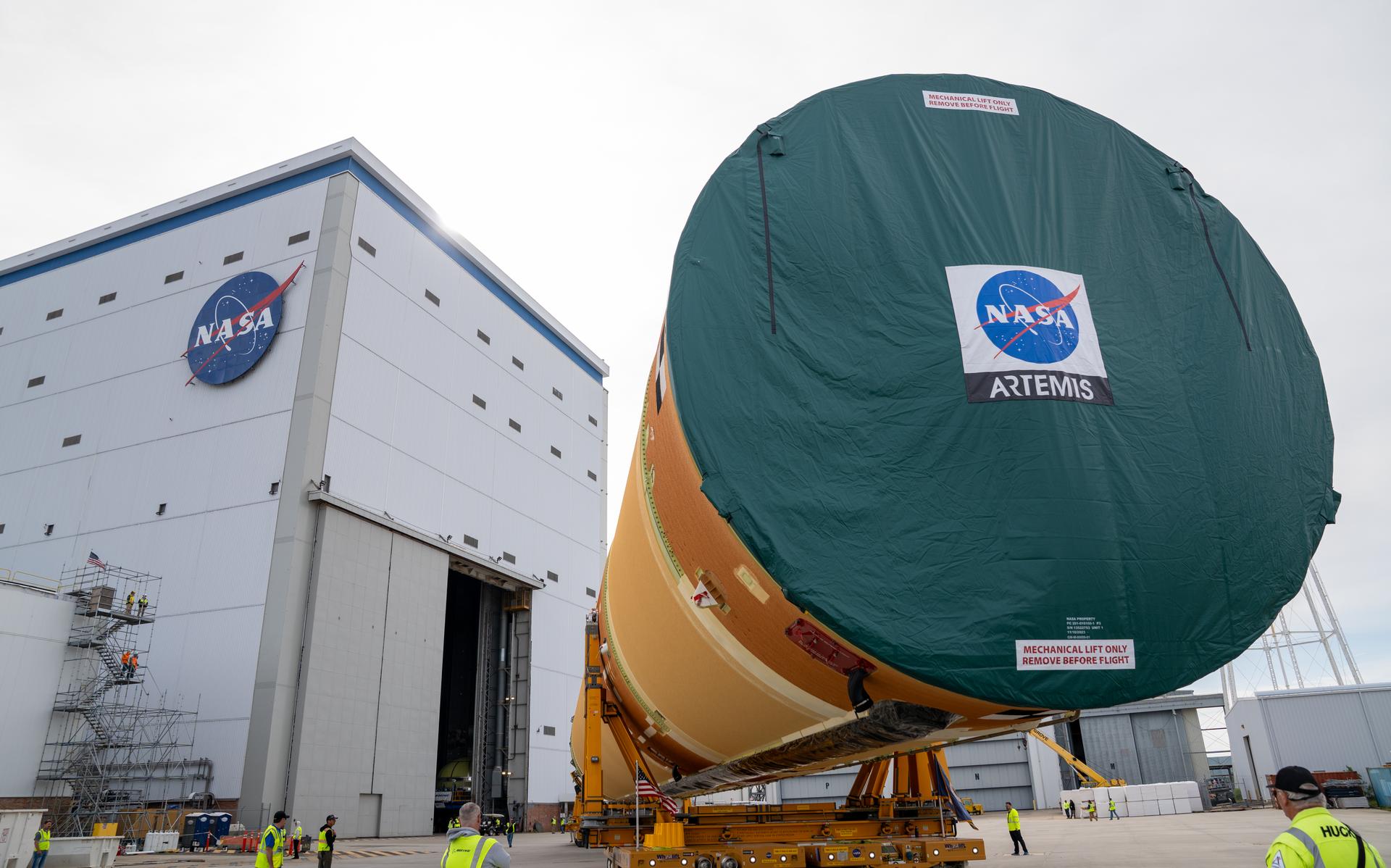
NASA moved the core stage, or the largest section, of the SLS (Space Launch System) rocket that will launch the crewed Artemis III mission in 2027 from the agency’s Michoud Assembly Facility to the agency’s Pegasus barge in New Orleans on April 20. The barge will ferry the top four-fifths – the section containing the liquid hydrogen tank, liquid oxygen tank, intertank, and forward skirt – of the SLS core stage to NASA’s Kennedy Space Center in Florida to complete outfitting and vertical integration. Teams with NASA and Boeing, the SLS core stage lead contractor, used specialized transporters to guide the top four-fifths from the NASA rocket factory to Pegasus. Prior to the move, technicians added an engine section transportation simulator to the rocket stage for shipment to the Space Coast. Next year’s Artemis III mission will launch astronauts to Earth’s orbit aboard the Orion spacecraft on top of SLS to test rendezvous and docking capabilities between Orion and commercial spacecraft needed to land Artemis IV astronauts on the Moon in 2028. NASA’s SLS is the only rocket capable of sending Orion, astronauts, and supplies to the Moon in a single launch. Photo Credit: (NASA/Brandon Hancock)
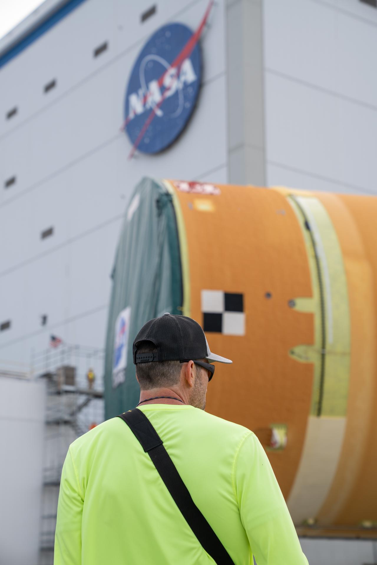
NASA moved the core stage, or the largest section, of the SLS (Space Launch System) rocket that will launch the crewed Artemis III mission in 2027 from the agency’s Michoud Assembly Facility to the agency’s Pegasus barge in New Orleans on April 20. The barge will ferry the top four-fifths – the section containing the liquid hydrogen tank, liquid oxygen tank, intertank, and forward skirt – of the SLS core stage to NASA’s Kennedy Space Center in Florida to complete outfitting and vertical integration. Teams with NASA and Boeing, the SLS core stage lead contractor, used specialized transporters to guide the top four-fifths from the NASA rocket factory to Pegasus. Prior to the move, technicians added an engine section transportation simulator to the rocket stage for shipment to the Space Coast. Next year’s Artemis III mission will launch astronauts to Earth’s orbit aboard the Orion spacecraft on top of SLS to test rendezvous and docking capabilities between Orion and commercial spacecraft needed to land Artemis IV astronauts on the Moon in 2028. NASA’s SLS is the only rocket capable of sending Orion, astronauts, and supplies to the Moon in a single launch. Photo Credit: (NASA/Brandon Hancock)

NASA moved the core stage, or the largest section, of the SLS (Space Launch System) rocket that will launch the crewed Artemis III mission in 2027 from the agency’s Michoud Assembly Facility to the agency’s Pegasus barge in New Orleans on April 20. The barge will ferry the top four-fifths – the section containing the liquid hydrogen tank, liquid oxygen tank, intertank, and forward skirt – of the SLS core stage to NASA’s Kennedy Space Center in Florida to complete outfitting and vertical integration. Teams with NASA and Boeing, the SLS core stage lead contractor, used specialized transporters to guide the top four-fifths from the NASA rocket factory to Pegasus. Prior to the move, technicians added an engine section transportation simulator to the rocket stage for shipment to the Space Coast. Next year’s Artemis III mission will launch astronauts to Earth’s orbit aboard the Orion spacecraft on top of SLS to test rendezvous and docking capabilities between Orion and commercial spacecraft needed to land Artemis IV astronauts on the Moon in 2028. NASA’s SLS is the only rocket capable of sending Orion, astronauts, and supplies to the Moon in a single launch. Photo Credit: (NASA/Brandon Hancock)
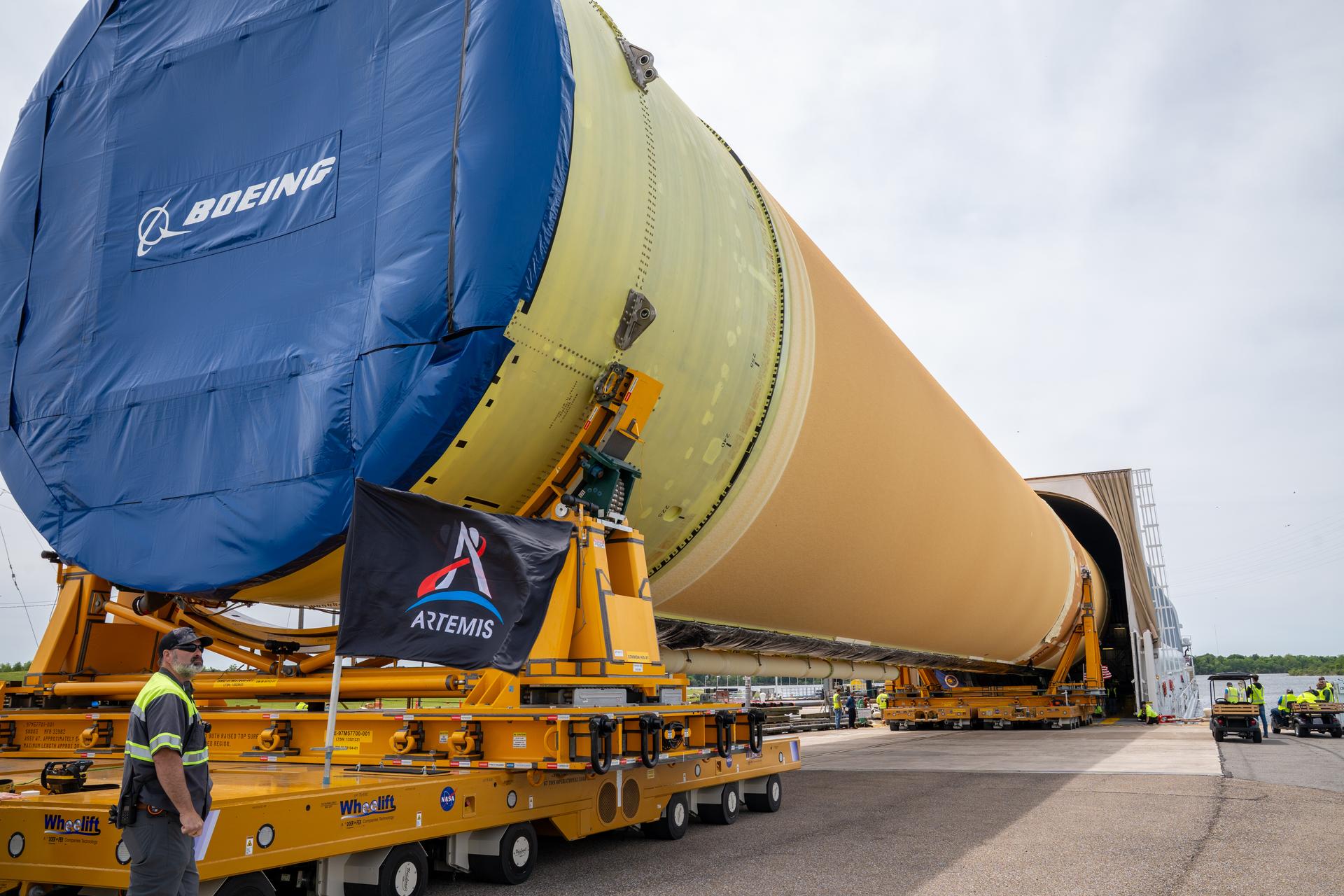
NASA moved the core stage, or the largest section, of the SLS (Space Launch System) rocket that will launch the crewed Artemis III mission in 2027 from the agency’s Michoud Assembly Facility to the agency’s Pegasus barge in New Orleans on April 20. The barge will ferry the top four-fifths – the section containing the liquid hydrogen tank, liquid oxygen tank, intertank, and forward skirt – of the SLS core stage to NASA’s Kennedy Space Center in Florida to complete outfitting and vertical integration. Teams with NASA and Boeing, the SLS core stage lead contractor, used specialized transporters to guide the top four-fifths from the NASA rocket factory to Pegasus. Prior to the move, technicians added an engine section transportation simulator to the rocket stage for shipment to the Space Coast. Next year’s Artemis III mission will launch astronauts to Earth’s orbit aboard the Orion spacecraft on top of SLS to test rendezvous and docking capabilities between Orion and commercial spacecraft needed to land Artemis IV astronauts on the Moon in 2028. NASA’s SLS is the only rocket capable of sending Orion, astronauts, and supplies to the Moon in a single launch. Photo Credit: (NASA/Brandon Hancock)
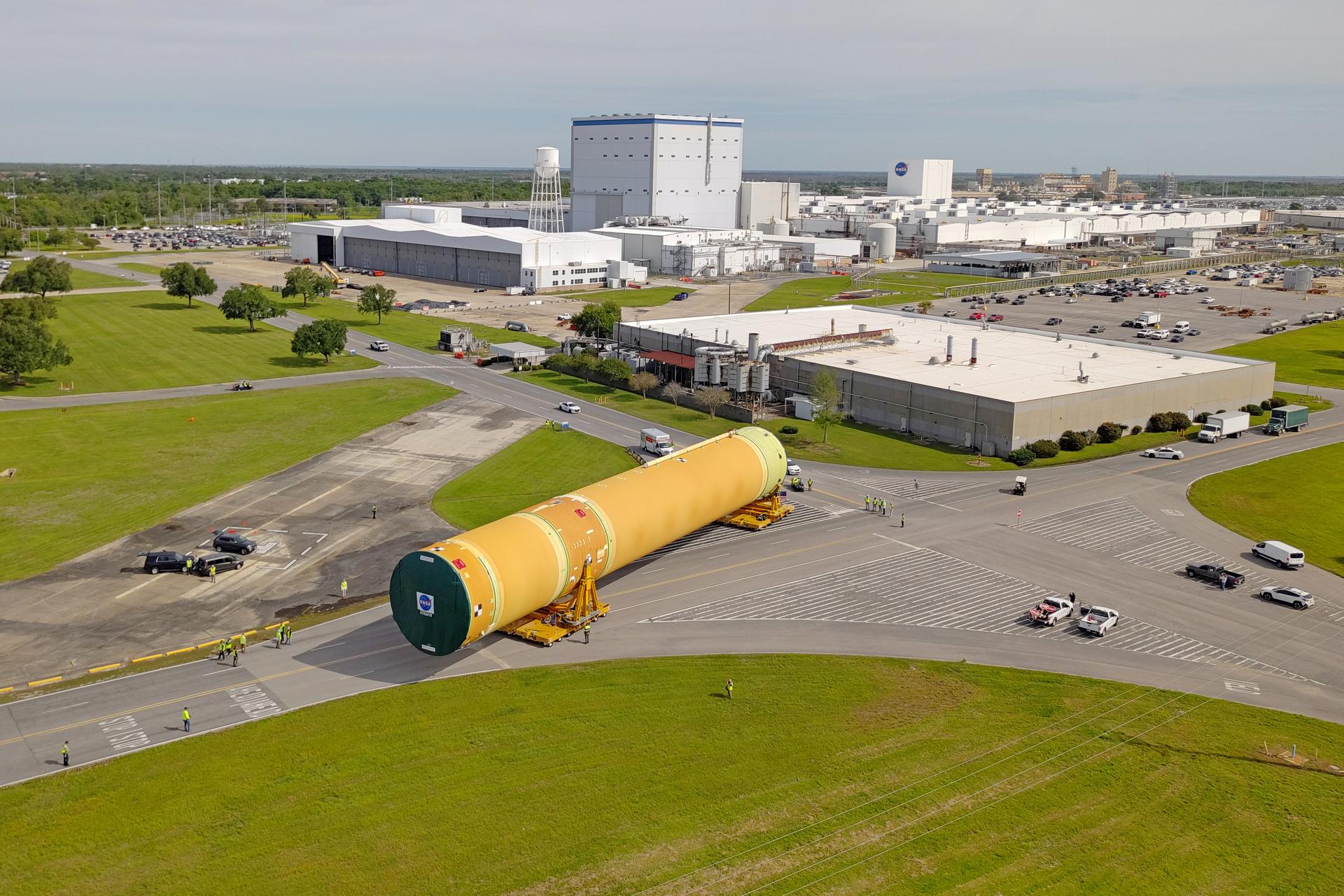
NASA moved the core stage, or the largest section, of the SLS (Space Launch System) rocket that will launch the crewed Artemis III mission in 2027 from the agency’s Michoud Assembly Facility to the agency’s Pegasus barge in New Orleans on April 20. The barge will ferry the top four-fifths – the section containing the liquid hydrogen tank, liquid oxygen tank, intertank, and forward skirt – of the SLS core stage to NASA’s Kennedy Space Center in Florida to complete outfitting and vertical integration. Teams with NASA and Boeing, the SLS core stage lead contractor, used specialized transporters to guide the top four-fifths from the NASA rocket factory to Pegasus. Prior to the move, technicians added an engine section transportation simulator to the rocket stage for shipment to the Space Coast. Next year’s Artemis III mission will launch astronauts to Earth’s orbit aboard the Orion spacecraft on top of SLS to test rendezvous and docking capabilities between Orion and commercial spacecraft needed to land Artemis IV astronauts on the Moon in 2028. NASA’s SLS is the only rocket capable of sending Orion, astronauts, and supplies to the Moon in a single launch.
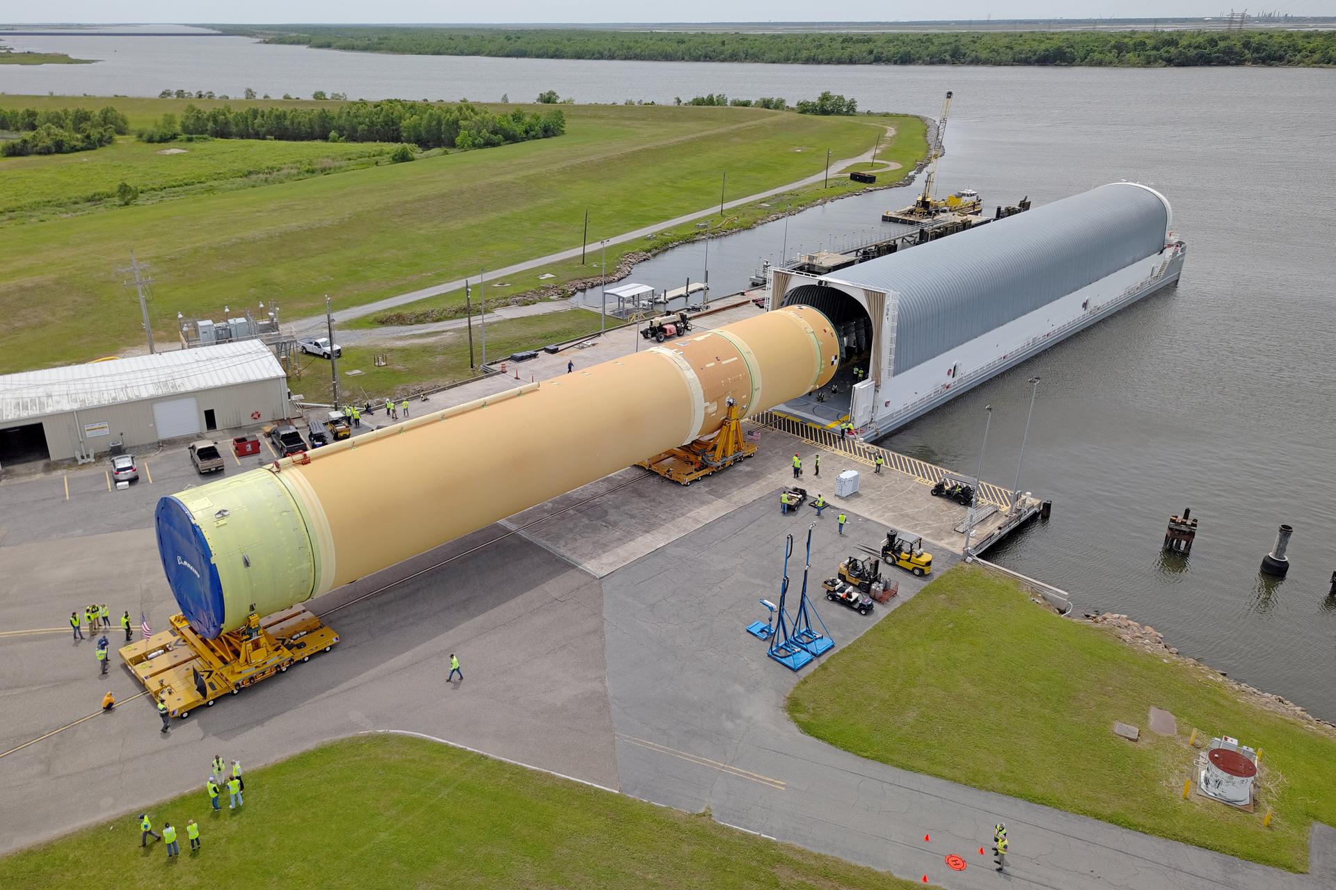
NASA moved the core stage, or the largest section, of the SLS (Space Launch System) rocket that will launch the crewed Artemis III mission in 2027 from the agency’s Michoud Assembly Facility to the agency’s Pegasus barge in New Orleans on April 20. The barge will ferry the top four-fifths – the section containing the liquid hydrogen tank, liquid oxygen tank, intertank, and forward skirt – of the SLS core stage to NASA’s Kennedy Space Center in Florida to complete outfitting and vertical integration. Teams with NASA and Boeing, the SLS core stage lead contractor, used specialized transporters to guide the top four-fifths from the NASA rocket factory to Pegasus. Prior to the move, technicians added an engine section transportation simulator to the rocket stage for shipment to the Space Coast. Next year’s Artemis III mission will launch astronauts to Earth’s orbit aboard the Orion spacecraft on top of SLS to test rendezvous and docking capabilities between Orion and commercial spacecraft needed to land Artemis IV astronauts on the Moon in 2028. NASA’s SLS is the only rocket capable of sending Orion, astronauts, and supplies to the Moon in a single launch.
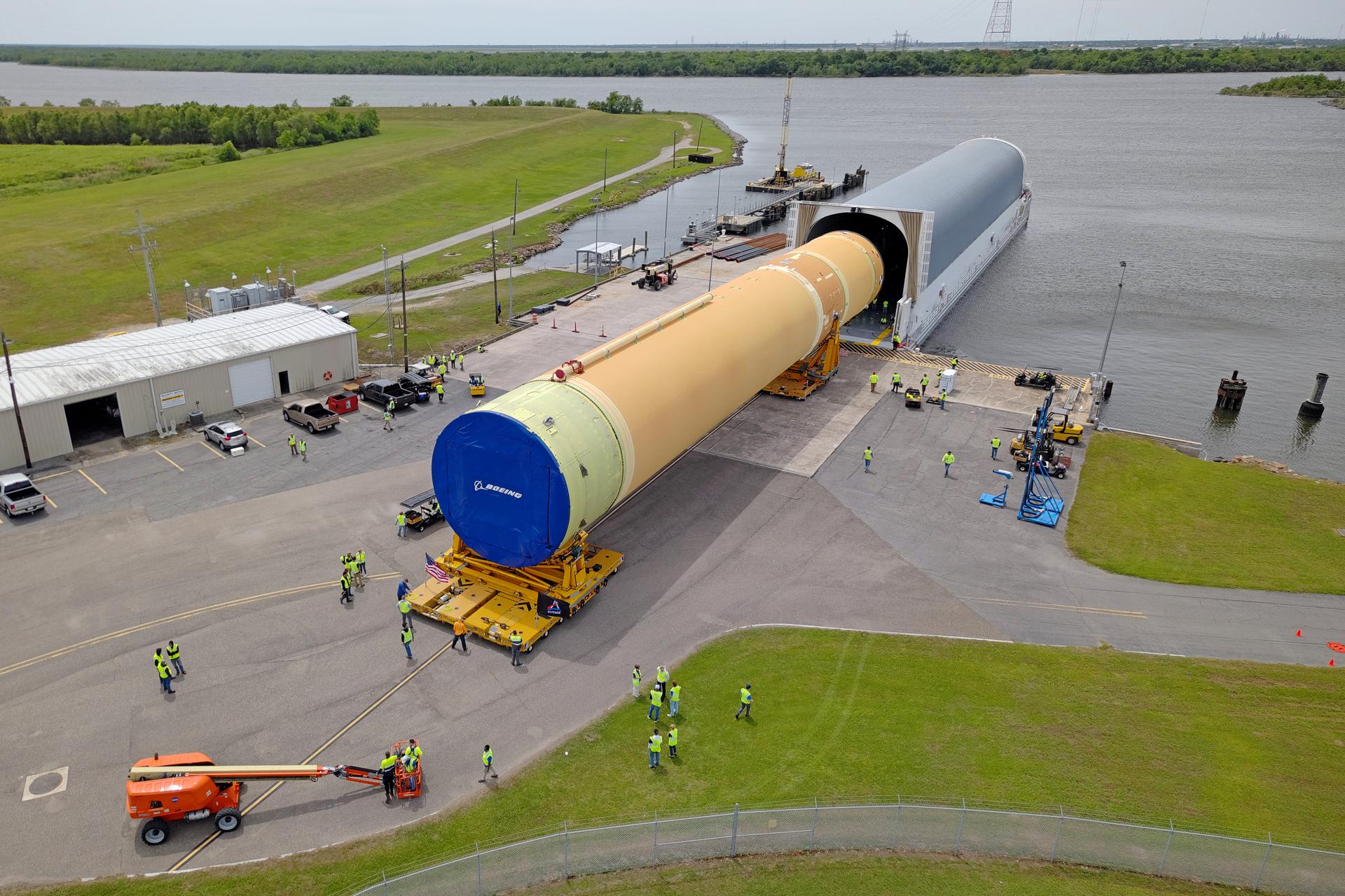
NASA moved the core stage, or the largest section, of the SLS (Space Launch System) rocket that will launch the crewed Artemis III mission in 2027 from the agency’s Michoud Assembly Facility to the agency’s Pegasus barge in New Orleans on April 20. The barge will ferry the top four-fifths – the section containing the liquid hydrogen tank, liquid oxygen tank, intertank, and forward skirt – of the SLS core stage to NASA’s Kennedy Space Center in Florida to complete outfitting and vertical integration. Teams with NASA and Boeing, the SLS core stage lead contractor, used specialized transporters to guide the top four-fifths from the NASA rocket factory to Pegasus. Prior to the move, technicians added an engine section transportation simulator to the rocket stage for shipment to the Space Coast. Next year’s Artemis III mission will launch astronauts to Earth’s orbit aboard the Orion spacecraft on top of SLS to test rendezvous and docking capabilities between Orion and commercial spacecraft needed to land Artemis IV astronauts on the Moon in 2028. NASA’s SLS is the only rocket capable of sending Orion, astronauts, and supplies to the Moon in a single launch. Image credit: NASA/Michael DeMocker
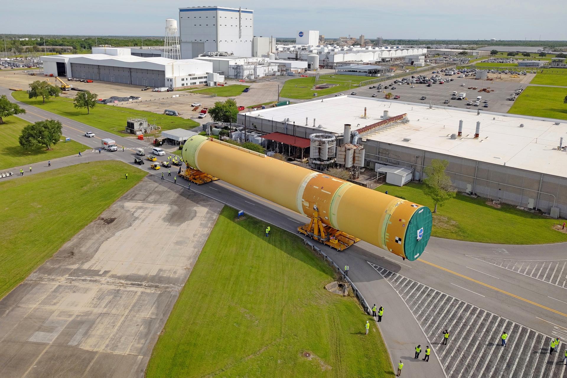
NASA moved the core stage, or the largest section, of the SLS (Space Launch System) rocket that will launch the crewed Artemis III mission in 2027 from the agency’s Michoud Assembly Facility to the agency’s Pegasus barge in New Orleans on April 20. The barge will ferry the top four-fifths – the section containing the liquid hydrogen tank, liquid oxygen tank, intertank, and forward skirt – of the SLS core stage to NASA’s Kennedy Space Center in Florida to complete outfitting and vertical integration. Teams with NASA and Boeing, the SLS core stage lead contractor, used specialized transporters to guide the top four-fifths from the NASA rocket factory to Pegasus. Prior to the move, technicians added an engine section transportation simulator to the rocket stage for shipment to the Space Coast. Next year’s Artemis III mission will launch astronauts to Earth’s orbit aboard the Orion spacecraft on top of SLS to test rendezvous and docking capabilities between Orion and commercial spacecraft needed to land Artemis IV astronauts on the Moon in 2028. NASA’s SLS is the only rocket capable of sending Orion, astronauts, and supplies to the Moon in a single launch. Image credit: NASA/Michael DeMocker
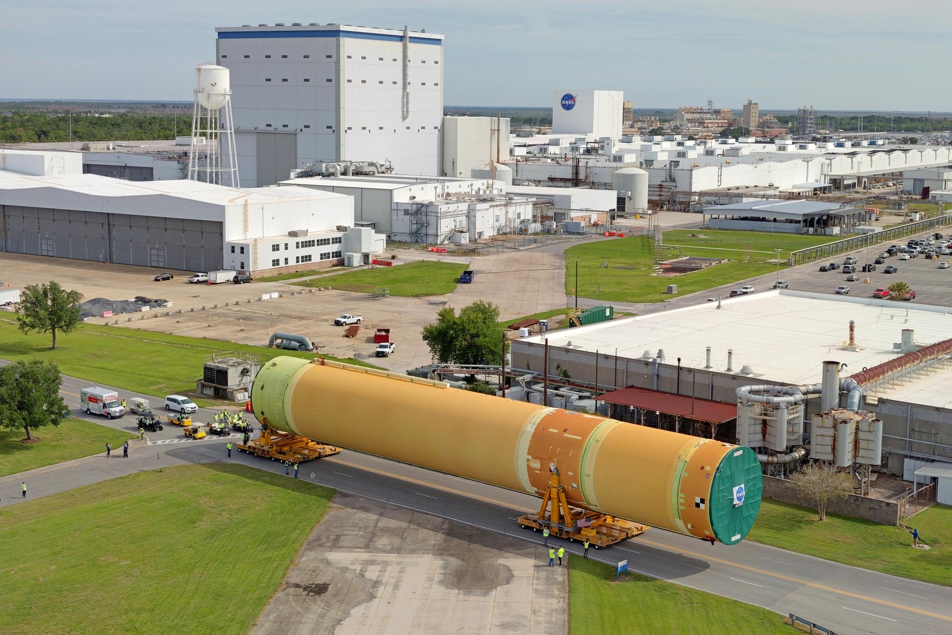
NASA moved the core stage, or the largest section, of the SLS (Space Launch System) rocket that will launch the crewed Artemis III mission in 2027 from the agency’s Michoud Assembly Facility to the agency’s Pegasus barge in New Orleans on April 20. The barge will ferry the top four-fifths – the section containing the liquid hydrogen tank, liquid oxygen tank, intertank, and forward skirt – of the SLS core stage to NASA’s Kennedy Space Center in Florida to complete outfitting and vertical integration. Teams with NASA and Boeing, the SLS core stage lead contractor, used specialized transporters to guide the top four-fifths from the NASA rocket factory to Pegasus. Prior to the move, technicians added an engine section transportation simulator to the rocket stage for shipment to the Space Coast. Next year’s Artemis III mission will launch astronauts to Earth’s orbit aboard the Orion spacecraft on top of SLS to test rendezvous and docking capabilities between Orion and commercial spacecraft needed to land Artemis IV astronauts on the Moon in 2028. NASA’s SLS is the only rocket capable of sending Orion, astronauts, and supplies to the Moon in a single launch. Image credit: NASA/Michael DeMocker
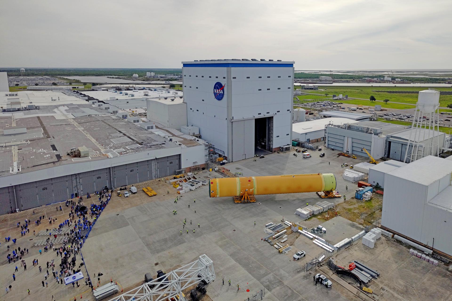
NASA moved the core stage, or the largest section, of the SLS (Space Launch System) rocket that will launch the crewed Artemis III mission in 2027 from the agency’s Michoud Assembly Facility to the agency’s Pegasus barge in New Orleans on April 20. The barge will ferry the top four-fifths – the section containing the liquid hydrogen tank, liquid oxygen tank, intertank, and forward skirt – of the SLS core stage to NASA’s Kennedy Space Center in Florida to complete outfitting and vertical integration. Teams with NASA and Boeing, the SLS core stage lead contractor, used specialized transporters to guide the top four-fifths from the NASA rocket factory to Pegasus. Prior to the move, technicians added an engine section transportation simulator to the rocket stage for shipment to the Space Coast. Next year’s Artemis III mission will launch astronauts to Earth’s orbit aboard the Orion spacecraft on top of SLS to test rendezvous and docking capabilities between Orion and commercial spacecraft needed to land Artemis IV astronauts on the Moon in 2028. NASA’s SLS is the only rocket capable of sending Orion, astronauts, and supplies to the Moon in a single launch. Image credit: NASA/Michael DeMocker
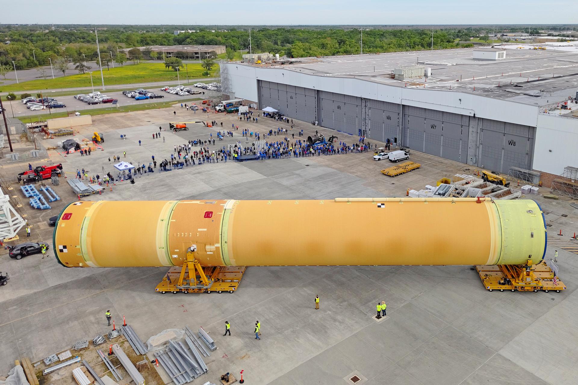
NASA moved the core stage, or the largest section, of the SLS (Space Launch System) rocket that will launch the crewed Artemis III mission in 2027 from the agency’s Michoud Assembly Facility to the agency’s Pegasus barge in New Orleans on April 20. The barge will ferry the top four-fifths – the section containing the liquid hydrogen tank, liquid oxygen tank, intertank, and forward skirt – of the SLS core stage to NASA’s Kennedy Space Center in Florida to complete outfitting and vertical integration. Teams with NASA and Boeing, the SLS core stage lead contractor, used specialized transporters to guide the top four-fifths from the NASA rocket factory to Pegasus. Prior to the move, technicians added an engine section transportation simulator to the rocket stage for shipment to the Space Coast. Next year’s Artemis III mission will launch astronauts to Earth’s orbit aboard the Orion spacecraft on top of SLS to test rendezvous and docking capabilities between Orion and commercial spacecraft needed to land Artemis IV astronauts on the Moon in 2028. NASA’s SLS is the only rocket capable of sending Orion, astronauts, and supplies to the Moon in a single launch. Image credit: NASA/Michael DeMocker
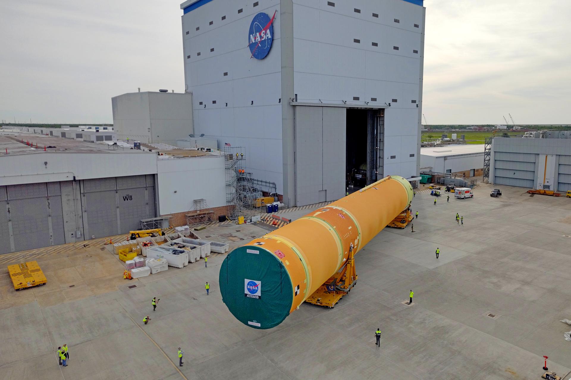
NASA moved the core stage, or the largest section, of the SLS (Space Launch System) rocket that will launch the crewed Artemis III mission in 2027 from the agency’s Michoud Assembly Facility to the agency’s Pegasus barge in New Orleans on April 20. The barge will ferry the top four-fifths – the section containing the liquid hydrogen tank, liquid oxygen tank, intertank, and forward skirt – of the SLS core stage to NASA’s Kennedy Space Center in Florida to complete outfitting and vertical integration. Teams with NASA and Boeing, the SLS core stage lead contractor, used specialized transporters to guide the top four-fifths from the NASA rocket factory to Pegasus. Prior to the move, technicians added an engine section transportation simulator to the rocket stage for shipment to the Space Coast. Next year’s Artemis III mission will launch astronauts to Earth’s orbit aboard the Orion spacecraft on top of SLS to test rendezvous and docking capabilities between Orion and commercial spacecraft needed to land Artemis IV astronauts on the Moon in 2028. NASA’s SLS is the only rocket capable of sending Orion, astronauts, and supplies to the Moon in a single launch. Image credit: NASA/Michael DeMocker
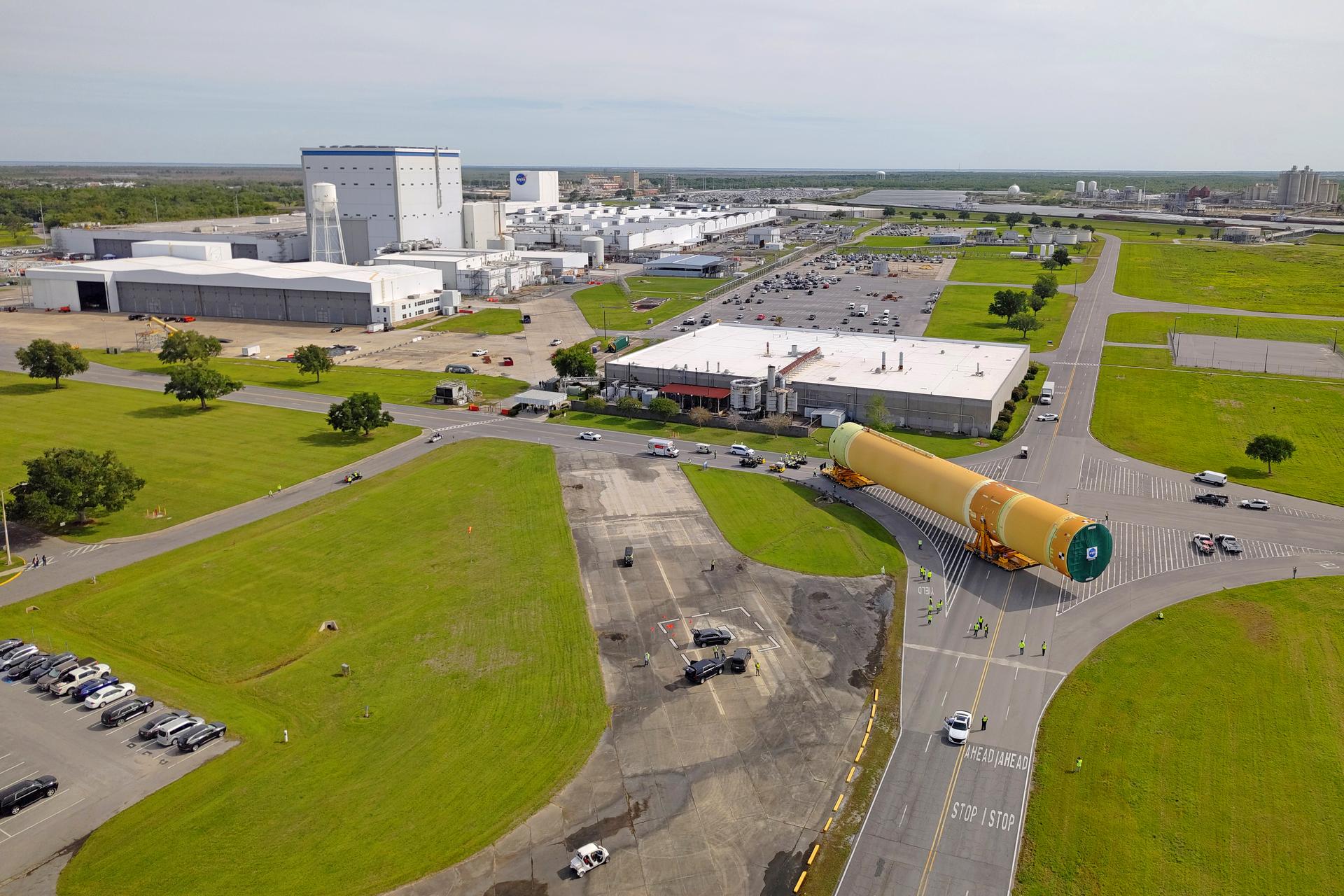
NASA moved the core stage, or the largest section, of the SLS (Space Launch System) rocket that will launch the crewed Artemis III mission in 2027 from the agency’s Michoud Assembly Facility to the agency’s Pegasus barge in New Orleans on April 20. The barge will ferry the top four-fifths – the section containing the liquid hydrogen tank, liquid oxygen tank, intertank, and forward skirt – of the SLS core stage to NASA’s Kennedy Space Center in Florida to complete outfitting and vertical integration. Teams with NASA and Boeing, the SLS core stage lead contractor, used specialized transporters to guide the top four-fifths from the NASA rocket factory to Pegasus. Prior to the move, technicians added an engine section transportation simulator to the rocket stage for shipment to the Space Coast. Next year’s Artemis III mission will launch astronauts to Earth’s orbit aboard the Orion spacecraft on top of SLS to test rendezvous and docking capabilities between Orion and commercial spacecraft needed to land Artemis IV astronauts on the Moon in 2028. NASA’s SLS is the only rocket capable of sending Orion, astronauts, and supplies to the Moon in a single launch. Image credit: NASA/Michael DeMocker
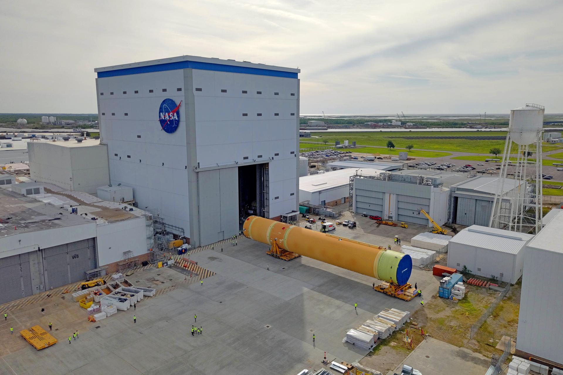
NASA moved the core stage, or the largest section, of the SLS (Space Launch System) rocket that will launch the crewed Artemis III mission in 2027 from the agency’s Michoud Assembly Facility to the agency’s Pegasus barge in New Orleans on April 20. The barge will ferry the top four-fifths – the section containing the liquid hydrogen tank, liquid oxygen tank, intertank, and forward skirt – of the SLS core stage to NASA’s Kennedy Space Center in Florida to complete outfitting and vertical integration. Teams with NASA and Boeing, the SLS core stage lead contractor, used specialized transporters to guide the top four-fifths from the NASA rocket factory to Pegasus. Prior to the move, technicians added an engine section transportation simulator to the rocket stage for shipment to the Space Coast. Next year’s Artemis III mission will launch astronauts to Earth’s orbit aboard the Orion spacecraft on top of SLS to test rendezvous and docking capabilities between Orion and commercial spacecraft needed to land Artemis IV astronauts on the Moon in 2028. NASA’s SLS is the only rocket capable of sending Orion, astronauts, and supplies to the Moon in a single launch. Image credit: NASA/Michael DeMocker
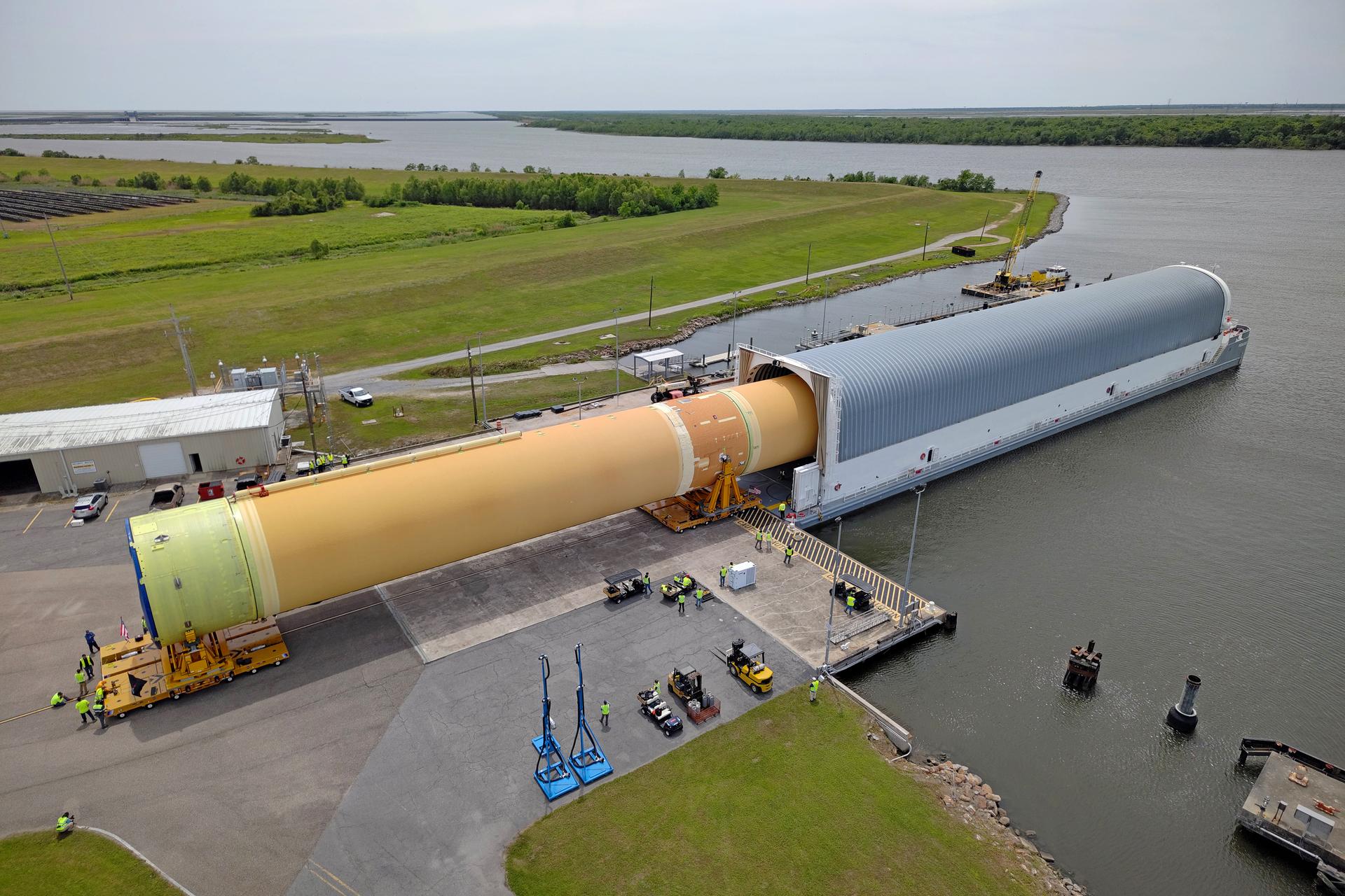
NASA moved the core stage, or the largest section, of the SLS (Space Launch System) rocket that will launch the crewed Artemis III mission in 2027 from the agency’s Michoud Assembly Facility to the agency’s Pegasus barge in New Orleans on April 20. The barge will ferry the top four-fifths – the section containing the liquid hydrogen tank, liquid oxygen tank, intertank, and forward skirt – of the SLS core stage to NASA’s Kennedy Space Center in Florida to complete outfitting and vertical integration. Teams with NASA and Boeing, the SLS core stage lead contractor, used specialized transporters to guide the top four-fifths from the NASA rocket factory to Pegasus. Prior to the move, technicians added an engine section transportation simulator to the rocket stage for shipment to the Space Coast. Next year’s Artemis III mission will launch astronauts to Earth’s orbit aboard the Orion spacecraft on top of SLS to test rendezvous and docking capabilities between Orion and commercial spacecraft needed to land Artemis IV astronauts on the Moon in 2028. NASA’s SLS is the only rocket capable of sending Orion, astronauts, and supplies to the Moon in a single launch. Image credit: NASA/Michael DeMocker