Dutch Netherlands testing of Boeing 360 Vertol Rotor: Full Test
Full test of the Boeing 360 Vertol Rotor.
3/4 front view of Lockheed Rigid Rotor model in Ames 40x80 foot wind Tunnel.
Lockheed Rigid Rotor Model in Ames 40x80 Foot Wind Tunnel.
3/4 front view of the Lockheed Stopped Rotor with blades unfolded. Charles Greco and Ed Verrette in photo.
Lockheed Stopped Rotor in the Ames 40x80 Foot Wind Tunnel.
One of the first helicopter tests in the 40 x 80 wind tunnel.  John McCloud, pictured, started helicopter work in the 40 x 80.  Test 150. Testing the effects of camber on rotor blades.
Rotor Blade Test in the NACA Ames 40x80 foot Wind Tunnel.
(Oct. 27 1976) Controllable Twist Rotor, 40x80 Foot Wind Tunnel at Ames Research Center, model With John Bolt.
Controllable Twist Rotor, 40x80 Foot Wind Tunnel at Ames Research Center.
Top Plan view of Bell Rotor with Ed Verrett left frame. Test #437.
Bell Helicopter Rotor Test in the Ames 40x80 foot wind tunnel.
The XV-15 tilt rotor ships #1 and #2 parked on the NASA Dryden Flight Research Center ramp. The XV-15s, manufactured by Bell, were involved in limited research at Dryden in 1980 and 1981. The development of the XV-15 Tiltrotor research aircraft was initiated in 1973 with joint Army/NASA funding as a "proof of concept", or "technology demonstrator" program, with two aircraft being built by Bell Helicopter Textron (BHT) in 1977.  The aircraft are powered by twin Lycoming T-53 turboshaft engines that are connected by a cross-shaft and drive three-bladed, 25 ft diameter metal rotors (the size extensively tested in a wind tunnel). The engines and main transmissions are located in wingtip nacelles to minimize the operational loads on the cross-shaft system and, with the rotors, tilt as a single unit.  For takeoff, the proprotors and their engines are used in the straight-up position where the thrust is directed downward. The XV-15 then climbs vertically into the air like a helicopter. In this VTOL mode, the vehicle can lift off and hover for approximately one hour.  Once off the ground, the XV-15 has the ability to fly in one of two different modes. It can fly as a helicopter, in the partially converted airplane mode. The XV-15 can also then convert from the helicopter mode to the airplane mode. This is accomplished by continuous rotation of the proprotors from the helicopter rotor position to the conventional airplane propeller position. During the ten to fifteen second conversion period, the aircraft speed increases and lift is transferred from the rotors to the wing. To land, the proprotors are rotated up to the helicopter rotor position and flown as a helicopter to a vertical landing.
XV-15 tilt rotor ship #1 and #2 parked on NASA ramp
3/4 front view of Lockheed Stopped Rotor.
Lockheed Stopped Rotor.
Dutch Netherlands testing of Boeing 360 Vertol Rotor: Full Test
Full test of the Boeing 360 Vertol Rotor
Lockheed XH-51 Experimental Rigid Rotors, no hinges, in Ames 40x80 foot wind tunnel. John McCloud (left sitting) Jack Rabbot (Right).
Lockheed XH-51 Helicopter with Experimental Rigid Rotors in the 40x80 Foot Wind Tunnel at NASA Ames.
Experimental investigation of boundary-layer control to helicopter rotor blades to increase forward speed capabilities. 3/4 front view. Shaft angle - 35deg.  John Mc.Cloud in picture. He was a good guy.
Boundary-Layer Control to Helicopter Rotor Blades.
JVX/ATB Rotor Blade Project: Bell Boeing Rotor for the XV-15 tilt rotor Research Aircraft (TRRA)
ARC-1976-AC84-0176-26
JVX/ATB Rotor Blade Project: Bell Boeing Rotor for the XV-15 tilt rotor Research Aircraft (TRRA)
ARC-1976-AC84-0176-21
JVX/ATB Rotor Blade Project: Bell Boeing Rotor for the XV-15 tilt rotor Research Aircraft (TRRA)
ARC-1976-AC84-0176-22
Experimental investigation of boundary layer control to helicopter rotor blades to increase forward speed capabilities. 3/4 overhead view. Shaft angle - 35deg.
Investigation of Boundary Layer Control to Helicopter Rotor Blades.
JVX/ATB Rotor Blade Project: Bell Boeing Rotor for the XV-15 tilt rotor Research Aircraft (TRRA) and test crew in front of the OARF
ARC-1976-AC84-0176-20
NASA's Ingenuity Mars Helicopter used its black-and-white navigation camera to capture this video showing the shadows of its rotor blades turning on Feb. 11, 2024. Engineers planned the video to get more information about damage that was sustained by the rotor blades after a rough landing occurred during the helicopter's 72nd flight on Jan. 18, 2024.  This video shows that Ingenuity's upper rotor, the first rotor seen in this video, has a rotor blade missing. The blade appears to have separated near the mast.   Video available at https://photojournal.jpl.nasa.gov/catalog/PIA26244
Ingenuity's Navcam Reveals a Missing Rotor Blade
3/4 lower rear view of Controllable Twist Rotor (CTR) test of 4 blade helicopter model. Pictures with Ben Mandwyler Andy Lemnios, in 40x80 foot wind tunnel. Small flaps on rotor blades.
Controllable Twist Rotor in 40x80 Foot Wind Tunnel at Ames.
Bell-Boeing Tilt Rotor V-22 Osprey in flight.
ARC-1989-AC89-0246-8
Bell Helicopter Bell-Boeing Tilt Rotor V-22 Osprey in flight.
ARC-1989-AC89-0246-7
Bell Helicopter Bell-Boeing Tilt Rotor V-22 Ospreys in flight.
ARC-1989-AC89-0246-10
3/4 lower front view of Controllable Twist Rotor (CTR) test of 4 blade helicopter model.  Pictures with Ben Mandwyler Andy Lemnios, John McCloud (wheel chair), in 40x80 foot wind tunnel.  Small flaps on rotor blades.
Controllable Twist Rotor in 40x80 Foot Wind Tunnel at Ames.
Bell Boeing (Military) Tilt Rotor V-22 Osprey hovering at Bell Boeing Helicopter, Arlington TX
ARC-1989-AC89-0246-5
Bell Boeing (Military) Tilt Rotor V-22 Osprey hovering at Bell Boeing Helicopter, Arlington TX
ARC-1989-AC89-0246-2
After its 72nd flight on Jan. 18, 2024, NASA's Ingenuity Mars Helicopter captured this color image showing the shadow of a rotor blade damaged during a rough landing.  https://photojournal.jpl.nasa.gov/catalog/PIA26243
Ingenuity Spots the Shadow of Its Damaged Rotor Blade
Overhead view of Bell XV-3 Convertiplane. First tilt rotor tested in the 40 x 80 wind tunnel.  Transition aerodynamics studied; shown in hover mode.
Overhead view of Bell XV-3 Convertiplane
A dual rotor system for the next generation of Mars helicopters is tested in the 25-Foot Space Simulator at NASA's Jet Propulsion Laboratory in Southern California on Sept.15, 2023. Over three weeks, the carbon-fiber blades were spun up at ever-higher speeds and greater pitch angles to see if they would remain intact as their tips approached supersonic speeds. Longer and stronger than those used on NASA's Ingenuity Mars Helicopter, the blades reached Mach 0.95 during the test.  The simulator's vacuum chamber allows engineers to test spacecraft and components in conditions like those they would face on Mars.  The inset at upper right shows the same test from the perspective of a second camera also located inside the chamber.  Movie available at https://photojournal.jpl.nasa.gov/catalog/PIA26079
Testing Next-Generation Mars Helicopter Rotors
An atmospheric probe model attached upside down to a quad rotor remotely piloted aircraft ascends with the Moon visible on Oct. 22, 2024. The quad rotor aircraft released the probe above Rogers Dry Lake, a flight area adjacent NASA’s Armstrong Flight Research Center in Edwards, California. The probe was designed and built at the center.
Atmospheric Probe Shows Promise in Test Flight
The Remote Microscopic Imager (RMI) camera aboard NASA's Perseverance Mars rover took these zoomed-in images of the Ingenuity Mars Helicopter and one of its rotor blades on Feb. 24, 2024, the 1,072nd Martian day, or sol, of the mission.  The mosaic shows the helicopter at right, standing at an angle near the apex of a sand ripple. About 49 feet (15 meters) to the west of the helicopter's location (just left of center in the image), a large portion of one of the helicopter's rotor blades lies on the surface. The Ingenuity team is considering a theory that the blade detached after the rotorcraft impacted the Martian surface at the conclusion of the helicopter's 72nd and final flight on Jan. 18, 2024.  This mosaic is made up of seven images taken by the RMI, which is part of the rover's SuperCam instrument. At the time these images were taken, the distance between the rover and helicopter was about 1,365 feet (415 meters). Each circular image has a field of view of 26 feet (7.8 meters) at this distance.  Able to spot a softball from nearly a mile away, the RMI allows scientists to take images of details from a long distance. It also provides fine details of nearby targets zapped by SuperCam's laser.  SuperCam is led by Los Alamos National Laboratory in New Mexico, where the instrument's body unit was developed. The mast unit, including the RMI used for these images, was developed and built by several laboratories of the CNRS (the French research center) and French universities under the contracting authority of Centre National d'Études Spatiales (CNES), the French space agency.  A key objective for Perseverance's mission on Mars is astrobiology, including the search for signs of ancient microbial life. The rover will characterize the planet's geology and past climate, pave the way for human exploration of the Red Planet, and be the first mission to collect and cache Martian rock and regolith (broken rock and dust).  Subsequent NASA missions, in cooperation with ESA (European Space Agency), would send spacecraft to Mars to collect these sealed samples from the surface and return them to Earth for in-depth analysis.  The Mars 2020 Perseverance mission is part of NASA's Moon to Mars exploration approach, which includes Artemis missions to the Moon that will help prepare for human exploration of the Red Planet.  https://photojournal.jpl.nasa.gov/catalog/PIA26238
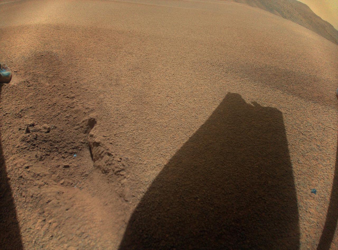
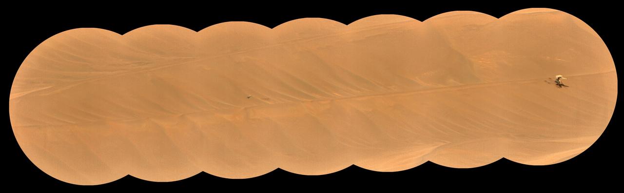
SuperCam's RMI Spots Ingenuity's Broken Rotor
An atmospheric probe model attached upside down to a host quad rotor remotely piloted aircraft lifts off on Oct. 22, 2024. The quad rotor aircraft released the probe above Rogers Dry Lake, a flight area adjacent NASA’s Armstrong Flight Research Center in Edwards, California. The probe was designed and built at the center.
Atmospheric Probe Shows Promise in Test Flight
An atmospheric probe model is attached upside down to a quad rotor remotely piloted aircraft on Oct. 22, 2024. The quad rotor aircraft released the probe above Rogers Dry Lake, a flight area adjacent NASA’s Armstrong Flight Research Center in Edwards, California. The probe was designed and built at the center.
Atmospheric Probe Shows Promise in Test Flight
Title: W-8 Fan Acoustic Casing Treatment Test on the Source Diagnostic Test Rotor Alone Hardware Program: Advanced Air Vehicles Program (AAVP) Project: Advanced Air Transport Technology (AATT) Sub-project: Aircraft Noise Reduction (ANR)   Weekly Highlight: ·         Acoustic Casing Treatment Testing Completed in the W-8 Single Stage Axial Compressor Facility: Testing of Acoustic Casing Treatments on the Source Diagnostic Test (SDT) rotor alone hardware which had begun in early January was completed on Thursday, February 16th. Four different over-the-rotor acoustic casing treatment concepts were tested along with two baseline configurations. Testing included steady-aerodynamic measurements of fan performance, hotfilm turbulence measurements, and inlet acoustic measurements with an in-duct array. These measurements will be used to assess the aerodynamic and acoustic impact of fan acoustic casing treatments on a high bypass ratio fan at TRL 3. This test was the last of 3 planned tests of potential over-the-rotor acoustic casing treatments. The first treatment test was completed in the Normal Incidence Tube (NIT) at Langley Research Center (LaRC) in Fall 2015 and the second was completed on the Advanced Noise Control Fan (ANCF) in the Aero-Acoustic Propulsion Laboratory (AAPL) in Winter 2016. This work is supported by the Aircraft Noise Reduction (ANR) subproject of the Advanced Air Transport Technology (AATT) Project. (POC: LTV/ Rick Bozak 3-5160)
Accoustic Casing Treatment Test
A quad rotor remotely piloted aircraft releases the atmospheric probe model above Rogers Dry Lake, a flight area adjacent NASA’s Armstrong Flight Research Center in Edwards, California, on Oct. 22, 2024. The probe was designed and built at the center.
Atmospheric Probe Shows Promise in Test Flight
Sikorsky Bearingless Main rotor (SBMR) mounted on the Ames Rotor Test Apparatus (RTA) during testing in the NASA Ames 40x80ft Subsonic Wind Tunnel, test-584. Rotors in motion.
ARC-1992-AC92-0323-138
Artwork: Bell Textron Co. Bell Textron Tilt Rotor  Folding Tilt Rotor Aircraft Concept
ARC-1987-AC87-0038-2
Sykorsky Bearingless Main Rotor test in 40x80ft w.t. (Full-Scale Rotor Test Apparatus)
ARC-1980-A80-0120
XV-15 Rotor Test Apparatus (RTA) flow visualization Hover test-80-0021 in 80x120ft w.t.  (rotor tip)
ARC-1996-AC96-0357-16
NASA Ames Graphics of LARGE-SCALE TILTING PROP ROTOR HOVER PERFORMANCE TESTS AMES OARF COMPOSITE.  (ref:  XV-15 Metal Rotor AC84-0176-13, XV-15 Composite Rotor from AC84-0498 series, V-22 Osprey AC84-0059-11 testing at OARF)
ARC-1987-AC87-0191
XV-3 HOVERING ON RAMP.  Flight Test of Bell XV-3 Convertiplane.  Bell VTOL tilt-rotor aircraft hovering in front of building N-211 at Moffett Field. The XV-3 design combined a helicopter rotor and a wing. A 450 horsepower Pratt & Whitney piston engine drove the two rotors. The XV-3, first flown in 1955 , was the first tilt-rotor to achieve 100% tilting of rotors. The vehicle was underpowered, however, and could not hover out of ground effect. Note the large ventral fin, which was added to imrpove directional stability in cruse (Oct 1962)
ARC-1959-AC-25685
XV-3 HOVERING ON RAMP.  Flight Test of Bell XV-3 Convertiplane.  Bell VTOL tilt-rotor aircraft hovering along side Hangar One at Moffett Field. The XV-3 design combined a helicopter rotor and a wing. A 450 horsepower Pratt & Whitney piston engine drove the two rotors. The XV-3, first flown in 1955 , was the first tilt-rotor to achieve 100% tilting of rotors. The vehicle was underpowered, however, and could not hover out of ground effect. Note the large ventral fin, which was added to imrpove directional stability in cruse (Oct 1962)
ARC-1959-A-25685-14
Sikorsky Bearingless Main rotor (SBMR) mounted on the Ames Rotor Test Apparatus (RTA) for testing in the NASA Ames40x80ft Subsonic Wind Tunnel, test-584.
ARC-1992-AC92-0323-119
Artwork: Bell Textron Co. Bell Textron Tilt Rotor  Forward Swept Wing Configuration  (Bell-029564 Swept Wing Tilt Rotor Concept)
ARC-1987-AC87-0038-1
Sikorsky Bearingless Main rotor (SBMR) mounted on the Ames Rotor Test Apparatus (RTA) for testing in the NASA Ames40x80ft Subsonic Wind Tunnel, test-584.
ARC-1992-AC92-0323-121
Sikorsky Bearingless Main rotor (SBMR) mounted on the Ames Rotor Test Apparatus (RTA) for testing in the NASA Ames40x80ft Subsonic Wind Tunnel, test-584.
ARC-1995-AC92-0323-128
HISTORICAL COLLECTION OF TILT ROTOR  Note: printed in NASA SP 2000-4517 The History of the XV-15 Tilt Rotor Research Aircraft; Concept to Flight
ARC-1998-A98-0209-2
Sikorsky Bearingless Main rotor (SBMR) mounted on the Ames Rotor Test Apparatus (RTA) for testing in the NASA Ames40x80ft Subsonic Wind Tunnel, test-584.
ARC-1992-AC92-0323-117
Russian Search and Rescue helicopter tail rotors are seen as teams wait to take off from Kustanay, Kazakhstan to support the Soyuz TMA-13M spacecraft landing with Expedition 41 Commander Max Suraev of the Russian Federal Space Agency (Roscosmos), NASA Flight Engineer Reid Wiseman and Flight Engineer Alexander Gerst of the European Space Agency (ESA) on Monday, Nov. 10, 2014. Suraev, Wiseman and Gerst returned to Earth after more than five months onboard the International Space Station where they served as members of the Expedition 40 and 41 crews. Photo Credit: (NASA/Bill Ingalls)
Expedition 41 Soyuz TMA-13M Landing
The atmospheric probe, right, flew after release from a quad rotor remotely piloted aircraft, left, on Oct. 22, 2024, above Rogers Dry Lake, a flight area adjacent to NASA’s Armstrong Flight Research Center in Edwards, California. The probe was designed and built at the center.
Atmospheric Probe Shows Promise in Test Flight
The atmospheric probe model flies free after release from a quad rotor remotely piloted aircraft above Rogers Dry Lake, a flight area adjacent NASA’s Armstrong Flight Research Center in Edwards, California, on Oct. 22, 2024. The probe was designed and built at the center.
Atmospheric Probe Shows Promise in Test Flight
Artwork: Bell Textron Co. Bell Textron Tilt Rotor folding swept wing and Forward Swept Wing Configurations (Bell-030355 Military High Speed Tilt Rotor)
ARC-1987-AC87-0038-3
Sikorsky Bearingless Main rotor (SBMR) mounted on the Ames Rotor Test Apparatus (RTA) for testing in the NASA Ames 40x80ft Subsonic Wind Tunnel, test-584. Shown with NASA engineer Bob McMahon
ARC-1992-AC92-0323-143
Bearingless Main Rotor
ARC-1980-AC80-0120-6
Bearingless Main Rotor
ARC-1980-AC80-0120-5
ROTOR 37 - INJECTOR FAILURE
GRC-1999-C-01348
PHASE II WAVE ROTOR
GRC-1998-C-00102
Bearingless Main Rotor
ARC-1980-AC80-0120-12
Bearingless Main Rotor
ARC-1980-AC80-0120-7
Bearingless Main Rotor
ARC-1980-AC80-0120-10
Bearingless Main Rotor
ARC-1980-AC80-0120-4
ROTOR 37 - INJECTOR FAILURE
GRC-1999-C-01353
Bearingless Main Rotor
ARC-1980-AC80-0120-9
Bearingless Main Rotor
ARC-1980-AC80-0120-11
Bearingless Main Rotor
ARC-1980-AC80-0120-8
NASA Ames Graphics MAJOR NATIONAL FULL-SCALE AERODYNAMICS COMPLEX (NFAC) ROTORCRAFT TESTS SINCE 1977 COMPOSITE.   Sikosky S-76 Rotor AC77-0045, Bell 222 fuselage AC77-1388-1, Bell XV-15 Aircraft AC78-0579-3, Kaman CCR Rotor AC78-0731-1, Lokcheed X-Wing Rorotr AC79-0367-4, Boeing VERTOL BMR Rotor AC80-0120-2, Sikordky ABC Helicopter AC80-0467-17, MBB BO-105 Rotor AC83-0309-157
ARC-1987-AC87-0192
LEVITATED DUCTED FAN TEST ROTOR
GRC-2003-C-00760
Rotor Entry Vehicle 12ft w.t.
ARC-1965-AC-36069
DOCUMENTATION OF BLADE DAMAGE ON ROTOR 37
GRC-1998-C-00544
LEVITATED DUCTED FAN TEST ROTOR
GRC-2003-C-00765
The upper swashplate of NASA's Ingenuity Mars Helicopter controls the pitch of the upper rotor blades as they rotate and is critical to stable, controlled flight. The swashplate is driven by three small servo motors.   https://photojournal.jpl.nasa.gov/catalog/PIA24812
Ingenuity's Upper Swashplate Assembly
Sykorsky Bearingless Main Rotor test in 40x80ft w.t.
ARC-1980-A80-0120-2
Sikorsky Bearingless Main Rotor test in 40x80ft w.t.
ARC-1980-AC80-0120-2
Sykorsky Bearingless Main Rotor test in 40x80ft w.t.
ARC-1980-A80-0120-3
VORTEX GENERATOR TEST FOR  WAVE ROTOR APPLICATIONS
GRC-2000-C-00324
SYKORSKY BEARINGLESS MAIN ROTOR TEST IN 40X80FT W.T.
ARC-1980-A80-0120-1
VORTEX GENERATOR TEST FOR WAVE ROTOR APPLICATIONS
GRC-1999-C-02628
Sikorsky Bearingless Main Rotor test in 40x80ft w.t.
ARC-1980-AC80-0120-3
VORTEX GENERATOR TEST FOR WAVE ROTOR APPLICATIONS
GRC-2000-C-00188
Assent Test (Rotor) 7x10ft#1 W.T.
ARC-1969-AC96-0351-2
Sikorsky Bearingless Main Rotor test in 40x80ft w.t.
ARC-1980-AC89-0120-2
Curtis Flack (left) and Paul von Hardenberg (right) inspect the ice formation on the spinner of an Advanced Air Mobility proprotor model tested in the Icing Research Tunnel. The data from the test will be used by icing researchers to better understand the risks of icing on electric vertical takeoff and landing vehicles which will assist with the design and certification of new aircraft.
AAM Rotor Icing Evaluation Studies (AIRES) I Test Documentation Photos at the Icing Research Tunnel (IRT)
Canard Rotor test 80x120ft. w.t test-80-0024
ARC-1969-AC96-0328-6
Mars Science Laboratory, MSL, Rotor Dynamics Model Analysis
GRC-2011-C-03761
Bell XV-15 Tilt Rotor Army Configurations; Combat
ARC-1966-AC83-0652-1
XV-15 Tilt Rotor (NASA-703) hovers at Ames Research Center
ARC-1985-AC85-0186-33
XV-15 Tilt Rotor (NASA-703) hovers at Ames Research Center
ARC-1985-AC85-0186-36
Rotor Stator: Unsteady mulit-stage turbo machinery Flows (Gundy-Burlet)
ARC-1995-AC95-0395-1
XV-15 Tilt Rotor Aricraft at lamore Naval Air Station
ARC-1981-AC81-0178-1
XV-15 Tilt Rotor (NASA-703) in flight at Ames Research Center
ARC-1985-AC85-0186-40
Canard Rotor test 80x120ft. w.t test-80-0024
ARC-1969-AC96-0328-3
DAMAGED ROTOR 37 BLADES SINGLE STAGE COMPRESSOR FACILITY
GRC-1999-C-00119
XV-15 (NASA-703) ATB Rotor Hub on trumack
ARC-1969-AC91-0521-20
XV-15 Tilt Rotor Aricraft at lamore Naval Air Station
ARC-1981-AC81-0178-4
Civil Tilt Rotor Commuter Aircraft concepts by Boeing/Bell
ARC-1986-AC86-0035-1
XV-15 Tilt Rotor (NASA-703) in flight at Ames Research Center
ARC-1985-AC85-0186-42