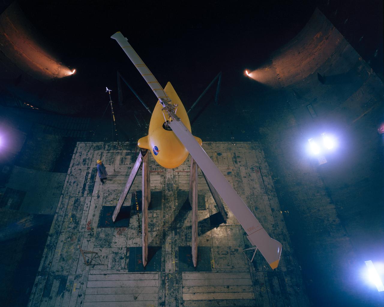
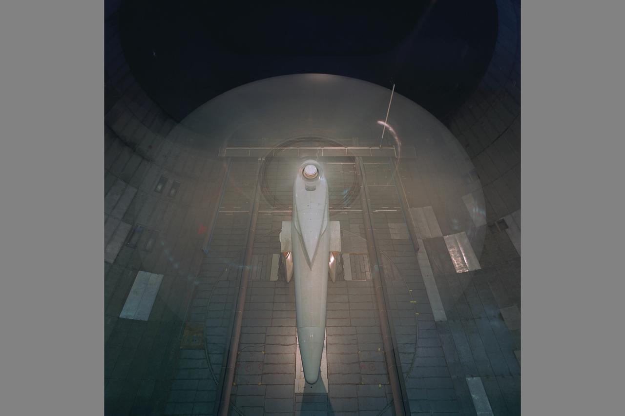
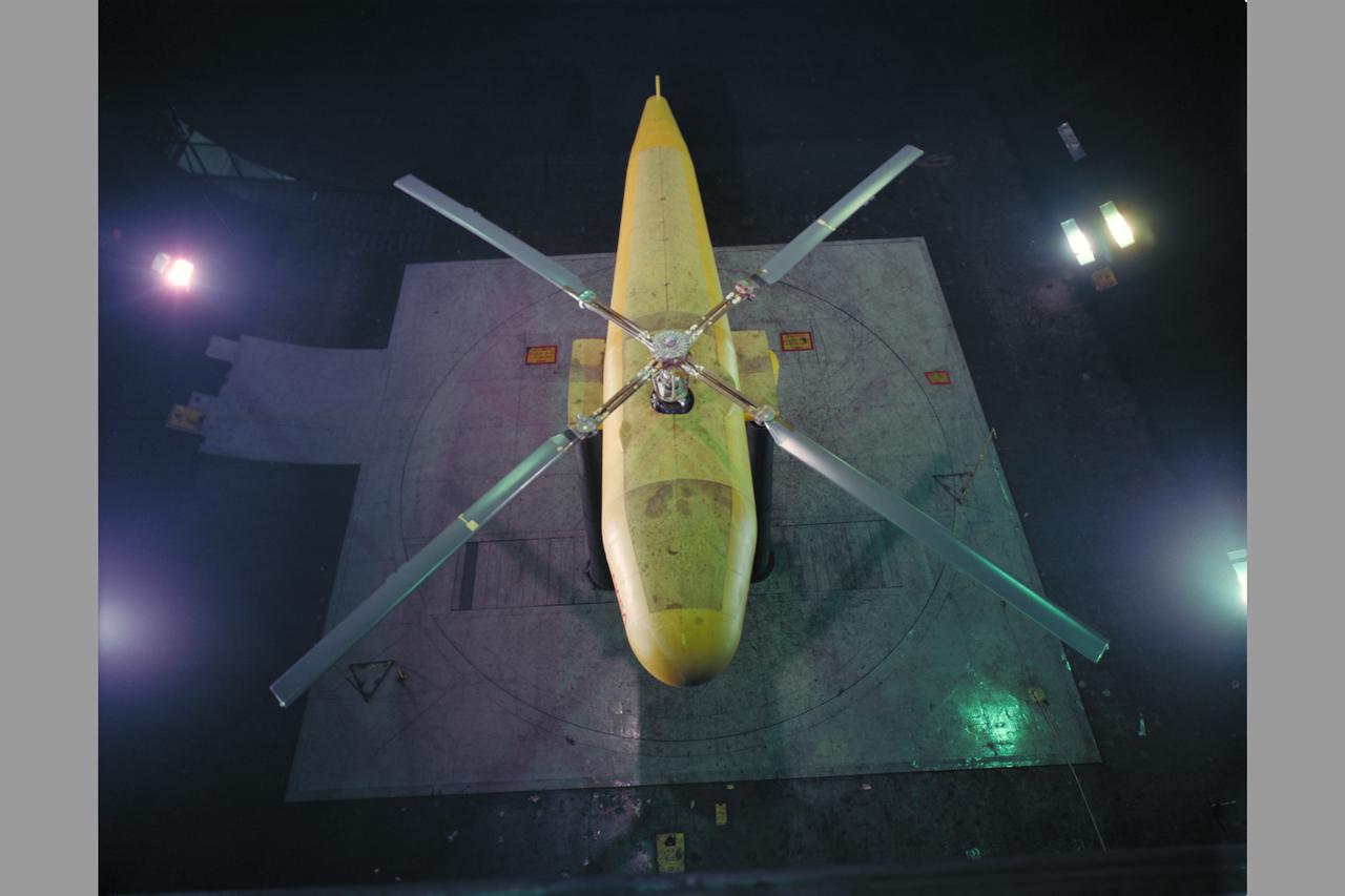
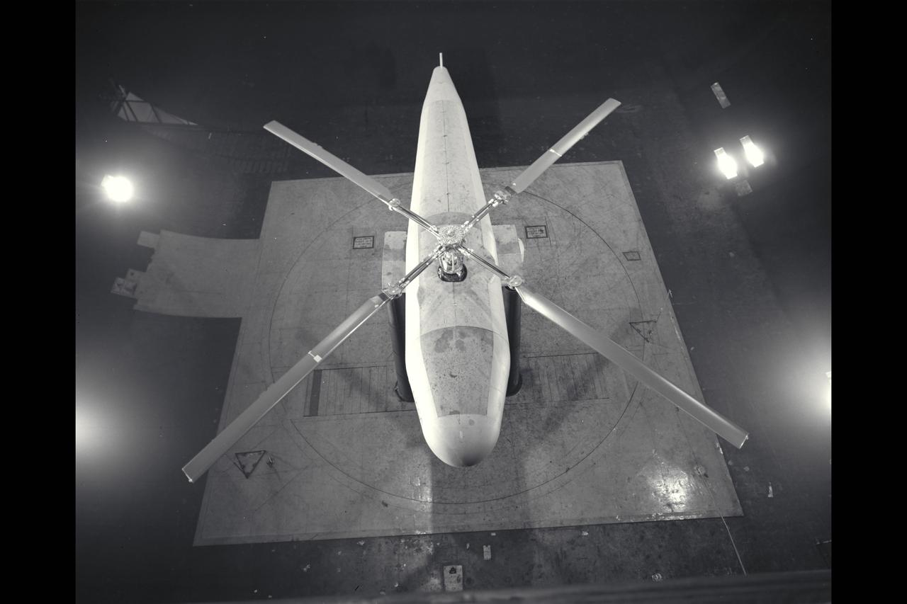
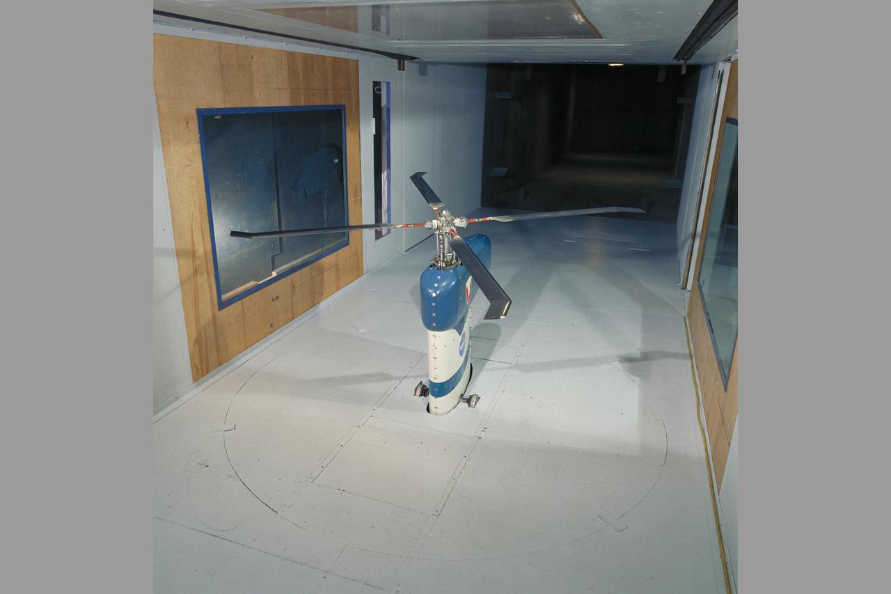
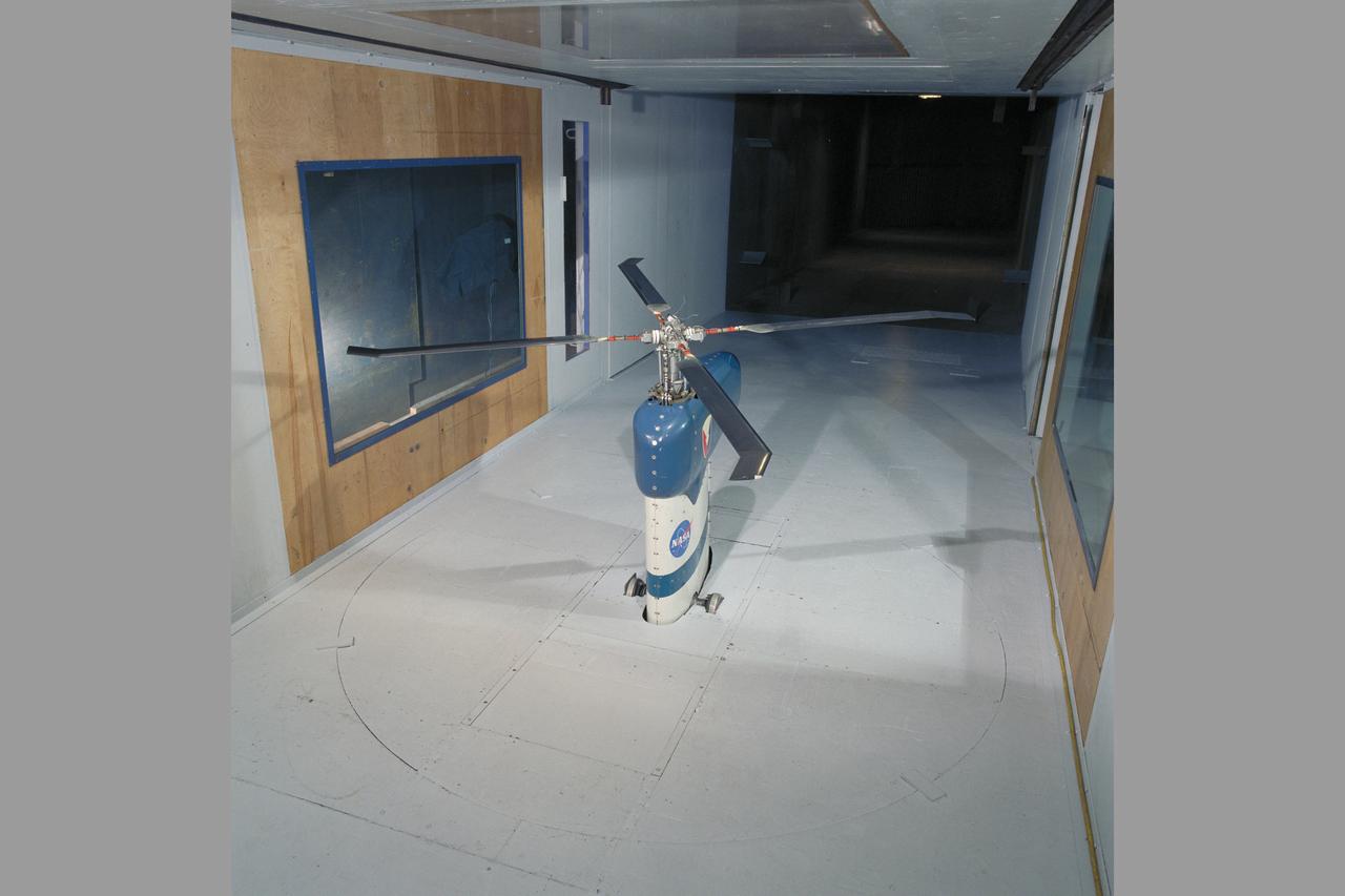
Top Plan view of Bell Rotor with Ed Verrett left frame. Test #437.
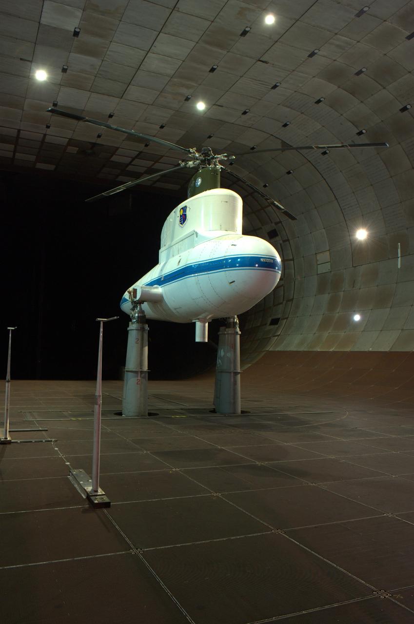
Dutch Netherlands testing of Boeing 360 Vertol Rotor: Full Test

Dutch Netherlands testing of Boeing 360 Vertol Rotor: Full Test
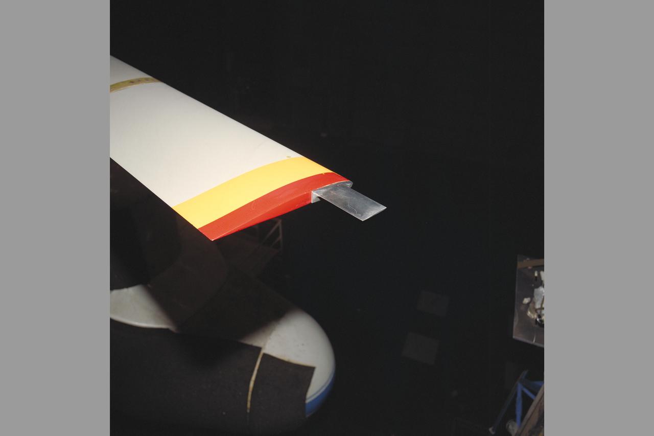
One of the first helicopter tests in the 40 x 80 wind tunnel. John McCloud, pictured, started helicopter work in the 40 x 80. Test 150. Testing the effects of camber on rotor blades.
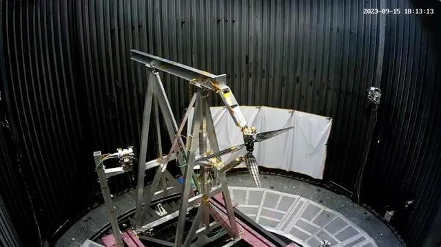
A dual rotor system for the next generation of Mars helicopters is tested in the 25-Foot Space Simulator at NASA's Jet Propulsion Laboratory in Southern California on Sept.15, 2023. Over three weeks, the carbon-fiber blades were spun up at ever-higher speeds and greater pitch angles to see if they would remain intact as their tips approached supersonic speeds. Longer and stronger than those used on NASA's Ingenuity Mars Helicopter, the blades reached Mach 0.95 during the test. The simulator's vacuum chamber allows engineers to test spacecraft and components in conditions like those they would face on Mars. The inset at upper right shows the same test from the perspective of a second camera also located inside the chamber. Movie available at https://photojournal.jpl.nasa.gov/catalog/PIA26079

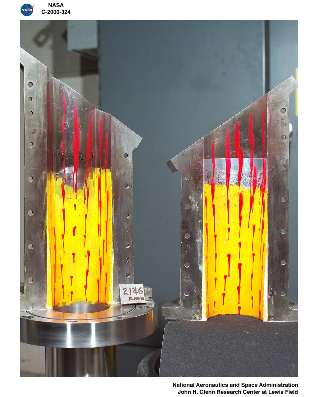
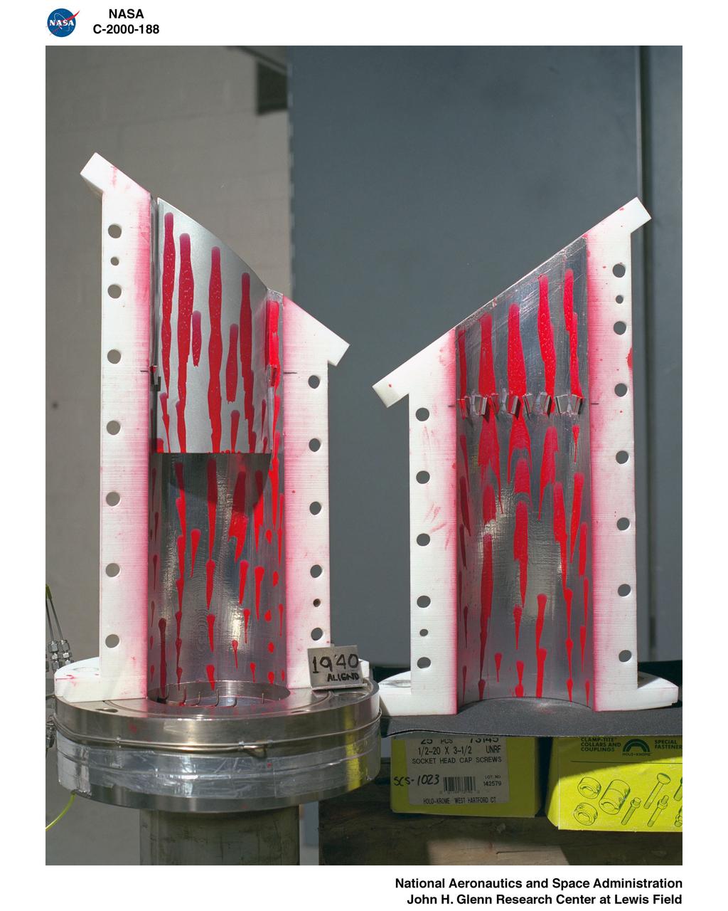
Title: W-8 Fan Acoustic Casing Treatment Test on the Source Diagnostic Test Rotor Alone Hardware Program: Advanced Air Vehicles Program (AAVP) Project: Advanced Air Transport Technology (AATT) Sub-project: Aircraft Noise Reduction (ANR) Weekly Highlight: · Acoustic Casing Treatment Testing Completed in the W-8 Single Stage Axial Compressor Facility: Testing of Acoustic Casing Treatments on the Source Diagnostic Test (SDT) rotor alone hardware which had begun in early January was completed on Thursday, February 16th. Four different over-the-rotor acoustic casing treatment concepts were tested along with two baseline configurations. Testing included steady-aerodynamic measurements of fan performance, hotfilm turbulence measurements, and inlet acoustic measurements with an in-duct array. These measurements will be used to assess the aerodynamic and acoustic impact of fan acoustic casing treatments on a high bypass ratio fan at TRL 3. This test was the last of 3 planned tests of potential over-the-rotor acoustic casing treatments. The first treatment test was completed in the Normal Incidence Tube (NIT) at Langley Research Center (LaRC) in Fall 2015 and the second was completed on the Advanced Noise Control Fan (ANCF) in the Aero-Acoustic Propulsion Laboratory (AAPL) in Winter 2016. This work is supported by the Aircraft Noise Reduction (ANR) subproject of the Advanced Air Transport Technology (AATT) Project. (POC: LTV/ Rick Bozak 3-5160)
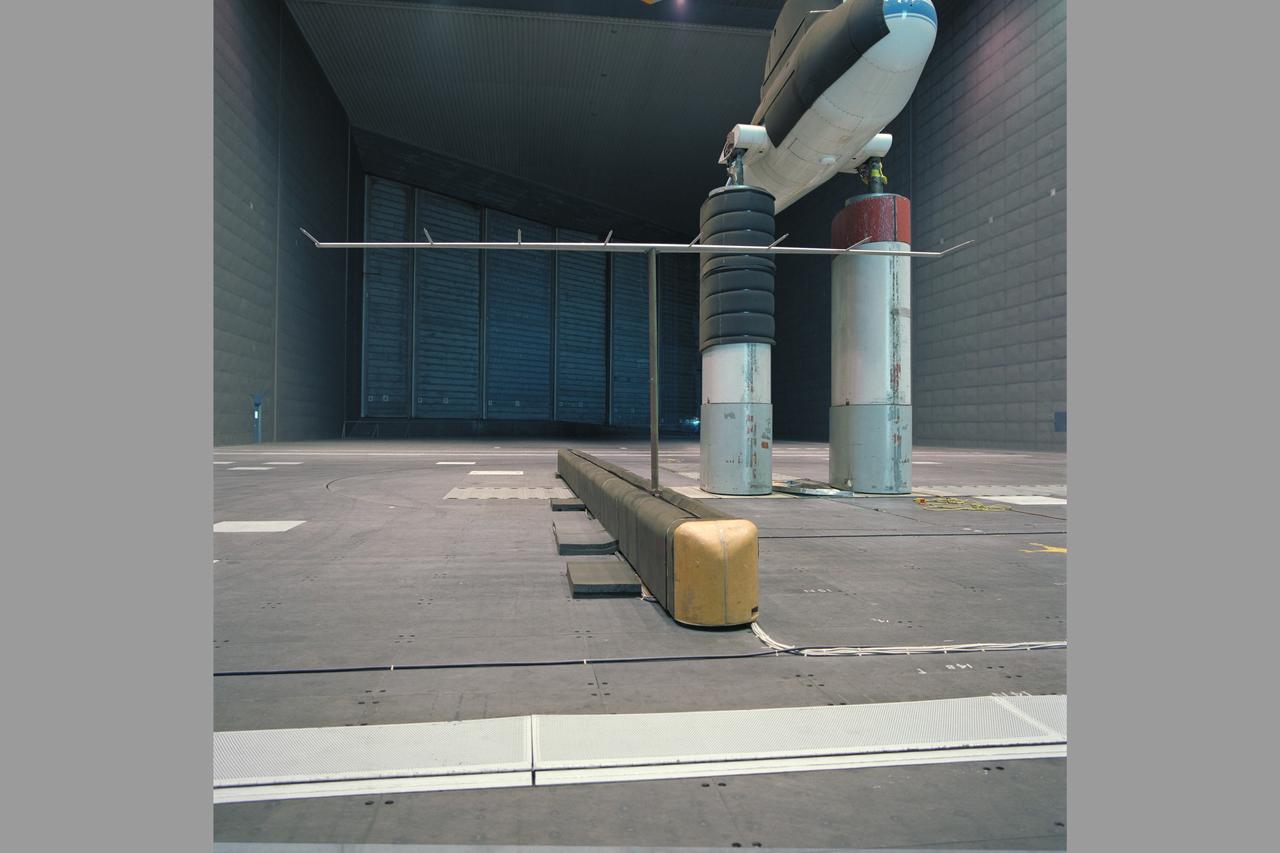
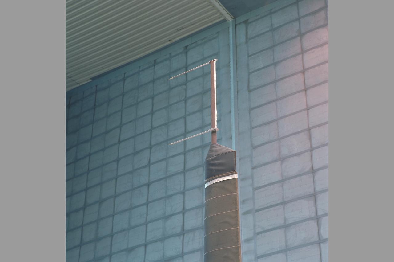
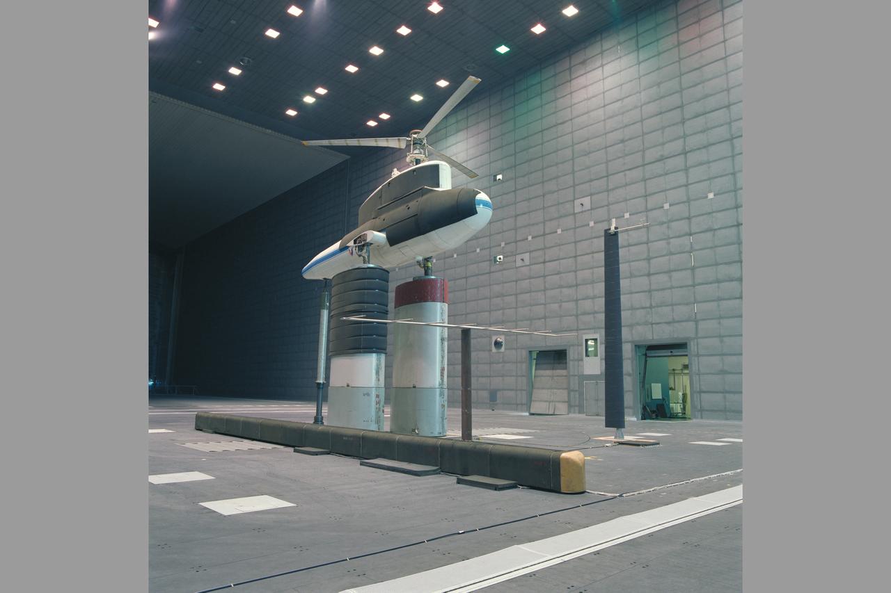
Sikorsky Bearingless Main rotor (SBMR) mounted on the Ames Rotor Test Apparatus (RTA) during testing in the NASA Ames 40x80ft Subsonic Wind Tunnel, test-584. Rotors in motion.
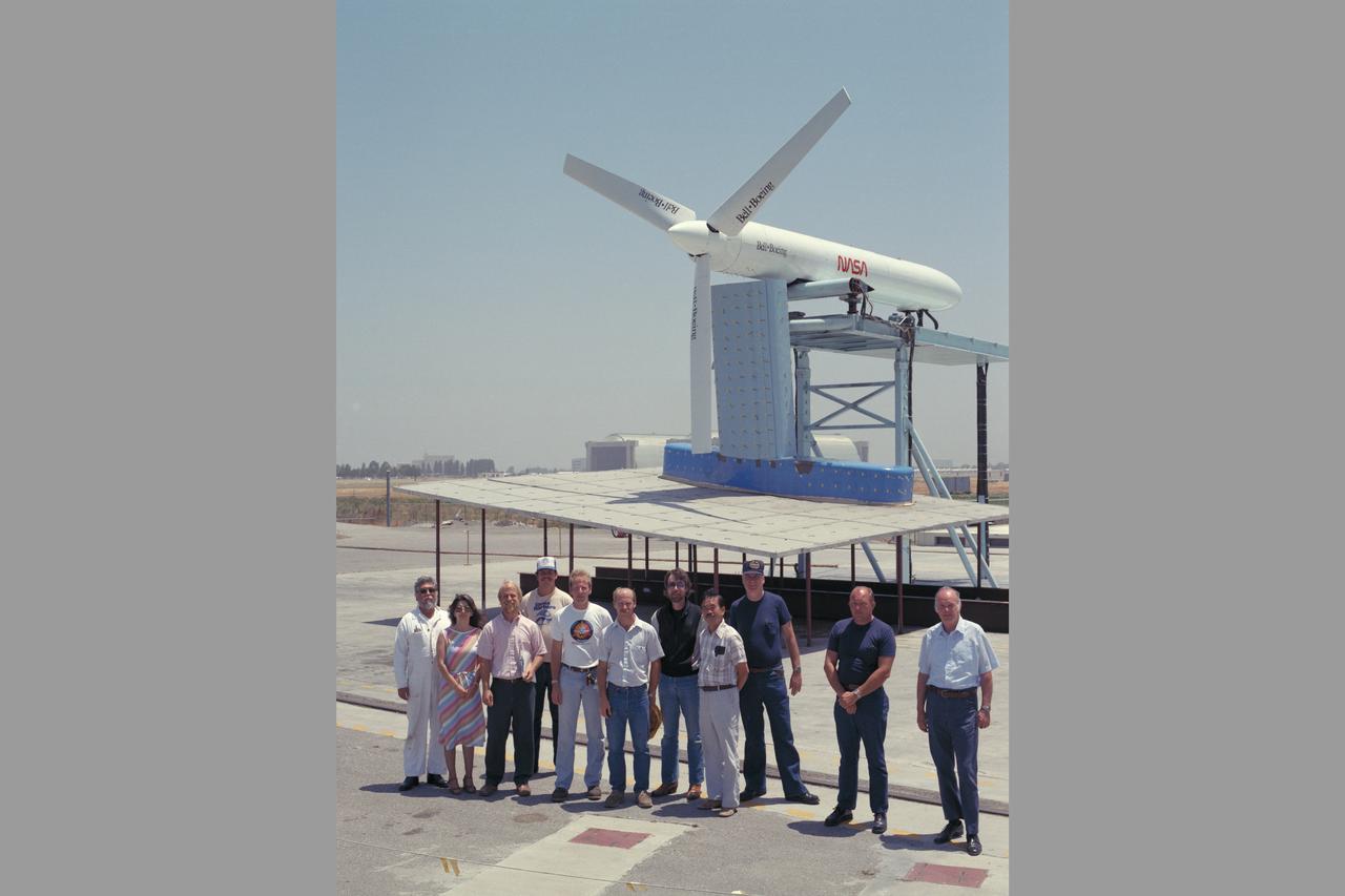
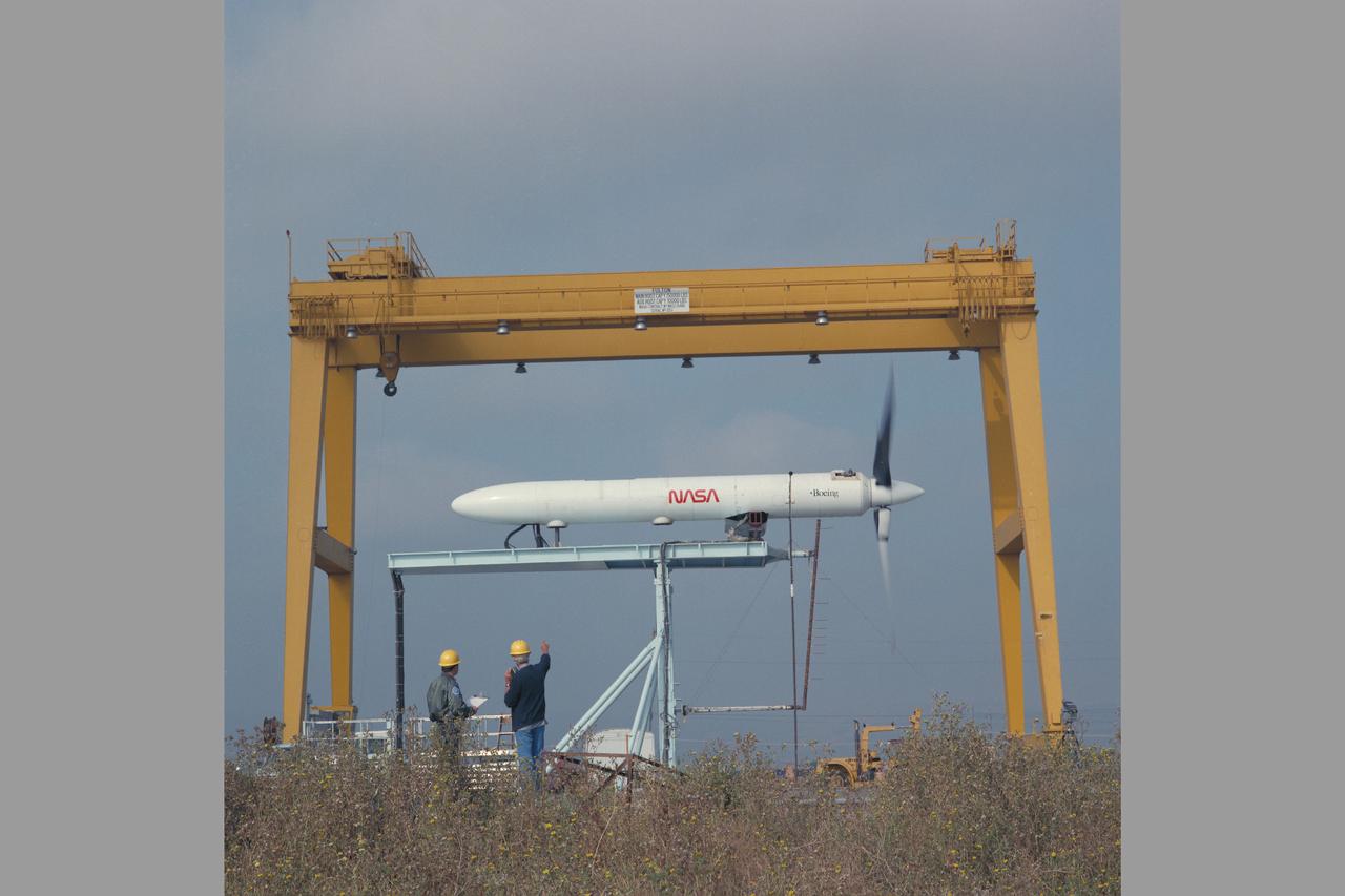
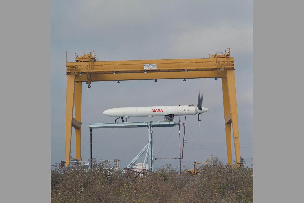
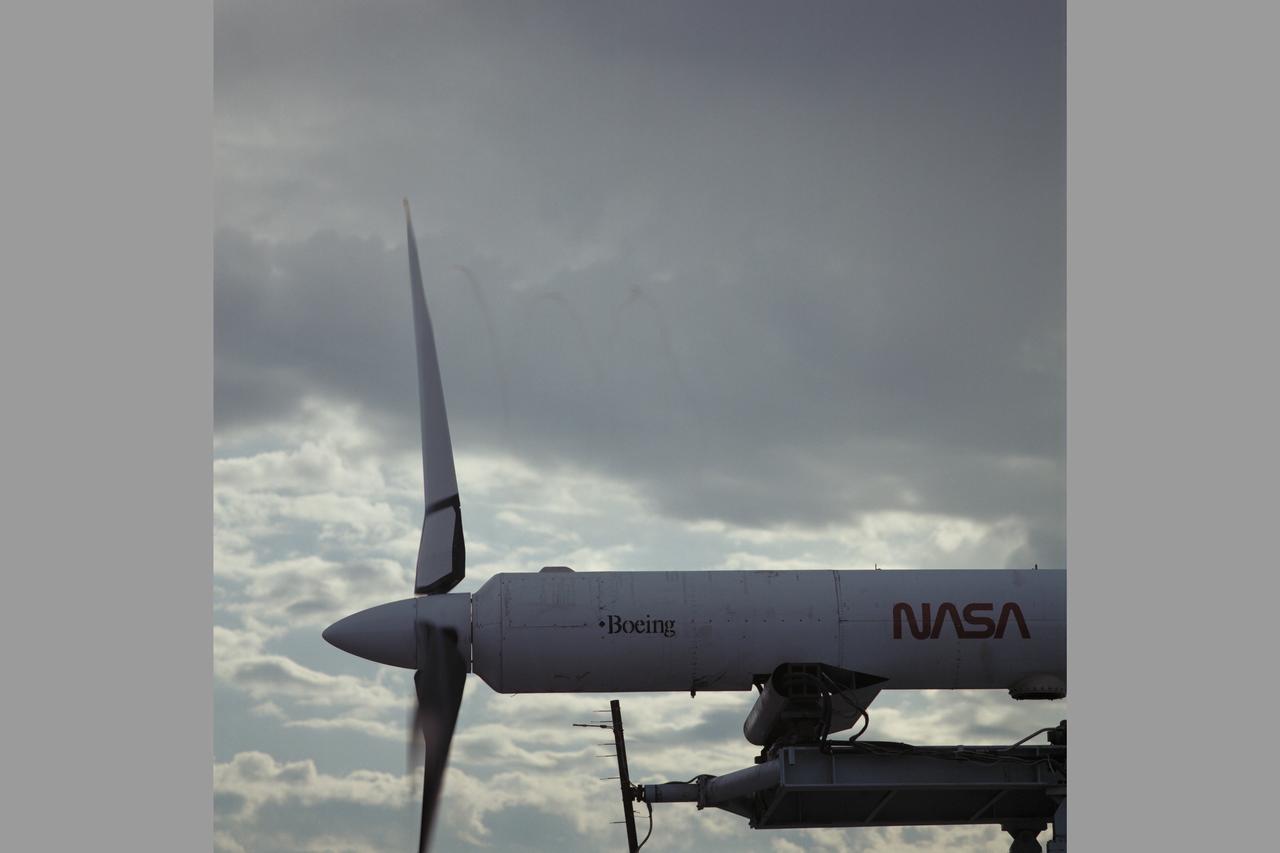
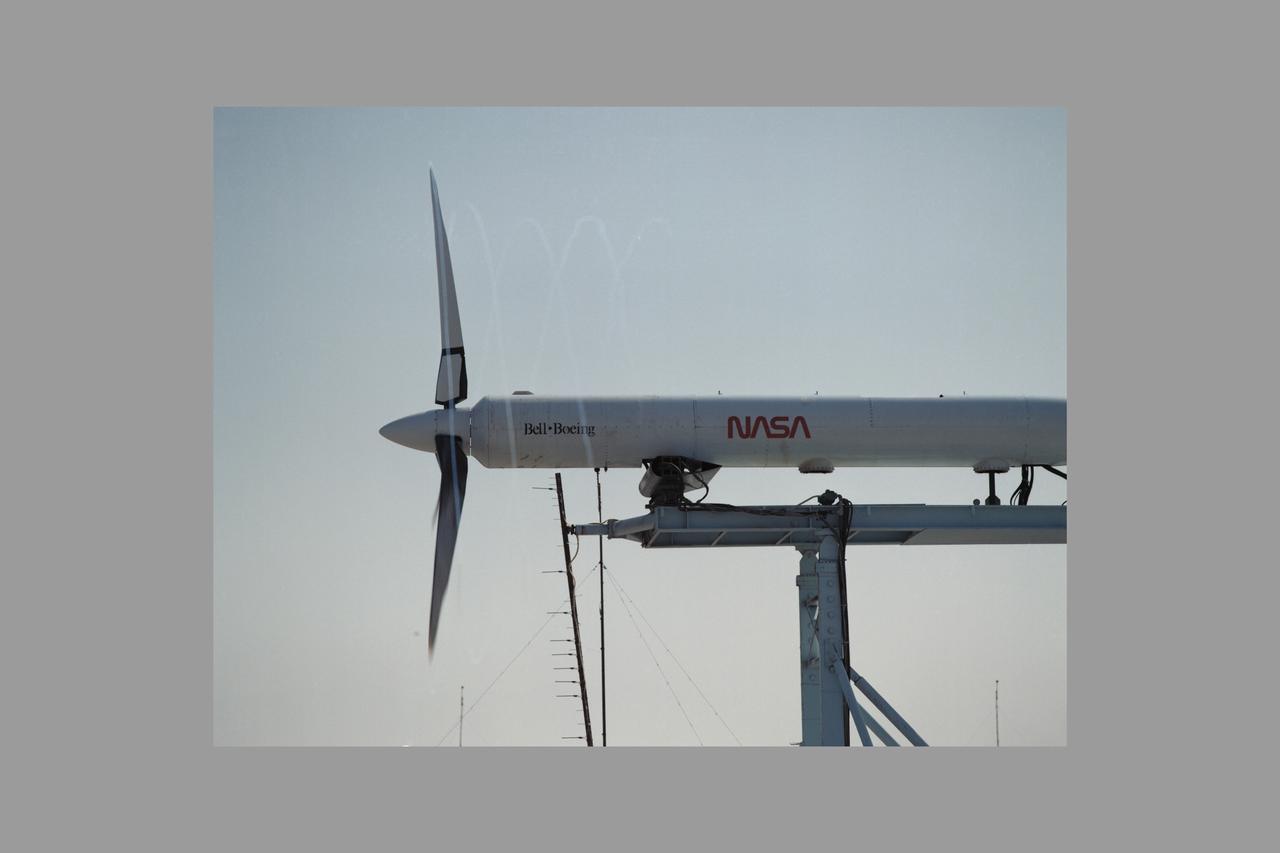
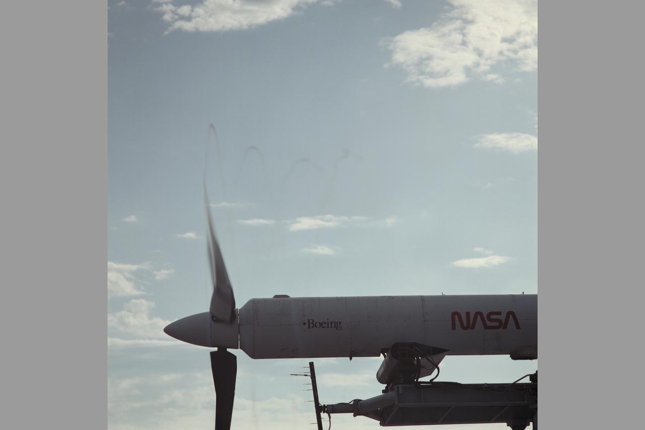
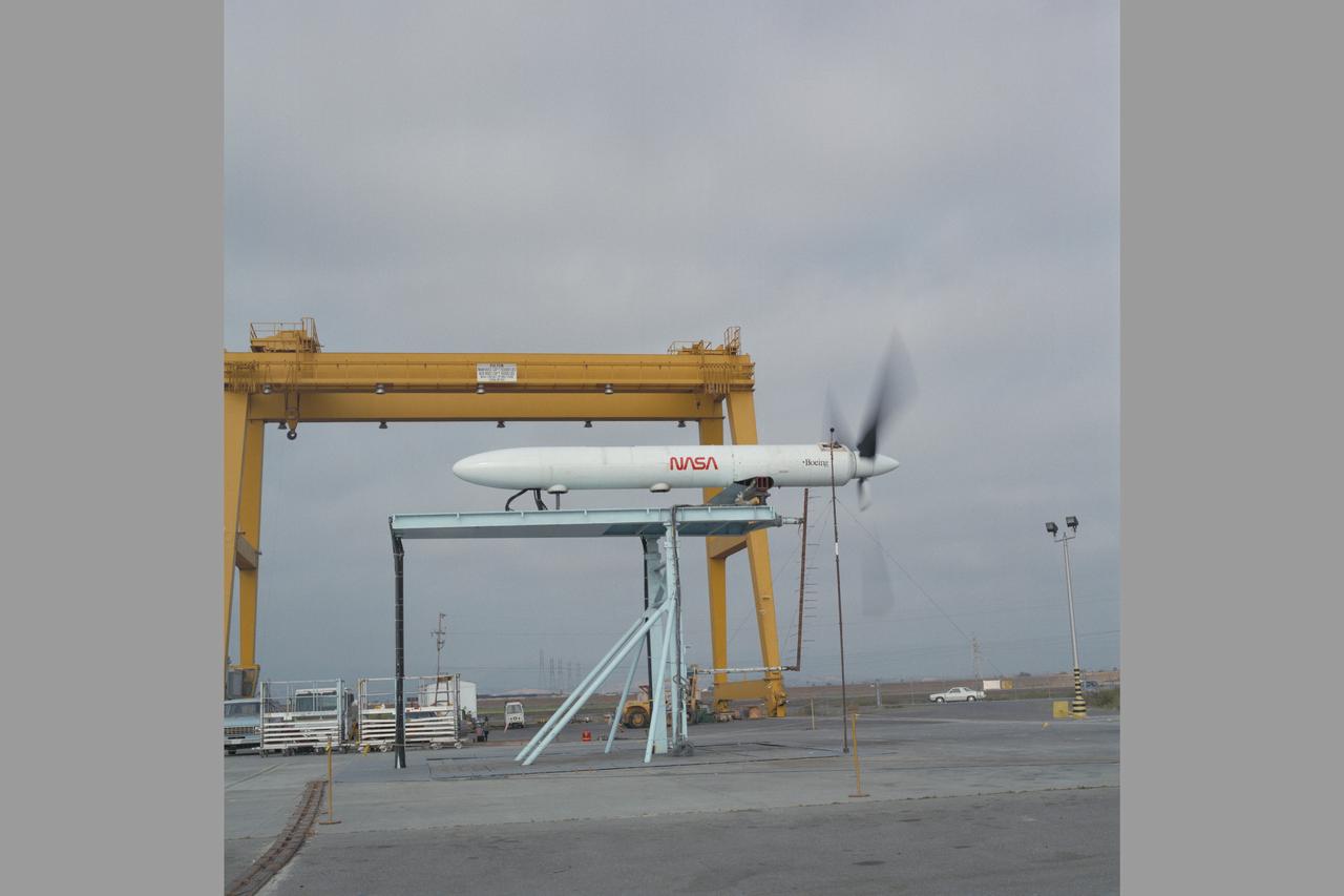
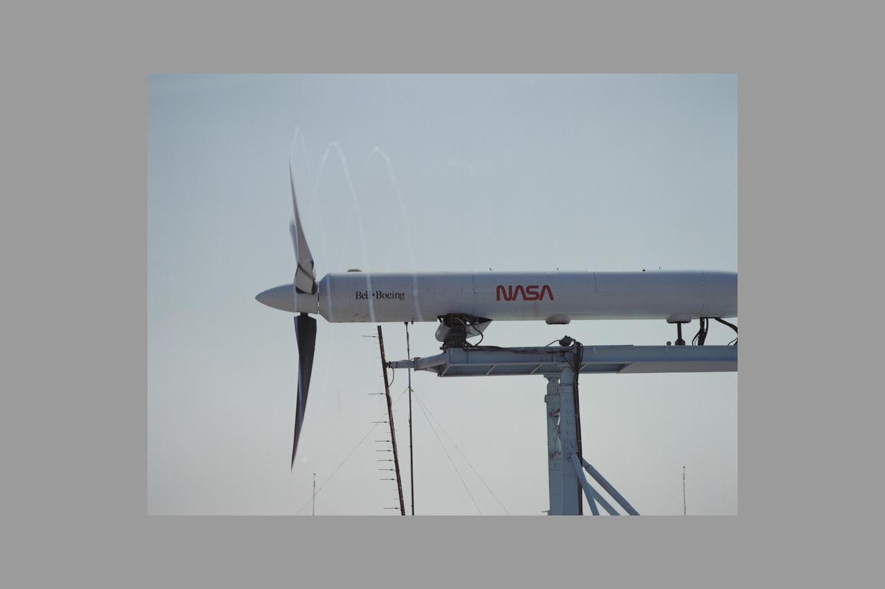
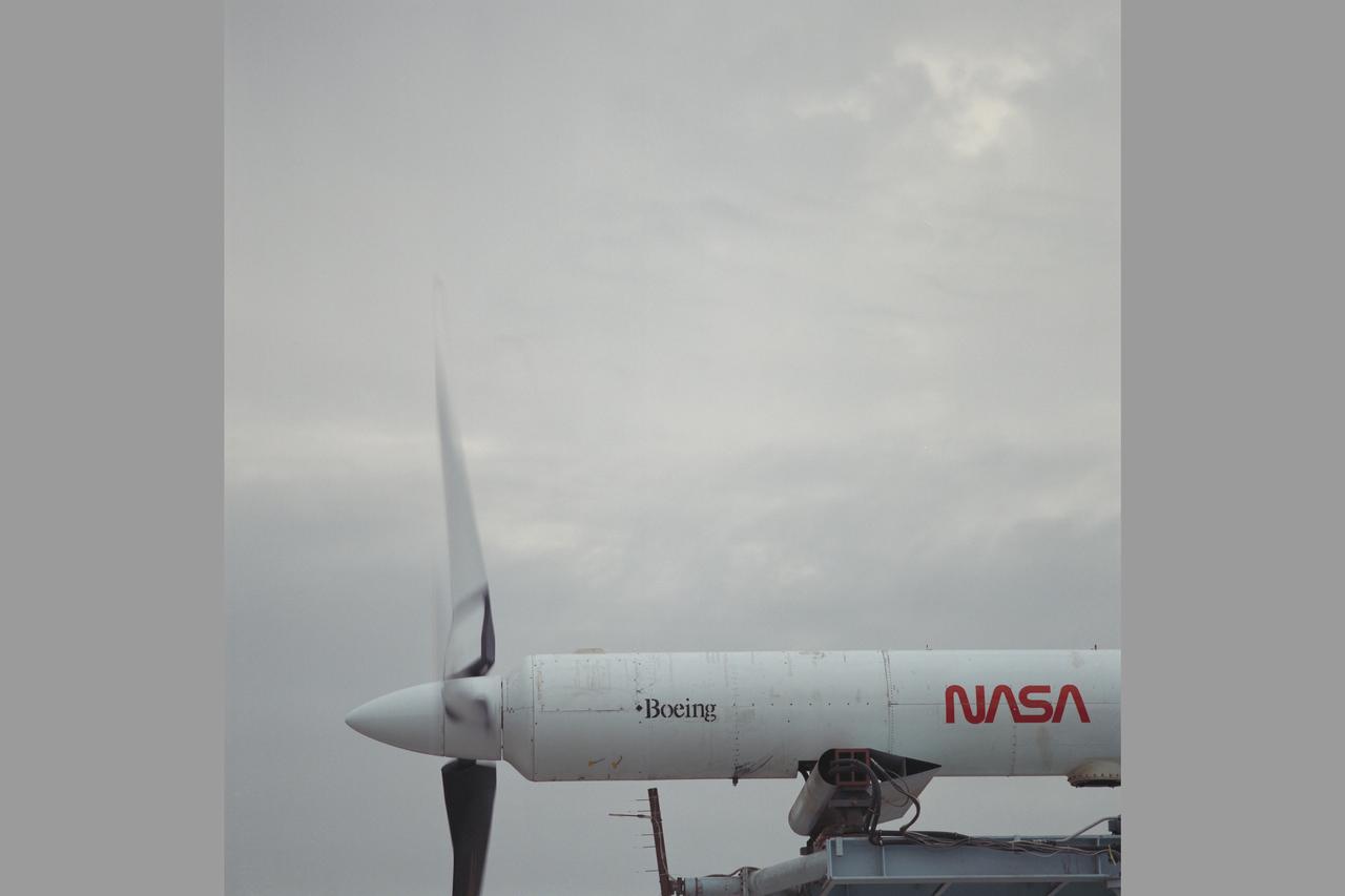
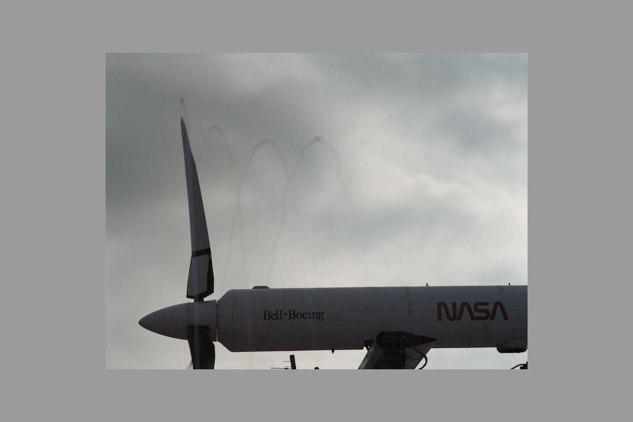
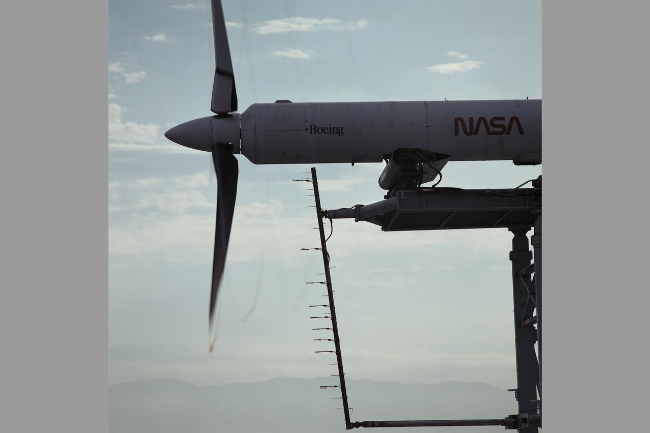
JVX/ATB Rotor Blade Project: Bell Boeing Rotor for the XV-15 tilt rotor Research Aircraft (TRRA) and test crew in front of the OARF
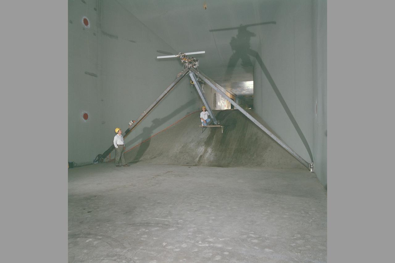
XV-15 Rotor Test Apparatus (RTA) flow visualization Hover test-80-0021 in 80x120ft w.t. (rotor tip)
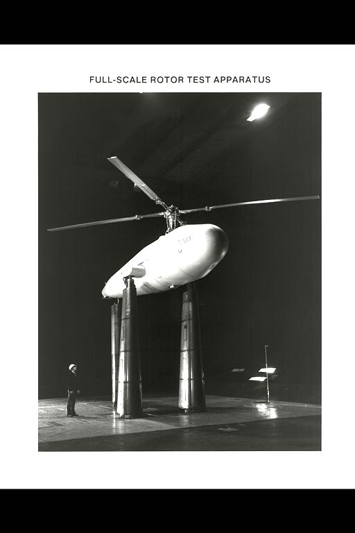
Sykorsky Bearingless Main Rotor test in 40x80ft w.t. (Full-Scale Rotor Test Apparatus)
Sikorsky Bearingless Main rotor (SBMR) mounted on the Ames Rotor Test Apparatus (RTA) for testing in the NASA Ames40x80ft Subsonic Wind Tunnel, test-584.
Sikorsky Bearingless Main rotor (SBMR) mounted on the Ames Rotor Test Apparatus (RTA) for testing in the NASA Ames40x80ft Subsonic Wind Tunnel, test-584.
Sikorsky Bearingless Main rotor (SBMR) mounted on the Ames Rotor Test Apparatus (RTA) for testing in the NASA Ames40x80ft Subsonic Wind Tunnel, test-584.
Sikorsky Bearingless Main rotor (SBMR) mounted on the Ames Rotor Test Apparatus (RTA) for testing in the NASA Ames40x80ft Subsonic Wind Tunnel, test-584.
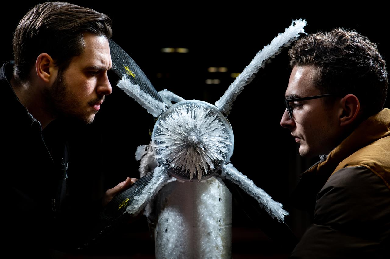
Curtis Flack (left) and Paul von Hardenberg (right) inspect the ice formation on the spinner of an Advanced Air Mobility proprotor model tested in the Icing Research Tunnel. The data from the test will be used by icing researchers to better understand the risks of icing on electric vertical takeoff and landing vehicles which will assist with the design and certification of new aircraft.
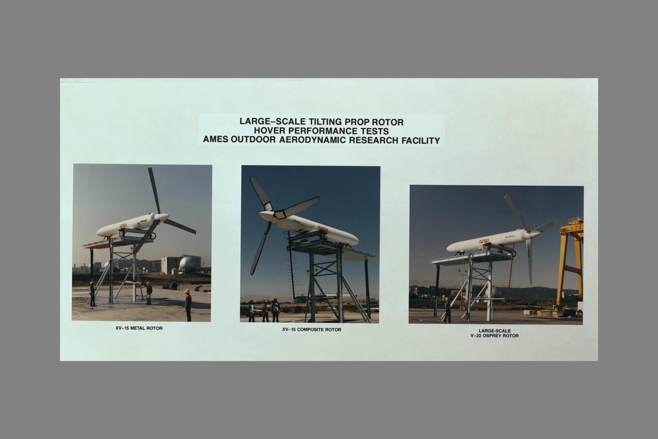
NASA Ames Graphics of LARGE-SCALE TILTING PROP ROTOR HOVER PERFORMANCE TESTS AMES OARF COMPOSITE. (ref: XV-15 Metal Rotor AC84-0176-13, XV-15 Composite Rotor from AC84-0498 series, V-22 Osprey AC84-0059-11 testing at OARF)
Sikorsky Bearingless Main rotor (SBMR) mounted on the Ames Rotor Test Apparatus (RTA) for testing in the NASA Ames 40x80ft Subsonic Wind Tunnel, test-584. Shown with NASA engineer Bob McMahon
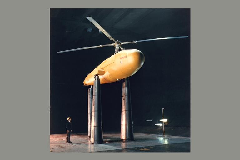
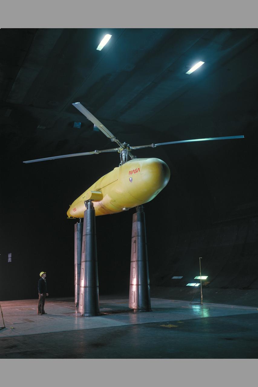
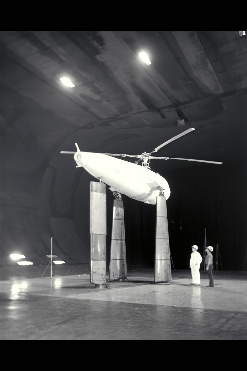
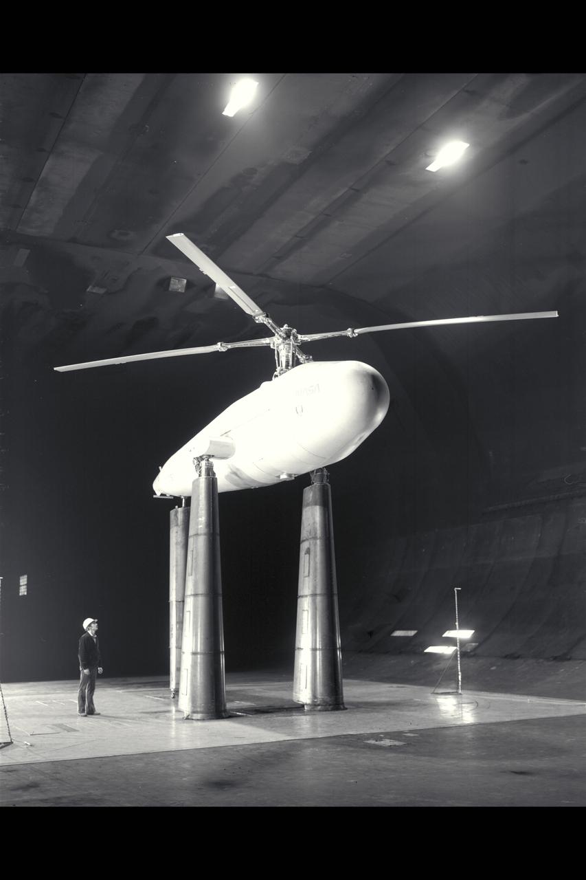
3/4 front view of model in Ames 40x80 foot wind tunnel.
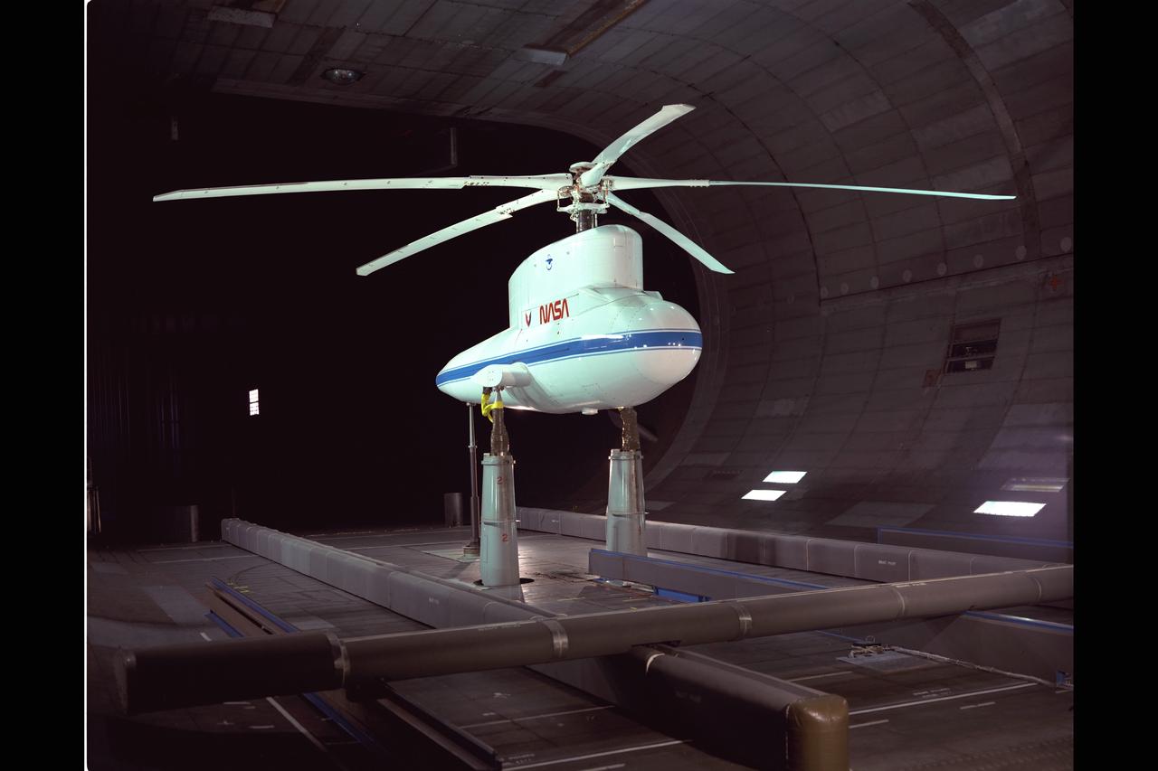
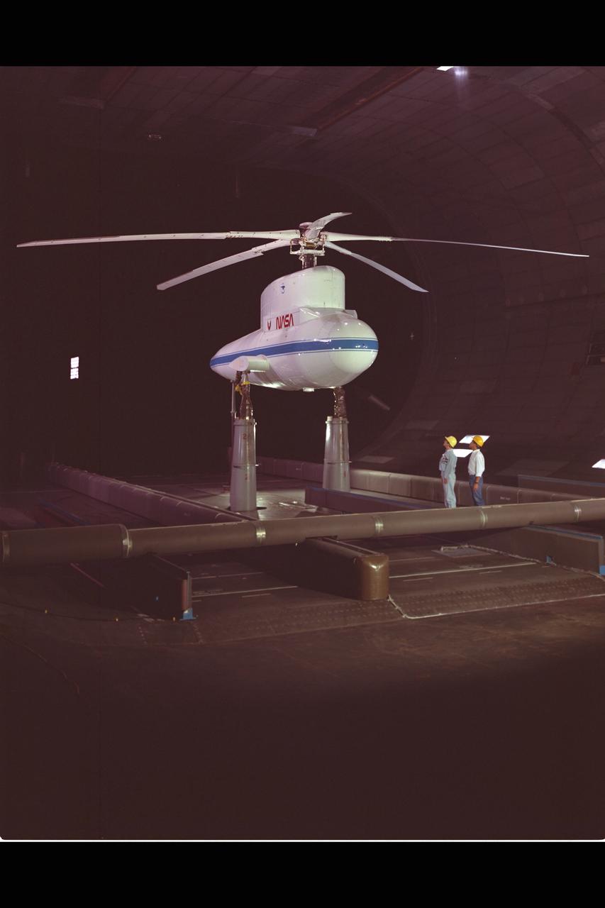
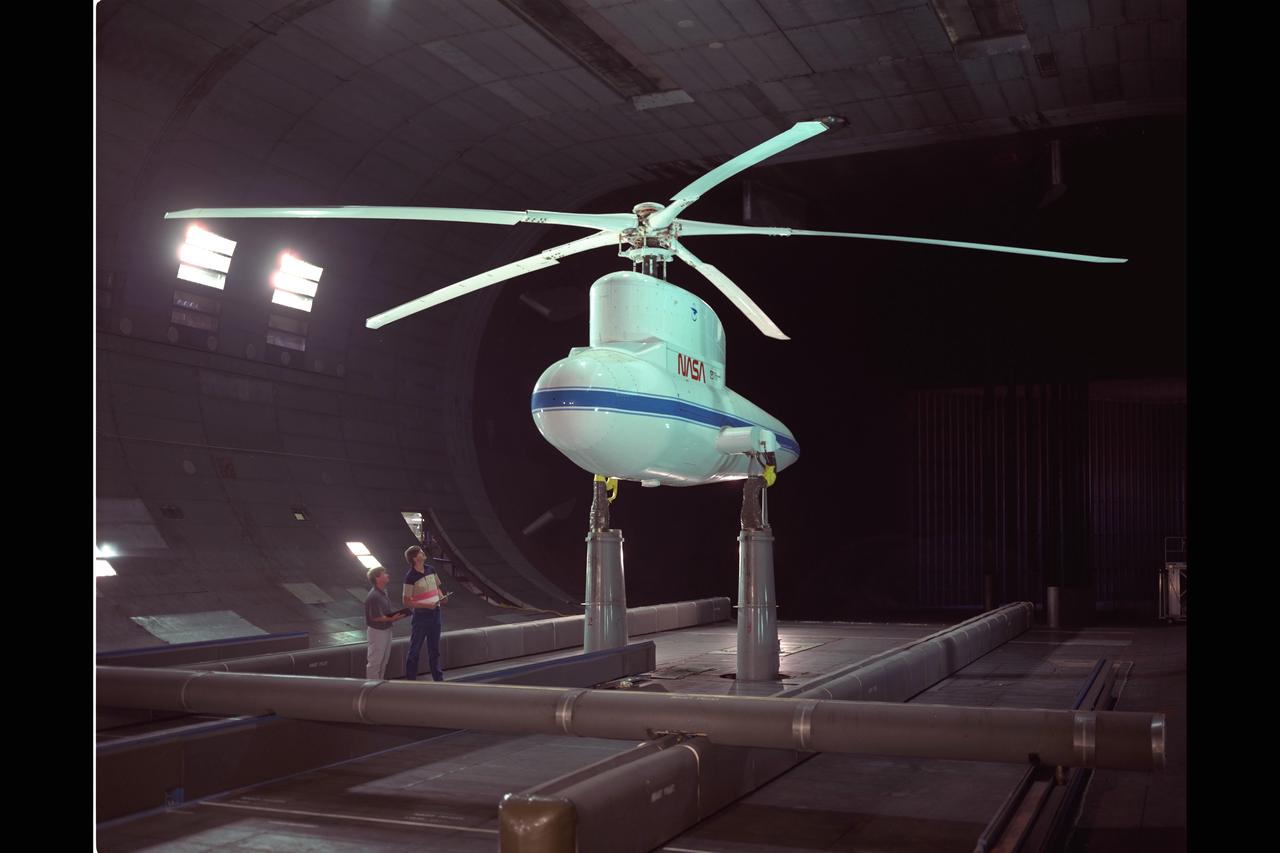
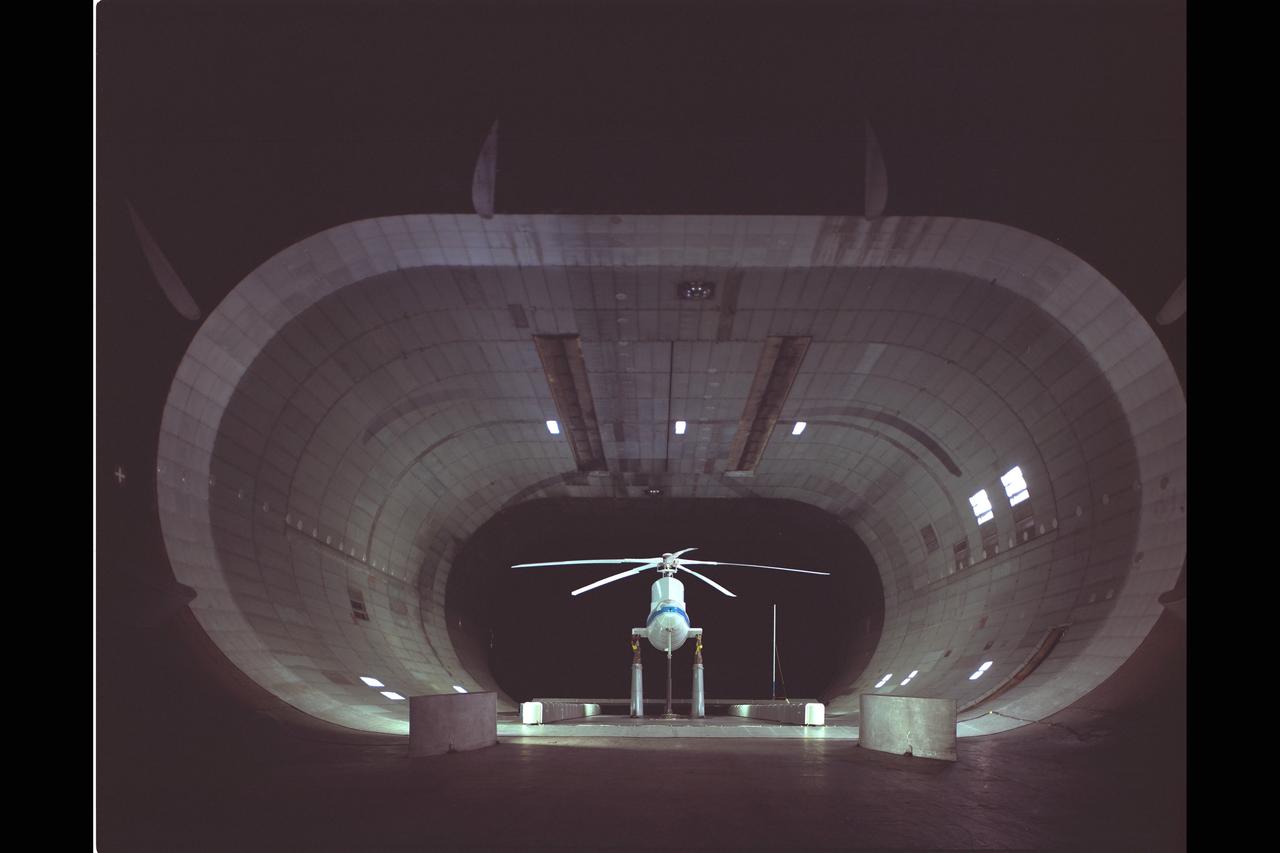
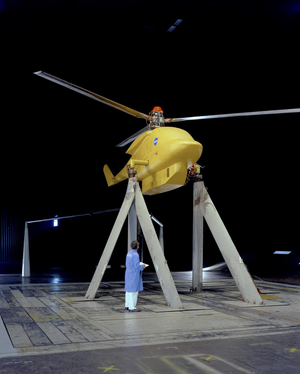
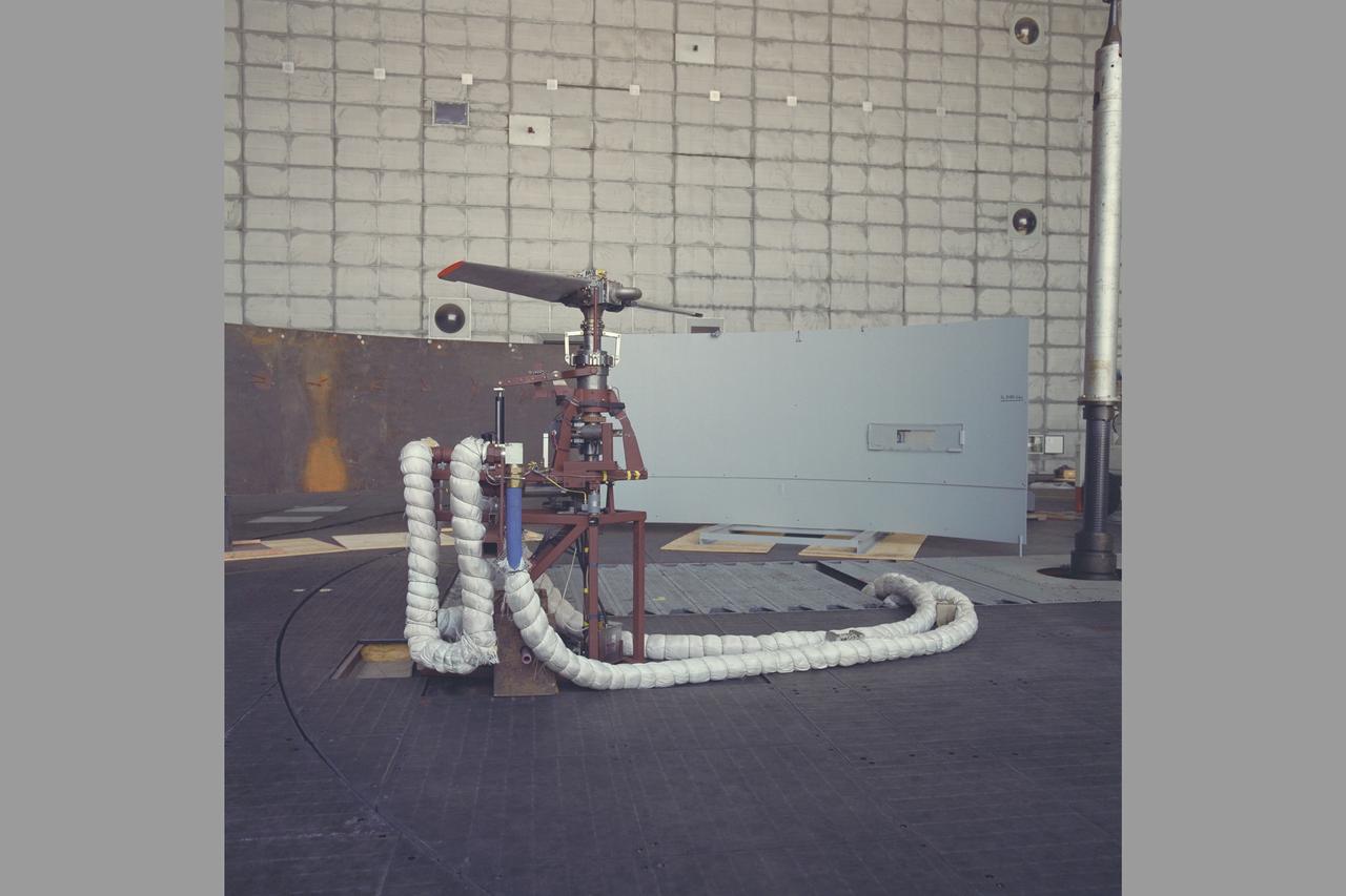
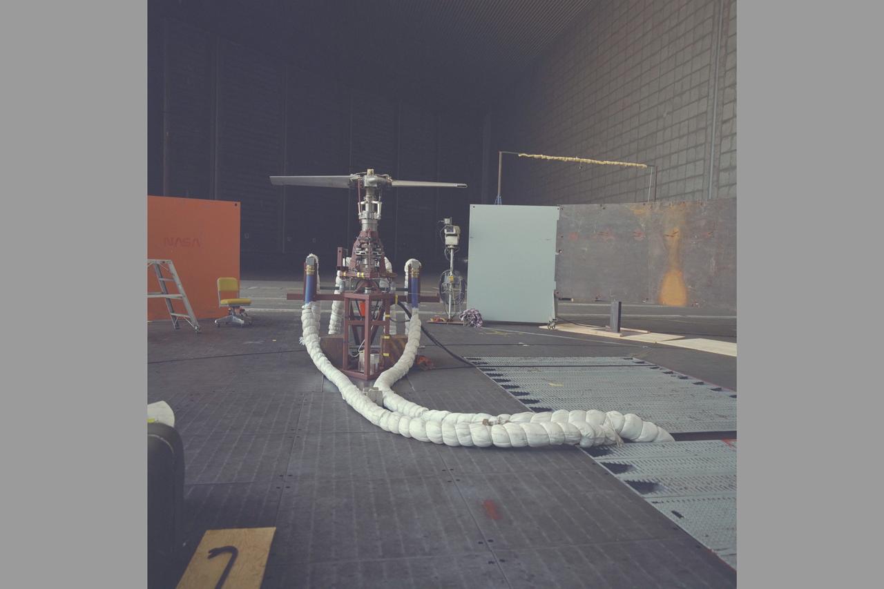
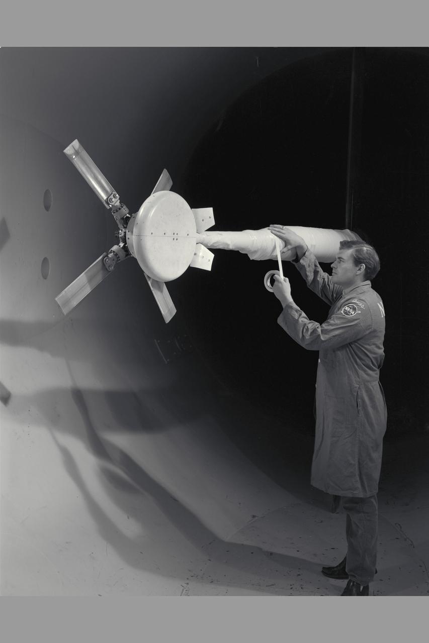
LEVITATED DUCTED FAN TEST ROTOR
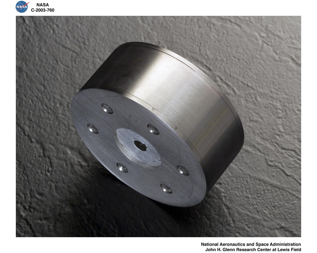
LEVITATED DUCTED FAN TEST ROTOR
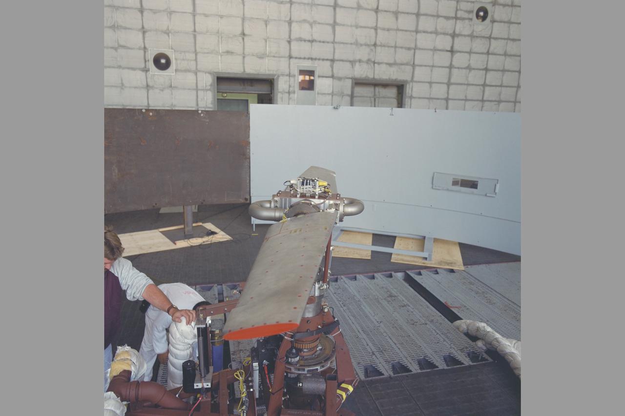
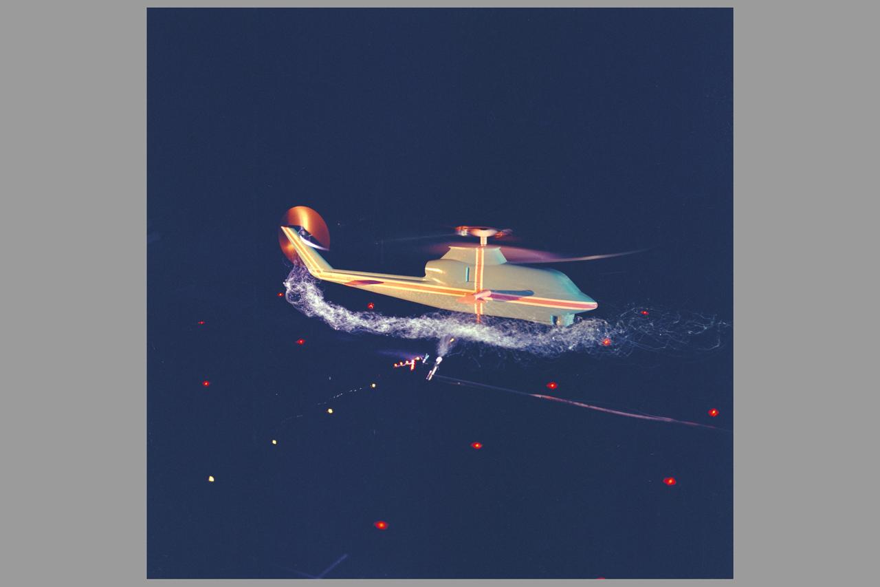
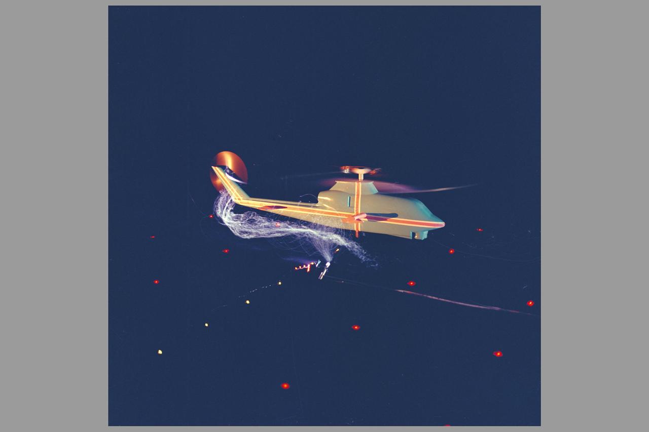
Canard Rotor test 80x120ft. w.t test-80-0024
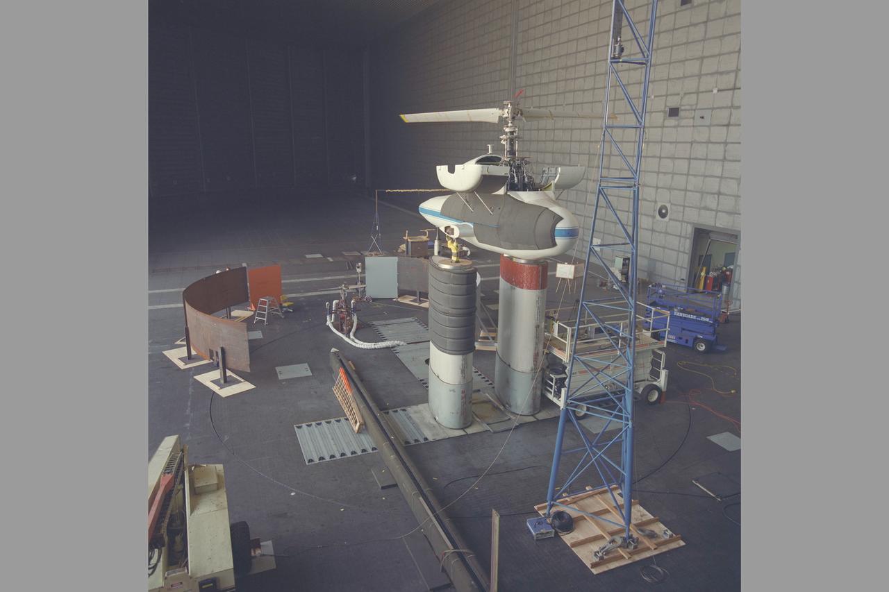
Canard Rotor test 80x120ft. w.t test-80-0024
Canard Rotor test 80x120ft. w.t test-80-0024
Canard Rotor test 80x120ft. w.t test-80-0024
Sikorsky Bearingless Main Rotor test in 40x80ft w.t.
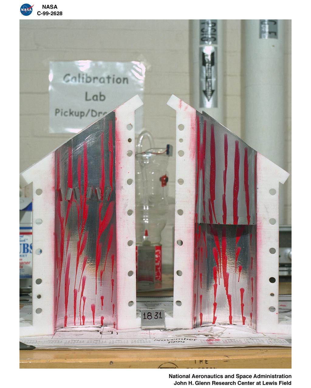
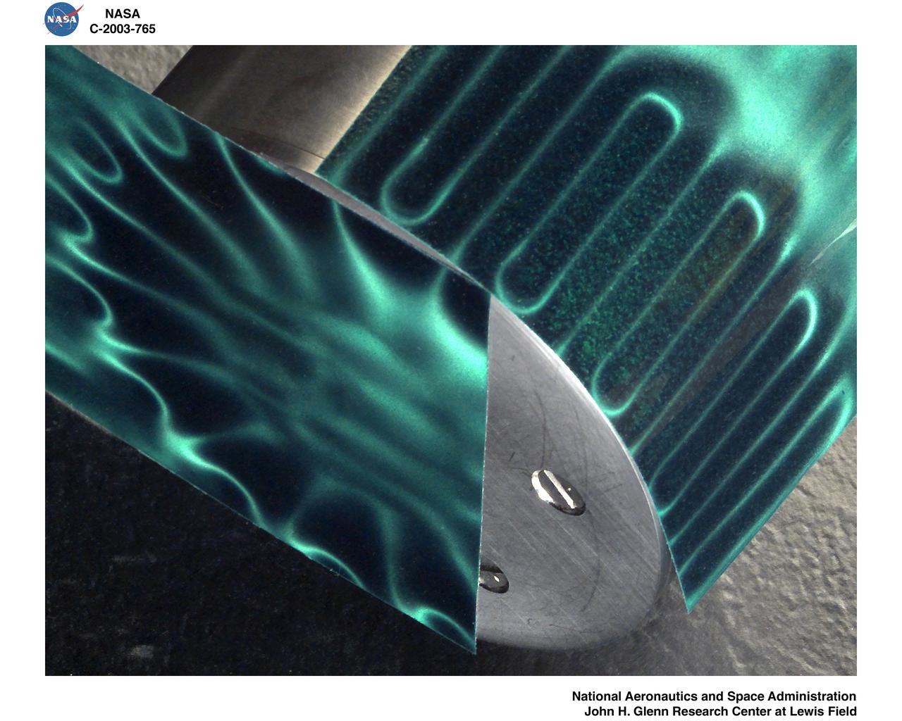
VORTEX GENERATOR TEST FOR WAVE ROTOR APPLICATIONS
Sikorsky Bearingless Main Rotor test in 40x80ft w.t.
Sikorsky Bearingless Main Rotor test in 40x80ft w.t.
VORTEX GENERATOR TEST FOR WAVE ROTOR APPLICATIONS
SYKORSKY BEARINGLESS MAIN ROTOR TEST IN 40X80FT W.T.
Sykorsky Bearingless Main Rotor test in 40x80ft w.t.
VORTEX GENERATOR TEST FOR WAVE ROTOR APPLICATIONS
Sykorsky Bearingless Main Rotor test in 40x80ft w.t.
Assent Test (Rotor) 7x10ft#1 W.T.
3/4 lower rear view of Controllable Twist Rotor (CTR) test of 4 blade helicopter model. Pictures with Ben Mandwyler Andy Lemnios, in 40x80 foot wind tunnel. Small flaps on rotor blades.
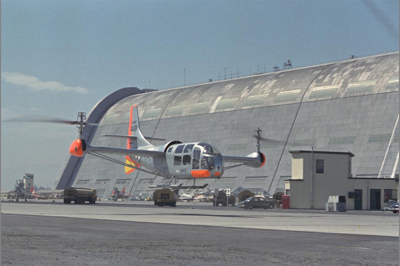
XV-3 HOVERING ON RAMP. Flight Test of Bell XV-3 Convertiplane. Bell VTOL tilt-rotor aircraft hovering along side Hangar One at Moffett Field. The XV-3 design combined a helicopter rotor and a wing. A 450 horsepower Pratt & Whitney piston engine drove the two rotors. The XV-3, first flown in 1955 , was the first tilt-rotor to achieve 100% tilting of rotors. The vehicle was underpowered, however, and could not hover out of ground effect. Note the large ventral fin, which was added to imrpove directional stability in cruse (Oct 1962)
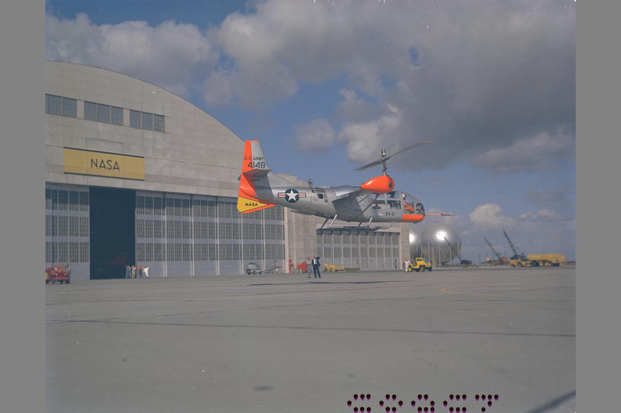
XV-3 HOVERING ON RAMP. Flight Test of Bell XV-3 Convertiplane. Bell VTOL tilt-rotor aircraft hovering in front of building N-211 at Moffett Field. The XV-3 design combined a helicopter rotor and a wing. A 450 horsepower Pratt & Whitney piston engine drove the two rotors. The XV-3, first flown in 1955 , was the first tilt-rotor to achieve 100% tilting of rotors. The vehicle was underpowered, however, and could not hover out of ground effect. Note the large ventral fin, which was added to imrpove directional stability in cruse (Oct 1962)
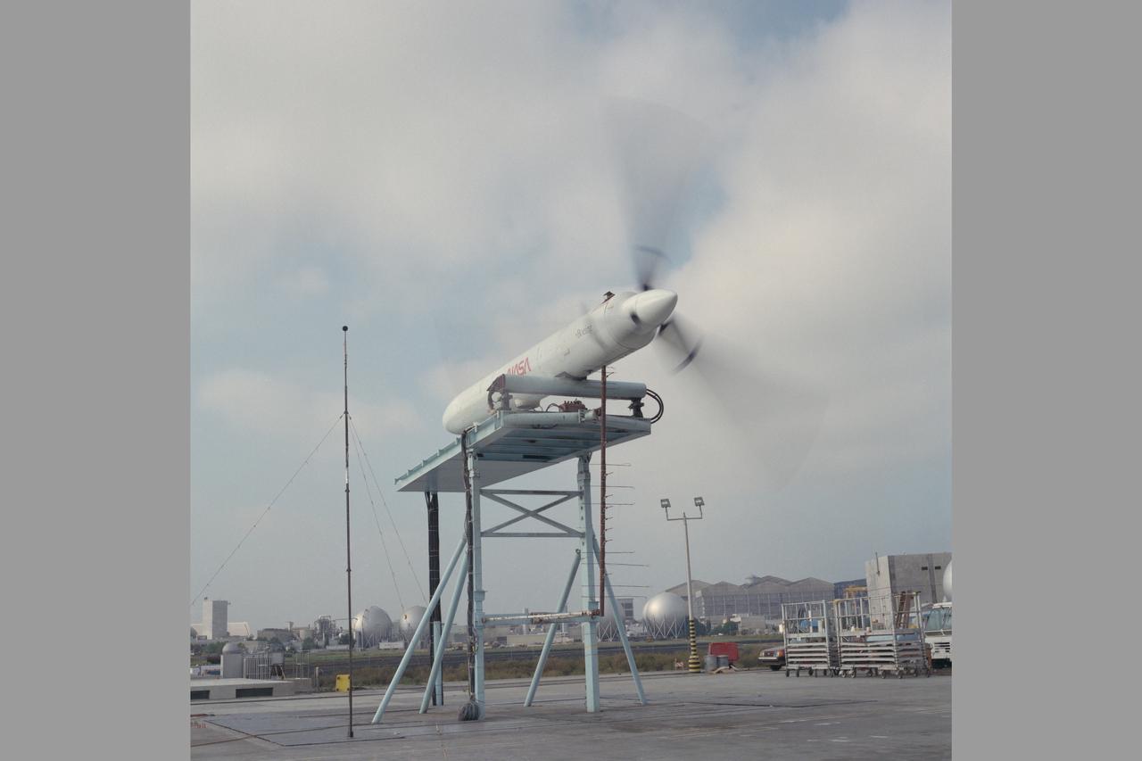
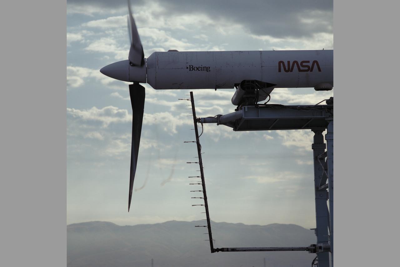
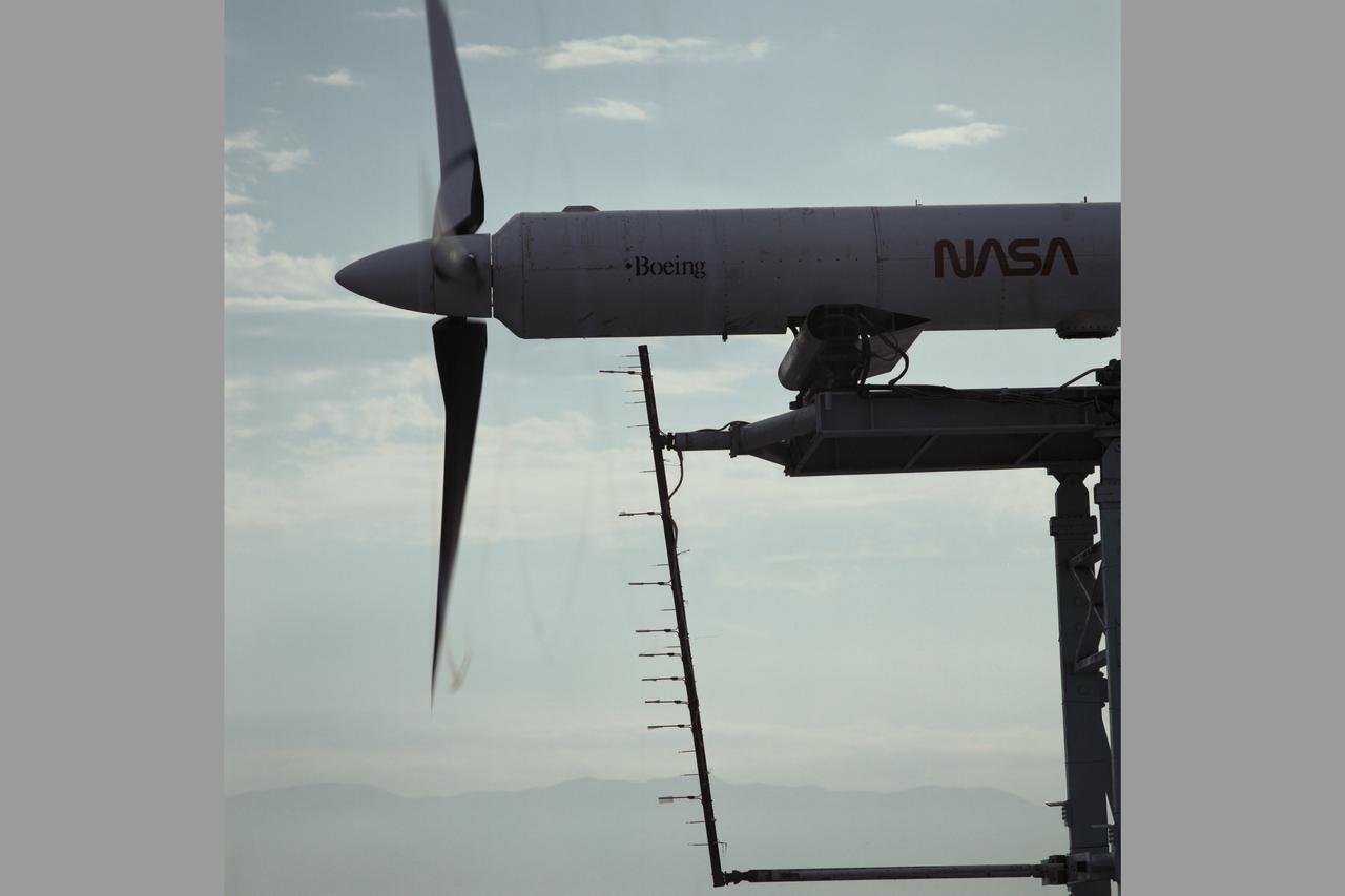
JVX/ATB Rotor Blades Test; OARF Static Test Stand N-249.
JVX/ATB Rotor Blades Test; OARF Static Test Stand N-249.
JVX/ATB Rotor Blades Test; OARF Static Test Stand N-249.
JVX/ATB Rotor Blades Test; OARF Static Test Stand N-249.
JVX/ATB Rotor Blades Test; OARF Static Test Stand N-249.
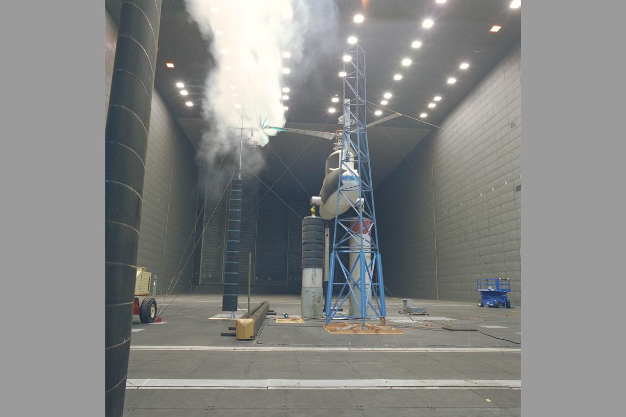
XV-15 Rotor Test Apparatus (RTA) flow visualization Hover test-80-0021 in 80x120ft w.t.
JVX/ATB Rotor Blades Test; OARF Static Test Stand N-249.

JVX/ATB Rotor Blades Test; OARF Static Test Stand N-249.
JVX/ATB Rotor Blades Test; OARF Static Test Stand N-249.
JVX/ATB Rotor Blades Test; OARF Static Test Stand N-249.
JVX/ATB Rotor Blades Test; OARF Static Test Stand N-249.
JVX/ATB Rotor Blades Test; OARF Static Test Stand N-249.
JVX/ATB Rotor Blades Test; OARF Static Test Stand N-249.
JVX/ATB Rotor Blades Test; OARF Static Test Stand N-249.
JVX/ATB Rotor Blades Test; OARF Static Test Stand N-249.
JVX/ATB Rotor Blades Test; OARF Static Test Stand N-249.
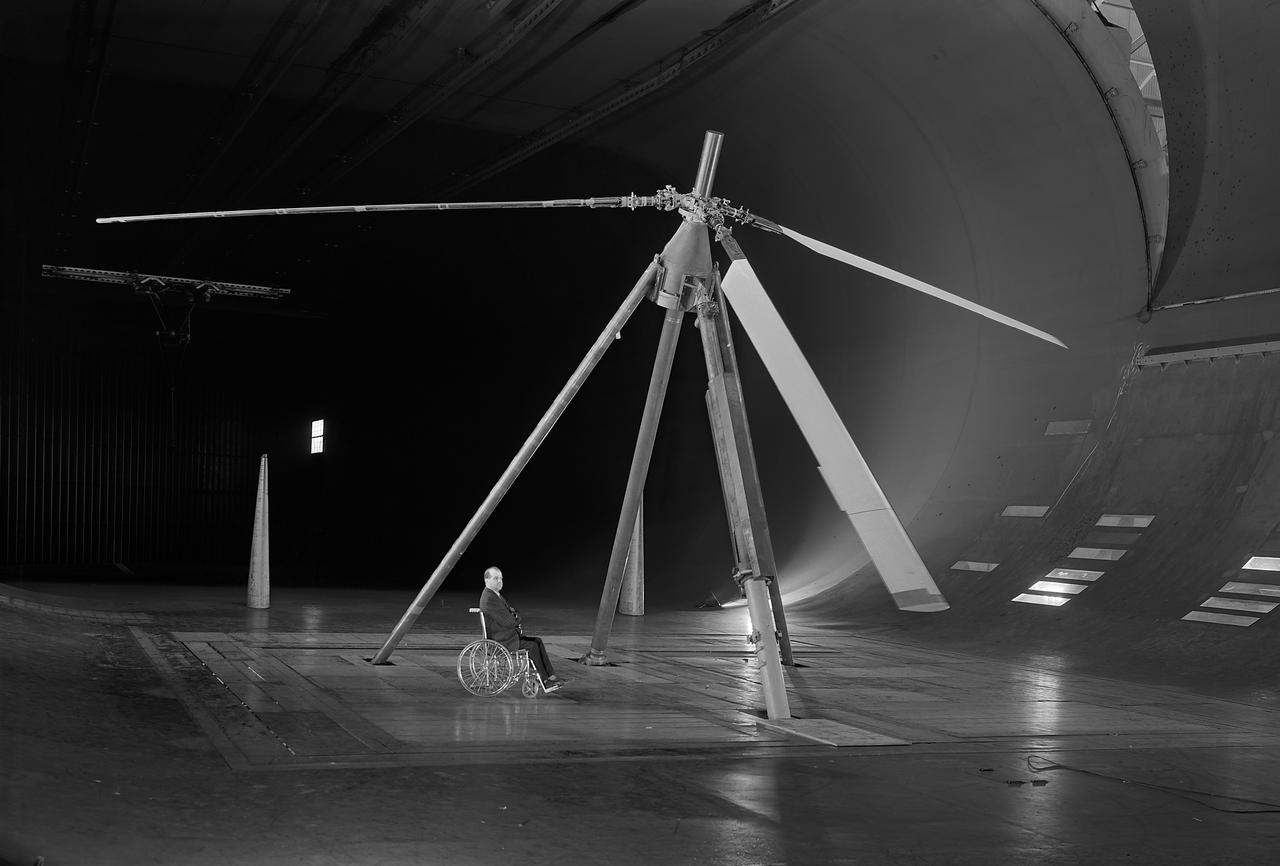
3/4 lower front view of Controllable Twist Rotor (CTR) test of 4 blade helicopter model. Pictures with Ben Mandwyler Andy Lemnios, John McCloud (wheel chair), in 40x80 foot wind tunnel. Small flaps on rotor blades.
NASA/Navy V-22 Rotor testing in the NASA Ames 40x80ft. Subsonic Wind.Tunnel. Test-568 with Fort Felker and Engenio DeVargas.
AH-1G Cobra helicopter model tail rotor flow visualization testing in 7X10ft#2 W.T. (Army tunnel - no test number)
AH-1G Cobra helicopter model tail rotor flow visualization testing in 7X10ft#2 W.T. (Army tunnel - no test number)
Rotor Entry Vehicle - force test in 12ft w.t. at Ames Research Center, Moffett Field, CA test-12-328 with J.J. Garber (ARO contractor)
NASA/Navy V-22 Rotor testing in the NASA Ames 40x80ft. Subsonic Wind.Tunnel. Test-568 with Ruth Hefferman checking specifications.
XV-15 Rotor Installation in 80X120 ft. Wind Tunnel Test-0048. Noise Reduction
XV-15 Rotor Installation in 80X120 ft. Wind Tunnel Test-0048. Noise Reduction
XV-3 in Ames Reseach Center 40x80ft wind tunnel; Rotor dynamic stability tests
XV-15 Rotor Installation in 80X120 ft. Wind Tunnel Test-0048. Noise Reduction
XV-15 Rotor Installation in 80X120 ft. Wind Tunnel Test-0048. Noise Reduction
XV-15 Rotor Installation in 80X120 ft. Wind Tunnel Test-0048. (microphone set up) Noise Reduction
XV-15 Rotor Installation in 80X120 ft. Wind Tunnel Test-0048. Noise Reduction
Assent Test (Rotor) 7x10ft#1 W.T. with engineer Frank Caradonna and Liz Hendley
Army/Sikorsky Active Rotor Test TR40-019 in teh 40x80ft wind tunnel at Ames Research Center.

ADM Swept Tip Rotor with Brian Chan in 7 x 10 ft# 1 Wind Tunnel Test-7101099.
NASA/Navy V-22 Rotor testing in the NASA Ames 40x80ft. Subsonic Wind.Tunnel with Fort Felker and Engenio DeVargas.
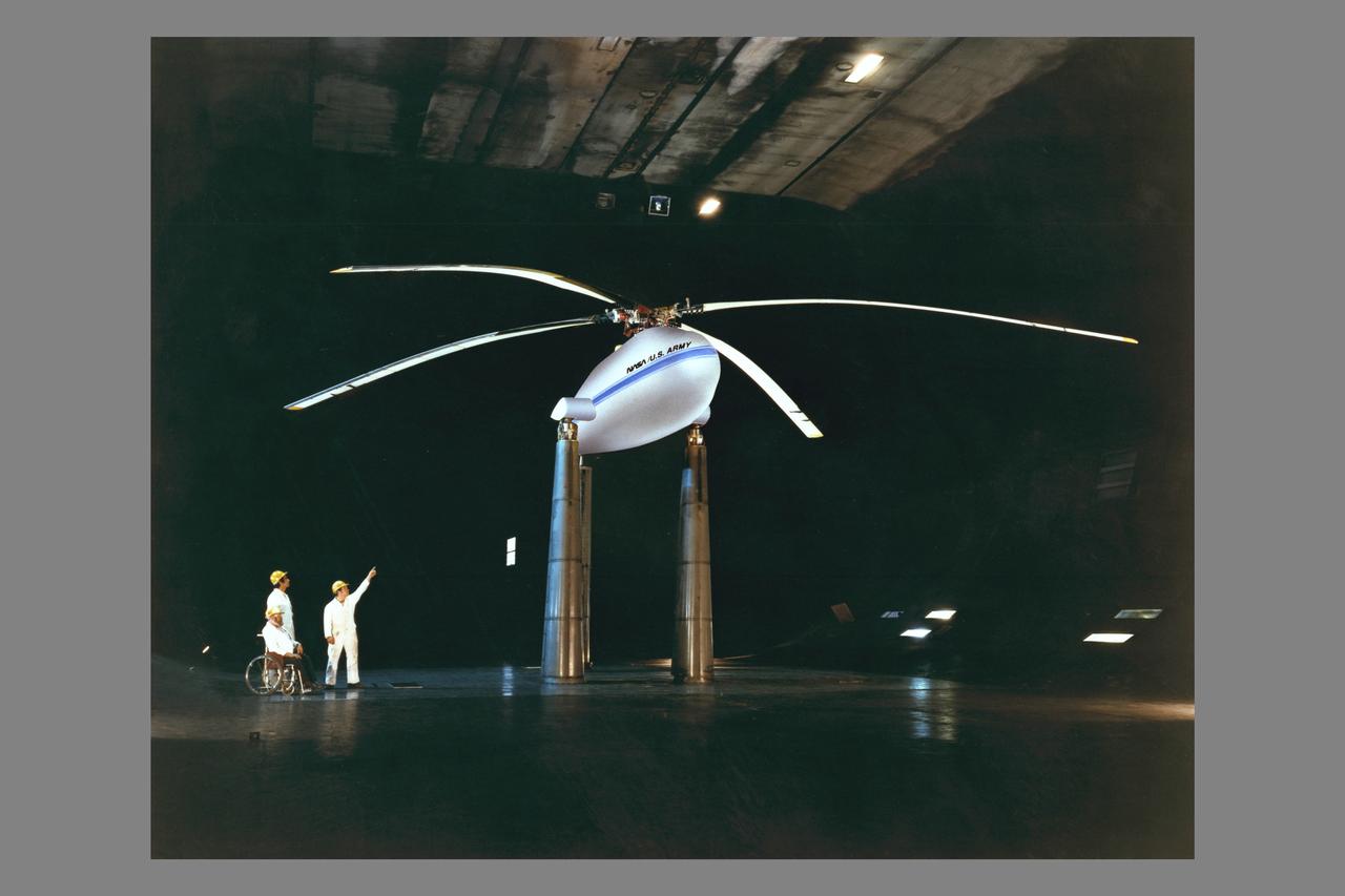
Controllable Twist Rotor test installed in 40x80ft w.t. W/B Mandwyler, A Lemnios, J McCloud, in wheelchair (airburshed image)
ADM Swept Tip Rotor in 7 x 10 ft. # 1 Wind Tunnel Test-7101099.
ADM Swept with NASA logo moved forward. ADM Swept Tip Rotor in 7 x 10ft.#1 Wind Tunnel Test-7101099.
NASA/US Army Multcyclic test rotor in the Ames 40x80ft. Subsonic Wind Tunnel, Ames Research Center, Moffett Field, CA with John Bouldt.
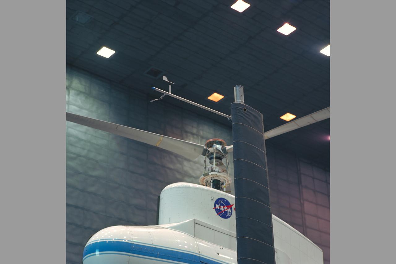
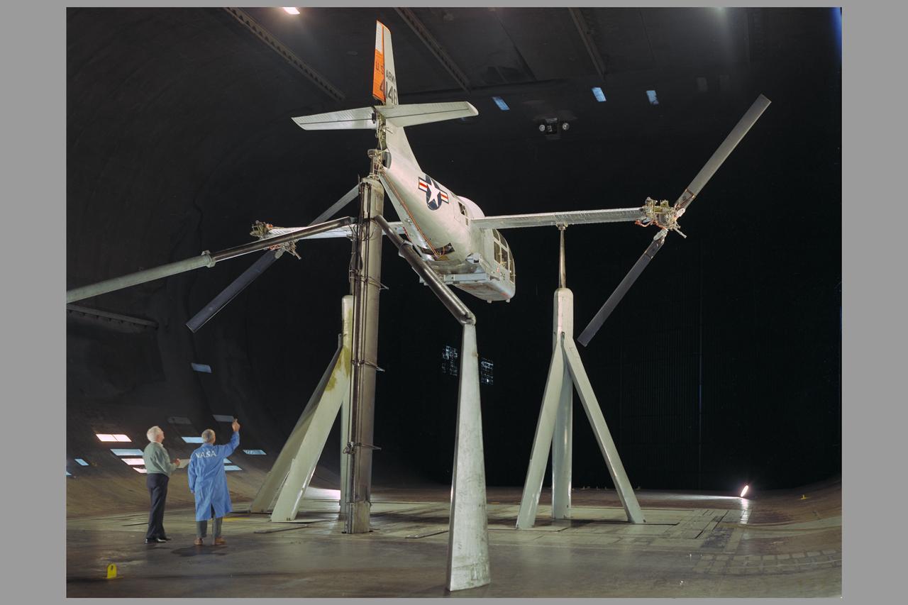
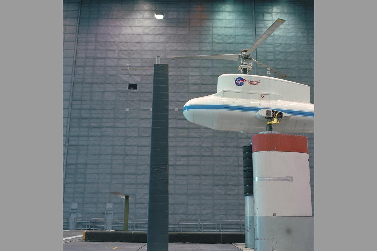
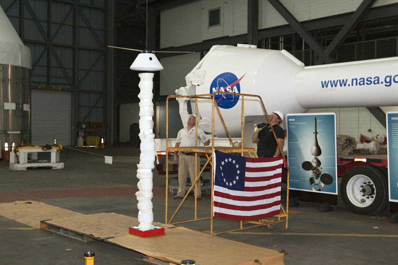
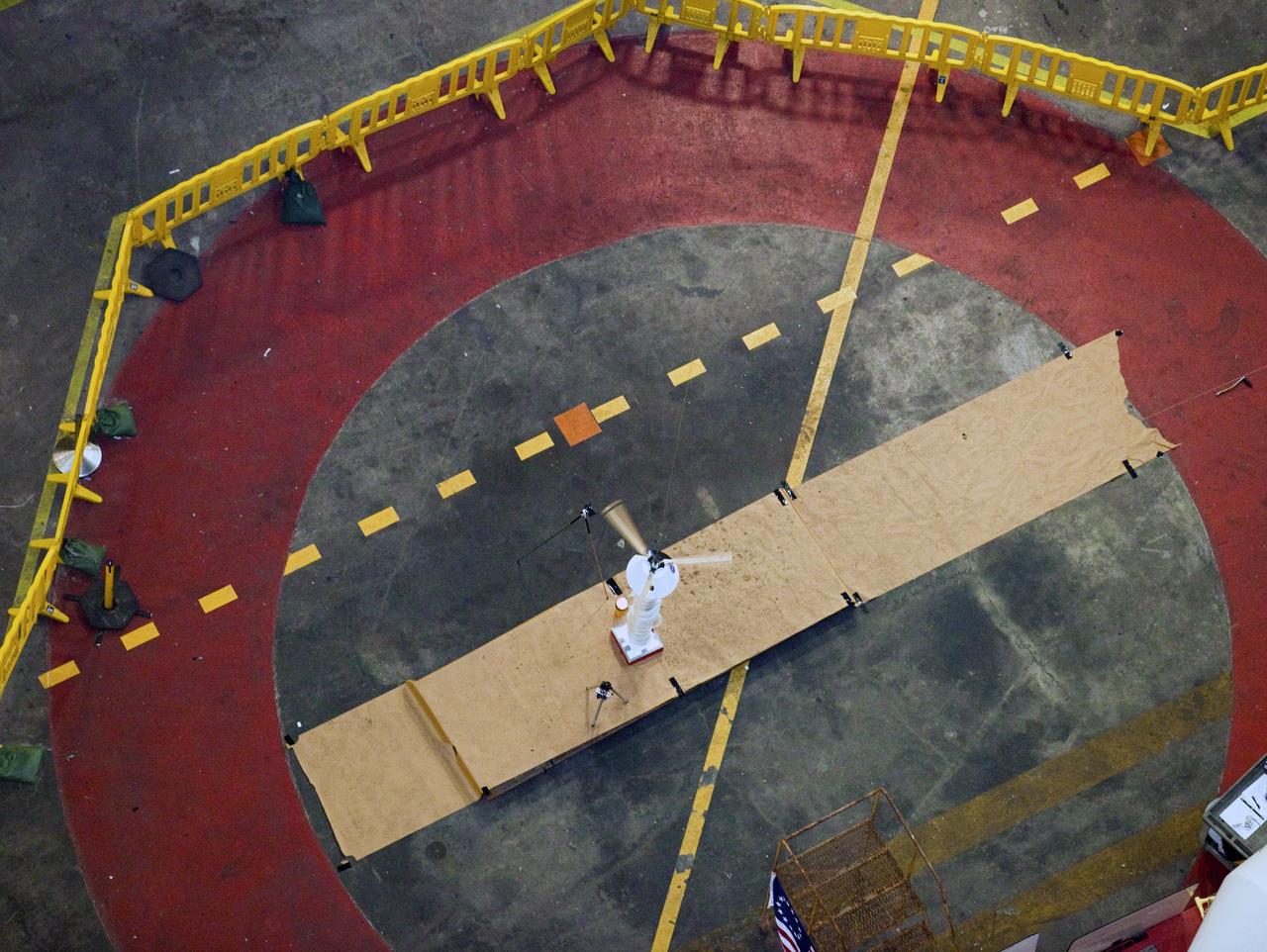
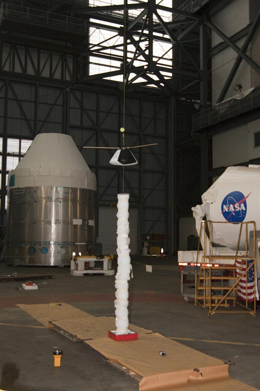
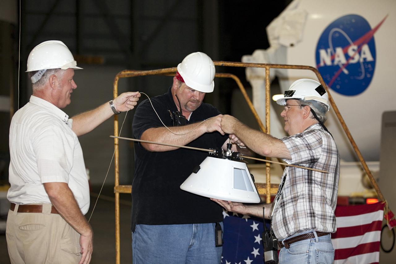
CAPE CANAVERAL, Fla. - Test operators examine a model capsule after a of test inside the Vehicle Assembly Building at NASA's Kennedy Space Center in Florida to test a rotor system landing design. The design would give a capsule the stability and control of a helicopter, but would not be powered. Instead, the wind passing over the rotors as the capsule descends would make the blades turn, a process called auto-rotation. The intent is to give real spacecraft a soft landing with enough control that they could touch down anywhere in the world, whether it be a runway or parking lot. In other words, wherever a helicopter could land, a spacecraft could land, too. Photo credit: NASA/Kim Shiflett
CAPE CANAVERAL, Fla. - Test operators prepare a model capsule ahead of tests inside the Vehicle Assembly Building at NASA's Kennedy Space Center in Florida to test a rotor system landing design. The design would give a capsule the stability and control of a helicopter, but would not be powered. Instead, the wind passing over the rotors as the capsule descends would make the blades turn, a process called auto-rotation. The intent is to give real spacecraft a soft landing with enough control that they could touch down anywhere in the world, whether it be a runway or parking lot. In other words, wherever a helicopter could land, a spacecraft could land, too. Photo credit: NASA/Kim Shiflett
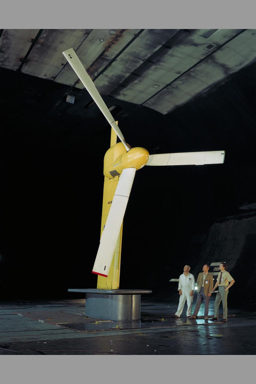
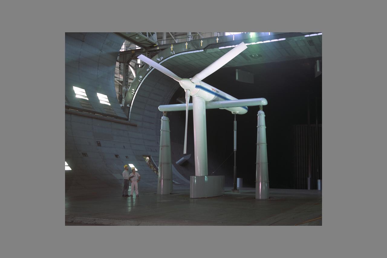
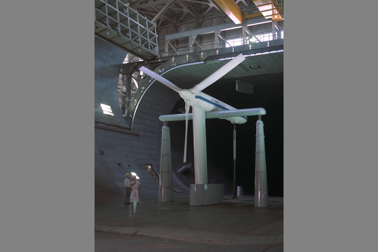
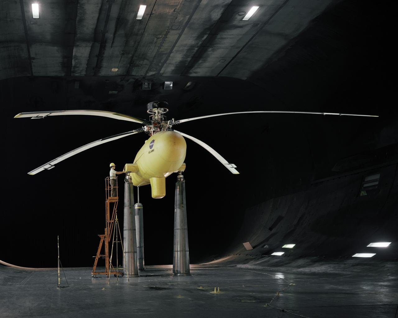
Rigid Tilt Rotor Research: Boeing 26-ft. diameter proprotor on semi-span wing in Ames Research Center 40x80ft w.t. (Photo by Ames photographer Lee Jones; composite of test results by Ames Graphics)
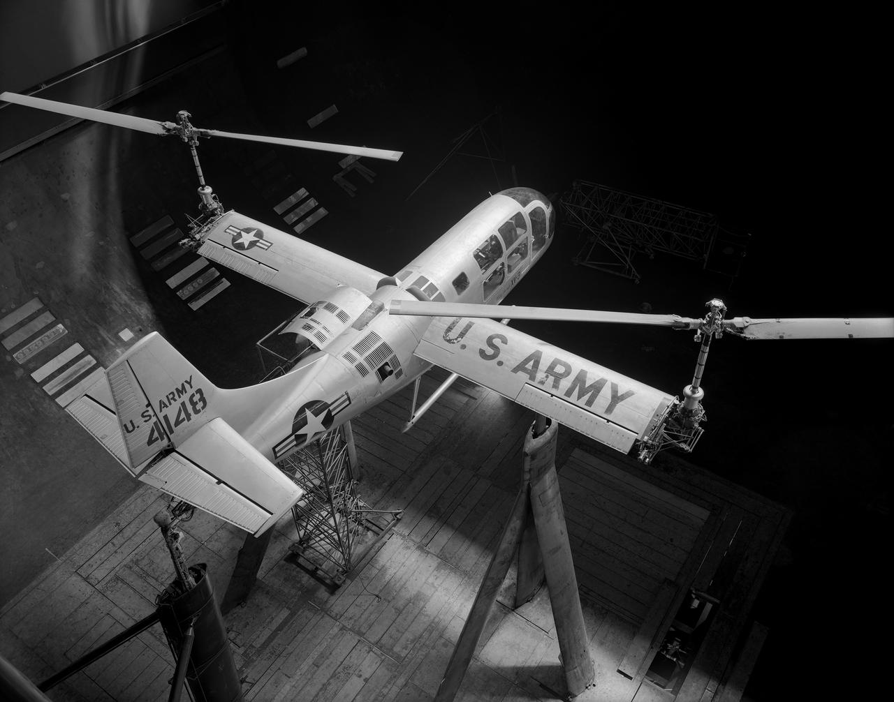
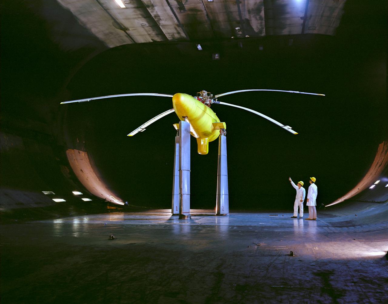
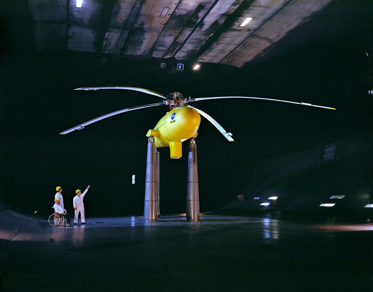
Overhead view of Bell XV-3 Convertiplane. First tilt rotor tested in the 40 x 80 wind tunnel. Transition aerodynamics studied; shown in hover mode.
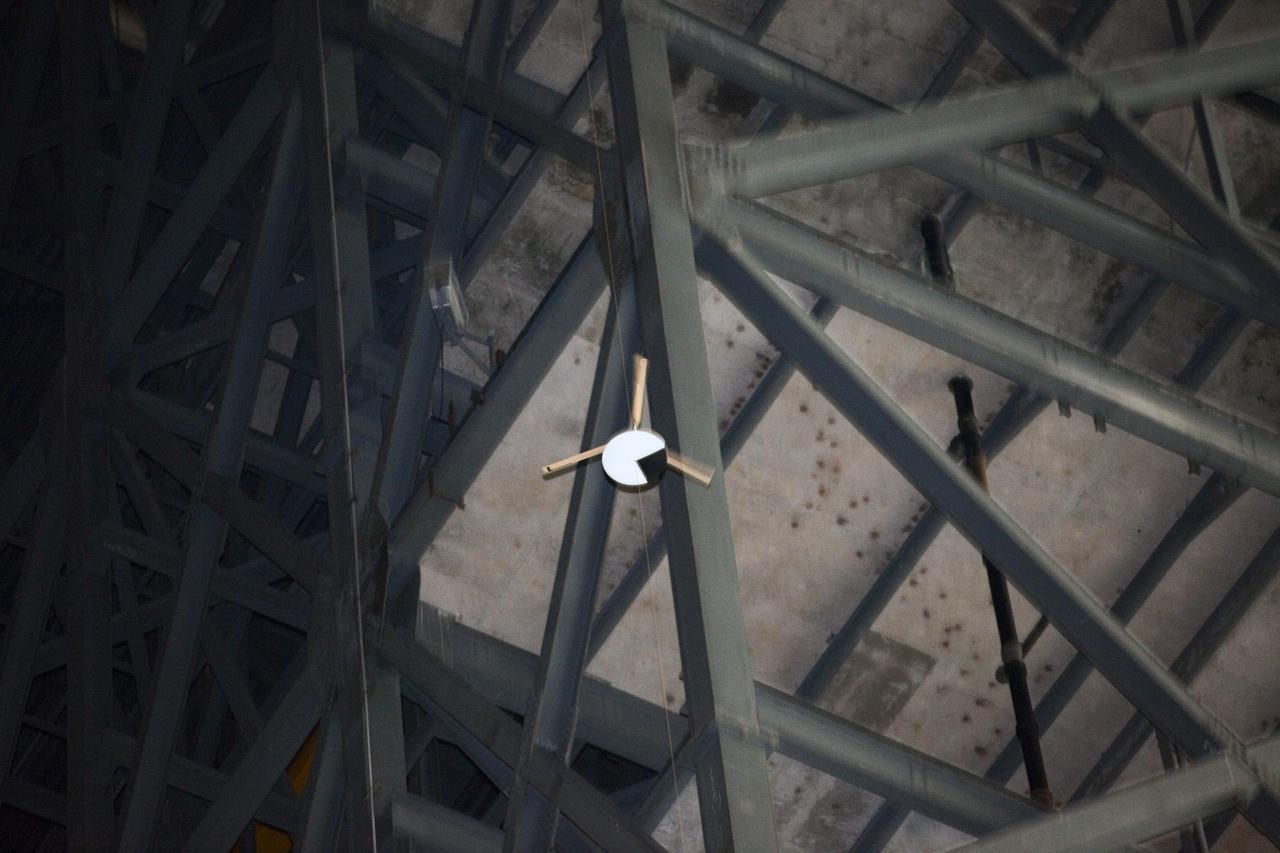
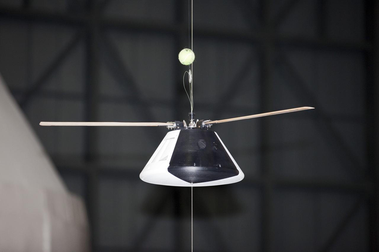
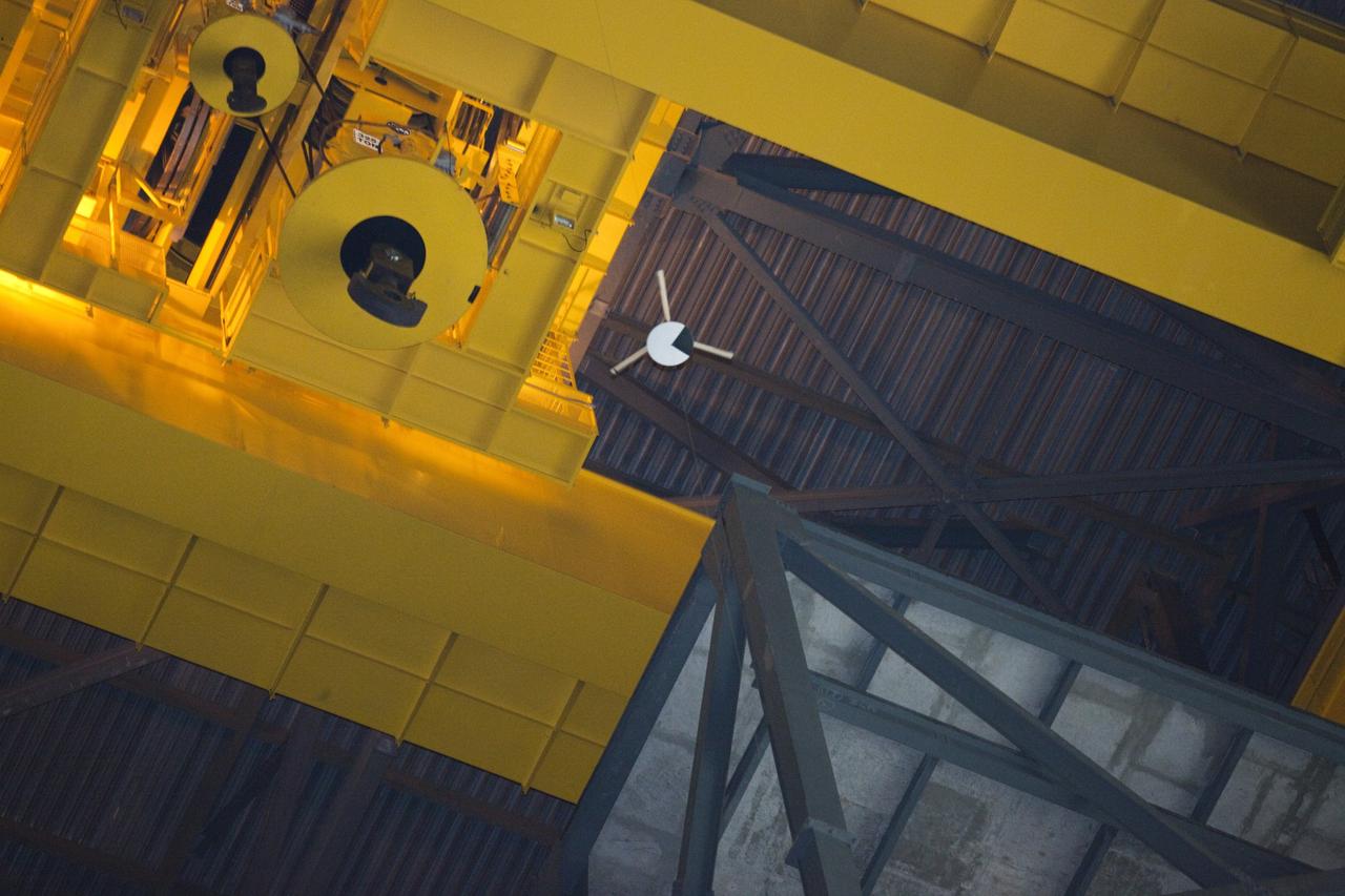
CAPE CANAVERAL, Fla. - A model capsule falls during tests inside the Vehicle Assembly Building at NASA's Kennedy Space Center in Florida to test a rotor system landing design. The design would give a capsule the stability and control of a helicopter, but would not be powered. Instead, the wind passing over the rotors as the capsule descends would make the blades turn, a process called auto-rotation. The intent is to give real spacecraft a soft landing with enough control that they could touch down anywhere in the world, whether it be a runway or parking lot. In other words, wherever a helicopter could land, a spacecraft could land, too. Photo credit: NASA/Kim Shiflett
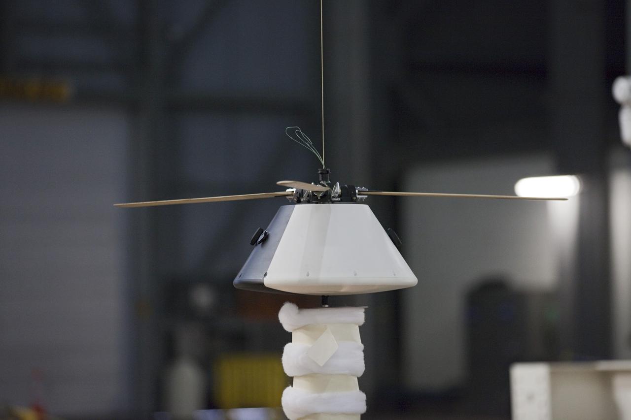
CAPE CANAVERAL, Fla. - A model capsule seen ahead of tests inside the Vehicle Assembly Building at NASA's Kennedy Space Center in Florida to test a rotor system landing design. The design would give a capsule the stability and control of a helicopter, but would not be powered. Instead, the wind passing over the rotors as the capsule descends would make the blades turn, a process called auto-rotation. The intent is to give real spacecraft a soft landing with enough control that they could touch down anywhere in the world, whether it be a runway or parking lot. In other words, wherever a helicopter could land, a spacecraft could land, too. Photo credit: NASA/Kim Shiflett
CAPE CANAVERAL, Fla. - A model capsule seen ahead of tests inside the Vehicle Assembly Building at NASA's Kennedy Space Center in Florida to test a rotor system landing design. The design would give a capsule the stability and control of a helicopter, but would not be powered. Instead, the wind passing over the rotors as the capsule descends would make the blades turn, a process called auto-rotation. The intent is to give real spacecraft a soft landing with enough control that they could touch down anywhere in the world, whether it be a runway or parking lot. In other words, wherever a helicopter could land, a spacecraft could land, too. Photo credit: NASA/Kim Shiflett
CAPE CANAVERAL, Fla. - A model capsule seen ahead of tests inside the Vehicle Assembly Building at NASA's Kennedy Space Center in Florida to test a rotor system landing design. The design would give a capsule the stability and control of a helicopter, but would not be powered. Instead, the wind passing over the rotors as the capsule descends would make the blades turn, a process called auto-rotation. The intent is to give real spacecraft a soft landing with enough control that they could touch down anywhere in the world, whether it be a runway or parking lot. In other words, wherever a helicopter could land, a spacecraft could land, too. Photo credit: NASA/Kim Shiflett
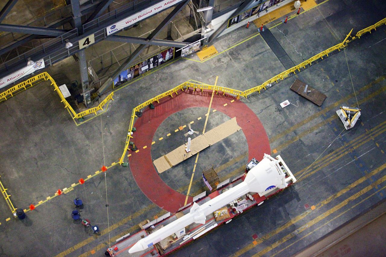
CAPE CANAVERAL, Fla. - A model capsule following a test inside the Vehicle Assembly Building at NASA's Kennedy Space Center in Florida to test a rotor system landing design. The design would give a capsule the stability and control of a helicopter, but would not be powered. Instead, the wind passing over the rotors as the capsule descends would make the blades turn, a process called auto-rotation. The intent is to give real spacecraft a soft landing with enough control that they could touch down anywhere in the world, whether it be a runway or parking lot. In other words, wherever a helicopter could land, a spacecraft could land, too. Photo credit: NASA/Kim Shiflett
CAPE CANAVERAL, Fla. - A model capsule falls during tests inside the Vehicle Assembly Building at NASA's Kennedy Space Center in Florida to test a rotor system landing design. The design would give a capsule the stability and control of a helicopter, but would not be powered. Instead, the wind passing over the rotors as the capsule descends would make the blades turn, a process called auto-rotation. The intent is to give real spacecraft a soft landing with enough control that they could touch down anywhere in the world, whether it be a runway or parking lot. In other words, wherever a helicopter could land, a spacecraft could land, too. Photo credit: NASA/Kim Shiflett
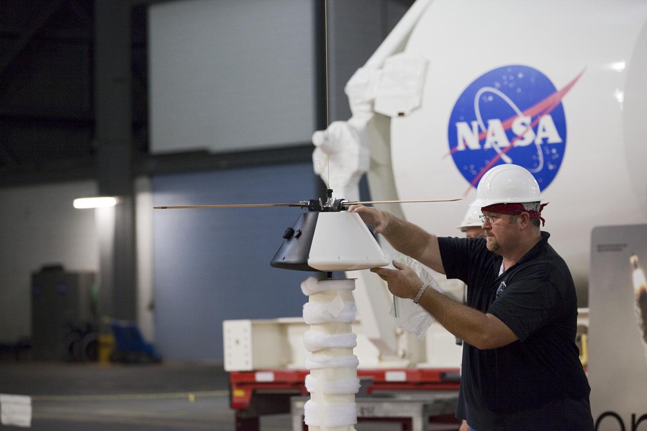
CAPE CANAVERAL, Fla. - NASA Aerospace Engineer Jeff Hagen prepares a model capsule ahead of tests inside the Vehicle Assembly Building at NASA's Kennedy Space Center in Florida to test a rotor system landing design. The design would give a capsule the stability and control of a helicopter, but would not be powered. Instead, the wind passing over the rotors as the capsule descends would make the blades turn, a process called auto-rotation. The intent is to give real spacecraft a soft landing with enough control that they could touch down anywhere in the world, whether it be a runway or parking lot. In other words, wherever a helicopter could land, a spacecraft could land, too. Photo credit: NASA/Kim Shiflett
CAPE CANAVERAL, Fla. - A model capsule seen ahead of tests inside the Vehicle Assembly Building at NASA's Kennedy Space Center in Florida to test a rotor system landing design. The design would give a capsule the stability and control of a helicopter, but would not be powered. Instead, the wind passing over the rotors as the capsule descends would make the blades turn, a process called auto-rotation. The intent is to give real spacecraft a soft landing with enough control that they could touch down anywhere in the world, whether it be a runway or parking lot. In other words, wherever a helicopter could land, a spacecraft could land, too. Photo credit: NASA/Kim Shiflett
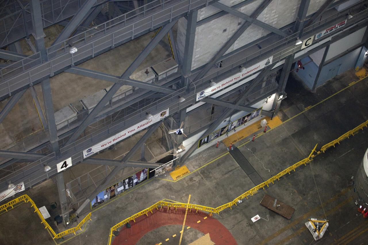
CAPE CANAVERAL, Fla. - A model capsule falls during tests inside the Vehicle Assembly Building at NASA's Kennedy Space Center in Florida to test a rotor system landing design. The design would give a capsule the stability and control of a helicopter, but would not be powered. Instead, the wind passing over the rotors as the capsule descends would make the blades turn, a process called auto-rotation. The intent is to give real spacecraft a soft landing with enough control that they could touch down anywhere in the world, whether it be a runway or parking lot. In other words, wherever a helicopter could land, a spacecraft could land, too. Photo credit: NASA/Kim Shiflett
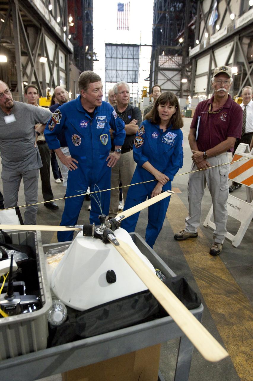
CAPE CANAVERAL, Fla. - Astronauts Mike Fossum and Cady Coleman look over a model capsule fit with rotor blades ahead of tests inside the Vehicle Assembly Building at NASA's Kennedy Space Center in Florida. The design would give a capsule the stability and control of a helicopter, but would not be powered. Instead, the wind passing over the rotors as the capsule descends would make the blades turn, a process called auto-rotation. The intent is to give real spacecraft a soft landing with enough control that they could touch down anywhere in the world, whether it be a runway or parking lot. In other words, wherever a helicopter could land, a spacecraft could land, too. Photo credit: NASA/Kim Shiflett
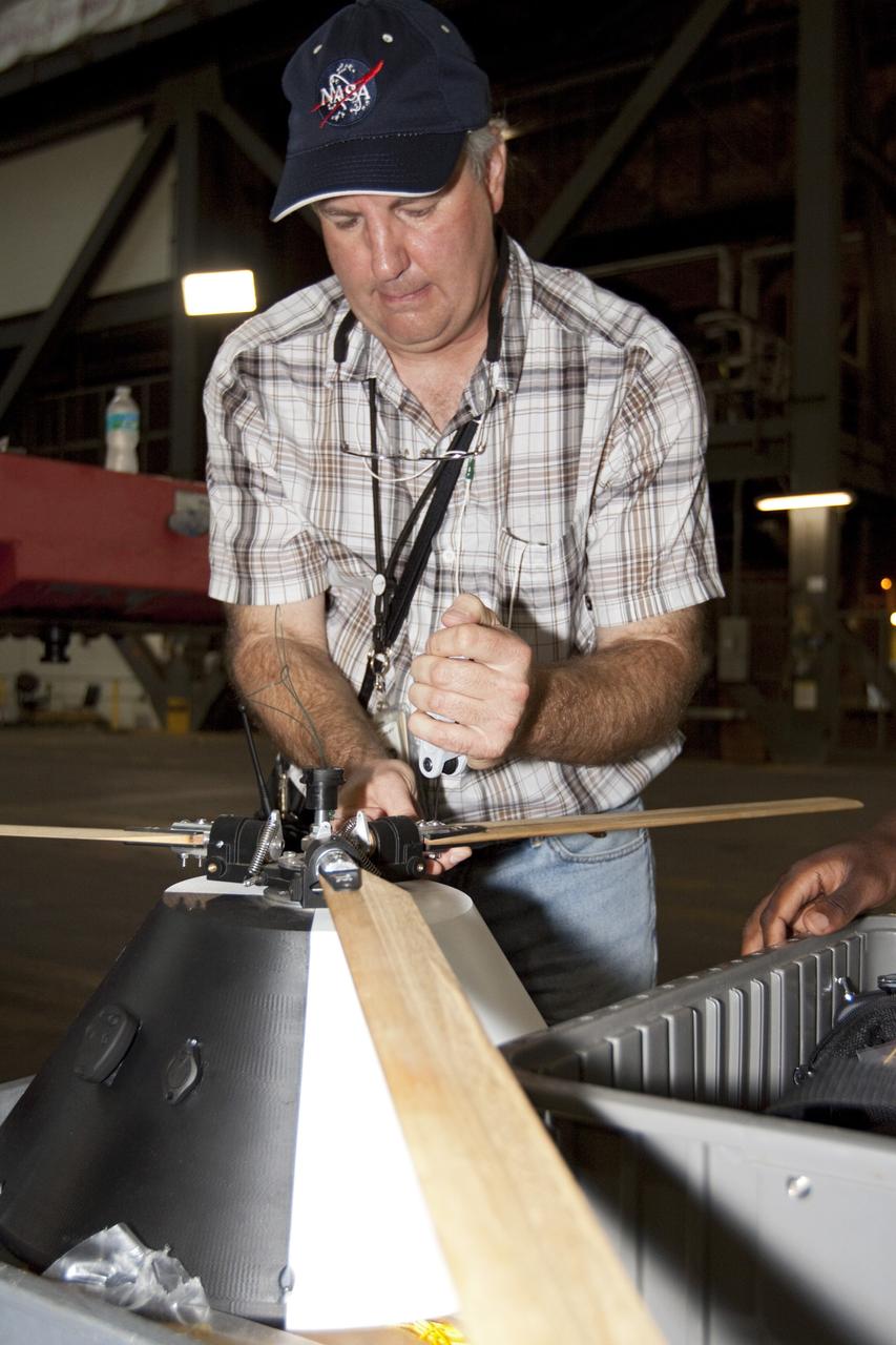
CAPE CANAVERAL, Fla. - NASA's Johnson Space Center Aerospace Engineer Jeff Hagen attaches a rotor to the top of a model capsule ahead of tests inside the Vehicle Assembly Building at NASA's Kennedy Space Center in Florida. The design would give a capsule the stability and control of a helicopter, but would not be powered. Instead, the wind passing over the rotors as the capsule descends would make the blades turn, a process called auto-rotation. The intent is to give real spacecraft a soft landing with enough control that they could touch down anywhere in the world, whether it be a runway or parking lot. In other words, wherever a helicopter could land, a spacecraft could land, too. Photo credit: NASA/Kim Shiflett

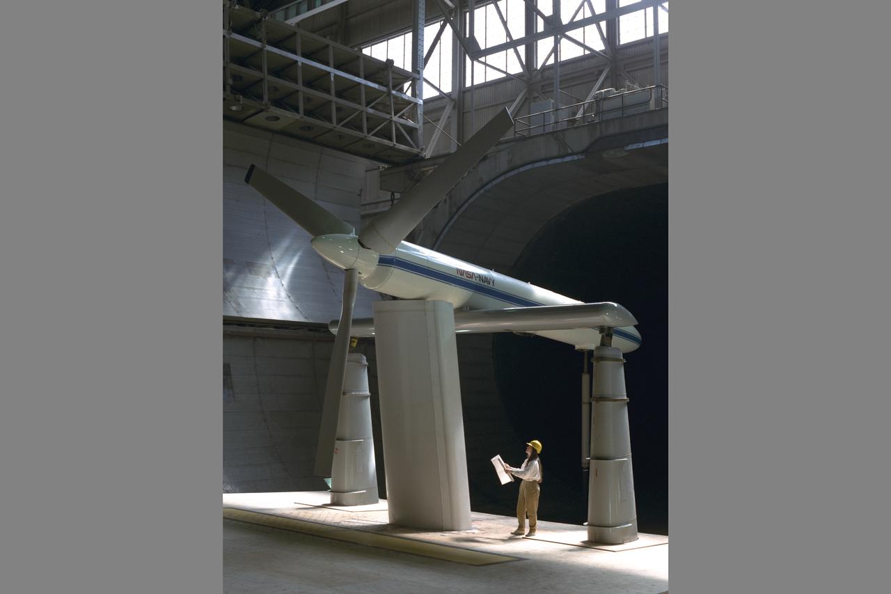
The XV-15 tilt rotor ships #1 and #2 parked on the NASA Dryden Flight Research Center ramp. The XV-15s, manufactured by Bell, were involved in limited research at Dryden in 1980 and 1981. The development of the XV-15 Tiltrotor research aircraft was initiated in 1973 with joint Army/NASA funding as a "proof of concept", or "technology demonstrator" program, with two aircraft being built by Bell Helicopter Textron (BHT) in 1977. The aircraft are powered by twin Lycoming T-53 turboshaft engines that are connected by a cross-shaft and drive three-bladed, 25 ft diameter metal rotors (the size extensively tested in a wind tunnel). The engines and main transmissions are located in wingtip nacelles to minimize the operational loads on the cross-shaft system and, with the rotors, tilt as a single unit. For takeoff, the proprotors and their engines are used in the straight-up position where the thrust is directed downward. The XV-15 then climbs vertically into the air like a helicopter. In this VTOL mode, the vehicle can lift off and hover for approximately one hour. Once off the ground, the XV-15 has the ability to fly in one of two different modes. It can fly as a helicopter, in the partially converted airplane mode. The XV-15 can also then convert from the helicopter mode to the airplane mode. This is accomplished by continuous rotation of the proprotors from the helicopter rotor position to the conventional airplane propeller position. During the ten to fifteen second conversion period, the aircraft speed increases and lift is transferred from the rotors to the wing. To land, the proprotors are rotated up to the helicopter rotor position and flown as a helicopter to a vertical landing.
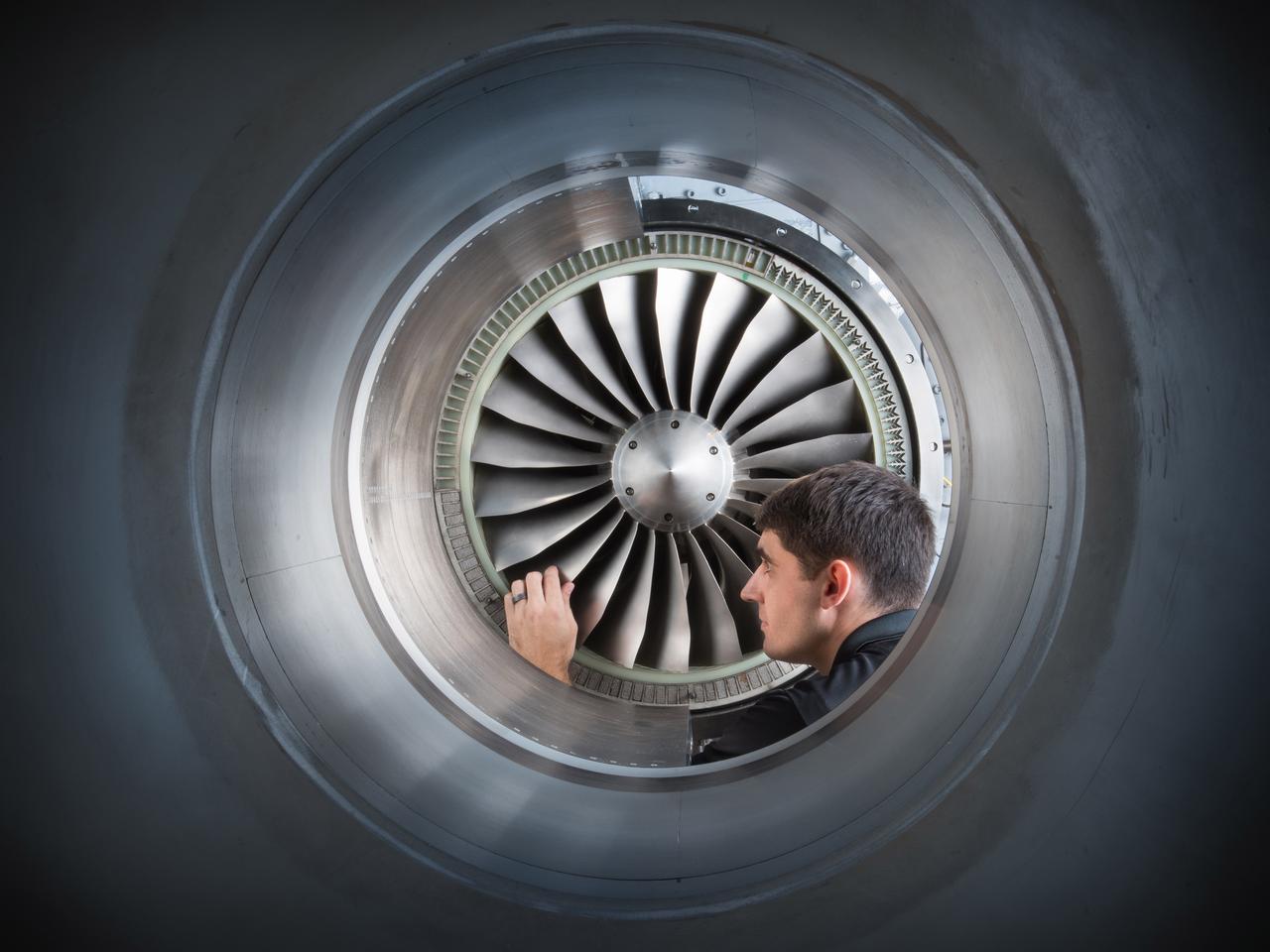
Acoustic Casing Treatment Testing Completed in the W-8 Single Stage Axial Compressor Facility at NASA Glenn. Four different over-the-rotor acoustic casing treatment concepts were tested along with two baseline configurations. Testing included steady-aerodynamic measurements of fan performance, hotfilm turbulence measurements, and inlet acoustic measurements with an in-duct array.
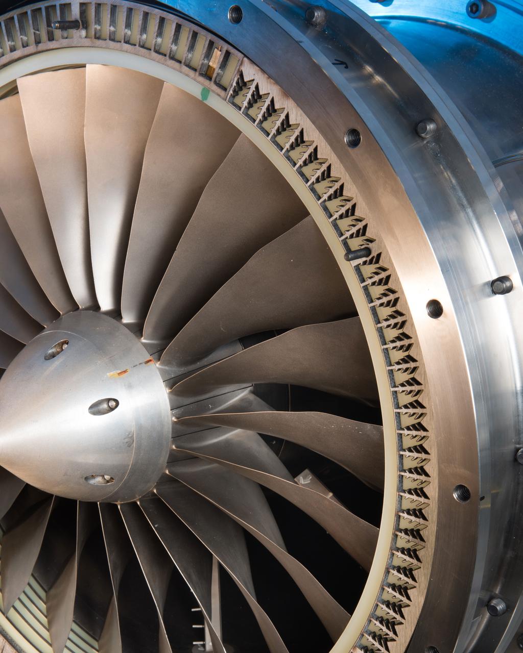
Acoustic Casing Treatment Testing Completed in the W-8 Single Stage Axial Compressor Facility at NASA Glenn. Four different over-the-rotor acoustic casing treatment concepts were tested along with two baseline configurations. Testing included steady-aerodynamic measurements of fan performance, hotfilm turbulence measurements, and inlet acoustic measurements with an in-duct array.

Test of Unmanned Aircraft Systems Traffic Management (UTM) technical capability Level 2 (TCL2) at Reno-Stead Airport, Nevada. During the test, five drones simultaneously crossed paths, separated by altitude. Two drones flew beyond visual line-of-sight and three flew within line-of-sight of their operators. Drone Co-habitation Services operates a Phantom 3 commercial multi-rotor unmanned aircraft, one of 11 vehicles in the UTM TCL2 demonstration that will fly beyond line of sight of the pilot in command in Nevada test.
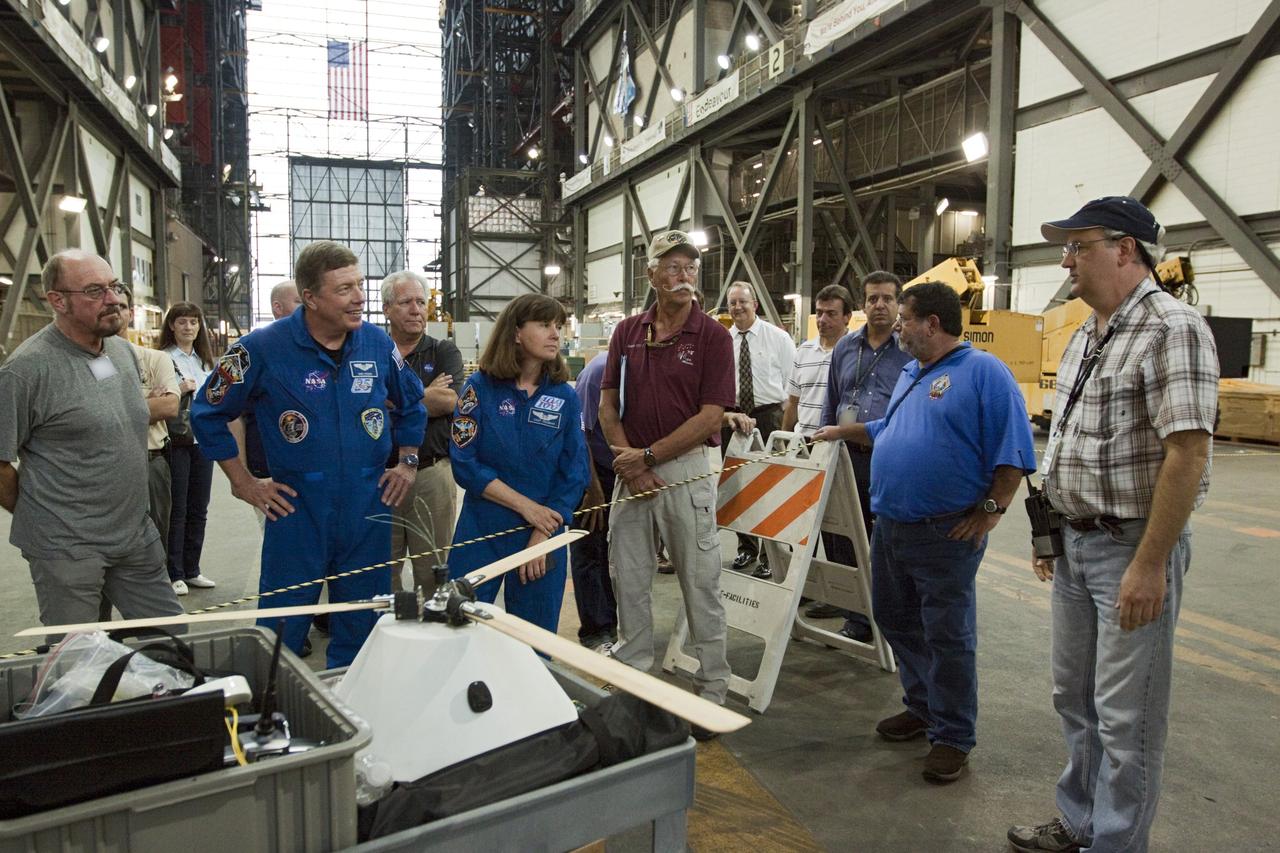
CAPE CANAVERAL, Fla. - Astronauts Mike Fossum and Cady Coleman, both in blue flight suits, look over the model capsule fit with rotor blades ahead of tests inside the Vehicle Assembly Building at NASA's Kennedy Space Center in Florida. NASA's Johnson Space Center Aerospace Engineer Jeff Hagen, right, fields questions about the project. The design would give a capsule the stability and control of a helicopter, but would not be powered. Instead, the wind passing over the rotors as the capsule descends would make the blades turn, a process called auto-rotation. The intent is to give real spacecraft a soft landing with enough control that they could touch down anywhere in the world, whether it be a runway or parking lot. In other words, wherever a helicopter could land, a spacecraft could land, too. Photo credit: NASA/Kim Shiflett
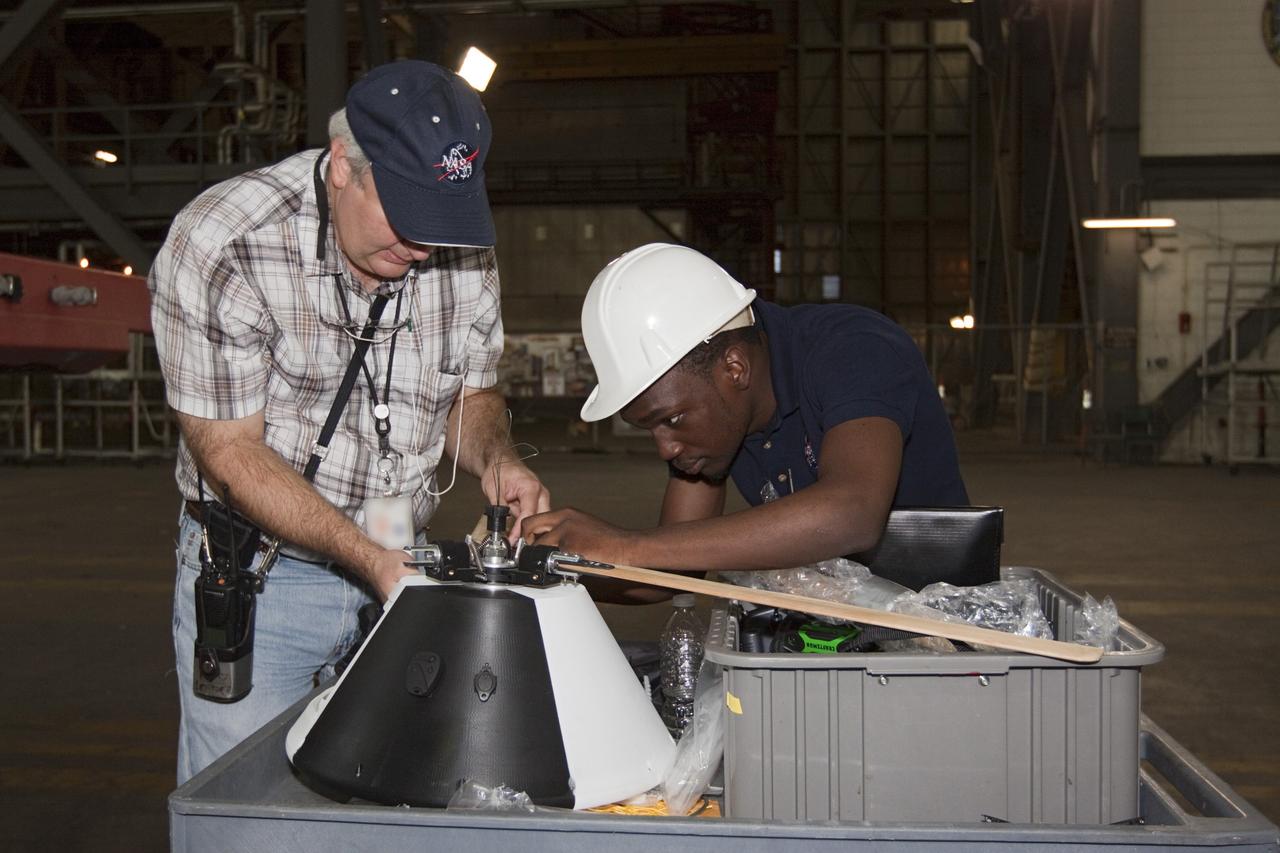
CAPE CANAVERAL, Fla. - NASA's Johnson Space Center Aerospace Engineer Jeff Hagen, left, and engineering intern Emmanuel Nyangweso attach rotors to the top of a model capsule ahead of tests inside the Vehicle Assembly Building at NASA's Kennedy Space Center in Florida. The design would give a capsule the stability and control of a helicopter, but would not be powered. Instead, the wind passing over the rotors as the capsule descends would make the blades turn, a process called auto-rotation. The intent is to give real spacecraft a soft landing with enough control that they could touch down anywhere in the world, whether it be a runway or parking lot. In other words, wherever a helicopter could land, a spacecraft could land, too. Photo credit: NASA/Kim Shiflett
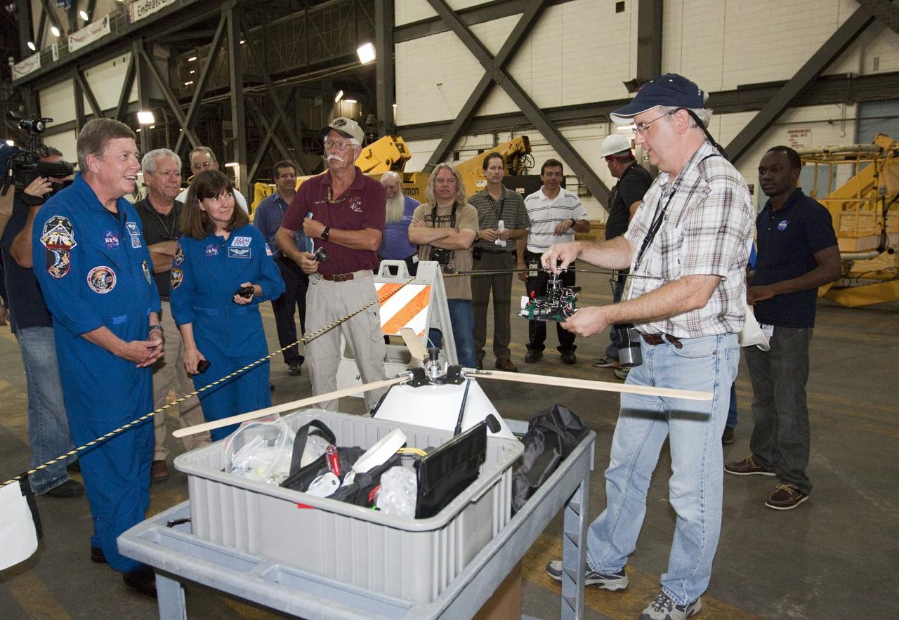
CAPE CANAVERAL, Fla. - Astronauts Mike Fossum and Cady Coleman, both in blue flight suits, listen as NASA's Johnson Space Center Aerospace Engineer Jeff Hagen explains the rotor mechanism for a model capsule ahead of tests inside the Vehicle Assembly Building at NASA's Kennedy Space Center in Florida. The design would give a capsule the stability and control of a helicopter, but would not be powered. Instead, the wind passing over the rotors as the capsule descends would make the blades turn, a process called auto-rotation. The intent is to give real spacecraft a soft landing with enough control that they could touch down anywhere in the world, whether it be a runway or parking lot. In other words, wherever a helicopter could land, a spacecraft could land, too. Photo credit: NASA/Kim Shiflett
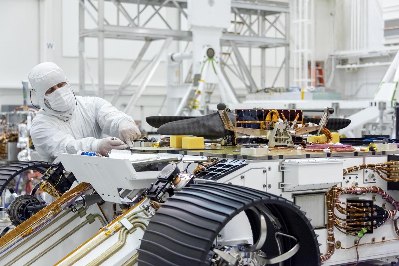
An engineer works on attaching NASA's Mars Helicopter to the belly of the Mars 2020 rover — which has been flipped over for that purpose — on Aug. 28, 2019, at the Jet Propulsion Laboratory in Pasadena, California. The twin-rotor, solar-powered helicopter was mechanically connected, along with the Mars Helicopter Delivery System, to a plate on the rover's belly that includes a cover to shield the helicopter from debris during entry, descent and landing. The helicopter will remain encapsulated after landing, deploying to the surface once a suitable area to conduct test flights is found at Jezero Crater, the rover's destination. https://photojournal.jpl.nasa.gov/catalog/PIA23372
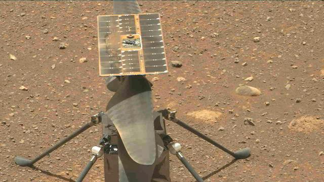
The Ingenuity Mars Helicopter's carbon fiber blades can be seen in this video taken by the Mastcam-Z instrument aboard NASA's Perseverance Mars rover on April 8, 2021, the 48th Martian day, or sol, of the mission. The four blades are arranged into two 4-foot-long (1.2-meter-long) counter-rotating rotors that can spin at roughly 2,400 rpm. The video shows the blades performing a wiggle test before the actual spin-up to ensure they were working properly. The helicopter weighs about 4 pounds (1.8 kilograms) on Earth, and about 1.5 pounds (0.68 kilograms) on Mars. It stands 1.6 feet (0.49 meters) high. It's four specially made carbon fiber blades are arranged into two 4-foot-long (1.2-meter-long) counter-rotating rotors that spin at roughly 2,400 rpm. The helicopter's fuselage is 5.4 inches by 7.7 inches by 6.4 inches (13.6 centimeters by 19.5 centimeters by 16.3 centimeters); it has four carbon composite landing legs, each 1.26 feet (0.384 meters) long, giving the helicopter about 5 inches (13 centimeters) of clearance above the ground. It is powered by a solar array on top of the rotor system, which charges six lithium-ion batteries A key objective for Perseverance's mission on Mars is astrobiology, including the search for signs of ancient microbial life. The rover will characterize the planet's geology and past climate, pave the way for human exploration of the Red Planet, and be the first mission to collect and cache Martian rock and regolith (broken rock and dust). Subsequent NASA missions, in cooperation with ESA (European Space Agency), would send spacecraft to Mars to collect these sealed samples from the surface and return them to Earth for in-depth analysis. The Mars 2020 Perseverance mission is part of NASA's Moon to Mars exploration approach, which includes Artemis missions to the Moon that will help prepare for human exploration of the Red Planet. Animation available at https://photojournal.jpl.nasa.gov/catalog/PIA24549
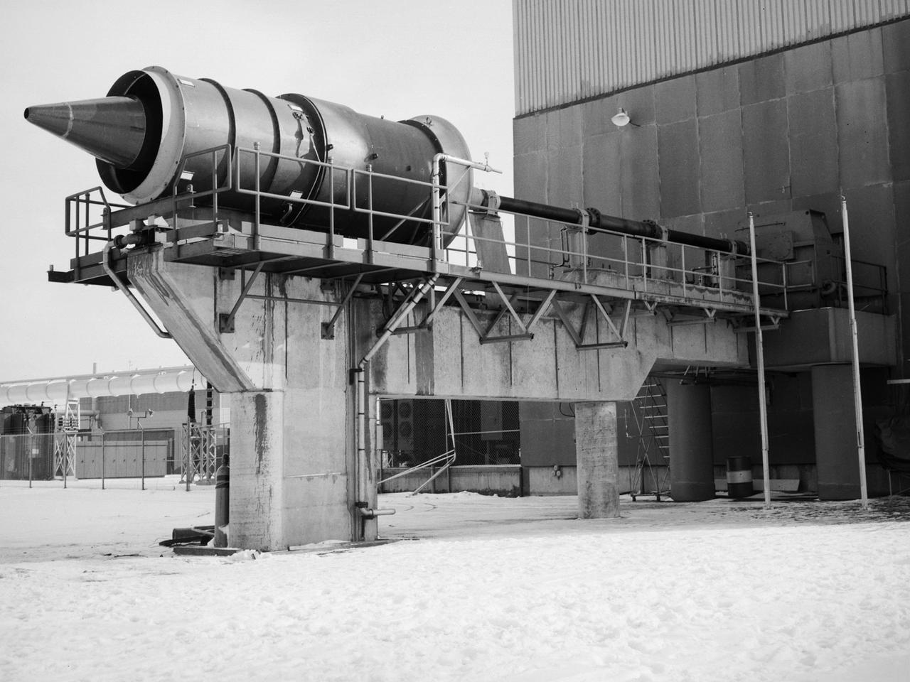
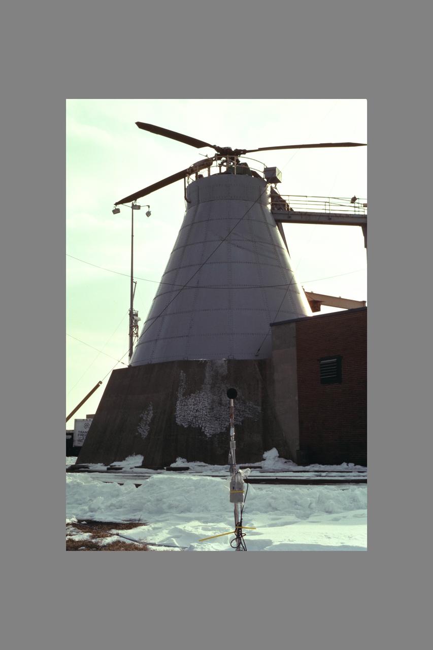
The Fan Noise Test Facility built at the Lewis Research Center to obtain far-field noise data for the National Aeronautics and Space Administration (NASA) and General Electric Quiet Engine Program. The engine incorporated existing noise reduction methods into an engine of similar power to those that propelled the Boeing 707 or McDonnell-Douglas DC-8 airliner. The new the low-bypass ratio turbofan engines of the 1960s were inherently quieter than their turbojet counterparts, researchers had a better grasp of the noise generation problem, and new acoustic technologies had emerged. Lewis contracted General Electric in 1969 to build and aerodynamically test three experimental engines with 72-inch diameter fans. The engines were then brought to Lewis and tested with an acoustically treated nacelle. This Fan Noise Test Facility was built off of the 10- by 10-Foot Supersonic Wind Tunnel’s Main Compressor and Drive Building. Lewis researchers were able to isolate the fan’s noise during these initial tests by removing the core of the engine. The Lewis test rig drove engines to takeoff tip speeds of 1160 feet per second. The facility was later used to test a series of full-scale model fans and fan noise suppressors to be used with the quiet engine. NASA researchers predicted low-speed single-stage fans without inlet guide vanes and with large spacing between rotors and stators would be quieter. General Electric modified a TF39 turbofan engine by removing the the outer protion of the fan and spacing the blade rows of the inner portion. The tests revealed that the untreated version of the engine generated less noise than was anticipated, and the acoustically treated nacelle substantially reduced engine noise.
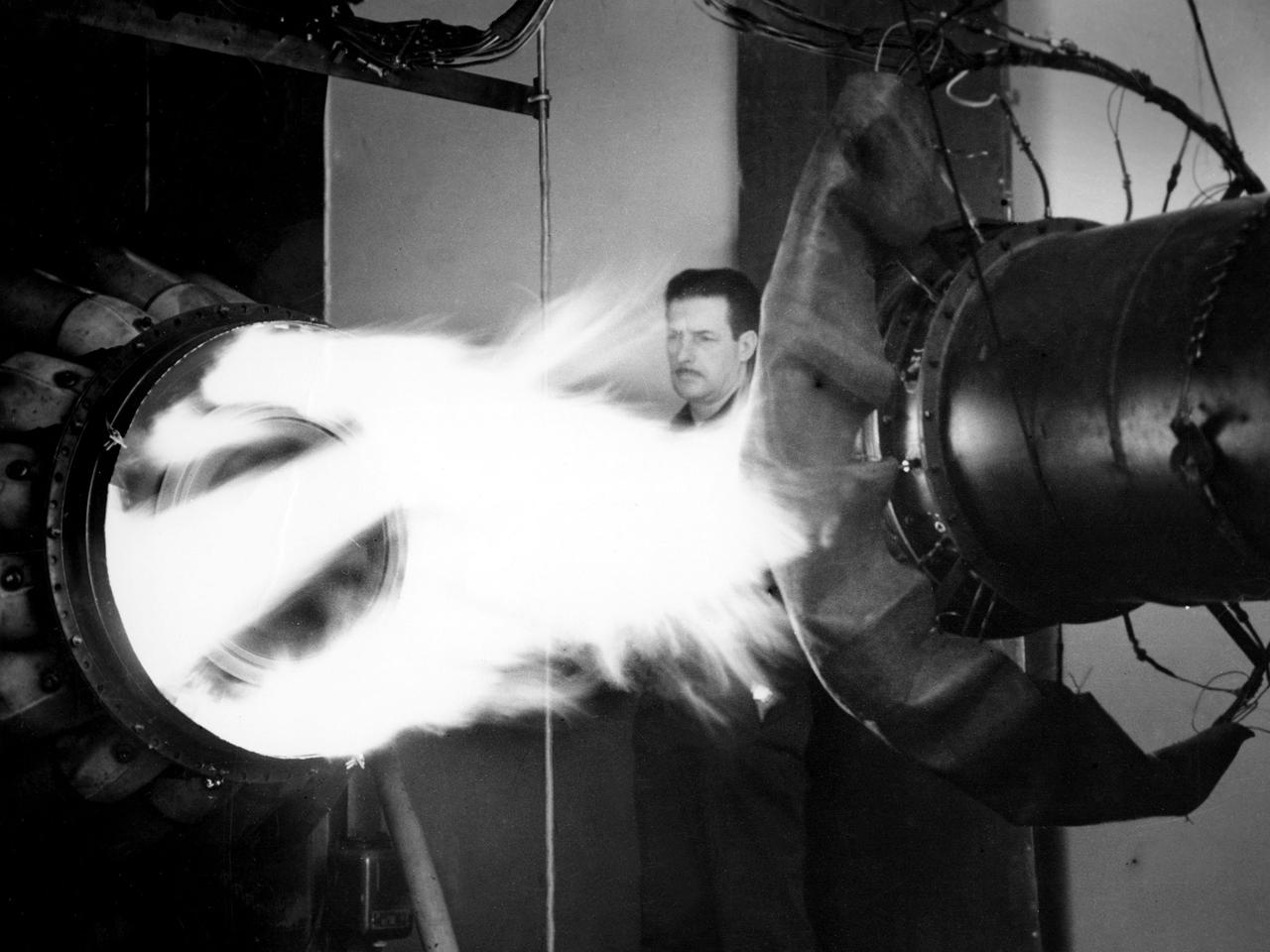
A mechanic watches the firing of a General Electric I-40 turbojet at the National Advisory Committee for Aeronautics (NACA) Lewis Flight Propulsion Laboratory. The military selected General Electric’s West Lynn facility in 1941 to secretly replicate the centrifugal turbojet engine designed by British engineer Frank Whittle. General Electric’s first attempt, the I-A, was fraught with problems. The design was improved somewhat with the subsequent I-16 engine. It was not until the engine's next reincarnation as the I-40 in 1943 that General Electric’s efforts paid off. The 4000-pound thrust I-40 was incorporated into the Lockheed Shooting Star airframe and successfully flown in June 1944. The Shooting Star became the US’s first successful jet aircraft and the first US aircraft to reach 500 miles per hour. NACA Lewis studied all of General Electric’s centrifugal turbojet models during the 1940s. In 1945 the entire Shooting Star aircraft was investigated in the Altitude Wind Tunnel. Engine compressor performance and augmentation by water injection; comparison of different fuel blends in a single combustor; and air-cooled rotors were studied. The mechanic in this photograph watches the firing of a full-scale I-40 in the Jet Propulsion Static Laboratory. The facility was quickly built in 1943 specifically in order to test the early General Electric turbojets. The I-A was secretly analyzed in the facility during the fall of 1943.