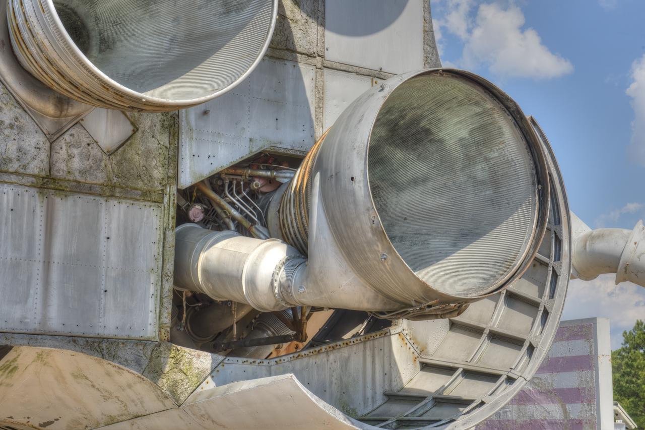
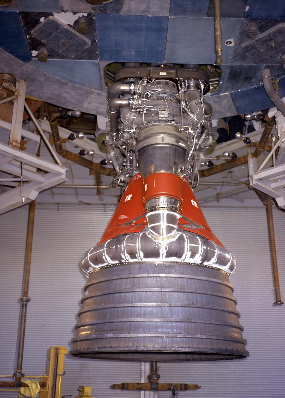
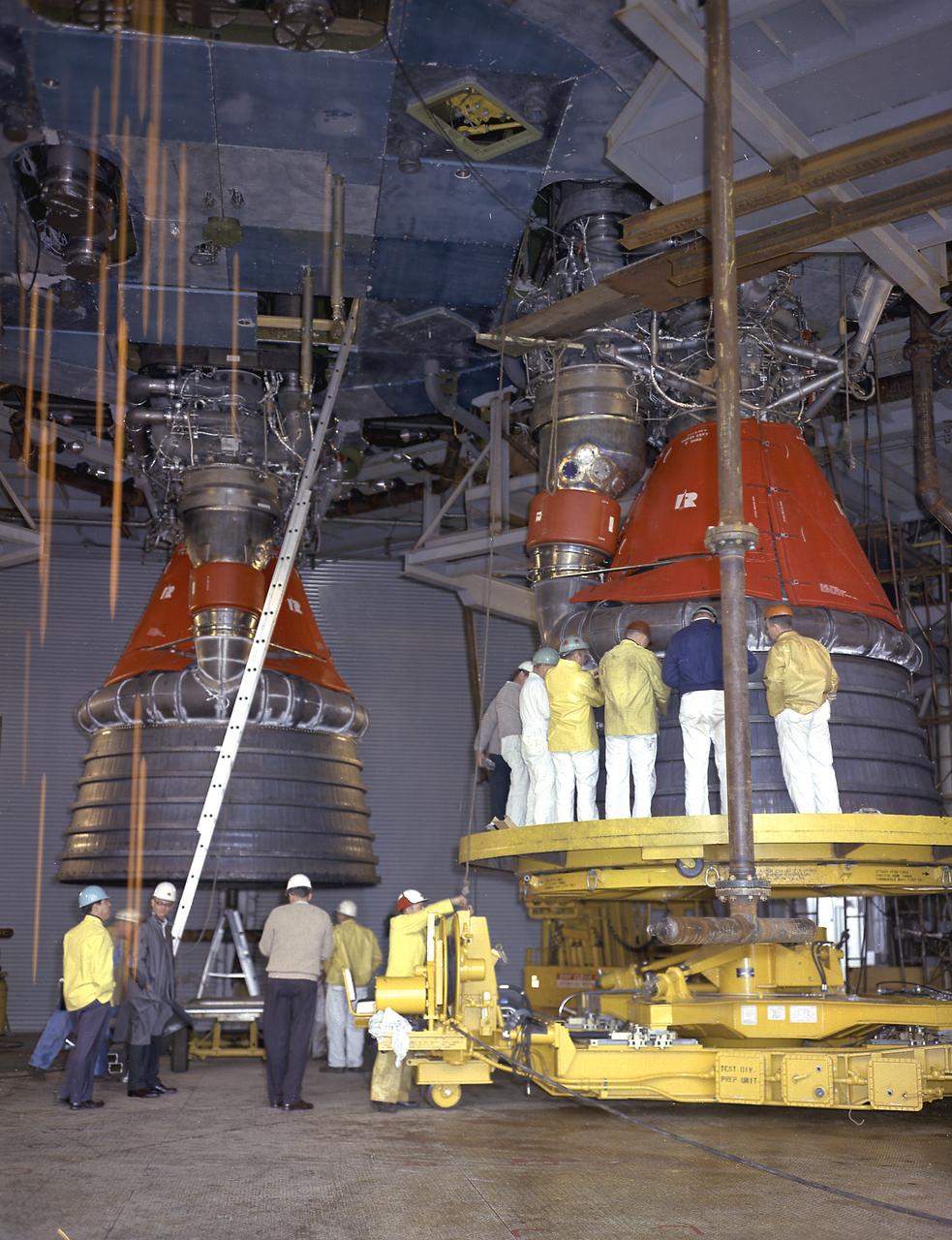
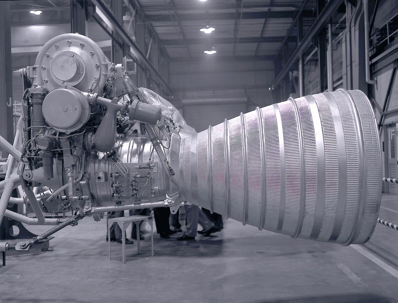
CLOSE-UP OF H-1 ENGINE INSTALLED ON SATURN S-1B STAGE (SA-T) NEAR PROPULSION AND STRUCTURAL TEST FACILITY (BUILDING 4572) AT THE GEORGE C. MARSHALL SPACE FLIGHT CENTER.
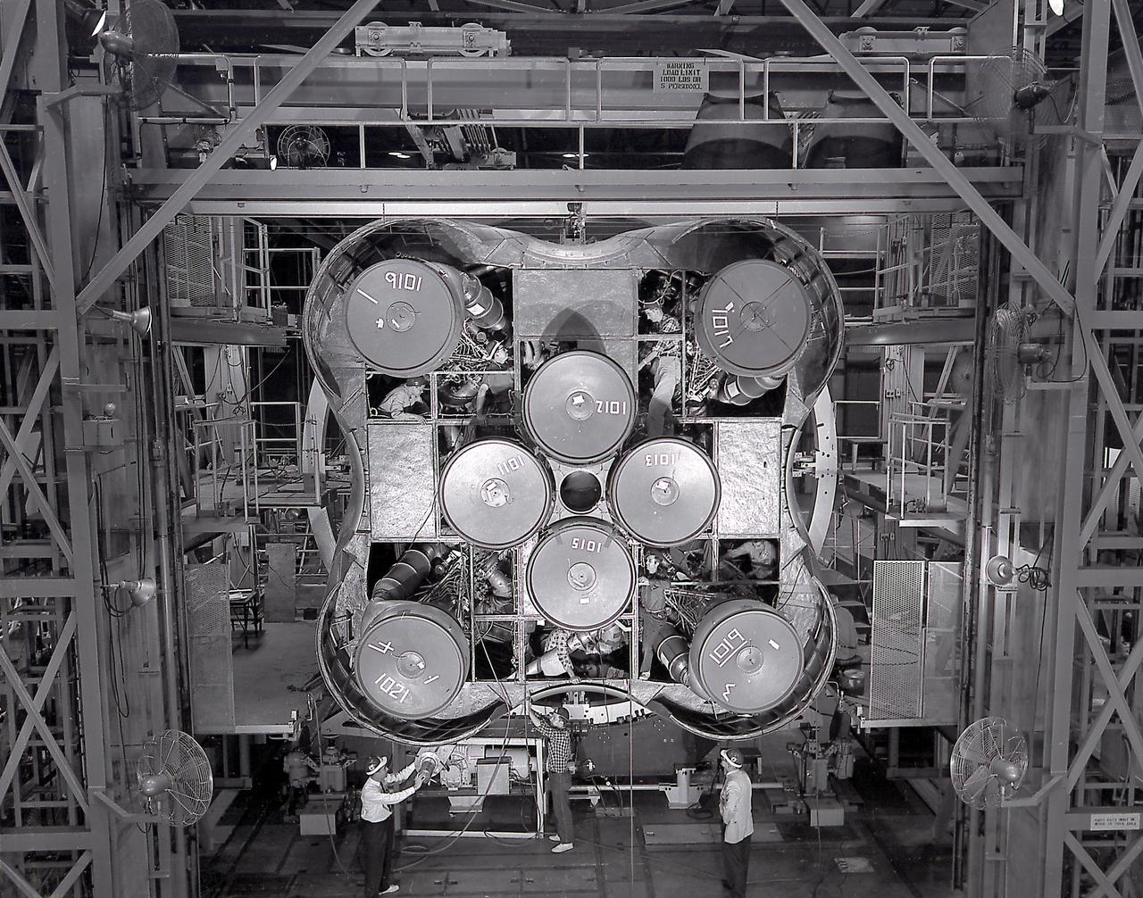
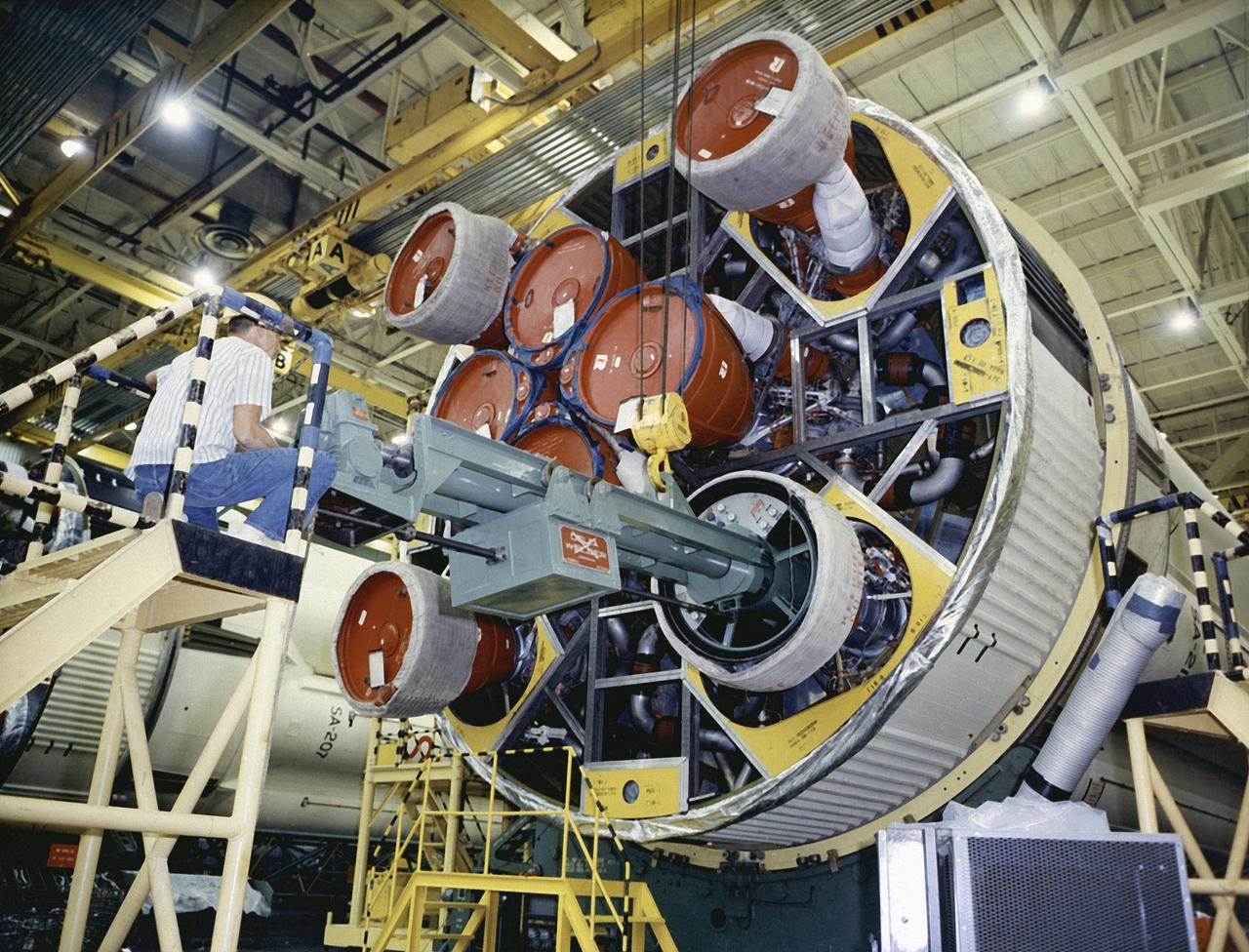
The Saturn I S-I stage with eight H-1 engines, located in Marshall Space Flight Center building 4705, showing the positioning of eight H-1 engines. The Saturn I S-I stage had eight H-1 engines clustered, using liquid oxygen/kerosene-1 (LOX/RP-1) propellants capable of producing a total of 1,500,000 pounds of thrust.
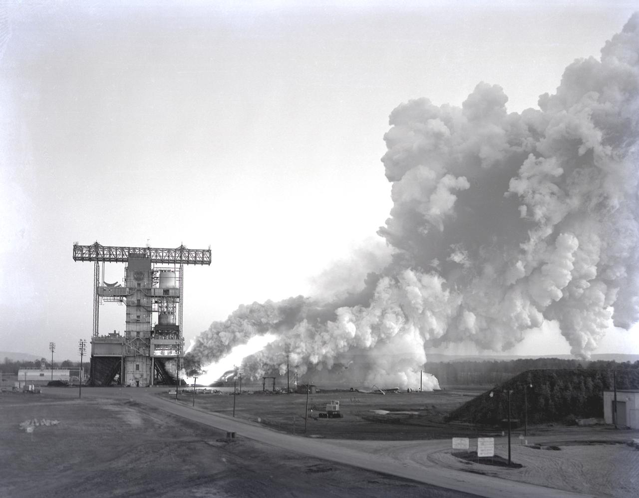
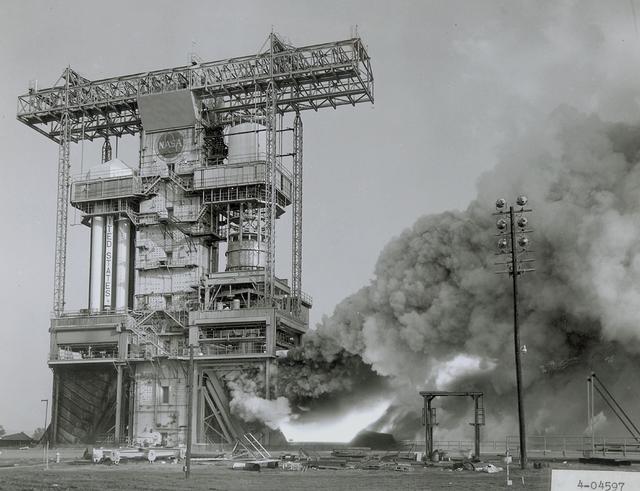
The test laboratory of the Marshall Space Flight Center (MSFC) tested the F-1 engine, the most powerful rocket engine ever fired at MSFC. The engine was tested on the newly modified Saturn IB Static Test Stand which had been used for three years to test the Saturn I eight-engine booster, S-I (first) stage. In 1961 the test stand was modified to permit static firing of the S-I/S-IB stage and the name of the stand was then changed to the S-IB Static Test Stand. Producing a combined thrust of 7,500,000 pounds, five F-1 engines powered the S-IC (first) stage of the Saturn V vehicle for the marned lunar mission.
The test laboratory of the Marshall Space Flight Center (MSFC) tested the F-1 engine, the most powerful rocket engine ever fired at MSFC. The engine was tested on the newly modified Saturn IB static test stand that had been used for three years to test the Saturn I eight-engine booster, S-I (first) stage. In 1961, the test stand was modified to permit static firing of the S-I/S-IB stage and the name of the stand was then changed to the S-IB Static Test Stand. Producing a combined thrust of 7,500,000 pounds, five F-1 engines powered the S-IC (first) stage of the Saturn V vehicle for the marned lunar mission.
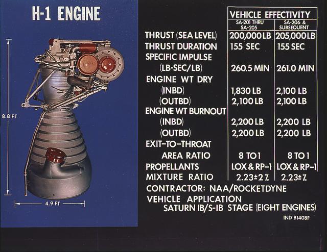
H-1 engine characteristics: The H-1 engine was developed under the management of the Marshall Space Flight Center (MSFC). The cluster of eight H-1 engines was used to power the first stage of the Saturn I (S-I stage) and Saturn IB (S-IVB stage) launch vehicles, and produced 188,00 pounds of thrust, a combined thrust of 1,500,000 pounds, later uprated to 205,000 pounds of thrust and a combined total thrust of 1,650,000 pounds for the Saturn IB program.
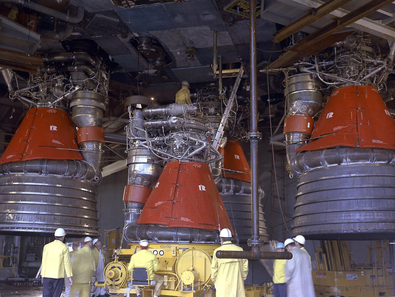
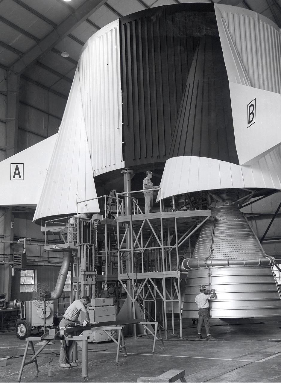
Engineers at the Marshall Space Flight Center install the F-1 engines on the S-IC stage thrust structure at the S-IC static test stand. Engines are installed on the stage after it has been placed in the test stand. This image shows a close-up of an F-1 engine. Five F-1 engines, each weighing 10 tons, gave the booster a total thrust of 7,500,000 pounds, roughly equivalent to 160 million horsepower.
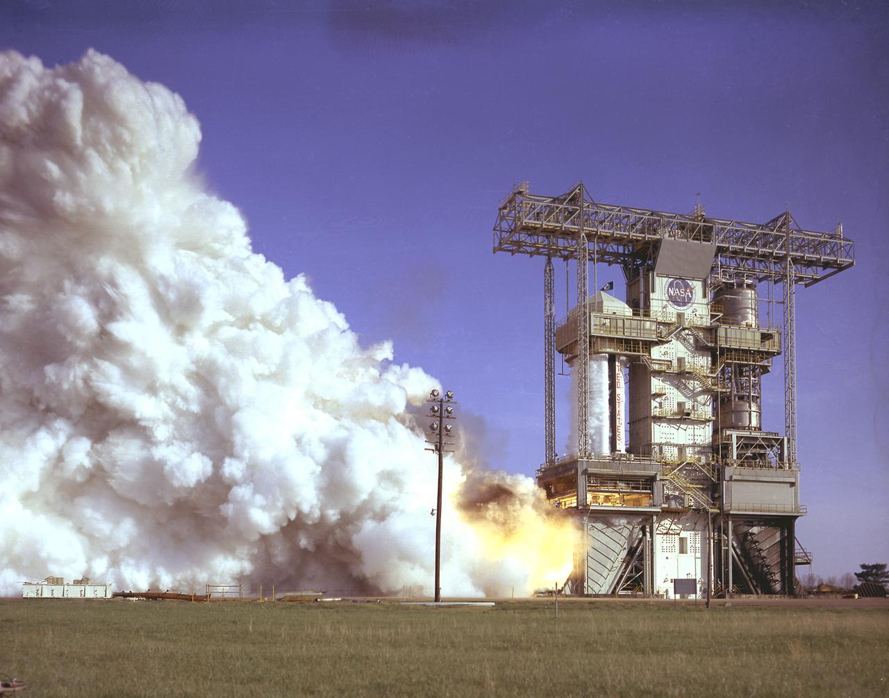
S-IB-1, the first flight version of the Saturn IB launch vehicle's first stage (S-IB stage), undergoes a full-duration static firing in Saturn IB static test stand at the Marshall Space Flight Center (MSFC) on April 13, 1965. Developed by the MSFC and built by the Chrysler Corporation at the Michoud Assembly Facility (MAF) in New Orleans, Louisiana, the 90,000-pound booster utilized eight H-1 engines to produce a combined thrust of 1,600,000 pounds. Between April 1965 and July 1968, MSFC performed thirty-two static tests on twelve different S-IB stages.
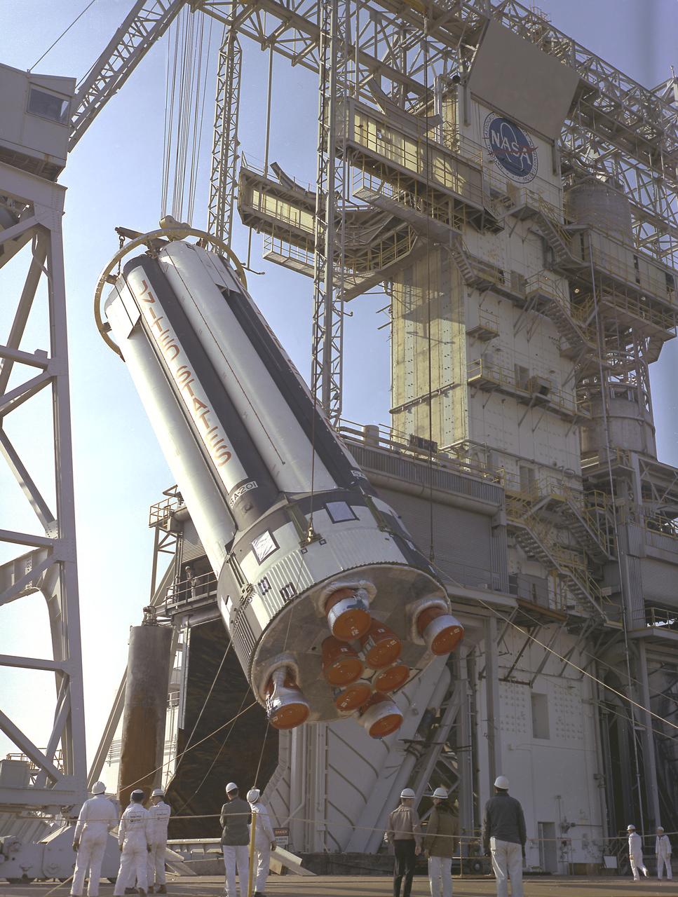
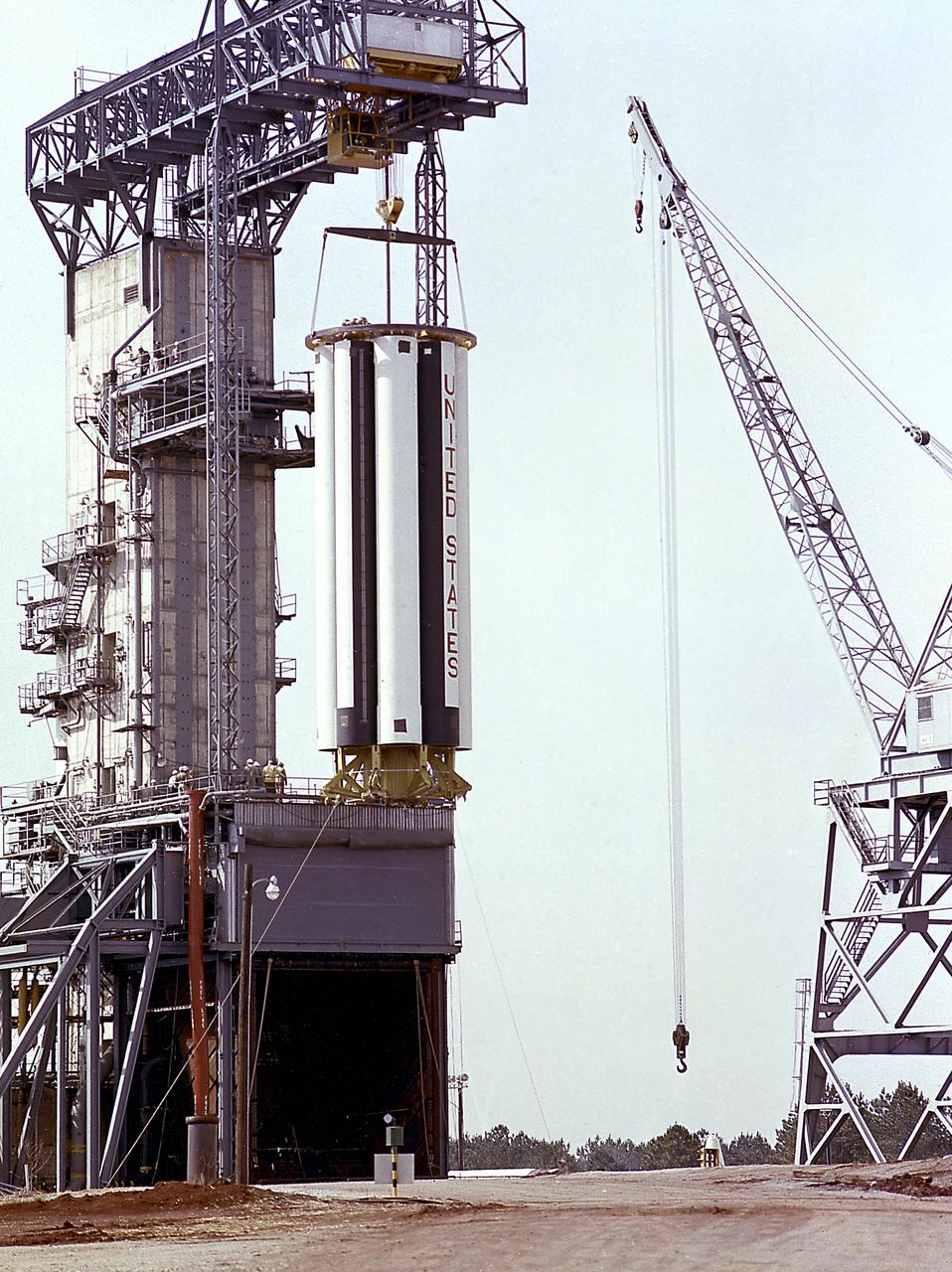
Workers at the Marshall Space Flight Center (MSFC) hoist S-IB-1, the first flight version of the Saturn IB launch vehicle's first stage (S-IB stage), into the Saturn IB static test stand on March 15, 1965. Developed by the MSFC and built by the Chrysler Corporation at the Michoud Assembly Facility (MAF) in New Orleans, Louisiana, the 90,000-pound booster utilized eight H-1 engines to produce a combined thrust of 1,600,000 pounds.
S-IB-1, the first flight version of the Saturn IB launch vehicle's first stage (S-IB stage), sat in the Marshall Space Flight Center (MSFC) Saturn IB static test stand on March 15, 1965. Developed by the MSFC and built by the Chrysler Corporation at the Michoud Assembly Facility (MAF) in New Orleans, Louisiana, the 90,000-pound booster utilized eight H-1 engines to produce a combined thrust of 1,600,000 pounds.
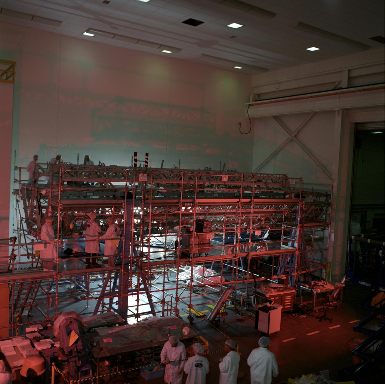
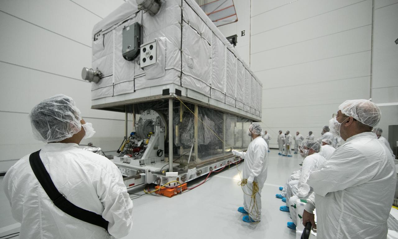
This image shows the Integrated Truss Assembly S-1 (S-One), the Starboard Side Thermal Radiator Truss, for the International Space Station (ISS) undergoing final construction in the Space Station manufacturing facility at the Marshall Space Flight Center. The S1 truss provides structural support for the orbiting research facility's radiator panels, which use ammonia to cool the Station's complex power system. Delivered and installed by the STS-112 mission, the S1 truss, attached to the S0 (S Zero) truss installed by the previous STS-110 mission, flows 637 pounds of anhydrous ammonia through three heat rejection radiators. The truss is 45-feet long, 15-feet wide, 10-feet tall, and weighs approximately 32,000 pounds. Manufactured by the Boeing Company in Huntington Beach, California, the truss primary structure was transferred to the Marshall Space Flight Center in February 1999 for hardware installations and manufacturing acceptance testing.
Engineers and technicians at the Marshall Space Flight Center were installing an F-I engine on the Saturn V S-IC (first) stage thrust structure in building 4705. The S-IC (first) stage used five F-1 engines that produced a total thrust of 7,500,000 pounds as each engine produced 1,500,000 pounds of thrust. The S-IC stage lifted the Saturn V vehicle and Apollo spacecraft from the launch pad.
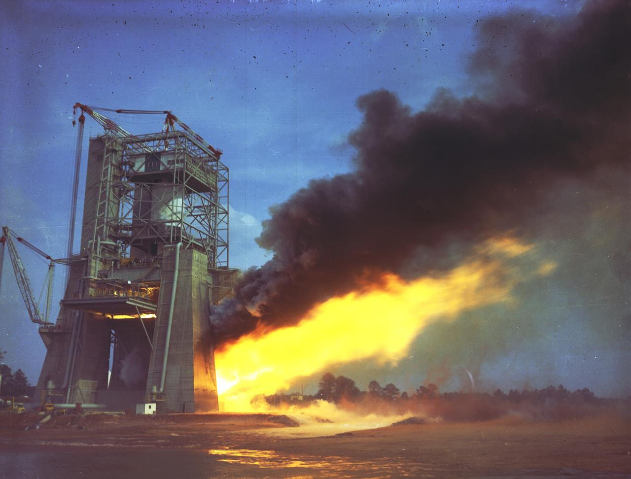
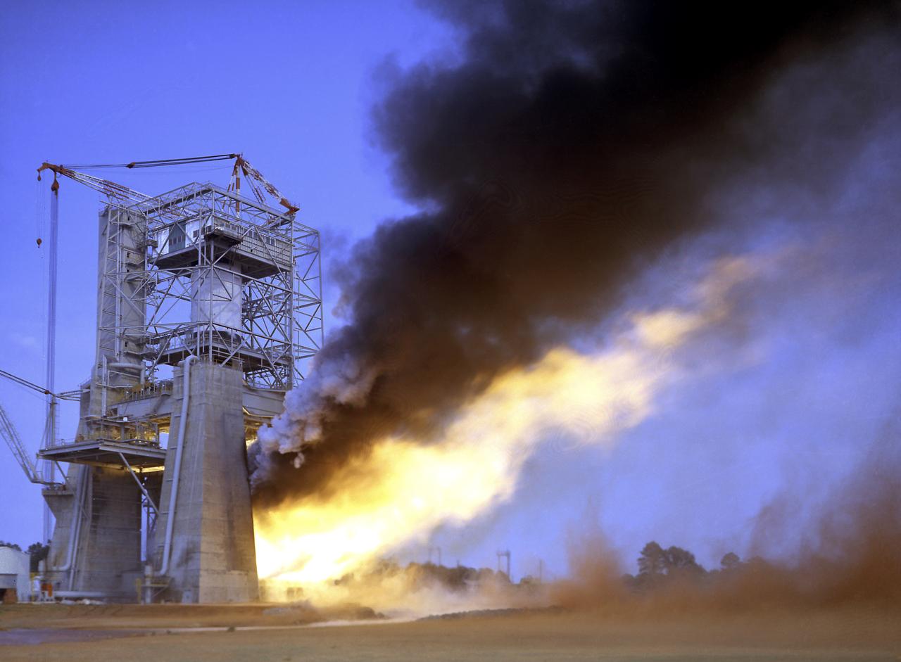
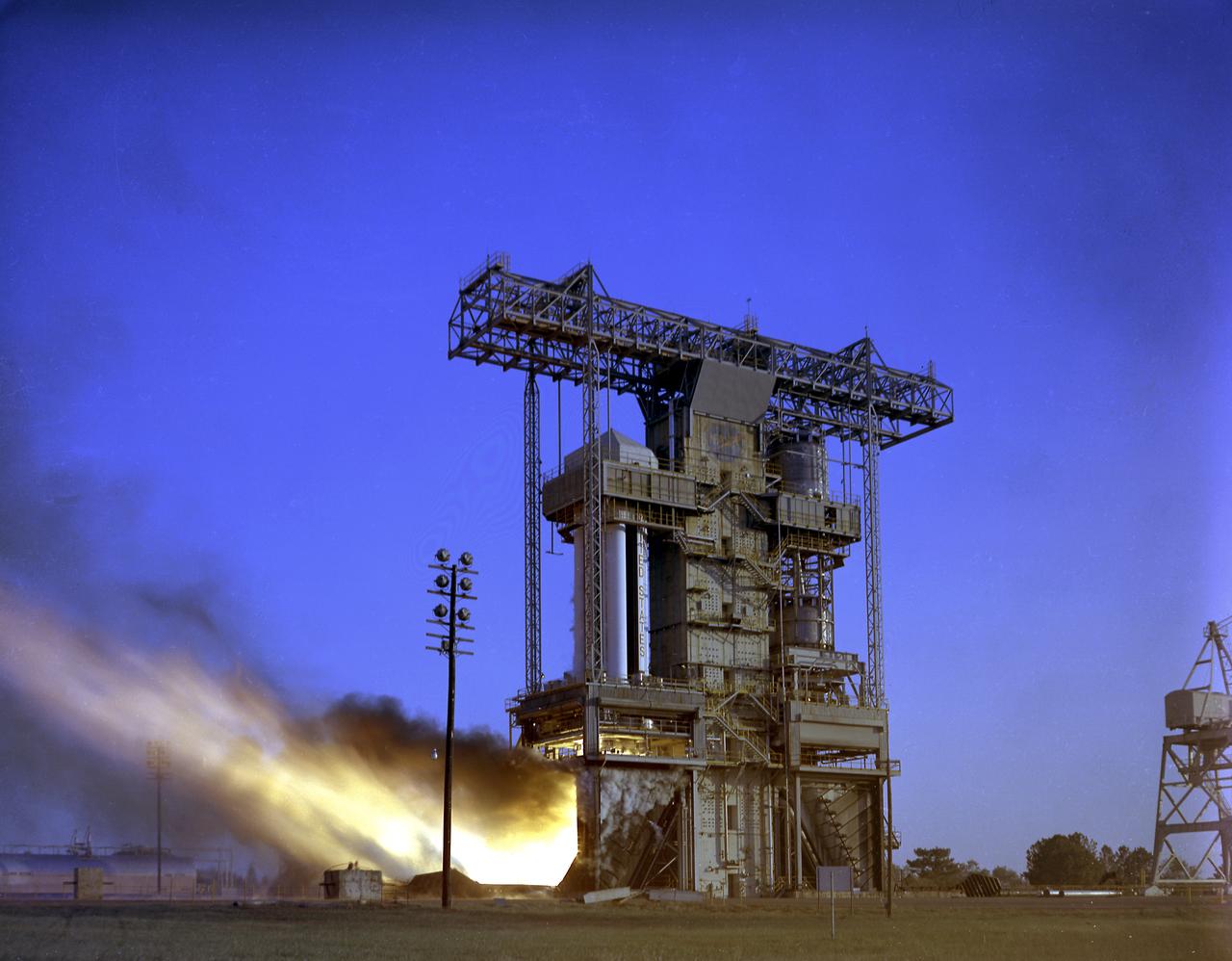
The Saturn V first stages were test fired at the Mississippi Test Facility and at the Marshall Space Flight Center (MSFC). Five F-1 engines powered the first stage, each developing 1.5 million pounds of thrust. The first stage, known as the S-IC stage, burned over 15 tons of propellant per second during its 2.5 minutes of operation to take the vehicle to a height of about 36 miles and to a speed of about 6,000 miles per hour. The stage was 138 feet long and 33 feet in diameter. This photograph shows the test firing of an F-1 engine at the MSFC's S-IC Static Test Firing Facility.
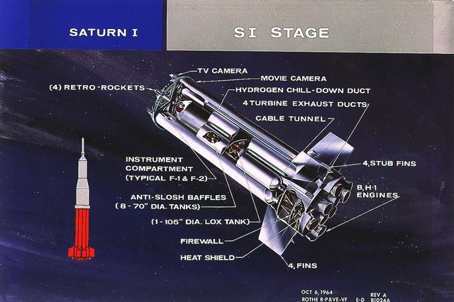
This cutaway illustrates the S-I stage, the first stage of the Saturn I vehicle developed by the Marshall Space Flight Center (MSFC). The stage was propelled by a cluster of eight H-1 engines, capable of producing 1,500,000 pounds of thrust.
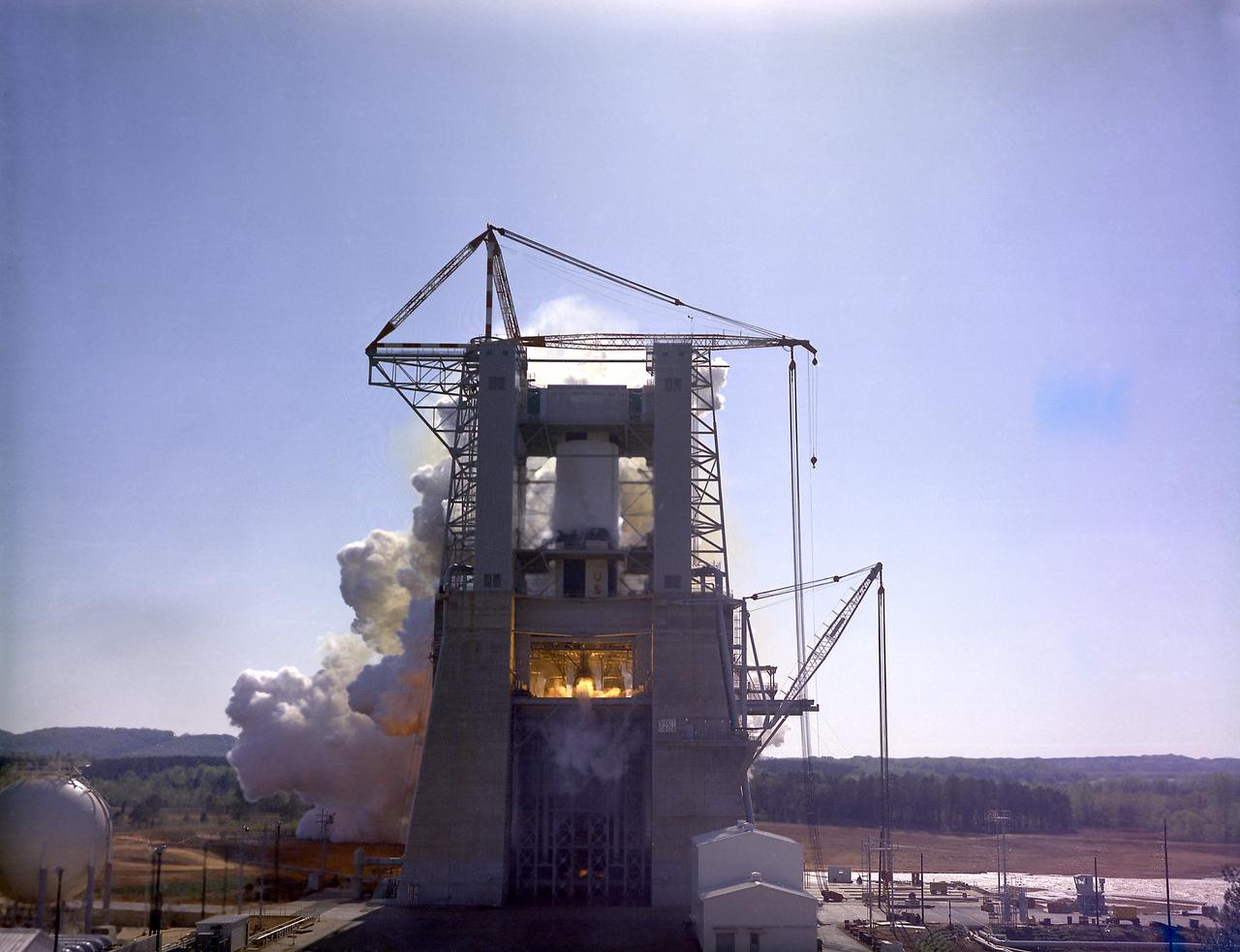
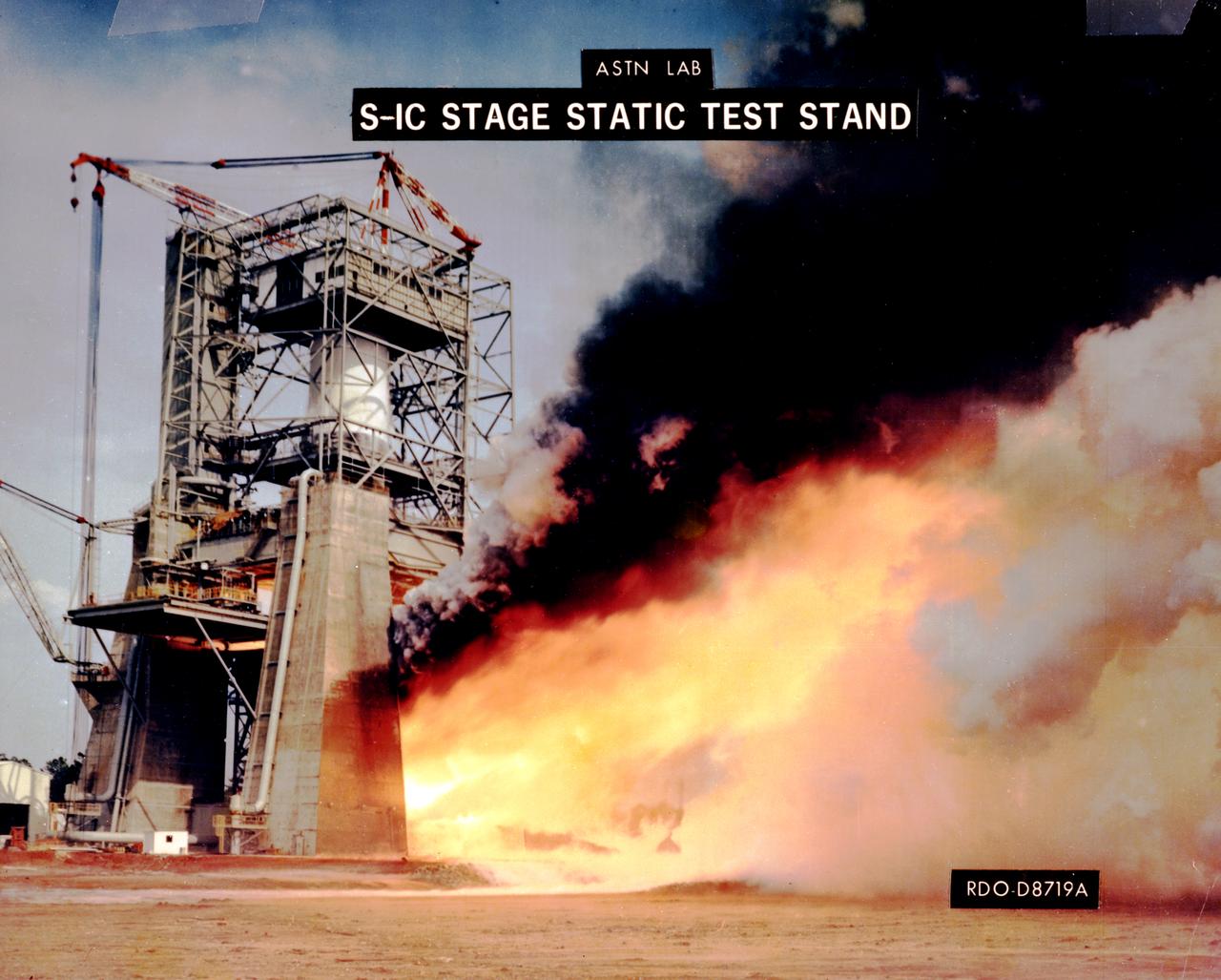
The flame and exhaust from the test firing of an F-1 engine blast out from the Saturn S-IB Static Test Stand in the east test area of the Marshall Space Flight Center. A Cluster of five F-1 engines, located in the S-IC (first) stage of the Saturn V vehicle, provided over 7,500,000 pounds of thrust to launch the giant rocket. The towering 363-foot Saturn V was a multistage, multiengine launch vehicle standing taller than the Statue of Liberty. Altogether, the Saturn V engines produced as much power as 85 Hoover Dams.
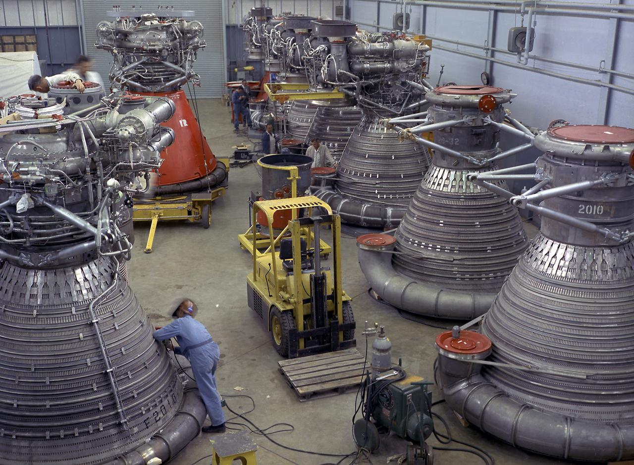
This photograph shows F-1 engines being stored in the F-1 Engine Preparation Shop, building 4666, at the Marshall Space Flight Center. Each F-1 engine produced a thrust of 1,500,000 pounds. A cluster of five engines was mounted on the thrust structure of the S-IC stage of a 364-foot long Saturn V launch vehicle that ultimately took astronauts to the Moon.
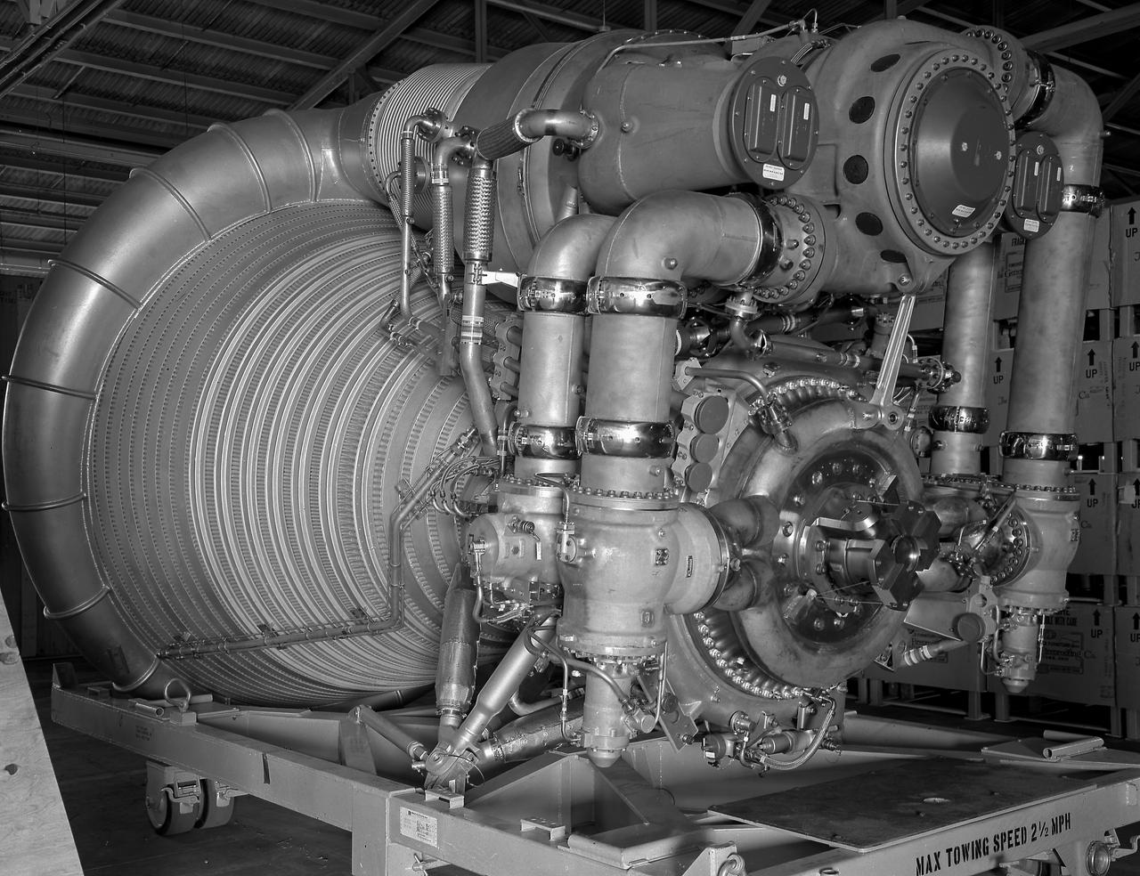
A close-up view of the F-1 Engine for the Saturn V S-IC (first) stage depicts the complexity of the engine. Developed by Rocketdyne under the direction of the Marshall Space Flight Center, the F-1 engine was utilized in a cluster of five engines to propel the Saturn V's first stage, the S-IC. Liquid oxygen and kerosene were used as its propellant. Initially rated at 1,500,000 pounds of thrust, the engine was later uprated to 1,522,000 pounds of thrust after the third Saturn V launch (Apollo 8, the first marned Saturn V mission) in December 1968. The cluster of five F-1 engines burned over 15 tons of propellant per second, during its two and one-half minutes of operation, to take the vehicle to a height of about 36 miles and to a speed of about 6,000 miles per hour.
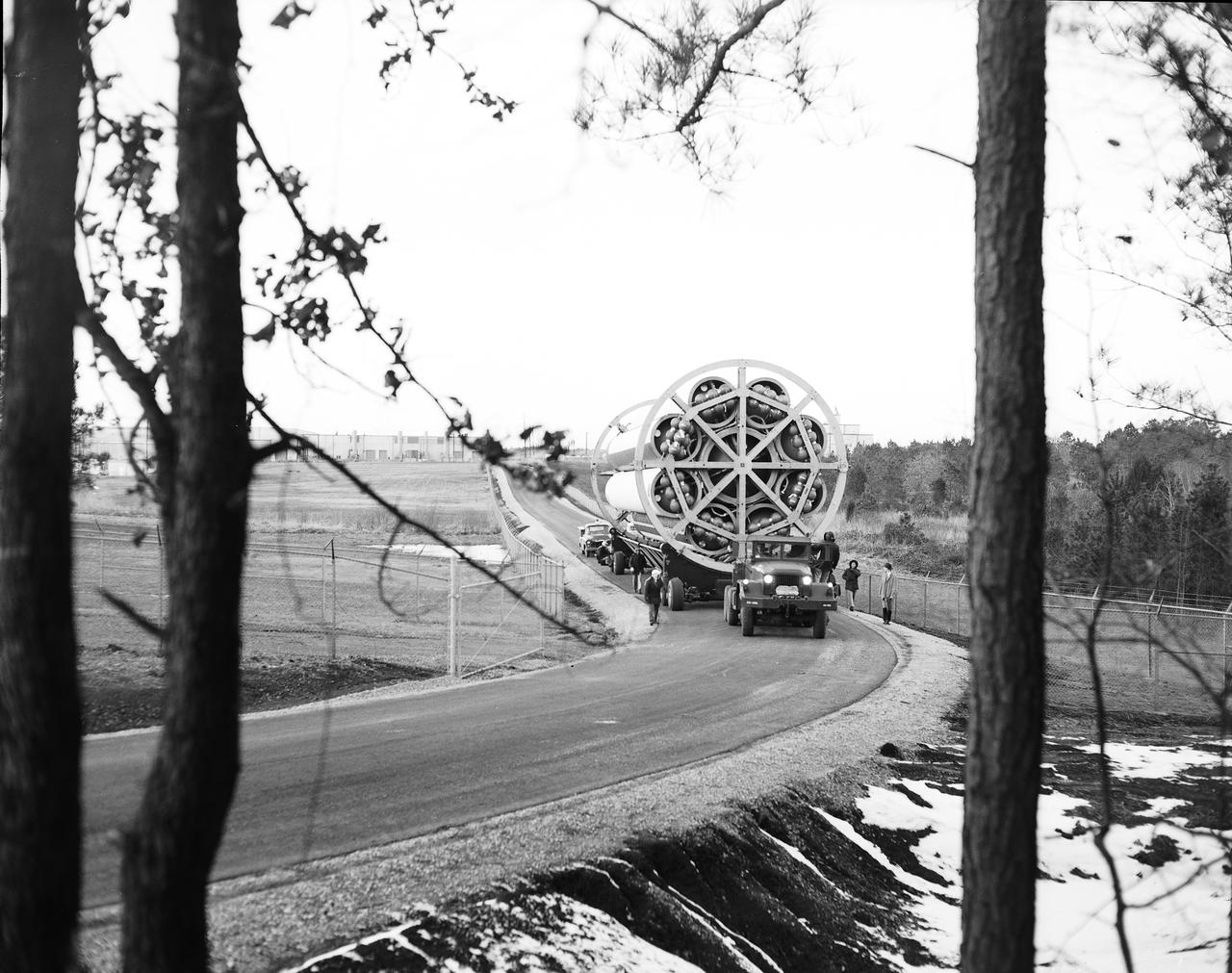
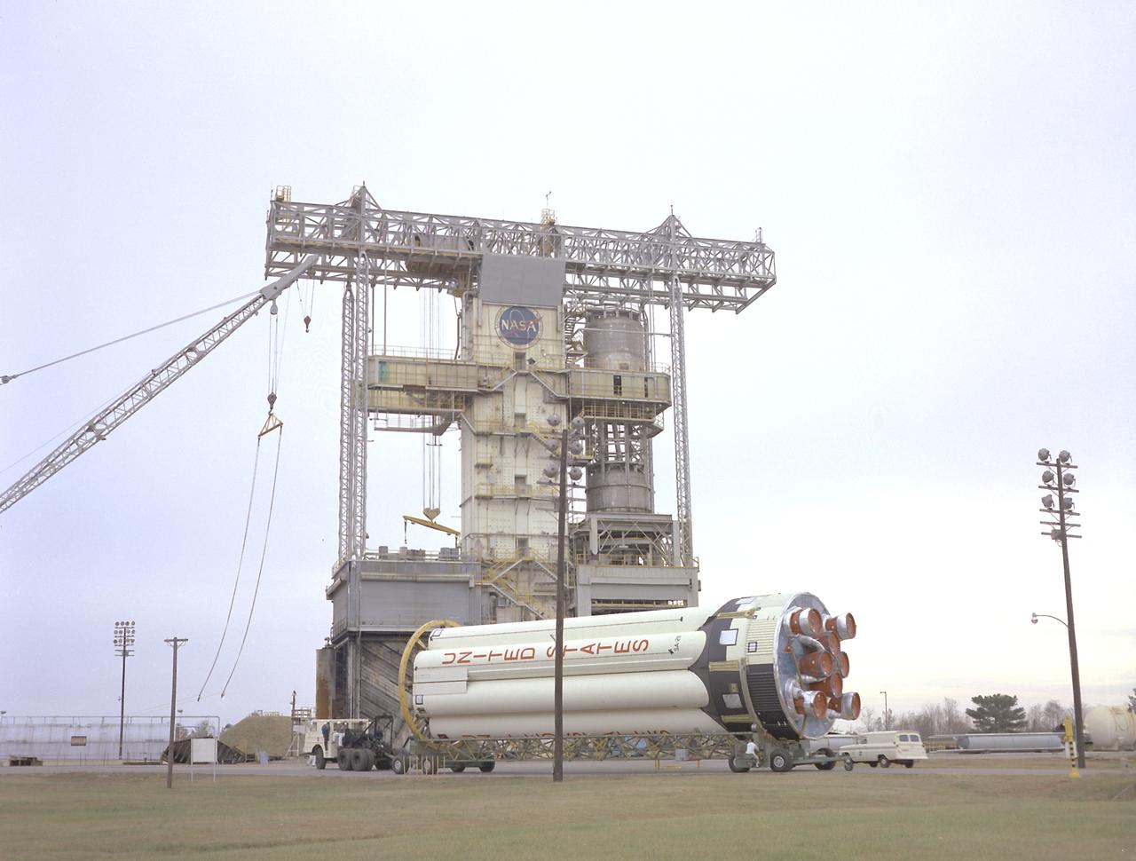
This photograph shows the Saturn-I first stage (S-1 stage) being transported to the test stand for a static test firing at the Marshall Space Flight Center. Soon after NASA began operations in October 1958, it was evident that sending people and substantial equipment beyond the Earth's gravitational field would require launch vehicles with weight-lifting capabilities far beyond any developed to that time. In early 1959, NASA accepted the proposal of Dr. Wernher von Braun for a multistage rocket, with a number of engines clustered in one or more of the stages to provide a large total thrust. The initiation of the Saturn launch vehicle program ultimately led to the study and preliminary plarning of many different configurations and resulted in production of three Saturn launch vehicles, the Saturn-I, Saturn I-B, and Saturn V. The Saturn family of launch vehicles began with the Saturn-I, a two-stage vehicle originally designated C-1. The research and development program was planned in two phases, or blocks: one for first stage development (Block I) and the second for both first and second stage development (Block-II). Saturn I had a low-earth-orbit payload capability of approximately 25,000 pounds. The design of the first stage (S-1 stage) used a cluster of propellant tanks containing liquid oxygen (LOX) and kerosene (RP-1), and eight H-1 engines, yielding a total thrust of 1,500,000 pounds. Of the ten Saturn-Is planned, the first eight were designed and built at the Marshall Space Flight Center, and the remaining two were built by the Chrysler Corporation.
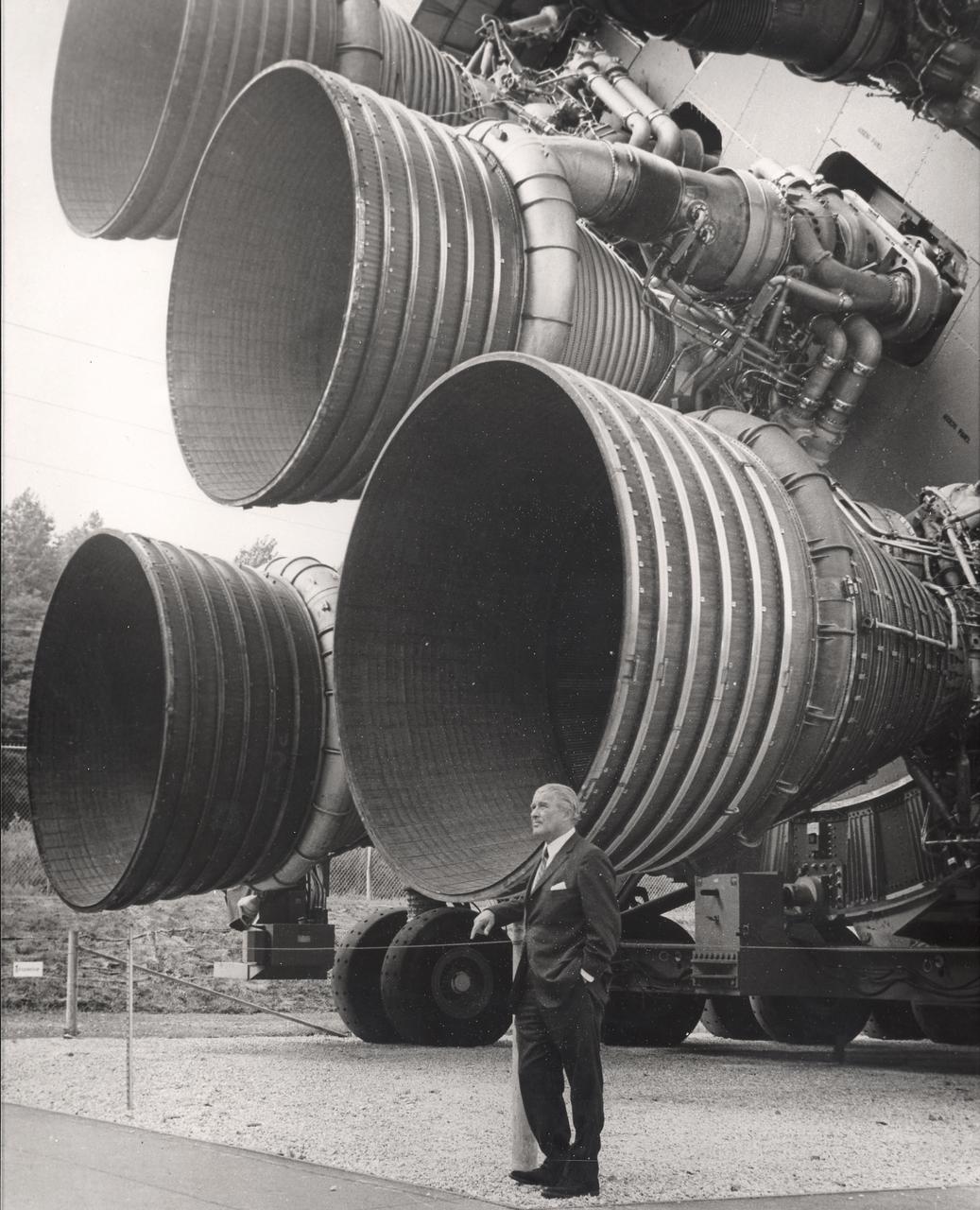
A pioneer of America's space program, Dr. von Braun stands by the five F-1 engines of the Saturn V launch vehicle. This Saturn V vehicle is an actual test vehicle which has been displayed at the U.S. Space Rocket Center in Huntsville, Alabama. Designed and developed by Rocketdyne under the direction of the Marshall Space Flight Center, a cluster of five F-1 engines was mounted on the Saturn V S-IC (first) stage. The engines measured 19-feet tall by 12.5-feet at the nozzle exit and burned 15 tons of liquid oxygen and kerosene each second to produce 7,500,000 pounds of thrust. The S-IC stage is the first stage, or booster, of a 364-foot long rocket that ultimately took astronauts to the Moon.
Workers at the Michoud Assembly Facility (MAF) near New Orleans, Louisiana, install the last engine on the S-IB stage. Developed by the Marshall Space Flight Center (MSFC) and built by the Chrysler Corporation at MAF, the S-IB stage utilized eight H-1 engines to produce a combined thrust of 1,600,000 pounds.
Engineers at the Marshall Space Flight Center install the F-1 engines on the S-IC stage thrust structure at the S-IC static test stand. Engines are installed on the stage after it has been placed in the test stand. Five F-1 engines, each weighing 10 tons, gave the booster a total thrust of 7,500,000 pounds, roughly equivalent to 160 million horsepower.
Engineers at the Marshall Space Flight Center install the F-1 engines on the S-IC stage thrust structure at the S-IC static test stand. Engines are installed on the stage after it has been placed in the test stand. Five F-1 engines, each weighing 10 tons, gave the booster a total thrust of 7,500,000 pounds, roughly equivalent to 160 million horsepower.
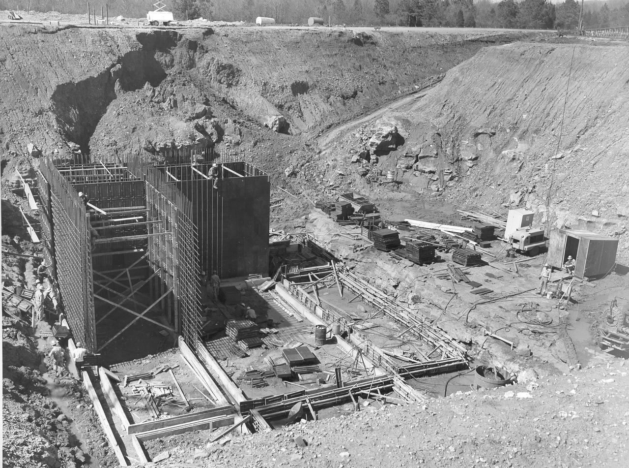
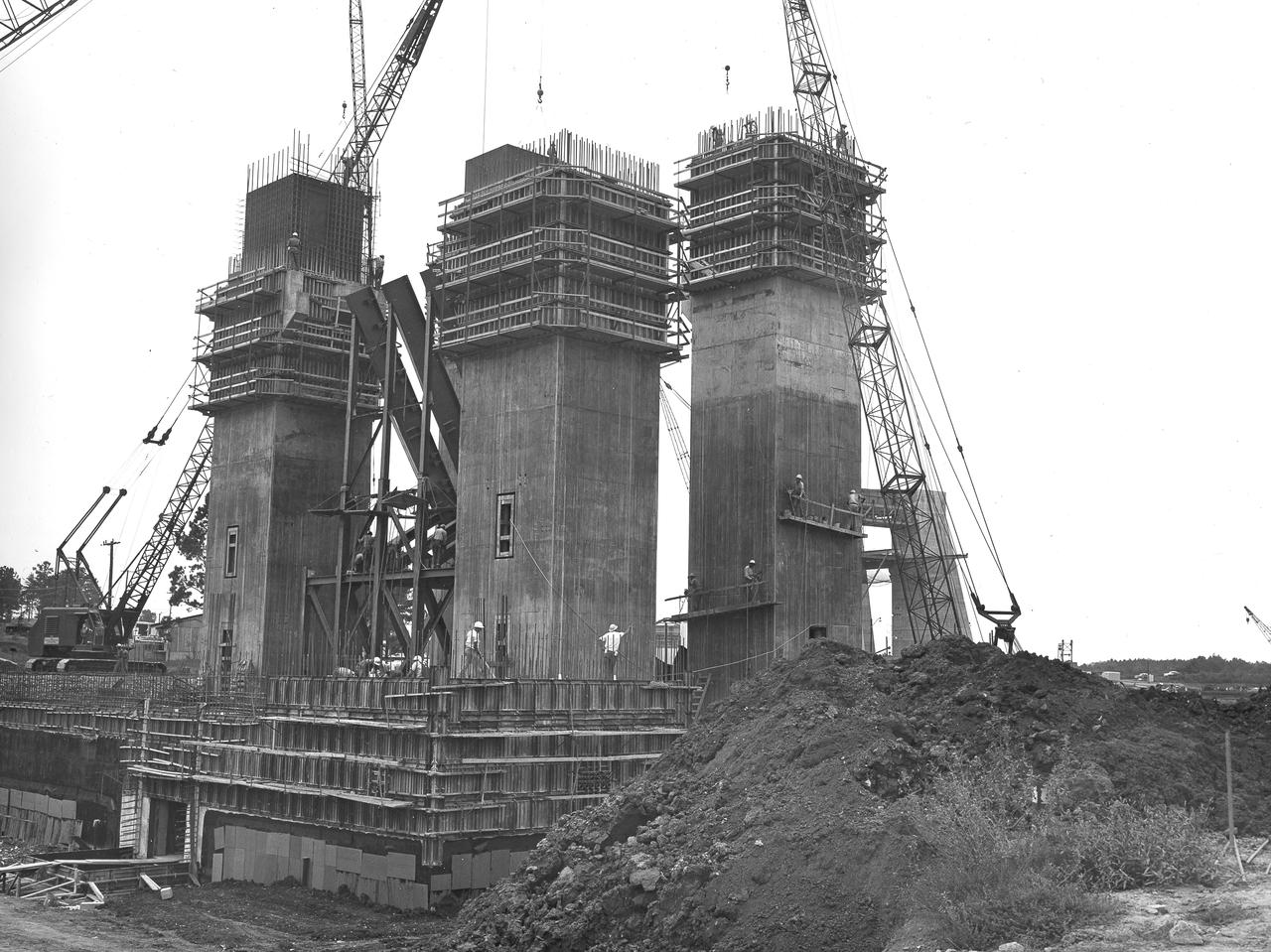
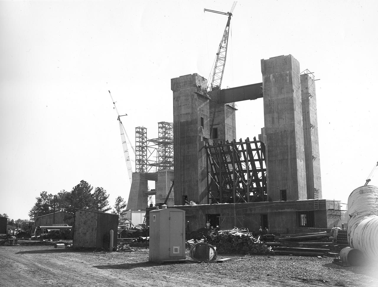
At its founding, the Marshall Space Flight Center (MSFC) inherited the Army’s Jupiter and Redstone test stands, but much larger facilities were needed for the giant stages of the Saturn V. From 1960 to 1964, the existing stands were remodeled and a sizable new test area was developed. The new comprehensive test complex for propulsion and structural dynamics was unique within the nation and the free world, and they remain so today because they were constructed with foresight to meet the future as well as on going needs. Construction of the S-IC Static test stand complex began in 1961 in the west test area of MSFC, and was completed in 1964. The S-IC static test stand was designed to develop and test the 138-ft long and 33-ft diameter Saturn V S-IC first stage, or booster stage, weighing in at 280,000 pounds. Required to hold down the brute force of a 7,500,000-pound thrust produced by 5 F-1 engines, the S-IC static test stand was designed and constructed with the strength of hundreds of tons of steel and 12,000,000 pounds of cement, planted down to bedrock 40 feet below ground level. The foundation walls, constructed with concrete and steel, are 4 feet thick. The base structure consists of four towers with 40-foot-thick walls extending upward 144 feet above ground level. The structure was topped by a crane with a 135-foot boom. With the boom in the upright position, the stand was given an overall height of 405 feet, placing it among the highest structures in Alabama at the time. North of the massive S-IC test stand, the F-1 Engine test stand was built. Designed to assist in the development of the F-1 Engine, the F-1 test stand is a vertical engine firing test stand, 239 feet in elevation and 4,600 square feet in area at the base. Capability was provided for static firing of 1.5 million pounds of thrust using liquid oxygen and kerosene. Like the S-IC stand, the foundation of the F-1 stand is keyed into the bedrock approximately 40 feet below grade. This photo, taken April 4, 1963 depicts the construction of the F-1 test stand foundation walls.
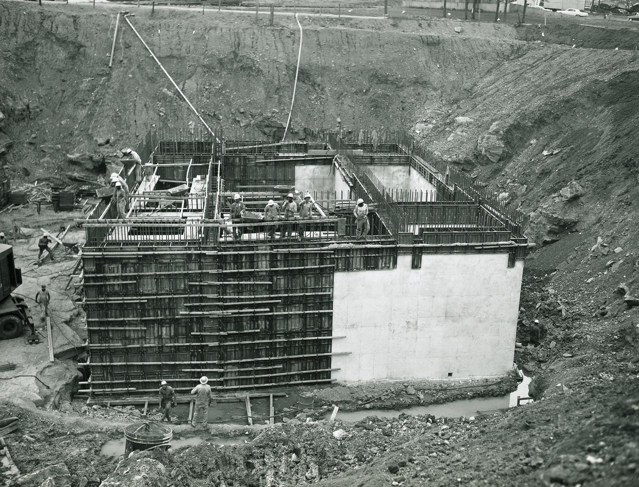
At its founding, the Marshall Space Flight Center (MSFC) inherited the Army’s Jupiter and Redstone test stands, but much larger facilities were needed for the giant stages of the Saturn V. From 1960 to 1964, the existing stands were remodeled and a sizable new test area was developed. The new comprehensive test complex for propulsion and structural dynamics was unique within the nation and the free world, and they remain so today because they were constructed with foresight to meet the future as well as on going needs. Construction of the S-IC Static test stand complex began in 1961 in the west test area of MSFC, and was completed in 1964. The S-IC static test stand was designed to develop and test the 138-ft long and 33-ft diameter Saturn V S-IC first stage, or booster stage, weighing in at 280,000 pounds. Required to hold down the brute force of a 7,500,000-pound thrust produced by 5 F-1 engines, the S-IC static test stand was designed and constructed with the strength of hundreds of tons of steel and 12,000,000 pounds of cement, planted down to bedrock 40 feet below ground level. The foundation walls, constructed with concrete and steel, are 4 feet thick. The base structure consists of four towers with 40-foot-thick walls extending upward 144 feet above ground level. The structure was topped by a crane with a 135-foot boom. With the boom in the upright position, the stand was given an overall height of 405 feet, placing it among the highest structures in Alabama at the time. North of the massive S-IC test stand, the F-1 Engine test stand was built. Designed to assist in the development of the F-1 Engine, the F-1 test stand is a vertical engine firing test stand, 239 feet in elevation and 4,600 square feet in area at the base. Capability was provided for static firing of 1.5 million pounds of thrust using liquid oxygen and kerosene. Like the S-IC stand, the foundation of the F-1 stand is keyed into the bedrock approximately 40 feet below grade. This photo, taken April 17, 1963 depicts the construction of the F-1 test stand foundation walls.
At its founding, the Marshall Space Flight Center (MSFC) inherited the Army’s Jupiter and Redstone test stands, but much larger facilities were needed for the giant stages of the Saturn V. From 1960 to 1964, the existing stands were remodeled and a sizable new test area was developed. The new comprehensive test complex for propulsion and structural dynamics was unique within the nation and the free world, and they remain so today because they were constructed with foresight to meet the future as well as on going needs. Construction of the S-IC Static test stand complex began in 1961 in the west test area of MSFC, and was completed in 1964. The S-IC static test stand was designed to develop and test the 138-ft long and 33-ft diameter Saturn V S-IC first stage, or booster stage, weighing in at 280,000 pounds. Required to hold down the brute force of a 7,500,000-pound thrust produced by 5 F-1 engines, the S-IC static test stand was designed and constructed with the strength of hundreds of tons of steel and 12,000,000 pounds of cement, planted down to bedrock 40 feet below ground level. The foundation walls, constructed with concrete and steel, are 4 feet thick. The base structure consists of four towers with 40-foot-thick walls extending upward 144 feet above ground level. The structure was topped by a crane with a 135-foot boom. With the boom in the upright position, the stand was given an overall height of 405 feet, placing it among the highest structures in Alabama at the time. North of the massive S-IC test stand, the F-1 Engine test stand was built. Designed to assist in the development of the F-1 Engine, the F-1 test stand is a vertical engine firing test stand, 239 feet in elevation and 4,600 square feet in area at the base. Capability was provided for static firing of 1.5 million pounds of thrust using liquid oxygen and kerosene. Like the S-IC stand, the foundation of the F-1 stand is keyed into the bedrock approximately 40 feet below grade. This photo, taken April 4, 1963 depicts the construction of the F-1 test stand foundation walls.
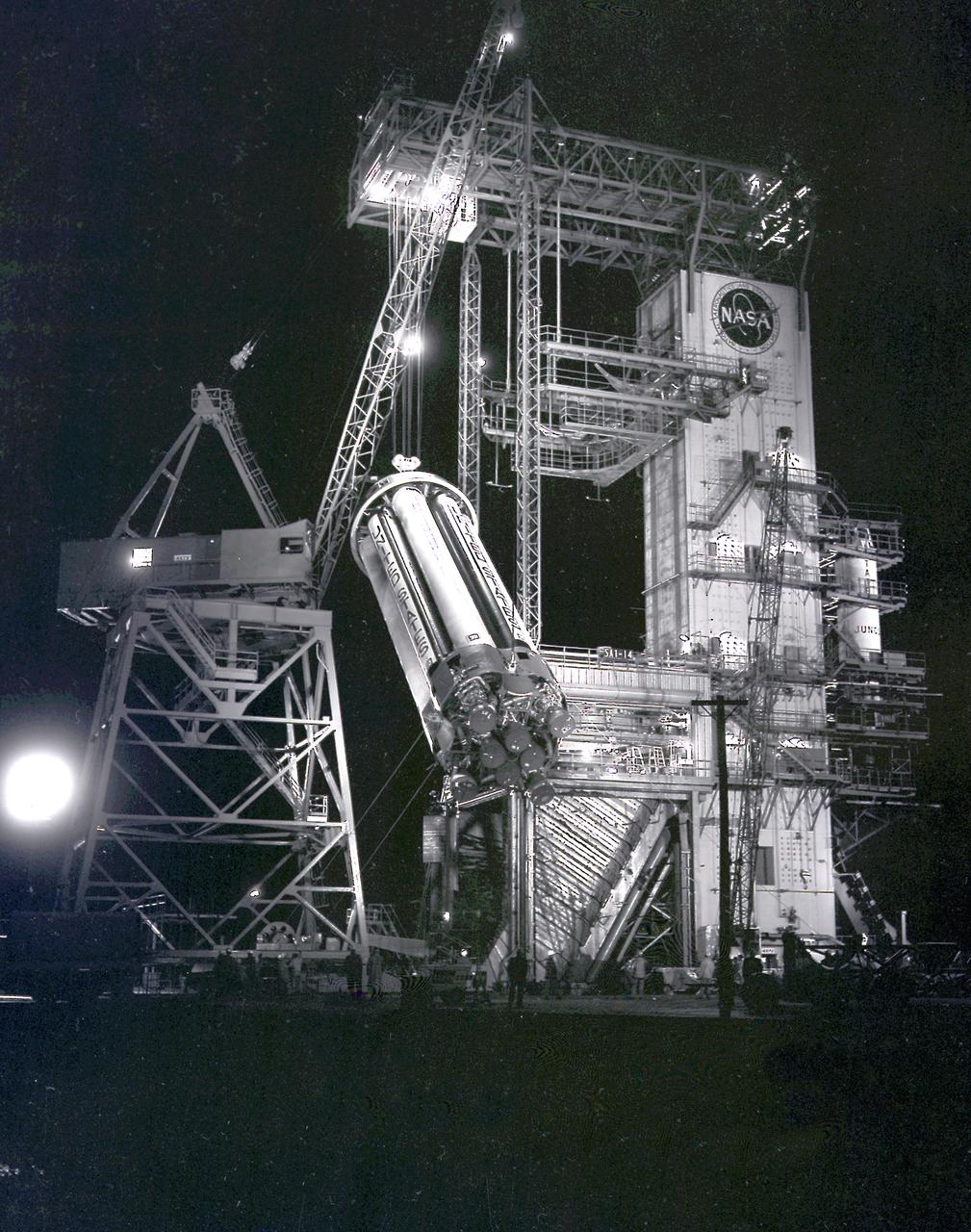
This night photograph depicts the SA-1 booster (Saturn I S-I stage) being removed from the test stand after the first flight qualification testing at the Marshall Space Flight Center (MSFC).
This photograph depicts a dramatic view of the first test firing of all five F-1 engines for the Saturn V S-IC stage at the Marshall Space Flight Center. The testing lasted a full duration of 6.5 seconds. It also marked the first test performed in the new S-IC static test stand and the first test using the new control blockhouse. The S-IC stage is the first stage, or booster, of a 364-foot long rocket that ultimately took astronauts to the Moon. Operating at maximum power, all five of the engines produced 7,500,000 pounds of thrust. Required to hold down the brute force of a 7,500,000-pound thrust, the S-IC static test stand was designed and constructed with the strength of hundreds of tons of steel and cement, planted down to bedrock 40 feet below ground level. The structure was topped by a crane with a 135-foot boom. With the boom in the up position, the stand was given an overall height of 405 feet, placing it among the highest structures in Alabama at the time. When the Saturn V S-IC first stage was placed upright in the stand , the five F-1 engine nozzles pointed downward on a 1,900 ton, water-cooled deflector. To prevent melting damage, water was sprayed through small holes in the deflector at the rate 320,000 gallons per minute.
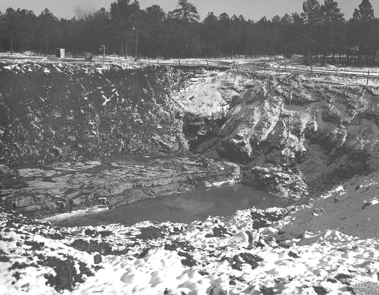
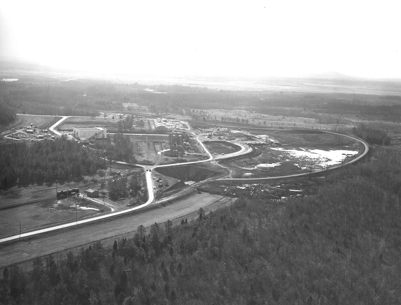
At its founding, the Marshall Space Flight Center (MSFC) inherited the Army’s Jupiter and Redstone test stands, but much larger facilities were needed for the giant stages of the Saturn V. From 1960 to 1964, the existing stands were remodeled and a sizable new test area was developed. The new comprehensive test complex for propulsion and structural dynamics was unique within the nation and the free world, and they remain so today because they were constructed with foresight to meet the future as well as on going needs. Construction of the S-IC Static test stand complex began in 1961 in the west test area of MSFC, and was completed in 1964. The S-IC static test stand was designed to develop and test the 138-ft long and 33-ft diameter Saturn V S-IC first stage, or booster stage, weighing in at 280,000 pounds. Required to hold down the brute force of a 7,500,000-pound thrust produced by 5 F-1 engines, the S-IC static test stand was designed and constructed with the strength of hundreds of tons of steel and 12,000,000 pounds of cement, planted down to bedrock 40 feet below ground level. The foundation walls, constructed with concrete and steel, are 4 feet thick. The base structure consists of four towers with 40-foot-thick walls extending upward 144 feet above ground level. The structure was topped by a crane with a 135-foot boom. With the boom in the upright position, the stand was given an overall height of 405 feet, placing it among the highest structures in Alabama at the time. In addition to the S-IC test stand, related facilities were constructed during this time frame. Built just north of the massive S-IC test stand was the F-1 Engine test stand. The F-1 test stand is a vertical engine firing test stand, 239 feet in elevation and 4,600 square feet in area at the base, and was designed to assist in the development of the F-1 Engine. Capability was provided for static firing of 1.5 million pounds of thrust using liquid oxygen and kerosene. Like the S-IC stand, the foundation of the F-1 stand is keyed into the bedrock approximately 40 feet below grade. This photo, taken January 14, 1963 depicts the F-1 test stand site with hoses pumping excess water from the site.
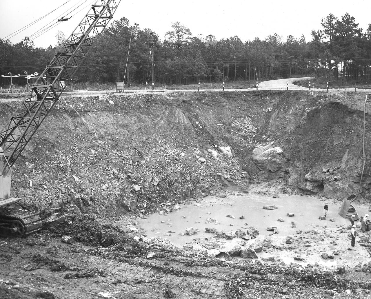
At its founding, the Marshall Space Flight Center (MSFC) inherited the Army’s Jupiter and Redstone test stands, but much larger facilities were needed for the giant stages of the Saturn V. From 1960 to 1964, the existing stands were remodeled and a sizable new test area was developed. The new comprehensive test complex for propulsion and structural dynamics was unique within the nation and the free world, and they remain so today because they were constructed with foresight to meet the future as well as on going needs. Construction of the S-IC Static test stand complex began in 1961 in the west test area of MSFC, and was completed in 1964. The S-IC static test stand was designed to develop and test the 138-ft long and 33-ft diameter Saturn V S-IC first stage, or booster stage, weighing in at 280,000 pounds. Required to hold down the brute force of a 7,500,000-pound thrust produced by 5 F-1 engines, the S-IC static test stand was designed and constructed with the strength of hundreds of tons of steel and 12,000,000 pounds of cement, planted down to bedrock 40 feet below ground level. The foundation walls, constructed with concrete and steel, are 4 feet thick. The base structure consists of four towers with 40-foot-thick walls extending upward 144 feet above ground level. The structure was topped by a crane with a 135-foot boom. With the boom in the upright position, the stand was given an overall height of 405 feet, placing it among the highest structures in Alabama at the time. In addition to the S-IC test stand, related facilities were built during this time. Built to the north of the massive S-IC test stand, was the F-1 Engine test stand. The F-1 test stand, a vertical engine firing test stand, 239 feet in elevation and 4,600 square feet in area at the base, was designed to assist in the development of the F-1 Engine. Capability was provided for static firing of 1.5 million pounds of thrust using liquid oxygen and kerosene. Like the S-IC stand, the foundation of the F-1 stand is keyed into the bedrock approximately 40 feet below grade. This photo, taken November 15, 1962, depicts the excavation process of the single engine F-1 stand site.
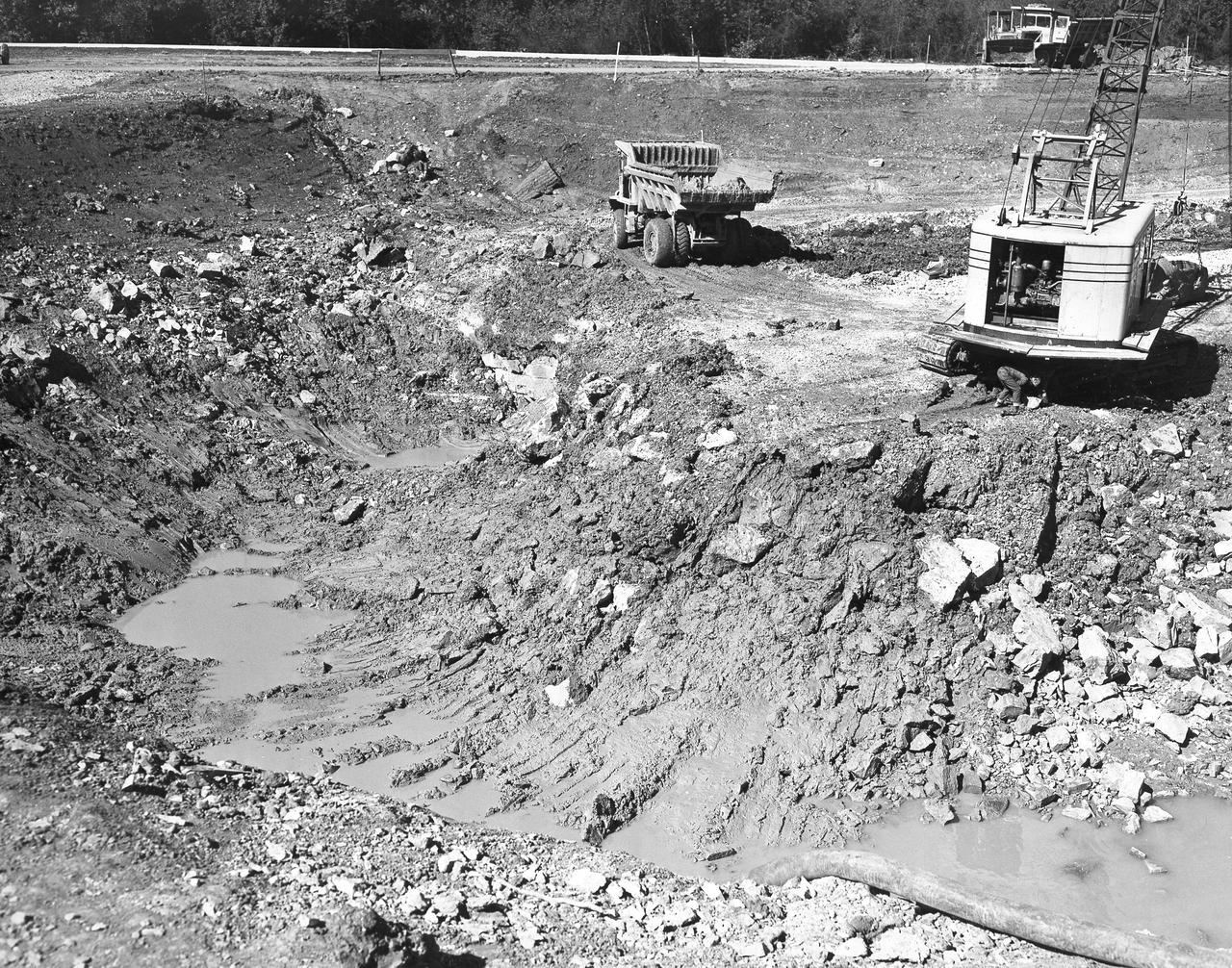
At its founding, the Marshall Space Flight Center (MSFC) inherited the Army’s Jupiter and Redstone test stands, but much larger facilities were needed for the giant stages of the Saturn V. From 1960 to 1964, the existing stands were remodeled and a sizable new test area was developed. The new comprehensive test complex for propulsion and structural dynamics was unique within the nation and the free world, and they remain so today because they were constructed with foresight to meet the future as well as on going needs. Construction of the S-IC Static test stand complex began in 1961 in the west test area of MSFC, and was completed in 1964. The S-IC static test stand was designed to develop and test the 138-ft long and 33-ft diameter Saturn V S-IC first stage, or booster stage, weighing in at 280,000 pounds. Required to hold down the brute force of a 7,500,000-pound thrust produced by 5 F-1 engines, the S-IC static test stand was designed and constructed with the strength of hundreds of tons of steel and 12,000,000 pounds of cement, planted down to bedrock 40 feet below ground level. The foundation walls, constructed with concrete and steel, are 4 feet thick. The base structure consists of four towers with 40-foot-thick walls extending upward 144 feet above ground level. The structure was topped by a crane with a 135-foot boom. With the boom in the upright position, the stand was given an overall height of 405 feet, placing it among the highest structures in Alabama at the time. In addition to the S-IC test stand, related facilities were built during this time. Built to the north of the massive S-IC test stand, was the F-1 Engine test stand. The F-1 test stand, a vertical engine firing test stand, 239 feet in elevation and 4,600 square feet in area at the base, was designed to assist in the development of the F-1 Engine. Capability was provided for static firing of 1.5 million pounds of thrust using liquid oxygen and kerosene. Like the S-IC stand, the foundation of the F-1 stand is keyed into the bedrock approximately 40 feet below grade. This photo, taken October 26, 1962, depicts the excavation process of the single engine F-1 stand.
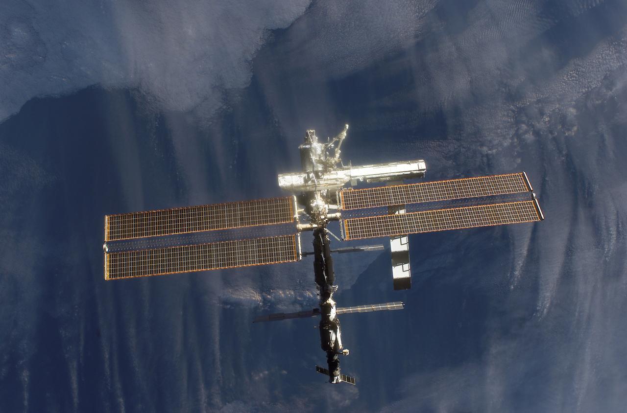
This image of the International Space Station (ISS) was photographed by one of the crewmembers of the STS-112 mission following separation from the Space Shuttle Orbiter Atlantis as the orbiter pulled away from the ISS. The newly added S1 truss is visible in the center frame. The primary payloads of this mission, International Space Station Assembly Mission 9A, were the Integrated Truss Assembly S-1 (S-One), the Starboard Side Thermal Radiator Truss,and the Crew Equipment Translation Aid (CETA) cart to the ISS. The S1 truss provides structural support for the orbiting research facility's radiator panels, which use ammonia to cool the Station's complex power system. The S1 truss was attached to the S0 (S Zero) truss, which was launched on April 8, 2002 aboard the STS-110, and flows 637 pounds of anhydrous ammonia through three heat rejection radiators. The truss is 45-feet long, 15-feet wide, 10-feet tall, and weighs approximately 32,000 pounds. The CETA cart was attached to the Mobil Transporter and will be used by assembly crews on later missions. Manufactured by the Boeing Company in Huntington Beach, California, the truss primary structure was transferred to the Marshall Space Flight Center in February 1999 for hardware installations and manufacturing acceptance testing. The launch of the STS-112 mission occurred on October 7, 2002, and its 11-day mission ended on October 18, 2002.
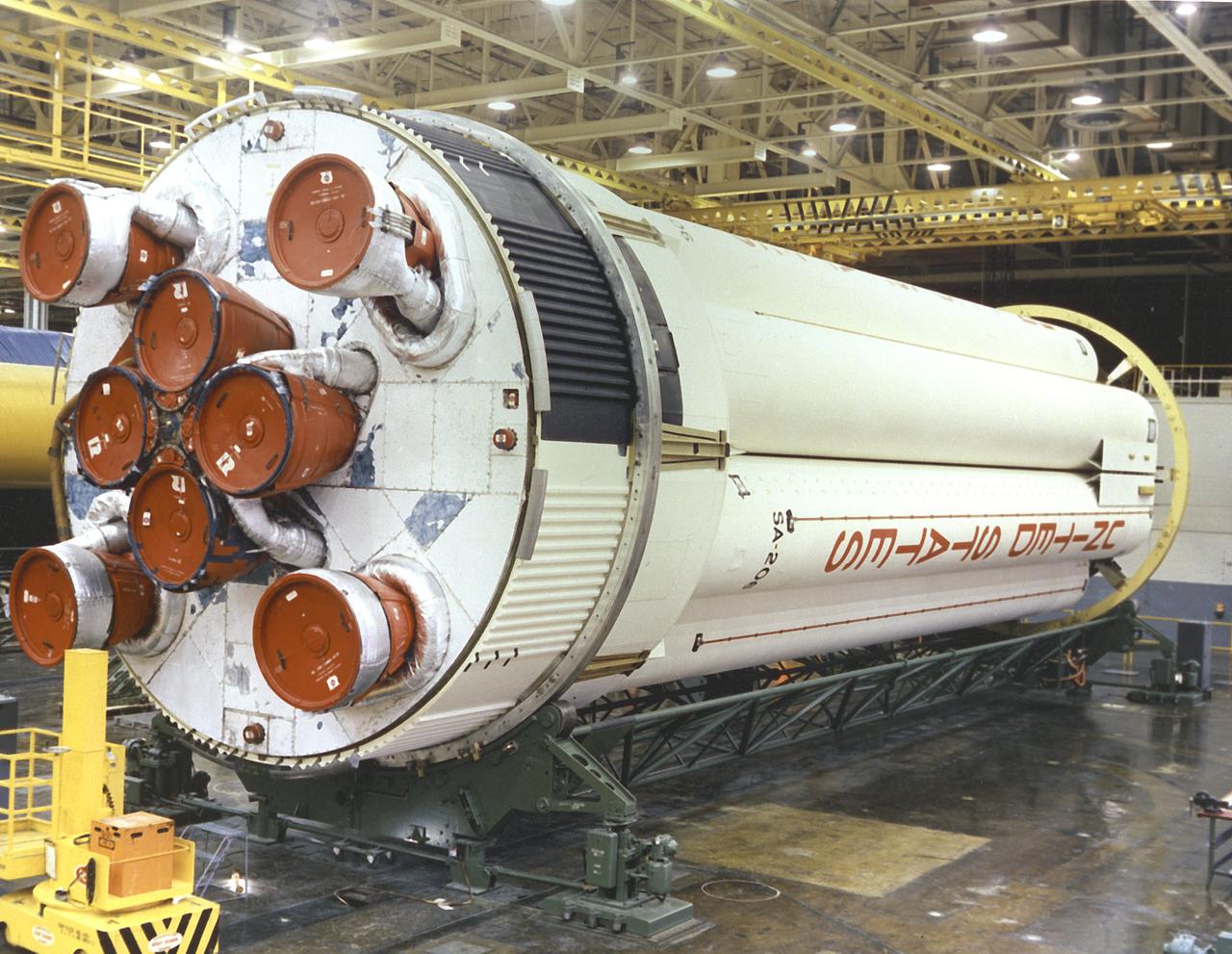
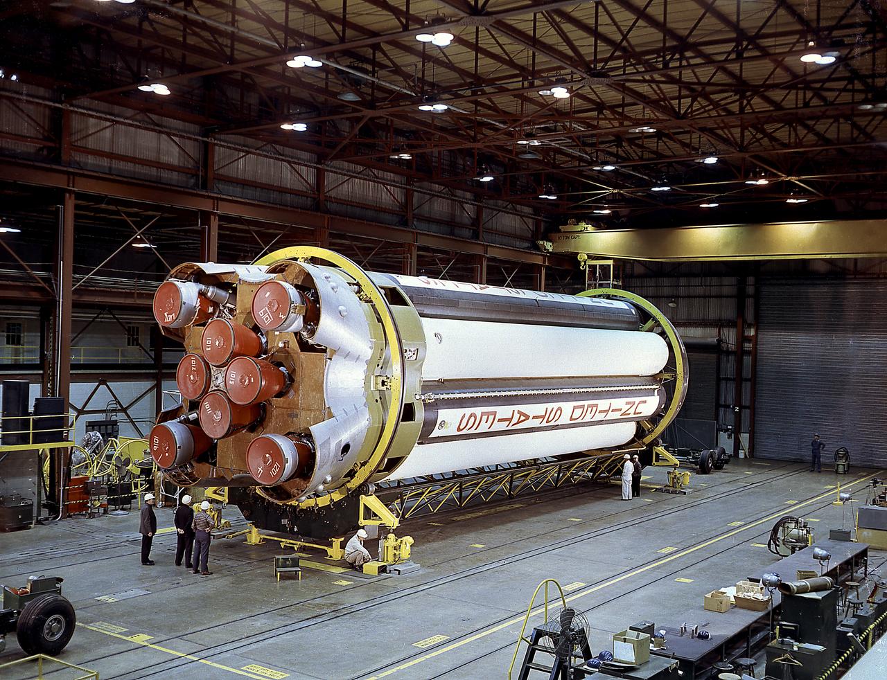
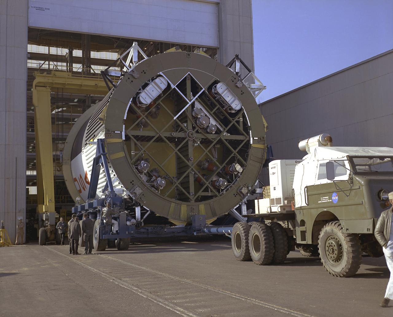
The Saturn 1B S-IB (first) stage being prepared for shipment at Michoud Assembly Facility (MAF), near New Orleans, Louisiana. Developed by the Marshall Space Flight Center and built by the Chrysler Corporation at MAF, the S-IB stage utilized the eight H-1 engines and each produced 200,000 pounds of thrust, a combined thrust of 1,600,000 pounds.
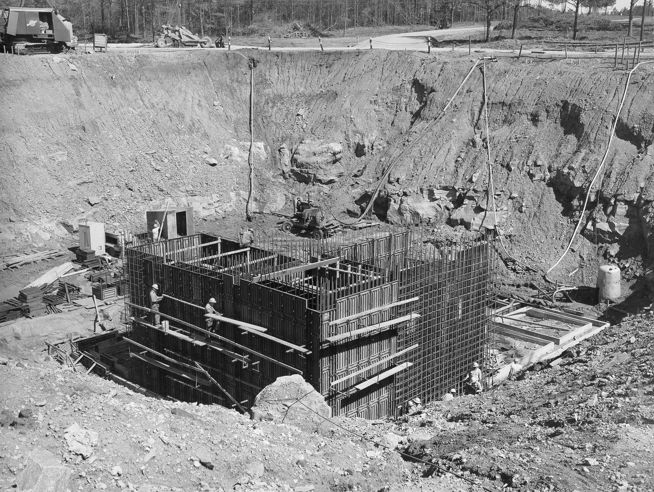
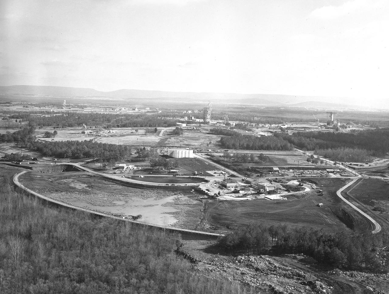
At its founding, the Marshall Space Flight Center (MSFC) inherited the Army’s Jupiter and Redstone test stands, but much larger facilities were needed for the giant stages of the Saturn V. From 1960 to 1964, the existing stands were remodeled and a sizable new test area was developed. The new comprehensive test complex for propulsion and structural dynamics was unique within the nation and the free world, and they remain so today because they were constructed with foresight to meet the future as well as on going needs. Construction of the S-IC Static test stand complex began in 1961 in the west test area of MSFC, and was completed in 1964. The S-IC static test stand was designed to develop and test the 138-ft long and 33-ft diameter Saturn V S-IC first stage, or booster stage, weighing in at 280,000 pounds. Required to hold down the brute force of a 7,500,000-pound thrust produced by 5 F-1 engines, the S-IC static test stand was designed and constructed with the strength of hundreds of tons of steel and 12,000,000 pounds of cement, planted down to bedrock 40 feet below ground level. The foundation walls, constructed with concrete and steel, are 4 feet thick. The base structure consists of four towers with 40-foot-thick walls extending upward 144 feet above ground level. The structure was topped by a crane with a 135-foot boom. With the boom in the upright position, the stand was given an overall height of 405 feet, placing it among the highest structures in Alabama at the time. In addition to the stand itself, related facilities were constructed during this time. North of the massive S-IC test stand, the F-1 Engine test stand was built. Designed to assist in the development of the F-1 Engine, the F-1 test stand is a vertical engine firing test stand, 239 feet in elevation and 4,600 square feet in area at the base. Capability was provided for static firing of 1.5 million pounds of thrust using liquid oxygen and kerosene. Like the S-IC stand, the foundation of the F-1 stand is keyed into the bedrock approximately 40 feet below grade. This photo depicts the construction of the F-1 test stand as of August 13, 1963. All four of its tower legs are well underway into the skyline.
At its founding, the Marshall Space Flight Center (MSFC) inherited the Army’s Jupiter and Redstone test stands, but much larger facilities were needed for the giant stages of the Saturn V. From 1960 to 1964, the existing stands were remodeled and a sizable new test area was developed. The new comprehensive test complex for propulsion and structural dynamics was unique within the nation and the free world, and they remain so today because they were constructed with foresight to meet the future as well as on going needs. Construction of the S-IC Static test stand complex began in 1961 in the west test area of MSFC, and was completed in 1964. The S-IC static test stand was designed to develop and test the 138-ft long and 33-ft diameter Saturn V S-IC first stage, or booster stage, weighing in at 280,000 pounds. Required to hold down the brute force of a 7,500,000-pound thrust produced by 5 F-1 engines, the S-IC static test stand was designed and constructed with the strength of hundreds of tons of steel and 12,000,000 pounds of cement, planted down to bedrock 40 feet below ground level. The foundation walls, constructed with concrete and steel, are 4 feet thick. The base structure consists of four towers with 40-foot-thick walls extending upward 144 feet above ground level. The structure was topped by a crane with a 135-foot boom. With the boom in the upright position, the stand was given an overall height of 405 feet, placing it among the highest structures in Alabama at the time. In addition to the stand itself, related facilities were constructed during this time. North of the massive S-IC test stand, the F-1 Engine test stand was built. Designed to assist in the development of the F-1 Engine, the F-1 test stand is a vertical engine firing test stand, 239 feet in elevation and 4,600 square feet in area at the base. Capability was provided for static firing of 1.5 million pounds of thrust using liquid oxygen and kerosene. Like the S-IC stand, the foundation of the F-1 stand is keyed into the bedrock approximately 40 feet below grade. This photo depicts the construction of the F-1 test stand as of September 30, 1963.
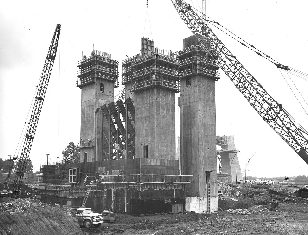
At its founding, the Marshall Space Flight Center (MSFC) inherited the Army’s Jupiter and Redstone test stands, but much larger facilities were needed for the giant stages of the Saturn V. From 1960 to 1964, the existing stands were remodeled and a sizable new test area was developed. The new comprehensive test complex for propulsion and structural dynamics was unique within the nation and the free world, and they remain so today because they were constructed with foresight to meet the future as well as on going needs. Construction of the S-IC Static test stand complex began in 1961 in the west test area of MSFC, and was completed in 1964. The S-IC static test stand was designed to develop and test the 138-ft long and 33-ft diameter Saturn V S-IC first stage, or booster stage, weighing in at 280,000 pounds. Required to hold down the brute force of a 7,500,000-pound thrust produced by 5 F-1 engines, the S-IC static test stand was designed and constructed with the strength of hundreds of tons of steel and 12,000,000 pounds of cement, planted down to bedrock 40 feet below ground level. The foundation walls, constructed with concrete and steel, are 4 feet thick. The base structure consists of four towers with 40-foot-thick walls extending upward 144 feet above ground level. The structure was topped by a crane with a 135-foot boom. With the boom in the upright position, the stand was given an overall height of 405 feet, placing it among the highest structures in Alabama at the time. In addition to the stand itself, related facilities were constructed during this time. North of the massive S-IC test stand, the F-1 Engine test stand was built. Designed to assist in the development of the F-1 Engine, the F-1 test stand is a vertical engine firing test stand, 239 feet in elevation and 4,600 square feet in area at the base. Capability was provided for static firing of 1.5 million pounds of thrust using liquid oxygen and kerosene. Like the S-IC stand, the foundation of the F-1 stand is keyed into the bedrock approximately 40 feet below grade. This photo depicts the construction of the F-1 test stand as of September 5, 1963.
This photograph depicts a view of the test firing of all five F-1 engines for the Saturn V S-IC test stage at the Marshall Space Flight Center. The S-IC stage is the first stage, or booster, of a 364-foot long rocket that ultimately took astronauts to the Moon. Operating at maximum power, all five of the engines produced 7,500,000 pounds of thrust. The S-IC Static Test Stand was designed and constructed with the strength of hundreds of tons of steel and cement, planted down to bedrock 40 feet below ground level, and was required to hold down the brute force of the 7,500,000-pound thrust. The structure was topped by a crane with a 135-foot boom. With the boom in the up position, the stand was given an overall height of 405 feet, placing it among the highest structures in Alabama at the time. When the Saturn V S-IC first stage was placed upright in the stand , the five F-1 engine nozzles pointed downward on a 1,900-ton, water-cooled deflector. To prevent melting damage, water was sprayed through small holes in the deflector at the rate 320,000 gallons per minutes.
This photograph depicts a view of the test firing of all five F-1 engines for the Saturn V S-IC test stage at the Marshall Space Flight Center. The S-IC stage is the first stage, or booster, of a 364-foot long rocket that ultimately took astronauts to the Moon. Operating at maximum power, all five of the engines produced 7,500,000 pounds of thrust. The S-IC Static Test Stand was designed and constructed with the strength of hundreds of tons of steel and cement, planted down to bedrock 40 feet below ground level, and was required to hold down the brute force of the 7,500,000-pound thrust. The structure was topped by a crane with a 135-foot boom. With the boom in the up position, the stand was given an overall height of 405 feet, placing it among the highest structures in Alabama at the time. When the Saturn V S-IC first stage was placed upright in the stand , the five F-1 engine nozzles pointed downward on a 1,900-ton, water-cooled deflector. To prevent melting damage, water was sprayed through small holes in the deflector at the rate 320,000 gallons per minutes
Workers at the Michoud Assembly Facility near New Orleans, Louisiana install the H-1 engines into the S-IB stage, the Saturn IB launch vehicle's first stage. Developed by the Marshall Space Flight Center and built by the Chrysler Corporation at MAF, the 90,000-pound booster utilized eight H-1 engines to produce a combined thrust of 1,600,000 pounds.
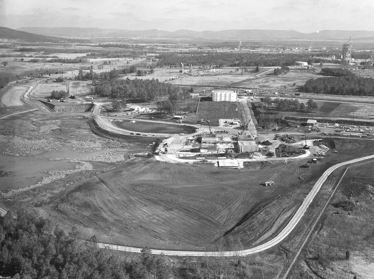
At its founding, the Marshall Space Flight Center (MSFC) inherited the Army’s Jupiter and Redstone test stands, but much larger facilities were needed for the giant stages of the Saturn V. From 1960 to 1964, the existing stands were remodeled and a sizable new test area was developed. The new comprehensive test complex for propulsion and structural dynamics was unique within the nation and the free world, and they remain so today because they were constructed with foresight to meet the future as well as on going needs. Construction of the S-IC Static test stand complex began in 1961 in the west test area of MSFC, and was completed in 1964. The S-IC static test stand was designed to develop and test the 138-ft long and 33-ft diameter Saturn V S-IC first stage, or booster stage, weighing in at 280,000 pounds. Required to hold down the brute force of a 7,500,000-pound thrust produced by 5 F-1 engines, the S-IC static test stand was designed and constructed with the strength of hundreds of tons of steel and 12,000,000 pounds of cement, planted down to bedrock 40 feet below ground level. The foundation walls, constructed with concrete and steel, are 4 feet thick. The base structure consists of four towers with 40-foot-thick walls extending upward 144 feet above ground level. The structure was topped by a crane with a 135-foot boom. With the boom in the upright position, the stand was given an overall height of 405 feet, placing it among the highest structures in Alabama at the time. In addition to the stand itself, related facilities were constructed during this time. Built directly east of the test stand was the Block House, which served as the control center for the test stand. The two were connected by a narrow access tunnel which housed the cables for the controls. The F-1 Engine test stand was built north of the massive S-IC test stand. The F-1 test stand is a vertical engine firing test stand, 239 feet in elevation and 4,600 square feet in area at the base, and was designed to assist in the development of the F-1 Engine. Capability is provided for static firing of 1.5 million pounds of thrust using liquid oxygen and kerosene. Like the S-IC stand, the foundation of the F-1 stand is keyed into the bedrock approximately 40 feet below grade. This aerial photograph, taken January 15, 1963, gives a close overall view of the newly developed test complex. Depicted in the forefront center is the S-IC test stand with towers prominent, the Block House is seen in the center just above the S-IC test stand, and the large hole to the left, located midway between the two is the F-1 test stand site.
At its founding, the Marshall Space Flight Center (MSFC) inherited the Army’s Jupiter and Redstone test stands, but much larger facilities were needed for the giant stages of the Saturn V. From 1960 to 1964, the existing stands were remodeled and a sizable new test area was developed. The new comprehensive test complex for propulsion and structural dynamics was unique within the nation and the free world, and they remain so today because they were constructed with foresight to meet the future as well as on going needs. Construction of the S-IC Static test stand complex began in 1961 in the west test area of MSFC, and was completed in 1964. The S-IC static test stand was designed to develop and test the 138-ft long and 33-ft diameter Saturn V S-IC first stage, or booster stage, weighing in at 280,000 pounds. Required to hold down the brute force of a 7,500,000-pound thrust produced by 5 F-1 engines, the S-IC static test stand was designed and constructed with the strength of hundreds of tons of steel and 12,000,000 pounds of cement, planted down to bedrock 40 feet below ground level. The foundation walls, constructed with concrete and steel, are 4 feet thick. The base structure consists of four towers with 40-foot-thick walls extending upward 144 feet above ground level. The structure was topped by a crane with a 135-foot boom. With the boom in the upright position, the stand was given an overall height of 405 feet, placing it among the highest structures in Alabama at the time. In addition to the stand itself, related facilities were constructed during this time. Built directly east of the test stand was the Block House, which served as the control center for the test stand. The two were connected by a narrow access tunnel which housed the cables for the controls. The F-1 Engine test stand was built north of the massive S-IC test stand. The F-1 test stand is a vertical engine firing test stand, 239 feet in elevation and 4,600 square feet in area at the base, and was designed to assist in the development of the F-1 Engine. Capability is provided for static firing of 1.5 million pounds of thrust using liquid oxygen and kerosene. Like the S-IC stand, the foundation of the F-1 stand is keyed into the bedrock approximately 40 feet below grade. This aerial photograph, taken January 15, 1963 gives an overall view of the construction progress of the newly developed test complex. The large white building located in the center is the Block House. Just below and to the right of it is the S-IC test stand. The large hole to the left of the S-IC stand is the F-1 test stand site.
At its founding, the Marshall Space Flight Center (MSFC) inherited the Army’s Jupiter and Redstone test stands, but much larger facilities were needed for the giant stages of the Saturn V. From 1960 to 1964, the existing stands were remodeled and a sizable new test area was developed. The new comprehensive test complex for propulsion and structural dynamics was unique within the nation and the free world, and they remain so today because they were constructed with foresight to meet the future as well as on going needs. Construction of the S-IC Static test stand complex began in 1961 in the west test area of MSFC, and was completed in 1964. The S-IC static test stand was designed to develop and test the 138-ft long and 33-ft diameter Saturn V S-IC first stage, or booster stage, weighing in at 280,000 pounds. Required to hold down the brute force of a 7,500,000-pound thrust produced by 5 F-1 engines, the S-IC static test stand was designed and constructed with the strength of hundreds of tons of steel and 12,000,000 pounds of cement, planted down to bedrock 40 feet below ground level. The foundation walls, constructed with concrete and steel, are 4 feet thick. The base structure consists of four towers with 40-foot-thick walls extending upward 144 feet above ground level. The structure was topped by a crane with a 135-foot boom. With the boom in the upright position, the stand was given an overall height of 405 feet, placing it among the highest structures in Alabama at the time. In addition to the stand itself, related facilities were constructed during this time. Built directly east of the test stand was the Block House, which served as the control center for the test stand. The two were connected by a narrow access tunnel which housed the cables for the controls. The F-1 Engine test stand was built north of the massive S-IC test stand. The F-1 test stand is a vertical engine firing test stand, 239 feet in elevation and 4,600 square feet in area at the base, and was designed to assist in the development of the F-1 Engine. Capability is provided for static firing of 1.5 million pounds of thrust using liquid oxygen and kerosene. Like the S-IC stand, the foundation of the F-1 stand is keyed into the bedrock approximately 40 feet below grade. Looking North, this aerial taken January 15, 1963, gives a closer view of the deep hole for the F-1 test stand site in the forefront. The S-IC test stand with towers prominent is to the right of center, and the Block House is seen left of center.
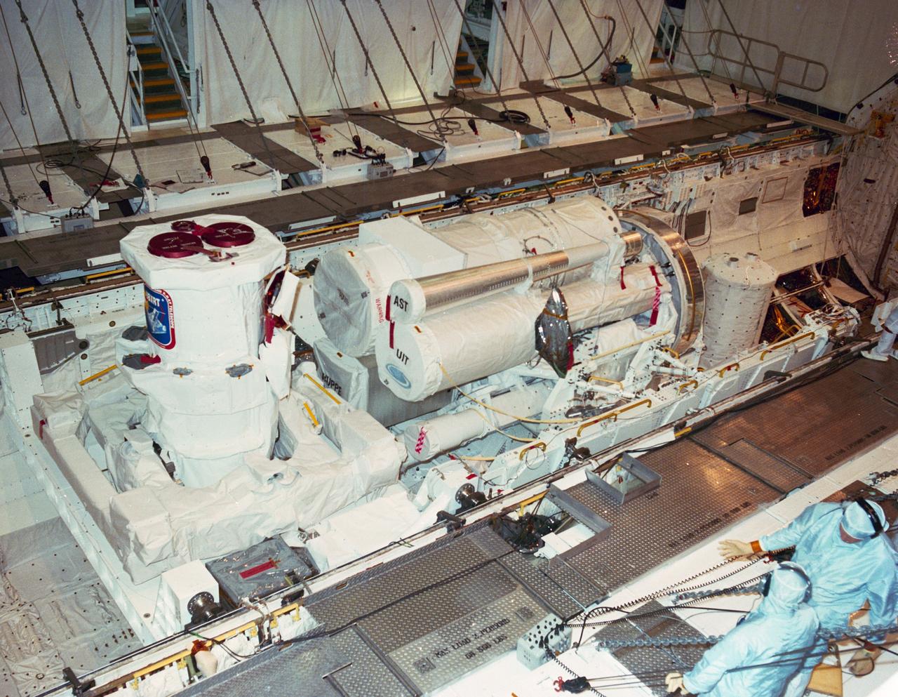
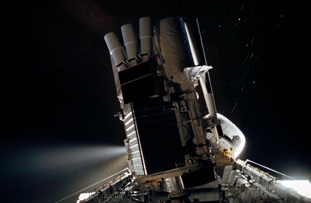
STS-35 Astronomy Laboratory 1 (ASTRO-1) is installed in Columbia's, Orbiter Vehicle (OV) 102's, payload bay (PLB) at the Kennedy Space Center (KSC) Orbiter Processing Facility (OPF). On the left, in the aft PLB is the Broad Band X Ray Telescope (BBXRT) mounted on the two axis pointing system (TAPS). In the center, the three ultraviolet telescopes - Wisconsin Ultraviolet Photo-Polarimeter Experiment (WUPPE), the Hopkins Ultraviolet Telescope (HUT), and the Ultraviolet Imaging Telescope (UIT) - are mounted on the instrument pointing system (IPS) and are in stowed position. At the far right is the Spacelab Pallet System (SPS) igloo. View provided by KSC with alternate number KSSC-90PC-421.
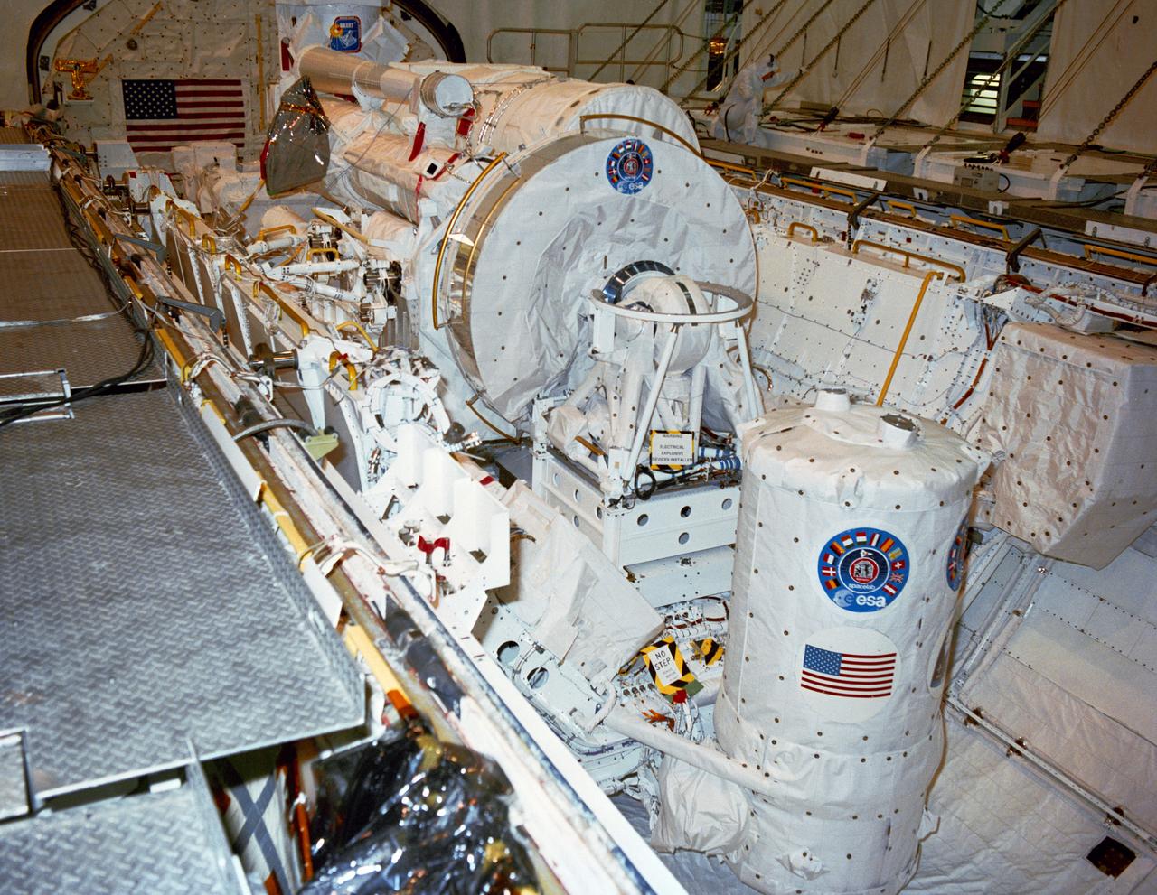
S90-36708 (7 May 1990) --- STS-35 Astronomy Laboratory 1 (ASTRO-1) view shows its telescopes, instrument pointing system (IPS), and support equipment installed in Columbia's, Orbiter Vehicle (OV) 102's, payload bay (PLB) at the Kennedy Space Center (KSC) Orbiter Processing Facility (OPF). In the foreground is the Spacelab Pallet System (SPS) igloo. The stowed IPS with its three ultraviolet telescopes appears in the center of the picture. In the background, the Broad Band X Ray Telescope (BBXRT) two axis pointing system (TAPS) is barely visible. View provided by KSC with alternate number KSC-90PC-423.
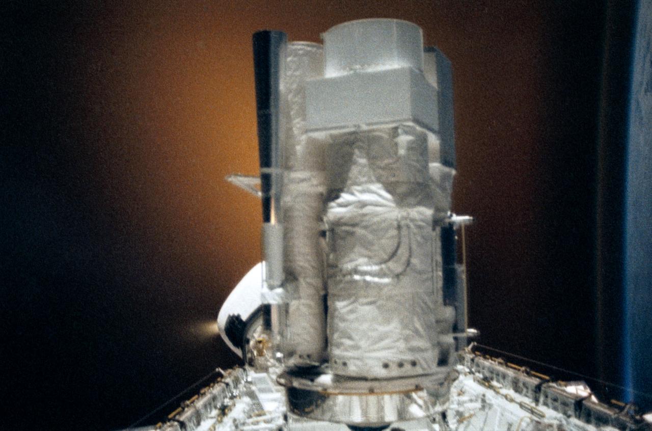
STS035-28-006 (2-10 Dec 1990) --- STS-35 Astronomy Laboratory 1 (ASTRO-1) telescopes, in on-orbit operating position in the payload bay (PLB), are silhouetted against an reaction control system (RCS) right thruster firing. Three ultraviolet telescopes are mounted and precisely co-aligned on a common structure, called the cruciform, that is attached to the instrument pointing system (IPS). Here the IPS holds the telescopes in a position that is parallel to the Earth's limb below. Visible on the cruciform are the star tracker (S TRK) (silver cone at the top), the Ultraviolet Imaging Telescope (UIT) (behind S TRK), and the Hopkins Ultraviolet Telescope(HUT).
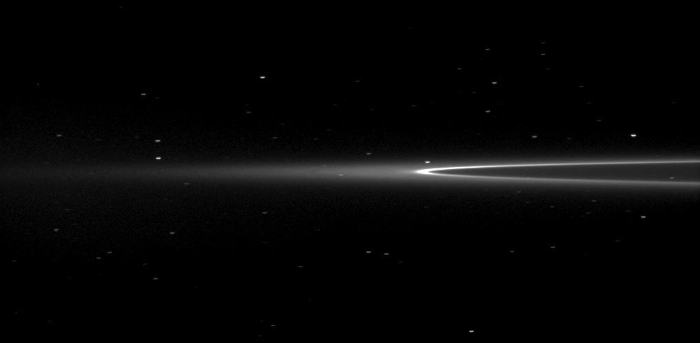
NASA Cassini spacecraft looks toward Saturn tiny moon Aegaeon within the G-ring arc. The moonlet Aegaeon formerly known as S/2008 S 1 cant be seen in this image, but it orbits in the bright arc of Saturn faint G ring shown here.
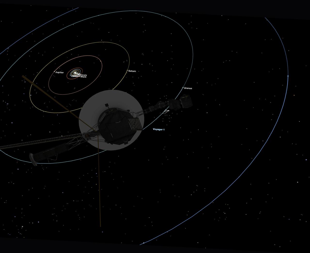
This simulated view, made using NASA's Eyes on the Solar System app, approximates Voyager 1's perspective when it took its final series of images known as the "Family Portrait of the Solar System," including the "Pale Blue Dot" image. https://photojournal.jpl.nasa.gov/catalog/PIA23681
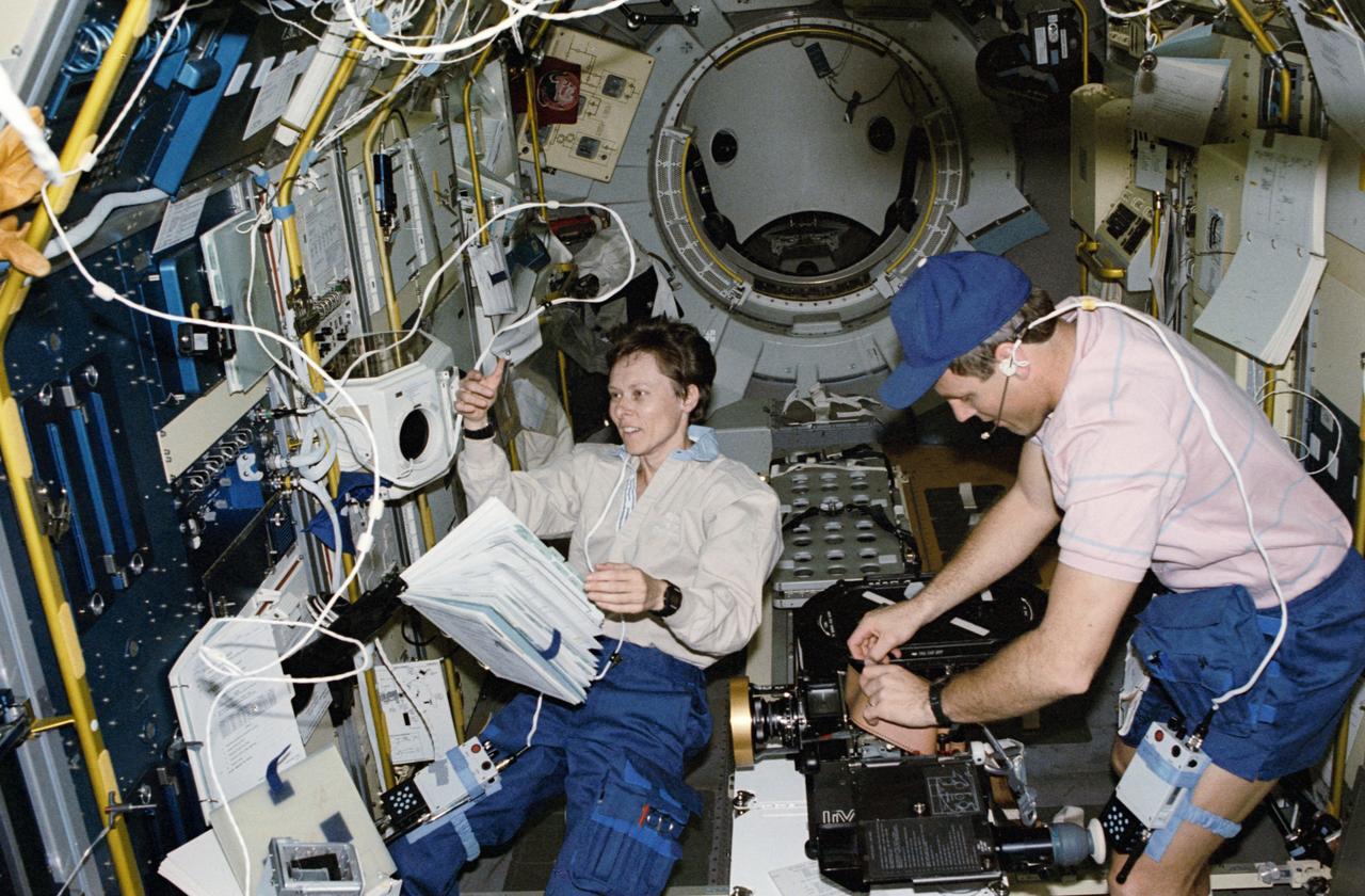
STS042-201-009 (22-30 Jan 1992) --- Canadian Roberta L. Bondar, payload specialist representing the Canadian Space Agency (CSA), works at the International Microgravity Laboratory's (IML-1) biorack while astronaut Stephen S. Oswald, pilot, changes a film magazine on the IMAX camera. The two were joined by five fellow crew members for eight-days of scientific research aboard the Space Shuttle Discovery in Earth-orbit. Most of their on-duty time was spent in this IML-1 Science Module, positioned in the cargo bay and attached via a tunnel to Discovery's airlock.
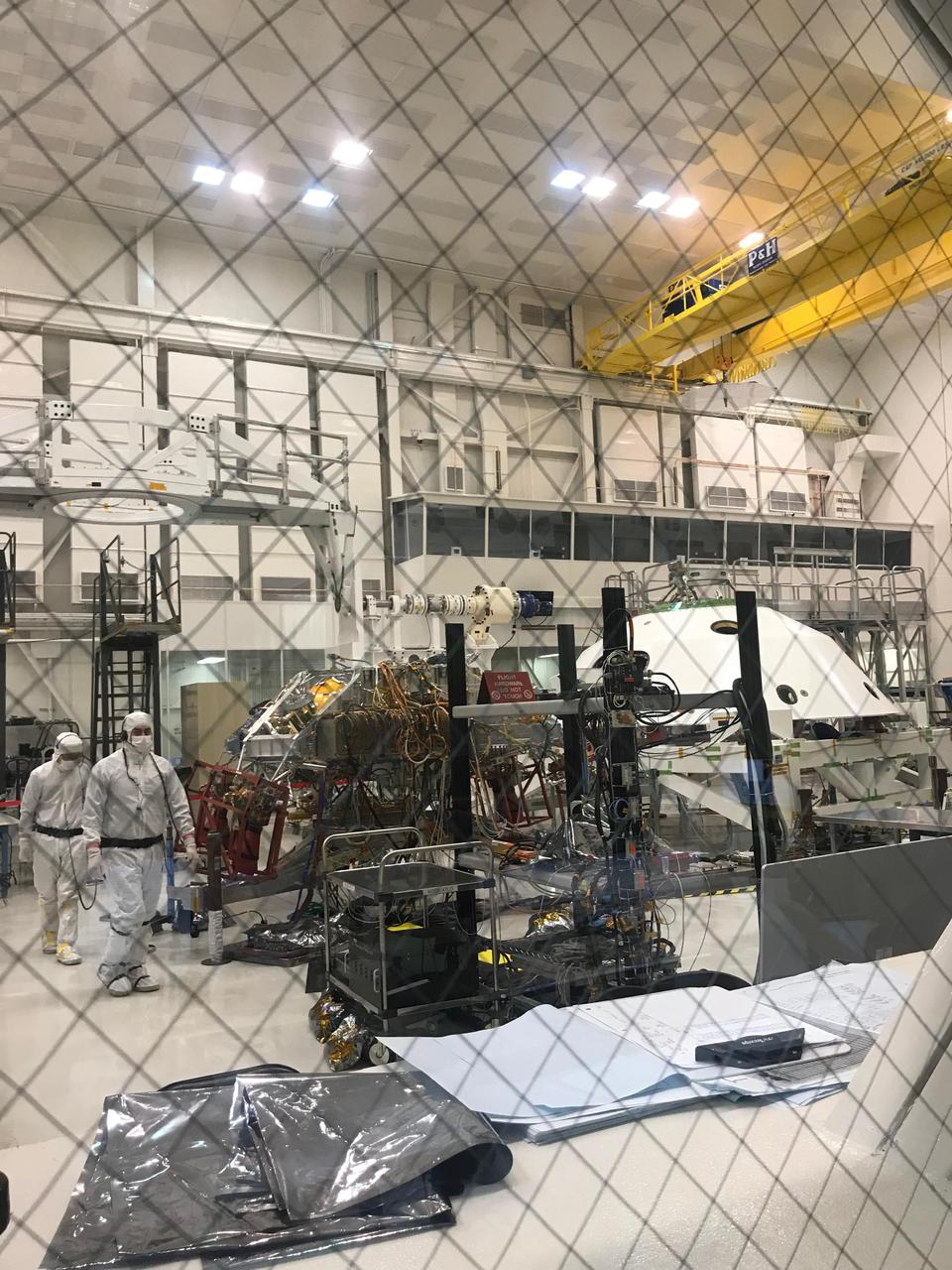
Technicians working Mars 2020's System's Test 1 approach their workstation in the Spacecraft Assembly Facility at NASA's Jet Propulsion Laboratory in Pasadena, Calif. Over two weeks in January 2019, 72 engineers and technicians assigned to the 2020 mission took over the High Bay 1 cleanroom in JPL's Spacecraft Assembly Facility to put the software and electrical systems aboard the mission's cruise, entry capsule, descent stage and rover through their paces. https://photojournal.jpl.nasa.gov/catalog/PIA23097
STS035-35-007 (2-10 Dec 1990) --- During the STS-35 mission, the Astronomy Laboratory 1 (ASTRO-1) payload, in its on-orbit operating configuration in the payload bay (PLB), is silhouetted against the firing of a reaction control system (RCS) jet. In the center of the frame, three ultraviolet telescopes are mounted and precisely co-aligned on a common structure, called the cruciform, that is attached to the instrument pointing system (IPS). Visible on the cruciform are Integrated Radiator System (IRS) (silver box on left), the Optical Sensor Package (OSP) (above IRS), the Ultraviolet Imaging Telescope (UIT), and the star tracker (S TRK) (far right). A right RCS jet is fired during this maneuver of Columbia, Orbiter Vehicle (OV) 102.
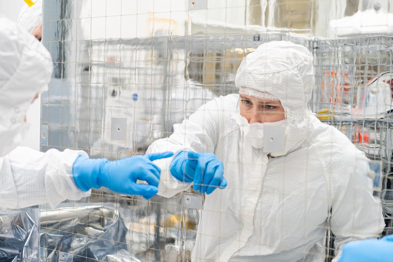
Contamination control technician Sydnie Heiman inspects one of OSAM-1's radiator panels inside the cleanroom at Goddard Space Flight Center, Greenbelt Md., July 10, 2023. This photo has been reviewed by OSAM1 project management and the Export Control Office and is released for public view. NASA/Mike Guinto
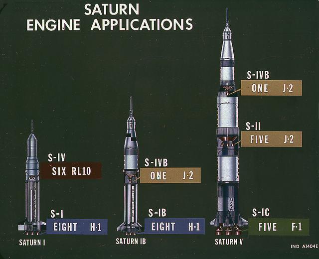
This image illustrates the basic differences between the three Saturn launch vehicles developed by the Marshall Space Flight Center. The Saturn I, consisted of two stages, the S-I (eight H-1 engines) and the S-IV (six RL-10 engines). The Saturn IB (center) also consisted of two stages, the S-IB (eight H-1 engines) and the S-IVB (one J-2 engine). The Saturn V consisted of three stages, the S-IC (five F-1 engines), the S-II (five J-2 engines), and the S-IVB (one J-2 engine).

A spider beam for cornecting the Saturn I fuel tanks is being positioned in the fabrication and engineering laboratory of the Marshall Space Flight Center (MSFC).

Goddard’s 85th Intracenter Run was held on May 2, 2018 near Child Development Center 1/2/3 place in Children’s race
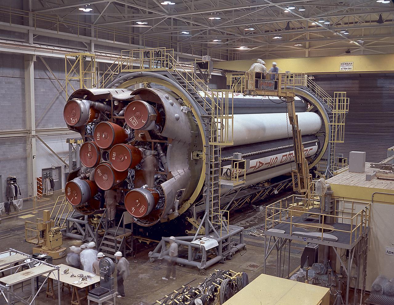
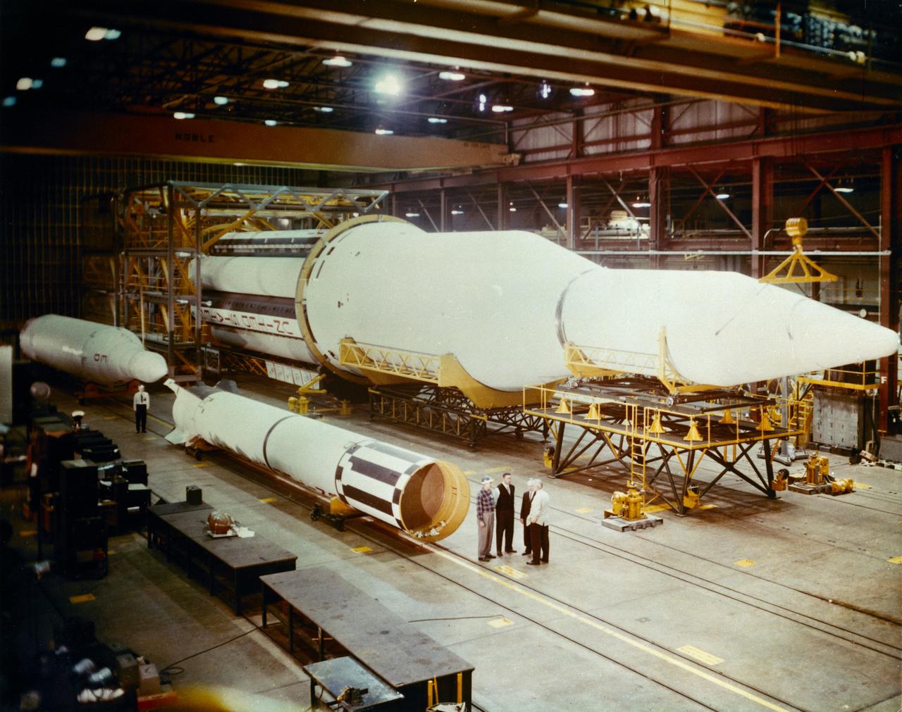
The photograph shows the completed Saturn 1 S-1 stage (booster) during the checkout in the Marshall Space Flight Center, building 4705, January 23, 1961. The Saturn I S-I stage had eight H-1 engines clustered, using liquid oxygen/kerosene-1 (LOX/RP-1) propellants capable of producing a total of 1,500,000 pounds of thrust.
The completely assembled Saturn 1 S-1 stage is being ready for checkout in the Marshall Space Flight Center, building 4705, January 18, 1961. The Saturn I S-I stage had eight H-1 engines clustered, using liquid oxygen/kerosene-1 (LOX/RP-1) propellants capable of producing a total of 1,500,000 pounds of thrust.
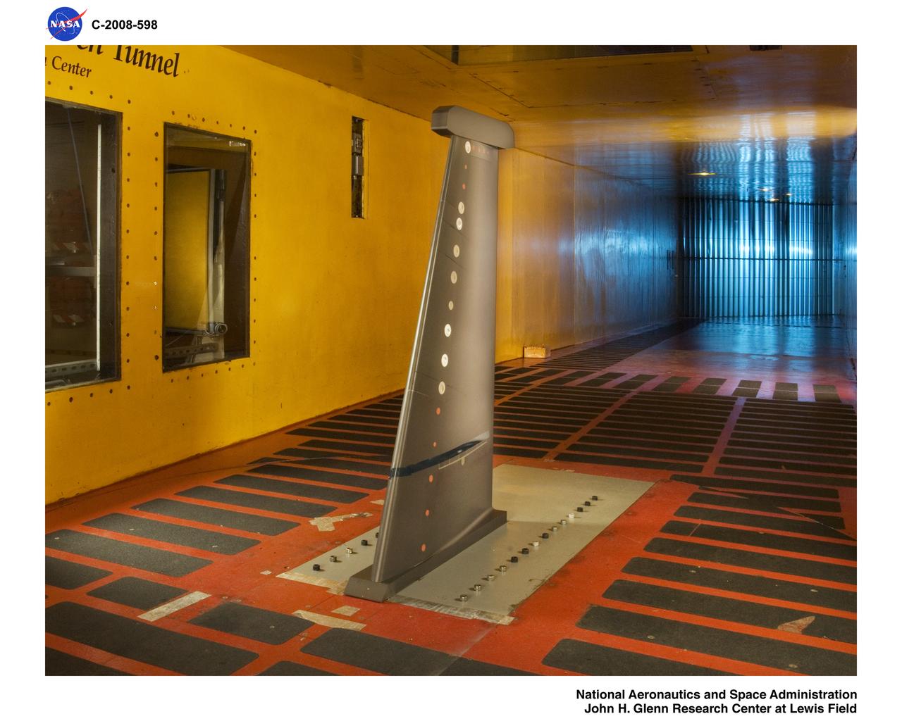
S-3 Viking 1/3 Wing Section in the Icing Research Tunnel
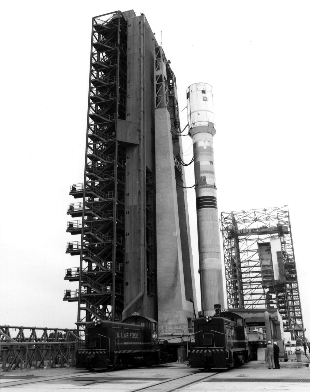
The Titan/Centaur-6 launch vehicle was moved to Launch Complex 41 at Kennedy Space Center in Florida to complete checkout procedures in preparation for launch. The photo is dated January 1977. This launch vehicle carried Voyager 1 into space on September 5, 1977. https://photojournal.jpl.nasa.gov/catalog/PIA21739
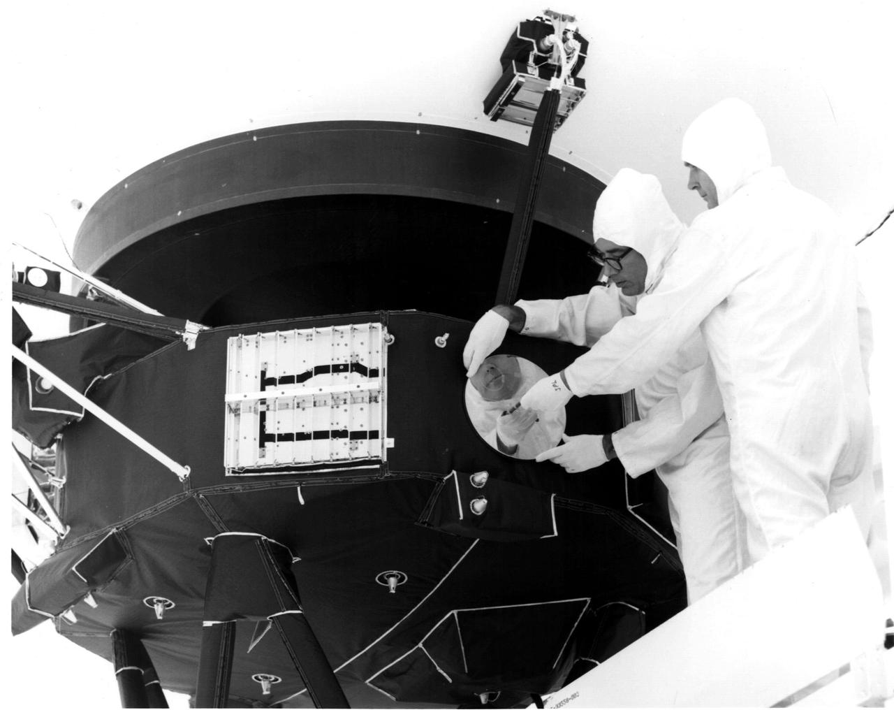
Engineers secure the cover over the Voyager 1 Golden Record in this archival image from 1977. https://photojournal.jpl.nasa.gov/catalog/PIA21740
The S-I stages for the Saturn I (SA-1 at right and SA-2 at left) are being assembled at the Marshall Space Flight Center, building 4705. The Saturn I S-I stage had eight H-1 engines clustered, using liquid oxygen/kerosene-1 (LOX/RP-1) propellants capable of producing a total of 1,500,000 pounds of thrust.
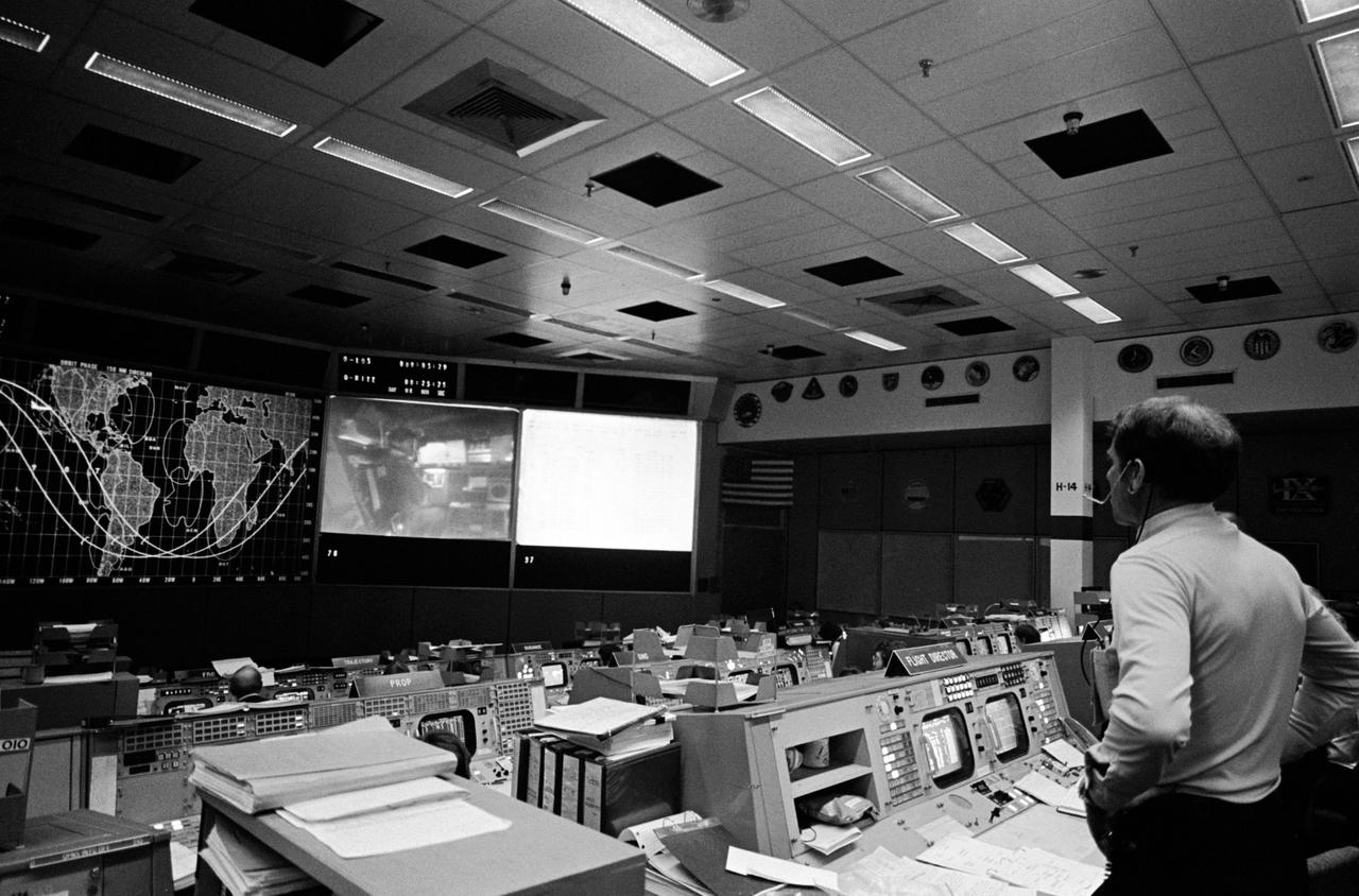
S81-30216 (12 April 1981) --- Astronaut Joe H. Engle, backup crew commander for STS-1, watches a large screen in the mission operations control room of the Johnson Space Center?s Mission Control Center during the STS-1 flight?s prime crew commander?s status report. Astronaut John W. Young, commander, can be seen in the image at left center, which is displayed via rear screen projector. Photo credit: NASA
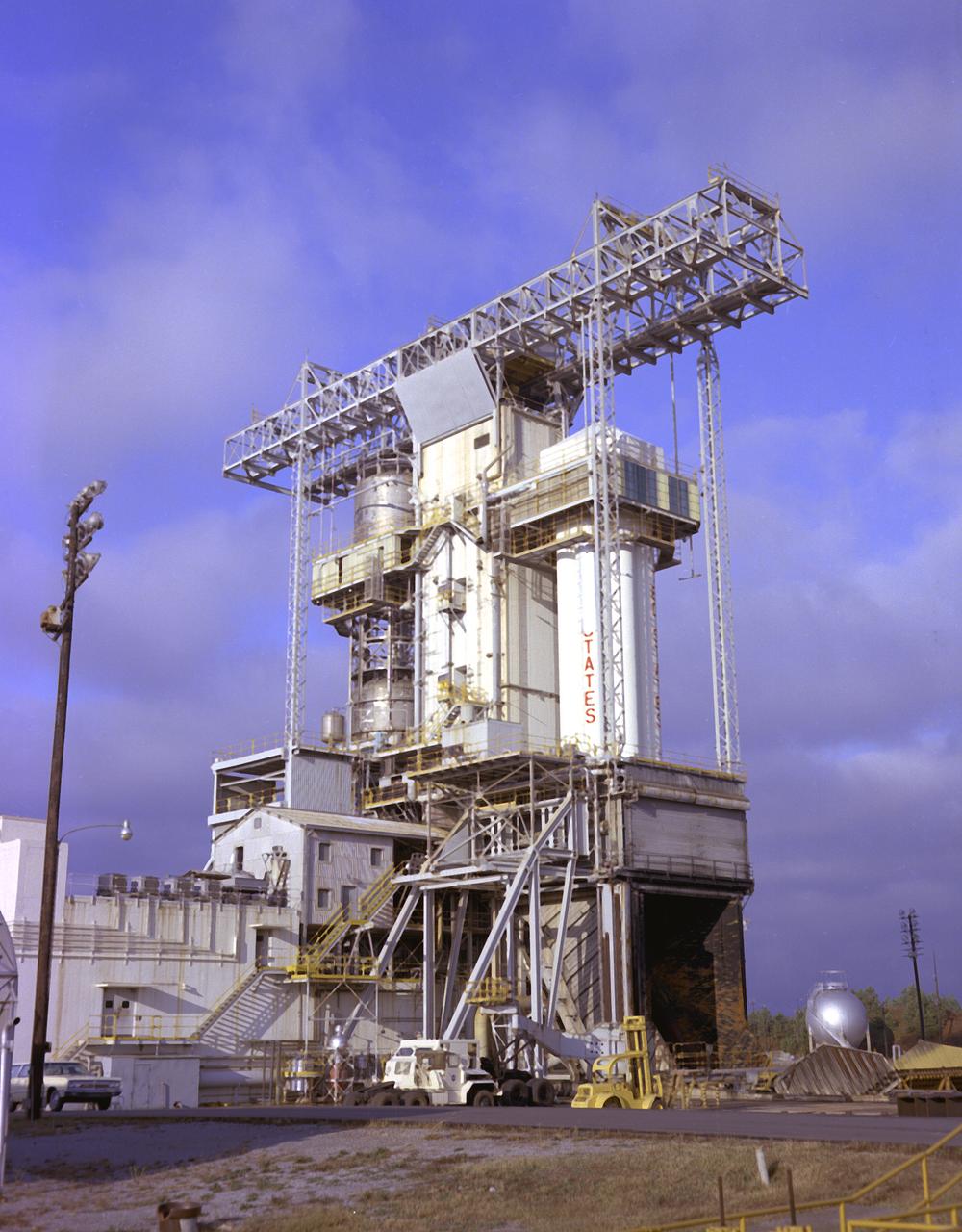
Test firing of the Saturn I S-I Stage (S-1-10) at the Marshall Space Flight Center. This test stand was originally constructed in 1951 and sometimes called the Redstone or T tower. In l961, the test stand was modified to permit static firing of the S-I/S-IB stages, which produced a total thrust of 1,600,000 pounds. The name of the stand was then changed to the S-IB Static Test Stand.
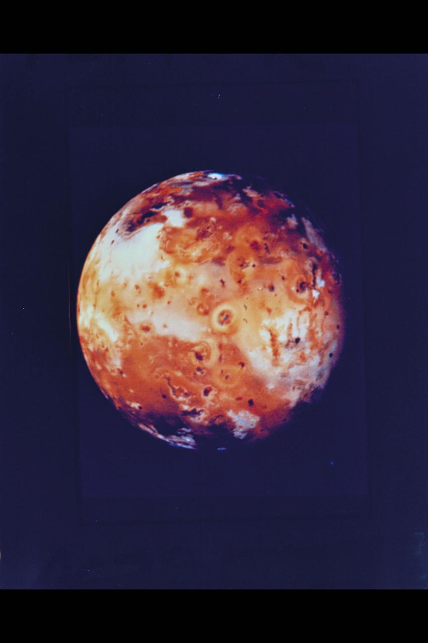
Voyager 1's look at Jupiter's moon Io JPL ref No. P-21457
iss065-s-001 (July 1, 2020) --- The official insignia of the Expedition 65 mission aboard the International Space Station.

S96-13321 (1 April 1993) --- Astronaut Marsha S. Ivins, mission specialist.
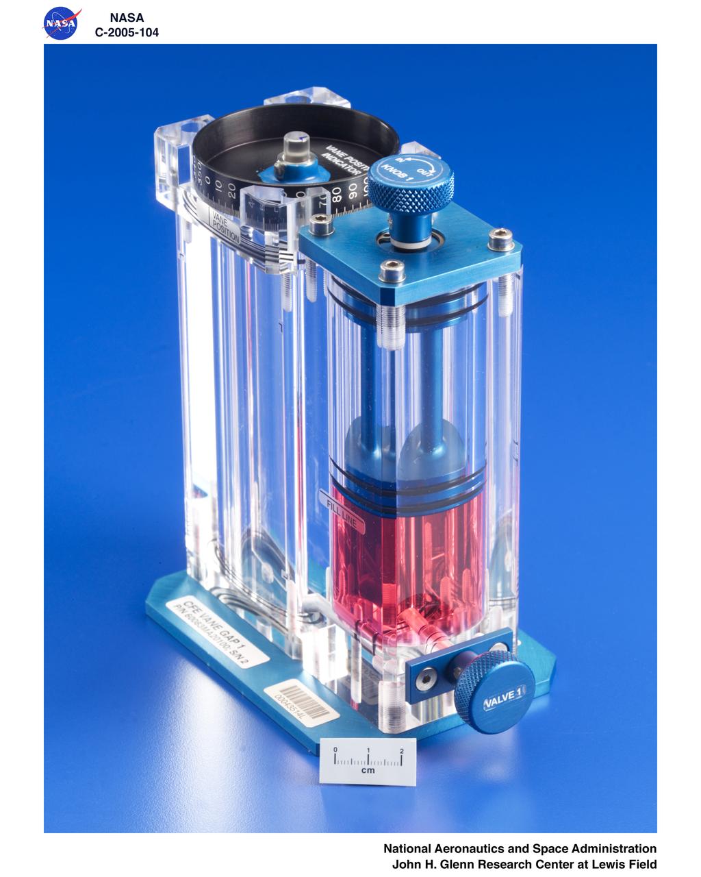
Capillary Flow Experiment (CFE) - Vane Gap 1, Flight Hardware, P/N 60083MA20100; S/N 2
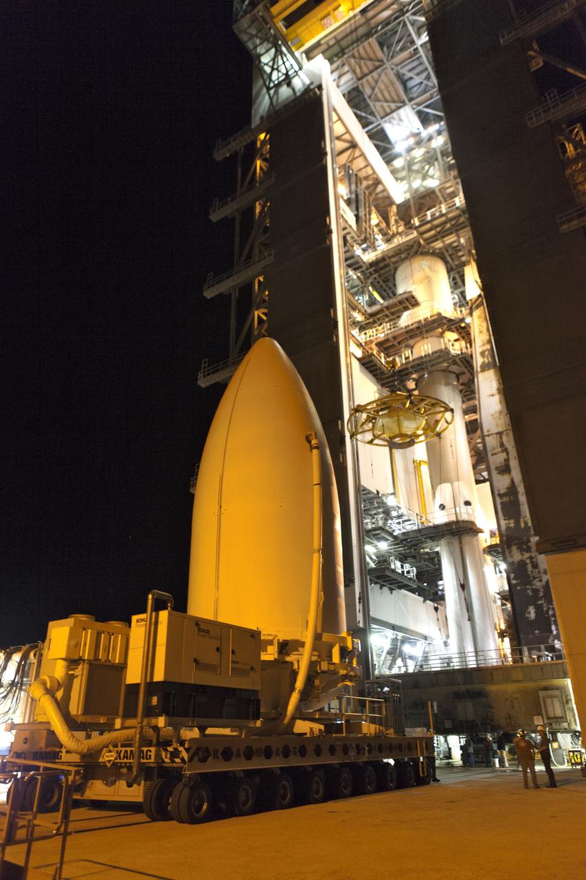
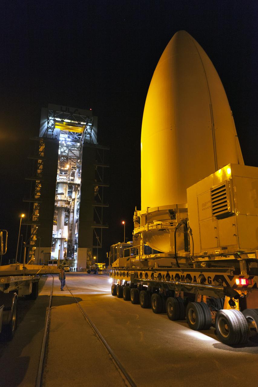
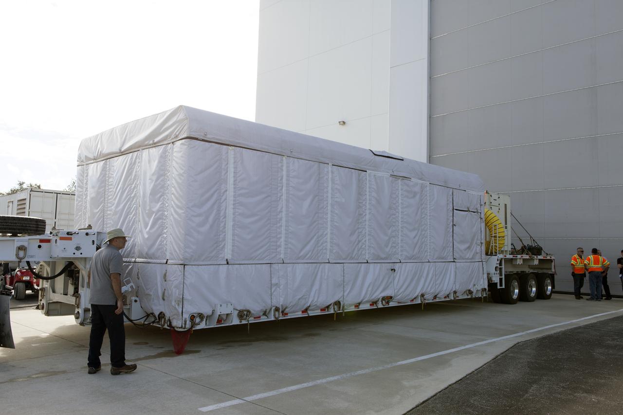
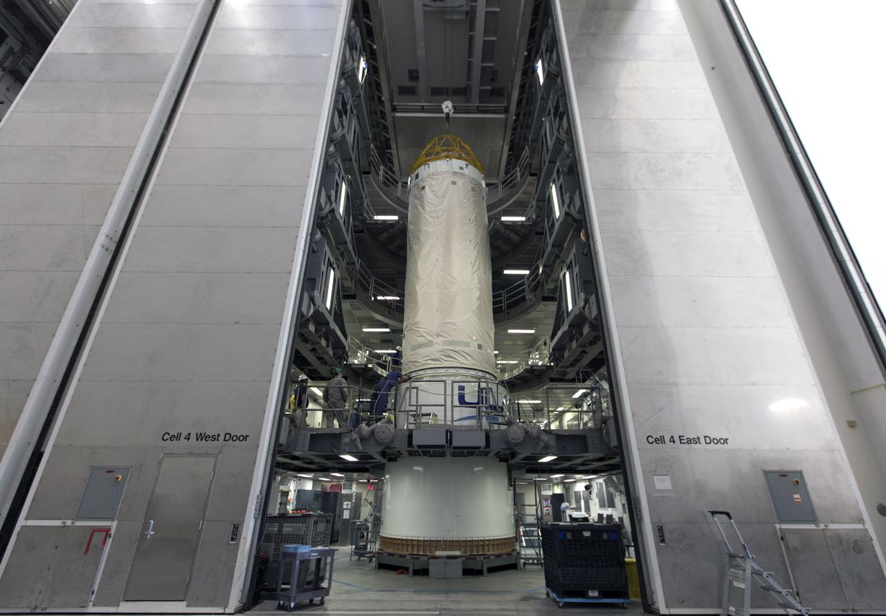
The payload fairing containing NOAA's Geostationary Operational Environmental Satellite-S (GOES-S), secured on a transporter, arrives at the United Launch Alliance (ULA) Vertical Integration Facility at Space Launch Complex 41 at Cape Canaveral Air Force Station in Florida. The payload fairing will be lifted and mated to the ULA Atlas V rocket. GOES-S is the second in a series of four advanced geostationary weather satellites. GOES-S is slated to launch aboard the ULA Atlas V on March 1.
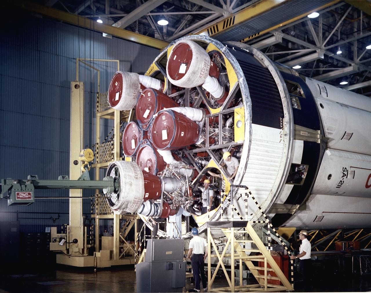
S-IB-211, the flight version of the Saturn IB launch vehicle's first (S-IVB) stage, arrives at Marshall Space Flight Center's (MSFC's) S-IB static test stand. Between December 1967 and April 1968, the stage would undergo seven static test firings. The S-IB, developed by the MSFC and built by the Chrysler Corporation at the Michoud Assembly Facility near New Orleans, Louisiana, utilized eight H-1 engines and each produced 200,000 pounds of thrust.
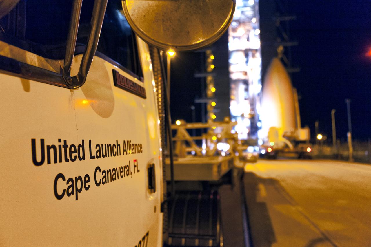
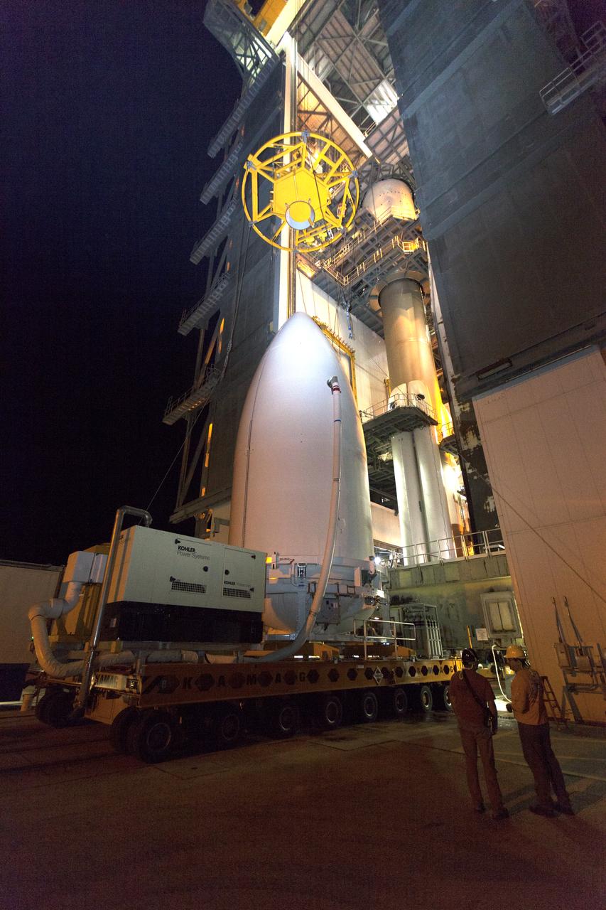
The payload fairing containing NOAA's Geostationary Operational Environmental Satellite-S (GOES-S), secured on a transporter, arrives at the United Launch Alliance (ULA) Vertical Integration Facility at Space Launch Complex 41 at Cape Canaveral Air Force Station in Florida. The payload fairing will be lifted and mated to the ULA Atlas V rocket. GOES-S is the second in a series of four advanced geostationary weather satellites. GOES-S is slated to launch aboard the ULA Atlas V on March 1.
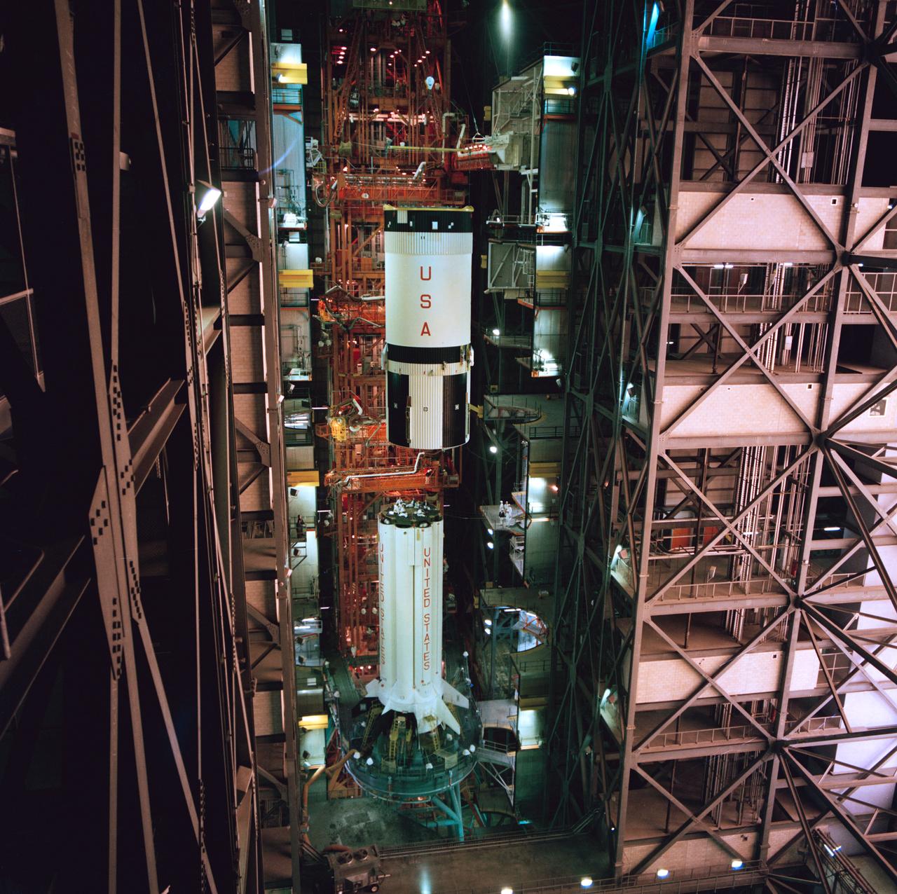
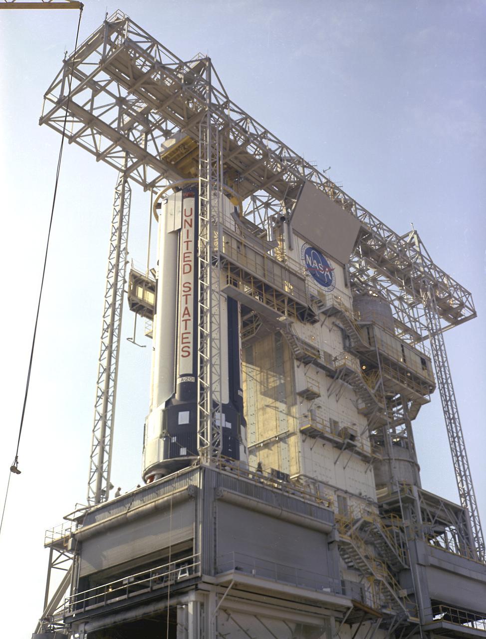
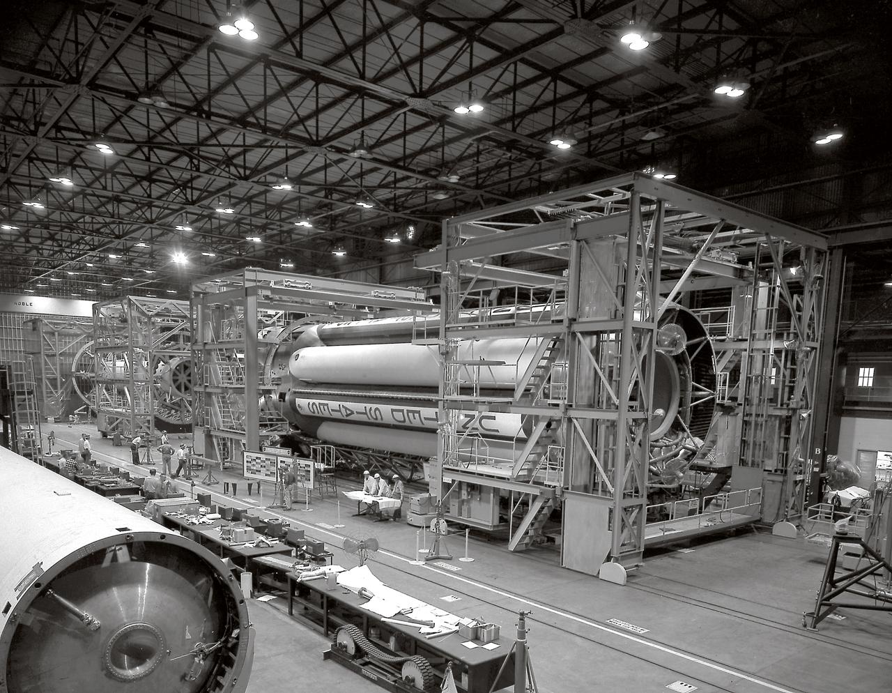
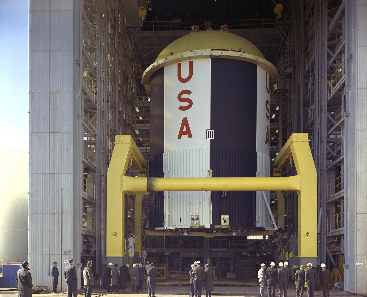
S75-20909 (January 1975) --- A high-angle view of the high-bay area in the Vehicle Assembly Building at the Kennedy Space Center showing the second (S-IVB) stage of the Saturn 1-B launch vehicle for the joint U.S.-USSR Apollo-Soyuz Test Project mission being hoisted into position for mating atop the first (S-1B) stage. The major components of the American ASTP space vehicle will be the S-1B stage, the S-IVB stage, and a payload consisting of a Command/Service Module and a Docking Module.
The payload fairing containing NOAA's Geostationary Operational Environmental Satellite-S (GOES-S), secured on a transporter, arrives at the United Launch Alliance (ULA) Vertical Integration Facility at Space Launch Complex 41 at Cape Canaveral Air Force Station in Florida. The payload fairing will be lifted and mated to the ULA Atlas V rocket. GOES-S is the second in a series of four advanced geostationary weather satellites. GOES-S is slated to launch aboard the ULA Atlas V on March 1.
S-IB-211, the flight version of the Saturn IB launch vehicle's (S-IVB) first stage, after installation at the Marshall Space Flight Center's (MSFC's) S-IB static test stand. Between December 1967 and April 1968, the stage would undergo seven static test firings. The S-IB, developed by the MSFC and built by the Chrysler Corporation at the Michoud Assembly Facility near New Orleans, Louisiana, utilized eight H-1 engines and each produced 200,000 pounds of thrust.
The payload fairing containing NOAA's Geostationary Operational Environmental Satellite-S (GOES-S), secured on a transporter, arrives at the United Launch Alliance (ULA) Vertical Integration Facility at Space Launch Complex 41 at Cape Canaveral Air Force Station in Florida. The payload fairing will be lifted and mated to the ULA Atlas V rocket. GOES-S is the second in a series of four advanced geostationary weather satellites. GOES-S is slated to launch aboard the ULA Atlas V on March 1.
Progress in the Saturn program, depicted below, was described by Dr. Wernher von Braun, Marshall Space Flight Center (MSFC) Director, in an appearance before the Senate Committee of Aeronautical and Space Sciences. "The flight configuration of the giant three-stage Saturn C-1 rocket (later called Saturn I Block I) is seen in the Fabrication and Assembly Engineering Division at MSFC. Dwarfed by the 180-foot C-1 are a Juno II rocket (left rear) and a Mercury-Redstone rocket (front foreground). The C-1 (first version of the Saturn rocket) is composed of an S-1 first stage or booster (rear), powered by eight H-1 engines having a thrust of 1,500,000 pounds, followed by a dummy S-IV second stage and a dummy S-V third stage. The "live" S-IV for later flights, under development by Douglas Aircraft Co., will be powered by four Pratt Whitney LR-119 engines having 17,500,000 pounds thrust each. The live S-V, under development by Convair Division of General Dynamics Corp., will use two LR-119 engines. With all three stages live, the C-1 will be capable of placing 19,000 pounds into a 300-mile Earth orbit, sending 5,000 pounds to escape velocity, or lofting 2,500 pounds to Mars or Venus. The second version Saturn C-2 (later called Saturn 1 Block II) would double these capabilities. Early C-1 flights will employ a live S-1 with dummy upper stages. The first such flight is scheduled late this year."
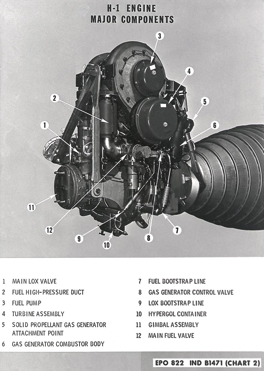
H-1 engine major components with callouts (chart 1). The H-1 engine was used in a cluster of eight on the the first stage of Saturn I (S-I stage) and Saturn IB (S-IB stage). The engines were arranged in a double pattern: four engines, located inboard, were fixed in a square pattern around the stage axis, while the remaining four engines were located outboard in a larger square pattern and each outer engine was gimbaled. Each H-1 engine had a thrust of 188,000 pounds for a combined thrust of over 1,500,000 pounds.
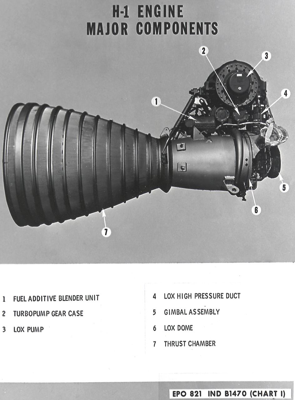
H-1 Engine major components with callouts (chart 1): The H-1 engine was used in a cluster of eight on the the first stage of Saturn I (S-I stage) and Saturn IB (S-IB stage). The engines were arranged in a double pattern: four engines, located inboard, were fixed in a square pattern around the stage axis, while the remaining four engines were located outboard in a larger square pattern and each outer engine was gimbaled. Each H-1 engine had a thrust of 188,000 pounds for a combined thrust of over 1,500,000 pounds.
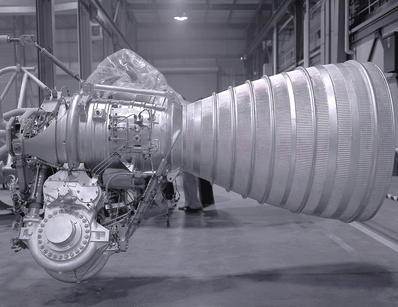
A Cluster of eight H-1 engines were used to thrust the first stage of Saturn I (S-I stage) and Saturn IB (S-IB stage). The engines were arranged in a double pattern. Four engines, located inboard, were fixed in a square pattern around the stage axis, while the remaining four engines were located outboard in a larger square pattern and each outer engine was gimbaled. Each H-1 engine, fueled with liquid oxygen (LOX) and kerosene (RP-1), had a thrust of 188,000 pound each for a combined thrust of over 1,500,000 pounds. The H-1 engine was developed under the direction of Marshall Space Flight Center (MSFC).
A Cluster of eight H-1 engines were used to thrust the first stage of Saturn I (S-I stage) and Saturn IB (S-IB stage). The engines were arranged in a double pattern. Four engines, located inboard, were fixed in a square pattern around the stage axis, while the remaining four engines were located outboard in a larger square pattern and each outer engine was gimbaled. The H-1 engine, fueled with liquid oxygen (LOX) and kerosene (RP-1), had a thrust of 188,000 pound each for a combined thrust of over 1,500,000 pounds. Each H-1 engine was developed under the direction of Marshall Space Flight Center (MSFC).
This photograph depicts Marshall Space Flight Center employees, James Reagin, machinist (top); Floyd McGinnis, machinist; and Ernest Davis, experimental test mechanic (foreground), working on a mock up of the S-IC thrust structure. The S-IC stage is the first stage, or booster, of the 364-foot long Saturn V rocket that ultimately took astronauts to the Moon. The S-IC stage, burned over 15 tons of propellant per second during its 2.5 minutes of operation to take the vehicle to a height of about 36 miles and to a speed of about 6,000 miles per hour. The stage was 138 feet long and 33 feet in diameter. Operating at maximum power, all five of the engines produced 7,500,000 pounds of thrust.
The Saturn Project was approved on January 18, 1960, as a program of the highest national priority. The formal test program to prove out the clustered-booster concept was well underway at Redstone Arsenal. This photograph depicts a mockup of the Saturn booster (S-I stage) being installed in the Army Ballistic Missile Agency (ABMA) test stand, on January 19, 1960, to check mating of the booster and stand and servicing methods.
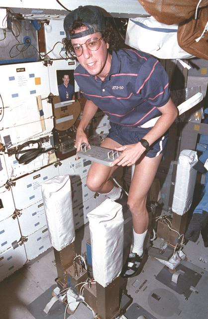
Onboard Space Shuttle Columbia (STS-50) in the United States Microgravity Laboratory (USML-1) mission specialist Ellen S. Baker is hard at work.
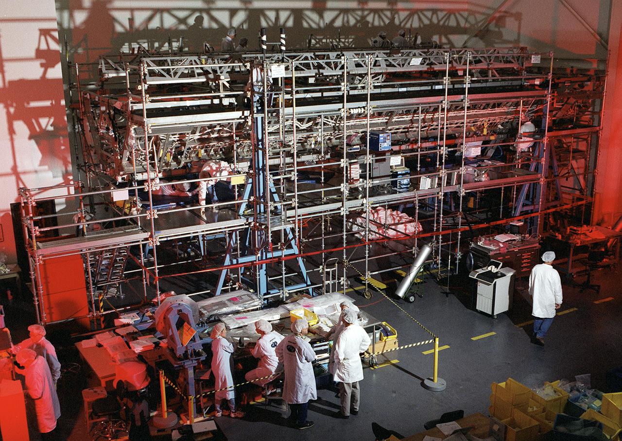
Boeing Company technicians assemble the S-1 truss (starboard side truss) for the International Space Station at the Marshall Space Flight Center.
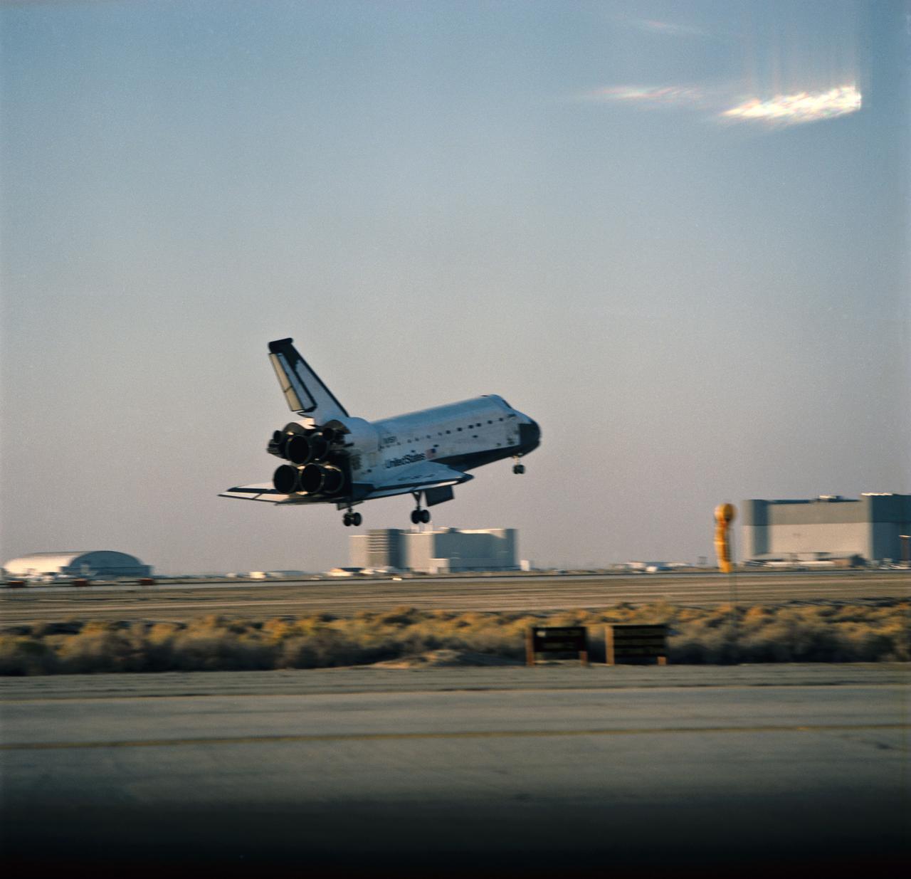
STS58-S-126 (1 Nov 1993) --- The Space Shuttle Columbia is about to touch down on the runway at Edwards Air Force Base (EAFB) in California. The landing, which occurred at 7:06 a.m. (PST), November 1, 1993, completed a two week mission in space devoted to medical research. Onboard the spacecraft were astronauts John E. Blaha, Richard A. Searfoss, Rhea Seddon, Shannon W. Lucid, David A. Wolf and William S. McArthur along with payload specialist Martin J. Fettman, DVM.
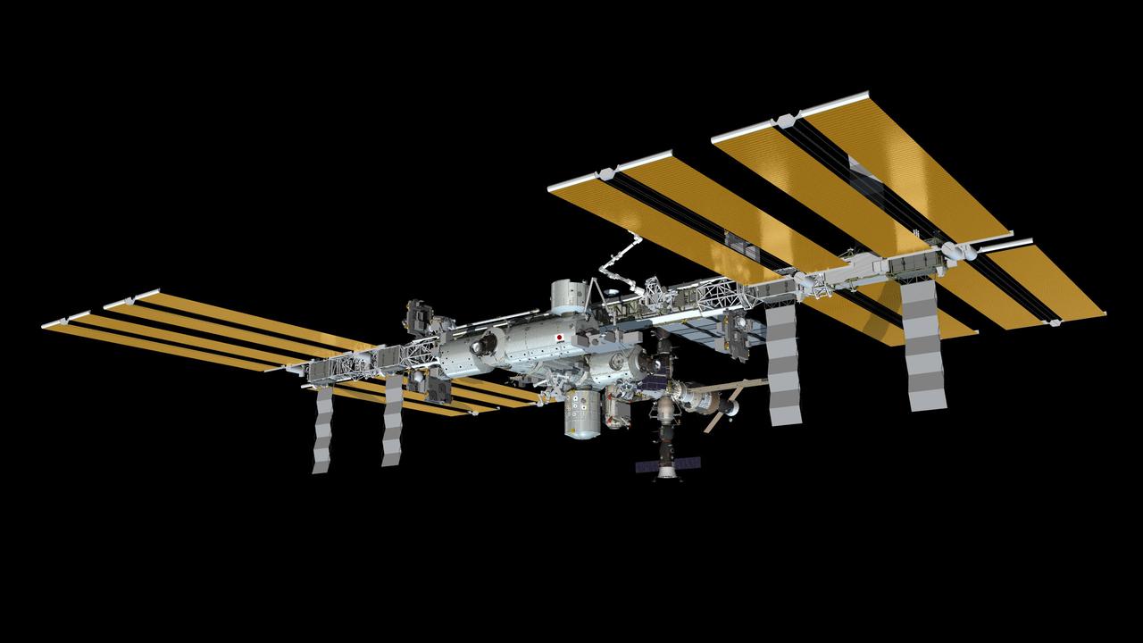
JSC2013-E-090733 (November 2013) --- Computer-generated artist?s rendering of the International Space Station as of Nov. 1, 2013. Soyuz 35 (TMA-09M) undocks from the Rassvet Mini-Research Module 1 (MRM1) and relocates to the Zvezda Service Module?s aft port. Soyuz 36 (TMA-10M) is docked to Poisk Mini-Research Module 2 (MRM2). Progress 52 resupply vehicle is linked to the Pirs Docking Compartment. Photo credit: NASA
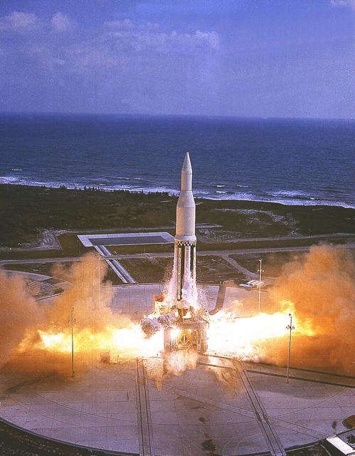
The Marshall Space Flight Center's first Saturn I vehicle, SA-1, lifts off from Cape Canaveral, Florida, on October 27, 1961. This early configuration, Saturn I Block I, 162 feet tall and weighing 460 tons, consisted of the eight H-1 engines S-I stage and the dummy second stage (S-IV stage).
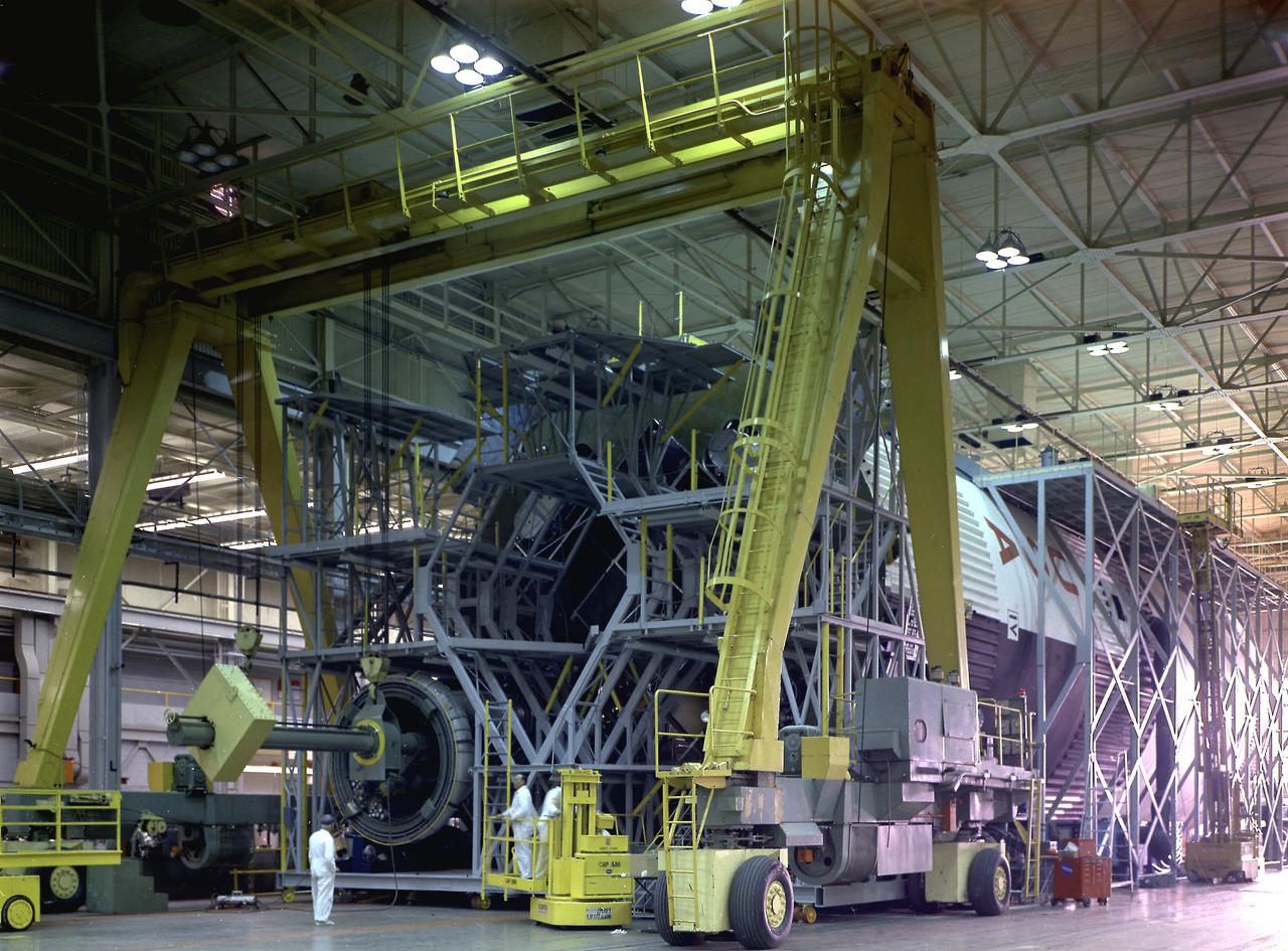
The fuel tank assembly of the Saturn V S-IC (first) stage supported with the aid of a C frame on the transporter was readied to be transported to the Marshall Space Flight Center, building 4705. The fuel tank carried kerosene (RP-1) as its fuel. The S-IC stage utilized five F-1 engines that used kerosene and liquid oxygen as propellant and each engine provided 1,500,000 pounds of thrust. This stage lifted the entire vehicle and Apollo spacecraft from the launch pad.
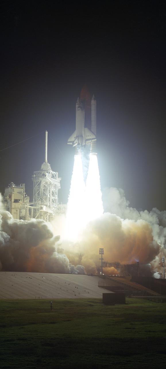
STS035-S-021 (2 Dec 1990) --- The Space Shuttle Columbia lifts off Launch Pad 39B at 1:49 a.m. (EST), Dec. 2, 1990. Primary payload onboard is the Astro-1 astronomical laboratory, headed for a ten-day fight dedicated to the single discipline of astrophysics. Crewmembers are five astronauts--Vance D. Brand, Guy S. Gardner, John M. (Mike) Lounge, Jeffrey A. Hoffman and Robert A.R. Parker--and two payload specialists--Samuel T. Durrance and Ronald A. Parise.
This photograph shows the fuel tank assembly for the Saturn V S-IC (first) stage being transported to the Marshall Space Flight Center, building 4705 for mating to the liquid oxygen (LOX) tank. The fuel tank carried kerosene (RP-1) as its fuel. The S-IC stage used five F-1 engines, that used kerosene and liquid oxygen as propellant and each engine provided 1,500,000 pounds of thrust. This stage lifted the entire vehicle and Apollo spacecraft from the launch pad.
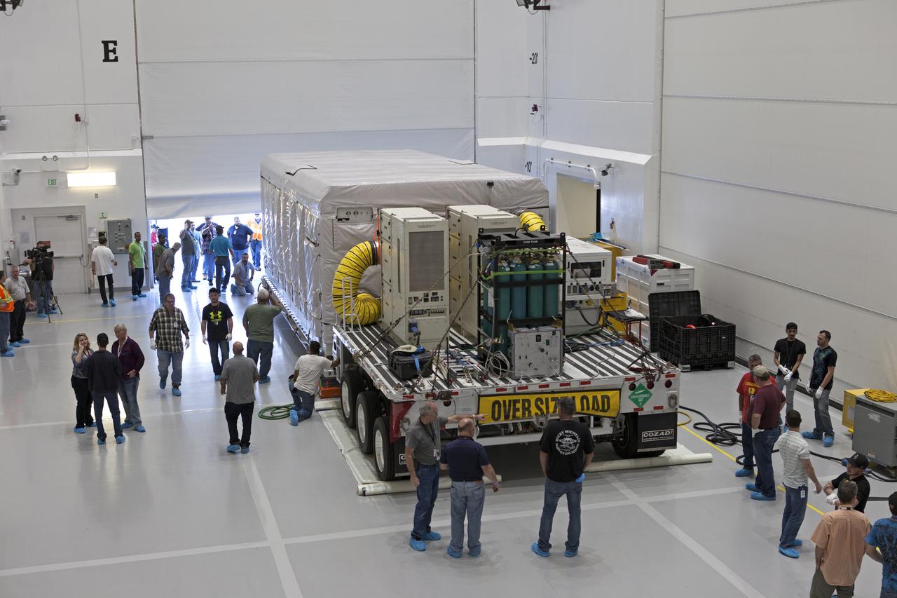
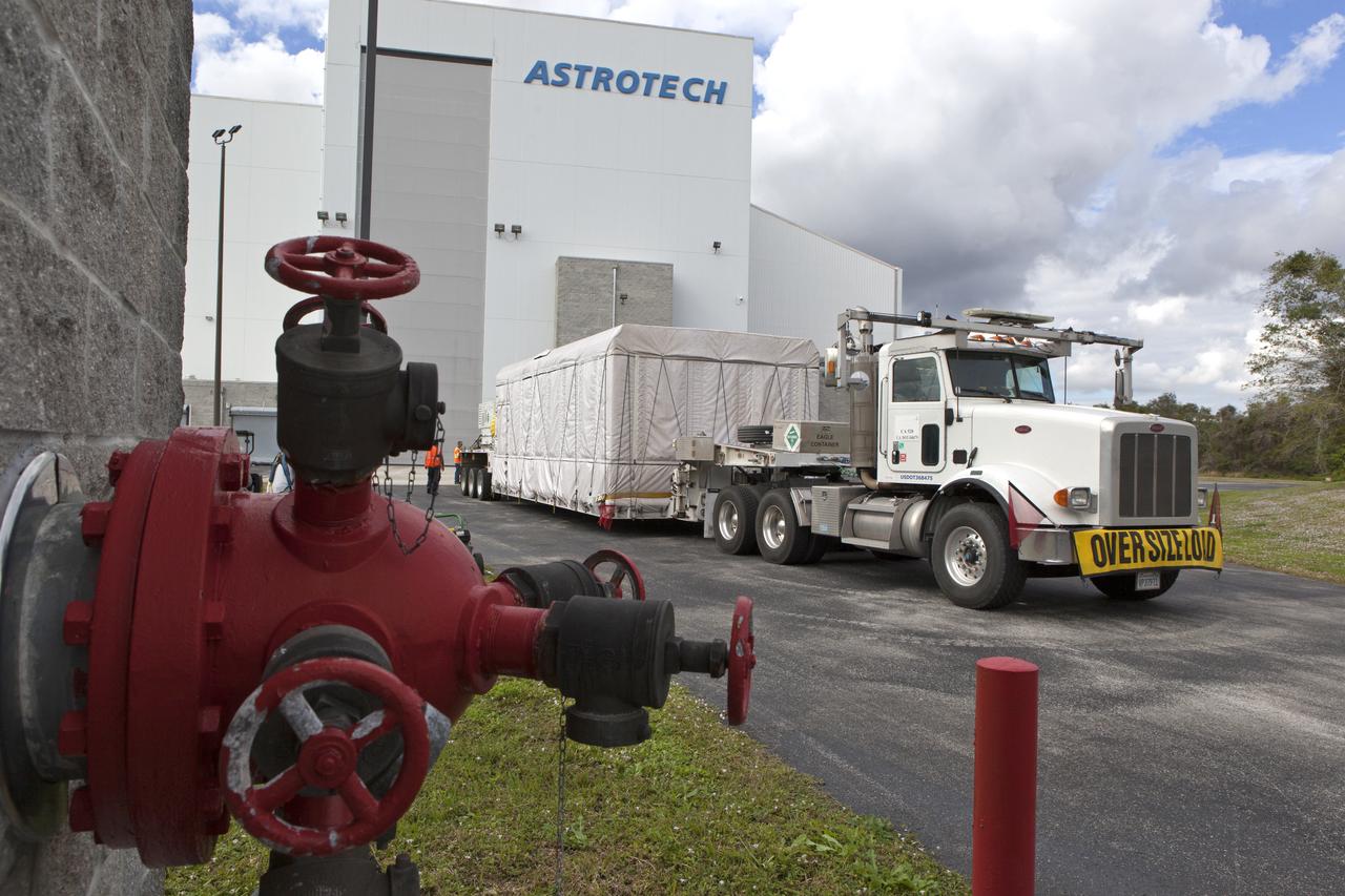
NOAA's Geostationary Operation Environmental Satellite-S (GOES-S) arrives at Astrotech Space Operations in Titusville, Florida, to prepare it for launch. The facility is located near NASA's Kennedy Space Center. GOES-S is the second in a series of four advanced geostationary weather satellites. The GOES-R series - consisting of the GOES-R, GOES-S, GOES-T and GOES-U spacecraft - will significantly improve the detection and observation of environmental phenomena that directly affect public safety, protection of property and the nation's economic health and prosperity. GOES-S is slated to launch March 1, 2018 aboard a United Launch Alliance Atlas V rocket from Cape Canaveral Air Force Station in Florida.
NOAA's Geostationary Operation Environmental Satellite-S (GOES-S) arrives inside Astrotech Space Operations in Titusville, Florida, to prepare it for launch. The facility is located near NASA's Kennedy Space Center. GOES-S is the second in a series of four advanced geostationary weather satellites. The GOES-R series - consisting of the GOES-R, GOES-S, GOES-T and GOES-U spacecraft - will significantly improve the detection and observation of environmental phenomena that directly affect public safety, protection of property and the nation's economic health and prosperity. GOES-S is slated to launch March 1, 2018 aboard a United Launch Alliance Atlas V rocket from Cape Canaveral Air Force Station in Florida.
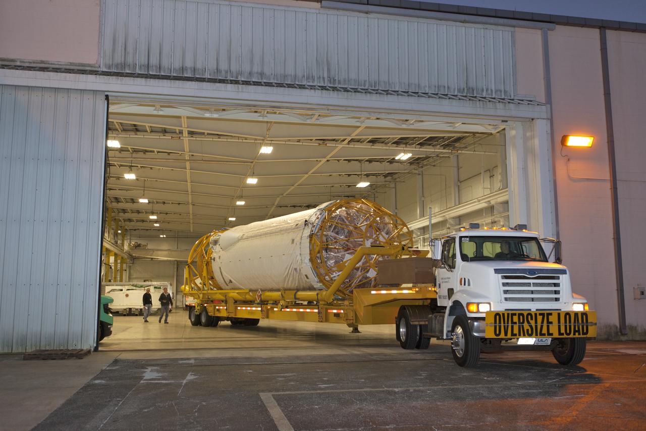
The Centaur upper stage that will help launch NOAA's Geostationary Operational Environmental Satellite-S, or GOES-S, is being transported from the Atlas Spaceflight Operations Center at Cape Canaveral Air Force Station to the Delta Operations Center for further processing. GOES-S is the second in a series of four advanced geostationary weather satellites. The GOES-R series - consisting of the GOES-R, GOES-S, GOES-T and GOES-U spacecraft - will significantly improve the detection and observation of environmental phenomena that directly affect public safety, protection of property and the nation's economic health and prosperity. GOES-S is slated to launch March 1, 2018 aboard a United Launch Alliance Atlas V rocket.
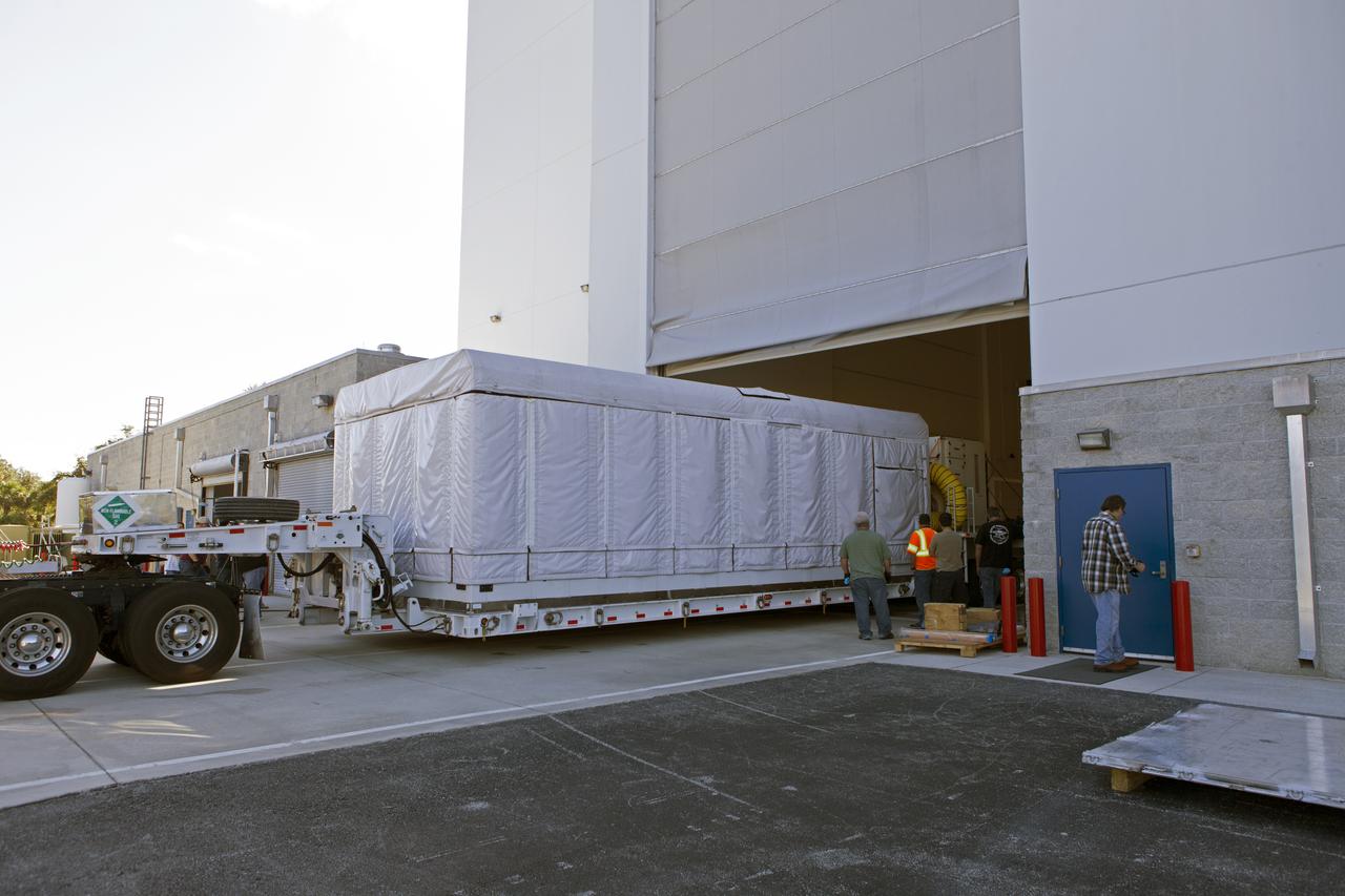
NOAA's Geostationary Operation Environmental Satellite-S (GOES-S) arrives at Astrotech Space Operations in Titusville, Florida, to prepare it for launch. The facility is located near NASA's Kennedy Space Center. GOES-S is the second in a series of four advanced geostationary weather satellites. The GOES-R series - consisting of the GOES-R, GOES-S, GOES-T and GOES-U spacecraft - will significantly improve the detection and observation of environmental phenomena that directly affect public safety, protection of property and the nation's economic health and prosperity. GOES-S is slated to launch March 1, 2018 aboard a United Launch Alliance Atlas V rocket from Cape Canaveral Air Force Station in Florida.
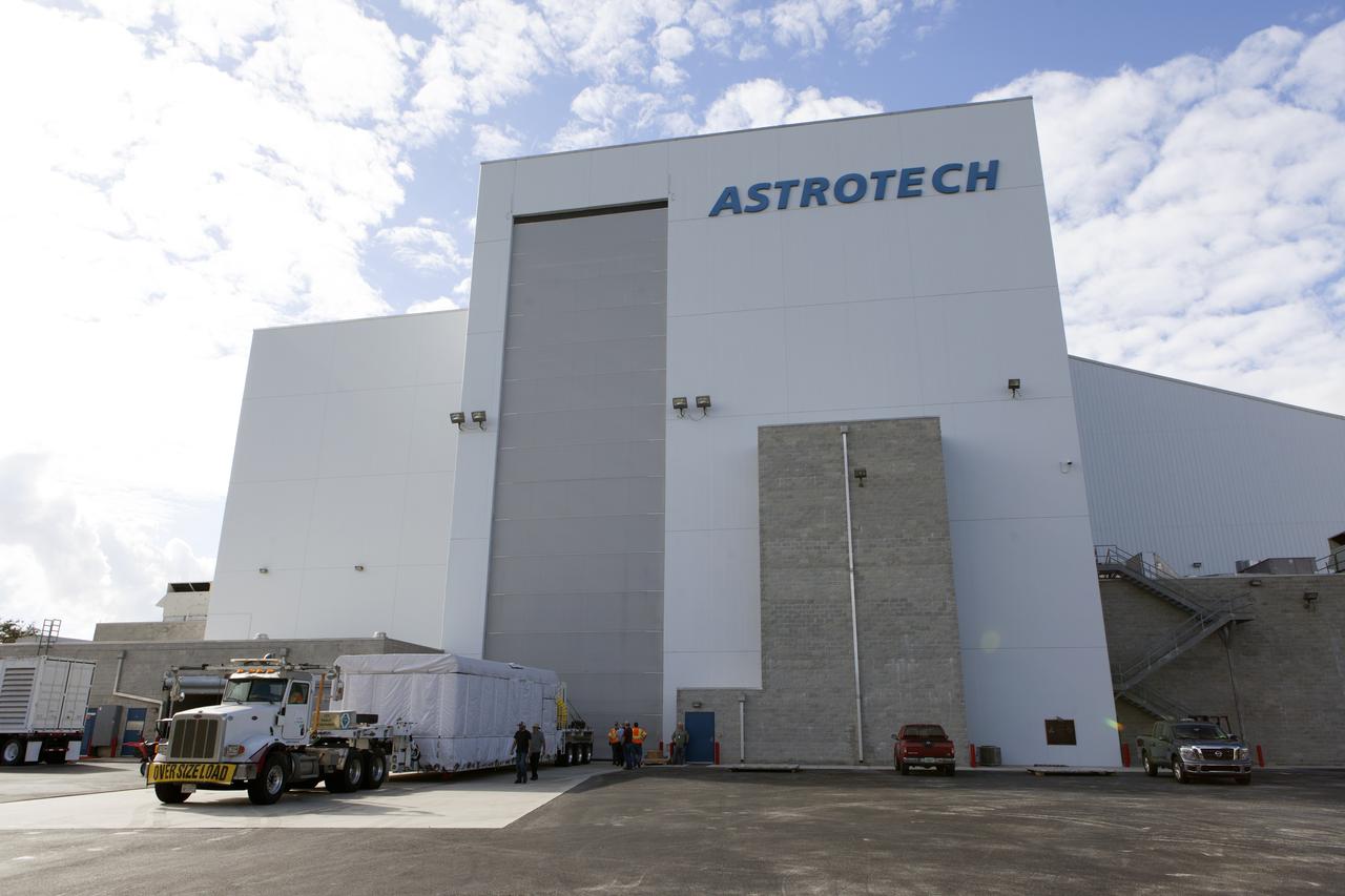
NOAA's Geostationary Operation Environmental Satellite-S (GOES-S) arrives at Astrotech Space Operations in Titusville, Florida, to prepare it for launch. The facility is located near NASA's Kennedy Space Center. GOES-S is the second in a series of four advanced geostationary weather satellites. The GOES-R series - consisting of the GOES-R, GOES-S, GOES-T and GOES-U spacecraft - will significantly improve the detection and observation of environmental phenomena that directly affect public safety, protection of property and the nation's economic health and prosperity. GOES-S is slated to launch March 1, 2018 aboard a United Launch Alliance Atlas V rocket from Cape Canaveral Air Force Station in Florida.
NOAA's Geostationary Operation Environmental Satellite-S (GOES-S) arrives at Astrotech Space Operations in Titusville, Florida, to prepare it for launch. The facility is located near NASA's Kennedy Space Center. GOES-S is the second in a series of four advanced geostationary weather satellites. The GOES-R series - consisting of the GOES-R, GOES-S, GOES-T and GOES-U spacecraft - will significantly improve the detection and observation of environmental phenomena that directly affect public safety, protection of property and the nation's economic health and prosperity. GOES-S is slated to launch March 1, 2018 aboard a United Launch Alliance Atlas V rocket from Cape Canaveral Air Force Station in Florida.
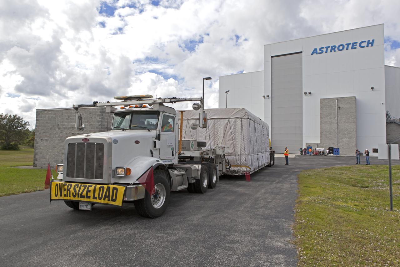
NOAA's Geostationary Operation Environmental Satellite-S (GOES-S) arrives at Astrotech Space Operations in Titusville, Florida, to prepare it for launch. The facility is located near NASA's Kennedy Space Center. GOES-S is the second in a series of four advanced geostationary weather satellites. The GOES-R series - consisting of the GOES-R, GOES-S, GOES-T and GOES-U spacecraft - will significantly improve the detection and observation of environmental phenomena that directly affect public safety, protection of property and the nation's economic health and prosperity. GOES-S is slated to launch March 1, 2018 aboard a United Launch Alliance Atlas V rocket from Cape Canaveral Air Force Station in Florida.
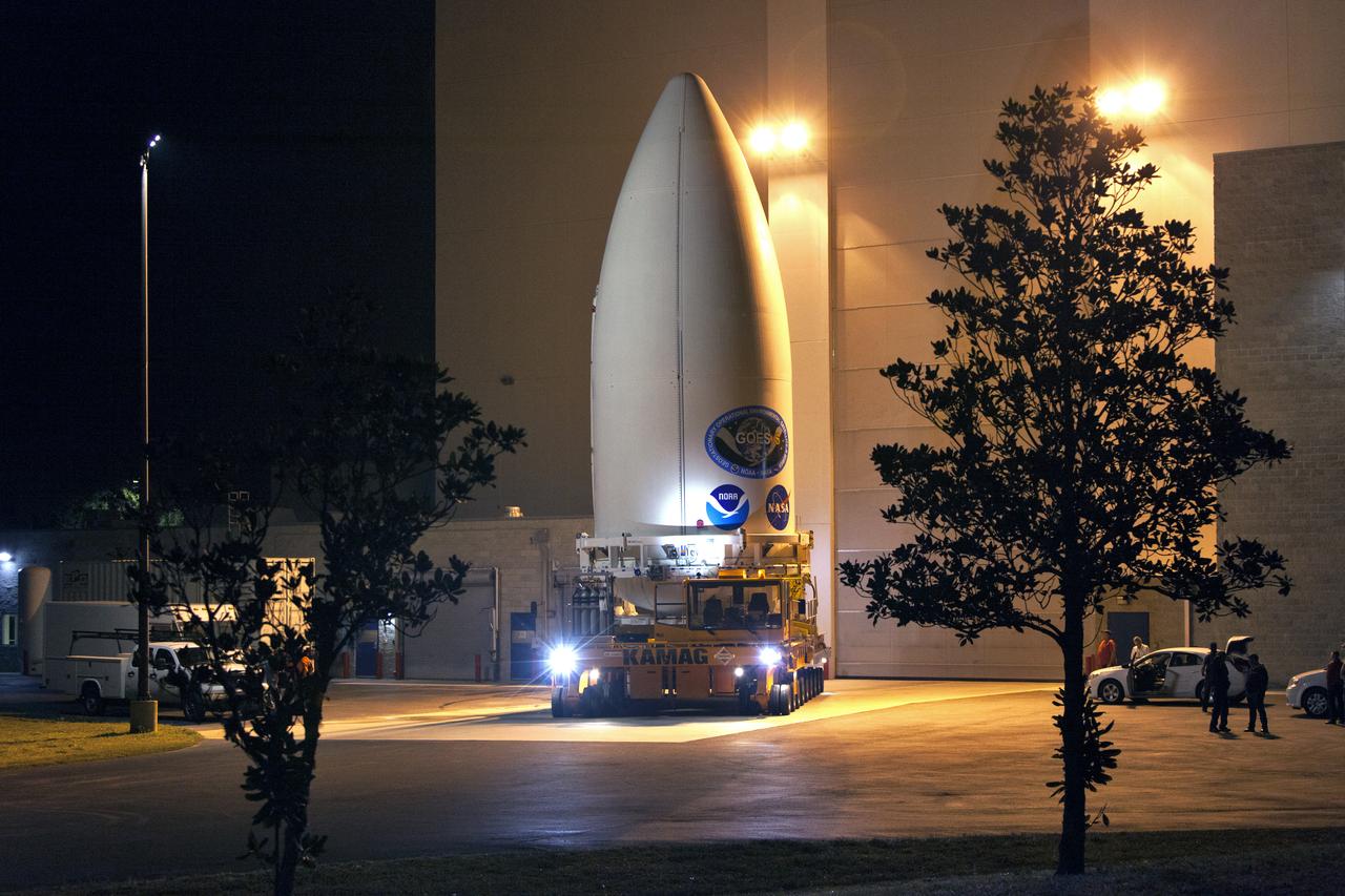
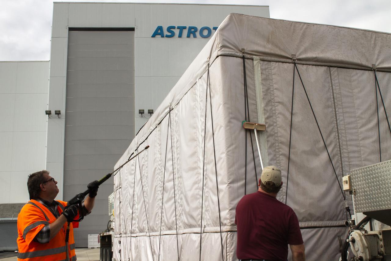
The payload fairing containing NOAA's Geostationary Operational Environmental Satellite-S (GOES-S), secured on a transporter, departs the Astrotech Space Operations facility in Titusville, Florida. GOES-S will be transported to the United Launch Alliance (ULA) Vertical Integration Facility at Space Launch Complex 41 at Cape Canaveral Air Force Station in Florida. The payload fairing will be lifted and mated to the ULA Atlas V rocket. GOES-S is the second in a series of four advanced geostationary weather satellites. GOES-S is slated to launch aboard the ULA Atlas V on March 1.
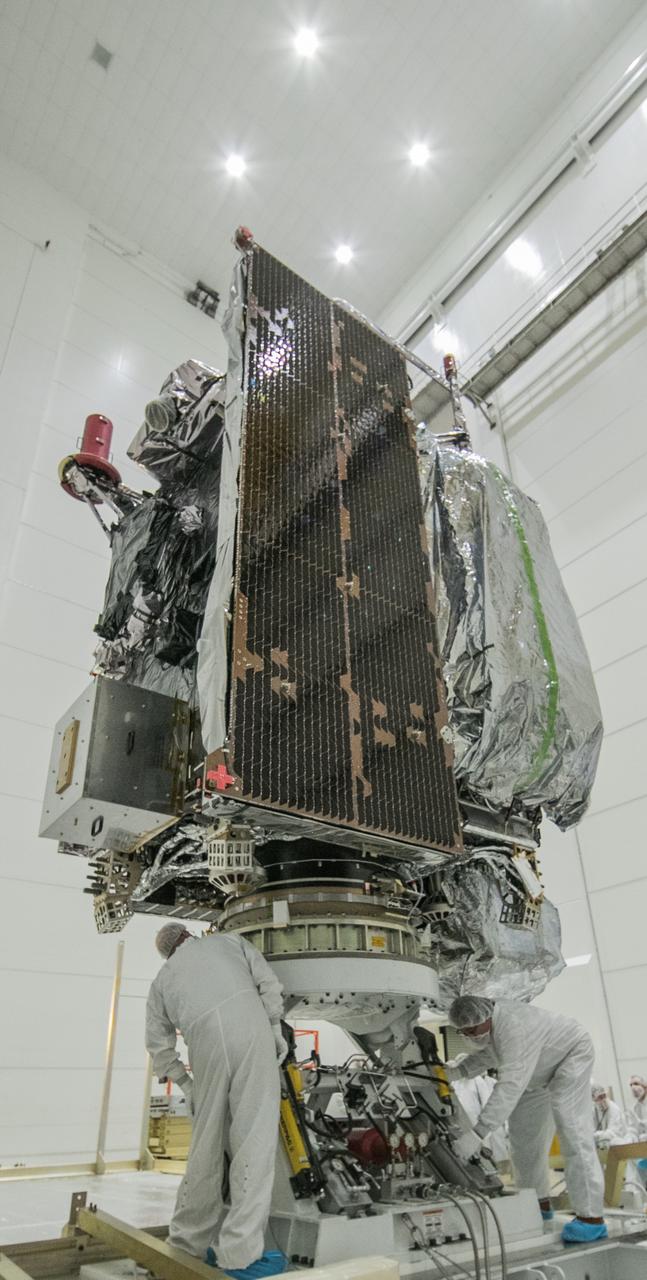
At Astrotech Space Operations in Titusville, Florida, technicians and engineers inspect NOAA's Geostationary Operation Environmental Satellite-S (GOES-S) after removal from its shipping container. GOES-S is the second in a series of four advanced geostationary weather satellites. The GOES-R series - consisting of the GOES-R, GOES-S, GOES-T and GOES-U spacecraft - will significantly improve the detection and observation of environmental phenomena that directly affect public safety, protection of property and the nation's economic health and prosperity. GOES-S is slated to launch March 1, 2018 aboard a United Launch Alliance Atlas V rocket from Cape Canaveral Air Force Station in Florida.
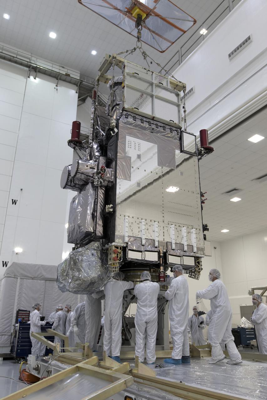
At Astrotech Space Operations in Titusville, Florida, technicians and engineers inspect NOAA's Geostationary Operational Environmental Satellite-S (GOES-S). The facility is located near NASA's Kennedy Space Center. GOES-S is the second in a series of four advanced geostationary weather satellites. The GOES-R series - consisting of the GOES-R, GOES-S, GOES-T and GOES-U spacecraft - will significantly improve the detection and observation of environmental phenomena that directly affect public safety, protection of property and the nation's economic health and prosperity. GOES-S is slated to launch March 1, 2018 aboard a United Launch Alliance Atlas V rocket from Cape Canaveral Air Force Station in Florida.
The Centaur upper stage that will help launch NOAA's Geostationary Operational Environmental Satellite-S, or GOES-S, has been positioned in at test cell inside the Delta Operations Center at Cape Canaveral Air Force Station for further processing. GOES-S is the second in a series of four advanced geostationary weather satellites. The GOES-R series - consisting of the GOES-R, GOES-S, GOES-T and GOES-U spacecraft - will significantly improve the detection and observation of environmental phenomena that directly affect public safety, protection of property and the nation's economic health and prosperity. GOES-S is slated to launch March 1, 2018 aboard a United Launch Alliance Atlas V rocket.
NOAA's Geostationary Operation Environmental Satellite-S (GOES-S) arrives at Astrotech Space Operations in Titusville, Florida, to prepare it for launch. The facility is located near NASA's Kennedy Space Center. GOES-S is the second in a series of four advanced geostationary weather satellites. The GOES-R series - consisting of the GOES-R, GOES-S, GOES-T and GOES-U spacecraft - will significantly improve the detection and observation of environmental phenomena that directly affect public safety, protection of property and the nation's economic health and prosperity. GOES-S is slated to launch March 1, 2018 aboard a United Launch Alliance Atlas V rocket from Cape Canaveral Air Force Station in Florida.
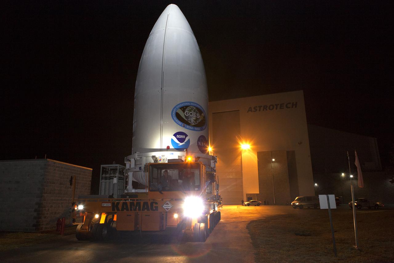
The payload fairing containing NOAA's Geostationary Operational Environmental Satellite-S (GOES-S), secured on a transporter, departs the Astrotech Space Operations facility in Titusville, Florida. GOES-S will be transported to the United Launch Alliance (ULA) Vertical Integration Facility at Space Launch Complex 41 at Cape Canaveral Air Force Station in Florida. The payload fairing will be lifted and mated to the ULA Atlas V rocket. GOES-S is the second in a series of four advanced geostationary weather satellites. GOES-S is slated to launch aboard the ULA Atlas V on March 1.
At Astrotech Space Operations in Titusville, Florida, technicians and engineers remove NOAA's Geostationary Operation Environmental Satellite-S (GOES-S) from its shipping container. GOES-S is the second in a series of four advanced geostationary weather satellites. The GOES-R series - consisting of the GOES-R, GOES-S, GOES-T and GOES-U spacecraft - will significantly improve the detection and observation of environmental phenomena that directly affect public safety, protection of property and the nation's economic health and prosperity. GOES-S is slated to launch March 1, 2018 aboard a United Launch Alliance Atlas V rocket from Cape Canaveral Air Force Station in Florida.