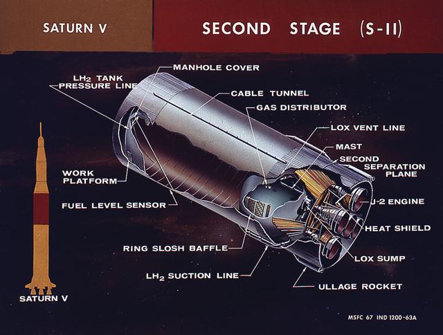
This cutaway illustration shows the Saturn V S-II (second) stage with callouts of major components. When the Saturn V first stage burns out and drops away, power for the Saturn was provided by the S-II (second) stage with five J-2 engines which produced a total of 1,150,000 pounds of thrust. Four outer engines are placed in a square pattern with gimbaling capability for control and guidance, with the fifth engine fixed rigidly in the center.
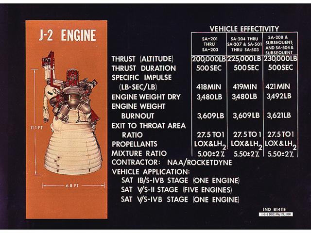
This chart is an illustration of J-2 Engine characteristics. A cluster of five J-2 engines powered the Saturn V S-II (second) stage with each engine providing a thrust of 200,000 pounds. A single J-2 engine powered the S-IVB stage, the Saturn IB second stage, and the Saturn V third stage. The engine was uprated to provide 230,000 pounds of thrust for the fourth Apollo Saturn V flight and subsequent missions. Burning liquid hydrogen as fuel and using liquid oxygen as the oxidizer, the cluster of five J-2 engines for the S-II stage burned over one ton of propellant per second, during about 6 1/2 minutes of operation, to take the vehicle to an altitude of about 108 miles and a speed of near orbital velocity, about 17,400 miles per hour.
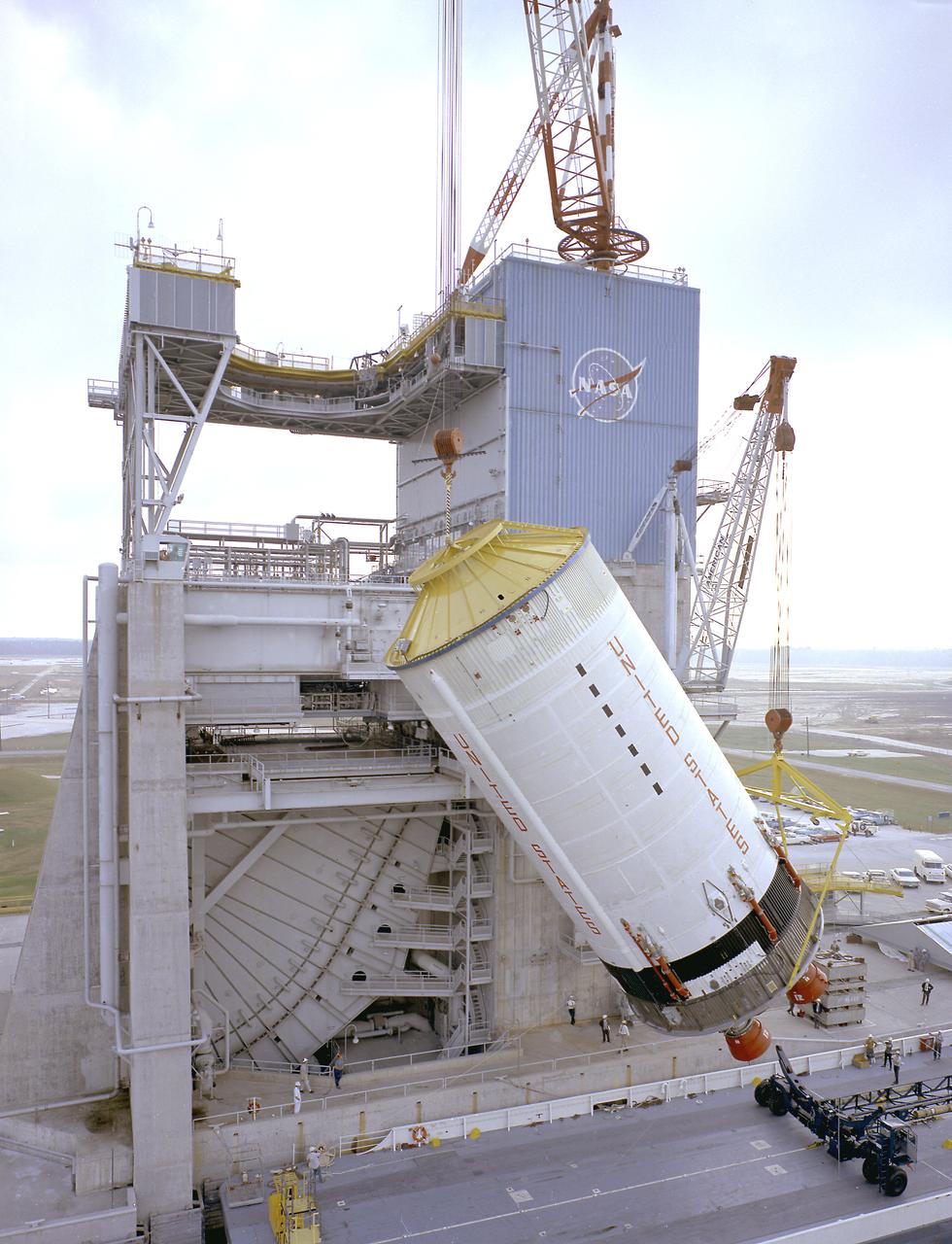
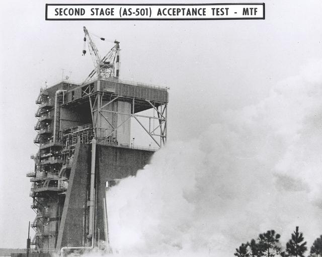
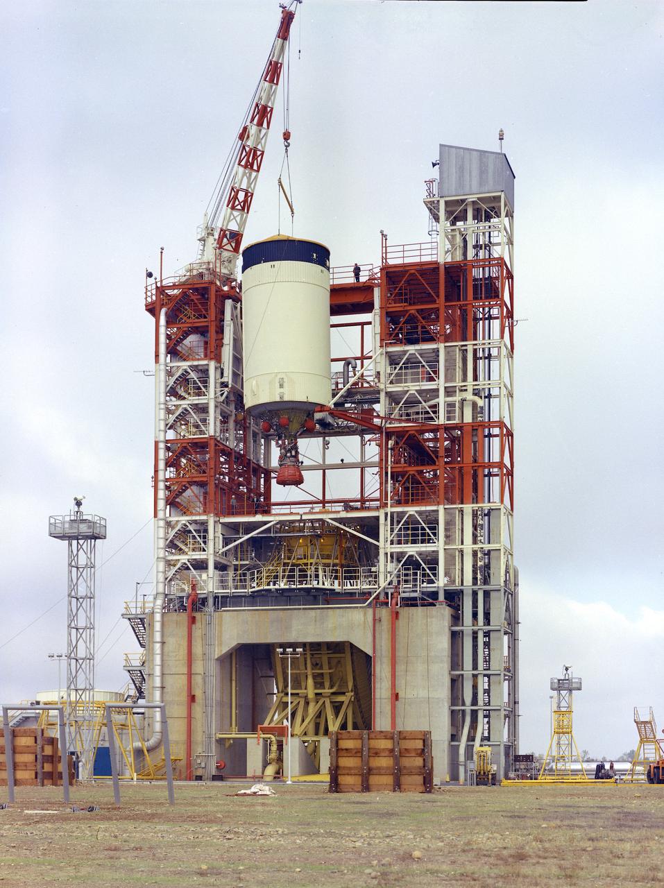
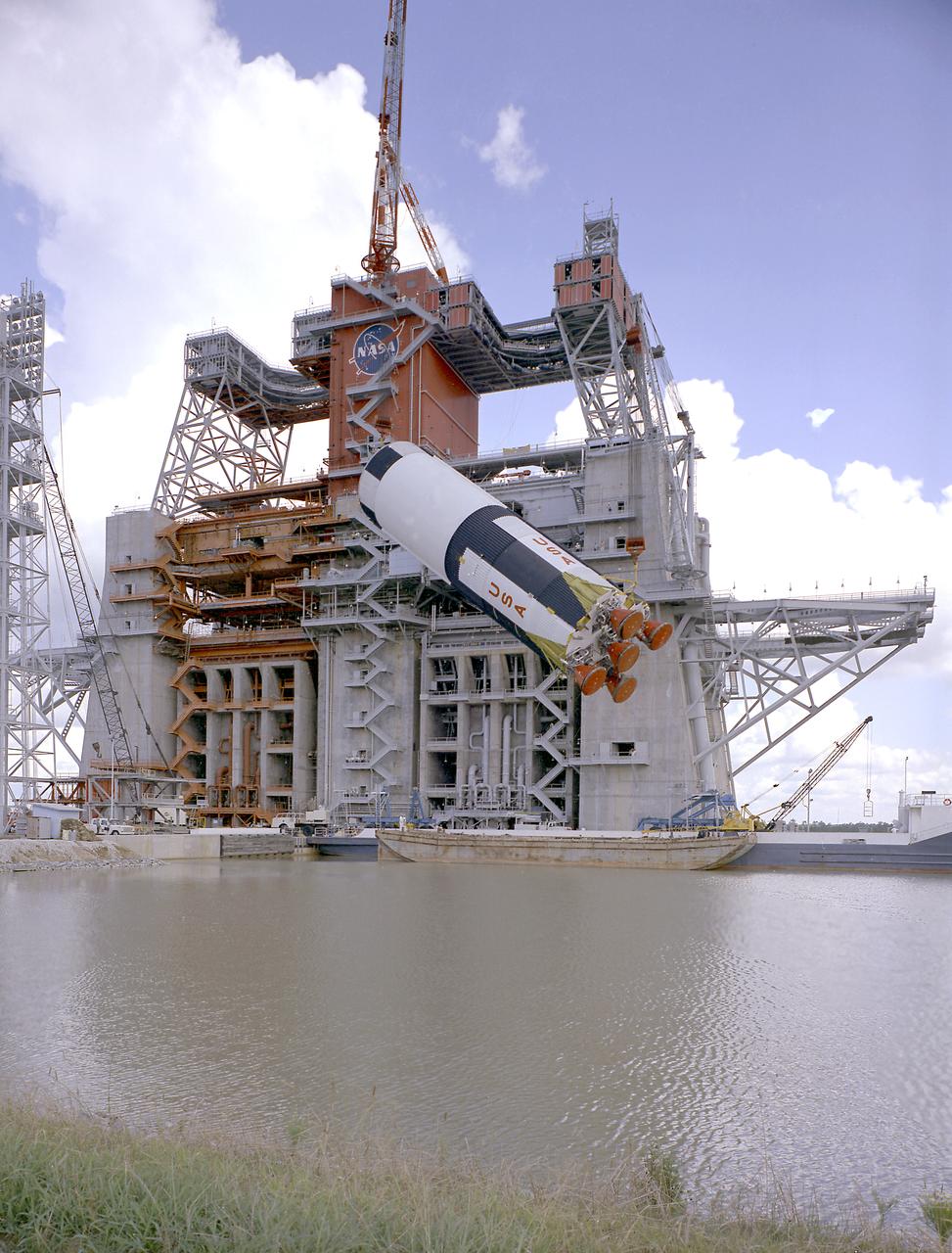
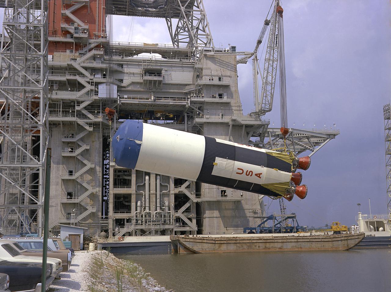
This photograph shows the Saturn V S-II (second) stage being hoisted at the S-II-A2 test stand at the Mississippi Test Facility (MTF). When the Saturn V booster stage (S-IC) burns out and drops away, power for the Saturn will be provided by the 82-foot-long and 33-foot-diameter S-II stage. Developed by the Space Division of North American Aviation under the direction of the Marshall Space Flight Center, the stage utilized five J-2 engines, each producing 200,000 pounds of thrust. The engines used liquid oxygen and liquid hydrogen as propellants. Static test of ground test versions of the S-II stage were conducted at North American Aviation's Santa Susana, California test site. All flight stages were tested at the Mississippi Test Facility, Bay St. Louis, Mississippi. MTF was renamed to the National Space Technology Laboratory (NSTL) in 1974 and later to the Sternis Space Center in May 1988.
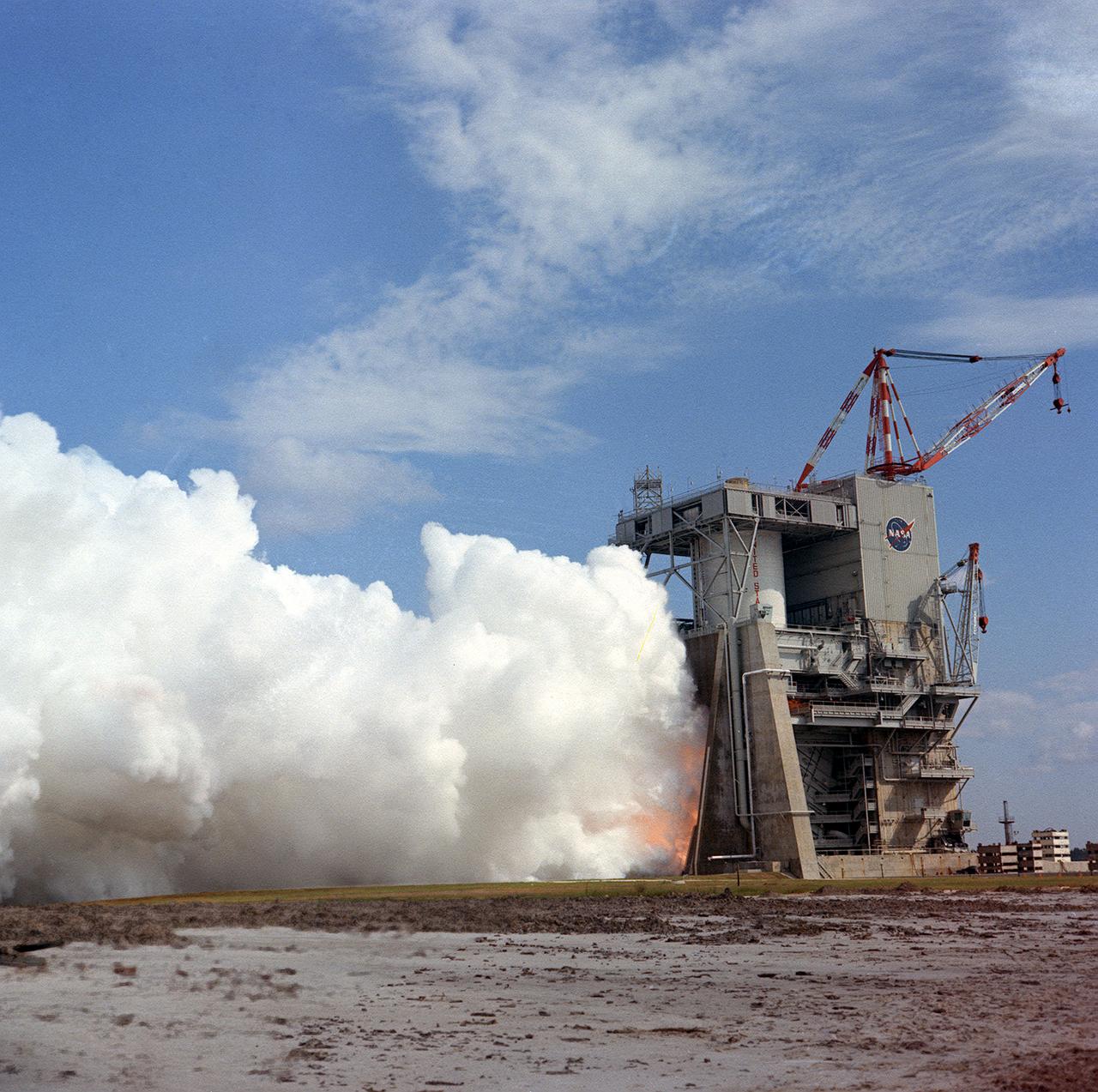
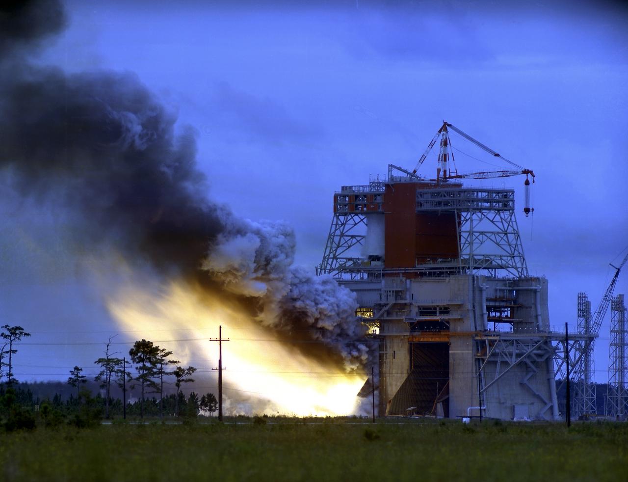
This photograph shows a test firing of the the Saturn V S-II (second) stage at the Mississippi Test Facility's (MTF) S-II test stand. When the Saturn V booster stage (S-IC) burns out and drops away, power for the Saturn will be provided by the 82-foot-long and 33-foot-diameter S-II stage. Developed by the Space Division of North American Aviation under the direction of the Marshall Space Flight Center, the stage utilized five J-2 engines, each producing 200,000 pounds of thrust. The engines used liquid oxygen and liquid hydrogen as propellants. Static test of ground test versions of the S-II stage were conducted at North American Aviation's Santa Susana, California test site. All flight stages were tested at the Mississippi Test Facility, Bay St. Louis, Mississippi. MTF was renamed to the National Space Technology Laboratory (NSTL) in 1974 and later to the Sternis Space Center in May 1988.
This photograph shows a test firing of the the Saturn V S-II (second) stage at the Mississippi Test Facility's (MTF) S-II test stand. When the Saturn V booster stage (S-IC) burns out and drops away, power for the Saturn will be provided by the 82-foot-long and 33-foot-diameter S-II stage. Developed by the Space Division of North American Aviation under the direction of the Marshall Space Flight Center, the stage utilized five J-2 engines, each producing 200,000 pounds of thrust. The engine used liquid oxygen and liquid hydrogen as its propellants. Static test of ground test versions of the S-II stage were conducted at North American Aviation's Santa Susana, California test site. All flight stages were tested at the Mississippi Test Facility, Bay St. Louis, Mississippi. The MTF was renamed to the National Space Technology Laboratory (NSTL) in 1974 and later to the Sternis Space Center (SSC) in May 1988.
This photograph shows the Saturn V S-II (second) stage of the Apollo 6 mission being lowered atop of the S-IC (first) stage during the final assembly operations in the Vehicle Assembly Building (VAB) at the Kennedy Space Center. The Apollo 6 mission was the second Saturn V unmanned flight for testing an emergency detection system. The launch occurred on April 4, 1968.
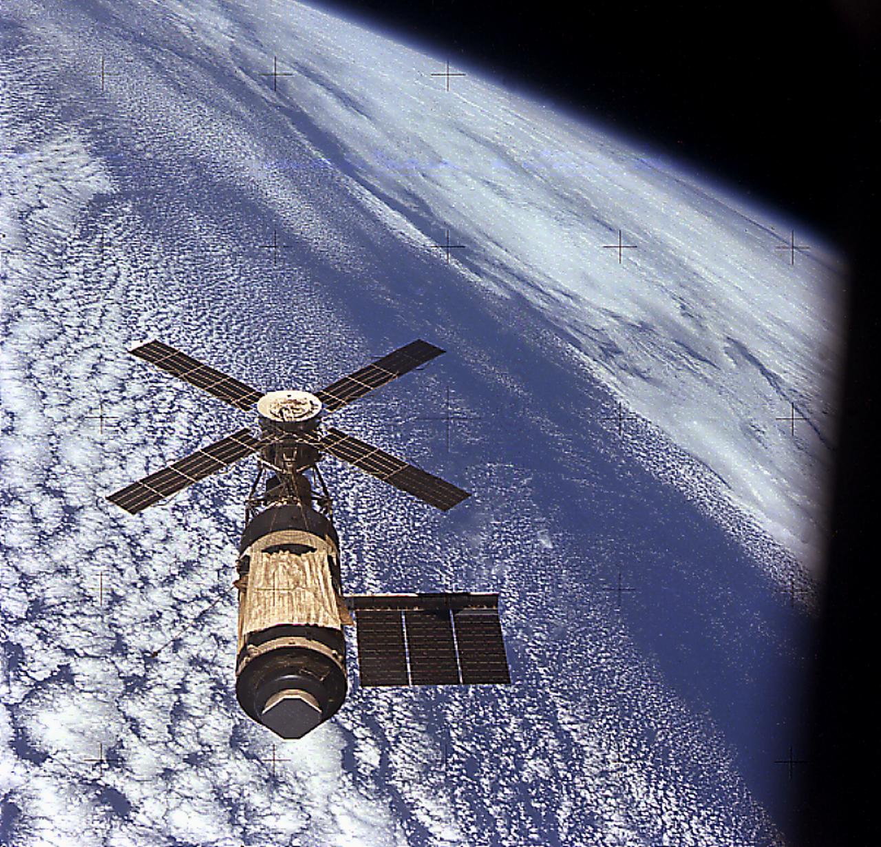
The idea that ultimately became Skylab first surfaced in 1962 as a proposal to convert a spent Saturn upper stage (Saturn V S-II stage) into an orbital workshop. In 1968, the Marshall Space Flight Center proposed an alternative to the wet workshop concept of refurbishing a space station in orbit. Instead, a fully equipped dry workshop could be launched as a complete unit ready for occupancy. Skylab became the free world's first space station. Launched in May 1973, the Skylab space station was occupied in succession by three teams of three crewmembers. These crews spent 28, 59, and 84 days respectively, orbiting the Earth and performing nearly 300 experiments. This view of Skylab in orbit was taken by the Skylab 4 (the last Skylab mission) crew.
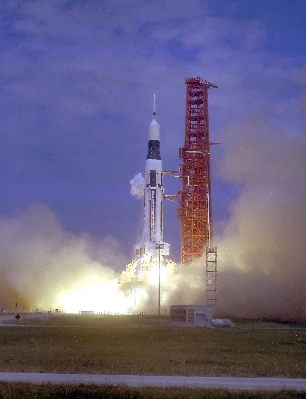
The launch of the SA-7 (Saturn I Block II) was on September 18, 1964. The SA-7 mission was the second orbital flight of the S-IV stage (second stage) with the payload consisting of the Apollo command and service module's instrument unit. The Saturn I Block II vehicle had two live stages, and were basically in the two-stage configuration of the Saturn I vehicle. While the tank arrangement and the engine patterns were the same, there were marked changes between the Block I and II versions. The first stage (S-I stage) was an improved version of the Block I S-I stage. The Block II S-1 stage had eight fins added for greater aerodynamic stability in the lower atmosphere.
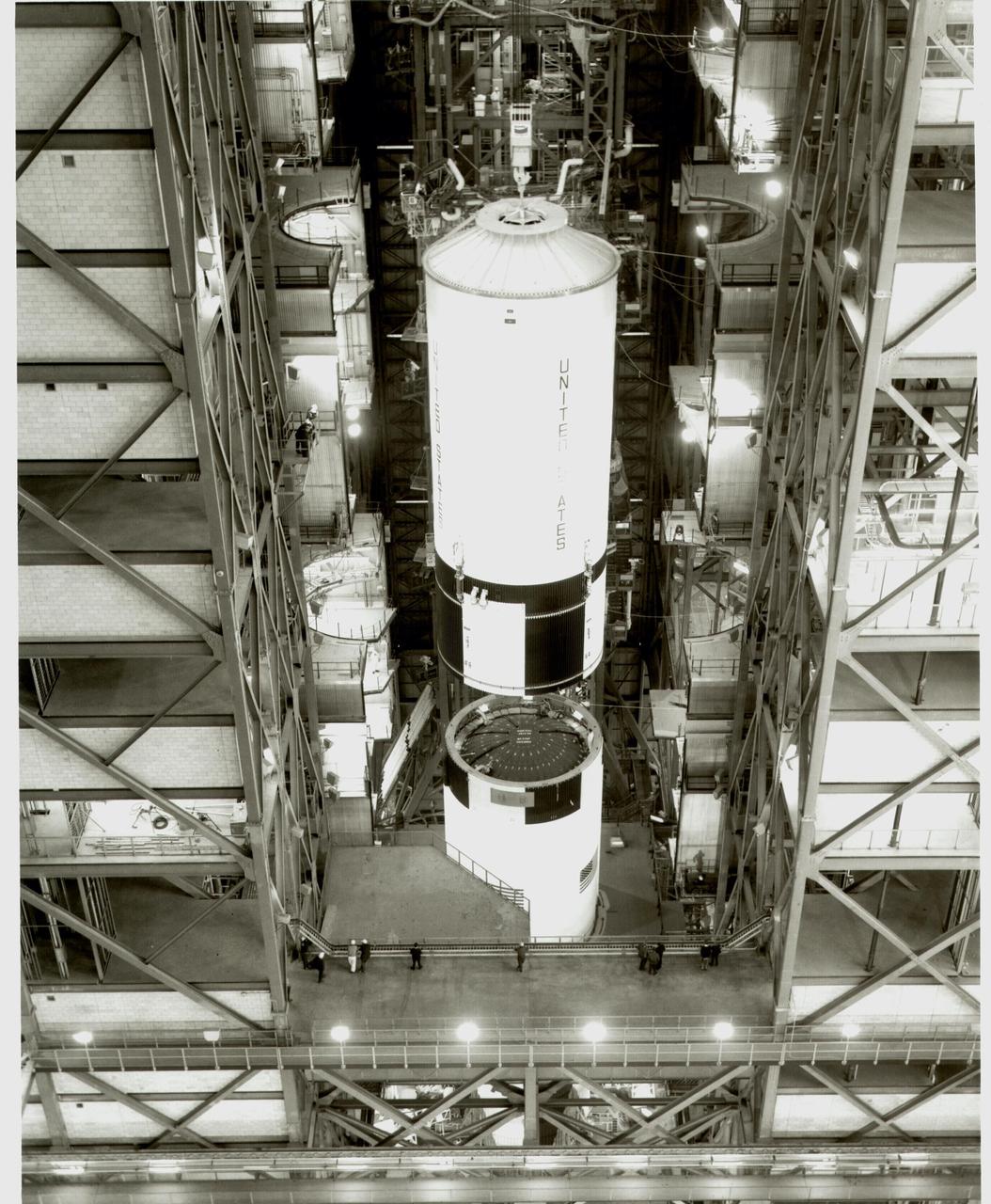
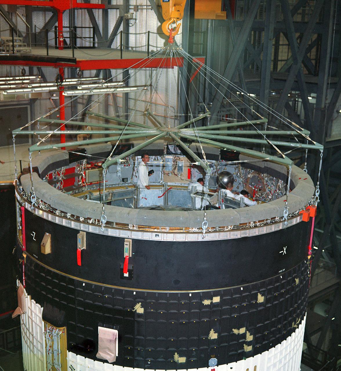
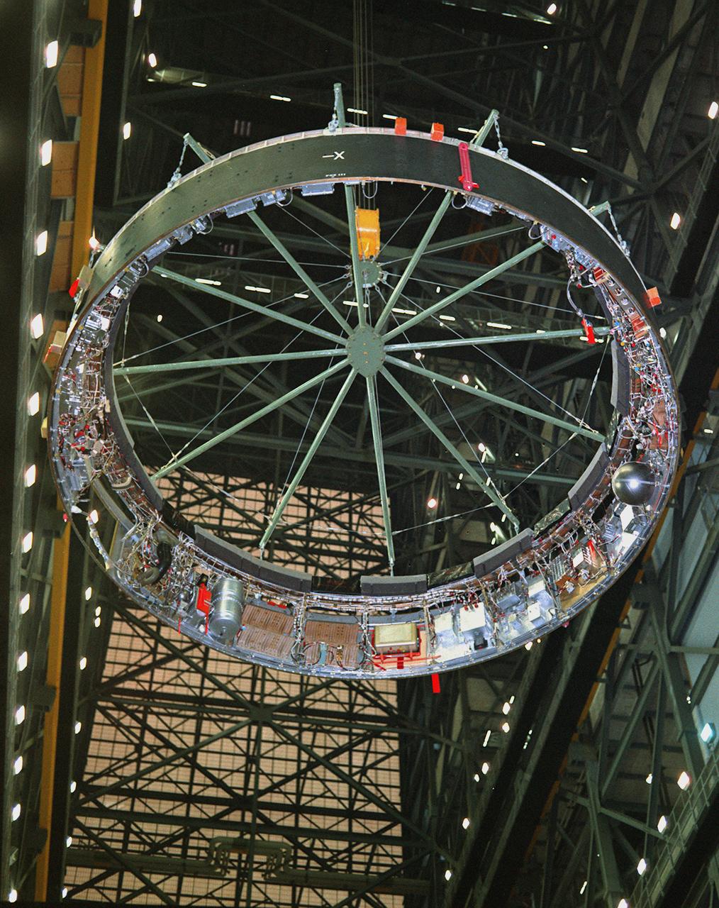
KENNEDY SPACE CENTER, FLA. - Stacking of S-II stage for Saturn 506.
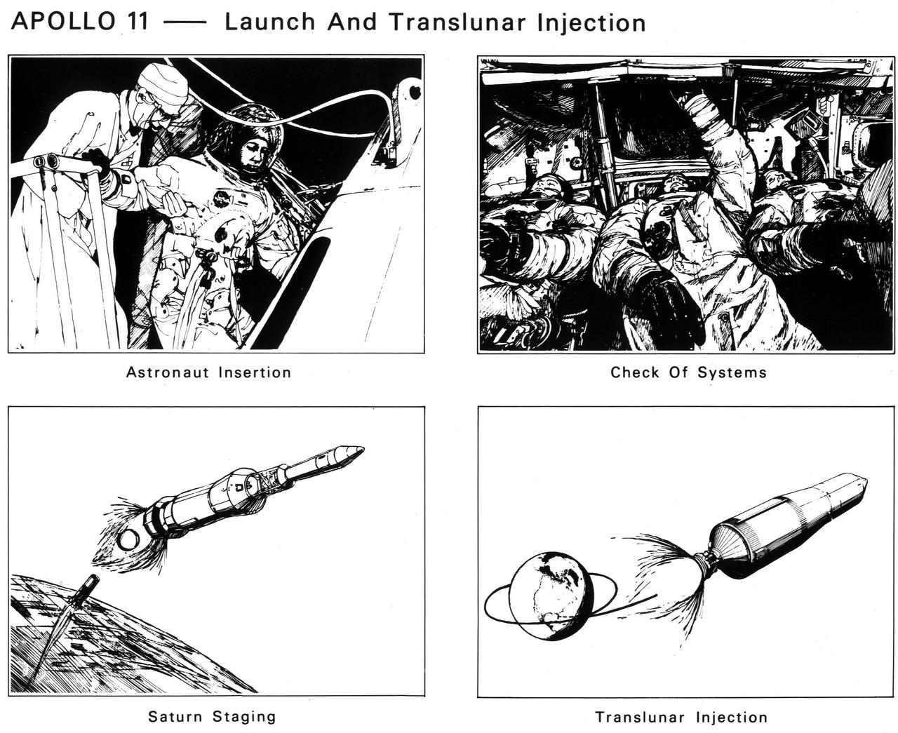
The astronauts enter the spacecraft. After launch and Saturn V first-stage burnout and jettison, the S-II second stage ignites. The crew checks spacecraft systems in Earth orbit before the S-IVB third stage ignites the second time to send Apollo 11 to the Moon
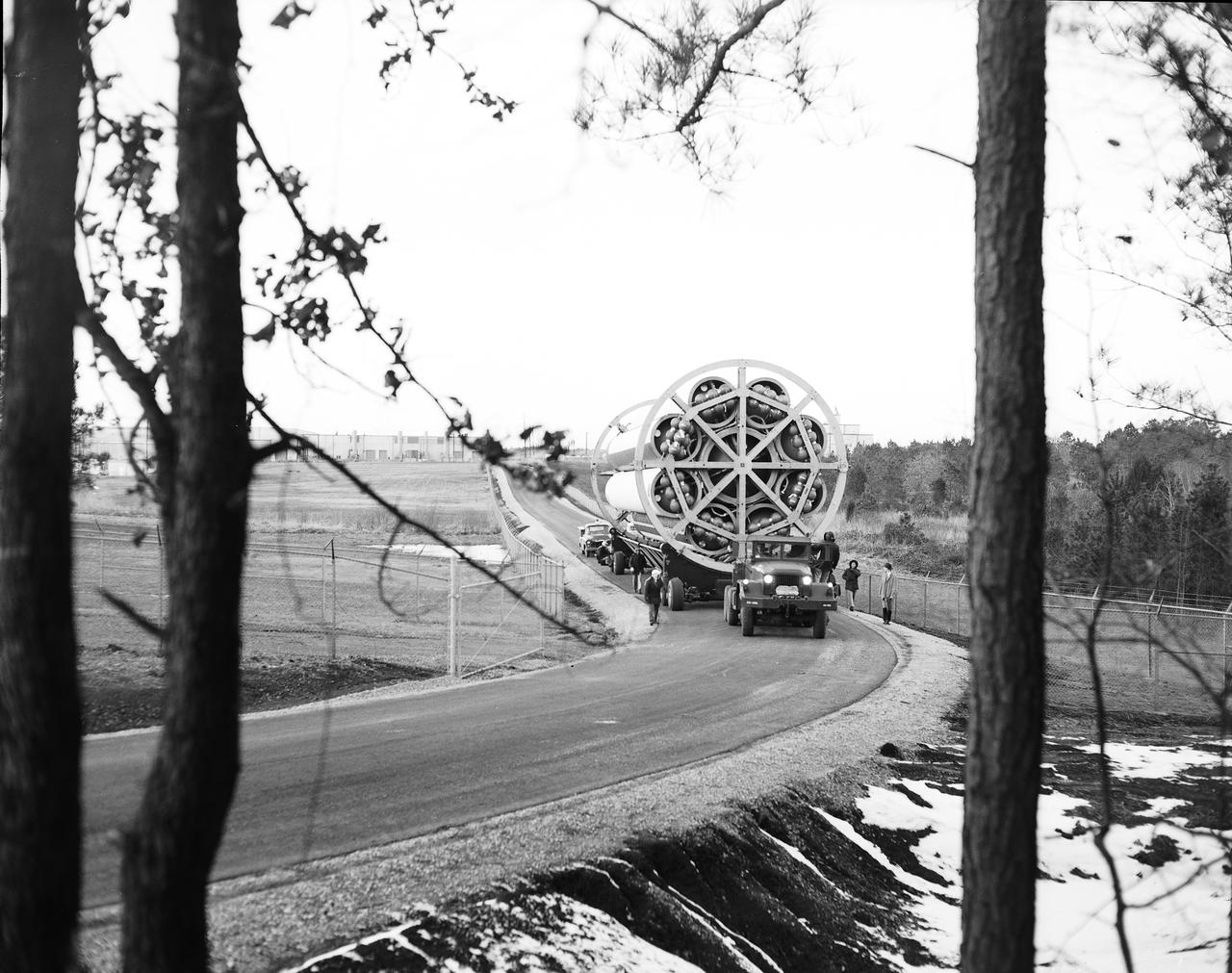
The business end of a Second Stage (S-II) slowly emerges from the shipping container as workers prepare to transport the Saturn V component to the testing facility at MSFC. The Second Stage (S-II) underwent vibration and engine firing tests. The towering 363-foot Saturn V was a multi-stage, multi-engine launch vehicle standing taller than the Statue of Liberty. Altogether, the Saturn V engines produced as much power as 85 Hoover Dams.
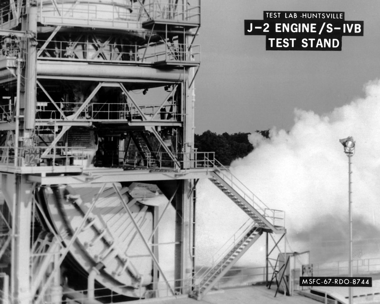
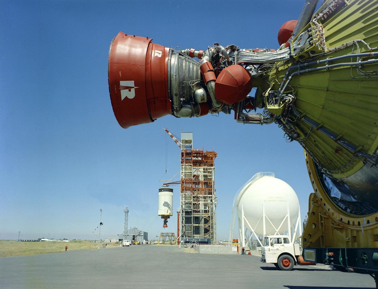
This image depicts the test firing of a J-2 engine in the S-IVB Test Stand at the Marshall Space Flight Center (MSFC). The J-2, developed by Rocketdyne under the direction of MSFC, was propelled by liquid hydrogen and liquid oxygen. A single J-2 was utilized in the S-IVB stage (the second stage for the Saturn IB and third stage for the Saturn V) and in a cluster of five for the second stage (S-II) of the Saturn V. Initially rated at 200,000 pounds of thrust, the engine was later upgraded in the Saturn V program to 230,000 pounds.
This photograph shows a test firing of a Saturn V second stage (S-II) on the S-IC test stand at the Propulsion Test Facility near New Orleans, Louisiana. This second stage component was used in the unmarned test flight of Apollo 4.
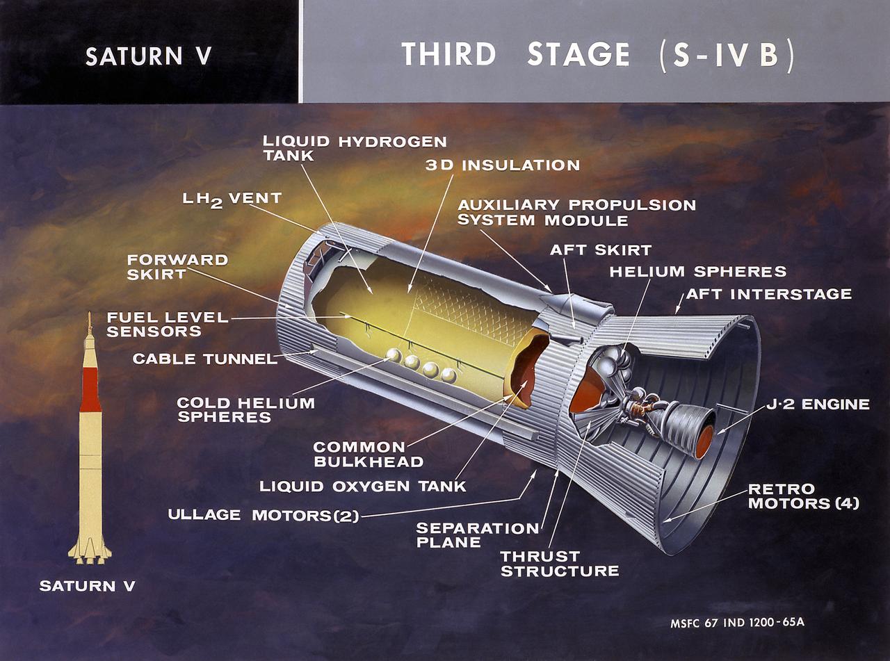
This cutaway illustration shows the Saturn V S-IVB (third) stage with the callouts of its major components. When the S-II (second) stage of the powerful Saturn V rocket burnt out and was separated the remaining units approached orbit around the Earth. Injection into the desired orbit was attaineded as the S-IVB (third stage) was ignited and burnt. The S-IVB stage was powered by a single 200,000-pound thrust J-2 engine and had a re-start capability built in for its J-2 engine. The S-IVB restarted to speed the Apollo spacecraft to escape velocity injecting it and the astronauts into a moon trajectory.
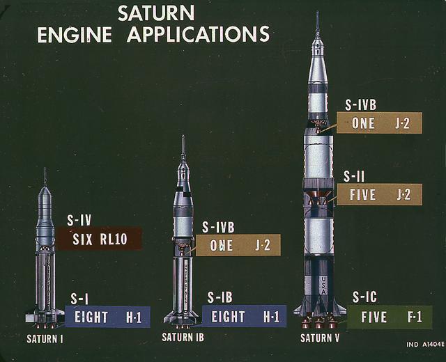
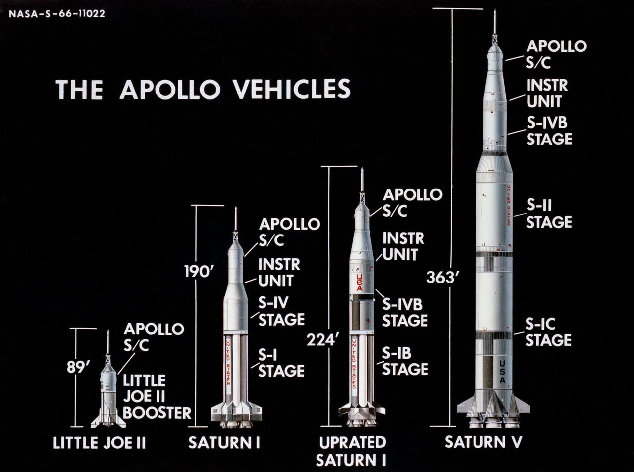
This image illustrates the basic differences between the three Saturn launch vehicles developed by the Marshall Space Flight Center. The Saturn I, consisted of two stages, the S-I (eight H-1 engines) and the S-IV (six RL-10 engines). The Saturn IB (center) also consisted of two stages, the S-IB (eight H-1 engines) and the S-IVB (one J-2 engine). The Saturn V consisted of three stages, the S-IC (five F-1 engines), the S-II (five J-2 engines), and the S-IVB (one J-2 engine).
This image depicts the Saturn V S-IVB (third) stage for the Apollo 10 mission being removed from the Beta Test Stand 1 after its acceptance test at the Douglas Aircraft Company's Sacramento Test Operations (SACTO) facility. After the S-II (second) stage dropped away, the S-IVB (third) stage was ignited and burned for about two minutes to place itself and the Apollo spacecraft into the desired Earth orbit. At the proper time during this Earth parking orbit, the S-IVB stage was re-ignited to speed the Apollo spacecraft to escape velocity injecting it and the astronauts into a moon trajectory. Developed and manufactured by the Douglas Aircraft Company in California, the S-IVB stage measures about 21.5 feet in diameter, about 58 feet in length, and powered by a single 200,000-pound-thrust J-2 engine with a re-start capability. The S-IVB stage was also used on the second stage of the Saturn IB launch vehicle.
After the S-II (second) stage dropped away, the S-IVB (third) stage ignited and burned for about two minutes to place itself and the Apollo spacecraft into the desired Earth orbit. At the proper time during this Earth parking orbit, the S-IVB stage was re-ignited to speed the Apollo spacecraft to escape velocity, injecting it and the astronauts into a moon trajectory. Developed and manufactured by the Douglas Aircraft Company in Huntington, California, the S-IVB stage measures about 21.5 feet in diameter, about 58 feet in length and is powered by a single 200,000-pound-thrust J-2 engine with a re-start capability. The S-IVB stage was also used on the second stage of the Saturn IB launch vehicle. The fully-assembled S-IVB (third) stage for the AS-503 (Apollo 8 mission) launch vehicle is pictured in the Douglas' vertical checkout building.
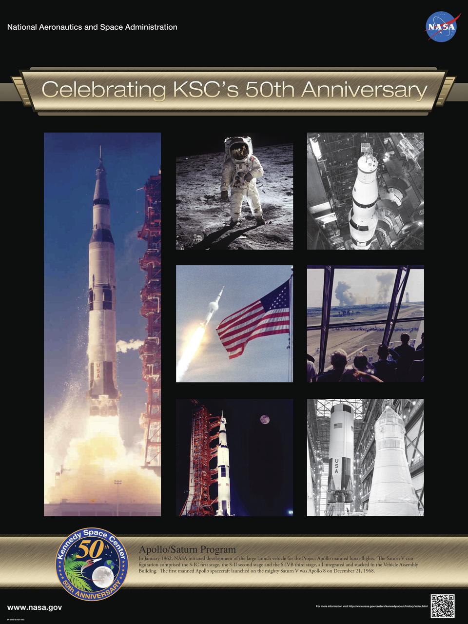
Apollo/Saturn Program: In January 1962, NASA initiated development of the large launch vehicle for the Project Apollo manned lunar flights. The Saturn V configuration comprised the S-IC first stage, the S-II second stage and the S-IVB third stage, all integrated and stacked in the Vehicle Assembly Building. The first manned Apollo spacecraft launched on the mighty Saturn V was Apollo 8 on December 21, 1968. Poster designed by Kennedy Space Center Graphics Department/Greg Lee. Credit: NASA
Developed at MSFC under the direction of Dr. Wernher von Braun, the SA-5 incorporated a Saturn I, Block II engine. Launched on January 29, 1964, SA-5 was the first two stage (Block II) Saturn with orbital capability and performed the first test of Instrument Unit and successful stage separation. Block II vehicles had two live stages, and were basically in the two-stage configuration of the Saturn I vehicle. There were marked changes between the Block I and II versions. The Block II S-I stage had eight fins added for greater aerodynamic stability in the lower atmosphere. All Block II H-1 engines had a thrust of 188,000 pounds each for a combined thrust over 1,500,000 pounds. The Block II second stage (S-IV) had six RL-10 hydrogen-oxygen engines, each producing a thrust of 15,000 pounds for a total combined thrust of 90,000 pounds. A motion picture camera capsule loated on stage I was successful recovered.
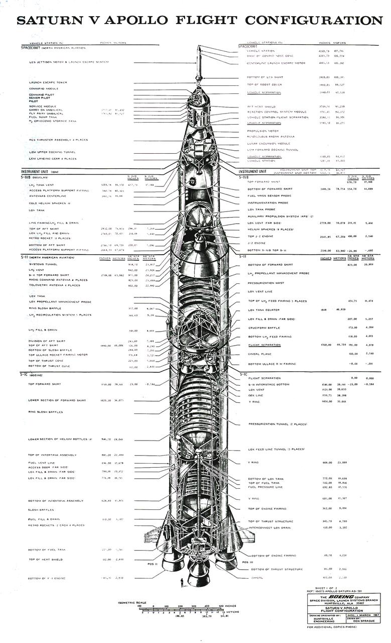
The Saturn V configuration is shown in inches and meters as illustrated by the Boeing Company. The Saturn V vehicle consisted of three stages: the S-IC (first) stage powered by five F-1 engines, the S-II (second) stage powered by five J-2 engines, the S-IVB (third) stage powered by one J-2 engine. A top for the first three stages was designed to contain the instrument unit, the guidance system, the Apollo spacecraft, and the escape system. The Apollo spacecraft consisted of the lunar module, the service module, and the command module. The Saturn V was designed perform lunar and planetary missions and it was capable of placing 280,000 pounds into Earth orbit.
Pictured is a J-2 engine being processed at Marshall Space Flight Center (MSFC). A single J-2 engine was utilized on the S-IVB stage, the second stage of the Saturn IB and the third stage of the Saturn V vehicles, while a cluster of five J-2 engines powered the second (S-II) stage of the Saturn V launch vehicle. The Saturn V was designed, developed, and tested by engineers at MSFC.
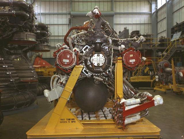
Pictured is a J-2 engine being processed at Marshall Space Flight Center (MSFC). A single J-2 engine was utilized on the S-IVB stage, the second stage of the Saturn IB and the third stage of the Saturn V vehicles, while a cluster of five J-2 engines powered the second (S-II) stage of the Saturn V launch vehicle. The Saturn V was designed, developed, and tested by engineers at MSFC.
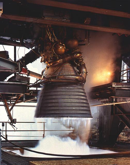
A J-2 engine undergoes static firing. The J-2, developed under the direction of the Marshall Space Flight Center, was propelled by liquid hydrogen and liquid oxygen. A single J-2 was utilized in the S-IVB stage (the second stage for the Saturn IB and third stage for the Saturn V) and in a cluster of five for the second stage (S-II) of the Saturn V. Initially rated at 200,000 pounds of thrust, the engine was later uprated in the Saturn V program to 230,000 pounds.

This Saturn V S-II (second) stage is being lifted into position for a test at the Vehicle Assembly Building at the Kennedy Space Center. When the Saturn V booster stage (S-IC) burned out and dropped away, power for the Saturn was provided by the 82-foot-long and 33-foot-diameter S-II stage. Developed by the Space Division of North American Aviation under the direction of the Marshall Space Flight Center, the stage utilized five J-2 engines, each producing 200,000 pounds of thrust. The engines used liquid oxygen and liquid hydrogen as propellants. The towering 363-foot Saturn V was a multi-stage, multi-engine launch vehicle standing taller than the Statue of Liberty. Altogether, the Saturn V engines produced as much power as 85 Hoover Dams.
This photograph is a view of the Saturn V S-IC (first) test stage being hoisted into the S-IC-B1 test stand at the Mississippi Test Facility (MTF), Bay St. Louis, Mississippi. This stage was used to prove the operational readiness of the stand. Begirning operations in 1966, the MTF has two test stands; a dual-position structure for running the S-IC stage at full throttle, and two separate stands for the S-II (Saturn V third) stage. It became the focus of the static test firing program. The completed S-IC stage was shipped from the Michoud Assembly Facility (MAF) to the MTF. The stage was then installed into the 124-meter-high test stand for static firing tests before shipment to the Kennedy Space Center for final assembly of the Saturn V vehicle. The MTF was renamed to the National Space Technology Laboratory (NSTL) in 1974 and later to the Stennis Space Center (SSC) in May 1988.
This photograph is a view of the Saturn V S-IC-5 (first) flight stage being hoisted into the S-IC-B1 test stand at the Mississippi Test Facility (MTF), Bay St. Louis, Mississippi. Begirning operations in 1966, the MTF has two test stands, a dual-position structure for running the S-IC stage at full throttle, and two separate stands for the S-II (Saturn V third) stage. It became the focus of the static test firing program. The completed S-IC stage was shipped from Michoud Assembly Facility (MAF) to the MTF. The stage was then installed into the 124-meter-high test stand for static firing tests before shipment to the Kennedy Space Center for final assembly of the Saturn V vehicle. The MTF was renamed to the National Space Technology Laboratory (NSTL) in 1974 and later to the Stennis Space Center (SSC) in May 1988.
This photograph is a view of the Saturn V S-IC-5 (first) flight stage static test firing at the S-IC-B1 test stand at the Mississippi Test Facility (MTF), Bay St. Louis, Mississippi. Begirning operations in 1966, the MTF has two test stands, a dual-position structure for running the S-IC stage at full throttle, and two separate stands for the S-II (Saturn V third) stage. It became the focus of the static test firing program. The completed S-IC stage was shipped from Michoud Assembly Facility (MAF) to the MTF. The stage was then installed into the 407-foot-high test stand for the static firing tests before shipment to the Kennedy Space Center for final assembly of the Saturn V vehicle. The MTF was renamed to the National Space Technology Laboratory (NSTL) in 1974 and later to the Stennis Space Center (SSC) in May 1988.
This photograph is a view of the Saturn V S-IC-5 (first) flight stage being hoisted into the S-IC-B1 test stand at the Mississippi Test Facility (MTF), Bay St. Louis, Mississippi. Begirning operations in 1966, the MTF has two test stands, a dual-position structure for running the S-IC stage at full throttle, and two separate stands for the S-II (Saturn V third) stage. It became the focus of the static test firing program. The completed S-IC stage was shipped from Michoud Assembly Facility (MAF) to the MTF. The stage was then installed into the 124-meter-high test stand for static firing tests before shipment to the Kennedy Space Center for final assembly of the Saturn V vehicle. The MTF was renamed to the National Space Technology Laboratory (NSTL) in 1974 and later to the Stennis Space Center (SSC) in May 1988.
This is a view of the Saturn V S-IVB (third) stage for the AS-209 (Apollo-Soyuz test project backup vehicle) on a transporter in the right foreground, and the S-IVB stage for AS-504 (Apollo 9 mission) being installed in the Beta Test Stand 1 at the SACTO facility in California. After the S-II (second) stage dropped away, the S-IVB (third) stage ignited and burned for about two minutes to place itself and the Apollo spacecraft into the desired Earth orbit. At the proper time during this Earth parking orbit, the S-IVB stage was re-ignited to speed the Apollo spacecraft to escape velocity and inject it and the astronauts into a moon trajectory. Developed and manufactured by the Douglas Aircraft Company in California, the S-IVB stage measures about 21.5 feet in diameter, about 58 feet in length, and is powered by a single 200,000-pound-thrust J-2 engine with a re-start capability. The S-IVB stage was also used on the second stage of the Saturn IB launch vehicle.
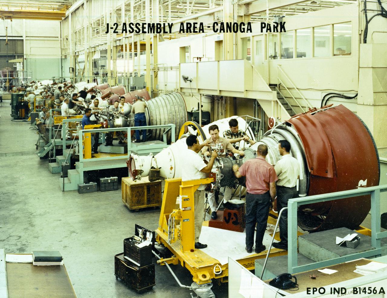
Workmen inspect a J-2 engine at Rocketdyne's Canoga Park, California production facility. The J-2, developed under the direction of the Marshall Space Flight Center, was propelled by liquid hydrogen and liquid oxygen. A single J-2 engine was used in the S-IVB stage (the second stage of the Saturn IB and third stage for the Saturn V) and a cluster of five J-2 engines was used to propel the second stage of the Saturn V, the S-II. Initially rated at 200,000 pounds of thrust, the J-2 engine was later uprated in the Saturn V program to 230,000 pounds.
The launch of the SA-5 on January 29, 1964 was the fifth Saturn I launch vehicle. The SA-5 marked a number of firsts in the Marshall Space Flight Center-managed Saturn development program, including the first flight of Saturn I Block II vehicle with eight aerodynamic fins at the bottom of the S-I stage (first stage) for enhanced stability in flight. This also was the first flight of a live S-IV (second or upper) stage with the cluster of six liquid hydrogen-fueled RL-10 engines. the first successful second stage separation, and the first use of the Launch Complex 37.
This photograph shows the launch of the SA-513, a modified unmarned two-stage Saturn V vehicle for the Skylab-1 mission, which placed the Skylab cluster into the Earth orbit on May 14, 1973. The initial step in the Skylab mission was the launch of a two-stage Saturn V booster, consisting of the S-IC first stage and the S-II second stage, from Launch Complex 39A at the Kennedy Space Center in Florida. Its payload was the unmanned Skylab, which consisted of the Orbital Workshop, the Airlock Module, the Multiple Docking Adapter, the Apollo Telescope Mount and an Instrument Unit.
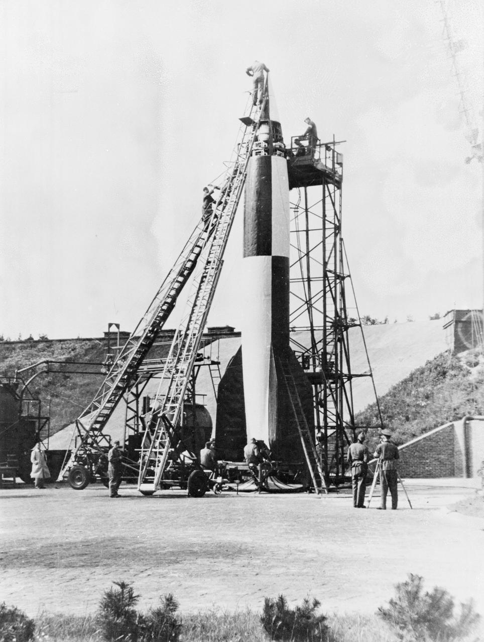
German technicians stack the various stages of the V-2 rocket in this undated photograph. The team of German engineers and scientists who developed the V-2 came to the United States at the end of World War II and worked for the U. S. Army at Fort Bliss, Texas, and Redstone Arsenal in Huntsville, Alabama.
This is a cutaway illustration of the Saturn V launch vehicle with callouts of the major components. The Saturn V is the largest and most powerful launch vehicle developed in the United States. It was a three stage rocket, 363 feet in height, used for sending American astronauts to the moon and for placing the Skylab in Earth orbit. The Saturn V was designed to perform Earth orbital missions through the use of the first two stages, while all three stages were used for lunar expeditions. The S-IC stage (first stage) was powered by five F- engines, which burned kerosene and liquid oxygen to produce more than 7,500,000 pounds of thrust. The S-II (second) stage was powered by five J-2 engines, that burned liquid hydrogen and liquid oxygen and produced 1,150,000 pounds thrust. The S-IVB (third) stage used one J-2 engine, producing 230,000 pounds of thrust, with a re-start capability. The Marshall Space Flight Center and its contractors designed, developed, and assembled the Saturn V launch vehicle stages.
Progress in the Saturn program, depicted below, was described by Dr. Wernher von Braun, Marshall Space Flight Center (MSFC) Director, in an appearance before the Senate Committee of Aeronautical and Space Sciences. "The flight configuration of the giant three-stage Saturn C-1 rocket (later called Saturn I Block I) is seen in the Fabrication and Assembly Engineering Division at MSFC. Dwarfed by the 180-foot C-1 are a Juno II rocket (left rear) and a Mercury-Redstone rocket (front foreground). The C-1 (first version of the Saturn rocket) is composed of an S-1 first stage or booster (rear), powered by eight H-1 engines having a thrust of 1,500,000 pounds, followed by a dummy S-IV second stage and a dummy S-V third stage. The "live" S-IV for later flights, under development by Douglas Aircraft Co., will be powered by four Pratt Whitney LR-119 engines having 17,500,000 pounds thrust each. The live S-V, under development by Convair Division of General Dynamics Corp., will use two LR-119 engines. With all three stages live, the C-1 will be capable of placing 19,000 pounds into a 300-mile Earth orbit, sending 5,000 pounds to escape velocity, or lofting 2,500 pounds to Mars or Venus. The second version Saturn C-2 (later called Saturn 1 Block II) would double these capabilities. Early C-1 flights will employ a live S-1 with dummy upper stages. The first such flight is scheduled late this year."
AS-501, the first flight of the Saturn V launch vehicle, takes flight from Kennedy Space Center's Launch Pad 39A on November 9, 1967. The unmanned mission, also designated Apollo 4, marked the first test flight of the S-IC and S-II stages, developed for the Saturn program under the direction of the Marshall Space Flight Center.
This illustration, with callouts, is of the Saturn V SII (2nd Stage) developed by the Space Division of North American Aviation under the direction of the Marshall Space Flight Center. The 82-foot-long and 33-foot-diameter S-II stage utilized five J-2 engines, each with a 200,000-pound thrust capability. The engine used liquid oxygen and liquid hydrogen as its propellants.
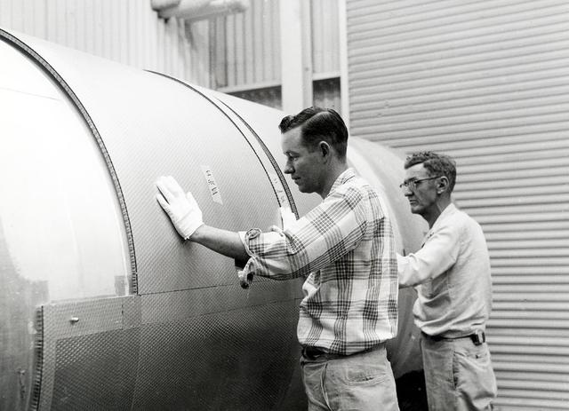
Two technicians apply insulation to the outer surface of the S-II second stage booster for the Saturn V moon rocket. The towering 363-foot Saturn V was a multi-stage, multi-engine launch vehicle standing taller than the Statue of Liberty. Altogether, the Saturn V engines produced as much power as 85 Hoover Dams.
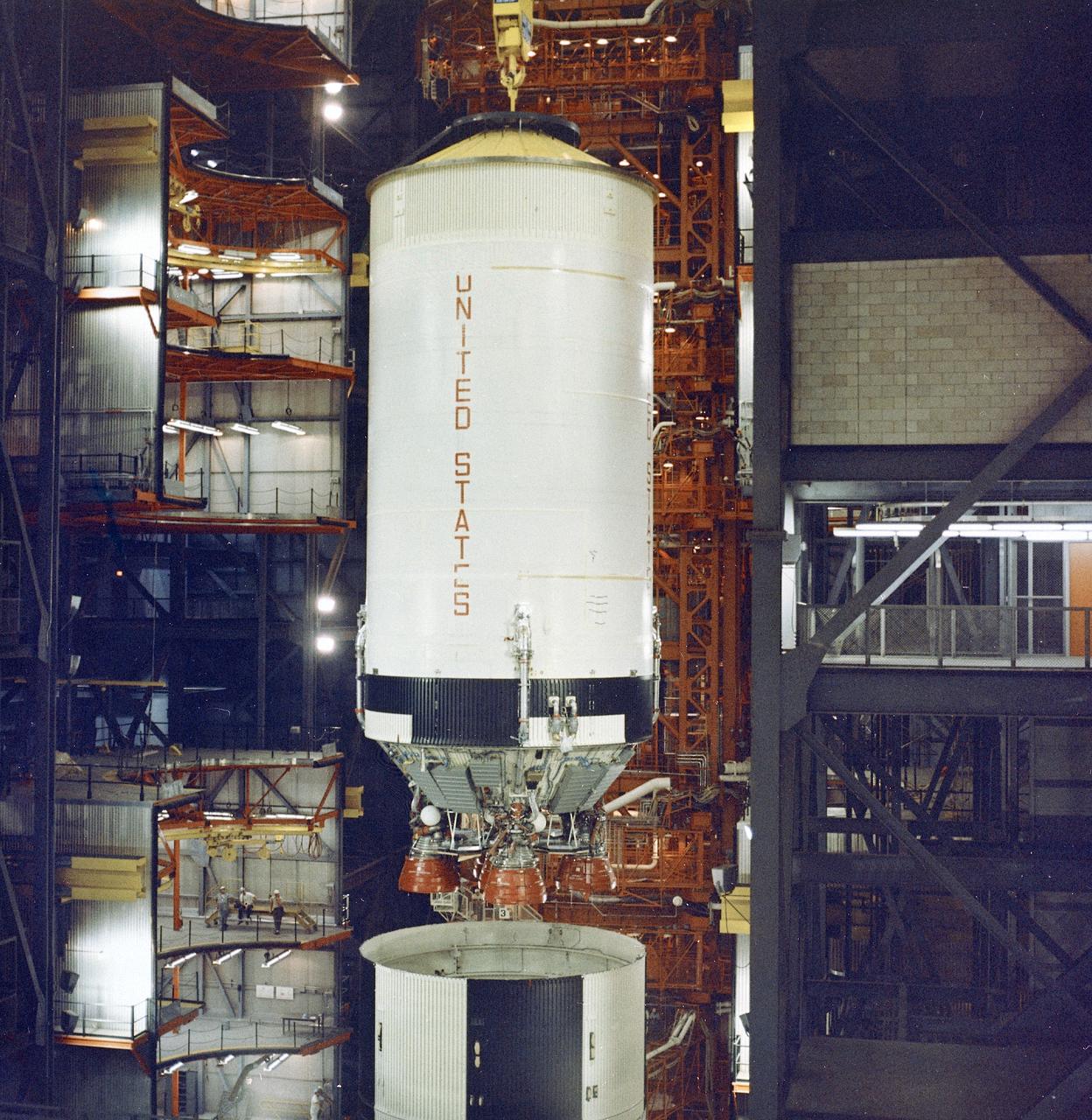
This photograph was taken during the final assembly operation of the Saturn V launch vehicle for the Apollo 4 (SA 501) mission. The instrument unit (IU) was mated atop the S-IC/S-II assembly in the Vehicle Assembly Building high bay at the Kennedy Space Center. The Apollo 4 mission was the first launch of the Saturn V launch vehicle. Objectives of the unmanned Apollo 4 test flight were to obtain flight information on launch vehicle and spacecraft structural integrity and compatibility, flight loads, stage separation, and subsystems operation including testing of restart of the S-IVB stage, and to evaluate the Apollo command module heat shield. The Apollo 4 was launched on November 9, 1967 from KSC.
This photograph was taken during the final assembly operation of the Saturn V launch vehicle for the Apollo 4 (SA 501) mission. The instrument unit (IU) was hoisted to be mated to the S-IC/S-II assembly in the Vehicle Assembly Building high bay at the Kennedy Space Center. The Apollo 4 mission was the first launch of the Saturn V launch vehicle. Objectives of the unmanned Apollo 4 test flight were to obtain flight information on launch vehicle and spacecraft structural integrity and compatibility, flight loads, stage separation, and subsystems operation including testing of restart of the S-IVB stage, and to evaluate the Apollo command module heat shield. The Apollo 4 was launched on November 9, 1967 from KSC.
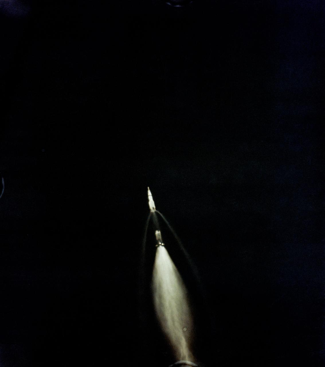
S69-39958 (16 July 1969) --- A 70mm Airborne Lightweight Optical Tracking System (ALOTS) camera, mounted in a pod on a cargo door of a U.S. Air Force EC-135N aircraft, photographed this event in the early moments of the Apollo 11 launch. The mated Apollo spacecraft and Saturn V second (S-II) and third (S-IVB) stages pull away from the expended first (S-1C) stage. Separation occurred at an altitude of about 38 miles, some 55 miles downrange from Cape Kennedy. The aircraft's pod is 20 feet long and 5 feet in diameter. The crew of the Apollo 11 lunar landing mission are astronauts Neil A. Armstrong, Michael Collins, and Edwin E. Aldrin Jr.
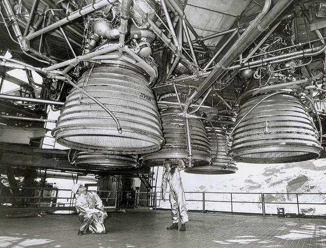
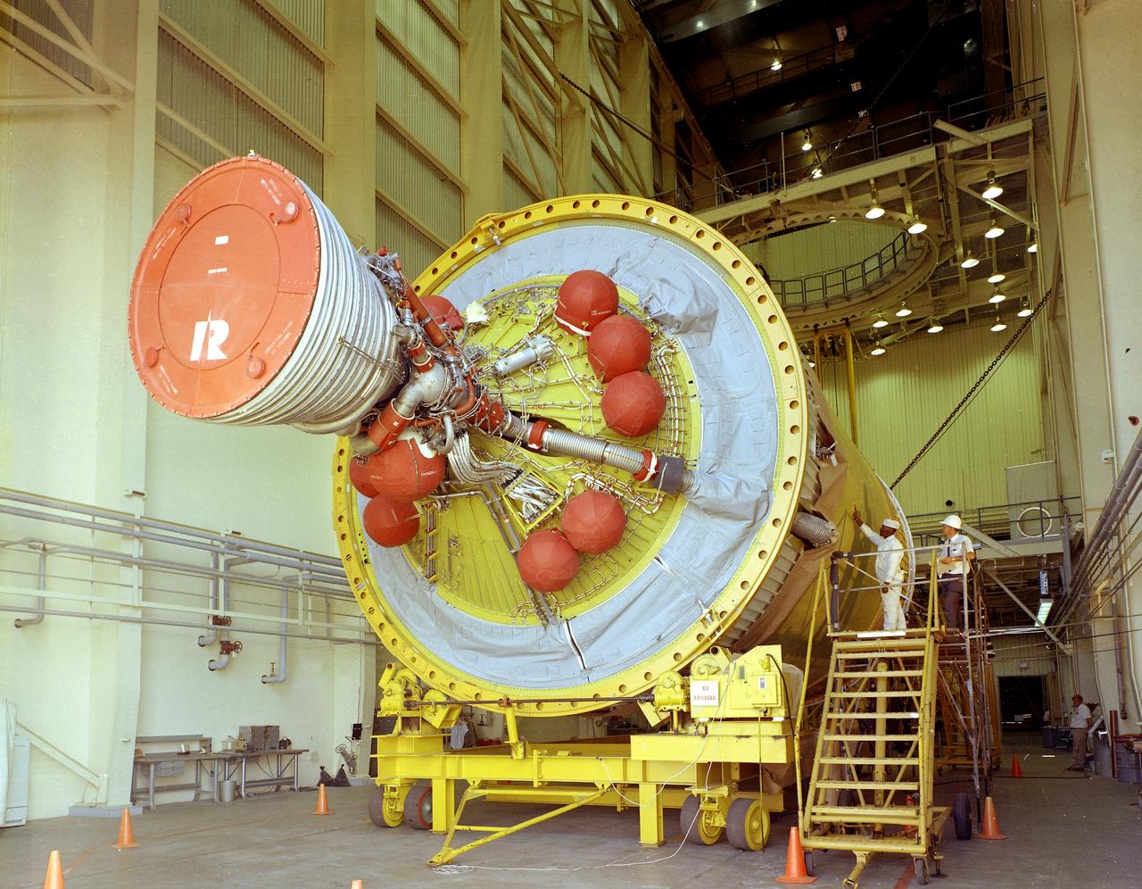
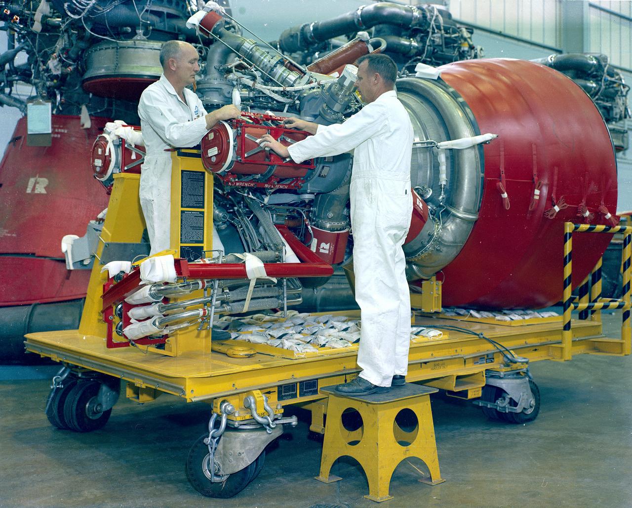
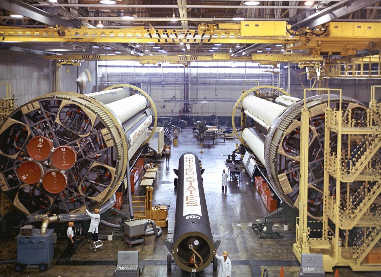
Two workers are dwarfed by the five J-2 engines of the Saturn V second stage (S-II) as they make final inspections prior to a static test firing by North American Space Division. These five hydrogen -fueled engines produced one million pounds of thrust, and placed the Apollo spacecraft into earth orbit before departing for the moon. The towering 363-foot Saturn V was a multi-stage, multi-engine launch vehicle standing taller than the Statue of Liberty. Altogether, the Saturn V engines produced as much power as 85 Hoover Dams.
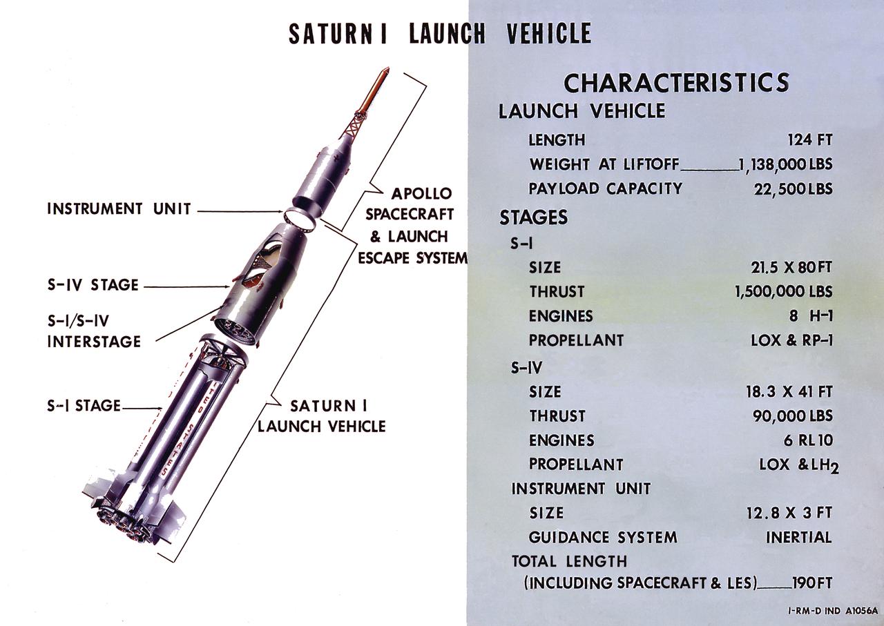
A cutaway illustration of Saturn I launch vehicle characteristics: The Saturn I, first of the Saturn launch vehicles' family, is a two-stage vehicle with a low-earth-orbit payload capability of approximately 25,000 pounds. The research and development program was plarned in two phases or blocks; one for first stage development (Block I) and the second for first and second stage development (Block II). The S-I (first) stage consisted of a cluster of nine propellant tanks and eight H-1 engines built by Rocketdyne, yeilding a total thrust of 1,500,000 pounds. The second stage identified as S-IV, was designed as a single cylinder with a common bulkhead separating the liquid oxygen from the liquid hydrogen. Propulsion was provided by six RL-10 engines built by Pratt Whitney, capable of producing a combined thrust of 90,000 pounds. Of the 10 Saturn I's planned, the first eight were designed and built at the Marshall Space Flight Center. The remaining two were built by the Chrysler Corporation.
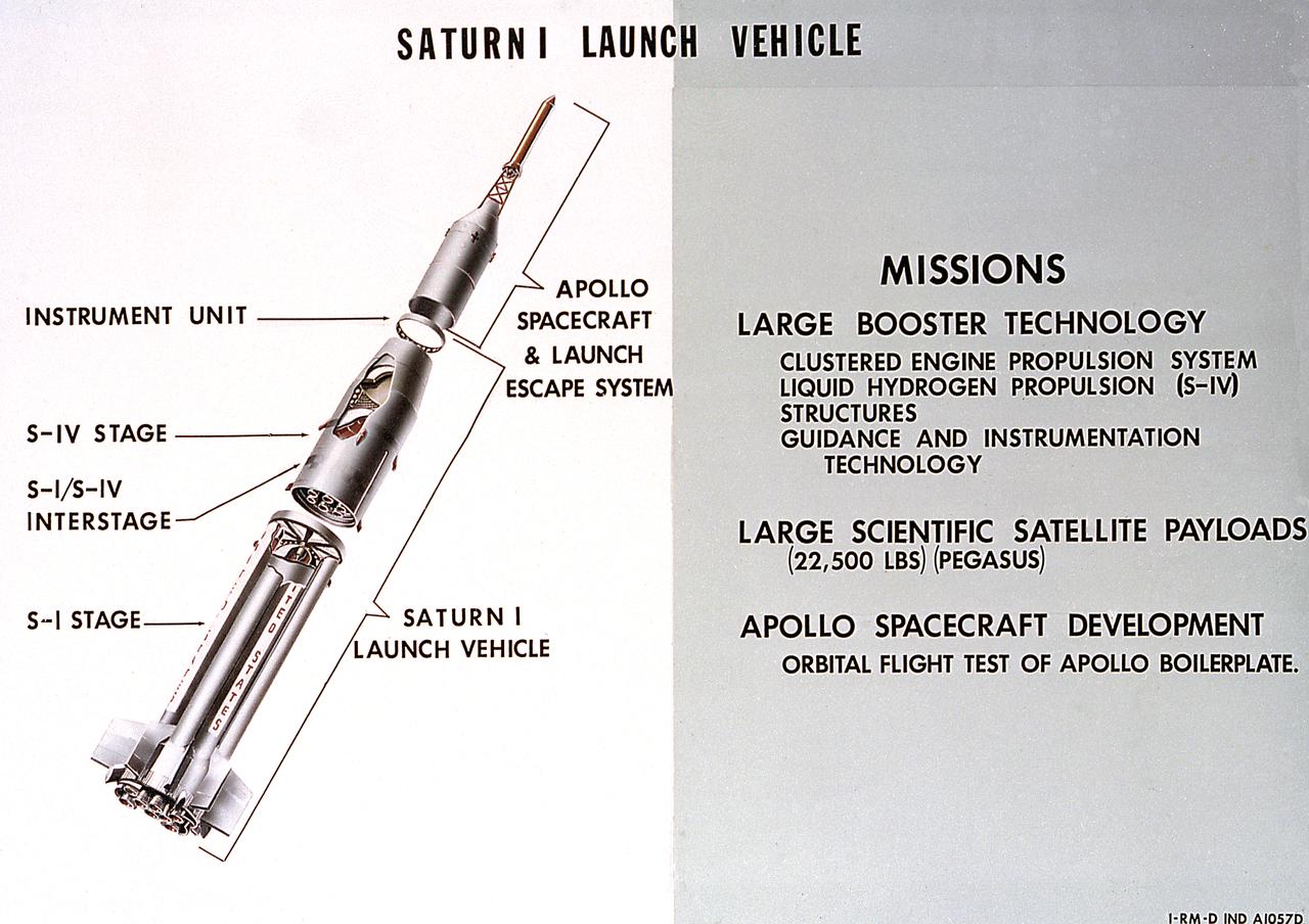
A cutaway illustration of Saturn 1 launch vehicle mission. The Saturn I, first of the Saturn launch vehicles' family, is a two-stage vehicle with a low-earth-orbit payload capability of approximately 25,000 pounds. The research and development program was plarned in two phases or blocks; one for first stage development (Block I) and the second for first and second stage development (Block II). The S-I (first) stage consisted of a cluster of nine propellant tanks and eight H-1 engines built by Rocketdyne, yeilding a total thrust of 1,500,000 pounds. The second stage of Saturn I, identified as S-IV, was designed as a single cylinder with a common bulkhead separating the liquid oxygen from the liquid hydrogen. Propulsion was provided by six RL-10 engines built by Pratt Whitney, capable of producing a combined thrust of 90,000 pounds. Of the 10 Saturn I's planned, the first eight were designed and built at the Marshall Space Flight Center. The remaining two were built by the Chrysler Corporation.
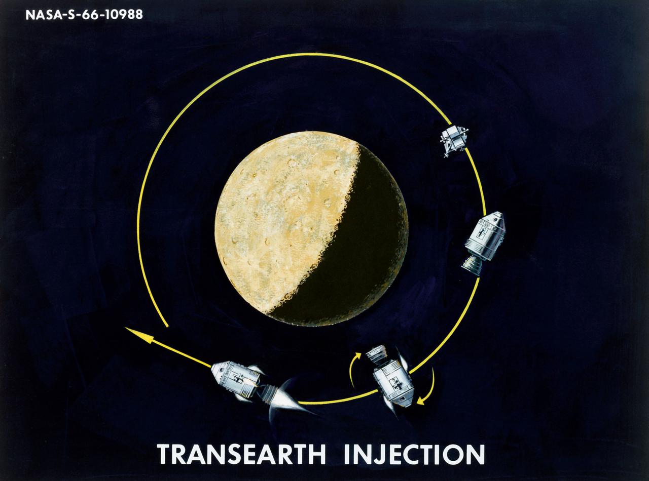
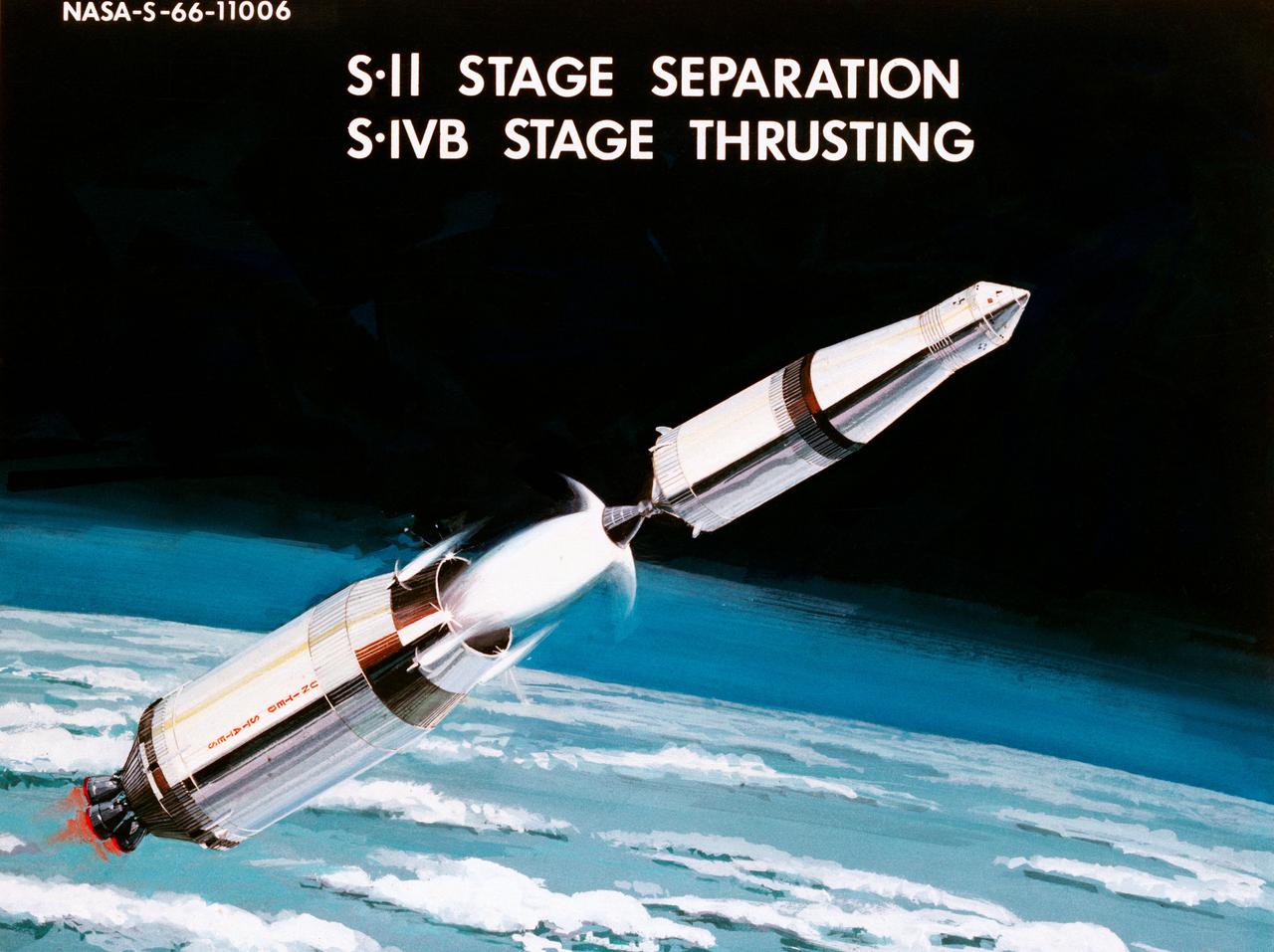
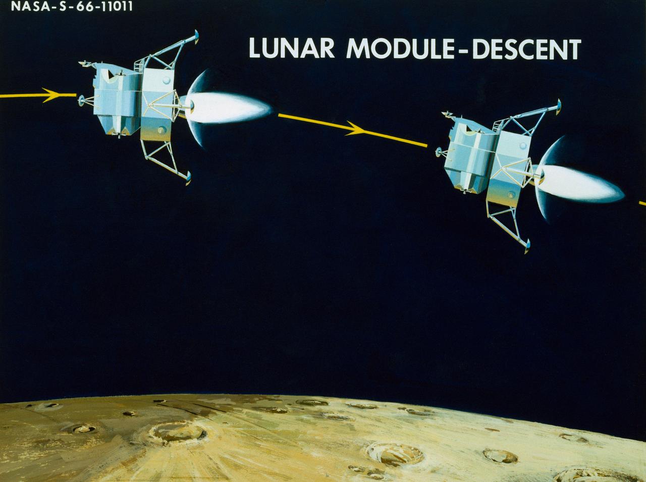
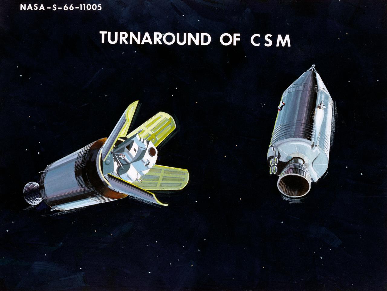
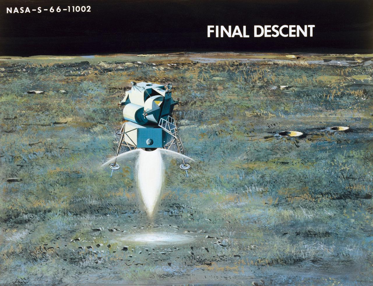
Artist Concepts, Apollo Mission: S66-10983: Ascent Stage Liftoff (S66-05094) S66-10984: Orientation During Ascent Phase (S66-05098) S66-10985: Midcourse Coast (S66-05113) S66-10986: Survey of Landing Site (S66-05117) S66-10987: Lunar Module (LM) Jettison (S66-05089) S66-10988: Trans-Earth Injection (S66-05090) S66-10989: Exploration on Lunar Surface Apollo Surface Lunar Exploration Experiment (ASLEP) S66-10990: Liftoff (S66-05125) S66-10991: Command Module (CM)-Service Module (SM) Separation (S66-05101 N/F) S66-10992: Touchdown on Lunar Surface (S66-05115) S66-10993: Transfer Orbit Insertion (S66-05111) S66-10994: Drogue Parachute Deployment S66-10995: S-IC Stage Separation S-II Stage Thrusting (S66-05099) S66-10996: Jettison Launch Escape System (S66-05114) S66-10997: Main Parachute Deployment (S66-05091) S66-10998: Mid-course correction (S66-05088) S66-10999: Lunar Orbit Insertion (S66-05086) S66-11000: Command Service Module (CSM)-LM Docked in LM Adapter-S-IVB (S66-06526) S66-11001: Docking and Separation of spacecraft from S-IVB (S66-05107) S66-11002: Final Descent (S66-05096) S66-11003: Entry into Earth Atmosphere (S66-05096) S66-11004: Deploy S/C LM Adapter-Separate CSM from LM-S-IVB (S66-06525 & 05105) S66-11005: Turnaround of CSM (S66-05104) S66-11006: S-II Stage Separation S-IVB Stage Thrusting (S66-05102) S66-11007: LM Ascent CSM Docked (S66-05100) S66-11008: Midcourse Correction SPS Mode (S66-05106) S66-11009: Earth Orbit Insertion of S-IVB & S/C (S66-05092) S66-11010: Trans-lunar Injection (S66-05116) S66-11011: LM Descent (S66-05110) S66-11012: S-IVB Stage Operations (S66-05112 N/F) S66-11013: Spacecraft Recovery (S66-05126) S66-11014: Lunar Orbit (S66-05103) S66-11015: CSM-LM Docking (S66-05095) S66-11016: Entry CM (S66-5109) S66-11017: Midcourse Corrections to Lunar Landing (S66-08486) S66-11018: Midcourse Corrections to Lunar Landing w/Overlay (S66-05083) S66-11019: Earth Launch Phase w/Overlay (S66-08485 & 05119) S66-11020: Earth Launch Phase (S66-08487 & S66-05084) S66-11022: Apollo Vehicles (S66-05127) S66-11024: Transfer to LM (S66-05082) S66-11025: Lunar Launch Phase S66-11027: Trans-earth Separation of C/M from S/M-C/M return to Earth (S66-05097) S66-11028: CSM-LM Separation, LM Descent to Moon (S66-05108) MSC, Houston, TX Also available in B&W 12/1965 - 06/1966

Artist Concepts, Apollo Mission: S66-10983: Ascent Stage Liftoff (S66-05094) S66-10984: Orientation During Ascent Phase (S66-05098) S66-10985: Midcourse Coast (S66-05113) S66-10986: Survey of Landing Site (S66-05117) S66-10987: Lunar Module (LM) Jettison (S66-05089) S66-10988: Trans-Earth Injection (S66-05090) S66-10989: Exploration on Lunar Surface Apollo Surface Lunar Exploration Experiment (ASLEP) S66-10990: Liftoff (S66-05125) S66-10991: Command Module (CM)-Service Module (SM) Separation (S66-05101 N/F) S66-10992: Touchdown on Lunar Surface (S66-05115) S66-10993: Transfer Orbit Insertion (S66-05111) S66-10994: Drogue Parachute Deployment S66-10995: S-IC Stage Separation S-II Stage Thrusting (S66-05099) S66-10996: Jettison Launch Escape System (S66-05114) S66-10997: Main Parachute Deployment (S66-05091) S66-10998: Mid-course correction (S66-05088) S66-10999: Lunar Orbit Insertion (S66-05086) S66-11000: Command Service Module (CSM)-LM Docked in LM Adapter-S-IVB (S66-06526) S66-11001: Docking and Separation of spacecraft from S-IVB (S66-05107) S66-11002: Final Descent (S66-05096) S66-11003: Entry into Earth Atmosphere (S66-05096) S66-11004: Deploy S/C LM Adapter-Separate CSM from LM-S-IVB (S66-06525 & 05105) S66-11005: Turnaround of CSM (S66-05104) S66-11006: S-II Stage Separation S-IVB Stage Thrusting (S66-05102) S66-11007: LM Ascent CSM Docked (S66-05100) S66-11008: Midcourse Correction SPS Mode (S66-05106) S66-11009: Earth Orbit Insertion of S-IVB & S/C (S66-05092) S66-11010: Trans-lunar Injection (S66-05116) S66-11011: LM Descent (S66-05110) S66-11012: S-IVB Stage Operations (S66-05112 N/F) S66-11013: Spacecraft Recovery (S66-05126) S66-11014: Lunar Orbit (S66-05103) S66-11015: CSM-LM Docking (S66-05095) S66-11016: Entry CM (S66-5109) S66-11017: Midcourse Corrections to Lunar Landing (S66-08486) S66-11018: Midcourse Corrections to Lunar Landing w/Overlay (S66-05083) S66-11019: Earth Launch Phase w/Overlay (S66-08485 & 05119) S66-11020: Earth Launch Phase (S66-08487 & S66-05084) S66-11022: Apollo Vehicles (S66-05127) S66-11024: Transfer to LM (S66-05082) S66-11025: Lunar Launch Phase S66-11027: Trans-earth Separation of C/M from S/M-C/M return to Earth (S66-05097) S66-11028: CSM-LM Separation, LM Descent to Moon (S66-05108) MSC, Houston, TX Also available in B&W 12/1965 - 06/1966
Artist Concepts, Apollo Mission: S66-10983: Ascent Stage Liftoff (S66-05094) S66-10984: Orientation During Ascent Phase (S66-05098) S66-10985: Midcourse Coast (S66-05113) S66-10986: Survey of Landing Site (S66-05117) S66-10987: Lunar Module (LM) Jettison (S66-05089) S66-10988: Trans-Earth Injection (S66-05090) S66-10989: Exploration on Lunar Surface Apollo Surface Lunar Exploration Experiment (ASLEP) S66-10990: Liftoff (S66-05125) S66-10991: Command Module (CM)-Service Module (SM) Separation (S66-05101 N/F) S66-10992: Touchdown on Lunar Surface (S66-05115) S66-10993: Transfer Orbit Insertion (S66-05111) S66-10994: Drogue Parachute Deployment S66-10995: S-IC Stage Separation S-II Stage Thrusting (S66-05099) S66-10996: Jettison Launch Escape System (S66-05114) S66-10997: Main Parachute Deployment (S66-05091) S66-10998: Mid-course correction (S66-05088) S66-10999: Lunar Orbit Insertion (S66-05086) S66-11000: Command Service Module (CSM)-LM Docked in LM Adapter-S-IVB (S66-06526) S66-11001: Docking and Separation of spacecraft from S-IVB (S66-05107) S66-11002: Final Descent (S66-05096) S66-11003: Entry into Earth Atmosphere (S66-05096) S66-11004: Deploy S/C LM Adapter-Separate CSM from LM-S-IVB (S66-06525 & 05105) S66-11005: Turnaround of CSM (S66-05104) S66-11006: S-II Stage Separation S-IVB Stage Thrusting (S66-05102) S66-11007: LM Ascent CSM Docked (S66-05100) S66-11008: Midcourse Correction SPS Mode (S66-05106) S66-11009: Earth Orbit Insertion of S-IVB & S/C (S66-05092) S66-11010: Trans-lunar Injection (S66-05116) S66-11011: LM Descent (S66-05110) S66-11012: S-IVB Stage Operations (S66-05112 N/F) S66-11013: Spacecraft Recovery (S66-05126) S66-11014: Lunar Orbit (S66-05103) S66-11015: CSM-LM Docking (S66-05095) S66-11016: Entry CM (S66-5109) S66-11017: Midcourse Corrections to Lunar Landing (S66-08486) S66-11018: Midcourse Corrections to Lunar Landing w/Overlay (S66-05083) S66-11019: Earth Launch Phase w/Overlay (S66-08485 & 05119) S66-11020: Earth Launch Phase (S66-08487 & S66-05084) S66-11022: Apollo Vehicles (S66-05127) S66-11024: Transfer to LM (S66-05082) S66-11025: Lunar Launch Phase S66-11027: Trans-earth Separation of C/M from S/M-C/M return to Earth (S66-05097) S66-11028: CSM-LM Separation, LM Descent to Moon (S66-05108) MSC, Houston, TX Also available in B&W 12/1965 - 06/1966

Artist Concepts, Apollo Mission: S66-10983: Ascent Stage Liftoff (S66-05094) S66-10984: Orientation During Ascent Phase (S66-05098) S66-10985: Midcourse Coast (S66-05113) S66-10986: Survey of Landing Site (S66-05117) S66-10987: Lunar Module (LM) Jettison (S66-05089) S66-10988: Trans-Earth Injection (S66-05090) S66-10989: Exploration on Lunar Surface Apollo Surface Lunar Exploration Experiment (ASLEP) S66-10990: Liftoff (S66-05125) S66-10991: Command Module (CM)-Service Module (SM) Separation (S66-05101 N/F) S66-10992: Touchdown on Lunar Surface (S66-05115) S66-10993: Transfer Orbit Insertion (S66-05111) S66-10994: Drogue Parachute Deployment S66-10995: S-IC Stage Separation S-II Stage Thrusting (S66-05099) S66-10996: Jettison Launch Escape System (S66-05114) S66-10997: Main Parachute Deployment (S66-05091) S66-10998: Mid-course correction (S66-05088) S66-10999: Lunar Orbit Insertion (S66-05086) S66-11000: Command Service Module (CSM)-LM Docked in LM Adapter-S-IVB (S66-06526) S66-11001: Docking and Separation of spacecraft from S-IVB (S66-05107) S66-11002: Final Descent (S66-05096) S66-11003: Entry into Earth Atmosphere (S66-05096) S66-11004: Deploy S/C LM Adapter-Separate CSM from LM-S-IVB (S66-06525 & 05105) S66-11005: Turnaround of CSM (S66-05104) S66-11006: S-II Stage Separation S-IVB Stage Thrusting (S66-05102) S66-11007: LM Ascent CSM Docked (S66-05100) S66-11008: Midcourse Correction SPS Mode (S66-05106) S66-11009: Earth Orbit Insertion of S-IVB & S/C (S66-05092) S66-11010: Trans-lunar Injection (S66-05116) S66-11011: LM Descent (S66-05110) S66-11012: S-IVB Stage Operations (S66-05112 N/F) S66-11013: Spacecraft Recovery (S66-05126) S66-11014: Lunar Orbit (S66-05103) S66-11015: CSM-LM Docking (S66-05095) S66-11016: Entry CM (S66-5109) S66-11017: Midcourse Corrections to Lunar Landing (S66-08486) S66-11018: Midcourse Corrections to Lunar Landing w/Overlay (S66-05083) S66-11019: Earth Launch Phase w/Overlay (S66-08485 & 05119) S66-11020: Earth Launch Phase (S66-08487 & S66-05084) S66-11022: Apollo Vehicles (S66-05127) S66-11024: Transfer to LM (S66-05082) S66-11025: Lunar Launch Phase S66-11027: Trans-earth Separation of C/M from S/M-C/M return to Earth (S66-05097) S66-11028: CSM-LM Separation, LM Descent to Moon (S66-05108) MSC, Houston, TX Also available in B&W 12/1965 - 06/1966
Artist Concepts, Apollo Mission: S66-10983: Ascent Stage Liftoff (S66-05094) S66-10984: Orientation During Ascent Phase (S66-05098) S66-10985: Midcourse Coast (S66-05113) S66-10986: Survey of Landing Site (S66-05117) S66-10987: Lunar Module (LM) Jettison (S66-05089) S66-10988: Trans-Earth Injection (S66-05090) S66-10989: Exploration on Lunar Surface Apollo Surface Lunar Exploration Experiment (ASLEP) S66-10990: Liftoff (S66-05125) S66-10991: Command Module (CM)-Service Module (SM) Separation (S66-05101 N/F) S66-10992: Touchdown on Lunar Surface (S66-05115) S66-10993: Transfer Orbit Insertion (S66-05111) S66-10994: Drogue Parachute Deployment S66-10995: S-IC Stage Separation S-II Stage Thrusting (S66-05099) S66-10996: Jettison Launch Escape System (S66-05114) S66-10997: Main Parachute Deployment (S66-05091) S66-10998: Mid-course correction (S66-05088) S66-10999: Lunar Orbit Insertion (S66-05086) S66-11000: Command Service Module (CSM)-LM Docked in LM Adapter-S-IVB (S66-06526) S66-11001: Docking and Separation of spacecraft from S-IVB (S66-05107) S66-11002: Final Descent (S66-05096) S66-11003: Entry into Earth Atmosphere (S66-05096) S66-11004: Deploy S/C LM Adapter-Separate CSM from LM-S-IVB (S66-06525 & 05105) S66-11005: Turnaround of CSM (S66-05104) S66-11006: S-II Stage Separation S-IVB Stage Thrusting (S66-05102) S66-11007: LM Ascent CSM Docked (S66-05100) S66-11008: Midcourse Correction SPS Mode (S66-05106) S66-11009: Earth Orbit Insertion of S-IVB & S/C (S66-05092) S66-11010: Trans-lunar Injection (S66-05116) S66-11011: LM Descent (S66-05110) S66-11012: S-IVB Stage Operations (S66-05112 N/F) S66-11013: Spacecraft Recovery (S66-05126) S66-11014: Lunar Orbit (S66-05103) S66-11015: CSM-LM Docking (S66-05095) S66-11016: Entry CM (S66-5109) S66-11017: Midcourse Corrections to Lunar Landing (S66-08486) S66-11018: Midcourse Corrections to Lunar Landing w/Overlay (S66-05083) S66-11019: Earth Launch Phase w/Overlay (S66-08485 & 05119) S66-11020: Earth Launch Phase (S66-08487 & S66-05084) S66-11022: Apollo Vehicles (S66-05127) S66-11024: Transfer to LM (S66-05082) S66-11025: Lunar Launch Phase S66-11027: Trans-earth Separation of C/M from S/M-C/M return to Earth (S66-05097) S66-11028: CSM-LM Separation, LM Descent to Moon (S66-05108) MSC, Houston, TX Also available in B&W 12/1965 - 06/1966
Artist Concepts, Apollo Mission: S66-10983: Ascent Stage Liftoff (S66-05094) S66-10984: Orientation During Ascent Phase (S66-05098) S66-10985: Midcourse Coast (S66-05113) S66-10986: Survey of Landing Site (S66-05117) S66-10987: Lunar Module (LM) Jettison (S66-05089) S66-10988: Trans-Earth Injection (S66-05090) S66-10989: Exploration on Lunar Surface Apollo Surface Lunar Exploration Experiment (ASLEP) S66-10990: Liftoff (S66-05125) S66-10991: Command Module (CM)-Service Module (SM) Separation (S66-05101 N/F) S66-10992: Touchdown on Lunar Surface (S66-05115) S66-10993: Transfer Orbit Insertion (S66-05111) S66-10994: Drogue Parachute Deployment S66-10995: S-IC Stage Separation S-II Stage Thrusting (S66-05099) S66-10996: Jettison Launch Escape System (S66-05114) S66-10997: Main Parachute Deployment (S66-05091) S66-10998: Mid-course correction (S66-05088) S66-10999: Lunar Orbit Insertion (S66-05086) S66-11000: Command Service Module (CSM)-LM Docked in LM Adapter-S-IVB (S66-06526) S66-11001: Docking and Separation of spacecraft from S-IVB (S66-05107) S66-11002: Final Descent (S66-05096) S66-11003: Entry into Earth Atmosphere (S66-05096) S66-11004: Deploy S/C LM Adapter-Separate CSM from LM-S-IVB (S66-06525 & 05105) S66-11005: Turnaround of CSM (S66-05104) S66-11006: S-II Stage Separation S-IVB Stage Thrusting (S66-05102) S66-11007: LM Ascent CSM Docked (S66-05100) S66-11008: Midcourse Correction SPS Mode (S66-05106) S66-11009: Earth Orbit Insertion of S-IVB & S/C (S66-05092) S66-11010: Trans-lunar Injection (S66-05116) S66-11011: LM Descent (S66-05110) S66-11012: S-IVB Stage Operations (S66-05112 N/F) S66-11013: Spacecraft Recovery (S66-05126) S66-11014: Lunar Orbit (S66-05103) S66-11015: CSM-LM Docking (S66-05095) S66-11016: Entry CM (S66-5109) S66-11017: Midcourse Corrections to Lunar Landing (S66-08486) S66-11018: Midcourse Corrections to Lunar Landing w/Overlay (S66-05083) S66-11019: Earth Launch Phase w/Overlay (S66-08485 & 05119) S66-11020: Earth Launch Phase (S66-08487 & S66-05084) S66-11022: Apollo Vehicles (S66-05127) S66-11024: Transfer to LM (S66-05082) S66-11025: Lunar Launch Phase S66-11027: Trans-earth Separation of C/M from S/M-C/M return to Earth (S66-05097) S66-11028: CSM-LM Separation, LM Descent to Moon (S66-05108) MSC, Houston, TX Also available in B&W 12/1965 - 06/1966
Artist Concepts, Apollo Mission: S66-10983: Ascent Stage Liftoff (S66-05094) S66-10984: Orientation During Ascent Phase (S66-05098) S66-10985: Midcourse Coast (S66-05113) S66-10986: Survey of Landing Site (S66-05117) S66-10987: Lunar Module (LM) Jettison (S66-05089) S66-10988: Trans-Earth Injection (S66-05090) S66-10989: Exploration on Lunar Surface Apollo Surface Lunar Exploration Experiment (ASLEP) S66-10990: Liftoff (S66-05125) S66-10991: Command Module (CM)-Service Module (SM) Separation (S66-05101 N/F) S66-10992: Touchdown on Lunar Surface (S66-05115) S66-10993: Transfer Orbit Insertion (S66-05111) S66-10994: Drogue Parachute Deployment S66-10995: S-IC Stage Separation S-II Stage Thrusting (S66-05099) S66-10996: Jettison Launch Escape System (S66-05114) S66-10997: Main Parachute Deployment (S66-05091) S66-10998: Mid-course correction (S66-05088) S66-10999: Lunar Orbit Insertion (S66-05086) S66-11000: Command Service Module (CSM)-LM Docked in LM Adapter-S-IVB (S66-06526) S66-11001: Docking and Separation of spacecraft from S-IVB (S66-05107) S66-11002: Final Descent (S66-05096) S66-11003: Entry into Earth Atmosphere (S66-05096) S66-11004: Deploy S/C LM Adapter-Separate CSM from LM-S-IVB (S66-06525 & 05105) S66-11005: Turnaround of CSM (S66-05104) S66-11006: S-II Stage Separation S-IVB Stage Thrusting (S66-05102) S66-11007: LM Ascent CSM Docked (S66-05100) S66-11008: Midcourse Correction SPS Mode (S66-05106) S66-11009: Earth Orbit Insertion of S-IVB & S/C (S66-05092) S66-11010: Trans-lunar Injection (S66-05116) S66-11011: LM Descent (S66-05110) S66-11012: S-IVB Stage Operations (S66-05112 N/F) S66-11013: Spacecraft Recovery (S66-05126) S66-11014: Lunar Orbit (S66-05103) S66-11015: CSM-LM Docking (S66-05095) S66-11016: Entry CM (S66-5109) S66-11017: Midcourse Corrections to Lunar Landing (S66-08486) S66-11018: Midcourse Corrections to Lunar Landing w/Overlay (S66-05083) S66-11019: Earth Launch Phase w/Overlay (S66-08485 & 05119) S66-11020: Earth Launch Phase (S66-08487 & S66-05084) S66-11022: Apollo Vehicles (S66-05127) S66-11024: Transfer to LM (S66-05082) S66-11025: Lunar Launch Phase S66-11027: Trans-earth Separation of C/M from S/M-C/M return to Earth (S66-05097) S66-11028: CSM-LM Separation, LM Descent to Moon (S66-05108) MSC, Houston, TX Also available in B&W 12/1965 - 06/1966
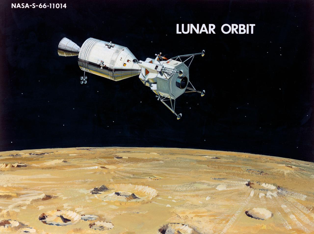
Artist Concepts, Apollo Mission: S66-10983: Ascent Stage Liftoff (S66-05094) S66-10984: Orientation During Ascent Phase (S66-05098) S66-10985: Midcourse Coast (S66-05113) S66-10986: Survey of Landing Site (S66-05117) S66-10987: Lunar Module (LM) Jettison (S66-05089) S66-10988: Trans-Earth Injection (S66-05090) S66-10989: Exploration on Lunar Surface Apollo Surface Lunar Exploration Experiment (ASLEP) S66-10990: Liftoff (S66-05125) S66-10991: Command Module (CM)-Service Module (SM) Separation (S66-05101 N/F) S66-10992: Touchdown on Lunar Surface (S66-05115) S66-10993: Transfer Orbit Insertion (S66-05111) S66-10994: Drogue Parachute Deployment S66-10995: S-IC Stage Separation S-II Stage Thrusting (S66-05099) S66-10996: Jettison Launch Escape System (S66-05114) S66-10997: Main Parachute Deployment (S66-05091) S66-10998: Mid-course correction (S66-05088) S66-10999: Lunar Orbit Insertion (S66-05086) S66-11000: Command Service Module (CSM)-LM Docked in LM Adapter-S-IVB (S66-06526) S66-11001: Docking and Separation of spacecraft from S-IVB (S66-05107) S66-11002: Final Descent (S66-05096) S66-11003: Entry into Earth Atmosphere (S66-05096) S66-11004: Deploy S/C LM Adapter-Separate CSM from LM-S-IVB (S66-06525 & 05105) S66-11005: Turnaround of CSM (S66-05104) S66-11006: S-II Stage Separation S-IVB Stage Thrusting (S66-05102) S66-11007: LM Ascent CSM Docked (S66-05100) S66-11008: Midcourse Correction SPS Mode (S66-05106) S66-11009: Earth Orbit Insertion of S-IVB & S/C (S66-05092) S66-11010: Trans-lunar Injection (S66-05116) S66-11011: LM Descent (S66-05110) S66-11012: S-IVB Stage Operations (S66-05112 N/F) S66-11013: Spacecraft Recovery (S66-05126) S66-11014: Lunar Orbit (S66-05103) S66-11015: CSM-LM Docking (S66-05095) S66-11016: Entry CM (S66-5109) S66-11017: Midcourse Corrections to Lunar Landing (S66-08486) S66-11018: Midcourse Corrections to Lunar Landing w/Overlay (S66-05083) S66-11019: Earth Launch Phase w/Overlay (S66-08485 & 05119) S66-11020: Earth Launch Phase (S66-08487 & S66-05084) S66-11022: Apollo Vehicles (S66-05127) S66-11024: Transfer to LM (S66-05082) S66-11025: Lunar Launch Phase S66-11027: Trans-earth Separation of C/M from S/M-C/M return to Earth (S66-05097) S66-11028: CSM-LM Separation, LM Descent to Moon (S66-05108) MSC, Houston, TX Also available in B&W 12/1965 - 06/1966
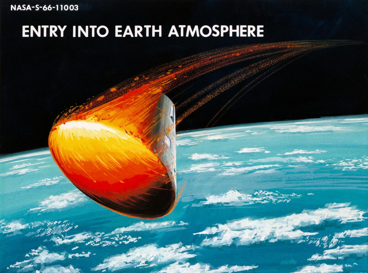
Artist Concepts, Apollo Mission: S66-10983: Ascent Stage Liftoff (S66-05094) S66-10984: Orientation During Ascent Phase (S66-05098) S66-10985: Midcourse Coast (S66-05113) S66-10986: Survey of Landing Site (S66-05117) S66-10987: Lunar Module (LM) Jettison (S66-05089) S66-10988: Trans-Earth Injection (S66-05090) S66-10989: Exploration on Lunar Surface Apollo Surface Lunar Exploration Experiment (ASLEP) S66-10990: Liftoff (S66-05125) S66-10991: Command Module (CM)-Service Module (SM) Separation (S66-05101 N/F) S66-10992: Touchdown on Lunar Surface (S66-05115) S66-10993: Transfer Orbit Insertion (S66-05111) S66-10994: Drogue Parachute Deployment S66-10995: S-IC Stage Separation S-II Stage Thrusting (S66-05099) S66-10996: Jettison Launch Escape System (S66-05114) S66-10997: Main Parachute Deployment (S66-05091) S66-10998: Mid-course correction (S66-05088) S66-10999: Lunar Orbit Insertion (S66-05086) S66-11000: Command Service Module (CSM)-LM Docked in LM Adapter-S-IVB (S66-06526) S66-11001: Docking and Separation of spacecraft from S-IVB (S66-05107) S66-11002: Final Descent (S66-05096) S66-11003: Entry into Earth Atmosphere (S66-05096) S66-11004: Deploy S/C LM Adapter-Separate CSM from LM-S-IVB (S66-06525 & 05105) S66-11005: Turnaround of CSM (S66-05104) S66-11006: S-II Stage Separation S-IVB Stage Thrusting (S66-05102) S66-11007: LM Ascent CSM Docked (S66-05100) S66-11008: Midcourse Correction SPS Mode (S66-05106) S66-11009: Earth Orbit Insertion of S-IVB & S/C (S66-05092) S66-11010: Trans-lunar Injection (S66-05116) S66-11011: LM Descent (S66-05110) S66-11012: S-IVB Stage Operations (S66-05112 N/F) S66-11013: Spacecraft Recovery (S66-05126) S66-11014: Lunar Orbit (S66-05103) S66-11015: CSM-LM Docking (S66-05095) S66-11016: Entry CM (S66-5109) S66-11017: Midcourse Corrections to Lunar Landing (S66-08486) S66-11018: Midcourse Corrections to Lunar Landing w/Overlay (S66-05083) S66-11019: Earth Launch Phase w/Overlay (S66-08485 & 05119) S66-11020: Earth Launch Phase (S66-08487 & S66-05084) S66-11022: Apollo Vehicles (S66-05127) S66-11024: Transfer to LM (S66-05082) S66-11025: Lunar Launch Phase S66-11027: Trans-earth Separation of C/M from S/M-C/M return to Earth (S66-05097) S66-11028: CSM-LM Separation, LM Descent to Moon (S66-05108) MSC, Houston, TX Also available in B&W 12/1965 - 06/1966
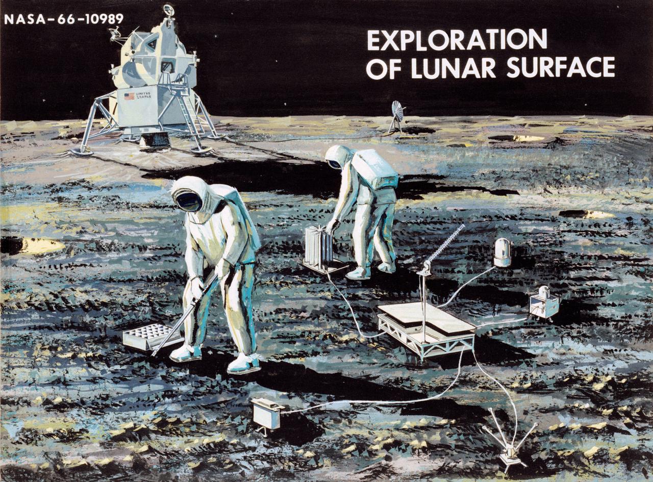
Artist Concepts, Apollo Mission: S66-10983: Ascent Stage Liftoff (S66-05094) S66-10984: Orientation During Ascent Phase (S66-05098) S66-10985: Midcourse Coast (S66-05113) S66-10986: Survey of Landing Site (S66-05117) S66-10987: Lunar Module (LM) Jettison (S66-05089) S66-10988: Trans-Earth Injection (S66-05090) S66-10989: Exploration on Lunar Surface Apollo Surface Lunar Exploration Experiment (ASLEP) S66-10990: Liftoff (S66-05125) S66-10991: Command Module (CM)-Service Module (SM) Separation (S66-05101 N/F) S66-10992: Touchdown on Lunar Surface (S66-05115) S66-10993: Transfer Orbit Insertion (S66-05111) S66-10994: Drogue Parachute Deployment S66-10995: S-IC Stage Separation S-II Stage Thrusting (S66-05099) S66-10996: Jettison Launch Escape System (S66-05114) S66-10997: Main Parachute Deployment (S66-05091) S66-10998: Mid-course correction (S66-05088) S66-10999: Lunar Orbit Insertion (S66-05086) S66-11000: Command Service Module (CSM)-LM Docked in LM Adapter-S-IVB (S66-06526) S66-11001: Docking and Separation of spacecraft from S-IVB (S66-05107) S66-11002: Final Descent (S66-05096) S66-11003: Entry into Earth Atmosphere (S66-05096) S66-11004: Deploy S/C LM Adapter-Separate CSM from LM-S-IVB (S66-06525 & 05105) S66-11005: Turnaround of CSM (S66-05104) S66-11006: S-II Stage Separation S-IVB Stage Thrusting (S66-05102) S66-11007: LM Ascent CSM Docked (S66-05100) S66-11008: Midcourse Correction SPS Mode (S66-05106) S66-11009: Earth Orbit Insertion of S-IVB & S/C (S66-05092) S66-11010: Trans-lunar Injection (S66-05116) S66-11011: LM Descent (S66-05110) S66-11012: S-IVB Stage Operations (S66-05112 N/F) S66-11013: Spacecraft Recovery (S66-05126) S66-11014: Lunar Orbit (S66-05103) S66-11015: CSM-LM Docking (S66-05095) S66-11016: Entry CM (S66-5109) S66-11017: Midcourse Corrections to Lunar Landing (S66-08486) S66-11018: Midcourse Corrections to Lunar Landing w/Overlay (S66-05083) S66-11019: Earth Launch Phase w/Overlay (S66-08485 & 05119) S66-11020: Earth Launch Phase (S66-08487 & S66-05084) S66-11022: Apollo Vehicles (S66-05127) S66-11024: Transfer to LM (S66-05082) S66-11025: Lunar Launch Phase S66-11027: Trans-earth Separation of C/M from S/M-C/M return to Earth (S66-05097) S66-11028: CSM-LM Separation, LM Descent to Moon (S66-05108) MSC, Houston, TX Also available in B&W 12/1965 - 06/1966
Artist Concepts, Apollo Mission: S66-10983: Ascent Stage Liftoff (S66-05094) S66-10984: Orientation During Ascent Phase (S66-05098) S66-10985: Midcourse Coast (S66-05113) S66-10986: Survey of Landing Site (S66-05117) S66-10987: Lunar Module (LM) Jettison (S66-05089) S66-10988: Trans-Earth Injection (S66-05090) S66-10989: Exploration on Lunar Surface Apollo Surface Lunar Exploration Experiment (ASLEP) S66-10990: Liftoff (S66-05125) S66-10991: Command Module (CM)-Service Module (SM) Separation (S66-05101 N/F) S66-10992: Touchdown on Lunar Surface (S66-05115) S66-10993: Transfer Orbit Insertion (S66-05111) S66-10994: Drogue Parachute Deployment S66-10995: S-IC Stage Separation S-II Stage Thrusting (S66-05099) S66-10996: Jettison Launch Escape System (S66-05114) S66-10997: Main Parachute Deployment (S66-05091) S66-10998: Mid-course correction (S66-05088) S66-10999: Lunar Orbit Insertion (S66-05086) S66-11000: Command Service Module (CSM)-LM Docked in LM Adapter-S-IVB (S66-06526) S66-11001: Docking and Separation of spacecraft from S-IVB (S66-05107) S66-11002: Final Descent (S66-05096) S66-11003: Entry into Earth Atmosphere (S66-05096) S66-11004: Deploy S/C LM Adapter-Separate CSM from LM-S-IVB (S66-06525 & 05105) S66-11005: Turnaround of CSM (S66-05104) S66-11006: S-II Stage Separation S-IVB Stage Thrusting (S66-05102) S66-11007: LM Ascent CSM Docked (S66-05100) S66-11008: Midcourse Correction SPS Mode (S66-05106) S66-11009: Earth Orbit Insertion of S-IVB & S/C (S66-05092) S66-11010: Trans-lunar Injection (S66-05116) S66-11011: LM Descent (S66-05110) S66-11012: S-IVB Stage Operations (S66-05112 N/F) S66-11013: Spacecraft Recovery (S66-05126) S66-11014: Lunar Orbit (S66-05103) S66-11015: CSM-LM Docking (S66-05095) S66-11016: Entry CM (S66-5109) S66-11017: Midcourse Corrections to Lunar Landing (S66-08486) S66-11018: Midcourse Corrections to Lunar Landing w/Overlay (S66-05083) S66-11019: Earth Launch Phase w/Overlay (S66-08485 & 05119) S66-11020: Earth Launch Phase (S66-08487 & S66-05084) S66-11022: Apollo Vehicles (S66-05127) S66-11024: Transfer to LM (S66-05082) S66-11025: Lunar Launch Phase S66-11027: Trans-earth Separation of C/M from S/M-C/M return to Earth (S66-05097) S66-11028: CSM-LM Separation, LM Descent to Moon (S66-05108) MSC, Houston, TX Also available in B&W 12/1965 - 06/1966

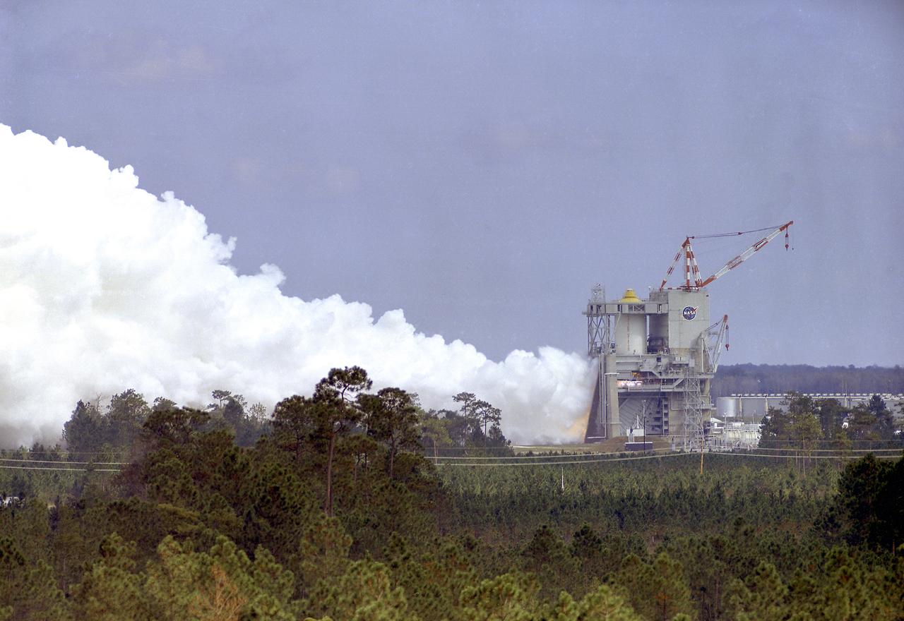
A space shuttle main engine test April 21, 2006, at NASA Stennis Space Center marked the 40th anniversary of the first rocket engine test at the site. The firing also marked the 25th anniversary of NASA's STS-1, the first space shuttle mission. Then called the Mississippi Test Facility, the center conducted its first test on April 23, 1966. That historic test was on an S-II (second) stage, a cluster of five J-2 engines that powered the Saturn V rockets that took America's Apollo missions to the moon.
The Saturn I S-I stages for the SA-8 and SA-10 mission in final assembly phase in a manufacturing building at the Michoud Assembly Facility in New Orleans, Louisiana. The SA-8 mission was launched on May 25, 1965 with the first industry-built booster, and deployed the Pegasus II Micrometeoroid Detection satellite. The SA-10 mission was the last Saturn I mission, launched on July 30, 1965, and carried the Pegasus III Meteoroid Detection satellite.
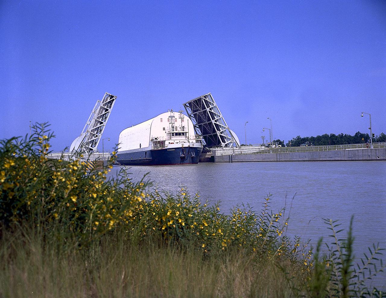
NASA used barges for transporting full-sized stages for the Saturn I, Saturn IB, and Saturn V vehicles between the Marshall Space Flight Center (MSFC), the manufacturing plant at the Michoud Assembly Facility (MAF), the Mississippi Test Facility for testing, and the Kennedy Space Center. The barges traveled from the MSFC dock to the MAF, a total of 1,086.7 miles up the Tennessee River and down the Mississippi River. The barges also transported the assembled stages of the Saturn vehicle from the MAF to the Kennedy Space Center, a total of 932.4 miles along the Gulf of Mexico and up along the Atlantic Ocean, for the final assembly and the launch. This photograph shows the barge Poseidon loaded with the Saturn V S-II (second) stage passing through a bascule bridge.
This photograph shows the Saturn-I first stage (S-1 stage) being transported to the test stand for a static test firing at the Marshall Space Flight Center. Soon after NASA began operations in October 1958, it was evident that sending people and substantial equipment beyond the Earth's gravitational field would require launch vehicles with weight-lifting capabilities far beyond any developed to that time. In early 1959, NASA accepted the proposal of Dr. Wernher von Braun for a multistage rocket, with a number of engines clustered in one or more of the stages to provide a large total thrust. The initiation of the Saturn launch vehicle program ultimately led to the study and preliminary plarning of many different configurations and resulted in production of three Saturn launch vehicles, the Saturn-I, Saturn I-B, and Saturn V. The Saturn family of launch vehicles began with the Saturn-I, a two-stage vehicle originally designated C-1. The research and development program was planned in two phases, or blocks: one for first stage development (Block I) and the second for both first and second stage development (Block-II). Saturn I had a low-earth-orbit payload capability of approximately 25,000 pounds. The design of the first stage (S-1 stage) used a cluster of propellant tanks containing liquid oxygen (LOX) and kerosene (RP-1), and eight H-1 engines, yielding a total thrust of 1,500,000 pounds. Of the ten Saturn-Is planned, the first eight were designed and built at the Marshall Space Flight Center, and the remaining two were built by the Chrysler Corporation.
What better way to mark 50 years of rocket engine testing than with a rocket engine test? Stennis Space Center employees enjoyed a chance to view an RS-68 engine test at the B-1 Test Stand on April 19, almost 50 years to the day that the first test was conducted at the south Mississippi site in 1966. The test viewing was part of a weeklong celebration of the 50th year of rocket engine testing at Stennis. The first test at the site occurred April 23, 1966, with a 15-second firing of a Saturn V second stage prototype (S-II-C) on the A-2 Test Stand. The center subsequently tested Apollo rocket stages that carried humans to the moon and every main engine used to power 135 space shuttle missions. It currently tests engines for NASA’s new Space Launch System vehicle.
The third stage (S-IVB) of the Saturn V launch vehicle for the Apollo 11 lunar landing mission is hoisted in the vehicle assembly building at the NASA Kennedy Space Center (KSC) for mating with the second stage (S-II). The vehicle, designated as AS-506, projected the first lunar landing mission, Apollo 11, on a trajectory for the Moon. The Apollo 11 mission launched from KSC in Florida via the Marshall Space Flight Center (MSFC) developed Saturn V launch vehicle on July 16, 1969 and safely returned to Earth on July 24, 1969. Astronauts onboard included Neil A. Armstrong, commander; Michael Collins, Command Module (CM) pilot; and Edwin E. Aldrin, Jr., Lunar Module (LM) pilot. The CM, “Columbia”, piloted by Collins, remained in a parking orbit around the Moon while the LM, “Eagle’’, carrying astronauts Armstrong and Aldrin, landed on the Moon. On July 20, 1969, Armstrong was the first human to ever stand on the lunar surface, followed by Aldrin. During 2½ hours of surface exploration, the crew collected 47 pounds of lunar surface material for analysis back on Earth. With the success of Apollo 11, the national objective to land men on the Moon and return them safely to Earth had been accomplished.
This artist's concept depicts the separation of the Skylab payload shroud. The payload shroud was both an environmental shield and an aerodynamic fairing. Attached to the forward end of the fixed airlock shroud, it protected the airlock, the docking adapter, and the solar observatory before and during launch. It also provided structural support for the solar observatory in the launch configuration. The payload shroud was jettisoned once Skylab reached orbit after separation of the S-II second stage of the Saturn V vehicle. Five major assemblies clustered together made up the orbiting space station called Skylab. The largest of these was the orbital workshop, that housed the crew quarters and a major experiment area. The airlock module, attached to the forward end of the workshop, enabled crewmembers to make excursions outside Skylab. The docking adapter, attached to the forward end of the airlock module, provided the docking port for the Apollo command and service module. The Apollo Telescope Mount was the first marned astronomical observatory designed for solar research from Earth orbit.

This is an illustration of the Space Base concept. In-house work of the Marshall Space Flight Center, as well as a Phase B contract with the McDornel Douglas Astronautics Company, resulted in a preliminary design for a space station in 1969 and l970. The Marshall-McDonnel Douglas approach envisioned the use of two common modules as the core configuration of a 12-man space station. Each common module was 33 feet in diameter and 40 feet in length and provided the building blocks, not only for the space station, but also for a 50-man space base. Coupled together, the two modules would form a four-deck facility: two decks for laboratories and two decks for operations and living quarters. Zero-gravity would be the normal mode of operation, although the station would have an artificial-gravity capability. This general-purpose orbital facility was to provide wide-ranging research capabilities. The design of the facility was driven by the need to accommodate a broad spectrum of activities in support of astronomy, astrophysics, aerospace medicine, biology, materials processing, space physics, and space manufacturing. To serve the needs of Earth observations, the station was to be placed in a 242-nautical-mile orbit at a 55-degree inclination. An Intermediate-21 vehicle (comprised of Saturn S-IC and S-II stages) would have launched the station in 1977.
This picture illustrates a concept of a 33-Foot-Diameter Space Station Leading to a Space Base. In-house work of the Marshall Space Flight Center, as well as a Phase B contract with the McDornel Douglas Astronautics Company, resulted in a preliminary design for a space station in 1969 and l970. The Marshall-McDonnel Douglas approach envisioned the use of two common modules as the core configuration of a 12-man space station. Each common module was 33 feet in diameter and 40 feet in length and provided the building blocks, not only for the space station, but also for a 50-man space base. Coupled together, the two modules would form a four-deck facility: two decks for laboratories and two decks for operations and living quarters. Zero-gravity would be the normal mode of operation, although the station would have an artificial gravity capability. This general-purpose orbital facility was to provide wide-ranging research capabilities. The design of the facility was driven by the need to accommodate a broad spectrum of activities in support of astronomy, astrophysics, aerospace medicine, biology, materials processing, space physics, and space manufacturing. To serve the needs of Earth observations, the station was to be placed in a 242-nautical-mile orbit at a 55-degree inclination. An Intermediate-21 vehicle (comprised of Saturn S-IC and S-II stages) would have launched the station in 1977.
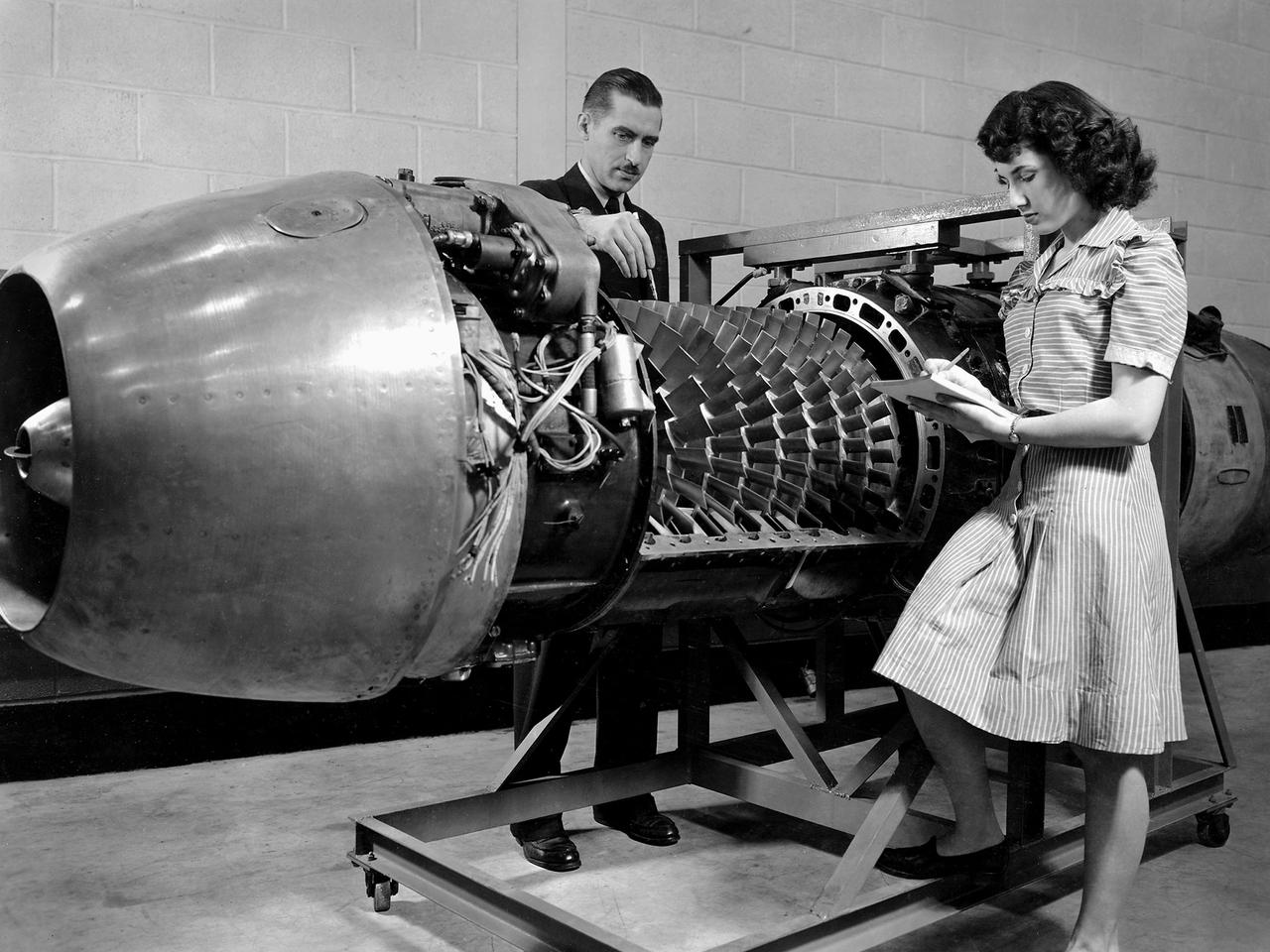
A General Electric TG-180 turbojet installed in the Altitude Wind Tunnel at the National Advisory Committee for Aeronautics (NACA) Lewis Flight Propulsion Laboratory. In 1943 the military asked General Electric to develop an axial-flow jet engine which became the TG-180. The military understood that the TG-180 would not be ready during World War II but recognized the axial-flow compressor’s long-term potential. Although the engine was bench tested in April 1944, it was not flight tested until February 1946. The TG-180 was brought to the Altitude Wind Tunnel in 1945 for a series of investigations. The studies, which continued intermittently into 1948, analyzed an array of performance issues. NACA modifications steadily improved the TG-180’s performance, including the first successful use of an afterburner. The Lewis researchers studied a 29-inch diameter afterburner over a range of altitude conditions using several different types of flameholders and fuel systems. Lewis researchers concluded that a three-stage flameholder with its largest stage upstream was the best burner configuration. Although the TG-180 (also known as the J35) was not the breakthrough engine that the military had hoped for, it did power the Douglas D-558-I Skystreak to a world speed record on August 20, 1947. The engines were also used on the Republic F-84 Thunderjet and the Northrup F-89 Scorpion.
Researcher Robert Miller led an investigation into the combustor performance of a German Jumo 004 engine at the National Advisory Committee for Aeronautics (NACA) Lewis Flight Propulsion Laboratory. The Jumo 004 powered the world's first operational jet fighter, the Messerschmitt Me 262, beginning in 1942. The Me 262 was the only jet aircraft used in combat during World War II. The eight-stage axial-flow compressor Jumo 004 produced 2000 pounds of thrust. The US Army Air Forces provided the NACA with a Jumo 004 engine in 1945 to study the compressor’s design and performance. Conveniently the engine’s designer Anselm Franz had recently arrived at Wright-Patterson Air Force Base in nearby Dayton, Ohio as part of Project Paperclip. The Lewis researchers used a test rig in the Engine Research Building to analyze one of the six combustion chambers. It was difficult to isolate a single combustor’s performance when testing an entire engine. The combustion efficiency, outlet-temperature distribution, and total pressure drop were measured. The researchers determined the Jumo 004’s maximum performance was 5000 revolutions per minute at a 27,000 foot altitude and 11,000 revolutions per minute at a 45,000 foot altitude. The setup in this photograph was created for a tour of NACA Lewis by members of the Institute of Aeronautical Science on March 22, 1945.
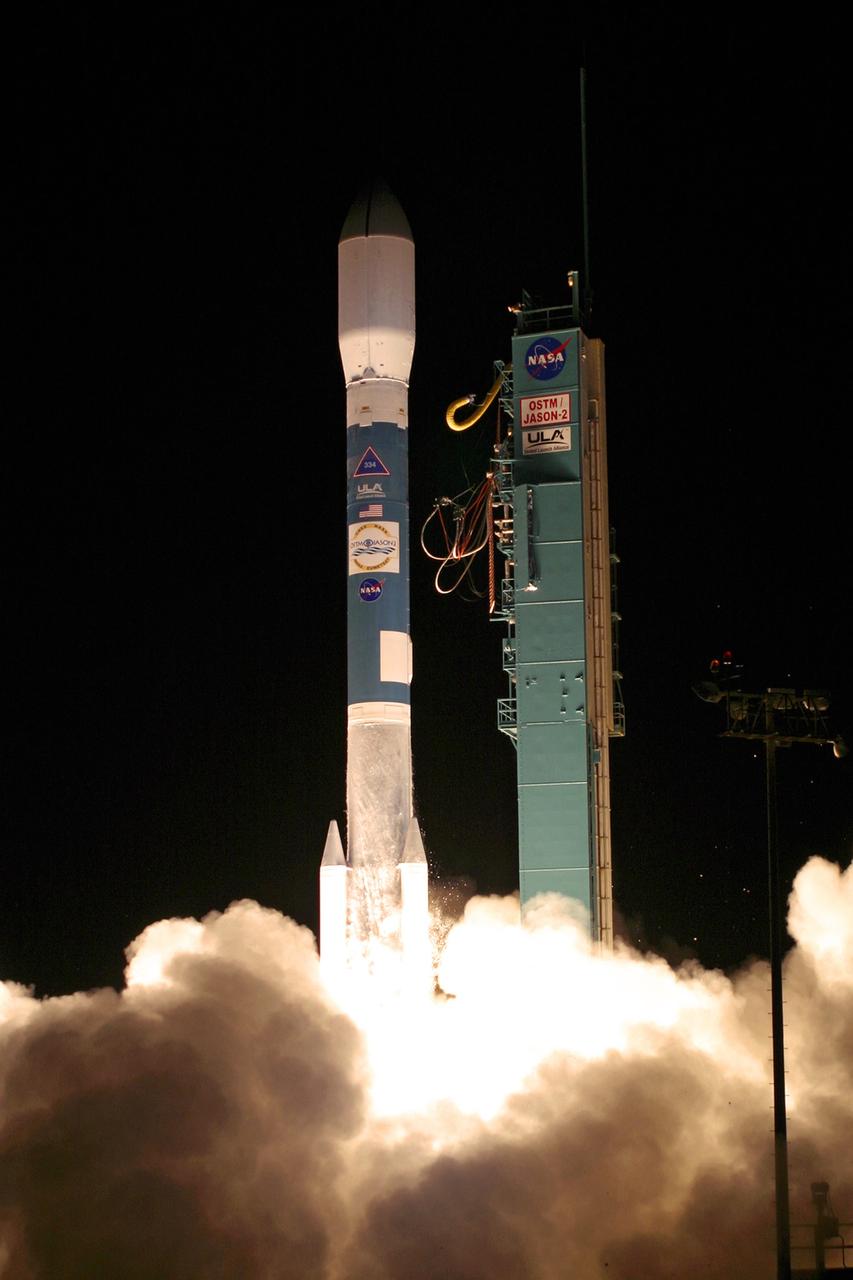
PASADENA, Calif. – The NASA-French space agency Ocean Surface Topography Mission/Jason 2 satellite launched aboard a Delta II rocket from Space Launch Complex 2 at Vandenberg Air Force Base, Calif., at 12:46 a.m. PDT. Fifty-five minutes later, OSTM/Jason 2 separated from the rocket’s second stage, and then, unfurled its twin sets of solar arrays. The OSTM/Jason 2 satellite will embark on a globe-circling voyage to continue charting sea level, a vital indicator of global climate change. The mission will return a vast amount of new data that will improve weather, climate and ocean forecasts. OSTM/Jason 2's expected lifetime of at least three years will extend into the next decade the continuous record of these data started in 1992 by NASA and the French space agency Centre National d'Etudes Spatiales, or CNES, with the TOPEX/Poseidon mission. The data collection was continued by the two agencies on Jason 1 in 2001. Photo credit: Carleton Bailie photograph for United Launch Alliance

This image from March 2, 1959 shows engineers from NASA's Jet Propulsion Laboratory checking NASA's Pioneer 4 spacecraft, the gold-and-black-colored cone sitting atop the white fourth-stage motor of the Juno II launch vehicle in Florida. Launched on March 3, 1959, NASA's Pioneer 4 was the first American mission to escape Earth orbit and the second of two early attempts by the United States to send a spacecraft to the Moon. The spacecraft achieved its primary objective — to put itself on a trajectory from Earth to the Moon. While it flew farther away from the Moon than expected and didn't take the images of the Moon as intended, Pioneer 4 did provide extensive and valuable data on Earth's radiation belt and the tracking of space objects. After 82 hours of transmissions from Pioneer 4's tiny radio and 655,000 miles (1.05 million kilometers) of travel — the farthest tracking distance for a human-made object at the time — contact is lost on March 6, 1959. Pioneer 4 is still in orbit around the Sun. The mission was carried out while JPL was transitioning from being part of the Army Ballistic Missile Agency to NASA. It marked the end of the U.S. Army's pioneering space program and the beginning of NASA's lunar program. JPL, in Pasadena, California, was responsible for mission design and management for both agencies. More information about Pioneer 4 can be found at: https://solarsystem.nasa.gov/missions/pioneer-4/in-depth/ https://photojournal.jpl.nasa.gov/catalog/PIA23497