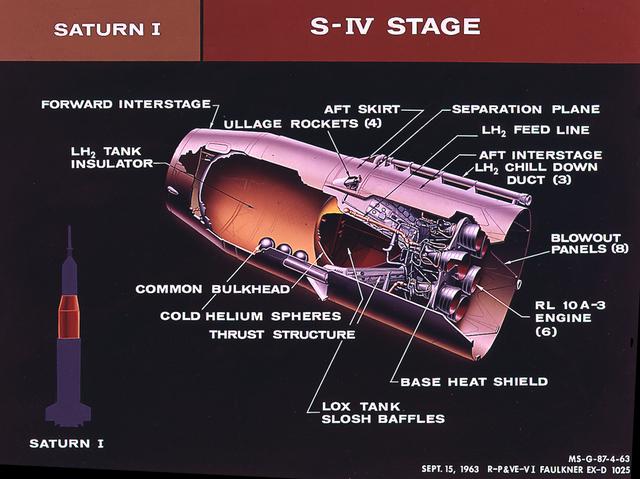
This cutaway of the Saturn I S-IV stage (second stage) illustrates the booster's components. Powered by six RL-10 engines, the S-IV stage was capable of producing 90,000 pounds of thrust. Development of the Saturn S-IV stage by the Marshall Space Flight Center (MSFC) contributed many technological breakthroughs vital to the success of the Apollo lunar program, including the use of liquid hydrogen as a propellant.
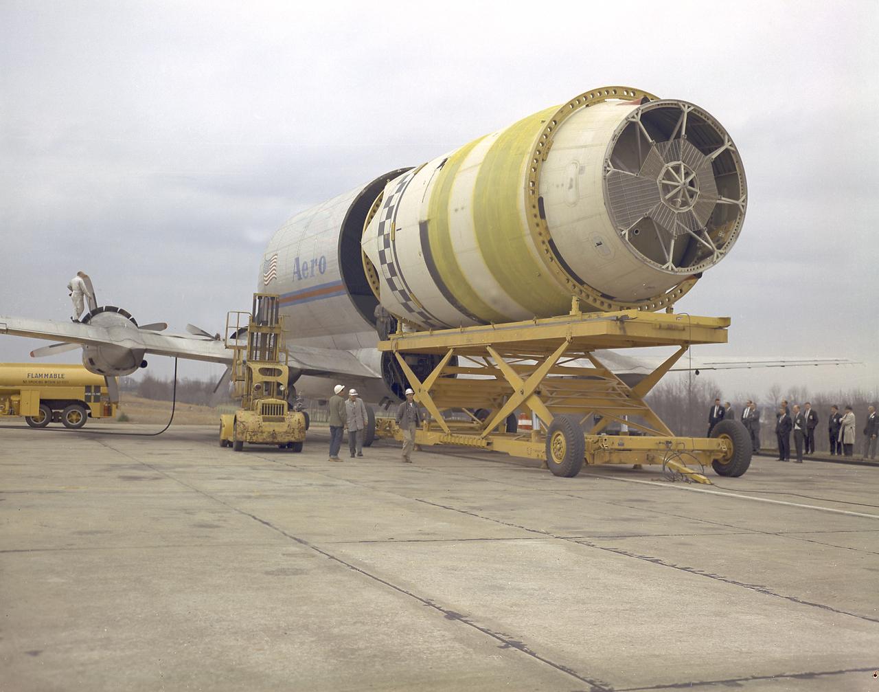
The photograph shows the loading operation of the Saturn I S-IV stage (second stage) into the Pregnant Guppy at the Redstone Airfield, Huntsville, Alabama. The Pregnant Guppy was a Boeing B-377 Stratocruiser modified to transport various stages of Saturn launch vehicles. The modification project called for lengthening the fuselage to accommodate the S-IV stage. After the flight test of that modification, phase two called for the enlargement of the plane's cabin section to approximately double its normal volume. The fuselage separated just aft of the wing's trailing edge to load and unload the S-IV and other cargoes.
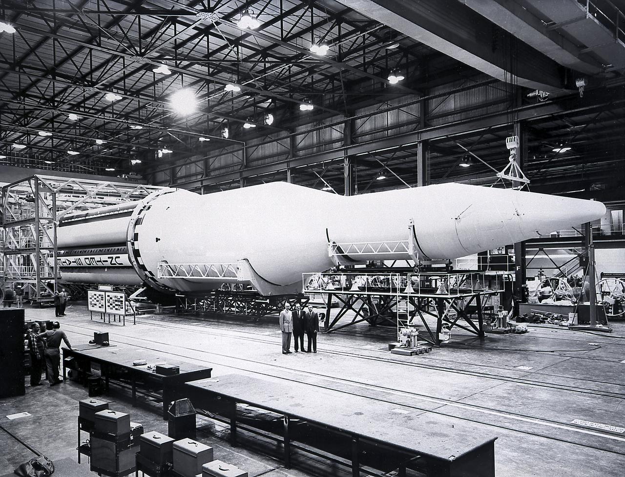
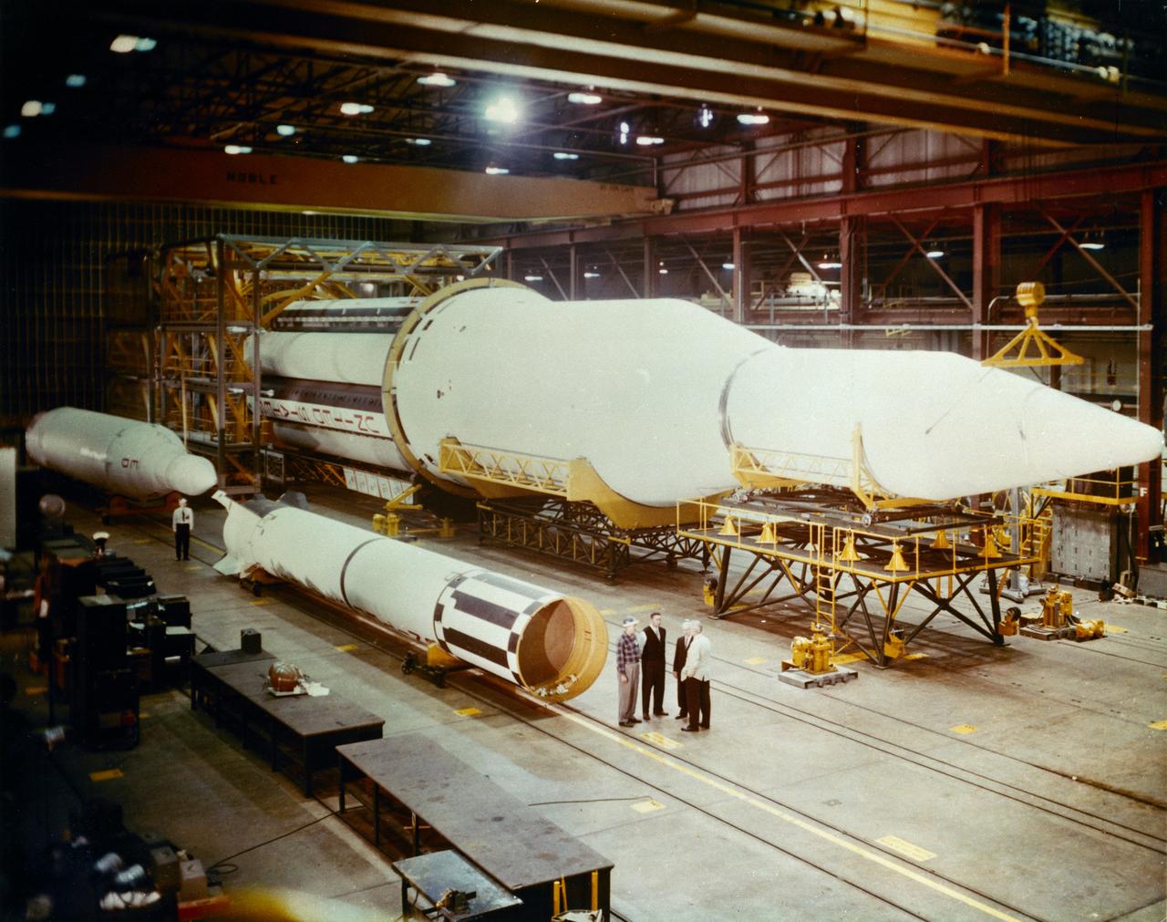
A completed Saturn I launch vehicle in the Fabrication and Assembly Engineering Division at the Marshall Space Flight Center. The Saturn I launch vehicle is composed of an S-I first stage or booster (rear), powered by eight H-1 engines having a thrust of 1,500,000 pounds, followed by a dummy S-IV second stage with six RL-10 engine, with a total thrust of 90,000 pounds.
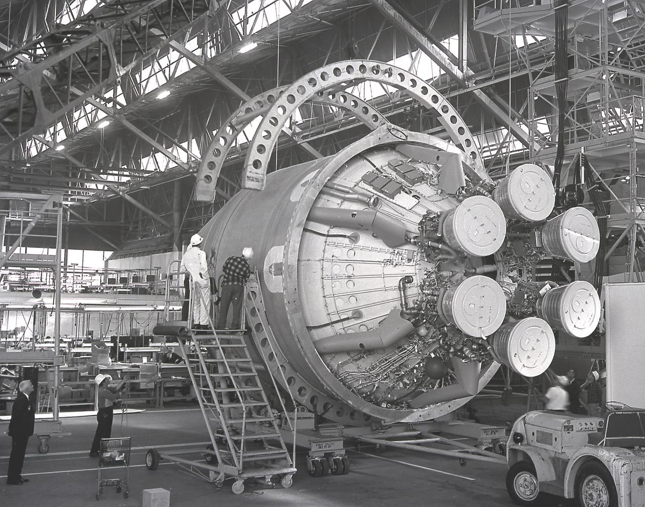
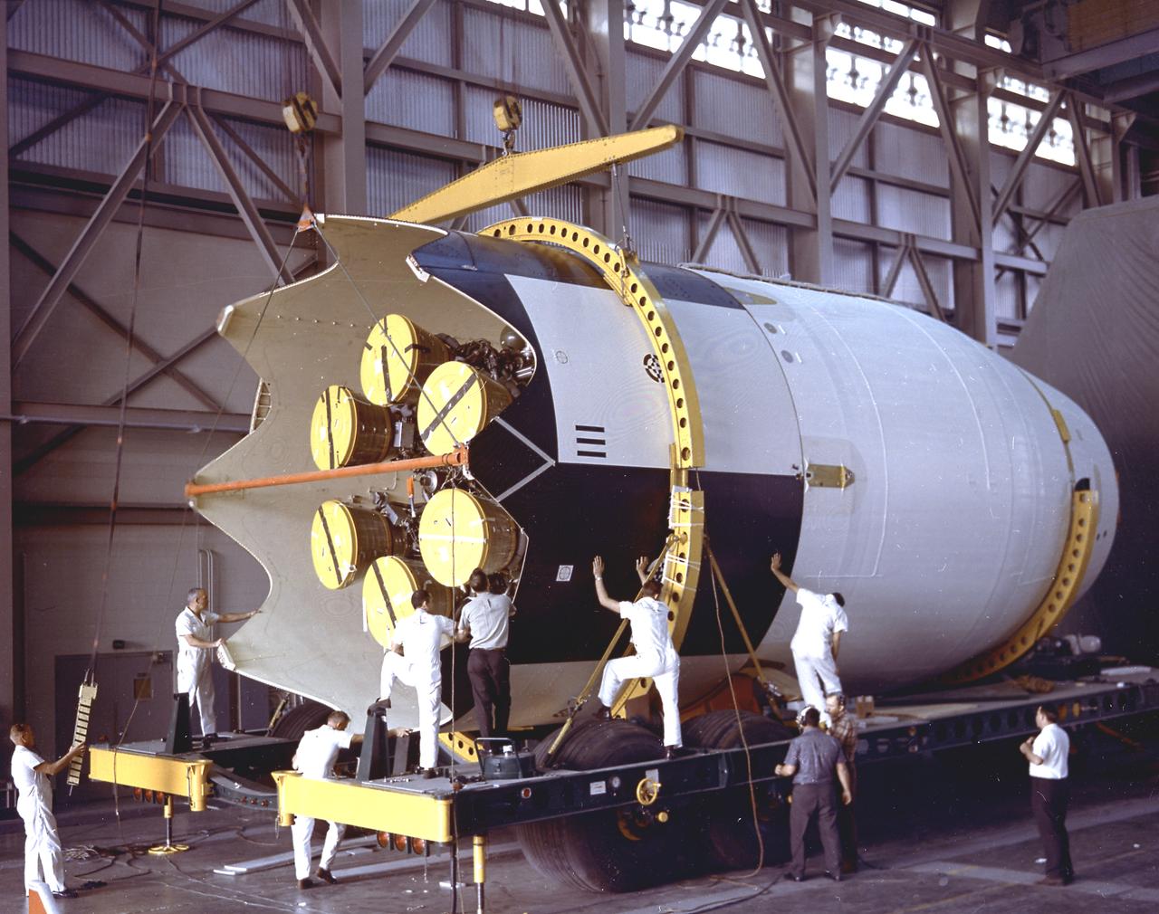
The Saturn I S-IV stage (second stage) for the SA-7 mission being prepared for shipment to Cape Canaveral, Florida. The S-IV stage had six RL-10 engines, which used liquid hydrogen and liquid oxygen as its propellants, arranged in a circle. Each RL-10 engine produced a thrust of 15,000 pounds for a total combined thrust of 90,000 pounds. The SA-7 mission was launched on September 18, 1964 from Cape Canaveral, Florida, and its S-IV stage made the second orbital flight.
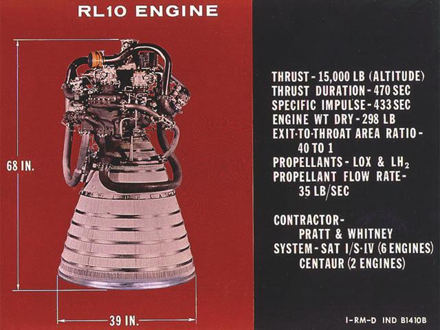
RL-10 engine characteristics. The RL-10 engine was developed under the management of the Marshall Space Flight Center (MSFC) to power the Saturn I upper stage (S-IV stage). The six RL-10 engines, which used liquid hydrogen and liquid oxygen as propellants, were arranged in a circle on the aft end of the S-IV stage.
The Saturn I S-IV stage (second stage) assembly for the SA-9 mission underwent the weight and balance test in the hangar building at Cape Canaveral. The S-IV stage had six RL-10 engines which used liquid hydrogen and liquid oxygen as its propellants arranged in a circle. Each RL-10 engine produced a thrust of 15,000 pounds, a total combined thrust of 90,000 pounds. The SA-9 mission was the first Saturn with operational payload Pegasus I, meteoroid detection satellite, and launched on February 16, 1965.
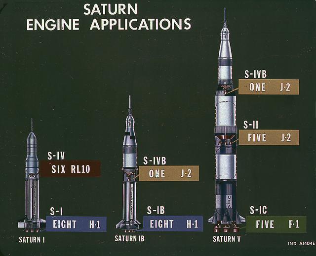
This image illustrates the basic differences between the three Saturn launch vehicles developed by the Marshall Space Flight Center. The Saturn I, consisted of two stages, the S-I (eight H-1 engines) and the S-IV (six RL-10 engines). The Saturn IB (center) also consisted of two stages, the S-IB (eight H-1 engines) and the S-IVB (one J-2 engine). The Saturn V consisted of three stages, the S-IC (five F-1 engines), the S-II (five J-2 engines), and the S-IVB (one J-2 engine).
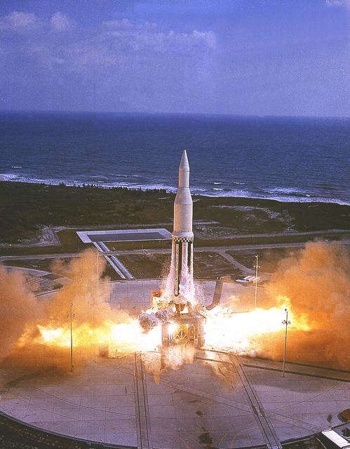
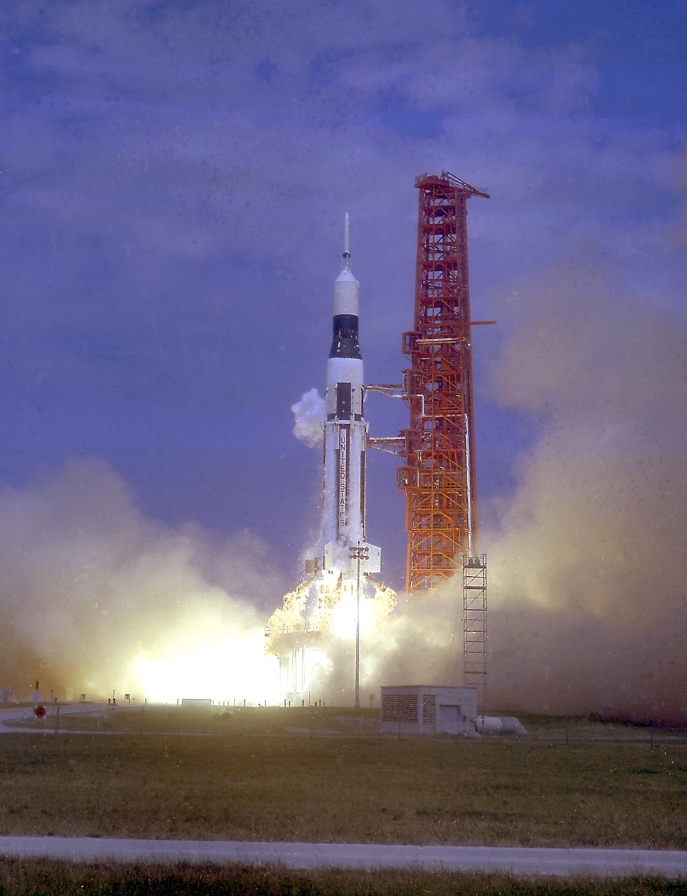
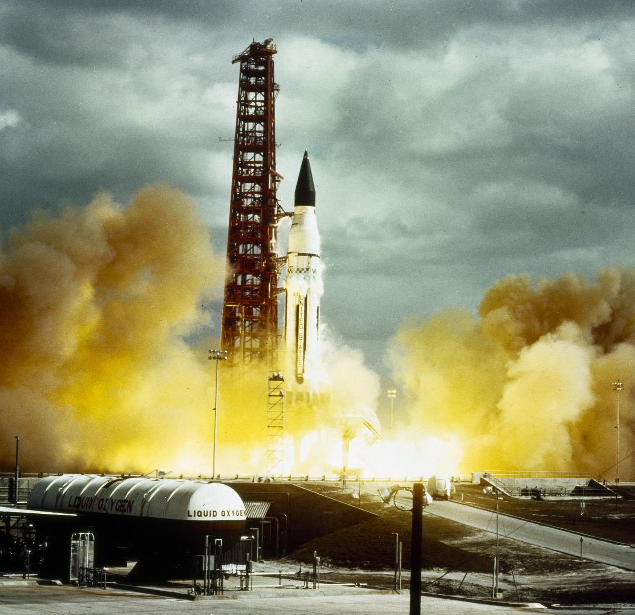
The Marshall Space Flight Center's first Saturn I vehicle, SA-1, lifts off from Cape Canaveral, Florida, on October 27, 1961. This early configuration, Saturn I Block I, 162 feet tall and weighing 460 tons, consisted of the eight H-1 engines S-I stage and the dummy second stage (S-IV stage).
The launch of the SA-7 (Saturn I Block II) was on September 18, 1964. The SA-7 mission was the second orbital flight of the S-IV stage (second stage) with the payload consisting of the Apollo command and service module's instrument unit. The Saturn I Block II vehicle had two live stages, and were basically in the two-stage configuration of the Saturn I vehicle. While the tank arrangement and the engine patterns were the same, there were marked changes between the Block I and II versions. The first stage (S-I stage) was an improved version of the Block I S-I stage. The Block II S-1 stage had eight fins added for greater aerodynamic stability in the lower atmosphere.
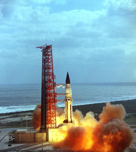
The launch of the SA-5 on January 29, 1964 was the fifth Saturn I launch vehicle. The SA-5 marked a number of firsts in the Marshall Space Flight Center-managed Saturn development program, including the first flight of Saturn I Block II vehicle with eight aerodynamic fins at the bottom of the S-I stage (first stage) for enhanced stability in flight. This also was the first flight of a live S-IV (second or upper) stage with the cluster of six liquid hydrogen-fueled RL-10 engines. the first successful second stage separation, and the first use of the Launch Complex 37.
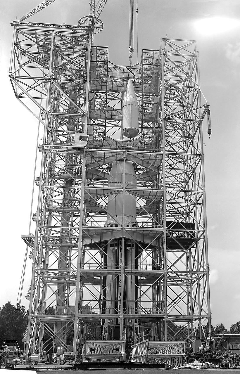
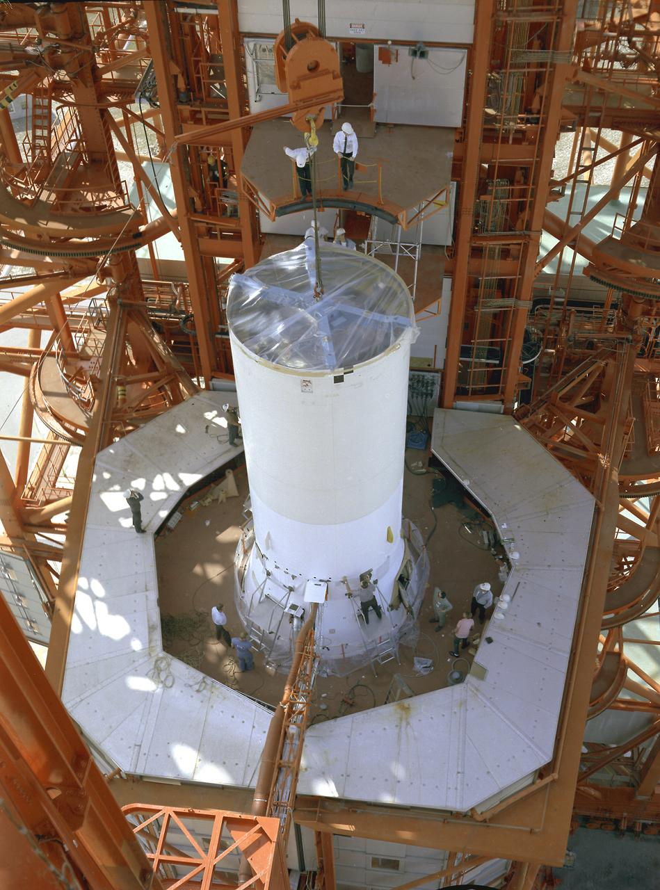
This image depicts the Saturn I launch vehicle placed in the dynamic test stand at the Marshall Space Flight Center (MSFC). A dummy booster was moved to the dynamic test stand early in June, and, for the first time, vertically mated with dummy S-I and S-IV stages. The assembled vehicle was readied for dynamic testing to investigate the integrity of the support structure.
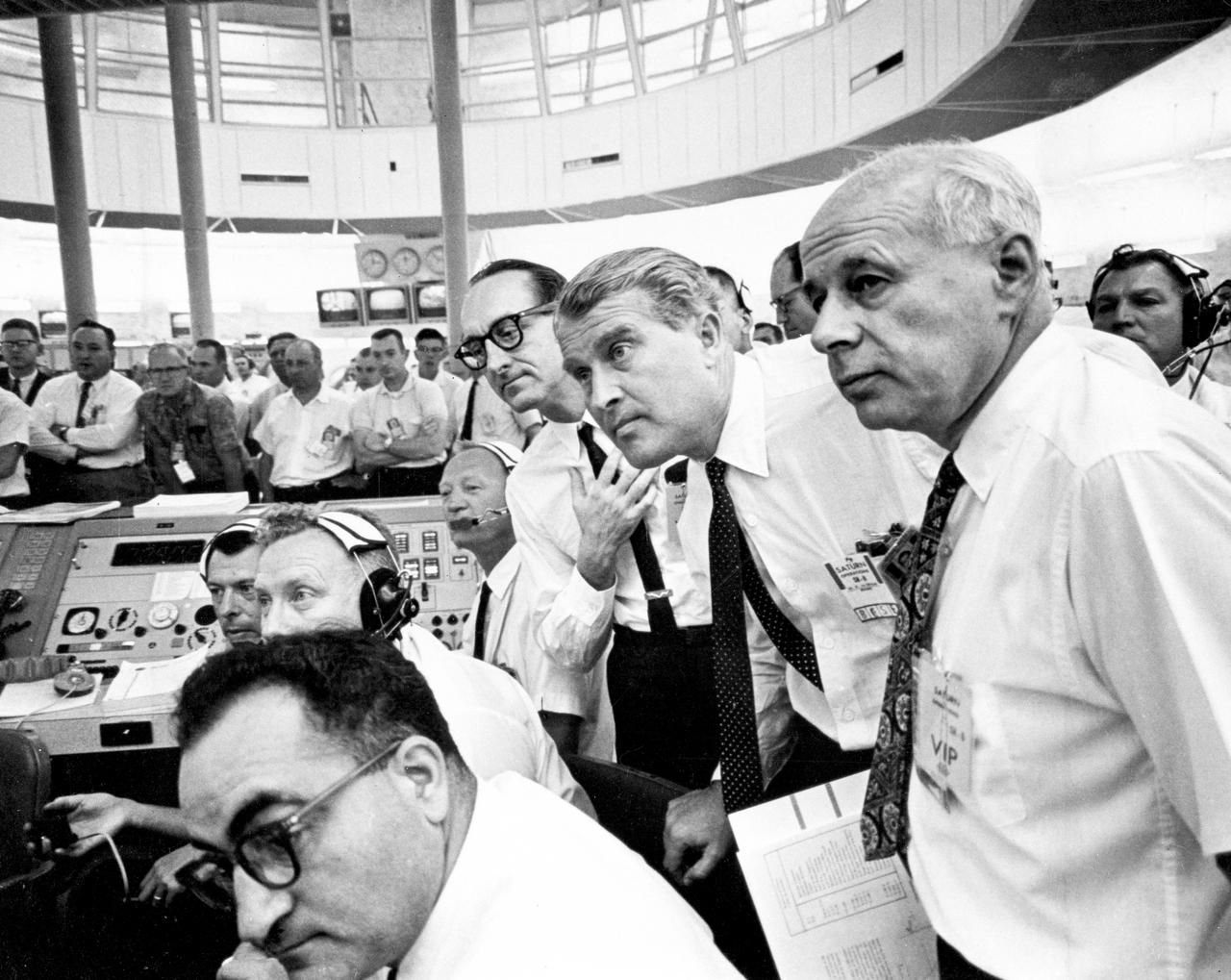
This photograph depicts an intense moment during the SA-6 launch at the Firing Room. Dr. von Braun, Director of the Marshall Space Flight Center (MSFC) is at center; to his left is Dr. George Mueller, Associate Director for Marned Space Flight; and far right is Dr. Eberhard Rees, Director for Research and Development, MSFC. The SA-6, the sixth flight of the Saturn 1 vehicle, launched a S-IV stage (a second stage) and an Apollo boilerplate spacecraft.
Progress in the Saturn program, depicted below, was described by Dr. Wernher von Braun, Marshall Space Flight Center (MSFC) Director, in an appearance before the Senate Committee of Aeronautical and Space Sciences. "The flight configuration of the giant three-stage Saturn C-1 rocket (later called Saturn I Block I) is seen in the Fabrication and Assembly Engineering Division at MSFC. Dwarfed by the 180-foot C-1 are a Juno II rocket (left rear) and a Mercury-Redstone rocket (front foreground). The C-1 (first version of the Saturn rocket) is composed of an S-1 first stage or booster (rear), powered by eight H-1 engines having a thrust of 1,500,000 pounds, followed by a dummy S-IV second stage and a dummy S-V third stage. The "live" S-IV for later flights, under development by Douglas Aircraft Co., will be powered by four Pratt Whitney LR-119 engines having 17,500,000 pounds thrust each. The live S-V, under development by Convair Division of General Dynamics Corp., will use two LR-119 engines. With all three stages live, the C-1 will be capable of placing 19,000 pounds into a 300-mile Earth orbit, sending 5,000 pounds to escape velocity, or lofting 2,500 pounds to Mars or Venus. The second version Saturn C-2 (later called Saturn 1 Block II) would double these capabilities. Early C-1 flights will employ a live S-1 with dummy upper stages. The first such flight is scheduled late this year."
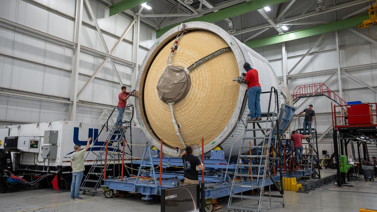
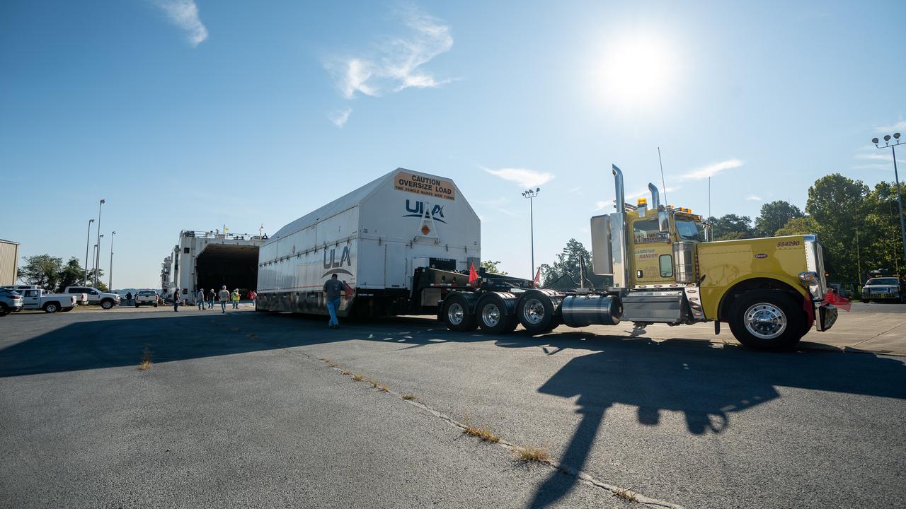
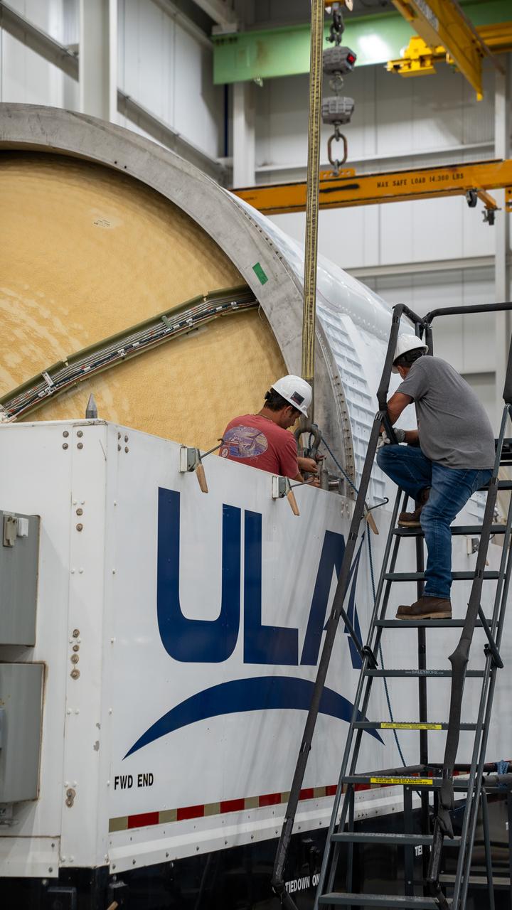
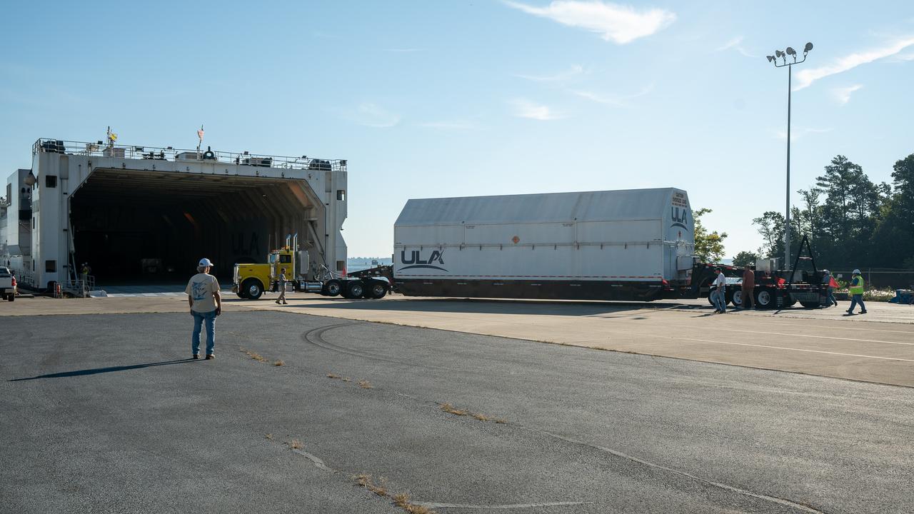
These images and videos show how crews in Alabama prepared the ICPS (interim cryogenic propulsion stage) for NASA’s SLS (Space Launch System) rocket for shipment to Florida between July 29-31. The ICPS in the photos and videos will help power NASA’s Artemis III mission to the Moon. The SLS upper stage is manufactured by United Launch Alliance at its facility in Decatur. Its RL10 engine is produced by Aerojet Rocketdyne, the SLS engines lead contractor, in West Palm Beach, Florida. ULA is working with Boeing, the SLS core stage and exploration upper stage lead contractor, to develop ICPS. ULA’s R/S RocketShip is transporting the flight hardware to its sister facility in Florida near NASA’s Kennedy Space Center for final checkouts. The ICPS for Artemis III is the last of its kind as SLS transitions to its next, more powerful Block 1B configuration with an upgraded upper stage beginning with Artemis IV. NASA is working to land the first woman and first person of color on the Moon under Artemis. SLS is part of NASA’s backbone for deep space exploration, along with Orion and the Gateway in orbit around the Moon. SLS is the only rocket that can send Orion, astronauts, and supplies to the Moon in a single mission.
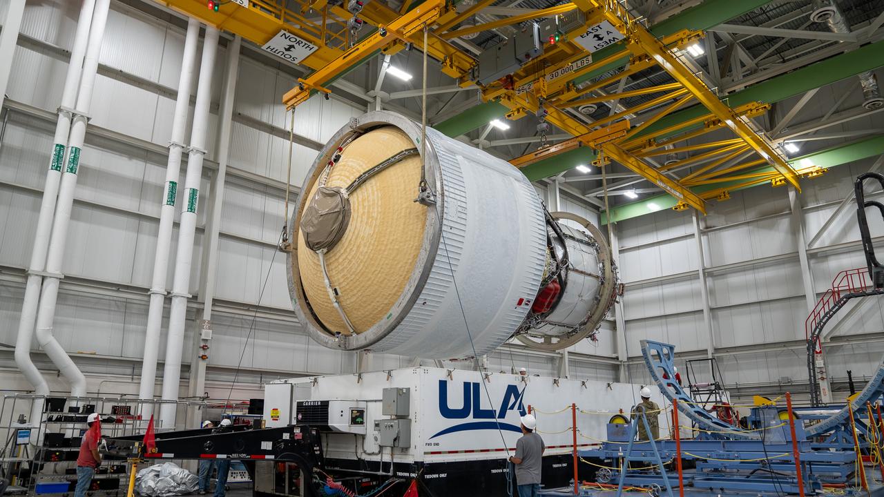
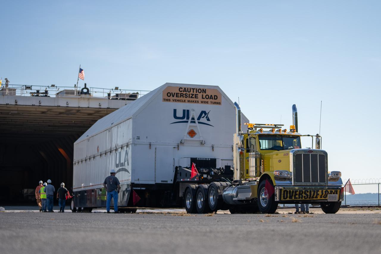
These images and videos show how crews in Alabama prepared the ICPS (interim cryogenic propulsion stage) for NASA’s SLS (Space Launch System) rocket for shipment to Florida between July 29-31. The ICPS in the photos and videos will help power NASA’s Artemis III mission to the Moon. The SLS upper stage is manufactured by United Launch Alliance at its facility in Decatur. Its RL10 engine is produced by Aerojet Rocketdyne, the SLS engines lead contractor, in West Palm Beach, Florida. ULA is working with Boeing, the SLS core stage and exploration upper stage lead contractor, to develop ICPS. ULA’s R/S RocketShip is transporting the flight hardware to its sister facility in Florida near NASA’s Kennedy Space Center for final checkouts. The ICPS for Artemis III is the last of its kind as SLS transitions to its next, more powerful Block 1B configuration with an upgraded upper stage beginning with Artemis IV. NASA is working to land the first woman and first person of color on the Moon under Artemis. SLS is part of NASA’s backbone for deep space exploration, along with Orion and the Gateway in orbit around the Moon. SLS is the only rocket that can send Orion, astronauts, and supplies to the Moon in a single mission.
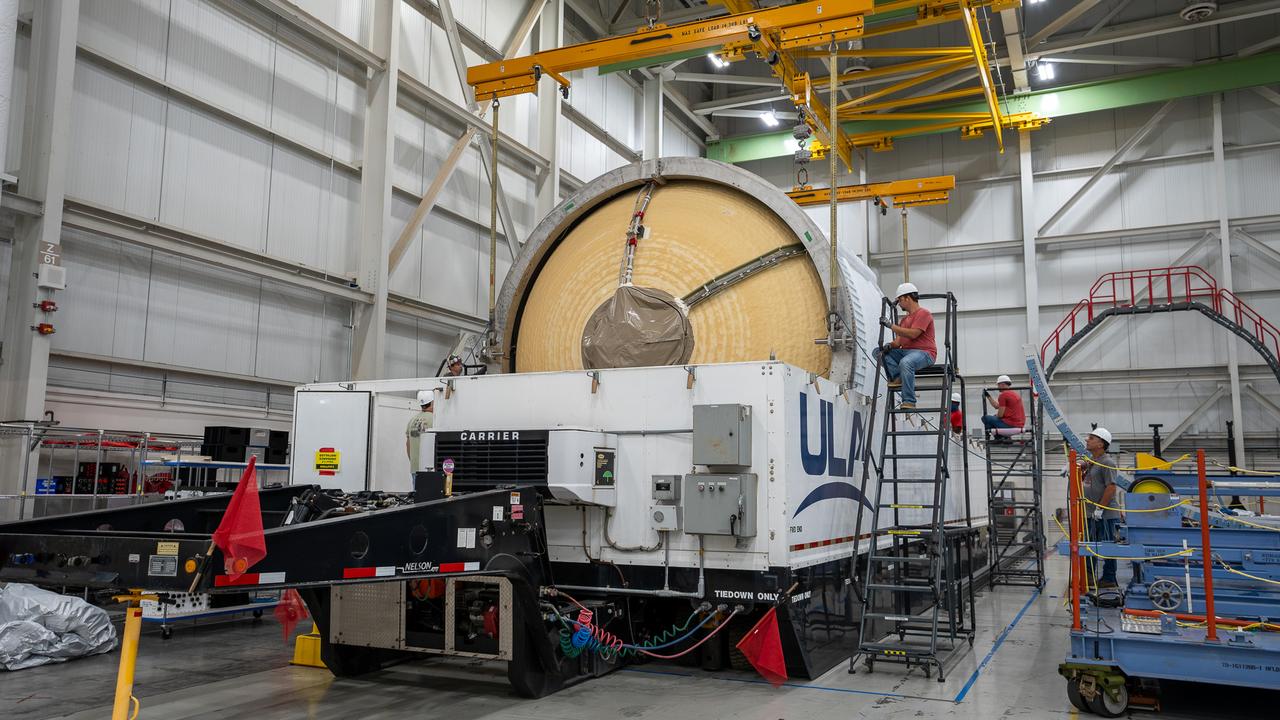
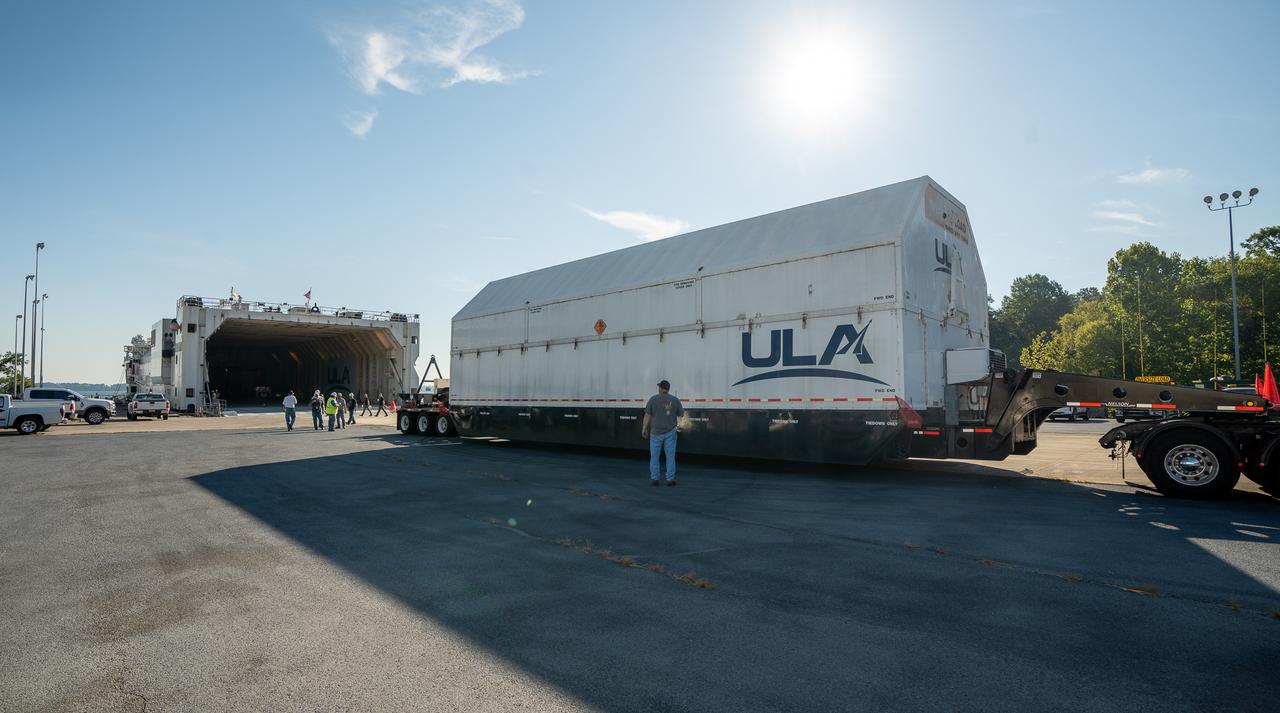
These images and videos show how crews in Alabama prepared the ICPS (interim cryogenic propulsion stage) for NASA’s SLS (Space Launch System) rocket for shipment to Florida between July 29-31. The ICPS in the photos and videos will help power NASA’s Artemis III mission to the Moon. The SLS upper stage is manufactured by United Launch Alliance at its facility in Decatur. Its RL10 engine is produced by Aerojet Rocketdyne, the SLS engines lead contractor, in West Palm Beach, Florida. ULA is working with Boeing, the SLS core stage and exploration upper stage lead contractor, to develop ICPS. ULA’s R/S RocketShip is transporting the flight hardware to its sister facility in Florida near NASA’s Kennedy Space Center for final checkouts. The ICPS for Artemis III is the last of its kind as SLS transitions to its next, more powerful Block 1B configuration with an upgraded upper stage beginning with Artemis IV. NASA is working to land the first woman and first person of color on the Moon under Artemis. SLS is part of NASA’s backbone for deep space exploration, along with Orion and the Gateway in orbit around the Moon. SLS is the only rocket that can send Orion, astronauts, and supplies to the Moon in a single mission.
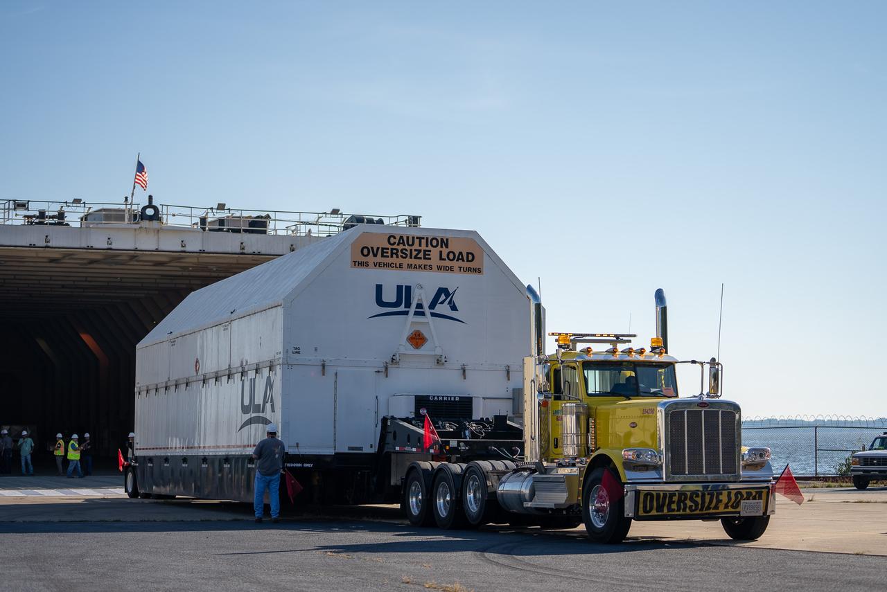
These images and videos show how crews in Alabama prepared the ICPS (interim cryogenic propulsion stage) for NASA’s SLS (Space Launch System) rocket for shipment to Florida between July 29-31. The ICPS in the photos and videos will help power NASA’s Artemis III mission to the Moon. The SLS upper stage is manufactured by United Launch Alliance at its facility in Decatur. Its RL10 engine is produced by Aerojet Rocketdyne, the SLS engines lead contractor, in West Palm Beach, Florida. ULA is working with Boeing, the SLS core stage and exploration upper stage lead contractor, to develop ICPS. ULA’s R/S RocketShip is transporting the flight hardware to its sister facility in Florida near NASA’s Kennedy Space Center for final checkouts. The ICPS for Artemis III is the last of its kind as SLS transitions to its next, more powerful Block 1B configuration with an upgraded upper stage beginning with Artemis IV. NASA is working to land the first woman and first person of color on the Moon under Artemis. SLS is part of NASA’s backbone for deep space exploration, along with Orion and the Gateway in orbit around the Moon. SLS is the only rocket that can send Orion, astronauts, and supplies to the Moon in a single mission.
These images and videos show how crews in Alabama prepared the ICPS (interim cryogenic propulsion stage) for NASA’s SLS (Space Launch System) rocket for shipment to Florida between July 29-31. The ICPS in the photos and videos will help power NASA’s Artemis III mission to the Moon. The SLS upper stage is manufactured by United Launch Alliance at its facility in Decatur. Its RL10 engine is produced by Aerojet Rocketdyne, the SLS engines lead contractor, in West Palm Beach, Florida. ULA is working with Boeing, the SLS core stage and exploration upper stage lead contractor, to develop ICPS. ULA’s R/S RocketShip is transporting the flight hardware to its sister facility in Florida near NASA’s Kennedy Space Center for final checkouts. The ICPS for Artemis III is the last of its kind as SLS transitions to its next, more powerful Block 1B configuration with an upgraded upper stage beginning with Artemis IV. NASA is working to land the first woman and first person of color on the Moon under Artemis. SLS is part of NASA’s backbone for deep space exploration, along with Orion and the Gateway in orbit around the Moon. SLS is the only rocket that can send Orion, astronauts, and supplies to the Moon in a single mission.
These images and videos show how crews in Alabama prepared the ICPS (interim cryogenic propulsion stage) for NASA’s SLS (Space Launch System) rocket for shipment to Florida between July 29-31. The ICPS in the photos and videos will help power NASA’s Artemis III mission to the Moon. The SLS upper stage is manufactured by United Launch Alliance at its facility in Decatur. Its RL10 engine is produced by Aerojet Rocketdyne, the SLS engines lead contractor, in West Palm Beach, Florida. ULA is working with Boeing, the SLS core stage and exploration upper stage lead contractor, to develop ICPS. ULA’s R/S RocketShip is transporting the flight hardware to its sister facility in Florida near NASA’s Kennedy Space Center for final checkouts. The ICPS for Artemis III is the last of its kind as SLS transitions to its next, more powerful Block 1B configuration with an upgraded upper stage beginning with Artemis IV. NASA is working to land the first woman and first person of color on the Moon under Artemis. SLS is part of NASA’s backbone for deep space exploration, along with Orion and the Gateway in orbit around the Moon. SLS is the only rocket that can send Orion, astronauts, and supplies to the Moon in a single mission.
These images and videos show how crews in Alabama prepared the ICPS (interim cryogenic propulsion stage) for NASA’s SLS (Space Launch System) rocket for shipment to Florida between July 29-31. The ICPS in the photos and videos will help power NASA’s Artemis III mission to the Moon. The SLS upper stage is manufactured by United Launch Alliance at its facility in Decatur. Its RL10 engine is produced by Aerojet Rocketdyne, the SLS engines lead contractor, in West Palm Beach, Florida. ULA is working with Boeing, the SLS core stage and exploration upper stage lead contractor, to develop ICPS. ULA’s R/S RocketShip is transporting the flight hardware to its sister facility in Florida near NASA’s Kennedy Space Center for final checkouts. The ICPS for Artemis III is the last of its kind as SLS transitions to its next, more powerful Block 1B configuration with an upgraded upper stage beginning with Artemis IV. NASA is working to land the first woman and first person of color on the Moon under Artemis. SLS is part of NASA’s backbone for deep space exploration, along with Orion and the Gateway in orbit around the Moon. SLS is the only rocket that can send Orion, astronauts, and supplies to the Moon in a single mission.

These images and videos show how crews in Alabama prepared the ICPS (interim cryogenic propulsion stage) for NASA’s SLS (Space Launch System) rocket for shipment to Florida between July 29-31. The ICPS in the photos and videos will help power NASA’s Artemis III mission to the Moon. The SLS upper stage is manufactured by United Launch Alliance at its facility in Decatur. Its RL10 engine is produced by Aerojet Rocketdyne, the SLS engines lead contractor, in West Palm Beach, Florida. ULA is working with Boeing, the SLS core stage and exploration upper stage lead contractor, to develop ICPS. ULA’s R/S RocketShip is transporting the flight hardware to its sister facility in Florida near NASA’s Kennedy Space Center for final checkouts. The ICPS for Artemis III is the last of its kind as SLS transitions to its next, more powerful Block 1B configuration with an upgraded upper stage beginning with Artemis IV. NASA is working to land the first woman and first person of color on the Moon under Artemis. SLS is part of NASA’s backbone for deep space exploration, along with Orion and the Gateway in orbit around the Moon. SLS is the only rocket that can send Orion, astronauts, and supplies to the Moon in a single mission.
These images and videos show how crews in Alabama prepared the ICPS (interim cryogenic propulsion stage) for NASA’s SLS (Space Launch System) rocket for shipment to Florida between July 29-31. The ICPS in the photos and videos will help power NASA’s Artemis III mission to the Moon. The SLS upper stage is manufactured by United Launch Alliance at its facility in Decatur. Its RL10 engine is produced by Aerojet Rocketdyne, the SLS engines lead contractor, in West Palm Beach, Florida. ULA is working with Boeing, the SLS core stage and exploration upper stage lead contractor, to develop ICPS. ULA’s R/S RocketShip is transporting the flight hardware to its sister facility in Florida near NASA’s Kennedy Space Center for final checkouts. The ICPS for Artemis III is the last of its kind as SLS transitions to its next, more powerful Block 1B configuration with an upgraded upper stage beginning with Artemis IV. NASA is working to land the first woman and first person of color on the Moon under Artemis. SLS is part of NASA’s backbone for deep space exploration, along with Orion and the Gateway in orbit around the Moon. SLS is the only rocket that can send Orion, astronauts, and supplies to the Moon in a single mission.
These images and videos show how crews in Alabama prepared the ICPS (interim cryogenic propulsion stage) for NASA’s SLS (Space Launch System) rocket for shipment to Florida between July 29-31. The ICPS in the photos and videos will help power NASA’s Artemis III mission to the Moon. The SLS upper stage is manufactured by United Launch Alliance at its facility in Decatur. Its RL10 engine is produced by Aerojet Rocketdyne, the SLS engines lead contractor, in West Palm Beach, Florida. ULA is working with Boeing, the SLS core stage and exploration upper stage lead contractor, to develop ICPS. ULA’s R/S RocketShip is transporting the flight hardware to its sister facility in Florida near NASA’s Kennedy Space Center for final checkouts. The ICPS for Artemis III is the last of its kind as SLS transitions to its next, more powerful Block 1B configuration with an upgraded upper stage beginning with Artemis IV. NASA is working to land the first woman and first person of color on the Moon under Artemis. SLS is part of NASA’s backbone for deep space exploration, along with Orion and the Gateway in orbit around the Moon. SLS is the only rocket that can send Orion, astronauts, and supplies to the Moon in a single mission.
Developed at MSFC under the direction of Dr. Wernher von Braun, the SA-5 incorporated a Saturn I, Block II engine. Launched on January 29, 1964, SA-5 was the first two stage (Block II) Saturn with orbital capability and performed the first test of Instrument Unit and successful stage separation. Block II vehicles had two live stages, and were basically in the two-stage configuration of the Saturn I vehicle. There were marked changes between the Block I and II versions. The Block II S-I stage had eight fins added for greater aerodynamic stability in the lower atmosphere. All Block II H-1 engines had a thrust of 188,000 pounds each for a combined thrust over 1,500,000 pounds. The Block II second stage (S-IV) had six RL-10 hydrogen-oxygen engines, each producing a thrust of 15,000 pounds for a total combined thrust of 90,000 pounds. A motion picture camera capsule loated on stage I was successful recovered.
Pegasus-1, meteoroid detection satellite, installed on Saturn I (SA-9 mission) S-IV stage, January 13, 1965. The satellite was used to obtain data on frequency and penetration of the potentially hazardous micrometeoroids in low Earth orbits and to relay the information back to Earth. SA-9 was launched on February 16, 1965 and the Pegasus-1 satellite was the first operational payload for Saturn I.
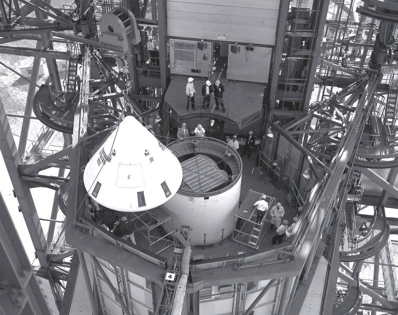
In this photograph, the Pegasus, meteoroid detection satellite is installed in its specially modified Apollo service module atop the S-IV stage (second stage) of a Saturn I vehicle for the SA-9 mission at Cape Kennedy. Personnel in the service structure moved the boilerplate Apollo command module into place to cap the vehicle. The command and service modules, visible here, were jettisoned into orbit to free the Pegasus for wing deployment. The satellite was used to obtain data on frequency and penetration of the potentially hazardous micrometeoroids in low Earth orbits and to relay the information back to Earth. The SA-9 was launched on February 16, 1965.
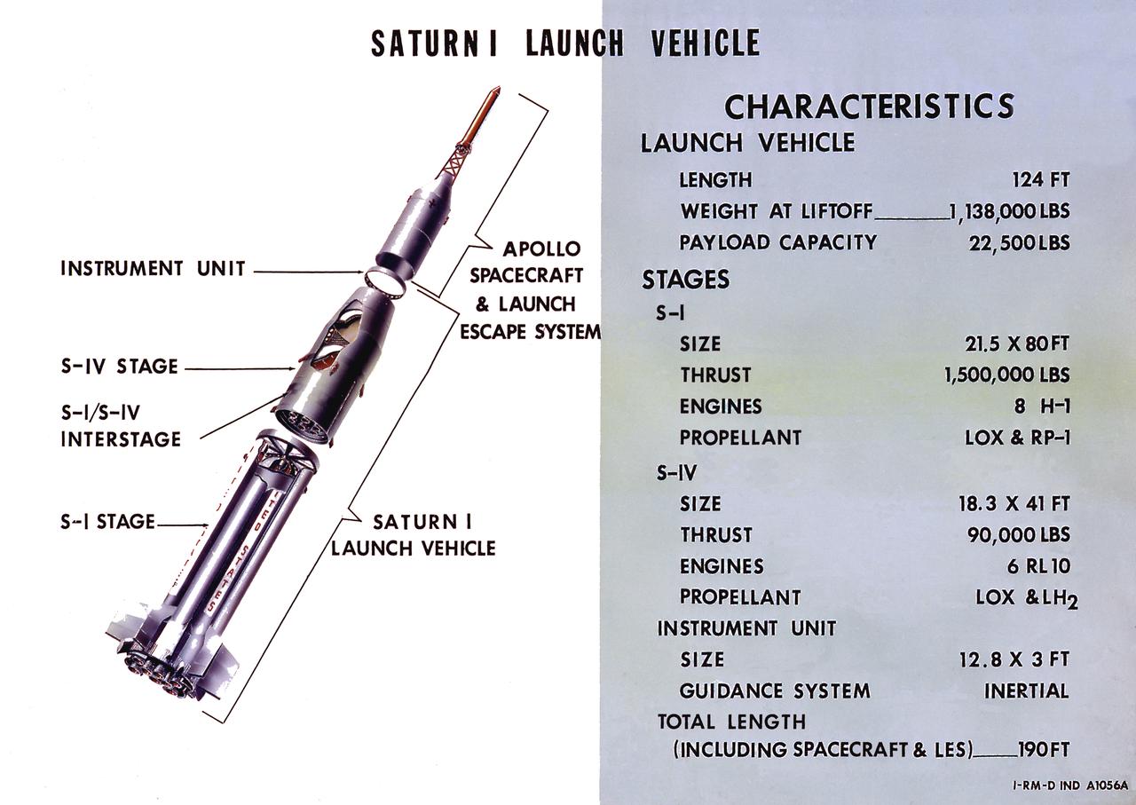
A cutaway illustration of Saturn I launch vehicle characteristics: The Saturn I, first of the Saturn launch vehicles' family, is a two-stage vehicle with a low-earth-orbit payload capability of approximately 25,000 pounds. The research and development program was plarned in two phases or blocks; one for first stage development (Block I) and the second for first and second stage development (Block II). The S-I (first) stage consisted of a cluster of nine propellant tanks and eight H-1 engines built by Rocketdyne, yeilding a total thrust of 1,500,000 pounds. The second stage identified as S-IV, was designed as a single cylinder with a common bulkhead separating the liquid oxygen from the liquid hydrogen. Propulsion was provided by six RL-10 engines built by Pratt Whitney, capable of producing a combined thrust of 90,000 pounds. Of the 10 Saturn I's planned, the first eight were designed and built at the Marshall Space Flight Center. The remaining two were built by the Chrysler Corporation.
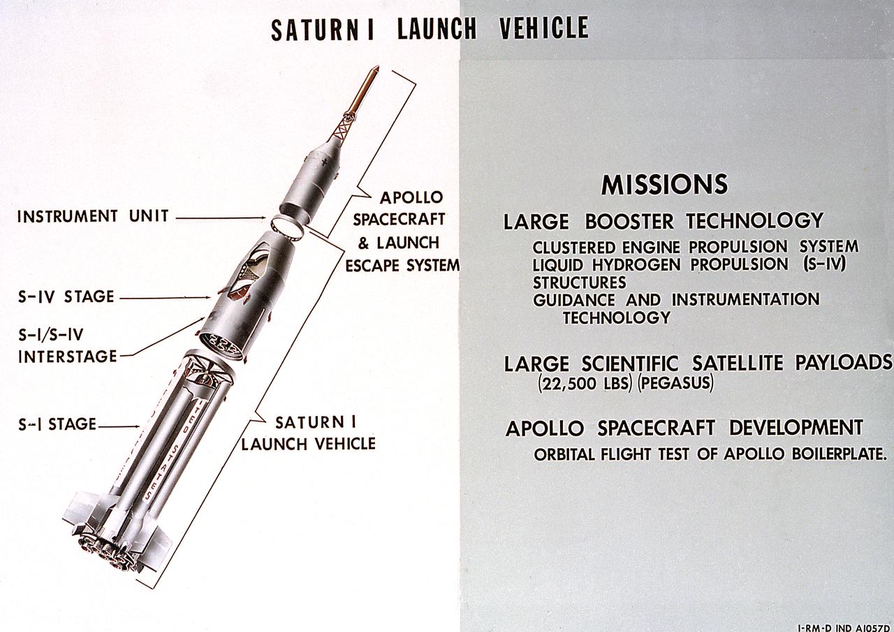
A cutaway illustration of Saturn 1 launch vehicle mission. The Saturn I, first of the Saturn launch vehicles' family, is a two-stage vehicle with a low-earth-orbit payload capability of approximately 25,000 pounds. The research and development program was plarned in two phases or blocks; one for first stage development (Block I) and the second for first and second stage development (Block II). The S-I (first) stage consisted of a cluster of nine propellant tanks and eight H-1 engines built by Rocketdyne, yeilding a total thrust of 1,500,000 pounds. The second stage of Saturn I, identified as S-IV, was designed as a single cylinder with a common bulkhead separating the liquid oxygen from the liquid hydrogen. Propulsion was provided by six RL-10 engines built by Pratt Whitney, capable of producing a combined thrust of 90,000 pounds. Of the 10 Saturn I's planned, the first eight were designed and built at the Marshall Space Flight Center. The remaining two were built by the Chrysler Corporation.
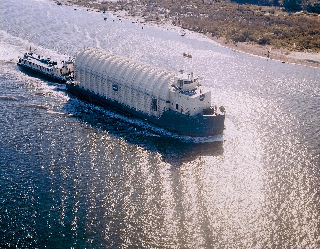
NASA used barges for transporting full-sized stages for the Saturn I, Saturn IB, and Saturn V vehicles between the Marshall Space Flight Center (MSFC), the manufacturing plant at the Michoud Assembly Facility (MAF), the Mississippi Test Facility for testing, and the Kennedy Space Center. The barges traveled from the MSFC dock to the MAF, a total of 1,086.7 miles up the Tennessee River and down the Mississippi River. The barges also transported the assembled stages of the Saturn vehicle from the MAF to the Kennedy Space Center, a total of 932.4 miles along the Gulf of Mexico and up along the Atlantic Ocean, for the final assembly and the launch. Pictured is the barge Palaemon carrying Saturn IV S-IB flight stage enroute to MSFC.