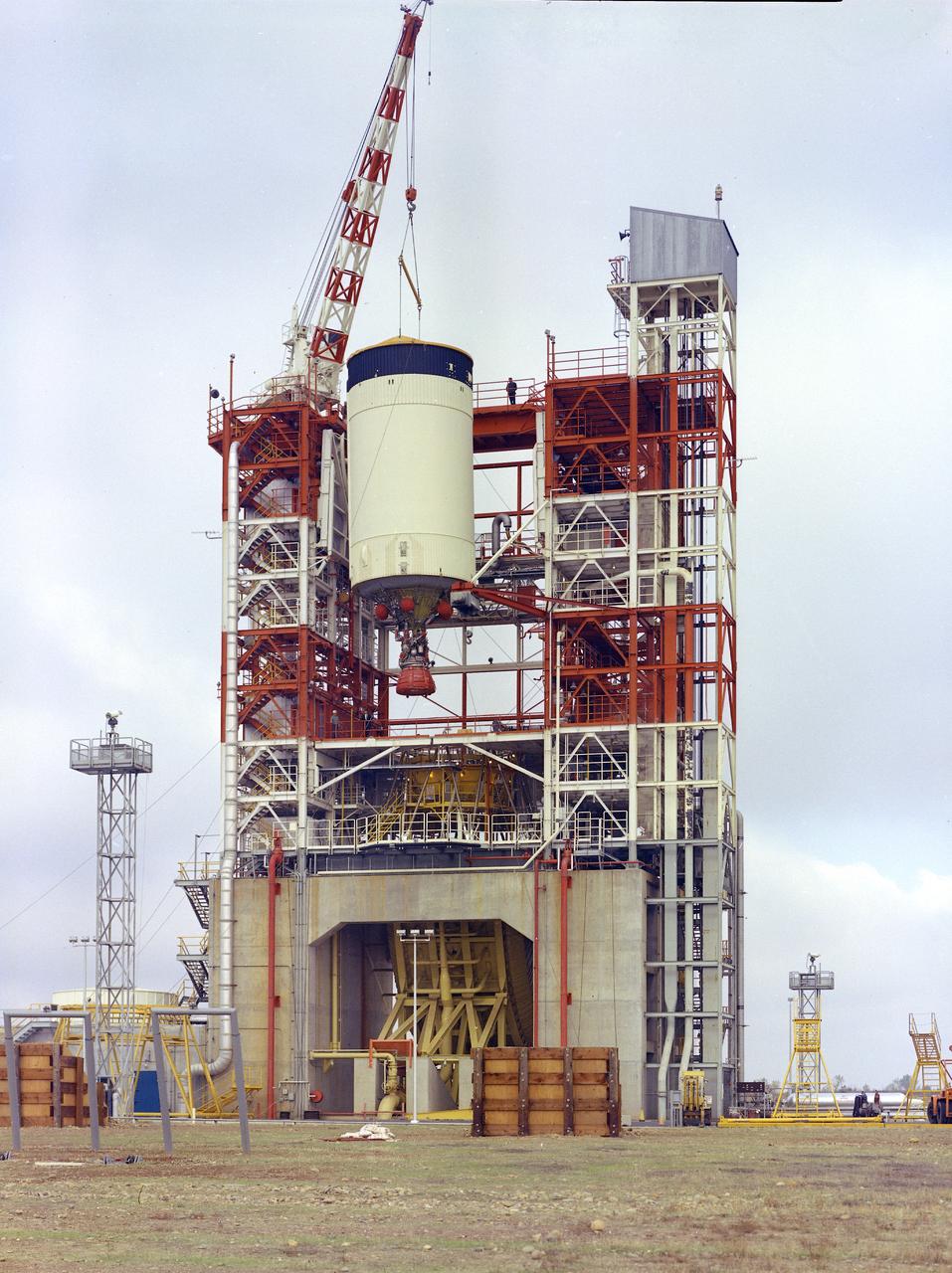
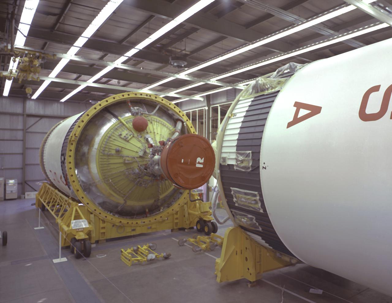
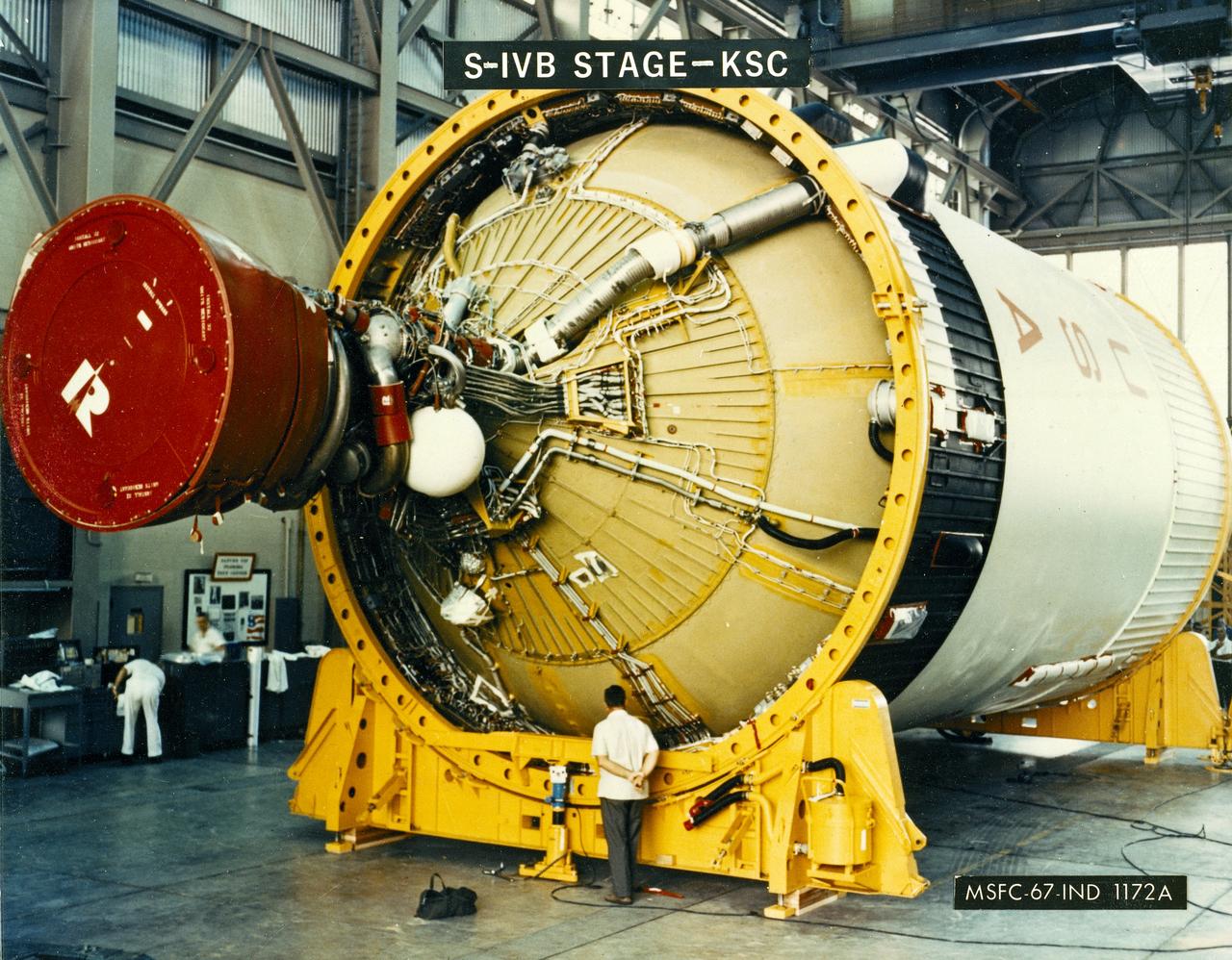
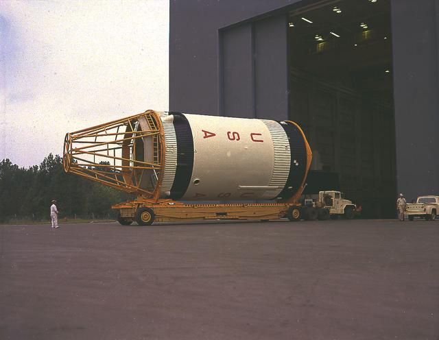
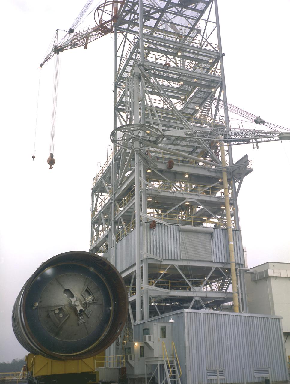
After the S-II (second) stage dropped away, the S-IVB (third) stage ignited and burned for about two minutes to place itself and the Apollo spacecraft into the desired Earth orbit. At the proper time during this Earth parking orbit, the S-IVB stage was re-ignited to speed the Apollo spacecraft to escape velocity, injecting it and the astronauts into a moon trajectory. Developed and manufactured by the Douglas Aircraft Company in Huntington, California, the S-IVB stage measures about 21.5 feet in diameter, about 58 feet in length and is powered by a single 200,000-pound-thrust J-2 engine with a re-start capability. The S-IVB stage was also used on the second stage of the Saturn IB launch vehicle. The fully-assembled S-IVB (third) stage for the AS-503 (Apollo 8 mission) launch vehicle is pictured in the Douglas' vertical checkout building.
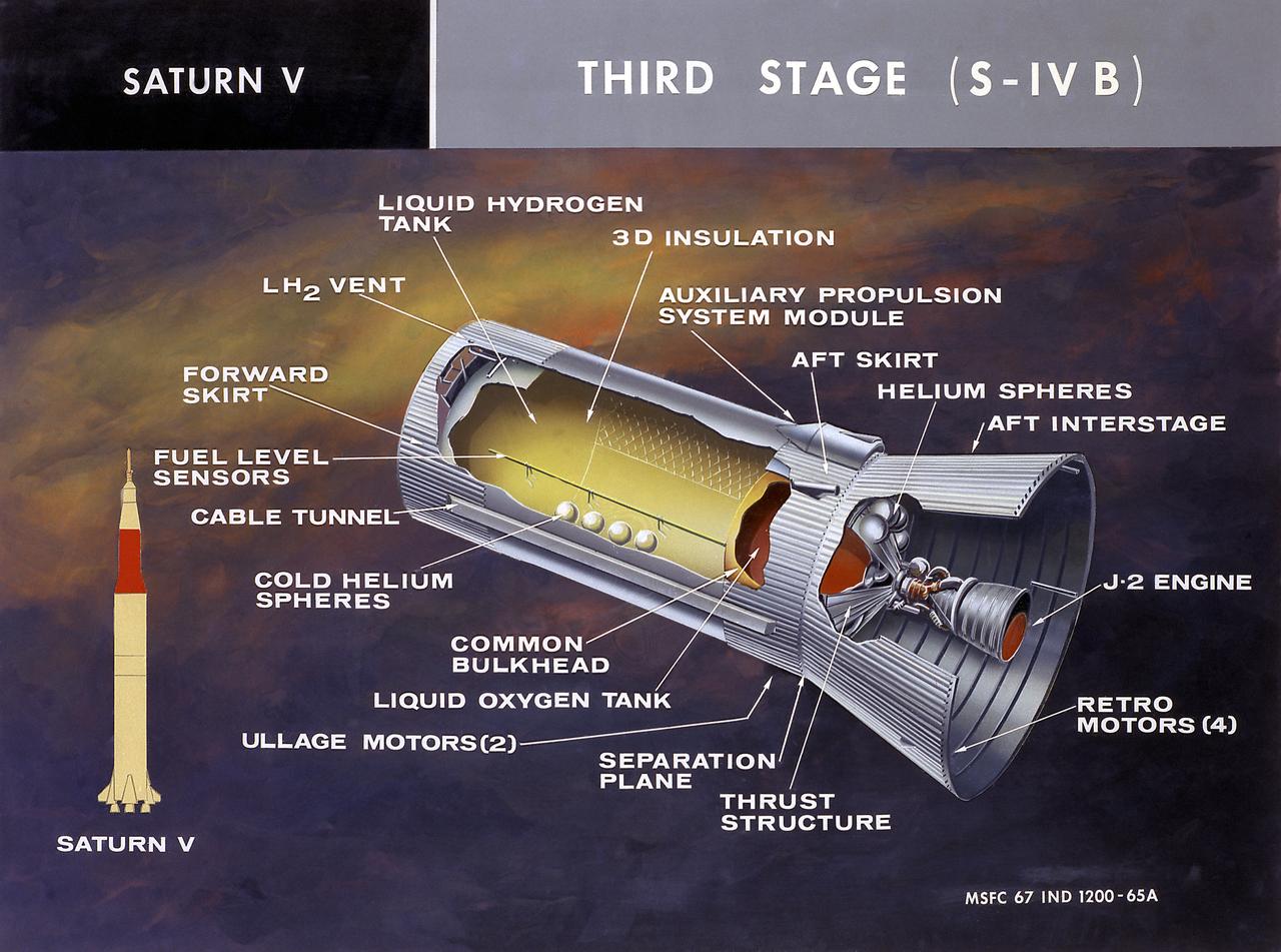
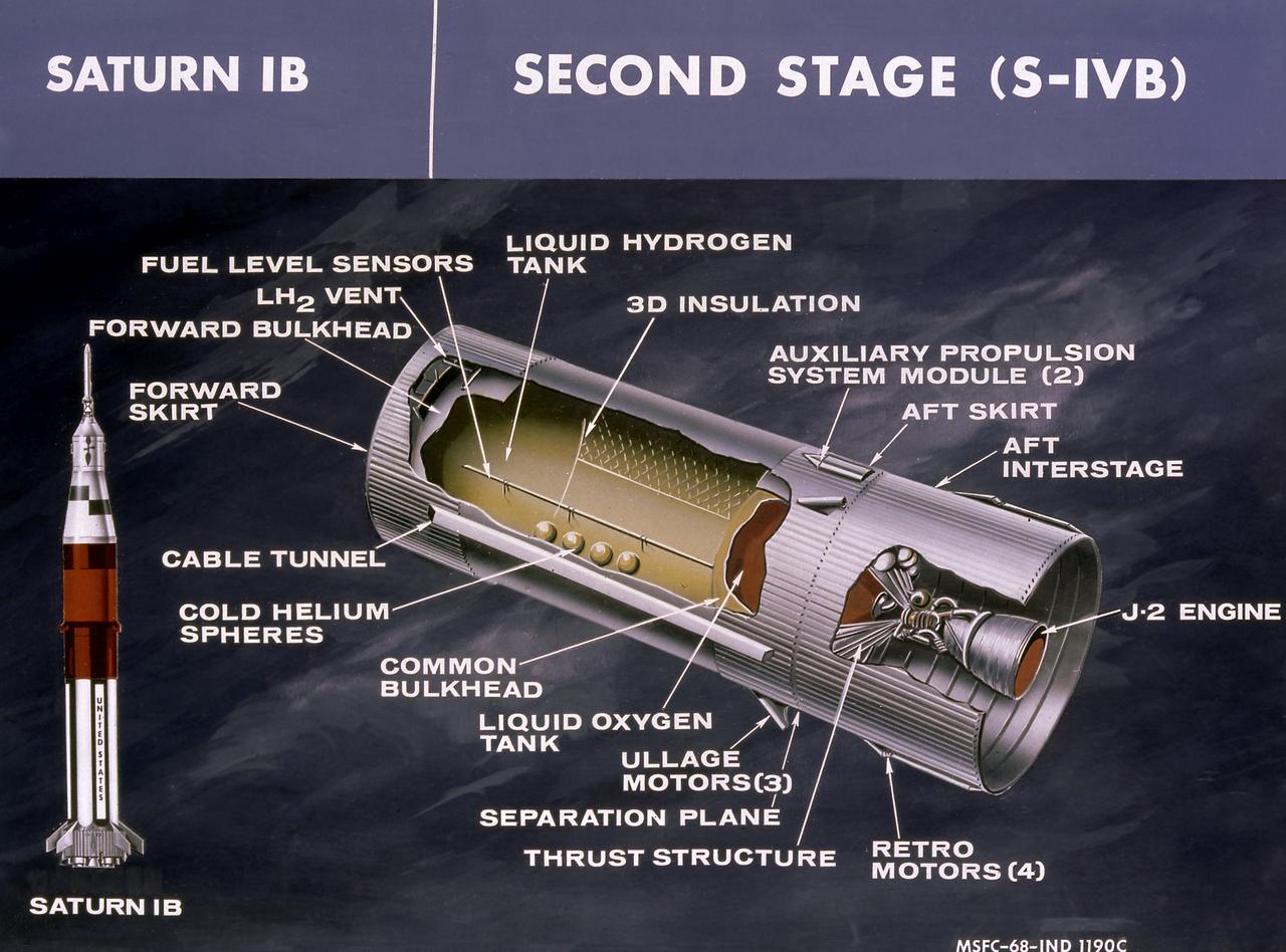
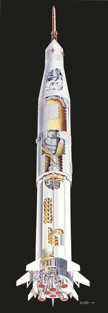
This cutaway illustration shows the Saturn V S-IVB (third) stage with the callouts of its major components. When the S-II (second) stage of the powerful Saturn V rocket burnt out and was separated the remaining units approached orbit around the Earth. Injection into the desired orbit was attaineded as the S-IVB (third stage) was ignited and burnt. The S-IVB stage was powered by a single 200,000-pound thrust J-2 engine and had a re-start capability built in for its J-2 engine. The S-IVB restarted to speed the Apollo spacecraft to escape velocity injecting it and the astronauts into a moon trajectory.
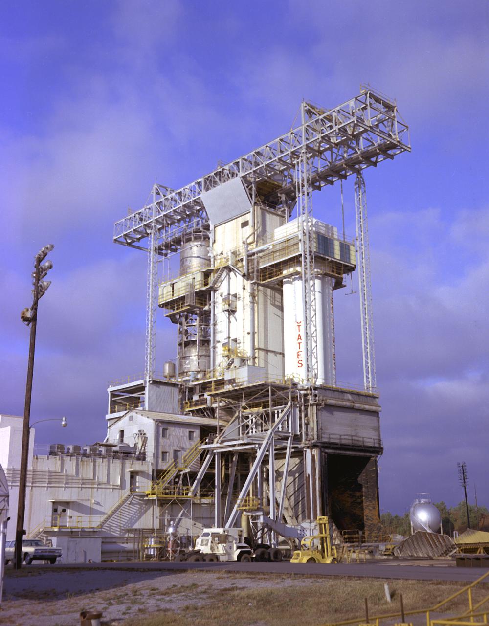
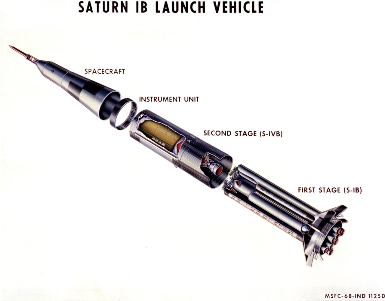
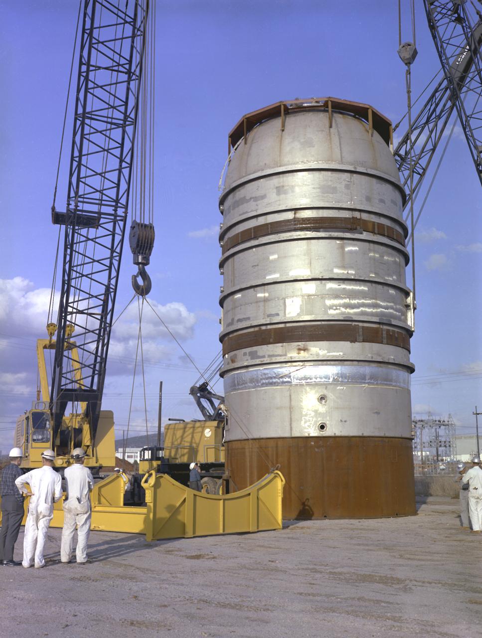
Workers at McDornel-Douglas install the Saturn IB S-IVB (second) stage for the Apollo-Soyuz mission into the company's S-IVB assembly and checkout tower in Huntington Beach, California. The Saturn IB launch vehicle was developed by the Marshall Space Flight Center (MSFC) as an interim vehicle in its "building block" approach to Saturn rocket development. This vehicle utilized the Saturn I technology to further develop and refine the capabilities of a larger booster and the Apollo spacecraft required for the manned lunar missions. The S-IVB stage, later used as the third stage of the Saturn V launch vehicle, was powered by a single J-2 engine initially capable of 200,000 pounds of thrust.
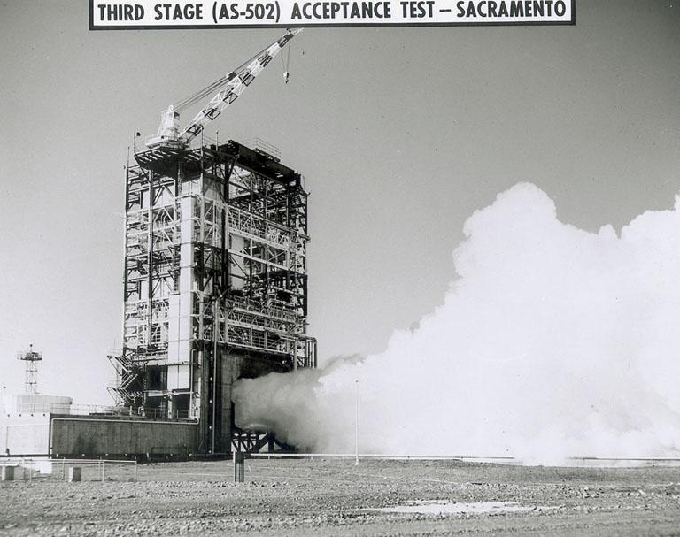
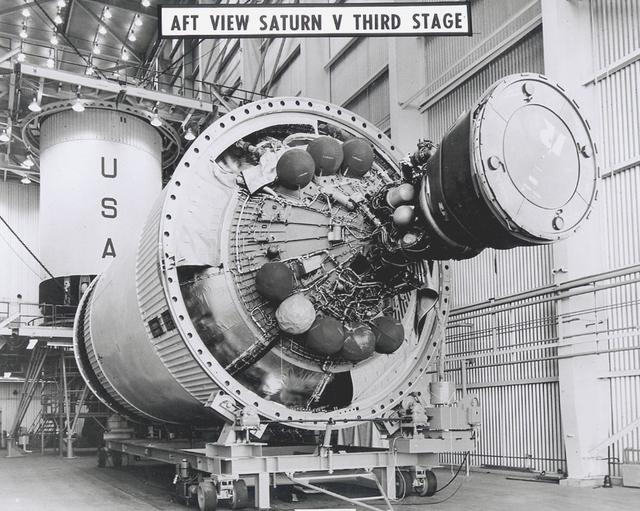
This image depicts the Saturn V S-IVB (third) stage for the Apollo 10 mission being removed from the Beta Test Stand 1 after its acceptance test at the Douglas Aircraft Company's Sacramento Test Operations (SACTO) facility. After the S-II (second) stage dropped away, the S-IVB (third) stage was ignited and burned for about two minutes to place itself and the Apollo spacecraft into the desired Earth orbit. At the proper time during this Earth parking orbit, the S-IVB stage was re-ignited to speed the Apollo spacecraft to escape velocity injecting it and the astronauts into a moon trajectory. Developed and manufactured by the Douglas Aircraft Company in California, the S-IVB stage measures about 21.5 feet in diameter, about 58 feet in length, and powered by a single 200,000-pound-thrust J-2 engine with a re-start capability. The S-IVB stage was also used on the second stage of the Saturn IB launch vehicle.
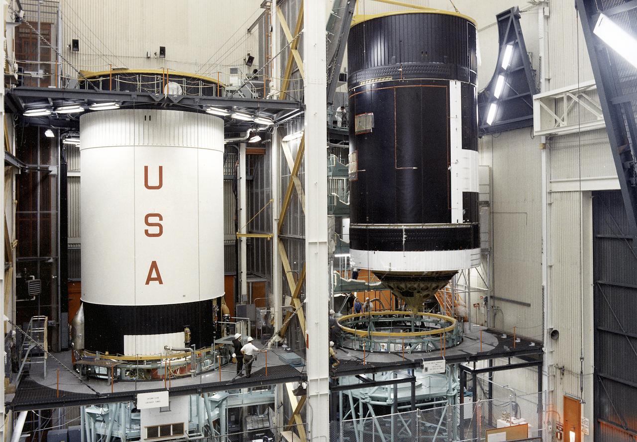
This photograph shows activities during assembly of the Skylab cluster at the Vehicle Assembly/Checkout building. The Saturn V S-IVB stage is shown at left, and right is the Orbital Workshop (OWS) being readied for mating to the thruster. The S-IVB stage was modified to house the OWS, which provided living and working quarters for the Skylab crews. The Marshall Space Flight Center had responsibilities for the design and development of the Skylab hardware, and management of experiments.
This is a view of the Saturn V S-IVB (third) stage for the AS-209 (Apollo-Soyuz test project backup vehicle) on a transporter in the right foreground, and the S-IVB stage for AS-504 (Apollo 9 mission) being installed in the Beta Test Stand 1 at the SACTO facility in California. After the S-II (second) stage dropped away, the S-IVB (third) stage ignited and burned for about two minutes to place itself and the Apollo spacecraft into the desired Earth orbit. At the proper time during this Earth parking orbit, the S-IVB stage was re-ignited to speed the Apollo spacecraft to escape velocity and inject it and the astronauts into a moon trajectory. Developed and manufactured by the Douglas Aircraft Company in California, the S-IVB stage measures about 21.5 feet in diameter, about 58 feet in length, and is powered by a single 200,000-pound-thrust J-2 engine with a re-start capability. The S-IVB stage was also used on the second stage of the Saturn IB launch vehicle.
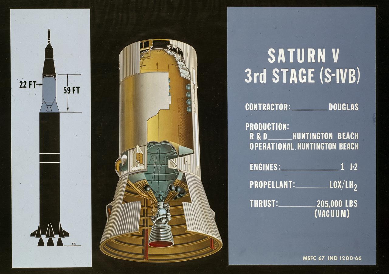
This cutaway drawing shows the S-IVB (third stage) of the Saturn V launch vehicle. As a part of the Marshall Space Flight Center’s (MSFC) “building block” approach to the Saturn development, the S-IVB stage was utilized in the Saturn IB launch vehicle as a second stage and, later, the Saturn V launch vehicle as a third stage. The 59 foot long and 22 feet diameter stage was powered by a single J-2 engine, initially capable of 200,000 pounds of thrust.
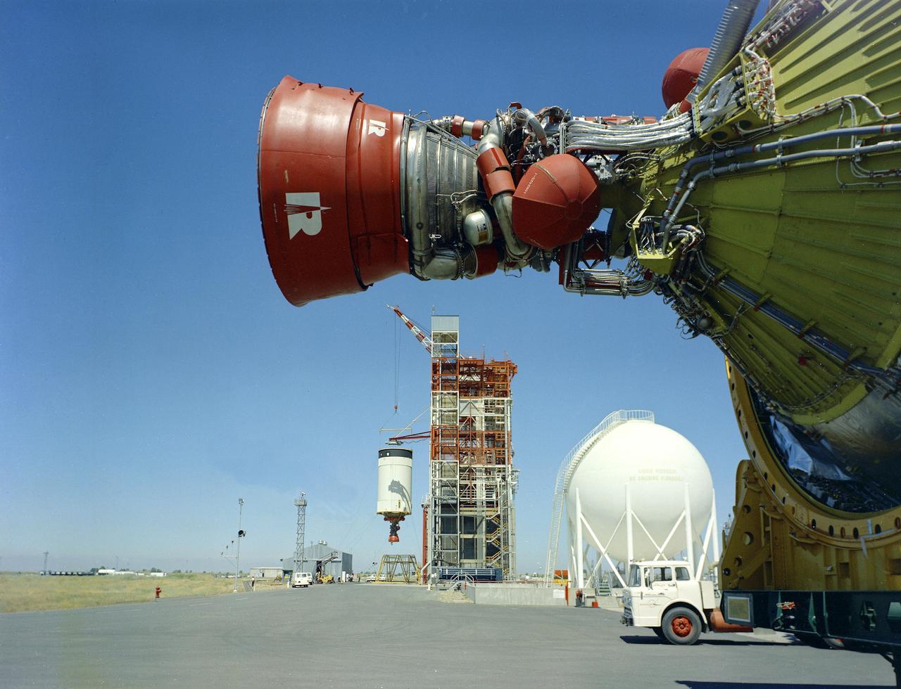
The J-2 engine for Saturn V S-IVB (third) stage blasted from the test stand at Douglas Aircraft Co., Sacramento Test Operation (SACTO) facility in California. This third stage was used on the unmarned Saturn V flight of Apollo 6 in April 1968.
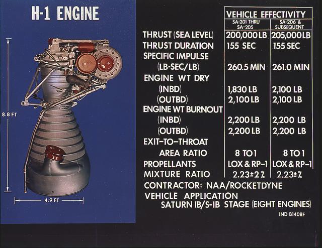
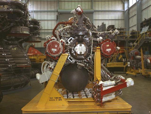
H-1 engine characteristics: The H-1 engine was developed under the management of the Marshall Space Flight Center (MSFC). The cluster of eight H-1 engines was used to power the first stage of the Saturn I (S-I stage) and Saturn IB (S-IVB stage) launch vehicles, and produced 188,00 pounds of thrust, a combined thrust of 1,500,000 pounds, later uprated to 205,000 pounds of thrust and a combined total thrust of 1,650,000 pounds for the Saturn IB program.
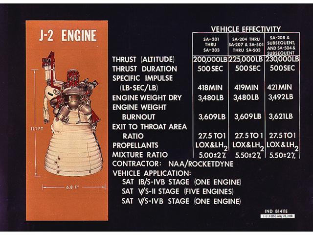
This chart is an illustration of J-2 Engine characteristics. A cluster of five J-2 engines powered the Saturn V S-II (second) stage with each engine providing a thrust of 200,000 pounds. A single J-2 engine powered the S-IVB stage, the Saturn IB second stage, and the Saturn V third stage. The engine was uprated to provide 230,000 pounds of thrust for the fourth Apollo Saturn V flight and subsequent missions. Burning liquid hydrogen as fuel and using liquid oxygen as the oxidizer, the cluster of five J-2 engines for the S-II stage burned over one ton of propellant per second, during about 6 1/2 minutes of operation, to take the vehicle to an altitude of about 108 miles and a speed of near orbital velocity, about 17,400 miles per hour.
This photograph was taken at the Redstone airfield, Huntsville, Alabama, during the unloading of the Saturn V S-IVB stage that housed the Orbital Workshop (OWS) from the Super Guppy, the NASA plane that was specially built to carry oversized cargo. The OWS measured 22 feet (6.7 m) in diameter, and 48 feet (14.6 m) in length. The Saturn V S-IVB stage was modified at the McDornell Douglas facility at Huntington Beach, California, for a new role, which was to house the OWS. In addition to the test articles, engineering mockups, and flight equipment, both McDonnell Douglas and Martin Marietta built 0-G trainers, neutral buoyancy trainers, and high-fidelity mockups for the 1-G trainer to be used in the KC-135 aircraft. The Marshall Space Flight Center had program management responsibility for the development of Skylab hardware and experiments.
SL3-114-1625 (July-September 1973) --- An excellent view of the expended S-IVB second stage of the Skylab 3/Saturn 1B space vehicle is seen in this photograph taken from the Skylab 3 Command and Service Module (CSM) in Earth orbit. The land mass below is Italy and France, with part of the Mediterranean Sea visible. This photograph was taken with a handheld 70mm Hasselblad camera using a 100mm lens, and medium speed Ektachrome film. Photo credit: NASA
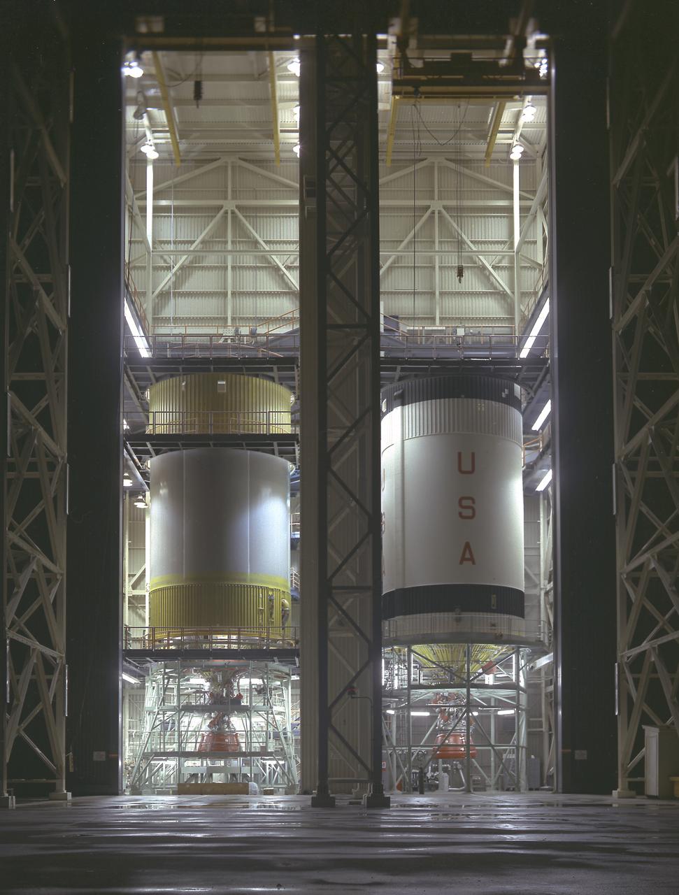
S-IVB-505 and S-IVB-211, the flight version of the S-IVB stages, in the McDornell Douglas' S-IVB Assembly and Checkout Tower in Huntington Beach, California. As a part of the Marshall Space Flight Center `s "building block" approach to the Saturn vehicle development, the S-IVB stage, in its 200 series, was utilized as the Saturn IB launch vehicle's second stage, and, in its 500 series, the Saturn V's third stage. The S-IVB was powered by a single J-2 engine, initially capable of 200,000 pounds of thrust.
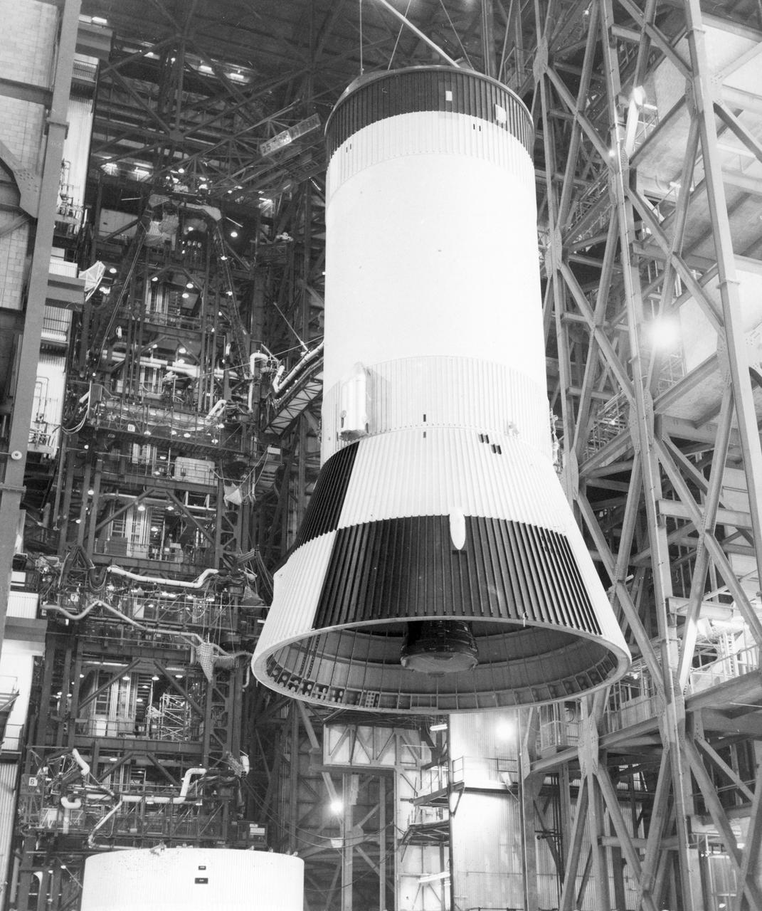
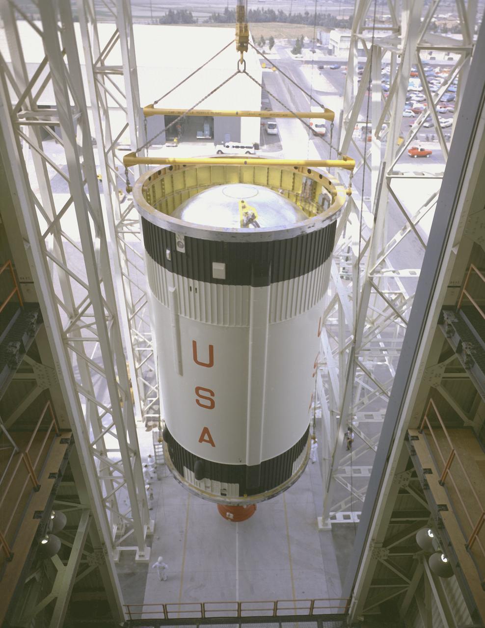
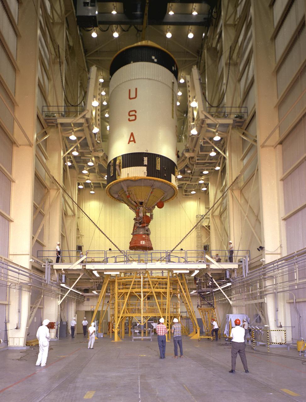
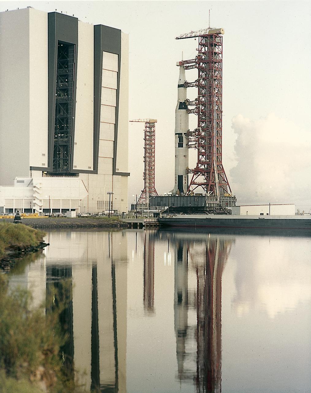
The third stage (S-IVB) of the Saturn V launch vehicle for the Apollo 11 lunar landing mission is hoisted in the vehicle assembly building at the NASA Kennedy Space Center (KSC) for mating with the second stage (S-II). The vehicle, designated as AS-506, projected the first lunar landing mission, Apollo 11, on a trajectory for the Moon. The Apollo 11 mission launched from KSC in Florida via the Marshall Space Flight Center (MSFC) developed Saturn V launch vehicle on July 16, 1969 and safely returned to Earth on July 24, 1969. Astronauts onboard included Neil A. Armstrong, commander; Michael Collins, Command Module (CM) pilot; and Edwin E. Aldrin, Jr., Lunar Module (LM) pilot. The CM, “Columbia”, piloted by Collins, remained in a parking orbit around the Moon while the LM, “Eagle’’, carrying astronauts Armstrong and Aldrin, landed on the Moon. On July 20, 1969, Armstrong was the first human to ever stand on the lunar surface, followed by Aldrin. During 2½ hours of surface exploration, the crew collected 47 pounds of lunar surface material for analysis back on Earth. With the success of Apollo 11, the national objective to land men on the Moon and return them safely to Earth had been accomplished.
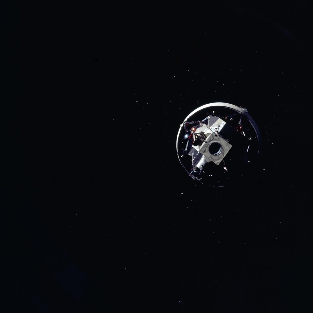
AS12-50-7328 (14 Nov. 1969) --- Apollo 12 Lunar Module (LM), still attached to the Saturn V third (S-IVB) stage, is pictured as seen from Apollo 12 Command and Service Modules (CSM) on the first day of the Apollo 12 lunar landing mission. This photograph was taken following CSM separation from LM/S-IVB and prior to Lunar Module extraction from the S-IVB stage. The Spacecraft Lunar Module Adapter (SLA) panels have already been jettisoned.
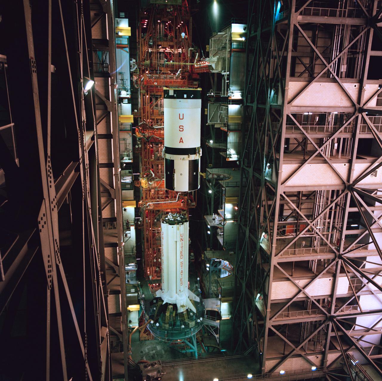
S75-20909 (January 1975) --- A high-angle view of the high-bay area in the Vehicle Assembly Building at the Kennedy Space Center showing the second (S-IVB) stage of the Saturn 1-B launch vehicle for the joint U.S.-USSR Apollo-Soyuz Test Project mission being hoisted into position for mating atop the first (S-1B) stage. The major components of the American ASTP space vehicle will be the S-1B stage, the S-IVB stage, and a payload consisting of a Command/Service Module and a Docking Module.
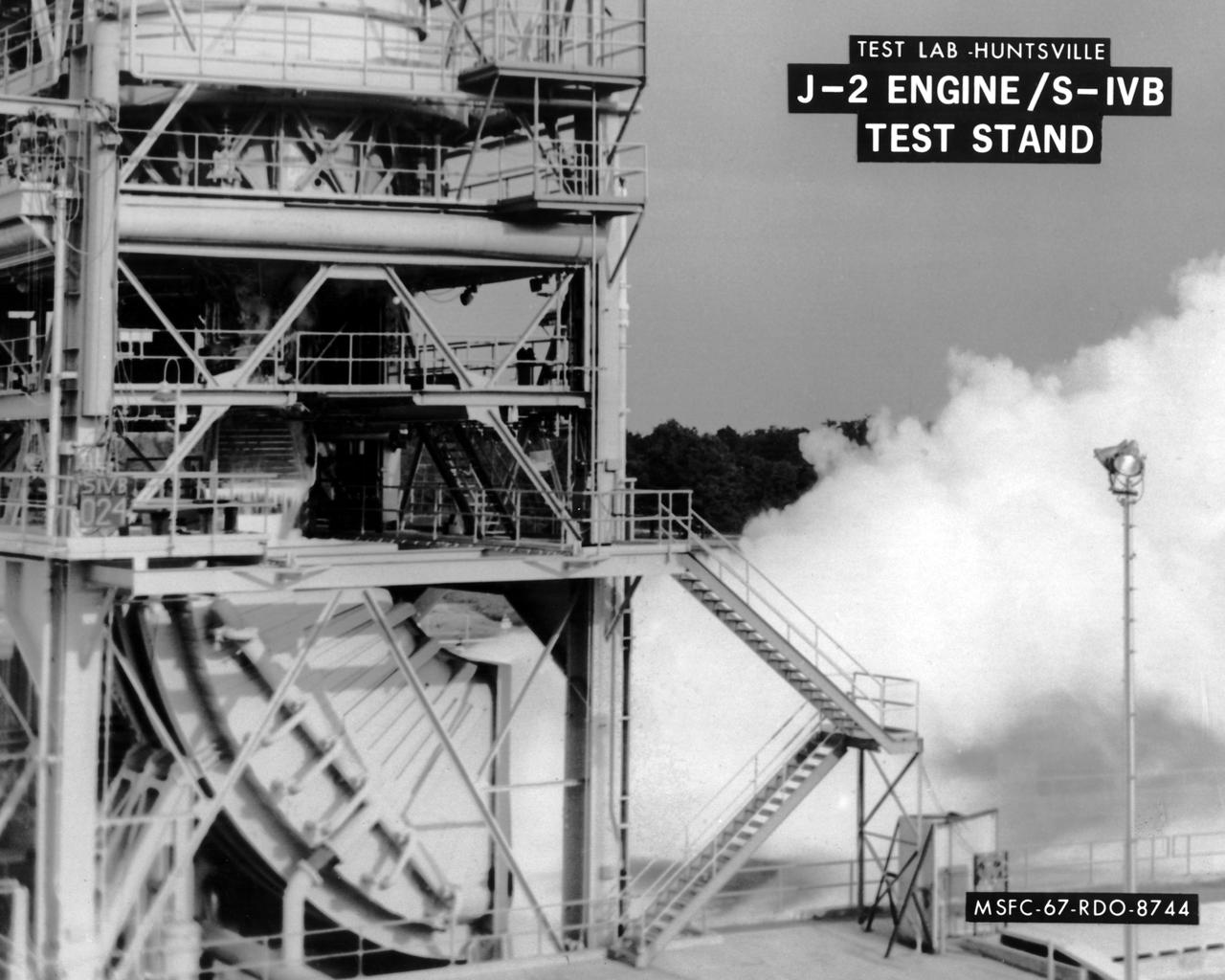
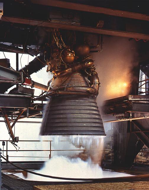
This image depicts the test firing of a J-2 engine in the S-IVB Test Stand at the Marshall Space Flight Center (MSFC). The J-2, developed by Rocketdyne under the direction of MSFC, was propelled by liquid hydrogen and liquid oxygen. A single J-2 was utilized in the S-IVB stage (the second stage for the Saturn IB and third stage for the Saturn V) and in a cluster of five for the second stage (S-II) of the Saturn V. Initially rated at 200,000 pounds of thrust, the engine was later upgraded in the Saturn V program to 230,000 pounds.
This cutaway drawing shows the S-IVB stage in its Saturn IB configuration. As a part of the Marshall Space Flight Center's (MSFC) "building block" approach to the Saturn development, the S-IVB stage was utilized in the Saturn IB launch vehicle as a second stage and, later, the Saturn V launch vehicle as a third stage. The stage was powered by a single J-2 engine, initially capable of 200,000 pounds of thrust.
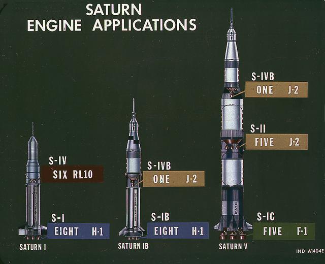
This image illustrates the basic differences between the three Saturn launch vehicles developed by the Marshall Space Flight Center. The Saturn I, consisted of two stages, the S-I (eight H-1 engines) and the S-IV (six RL-10 engines). The Saturn IB (center) also consisted of two stages, the S-IB (eight H-1 engines) and the S-IVB (one J-2 engine). The Saturn V consisted of three stages, the S-IC (five F-1 engines), the S-II (five J-2 engines), and the S-IVB (one J-2 engine).
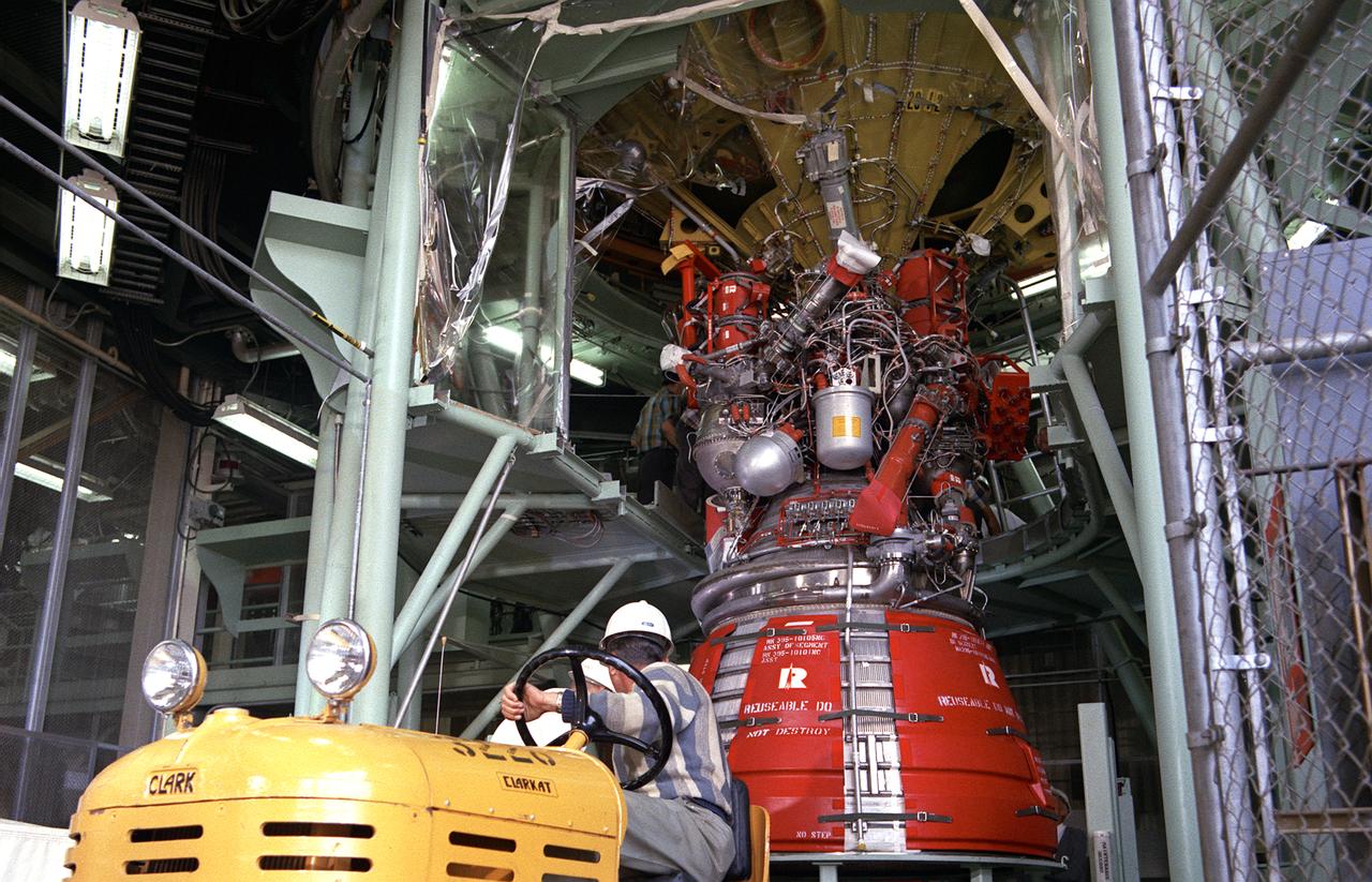
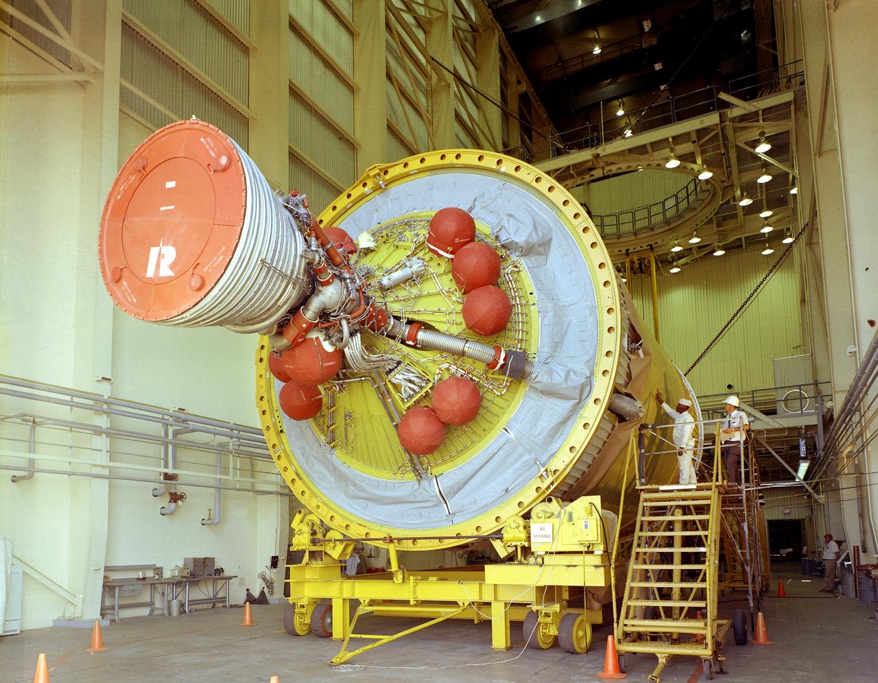
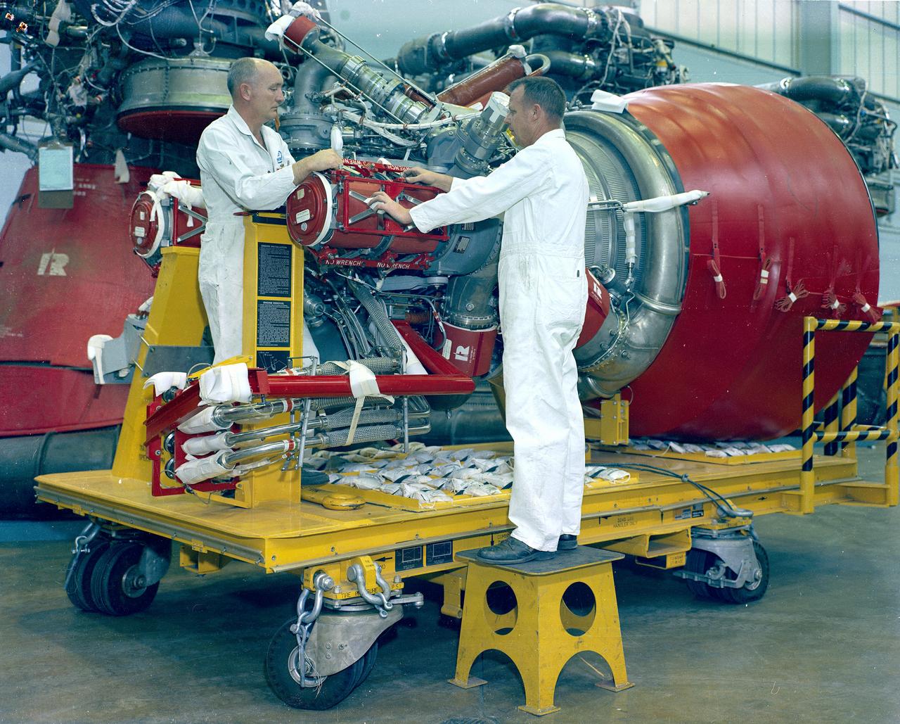
Workmen secure a J-2 engine onto the S-IVB (second) stage thrust structure. As part of Marshall Space Center's "building block" approach to the Saturn development, the S-IVB was utilized in the Saturn IBC launch vehicle as a second stage and the Saturn V launch vehicle as a third stage. The booster, built for NASA by McDornell Douglas Corporation, was powered by a single J-2 engine, initially capable of 200,000 pounds of thrust.
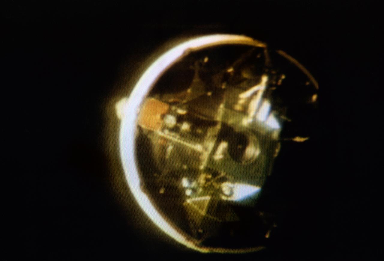
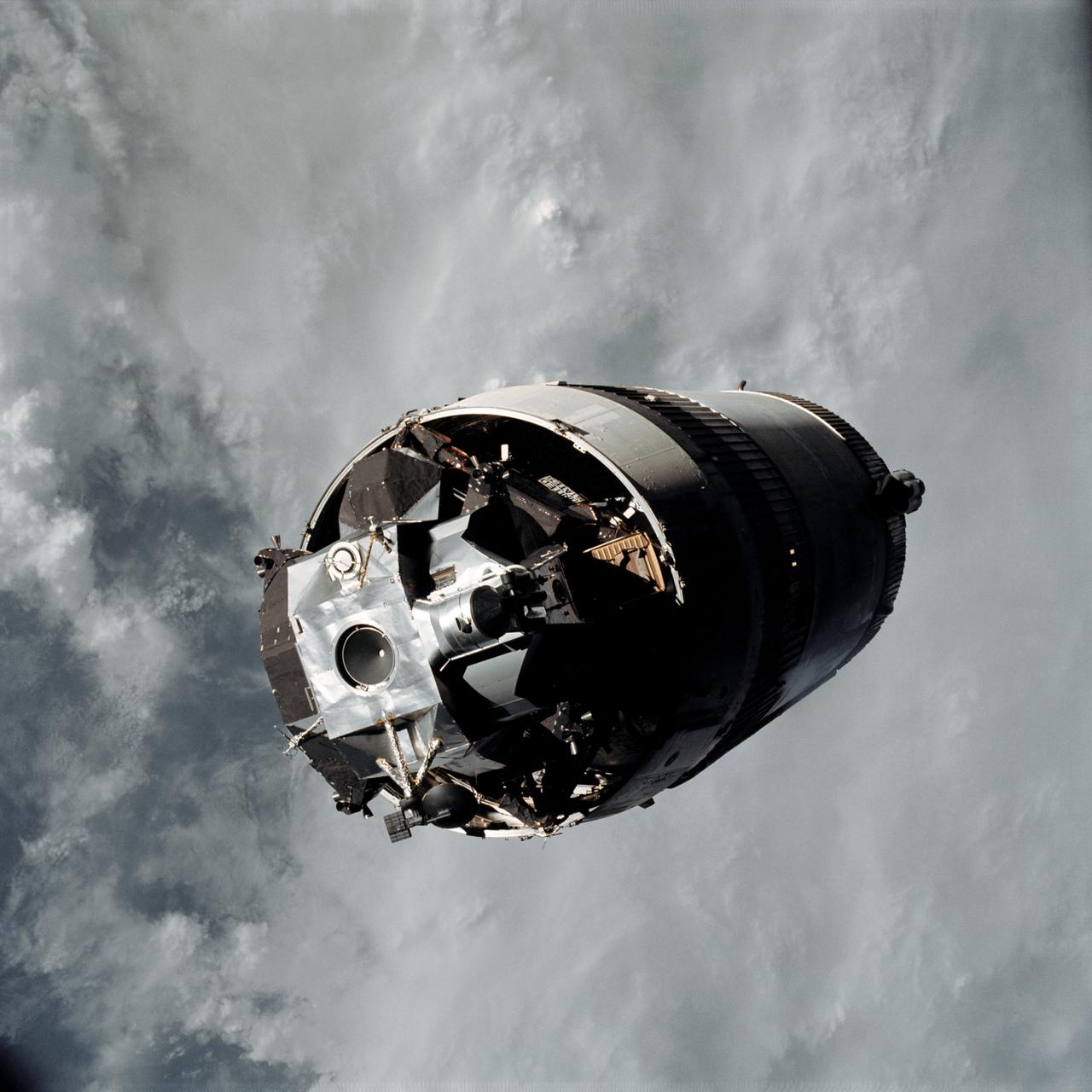
S69-33994 (18 May 1969) --- The Apollo 10 Lunar Module, still attached to the Saturn IVB stage, is seen in this color reproduction taken from the first television transmission made by the color television camera aboard the Apollo 10 spacecraft. This picture was made following CSM/LM-S-IVB separation, and prior to LM extraction from the S-IVB. The Command and Service Modules were making the docking approach to the LM/S-IVB. The circular object is the docking drogue assembly on the LM. Aboard the Command Module were astronauts Thomas P. Stafford, commander; John W. Young, command module pilot; and Eugene A. Cernan, lunar module pilot.
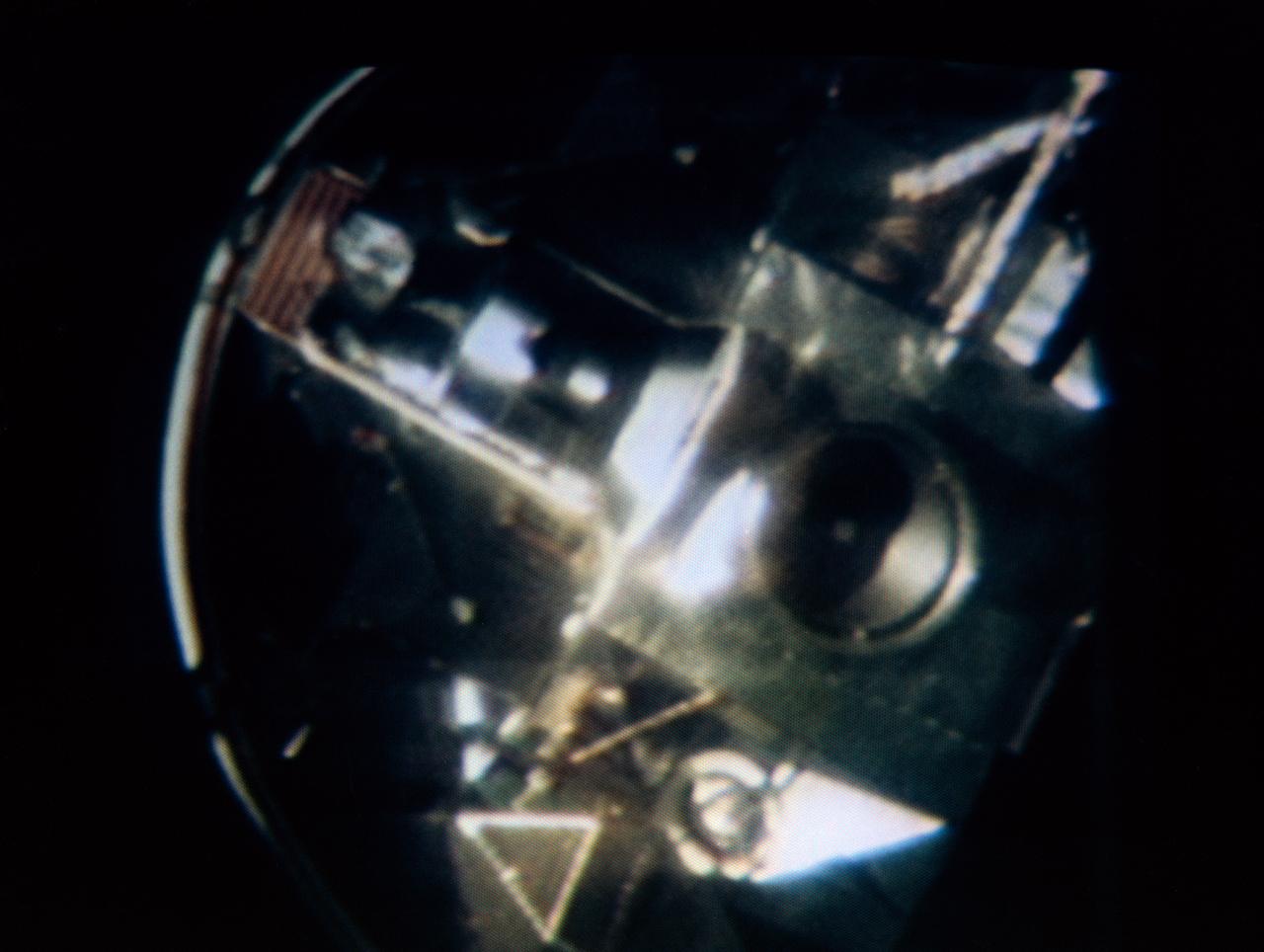
S69-33993 (18 May 1969) --- The Apollo 10 Lunar Module, still attached to the Saturn IVB stage, is seen in this color reproduction taken from the first television transmission made by the color television camera aboard the Apollo 10 spacecraft. This picture was made following CSM/LM-S-IVB separation, and prior to LM extraction from the S-IVB. The Command and Service Modules were making the docking approach to the LM/S-IVB. The circular object is the docking drogue assembly on the LM. Aboard the Command Module were astronauts Thomas P. Stafford, commander; John W. Young, command module pilot; and Eugene A. Cernan, lunar module pilot.
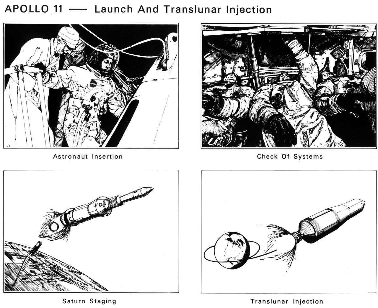
The astronauts enter the spacecraft. After launch and Saturn V first-stage burnout and jettison, the S-II second stage ignites. The crew checks spacecraft systems in Earth orbit before the S-IVB third stage ignites the second time to send Apollo 11 to the Moon
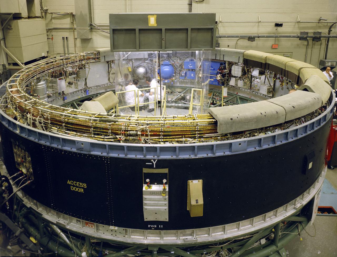
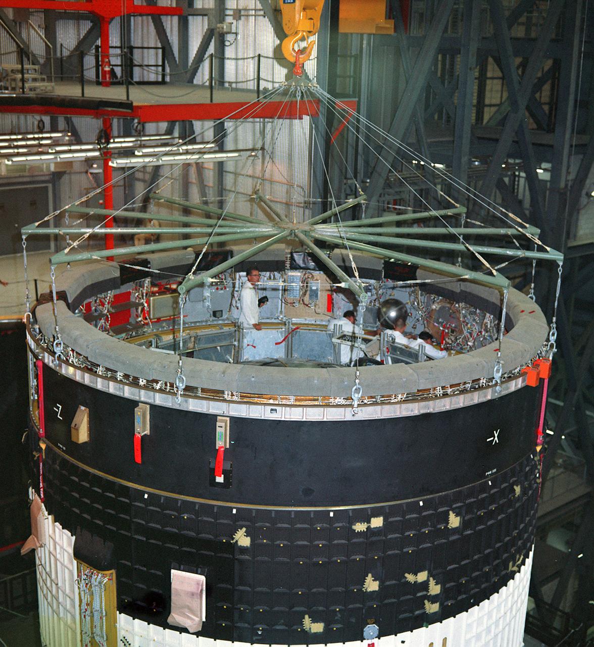
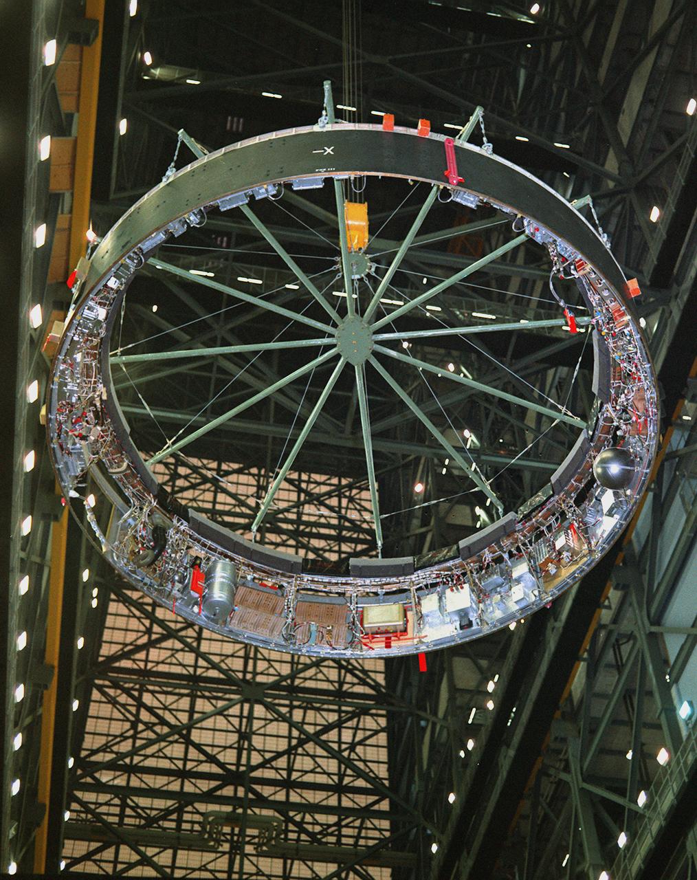
This view depicts engineers conducting a system test on the Saturn V instrument unit (IU) at International Business Machines (IBM) in Huntsville, Alabama. IBM is a prime contractor for development and fabrication of the IU. The IU is vital to the proper flight of the vehicle. It contains navigation, guidance, control, and sequencing equipment for the launch vehicle. Three-feet tall, twenty-one feet in diameter, and weighing about 4,000 pounds, the IU is mounted atop the S-IVB (third) stage, between the S-IVB stage and the Apollo spacecraft.
The Saturn IB S-IVB (second) stages in storage at the Douglas Aircraft Company's Sacramento Test Operations Facility (SACTO) in Sacramento, California. Designed and developed by the Marshall Space Flight Center and the Douglas Aircraft Company, the S-IVB stage was powered by a single J-2 engine, which produced 200,000 pounds of thrust, later uprated to 230,000 pounds for the Saturn V launch vehicle.
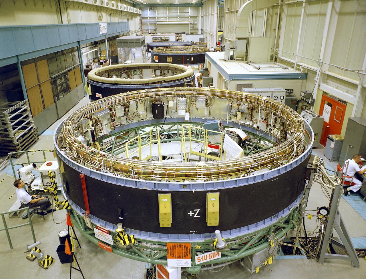
This is a view of the Saturn V instrument unit (IU) being manufactured in the east high bay at International Business Machines (IBM) in Huntsville, Alabama. IBM is a prime contractor for development and fabrication of the IU. The IU is vital to the proper flight of the vehicle. It contains navigation, guidance, control, and sequencing equipment for the launch vehicle. Three feet tall, twenty-one feet in diameter, and weighing about 4,000 pounds, the IU is mounted atop the S-IVB (third) stage, between the S-IVB stage and the Apollo spacecraft.
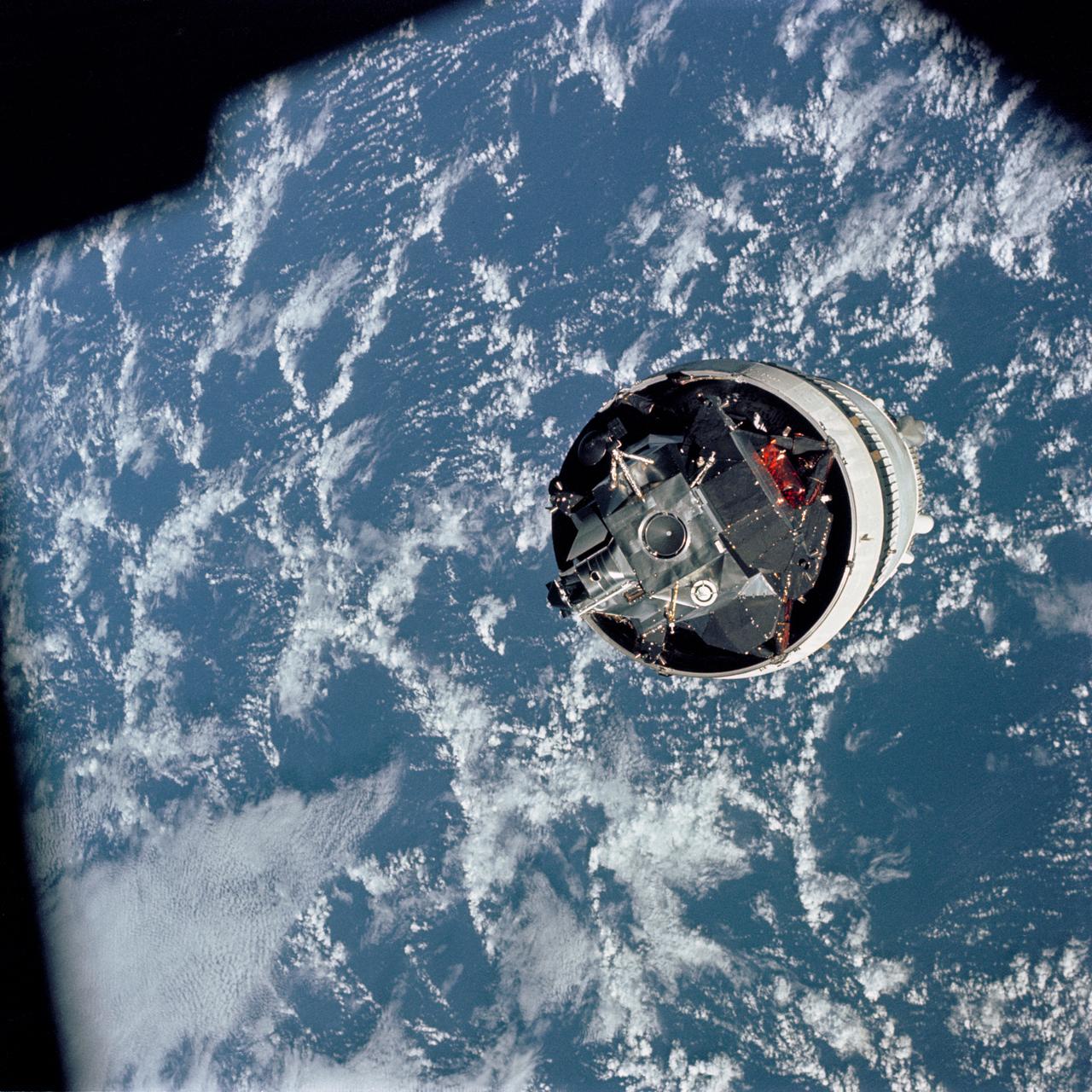
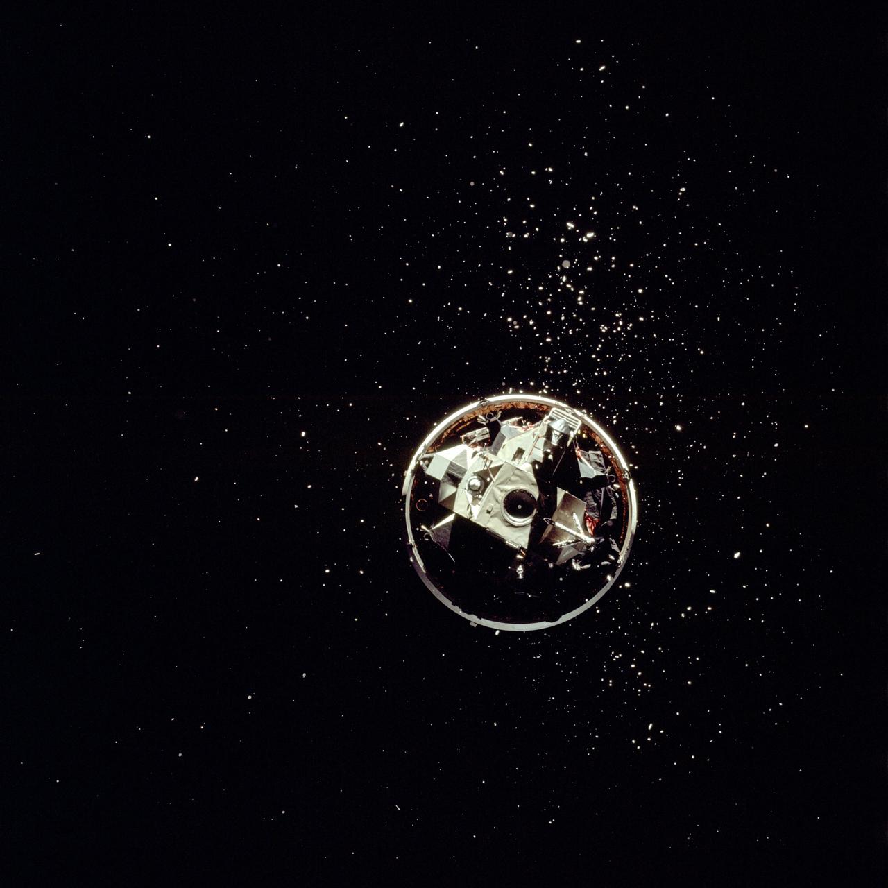
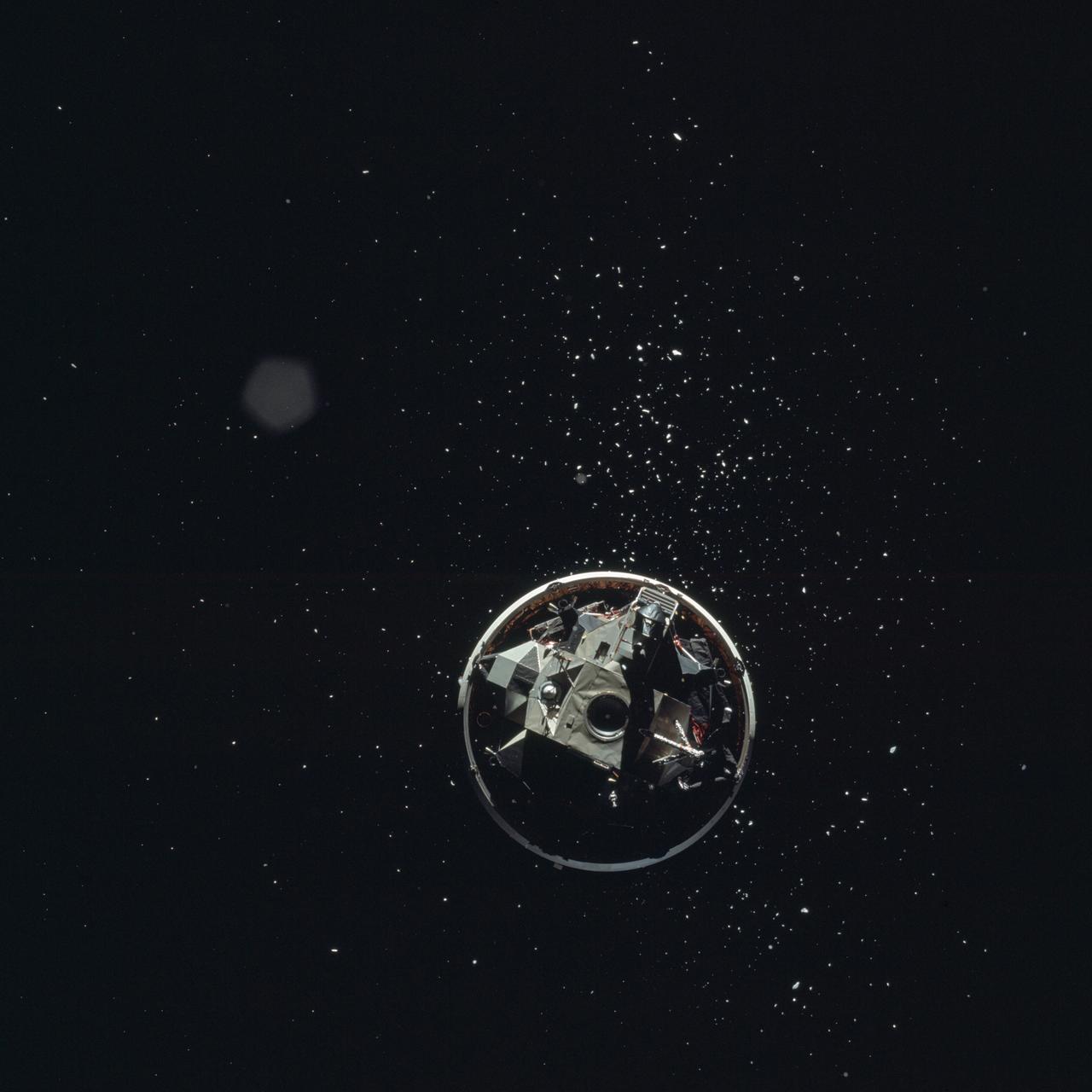
The Lunar Module (LM) 3 "Spider",still attached to the Saturn V third (S-IVB) stage,is photographed from the Command/Service Module (CSM) "Gumdrop" on the first day of the Apollo 9 Earth-orbital mission. This picture was taken following CSM/LM-S-IVB separation,and prior to LM extraction from the S-IVB. The Spacecraft Lunar Module Adapter (SLA) panels have already been jettisoned. Film magazine was A,film type was SO-368 Ektachrome with 0.460 - 0.710 micrometers film / filter transmittance response and haze filter, 80mm lens.
AS09-19-2919 (3 March 1969) --- The Lunar Module (LM) "Spider", still attached to the Saturn V third (S-IVB) stage, is photographed from the Command and Service Modules (CSM) "Gumdrop" on the first day of the Apollo 9 Earth-orbital mission. This picture was taken following CSM/LM-S-IVB separation and prior to LM extraction from the S-IVB. The Spacecraft Lunar Module Adapter (SLA) panels have already been jettisoned. Inside the Command Module were astronauts James A. McDivitt, commander; David R. Scott, command module pilot; and Russell L. Schweickart, lunar module pilot.
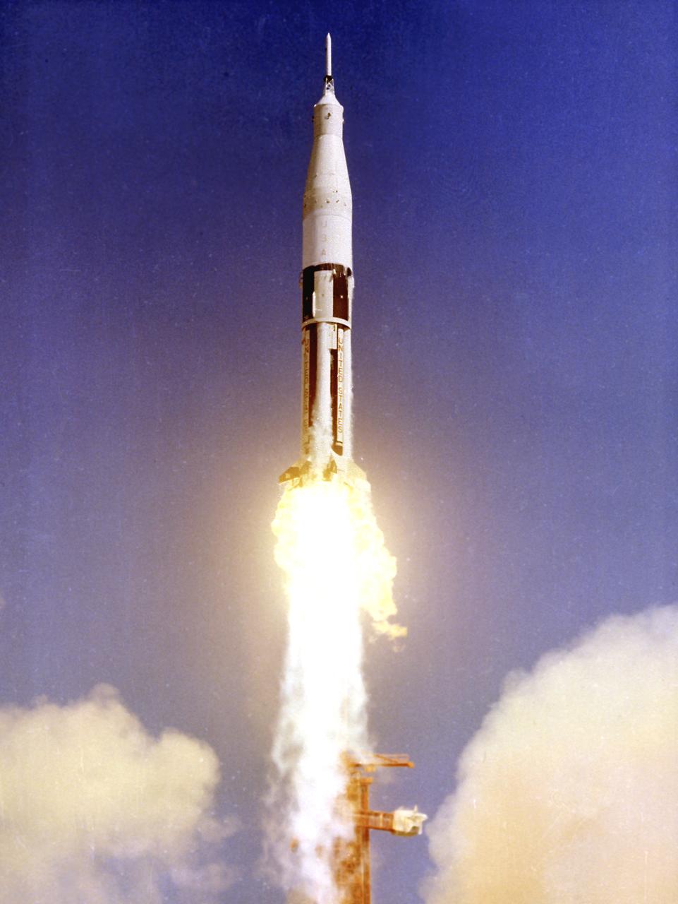
AS-201, the first Saturn IB launch vehicle developed by the Marshall Space Flight Center (MSFC), lifts off from Cape Canaveral, Florida, February 26, 1966. This was the first flight of the S-IB and S-IVB stages, including the first flight test of the liquid-hydrogen/liquid oxygen-propelled J-2 engine in the S-IVB stage. During the thirty-seven minute flight, the vehicle reached an altitude of 303 miles and traveled 5,264 miles downrange. In all, nine Saturn IB flights were made, ending with the Apollo Soyuz Test Project (ASTP) in July 1975.
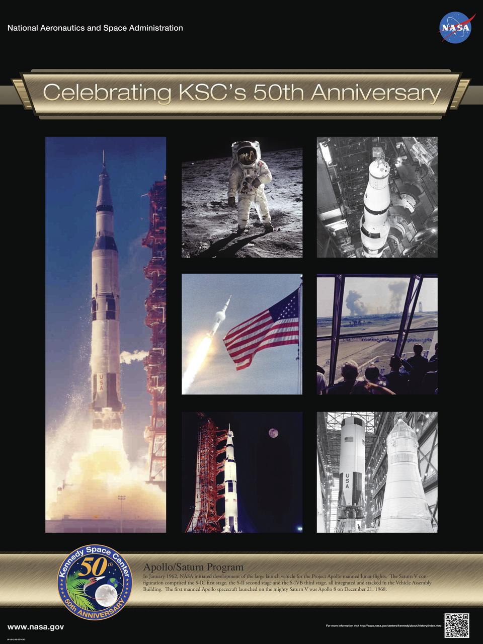
Apollo/Saturn Program: In January 1962, NASA initiated development of the large launch vehicle for the Project Apollo manned lunar flights. The Saturn V configuration comprised the S-IC first stage, the S-II second stage and the S-IVB third stage, all integrated and stacked in the Vehicle Assembly Building. The first manned Apollo spacecraft launched on the mighty Saturn V was Apollo 8 on December 21, 1968. Poster designed by Kennedy Space Center Graphics Department/Greg Lee. Credit: NASA
SL3-114-1634 (July-September 1973) --- Skylab 3, Saturn S-4B (S-IVB) stage falls away from the Command Module (CM) after separation. Earth limb in background, pass over Israel, the Dead Sea and the Mediterranean Sea. Photo credit: NASA
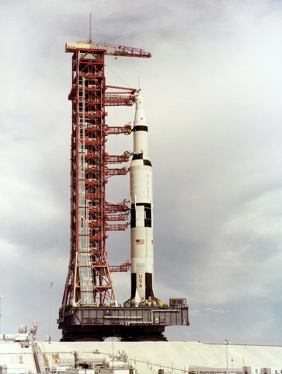
A NASA technician is dwarfed by the gigantic Third Stage (S-IVB) as it rests on supports in a facility at KSC. The towering 363-foot Saturn V was a multi-stage, multi-engine launch vehicle standing taller than the Statue of Liberty. Altogether, the Saturn V engines produced as much power as 85 Hoover Dams.
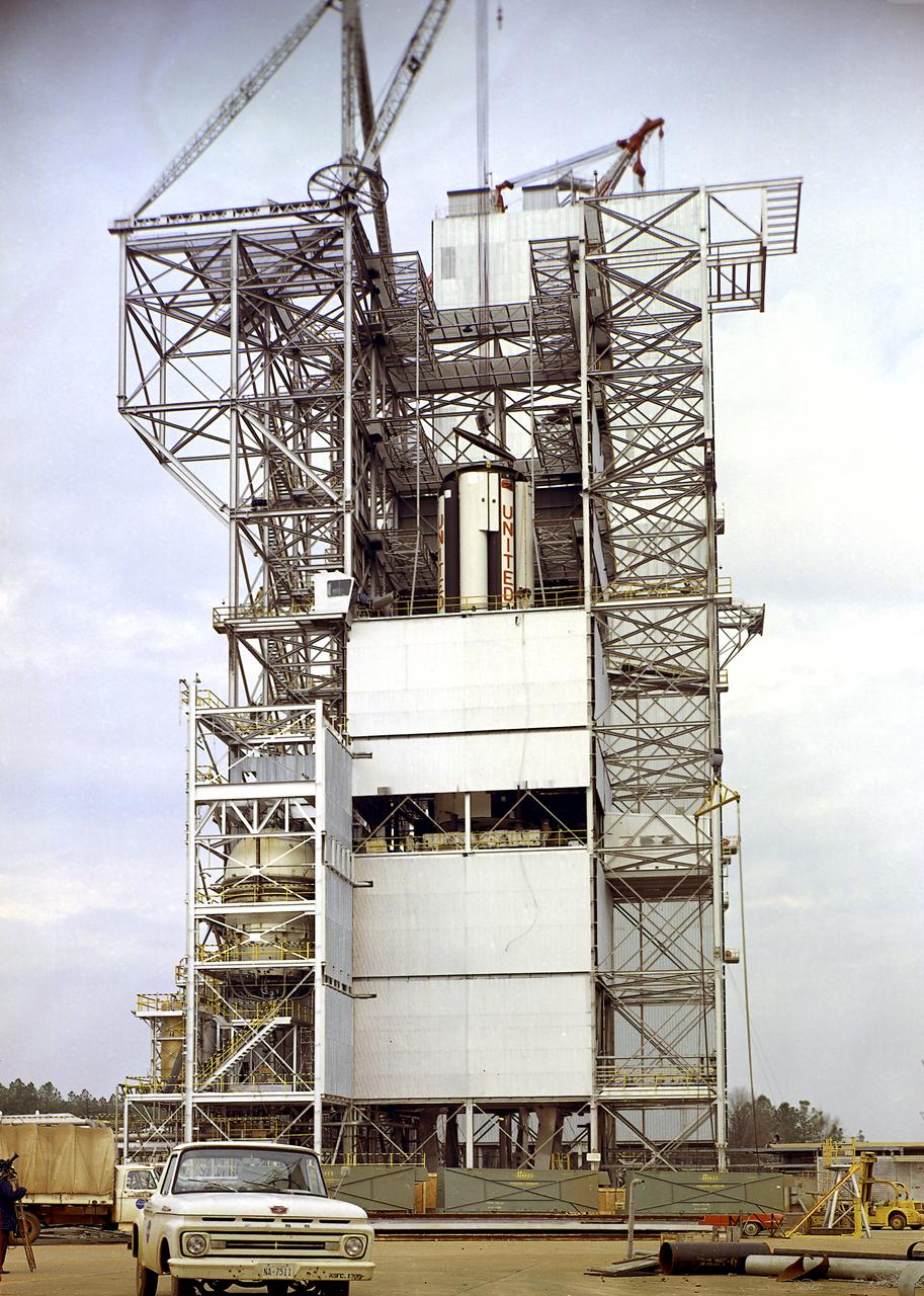
S-IB-211, the flight version of the Saturn IB launch vehicle's (S-IVB) first stage, after installation at the Marshall Space Flight Center's (MSFC's) S-IB static test stand. Between December 1967 and April 1968, the stage would undergo seven static test firings. The S-IB, developed by the MSFC and built by the Chrysler Corporation at the Michoud Assembly Facility near New Orleans, Louisiana, utilized eight H-1 engines and each produced 200,000 pounds of thrust.
S-IB-211, the flight version of the Saturn IB launch vehicle's first (S-IVB) stage, arrives at Marshall Space Flight Center's (MSFC's) S-IB static test stand. Between December 1967 and April 1968, the stage would undergo seven static test firings. The S-IB, developed by the MSFC and built by the Chrysler Corporation at the Michoud Assembly Facility near New Orleans, Louisiana, utilized eight H-1 engines and each produced 200,000 pounds of thrust.
A J-2 engine undergoes static firing. The J-2, developed under the direction of the Marshall Space Flight Center, was propelled by liquid hydrogen and liquid oxygen. A single J-2 was utilized in the S-IVB stage (the second stage for the Saturn IB and third stage for the Saturn V) and in a cluster of five for the second stage (S-II) of the Saturn V. Initially rated at 200,000 pounds of thrust, the engine was later uprated in the Saturn V program to 230,000 pounds.
Pictured is a J-2 engine being processed at Marshall Space Flight Center (MSFC). A single J-2 engine was utilized on the S-IVB stage, the second stage of the Saturn IB and the third stage of the Saturn V vehicles, while a cluster of five J-2 engines powered the second (S-II) stage of the Saturn V launch vehicle. The Saturn V was designed, developed, and tested by engineers at MSFC.
Pictured is a J-2 engine being processed at Marshall Space Flight Center (MSFC). A single J-2 engine was utilized on the S-IVB stage, the second stage of the Saturn IB and the third stage of the Saturn V vehicles, while a cluster of five J-2 engines powered the second (S-II) stage of the Saturn V launch vehicle. The Saturn V was designed, developed, and tested by engineers at MSFC.
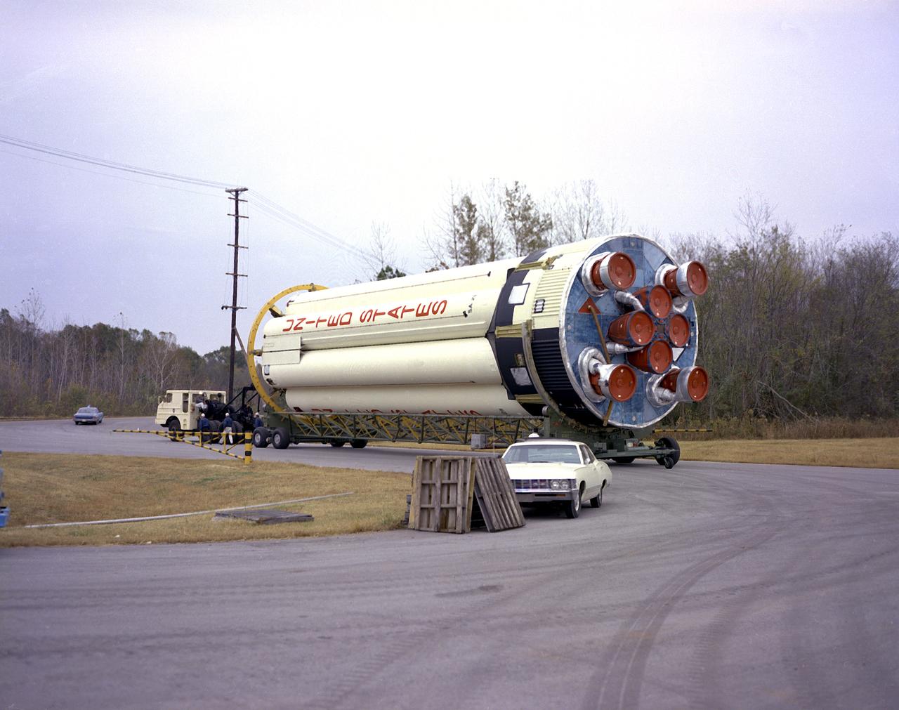
S-IB-211, the flight version of the Saturn IB launch vehicle's first (S-IVB) stage, on its way to Marshall Space Flight Center's (MSFC's) west test area. Between December 1967 and April 1968, the stage would undergo seven static test firings. The S-IB, developed by the MSFC and built by the Chrysler Corporation at the Michoud Assembly Facility near New Orleans, Louisiana, utilized eight H-1 engines and each produced 200,000 pounds of thrust.
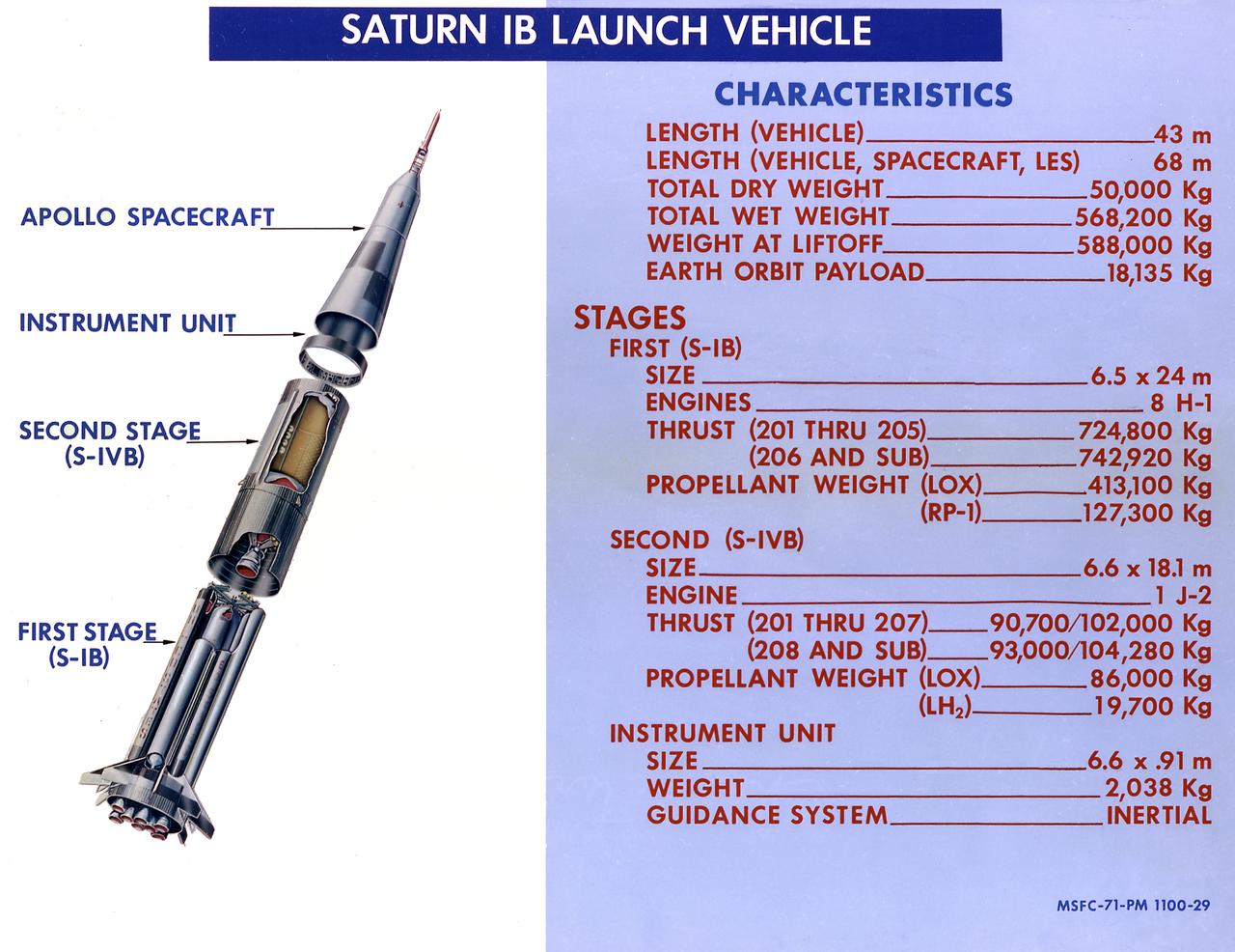
This 1968 cutaway drawing illustrates the Saturn IB launch vehicle with its two booster stages, the S-IB (first stage) and S-IVB (second stage), and provides the vital statistics in metric units. Developed by the Marshall Space Flight Center (MSFC) as an interim vehicle in MSFC's "building block" approach to the Saturn rocket development, the Saturn IB utilized Saturn I technology to further develop and refine the larger boosters and the Apollo spacecraft capabilities required for the marned lunar missions.
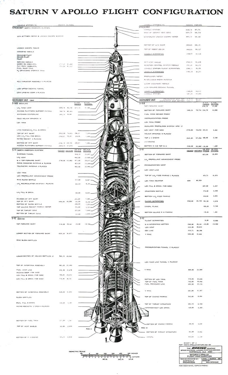
The Saturn V configuration is shown in inches and meters as illustrated by the Boeing Company. The Saturn V vehicle consisted of three stages: the S-IC (first) stage powered by five F-1 engines, the S-II (second) stage powered by five J-2 engines, the S-IVB (third) stage powered by one J-2 engine. A top for the first three stages was designed to contain the instrument unit, the guidance system, the Apollo spacecraft, and the escape system. The Apollo spacecraft consisted of the lunar module, the service module, and the command module. The Saturn V was designed perform lunar and planetary missions and it was capable of placing 280,000 pounds into Earth orbit.
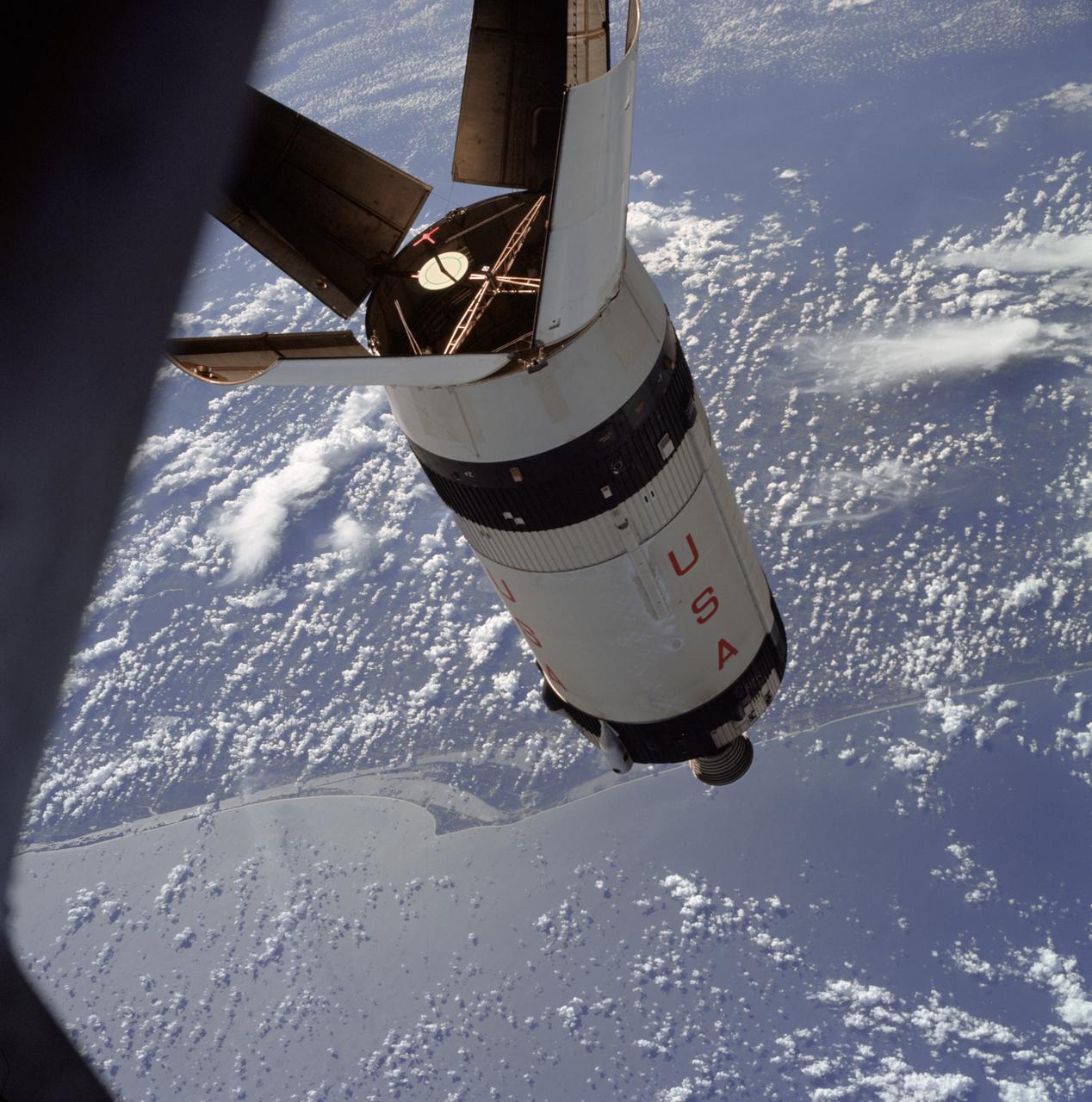
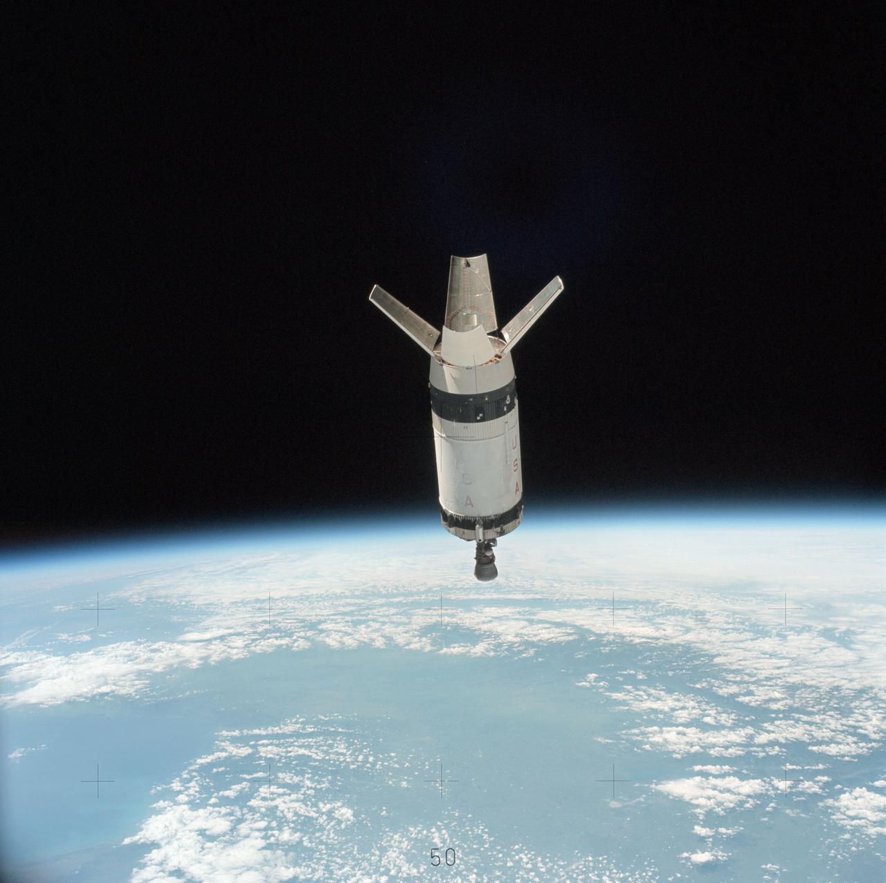
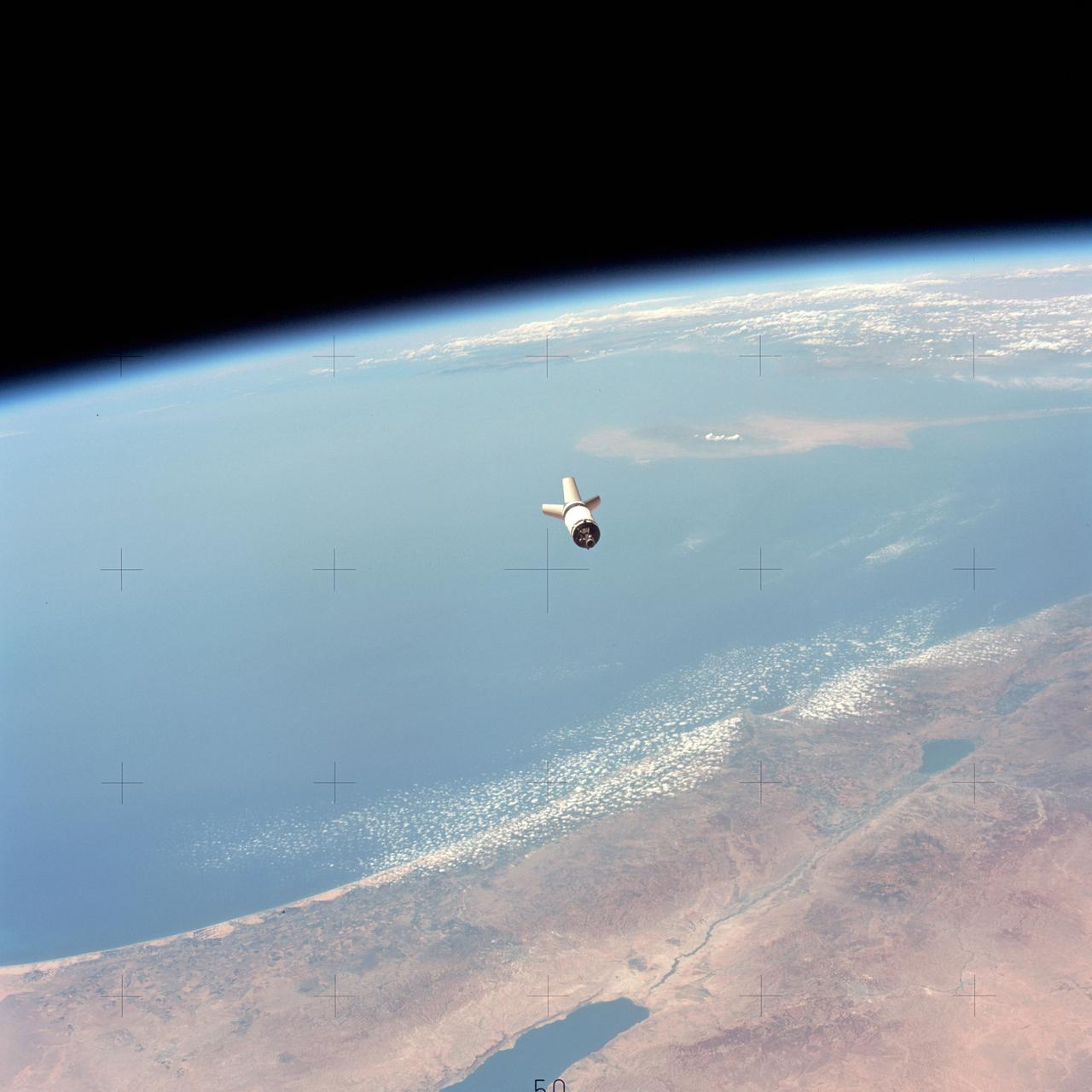
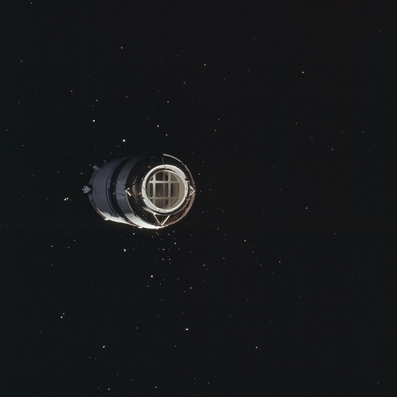
AS07-03-1545 (11 Oct. 1968) --- The expended Saturn S-IVB stage as photographed from the Apollo 7 spacecraft during transposition and docking maneuvers at an approximate altitude of 125 nautical miles, at ground elapsed time of three hours and 16 minutes (beginning of third revolution). This view is over the Atlantic Ocean off the coast of Cape Kennedy, Florida. The Florida coastline from Flagler Beach southward to Vero Beach is clearly visible in picture. Much of the Florida peninsula can be seen. Behind the open panels is the Gulf of Mexico. Distance between the Apollo 7 spacecraft and the S-IVB is approximately 100 feet. The round, white disc inside the open panels of the S-IVB is a simulated docking target similar to that used on the Lunar Module (LM) for docking during lunar missions.
AS07-03-1535 (11 Oct. 1968) --- The expended Saturn IVB stage as photographed from the Apollo 7 spacecraft during transposition and docking maneuvers at an altitude of 126 nautical miles, at ground elapsed time of three hours, 11 minutes. The round, white disc inside the open panels of the Saturn IVB is a simulated docking target similar to that used on the lunar module for docking during lunar missions. The spacecraft is directly over Odessa-Midland, Texas. The view between the two panels (area of large puffy clouds) extends southwest across Texas into the Mexican State of Chihuahua. The distance between the Apollo 7 spacecraft and the S-IVB is approximately 50 feet.

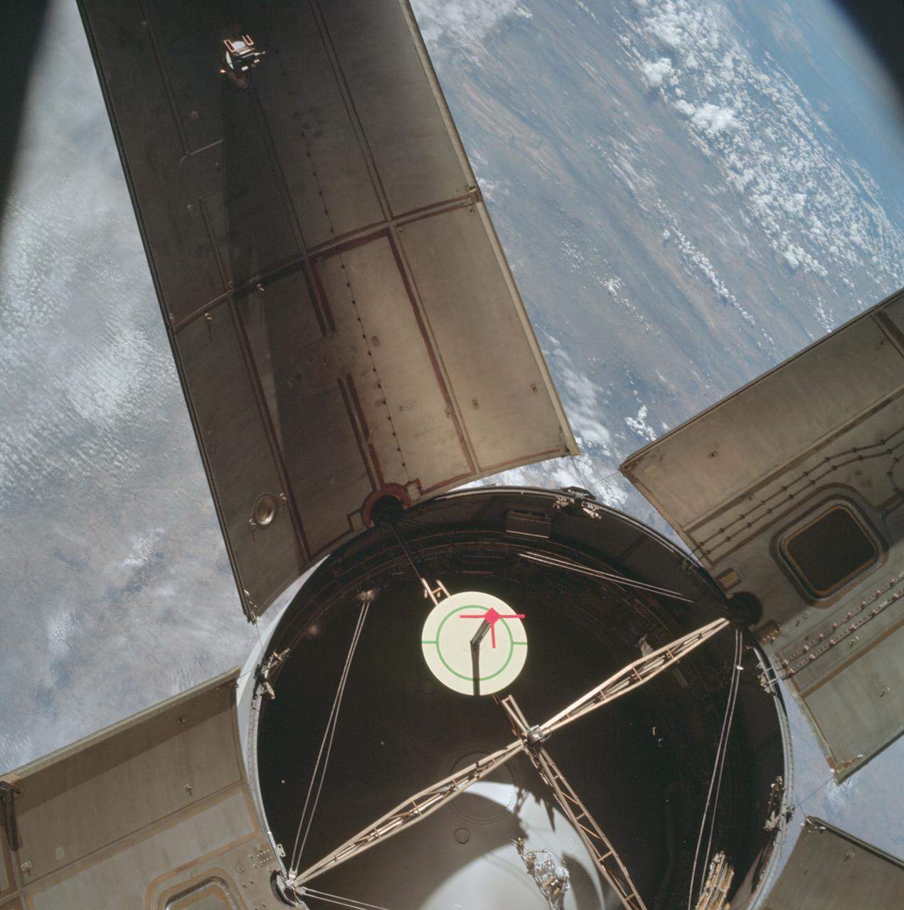
AS07-03-1538 (11 Oct. 1968) --- The expended Saturn IVB stage as photographed from the Apollo 7 spacecraft during transposition and docking maneuvers. This photograph was taken during Apollo 7's second revolution of Earth. Earth below has heavy cloud cover. The round, white disc inside the open panels of the Saturn IVB is a simulated docking target similar to that used on the lunar module for docking during lunar missions.
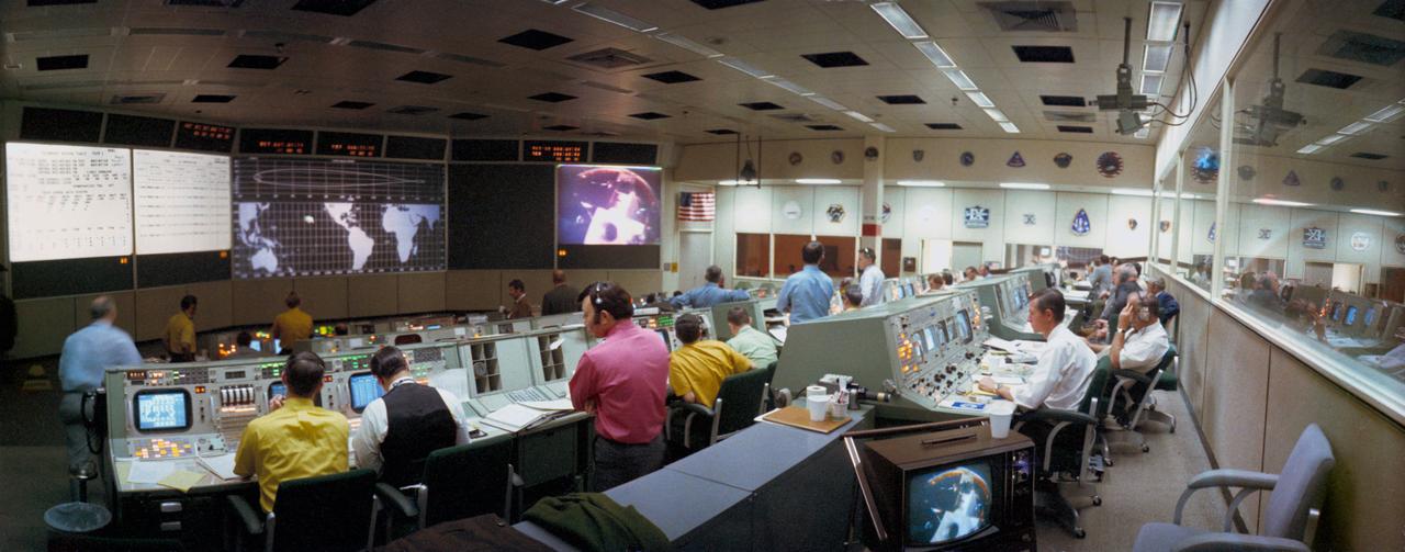
S71-17122 (31 Jan. 1971) --- A wide angle overall view of the Mission Operations Control Room (MOCR) in the Mission Control Center at the Manned spacecraft Center. This view was photographed during the first color television transmission from the Apollo 14 Command Module. Projected on the large screen at the right front of the MOCR is a view of the Apollo 14 Lunar Module, still attached to the Saturn IVB stage. The Command and Service Modules were approaching the LM/S-IVB during transposition and docking maneuvers.
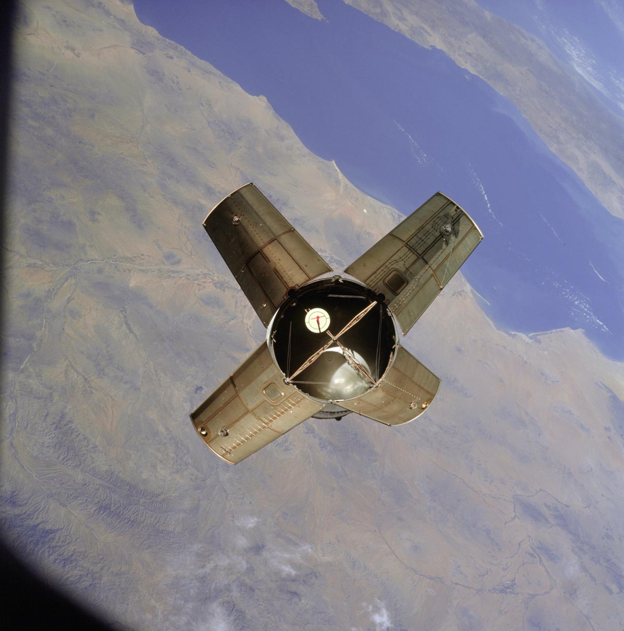
AS07-03-1531 (11 Oct. 1968) --- The expended Saturn IVB stage as photographed from the Apollo 7 spacecraft during transposition and docking maneuvers. This photograph was taken over Sonora, Mexico, during Apollo 7's second revolution of Earth. The round, white disc inside the open panels of the Saturn IVB is a simulated docking target similar to that used on the lunar module for docking during lunar missions.
AS17-148-22687 (7-19 Dec. 1972) --- View of the Lunar Module from the Apollo 17 spacecraft after transposition/docking maneuvers. The white dots surrounding the Lunar Module are debris from the Saturn S-IVB stage separation.

AS04-01-750 (9 Nov. 1967) --- Atlantic Ocean, Antarctica, looking west, as photographed from the Earth-orbital Apollo 4 (Spacecraft 017/Saturn 501) unmanned space mission. This picture was taken when the Spacecraft 017 and the Saturn S-IVB (third) stage was orbiting Earth at an altitude of 8,628 nautical miles.
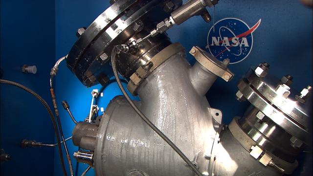
Shown is the disassembly, examination, refurbishment and testing of the LH2 ( liquid hydrogen) and LOX (liquid oxygen) vent and relief valves for the S-IVB-211 engine stage in support of the Constellation/Ares project. This image is extracted from high definition video and is the highest resolution available.
AS17-148-22688 (7-19 Dec. 1972) --- View of the Lunar Module from the Apollo 17 spacecraft after transposition/docking maneuvers. The white dots surrounding the Lunar Module are debris from the Saturn S-IVB stage separation.
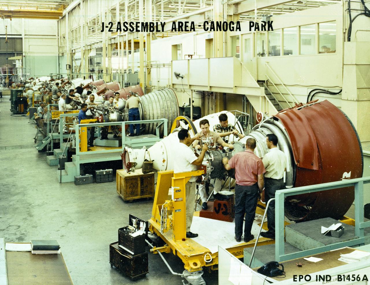
Workmen inspect a J-2 engine at Rocketdyne's Canoga Park, California production facility. The J-2, developed under the direction of the Marshall Space Flight Center, was propelled by liquid hydrogen and liquid oxygen. A single J-2 engine was used in the S-IVB stage (the second stage of the Saturn IB and third stage for the Saturn V) and a cluster of five J-2 engines was used to propel the second stage of the Saturn V, the S-II. Initially rated at 200,000 pounds of thrust, the J-2 engine was later uprated in the Saturn V program to 230,000 pounds.
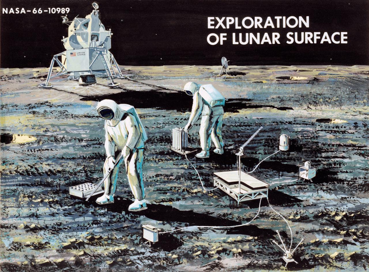
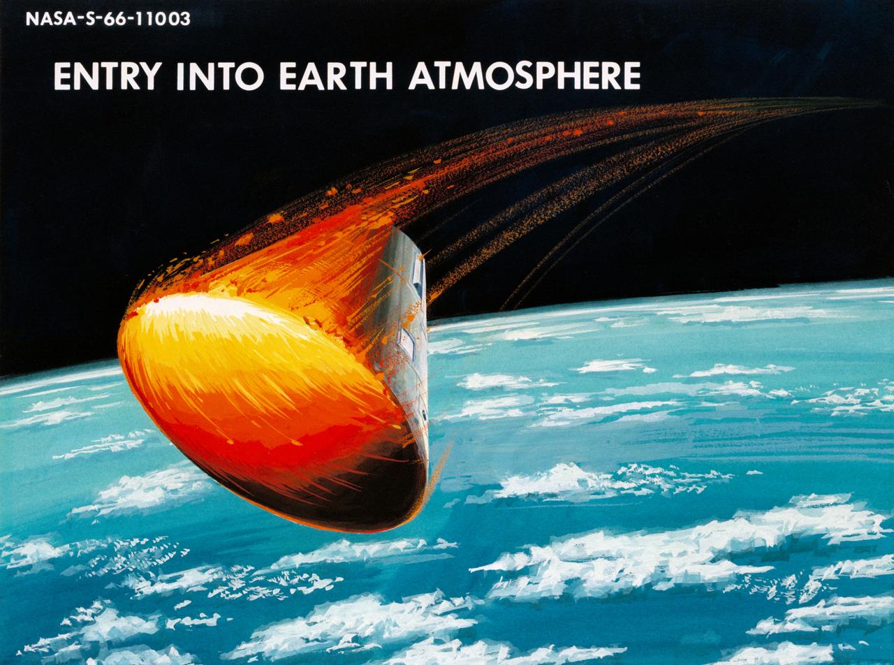
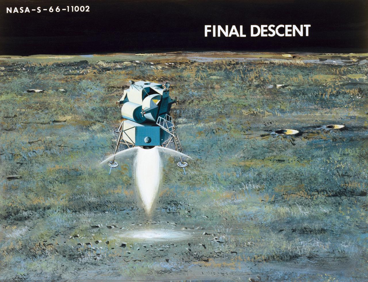
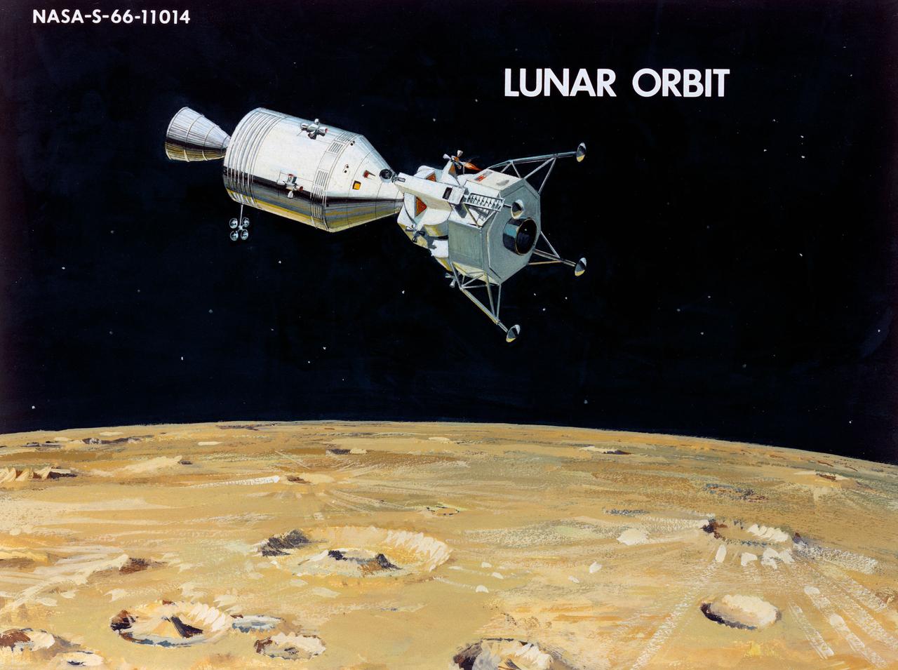
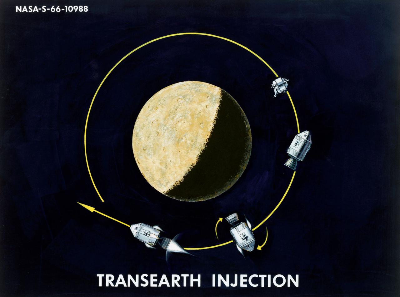
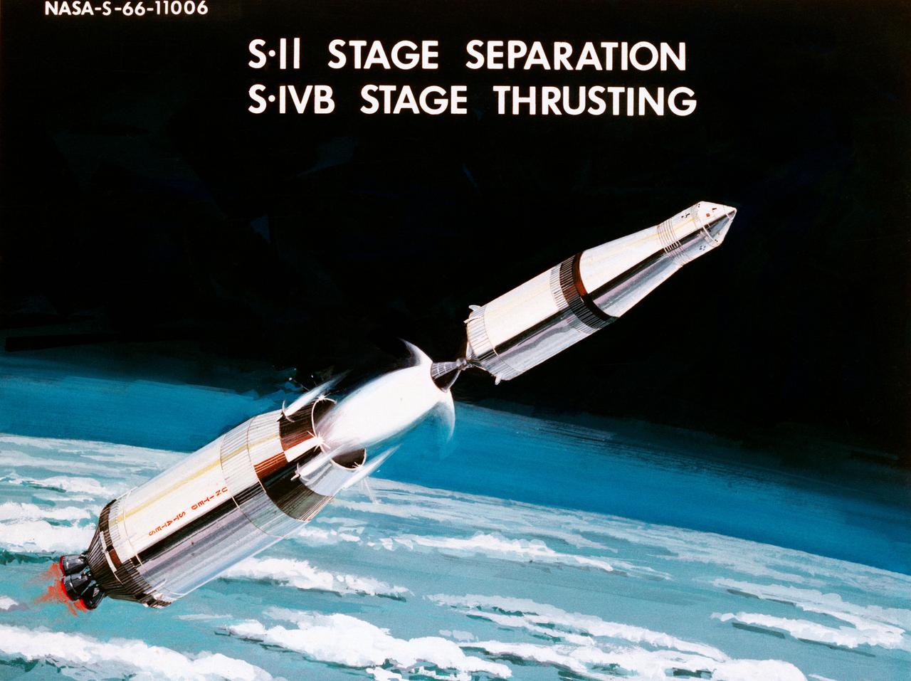
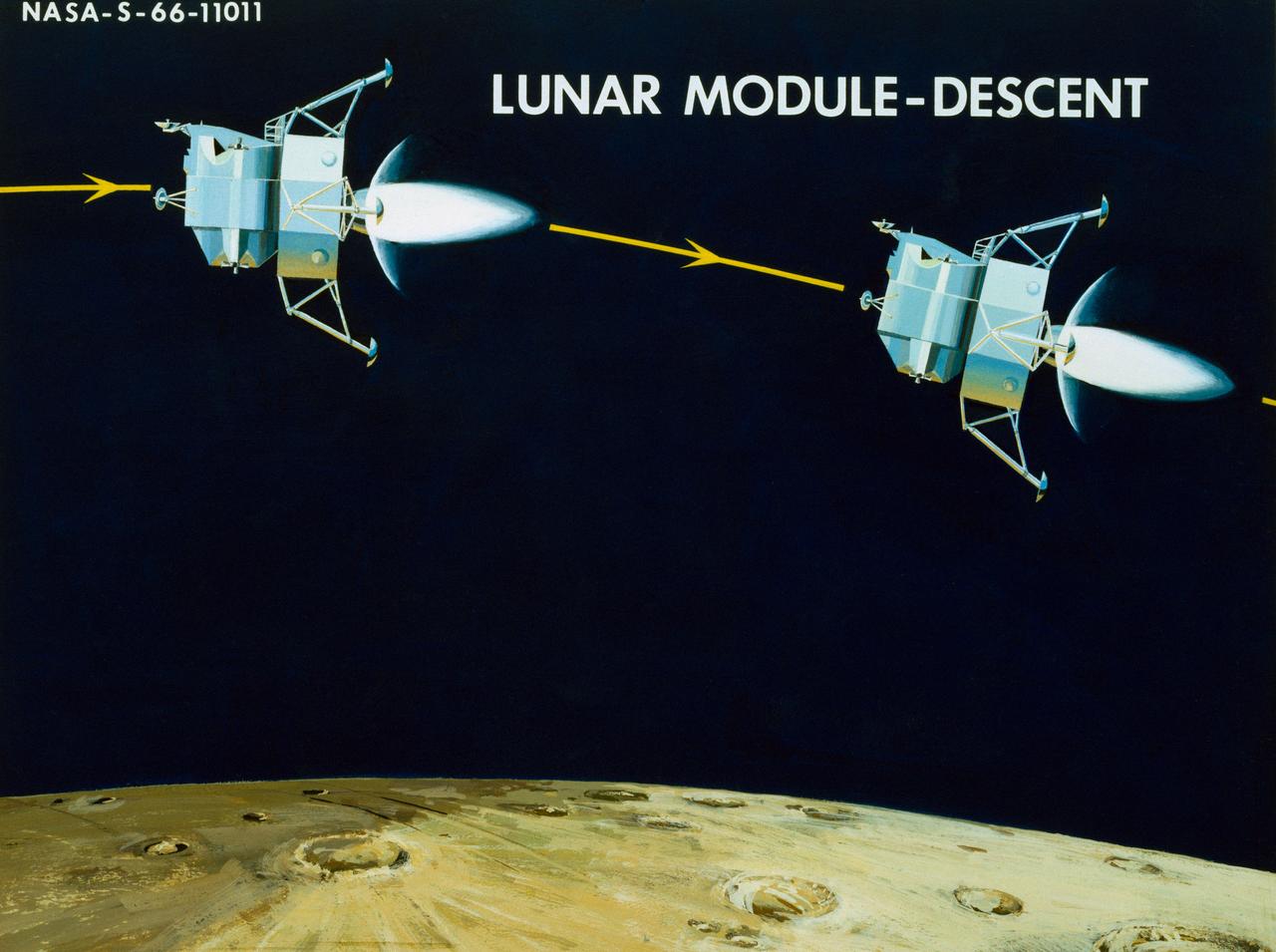
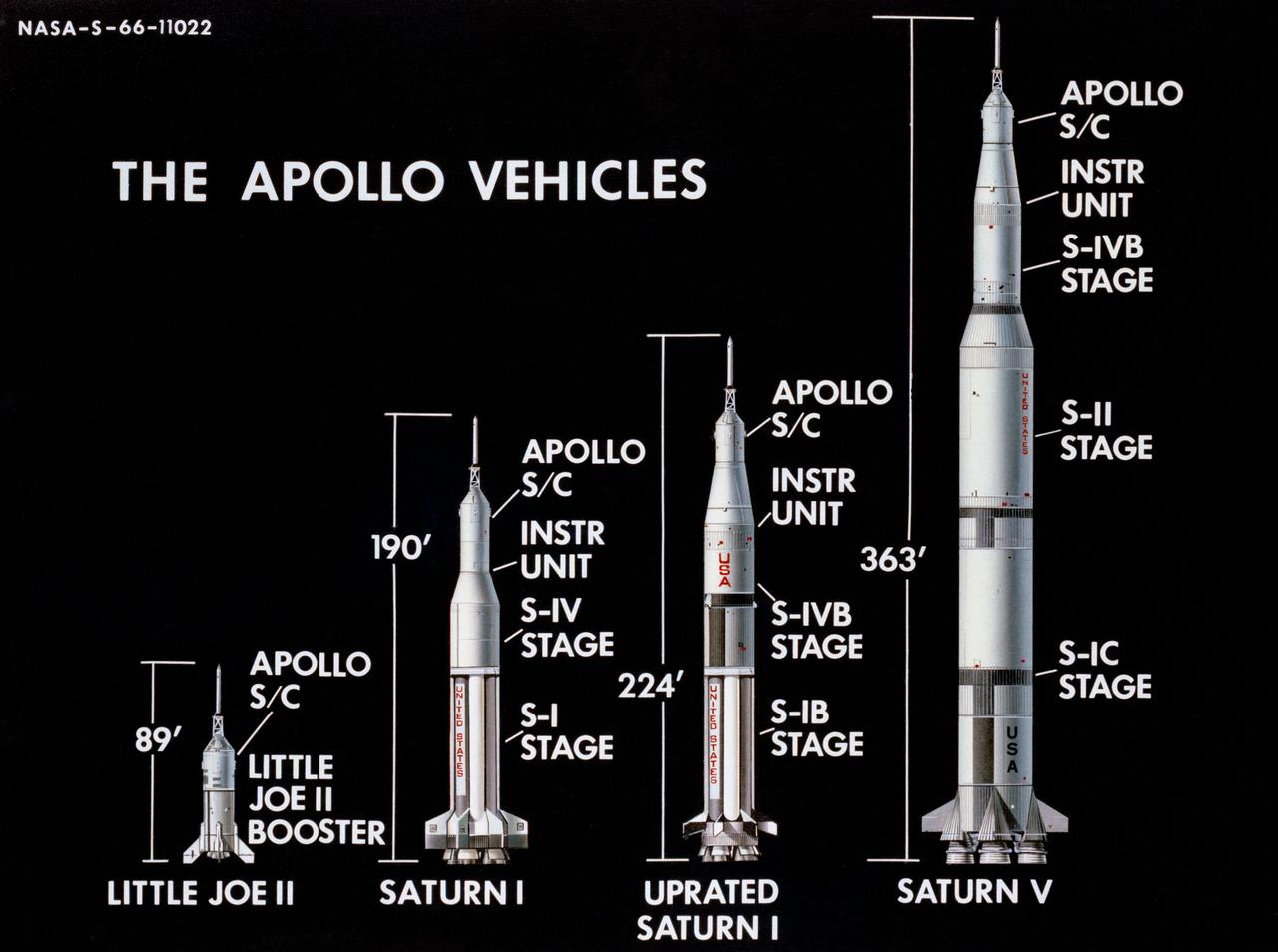
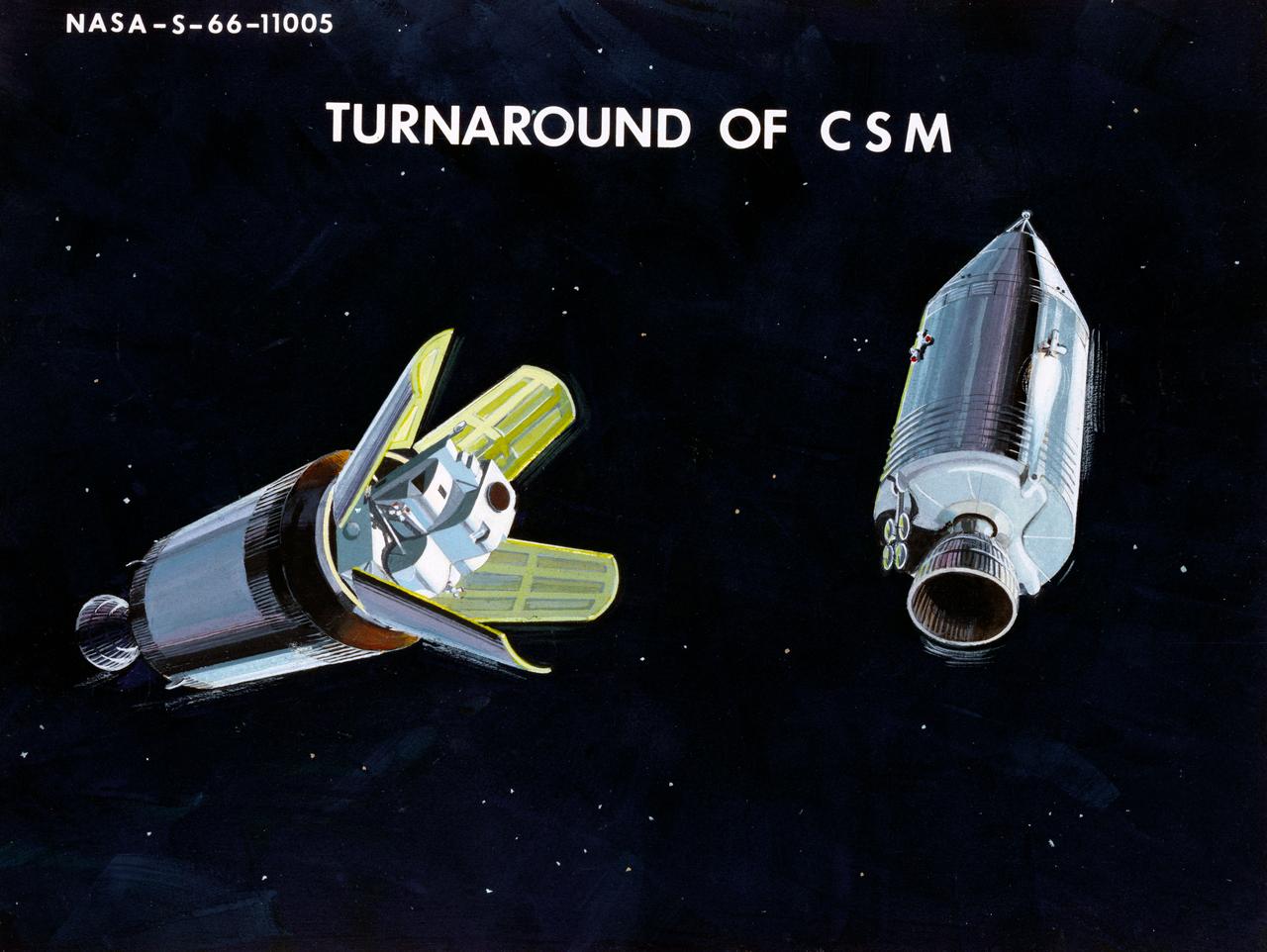
Artist Concepts, Apollo Mission: S66-10983: Ascent Stage Liftoff (S66-05094) S66-10984: Orientation During Ascent Phase (S66-05098) S66-10985: Midcourse Coast (S66-05113) S66-10986: Survey of Landing Site (S66-05117) S66-10987: Lunar Module (LM) Jettison (S66-05089) S66-10988: Trans-Earth Injection (S66-05090) S66-10989: Exploration on Lunar Surface Apollo Surface Lunar Exploration Experiment (ASLEP) S66-10990: Liftoff (S66-05125) S66-10991: Command Module (CM)-Service Module (SM) Separation (S66-05101 N/F) S66-10992: Touchdown on Lunar Surface (S66-05115) S66-10993: Transfer Orbit Insertion (S66-05111) S66-10994: Drogue Parachute Deployment S66-10995: S-IC Stage Separation S-II Stage Thrusting (S66-05099) S66-10996: Jettison Launch Escape System (S66-05114) S66-10997: Main Parachute Deployment (S66-05091) S66-10998: Mid-course correction (S66-05088) S66-10999: Lunar Orbit Insertion (S66-05086) S66-11000: Command Service Module (CSM)-LM Docked in LM Adapter-S-IVB (S66-06526) S66-11001: Docking and Separation of spacecraft from S-IVB (S66-05107) S66-11002: Final Descent (S66-05096) S66-11003: Entry into Earth Atmosphere (S66-05096) S66-11004: Deploy S/C LM Adapter-Separate CSM from LM-S-IVB (S66-06525 & 05105) S66-11005: Turnaround of CSM (S66-05104) S66-11006: S-II Stage Separation S-IVB Stage Thrusting (S66-05102) S66-11007: LM Ascent CSM Docked (S66-05100) S66-11008: Midcourse Correction SPS Mode (S66-05106) S66-11009: Earth Orbit Insertion of S-IVB & S/C (S66-05092) S66-11010: Trans-lunar Injection (S66-05116) S66-11011: LM Descent (S66-05110) S66-11012: S-IVB Stage Operations (S66-05112 N/F) S66-11013: Spacecraft Recovery (S66-05126) S66-11014: Lunar Orbit (S66-05103) S66-11015: CSM-LM Docking (S66-05095) S66-11016: Entry CM (S66-5109) S66-11017: Midcourse Corrections to Lunar Landing (S66-08486) S66-11018: Midcourse Corrections to Lunar Landing w/Overlay (S66-05083) S66-11019: Earth Launch Phase w/Overlay (S66-08485 & 05119) S66-11020: Earth Launch Phase (S66-08487 & S66-05084) S66-11022: Apollo Vehicles (S66-05127) S66-11024: Transfer to LM (S66-05082) S66-11025: Lunar Launch Phase S66-11027: Trans-earth Separation of C/M from S/M-C/M return to Earth (S66-05097) S66-11028: CSM-LM Separation, LM Descent to Moon (S66-05108) MSC, Houston, TX Also available in B&W 12/1965 - 06/1966
Artist Concepts, Apollo Mission: S66-10983: Ascent Stage Liftoff (S66-05094) S66-10984: Orientation During Ascent Phase (S66-05098) S66-10985: Midcourse Coast (S66-05113) S66-10986: Survey of Landing Site (S66-05117) S66-10987: Lunar Module (LM) Jettison (S66-05089) S66-10988: Trans-Earth Injection (S66-05090) S66-10989: Exploration on Lunar Surface Apollo Surface Lunar Exploration Experiment (ASLEP) S66-10990: Liftoff (S66-05125) S66-10991: Command Module (CM)-Service Module (SM) Separation (S66-05101 N/F) S66-10992: Touchdown on Lunar Surface (S66-05115) S66-10993: Transfer Orbit Insertion (S66-05111) S66-10994: Drogue Parachute Deployment S66-10995: S-IC Stage Separation S-II Stage Thrusting (S66-05099) S66-10996: Jettison Launch Escape System (S66-05114) S66-10997: Main Parachute Deployment (S66-05091) S66-10998: Mid-course correction (S66-05088) S66-10999: Lunar Orbit Insertion (S66-05086) S66-11000: Command Service Module (CSM)-LM Docked in LM Adapter-S-IVB (S66-06526) S66-11001: Docking and Separation of spacecraft from S-IVB (S66-05107) S66-11002: Final Descent (S66-05096) S66-11003: Entry into Earth Atmosphere (S66-05096) S66-11004: Deploy S/C LM Adapter-Separate CSM from LM-S-IVB (S66-06525 & 05105) S66-11005: Turnaround of CSM (S66-05104) S66-11006: S-II Stage Separation S-IVB Stage Thrusting (S66-05102) S66-11007: LM Ascent CSM Docked (S66-05100) S66-11008: Midcourse Correction SPS Mode (S66-05106) S66-11009: Earth Orbit Insertion of S-IVB & S/C (S66-05092) S66-11010: Trans-lunar Injection (S66-05116) S66-11011: LM Descent (S66-05110) S66-11012: S-IVB Stage Operations (S66-05112 N/F) S66-11013: Spacecraft Recovery (S66-05126) S66-11014: Lunar Orbit (S66-05103) S66-11015: CSM-LM Docking (S66-05095) S66-11016: Entry CM (S66-5109) S66-11017: Midcourse Corrections to Lunar Landing (S66-08486) S66-11018: Midcourse Corrections to Lunar Landing w/Overlay (S66-05083) S66-11019: Earth Launch Phase w/Overlay (S66-08485 & 05119) S66-11020: Earth Launch Phase (S66-08487 & S66-05084) S66-11022: Apollo Vehicles (S66-05127) S66-11024: Transfer to LM (S66-05082) S66-11025: Lunar Launch Phase S66-11027: Trans-earth Separation of C/M from S/M-C/M return to Earth (S66-05097) S66-11028: CSM-LM Separation, LM Descent to Moon (S66-05108) MSC, Houston, TX Also available in B&W 12/1965 - 06/1966
Artist Concepts, Apollo Mission: S66-10983: Ascent Stage Liftoff (S66-05094) S66-10984: Orientation During Ascent Phase (S66-05098) S66-10985: Midcourse Coast (S66-05113) S66-10986: Survey of Landing Site (S66-05117) S66-10987: Lunar Module (LM) Jettison (S66-05089) S66-10988: Trans-Earth Injection (S66-05090) S66-10989: Exploration on Lunar Surface Apollo Surface Lunar Exploration Experiment (ASLEP) S66-10990: Liftoff (S66-05125) S66-10991: Command Module (CM)-Service Module (SM) Separation (S66-05101 N/F) S66-10992: Touchdown on Lunar Surface (S66-05115) S66-10993: Transfer Orbit Insertion (S66-05111) S66-10994: Drogue Parachute Deployment S66-10995: S-IC Stage Separation S-II Stage Thrusting (S66-05099) S66-10996: Jettison Launch Escape System (S66-05114) S66-10997: Main Parachute Deployment (S66-05091) S66-10998: Mid-course correction (S66-05088) S66-10999: Lunar Orbit Insertion (S66-05086) S66-11000: Command Service Module (CSM)-LM Docked in LM Adapter-S-IVB (S66-06526) S66-11001: Docking and Separation of spacecraft from S-IVB (S66-05107) S66-11002: Final Descent (S66-05096) S66-11003: Entry into Earth Atmosphere (S66-05096) S66-11004: Deploy S/C LM Adapter-Separate CSM from LM-S-IVB (S66-06525 & 05105) S66-11005: Turnaround of CSM (S66-05104) S66-11006: S-II Stage Separation S-IVB Stage Thrusting (S66-05102) S66-11007: LM Ascent CSM Docked (S66-05100) S66-11008: Midcourse Correction SPS Mode (S66-05106) S66-11009: Earth Orbit Insertion of S-IVB & S/C (S66-05092) S66-11010: Trans-lunar Injection (S66-05116) S66-11011: LM Descent (S66-05110) S66-11012: S-IVB Stage Operations (S66-05112 N/F) S66-11013: Spacecraft Recovery (S66-05126) S66-11014: Lunar Orbit (S66-05103) S66-11015: CSM-LM Docking (S66-05095) S66-11016: Entry CM (S66-5109) S66-11017: Midcourse Corrections to Lunar Landing (S66-08486) S66-11018: Midcourse Corrections to Lunar Landing w/Overlay (S66-05083) S66-11019: Earth Launch Phase w/Overlay (S66-08485 & 05119) S66-11020: Earth Launch Phase (S66-08487 & S66-05084) S66-11022: Apollo Vehicles (S66-05127) S66-11024: Transfer to LM (S66-05082) S66-11025: Lunar Launch Phase S66-11027: Trans-earth Separation of C/M from S/M-C/M return to Earth (S66-05097) S66-11028: CSM-LM Separation, LM Descent to Moon (S66-05108) MSC, Houston, TX Also available in B&W 12/1965 - 06/1966
Artist Concepts, Apollo Mission: S66-10983: Ascent Stage Liftoff (S66-05094) S66-10984: Orientation During Ascent Phase (S66-05098) S66-10985: Midcourse Coast (S66-05113) S66-10986: Survey of Landing Site (S66-05117) S66-10987: Lunar Module (LM) Jettison (S66-05089) S66-10988: Trans-Earth Injection (S66-05090) S66-10989: Exploration on Lunar Surface Apollo Surface Lunar Exploration Experiment (ASLEP) S66-10990: Liftoff (S66-05125) S66-10991: Command Module (CM)-Service Module (SM) Separation (S66-05101 N/F) S66-10992: Touchdown on Lunar Surface (S66-05115) S66-10993: Transfer Orbit Insertion (S66-05111) S66-10994: Drogue Parachute Deployment S66-10995: S-IC Stage Separation S-II Stage Thrusting (S66-05099) S66-10996: Jettison Launch Escape System (S66-05114) S66-10997: Main Parachute Deployment (S66-05091) S66-10998: Mid-course correction (S66-05088) S66-10999: Lunar Orbit Insertion (S66-05086) S66-11000: Command Service Module (CSM)-LM Docked in LM Adapter-S-IVB (S66-06526) S66-11001: Docking and Separation of spacecraft from S-IVB (S66-05107) S66-11002: Final Descent (S66-05096) S66-11003: Entry into Earth Atmosphere (S66-05096) S66-11004: Deploy S/C LM Adapter-Separate CSM from LM-S-IVB (S66-06525 & 05105) S66-11005: Turnaround of CSM (S66-05104) S66-11006: S-II Stage Separation S-IVB Stage Thrusting (S66-05102) S66-11007: LM Ascent CSM Docked (S66-05100) S66-11008: Midcourse Correction SPS Mode (S66-05106) S66-11009: Earth Orbit Insertion of S-IVB & S/C (S66-05092) S66-11010: Trans-lunar Injection (S66-05116) S66-11011: LM Descent (S66-05110) S66-11012: S-IVB Stage Operations (S66-05112 N/F) S66-11013: Spacecraft Recovery (S66-05126) S66-11014: Lunar Orbit (S66-05103) S66-11015: CSM-LM Docking (S66-05095) S66-11016: Entry CM (S66-5109) S66-11017: Midcourse Corrections to Lunar Landing (S66-08486) S66-11018: Midcourse Corrections to Lunar Landing w/Overlay (S66-05083) S66-11019: Earth Launch Phase w/Overlay (S66-08485 & 05119) S66-11020: Earth Launch Phase (S66-08487 & S66-05084) S66-11022: Apollo Vehicles (S66-05127) S66-11024: Transfer to LM (S66-05082) S66-11025: Lunar Launch Phase S66-11027: Trans-earth Separation of C/M from S/M-C/M return to Earth (S66-05097) S66-11028: CSM-LM Separation, LM Descent to Moon (S66-05108) MSC, Houston, TX Also available in B&W 12/1965 - 06/1966
Artist Concepts, Apollo Mission: S66-10983: Ascent Stage Liftoff (S66-05094) S66-10984: Orientation During Ascent Phase (S66-05098) S66-10985: Midcourse Coast (S66-05113) S66-10986: Survey of Landing Site (S66-05117) S66-10987: Lunar Module (LM) Jettison (S66-05089) S66-10988: Trans-Earth Injection (S66-05090) S66-10989: Exploration on Lunar Surface Apollo Surface Lunar Exploration Experiment (ASLEP) S66-10990: Liftoff (S66-05125) S66-10991: Command Module (CM)-Service Module (SM) Separation (S66-05101 N/F) S66-10992: Touchdown on Lunar Surface (S66-05115) S66-10993: Transfer Orbit Insertion (S66-05111) S66-10994: Drogue Parachute Deployment S66-10995: S-IC Stage Separation S-II Stage Thrusting (S66-05099) S66-10996: Jettison Launch Escape System (S66-05114) S66-10997: Main Parachute Deployment (S66-05091) S66-10998: Mid-course correction (S66-05088) S66-10999: Lunar Orbit Insertion (S66-05086) S66-11000: Command Service Module (CSM)-LM Docked in LM Adapter-S-IVB (S66-06526) S66-11001: Docking and Separation of spacecraft from S-IVB (S66-05107) S66-11002: Final Descent (S66-05096) S66-11003: Entry into Earth Atmosphere (S66-05096) S66-11004: Deploy S/C LM Adapter-Separate CSM from LM-S-IVB (S66-06525 & 05105) S66-11005: Turnaround of CSM (S66-05104) S66-11006: S-II Stage Separation S-IVB Stage Thrusting (S66-05102) S66-11007: LM Ascent CSM Docked (S66-05100) S66-11008: Midcourse Correction SPS Mode (S66-05106) S66-11009: Earth Orbit Insertion of S-IVB & S/C (S66-05092) S66-11010: Trans-lunar Injection (S66-05116) S66-11011: LM Descent (S66-05110) S66-11012: S-IVB Stage Operations (S66-05112 N/F) S66-11013: Spacecraft Recovery (S66-05126) S66-11014: Lunar Orbit (S66-05103) S66-11015: CSM-LM Docking (S66-05095) S66-11016: Entry CM (S66-5109) S66-11017: Midcourse Corrections to Lunar Landing (S66-08486) S66-11018: Midcourse Corrections to Lunar Landing w/Overlay (S66-05083) S66-11019: Earth Launch Phase w/Overlay (S66-08485 & 05119) S66-11020: Earth Launch Phase (S66-08487 & S66-05084) S66-11022: Apollo Vehicles (S66-05127) S66-11024: Transfer to LM (S66-05082) S66-11025: Lunar Launch Phase S66-11027: Trans-earth Separation of C/M from S/M-C/M return to Earth (S66-05097) S66-11028: CSM-LM Separation, LM Descent to Moon (S66-05108) MSC, Houston, TX Also available in B&W 12/1965 - 06/1966
Artist Concepts, Apollo Mission: S66-10983: Ascent Stage Liftoff (S66-05094) S66-10984: Orientation During Ascent Phase (S66-05098) S66-10985: Midcourse Coast (S66-05113) S66-10986: Survey of Landing Site (S66-05117) S66-10987: Lunar Module (LM) Jettison (S66-05089) S66-10988: Trans-Earth Injection (S66-05090) S66-10989: Exploration on Lunar Surface Apollo Surface Lunar Exploration Experiment (ASLEP) S66-10990: Liftoff (S66-05125) S66-10991: Command Module (CM)-Service Module (SM) Separation (S66-05101 N/F) S66-10992: Touchdown on Lunar Surface (S66-05115) S66-10993: Transfer Orbit Insertion (S66-05111) S66-10994: Drogue Parachute Deployment S66-10995: S-IC Stage Separation S-II Stage Thrusting (S66-05099) S66-10996: Jettison Launch Escape System (S66-05114) S66-10997: Main Parachute Deployment (S66-05091) S66-10998: Mid-course correction (S66-05088) S66-10999: Lunar Orbit Insertion (S66-05086) S66-11000: Command Service Module (CSM)-LM Docked in LM Adapter-S-IVB (S66-06526) S66-11001: Docking and Separation of spacecraft from S-IVB (S66-05107) S66-11002: Final Descent (S66-05096) S66-11003: Entry into Earth Atmosphere (S66-05096) S66-11004: Deploy S/C LM Adapter-Separate CSM from LM-S-IVB (S66-06525 & 05105) S66-11005: Turnaround of CSM (S66-05104) S66-11006: S-II Stage Separation S-IVB Stage Thrusting (S66-05102) S66-11007: LM Ascent CSM Docked (S66-05100) S66-11008: Midcourse Correction SPS Mode (S66-05106) S66-11009: Earth Orbit Insertion of S-IVB & S/C (S66-05092) S66-11010: Trans-lunar Injection (S66-05116) S66-11011: LM Descent (S66-05110) S66-11012: S-IVB Stage Operations (S66-05112 N/F) S66-11013: Spacecraft Recovery (S66-05126) S66-11014: Lunar Orbit (S66-05103) S66-11015: CSM-LM Docking (S66-05095) S66-11016: Entry CM (S66-5109) S66-11017: Midcourse Corrections to Lunar Landing (S66-08486) S66-11018: Midcourse Corrections to Lunar Landing w/Overlay (S66-05083) S66-11019: Earth Launch Phase w/Overlay (S66-08485 & 05119) S66-11020: Earth Launch Phase (S66-08487 & S66-05084) S66-11022: Apollo Vehicles (S66-05127) S66-11024: Transfer to LM (S66-05082) S66-11025: Lunar Launch Phase S66-11027: Trans-earth Separation of C/M from S/M-C/M return to Earth (S66-05097) S66-11028: CSM-LM Separation, LM Descent to Moon (S66-05108) MSC, Houston, TX Also available in B&W 12/1965 - 06/1966

Artist Concepts, Apollo Mission: S66-10983: Ascent Stage Liftoff (S66-05094) S66-10984: Orientation During Ascent Phase (S66-05098) S66-10985: Midcourse Coast (S66-05113) S66-10986: Survey of Landing Site (S66-05117) S66-10987: Lunar Module (LM) Jettison (S66-05089) S66-10988: Trans-Earth Injection (S66-05090) S66-10989: Exploration on Lunar Surface Apollo Surface Lunar Exploration Experiment (ASLEP) S66-10990: Liftoff (S66-05125) S66-10991: Command Module (CM)-Service Module (SM) Separation (S66-05101 N/F) S66-10992: Touchdown on Lunar Surface (S66-05115) S66-10993: Transfer Orbit Insertion (S66-05111) S66-10994: Drogue Parachute Deployment S66-10995: S-IC Stage Separation S-II Stage Thrusting (S66-05099) S66-10996: Jettison Launch Escape System (S66-05114) S66-10997: Main Parachute Deployment (S66-05091) S66-10998: Mid-course correction (S66-05088) S66-10999: Lunar Orbit Insertion (S66-05086) S66-11000: Command Service Module (CSM)-LM Docked in LM Adapter-S-IVB (S66-06526) S66-11001: Docking and Separation of spacecraft from S-IVB (S66-05107) S66-11002: Final Descent (S66-05096) S66-11003: Entry into Earth Atmosphere (S66-05096) S66-11004: Deploy S/C LM Adapter-Separate CSM from LM-S-IVB (S66-06525 & 05105) S66-11005: Turnaround of CSM (S66-05104) S66-11006: S-II Stage Separation S-IVB Stage Thrusting (S66-05102) S66-11007: LM Ascent CSM Docked (S66-05100) S66-11008: Midcourse Correction SPS Mode (S66-05106) S66-11009: Earth Orbit Insertion of S-IVB & S/C (S66-05092) S66-11010: Trans-lunar Injection (S66-05116) S66-11011: LM Descent (S66-05110) S66-11012: S-IVB Stage Operations (S66-05112 N/F) S66-11013: Spacecraft Recovery (S66-05126) S66-11014: Lunar Orbit (S66-05103) S66-11015: CSM-LM Docking (S66-05095) S66-11016: Entry CM (S66-5109) S66-11017: Midcourse Corrections to Lunar Landing (S66-08486) S66-11018: Midcourse Corrections to Lunar Landing w/Overlay (S66-05083) S66-11019: Earth Launch Phase w/Overlay (S66-08485 & 05119) S66-11020: Earth Launch Phase (S66-08487 & S66-05084) S66-11022: Apollo Vehicles (S66-05127) S66-11024: Transfer to LM (S66-05082) S66-11025: Lunar Launch Phase S66-11027: Trans-earth Separation of C/M from S/M-C/M return to Earth (S66-05097) S66-11028: CSM-LM Separation, LM Descent to Moon (S66-05108) MSC, Houston, TX Also available in B&W 12/1965 - 06/1966
Artist Concepts, Apollo Mission: S66-10983: Ascent Stage Liftoff (S66-05094) S66-10984: Orientation During Ascent Phase (S66-05098) S66-10985: Midcourse Coast (S66-05113) S66-10986: Survey of Landing Site (S66-05117) S66-10987: Lunar Module (LM) Jettison (S66-05089) S66-10988: Trans-Earth Injection (S66-05090) S66-10989: Exploration on Lunar Surface Apollo Surface Lunar Exploration Experiment (ASLEP) S66-10990: Liftoff (S66-05125) S66-10991: Command Module (CM)-Service Module (SM) Separation (S66-05101 N/F) S66-10992: Touchdown on Lunar Surface (S66-05115) S66-10993: Transfer Orbit Insertion (S66-05111) S66-10994: Drogue Parachute Deployment S66-10995: S-IC Stage Separation S-II Stage Thrusting (S66-05099) S66-10996: Jettison Launch Escape System (S66-05114) S66-10997: Main Parachute Deployment (S66-05091) S66-10998: Mid-course correction (S66-05088) S66-10999: Lunar Orbit Insertion (S66-05086) S66-11000: Command Service Module (CSM)-LM Docked in LM Adapter-S-IVB (S66-06526) S66-11001: Docking and Separation of spacecraft from S-IVB (S66-05107) S66-11002: Final Descent (S66-05096) S66-11003: Entry into Earth Atmosphere (S66-05096) S66-11004: Deploy S/C LM Adapter-Separate CSM from LM-S-IVB (S66-06525 & 05105) S66-11005: Turnaround of CSM (S66-05104) S66-11006: S-II Stage Separation S-IVB Stage Thrusting (S66-05102) S66-11007: LM Ascent CSM Docked (S66-05100) S66-11008: Midcourse Correction SPS Mode (S66-05106) S66-11009: Earth Orbit Insertion of S-IVB & S/C (S66-05092) S66-11010: Trans-lunar Injection (S66-05116) S66-11011: LM Descent (S66-05110) S66-11012: S-IVB Stage Operations (S66-05112 N/F) S66-11013: Spacecraft Recovery (S66-05126) S66-11014: Lunar Orbit (S66-05103) S66-11015: CSM-LM Docking (S66-05095) S66-11016: Entry CM (S66-5109) S66-11017: Midcourse Corrections to Lunar Landing (S66-08486) S66-11018: Midcourse Corrections to Lunar Landing w/Overlay (S66-05083) S66-11019: Earth Launch Phase w/Overlay (S66-08485 & 05119) S66-11020: Earth Launch Phase (S66-08487 & S66-05084) S66-11022: Apollo Vehicles (S66-05127) S66-11024: Transfer to LM (S66-05082) S66-11025: Lunar Launch Phase S66-11027: Trans-earth Separation of C/M from S/M-C/M return to Earth (S66-05097) S66-11028: CSM-LM Separation, LM Descent to Moon (S66-05108) MSC, Houston, TX Also available in B&W 12/1965 - 06/1966

Artist Concepts, Apollo Mission: S66-10983: Ascent Stage Liftoff (S66-05094) S66-10984: Orientation During Ascent Phase (S66-05098) S66-10985: Midcourse Coast (S66-05113) S66-10986: Survey of Landing Site (S66-05117) S66-10987: Lunar Module (LM) Jettison (S66-05089) S66-10988: Trans-Earth Injection (S66-05090) S66-10989: Exploration on Lunar Surface Apollo Surface Lunar Exploration Experiment (ASLEP) S66-10990: Liftoff (S66-05125) S66-10991: Command Module (CM)-Service Module (SM) Separation (S66-05101 N/F) S66-10992: Touchdown on Lunar Surface (S66-05115) S66-10993: Transfer Orbit Insertion (S66-05111) S66-10994: Drogue Parachute Deployment S66-10995: S-IC Stage Separation S-II Stage Thrusting (S66-05099) S66-10996: Jettison Launch Escape System (S66-05114) S66-10997: Main Parachute Deployment (S66-05091) S66-10998: Mid-course correction (S66-05088) S66-10999: Lunar Orbit Insertion (S66-05086) S66-11000: Command Service Module (CSM)-LM Docked in LM Adapter-S-IVB (S66-06526) S66-11001: Docking and Separation of spacecraft from S-IVB (S66-05107) S66-11002: Final Descent (S66-05096) S66-11003: Entry into Earth Atmosphere (S66-05096) S66-11004: Deploy S/C LM Adapter-Separate CSM from LM-S-IVB (S66-06525 & 05105) S66-11005: Turnaround of CSM (S66-05104) S66-11006: S-II Stage Separation S-IVB Stage Thrusting (S66-05102) S66-11007: LM Ascent CSM Docked (S66-05100) S66-11008: Midcourse Correction SPS Mode (S66-05106) S66-11009: Earth Orbit Insertion of S-IVB & S/C (S66-05092) S66-11010: Trans-lunar Injection (S66-05116) S66-11011: LM Descent (S66-05110) S66-11012: S-IVB Stage Operations (S66-05112 N/F) S66-11013: Spacecraft Recovery (S66-05126) S66-11014: Lunar Orbit (S66-05103) S66-11015: CSM-LM Docking (S66-05095) S66-11016: Entry CM (S66-5109) S66-11017: Midcourse Corrections to Lunar Landing (S66-08486) S66-11018: Midcourse Corrections to Lunar Landing w/Overlay (S66-05083) S66-11019: Earth Launch Phase w/Overlay (S66-08485 & 05119) S66-11020: Earth Launch Phase (S66-08487 & S66-05084) S66-11022: Apollo Vehicles (S66-05127) S66-11024: Transfer to LM (S66-05082) S66-11025: Lunar Launch Phase S66-11027: Trans-earth Separation of C/M from S/M-C/M return to Earth (S66-05097) S66-11028: CSM-LM Separation, LM Descent to Moon (S66-05108) MSC, Houston, TX Also available in B&W 12/1965 - 06/1966
Artist Concepts, Apollo Mission: S66-10983: Ascent Stage Liftoff (S66-05094) S66-10984: Orientation During Ascent Phase (S66-05098) S66-10985: Midcourse Coast (S66-05113) S66-10986: Survey of Landing Site (S66-05117) S66-10987: Lunar Module (LM) Jettison (S66-05089) S66-10988: Trans-Earth Injection (S66-05090) S66-10989: Exploration on Lunar Surface Apollo Surface Lunar Exploration Experiment (ASLEP) S66-10990: Liftoff (S66-05125) S66-10991: Command Module (CM)-Service Module (SM) Separation (S66-05101 N/F) S66-10992: Touchdown on Lunar Surface (S66-05115) S66-10993: Transfer Orbit Insertion (S66-05111) S66-10994: Drogue Parachute Deployment S66-10995: S-IC Stage Separation S-II Stage Thrusting (S66-05099) S66-10996: Jettison Launch Escape System (S66-05114) S66-10997: Main Parachute Deployment (S66-05091) S66-10998: Mid-course correction (S66-05088) S66-10999: Lunar Orbit Insertion (S66-05086) S66-11000: Command Service Module (CSM)-LM Docked in LM Adapter-S-IVB (S66-06526) S66-11001: Docking and Separation of spacecraft from S-IVB (S66-05107) S66-11002: Final Descent (S66-05096) S66-11003: Entry into Earth Atmosphere (S66-05096) S66-11004: Deploy S/C LM Adapter-Separate CSM from LM-S-IVB (S66-06525 & 05105) S66-11005: Turnaround of CSM (S66-05104) S66-11006: S-II Stage Separation S-IVB Stage Thrusting (S66-05102) S66-11007: LM Ascent CSM Docked (S66-05100) S66-11008: Midcourse Correction SPS Mode (S66-05106) S66-11009: Earth Orbit Insertion of S-IVB & S/C (S66-05092) S66-11010: Trans-lunar Injection (S66-05116) S66-11011: LM Descent (S66-05110) S66-11012: S-IVB Stage Operations (S66-05112 N/F) S66-11013: Spacecraft Recovery (S66-05126) S66-11014: Lunar Orbit (S66-05103) S66-11015: CSM-LM Docking (S66-05095) S66-11016: Entry CM (S66-5109) S66-11017: Midcourse Corrections to Lunar Landing (S66-08486) S66-11018: Midcourse Corrections to Lunar Landing w/Overlay (S66-05083) S66-11019: Earth Launch Phase w/Overlay (S66-08485 & 05119) S66-11020: Earth Launch Phase (S66-08487 & S66-05084) S66-11022: Apollo Vehicles (S66-05127) S66-11024: Transfer to LM (S66-05082) S66-11025: Lunar Launch Phase S66-11027: Trans-earth Separation of C/M from S/M-C/M return to Earth (S66-05097) S66-11028: CSM-LM Separation, LM Descent to Moon (S66-05108) MSC, Houston, TX Also available in B&W 12/1965 - 06/1966
Artist Concepts, Apollo Mission: S66-10983: Ascent Stage Liftoff (S66-05094) S66-10984: Orientation During Ascent Phase (S66-05098) S66-10985: Midcourse Coast (S66-05113) S66-10986: Survey of Landing Site (S66-05117) S66-10987: Lunar Module (LM) Jettison (S66-05089) S66-10988: Trans-Earth Injection (S66-05090) S66-10989: Exploration on Lunar Surface Apollo Surface Lunar Exploration Experiment (ASLEP) S66-10990: Liftoff (S66-05125) S66-10991: Command Module (CM)-Service Module (SM) Separation (S66-05101 N/F) S66-10992: Touchdown on Lunar Surface (S66-05115) S66-10993: Transfer Orbit Insertion (S66-05111) S66-10994: Drogue Parachute Deployment S66-10995: S-IC Stage Separation S-II Stage Thrusting (S66-05099) S66-10996: Jettison Launch Escape System (S66-05114) S66-10997: Main Parachute Deployment (S66-05091) S66-10998: Mid-course correction (S66-05088) S66-10999: Lunar Orbit Insertion (S66-05086) S66-11000: Command Service Module (CSM)-LM Docked in LM Adapter-S-IVB (S66-06526) S66-11001: Docking and Separation of spacecraft from S-IVB (S66-05107) S66-11002: Final Descent (S66-05096) S66-11003: Entry into Earth Atmosphere (S66-05096) S66-11004: Deploy S/C LM Adapter-Separate CSM from LM-S-IVB (S66-06525 & 05105) S66-11005: Turnaround of CSM (S66-05104) S66-11006: S-II Stage Separation S-IVB Stage Thrusting (S66-05102) S66-11007: LM Ascent CSM Docked (S66-05100) S66-11008: Midcourse Correction SPS Mode (S66-05106) S66-11009: Earth Orbit Insertion of S-IVB & S/C (S66-05092) S66-11010: Trans-lunar Injection (S66-05116) S66-11011: LM Descent (S66-05110) S66-11012: S-IVB Stage Operations (S66-05112 N/F) S66-11013: Spacecraft Recovery (S66-05126) S66-11014: Lunar Orbit (S66-05103) S66-11015: CSM-LM Docking (S66-05095) S66-11016: Entry CM (S66-5109) S66-11017: Midcourse Corrections to Lunar Landing (S66-08486) S66-11018: Midcourse Corrections to Lunar Landing w/Overlay (S66-05083) S66-11019: Earth Launch Phase w/Overlay (S66-08485 & 05119) S66-11020: Earth Launch Phase (S66-08487 & S66-05084) S66-11022: Apollo Vehicles (S66-05127) S66-11024: Transfer to LM (S66-05082) S66-11025: Lunar Launch Phase S66-11027: Trans-earth Separation of C/M from S/M-C/M return to Earth (S66-05097) S66-11028: CSM-LM Separation, LM Descent to Moon (S66-05108) MSC, Houston, TX Also available in B&W 12/1965 - 06/1966
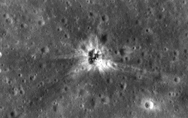
After decades of uncertainty, the Apollo 16 S-IVB impact site on the lunar surface has been identified. S-IVBs were portions of the Saturn V rockets that brought astronauts to the moon. The site was identified in imagery from the high-resolution LROC Narrow Angle Camera aboard NASA's Lunar Reconnaissance Orbiter. Beginning with Apollo 13, the S-IVB rocket stages were deliberately impacted on the lunar surface after they were used. Seismometers placed on the moon by earlier Apollo astronauts measured the energy of these impacts to shed light on the internal lunar structure. Locations of the craters that the boosters left behind were estimated from tracking data collected just prior to the impacts. Earlier in the LRO mission, the Apollo 13, 14, 15 and 17 impact sites were successfully identified, but Apollo 16's remained elusive. In the case of Apollo 16, radio contact with the booster was lost before the impact, so the location was only poorly known. Positive identification of the Apollo 16 S-IVB site took more time than the other four impact craters because the location ended up differing by about 30 km (about 19 miles) from the Apollo-era tracking estimate. (For comparison, the other four S-IVB craters were all within 7 km -- about four miles -- of their estimated locations.) Apollo 16's S-IVB stage is on Mare Insularum, about 160 miles southwest of Copernicus Crater (more precisely: 1.921 degrees north, 335.377 degrees east, minus 1,104 meters elevation). Credit: NASA/Goddard/Arizona State University <b><a href="http://www.nasa.gov/audience/formedia/features/MP_Photo_Guidelines.html" rel="nofollow">NASA image use policy.</a></b> <b><a href="http://www.nasa.gov/centers/goddard/home/index.html" rel="nofollow">NASA Goddard Space Flight Center</a></b> enables NASA’s mission through four scientific endeavors: Earth Science, Heliophysics, Solar System Exploration, and Astrophysics. Goddard plays a leading role in NASA’s accomplishments by contributing compelling scientific knowledge to advance the Agency’s mission. <b>Follow us on <a href="http://twitter.com/NASAGoddardPix" rel="nofollow">Twitter</a></b> <b>Like us on <a href="http://www.facebook.com/pages/Greenbelt-MD/NASA-Goddard/395013845897?ref=tsd" rel="nofollow">Facebook</a></b> <b>Find us on <a href="http://instagrid.me/nasagoddard/?vm=grid" rel="nofollow">Instagram</a></b>
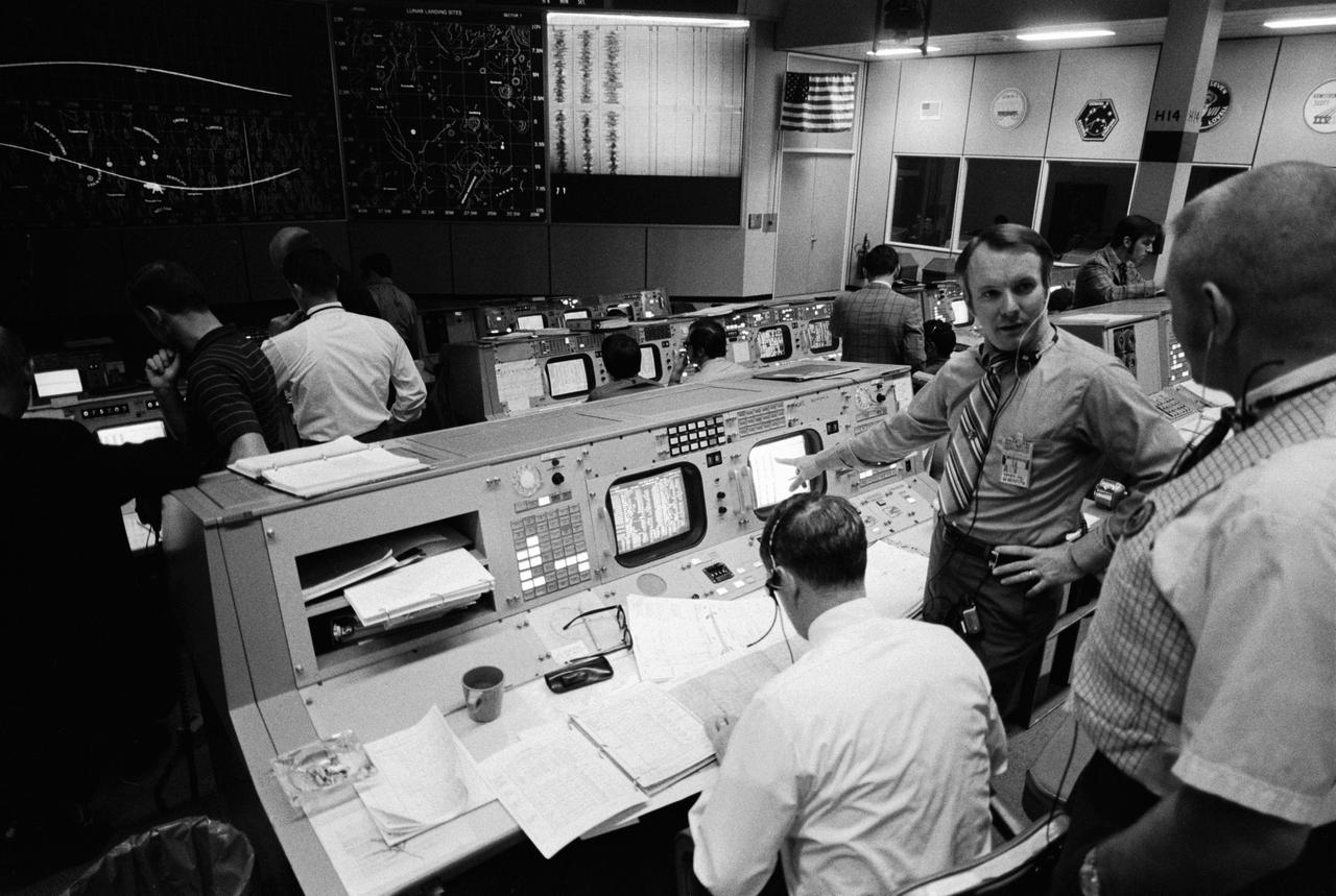
S71-17610 (4 Feb. 1971) --- Partial view of activity in the Mission Operations Control Room in the Mission Control Center at the time the Apollo 14 S-IVB stage impacted on the lunar surface. The flight director's console is in the foreground. Eugene F. Kranz, chief of the MSC Flight Control Division, is in the right foreground. Seated at the console is Glynn S. Lunney, head of the Flight Director Office, Flight Control Division. Facing the camera is Gerald D. Griffin, flight director of the Third (Gold) Team. A seismic reading from the impact can be seen in the center background. The S-IVB impacted on the lunar surface at 1:40:54 a.m. (CST), Feb. 4, 1971, about 90 nautical miles south-southwest of the Apollo 12 passive seismometer. The energy release was comparable to 11 tons of TNT.
This 1968 cutaway drawing illustrates the Saturn IB launch vehicle with its two booster stages, the S-IB and S-IVB. Developed by the Marshall Space Flight Center (MSFC) as an interim vehicle in MSFC's "building block" approach to the Saturn rocket development, the Saturn IB utilized Saturn I technology to further develop and refine the larger boosters and the Apollo spacecraft capabilities required for the marned lunar mission.
This undated cutaway drawing illustrates the Saturn IB launch vehicle with its two booster stages, the S-IB and S-IVB. Developed by the Marshall Space Flight Center (MSFC) as an interim vehicle in MSFC's "building block" approach to the Saturn rocket development, the Saturn IB utilized Saturn I technology to further develop and refine the larger boosters and the Apollo spacecraft capabilities required for the marned lunar missions.
Marshall Space Flight Center (MSFC) workers lower S-IB-200D, a dynamic test version of the Saturn IB launch vehicle's first stage (S-IB stage), into the Center's Dynamic Test Stand on January 12, 1965. Test Laboratory persornel assembled a complete Saturn IB to test the structural soundness of the launch vehicle. Developed by the MSFC as an interim vehicle in MSFC's "building block" approach to Saturn rocket development, the Saturn IB utilized Saturn I technology to further develop and refine large boosters and the Apollo spacecraft capabilities required for the manned lunar missions.
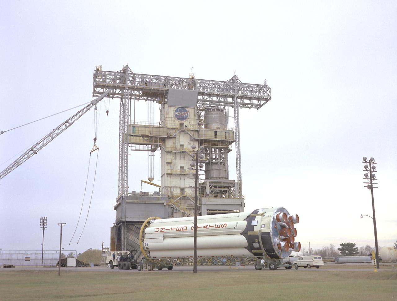
Workmen remove the Saturn IB S-IVB-206, the second flight stage for the Skylab 2 mission, from the vehicle assembly building at the Kennedy Space Center. Designed and developed by the Marshall Space Flight Center and the Douglas Aircraft Company in Sacramento, California, the stage was powered by a single J-2 engine, which produced 200,000 pounds of thrust, later uprated to 230,000 pounds for the Saturn V launch vehicle.
The powerful J-2 engine is prominent in this photograph of a Saturn V Third Stage (S-IVB) resting on a transporter in the Manufacturing Facility at Marshall Space Flight Center in Huntsville, Alabama. The towering 363-foot Saturn V was a multi-stage, multi-engine launch vehicle standing taller than the Statue of Liberty. Altogether, the Saturn V engines produced as much power as 85 Hoover Dams.
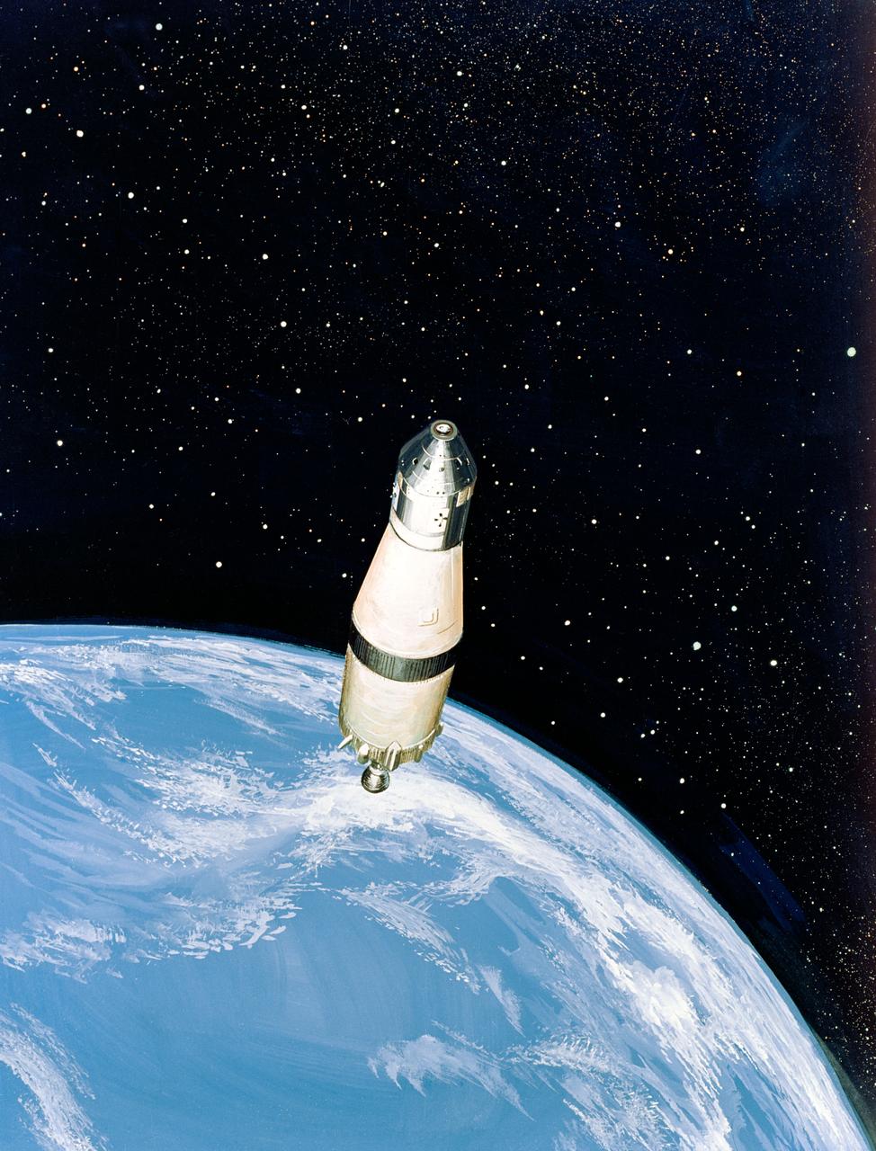
S68-51304 (December 1968) --- North American Rockwell artist's concept illustrating a phase of the scheduled Apollo 8 lunar orbit mission. Here, the Apollo 8 spacecraft Command and Service Modules (CSM), still attached to the Saturn V (S-IVB) third stage, heads for the moon at a speed of about 24,300 miles per hour. The trajectory, computed from the Saturn V's third stage instrumentation unit, provides a "free return" to Earth around the moon.

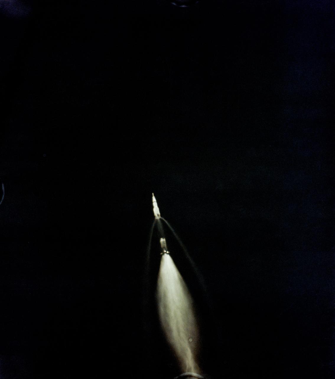
This photograph shows an early moment of the first test flight of the Saturn V vehicle for the Apollo 4 mission, photographed by a ground tracking camera, on the morning of November 9, 1967. This mission was the first launch of the Saturn V launch vehicle. Objectives of the unmarned Apollo 4 test flight were to obtain flight information on launch vehicle and spacecraft structural integrity and compatibility, flight loads, stage separation, and subsystems operation including testing of restart of the S-IVB stage, and to evaluate the Apollo command module heat shield.
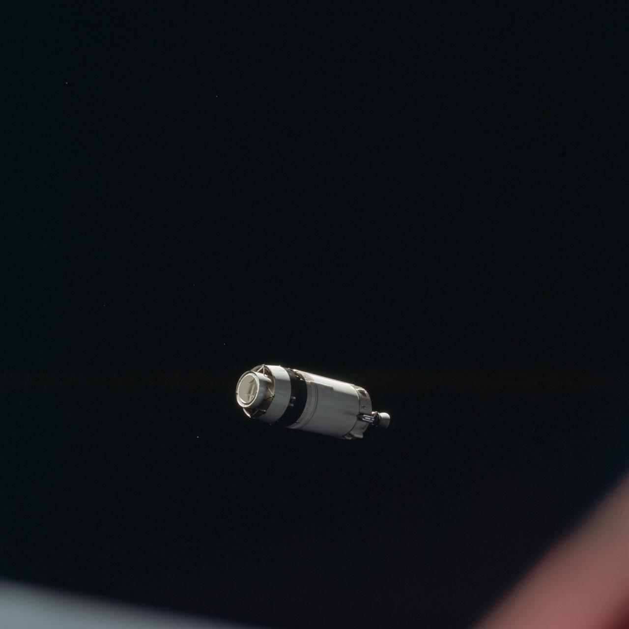
AS08-16-2584 (21 Dec. 1968) --- This is a photograph taken from the Apollo 8 spacecraft looking back at the Saturn V third (S-IVB) stage from which the spacecraft had just separated following trans-lunar injection. Attached to the S-IVB is the Lunar Module Test Article (LTA) which simulated the mass of a Lunar Module (LM) on the Apollo 8 lunar orbit mission. The 29-feet panels of the Spacecraft LM Adapter which enclosed the LTA during launch have already been jettisoned and are out of view. Sunlight reflected from small particles shows the "firefly" phenomenon which was reported by astronaut John H. Glenn Jr. during the first Earth-orbital flight, Mercury-Atlas 6 (MA-6) of the Mercury Program.
AS08-16-2583 (21 Dec. 1968) --- This is a photograph taken from the Apollo 8 spacecraft looking back at the Saturn V third (S-IVB) stage from which the spacecraft had just separated following trans-lunar injection. Attached to the S-IVB is the Lunar Module Test Article (LTA) which simulated the mass of a Lunar Module (LM) on the Apollo 8 lunar orbit mission. The 29-feet panels of the Spacecraft LM Adapter which enclosed the LTA during launch have already been jettisoned and are out of view. Sunlight reflected from small particles shows the "firefly" phenomenon which was reported by astronaut John H. Glenn Jr. during the first Earth-orbital flight, Mercury-Atlas 6 (MA-6) of the Mercury Program.
This September 1967 photograph shows workmen removing a mockup of the Saturn V S-IVB stage that housed the Skylab Orbital Workshop (OWS) from the Marshall Space Flight Center (MSFC), building 4755. The mockup was shipped to McDornell Douglas in Huntington, California for design modifications. NASA used the mockup as an engineering design tool to plan structures, equipment, and experiments for Skylab, an orbiting space laboratory. The MSFC had program management responsibility for the development of Skylab hardware and experiments, including the OWS.
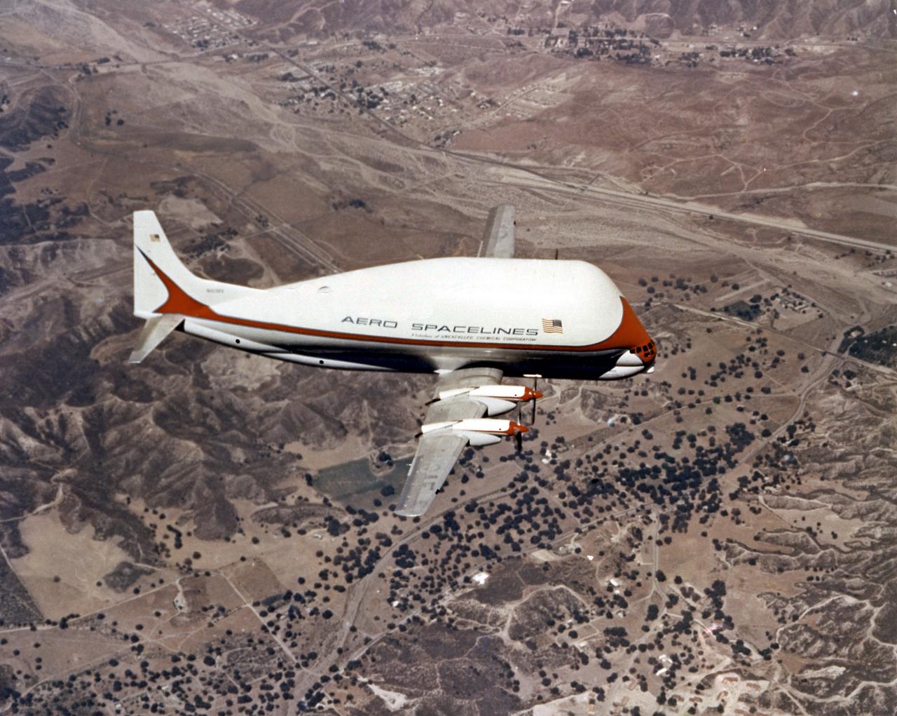
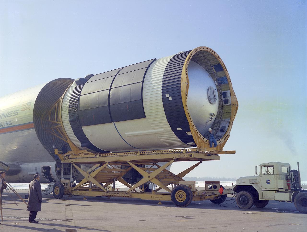
Super Guppy, bigger sister of the aptly named Pregnant Guppy, was the only airplane in the world capable of carrying a complete S-IVB stage. This aircraft was built by John M. Conroy of Aero Spaceliners, Incorporated, who started with the fuselages of a surplus Boeing C-97 Stratocruiser, ballooned out the upper decks enormously, and hinged the front sections so that they could be folded back 110 degrees. The Super Guppy flew smoothly at a 250-mph cruising speed, and its cargo deck provided a 25-foot clear diameter.
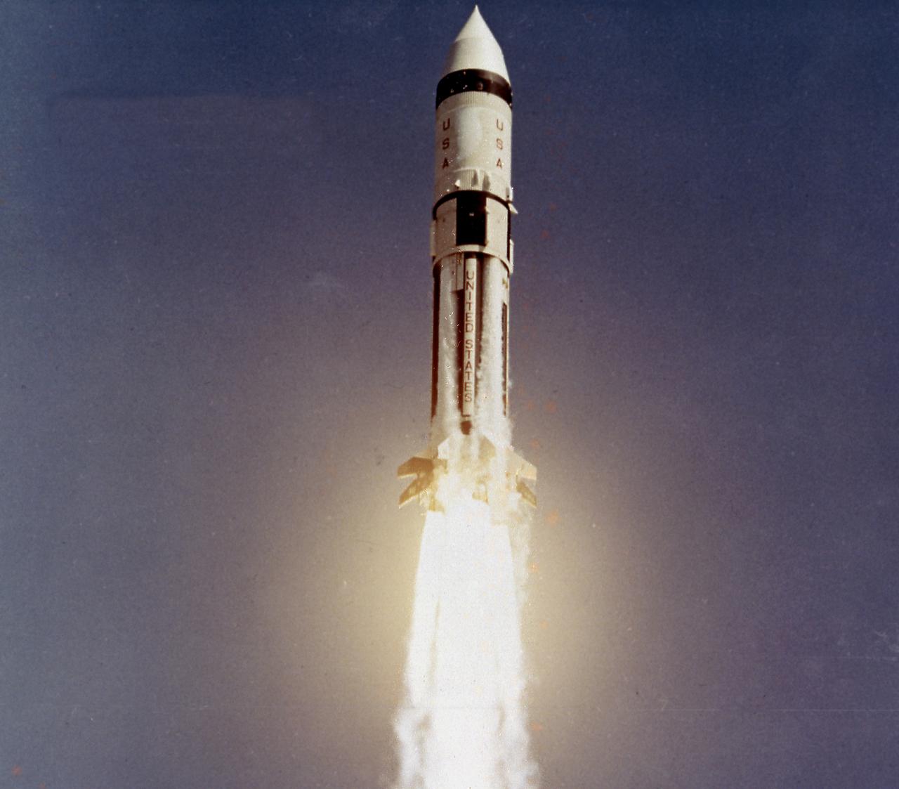
AS-203, the third Saturn IB launch vehicle developed by the Marshall Space Flight Center, lifts off from Cape Canaveral, Florida , July 5, 1966. Primary mission objectives included evaluation of the S-IVB stage's hydrogen venting and engine restart capabilities in an orbital environment. In all, nine Saturn IB flights were made, ending with the Apollo-Soyuz Test Project (ASTP) in July 1975.
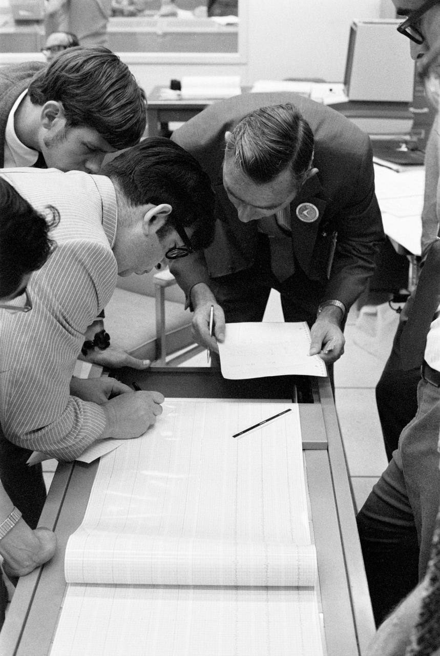
The seismometer reading from the impact made by the Apollo 15 Saturn S-IVB stage when it struck the lunar surface is studied by scientists in the Mission Control Center. Dr. Gary Latham (dark suit, wearing lapel button) of Columbia University is responsible for the design and experiment data analysis of the Passive Seismic Experiment of the Apollo Lunar Surface Experiment Package (ALSEP). The man on the left, writing, is Nafi Toksos of the Massachusetts Institute of Technology. Looking on at upper left is Dave Lamneline, also with Columbia.
Workers at the Marshall Space Flight Center (MSFC) move a facility test version of the Saturn IB launch vehicle's second stage, the S-IVB, to the J-2 test stand on February 10, 1965. Also known as a "battleship" because of its heavy, rugged construction, the non-flight, stainless-steel model was used to check out testing facilities at MSFC.
Workers at the Marshall Space Flight Center (MSFC) move a facility test version of the Saturn IB launch vehicle's second stage, the S-IVB, to the J-2 test stand on February 10, 1965. Also known as a "battleship" because of its heavy, rugged construction, the non-flight, stainless-steel model was used to check out testing facilities at MSFC.
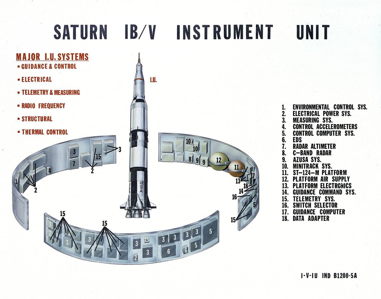
This undated chart provides a description of the Saturn IB and Saturn V's Instrument Unit (IU) and its major components. Designed by NASA at the Marshall Space Flight Center (MSFC), the Instrument Unit, sandwiched between the S-IVB stage and the Apollo spacecraft, served as the Saturn's "nerve center" providing guidance and control, command and sequence of vehicle functions, telemetry, and environmental control.

AS-204, the fourth Saturn IB launch vehicle, developed by the Marshall Space Flight Center (MSFC), awaits its January 22, 1968 liftoff from Cape Canaveral, Florida for the unmarned Apollo 5 mission. Primary mission objectives included the verification of the Apollo Lunar Module's (LM) ascent and descent propulsion systems and an evaluation of the S-IVB stage instrument unit performance. In all, nine Saturn IB flights were made, ending with the Apollo-Soyuz Test Project in July 1975.
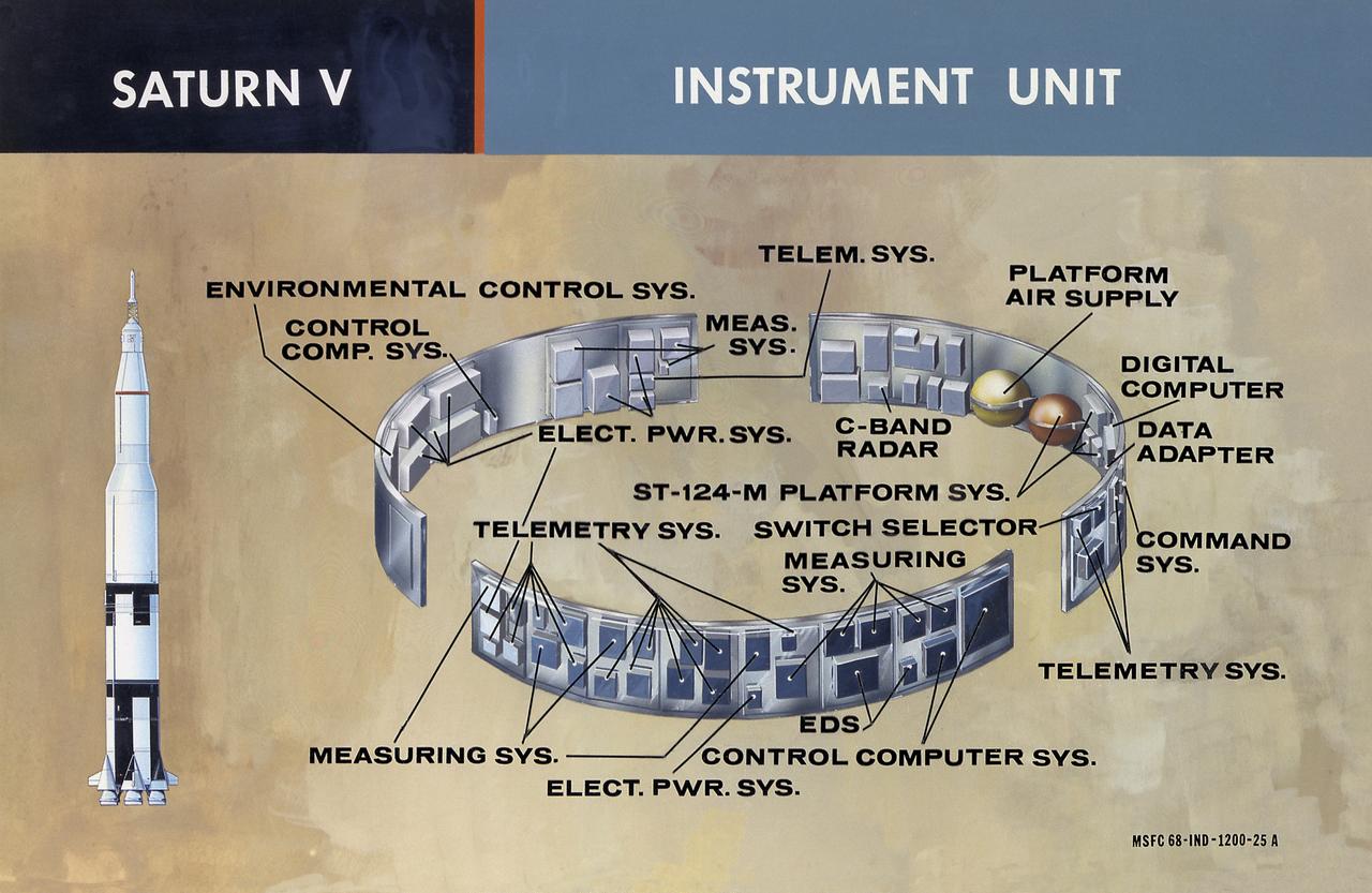
This illustration shows the major components of the instrument unit (IU). Developed and manufactured by International Business Machines, the IU is 3 feet high and 21 feet in diameter and mounted atop an S-IVB, between the third stage and the Apollo spacecraft. It contained the computers, all guidance, control, and sequencing equipment to keep the the launch vehicle properly functioning and on its course. The IU was essentially the same in both the Saturn IB and the Saturn V.
A facility test version of the S-IVB, the second stage of the Saturn IB launch vehicle, sits in the Marshall Space Flight Center (MSFC) J-2 test stand on February 10, 1965. Also known as a "battleship" because of its heavy, rugged construction, the non-flight, stainless-steel model was used to check out testing facilities at MSFC.

AS04-01-410 (9 Nov. 1967) --- Coastal Brazil, Atlantic Ocean, West Africa, Sahara, Antarctica, looking west, as photographed from the Apollo 4 (Spacecraft 017/Saturn 501) unmanned, Earth-orbital space mission. This picture was taken when the Spacecraft 017 and Saturn S-IVB (third) stage were orbiting Earth at an altitude of 9,745 nautical miles.
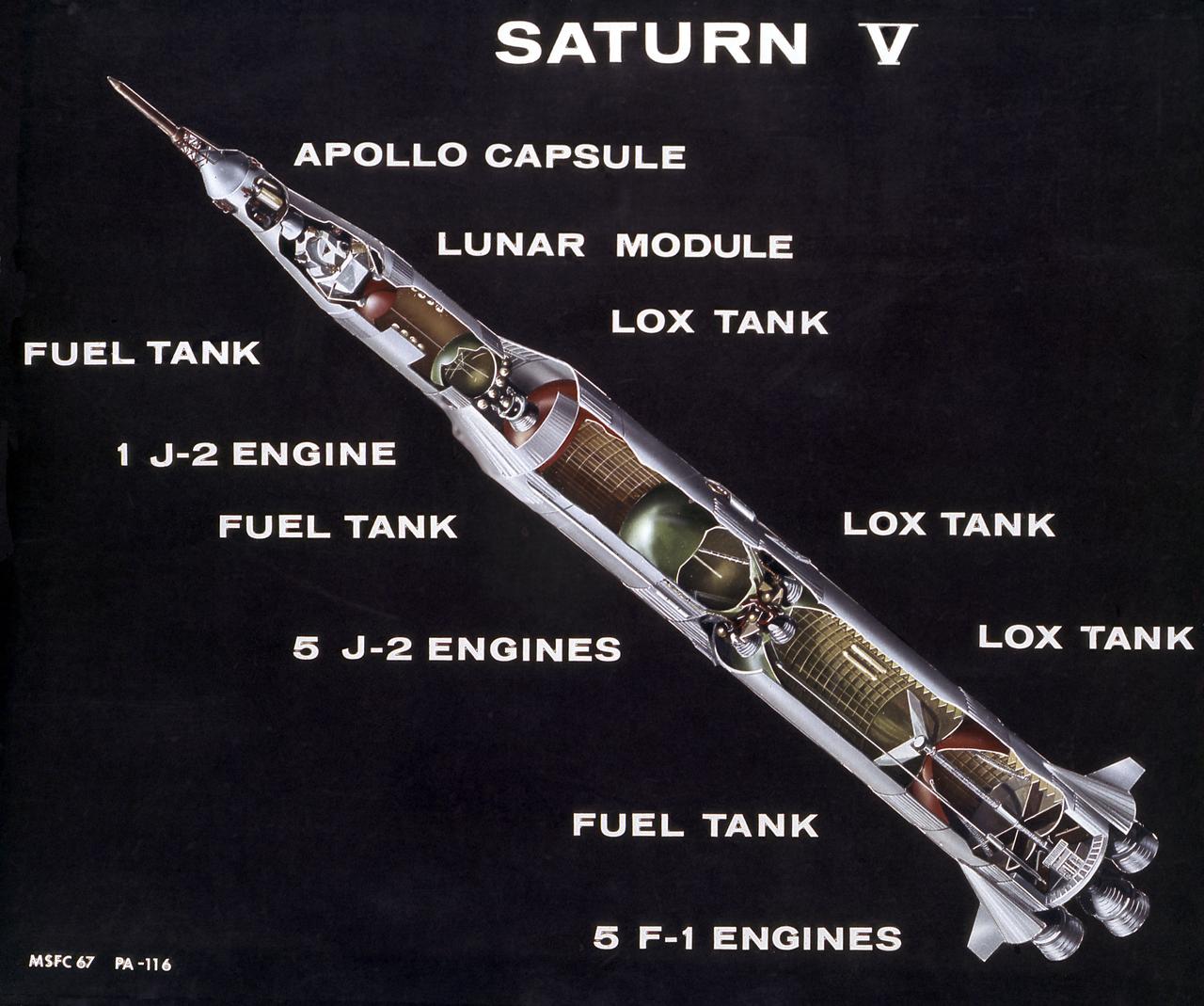
This is a cutaway illustration of the Saturn V launch vehicle with callouts of the major components. The Saturn V is the largest and most powerful launch vehicle developed in the United States. It was a three stage rocket, 363 feet in height, used for sending American astronauts to the moon and for placing the Skylab in Earth orbit. The Saturn V was designed to perform Earth orbital missions through the use of the first two stages, while all three stages were used for lunar expeditions. The S-IC stage (first stage) was powered by five F- engines, which burned kerosene and liquid oxygen to produce more than 7,500,000 pounds of thrust. The S-II (second) stage was powered by five J-2 engines, that burned liquid hydrogen and liquid oxygen and produced 1,150,000 pounds thrust. The S-IVB (third) stage used one J-2 engine, producing 230,000 pounds of thrust, with a re-start capability. The Marshall Space Flight Center and its contractors designed, developed, and assembled the Saturn V launch vehicle stages.
S69-39958 (16 July 1969) --- A 70mm Airborne Lightweight Optical Tracking System (ALOTS) camera, mounted in a pod on a cargo door of a U.S. Air Force EC-135N aircraft, photographed this event in the early moments of the Apollo 11 launch. The mated Apollo spacecraft and Saturn V second (S-II) and third (S-IVB) stages pull away from the expended first (S-1C) stage. Separation occurred at an altitude of about 38 miles, some 55 miles downrange from Cape Kennedy. The aircraft's pod is 20 feet long and 5 feet in diameter. The crew of the Apollo 11 lunar landing mission are astronauts Neil A. Armstrong, Michael Collins, and Edwin E. Aldrin Jr.
This photograph was taken during the final assembly operation of the Saturn V launch vehicle for the Apollo 4 (SA 501) mission. The instrument unit (IU) was mated atop the S-IC/S-II assembly in the Vehicle Assembly Building high bay at the Kennedy Space Center. The Apollo 4 mission was the first launch of the Saturn V launch vehicle. Objectives of the unmanned Apollo 4 test flight were to obtain flight information on launch vehicle and spacecraft structural integrity and compatibility, flight loads, stage separation, and subsystems operation including testing of restart of the S-IVB stage, and to evaluate the Apollo command module heat shield. The Apollo 4 was launched on November 9, 1967 from KSC.
This photograph was taken during the final assembly operation of the Saturn V launch vehicle for the Apollo 4 (SA 501) mission. The instrument unit (IU) was hoisted to be mated to the S-IC/S-II assembly in the Vehicle Assembly Building high bay at the Kennedy Space Center. The Apollo 4 mission was the first launch of the Saturn V launch vehicle. Objectives of the unmanned Apollo 4 test flight were to obtain flight information on launch vehicle and spacecraft structural integrity and compatibility, flight loads, stage separation, and subsystems operation including testing of restart of the S-IVB stage, and to evaluate the Apollo command module heat shield. The Apollo 4 was launched on November 9, 1967 from KSC.
This is a view of the the first test flight of the Saturn V vehicle (SA-501) at the Kennedy Space Center (KSC) launch complex 39A, awaiting the scheduled launch on November 9, 1967. Designated as Apollo 4, this mission was the first launch of the Saturn V launch vehicle. Objectives of the unmanned Apollo 4 test flight were to obtain flight information on launch vehicle and spacecraft structural integrity and compatibility, flight loads, stage separation, and subsystems operation including testing of restart of the S-IVB stage, and to evaluate the Apollo command module heat shield.
Marshall Space Flight Center (MSFC) workers hoist a dynamic test version of the S-IVB stage, the Saturn IB launch vehicle's second stage, into the Center's Dynamic Test Stand on January 18, 1965. MSFC Test Laboratory persornel assembled a complete Saturn IB to test the launch vehicle's structural soundness. Developed by the MSFC as an interim vehicle in MSFC's "building block" approach to the Saturn rocket development, the Saturn IB utilized Saturn I technology to further develop and refine the larger boosters and the Apollo spacecraft capabilities required for the manned lunar missions.
This picture shows the Saturn V vehicle (AS-501), for the Apollo 4 mission on the Crawler Transporter Vehicle. It was rolled out from the Vehicle Assembly Building and slowly (1 mph) moved to the launch pad at the Kennedy Space Center (KSC). The Apollo 4 mission was the first launch of the Saturn V launch vehicle. Objectives of the unmanned Apollo 4 test flight were to obtain flight information on launch vehicle and spacecraft structural integrity and compatibility, flight loads, stage separation, and subsystems operation including testing of restart of the S-IVB stage, and to evaluate the Apollo command module heat shield. The Apollo 4 was launched on November 9, 1967 from KSC.

S68-19459 (22 Jan. 1968) --- The Apollo 5 (LM-1/Saturn 204) unmanned space mission was launched from the Kennedy Space Center's Launch Complex 37 at 5:48:09 p.m. (EST), Jan. 22, 1968. The Lunar Module-1 payload was boosted into Earth orbit by a launch vehicle composed of a Saturn IB first stage and a Saturn S-IVB second stage. The Apollo lunar module's first flight test was called a complete success. Ascent and descent propulsion systems and the ability to abort a lunar landing and return to orbit were demonstrated.

This photograph depicts the Saturn V vehicle (SA-501) for the Apollo 4 mission in the Vehicle Assembly Building (VAB) at the Kennedy Space Center (KSC). After the completion of the assembly operation, the work platform was retracted and the vehicle was readied to rollout from the VAB to the launch pad. The Apollo 4 mission was the first launch of the Saturn V launch vehicle. Objectives of the unmanned Apollo 4 test flight were to obtain flight information on launch vehicle and spacecraft structural integrity and compatibility, flight loads, stage separation, and subsystems operation including testing of restart of the S-IVB stage, and to evaluate the Apollo command module heat shield. The Apollo 4 was launched on November 9, 1967 from KSC.

S68-19460 (22 Jan. 1968) --- The Apollo 5 (LM-1/Saturn 204) unmanned space mission was launched from the Kennedy Space Center's Launch Complex 37 at 5:48:09 p.m. (EST), Jan. 22, 1968. The Lunar Module-1 payload was boosted into Earth orbit by a launch vehicle composed of a Saturn IB first stage and a Saturn S-IVB second stage. The Apollo lunar module's first flight test was called a complete success. Ascent and descent propulsion systems and the ability to abort a lunar landing and return to orbit were demonstrated.
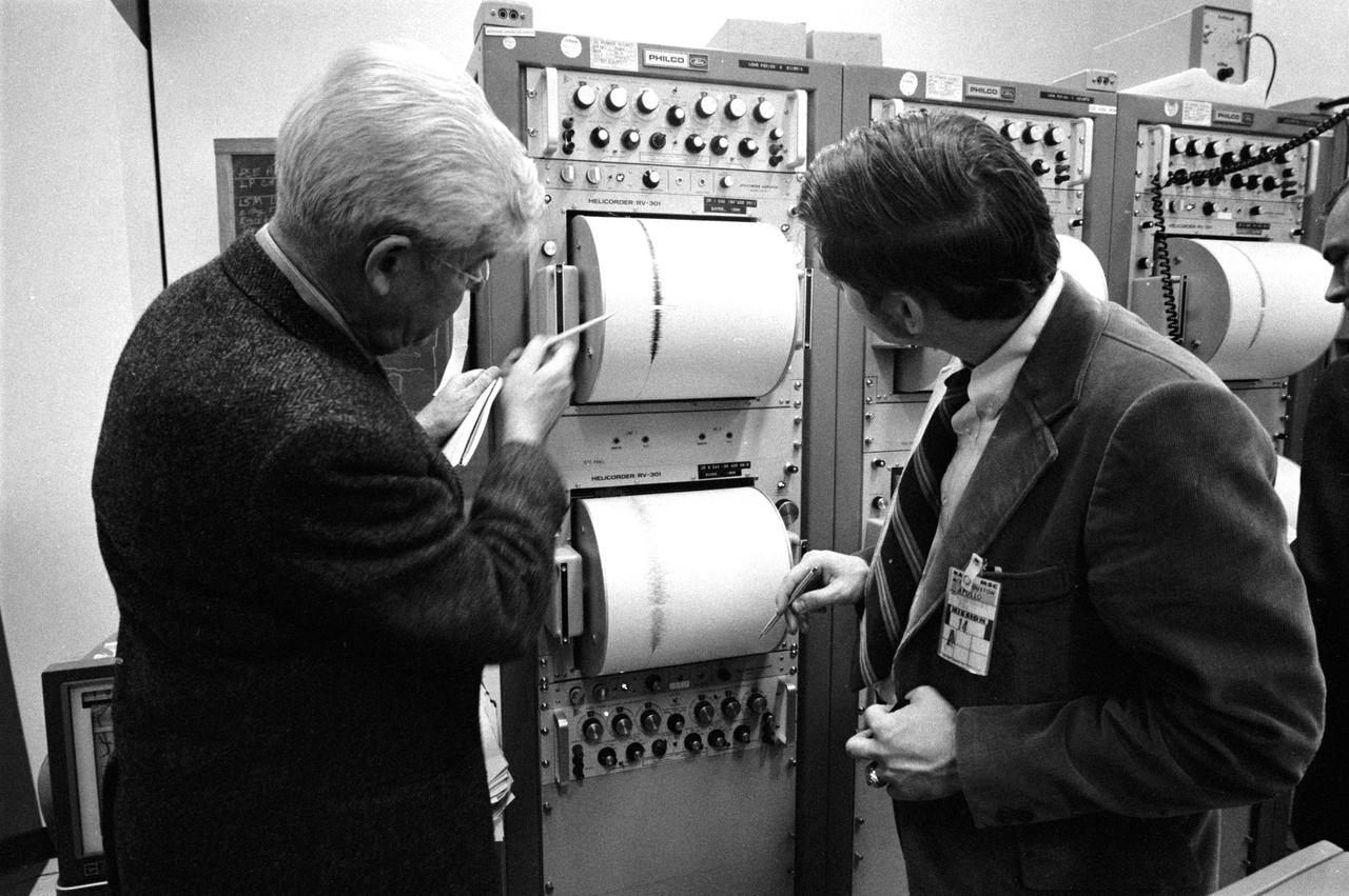
S71-17609 (4 Feb. 1971) --- These two individuals are examining a seismic reading in the Mission Control Center's ALSEP Room during the Apollo 14 S-IVB impact on the moon. Dr. Maurice Ewing (left) is the director of the Lamont-Doherty Geological Observatory at Columbia University. David Lammlein, a Columbia graduate student, is on the right. The Apollo 14 Saturn IVB stage impacted on the lunar surface at 1:40:54 a.m. (CST), Feb. 4, 1971, about 90 nautical miles south-southwest of the Apollo 12 passive seismometer. The energy release was comparable to 11 tons of TNT. Dr. Gary Latham of the Lamont-Doherty Geological Observatory is the principal investigator for the Passive Seismic Experiment, a component of the Apollo Lunar Surface Experiments Package.
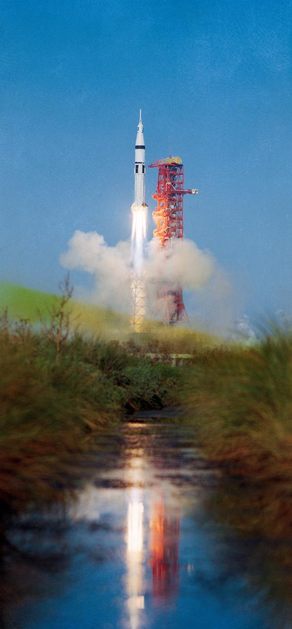
S73-37285 (16 Nov. 1973) --- The Skylab 4/Saturn 1B space vehicle is launched from Pad B, Launch Complex 39, Kennedy Space Center, Florida, at 9:01:23 a.m. (EST), Friday, Nov. 16, 1973. Skylab 4 is the third and last of three scheduled manned Skylab missions. Aboard the Skylab 4 Command/Service Module were astronauts Gerald P. Carr, Edward G. Gibson and William R. Pogue. In addition to the CSM and its launch escape system, the Skylab 4 space vehicle consisted of the Saturn 1B first (S-1B) stage and the Saturn 1B second (S-IVB) stage. (The Skylab 1/Saturn V unmanned space vehicle with the space station payload was launched from Pad A on May 14, 1973). Photo credit: NASA

S73-32568 (20 July 1973) --- Floodlights illuminate this nighttime view of the Skylab 3/Saturn 1B space vehicle at Pad B, Launch Complex 39, Kennedy Space Center, Florida, during prelaunch preparations. The reflection is the water adds to the scene. In addition to the Command/Service Module and its launch escapte system, the Skylab 3 space vehicle consists of the Saturn 1B first (S-1B) stage and the Saturn 1B second (S-IVB) stage. The crew for the scheduled 59-day Skylab 3 mission in Earth orbit will be astronauts Alan L. Bean, Owen K. Garriott and Jack R. Lousma. Skylab 3 was launched on July 28, 1973. Photo credit: NASA
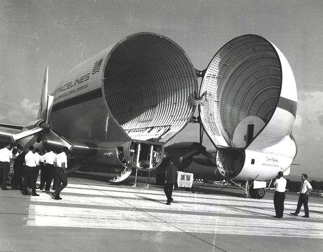
The Super Guppy is shown at the Redstone Airstrip. NASA used the aircraft to transport the S-IVB upper stage used on the Saturn IB and Saturn V launch vehicles between manufacturing facilities on the West coast, and testing and launch facilities in the Southeast. This aircraft was built by John M. Conroy of Aero Spaceliners, Incorporated, who started with the fuselages of a surplus Boeing C-97 Stratocruiser, ballooned out the upper decks enormously, and hinged the front sections so that they could be folded back 110 degrees. The Super Guppy flew smoothly at a 250-mph cruising speed, and its cargo deck provided a 25-foot clear diameter.

AS04-01-580 (9 Nov. 1967) --- Earth as viewed from 10,000 miles. In 1969, the Apollo 4 (Spacecraft 017/Saturn 501) unmanned test flight made a great ellipse around Earth as a test of the translunar motors and of the high speed entry required of a manned flight returning from the moon. A 70mm camera was programmed to look out a window toward Earth, and take a series of photographs from "high apogee". Coastal Brazil, Atlantic Ocean, West Africa, Antarctica, looking west. This photograph was made when the Apollo 4 spacecraft, still attached to the S-IVB (third) stage, was orbiting Earth at an altitude of 9,544 miles.
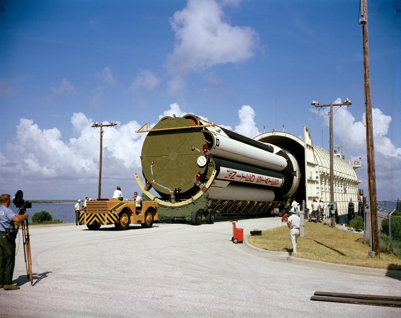
S66-50152 (1966) --- A stage of the uprated Saturn 1 launch vehicle unloaded from NASA barge Promise after arrival at Cape Kennedy. Launch vehicle for Apollo/Saturn 204 mission.
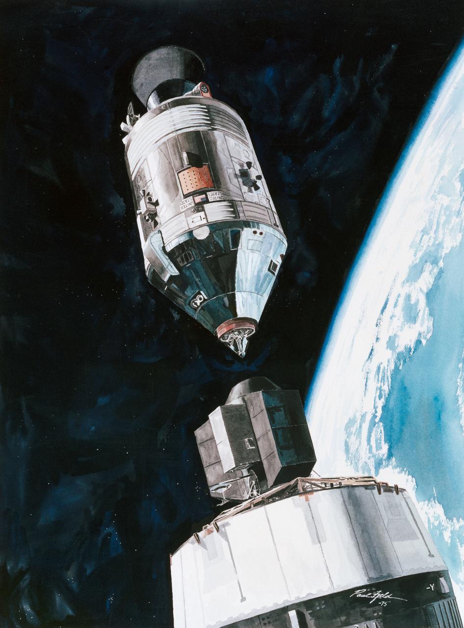
S75-28512 (July 1975) --- An artist?s concept depicting a scene in Earth orbit during the Apollo transposition and docking maneuvers of the Apollo-Soyuz Test Project mission. The Command/Service Module is moving into position to dock with the Docking Module. Following the docking the DM will be extracted from the expended Saturn IVB stage. The Docking Module is designed to link the American Apollo spacecraft with the Soviet Soyuz spacecraft. This scene will take place some one hour and twenty-three minutes after the Apollo-Saturn 1B liftoff from the Kennedy Space Center on July 15, 1975. The Soyuz launch at 7:20 a.m. (CDT) from the Baikonur, Kazakhstan launch pad will precede the Apollo liftoff by seven and one-half hours. The artwork is by Paul Fjeld.