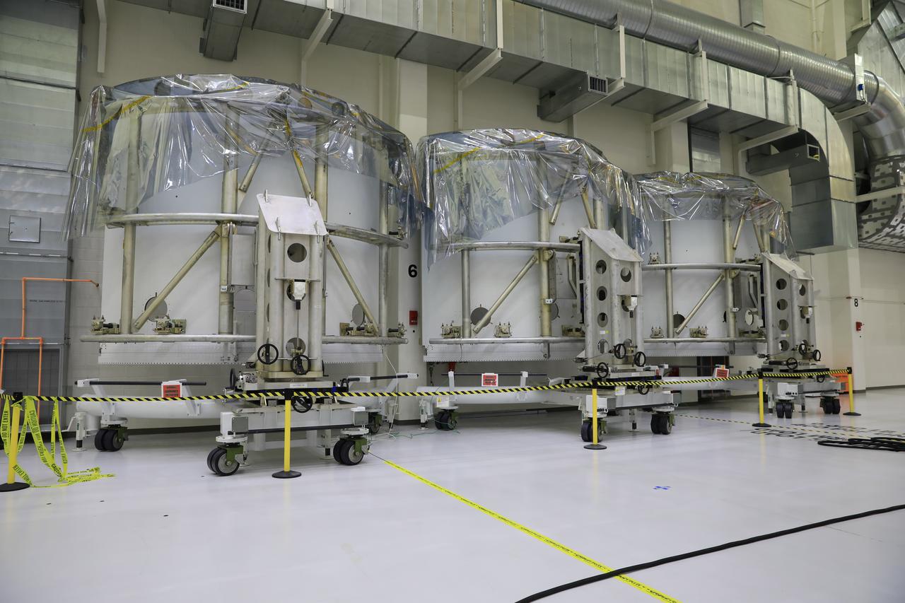
Pictured inside the Neil Armstrong Operations and Checkout Building high bay at NASA’s Kennedy Space Center in Florida on Aug. 6, 2020, are the three Spacecraft Adapter Jettison fairing panels that will protect Orion's service module from the environment around it, whether it's heat, wind or acoustics during the ascent. Unlike conventional rocket fairings, Orion's are designed to support half of the weight of the crew module and launch abort system during launch and ascent, which will maximize the size and capability of the spacecraft that can be delivered to orbit. Orion will fly on the agency’s Artemis I mission – the first in a series of increasingly complex missions to the Moon that will ultimately lead to the exploration of Mars.
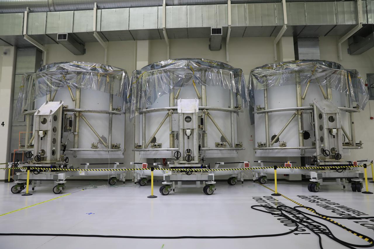
Pictured inside the Neil Armstrong Operations and Checkout Building high bay at NASA’s Kennedy Space Center in Florida on Aug. 6, 2020, are the three Spacecraft Adapter Jettison fairing panels that will protect Orion's service module from the environment around it, whether it's heat, wind or acoustics during the ascent. Unlike conventional rocket fairings, Orion's are designed to support half of the weight of the crew module and launch abort system during launch and ascent, which will maximize the size and capability of the spacecraft that can be delivered to orbit. Orion will fly on the agency’s Artemis I mission – the first in a series of increasingly complex missions to the Moon that will ultimately lead to the exploration of Mars.
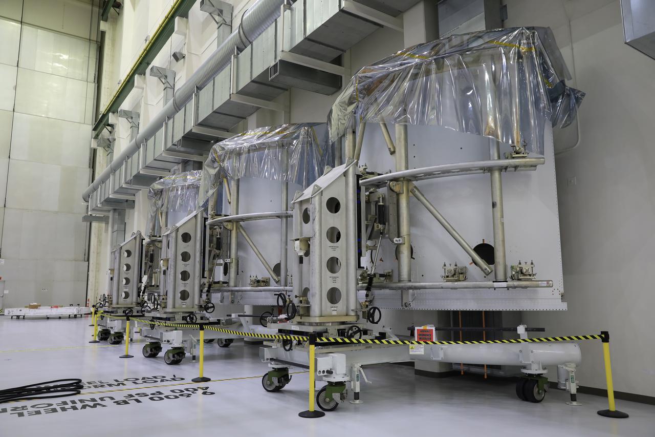
Pictured inside the Neil Armstrong Operations and Checkout Building high bay at NASA’s Kennedy Space Center in Florida on Aug. 6, 2020, are the three Spacecraft Adapter Jettison fairing panels that will protect Orion's service module from the environment around it, whether it's heat, wind or acoustics during the ascent. Unlike conventional rocket fairings, Orion's are designed to support half of the weight of the crew module and launch abort system during launch and ascent, which will maximize the size and capability of the spacecraft that can be delivered to orbit. Orion will fly on the agency’s Artemis I mission – the first in a series of increasingly complex missions to the Moon that will ultimately lead to the exploration of Mars.
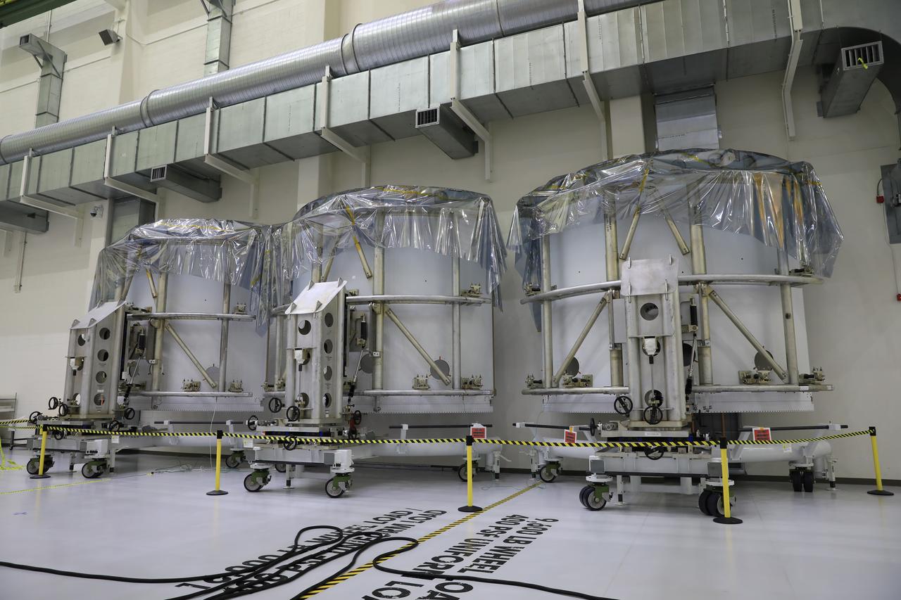
Pictured inside the Neil Armstrong Operations and Checkout Building high bay at NASA’s Kennedy Space Center in Florida on Aug. 6, 2020, are the three Spacecraft Adapter Jettison fairing panels that will protect Orion's service module from the environment around it, whether it's heat, wind or acoustics during the ascent. Unlike conventional rocket fairings, Orion's are designed to support half of the weight of the crew module and launch abort system during launch and ascent, which will maximize the size and capability of the spacecraft that can be delivered to orbit. Orion will fly on the agency’s Artemis I mission – the first in a series of increasingly complex missions to the Moon that will ultimately lead to the exploration of Mars.
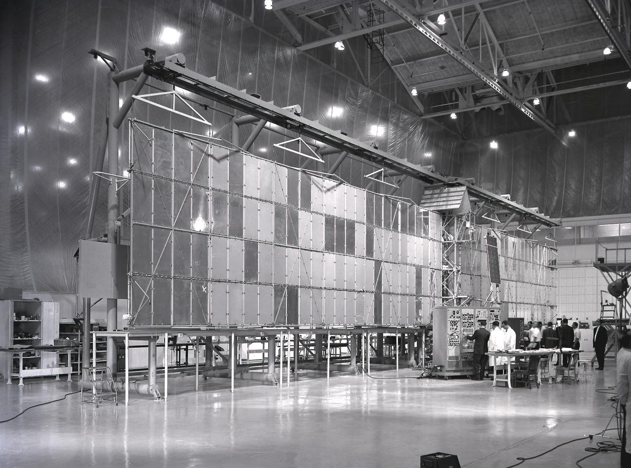
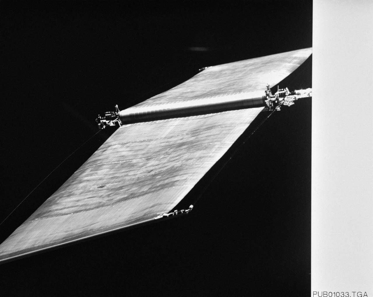
Fairchild technicians check out the extended Pegasus meteoroid detection surface. The Pegasus was developed by Fairchild Stratos Corporation, Hagerstown, Maryland, for NASA through the Marshall Space Flight Center. Three Pegasus satellites were flown aboard Saturn I SA-8, SA-9, and SA-10 missions. After being placed into orbit around the Earth, the satellite unfolded a series of giant panels to form a pair of wings measuring 96 feet across. The purpose of the satellite was to electronically record the size and frequency of particles in space, and compare the performance of protected and unprotected solar cells as important new preliminaries to a marned flight to the Moon.
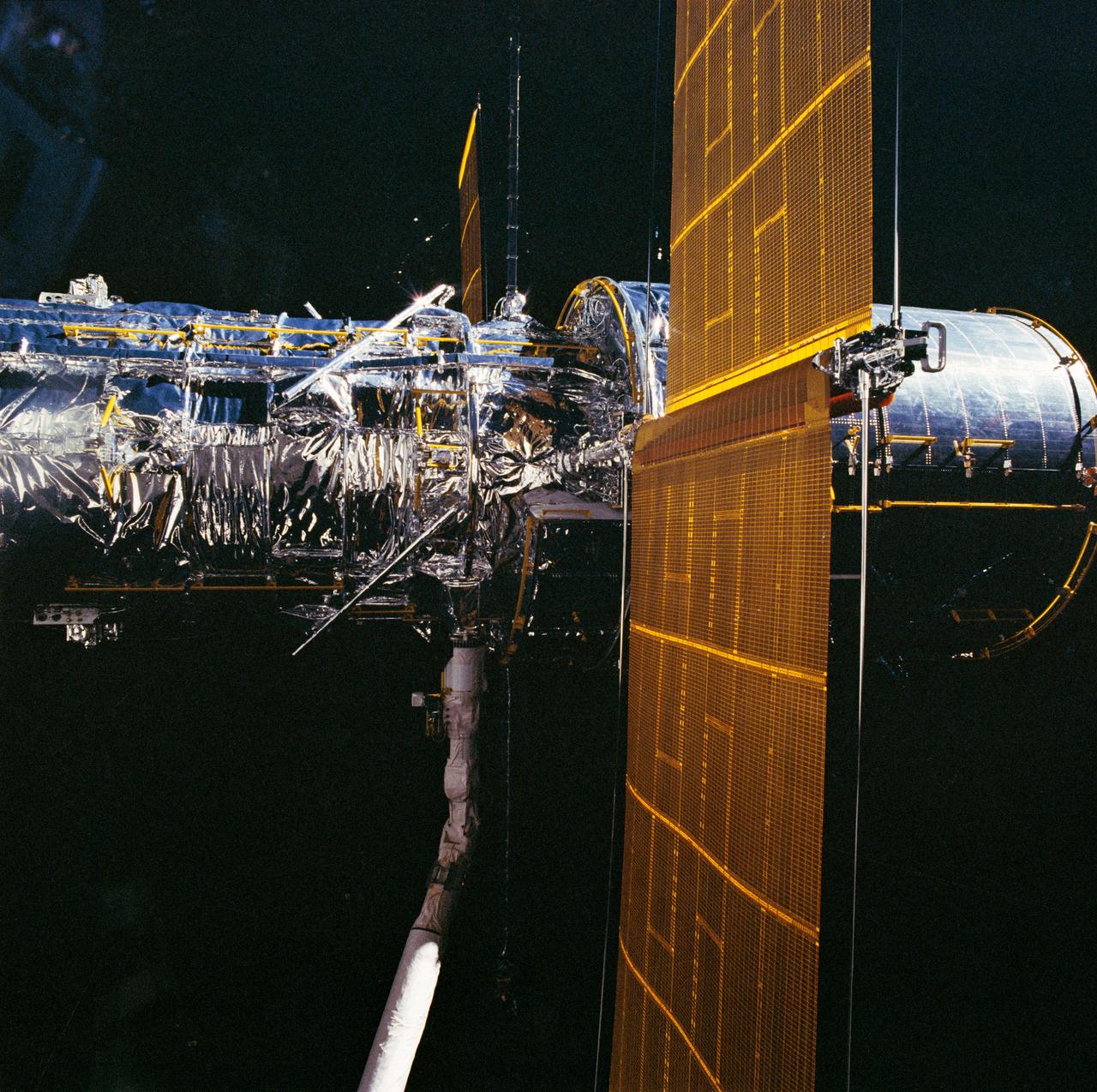
During STS-31, the Hubble Space Telescope (HST), grappled by the remote manipulator system (RMS) end effector, is held against the blackness of space. The two solar array (SA) wings (large gold panels) are fully extended with bistem cassette and secondary deployment mechanism (SDM) handle clearly visible. The two deployed high gain antennae (HGA) masts are parallel to the SA panels. RMS end effector is positioned on the starboard fixture during the predeployment checkout operations above Discovery's, Orbiter Vehicle (OV) 103's, payload bay (PLB).
The Hubble Space Telescope (HST), grappled by Discovery's, Orbiter Vehicle (OV) 103's, remote manipulator system (RMS), is held in a pre-deployment position. During STS-31 checkout procedures, the solar array (SA) panels and the high gain antennae (HGA) will be deployed. The starboard SA (center) and the two HGA are stowed along side the Support System Module (SSM) forward shell. The sun highlights HST against the blackness of space.
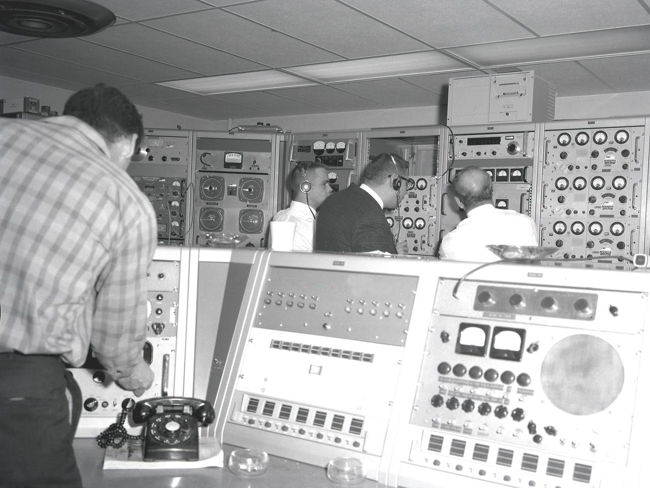
Activities at Green Mountain Tracking Station, Alabama, during lift-off of the Saturn I, SA-9 mission, showing the overall view of instrument panels used in tracking the Pegasus, meteoroid-detection satellite. The satellite was used to obtain data on frequency and penetration of the potentially hazardous micrometeoroids in low Earth orbits and to relay the information back to Earth.
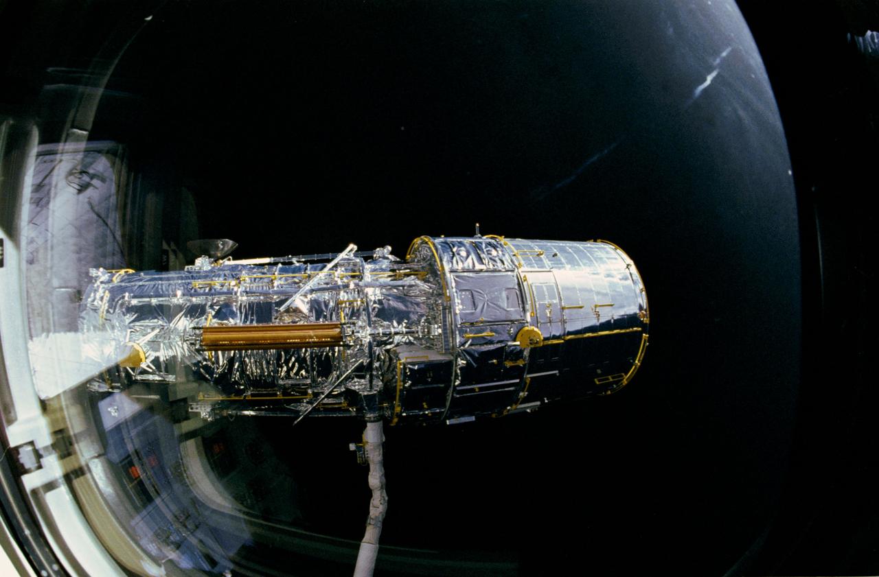
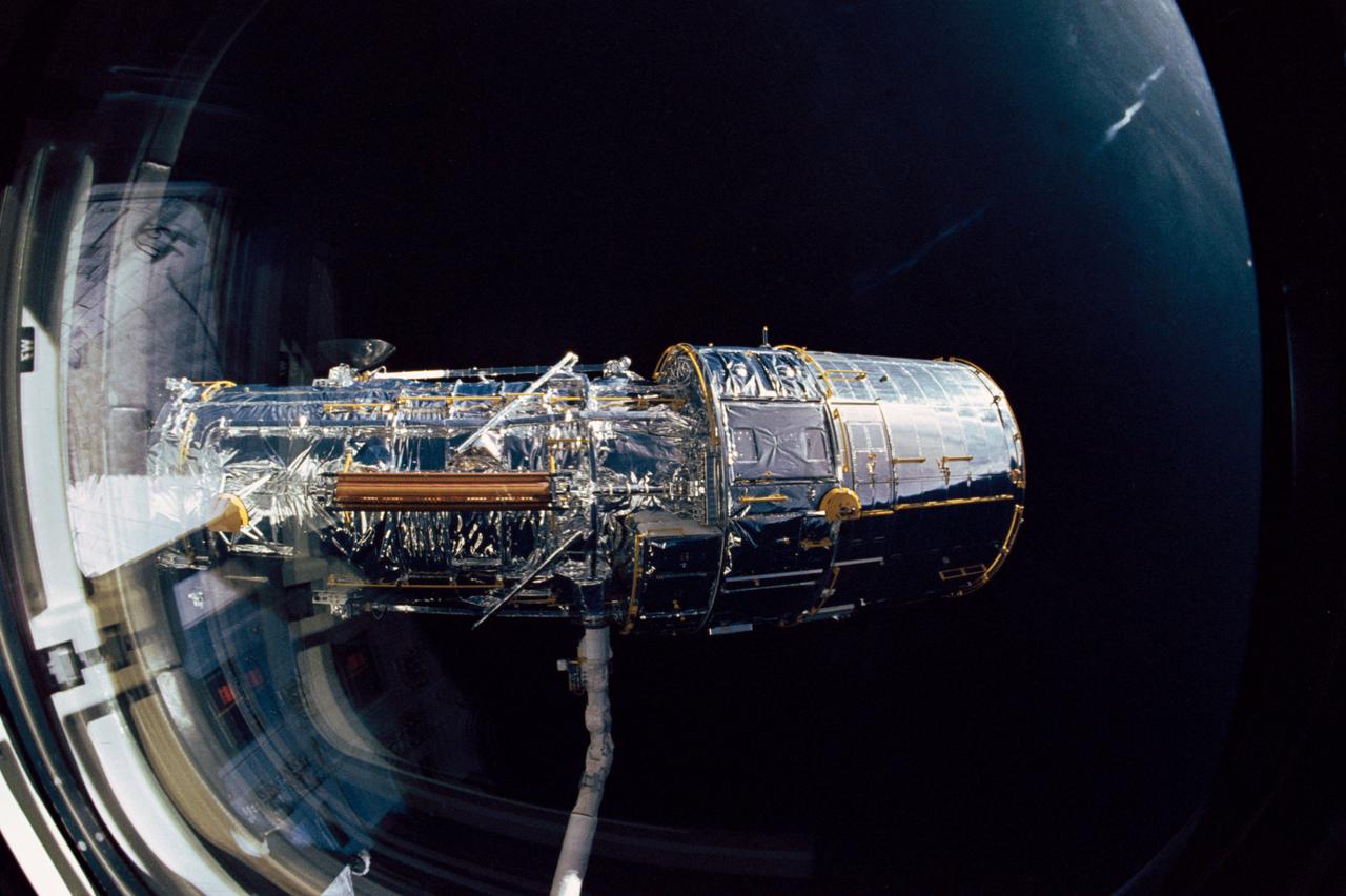
During STS-31 checkout, the Hubble Space Telescope (HST) is held in a pre-deployment position by Discovery's, Orbiter Vehicle (OV) 103's, remote manipulator system (RMS). The view, taken from the crew cabin overhead window W7, shows the starboard solar array (SA) panel (center) and two high gain antennae (HGA) (on either side) stowed along side the Support System Module (SSM) forward shell. The sun highlights HST against the blackness of space.
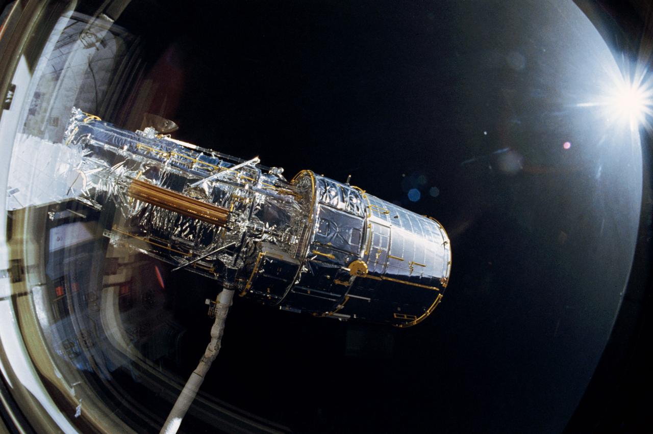
The Hubble Space Telescope (HST), grappled by Discovery's, Orbiter Vehicle (OV) 103's, remote manipulator system (RMS), is oriented in a 90 degree pitch position during STS-31 pre-deployment checkout procedures. The solar array (SA) panel (center) and high gain antennae (HGA) (on either side) are stowed along the Support System Module (SSM) forward shell prior to deployment. The sun highlights HST against the blackness of space.
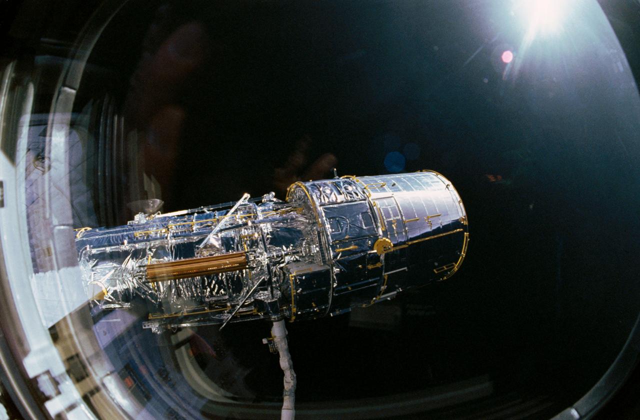
View taken through overhead window W7 aboard Discovery, Orbiter Vehicle (OV) 103, shows the Hubble Space Telescope (HST) grappled by the remote manipulator system (RMS) and held in a 90 degree pitch position against the blackness of space. The solar array (SA) panel (center) and the high gain antennae (HGA) (on either side) are visible along the Support System Module (SSM) forward shell prior to deployment during STS-31.
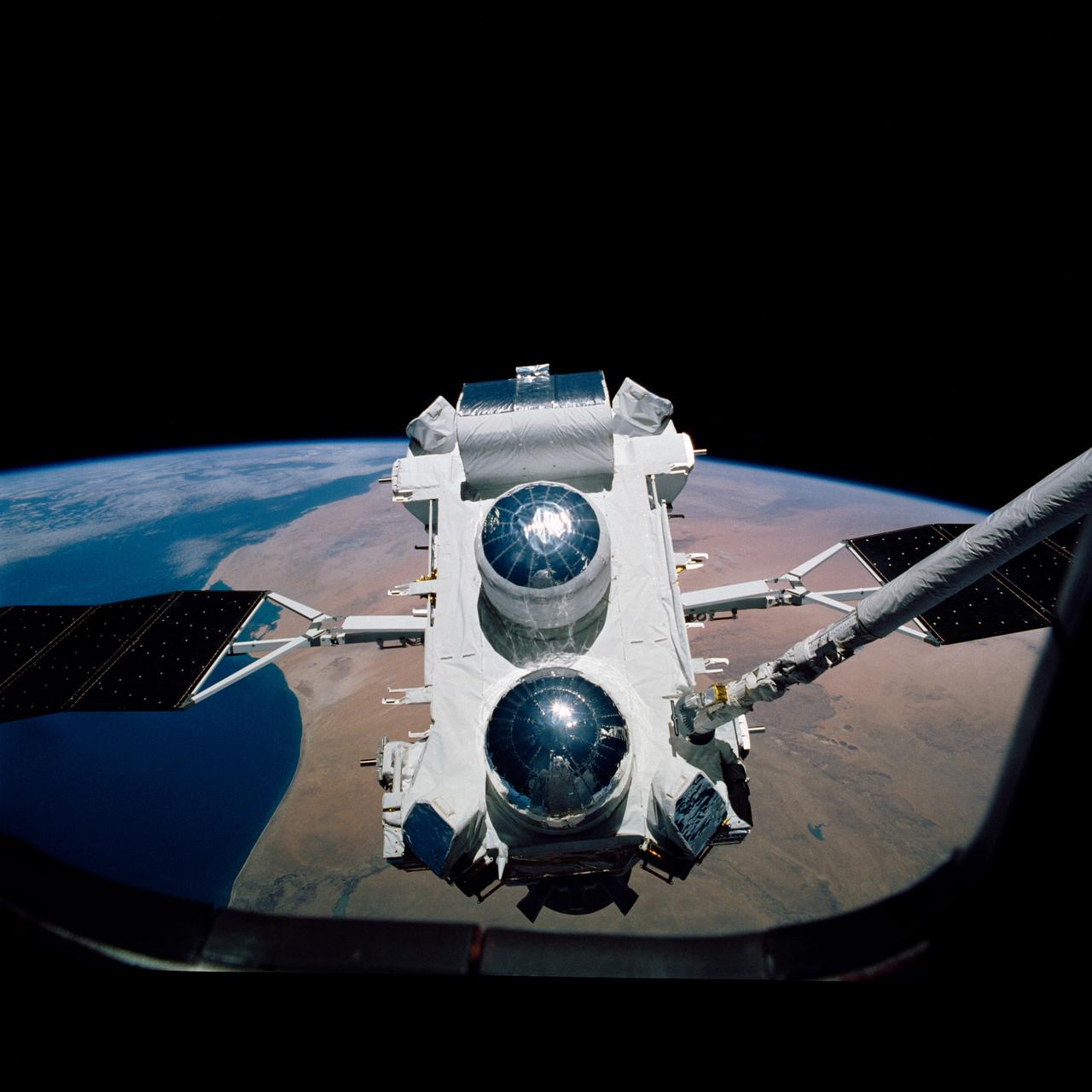
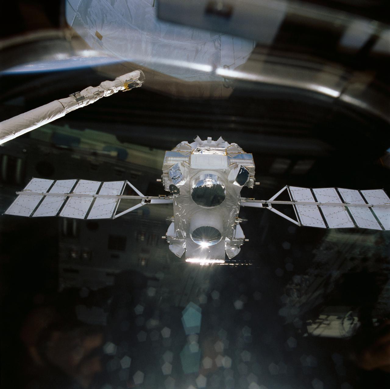
Backdropped against the Earth's surface, the Gamma Ray Observatory (GRO) with its solar array (SA) panels deployed is grappled by the remote manipulator system (RMS) during STS-37 systems checkout. GRO's four complement instruments are visible: the Energetic Gamma Ray Experiment Telescope (EGRET) (at the bottom); the Imaging Compton Telescope (COMPTEL) (center); the Oriented Scintillation Spectrometer Experiment (OSSE) (top); and Burst and Transient Source Experiment (BATSE) (on four corners). The view was taken by STS-37 crew through an aft flight deck overhead window.
Atlantis', Orbiter Vehicle (OV) 104's, remote manipulator system (RMS) releases Gamma Ray Observatory (GRO) during STS-37 deployment. Visible on the GRO as it drifts away from the RMS end effector are the four complement instruments: the Energetic Gamma Ray Experiment (bottom); Imaging Compton Telescope (COMPTEL) (center); Oriented Scintillation Spectrometer Experiment (OSSE) (top); and Burst and Transient Source Experiment (BATSE) (at four corners). GRO's solar array (SA) panels are extended and are in orbit configuration. View was taken through aft flight deck window which reflects some of the crew compartment interior.
S61-E-002 (4 Dec 1993) --- This view, backdropped against the blackness of space shows one of two original Solar Arrays (SA) on the Hubble Space Telescope (HST). The scene was photographed from inside Endeavour's cabin with an Electronic Still Camera (ESC), and down linked to ground controllers soon afterward. This view features the minus V-2 panel. Endeavour's crew captured the HST on December 4, 1993 in order to service the telescope over a period of five days. Four of the crew members will work in alternating pairs outside Endeavour's shirt sleeve environment to service the giant telescope. Electronic still photography is a relatively new technology which provides the means for a handheld camera to electronically capture and digitize an image with resolution approaching film quality. The electronic still camera has flown as an experiment on several other shuttle missions.
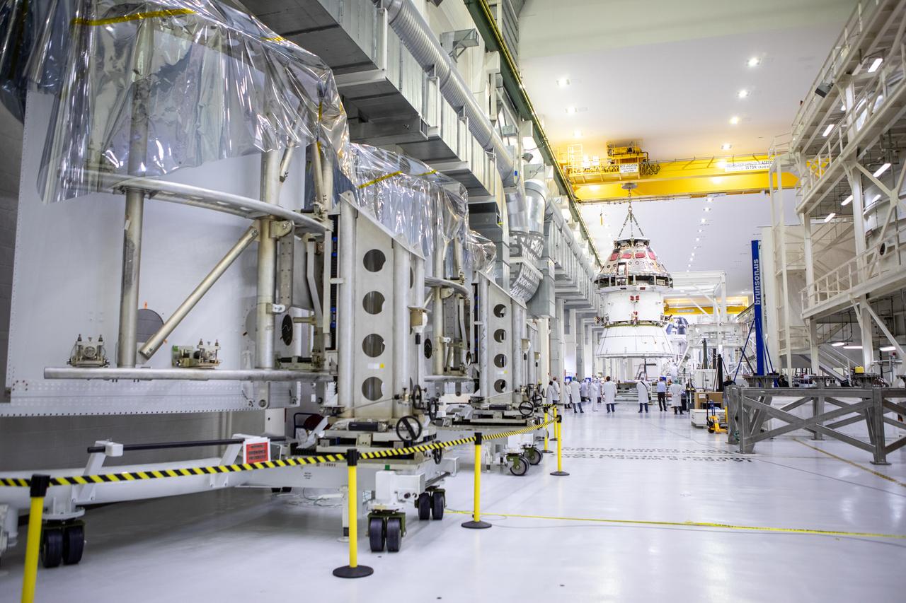
Technicians at NASA’s Kennedy Space Center in Florida work to safely return the Artemis I Orion spacecraft to the FAST cell after completing the installation of the spacecraft adapter (SA) cone inside the Neil Armstrong Operations and Checkout Building on Aug. 20, 2020. This is one of the final major hardware operations the spacecraft will undergo during closeout processing prior to being integrated with the Space Launch System (SLS) rocket in preparation for the first Artemis mission. The spacecraft adapter cone connects the bottom portion of Orion’s service module to the top part of the rocket known as the interim cryogenic propulsion stage (ICPS). In view at left in the foreground are the Spacecraft Adapter Jettison Fairing panels that will protect Orion’s service module from the environment around it during the ascent. Orion will fly on the agency’s Artemis I mission – the first in a series of increasingly complex missions to the Moon that will ultimately lead to the exploration of Mars.

S61-E-003 (4 Dec 1993) --- This medium close-up view of one of two original Solar Arrays (SA) on the Hubble Space Telescope (HST) was photographed with an Electronic Still Camera (ESC), and down linked to ground controllers soon afterward. This view shows the cell side of the minus V-2 panel. Endeavour's crew captured the HST on December 4, 1993 in order to service the telescope over a period of five days. Four of the crew members will work in alternating pairs outside Endeavour's shirt sleeve environment to service the giant telescope. Electronic still photography is a relatively new technology which provides the means for a handheld camera to electronically capture and digitize an image with resolution approaching film quality. The electronic still camera has flown as an experiment on several other shuttle missions.
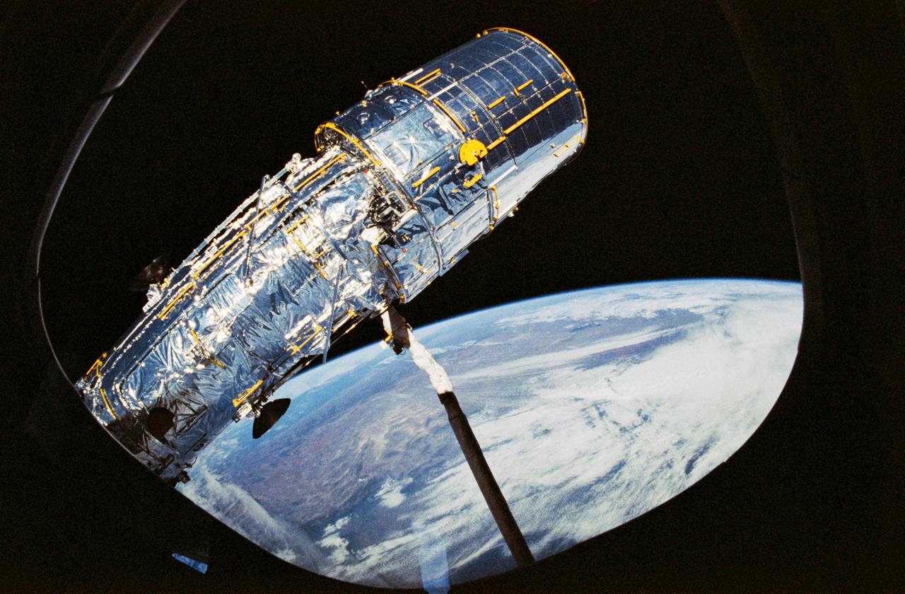
STS031-10-023 (25 April 1990) --- View of the Hubble Space Telescope (HST) on the end of Discovery's Remote Manipulator System (RMS) arm prior to deployment of its antennae and solar array panels.
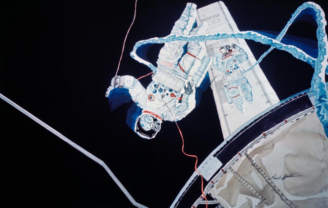
S75-21432 (March 1975) --- An artist's concept illustrating a scene during the June 7, 1973 Skylab 2 extravehicular activity in Earth orbit when astronauts Joseph P. Kerwin (larger figure) and Charles Conrad Jr. cut the aluminum strapping which prevented the Skylab Orbital Workshop solar array system wing from deploying. The solar panel was successfully deployed. The painting is by artist Paul Fjeld. The action portrayed here is about two to four seconds after using the beam erection tether, the two crewmen broke the frozen SAS beam actuators. This artistic effort took weeks to research and a day and a half to paint. Fjeld said that he needed some hundred or so photographs to get all the details for the painting. He struggled through about 300 pages of transcripts from the flight. Also, he used several pages of teleprinter messages which were the actual instructions on the EVA that the two astronauts used in flight. Photo credit: NASA