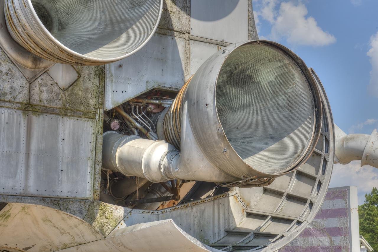
CLOSE-UP OF H-1 ENGINE INSTALLED ON SATURN S-1B STAGE (SA-T) NEAR PROPULSION AND STRUCTURAL TEST FACILITY (BUILDING 4572) AT THE GEORGE C. MARSHALL SPACE FLIGHT CENTER.
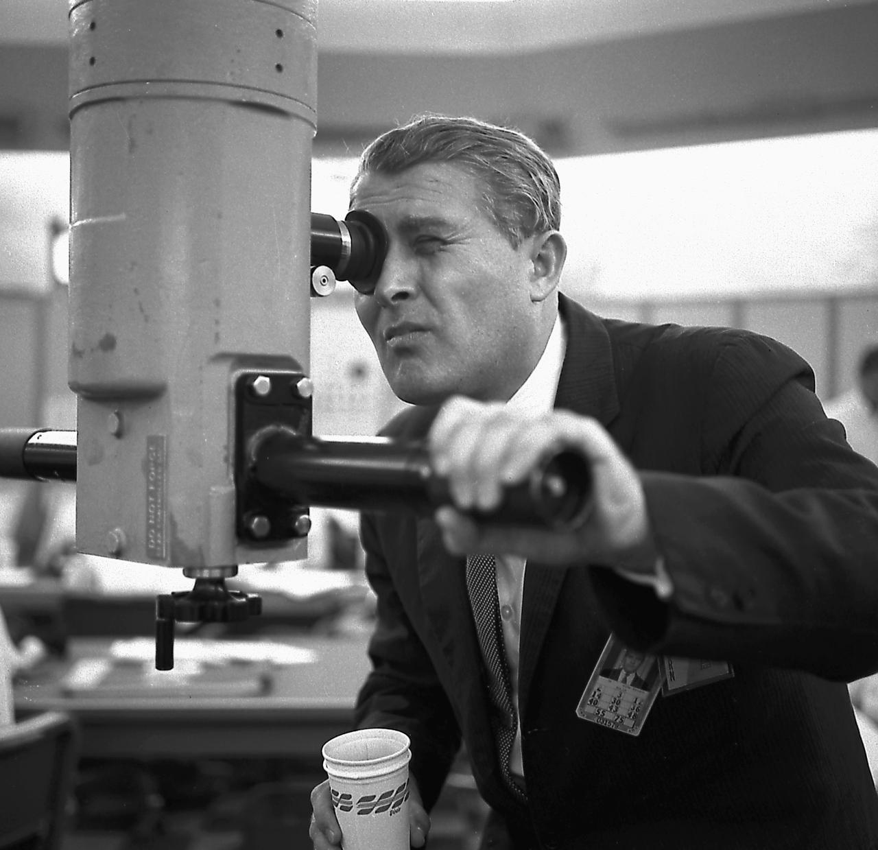
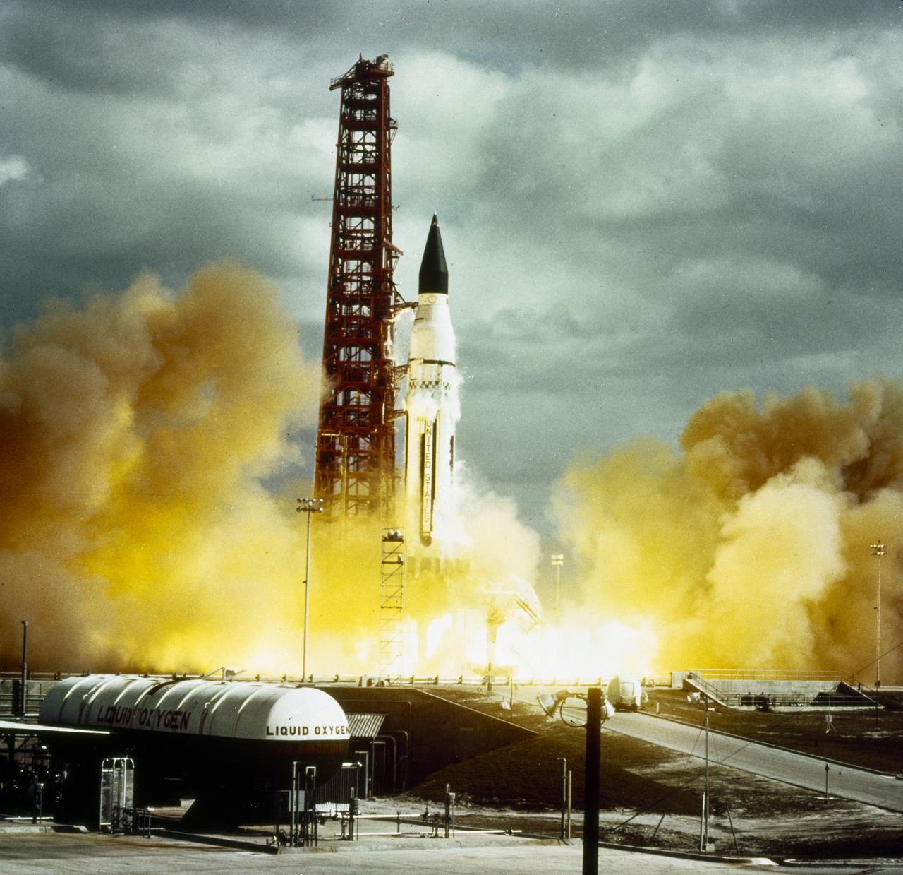
Dr. von Braun watches the Saturn 1 (SA-1) launch through a scope from the blockhouse 34 on October 27, 1961. The SA-1 was the first launch of Saturn launch vehicles developed at the Marshall Space Flight Center (MSFC) under the direction of Dr. von Braun. The flight demonstrated the validity of the clustered engine concept and launched dummy upper stages.
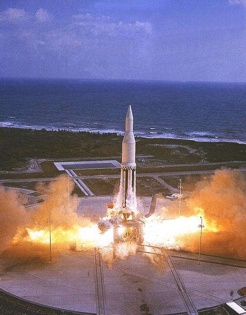
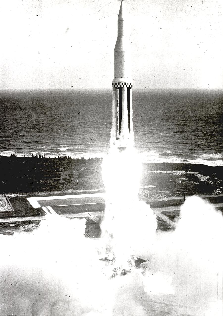
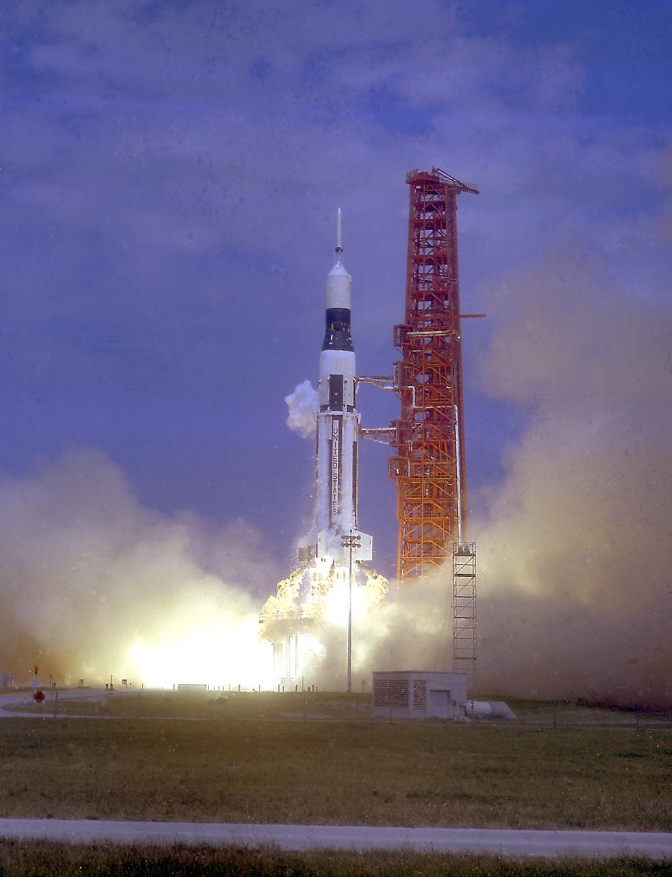
The Marshall Space Flight Center's first Saturn I vehicle, SA-1, lifts off from Cape Canaveral, Florida, on October 27, 1961. This early configuration, Saturn I Block I, 162 feet tall and weighing 460 tons, consisted of the eight H-1 engines S-I stage and the dummy second stage (S-IV stage).
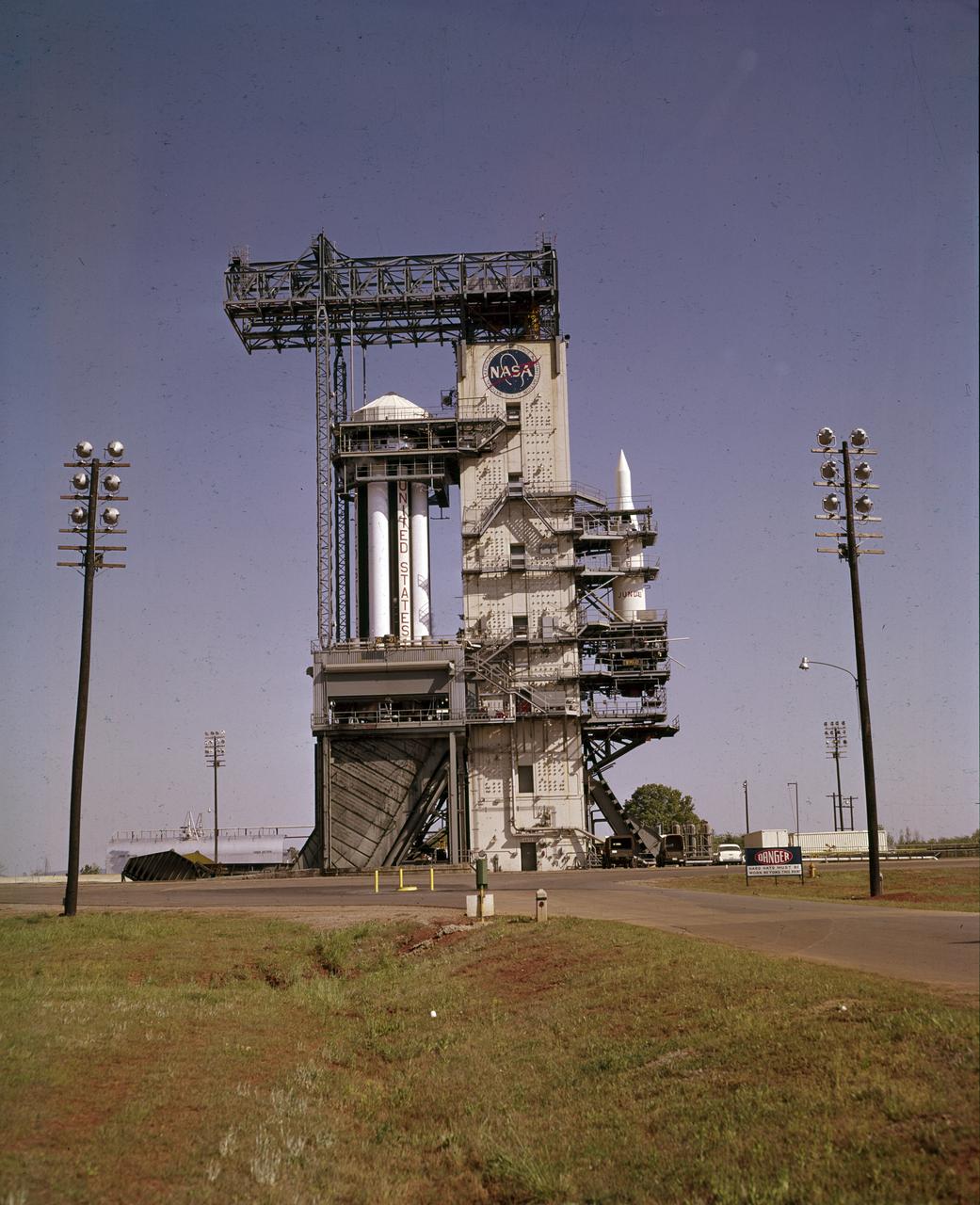
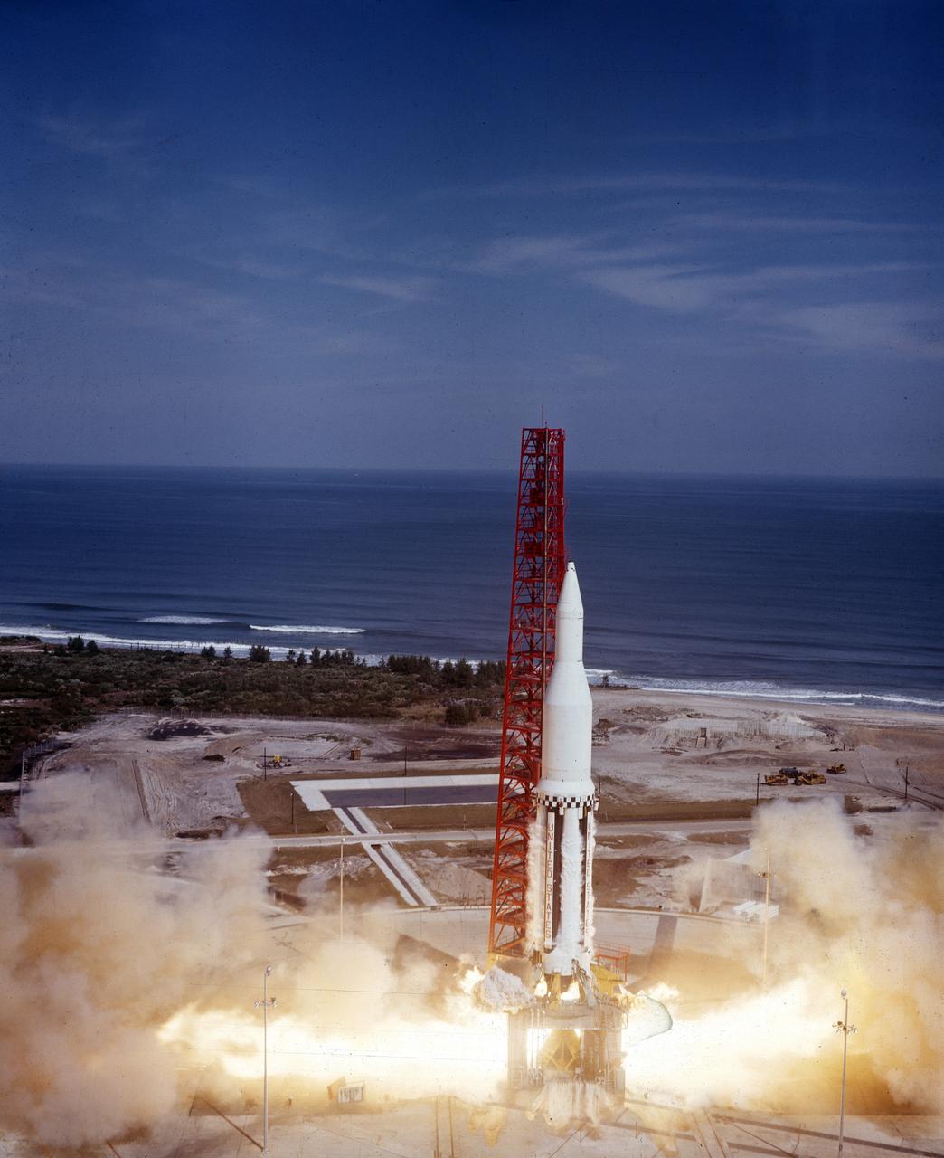
On October 27, 1961, the Marshall Space Flight Center (MSFC) and the Nation marked a high point in the 3-year-old Saturn development program when the first Saturn vehicle flew a flawless 215-mile ballistic trajectory from Cape Canaveral, Florida. SA-1 is pictured here, five months before launch, in the MSFC test stand on May 16, 1961. Developed and tested at MSFC under the direction of Dr. Wernher von Braun, SA-1 incorporated a Saturn I, Block I engine. The typical height of a Block I vehicle was approximately 163 feet. and had only one live stage. It consisted of eight tanks, each 70 inches in diameter, clustered around a central tank, 105 inches in diameter. Four of the external tanks were fuel tanks for the RP-1 (kerosene) fuel. The other four, spaced alternately with the fuel tanks, were liquid oxygen tanks, as was the large center tank. All fuel tanks and liquid oxygen tanks drained at the same rates respectively. The thrust for the stage came from eight H-1 engines, each producing a thrust of 165,000 pounds, for a total thrust of over 1,300,000 pounds. The engines were arranged in a double pattern. Four engines, located inboard, were fixed in a square pattern around the stage axis and canted outward slightly, while the remaining four engines were located outboard in a larger square pattern offset 40 degrees from the inner pattern. Unlike the inner engines, each outer engine was gimbaled. That is, each could be swung through an arc. They were gimbaled as a means of steering the rocket, by letting the instrumentation of the rocket correct any deviations of its powered trajectory. The block I required engine gimabling as the only method of guiding and stabilizing the rocket through the lower atmosphere. The upper stages of the Block I rocket reflected the three-stage configuration of the Saturn I vehicle.
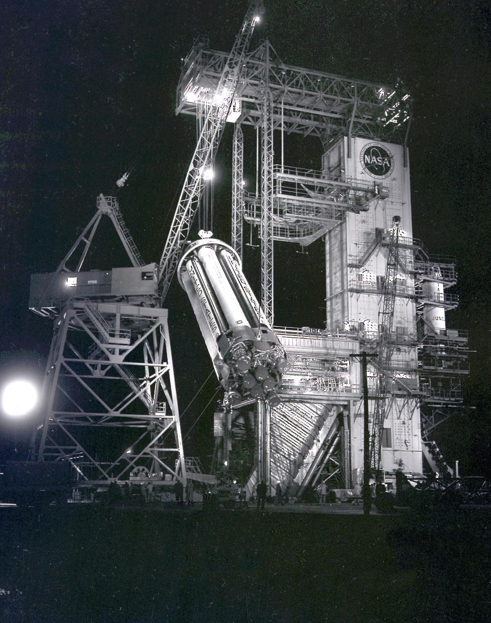
This night photograph depicts the SA-1 booster (Saturn I S-I stage) being removed from the test stand after the first flight qualification testing at the Marshall Space Flight Center (MSFC).
On October 27, 1961, the Marshall Space Flight Center and the Nation marked a high point in the 3-year-old Saturn development program when the first Saturn vehicle flew a flawless 215-mile ballistic trajectory from Cape Canaveral, Florida. The 162-foot-tall rocket weighed 925,000 pounds and employed a dummy second stage.
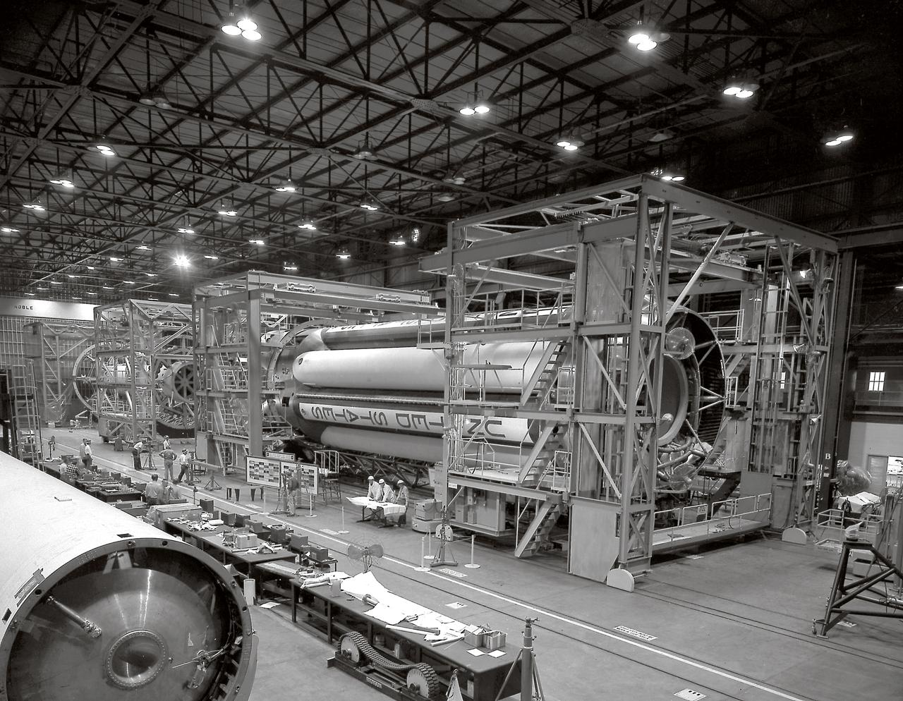
The S-I stages for the Saturn I (SA-1 at right and SA-2 at left) are being assembled at the Marshall Space Flight Center, building 4705. The Saturn I S-I stage had eight H-1 engines clustered, using liquid oxygen/kerosene-1 (LOX/RP-1) propellants capable of producing a total of 1,500,000 pounds of thrust.
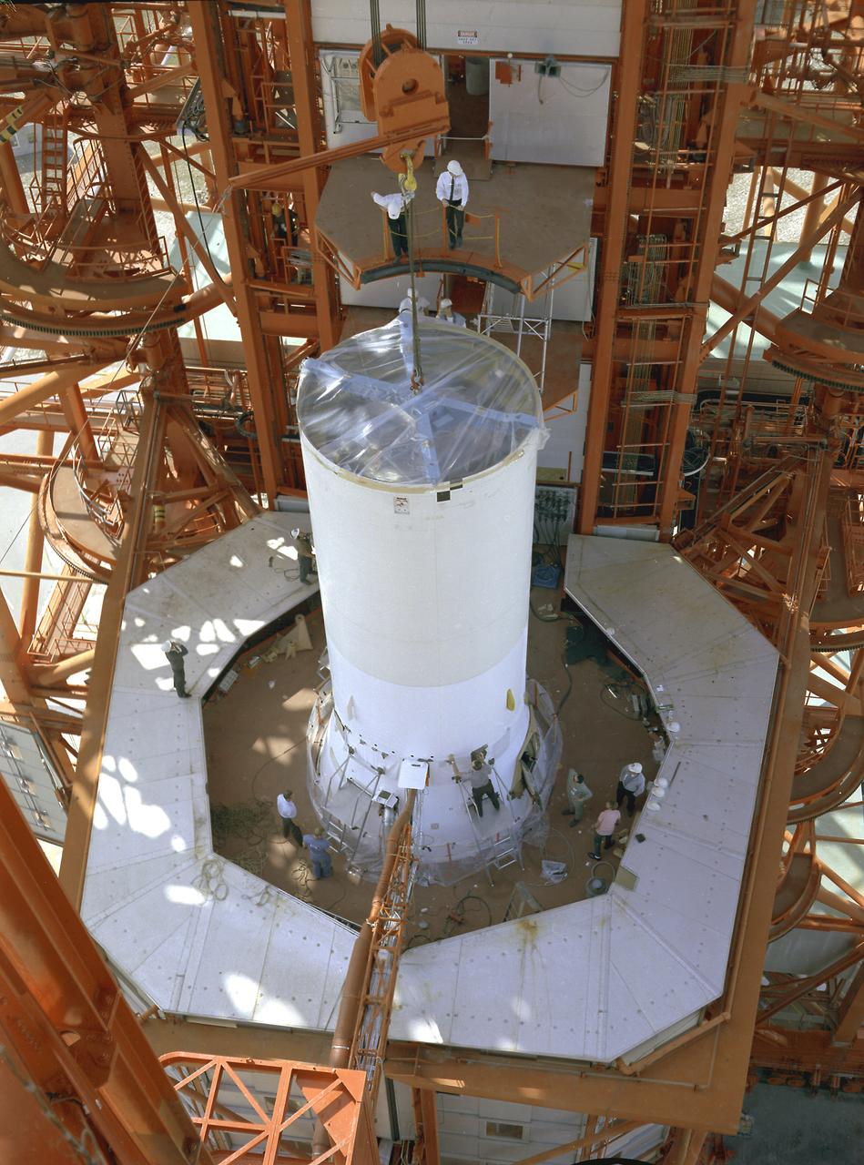
Pegasus-1, meteoroid detection satellite, installed on Saturn I (SA-9 mission) S-IV stage, January 13, 1965. The satellite was used to obtain data on frequency and penetration of the potentially hazardous micrometeoroids in low Earth orbits and to relay the information back to Earth. SA-9 was launched on February 16, 1965 and the Pegasus-1 satellite was the first operational payload for Saturn I.
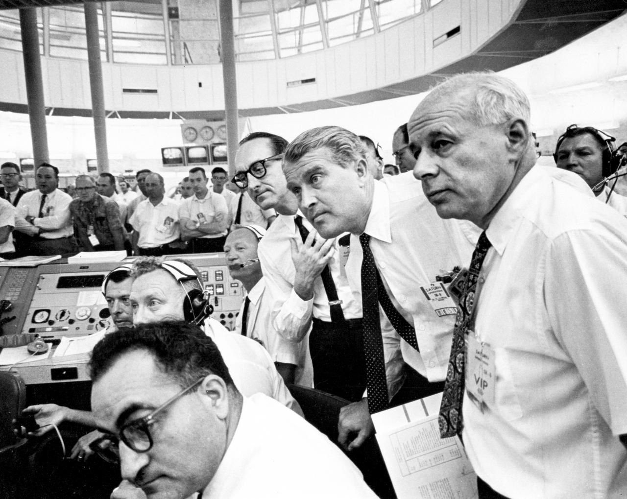
This photograph depicts an intense moment during the SA-6 launch at the Firing Room. Dr. von Braun, Director of the Marshall Space Flight Center (MSFC) is at center; to his left is Dr. George Mueller, Associate Director for Marned Space Flight; and far right is Dr. Eberhard Rees, Director for Research and Development, MSFC. The SA-6, the sixth flight of the Saturn 1 vehicle, launched a S-IV stage (a second stage) and an Apollo boilerplate spacecraft.
The launch of the SA-7 (Saturn I Block II) was on September 18, 1964. The SA-7 mission was the second orbital flight of the S-IV stage (second stage) with the payload consisting of the Apollo command and service module's instrument unit. The Saturn I Block II vehicle had two live stages, and were basically in the two-stage configuration of the Saturn I vehicle. While the tank arrangement and the engine patterns were the same, there were marked changes between the Block I and II versions. The first stage (S-I stage) was an improved version of the Block I S-I stage. The Block II S-1 stage had eight fins added for greater aerodynamic stability in the lower atmosphere.
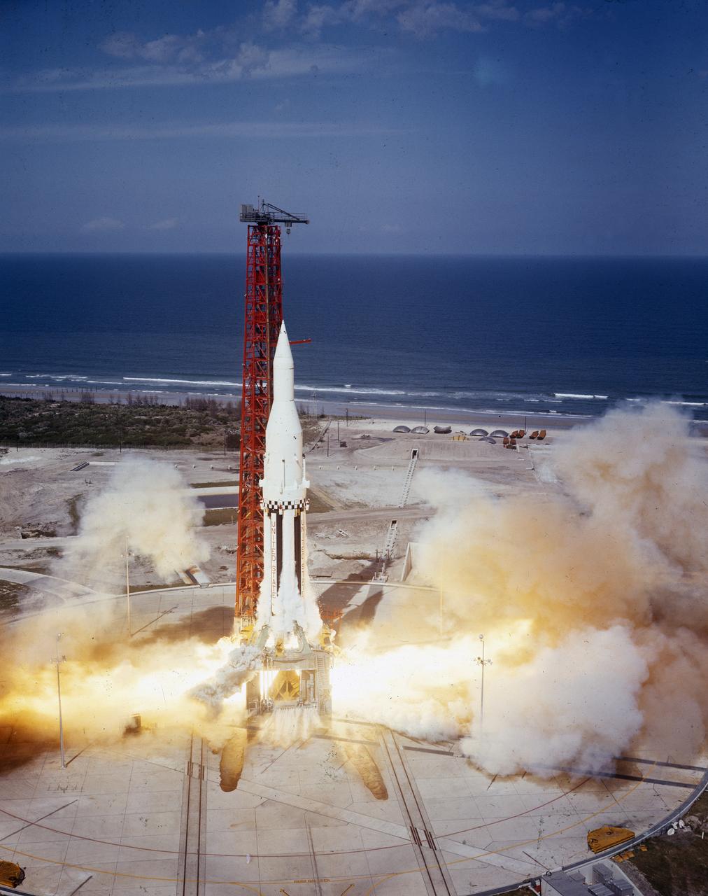
The Saturn I (SA-4) flight lifted off from Kennedy Space Center launch Complex 34, March 28, 1963. The fourth launch of Saturn launch vehicles developed at the Marshall Space Flight Center (MSFC), under the direction of Dr. Wernher von Braun, incorporated a Saturn I, Block I engine. The typical height of a Block I vehicle was approximately 163 feet and had only one live stage. It consisted of eight tanks, each 70 inches in diameter, clustered around a central tank, 105 inches in diameter. Four of the external tanks were fuel tanks for the RP-1 (kerosene) fuel. The other four, spaced alternately with the fuel tanks, were liquid oxygen tanks as was the large center tank. All fuel tanks and liquid oxygen tanks drained at the same rates respectively. The thrust for the stage came from eight H-1 engines, each producing a thrust of 165,000 pounds, for a total thrust of over 1,300,000 pounds. The engines were arranged in a double pattern. Four engines, located inboard, were fixed in a square pattern around the stage axis and canted outward slightly, while the remaining four engines were located outboard in a larger square pattern offset 40 degrees from the inner pattern. Unlike the inner engines, each outer engine was gimbaled. That is, each could be swung through an arc. They were gimbaled as a means of steering the rocket, by letting the instrumentation of the rocket correct any deviations of its powered trajectory. The block I required engine gimabling as the only method of guiding and stabilizing the rocket through the lower atmosphere. The upper stages of the Block I rocket reflected the three-stage configuration of the Saturn I vehicle. Like SA-3, the SA-4 flight’s upper stage ejected 113,560 liters (30,000 gallons) of ballast water in the upper atmosphere for "Project Highwater" physics experiment. Release of this vast quantity of water in a near-space environment marked the second purely scientific large-scale experiment. The SA-4 was the last Block I rocket launch.
The Saturn I (SA-4) flight lifted off from Kennedy Space Center launch Complex 34, March 28, 1963. The fourth launch of Saturn launch vehicles, developed at the Marshall Space Flight Center (MSFC) under the direction of Dr. Wernher von Braun, incorporated a Saturn I, Block I engine. The typical height of a Block I vehicle was approximately 163 feet and had only one live stage. It consisted of eight tanks, each 70 inches in diameter, clustered around a central tank, 105 inches in diameter. Four of the external tanks were fuel tanks for the RP-1 (kerosene) fuel. The other four, spaced alternately with the fuel tanks, were liquid oxygen tanks as was the large center tank. All fuel tanks and liquid oxygen tanks drained at the same rates respectively. The thrust for the stage came from eight H-1 engines, each producing a thrust of 165,000 pounds, for a total thrust of over 1,300,000 pounds. The engines were arranged in a double pattern. Four engines, located inboard, were fixed in a square pattern around the stage axis and canted outward slightly, while the remaining four engines were located outboard in a larger square pattern offset 40 degrees from the inner pattern. Unlike the inner engines, each outer engine was gimbaled. That is, each could be swung through an arc. They were gimbaled as a means of steering the rocket, by letting the instrumentation of the rocket correct any deviations of its powered trajectory. The block I required engine gimabling as the only method of guiding and stabilizing the rocket through the lower atmosphere. The upper stages of the Block I rocket reflected the three-stage configuration of the Saturn I vehicle. Like SA-3, the SA-4 flight’s upper stage ejected 113,560 liters (30,000 gallons) of ballast water in the upper atmosphere for "Project Highwater" physics experiment. Release of this vast quantity of water in a near-space environment marked the second purely scientific large-scale experiment. The SA-4 was the last Block I rocket launch.
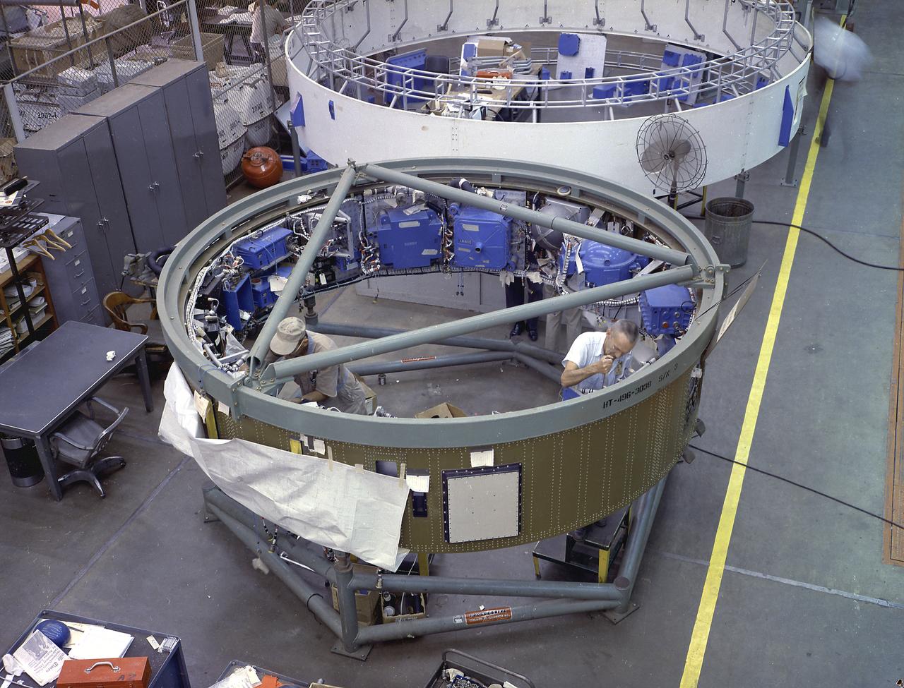
This image depicts a high angle view of technicians working on the instrument unit (IU) component assembly for the SA-8 mission in Marshall Space Flight Center's building 4705. A thin, circular structure, only 1-meter high and 7.6 meters in diameter, the IU was sandwiched between the S-IV and Apollo spacecraft. Packed inside were the computers, gyroscopes, and assorted black boxes necessary to keep the launch vehicle properly functioning and on its course.
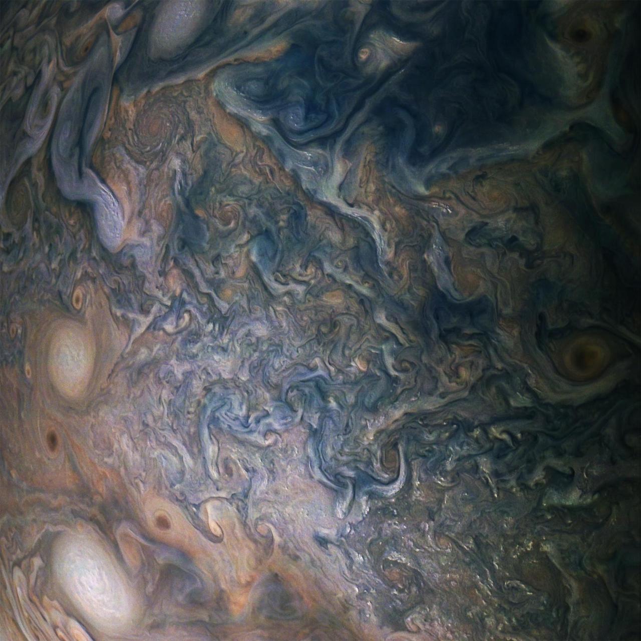
A multitude of bright white "pop-up" storms in this Jupiter cloudscape appear in this image from NASA's Juno spacecraft. This color-enhanced image was taken at 1:55 p.m. PDT (4:55 p.m. EDT) on Oct. 29, 2018, as the spacecraft performed its 16th close flyby of Jupiter. Citizen scientists Gerald Eichstädt and Seán Doran created this image using data from the spacecraft's JunoCam imager. https://photojournal.jpl.nasa.gov/catalog/PIA22935 **Image Credit: Enhanced Image by Gerald Eichstädt and Seán Doran (CC BY-NC-SA) based on images provided courtesy of NASA/JPL-Caltech/SwRI/MSSS
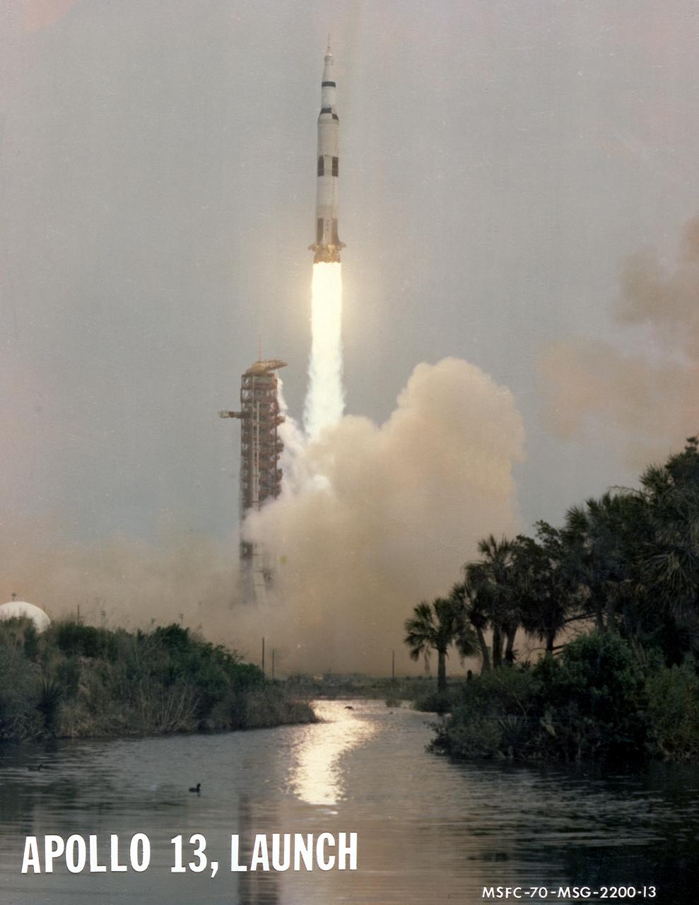
The third marned lunar landing mission, Apollo 13 (SA-508), with three astronauts: Mission commander James A. Lovell Jr., Lunar Module pilot Fred W. Haise Jr., and Command Module pilot John L. Swigert Jr., lifted off from the Kennedy Space Center launch complex 39A on April 11, 1970. The mission was aborted after 56 hours of flight, 205,000 miles from Earth, when an oxygen tank in the service module exploded. The Command Module, Odyssey, carrying the three astronauts, safely splashed down in the Pacific Ocean at 1:08 p.m. EST, April 17, 1970.
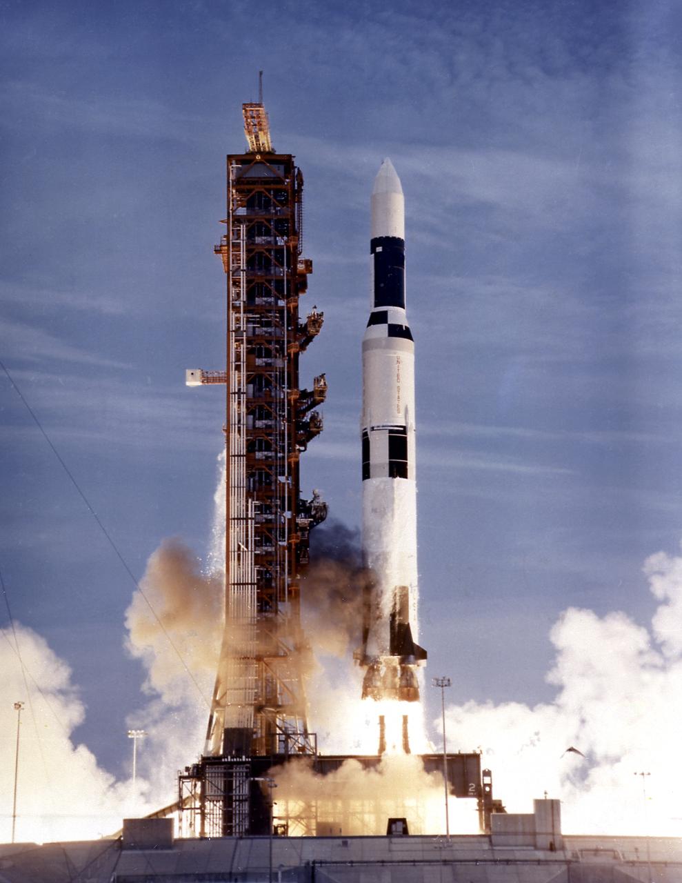
This photograph shows the launch of the SA-513, a modified unmarned two-stage Saturn V vehicle for the Skylab-1 mission, which placed the Skylab cluster into the Earth orbit on May 14, 1973. The initial step in the Skylab mission was the launch of a two-stage Saturn V booster, consisting of the S-IC first stage and the S-II second stage, from Launch Complex 39A at the Kennedy Space Center in Florida. Its payload was the unmanned Skylab, which consisted of the Orbital Workshop, the Airlock Module, the Multiple Docking Adapter, the Apollo Telescope Mount and an Instrument Unit.
Developed at MSFC under the direction of Dr. Wernher von Braun, the SA-5 incorporated a Saturn I, Block II engine. Launched on January 29, 1964, SA-5 was the first two stage (Block II) Saturn with orbital capability and performed the first test of Instrument Unit and successful stage separation. Block II vehicles had two live stages, and were basically in the two-stage configuration of the Saturn I vehicle. There were marked changes between the Block I and II versions. The Block II S-I stage had eight fins added for greater aerodynamic stability in the lower atmosphere. All Block II H-1 engines had a thrust of 188,000 pounds each for a combined thrust over 1,500,000 pounds. The Block II second stage (S-IV) had six RL-10 hydrogen-oxygen engines, each producing a thrust of 15,000 pounds for a total combined thrust of 90,000 pounds. A motion picture camera capsule loated on stage I was successful recovered.
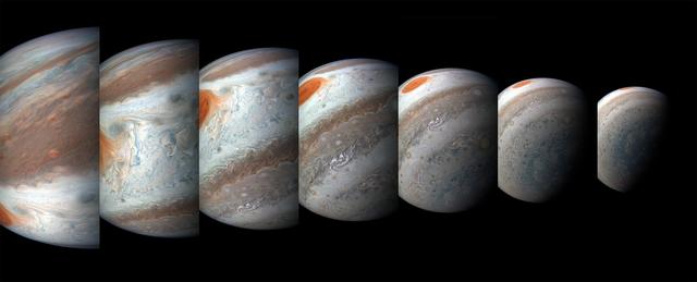
A south tropical disturbance has just passed Jupiter's iconic Great Red Spot and is captured stealing threads of orange haze from the Great Red Spot in this series of color-enhanced images from NASA's Juno spacecraft. From left to right, this sequence of images was taken between 2:57 a.m. and 3:36 a.m. PDT (5:57 a.m. and 6:36 a.m. EDT) on April 1, 2018, as the spacecraft performed its 12th close flyby of Jupiter. Citizen scientists Gerald Eichstädt and Seán Doran created this image using data from the spacecraft's JunoCam imager. https://photojournal.jpl.nasa.gov/catalog/PIA22937 ** Image Credit: Enhanced Image by Gerald Eichstädt and Seán Doran (CC BY-NC-SA) based on images provided courtesy of NASA/JPL-Caltech/SwRI/MSSS

During the Apollo 15 launch activities in the launch control center's firing room 1 at Kennedy Space Center, Dr. Wernher von Braun, NASA's Deputy Associate Administrator for planning, takes a closer look at the launch pad through binoculars. The fifth manned lunar landing mission, Apollo 15 (SA-510), carrying a crew of three astronauts: Mission commander David R. Scott, Lunar Module pilot James B. Irwin, and Command Module pilot Alfred M. Worden Jr., lifted off on July 26, 1971. Astronauts Scott and Irwin were the first to use a wheeled surface vehicle, the Lunar Roving Vehicle, or the Rover, which was designed and developed by the Marshall Space Flight Center, and built by the Boeing Company. Astronauts spent 13 days, nearly 67 hours, on the Moon's surface to inspect a wide variety of its geological features.
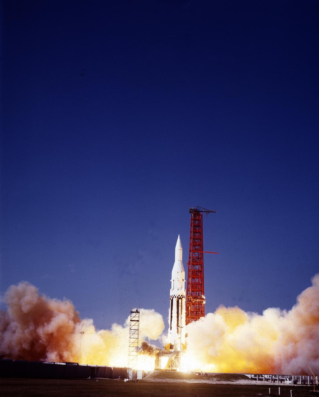
The Saturn I (SA-3) flight lifted off from Kennedy Space Center launch Complex 34, November 16, 1962. The third launch of Saturn launch vehicles, developed at the Marshall Space Flight Center (MSFC) under the direction of Dr. Wernher von Braun, incorporated a Saturn I, Block I engine. The typical height of a Block I vehicle was approximately 163 feet. and had only one live stage. It consisted of eight tanks, each 70 inches in diameter, clustered around a central tank, 105 inches in diameter. Four of the external tanks were fuel tanks for the RP-1 (kerosene) fuel. The other four, spaced alternately with the fuel tanks, were liquid oxygen tanks as was the large center tank. All fuel tanks and liquid oxygen tanks drained at the same rates respectively. The thrust for the stage came from eight H-1 engines, each producing a thrust of 165,000 pounds, for a total thrust of over 1,300,000 pounds. The engines were arranged in a double pattern. Four engines, located inboard, were fixed in a square pattern around the stage axis and canted outward slightly, while the remaining four engines were located outboard in a larger square pattern offset 40 degrees from the inner pattern. Unlike the inner engines, each outer engine was gimbaled. That is, each could be swung through an arc. They were gimbaled as a means of steering the rocket, by letting the instrumentation of the rocket correct any deviations of its powered trajectory. The block I required engine gimabling as the only method of guiding and stabilizing the rocket through the lower atmosphere. The upper stages of the Block I rocket reflected the three-stage configuration of the Saturn I vehicle. During the SA-3 flight, the upper stage ejected 113,560 liters (30,000 gallons) of ballast water in the upper atmosphere for "Project Highwater" physics experiment. The water was released at an altitude of 65 miles, where within only 5 seconds, it expanded into a massive ice cloud 4.6 miles in diameter. Release of this vast quantity of water in a near-space environment marked the first purely scientific large-scale experiment.
This images is one of two true-color images taken 12 minutes apart neatly captures storm movement in the southern hemisphere of Jupiter. NASA's Juno spacecraft took these images during its tenth close flyby of the gas giant planet on Dec. 16, 2017 at 10:12 a.m. PST (1:12 p.m. EST) and 10:24 a.m. PST (1:24 p.m. EST). At the time, the spacecraft was about 8,453 miles (13,604 kilometers) and 19,244 miles (30,970 kilometers) from the tops of the clouds above the planet, with the images centered on south latitudes of 27.96 degrees and 49.91 degrees. The animation reveals the cyclonic motion of the STB Ghost, a large elongated feature in Jupiter's South Temperate Belt. This feature is elongated in the east-west direction and is located near the center in these images. Citizen scientist Björn Jónsson processed the image using data from the JunoCam imager. An animation is available at https://photojournal.jpl.nasa.gov/catalog/PIA21982. - Enhanced image by Björn Jónsson (CC-NC-SA) based on images provided courtesy of NASA/JPL-Caltech/SwRI/MSSS
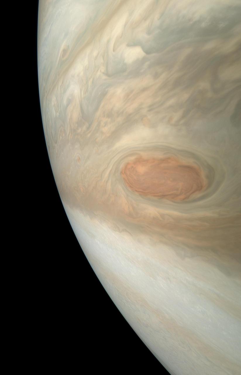
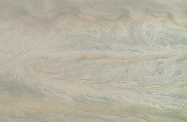
A swirling storm somersaults through Jupiter's South Equatorial Belt in this view taken by NASA's Juno spacecraft. This feature -- not to be confused with the planet's iconic Great Red Spot -- is escorted by several smaller, reddish vortices above and to the left. This natural color view offers an approximation of what Jupiter would look like to human eyes from Juno's vantage point near the time of closest approach in its orbit. Jupiter's stunning appearance is due to its atmosphere of colorful cloud bands and spots. The vivid red and orange hues are created by chemicals of uncertain composition called "chromophores." The image was taken at 10:28 p.m. PDT on July 15, 2018 (1:28 a.m. EDT on July 16), as the spacecraft performed its 14th close flyby of Jupiter. At the time, Juno was about 4,900 miles (8,000 kilometers) from the planet's cloud tops, above a southern latitude of 36 degrees. Citizen scientist Björn Jónsson created this image using data from the spacecraft's JunoCam imager. https://photojournal.jpl.nasa.gov/catalog/PIA22427. - Enhanced image by Björn Jónsson (CC-NC-SA) based on images provided courtesy of NASA/JPL-Caltech/SwRI/MSSS