
Limb Scan

Scanning the Rings
What a Scan!
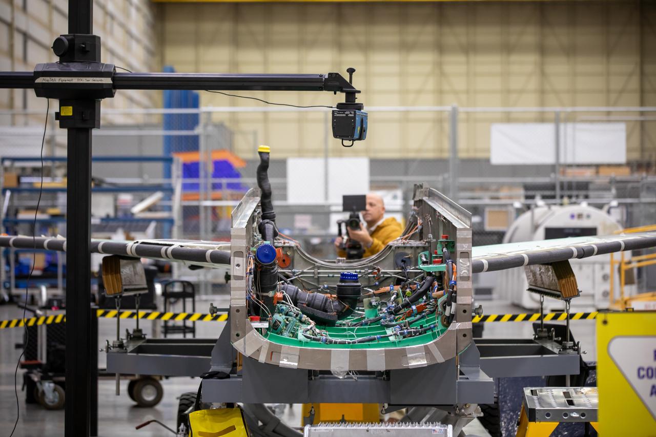
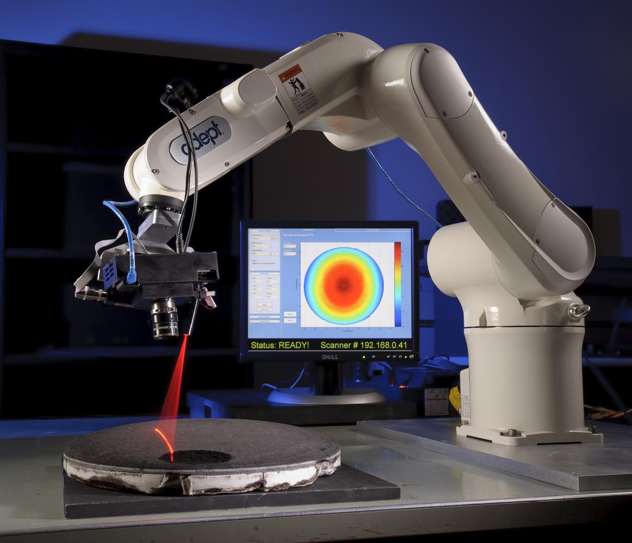
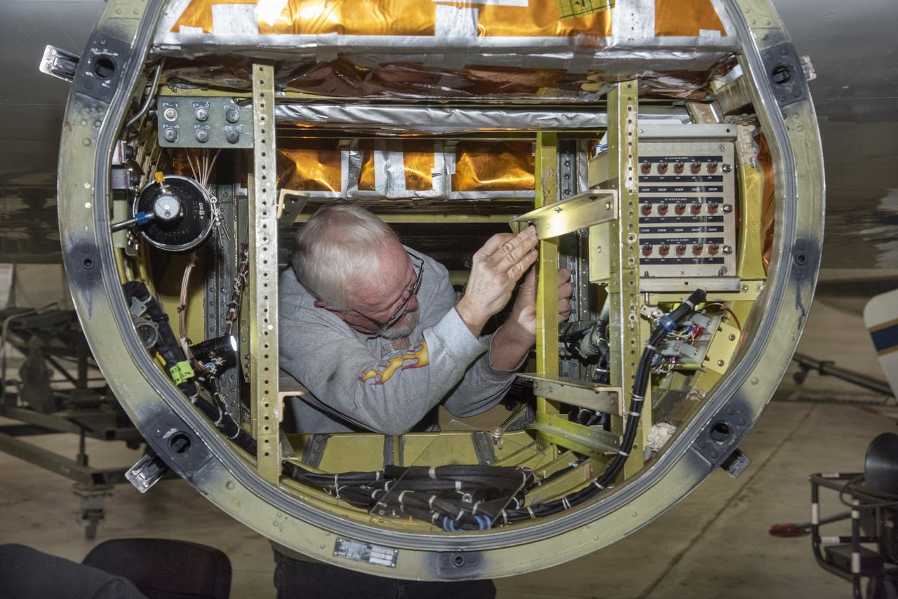
A laser scans the inside of the X-59 aircraft’s lower engine bay at Lockheed Martin Skunk Works in Palmdale, California. These scans can help identify potential hardware or wiring interferences prior to the final installation of the engine and lower tail.
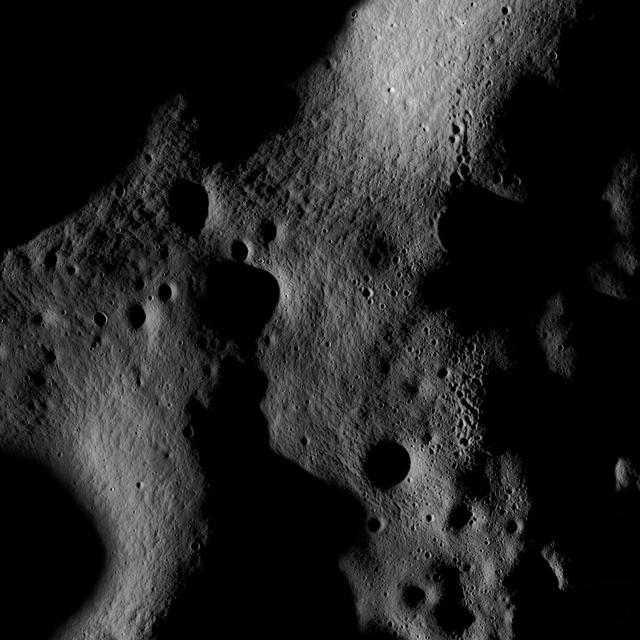
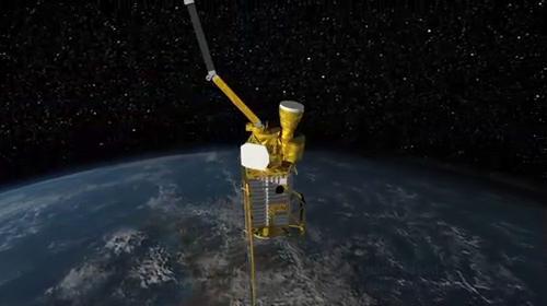
On July 4th the Narrow Angle Camera onboard NASA Lunar Reconnaissance Orbiter scanned its way towards the north pole at an altitude of 187 km, brushing past the crater Rozhdestvenskiy W.

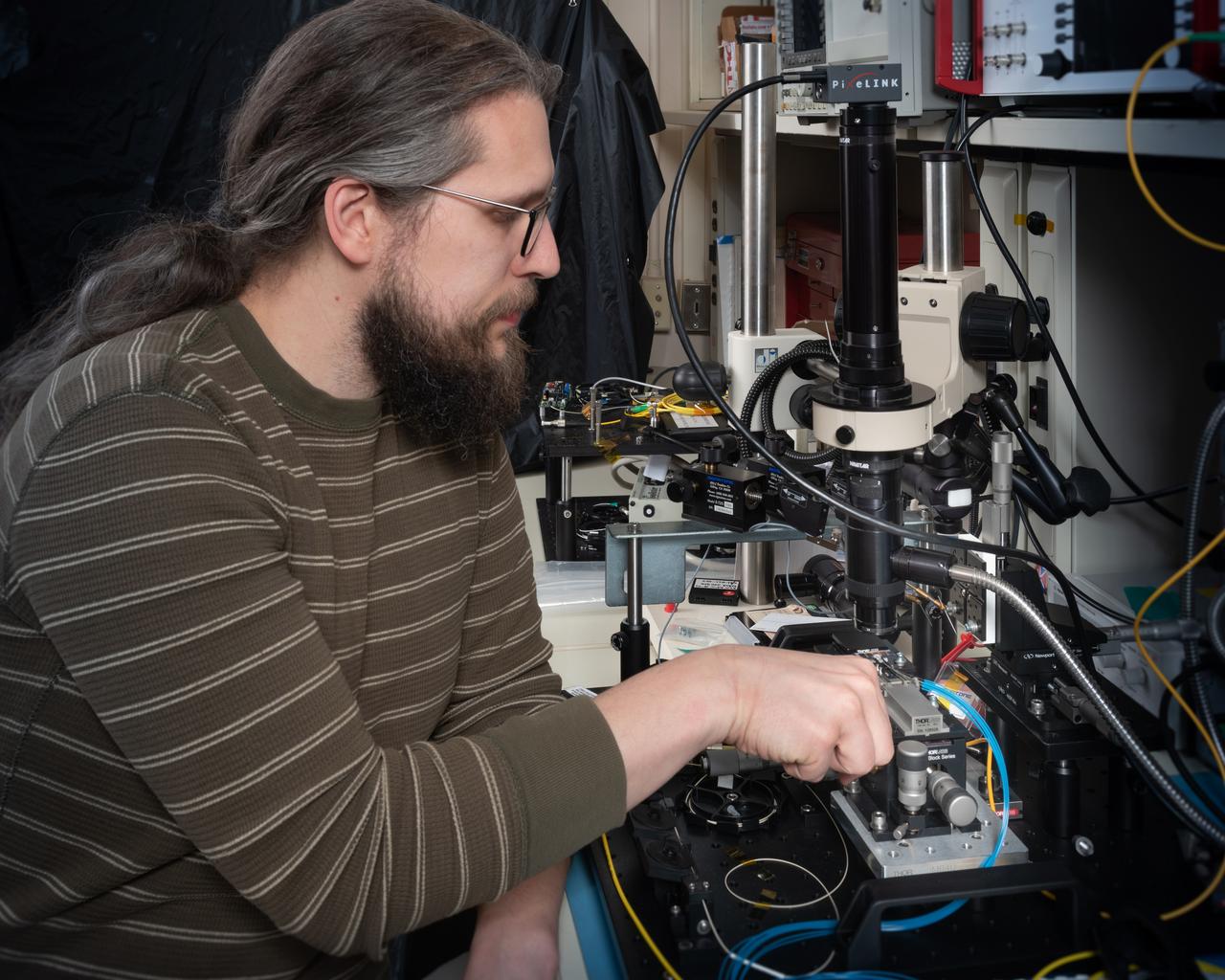
Engineer Erin Wilson adds aluminum tape to electrical cables to protect them from the cold during environmental testing of special optical equipment. These tests will verify the alignment of the actual flight instruments that will fly aboard NASA’s James Webb Space Telescope. "Because the flight science instruments detect infrared light, they must be extremely cold to work, and so the environment we test them in must be extremely cold too," Wilson says. Wilson is working in the Space Environment Simulator thermal-vacuum chamber at NASA's Goddard Space Flight Center in Greenbelt, Md. The subject of the testing is the Optical Telescope Element (OTE) Simulator, or OSIM. The hardware seen in the background is the Beam Image Analyzer, which will be used to measure OSIM. It sits above the OSIM, which is under the platform that Wilson is working on. The OSIM is about two stories tall and almost as wide as the whole test chamber. The job of the OSIM is to generate a beam of light just like the one that the real telescope optics will feed into the actual flight science instruments. Because the real flight science instruments will be used to test the real flight telescope, their alignment and performance have to be verified first, using OSIM, and before that can happen, the OSIM has to tested and verified. In space, the telescope optics act as Webb’s eye, and on the ground, the OSIM substitutes for the telescope optics, says Robert Rashford, manager for the OSIM as well as the Integrated Science Instrument Module (ISIM) Electronics Compartment. This hardware is being tested in an environment that mimics the hard vacuum and cold temperatures that Webb will experience in space. After Erin and others were done setting things up in the test chamber, Goddard engineers sealed it up, evacuated all the air and lowered the temperature of the equipment being tested to 42 Kelvin (-384-point-1 Fahrenheit or -231-point-1 Celsius). "It has taken a little over a month to get temperatures cold enough to duplicate the temperatures that Webb will see in operation in space," Rashford says. In the next couple weeks Rashford and the team of Goddard engineers will measure the OSIM with the Beam Image Analyzer. This extremely cold or “cryogenic” optical testing and verification process will likely take 90 days to complete. Laura Betz NASA's Goddard Space Flight Center, Greenbelt, Md. <b><a href="http://www.nasa.gov/audience/formedia/features/MP_Photo_Guidelines.html" rel="nofollow">NASA image use policy.</a></b> <b><a href="http://www.nasa.gov/centers/goddard/home/index.html" rel="nofollow">NASA Goddard Space Flight Center</a></b> enables NASA’s mission through four scientific endeavors: Earth Science, Heliophysics, Solar System Exploration, and Astrophysics. Goddard plays a leading role in NASA’s accomplishments by contributing compelling scientific knowledge to advance the Agency’s mission. <b>Follow us on <a href="http://twitter.com/NASA_GoddardPix" rel="nofollow">Twitter</a></b> <b>Like us on <a href="http://www.facebook.com/pages/Greenbelt-MD/NASA-Goddard/395013845897?ref=tsd" rel="nofollow">Facebook</a></b> <b>Find us on <a href="http://instagrid.me/nasagoddard/?vm=grid" rel="nofollow">Instagram</a></b>
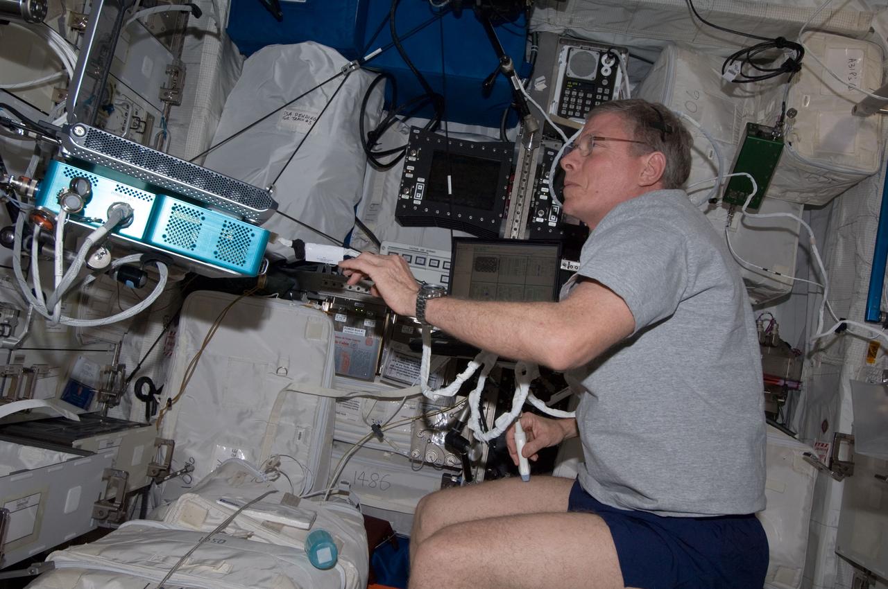
View of Integrated Cardiovascular (ICV) Echo Ultrasound Scan,in the Columbus module. ICV aims to quantify the extent,time course and clinical significance of cardiac atrophy (decrease in the size of the heart muscle) in space. Photo was taken during Expedition 34.
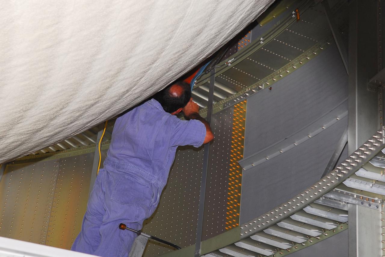
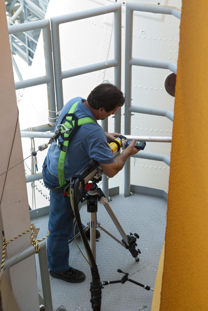
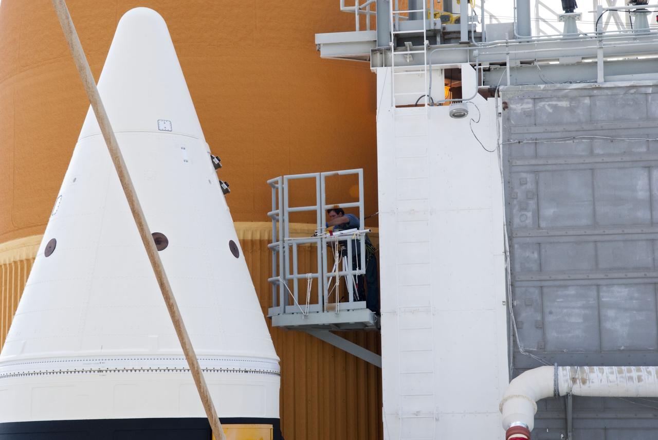
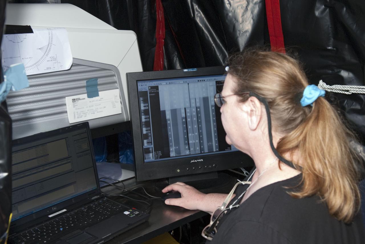
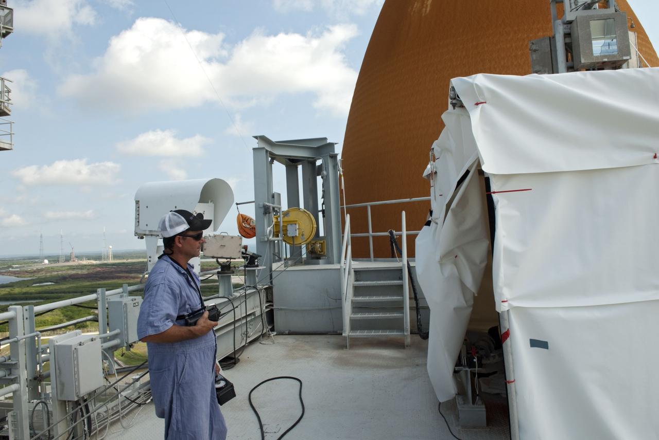
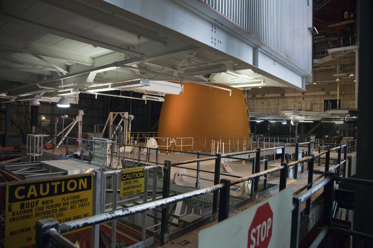
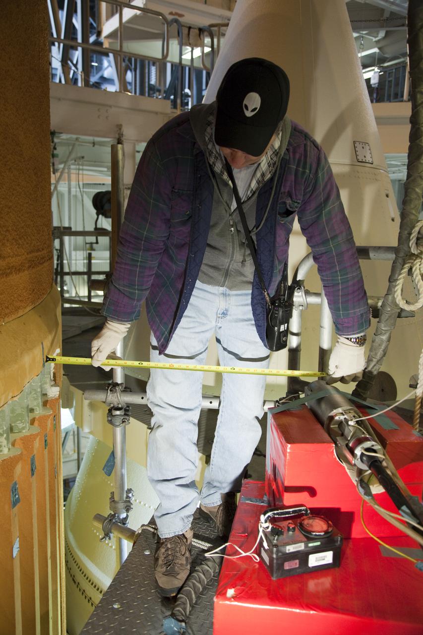
CAPE CANAVERAL, Fla. -- At NASA's Kennedy Space Center in Florida, technicians conduct Computed Radiography (CR) X-ray scans of 50 support beams, called stringers, on the shuttle-facing side of Atlantis' external tank at Launch Pad 39A. The hi-tech images will be taken of the tops and bottoms of the 21-foot long beams, which are located on the tank's intertank section. Here, a technician prepares an image plate inside the outertank. The scans follow a June 15th tanking test when the launch team filled then drained the tank of about 535,000 gallons of liquid hydrogen and liquid oxygen, just like for a launch. Earlier this year, managers directed teams to make the same stringer modifications to Atlantis' tank, ET-138, as they had after small cracks in the support beams of shuttle Discovery's STS-133 mission external tank were discovered. The scans will confirm there are no issues with Atlantis' tank. STS-135 Commander Chris Ferguson, Pilot Doug Hurley and Mission Specialists Sandy Magnus and Rex Walheim are targeted to lift off on space shuttle Atlantis July 8, taking with them the MPLM packed with supplies, logistics and spare parts to the International Space Station. The STS-135 mission also will fly a system to investigate the potential for robotically refueling existing satellites and return a failed ammonia pump module to help NASA better understand the failure mechanism and improve pump designs for future systems. STS-135 will be the 33rd flight of Atlantis, the 37th shuttle mission to the space station, and the 135th and final mission of NASA's Space Shuttle Program. For more information visit, www.nasa.gov/mission_pages/shuttle/shuttlemissions/sts135/index.html. Photo credit: NASA/Jim Grossmann
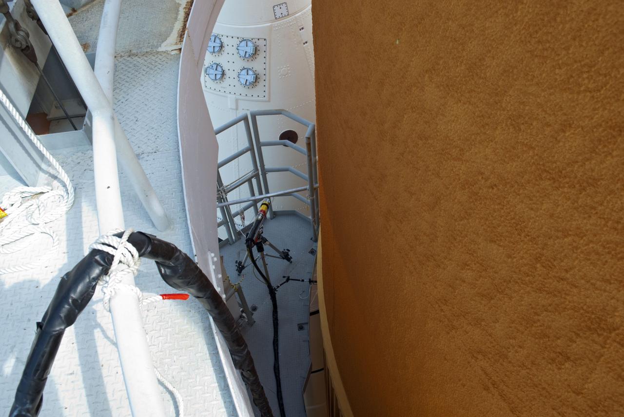
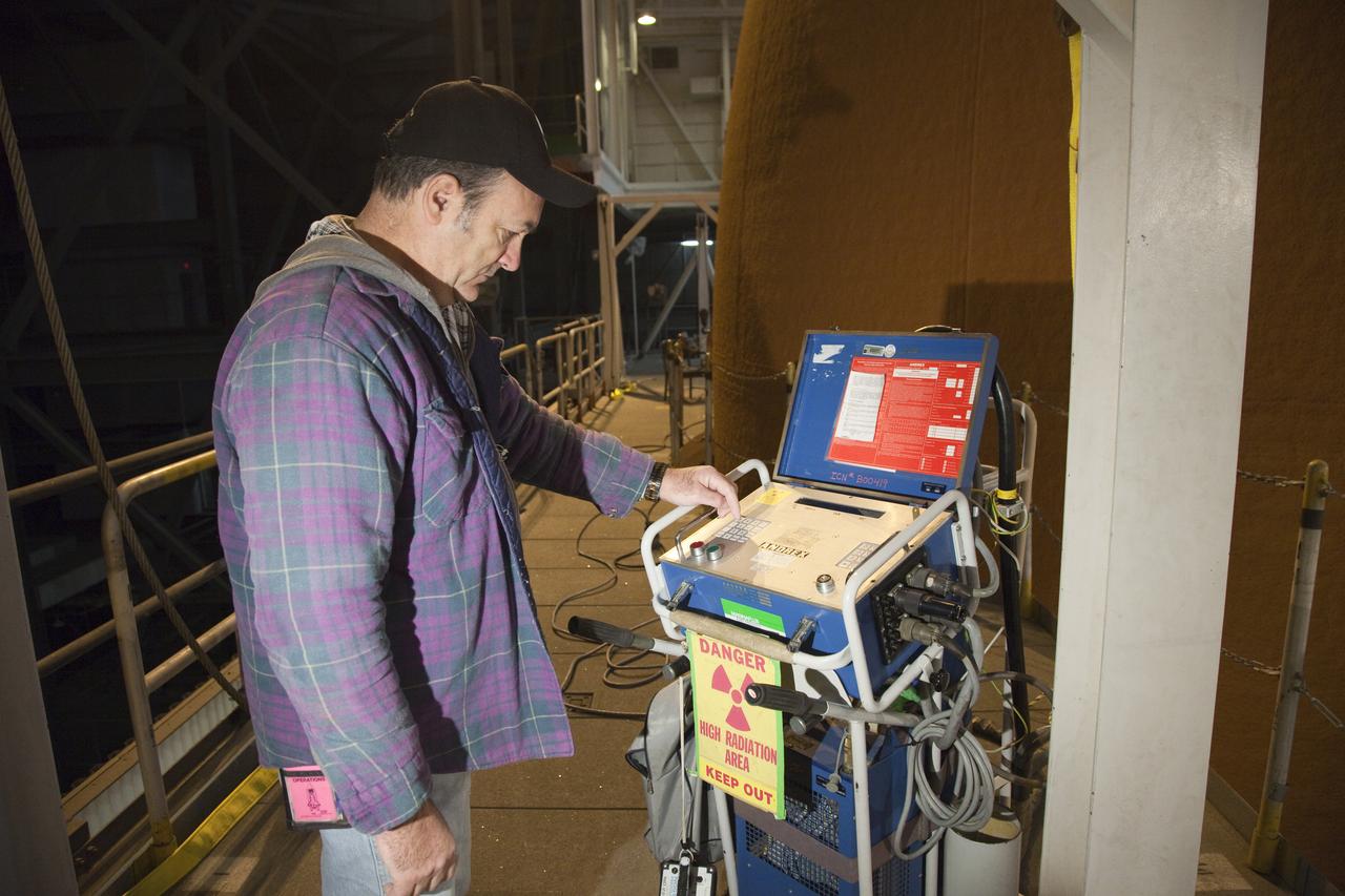
CAPE CANAVERAL, Fla. -- At NASA's Kennedy Space Center in Florida, technicians conduct Computed Radiography (CR) X-ray scans of 50 support beams, called stringers, on the shuttle-facing side of Atlantis' external tank at Launch Pad 39A. The hi-tech images will be taken of the tops and bottoms of the 21-foot long beams, which are located on the tank's intertank section. The scans follow a June 15th tanking test when the launch team filled then drained the tank of about 535,000 gallons of liquid hydrogen and liquid oxygen, just like for a launch. Earlier this year, managers directed teams to make the same stringer modifications to Atlantis' tank, ET-138, as they had after small cracks in the support beams of shuttle Discovery's STS-133 mission external tank were discovered. The scans will confirm there are no issues with Atlantis' tank. STS-135 Commander Chris Ferguson, Pilot Doug Hurley and Mission Specialists Sandy Magnus and Rex Walheim are targeted to lift off on space shuttle Atlantis July 8, taking with them the MPLM packed with supplies, logistics and spare parts to the International Space Station. The STS-135 mission also will fly a system to investigate the potential for robotically refueling existing satellites and return a failed ammonia pump module to help NASA better understand the failure mechanism and improve pump designs for future systems. STS-135 will be the 33rd flight of Atlantis, the 37th shuttle mission to the space station, and the 135th and final mission of NASA's Space Shuttle Program. For more information visit, www.nasa.gov/mission_pages/shuttle/shuttlemissions/sts135/index.html. Photo credit: NASA/Jim Grossmann

CAPE CANAVERAL, Fla. -- At NASA's Kennedy Space Center in Florida, technicians conduct Computed Radiography (CR) X-ray scans of 50 support beams, called stringers, on the shuttle-facing side of Atlantis' external tank at Launch Pad 39A. The hi-tech images will be taken of the tops and bottoms of the 21-foot long beams, which are located on the tank's intertank section. The scans follow a June 15th tanking test when the launch team filled then drained the tank of about 535,000 gallons of liquid hydrogen and liquid oxygen, just like for a launch. Earlier this year, managers directed teams to make the same stringer modifications to Atlantis' tank, ET-138, as they had after small cracks in the support beams of shuttle Discovery's STS-133 mission external tank were discovered. The scans will confirm there are no issues with Atlantis' tank. STS-135 Commander Chris Ferguson, Pilot Doug Hurley and Mission Specialists Sandy Magnus and Rex Walheim are targeted to lift off on space shuttle Atlantis July 8, taking with them the MPLM packed with supplies, logistics and spare parts to the International Space Station. The STS-135 mission also will fly a system to investigate the potential for robotically refueling existing satellites and return a failed ammonia pump module to help NASA better understand the failure mechanism and improve pump designs for future systems. STS-135 will be the 33rd flight of Atlantis, the 37th shuttle mission to the space station, and the 135th and final mission of NASA's Space Shuttle Program. For more information visit, www.nasa.gov/mission_pages/shuttle/shuttlemissions/sts135/index.html. Photo credit: NASA/Jim Grossmann
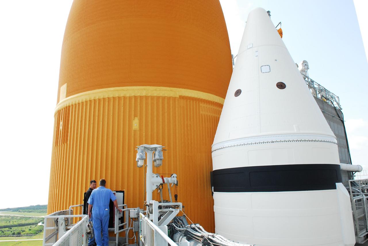
CAPE CANAVERAL, Fla. -- At NASA's Kennedy Space Center in Florida, technicians prepare to conduct Computed Radiography (CR) X-ray scans of 50 support beams, called stringers, on the shuttle-facing side of Atlantis' external tank at Launch Pad 39A. The hi-tech images will be taken of the tops and bottoms of the 21-foot long beams, which are located on the tank's intertank section. The scans follow a June 15th tanking test when the launch team filled then drained the tank of about 535,000 gallons of liquid hydrogen and liquid oxygen, just like for a launch. Earlier this year, managers directed teams to make the same stringer modifications to Atlantis' tank, ET-138, as they had after small cracks in the support beams of shuttle Discovery's STS-133 mission external tank were discovered. The scans will confirm there are no issues with Atlantis' tank. STS-135 Commander Chris Ferguson, Pilot Doug Hurley and Mission Specialists Sandy Magnus and Rex Walheim are targeted to lift off on space shuttle Atlantis July 8, taking with them the MPLM packed with supplies, logistics and spare parts to the International Space Station. The STS-135 mission also will fly a system to investigate the potential for robotically refueling existing satellites and return a failed ammonia pump module to help NASA better understand the failure mechanism and improve pump designs for future systems. STS-135 will be the 33rd flight of Atlantis, the 37th shuttle mission to the space station, and the 135th and final mission of NASA's Space Shuttle Program. For more information visit, www.nasa.gov/mission_pages/shuttle/shuttlemissions/sts135/index.html. Photo credit: NASA/Jim Grossmann

CAPE CANAVERAL, Fla. -- At NASA's Kennedy Space Center in Florida, technicians conduct Computed Radiography (CR) X-ray scans of 50 support beams, called stringers, on the shuttle-facing side of Atlantis' external tank at Launch Pad 39A. The hi-tech images will be taken of the tops and bottoms of the 21-foot long beams, which are located on the tank's intertank section. The scans follow a June 15th tanking test when the launch team filled then drained the tank of about 535,000 gallons of liquid hydrogen and liquid oxygen, just like for a launch. Earlier this year, managers directed teams to make the same stringer modifications to Atlantis' tank, ET-138, as they had after small cracks in the support beams of shuttle Discovery's STS-133 mission external tank were discovered. The scans will confirm there are no issues with Atlantis' tank. STS-135 Commander Chris Ferguson, Pilot Doug Hurley and Mission Specialists Sandy Magnus and Rex Walheim are targeted to lift off on space shuttle Atlantis July 8, taking with them the MPLM packed with supplies, logistics and spare parts to the International Space Station. The STS-135 mission also will fly a system to investigate the potential for robotically refueling existing satellites and return a failed ammonia pump module to help NASA better understand the failure mechanism and improve pump designs for future systems. STS-135 will be the 33rd flight of Atlantis, the 37th shuttle mission to the space station, and the 135th and final mission of NASA's Space Shuttle Program. For more information visit, www.nasa.gov/mission_pages/shuttle/shuttlemissions/sts135/index.html. Photo credit: NASA/Jim Grossmann
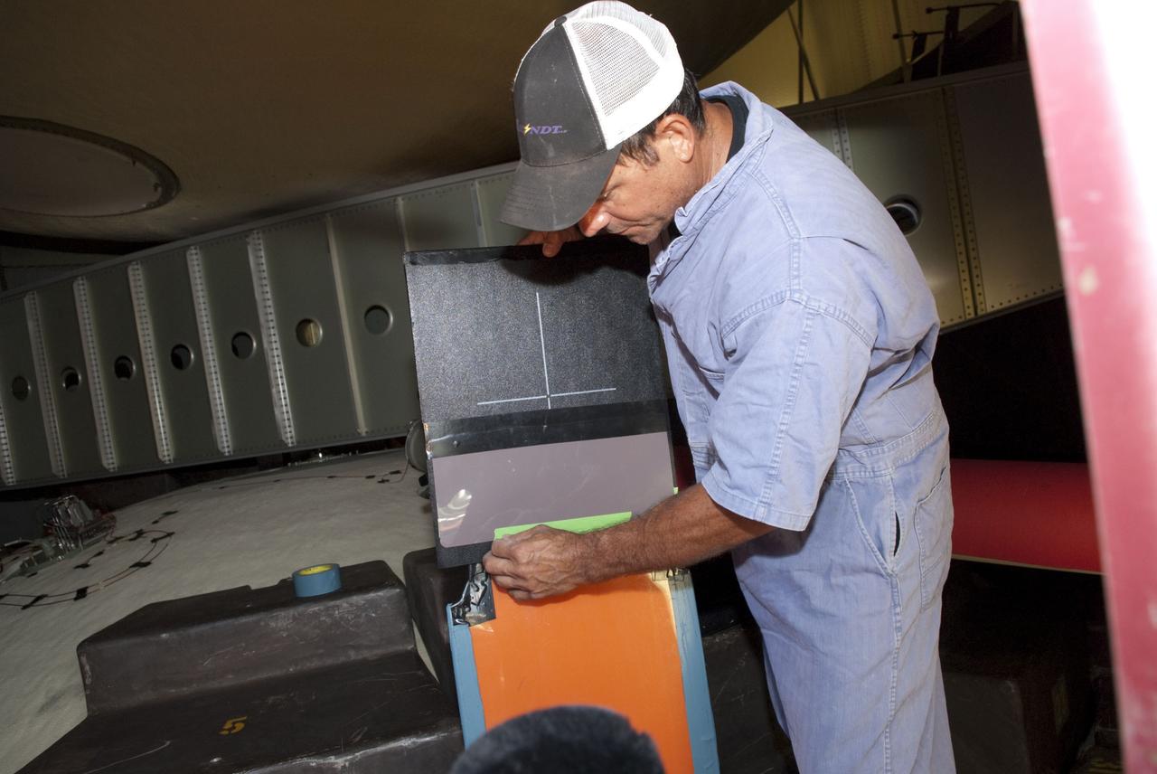
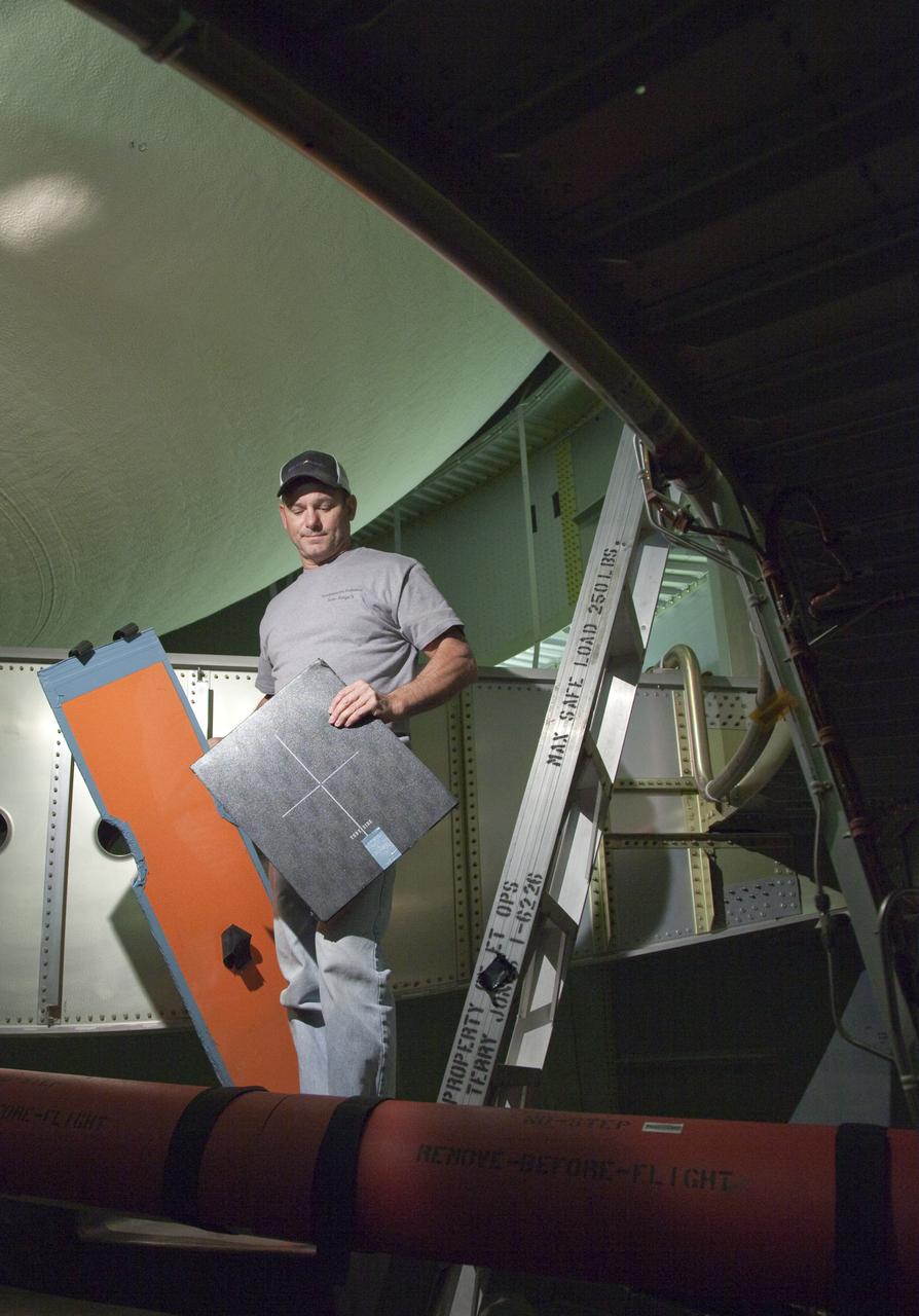
CAPE CANAVERAL, Fla. -- At NASA's Kennedy Space Center in Florida, technicians prepare to conduct Computed Radiography (CR) X-ray scans of 50 support beams, called stringers, on the shuttle-facing side of Atlantis' external tank at Launch Pad 39A. The hi-tech images will be taken of the tops and bottoms of the 21-foot long beams, which are located on the tank's intertank section. Here, a technician prepares an image plate inside the outertank. The scans follow a June 15th tanking test when the launch team filled then drained the tank of about 535,000 gallons of liquid hydrogen and liquid oxygen, just like for a launch. Earlier this year, managers directed teams to make the same stringer modifications to Atlantis' tank, ET-138, as they had after small cracks in the support beams of shuttle Discovery's STS-133 mission external tank were discovered. The scans will confirm there are no issues with Atlantis' tank. STS-135 Commander Chris Ferguson, Pilot Doug Hurley and Mission Specialists Sandy Magnus and Rex Walheim are targeted to lift off on space shuttle Atlantis July 8, taking with them the MPLM packed with supplies, logistics and spare parts to the International Space Station. The STS-135 mission also will fly a system to investigate the potential for robotically refueling existing satellites and return a failed ammonia pump module to help NASA better understand the failure mechanism and improve pump designs for future systems. STS-135 will be the 33rd flight of Atlantis, the 37th shuttle mission to the space station, and the 135th and final mission of NASA's Space Shuttle Program. For more information visit, www.nasa.gov/mission_pages/shuttle/shuttlemissions/sts135/index.html. Photo credit: NASA/Jim Grossmann
CAPE CANAVERAL, Fla. -- At NASA's Kennedy Space Center in Florida, technicians conduct Computed Radiography (CR) X-ray scans of 50 support beams, called stringers, on the shuttle-facing side of Atlantis' external tank at Launch Pad 39A. The hi-tech images will be taken of the tops and bottoms of the 21-foot long beams, which are located on the tank's intertank section. The scans follow a June 15th tanking test when the launch team filled then drained the tank of about 535,000 gallons of liquid hydrogen and liquid oxygen, just like for a launch. Earlier this year, managers directed teams to make the same stringer modifications to Atlantis' tank, ET-138, as they had after small cracks in the support beams of shuttle Discovery's STS-133 mission external tank were discovered. The scans will confirm there are no issues with Atlantis' tank. STS-135 Commander Chris Ferguson, Pilot Doug Hurley and Mission Specialists Sandy Magnus and Rex Walheim are targeted to lift off on space shuttle Atlantis July 8, taking with them the MPLM packed with supplies, logistics and spare parts to the International Space Station. The STS-135 mission also will fly a system to investigate the potential for robotically refueling existing satellites and return a failed ammonia pump module to help NASA better understand the failure mechanism and improve pump designs for future systems. STS-135 will be the 33rd flight of Atlantis, the 37th shuttle mission to the space station, and the 135th and final mission of NASA's Space Shuttle Program. For more information visit, www.nasa.gov/mission_pages/shuttle/shuttlemissions/sts135/index.html. Photo credit: NASA/Jim Grossmann
CAPE CANAVERAL, Fla. -- At NASA's Kennedy Space Center in Florida, technicians conduct Computed Radiography (CR) X-ray scans of 50 support beams, called stringers, on the shuttle-facing side of Atlantis' external tank at Launch Pad 39A. The hi-tech images will be taken of the tops and bottoms of the 21-foot long beams, which are located on the tank's intertank section. The scans follow a June 15th tanking test when the launch team filled then drained the tank of about 535,000 gallons of liquid hydrogen and liquid oxygen, just like for a launch. Earlier this year, managers directed teams to make the same stringer modifications to Atlantis' tank, ET-138, as they had after small cracks in the support beams of shuttle Discovery's STS-133 mission external tank were discovered. The scans will confirm there are no issues with Atlantis' tank. STS-135 Commander Chris Ferguson, Pilot Doug Hurley and Mission Specialists Sandy Magnus and Rex Walheim are targeted to lift off on space shuttle Atlantis July 8, taking with them the MPLM packed with supplies, logistics and spare parts to the International Space Station. The STS-135 mission also will fly a system to investigate the potential for robotically refueling existing satellites and return a failed ammonia pump module to help NASA better understand the failure mechanism and improve pump designs for future systems. STS-135 will be the 33rd flight of Atlantis, the 37th shuttle mission to the space station, and the 135th and final mission of NASA's Space Shuttle Program. For more information visit, www.nasa.gov/mission_pages/shuttle/shuttlemissions/sts135/index.html. Photo credit: NASA/Jim Grossmann
CAPE CANAVERAL, Fla. -- At NASA's Kennedy Space Center in Florida, technicians conduct Computed Radiography (CR) X-ray scans of 50 support beams, called stringers, on the shuttle-facing side of Atlantis' external tank at Launch Pad 39A. The hi-tech images will be taken of the tops and bottoms of the 21-foot long beams, which are located on the tank's intertank section. The scans follow a June 15th tanking test when the launch team filled then drained the tank of about 535,000 gallons of liquid hydrogen and liquid oxygen, just like for a launch. Earlier this year, managers directed teams to make the same stringer modifications to Atlantis' tank, ET-138, as they had after small cracks in the support beams of shuttle Discovery's STS-133 mission external tank were discovered. The scans will confirm there are no issues with Atlantis' tank. STS-135 Commander Chris Ferguson, Pilot Doug Hurley and Mission Specialists Sandy Magnus and Rex Walheim are targeted to lift off on space shuttle Atlantis July 8, taking with them the MPLM packed with supplies, logistics and spare parts to the International Space Station. The STS-135 mission also will fly a system to investigate the potential for robotically refueling existing satellites and return a failed ammonia pump module to help NASA better understand the failure mechanism and improve pump designs for future systems. STS-135 will be the 33rd flight of Atlantis, the 37th shuttle mission to the space station, and the 135th and final mission of NASA's Space Shuttle Program. For more information visit, www.nasa.gov/mission_pages/shuttle/shuttlemissions/sts135/index.html. Photo credit: NASA/Jim Grossmann
CAPE CANAVERAL, Fla. -- At NASA's Kennedy Space Center in Florida, technicians conduct Computed Radiography (CR) X-ray scans of 50 support beams, called stringers, on the shuttle-facing side of Atlantis' external tank at Launch Pad 39A. The hi-tech images will be taken of the tops and bottoms of the 21-foot long beams, which are located on the tank's intertank section. The scans follow a June 15th tanking test when the launch team filled then drained the tank of about 535,000 gallons of liquid hydrogen and liquid oxygen, just like for a launch. Earlier this year, managers directed teams to make the same stringer modifications to Atlantis' tank, ET-138, as they had after small cracks in the support beams of shuttle Discovery's STS-133 mission external tank were discovered. The scans will confirm there are no issues with Atlantis' tank. STS-135 Commander Chris Ferguson, Pilot Doug Hurley and Mission Specialists Sandy Magnus and Rex Walheim are targeted to lift off on space shuttle Atlantis July 8, taking with them the MPLM packed with supplies, logistics and spare parts to the International Space Station. The STS-135 mission also will fly a system to investigate the potential for robotically refueling existing satellites and return a failed ammonia pump module to help NASA better understand the failure mechanism and improve pump designs for future systems. STS-135 will be the 33rd flight of Atlantis, the 37th shuttle mission to the space station, and the 135th and final mission of NASA's Space Shuttle Program. For more information visit, www.nasa.gov/mission_pages/shuttle/shuttlemissions/sts135/index.html. Photo credit: NASA/Jim Grossmann

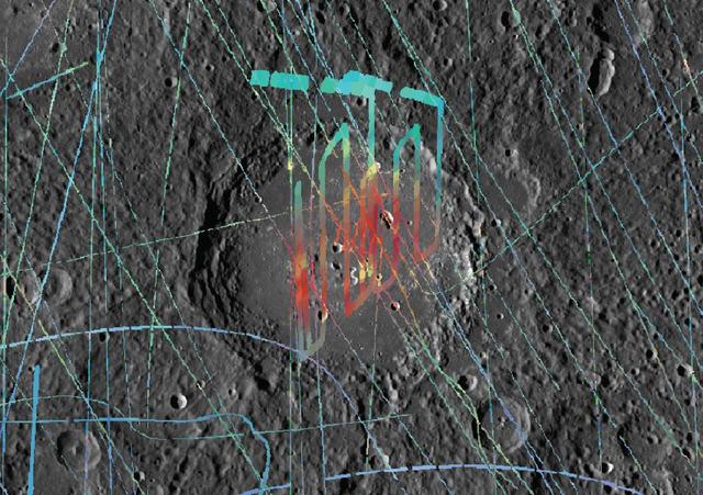
This video shows the SPHEREx observatory's field of view as it scans across a section of the sky, observing the universe in 102 colors, or wavelengths of light. Taken in April 2025, just weeks after the spacecraft's launch, the images show a region inside the Large Magellanic Cloud, a dwarf galaxy near the Milky Way. The wavelengths seen by NASA's SPHEREx (Spectro-Photometer for the History of the Universe, Epoch of Reionization and Ices Explorer) are in the infrared range, which is invisible to the human eye; the infrared wavelengths are represented here by visible light colors. While most telescopes use color filters that block one wavelength at a time, SPHEREx's filters gradually transition through a range of wavelengths, creating the rainbow gradients seen in this video. The telescope takes overlapping images so that every section of the sky is imaged 102 times, each time in a different wavelength. The color filters sit on top of two arrays, each with three detectors, that observe the sky simultaneously. In the video, one array's view moves from purple to green, followed by the second array's view (of the same section of sky), which changes from yellow to red. The images are looped four times. SPHEREx will repeat this scanning motion each day for two years, gradually compiling a map of the entire sky. Every day, it will take about 600 exposures, each of which is made up of six images, one from each of the six detectors. Combining those images, scientists can see the total emission from the observed section of the sky or look at an individual wavelength. Observing individual wavelengths of light from cosmic sources is called spectroscopy. This technique can be used to reveal the composition of objects, because chemical elements and molecules leave a unique signature in the colors they absorb and emit. This is made apparent in the images' lower right quadrant, where a collection of dust appears only in the red and orange wavelengths. This indicates the presence of a particular molecule that radiates in specific wavelengths and not others. Video available at https://photojournal.jpl.nasa.gov/catalog/PIA26351
Space Communications and Navigation, SCaN Quantum Metrology Lab
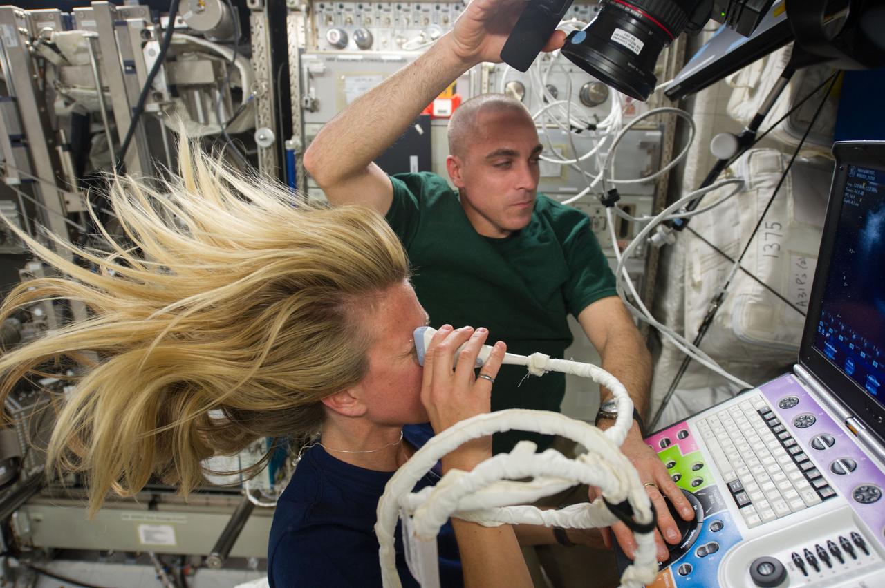
Astronaut Karen Nyberg,Expedition 37 flight engineer, assisted by astronaut Chris Cassidy, performs an Ocular Health (OH) Ultrasound 2 scan in the Destiny laboratory of the International Space Station.
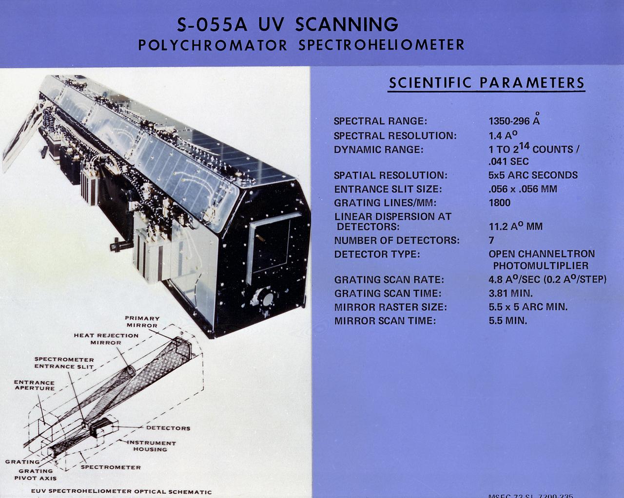
This chart describes scientific parameters of the Skylab Ultraviolet (UV) Scanning Polychromator Spectroheliometer, one the eight Apollo Telescope Mount facilities. It was designed to observe and provide temporal changes in UV radiation emitted by the Sun's chromosphere and lower corona. The Marshall Space Flight Center had program management responsibility for the development of skylab hardware and experiments.
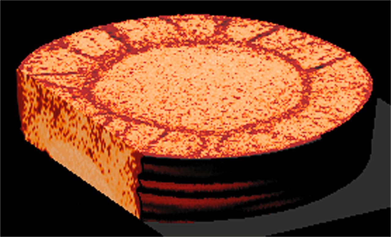
CT scans of the spcimens on STS-79 reveal internal cone-shaped features and radial patterns not seen in specimens processed on the ground. The lighter areas are the densest in these images. CT scans produced richly detailed images allowing scientists to build 3D models of the interior of the specimens that can be compared with microscopic examination of thin slices. This view is made from a series of horizontal slices. Sand and soil grains have faces that can cause friction as they roll and slide against each other, or even cause sticking and form small voids between grains. This complex behavior can cause soil to behave like a liquid under certain conditions such as earthquakes or when powders are handled in industrial processes. Mechanics of Granular Materials (MGM) experiments aboard the Space Shuttle use the microgravity of space to simulate this behavior under conditions that carnot be achieved in laboratory tests on Earth. MGM is shedding light on the behavior of fine-grain materials under low effective stresses. Applications include earthquake engineering, granular flow technologies (such as powder feed systems for pharmaceuticals and fertilizers), and terrestrial and planetary geology. Nine MGM specimens have flown on two Space Shuttle flights. Another three are scheduled to fly on STS-107. The principal investigator is Stein Sture of the University of Colorado at Boulder. Credit: Los Alamos National Laboratory and the University of Colorado at Boulder.
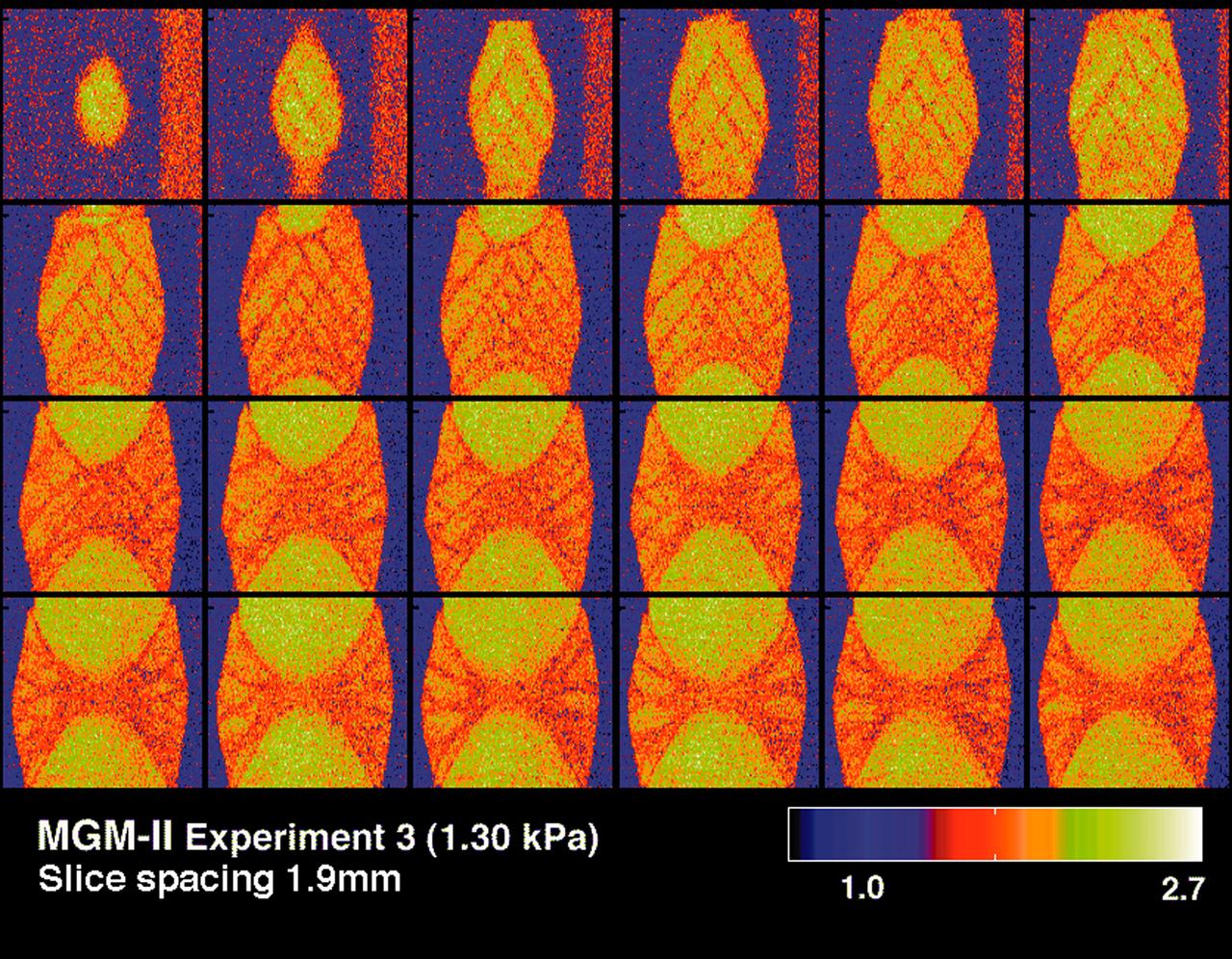
CT scans of the spcimens on STS-79 reveal internal cone-shaped features and radial patterns not seen in specimens processed on the ground. The lighter areas are the densest in these images. CT scans produced richly detailed images allowing scientists to build 3D models of the interior of the specimens that can be compared with microscopic examination of thin slices. These views depict vertical slices from side to middle of a flight specimen. Sand and soil grains have faces that can cause friction as they roll and slide against each other, or even cause sticking and form small voids between grains. This complex behavior can cause soil to behave like a liquid under certain conditions such as earthquakes or when powders are handled in industrial processes. Mechanics of Granular Materials (MGM) experiments aboard the Space Shuttle use the microgravity of space to simulate this behavior under conditions that carnot be achieved in laboratory tests on Earth. MGM is shedding light on the behavior of fine-grain materials under low effective stresses. Applications include earthquake engineering, granular flow technologies (such as powder feed systems for pharmaceuticals and fertilizers), and terrestrial and planetary geology. Nine MGM specimens have flown on two Space Shuttle flights. Another three are scheduled to fly on STS-107. The principal investigator is Stein Sture of the University of Colorado at Boulder. Credit: Los Alamos National Laboratory and the University of Colorado at Boulder.
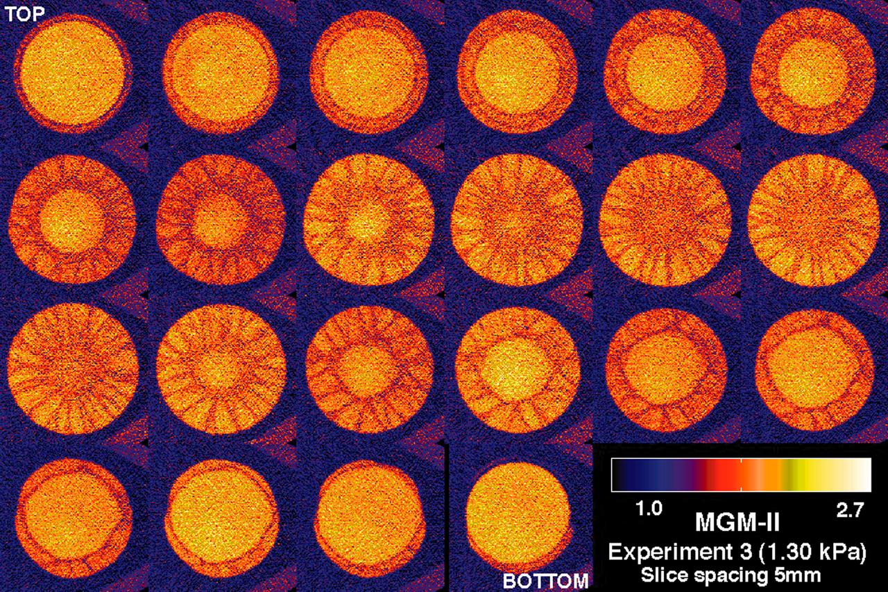
CT scans of the spcimens on STS-79 reveal internal cone-shaped features and radial patterns not seen in specimens processed on the ground. The lighter areas are the densest in these images. CT scans produced richly detailed images allowing scientists to build 3D models of the interior of the specimens that can be compared with microscopic examination of thin slices. This view depict horizontal slices from top to bottom of a flight specimen. Sand and soil grains have faces that can cause friction as they roll and slide against each other, or even cause sticking and form small voids between grains. This complex behavior can cause soil to behave like a liquid under certain conditions such as earthquakes or when powders are handled in industrial processes. Mechanics of Granular Materials (MGM) experiments aboard the Space Shuttle use the microgravity of space to simulate this behavior under conditions that carnot be achieved in laboratory tests on Earth. MGM is shedding light on the behavior of fine-grain materials under low effective stresses. Applications include earthquake engineering, granular flow technologies (such as powder feed systems for pharmaceuticals and fertilizers), and terrestrial and planetary geology. Nine MGM specimens have flown on two Space Shuttle flights. Another three are scheduled to fly on STS-107. The principal investigator is Stein Sture of the University of Colorado at Boulder. Credit: Los Alamos National Laboratory and the University of Colorado at Boulder.
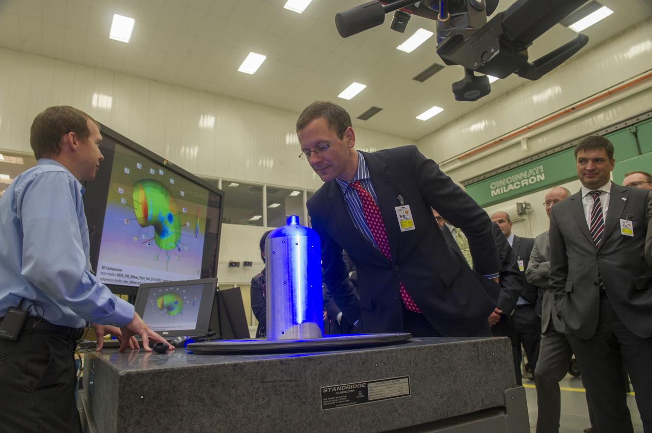
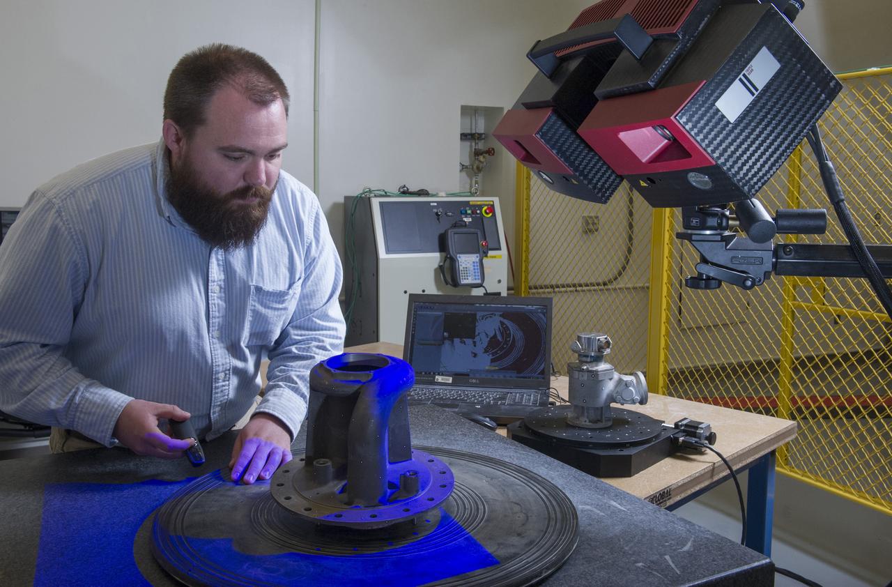
MSFC MECHANICAL ENGINEER BRIAN WEST, (L), DEMONSTRATES STRUCTURED LIGHT SCANNING PROCESS TO MEMBERS OF THE BREMEN, GERMANY, BUSINESS DELEGATION WHO VISITED MARSHALL RECENTLY. SENATOR MARTIN GÜNTHNER, MINISTRY OF ECONOMIC AFFAIRS, LABOUR AND PORTS (CENTER) VIEWS THE PRESSURE VESSEL BEING SCANNED. AT RIGHT IS BERND SCHMELING, SENIOR MANAGER PROCUREMENT, AIRBUS OPERATIONS GMBH
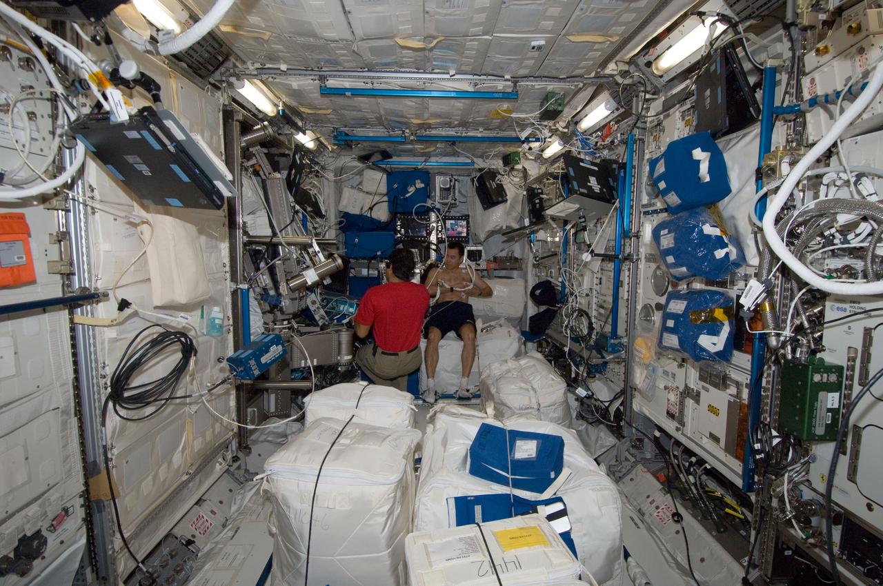
ISS030-E-155938 (20 Jan. 2012) --- NASA astronaut Dan Burbank, Expedition 30 commander, sets up the Integrated Cardiovascular (ICV) Resting Echo Scan at the Human Research Facility (HRF) rack in the Columbus laboratory of the International Space Station.
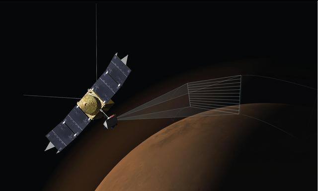
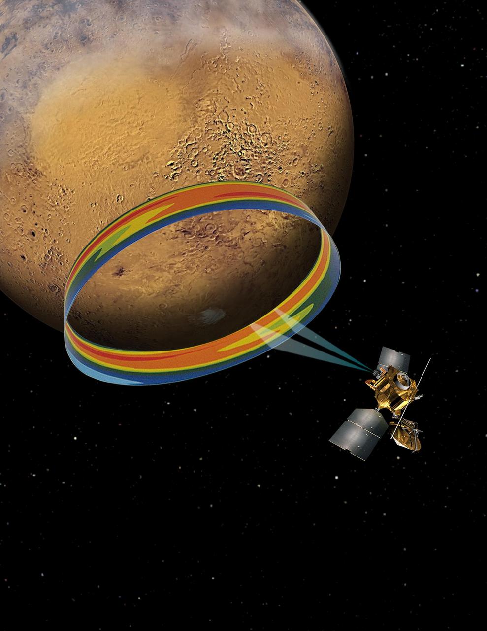
This artist concept depicts the Imaging Ultraviolet Spectrograph IUVS on NASA MAVEN spacecraft scanning the upper atmosphere of Mars. IUVS uses limb scans to map the chemical makeup and vertical structure across Mars upper atmosphere.
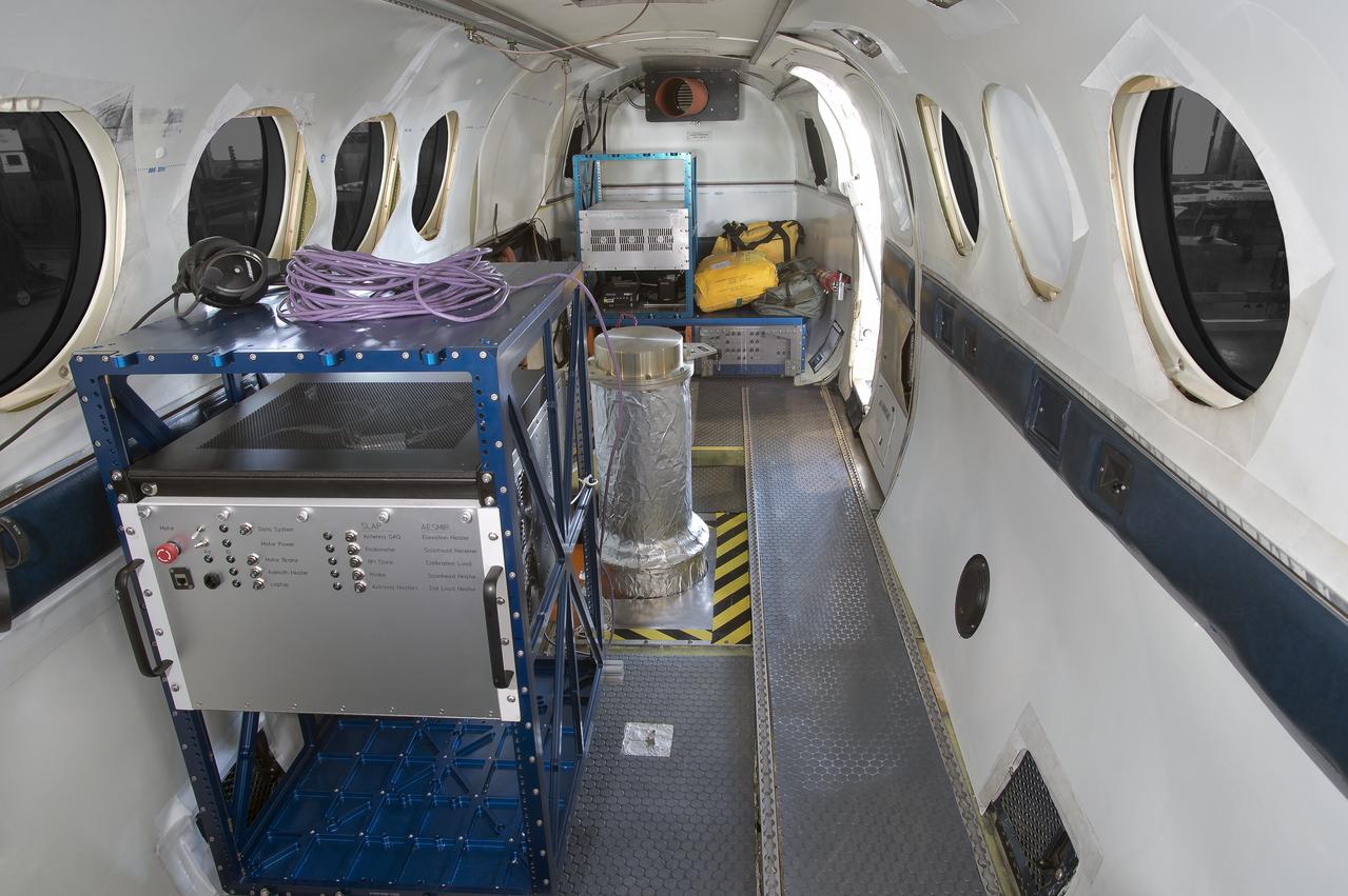
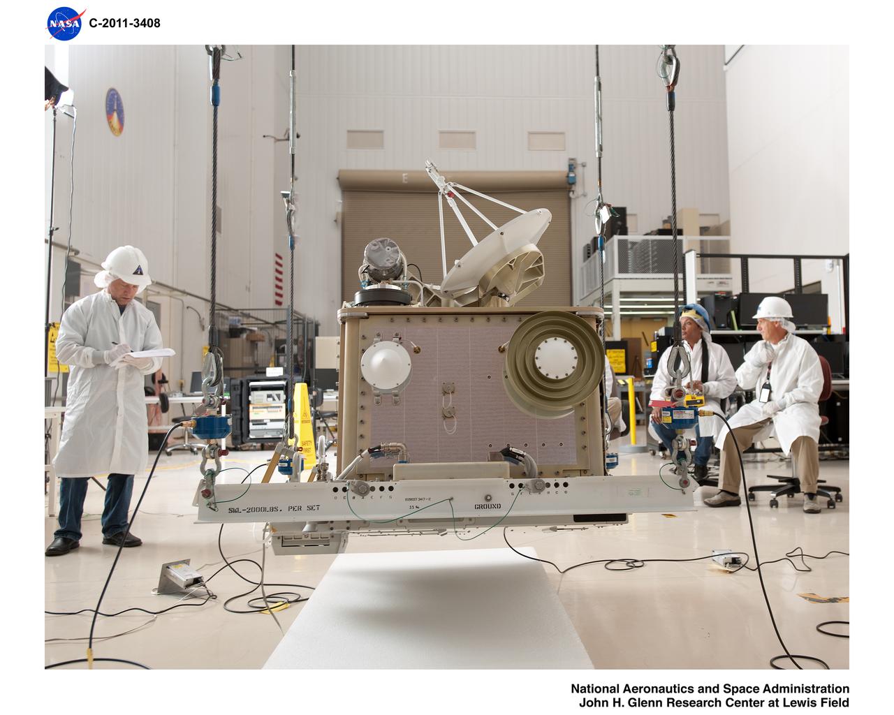
Forward Welch rack, SLAP instrument and aft Welch rack; view looking aft
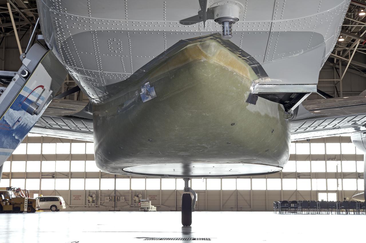
antenna and external fairing mounted on UC-12B; view looking forward
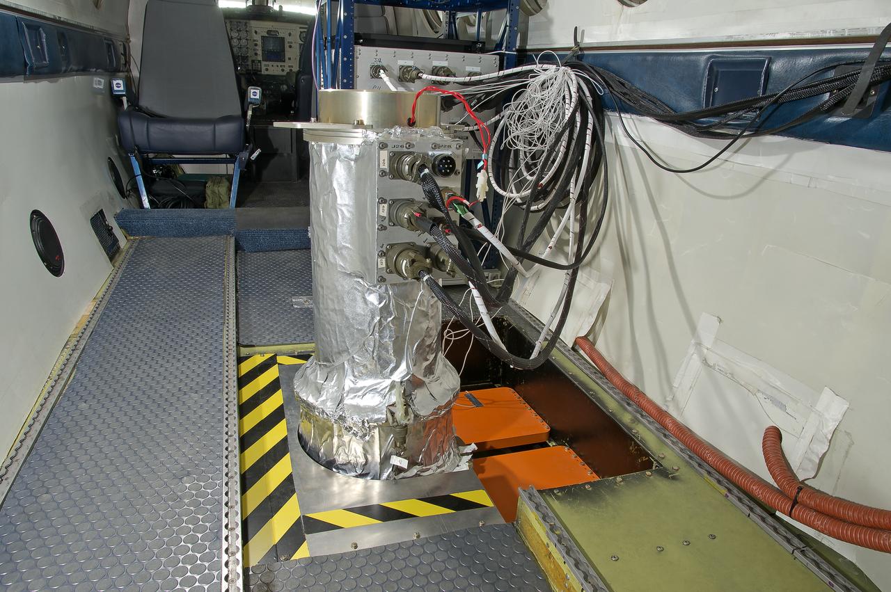
SLAP instrument installed in forward nadir portal; view looking forward
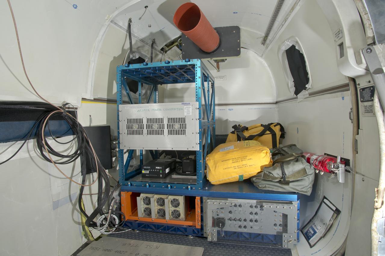
power converter and Applanix unit installed in Welch rack; Welch rack mounted on aft riser
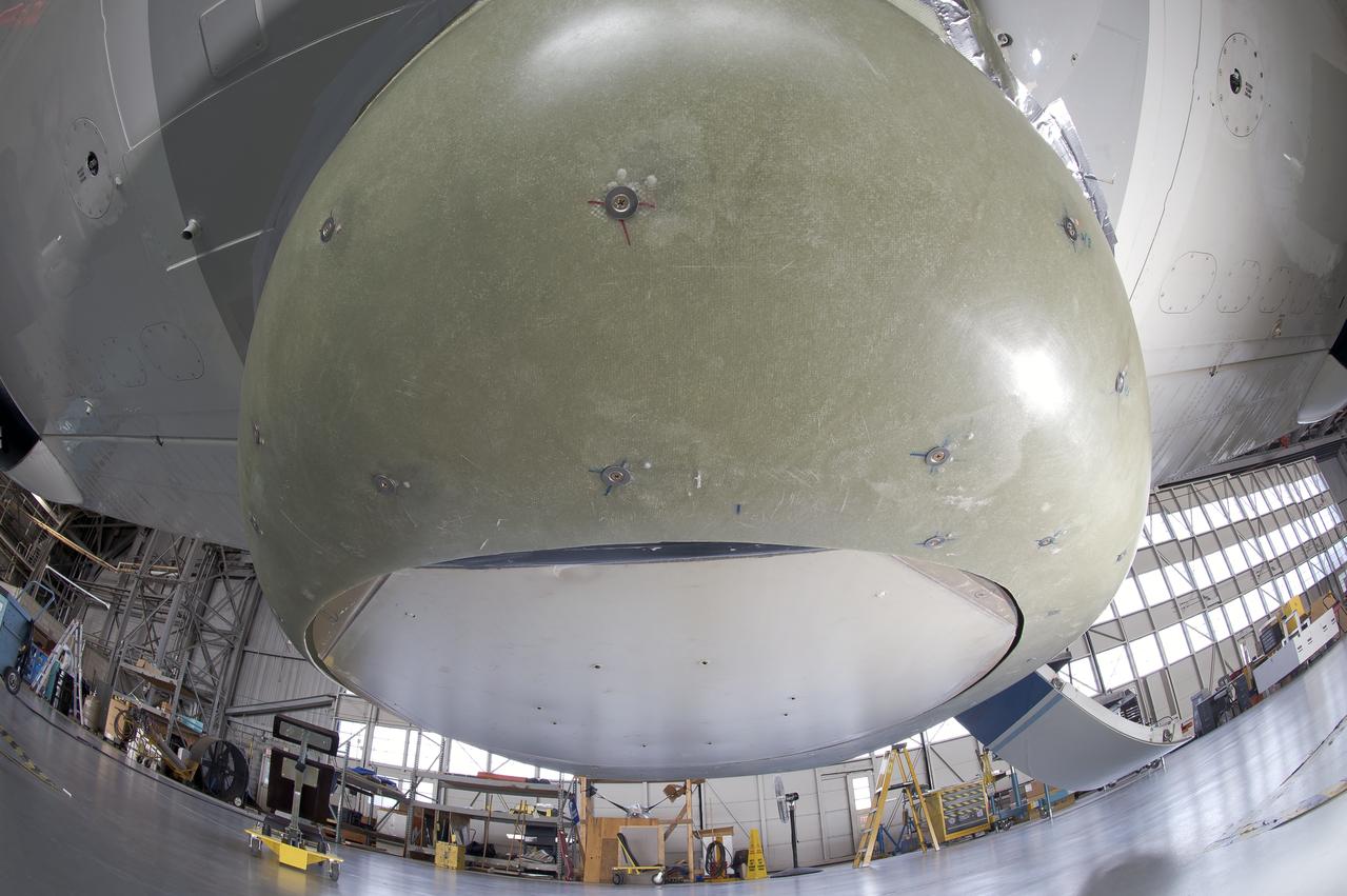
SLAP antenna and external fairing mounted on UC-12B; view looking aft
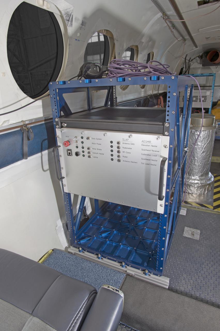
SLAP control unit installed in forward Welch rack; view looking aft
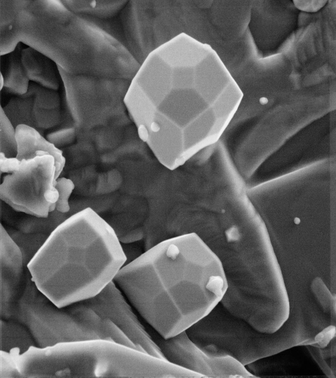
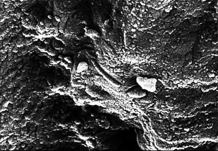
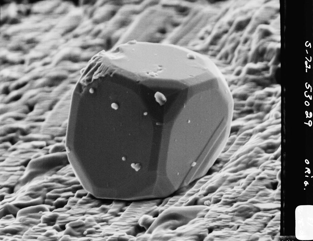
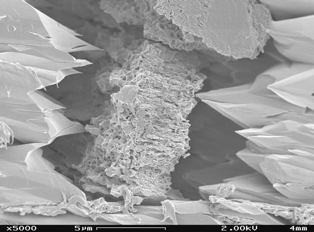
A scanning electron microscope photograph of iron crystals which grow in a small vug or cavity in a recrystallized breccia (fragmented rock) from the Apollo 15 Hadley-Apennino lunar landing site. The largest crystal is three microns across. Perfectly developed crystals such as these indicate slow formation from a hot vapor as the rock was cooling. The crystals are resting on an interlocking lattice of pyroxene (calsium-magnesium-iron silicate).
ISS032-E-011853 (1 Aug. 2012) --- NASA astronaut Joe Acaba (left) and Japan Aerospace Exploration Agency astronaut Aki Hoshide, both Expedition 32 flight engineers, perform an Integrated Cardiovascular (ICV) Resting Echo Scan at the Human Research Facility (HRF) rack in the Columbus laboratory of the International Space Station.
ISS030-E-155942 (20 Jan. 2012) --- NASA astronaut Dan Burbank, Expedition 30 commander, prepares to use the Integrated Cardiovascular (ICV) Resting Echo Scan on a crew member (out of frame) at the Human Research Facility (HRF) rack in the Columbus laboratory of the International Space Station.
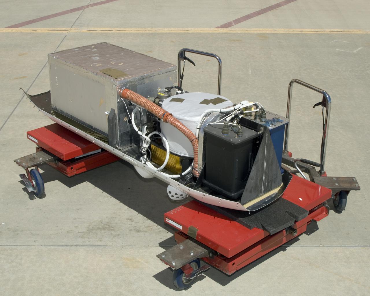
The instruments that make up the Ames Autonomous Module Scanner (AMS) that provided precise thermal-infrared imaging during the Western States Fire Mission in 2007 are detailed in this photo of the AMS as mounted on Ikhana's pod tray. The large foil-covered foam-insulated box at left covers the pressure vessel containing the data system computers and other electronics. The round white-topped assembly is the scan head, including the scan mirror, folded telescope, blackbody references, spectrometer and detectors. Two pressure boxes visible at the forward end of the tray contain the Applanix POS/AV precision navigation subsystem (black) and the power distributor including circuit breakers and ancillary wiring, scan motor controller and the blackbody reference temperature controller (blue).
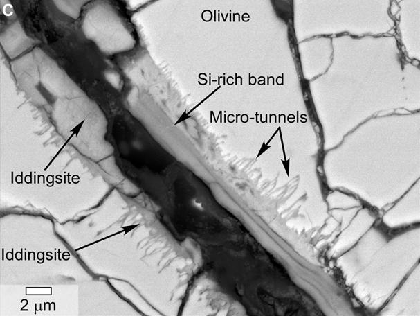
This scanning electron microscope image of a polished thin section of a meteorite from Mars shows tunnels and curved microtunnels.
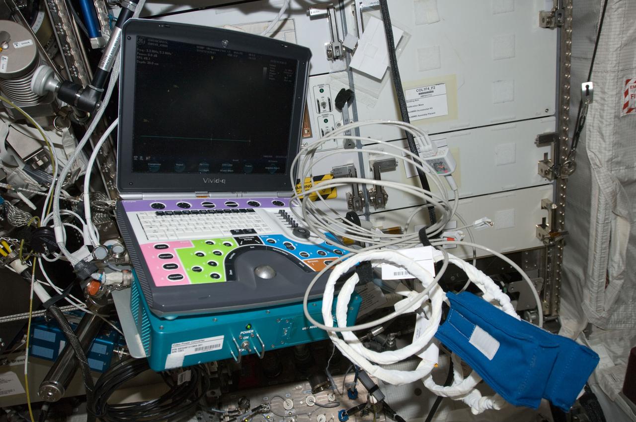
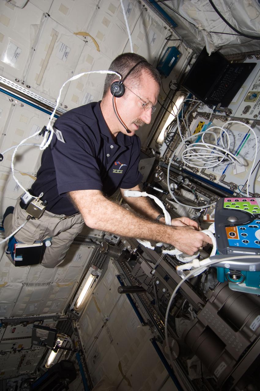
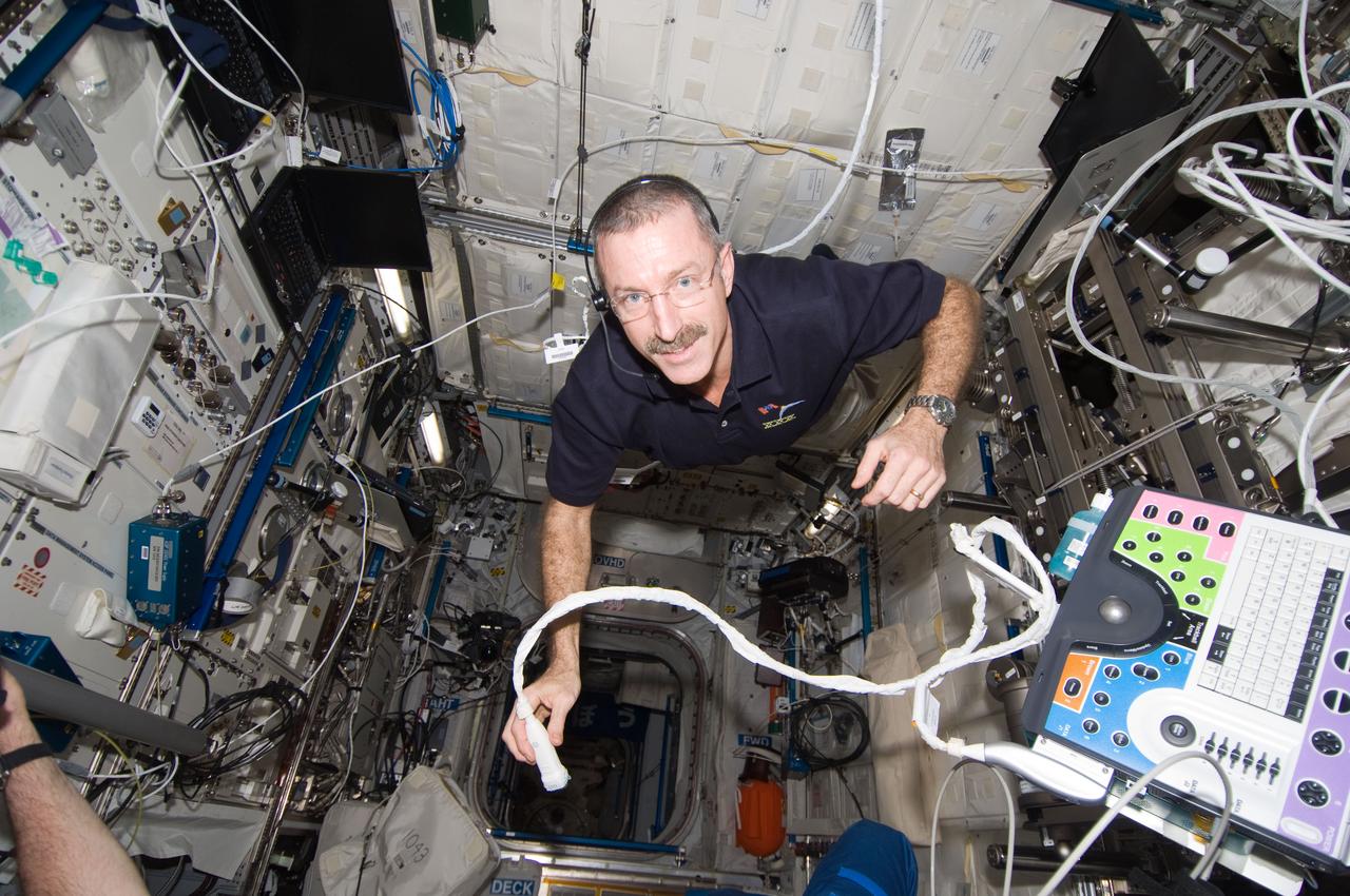
ISS029-E-025270 (3 Oct. 2011) --- NASA astronaut Mike Fossum, Expedition 29 commander, performs a SPRINT leg muscle self scan in the Columbus laboratory of the International Space Station. Fossum powered on the Ultrasound 2 (USND-2) unit and Video Power Converter (VPC) hardware, and connected the VPC to Human Research Facility 1 (HRF-1) in order to perform this activity.
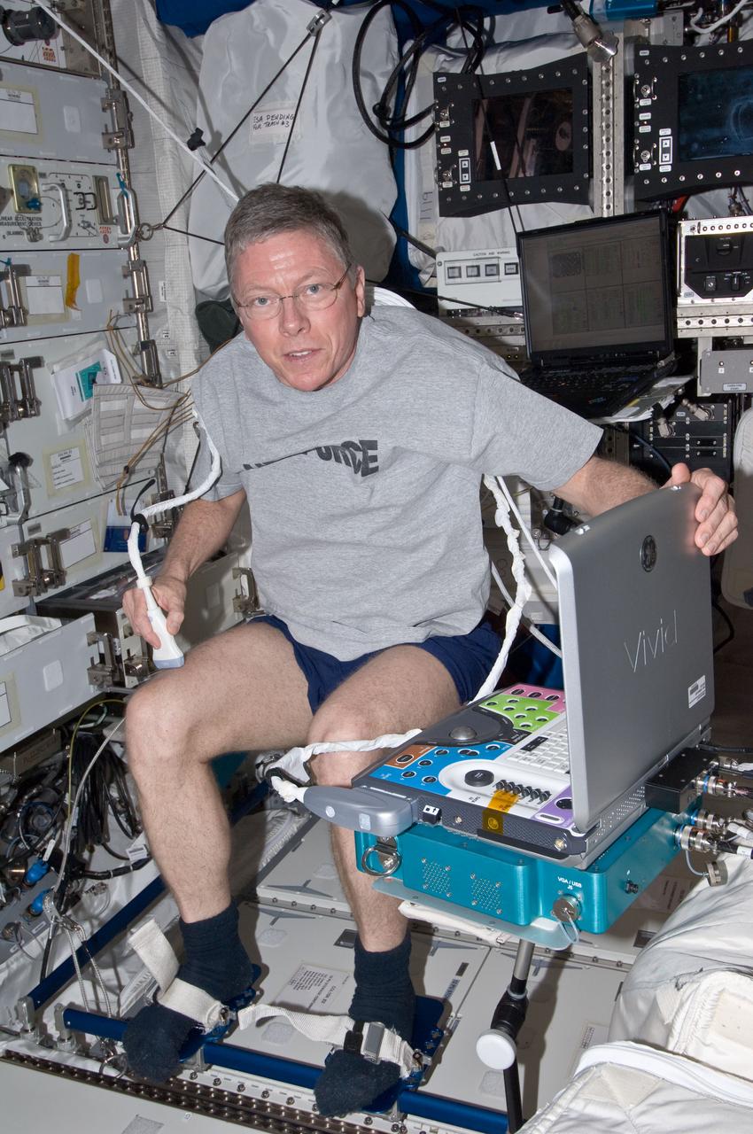
ISS029-E-025280 (3 Oct. 2011) --- NASA astronaut Mike Fossum, Expedition 29 commander, performs a SPRINT leg muscle self scan in the Columbus laboratory of the International Space Station. Fossum powered on the Ultrasound 2 (USND-2) unit and Video Power Converter (VPC) hardware, and connected the VPC to Human Research Facility 1 (HRF-1) in order to perform this activity.
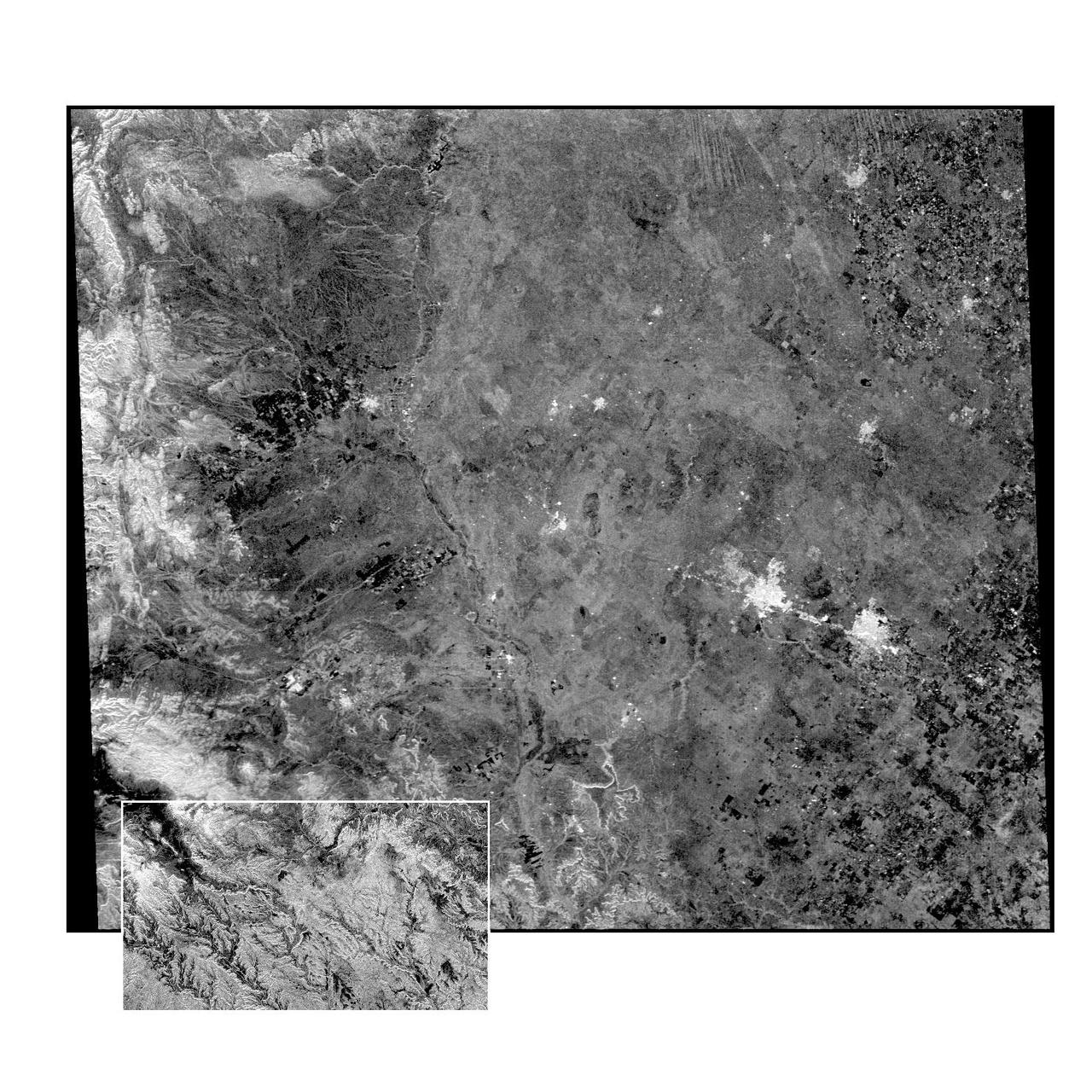
This radar image of the Midland/Odessa region of West Texas, demonstrates an experimental technique, called ScanSAR, that allows scientists to rapidly image large areas of the Earth's surface. The large image covers an area 245 kilometers by 225 kilometers (152 miles by 139 miles). It was obtained by the Spaceborne Imaging Radar-C/X-Band Synthetic Aperture Radar (SIR-C/X-SAR) flying aboard the space shuttle Endeavour on October 5, 1994. The smaller inset image is a standard SIR-C image showing a portion of the same area, 100 kilometers by 57 kilometers (62 miles by 35 miles) and was taken during the first flight of SIR-C on April 14, 1994. The bright spots on the right side of the image are the cities of Odessa (left) and Midland (right), Texas. The Pecos River runs from the top center to the bottom center of the image. Along the left side of the image are, from top to bottom, parts of the Guadalupe, Davis and Santiago Mountains. North is toward the upper right. Unlike conventional radar imaging, in which a radar continuously illuminates a single ground swath as the space shuttle passes over the terrain, a Scansar radar illuminates several adjacent ground swaths almost simultaneously, by "scanning" the radar beam across a large area in a rapid sequence. The adjacent swaths, typically about 50 km (31 miles) wide, are then merged during ground processing to produce a single large scene. Illumination for this L-band scene is from the top of the image. The beams were scanned from the top of the scene to the bottom, as the shuttle flew from left to right. This scene was acquired in about 30 seconds. A normal SIR-C image is acquired in about 13 seconds. The ScanSAR mode will likely be used on future radar sensors to construct regional and possibly global radar images and topographic maps. The ScanSAR processor is being designed for 1996 implementation at NASA's Alaska SAR Facility, located at the University of Alaska Fairbanks, and will produce digital images from the forthcoming Canadian RADARSAT satellite. http://photojournal.jpl.nasa.gov/catalog/PIA01787
This scanning electron microscope image shows speroidal features embedded in a layer of iddingsite, a mineral formed by action of water, in a meteorite that came from Mars.
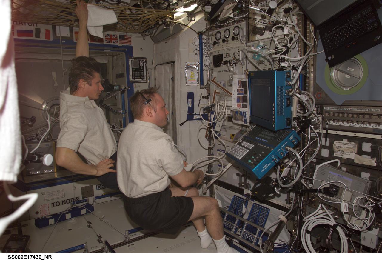
ISS009-E-17439 (10 August 2004) --- Astronaut Edward M. (Mike) Fincke (foreground), Expedition 9 NASA ISS science officer and flight engineer, performs an ultrasound bone scan on cosmonaut Gennady I. Padalka, commander representing Russia's Federal Space Agency. The two are using the Advanced Diagnostic Ultrasound in Micro-G (ADUM) in the Destiny laboratory of the International Space Station (ISS). The ADUM keyboard, flat screen display and front control panel are visible at right.
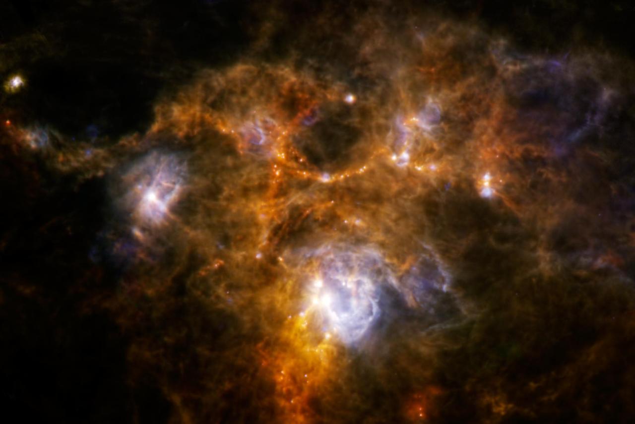
The Herschel Space Observatory has uncovered a weird ring of dusty material while obtaining one of the sharpest scans to date of a huge cloud of gas and dust, called NGC 7538.
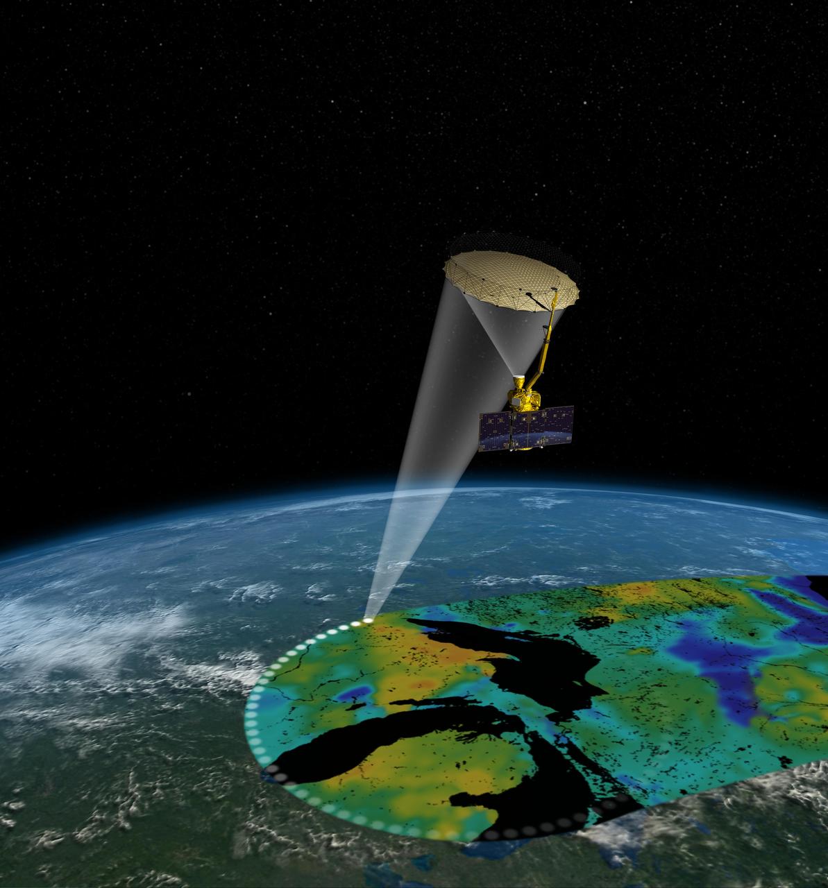
Artist rendering of the Soil Moisture Active Passive SMAP satellite. The width of the region scanned on Earth surface during each orbit is about 620 miles 1,000 kilometers.
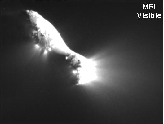
Infrared scans of comet Hartley 2 by NASA EPOXI mission spacecraft show carbon dioxide, dust, and ice being distributed in a similar way and emanating from apparently the same locations on the nucleus.
This image, created at the Jet Propulsion Laboratory JPL, shows the Soil Moisture Active Passive SMAP mission, specifically depicting how the scanning antenna will fly in space and the swath coverage over the Earth.
Shuttle Scan 3-D technology
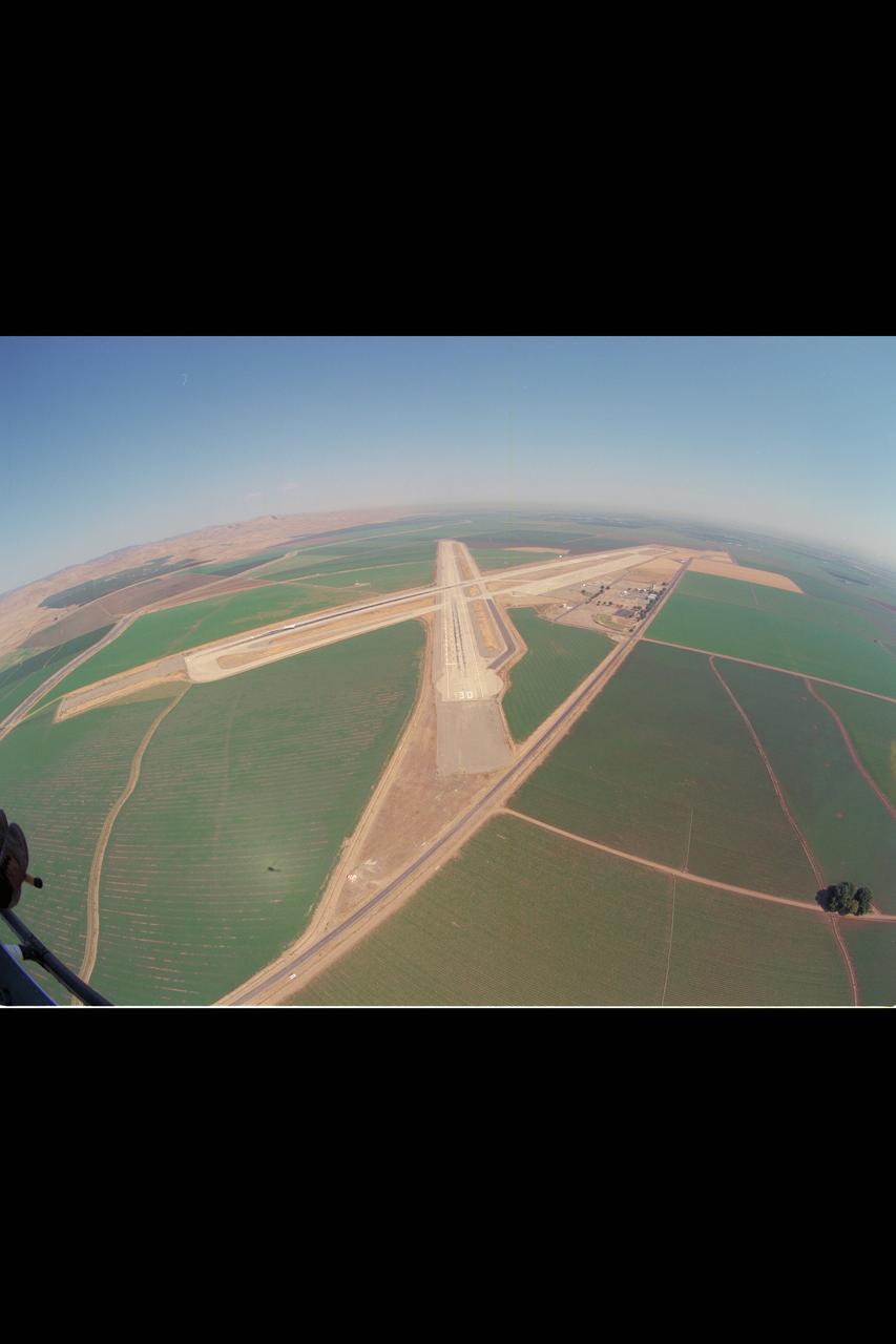
Crows Landing runway approach (scanning the horizon)

jsc2024e016244 (11/27/2023) --- The final Multi-Resolution Scanning payload docked with an Astrobee robot at NASA’s Ames Research Center. The Multi-Resolution Scanning payload uses multiple different sensor types to generate high-resolution 3D data and more accurate trajectory data to understand how the robot moves around in 3D space. Such systems could support future Gateway and Lunar surface missions by providing automated defect detection, automated and remote maintenance, autonomous vehicle operations, and surface scanning using rovers.
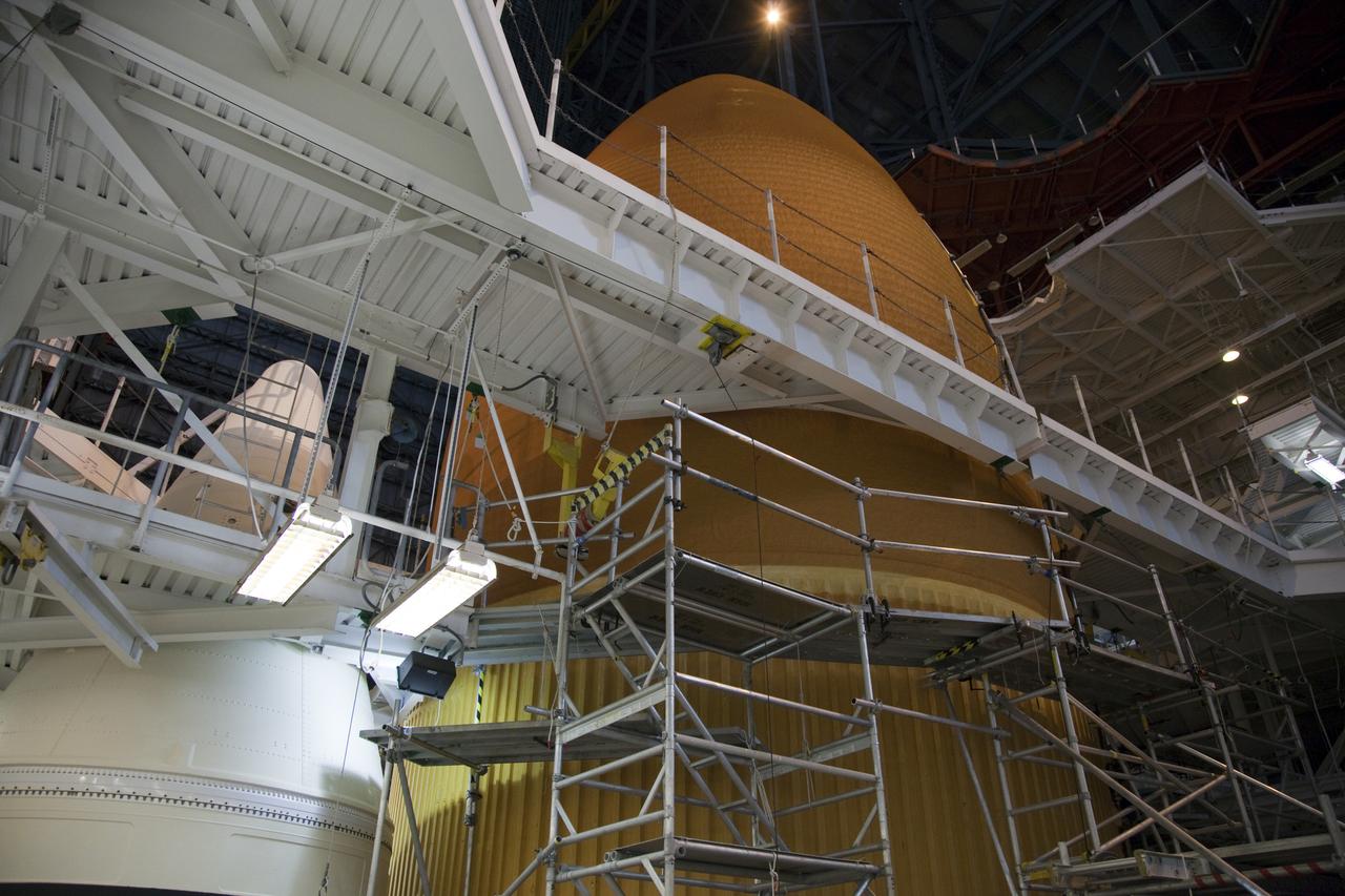
STS-133 Discovery X-ray scans ET-137 in VAB
STS-133 Discovery X-ray scans ET-137 in VAB
STS-133 Discovery X-ray scans ET-137 in VAB

STS-133 Discovery X-ray scans ET-137 in VAB
STS-133 Discovery X-ray scans ET-137 in VAB
STS-133 Discovery X-ray scans ET-137 in VAB
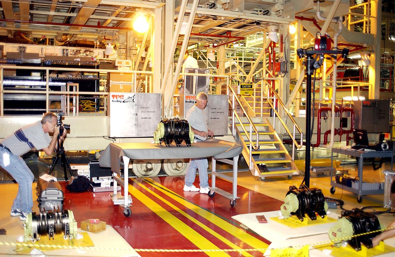
KENNEDY SPACE CENTER, FLA. - In the Orbiter Processing Facility, an actuator is set up on a table for a 3D digital scan. There are two actuators per engine on the Shuttle, one for pitch motion and one for yaw motion. The Space Shuttle Main Engine hydraulic servoactuators are used to gimbal the main engine.
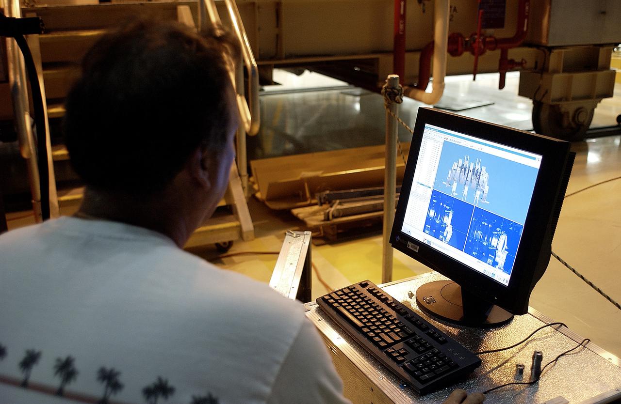
KENNEDY SPACE CENTER, FLA. - In the Orbiter Processing Facility, Boeing worker Alden Pitard looks at a 3D digital scan of an actuator. There are two actuators per engine on the Shuttle, one for pitch motion and one for yaw motion. The Space Shuttle Main Engine hydraulic servoactuators are used to gimbal the main engine.

KENNEDY SPACE CENTER, FLA. - In the Orbiter Processing Facility, the nose cap from Atlantis is lowered toward a shipping pallet. The reinforced carbon-carbon (RCC) nose cap is being sent to the original manufacturing company, Vought in Ft. Worth, Texas, a subsidiary of Lockheed Martin, to undergo non-destructive testing such as CAT scan and thermography.
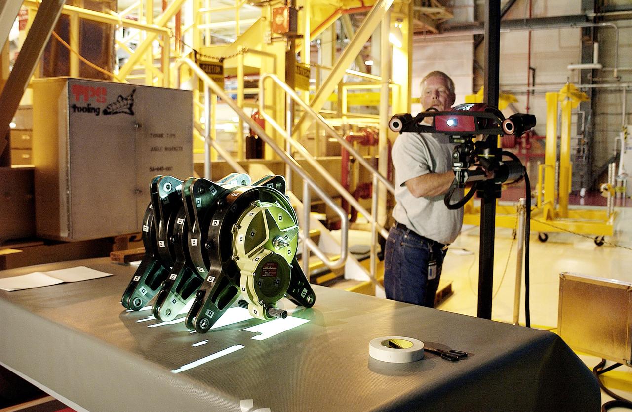
KENNEDY SPACE CENTER, FLA. - In the Orbiter Processing Facility, Dan Clark, with KSC Boeing, operates the camera for a 3D digital scan of the actuator on the table. There are two actuators per engine on the Shuttle, one for pitch motion and one for yaw motion. The Space Shuttle Main Engine hydraulic servoactuators are used to gimbal the main engine.
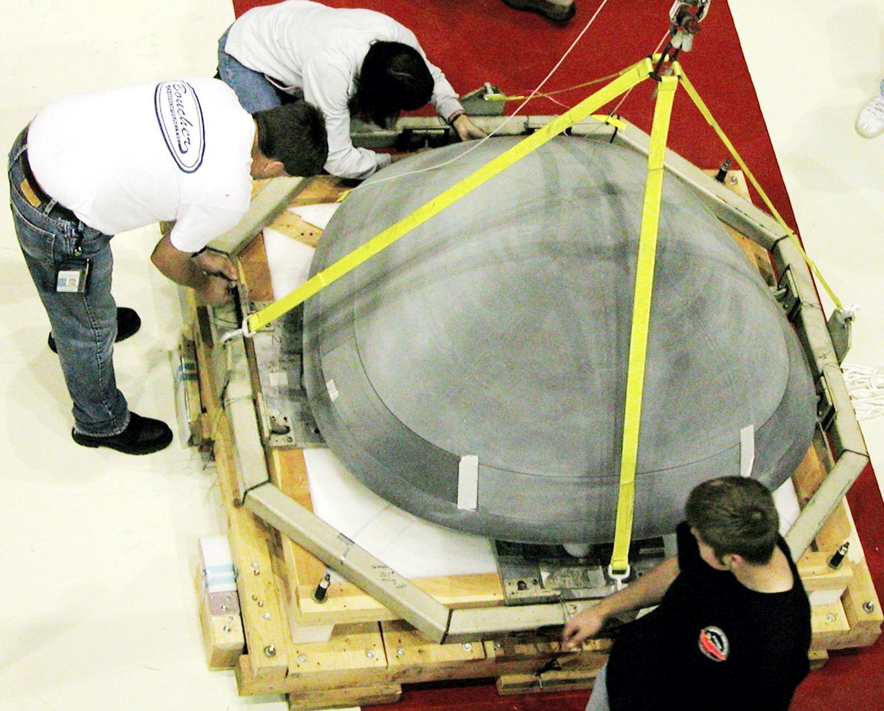
KENNEDY SPACE CENTER, FLA. - In the Orbiter Processing Facility, the nose cap from Atlantis is secured on a shipping pallet. The reinforced carbon-carbon (RCC) nose cap is being sent to the original manufacturing company, Vought in Ft. Worth, Texas, a subsidiary of Lockheed Martin, to undergo non-destructive testing such as CAT scan and thermography.
This high-resolution scanning electron microscope image shows an unusual tube-like structural form that is less than 1/100th the width of a human hair in size found in meteorite ALH84001, a meteorite believed to be of Martian origin. http://photojournal.jpl.nasa.gov/catalog/PIA00288
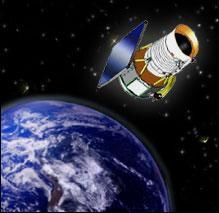
Artist concept of Wide-field Infrared Survey Explorer. A new NASA mission will scan the entire sky in infrared light in search of nearby cool stars, planetary construction zones and the brightest galaxies in the universe. http://photojournal.jpl.nasa.gov/catalog/PIA06927

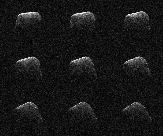
This image shows asteroids observed so far by NASA Wide-field Infrared Survey Explorer. An animation is available at the Photojournal.

NASA Cassini spacecraft surveys the surface of Saturn moon Enceladus in this image, which shows newly created terrain in the upper right meeting older, cratered terrain in the lower left.

A nighttime shot shows some of the antennas of the Owens Valley Long Wavelength Array in California, with the center of our galaxy in the background. A video can be seen at https://www.youtube.com/watch?v=vXvHqyOaJrU&feature=youtu.be. http://photojournal.jpl.nasa.gov/catalog/PIA19336 Copyright: Gregg Hallinan

This approximately true-color image shows paper-thin layers of light-toned, jagged-edged rocks; a light gray rock with smooth, rounded edges atop and drifts; and several dark gray to black, angular rocks with vesicles typical of hardened lava

New insights into the nature of Saturn’s rings are revealed in this panoramic mosaic of 15 images taken during the planet’s August 2009 equinox, taken by NASA Cassini Orbiter.
These radar images of comet P/2016 BA14 were taken on March 22, 2016, by scientists using an antenna of NASA Deep Space Network at Goldstone, CA. At the time, the comet was about 2.2 million miles 3.6 million kilometers from Earth.
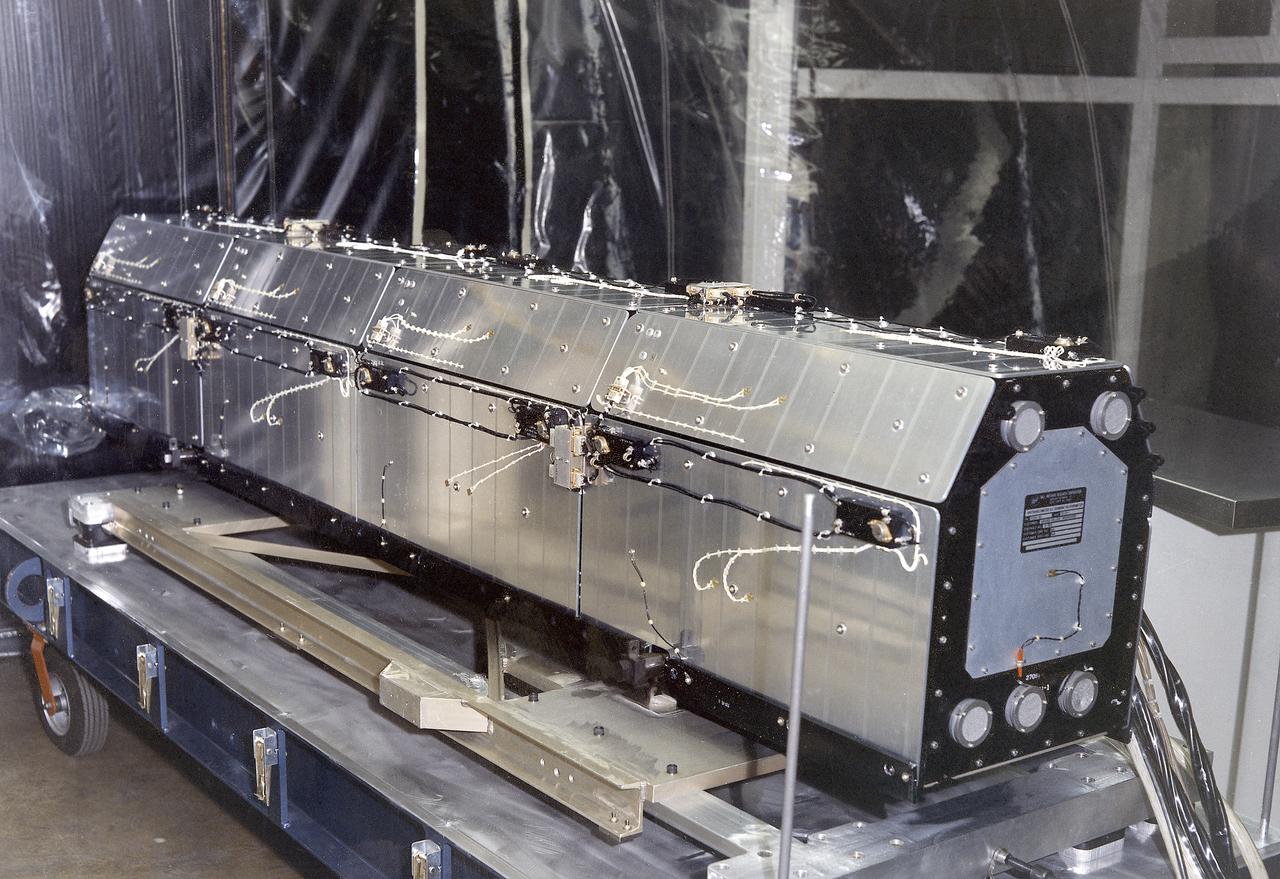
This 1970 photograph shows the flight unit for Skylab's Ultraviolet (UV) Scarning Polychromator Spectroheliometer, an Apollo Telescope Mount (ATM) facility. It was designed to observe temporal changes in UV radiation emitted by the Sun's chromosphere and lower corona. The Marshall Space Flight Center had program management responsibility for the development of Skylab hardware and experiments.
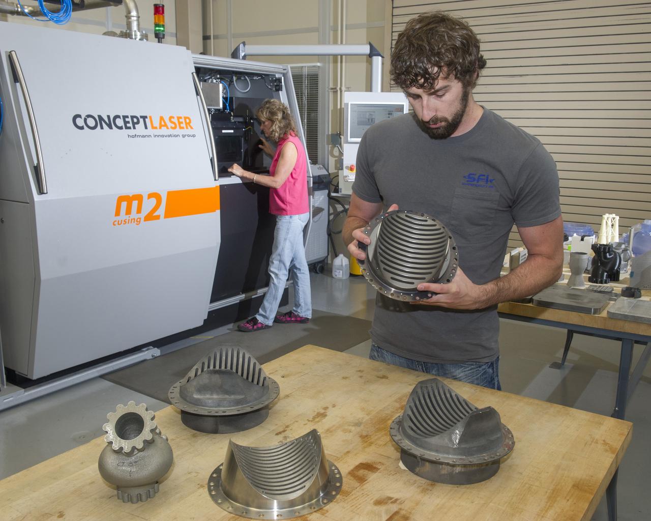
JOHN IVESTER PERFORMING STRUCTURED LIGHT SCANNING OF HERITAGE HARDWARE TO CAPTURE THE AS-BUILT GEOMETRY.
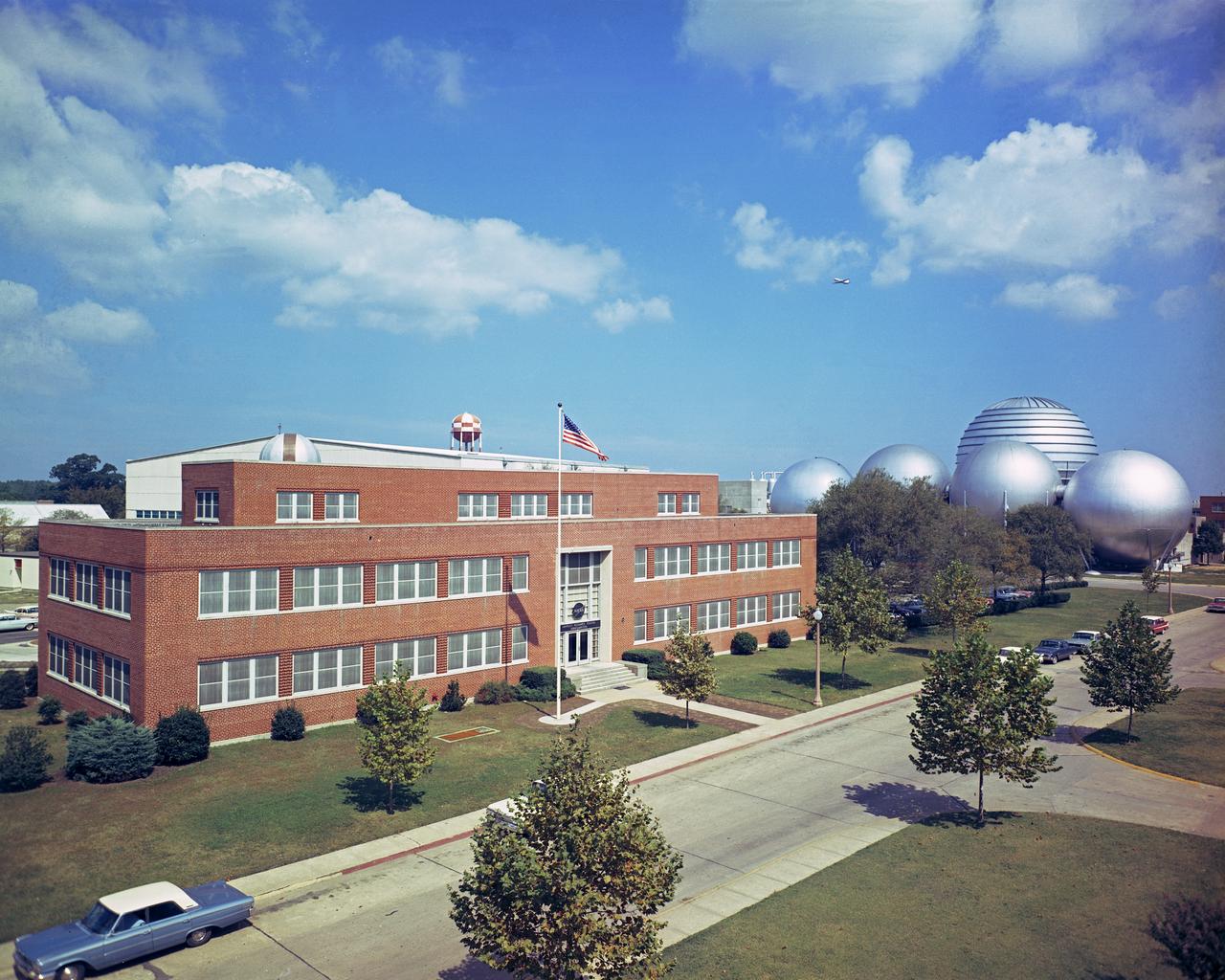
Headquarters building and spheres at Gas Dynamics. DAO Section. Scanned on 4/23/2018.
BRENT COLE, EM 42 STRUCTURED LIGHT SCANNING LEAD IN MSFC 3D PRINTING FACILITY
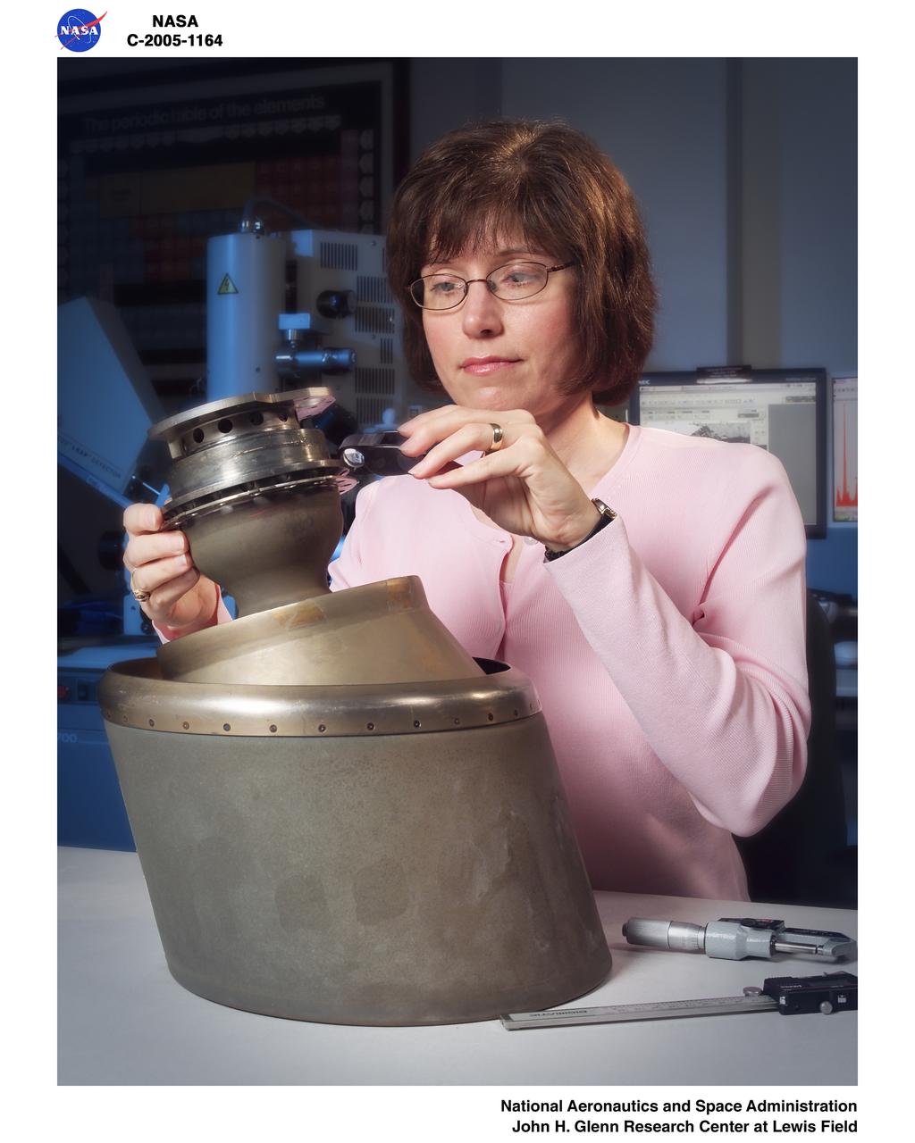
Reaction Control System Thruster examined in the electron optics lab Near Field Emission Scanning Electron Microscope
PHOTOMICROPHOTOGRAPHY -GEOLOGY (SEM) High magnification and resolution views of lunar, meteorite and terrestrial materials with the Scanning Electron Microscope (SEM).
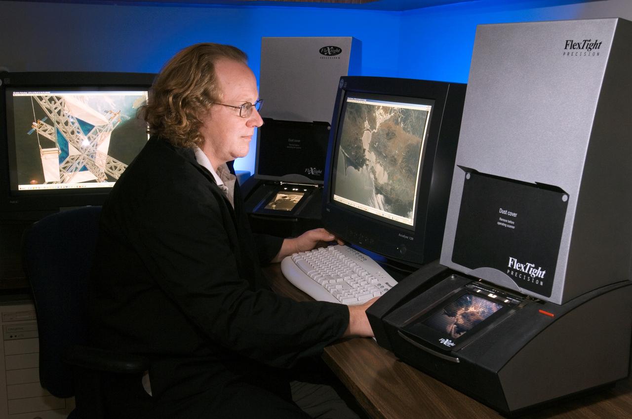
View of Larry Jefferson in the Building 8 photo lab scanning area working with Environmental Photos.
Communications, Navigation, and Network Reconfigurable Test-bed, CoNNeCT, Gravity Test on the Space Communications and Navigation, SCaN, Testbed

Modeling Simulation and Analysis, National Aeronautics and Space Administration, NASA, Space Communications and Navigation, SCaN, SCENIC Laboratory
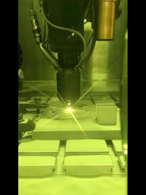
This video clip shows a 3D printing technique where a printer head scans over each layer of a part, blowing metal powder that is melted by a laser. It's one of several ways parts are 3D printed at NASA's Jet Propulsion Laboratory, but was not used to create the parts aboard the Perseverance rover. Movie available at https://photojournal.jpl.nasa.gov/catalog/PIA23972

KENNEDY SPACE CENTER, FLA. - A great blue heron is captured in a typical pose as it scans the nearby water in NASA Kennedy Space Center’s Turn Basin for food.

jsc2024e016240 (3/20/2023) --- The multi-resolution scanning payload prototype housed within an Astrobee robot at NASA’s Ames Research Center (with front cover removed). The Multi-Resolution Scanning payload will be mated to the Astrobee free-flying robot, which will undertake a small flight and use the multi-resolution scanner (MRS) to create 3D maps of the interior of the International Space Station. Image courtesy of CSIRO.
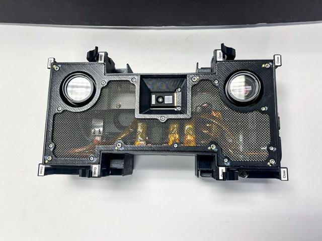
jsc2024e016243 (2/14/2024) --- Close-up view of the final Multi-Resolution Scanning payload with its stereo vision cameras at left and right. The Multi-Resolution Scanning payload uses multiple different sensor types to generate high-resolution 3D data and more accurate trajectory data to understand how the Astrobee robot moves around in 3D space.
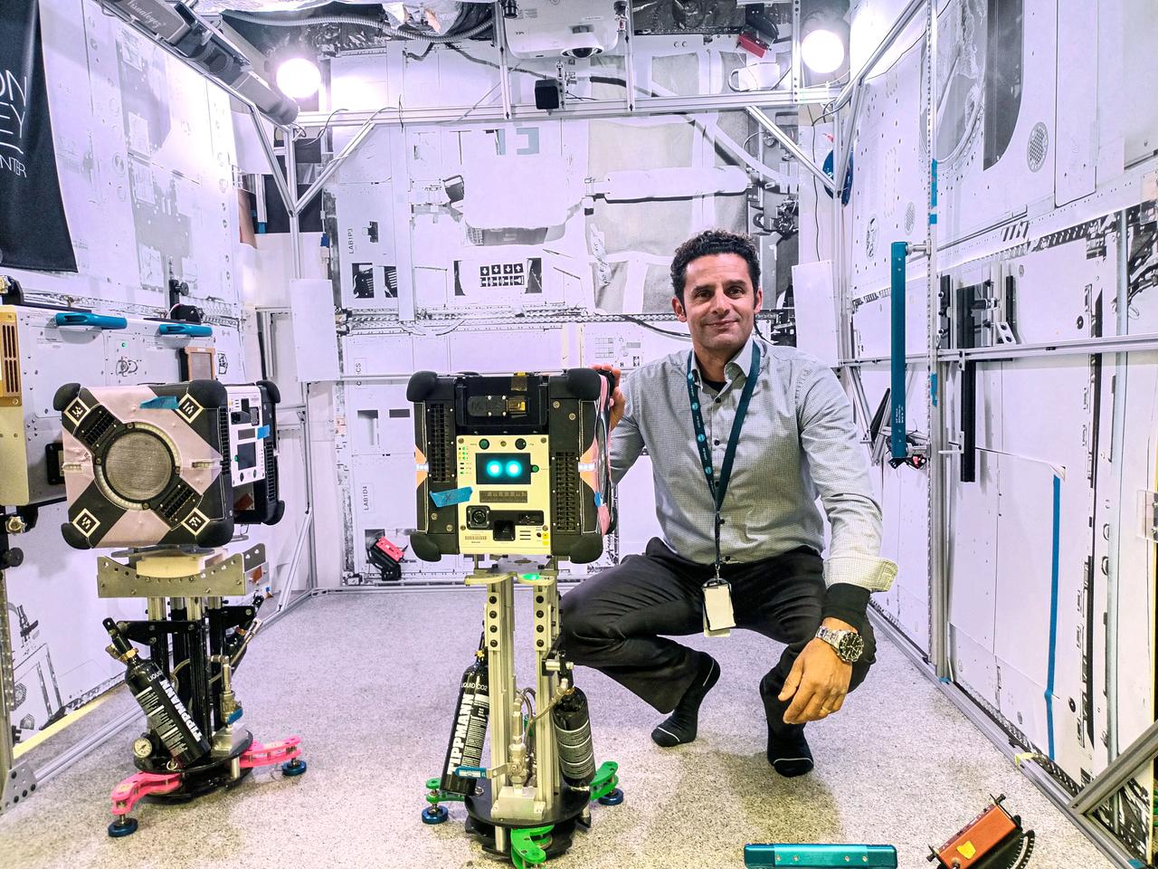
jsc2024e016241 (11/17/2023) --- CSIRO Project Lead Dr. Marc Elmouttie with the Multi-Resolution Scanning payload, housed.within an Astrobee robot. The Multi-Resolution Scanning payload uses multiple different sensor types to generate high-resolution 3D data and more accurate trajectory data to understand how the robot moves around in 3D space. Image courtesy of CSIRO.
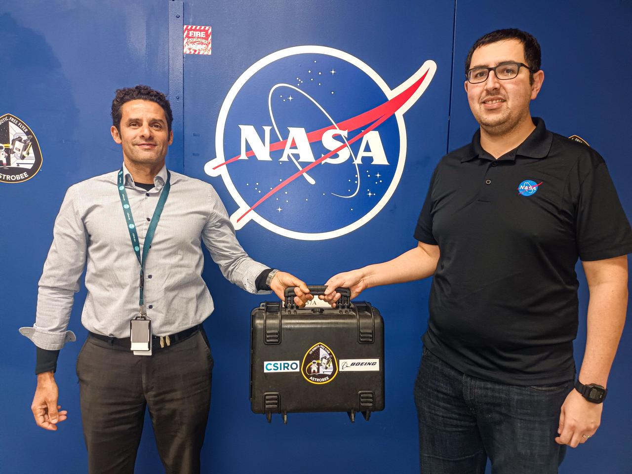
jsc2024e016242 (11/17/2023) --- CSIRO Project Lead Dr. Marc Elmouttie hands over the flight-ready Multi-Resolution Scanning payload to Jose Cortez from NASA’s Ames Research Center ahead of its final testing. The Multi-Resolution Scanning payload will be mated to the Astrobee free-flying robot, which will undertake a small flight and use the multi-resolution scanner (MRS) to create 3D maps of the interior of the International Space Station. Image courtesy of CSIRO.

This colorized mosaic from NASA Cassini mission shows an infrared view of the Saturn system, backlit by the sun, from July 19, 2013.

These images from NASA Terra satellite images of Oklahoma and north Texas were acquired on March 12, 2000 during Terra orbit 1243.
This animation shows the data collected on a Mars 2020 sample tube using a computerized tomography (CT) scanner. Engineers working on the sample tubes used the 3D imagery to better understand the tubes' internal structure. About the size and shape of a standard lab test tube, the 43 sample tubes headed to Mars must be lightweight, hardy enough to survive the demands of the round trip, and so clean that future scientists will be confident that what they are analyzing is 100% Mars. Movie available at https://photojournal.jpl.nasa.gov/catalog/PIA24304

ISS038-E-007119 (21 Nov. 2013) --- Japan Aerospace Exploration Agency astronaut Koichi Wakata, Expedition 38 flight engineer, wears ultrasound gear around his legs while performing the Integrated Resistance and Aerobic Training Study (Sprint) experiment in the Columbus laboratory of the International Space Station. Sprint evaluates the use of high intensity, low volume exercise training to minimize loss of muscle, bone, and cardiovascular function in station crew members during long-duration missions.
This graphic depicts the Mars Climate Sounder instrument on NASA Mars Reconnaissance Orbiter measuring the temperature of a cross section of the Martian atmosphere as the orbiter passes above the south polar region.
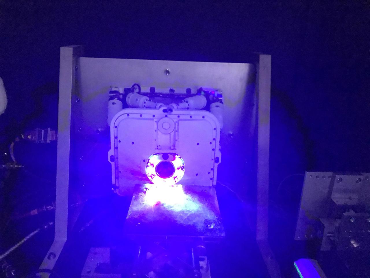
The Planetary Instrument for X-ray Lithochemistry (PIXL), one of seven instruments aboard NASA's Perseverance Mars rover, requires pictures of rock targets to autonomously position itself. Because PIXL works at night, it is equipped with light diodes circling its opening to take pictures of rock targets in the dark. Using artificial intelligence, PIXL relies on the images to determine how far away it is from a target to be scanned. https://photojournal.jpl.nasa.gov/catalog/PIA24095

CAPE CANAVERAL, Fla. – During a news conference at NASA's Kennedy Space Center in Florida, agency and contractor officials discussed preparations for the launch of NASA's Tracking and Data Relay Satellite, or TDRS-L, spacecraft. Participants included Badri Younes, deputy associate administrator, Space Communications and Navigation SCaN NASA Human Exploration and Operations Mission Directorate at NASA Headquarters in Washington D.C. The TDRS-L spacecraft is the second of three new satellites designed to ensure vital operational continuity for NASA by expanding the lifespan of the Tracking and Data Relay Satellite System TDRSS fleet, which consists of eight satellites in geosynchronous orbit. The spacecraft provide tracking, telemetry, command and high bandwidth data return services for numerous science and human exploration missions orbiting Earth. These include NASA's Hubble Space Telescope and the International Space Station. TDRS-L has a high-performance solar panel designed for more spacecraft power to meet the growing S-band communications requirements. TDRSS is one of NASA Space Communication and Navigation’s SCaN three networks providing space communications to NASA’s missions. For more information more about TDRS-L, visit: http://www.nasa.gov/tdrs To learn more about SCaN, visit: www.nasa.gov/scan Photo credit: NASA/Frankie Martin
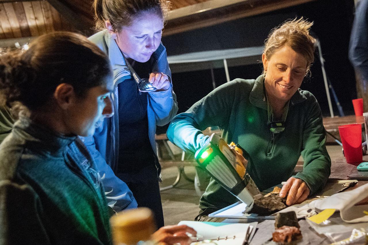
jsc2019e055001 (09-16-19) --- 2017 NASA astronaut candidate Loral O’Hara scans her sample during data collection during geology training in Arizona. Photo Credit: (NASA/Bill Stafford)
A scanning electron microscope captured this image of terresterial soil containing a phyllosilicate mineral from Koua Bocca, Ivory Coast, West Africa. This soil shares some similarities with Martian soil scooped by NASA Phoenix Lander.
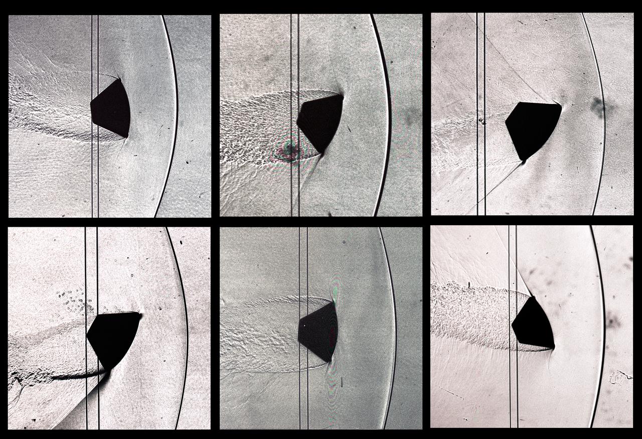
CEV (Crew Escape Vehicle) capsule Balistic Range testing to examine static and dynamic stability characteristics (at the Hypervelocity Free-Flight Facility) HFF - scans of shadowgraphs from 8x10 film images
Ground crewman at NASA’s Armstrong Flight Research Center in Palmdale, CA install a rail to support the Autonomous, Robotic Telescope Mount Instrument Subsystem, which is part of air-LUSI and has a camera that scans the sky to find the Moon.
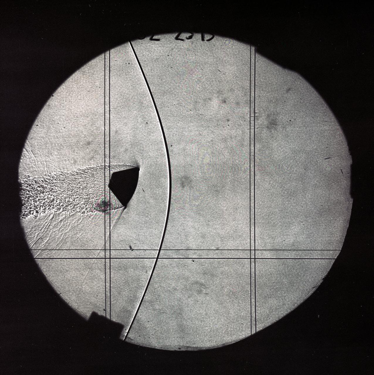
CEV (Crew Escape Vehicle) capsule Balistic Range testing to examine static and dynamic stability characteristics (at the Hypervelocity Free-Flight Facility) HFF - scans of shadowgraphs from 8x10 film images
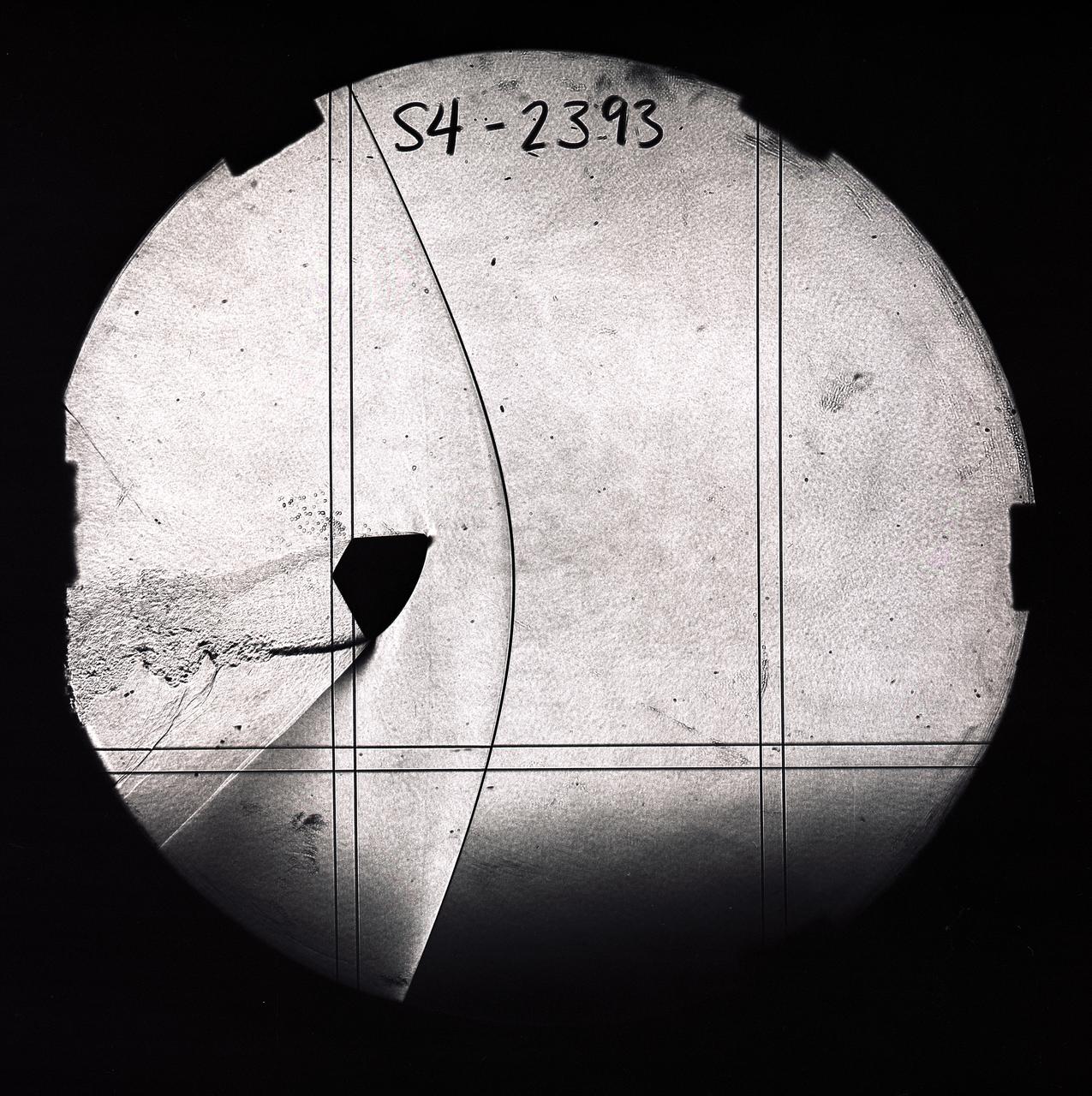
CEV (Crew Escape Vehicle) capsule Balistic Range testing to examine static and dynamic stability characteristics (at the Hypervelocity Free-Flight Facility) HFF - scans of shadowgraphs from 8x10 film images

CEV (Crew Escape Vehicle) capsule Balistic Range testing to examine static and dynamic stability characteristics (at the Hypervelocity Free-Flight Facility) HFF - scans of shadowgraphs from 8x10 film images
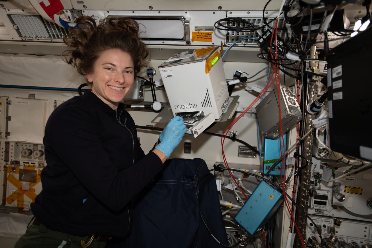
iss066e110569 (Jan. 10, 2022) --- NASA astronaut and Expedition 66 Flight Engineer Kayla Barron sets up and installs the Mochii electron-scanning microscope that can be used to identify trace particles aboard the International Space Station.
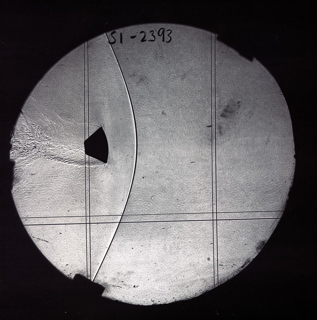
CEV (Crew Escape Vehicle) capsule Balistic Range testing to examine static and dynamic stability characteristics (at the Hypervelocity Free-Flight Facility) HFF - scans of shadowgraphs from 8x10 film images