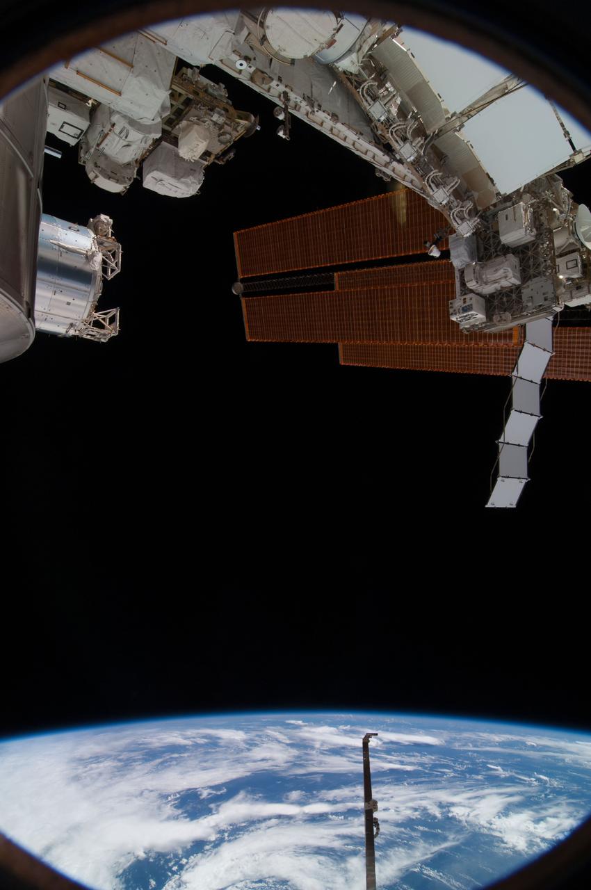
View of antenna and solar arrays (with an Earth limb in the background) taken from a window in the Russian Soyuz spacecraft currently docked to the International Space Station. Photo taken by an Expedition 36 crewmember. Per Twitter message: View out the window to the right of my seat in Soyuz while docked to ISS.
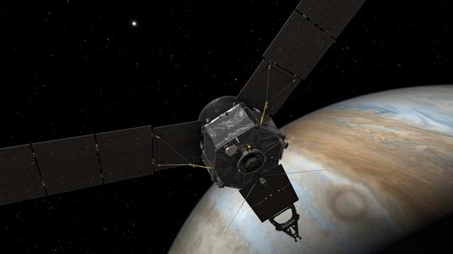
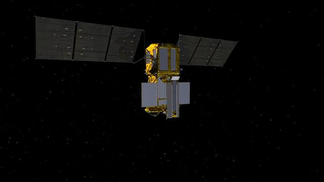
This illustration depicts NASA's Juno spacecraft at Jupiter, with its solar arrays and main antenna pointed toward the distant sun and Earth. http://photojournal.jpl.nasa.gov/catalog/PIA20703
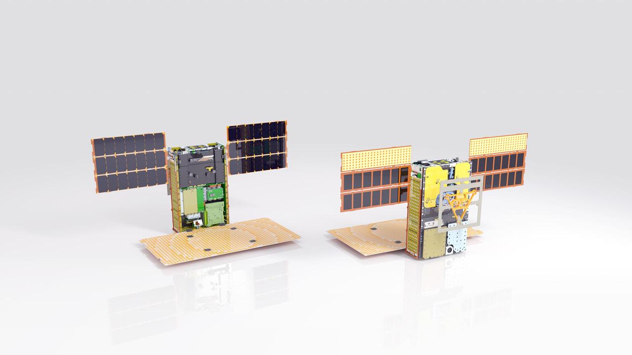
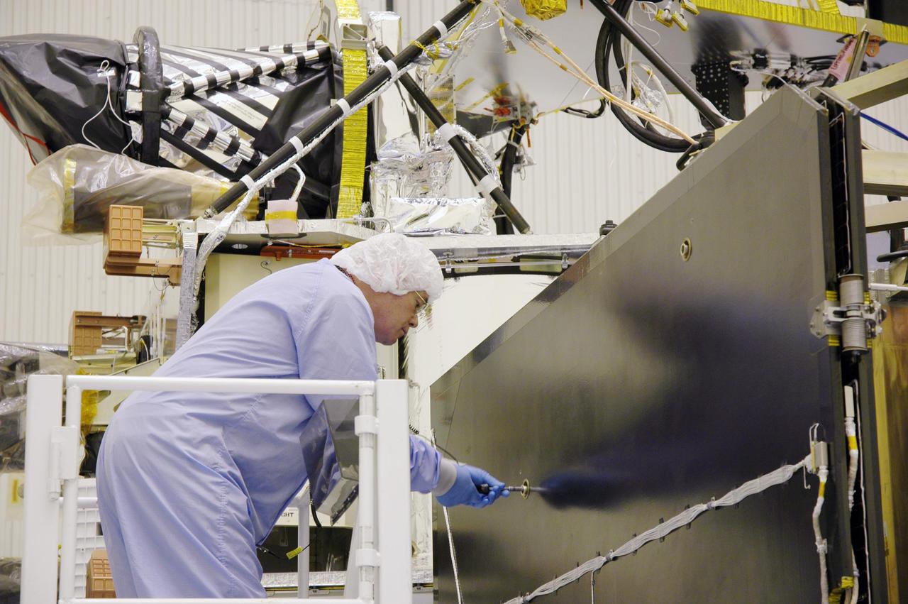
Illustration of one of the twin MarCO spacecraft with some key components labeled. Front cover is left out to show some internal components. Antennas and solar arrays are in deployed configuration. https://photojournal.jpl.nasa.gov/catalog/PIA22548
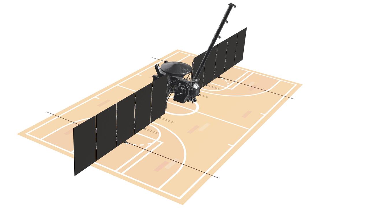
With its solar arrays and antennas fully extended, the Europa Clipper spacecraft stretches out larger than a basketball court: approximately 100 feet (30.5 meters) long and 58 feet (17.6 meters) wide. Depicted in this artist's concept against an illustration of a basketball court, Europa Clipper is the largest spacecraft NASA has ever built for a planetary mission. Europa Clipper is bound for the Jupiter system, where it will study the gas giant's icy moon Europa. Europa Clipper's three main science objectives are to determine the thickness of the moon's icy shell and its interactions with the ocean below, to investigate its composition, and to characterize its geology. The mission's detailed exploration of Europa will help scientists better understand the astrobiological potential for habitable worlds beyond our planet. https://photojournal.jpl.nasa.gov/catalog/PIA26433
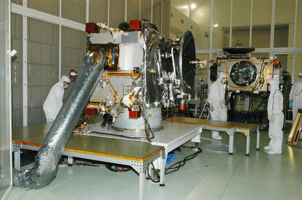
This image shows NASA Juno spacecraft undergoing environmental testing at Lockheed Martin Space Systems on Jan. 26, 2011. All 3 solar array wings are installed and stowed, and the large high-gain antenna is in place on the top of the avionics vault.
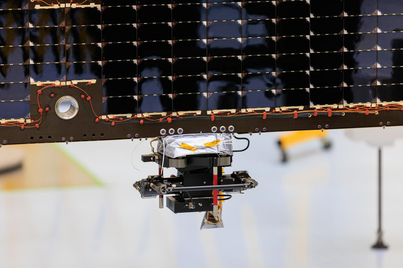
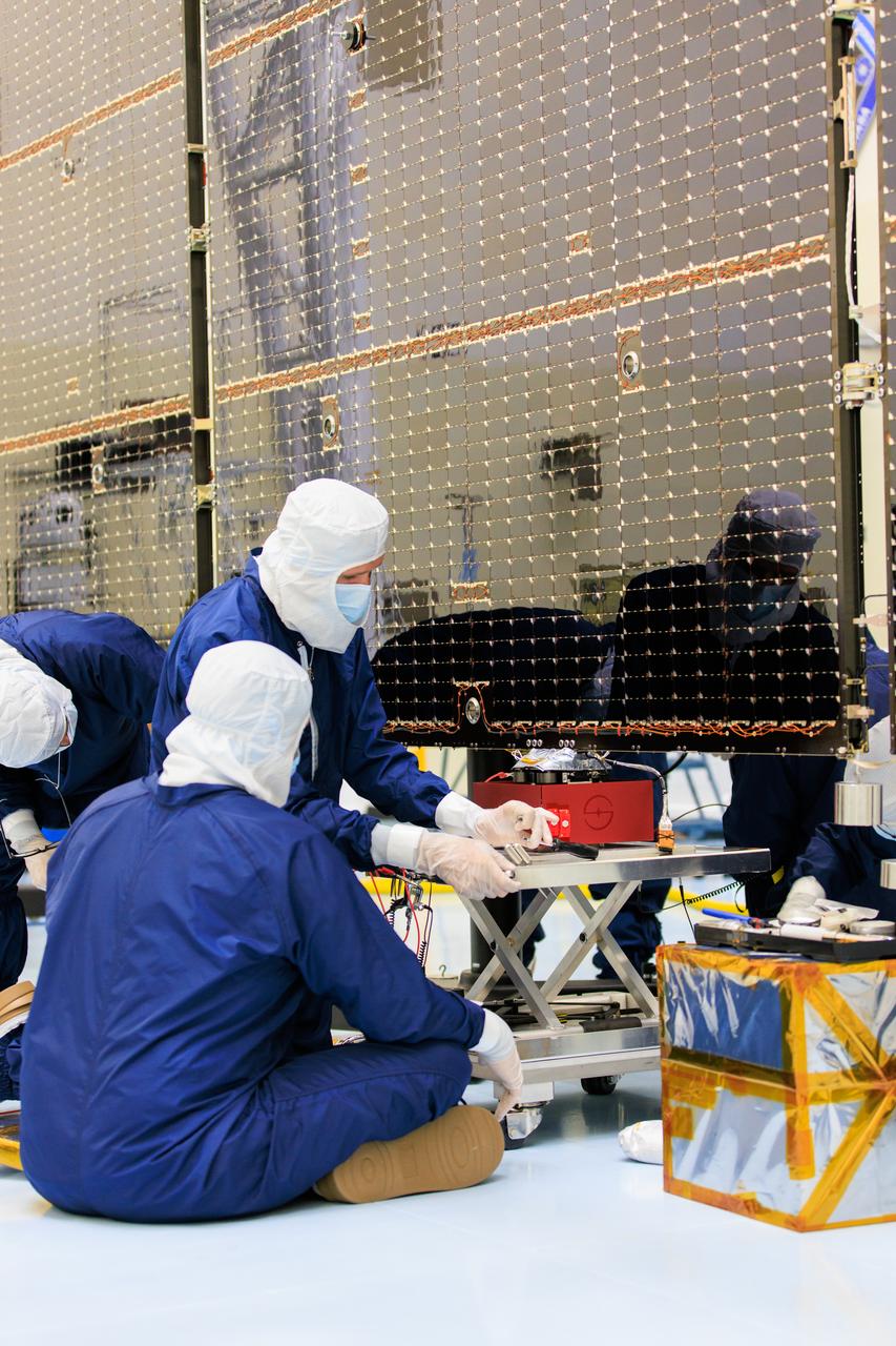
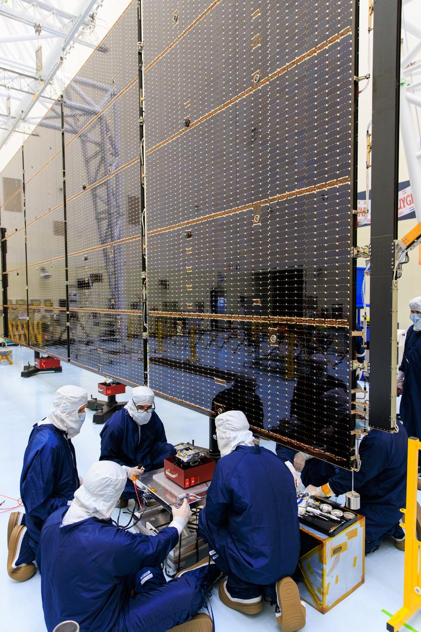
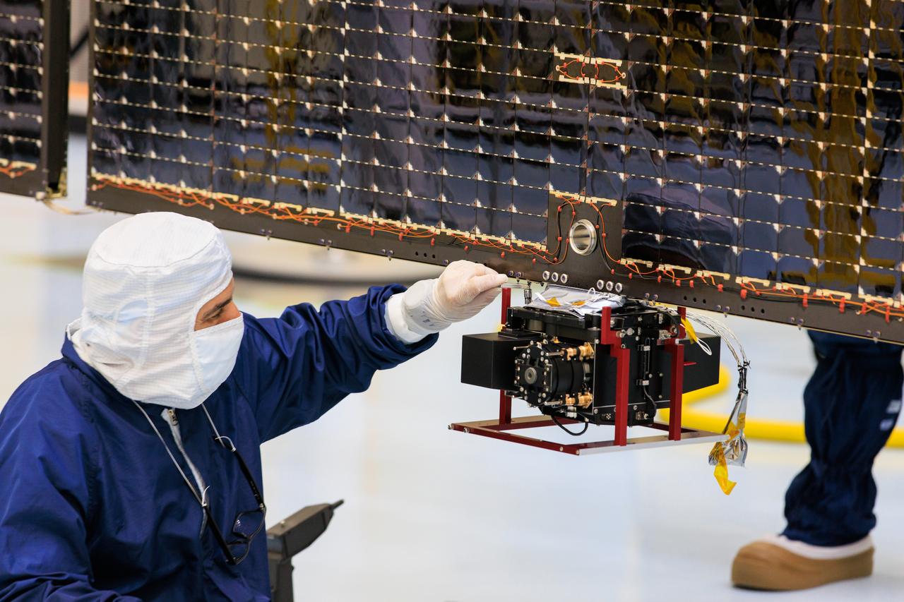
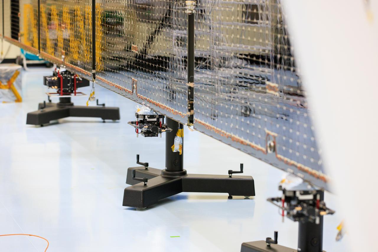
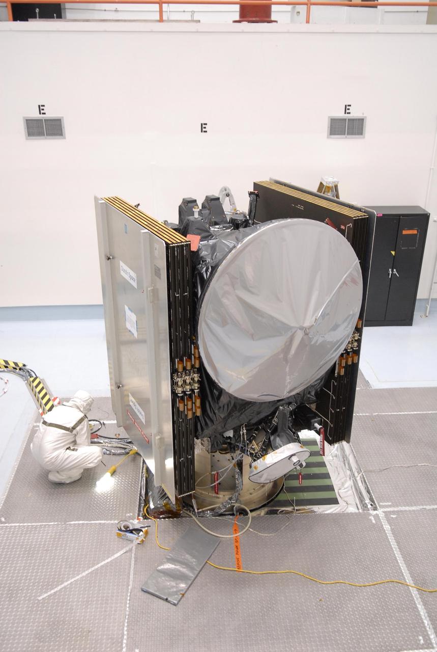
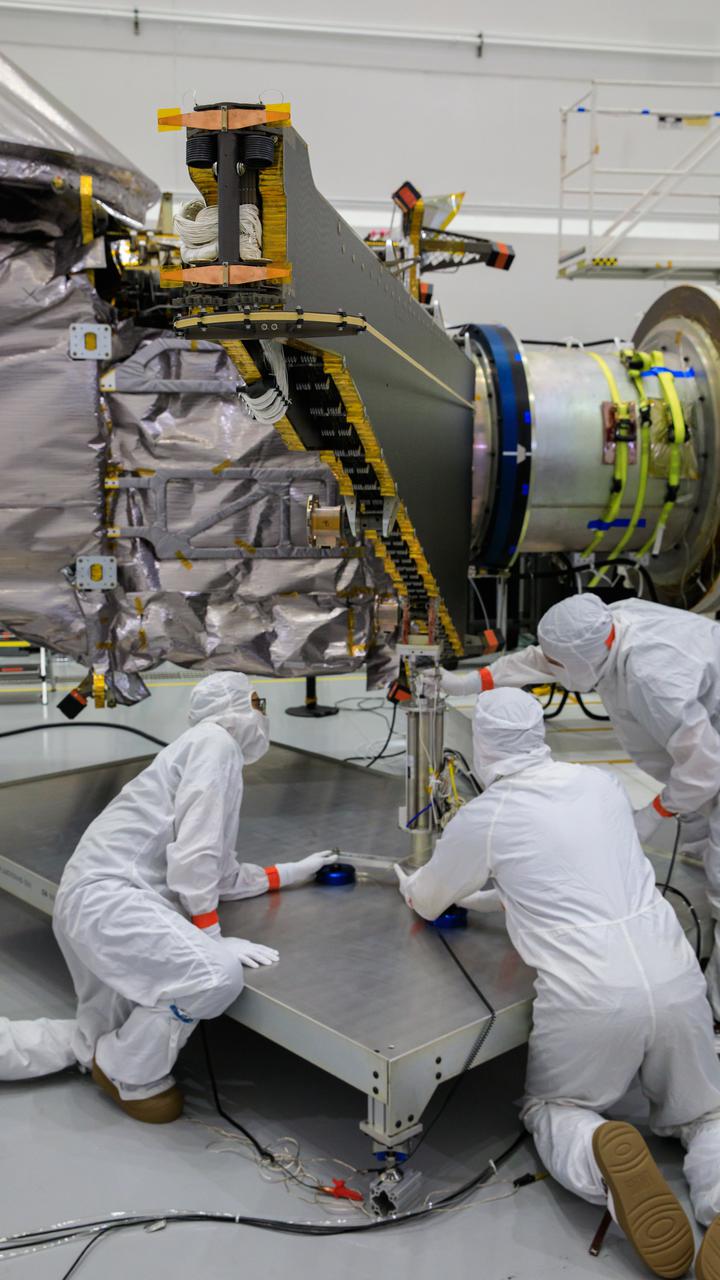
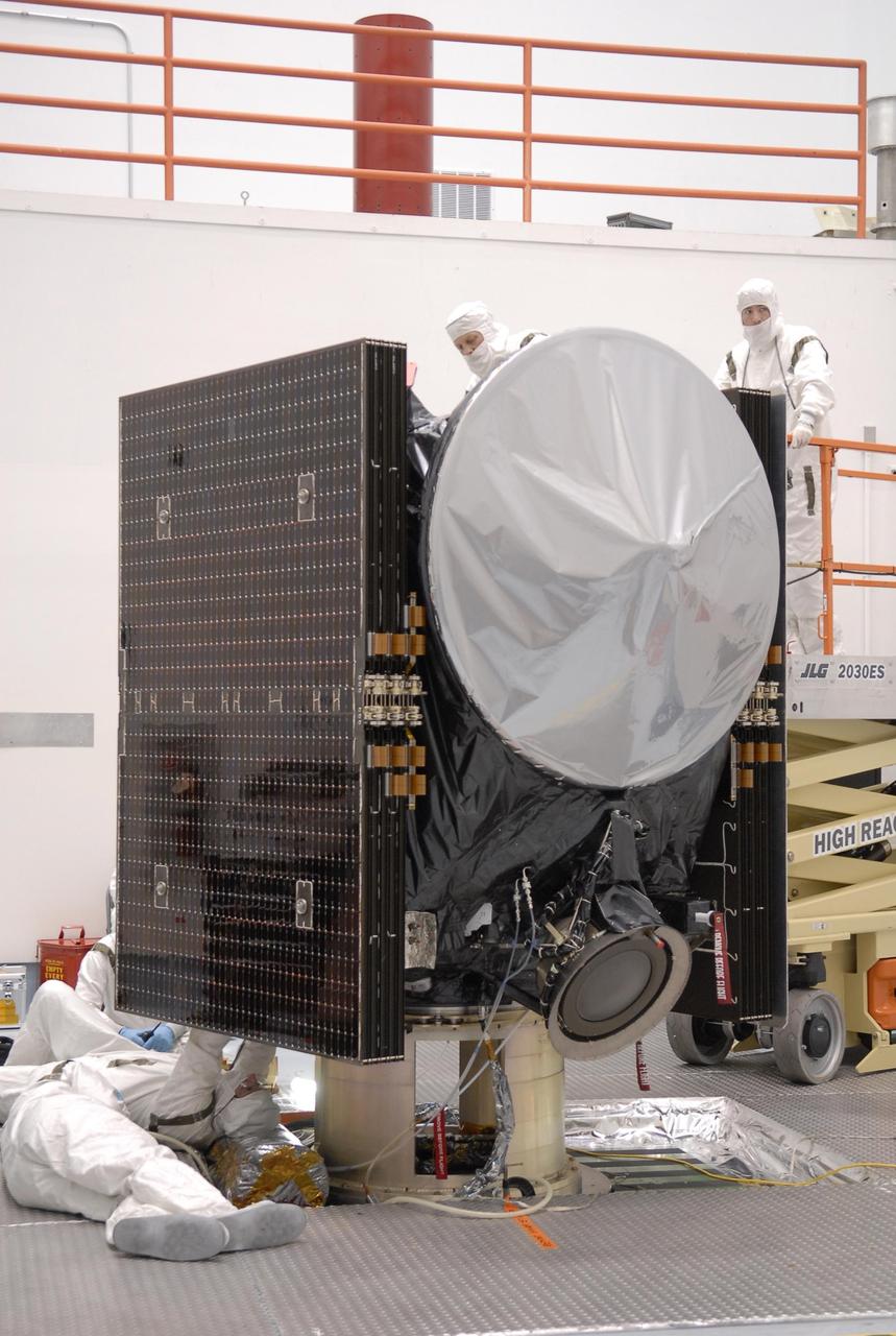
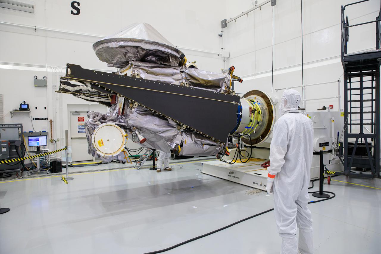
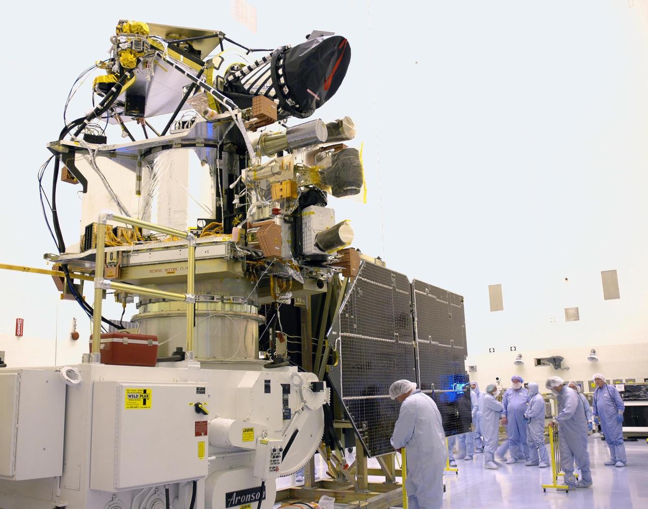
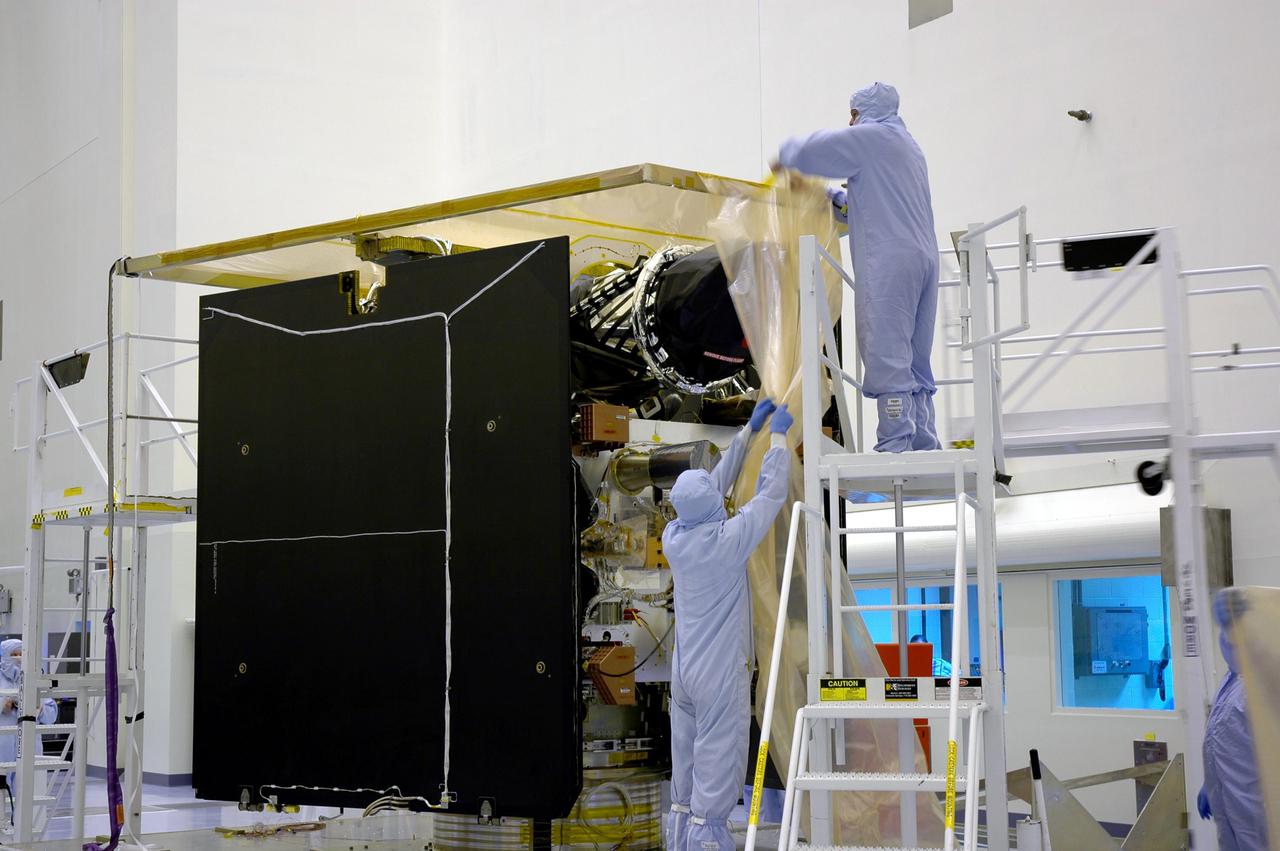
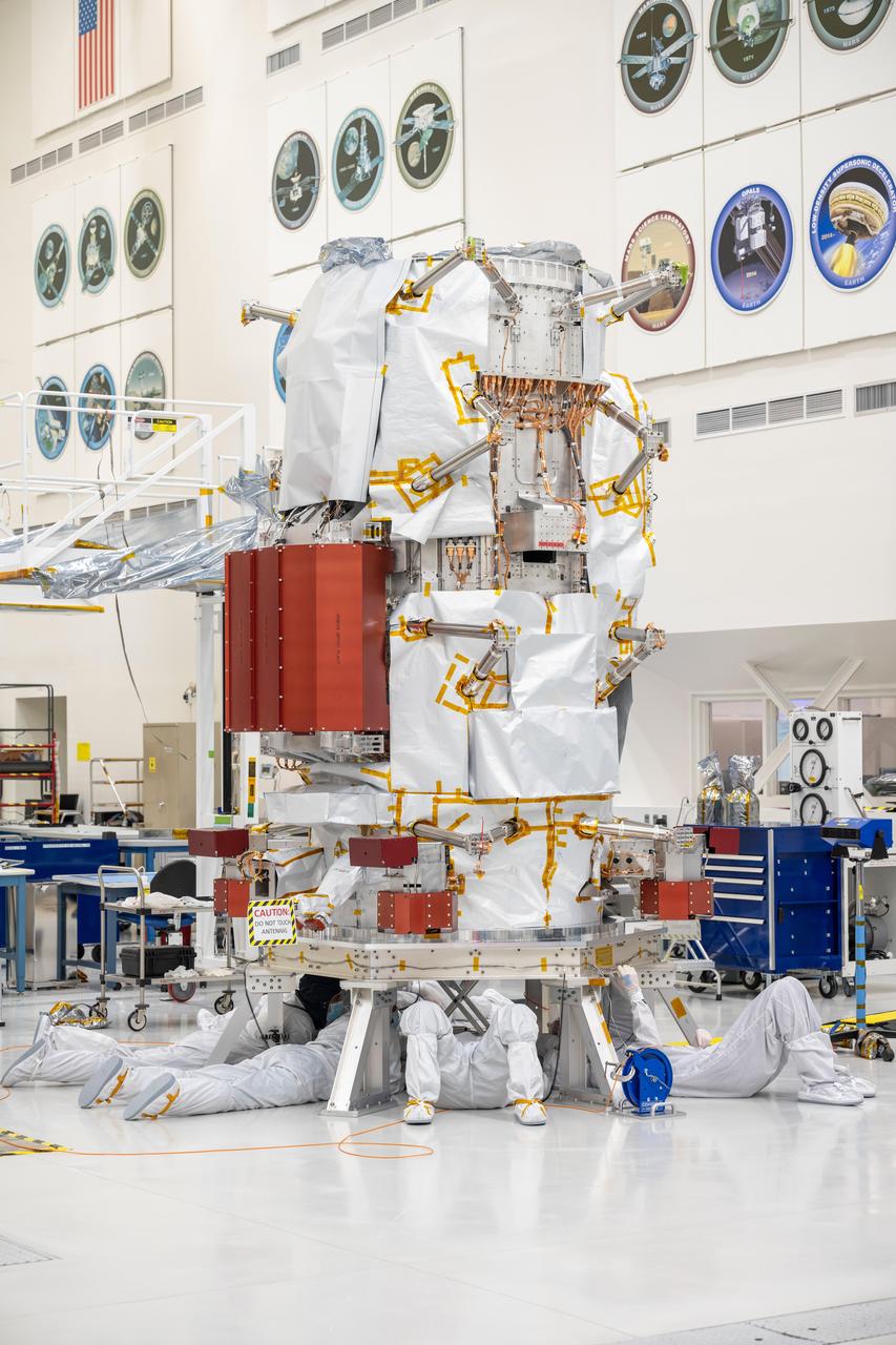
An antenna for the REASON, (Radar for Europa Assessment and Sounding: Ocean to Near-surface) instrument attaches to a solar array for NASA’s Europa Clipper spacecraft inside the Payload Hazardous Servicing Facility at the agency’s Kennedy Space Center in Florida on Wednesday, March 20, 2024. The Europa Clipper spacecraft will study Jupiter’s icy moon Europa, and the REASON instrument will use the antennas to send both both High Frequency (HF) and Very High Frequency (VHF) radio waves to penetrate up to 18 miles (30 kilometers) deep and search the ocean, measure ice thickness, and study the topography, composition, and roughness of Europa’s surface. The Europa Clipper spacecraft will ship to Florida later this year from NASA’s Jet Propulsion Lab in Southern California in preparation for launch aboard a SpaceX Falcon Heavy rocket from Kennedy’s Launch Complex 39A, targeting October.
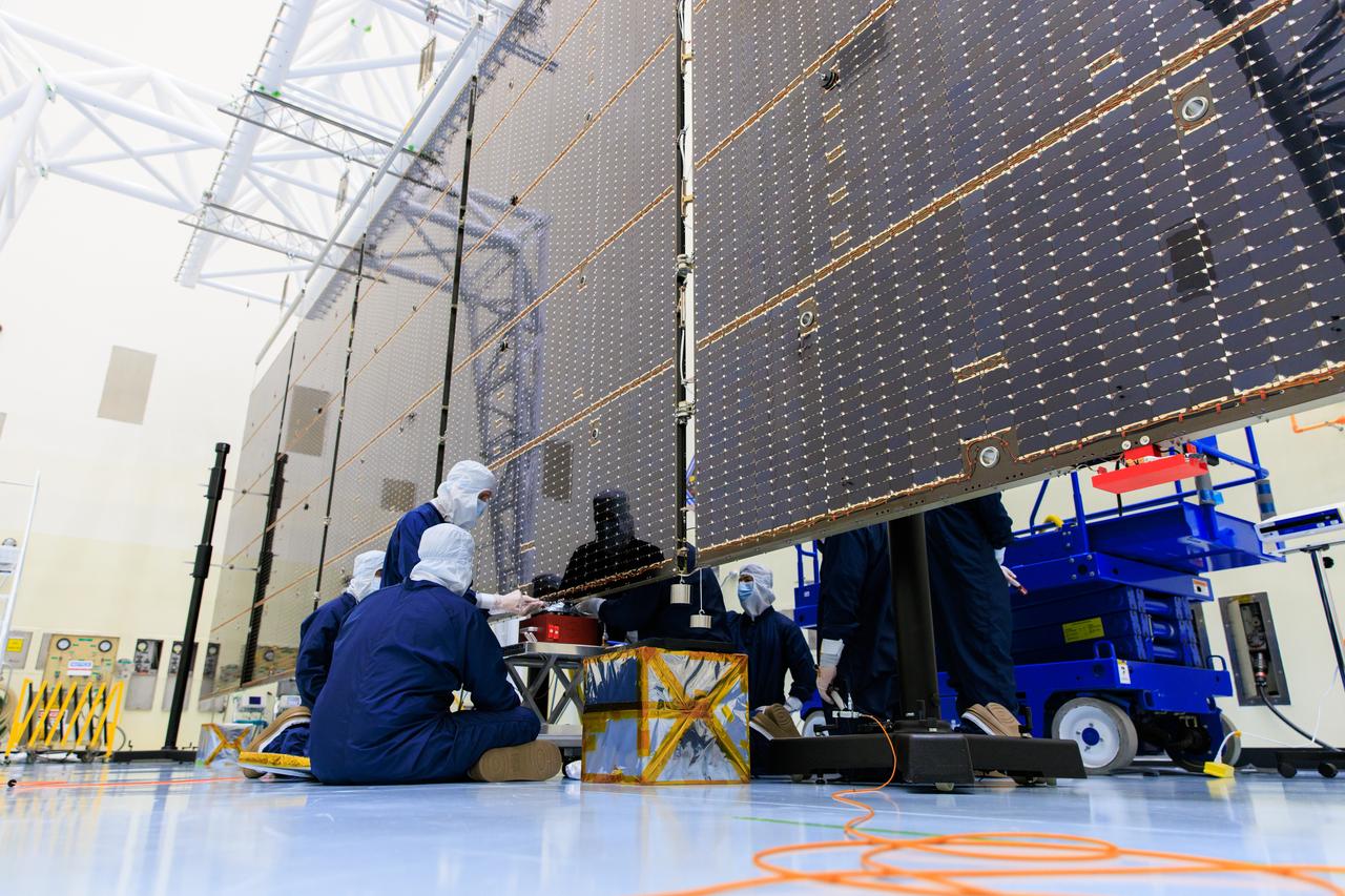
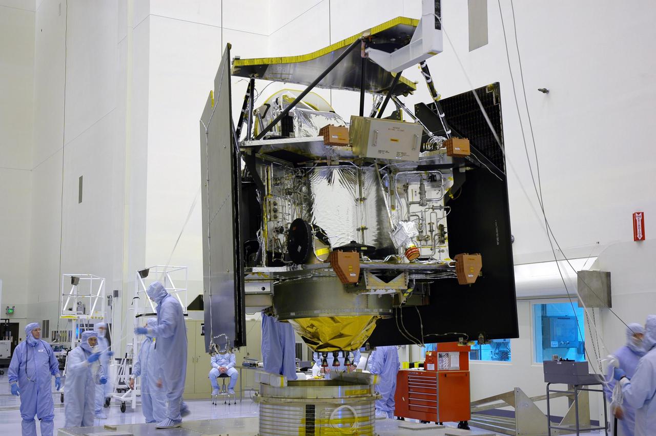
On March 20, technicians working inside the Payload Hazardous Servicing Facility at the agency’s Kennedy Space Center in Florida installed and began to test antennas on a solar array for NASA’s Europa Clipper spacecraft. The spacecraft will ship to Florida later this year from NASA’s Jet Propulsion Lab in Southern California in preparation for launch aboard a SpaceX Falcon Heavy rocket from Kennedy’s Launch Complex 39A. Europa Clipper is the largest spacecraft NASA has ever developed for a planetary mission, and it will seek to determine whether there are places below the surface of Jupiter’s icy moon, Europa, that could support life.
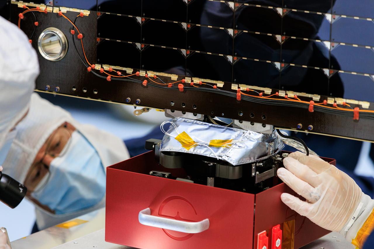
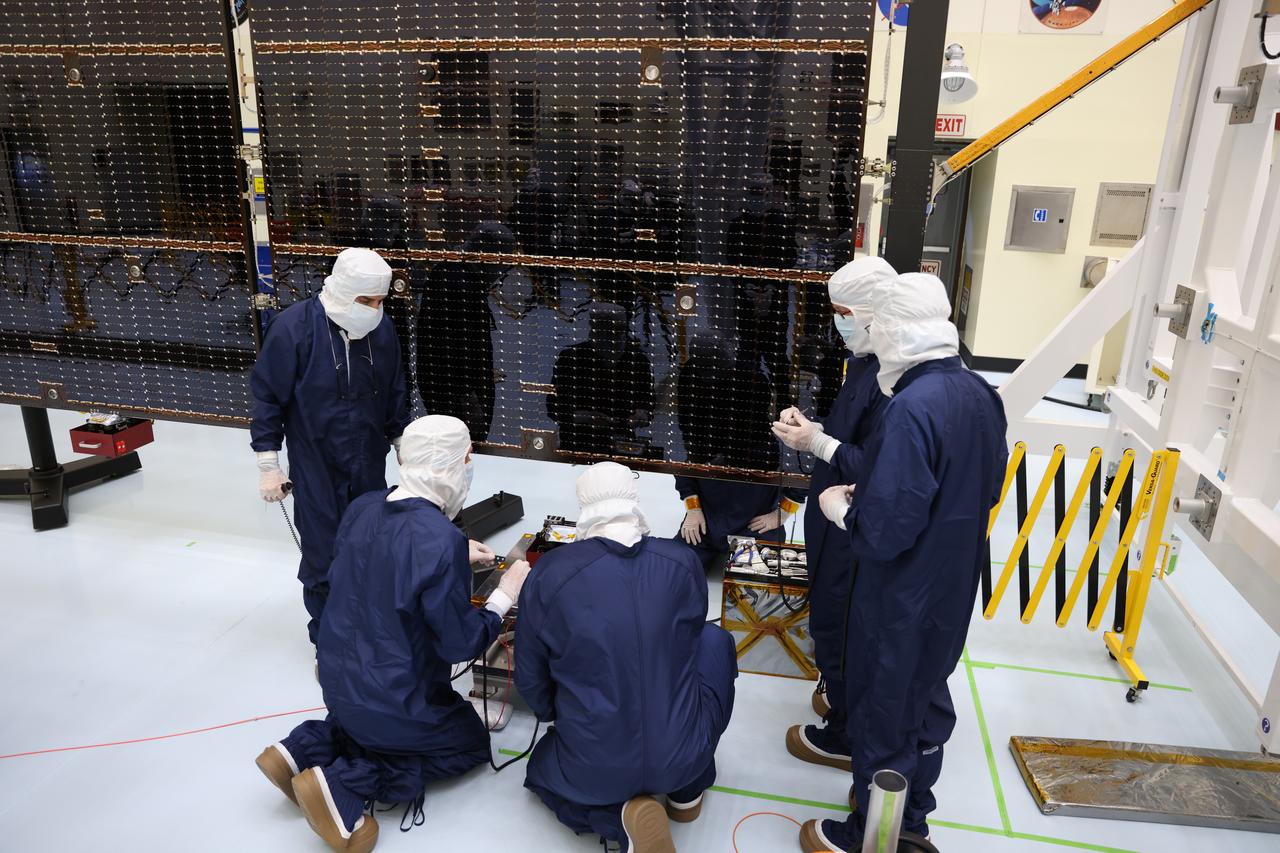
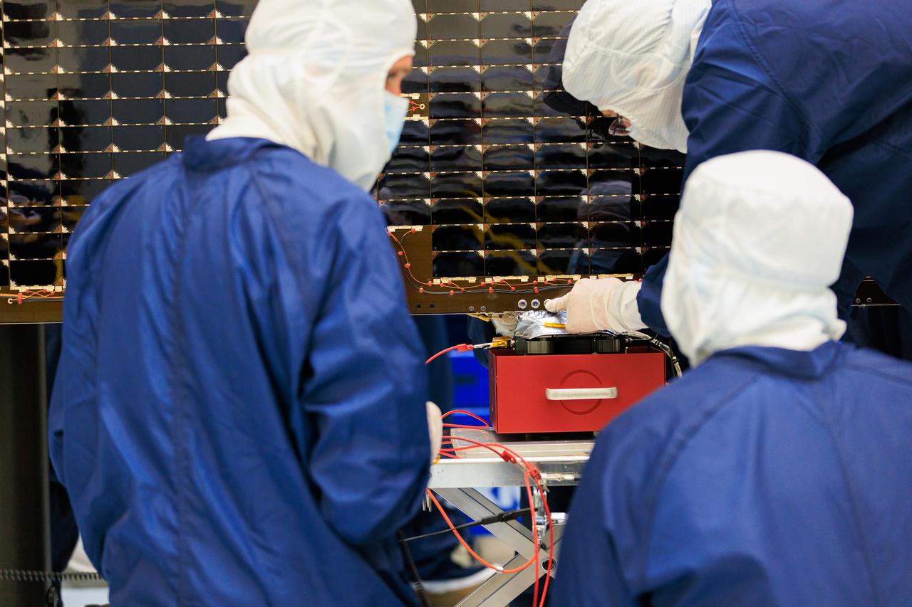
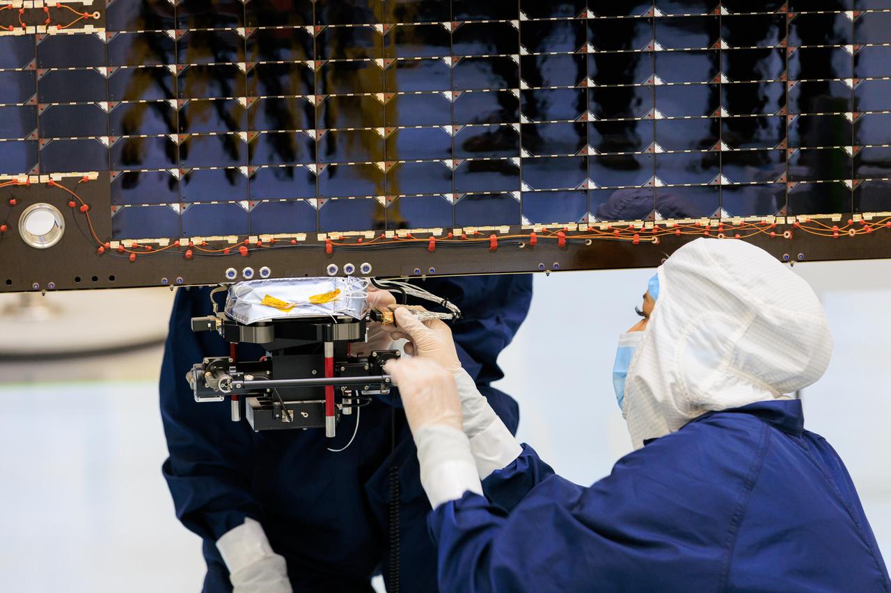
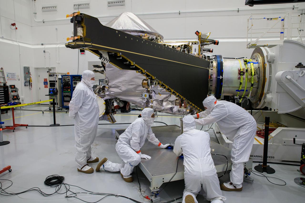
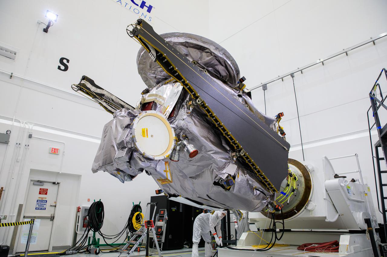
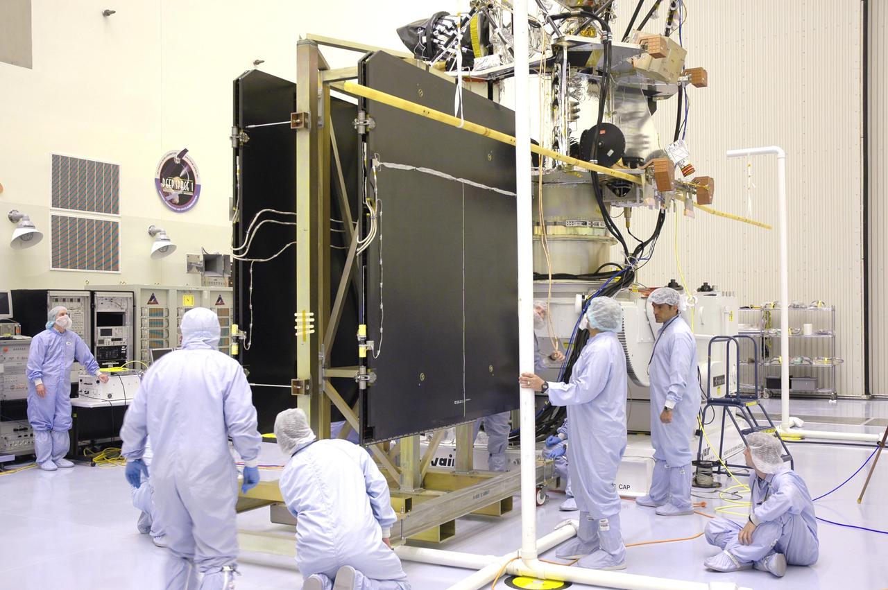
Technicians inside the Payload Hazardous Servicing Facility at NASA’s Kennedy Space Center in Florida install and test one of several antennas on a solar array Wednesday, March 20, 2024, for the agency’s Europa Clipper spacecraft which will study Jupiter’s icy moon, Europa, to determine if the planet can support life. REASON, (Radar for Europa Assessment and Sounding: Ocean to Near-surface) instrument will use the antennas to send both very high frequency radio waves and high frequency to penetrate up to 18 miles (30 kilometers) deep to search the ocean, measure ice thickness, and study the topography, composition, and roughness of Europa’s surface. The Europa Clipper spacecraft will ship to Florida later this year from NASA’s Jet Propulsion Lab in Southern California in preparation for launch aboard a SpaceX Falcon Heavy rocket from Kennedy’s Launch Complex 39A targeting October 2024.
Technicians inside the Payload Hazardous Servicing Facility at NASA’s Kennedy Space Center in Florida install and test one of several antennas on a solar array Wednesday, March 20, 2024, for the agency’s Europa Clipper spacecraft which will study Jupiter’s icy moon Europa to determine if the planet has conditions that could support life. REASON, (Radar for Europa Assessment and Sounding: Ocean to Near-surface) instrument will use the antennas to send both High Frequency (HF) and Very High Frequency (VHF) radio waves to penetrate up to 18 miles (30 kilometers) deep and search the ocean, measure ice thickness, and study the topography, composition, and roughness of Europa’s surface. The Europa Clipper spacecraft will ship to Florida later this year from NASA’s Jet Propulsion Lab in Southern California in preparation for launch aboard a SpaceX Falcon Heavy rocket from Kennedy’s Launch Complex 39A targeting October 2024.
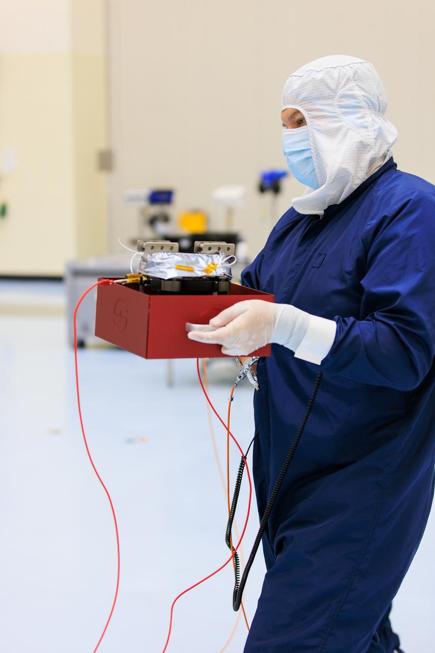
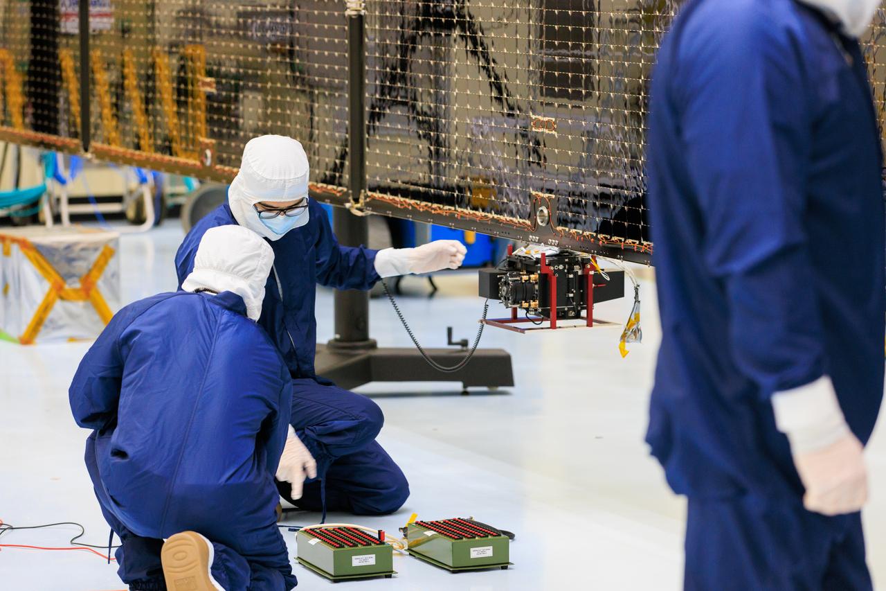
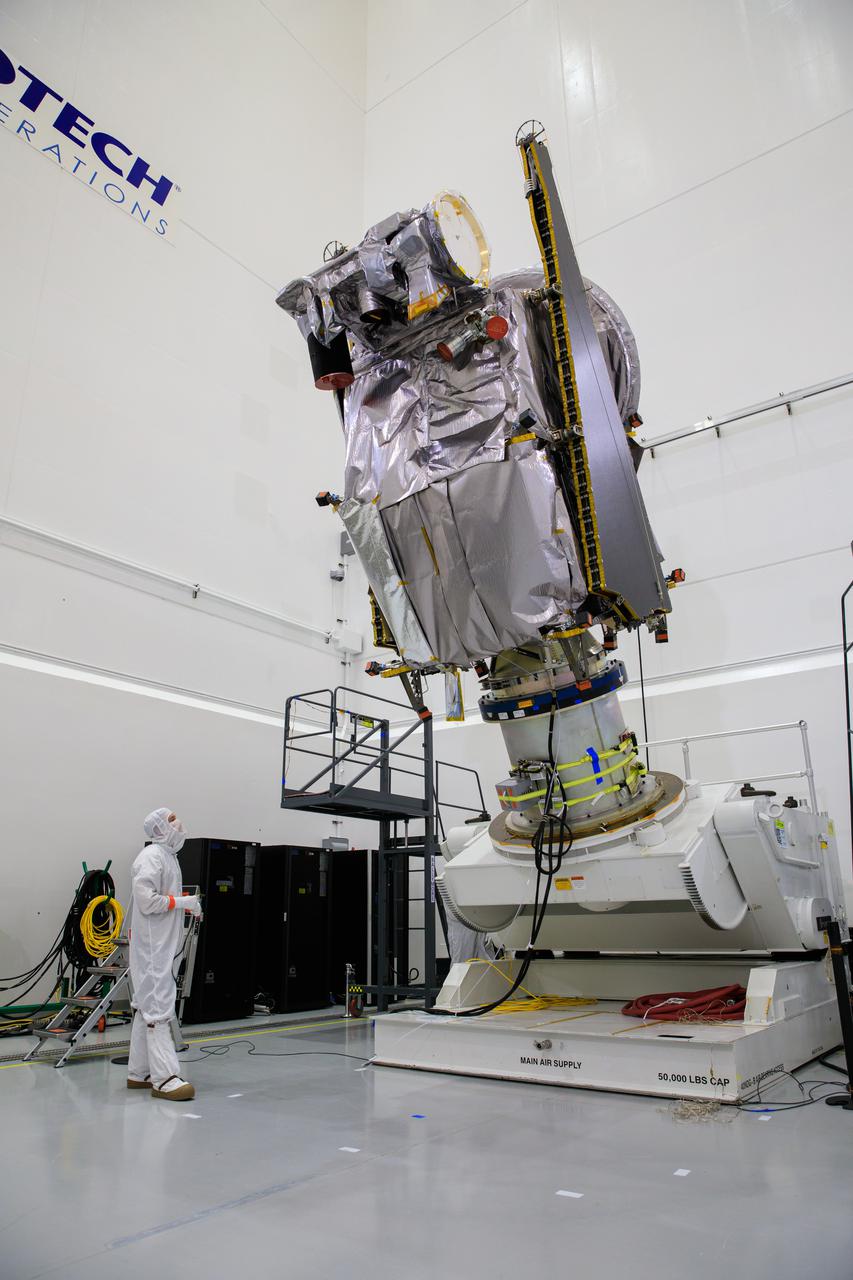
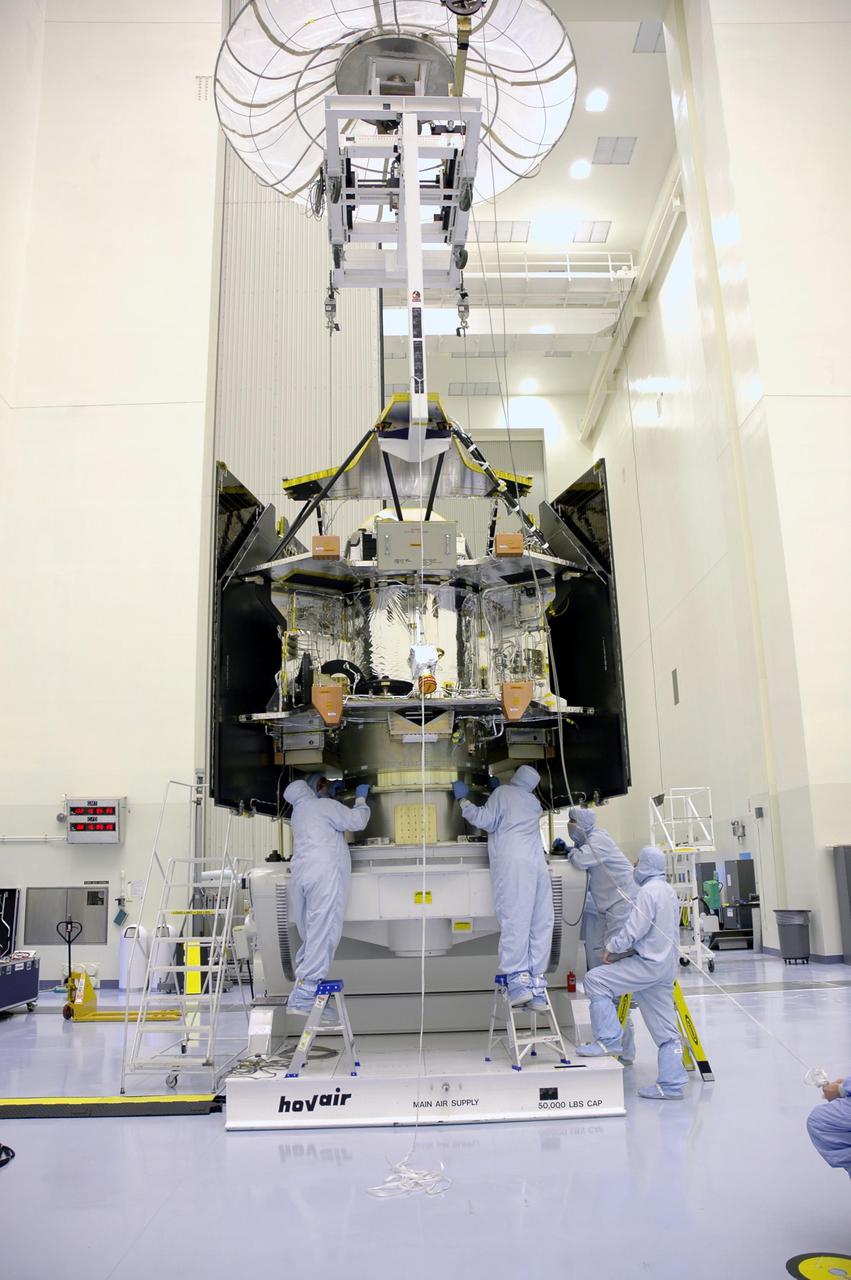
On Wednesday, March 20, 2024, a technician inside the Payload Hazardous Servicing Facility at NASA’s Kennedy Space Center in Florida carries an antenna that will attach to a solar array for the agency’s Europa Clipper spacecraft, which will study Jupiter’s icy moon Europa to determine if the planet has conditions that could support life. The REASON, (Radar for Europa Assessment and Sounding: Ocean to Near-surface) instrument will use the antennas to send both High Frequency (HF) and Very High Frequency (VHF) radio waves to penetrate up to 18 miles (30 kilometers) deep and search the ocean, measure ice thickness, and study the topography, composition, and roughness of Europa’s surface. The Europa Clipper spacecraft will ship to Florida later this year from NASA’s Jet Propulsion Lab in Southern California in preparation for launch aboard a SpaceX Falcon Heavy rocket from Kennedy’s Launch Complex 39A targeting October 2024.
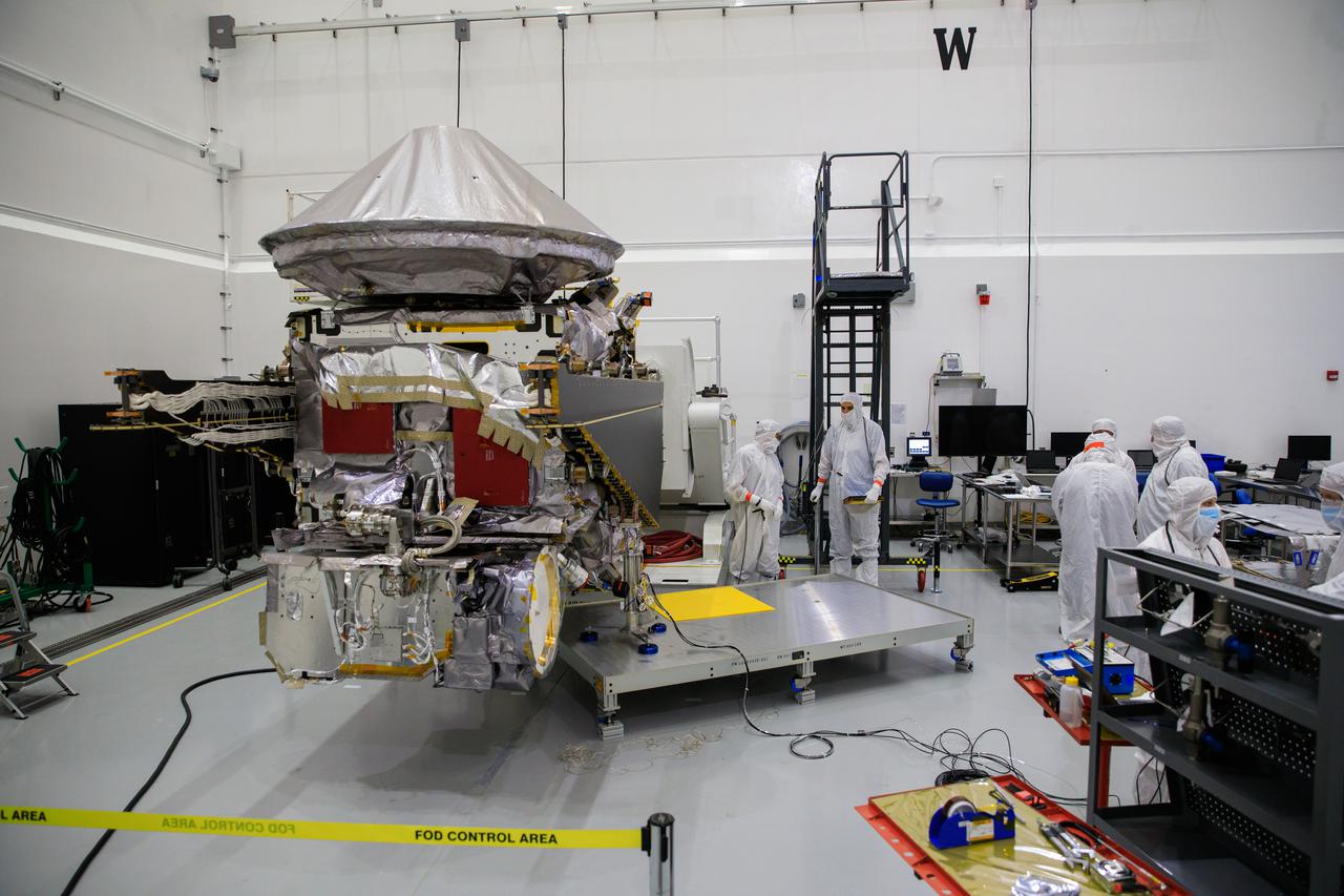
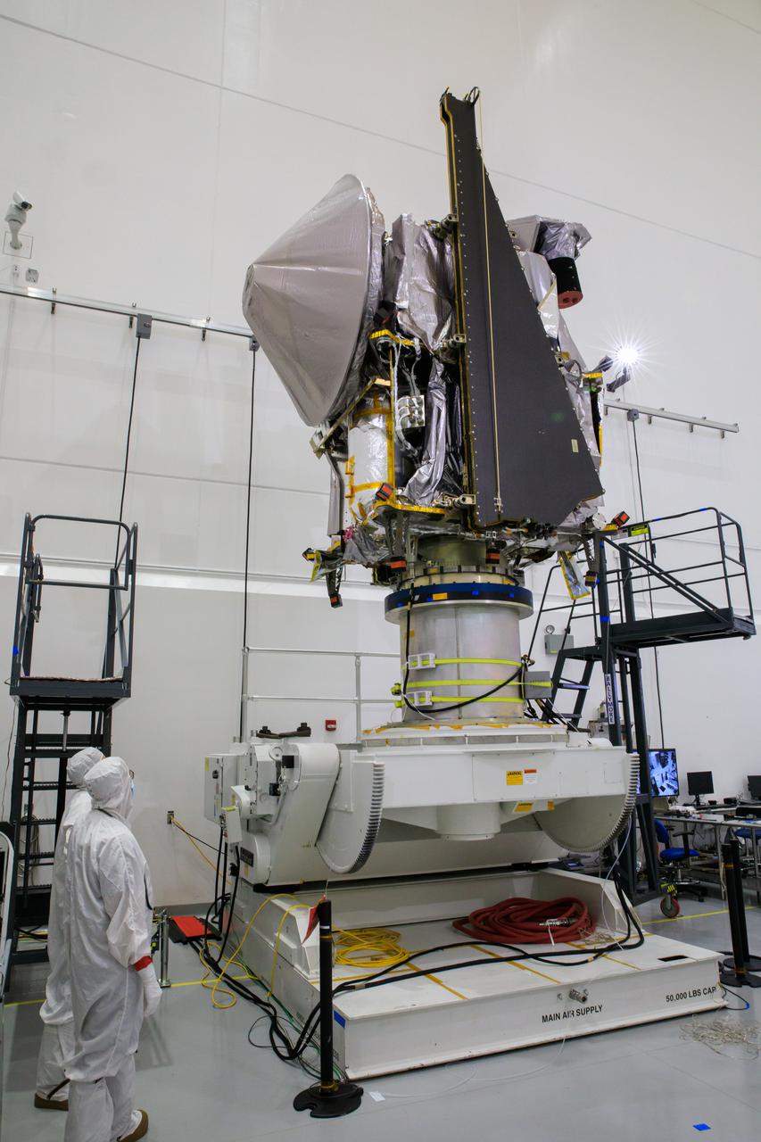
Technicians inside the Payload Hazardous Servicing Facility at NASA’s Kennedy Space Center in Florida install and test one of several antennas on a solar array Wednesday, March 20, 2024, for the agency’s Europa Clipper spacecraft which will study Jupiter’s icy moon Europa to determine if the planet has conditions that could support life. REASON, (Radar for Europa Assessment and Sounding: Ocean to Near-surface) instrument will use the antennas to send both High Frequency (HF) and Very High Frequency (VHF) radio waves to penetrate up to 18 miles (30 kilometers) deep and search the ocean, measure ice thickness, and study the topography, composition, and roughness of Europa’s surface. The Europa Clipper spacecraft will ship to Florida later this year from NASA’s Jet Propulsion Lab in Southern California in preparation for launch aboard a SpaceX Falcon Heavy rocket from Kennedy’s Launch Complex 39A targeting October 2024.
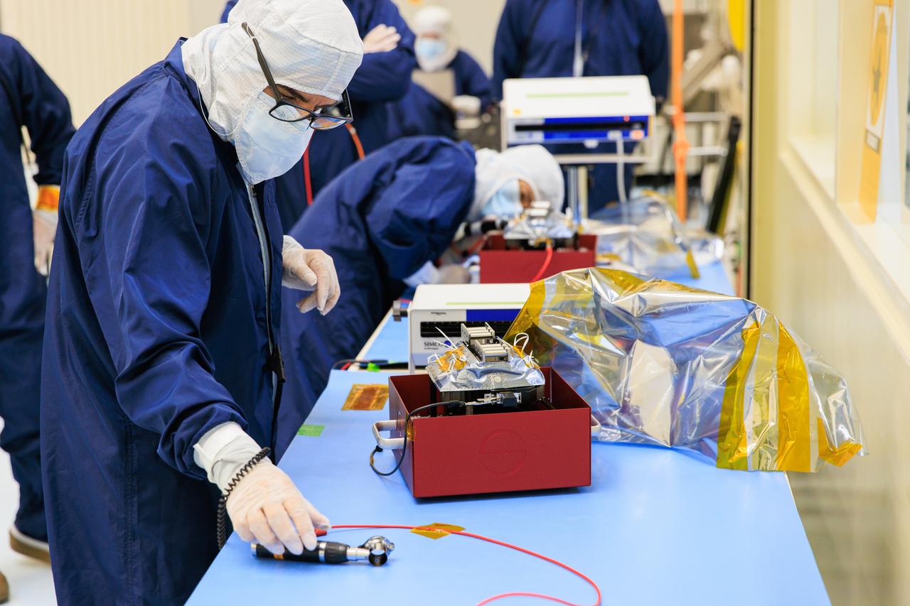
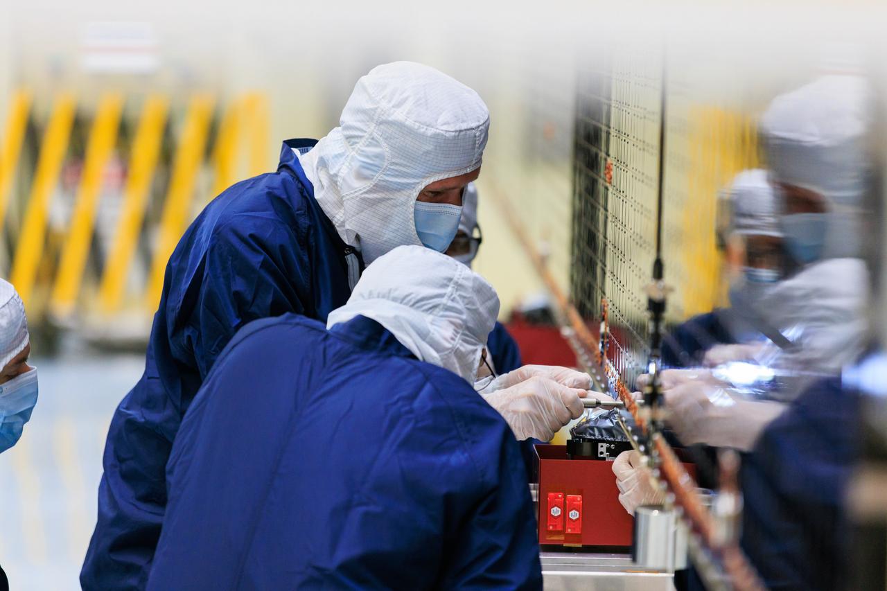
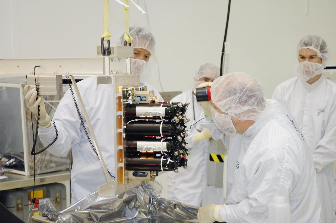
Technicians inside the Payload Hazardous Servicing Facility at NASA’s Kennedy Space Center in Florida test antennas on Wednesday, March 20, 2024, shortly before installing them on a solar array for the agency’s Europa Clipper spacecraft, which will study Jupiter’s icy moon Europa to determine if the planet has conditions that could support life. The REASON, (Radar for Europa Assessment and Sounding: Ocean to Near-surface) instrument will use the antennas to send both High Frequency (HF) and Very High Frequency (VHF) to penetrate up to 18 miles (30 kilometers) deep and search the ocean, measure ice thickness, and study the topography, composition, and roughness of Europa’s surface. The Europa Clipper spacecraft will ship to Florida later this year from NASA’s Jet Propulsion Lab in Southern California in preparation for launch aboard a SpaceX Falcon Heavy rocket from Kennedy’s Launch Complex 39A targeting October 2024.
Technicians inside the Payload Hazardous Servicing Facility at NASA’s Kennedy Space Center in Florida install and test one of several antennas on a solar array Wednesday, March 20, 2024, for the agency’s Europa Clipper spacecraft which will study Jupiter’s icy moon Europa to determine if the planet has conditions that could support life. REASON, (Radar for Europa Assessment and Sounding: Ocean to Near-surface) instrument will use the antennas to send both High Frequency (HF) and Very High Frequency (VHF) radio waves to penetrate up to 18 miles (30 kilometers) deep and search the ocean, measure ice thickness, and study the topography, composition, and roughness of Europa’s surface. The Europa Clipper spacecraft will ship to Florida later this year from NASA’s Jet Propulsion Lab in Southern California in preparation for launch aboard a SpaceX Falcon Heavy rocket from Kennedy’s Launch Complex 39A targeting October 2024.
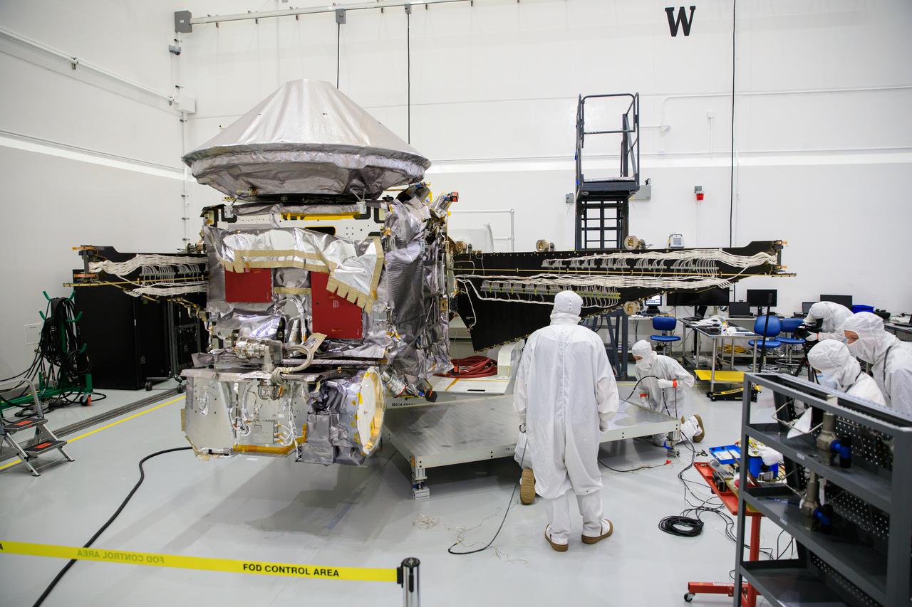
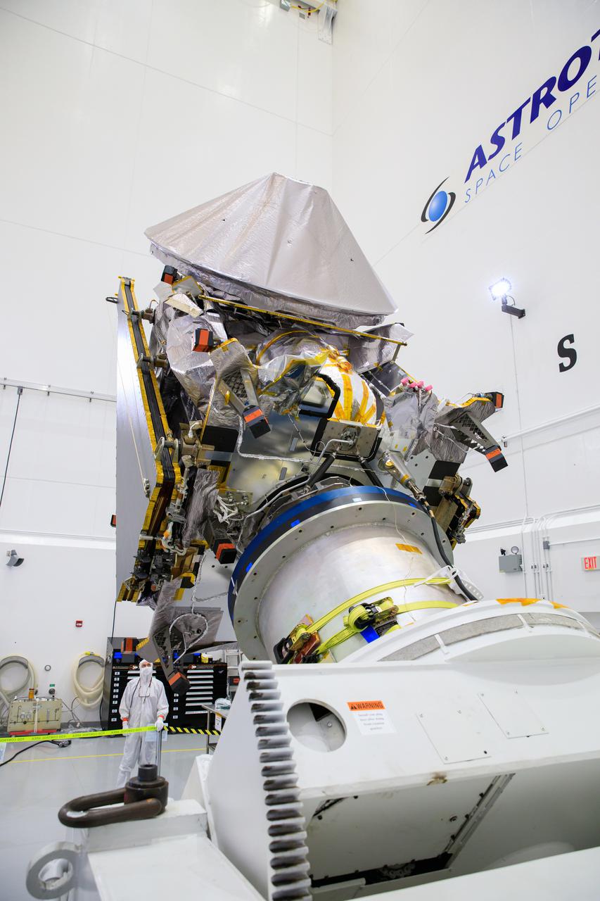
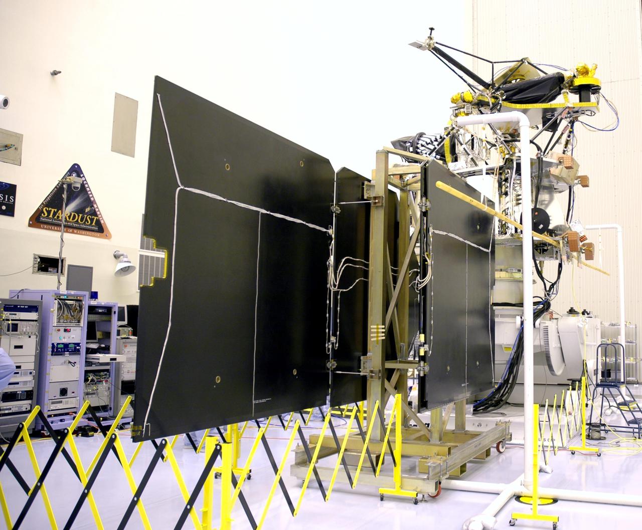
Technicians inside the Payload Hazardous Servicing Facility at NASA’s Kennedy Space Center in Florida install and test antennas on a solar array on Wednesday, March 20, 2024, for the agency’s Europa Clipper spacecraft which will study Jupiter’s icy moon Europa to determine if the planet has conditions that could support life. The REASON, (Radar for Europa Assessment and Sounding: Ocean to Near-surface) instrument will use the antennas to send both High Frequency (HF) and Very High Frequency (VHF) radio waves to penetrate up to 18 miles (30 kilometers) deep and search the ocean, measure ice thickness, and study the topography, composition, and roughness of Europa’s surface. The Europa Clipper spacecraft will ship to Florida later this year from NASA’s Jet Propulsion Lab in Southern California in preparation for launch aboard a SpaceX Falcon Heavy rocket from Kennedy’s Launch Complex 39A targeting October.
Technicians inside the Payload Hazardous Servicing Facility at NASA’s Kennedy Space Center in Florida install and test one of several antennas on a solar array Wednesday, March 20, 2024, for the agency’s Europa Clipper spacecraft which will study Jupiter’s icy moon Europa to determine if the planet has conditions that could support life. REASON, (Radar for Europa Assessment and Sounding: Ocean to Near-surface) instrument will use the antennas to send both High Frequency (HF) and Very High Frequency (VHF) radio waves to penetrate up to 18 miles (30 kilometers) deep and search the ocean, measure ice thickness, and study the topography, composition, and roughness of Europa’s surface. The Europa Clipper spacecraft will ship to Florida later this year from NASA’s Jet Propulsion Lab in Southern California in preparation for launch aboard a SpaceX Falcon Heavy rocket from Kennedy’s Launch Complex 39A targeting October 2024.
Technicians inside the Payload Hazardous Servicing Facility at NASA’s Kennedy Space Center in Florida install and test antennas on a solar array on Wednesday, March 20, 2024, for the agency’s Europa Clipper spacecraft which will study Jupiter’s icy moon Europa to determine if the planet has conditions that could support life. The REASON, (Radar for Europa Assessment and Sounding: Ocean to Near-surface) instrument will use the antennas to send both both High Frequency (HF) and Very High Frequency (VHF) radio waves to penetrate up to 18 miles (30 kilometers) deep and search the ocean, measure ice thickness, and study the topography, composition, and roughness of Europa’s surface. The Europa Clipper spacecraft will ship to Florida later this year from NASA’s Jet Propulsion Lab in Southern California in preparation for launch aboard a SpaceX Falcon Heavy rocket from Kennedy’s Launch Complex 39A targeting October.
Technicians inside the Payload Hazardous Servicing Facility at NASA’s Kennedy Space Center in Florida install and test antennas on a solar array on Wednesday, March 20, 2024, for the agency’s Europa Clipper spacecraft which will study Jupiter’s icy moon Europa to determine if the planet has conditions that could support life. The REASON, (Radar for Europa Assessment and Sounding: Ocean to Near-surface) instrument will use the antennas to send both High Frequency (HF) and Very High Frequency (VHF) radio waves to penetrate up to 18 miles (30 kilometers) deep and search the ocean, measure ice thickness, and study the topography, composition, and roughness of Europa’s surface. The Europa Clipper spacecraft will ship to Florida later this year from NASA’s Jet Propulsion Lab in Southern California in preparation for launch aboard a SpaceX Falcon Heavy rocket from Kennedy’s Launch Complex 39A targeting October.
Technicians inside the Payload Hazardous Servicing Facility at NASA’s Kennedy Space Center in Florida install and test one of several antennas on a solar array Wednesday, March 20, 2024, for the agency’s Europa Clipper spacecraft which will study Jupiter’s icy moon Europa to determine if the planet has conditions that could support life. REASON, (Radar for Europa Assessment and Sounding: Ocean to Near-surface) instrument will use the antennas to send both High Frequency (HF) and Very High Frequency (VHF) radio waves to penetrate up to 18 miles (30 kilometers) deep and search the ocean, measure ice thickness, and study the topography, composition, and roughness of Europa’s surface. The Europa Clipper spacecraft will ship to Florida later this year from NASA’s Jet Propulsion Lab in Southern California in preparation for launch aboard a SpaceX Falcon Heavy rocket from Kennedy’s Launch Complex 39A targeting October 2024.
Technicians inside the Payload Hazardous Servicing Facility at NASA’s Kennedy Space Center in Florida install and test antennas on a solar array on Wednesday, March 20, 2024, for the agency’s Europa Clipper spacecraft which will study Jupiter’s icy moon Europa to determine if the planet has conditions that could support life. The REASON, (Radar for Europa Assessment and Sounding: Ocean to Near-surface) instrument will use the antennas to send both High Frequency (HF) and Very High Frequency (VHF) radio waves to penetrate up to 18 miles (30 kilometers) deep and search the ocean, measure ice thickness, and study the topography, composition, and roughness of Europa’s surface. The Europa Clipper spacecraft will ship to Florida later this year from NASA’s Jet Propulsion Lab in Southern California in preparation for launch aboard a SpaceX Falcon Heavy rocket from Kennedy’s Launch Complex 39A targeting October.
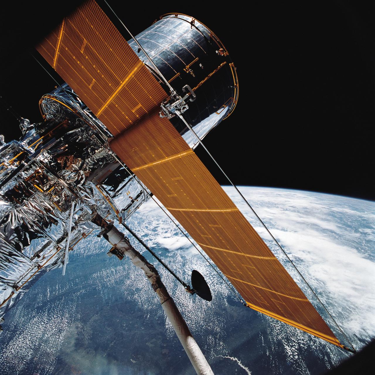
STS031-76-026 (25 April 1990) --- Most of the giant Hubble Space Telescope (HST) can be seen as it is suspended in space by Discovery's Remote Manipulator System (RMS) following the deployment of part of its solar panels and antennae. The photo was taken with a handheld Hasselblad camera. This was among the first photos NASA released on April 30, 1990, from the five-day STS 31 mission.
KENNEDY SPACE CENTER, FLA. -- At Astrotech, the Dawn spacecraft is on display for a media showing. On each side are the folded solar array panels. At the top is the high gain antenna, covered by a sun shade. At the bottom, also under cover, is one of the ion propulsion thrusters. Behind the antenna on the outside edge are the framing cameras. Dawn's goal is to characterize the conditions and processes of the solar system's earliest epoch by investigating in detail the largest protoplanets that have remained intact since their formations: asteroid Vesta and the dwarf planet Ceres. They reside in the extensive zone between Mars and Jupiter together with many other smaller bodies, called the asteroid belt. Photo credit: NASA/Kim Shiflett
Workers inside the Astrotech Space Operations Facility in Titusville, Florida, work to open and extend one of the solar arrays on NASA’s Lucy spacecraft on Aug. 19, 2021. Both solar arrays will be opened to make sure they operate correctly. In view installed on top of the spacecraft is the high gain antenna. Lucy is scheduled to launch no earlier than Saturday, Oct. 16, on a United Launch Alliance Atlas V 401 rocket from Space Launch Complex 41 at Cape Canaveral Space Force Station. NASA’s Launch Services Program based at Kennedy Space Center is managing the launch. Over its 12-year primary mission, Lucy will explore a record-breaking number of asteroids, flying by one asteroid in the solar system’s main belt and seven Trojan asteroids. Additionally, Lucy’s path will circle back to Earth three times for gravity assists, making it the first spacecraft ever to return to the vicinity of Earth from the outer solar system.
Workers inside the Astrotech Space Operations Facility in Titusville, Florida, begin to extend one of the solar arrays on NASA’s Lucy spacecraft on Aug. 19, 2021. Both solar arrays will be opened to make sure they operate correctly. In view installed on top of the spacecraft is the high gain antenna. Lucy is scheduled to launch no earlier than Saturday, Oct. 16, on a United Launch Alliance Atlas V 401 rocket from Space Launch Complex 41 at Cape Canaveral Space Force Station. NASA’s Launch Services Program based at Kennedy Space Center is managing the launch. Over its 12-year primary mission, Lucy will explore a record-breaking number of asteroids, flying by one asteroid in the solar system’s main belt and seven Trojan asteroids. Additionally, Lucy’s path will circle back to Earth three times for gravity assists, making it the first spacecraft ever to return to the vicinity of Earth from the outer solar system.
Workers inside the Astrotech Space Operations Facility in Titusville, Florida, work to open and extend one of the solar arrays on NASA’s Lucy spacecraft on Aug. 19, 2021. Both solar arrays will be opened to make sure they operate correctly. In view installed on top of the spacecraft is the high gain antenna. Lucy is scheduled to launch no earlier than Saturday, Oct. 16, on a United Launch Alliance Atlas V 401 rocket from Space Launch Complex 41 at Cape Canaveral Space Force Station. NASA’s Launch Services Program based at Kennedy Space Center is managing the launch. Over its 12-year primary mission, Lucy will explore a record-breaking number of asteroids, flying by one asteroid in the solar system’s main belt and seven Trojan asteroids. Additionally, Lucy’s path will circle back to Earth three times for gravity assists, making it the first spacecraft ever to return to the vicinity of Earth from the outer solar system.
Workers inside the Astrotech Space Operations Facility in Titusville, Florida, work to open and extend one of the solar arrays on NASA’s Lucy spacecraft on Aug. 19, 2021. Both solar arrays will be opened to make sure they operate correctly. In view installed on top of the spacecraft is the high gain antenna. Lucy is scheduled to launch no earlier than Saturday, Oct. 16, on a United Launch Alliance Atlas V 401 rocket from Space Launch Complex 41 at Cape Canaveral Space Force Station. NASA’s Launch Services Program based at Kennedy Space Center is managing the launch. Over its 12-year primary mission, Lucy will explore a record-breaking number of asteroids, flying by one asteroid in the solar system’s main belt and seven Trojan asteroids. Additionally, Lucy’s path will circle back to Earth three times for gravity assists, making it the first spacecraft ever to return to the vicinity of Earth from the outer solar system.
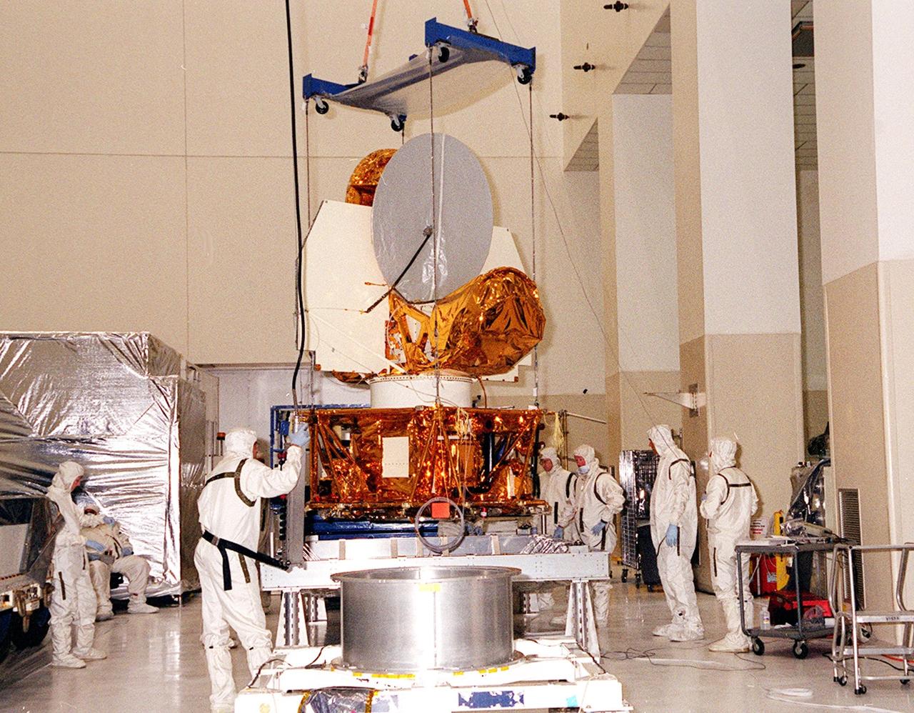
In the Space Assembly and Encapsulation Facility 2, the Mars Odyssey Orbiter is suspended from an overhead crane that is moving it toward the third stage of a Delta rocket for installation. In front on the spacecraft can be seen a high gain antenna; at right is the folded solar array assembly. The Mars Odyssey is scheduled for launch at 11:02 a.m. EDT April 7, 2001, aboard a Delta II rocket from Launch Pad 17-A, Cape Canaveral Air Force Station. The spacecraft is designed to map the surface of Mars

In the Space Assembly and Encapsulation Facility 2, the Mars Odyssey Orbiter is suspended from an overhead crane that is moving it toward the third stage of a Delta rocket for installation. In front on the spacecraft can be seen a high gain antenna; at right is the folded solar array assembly. The Mars Odyssey is scheduled for launch at 11:02 a.m. EDT April 7, 2001, aboard a Delta II rocket from Launch Pad 17-A, Cape Canaveral Air Force Station. The spacecraft is designed to map the surface of Mars
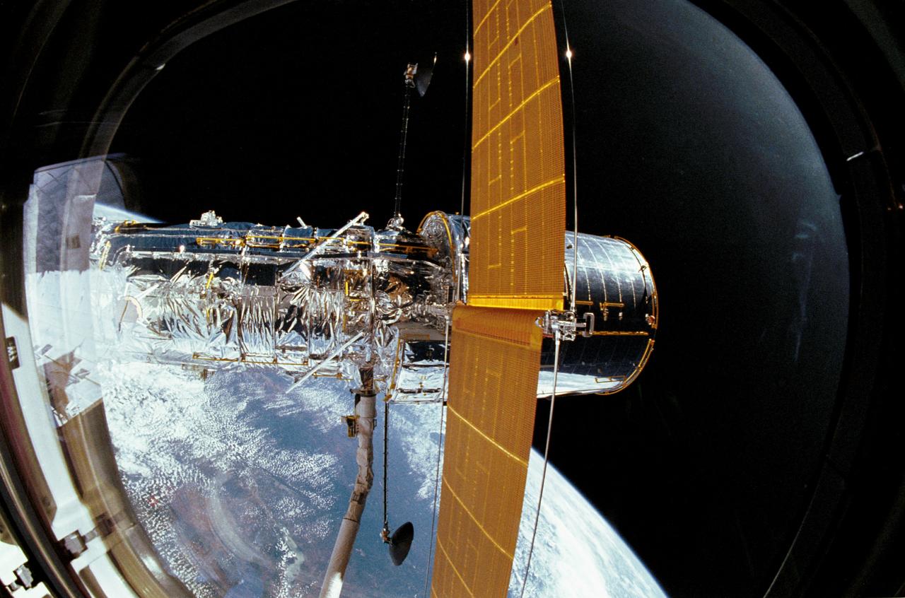
STS031-03-014 (25 April 1990) --- The Hubble Space Telescope (HST), still in the grasp of Discovery's Remote Manipulator System (RMS), is backdropped over Earth some 332 nautical miles below. In this scene, HST has deployed one of its solar array panels but is yet to have extended the second. This scene was captured with a 35mm camera aimed through an overhead window on aft the flight deck.
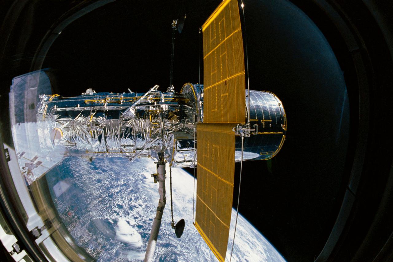
STS031-03-009 (25 April 1990) --- The Hubble Space Telescope (HST), still in the grasp of Discovery's remote manipulator system (RMS), is backdropped over Earth some 332 nautical miles below. In this scene, HST has deployed one of its solar array panels but is yet to have extended the second. This scene was captured with a 35mm camera aimed through an overhead window on the aft flight deck.
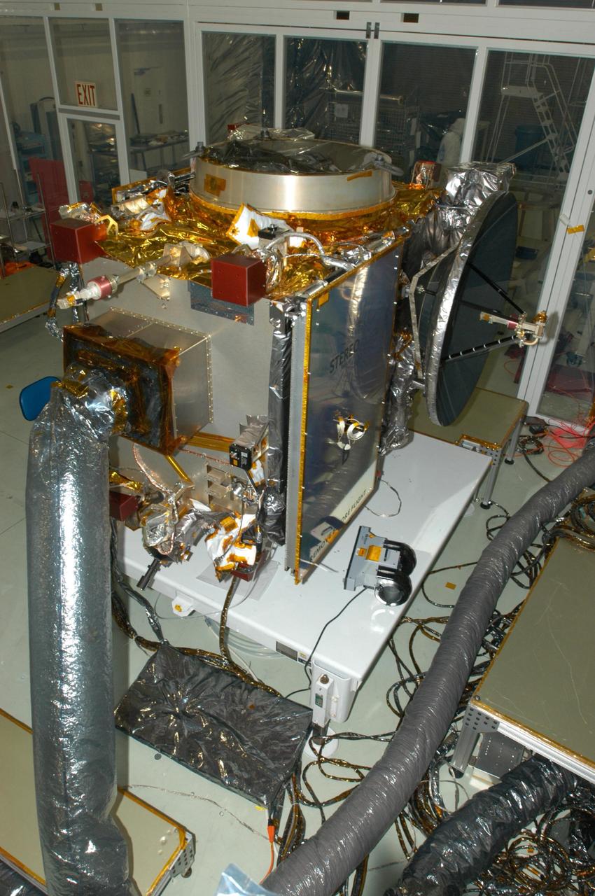
KENNEDY SPACE CENTER, FLA. - At Astrotech Space Operations in Titusville, Fla., the STEREO observatory "A" is ready for solar array deployment and high-gain antenna tests. STEREO, which stands for Solar Terrestrial Relations Observatory, consists of two spacecraft whose mission is to take measurements of the sun and solar wind in 3-D, for the first time. This new view will improve our understanding of space weather and its impact on the Earth. Preparations are under way for a liftoff aboard a Delta rocket no earlier than July 30. Photo credit: NASA/George Shelton

KENNEDY SPACE CENTER, FLA. - At Astrotech Space Operations in Titusville, Fla., engineers have completed installing the solar array on STEREO spacecraft "A." The panel displaying the "A" is a protective cover on the solar array to protect it during ground processing. The dish in front is a high gain antenna. Under black protective wrap at right is the Heliospheric Imager instrument, part of the Sun Earth Connection Coronal and Heliospheric Investigation (SECCHI) package of four instruments that will study the 3-D evolution of coronal mass ejections, from birth at the Sun's surface through the corona and interplanetary medium to its eventual impact at Earth. The long silver cylinder in the front, at right of the antenna, is the In situ Measurements of Particles and CME Transients, known as IMPACT, boom. The red protective covers are removed before flight. STEREO consists of two spacecraft whose mission is the first to take measurements of the sun and solar wind in 3-D. This new view will improve our understanding of space weather and its impact on the Earth. Preparations are under way for a liftoff aboard a Delta rocket no earlier than July 22. Photo credit: NASA/George Shelton

iss073e0000415 (April 21, 2025) --- NASA astronauts Anne McClain (bottom) and Nichole Ayers (top), both Expedition 73 Flight Engineers, checkout spacesuit hardware in the Quest airlock and review procedures for a May 1 spacewalk. The spacewalkers will install a modification kit on the International Space Station’s port side truss structure preparing it for a new rollout solar array and relocate an antenna that communicates with commercial spacecraft.
Workers in the Space Assembly and Encapsulation Facility 2 check the placement of the Mars Odyssey Orbiter as it is lowered onto the third stage of a Delta rocket below for installation. Visible above is the cone-shaped high gain antenna and the black solar array assembly. The Mars Odyssey is scheduled for launch at 11:02 a.m. EDT April 7, 2001, aboard a Delta II rocket from Launch Pad 17-A, Cape Canaveral Air Force Station. The spacecraft is designed to map the surface of Mars

Workers in the Space Assembly and Encapsulation Facility 2 check the placement of the Mars Odyssey Orbiter as it is lowered onto the third stage of a Delta rocket below for installation. Visible above is the cone-shaped high gain antenna and the black solar array assembly. The Mars Odyssey is scheduled for launch at 11:02 a.m. EDT April 7, 2001, aboard a Delta II rocket from Launch Pad 17-A, Cape Canaveral Air Force Station. The spacecraft is designed to map the surface of Mars
Workers in the Space Assembly and Encapsulation Facility 2 check the connections of the Mars Odyssey Orbiter on the third stage of a Delta rocket. Visible above is the cone-shaped high gain antenna and the black solar array assembly. The Mars Odyssey is scheduled for launch at 11:02 a.m. EDT April 7, 2001, aboard a Delta II rocket from Launch Pad 17-A, Cape Canaveral Air Force Station. The spacecraft is designed to map the surface of Mars

Workers in the Space Assembly and Encapsulation Facility 2 check the connections of the Mars Odyssey Orbiter on the third stage of a Delta rocket. Visible above is the cone-shaped high gain antenna and the black solar array assembly. The Mars Odyssey is scheduled for launch at 11:02 a.m. EDT April 7, 2001, aboard a Delta II rocket from Launch Pad 17-A, Cape Canaveral Air Force Station. The spacecraft is designed to map the surface of Mars
KENNEDY SPACE CENTER, FLA. -- At Astrotech, the Dawn spacecraft is on display for a media showing. On each side are the folded solar array panels. At the top is the high gain antenna, covered by a sun shade. At the bottom, also under cover, is one of the ion propulsion thrusters. Behind the antenna on the outside edge are the framing cameras, which are the scientific imaging system of the Dawn Mission. Dawn's goal is to characterize the conditions and processes of the solar system's earliest epoch by investigating in detail the largest protoplanets that have remained intact since their formations: asteroid Vesta and the dwarf planet Ceres. They reside in the extensive zone between Mars and Jupiter together with many other smaller bodies, called the asteroid belt. Photo credit: NASA/Kim Shiflett

KENNEDY SPACE CENTER, FLA. -- At Astrotech, photographers dressed in clean-room suits are able to shoot the Dawn spacecraft in its entirety before it is prepared for launch. Seen on each side are the folded solar array panels. At the top is the high gain antenna, covered by a sun shade. Dawn's goal is to characterize the conditions and processes of the solar system's earliest epoch by investigating in detail the largest protoplanets that have remained intact since their formations: asteroid Vesta and the dwarf planet Ceres. They reside in the extensive zone between Mars and Jupiter together with many other smaller bodies, called the asteroid belt. Photo credit: NASA/Kim Shiflett

KENNEDY SPACE CENTER, FLA. -- At Astrotech, photographers dressed in clean-room suits are able to shoot the Dawn spacecraft in its entirety before it is prepared for launch. Seen on each side are the folded solar array panels. At the top is the high gain antenna, covered by a sun shade. Dawn's goal is to characterize the conditions and processes of the solar system's earliest epoch by investigating in detail the largest protoplanets that have remained intact since their formations: asteroid Vesta and the dwarf planet Ceres. They reside in the extensive zone between Mars and Jupiter together with many other smaller bodies, called the asteroid belt. Photo credit: NASA/Kim Shiflett
KENNEDY SPACE CENTER, FLA. -- At Astrotech, technicians prepare the Dawn spacecraft for a media showing. On each side are the folded solar array panels. At the top is the high gain antenna, covered by a sun shade. At the bottom is one of the ion propulsion thrusters. Dawn's goal is to characterize the conditions and processes of the solar system's earliest epoch by investigating in detail the largest protoplanets that have remained intact since their formations: asteroid Vesta and the dwarf planet Ceres. They reside in the extensive zone between Mars and Jupiter together with many other smaller bodies, called the asteroid belt. Photo credit: NASA/Kim Shiflett
NASA’s Lucy spacecraft is moved to the horizontal position on a rotation stand inside the Astrotech Space Operations Facility in Titusville, Florida, on Sept. 1, 2021. In view, the high gain antenna and solar arrays have been installed on the Lucy spacecraft. Lucy is scheduled to launch no earlier than Saturday, Oct. 16, on a United Launch Alliance Atlas V 401 rocket from Launch Pad 41 at Cape Canaveral Space Force Station. NASA’s Launch Services Program based at Kennedy Space Center is managing the launch. Over its 12-year primary mission, Lucy will explore a record-breaking number of asteroids, flying by one asteroid in the solar system’s main belt and seven Trojan asteroids. Additionally, Lucy’s path will circle back to Earth three times for gravity assists, making it the first spacecraft ever to return to the vicinity of Earth from the outer solar system.
NASA’s Lucy spacecraft is moved to the vertical position on a rotation stand inside the Astrotech Space Operations Facility in Titusville, Florida, on Sept. 1, 2021. In view, the high gain antenna and solar arrays have been installed on the Lucy spacecraft. Lucy is scheduled to launch no earlier than Saturday, Oct. 16, on a United Launch Alliance Atlas V 401 rocket from Launch Pad 41 at Cape Canaveral Space Force Station. NASA’s Launch Services Program based at Kennedy Space Center is managing the launch. Over its 12-year primary mission, Lucy will explore a record-breaking number of asteroids, flying by one asteroid in the solar system’s main belt and seven Trojan asteroids. Additionally, Lucy’s path will circle back to Earth three times for gravity assists, making it the first spacecraft ever to return to the vicinity of Earth from the outer solar system.
NASA’s Lucy spacecraft is moved to the horizontal position on a rotation stand inside the Astrotech Space Operations Facility in Titusville, Florida, on Sept. 1, 2021. In view, the high gain antenna and solar arrays have been installed on the Lucy spacecraft. Lucy is scheduled to launch no earlier than Saturday, Oct. 16, on a United Launch Alliance Atlas V 401 rocket from Launch Pad 41 at Cape Canaveral Space Force Station. NASA’s Launch Services Program based at Kennedy Space Center is managing the launch. Over its 12-year primary mission, Lucy will explore a record-breaking number of asteroids, flying by one asteroid in the solar system’s main belt and seven Trojan asteroids. Additionally, Lucy’s path will circle back to Earth three times for gravity assists, making it the first spacecraft ever to return to the vicinity of Earth from the outer solar system.
NASA’s Lucy spacecraft is moved to the horizontal position on a rotation stand inside the Astrotech Space Operations Facility in Titusville, Florida, on Sept. 1, 2021. In view, the high gain antenna and solar arrays have been installed on the Lucy spacecraft. Lucy is scheduled to launch no earlier than Saturday, Oct. 16, on a United Launch Alliance Atlas V 401 rocket from Launch Pad 41 at Cape Canaveral Space Force Station. NASA’s Launch Services Program based at Kennedy Space Center is managing the launch. Over its 12-year primary mission, Lucy will explore a record-breaking number of asteroids, flying by one asteroid in the solar system’s main belt and seven Trojan asteroids. Additionally, Lucy’s path will circle back to Earth three times for gravity assists, making it the first spacecraft ever to return to the vicinity of Earth from the outer solar system.
NASA’s Lucy spacecraft is moved to the vertical position on a rotation stand inside the Astrotech Space Operations Facility in Titusville, Florida, on Sept. 1, 2021. In view, the high gain antenna and solar arrays have been installed on the Lucy spacecraft. Lucy is scheduled to launch no earlier than Saturday, Oct. 16, on a United Launch Alliance Atlas V 401 rocket from Launch Pad 41 at Cape Canaveral Space Force Station. NASA’s Launch Services Program based at Kennedy Space Center is managing the launch. Over its 12-year primary mission, Lucy will explore a record-breaking number of asteroids, flying by one asteroid in the solar system’s main belt and seven Trojan asteroids. Additionally, Lucy’s path will circle back to Earth three times for gravity assists, making it the first spacecraft ever to return to the vicinity of Earth from the outer solar system.
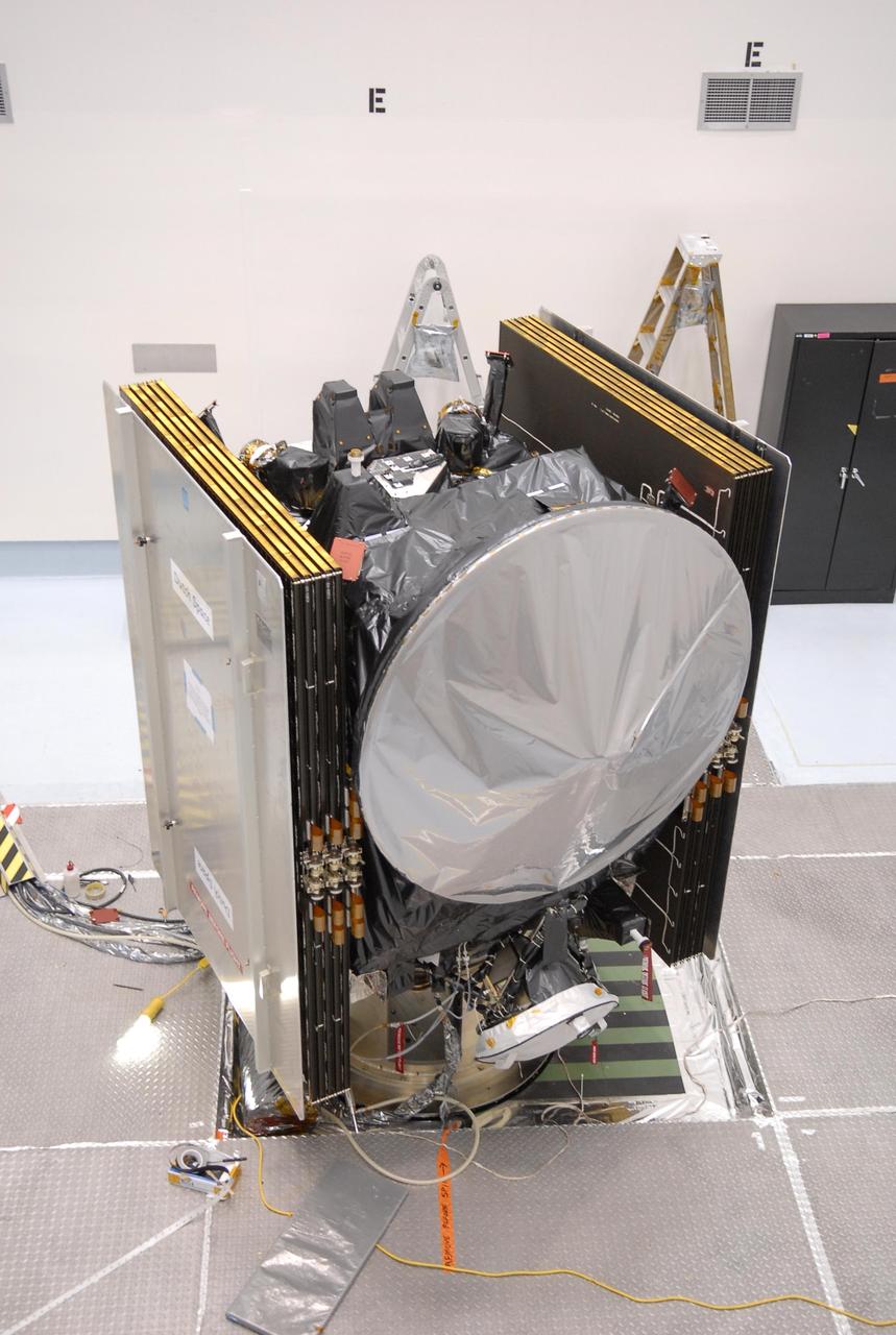
KENNEDY SPACE CENTER, FLA. - In the Payload Hazardous Servicing Facility, technicians prepare the solar arrays for the Mars Reconnaissance Orbiter (MRO) and an antenna simulator (yellow horizontal rod) for an electromagnetic interference verification test. If no interference is found during the test, the Shallow Radar Antenna (SHARAD) will be installed on the spacecraft. The spacecraft is undergoing multiple mechanical assembly operations and electrical tests to verify its readiness for launch. The MRO was built by Lockheed Martin for NASA’s Jet Propulsion Laboratory in California. It is the next major step in Mars exploration and scheduled for launch from Launch Complex 41 at Cape Canaveral Air Force Station in a window opening Aug. 10. The MRO is an important next step in fulfilling NASA’s vision of space exploration and ultimately sending human explorers to Mars and beyond.
KENNEDY SPACE CENTER, FLA. - In the Payload Hazardous Servicing Facility, an electromagnetic interference verification test is being conducted on the solar arrays for the Mars Reconnaissance Orbiter (MRO) and an antenna simulator (yellow horizontal rod). If no interference is found during the test, the Shallow Radar Antenna (SHARAD) will be installed on the spacecraft. The spacecraft is undergoing multiple mechanical assembly operations and electrical tests to verify its readiness for launch. The MRO was built by Lockheed Martin for NASA’s Jet Propulsion Laboratory in California. It is the next major step in Mars exploration and scheduled for launch from Launch Complex 41 at Cape Canaveral Air Force Station in a window opening Aug. 10. The MRO is an important next step in fulfilling NASA’s vision of space exploration and ultimately sending human explorers to Mars and beyond.
KENNEDY SPACE CENTER, FLA. - In the Payload Hazardous Servicing Facility, technicians prepare to conduct an electromagnetic interference verification test using the solar arrays for the Mars Reconnaissance Orbiter (MRO) and an antenna simulator. If no interference is found during the test, the Shallow Radar Antenna (SHARAD) will be installed on the spacecraft. The spacecraft is undergoing multiple mechanical assembly operations and electrical tests to verify its readiness for launch. The MRO was built by Lockheed Martin for NASA’s Jet Propulsion Laboratory in California. It is the next major step in Mars exploration and scheduled for launch from Launch Complex 41 at Cape Canaveral Air Force Station in a window opening Aug. 10. The MRO is an important next step in fulfilling NASA’s vision of space exploration and ultimately sending human explorers to Mars and beyond.
The GOES-L weather satellite sits on a workstand at Astrotech, Titusville, Fla., ready to be encapsulated for its transfer to Launch Pad 36A, Cape Canaveral Air Station. On the left side is the folded, two-panel solar array; on the adjoining side is a white box, which is the UHF antenna. Above the box is the S-band transmit antenna and receive antenna. Between them protrudes a search and rescue antenna. At right are the sounder (top) and imager (bottom). The mounted equipment on top of the unit is a telemetry and command antenna. The GOES is scheduled for launch aboard a Lockheed Martin Atlas II rocket later in May. The fourth of a new advanced series of geostationary weather satellites for the National Oceanic and Atmospheric Administration (NOAA), GOES-L is a three-axis inertially stabilized spacecraft that will provide pictures and perform atmospheric sounding at the same time. After it is launched, the satellite will undergo checkout and then provide backup capabilities for the existing, aging operational satellites. Once in orbit, the satellite will become GOES-11, joining GOES-8, GOES-9 and GOES-10 in space
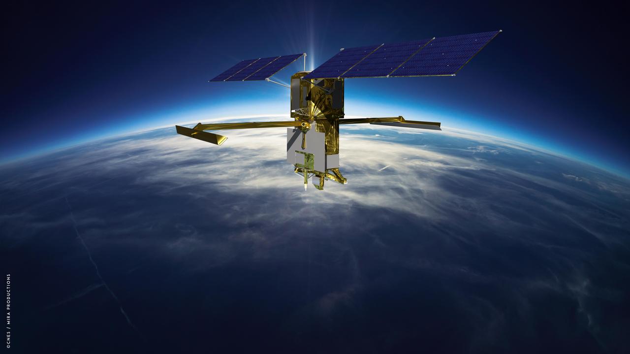
This illustration depicts the Surface Water and Ocean Topography (SWOT) satellite with solar arrays fully deployed. Measuring 48.8 feet (14.9 meters) in length with an area of 335 square feet (31 square meters), the two arrays will remain pointed at the Sun via small motors to provide 8 kilowatts of power; the spacecraft has a 1.5-kilowatt total power demand. The scientific heart of the SWOT satellite is the Ka-band Radar Interferometer (KaRIn) instrument, which will measure the height of water in Earth's lakes, rivers, reservoirs, and ocean. To do that, KaRIn will transmit radar pulses to Earth's surface and use two antennas – seen to the left and right of the spacecraft bus – to triangulate the return signals that bounce back. Mounted at the ends of a boom 33 feet (10 meters) long, the antennas will collect data over two swaths of Earth's surface at a time, each of them 30 miles (50 kilometers) wide and located on either side of the satellite. KaRIn will operate in two modes: A lower-resolution mode over the ocean will involve significant onboard processing of the data to reduce the volume of information sent during downlinks to Earth; a higher-resolution mode will be used mainly over land. https://photojournal.jpl.nasa.gov/catalog/PIA25623
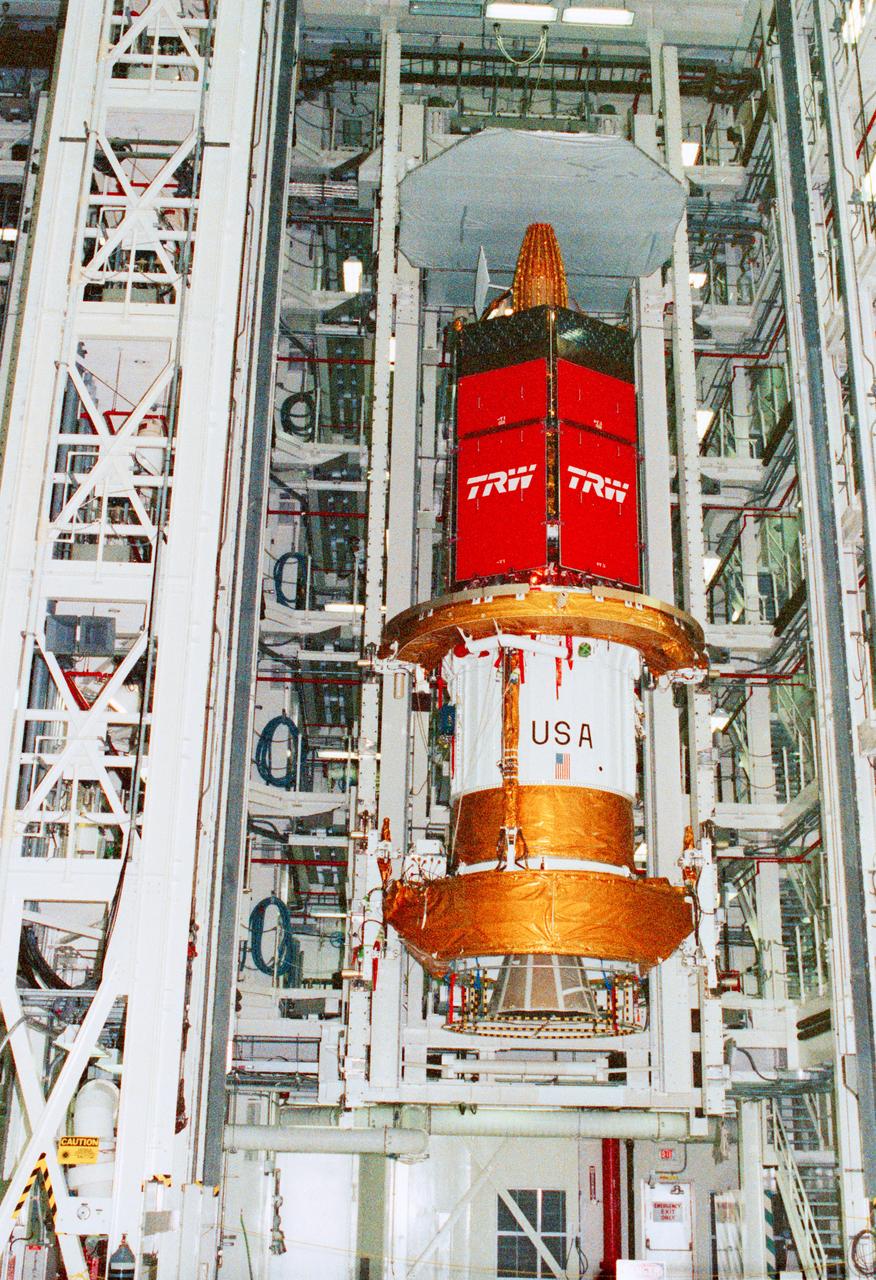
STS-43 Tracking and Data Relay Satellite E (TDRS-E) undergoes preflight processing in the Kennedy Space Center's (KSC's) Vertical Processing Facility (VPF) before being loaded into a payload canister for transfer to the launch pad and eventually into Atlantis', Orbiter Vehicle (OV) 104's, payload bay (PLB). This side of the TDRS-E will rest at the bottom of the PLB therefore the airborne support equipment (ASE) forward frame keel pin (at center of spacecraft) and the umbilical boom running between the two ASE frames are visible. The solar array panels are covered with protective TRW shields. Above the shields the stowed antenna and solar sail are visible. The inertial upper stage (IUS) booster is the white portion of the spacecraft and rests in the ASE forward frame and ASE aft frame tilt actuator (AFTA) frame (at the bottom of the IUS). The IUS booster nozzle extends beyond the AFTA frame. View provided by KSC with alternate number KSC-91PC-1079.

KENNEDY SPACE CENTER, FLA. - At Astrotech Space Operations in Titusville, Fla., engineers install a solar array to one of the two STEREO spacecraft. The dish in front is a high gain antenna. Under black protective wrap at right is the Heliospheric Imager instrument, part of the Sun Earth Connection Coronal and Heliospheric Investigation (SECCHI) package of four instruments that will study the 3-D evolution of coronal mass ejections, from birth at the Sun's surface through the corona and interplanetary medium to its eventual impact at Earth. The long silver cylinder in the front, at right of the antenna, is the In situ Measurements of Particles and CME Transients, known as IMPACT, boom. The red protective covers are removed before flight. STEREO consists of two spacecraft whose mission is the first to take measurements of the sun and solar wind in 3-D. This new view will improve our understanding of space weather and its impact on the Earth. Preparations are under way for a liftoff aboard a Delta rocket no earlier than July 22. Photo credit: NASA/George Shelton

KENNEDY SPACE CENTER, FLA. - At Astrotech Space Operations in Titusville, Fla., engineers install a solar array to one of the two STEREO spacecraft. The dish in front is a high gain antenna. Under black protective wrap at right is the Sun Earth Connection Coronal and Heliospheric Investigation (SECCHI) package of four instruments that will study the 3-D evolution of coronal mass ejections, from birth at the Sun's surface through the corona and interplanetary medium to its eventual impact at Earth. The long silver cylinder in the front, at right of the antenna, is the In situ Measurements of Particles and CME Transients, known as IMPACT, boom. The red protective covers are removed before flight. STEREO consists of two spacecraft whose mission is the first to take measurements of the sun and solar wind in 3-D. This new view will improve our understanding of space weather and its impact on the Earth. Preparations are under way for a liftoff aboard a Delta rocket no earlier than July 22. Photo credit: NASA/George Shelton

KENNEDY SPACE CENTER, FLA. - At Astrotech Space Operations in Titusville, Fla., engineers install a solar array to one of the two STEREO spacecraft. The dish in front is the high gain antenna. Under black protective wrap at right is the Heliospheric Imager instrument, part of the Sun Earth Connection Coronal and Heliospheric Investigation (SECCHI) package of four instruments that will study the 3-D evolution of coronal mass ejections, from birth at the Sun's surface through the corona and interplanetary medium to its eventual impact at Earth. The long silver cylinder in the front, at right of the antenna, is the In situ Measurements of Particles and CME Transients, known as IMPACT, boom. The red protective covers are removed before flight. STEREO consists of two spacecraft whose mission is the first to take measurements of the sun and solar wind in 3-D. This new view will improve our understanding of space weather and its impact on the Earth. Preparations are under way for a liftoff aboard a Delta rocket no earlier than July 22. Photo credit: NASA/George Shelton
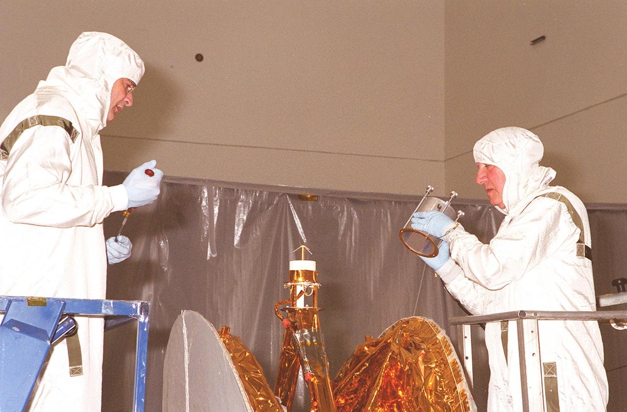
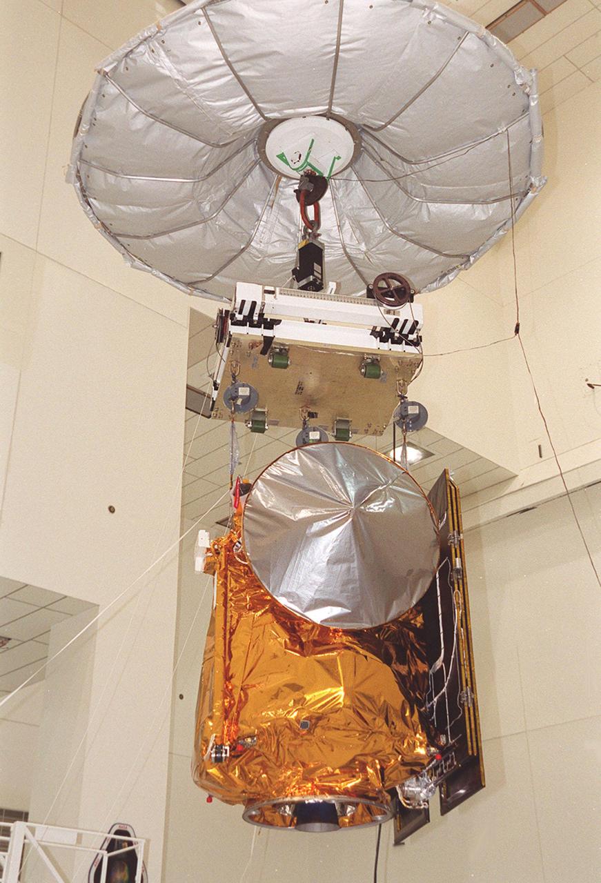
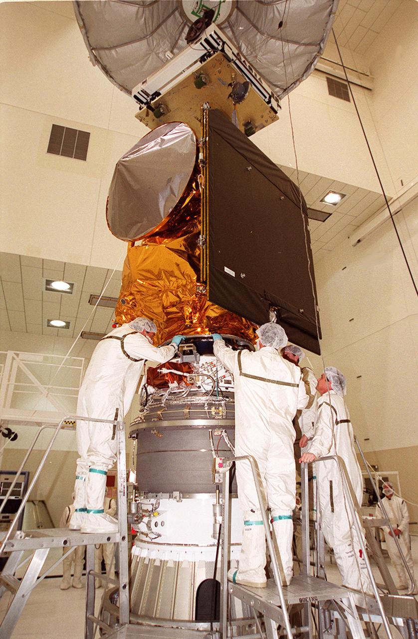
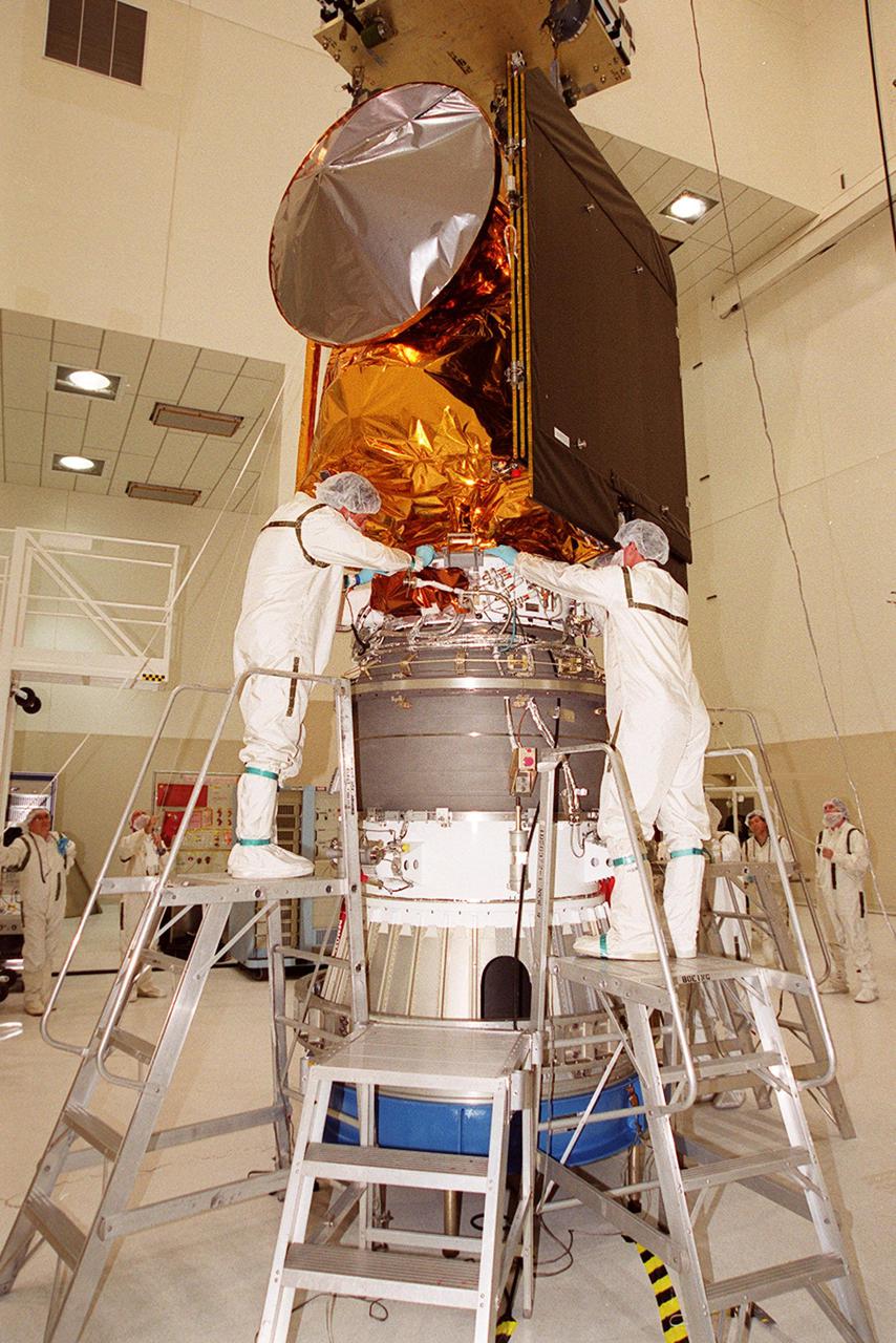
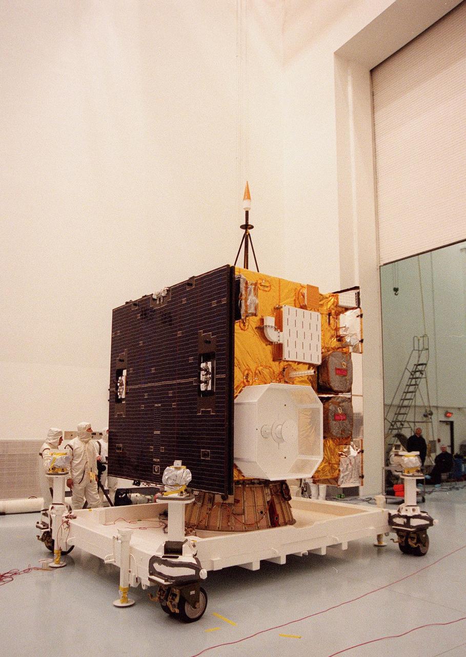
KENNEDY SPACE CENTER, FLA. -- Workers in the Spacecraft Assembly and Encapsulation Facility 2 place an antenna on the Microwave Anisotropy Probe (MAP). Several other milestones must be completed while MAP is at SAEF-2, including solar array installation, solar array deployment and illumination testing, a spacecraft comprehensive performance test, fueling with hydrazine propellant and a spin balance test. MAP will then be ready for integration with the solid propellant Payload Assist Module upper stage booster. MAP is scheduled for launch June 30 from Cape Canaveral Air Force Station on a Delta II rocket into a lunar-assisted trajectory to the Sun-Earth for a 27-month mission. The MAP instrument consists of a set of passively cooled microwave radiometers with 1.4x 1.6-meter diameter primary reflectors to provide the desired angular resolution. MAP measures small fluctuations in the temperature of the cosmic microwave background radiation to an accuracy of one millionth of a degree These measurements should reveal the size, matter content, age, geometry and fate of the universe. They will also reveal the primordial structure that grew to form galaxies and will test ideas about the origins of these primordial structures. The MAP instrument will be continuously shaded from the Sun, Earth, and Moon by the spacecraft. It is a product of Goddard Space Flight Center in partnership with Princeton University
KENNEDY SPACE CENTER, FLA. -- The Microwave Anisotropy Probe (MAP) is worked on in the Spacecraft Assembly and Encapsulation Facility 2. Several milestones must be completed while MAP is at SAEF-2, including antenna installations, solar array installation, solar array deployment and illumination testing, a spacecraft comprehensive performance test, fueling with hydrazine propellant and a spin balance test. MAP will then be ready for integration with the solid propellant Payload Assist Module upper stage booster. MAP is scheduled for launch June 30 from Cape Canaveral Air Force Station on a Delta II rocket into a lunar-assisted trajectory to the Sun-Earth for a 27-month mission. The MAP instrument consists of a set of passively cooled microwave radiometers with 1.4x 1.6-meter diameter primary reflectors to provide the desired angular resolution. MAP measures small fluctuations in the temperature of the cosmic microwave background radiation to an accuracy of one millionth of a degree These measurements should reveal the size, matter content, age, geometry and fate of the universe. They will also reveal the primordial structure that grew to form galaxies and will test ideas about the origins of these primordial structures. The MAP instrument will be continuously shaded from the Sun, Earth, and Moon by the spacecraft. It is a product of Goddard Space Flight Center in partnership with Princeton University
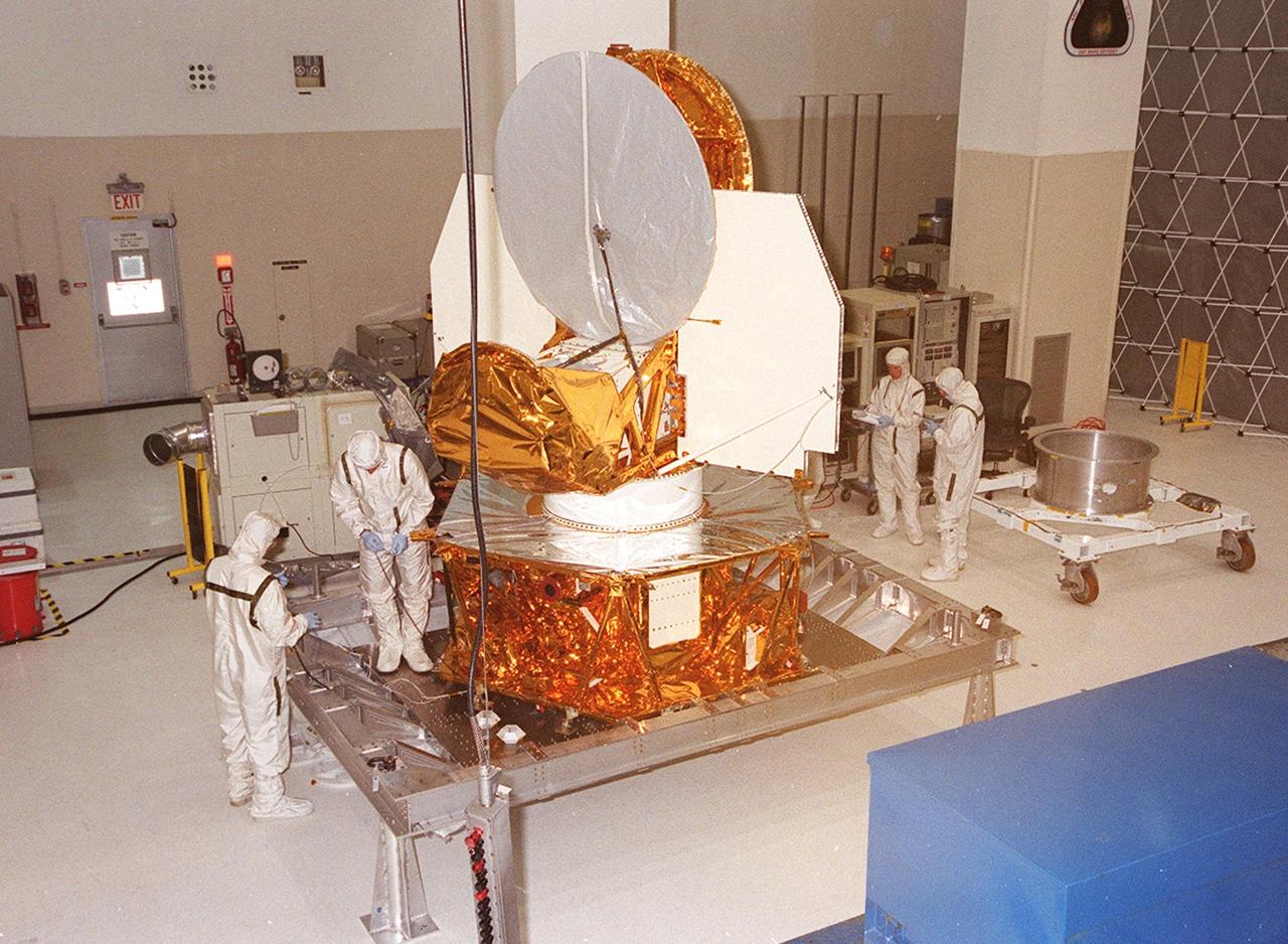
KENNEDY SPACE CENTER, FLA. -- In the Spacecraft Assembly and Encapsulation Facility 2, workers check out parts of the Microwave Anisotropy Probe (MAP. Several milestones must be completed while MAP is at SAEF-2, including antenna and solar array installation, solar array deployment and illumination testing, a spacecraft comprehensive performance test, fueling with hydrazine propellant and a spin balance test. MAP will then be ready for integration with the solid propellant Payload Assist Module upper stage booster. MAP is scheduled for launch June 30 from Cape Canaveral Air Force Station on a Delta II rocket into a lunar-assisted trajectory to the Sun-Earth for a 27-month mission. The MAP instrument consists of a set of passively cooled microwave radiometers with 1.4x 1.6-meter diameter primary reflectors to provide the desired angular resolution. MAP measures small fluctuations in the temperature of the cosmic microwave background radiation to an accuracy of one millionth of a degree These measurements should reveal the size, matter content, age, geometry and fate of the universe. They will also reveal the primordial structure that grew to form galaxies and will test ideas about the origins of these primordial structures. The MAP instrument will be continuously shaded from the Sun, Earth, and Moon by the spacecraft. It is a product of Goddard Space Flight Center in partnership with Princeton University
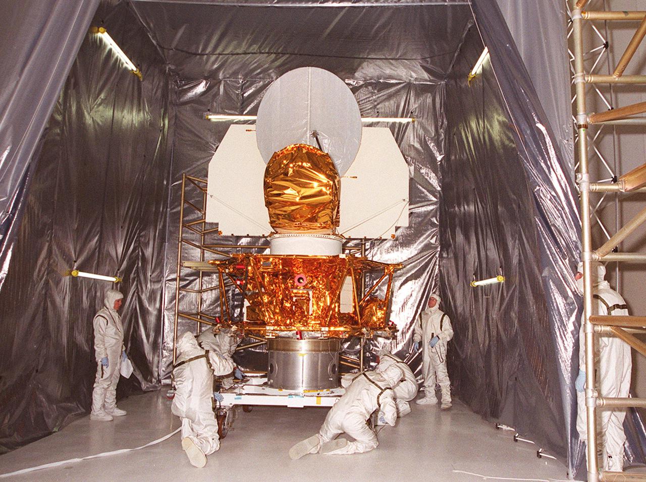
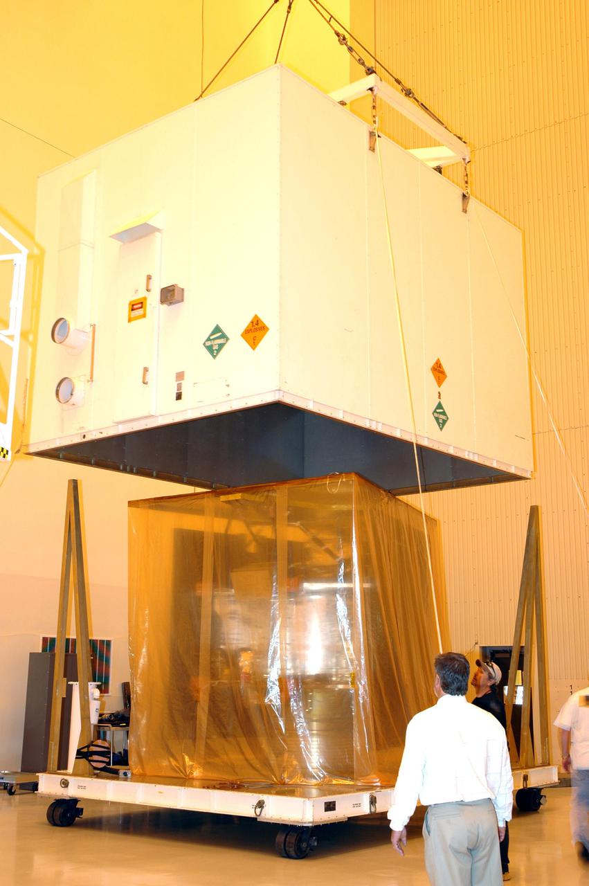
KENNEDY SPACE CENTER, FLA. -- Workers in the Spacecraft Assembly and Encapsulation Facility 2 secure the Microwave Anisotropy Probe (MAP) on a workstand inside a tent. Several milestones must be completed while MAP is at SAEF-2, including antenna installations, solar array installation, solar array deployment and illumination testing, a spacecraft comprehensive performance test, fueling with hydrazine propellant and a spin balance test. MAP will then be ready for integration with the solid propellant Payload Assist Module upper stage booster. MAP is scheduled for launch June 30 from Cape Canaveral Air Force Station on a Delta II rocket into a lunar-assisted trajectory to the Sun-Earth for a 27-month mission. The MAP instrument consists of a set of passively cooled microwave radiometers with 1.4x 1.6-meter diameter primary reflectors to provide the desired angular resolution. MAP measures small fluctuations in the temperature of the cosmic microwave background radiation to an accuracy of one millionth of a degree These measurements should reveal the size, matter content, age, geometry and fate of the universe. They will also reveal the primordial structure that grew to form galaxies and will test ideas about the origins of these primordial structures. The MAP instrument will be continuously shaded from the Sun, Earth, and Moon by the spacecraft. It is a product of Goddard Space Flight Center in partnership with Princeton University

KENNEDY SPACE CENTER, FLA. -- In the Spacecraft Assembly and Encapsulation Facility 2, the Microwave Anisotropy Probe (MAP) undergoes testing and checkout. Several milestones must be completed while MAP is at SAEF-2, including antenna and solar array installation, solar array deployment and illumination testing, a spacecraft comprehensive performance test, fueling with hydrazine propellant and a spin balance test. MAP will then be ready for integration with the solid propellant Payload Assist Module upper stage booster. MAP is scheduled for launch June 30 from Cape Canaveral Air Force Station on a Delta II rocket into a lunar-assisted trajectory to the Sun-Earth for a 27-month mission. The MAP instrument consists of a set of passively cooled microwave radiometers with 1.4x 1.6-meter diameter primary reflectors to provide the desired angular resolution. MAP measures small fluctuations in the temperature of the cosmic microwave background radiation to an accuracy of one millionth of a degree These measurements should reveal the size, matter content, age, geometry and fate of the universe. They will also reveal the primordial structure that grew to form galaxies and will test ideas about the origins of these primordial structures. The MAP instrument will be continuously shaded from the Sun, Earth, and Moon by the spacecraft. It is a product of Goddard Space Flight Center in partnership with Princeton University
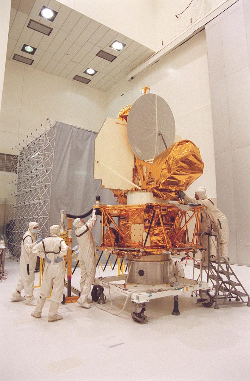
KENNEDY SPACE CENTER, FLA. -- Workers in the Spacecraft Assembly and Encapsulation Facility 2 stand by while the Microwave Anisotropy Probe (MAP) is lifted to place it on a workstand. Several milestones must be completed while MAP is at SAEF-2, including antenna installations, solar array installation, solar array deployment and illumination testing, a spacecraft comprehensive performance test, fueling with hydrazine propellant and a spin balance test. MAP will then be ready for integration with the solid propellant Payload Assist Module upper stage booster. MAP is scheduled for launch June 30 from Cape Canaveral Air Force Station on a Delta II rocket into a lunar-assisted trajectory to the Sun-Earth for a 27-month mission. The MAP instrument consists of a set of passively cooled microwave radiometers with 1.4x 1.6-meter diameter primary reflectors to provide the desired angular resolution. MAP measures small fluctuations in the temperature of the cosmic microwave background radiation to an accuracy of one millionth of a degree These measurements should reveal the size, matter content, age, geometry and fate of the universe. They will also reveal the primordial structure that grew to form galaxies and will test ideas about the origins of these primordial structures. The MAP instrument will be continuously shaded from the Sun, Earth, and Moon by the spacecraft. It is a product of Goddard Space Flight Center in partnership with Princeton University
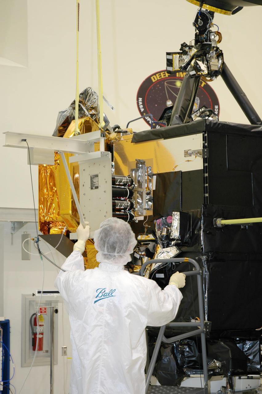
KENNEDY SPACE CENTER, FLA. - At Astrotech Space Operations in Titusville, Fla., a Ball Aerospace technician helps guide the flight battery toward the flyby spacecraft on Deep Impact where it will be installed. About the size of a Ford Explorer, the flyby spacecraft is three-axis stabilized and uses a fixed solar array and a small NiH2 battery for its power system. A NASA Discovery mission, Deep Impact will probe beneath the surface of Comet Tempel 1 on July 4, 2005, when the comet is 83 million miles from Earth. During the encounter phase when the comet collides with the impactor projectile propelled into its path, the spacecraft’s high-gain antenna will transmit near-real-time images of the impact back to Earth. The spacecraft is scheduled to launch Jan. 8 aboard a Boeing Delta II rocket from Launch Complex 17-B at Cape Canaveral Air Force Station, Fla.
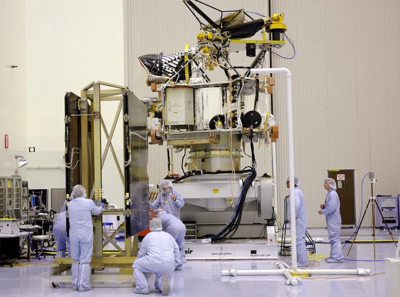
KENNEDY SPACE CENTER, FLA. - Inside the Payload Hazardous Servicing Facility (PHSF) at NASA's Kennedy Space Center, the cover is removed from one of the boxes containing NASA's Mars Reconnaissance Orbiter. Here in the PHSF, the spacecraft will undergo multiple mechanical assembly operations and electrical tests to verify its readiness for launch. A test this month will verify the spacecraft's ability to communicate through NASA's Deep Space Network tracking stations. A June test will check the deployment of the spacecraft's high gain communications antenna. Another major deployment test will check out the spacecraft's large solar arrays. The MRO was built by Lockheed Martin for NASA's Jet Propulsion Laboratory in California. It is the next major step in Mars exploration and scheduled for launch from Cape Canaveral Air Force Station in a window opening Aug. 10. The MRO is an important next step in fulfilling NASA's vision of space exploration and ultimately sending human explorers to Mars and beyond.
KENNEDY SPACE CENTER, FLA. - In a clean room inside the Payload Hazardous Servicing Facility (PHSF) at NASA’s Kennedy Space Center, the suspended Mars Reconnaissance Orbiter (MRO) nears the workstand in the background for final assembly and testing. In the PHSF, the spacecraft will undergo multiple mechanical assembly operations and electrical tests to verify its readiness for launch. A test this month will verify the spacecraft’s ability to communicate through NASA's Deep Space Network tracking stations. A June test will check the deployment of the spacecraft's high gain communications antenna. Another major deployment test will check out the spacecraft's large solar arrays. The MRO was built for NASA’s Jet Propulsion Laboratory in California. It is the next major step in Mars exploration and scheduled for launch from Cape Canaveral Air Force Station in a window opening Aug. 10. The MRO is an important next step in fulfilling NASA’s vision of space exploration and ultimately sending human explorers to Mars and beyond.
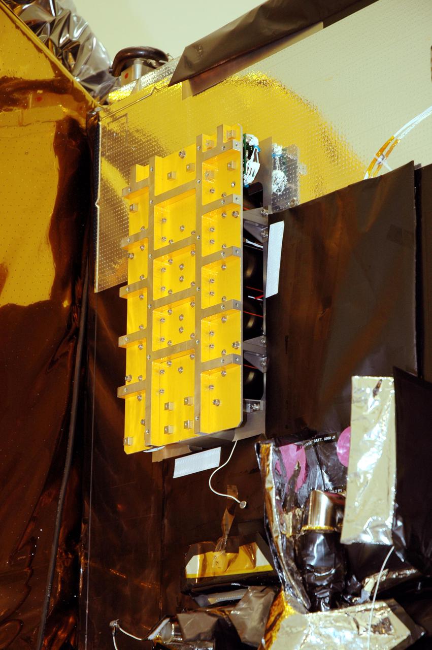
KENNEDY SPACE CENTER, FLA. - At Astrotech Space Operations in Titusville, Fla., the flight battery has been installed on the Deep Impact flyby spacecraft. About the size of a Ford Explorer, the flyby spacecraft is three-axis stabilized and uses a fixed solar array and a small NiH2 battery for its power system. A NASA Discovery mission, Deep Impact will probe beneath the surface of Comet Tempel 1 on July 4, 2005, when the comet is 83 million miles from Earth. During the encounter phase when the comet collides with the impactor projectile propelled into its path, the spacecraft’s high-gain antenna will transmit near-real-time images of the impact back to Earth. The spacecraft is scheduled to launch Jan. 8 aboard a Boeing Delta II rocket from Launch Complex 17-B at Cape Canaveral Air Force Station, Fla.
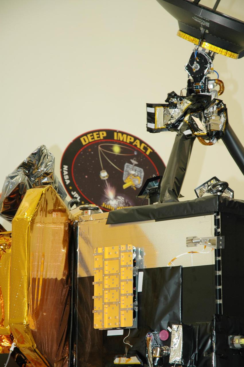
KENNEDY SPACE CENTER, FLA. - At Astrotech Space Operations in Titusville, Fla., the flight battery has been installed on the Deep Impact flyby spacecraft. About the size of a Ford Explorer, the flyby spacecraft is three-axis stabilized and uses a fixed solar array and a small NiH2 battery for its power system. A NASA Discovery mission, Deep Impact will probe beneath the surface of Comet Tempel 1 on July 4, 2005, when the comet is 83 million miles from Earth. During the encounter phase when the comet collides with the impactor projectile propelled into its path, the spacecraft’s high-gain antenna will transmit near-real-time images of the impact back to Earth. The spacecraft is scheduled to launch Jan. 8 aboard a Boeing Delta II rocket from Launch Complex 17-B at Cape Canaveral Air Force Station, Fla.

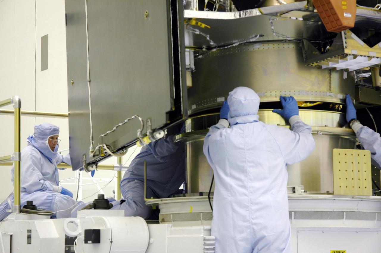
KENNEDY SPACE CENTER, FLA. - Ball Aerospace technicians prepare the Deep Impact flyby spacecraft for installation of the flight battery at Astrotech Space Operations in Titusville, Fla. About the size of a Ford Explorer, the flyby spacecraft is three-axis stabilized and uses a fixed solar array and a small NiH2 battery for its power system. A NASA Discovery mission, Deep Impact will probe beneath the surface of Comet Tempel 1 on July 4, 2005, when the comet is 83 million miles from Earth. During the encounter phase when the comet collides with the impactor projectile propelled into its path, the spacecraft’s high-gain antenna will transmit near-real-time images of the impact back to Earth. The spacecraft is scheduled to launch Jan. 8 aboard a Boeing Delta II rocket from Launch Complex 17-B at Cape Canaveral Air Force Station, Fla.
KENNEDY SPACE CENTER, FLA. - In a clean room inside the Payload Hazardous Servicing Facility (PHSF) at NASA's Kennedy Space Center, Lockheed Martin workers help guide the Mars Reconnaissance Orbiter onto the workstand for final assembly and testing. In the PHSF, the spacecraft will undergo multiple mechanical assembly operations and electrical tests to verify its readiness for launch. A test this month will verify the spacecraft's ability to communicate through NASA's Deep Space Network tracking stations. A June test will check the deployment of the spacecraft's high gain communications antenna. Another major deployment test will check out the spacecraft's large solar arrays. The MRO was built for NASA's Jet Propulsion Laboratory in California. It is the next major step in Mars exploration and scheduled for launch from Cape Canaveral Air Force Station in a window opening Aug. 10. The MRO is an important next step in fulfilling NASA's vision of space exploration and ultimately sending human explorers to Mars and beyond.
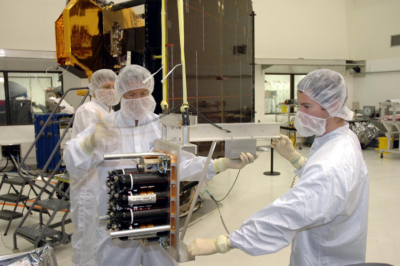
KENNEDY SPACE CENTER, FLA. - Ball Aerospace technicians at Astrotech Space Operations in Titusville, Fla., attach equipment to the flight battery to move it to the Deep Impact flyby spacecraft for installation. About the size of a Ford Explorer, the flyby spacecraft is three-axis stabilized and uses a fixed solar array and a small NiH2 battery for its power system. A NASA Discovery mission, Deep Impact will probe beneath the surface of Comet Tempel 1 on July 4, 2005, when the comet is 83 million miles from Earth. During the encounter phase when the comet collides with the impactor projectile propelled into its path, the spacecraft’s high-gain antenna will transmit near-real-time images of the impact back to Earth. The spacecraft is scheduled to launch Jan. 8 aboard a Boeing Delta II rocket from Launch Complex 17-B at Cape Canaveral Air Force Station, Fla.
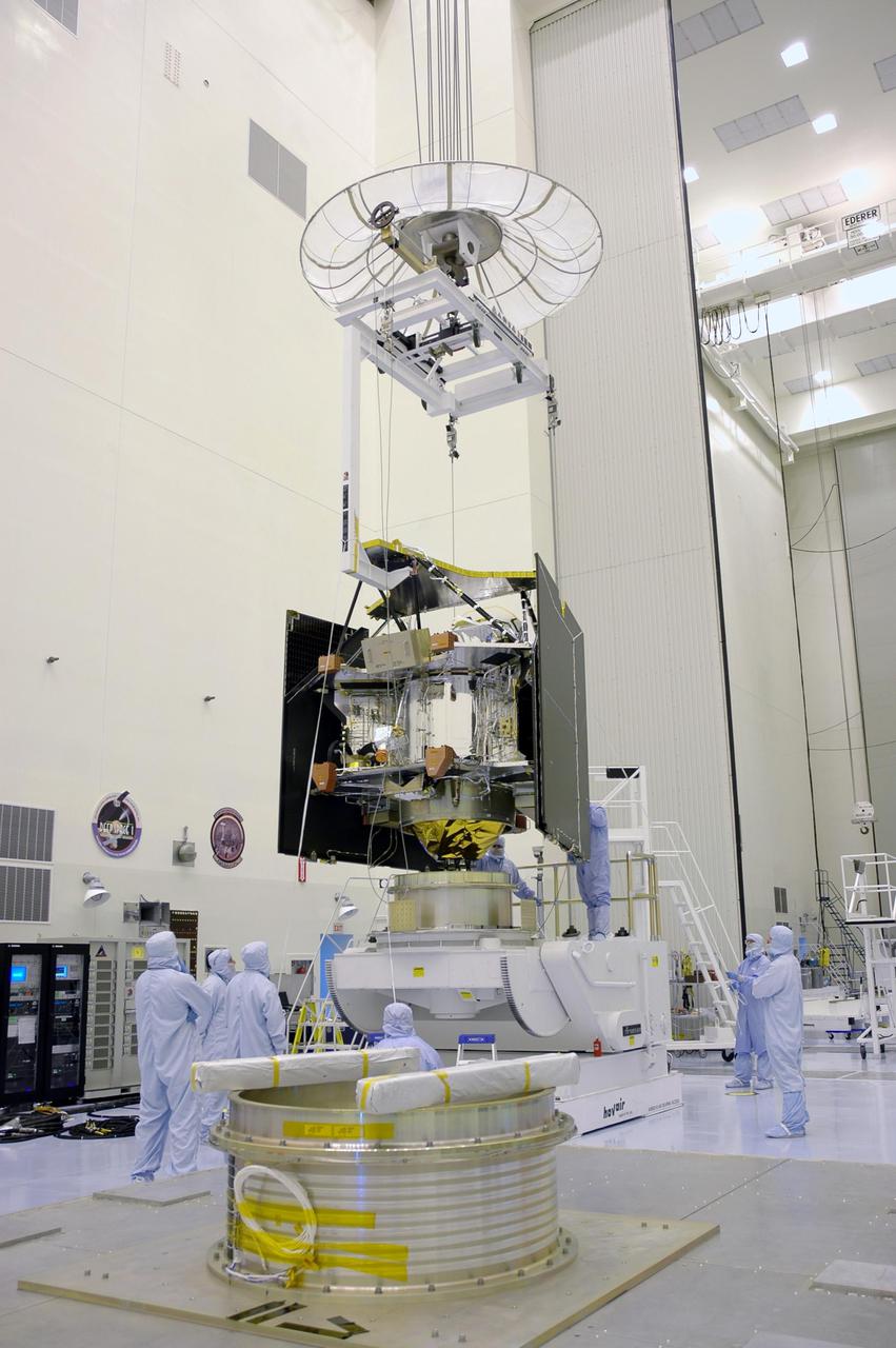
KENNEDY SPACE CENTER, FLA. -In a clean room inside the Payload Hazardous Servicing Facility (PHSF) at NASA’s Kennedy Space Center, the Mars Reconnaissance Orbiter (MRO) is lifted by an overhead crane to move it to a nearby workstand for final assembly and testing. In the PHSF, the spacecraft will undergo multiple mechanical assembly operations and electrical tests to verify its readiness for launch. A test this month will verify the spacecraft’s ability to communicate through NASA's Deep Space Network tracking stations. A June test will check the deployment of the spacecraft's high gain communications antenna. Another major deployment test will check out the spacecraft's large solar arrays. The MRO was built for NASA’s Jet Propulsion Laboratory in California. It is the next major step in Mars exploration and scheduled for launch from Cape Canaveral Air Force Station in a window opening Aug. 10. The MRO is an important next step in fulfilling NASA’s vision of space exploration and ultimately sending human explorers to Mars and beyond.
KENNEDY SPACE CENTER, FLA. - Ball Aerospace technicians check the flight battery for the Deep Impact flyby spacecraft before installation at Astrotech Space Operations in Titusville, Fla. About the size of a Ford Explorer, the flyby spacecraft is three-axis stabilized and uses a fixed solar array and a small NiH2 battery for its power system. A NASA Discovery mission, Deep Impact will probe beneath the surface of Comet Tempel 1 on July 4, 2005, when the comet is 83 million miles from Earth. During the encounter phase when the comet collides with the impactor projectile propelled into its path, the spacecraft’s high-gain antenna will transmit near-real-time images of the impact back to Earth. The spacecraft is scheduled to launch Jan. 8 aboard a Boeing Delta II rocket from Launch Complex 17-B at Cape Canaveral Air Force Station, Fla.
KENNEDY SPACE CENTER, FLA. - In a clean room inside the Payload Hazardous Servicing Facility (PHSF) at NASA's Kennedy Space Center, Lockheed Martin workers assure the Mars Reconnaissance Orbiter is secure on its workstand for final assembly and testing. In the PHSF, the spacecraft will undergo multiple mechanical assembly operations and electrical tests to verify its readiness for launch. A test this month will verify the spacecraft's ability to communicate through NASA's Deep Space Network tracking stations. A June test will check the deployment of the spacecraft's high gain communications antenna. Another major deployment test will check out the spacecraft's large solar arrays. The MRO was built for NASA's Jet Propulsion Laboratory in California. It is the next major step in Mars exploration and scheduled for launch from Cape Canaveral Air Force Station in a window opening Aug. 10. The MRO is an important next step in fulfilling NASA's vision of space exploration and ultimately sending human explorers to Mars and beyond.
KENNEDY SPACE CENTER, FLA. - In a clean room inside the Payload Hazardous Servicing Facility (PHSF) at NASA's Kennedy Space Center, removal of the protective cover reveals some of the hardware for NASA's Mars Reconnaissance Orbiter. Here in the PHSF, the spacecraft will undergo multiple mechanical assembly operations and electrical tests to verify its readiness for launch. A test this month will verify the spacecraft's ability to communicate through NASA's Deep Space Network tracking stations. A June test will check the deployment of the spacecraft's high gain communications antenna. Another major deployment test will check out the spacecraft's large solar arrays. The MRO was built by Lockheed Martin for NASA's Jet Propulsion Laboratory in California. It is the next major step in Mars exploration and scheduled for launch from Cape Canaveral Air Force Station in a window opening Aug. 10. The MRO is an important next step in fulfilling NASA's vision of space exploration and ultimately sending human explorers to Mars and beyond.
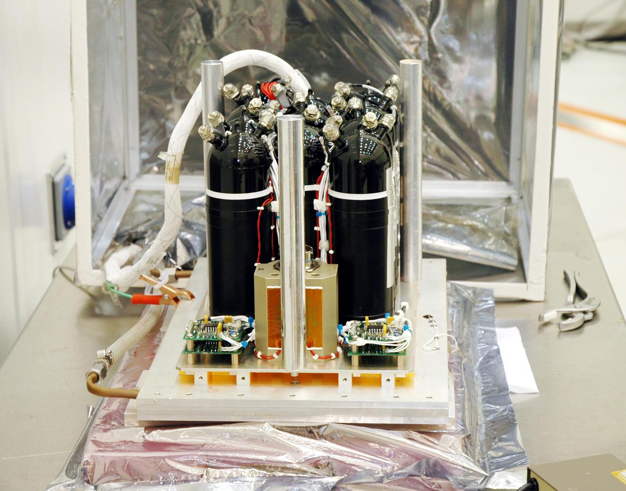
KENNEDY SPACE CENTER, FLA. - The flight battery for the Deep Impact flyby spacecraft awaits installation at Astrotech Space Operations in Titusville, Fla. About the size of a Ford Explorer, the flyby spacecraft is three-axis stabilized and uses a fixed solar array and a small NiH2 battery for its power system. A NASA Discovery mission, Deep Impact will probe beneath the surface of Comet Tempel 1 on July 4, 2005, when the comet is 83 million miles from Earth. During the encounter phase when the comet collides with the impactor projectile propelled into its path, the spacecraft’s high-gain antenna will transmit near-real-time images of the impact back to Earth. The spacecraft is scheduled to launch Jan. 8 aboard a Boeing Delta II rocket from Launch Complex 17-B at Cape Canaveral Air Force Station, Fla.
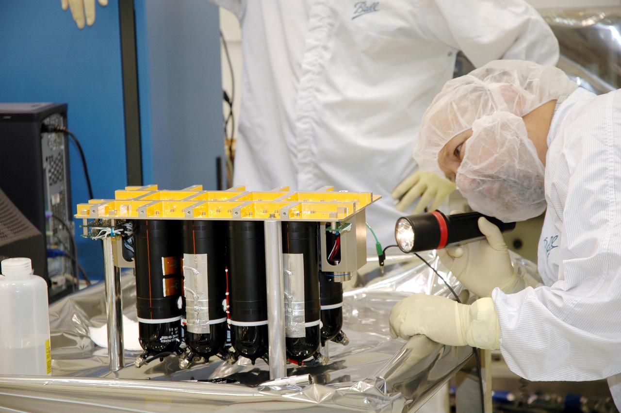
KENNEDY SPACE CENTER, FLA. - Ball Aerospace technicians at Astrotech Space Operations in Titusville, Fla., take a final look at the flight battery before moving and installing it on the Deep Impact flyby spacecraft. About the size of a Ford Explorer, the flyby spacecraft is three-axis stabilized and uses a fixed solar array and a small NiH2 battery for its power system. A NASA Discovery mission, Deep Impact will probe beneath the surface of Comet Tempel 1 on July 4, 2005, when the comet is 83 million miles from Earth. During the encounter phase when the comet collides with the impactor projectile propelled into its path, the spacecraft’s high-gain antenna will transmit near-real-time images of the impact back to Earth. The spacecraft is scheduled to launch Jan. 8 aboard a Boeing Delta II rocket from Launch Complex 17-B at Cape Canaveral Air Force Station, Fla.
KENNEDY SPACE CENTER, FLA. - In the Payload Hazardous Servicing Facility, a technician prepares the solar arrays for the Mars Reconnaissance Orbiter (MRO) for an electromagnetic interference verification test. If no interference is found during the test, the Shallow Radar Antenna (SHARAD) will be installed on the spacecraft. The spacecraft is undergoing multiple mechanical assembly operations and electrical tests to verify its readiness for launch. The MRO was built by Lockheed Martin for NASA’s Jet Propulsion Laboratory in California. It is the next major step in Mars exploration and scheduled for launch from Launch Complex 41 at Cape Canaveral Air Force Station in a window opening Aug. 10. The MRO is an important next step in fulfilling NASA’s vision of space exploration and ultimately sending human explorers to Mars and beyond.
KENNEDY SPACE CENTER, FLA. - In the Payload Hazardous Servicing Facility, technicians position the solar arrays for the Mars Reconnaissance Orbiter (MRO) in preparation for an electromagnetic interference verification test. If no interference is found during the test, the Shallow Radar Antenna (SHARAD) will be installed on the spacecraft. The spacecraft is undergoing multiple mechanical assembly operations and electrical tests to verify its readiness for launch. The MRO was built by Lockheed Martin for NASA’s Jet Propulsion Laboratory in California. It is the next major step in Mars exploration and scheduled for launch from Launch Complex 41 at Cape Canaveral Air Force Station in a window opening Aug. 10. The MRO is an important next step in fulfilling NASA’s vision of space exploration and ultimately sending human explorers to Mars and beyond.
KENNEDY SPACE CENTER, FLA. - At Astrotech Space Operations in Titusville, Fla., the two STEREO spacecraft are being prepared for installation of the solar arrays. In the foreground is spacecraft "B," sitting as it would on the rocket. Pointing to the right is the high gain antenna (HGA), which is used to get science data at high data rates back to Earth. In the background is the "A" observatory, rotated horizontally on a Ransome table so that its HGA is pointing upward. The black circle facing forward is the primary instrument Sun Earth Connection Coronal and Heliospheric Investigation (SECCHI), a suite of remote sensing instruments to image solar flares, with a protective cover that is removed before flight. STEREO consists of two spacecraft whose mission is the first to take measurements of the sun and solar wind in 3-D. This new view will improve our understanding of space weather and its impact on the Earth. Preparations are under way for a liftoff aboard a Delta rocket no earlier than July 22. Photo credit: NASA/George Shelton
This video animation shows antennas for the Ka-band Radar Interferometer (KaRIn) instrument deploying on the Surface Water and Ocean Topography (SWOT) satellite. KaRIn is the scientific heart of the spacecraft, which launched into Earth orbit on Friday, Dec. 16, 2022, from Vandenberg Space Force Base in central California. SWOT will measure the height of water on over 90% of Earth's surface, providing a high-definition survey of our planet's water for the first time. But before it can do that, engineers need to deploy the satellite's solar panel arrays, which power the spacecraft, and unfold the large mast and antenna panels for the KaRIn instrument. The mast and antenna deployment is a four-day process. Thirty-three feet (10 meters) apart, at either end of the mast, the two antennas are designed to capture precise measurements of the height of water in Earth's freshwater bodies and the ocean. KaRIn will see eddies, currents, and other ocean features less than 13 miles (20 kilometers) across, and it will collect data on lakes and reservoirs larger than 15 acres (62,500 square meters) and rivers wider than 330 feet (100 meters) across. KaRIn will do this by bouncing radar pulses off the surface of the water and receiving the return signals with both of those antennas, collecting data along a swath on the surface that's 30 miles (50 kilometers) wide on either side of the satellite. The data SWOT provides will help researchers and decision-makers address some of the most pressing climate questions of our time and help communities prepare for a warming world. Animation available at https://photojournal.jpl.nasa.gov/catalog/PIA25596

KENNEDY SPACE CENTER, FLA. - In the Payload Hazardous Servicing Facility at NASA’s Kennedy Space Center, workers from Lockheed Martin help raise the high-gain antenna vertically for installation on the Mars Reconnaissance Orbiter (MRO). After solar array installation, the MRO will be transported to the Vertical Installation Facility in late July. It will join the Atlas V for the final phase of launch preparations. The spacecraft is then scheduled to undergo a functional test, and a final week of integrated testing and closeouts. The MRO was built by Lockheed Martin for the Jet Propulsion Laboratory in California. It is the next major step in Mars exploration and scheduled for launch from Cape Canaveral Air Force Station in a window opening Aug. 10. The MRO is an important next step in fulfilling NASA’s vision of space exploration and ultimately sending human explorers to Mars and beyond.
KENNEDY SPACE CENTER, FLA. - In the Payload Hazardous Servicing Facility at NASA’s Kennedy Space Center, workers from Lockheed Martin test the installation of the high-gain antenna on the Mars Reconnaissance Orbiter (MRO). After solar array installation, the MRO will be transported to the Vertical Installation Facility in late July. It will join the Atlas V for the final phase of launch preparations. The spacecraft is then scheduled to undergo a functional test, and a final week of integrated testing and closeouts. The MRO was built by Lockheed Martin for the Jet Propulsion Laboratory in California. It is the next major step in Mars exploration and scheduled for launch from Cape Canaveral Air Force Station in a window opening Aug. 10. The MRO is an important next step in fulfilling NASA’s vision of space exploration and ultimately sending human explorers to Mars and beyond.
KENNEDY SPACE CENTER, FLA. - In the Payload Hazardous Servicing Facility at NASA’s Kennedy Space Center, workers from Lockheed Martin prepare the high-gain antenna for installation on the Mars Reconnaissance Orbiter (MRO), in the background. After solar array installation, the MRO will be transported to the Vertical Installation Facility in late July. It will join the Atlas V for the final phase of launch preparations. The spacecraft is then scheduled to undergo a functional test, and a final week of integrated testing and closeouts. The MRO was built by Lockheed Martin for the Jet Propulsion Laboratory in California. It is the next major step in Mars exploration and scheduled for launch from Cape Canaveral Air Force Station in a window opening Aug. 10. The MRO is an important next step in fulfilling NASA’s vision of space exploration and ultimately sending human explorers to Mars and beyond.

KENNEDY SPACE CENTER, FLA. - In the Payload Hazardous Servicing Facility at NASA’s Kennedy Space Center, workers from Lockheed Martin help guide the high-gain antenna toward the Mars Reconnaissance Orbiter (MRO) for installation. After solar array installation, the MRO will be transported to the Vertical Installation Facility in late July. It will join the Atlas V for the final phase of launch preparations. The spacecraft is then scheduled to undergo a functional test, and a final week of integrated testing and closeouts. The MRO was built by Lockheed Martin for the Jet Propulsion Laboratory in California. It is the next major step in Mars exploration and scheduled for launch from Cape Canaveral Air Force Station in a window opening Aug. 10. The MRO is an important next step in fulfilling NASA’s vision of space exploration and ultimately sending human explorers to Mars and beyond.

KENNEDY SPACE CENTER, FLA. - In the Payload Hazardous Servicing Facility at NASA’s Kennedy Space Center, workers from Lockheed Martin prepare the high-gain antenna for installation on the Mars Reconnaissance Orbiter (MRO). After solar array installation, the MRO will be transported to the Vertical Installation Facility in late July. It will join the Atlas V for the final phase of launch preparations. The spacecraft is then scheduled to undergo a functional test, and a final week of integrated testing and closeouts. The MRO was built by Lockheed Martin for the Jet Propulsion Laboratory in California. It is the next major step in Mars exploration and scheduled for launch from Cape Canaveral Air Force Station in a window opening Aug. 10. The MRO is an important next step in fulfilling NASA’s vision of space exploration and ultimately sending human explorers to Mars and beyond.

KENNEDY SPACE CENTER, FLA. - In the Payload Hazardous Servicing Facility at NASA’s Kennedy Space Center, workers from Lockheed Martin begin installing the high-gain antenna on the Mars Reconnaissance Orbiter (MRO). After solar array installation, the MRO will be transported to the Vertical Installation Facility in late July. It will join the Atlas V for the final phase of launch preparations. The spacecraft is then scheduled to undergo a functional test, and a final week of integrated testing and closeouts. The MRO was built by Lockheed Martin for the Jet Propulsion Laboratory in California. It is the next major step in Mars exploration and scheduled for launch from Cape Canaveral Air Force Station in a window opening Aug. 10. The MRO is an important next step in fulfilling NASA’s vision of space exploration and ultimately sending human explorers to Mars and beyond.

KENNEDY SPACE CENTER, FLA. - In the Payload Hazardous Servicing Facility at NASA’s Kennedy Space Center, workers from Lockheed Martin prepare the high-gain antenna to be moved toward the Mars Reconnaissance Orbiter (MRO) for installation. After solar array installation, the MRO will be transported to the Vertical Installation Facility in late July. It will join the Atlas V for the final phase of launch preparations. The spacecraft is then scheduled to undergo a functional test, and a final week of integrated testing and closeouts. The MRO was built by Lockheed Martin for the Jet Propulsion Laboratory in California. It is the next major step in Mars exploration and scheduled for launch from Cape Canaveral Air Force Station in a window opening Aug. 10. The MRO is an important next step in fulfilling NASA’s vision of space exploration and ultimately sending human explorers to Mars and beyond.

KENNEDY SPACE CENTER, FLA. - In a clean room inside the Payload Hazardous Servicing Facility (PHSF) at NASA's Kennedy Space Center, Lockheed Martin workers attach the straps from an overhead crane to the Mars Reconnaissance Orbiter (MRO). The crane will lift the spacecraft and move it to a nearby workstand for final assembly and testing. In the PHSF, the spacecraft will undergo multiple mechanical assembly operations and electrical tests to verify its readiness for launch. A test this month will verify the spacecraft's ability to communicate through NASA's Deep Space Network tracking stations. A June test will check the deployment of the spacecraft's high gain communications antenna. Another major deployment test will check out the spacecraft's large solar arrays. The MRO was built for NASA's Jet Propulsion Laboratory in California. It is the next major step in Mars exploration and scheduled for launch from Cape Canaveral Air Force Station in a window opening Aug. 10. The MRO is an important next step in fulfilling NASA's vision of space exploration and ultimately sending human explorers to Mars and beyond.
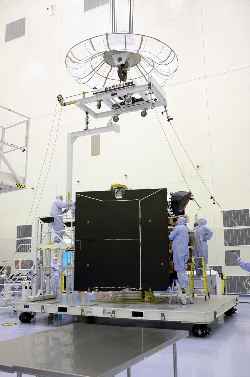
Engineers and technicians work together to install reaction wheels on the underside of the main body of NASA's Europa Clipper spacecraft. The integration of the wheels was one of the latest steps of the spacecraft's assembly, test, and launch operations phase, now underway way in the Spacecraft Assembly Facility at the agency's Jet Propulsion Laboratory in Southern California. Europa Clipper is set to launch to Jupiter's moon Europa in October 2024. When the spacecraft heads through deep space, slips into orbit around Jupiter, and collects science observations while flying dozens of times by Europa, the wheels rotate the orbiter so that its antennas can communicate with Earth and so its science instruments, including cameras, can stay oriented toward Europa. Two feet wide and made of steel, aluminum, and titanium, the wheels spin rapidly to create a force that causes the orbiter to rotate in the opposite direction. The wheels will run on electricity provided by the spacecraft's vast solar arrays. Scientists believe the icy moon Europa harbors a vast internal ocean that may have conditions suitable for supporting life. Europa Clipper will fly by the moon about 50 times while its suite of science instruments gathers data on the moon's atmosphere, surface, and interior – information that will help scientists learn more about the ocean, the ice crust, and potential plumes that may be venting subsurface water into space. https://photojournal.jpl.nasa.gov/catalog/PIA25496
KENNEDY SPACE CENTER, FLA. - In a clean room inside the Payload Hazardous Servicing Facility (PHSF) at NASA's Kennedy Space Center, an overhead crane has moved into position over the Lockheed Martin-built Mars Reconnaissance Orbiter (MRO). The crane will lift the spacecraft and move it to a nearby workstand for final assembly and testing. In the PHSF, the spacecraft will undergo multiple mechanical assembly operations and electrical tests to verify its readiness for launch. A test this month will verify the spacecraft's ability to communicate through NASA's Deep Space Network tracking stations. A June test will check the deployment of the spacecraft's high gain communications antenna. Another major deployment test will check out the spacecraft's large solar arrays. The MRO was built for NASA's Jet Propulsion Laboratory in California. It is the next major step in Mars exploration and scheduled for launch from Cape Canaveral Air Force Station in a window opening Aug. 10. The MRO is an important next step in fulfilling NASA's vision of space exploration and ultimately sending human explorers to Mars and beyond.
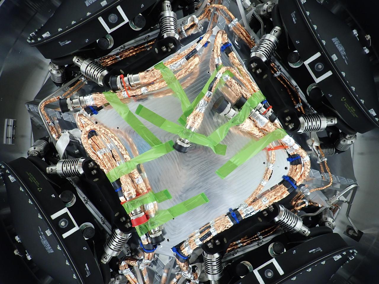
All four of the reaction wheels installed onto NASA's Europa Clipper are visible in this photo, which was shot from underneath the main body of the spacecraft while it is being assembled at the agency's Jet Propulsion Laboratory in Southern California. The spacecraft is set to launch in October 2024 and will head toward Jupiter's moon Europa, where it will collect science observations while flying by the icy moon dozens of times. During its journey through deep space and its flybys of Europa, the spacecraft's reaction wheels rotate the orbiter so its antennas can communicate with Earth and so its science instruments, including cameras, can stay oriented toward Europa. Two feet wide and made of steel, aluminum, and titanium, the wheels spin rapidly to create a force that causes the orbiter to rotate in the opposite direction. The wheels will run on electricity provided by the spacecraft's vast solar arrays. The green tape that is visible here keeps cables temporarily secured during the wheel installation. Scientists believe Europa harbors a vast internal ocean that may have conditions suitable for supporting life. Europa Clipper's suite of science instruments gathers data on the moon's atmosphere, surface, and interior – information that will help scientists learn more about the ocean, the ice crust, and potential plumes that may be venting subsurface water into space. https://photojournal.jpl.nasa.gov/catalog/PIA25495
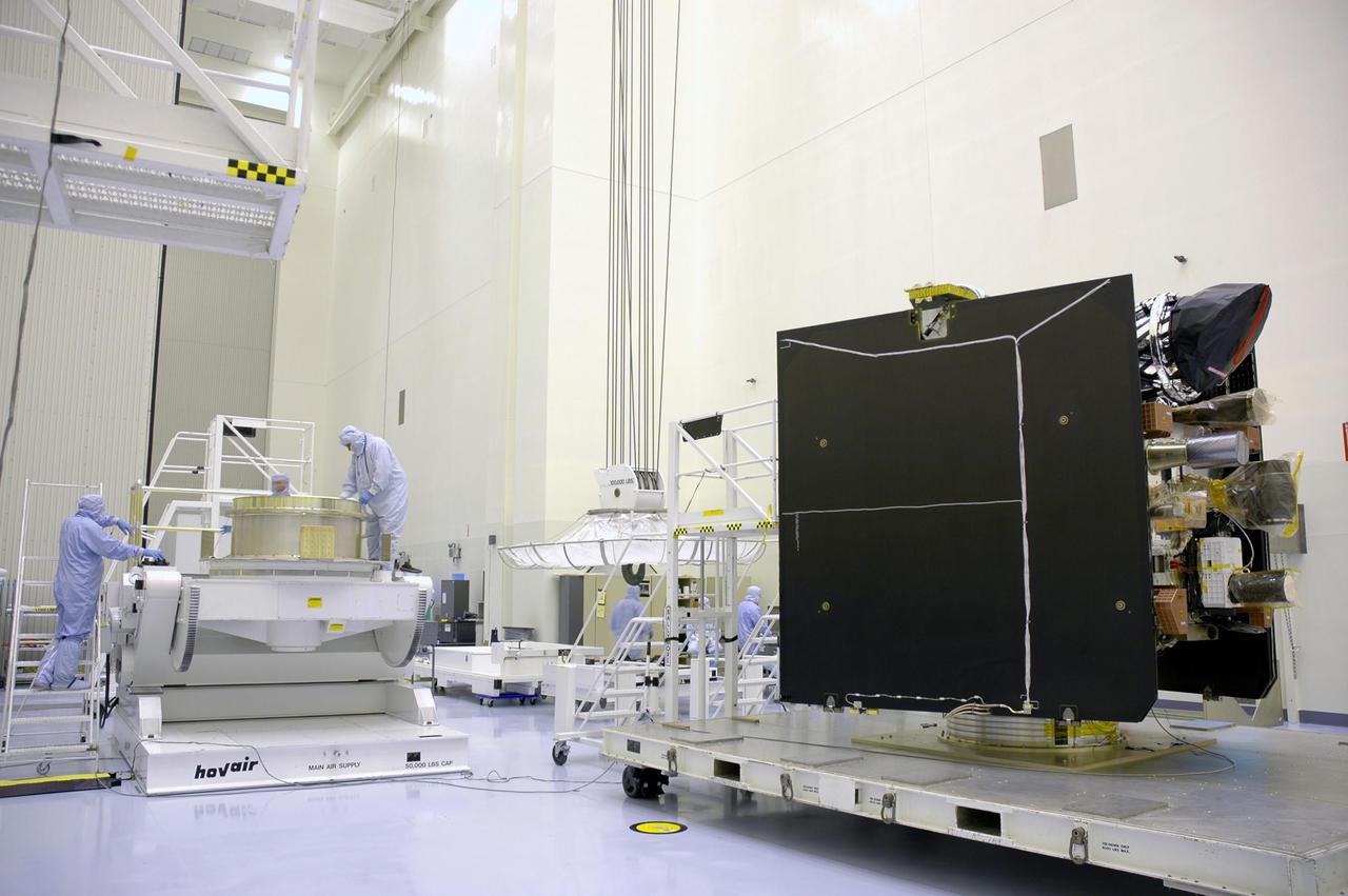
KENNEDY SPACE CENTER, FLA. - In a clean room inside the Payload Hazardous Servicing Facility (PHSF) at NASA's Kennedy Space Center, the Lockheed Martin-built Mars Reconnaissance Orbiter (MRO) is ready to be moved to a nearby workstand for final assembly and testing. In the PHSF, the spacecraft will undergo multiple mechanical assembly operations and electrical tests to verify its readiness for launch. A test this month will verify the spacecraft's ability to communicate through NASA's Deep Space Network tracking stations. A June test will check the deployment of the spacecraft's high gain communications antenna. Another major deployment test will check out the spacecraft's large solar arrays. The MRO was built for NASA's Jet Propulsion Laboratory in California. It is the next major step in Mars exploration and scheduled for launch from Cape Canaveral Air Force Station in a window opening Aug. 10. The MRO is an important next step in fulfilling NASA's vision of space exploration and ultimately sending human explorers to Mars and beyond.

KENNEDY SPACE CENTER, FLA. - In a clean room inside the Payload Hazardous Servicing Facility (PHSF) at NASA's Kennedy Space Center, Lockheed Martin workers begin removing the protective cover from one of the boxes containing NASA's Mars Reconnaissance Orbiter to a clean room. Here in the PHSF, the spacecraft will undergo multiple mechanical assembly operations and electrical tests to verify its readiness for launch. A test this month will verify the spacecraft's ability to communicate through NASA's Deep Space Network tracking stations. A June test will check the deployment of the spacecraft's high gain communications antenna. Another major deployment test will check out the spacecraft's large solar arrays. The MRO was built by Lockheed Martin for NASA's Jet Propulsion Laboratory in California. It is the next major step in Mars exploration and scheduled for launch from Cape Canaveral Air Force Station in a window opening Aug. 10. The MRO is an important next step in fulfilling NASA's vision of space exploration and ultimately sending human explorers to Mars and beyond.
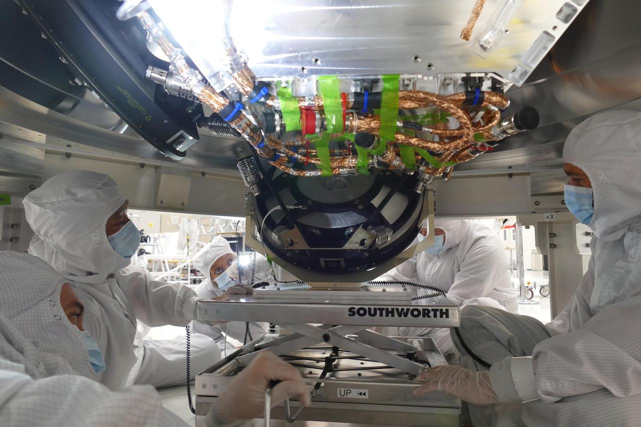
Engineers install a 2-foot-wide reaction wheel onto the main body of NASA's Europa Clipper spacecraft at the agency's Jet Propulsion Laboratory in Southern California. In all, four wheels were integrated onto the spacecraft, which is being assembled for its launch to Jupiter's moon Europa in October 2024. When the spacecraft heads through deep space, slips into orbit around Jupiter, and collects science observations while flying dozens of times by Europa, the wheels rotate the orbiter so that its antennas can communicate with Earth and so its science instruments, including cameras, can stay oriented toward Europa. Two feet wide and made of steel, aluminum, and titanium, the wheels spin rapidly to create a force that causes the orbiter to rotate in the opposite direction. The wheels will run on electricity provided by the spacecraft's vast solar arrays. Scientists believe the icy moon Europa harbors a vast internal ocean that may have conditions suitable for supporting life. Europa Clipper will fly by the moon about 50 times while its suite of science instruments gathers data on the moon's atmosphere, surface, and interior – information that will help scientists learn more about the ocean, the ice crust, and potential plumes that may be venting subsurface water into space. https://photojournal.jpl.nasa.gov/catalog/PIA25497

KENNEDY SPACE CENTER, FLA. - Inside the Payload Hazardous Servicing Facility (PHSF) at NASA's Kennedy Space Center, Lockheed Martin workers move one of the boxes containing NASA's Mars Reconnaissance Orbiter to a clean room. Here in the PHSF, the spacecraft will undergo multiple mechanical assembly operations and electrical tests to verify its readiness for launch. A test this month will verify the spacecraft's ability to communicate through NASA's Deep Space Network tracking stations. A June test will check the deployment of the spacecraft's high gain communications antenna. Another major deployment test will check out the spacecraft's large solar arrays. The MRO was built by Lockheed Martin for NASA's Jet Propulsion Laboratory in California. It is the next major step in Mars exploration and scheduled for launch from Cape Canaveral Air Force Station in a window opening Aug. 10. The MRO is an important next step in fulfilling NASA's vision of space exploration and ultimately sending human explorers to Mars and beyond.
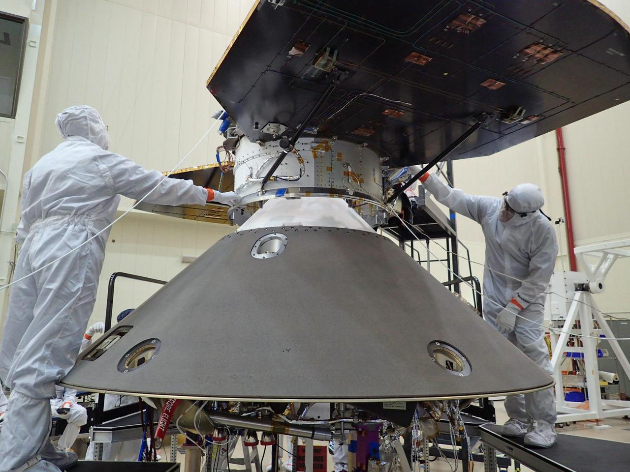
Spacecraft specialists at Lockheed Martin Space Systems, Denver, are preparing to attach the cruise stage of NASA's InSight spacecraft to the top of the spacecraft's back shell in this April 29, 2015, photo. The cruise stage will serve multiple functions during the flight from Earth to Mars. It has its own solar arrays, thrusters and radio antennas. It will be jettisoned shortly before the spacecraft enters the Martian atmosphere. InSight, for Interior Exploration Using Seismic Investigations, Geodesy and Heat Transport, is scheduled for launch in March 2016 and landing in September 2016. It will study the deep interior of Mars to advance understanding of the early history of all rocky planets, including Earth. Note: After thorough examination, NASA managers have decided to suspend the planned March 2016 launch of the Interior Exploration using Seismic Investigations Geodesy and Heat Transport (InSight) mission. The decision follows unsuccessful attempts to repair a leak in a section of the prime instrument in the science payload. http://photojournal.jpl.nasa.gov/catalog/PIA19667
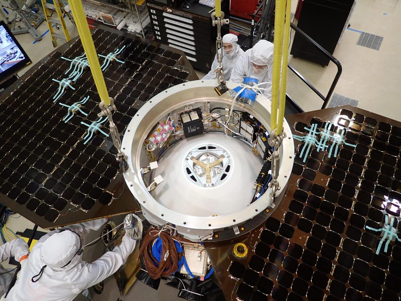
This photo shows the upper side of the cruise stage of NASA's InSight spacecraft as specialists at Lockheed Martin Space Systems, Denver, attach it to the spacecraft's back shell. The photo was taken on April 29, 2015. The cruise stage will serve multiple functions during the flight from Earth to Mars. It has its own solar arrays, thrusters and radio antennas. It will be jettisoned shortly before the spacecraft enters the Martian atmosphere. InSight, for Interior Exploration Using Seismic Investigations, Geodesy and Heat Transport, is scheduled for launch in March 2016 and landing in September 2016. It will study the deep interior of Mars to advance understanding of the early history of all rocky planets, including Earth. Note: After thorough examination, NASA managers have decided to suspend the planned March 2016 launch of the Interior Exploration using Seismic Investigations Geodesy and Heat Transport (InSight) mission. The decision follows unsuccessful attempts to repair a leak in a section of the prime instrument in the science payload. http://photojournal.jpl.nasa.gov/catalog/PIA19668
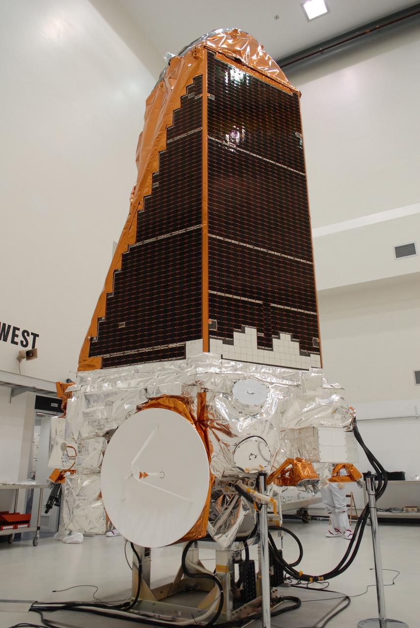
CAPE CANAVERAL, Fla. – NASA's Kepler spacecraft, that will be launched in March aboard a United Launch Alliance Delta II rocket, is ready for the media opportunity Jan. 30. Visible are the solar arrays on top and the high-gain antenna at lower left. The event, being held at the Astrotech Space Operations facility in Titusville, Fla., will provide media representatives an opportunity to photograph the space telescope and to interview project officials from NASA and Ball Aerospace, builder of the spacecraft. Kepler is designed to survey more that 100,000 stars in our galaxy to determine the number of sun-like stars that have Earth-size and larger planets, including those that lie in a star's "habitable zone," a region where liquid water, and perhaps life, could exist. If these Earth-size worlds do exist around stars like our sun, Kepler is expected to be the first to find them and the first to measure how common they are. The liftoff of Kepler aboard a Delta II rocket is currently planned for 10:48 p.m. EST March 5 from Space Launch Complex 17 on Cape Canaveral Air Force Station. Photo credit: NASA/Troy Cryder
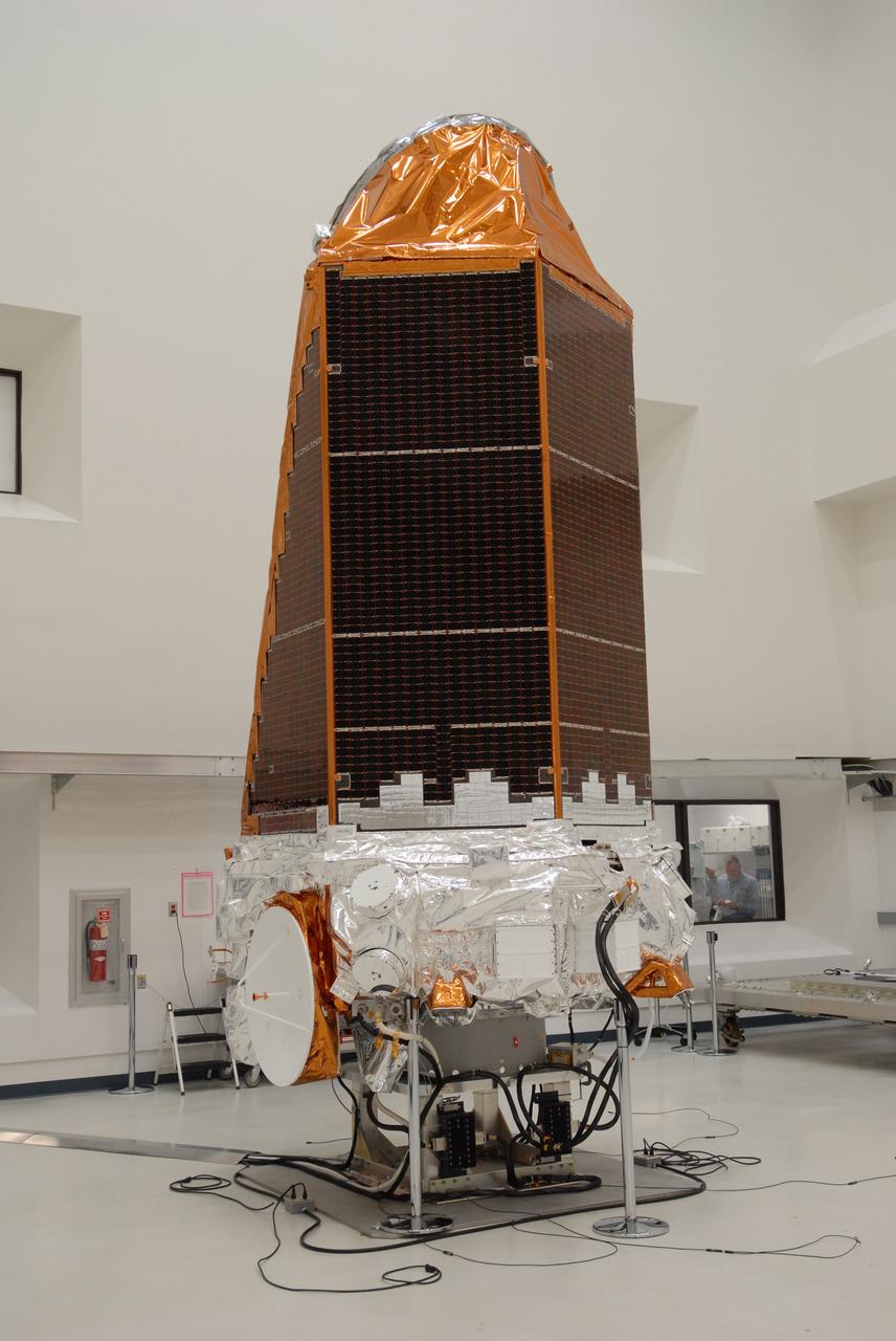
CAPE CANAVERAL, Fla. – NASA's Kepler spacecraft, that will be launched in March aboard a United Launch Alliance Delta II rocket, is ready for the media opportunity Jan. 30. Visible are the solar arrays on top and the high-gain antenna at lower left. The event, being held at the Astrotech Space Operations facility in Titusville, Fla., will provide media representatives an opportunity to photograph the space telescope and to interview project officials from NASA and Ball Aerospace, builder of the spacecraft. Kepler is designed to survey more that 100,000 stars in our galaxy to determine the number of sun-like stars that have Earth-size and larger planets, including those that lie in a star's "habitable zone," a region where liquid water, and perhaps life, could exist. If these Earth-size worlds do exist around stars like our sun, Kepler is expected to be the first to find them and the first to measure how common they are. The liftoff of Kepler aboard a Delta II rocket is currently planned for 10:48 p.m. EST March 5 from Space Launch Complex 17 on Cape Canaveral Air Force Station. Photo credit: NASA/Troy Cryder
![In the Spacecraft Assembly and Encapsulation Facility -2, workers check the movement of the <a href='http:__mars.jpl.nasa.gov_2001_'>2001 Mars Odyssey Orbiter <_a> as it is carried to the workstand at right. The circular object facing forward on the spacecraft is a high-gain antenna. On the right side is the rectangular solar array assembly. The Mars Odyssey Orbiter carries three science instruments: the Thermal Emission Imaging System (THEMIS), the Gamma Ray Spectrometer (GRS), and the Mars Radiation Environment Experiment (MARIE). THEMIS will map the mineralogy and morphology of the Martian surface using a high-resolution camera and a thermal infrared imaging spectrometer. The GRS will achieve global mapping of the elemental composition of the surface and determine the abundance of hydrogen in the shallow subsurface. [The GRS is a rebuild of the instrument lost with the Mars Observer mission.] The MARIE will characterize aspects of the near-space radiation environment as related to the radiation-related risk to human explorers. The Mars Odyssey Orbiter is scheduled for launch on April 7, 2001, aboard a Delta 7925 rocket from Launch Pad 17-A, Cape Canaveral Air Force Station](https://images-assets.nasa.gov/image/01pp0100/01pp0100~medium.jpg)
In the Spacecraft Assembly and Encapsulation Facility -2, workers check the movement of the <a href='http:__mars.jpl.nasa.gov_2001_'>2001 Mars Odyssey Orbiter <_a> as it is carried to the workstand at right. The circular object facing forward on the spacecraft is a high-gain antenna. On the right side is the rectangular solar array assembly. The Mars Odyssey Orbiter carries three science instruments: the Thermal Emission Imaging System (THEMIS), the Gamma Ray Spectrometer (GRS), and the Mars Radiation Environment Experiment (MARIE). THEMIS will map the mineralogy and morphology of the Martian surface using a high-resolution camera and a thermal infrared imaging spectrometer. The GRS will achieve global mapping of the elemental composition of the surface and determine the abundance of hydrogen in the shallow subsurface. [The GRS is a rebuild of the instrument lost with the Mars Observer mission.] The MARIE will characterize aspects of the near-space radiation environment as related to the radiation-related risk to human explorers. The Mars Odyssey Orbiter is scheduled for launch on April 7, 2001, aboard a Delta 7925 rocket from Launch Pad 17-A, Cape Canaveral Air Force Station
![In the Spacecraft Assembly & Encapsulation Facility -2, workers check the movement of the <a href="http://mars.jpl.nasa.gov/2001/">2001 Mars Odyssey Orbiter </a> as it is carried to the workstand at right. The circular object facing forward on the spacecraft is a high-gain antenna. On the right side is the rectangular solar array assembly. The Mars Odyssey Orbiter carries three science instruments: the Thermal Emission Imaging System (THEMIS), the Gamma Ray Spectrometer (GRS), and the Mars Radiation Environment Experiment (MARIE). THEMIS will map the mineralogy and morphology of the Martian surface using a high-resolution camera and a thermal infrared imaging spectrometer. The GRS will achieve global mapping of the elemental composition of the surface and determine the abundance of hydrogen in the shallow subsurface. [The GRS is a rebuild of the instrument lost with the Mars Observer mission.] The MARIE will characterize aspects of the near-space radiation environment as related to the radiation-related risk to human explorers. The Mars Odyssey Orbiter is scheduled for launch on April 7, 2001, aboard a Delta 7925 rocket from Launch Pad 17-A, Cape Canaveral Air Force Station](https://images-assets.nasa.gov/image/KSC01pp0100/KSC01pp0100~medium.jpg)
In the Spacecraft Assembly & Encapsulation Facility -2, workers check the movement of the <a href="http://mars.jpl.nasa.gov/2001/">2001 Mars Odyssey Orbiter </a> as it is carried to the workstand at right. The circular object facing forward on the spacecraft is a high-gain antenna. On the right side is the rectangular solar array assembly. The Mars Odyssey Orbiter carries three science instruments: the Thermal Emission Imaging System (THEMIS), the Gamma Ray Spectrometer (GRS), and the Mars Radiation Environment Experiment (MARIE). THEMIS will map the mineralogy and morphology of the Martian surface using a high-resolution camera and a thermal infrared imaging spectrometer. The GRS will achieve global mapping of the elemental composition of the surface and determine the abundance of hydrogen in the shallow subsurface. [The GRS is a rebuild of the instrument lost with the Mars Observer mission.] The MARIE will characterize aspects of the near-space radiation environment as related to the radiation-related risk to human explorers. The Mars Odyssey Orbiter is scheduled for launch on April 7, 2001, aboard a Delta 7925 rocket from Launch Pad 17-A, Cape Canaveral Air Force Station
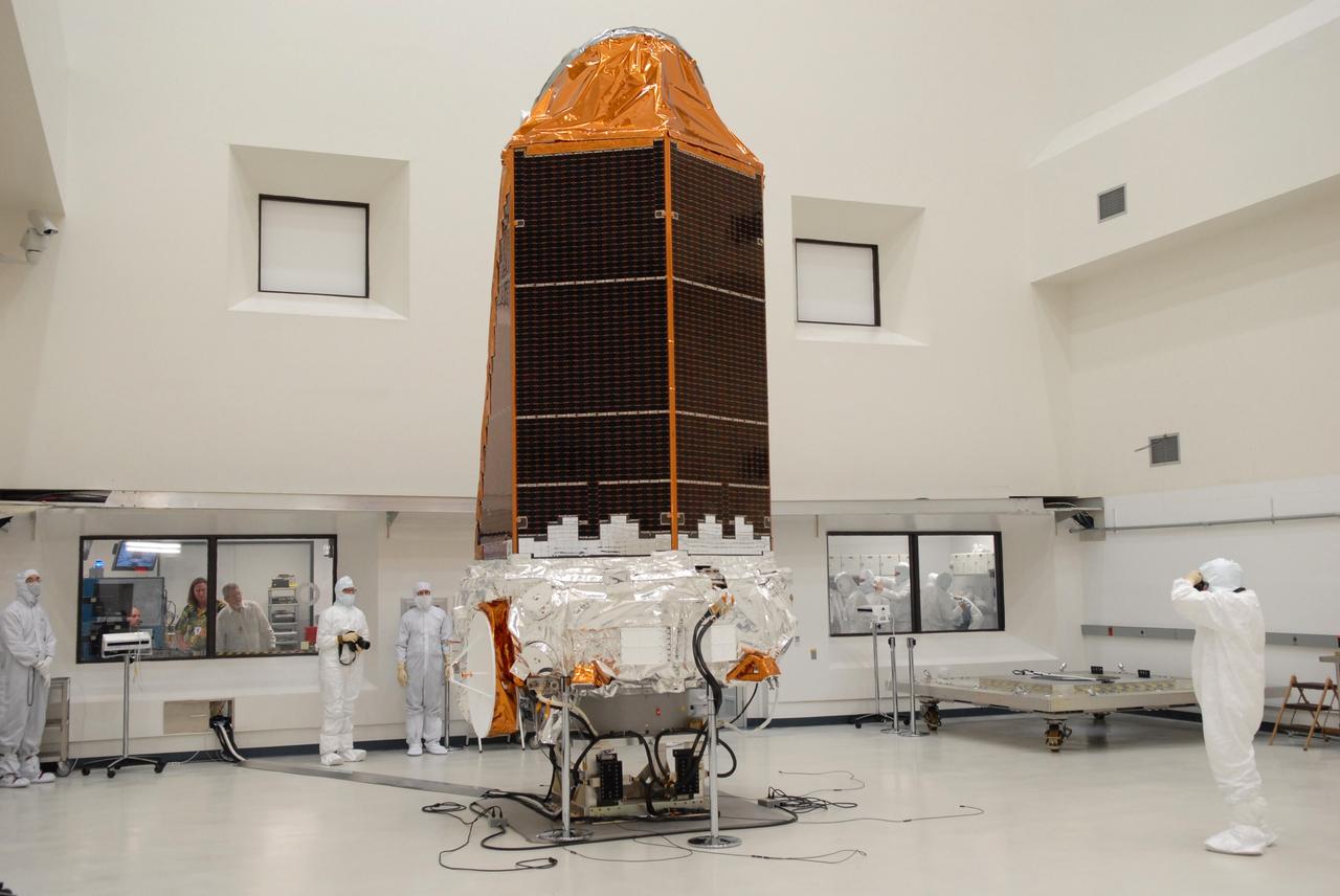
CAPE CANAVERAL, Fla. – NASA's Kepler spacecraft, that will be launched in March aboard a United Launch Alliance Delta II rocket, is photographed by journalists dressed in clean-room suits. Visible are the solar arrays on top and the high-gain antenna at lower left. The event, being held at the Astrotech Space Operations facility in Titusville, Fla., provides media representatives an opportunity to photograph the space telescope and to interview project officials from NASA and Ball Aerospace, builder of the spacecraft. Kepler is designed to survey more that 100,000 stars in our galaxy to determine the number of sun-like stars that have Earth-size and larger planets, including those that lie in a star's "habitable zone," a region where liquid water, and perhaps life, could exist. If these Earth-size worlds do exist around stars like our sun, Kepler is expected to be the first to find them and the first to measure how common they are. The liftoff of Kepler aboard a Delta II rocket is currently planned for 10:48 p.m. EST March 5 from Space Launch Complex 17 on Cape Canaveral Air Force Station. Photo credit: NASA/Troy Cryder