
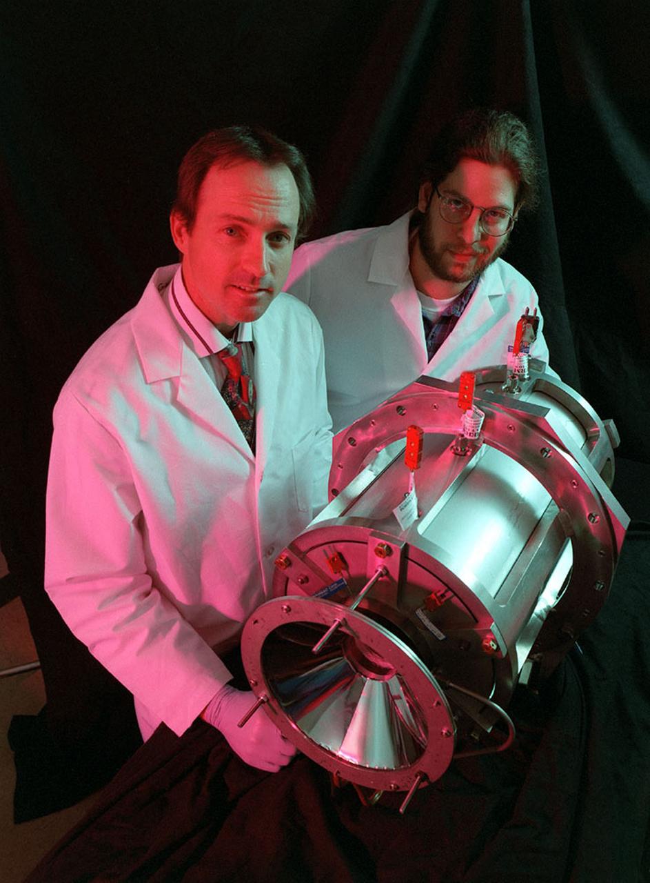
Researchers at the Marshall Space Flight Center (MSFC) have designed, fabricated, and tested the first solar thermal engine, a non-chemical rocket engine that produces lower thrust but has better thrust efficiency than a chemical combustion engine. This photograph shows components for the thermal propulsion engine being laid out prior to assembly. MSFC turned to solar thermal propulsion in the early 1990s due to its simplicity, safety, low cost, and commonality with other propulsion systems. As part of MSFC's Space Transportation Directorate, the Propulsion Research Center serves as a national resource for research of advanced, revolutionary propulsion technologies. The mission is to move the Nation's capabilities beyond the confines of conventional chemical propulsion into an era of aircraft-like access to Earth-orbit, rapid travel throughout the solar system, and exploration of interstellar space.
PA084 SOLAR THERMAL PROPULSION, BLDG 4590, STROFIO THERMAL BALANCE TEST, CLOSE UP VIEW OF TEST CHAMBERVIEW
PA084 SOLAR THERMAL PROPULSION BLDG 4590. STROFIO THERMAL BALANCE TEST, OVERALL VIEW OF TEST CHAMBER
PA084 SOLAR THERMAL PROPULSION BLDG 4590. STROFIO THERMAL BALANCE TEST, CLOSE UP VIEW OF CHAMBER
PA084 SOLAR THERMAL PROPULSION BLDG 4590 STROFIO THERMAL BALANCE TEST. OVERALL VIEW
PA084 SOLAR THERMAL PROPULSION, BLDG 4590, STROFIO THERMAL BALANCE TEST, OVERALL VIEW
PA084 SOLAR THERMAL PROPULSION BLDG 4590, STROFIO THERMAL BALANCE TEST, OVERALL VIEW
PA084 SOLAR THERMAL PROPULSION. BLDG 4590 STROFIO THERMAL BALANCE TEST, MIRROR VIEW
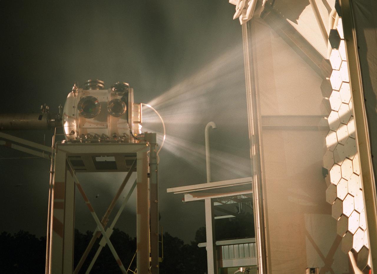
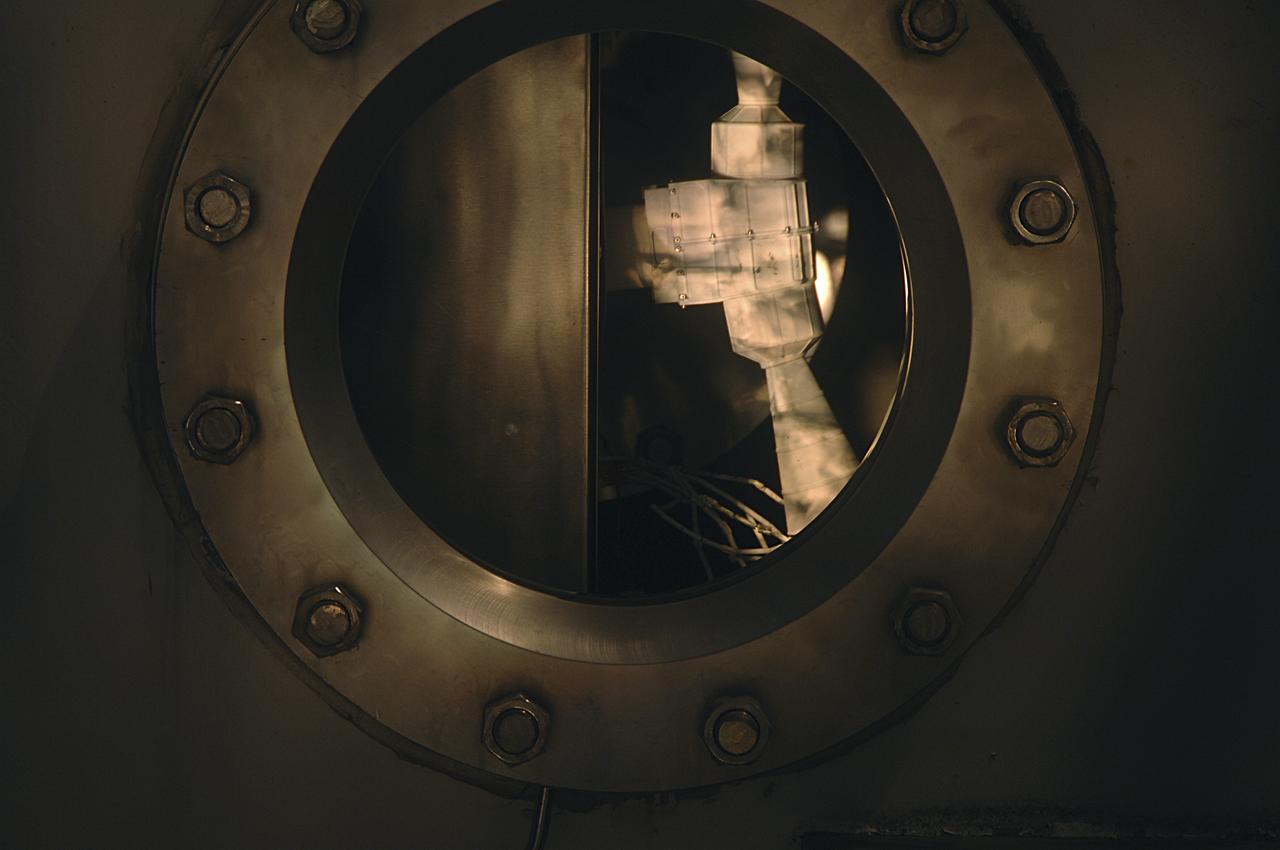
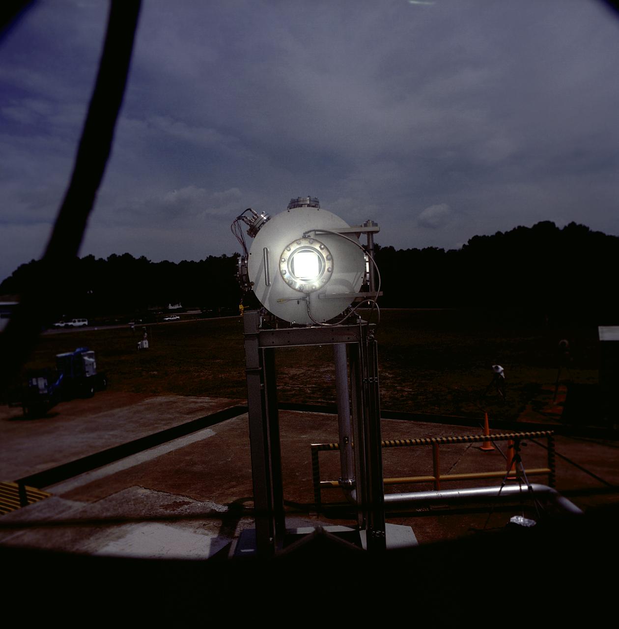
Researchers at the Marshall Space Flight Center (MSFC) have designed, fabricated, and tested the first solar thermal engine, a non-chemical rocket engine that produces lower thrust but has better thrust efficiency than a chemical combustion engine. MSFC turned to solar thermal propulsion in the early 1990s due to its simplicity, safety, low cost, and commonality with other propulsion systems. Solar thermal propulsion works by acquiring and redirecting solar energy to heat a propellant. The 20- by 24-ft heliostat mirror (not shown in this photograph) has a dual-axis control that keeps a reflection of the sunlight on the 18-ft diameter concentrator mirror, which then focuses the sunlight to a 4-in focal point inside the vacuum chamber. The focal point has 10 kilowatts of intense solar power. This image, taken during the test, depicts the light being concentrated into the focal point inside the vacuum chamber. As part of MSFC's Space Transportation Directorate, the Propulsion Research Center serves as a national resource for research of advanced, revolutionary propulsion technologies. The mission is to move the Nation's capabilities beyond the confines of conventional chemical propulsion into an era of aircraft-like access to Earth orbit, rapid travel throughout the solar system, and exploration of interstellar space.
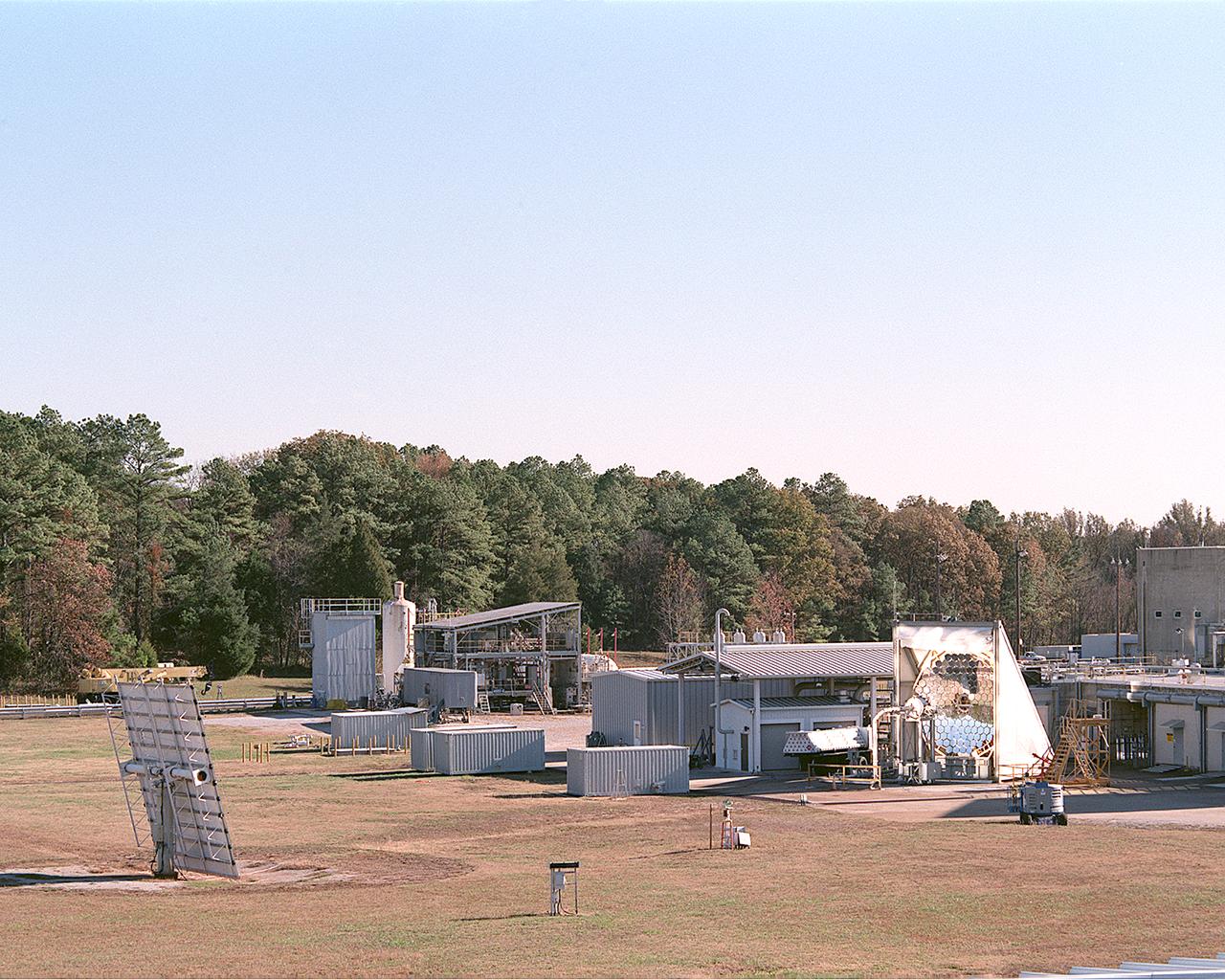
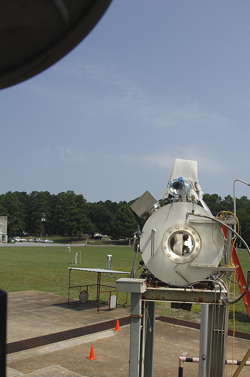
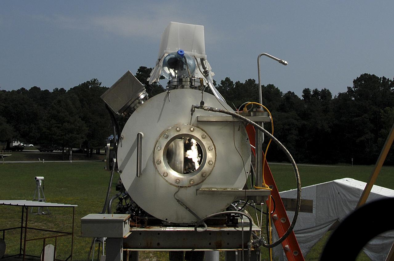
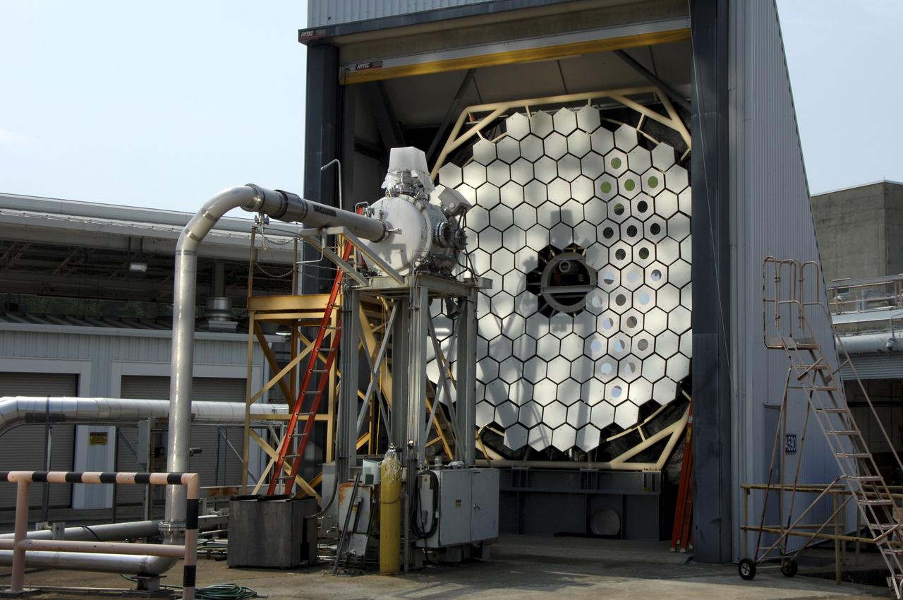
This photograph shows an overall view of the Solar Thermal Propulsion Test Facility at the Marshall Space Flight Center (MSFC). The 20-by 24-ft heliostat mirror, shown at the left, has dual-axis control that keeps a reflection of the sunlight on an 18-ft diameter concentrator mirror (right). The concentrator mirror then focuses the sunlight to a 4-in focal point inside the vacuum chamber, shown at the front of concentrator mirror. Researchers at MSFC have designed, fabricated, and tested the first solar thermal engine, a non-chemical rocket engine that produces lower thrust but has better thrust efficiency than chemical a combustion engine. MSFC turned to solar thermal propulsion in the early 1990s due to its simplicity, safety, low cost, and commonality with other propulsion systems. Solar thermal propulsion works by acquiring and redirecting solar energy to heat a propell nt. As part of MSFC's Space Transportation Directorate, the Propulsion Research Center serves as a national resource for research of advanced, revolutionary propulsion technologies. The mission is to move the Nation's capabilities beyond the confines of conventional chemical propulsion into an era of aircraft-like access to Earth-orbit, rapid travel throughout the solar system, and exploration of interstellar space.
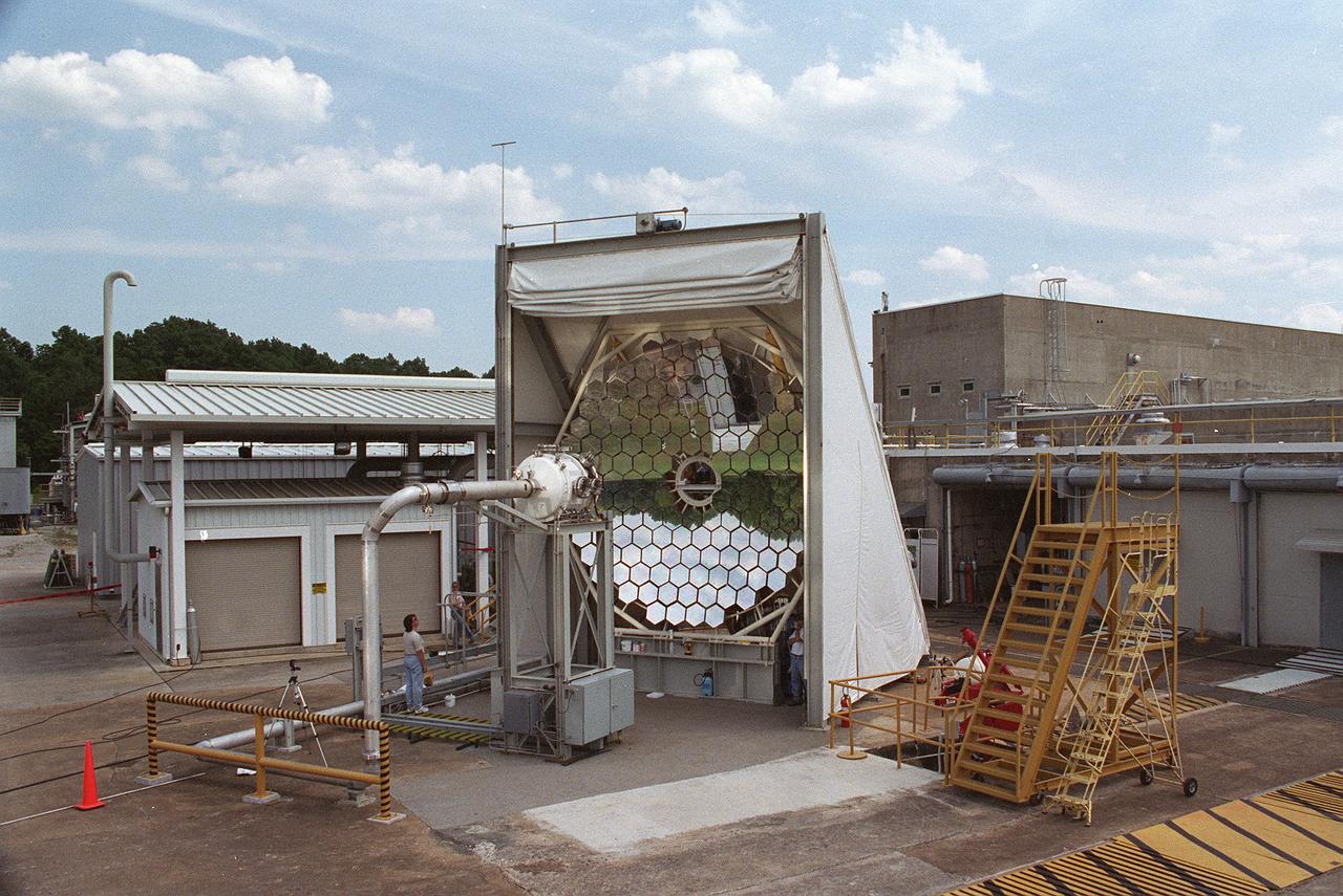
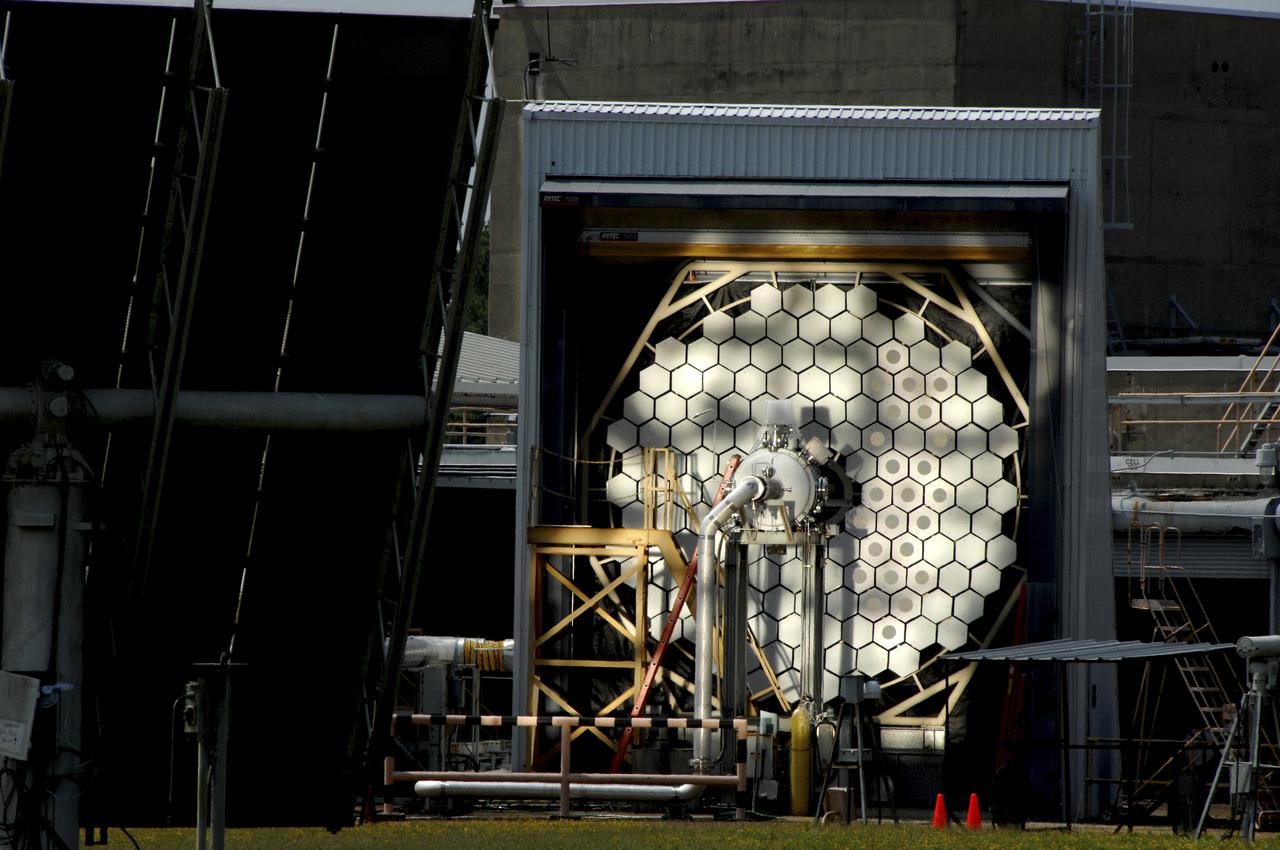
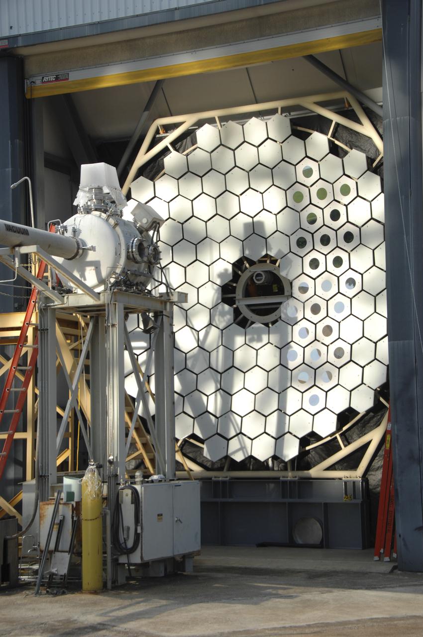
Researchers at the Marshall Space Flight Center (MSFC) have designed, fabricated and tested the first solar thermal engine, a non-chemical rocket engine that produces lower thrust but has better thrust efficiency than a chemical combustion engine. MSFC turned to solar thermal propulsion in the early 1990s due to its simplicity, safety, low cost, and commonality with other propulsion systems. Solar thermal propulsion works by acquiring and redirecting solar energy to heat a propellant. This photograph, taken at MSFC's Solar Thermal Propulsion Test Facility, shows a concentrator mirror, a combination of 144 mirrors forming this 18-ft diameter concentrator, and a vacuum chamber that houses the focal point. The 20- by 24-ft heliostat mirror (not shown in this photograph) has a dual-axis control that keeps a reflection of the sunlight on the 18-foot diameter concentrator mirror, which then focuses the sunlight to a 4-in focal point inside the vacuum chamber. The focal point has 10 kilowatts of intense solar power. As part of MSFC's Space Transportation Directorate, the Propulsion Research Center serves as a national resource for research of advanced, revolutionary propulsion technologies. The mission is to move the Nation's capabilities beyond the confines of conventional chemical propulsion into an era of aircraft-like access to Earth-orbit, rapid travel throughout the solar system, and exploration of interstellar space.
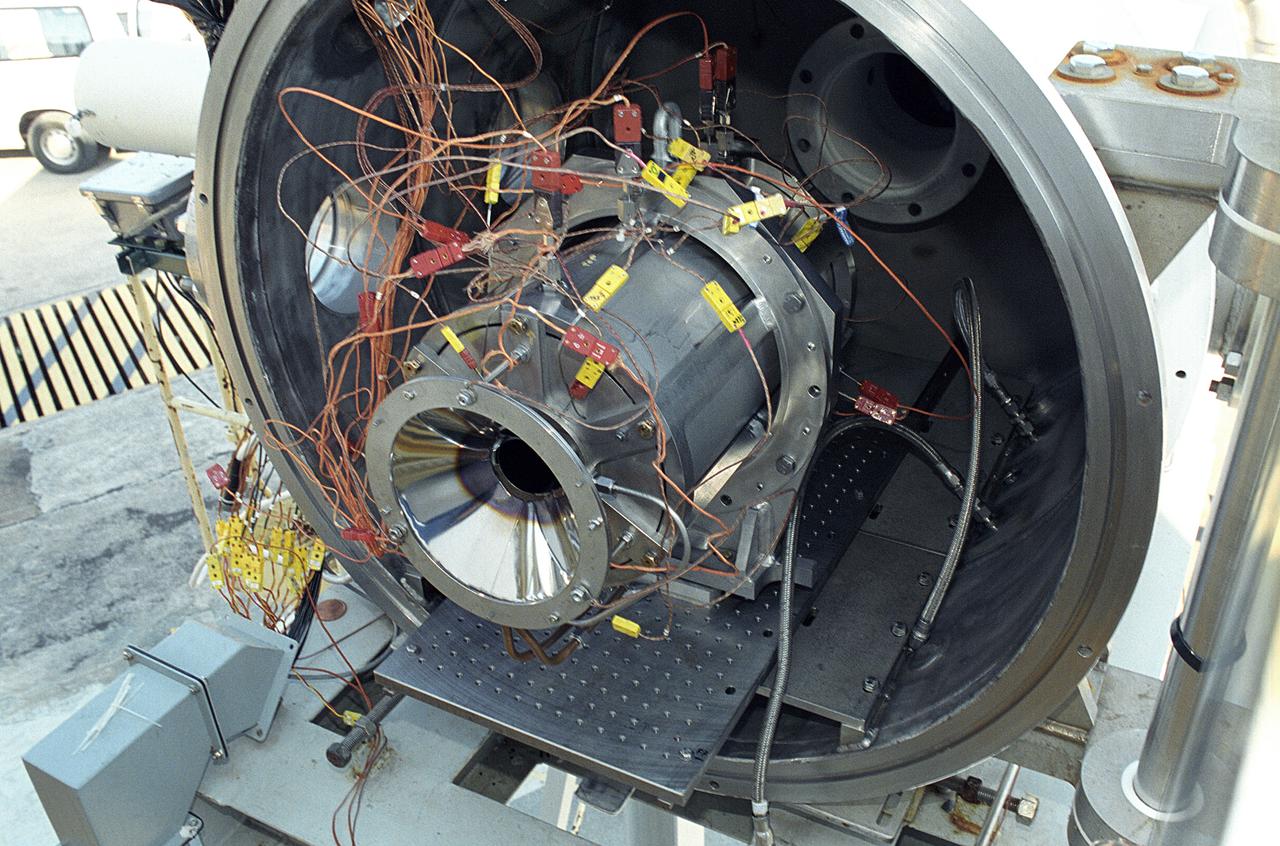
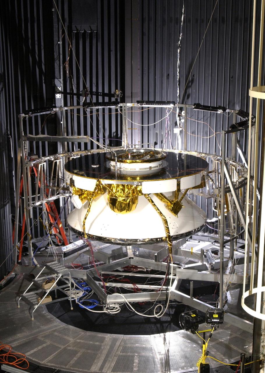
Researchers at the Marshall Space Flight Center (MSFC) have designed, fabricated, and tested the first solar thermal engine, a non-chemical rocket engine that produces lower thrust but has better thrust efficiency than a chemical combustion engine. MSFC turned to solar thermal propulsion in the early 1990s due to its simplicity, safety, low cost, and commonality with other propulsion systems. Solar thermal propulsion works by acquiring and redirecting solar energy to heat a propellant. This photograph shows a fully assembled solar thermal engine placed inside the vacuum chamber at the test facility prior to testing. The 20- by 24-ft heliostat mirror (not shown in this photograph) has a dual-axis control that keeps a reflection of the sunlight on the 18-ft diameter concentrator mirror, which then focuses the sunlight to a 4-in focal point inside the vacuum chamber. The focal point has 10 kilowatts of intense solar power. As part of MSFC's Space Transportation Directorate, the Propulsion Research Center serves as a national resource for research of advanced, revolutionary propulsion technologies. The mission is to move theNation's capabilities beyond the confines of conventional chemical propulsion into an era of aircraft-like access to Earth orbit, rapid travel throughout the solar system, and exploration of interstellar space.
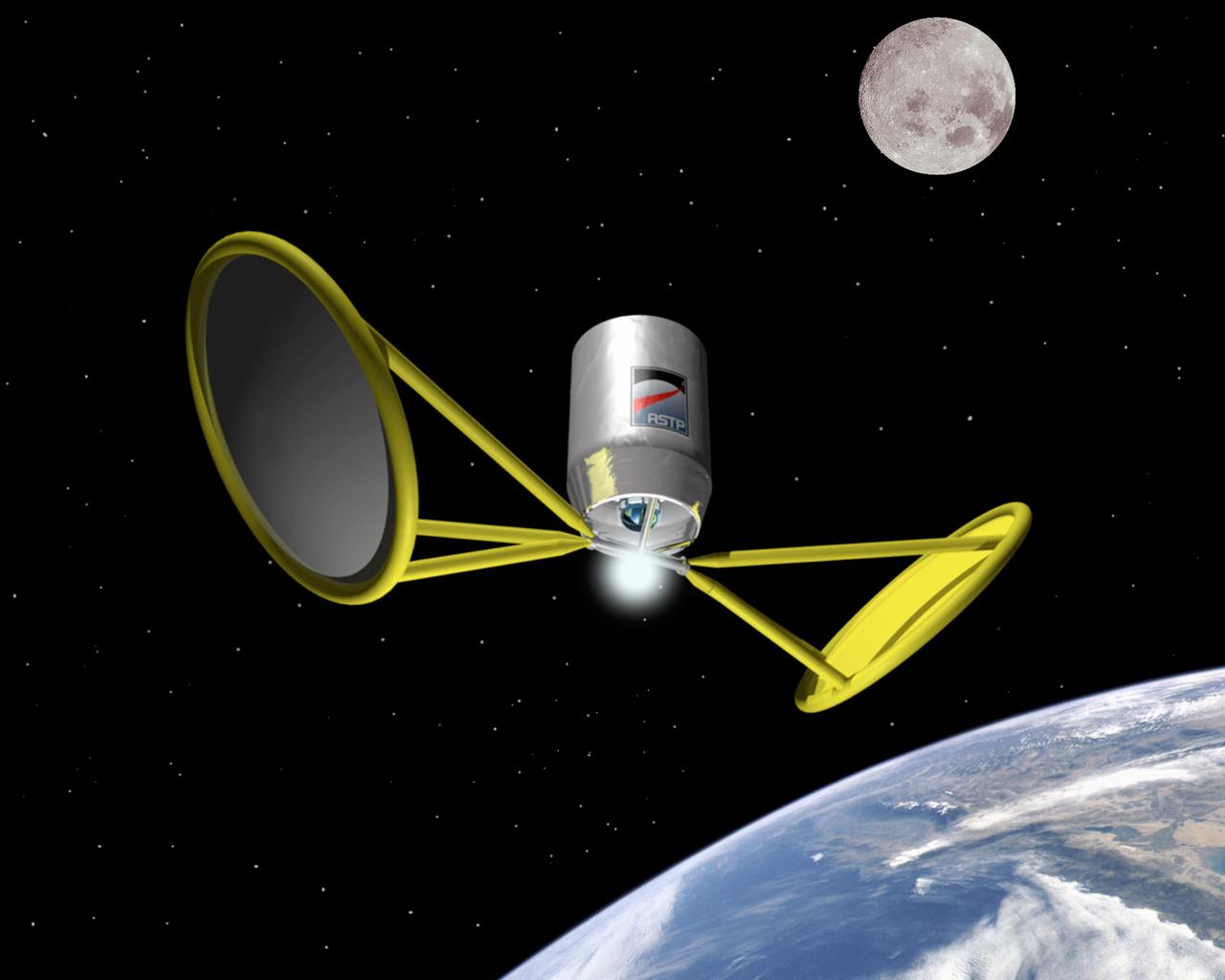
Harnessing the Sun's energy through Solar Thermal Propulsion will propel vehicles through space by significantly reducing weight, complexity, and cost while boosting performance over current conventional upper stages. Another solar powered system, solar electric propulsion, demonstrates ion propulsion is suitable for long duration missions. Pictured is an artist's concept of space flight using solar thermal propulsion.
Researchers at the Marshall Space Flight Center (MSFC) have designed, fabricated, and tested the first solar thermal engine, a non-chemical rocket engine that produces lower thrust but has better thrust efficiency than a chemical combustion engine. MSFC turned to solar thermal propulsion in the early 1990s due to its simplicity, safety, low cost, and commonality with other propulsion systems. Solar thermal propulsion works by acquiring and redirecting solar energy to heat a propellant. The 20- by 24-ft heliostat mirror (not shown in this photograph) has dual-axis control that keeps a reflection of the sunlight on an 18-ft diameter concentrator mirror, which then focuses the sunlight to a 4-in focal point inside the vacuum chamber. The focal point has 10 kilowatts of intense solar power. This photograph is a close-up view of a 4-in focal point inside the vacuum chamber at the MSFC Solar Thermal Propulsion Test facility. As part of MSFC's Space Transportation Directorate, the Propulsion Research Center serves as a national resource for research of advanced, revolutionary propulsion technologies. The mission is to move the Nation's capabilities beyond the confines of conventional chemical propulsion into an era of aircraft-like access to Earth orbit, rapid travel throughout the solar system, and exploration of interstellar space.
NASA Rover 1 in the cruise configuration in Jet Propulsion Laboratory 25-ft Solar Thermal Vacuum Chamber where it underwent environmental testing.
The Direct Gain Solar Thermal Engine was designed with no moving parts. The concept of Solar Thermal Propulsion Research uses focused solar energy from an inflatable concentrator (a giant magnifying glass) to heat a propellant (hydrogen) and allows thermal expansion through the nozzle for low thrust without chemical combustion. Energy limitations and propellant weight associated with traditional combustion engines are non-existant with this concept. The Direct Gain Solar Thermal Engine would be used for moving from a lower orbit to an upper synchronous orbit.
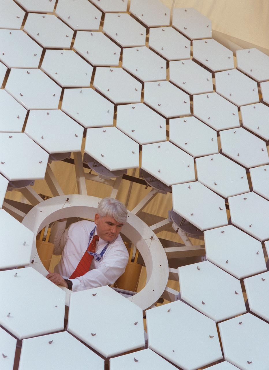
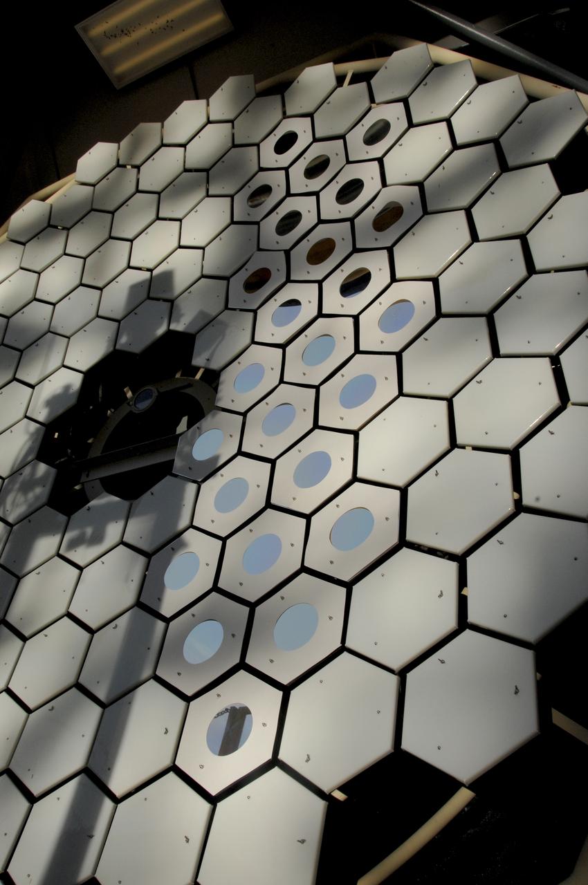
A team of engineers at Marshall Space Flight Center (MSFC) has designed, fabricated, and tested the first solar thermal engine, a non-chemical rocket that produces lower thrust but has better thrust efficiency than the chemical combustion engines. This segmented array of mirrors is the solar concentrator test stand at MSFC for firing the thermal propulsion engines. The 144 mirrors are combined to form an 18-foot diameter array concentrator. The mirror segments are aluminum hexagons that have the reflective surface cut into it by a diamond turning machine, which is developed by MSFC Space Optics Manufacturing Technology Center.
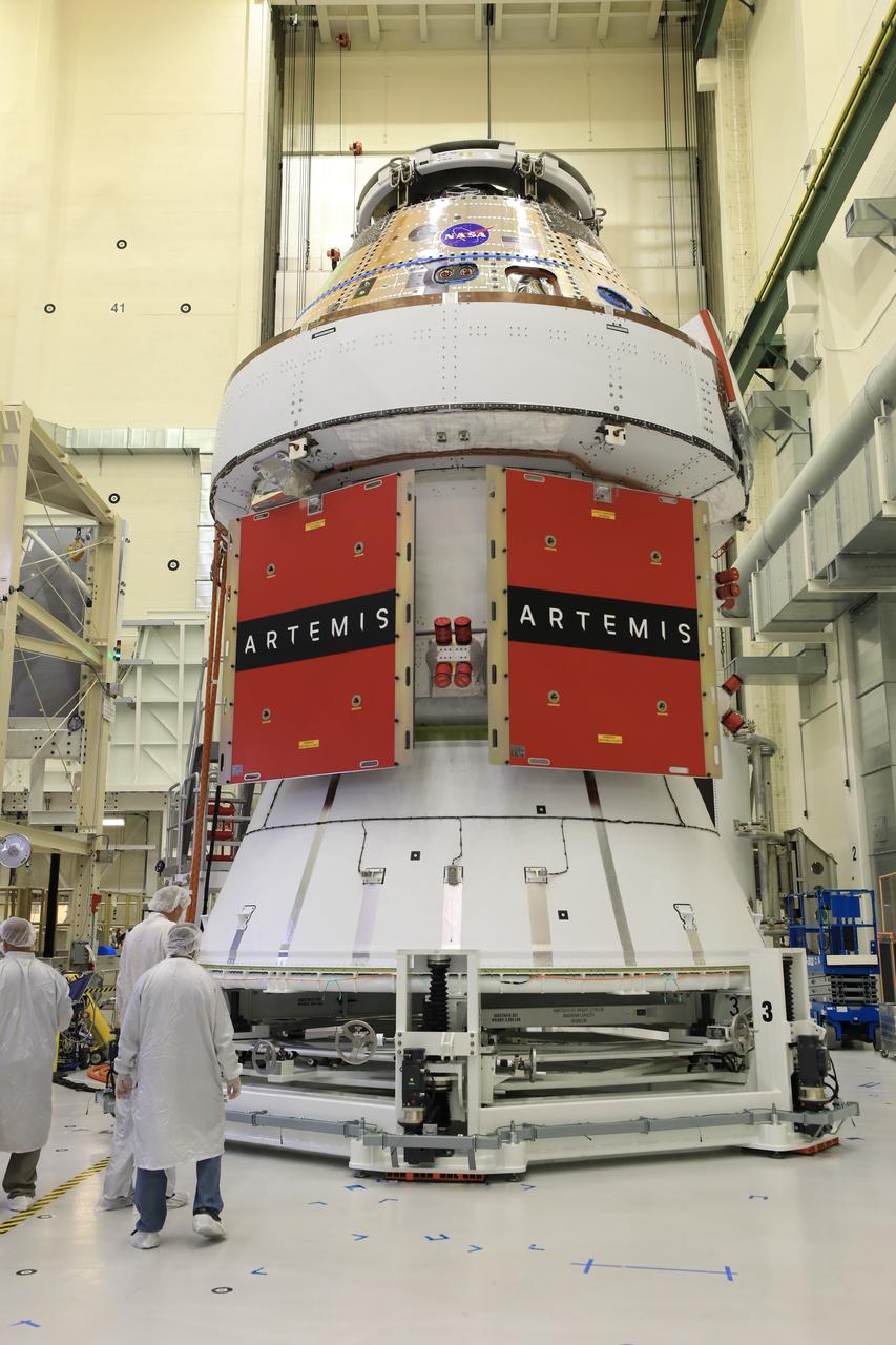
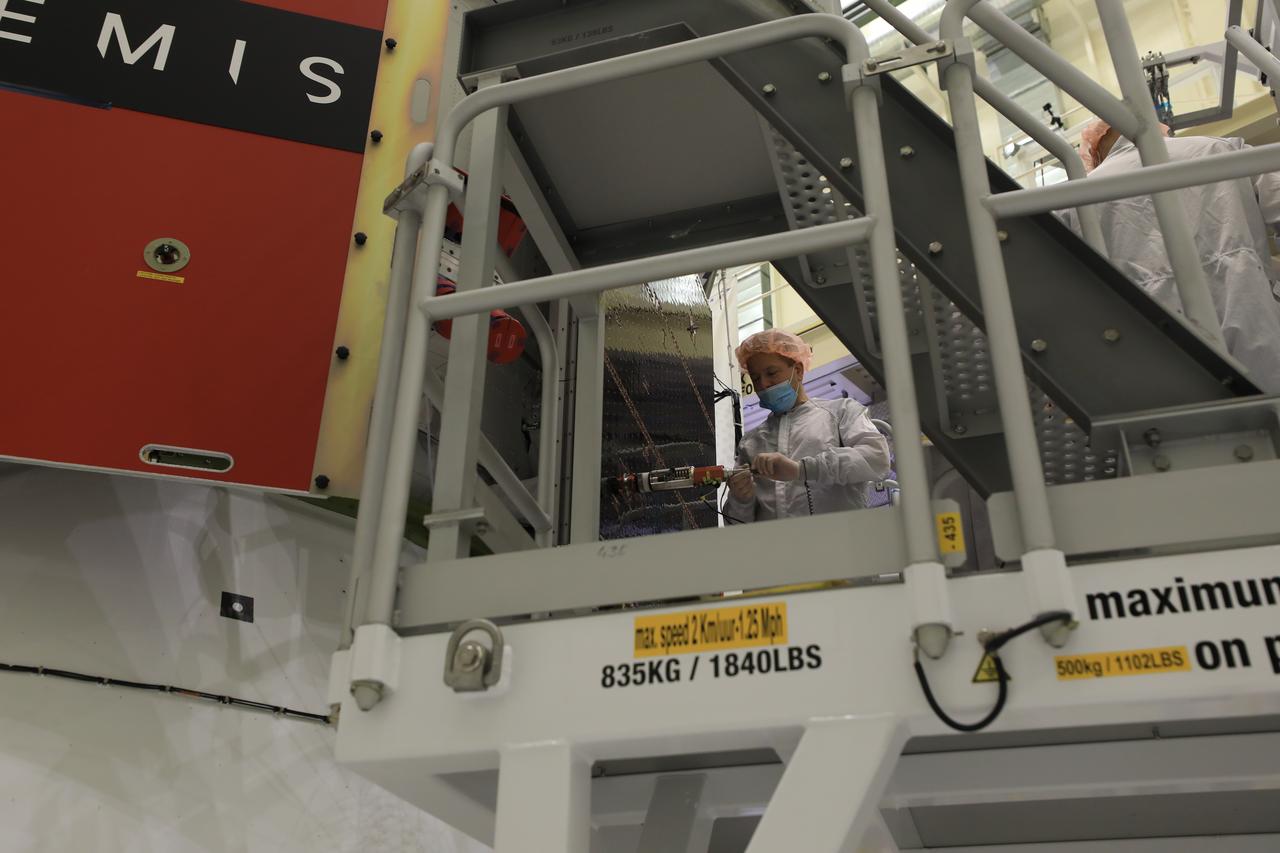
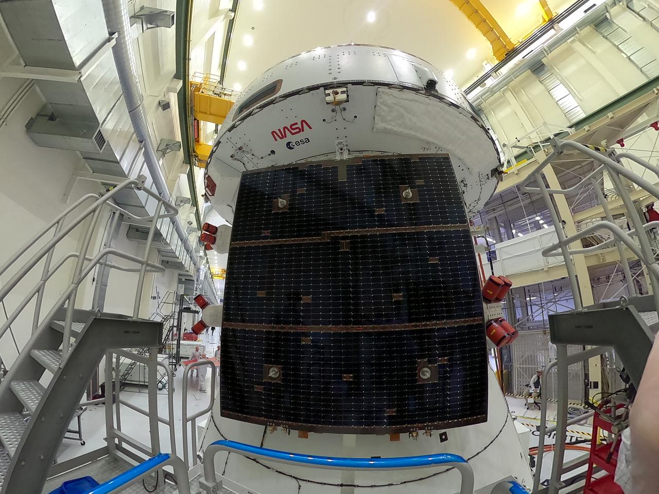
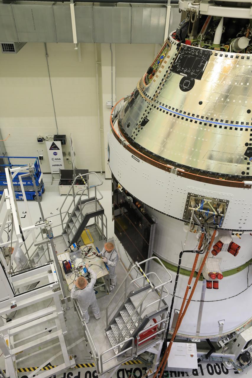
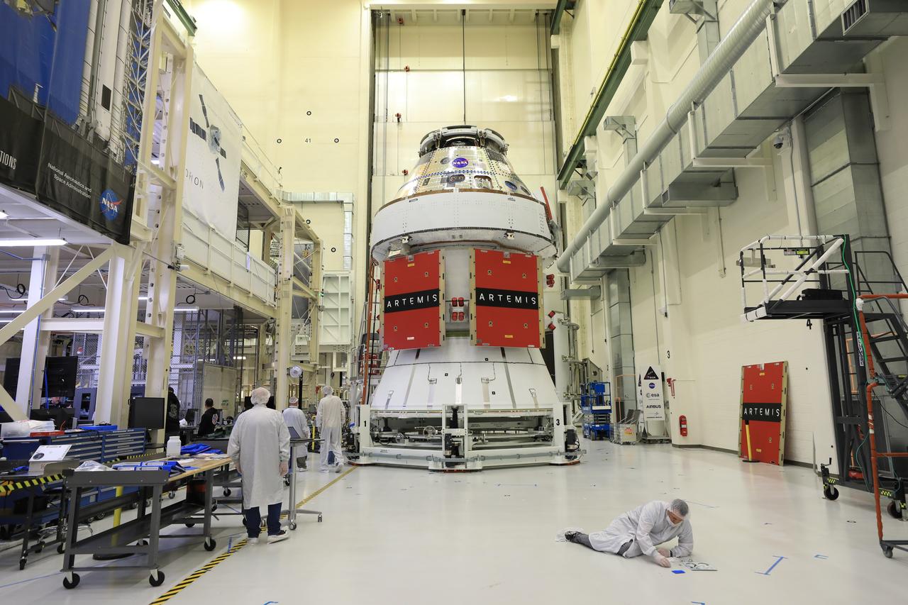
Technicians install four solar array wings on NASA’s Artemis II Orion spacecraft inside the Neil A. Armstrong Operations and Checkout Building at NASA’s Kennedy Space Center in Florida on Monday, March 3, 2025. Each solar array is nearly 23 feet long and can turn on two axes to remain aligned with the Sun for maximum power. Orion’s solar arrays, manufactured and installed by ESA (European Space Agency) and its contractor Airbus, will deliver power to the service module that provides propulsion, thermal control, and electrical power to the spacecraft, as well as air and water for the crew.
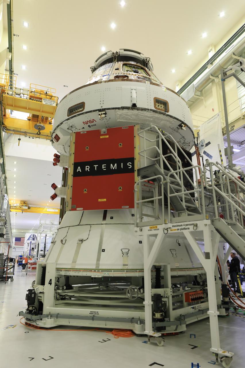
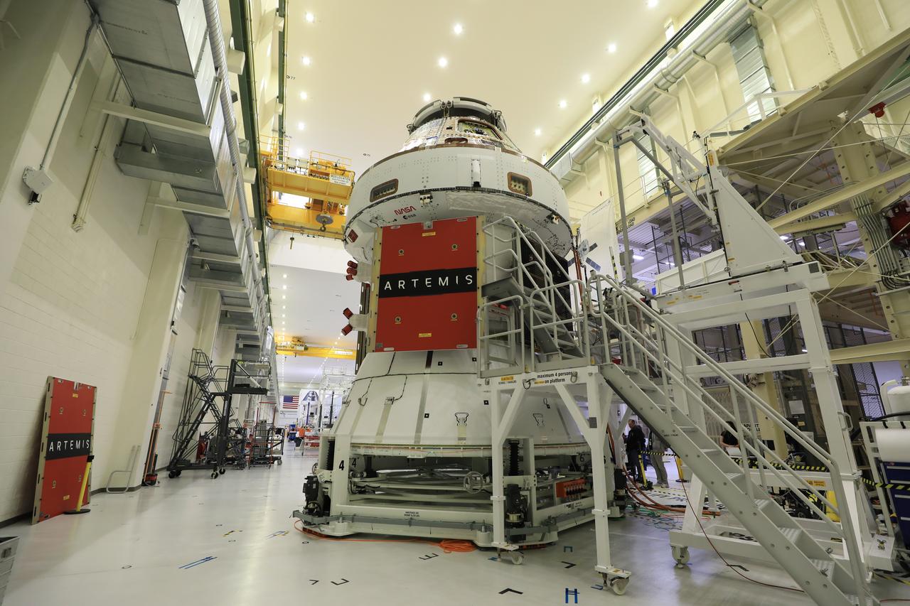
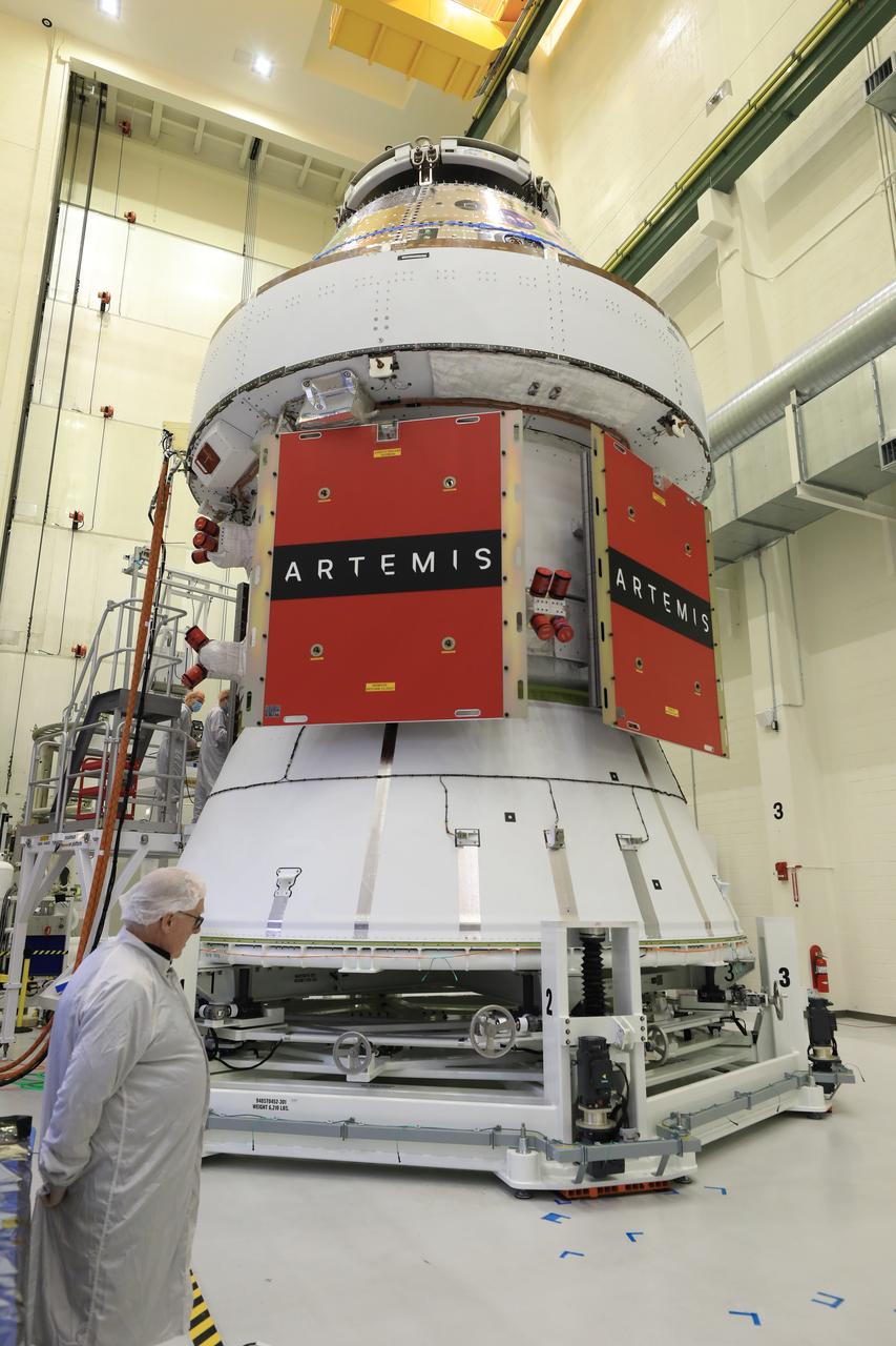
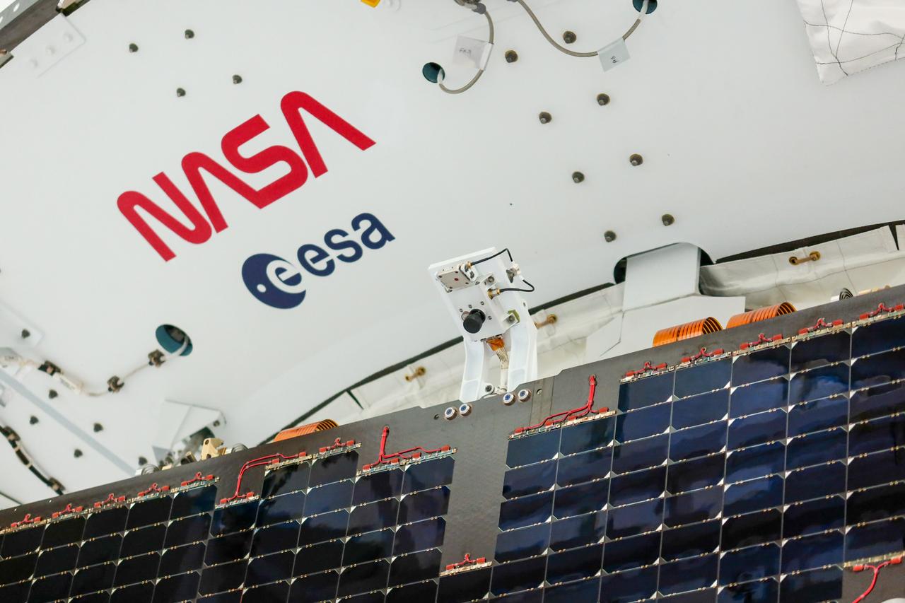
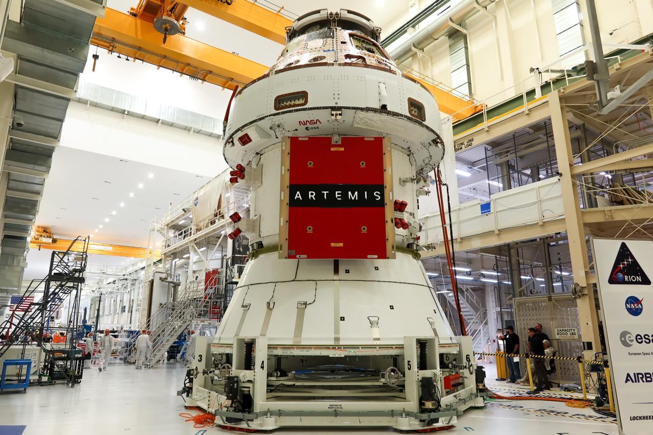
Technicians install four solar array wings on NASA’s Artemis II Orion spacecraft inside the Neil A. Armstrong Operations and Checkout Building at NASA’s Kennedy Space Center in Florida on Monday, March 3, 2025. Each solar array is nearly 23 feet long and can turn on two axes to remain aligned with the Sun for maximum power. Orion’s solar arrays, manufactured and installed by ESA (European Space Agency) and its contractor Airbus, will deliver power to the service module that provides propulsion, thermal control, and electrical power to the spacecraft, as well as air and water for the crew.
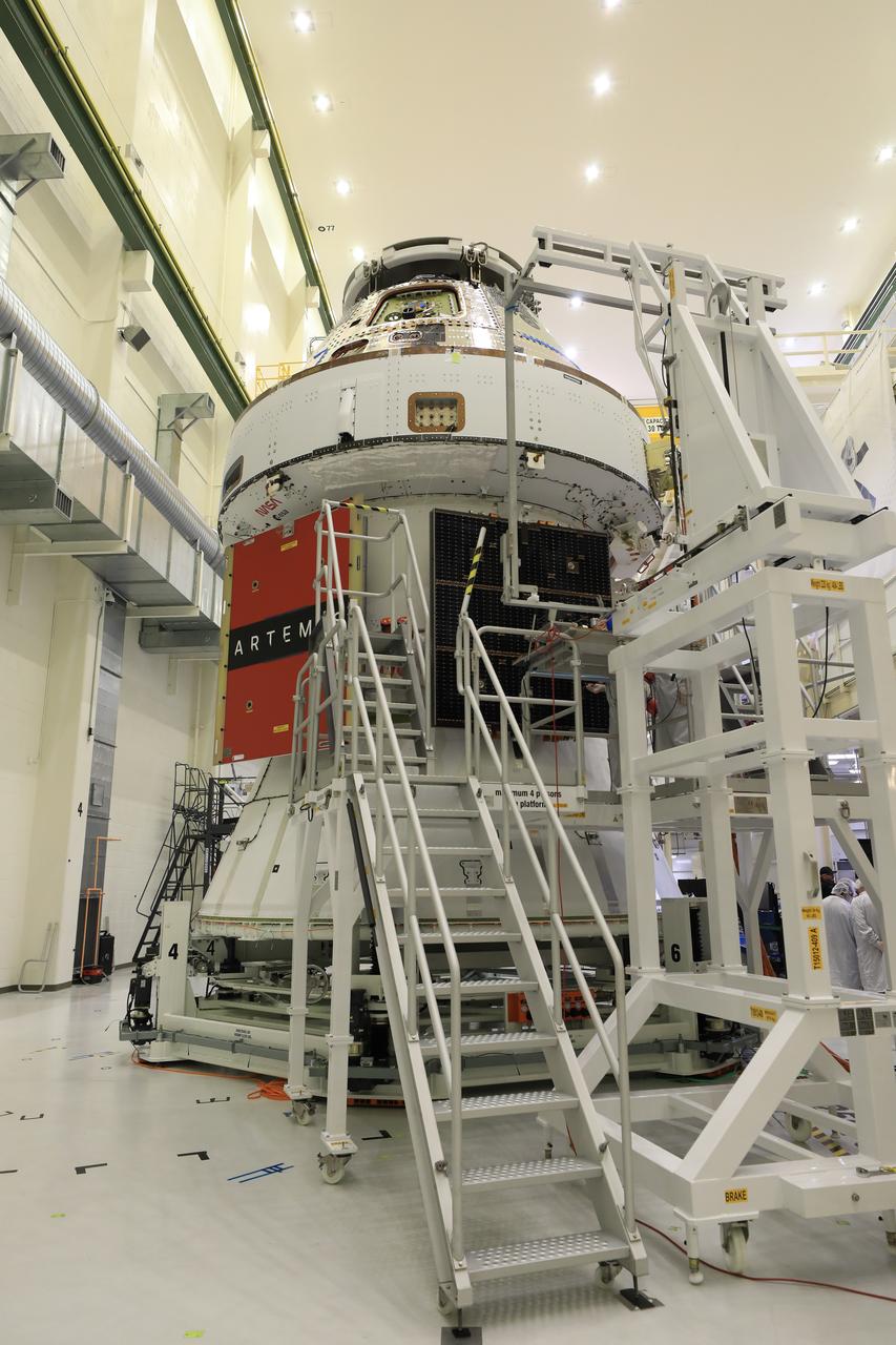
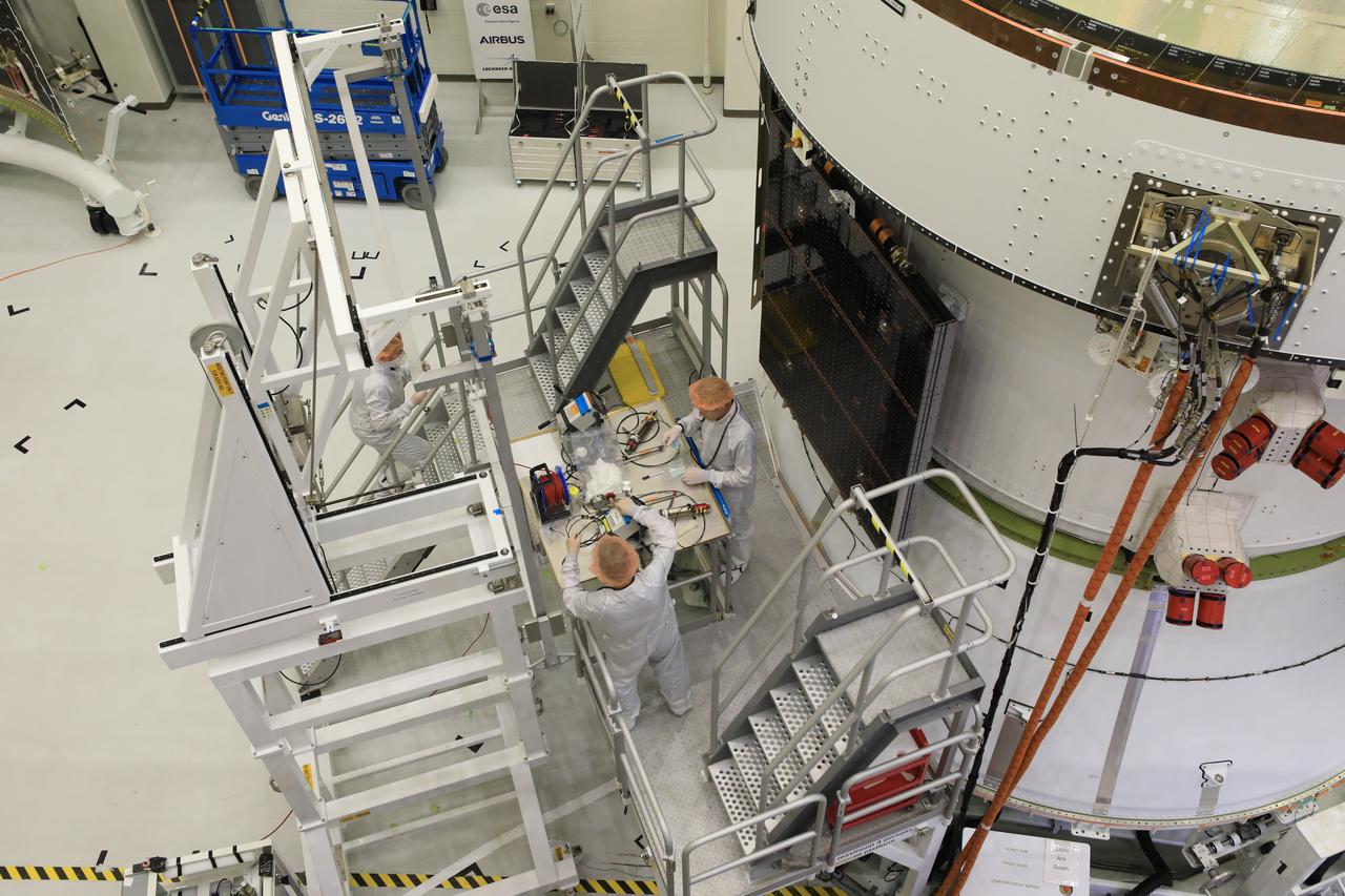
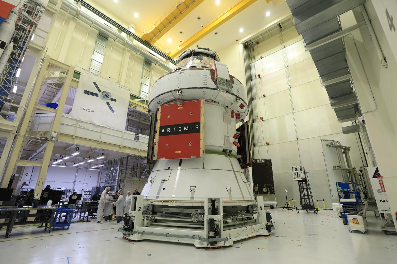
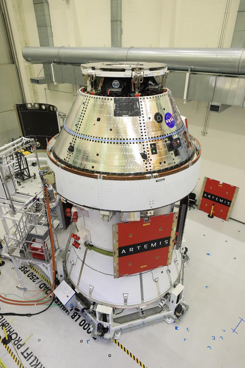
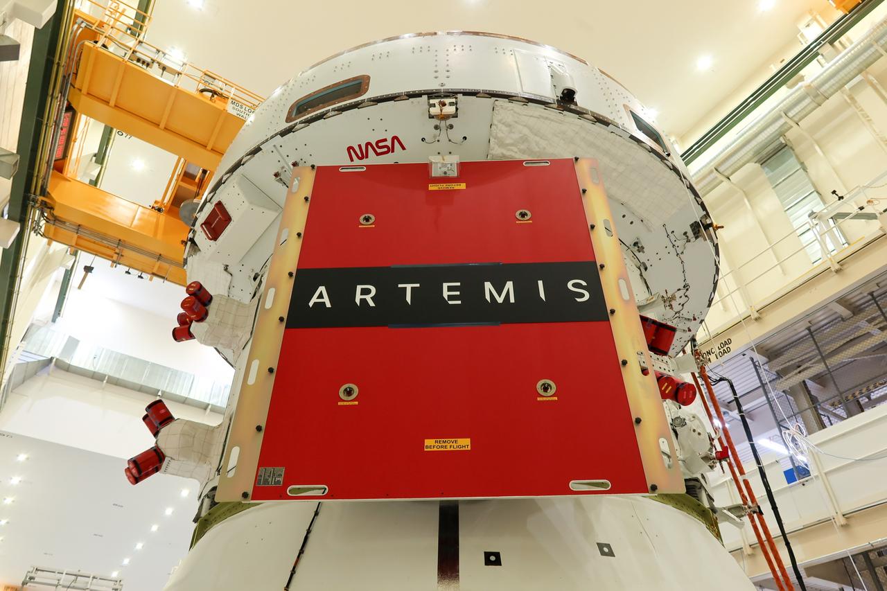
Technicians install four solar array wings on NASA’s Artemis II Orion spacecraft inside the Neil A. Armstrong Operations and Checkout Building at NASA’s Kennedy Space Center in Florida on Monday, March 3, 2025. Each solar array is nearly 23 feet long and can turn on two axes to remain aligned with the Sun for maximum power. Orion’s solar arrays, manufactured and installed by ESA (European Space Agency) and its contractor Airbus, will deliver power to the service module that provides propulsion, thermal control, and electrical power to the spacecraft, as well as air and water for the crew.
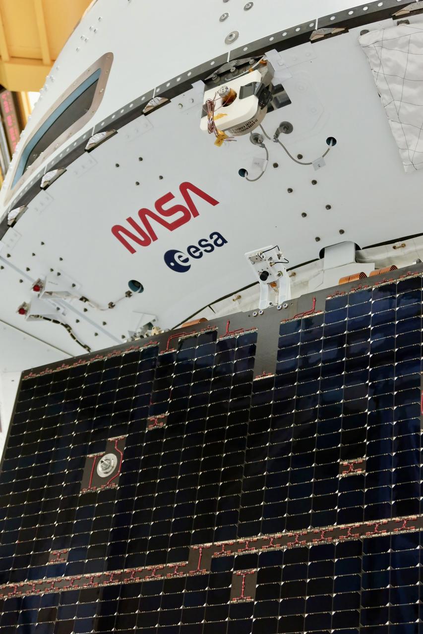
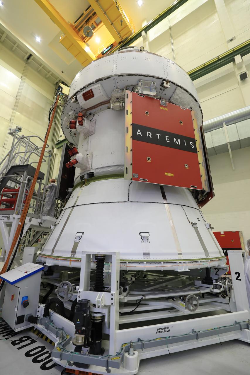
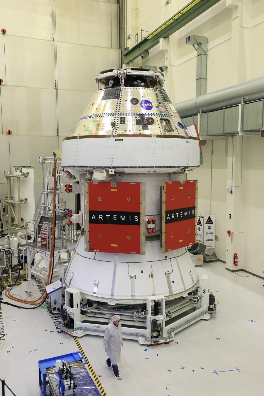
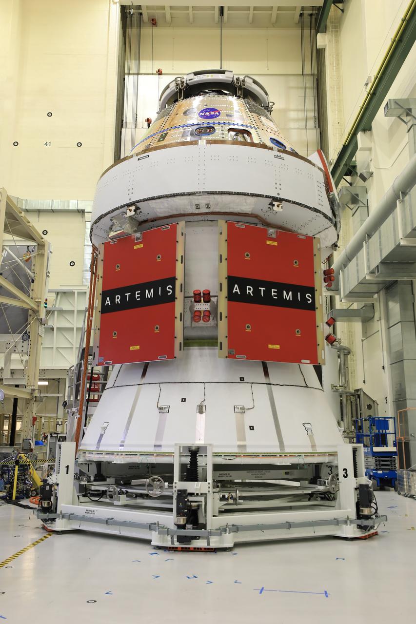
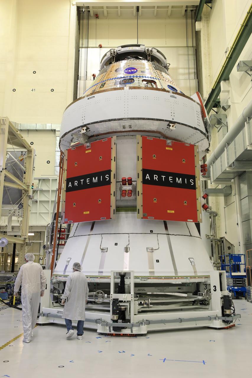
Technicians install four solar array wings on NASA’s Artemis II Orion spacecraft inside the Neil A. Armstrong Operations and Checkout Building at NASA’s Kennedy Space Center in Florida on Monday, March 3, 2025. Each solar array is nearly 23 feet long and can turn on two axes to remain aligned with the Sun for maximum power. Orion’s solar arrays, manufactured and installed by ESA (European Space Agency) and its contractor Airbus, will deliver power to the service module that provides propulsion, thermal control, and electrical power to the spacecraft, as well as air and water for the crew.
Technicians install four solar array wings on NASA’s Artemis II Orion spacecraft inside the Neil A. Armstrong Operations and Checkout Building at NASA’s Kennedy Space Center in Florida on Monday, March 3, 2025. Each solar array is nearly 23 feet long and can turn on two axes to remain aligned with the Sun for maximum power. Orion’s solar arrays, manufactured and installed by ESA (European Space Agency) and its contractor Airbus, will deliver power to the service module that provides propulsion, thermal control, and electrical power to the spacecraft, as well as air and water for the crew.
Technicians install four solar array wings on NASA’s Artemis II Orion spacecraft inside the Neil A. Armstrong Operations and Checkout Building at NASA’s Kennedy Space Center in Florida on Monday, March 3, 2025. Each solar array is nearly 23 feet long and can turn on two axes to remain aligned with the Sun for maximum power. Orion’s solar arrays, manufactured and installed by ESA (European Space Agency) and its contractor Airbus, will deliver power to the service module that provides propulsion, thermal control, and electrical power to the spacecraft, as well as air and water for the crew.
Technicians install four solar array wings on NASA’s Artemis II Orion spacecraft inside the Neil A. Armstrong Operations and Checkout Building at NASA’s Kennedy Space Center in Florida on Monday, March 3, 2025. Each solar array is nearly 23 feet long and can turn on two axes to remain aligned with the Sun for maximum power. Orion’s solar arrays, manufactured and installed by ESA (European Space Agency) and its contractor Airbus, will deliver power to the service module that provides propulsion, thermal control, and electrical power to the spacecraft, as well as air and water for the crew.
Technicians install four solar array wings on NASA’s Artemis II Orion spacecraft inside the Neil A. Armstrong Operations and Checkout Building at NASA’s Kennedy Space Center in Florida on Monday, March 3, 2025. Each solar array is nearly 23 feet long and can turn on two axes to remain aligned with the Sun for maximum power. Orion’s solar arrays, manufactured and installed by ESA (European Space Agency) and its contractor Airbus, will deliver power to the service module that provides propulsion, thermal control, and electrical power to the spacecraft, as well as air and water for the crew.
Technicians install four solar array wings on NASA’s Artemis II Orion spacecraft inside the Neil A. Armstrong Operations and Checkout Building at NASA’s Kennedy Space Center in Florida on Monday, March 3, 2025. Each solar array is nearly 23 feet long and can turn on two axes to remain aligned with the Sun for maximum power. Orion’s solar arrays, manufactured and installed by ESA (European Space Agency) and its contractor Airbus, will deliver power to the service module that provides propulsion, thermal control, and electrical power to the spacecraft, as well as air and water for the crew.
Technicians install four solar array wings on NASA’s Artemis II Orion spacecraft inside the Neil A. Armstrong Operations and Checkout Building at NASA’s Kennedy Space Center in Florida on Monday, March 3, 2025. Each solar array is nearly 23 feet long and can turn on two axes to remain aligned with the Sun for maximum power. Orion’s solar arrays, manufactured and installed by ESA (European Space Agency) and its contractor Airbus, will deliver power to the service module that provides propulsion, thermal control, and electrical power to the spacecraft, as well as air and water for the crew.
Technicians install four solar array wings on NASA’s Artemis II Orion spacecraft inside the Neil A. Armstrong Operations and Checkout Building at NASA’s Kennedy Space Center in Florida on Monday, March 3, 2025. Each solar array is nearly 23 feet long and can turn on two axes to remain aligned with the Sun for maximum power. Orion’s solar arrays, manufactured and installed by ESA (European Space Agency) and its contractor Airbus, will deliver power to the service module that provides propulsion, thermal control, and electrical power to the spacecraft, as well as air and water for the crew.
Technicians install four solar array wings on NASA’s Artemis II Orion spacecraft inside the Neil A. Armstrong Operations and Checkout Building at NASA’s Kennedy Space Center in Florida on Monday, March 3, 2025. Each solar array is nearly 23 feet long and can turn on two axes to remain aligned with the Sun for maximum power. Orion’s solar arrays, manufactured and installed by ESA (European Space Agency) and its contractor Airbus, will deliver power to the service module that provides propulsion, thermal control, and electrical power to the spacecraft, as well as air and water for the crew.
Technicians install four solar array wings on NASA’s Artemis II Orion spacecraft inside the Neil A. Armstrong Operations and Checkout Building at NASA’s Kennedy Space Center in Florida on Monday, March 3, 2025. Each solar array is nearly 23 feet long and can turn on two axes to remain aligned with the Sun for maximum power. Orion’s solar arrays, manufactured and installed by ESA (European Space Agency) and its contractor Airbus, will deliver power to the service module that provides propulsion, thermal control, and electrical power to the spacecraft, as well as air and water for the crew.
Technicians install four solar array wings on NASA’s Artemis II Orion spacecraft inside the Neil A. Armstrong Operations and Checkout Building at NASA’s Kennedy Space Center in Florida on Monday, March 3, 2025. Each solar array is nearly 23 feet long and can turn on two axes to remain aligned with the Sun for maximum power. Orion’s solar arrays, manufactured and installed by ESA (European Space Agency) and its contractor Airbus, will deliver power to the service module that provides propulsion, thermal control, and electrical power to the spacecraft, as well as air and water for the crew.
Technicians install four solar array wings on NASA’s Artemis II Orion spacecraft inside the Neil A. Armstrong Operations and Checkout Building at NASA’s Kennedy Space Center in Florida on Monday, March 3, 2025. Each solar array is nearly 23 feet long and can turn on two axes to remain aligned with the Sun for maximum power. Orion’s solar arrays, manufactured and installed by ESA (European Space Agency) and its contractor Airbus, will deliver power to the service module that provides propulsion, thermal control, and electrical power to the spacecraft, as well as air and water for the crew.
Technicians install four solar array wings on NASA’s Artemis II Orion spacecraft inside the Neil A. Armstrong Operations and Checkout Building at NASA’s Kennedy Space Center in Florida on Monday, March 3, 2025. Each solar array is nearly 23 feet long and can turn on two axes to remain aligned with the Sun for maximum power. Orion’s solar arrays, manufactured and installed by ESA (European Space Agency) and its contractor Airbus, will deliver power to the service module that provides propulsion, thermal control, and electrical power to the spacecraft, as well as air and water for the crew.
Technicians install four solar array wings on NASA’s Artemis II Orion spacecraft inside the Neil A. Armstrong Operations and Checkout Building at NASA’s Kennedy Space Center in Florida on Monday, March 3, 2025. Each solar array is nearly 23 feet long and can turn on two axes to remain aligned with the Sun for maximum power. Orion’s solar arrays, manufactured and installed by ESA (European Space Agency) and its contractor Airbus, will deliver power to the service module that provides propulsion, thermal control, and electrical power to the spacecraft, as well as air and water for the crew.
Technicians install four solar array wings on NASA’s Artemis II Orion spacecraft inside the Neil A. Armstrong Operations and Checkout Building at NASA’s Kennedy Space Center in Florida on Monday, March 3, 2025. Each solar array is nearly 23 feet long and can turn on two axes to remain aligned with the Sun for maximum power. Orion’s solar arrays, manufactured and installed by ESA (European Space Agency) and its contractor Airbus, will deliver power to the service module that provides propulsion, thermal control, and electrical power to the spacecraft, as well as air and water for the crew.
Technicians install four solar array wings on NASA’s Artemis II Orion spacecraft inside the Neil A. Armstrong Operations and Checkout Building at NASA’s Kennedy Space Center in Florida on Monday, March 3, 2025. Each solar array is nearly 23 feet long and can turn on two axes to remain aligned with the Sun for maximum power. Orion’s solar arrays, manufactured and installed by ESA (European Space Agency) and its contractor Airbus, will deliver power to the service module that provides propulsion, thermal control, and electrical power to the spacecraft, as well as air and water for the crew.
Technicians install four solar array wings on NASA’s Artemis II Orion spacecraft inside the Neil A. Armstrong Operations and Checkout Building at NASA’s Kennedy Space Center in Florida on Monday, March 3, 2025. Each solar array is nearly 23 feet long and can turn on two axes to remain aligned with the Sun for maximum power. Orion’s solar arrays, manufactured and installed by ESA (European Space Agency) and its contractor Airbus, will deliver power to the service module that provides propulsion, thermal control, and electrical power to the spacecraft, as well as air and water for the crew.
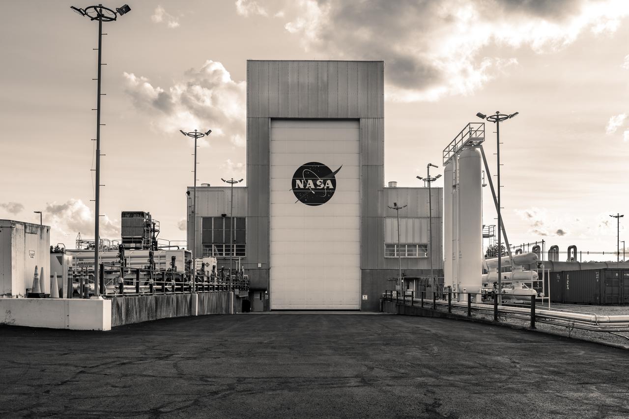
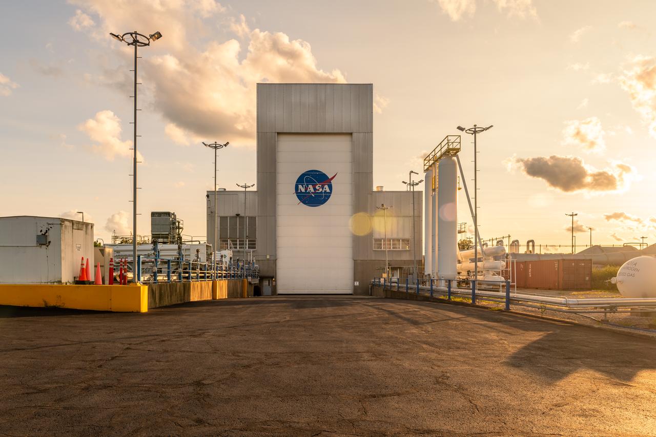
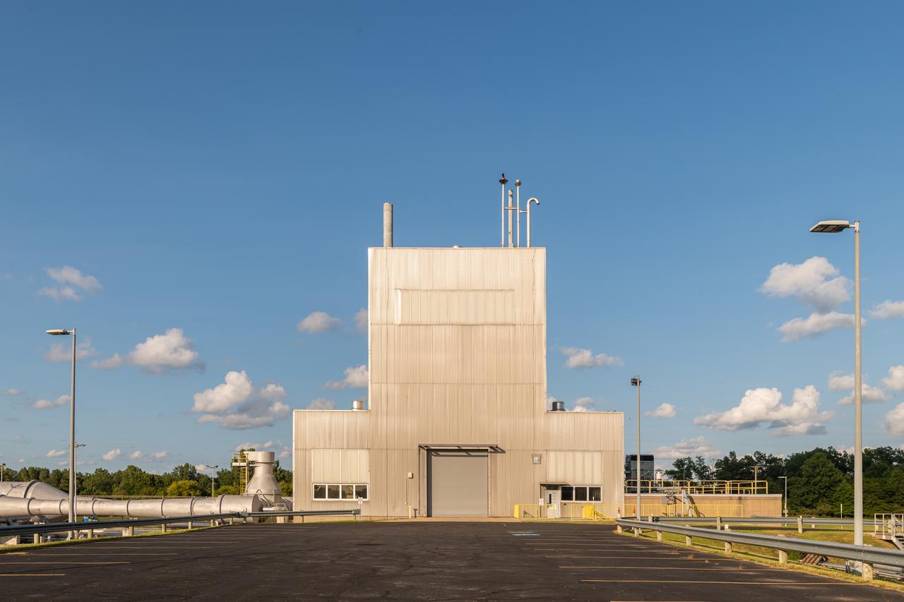
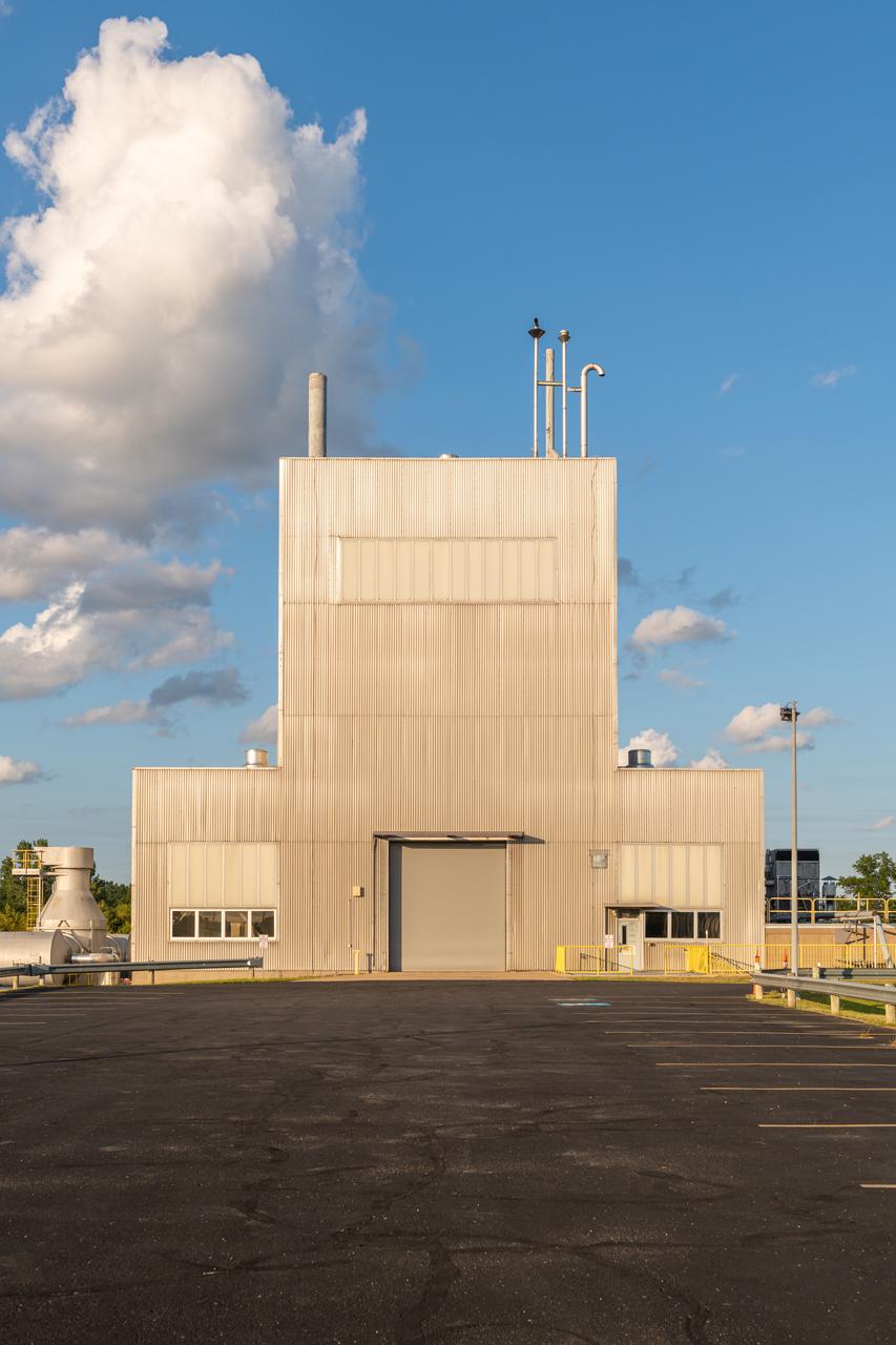
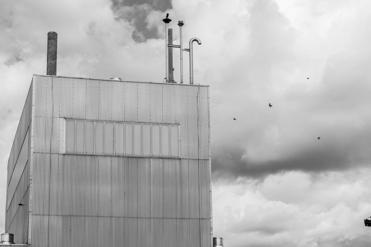
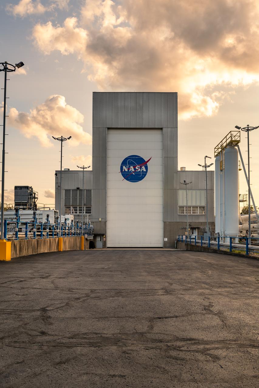
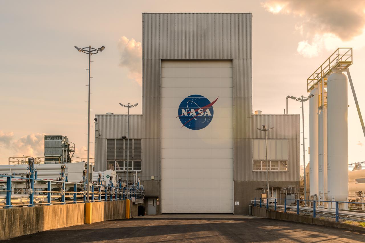
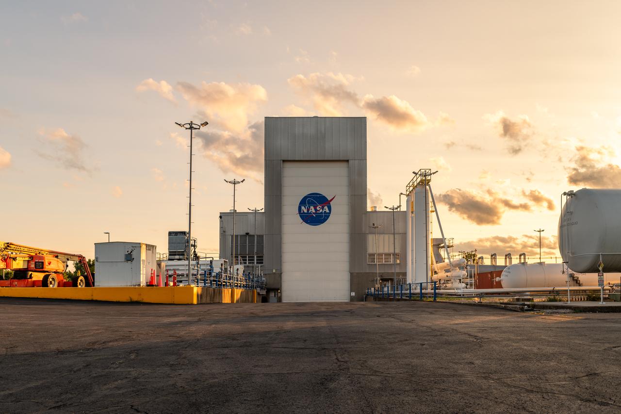
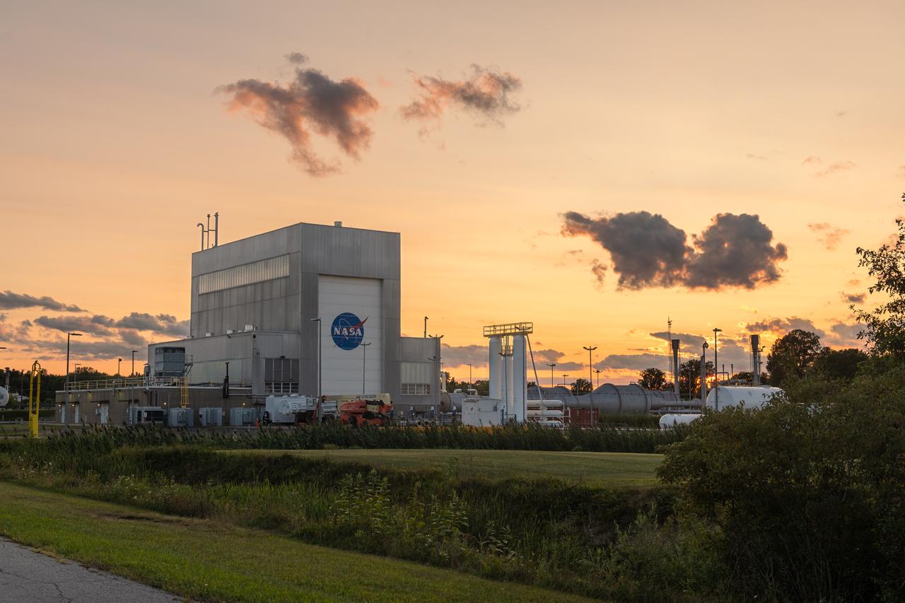
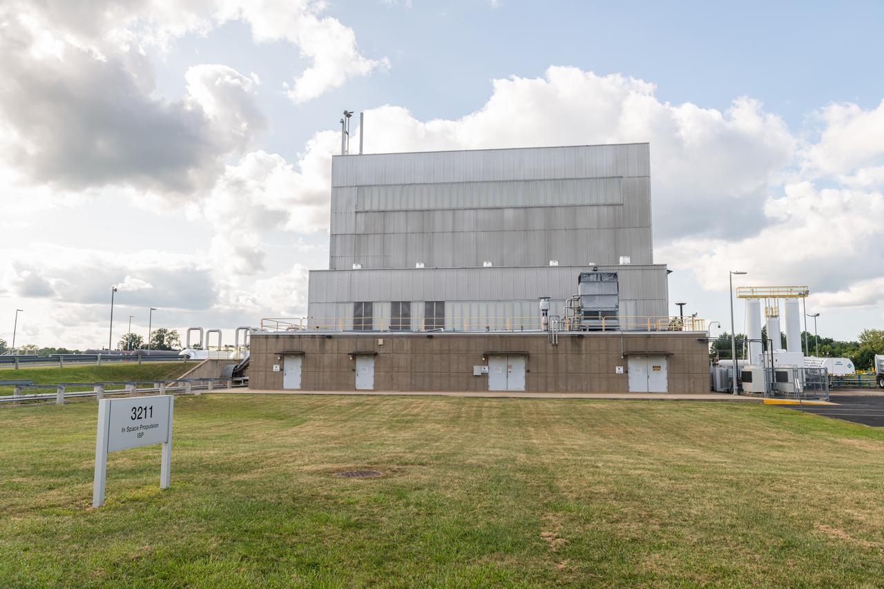
NASA’s In-Space Propulsion Facility located at Neil Armstrong Test Facility in Sandusky Ohio is the world’s only high altitude test facility capable of full-scale rocket engine and launch vehicle system level tests. The facility supports mission profile thermal vacuum simulation and engine firing. The engine or vehicle can be exposed for indefinite periods to low ambient pressures, low-background temperatures, and dynamic solar heating, simulating the environment the hardware will encounter during orbital or interplanetary travel. Photo Credit: (NASA/Jordan Salkin)
NASA’s In-Space Propulsion Facility located at Neil Armstrong Test Facility in Sandusky Ohio is the world’s only high altitude test facility capable of full-scale rocket engine and launch vehicle system level tests. The facility supports mission profile thermal vacuum simulation and engine firing. The engine or vehicle can be exposed for indefinite periods to low ambient pressures, low-background temperatures, and dynamic solar heating, simulating the environment the hardware will encounter during orbital or interplanetary travel. Photo Credit: (NASA/Jordan Salkin)
NASA’s In-Space Propulsion Facility located at Neil Armstrong Test Facility in Sandusky Ohio is the world’s only high altitude test facility capable of full-scale rocket engine and launch vehicle system level tests. The facility supports mission profile thermal vacuum simulation and engine firing. The engine or vehicle can be exposed for indefinite periods to low ambient pressures, low-background temperatures, and dynamic solar heating, simulating the environment the hardware will encounter during orbital or interplanetary travel. Photo Credit: (NASA/Jordan Salkin)
NASA’s In-Space Propulsion Facility located at Neil Armstrong Test Facility in Sandusky Ohio is the world’s only high altitude test facility capable of full-scale rocket engine and launch vehicle system level tests. The facility supports mission profile thermal vacuum simulation and engine firing. The engine or vehicle can be exposed for indefinite periods to low ambient pressures, low-background temperatures, and dynamic solar heating, simulating the environment the hardware will encounter during orbital or interplanetary travel. Photo Credit: (NASA/Jordan Salkin)
NASA’s In-Space Propulsion Facility located at Neil Armstrong Test Facility in Sandusky Ohio is the world’s only high altitude test facility capable of full-scale rocket engine and launch vehicle system level tests. The facility supports mission profile thermal vacuum simulation and engine firing. The engine or vehicle can be exposed for indefinite periods to low ambient pressures, low-background temperatures, and dynamic solar heating, simulating the environment the hardware will encounter during orbital or interplanetary travel. Photo Credit: (NASA/Jordan Salkin)
NASA’s In-Space Propulsion Facility located at Neil Armstrong Test Facility in Sandusky Ohio is the world’s only high altitude test facility capable of full-scale rocket engine and launch vehicle system level tests. The facility supports mission profile thermal vacuum simulation and engine firing. The engine or vehicle can be exposed for indefinite periods to low ambient pressures, low-background temperatures, and dynamic solar heating, simulating the environment the hardware will encounter during orbital or interplanetary travel. Photo Credit: (NASA/Jordan Salkin)
NASA’s In-Space Propulsion Facility located at Neil Armstrong Test Facility in Sandusky Ohio is the world’s only high altitude test facility capable of full-scale rocket engine and launch vehicle system level tests. The facility supports mission profile thermal vacuum simulation and engine firing. The engine or vehicle can be exposed for indefinite periods to low ambient pressures, low-background temperatures, and dynamic solar heating, simulating the environment the hardware will encounter during orbital or interplanetary travel. Photo Credit: (NASA/Jordan Salkin)
NASA’s In-Space Propulsion Facility located at Neil Armstrong Test Facility in Sandusky Ohio is the world’s only high altitude test facility capable of full-scale rocket engine and launch vehicle system level tests. The facility supports mission profile thermal vacuum simulation and engine firing. The engine or vehicle can be exposed for indefinite periods to low ambient pressures, low-background temperatures, and dynamic solar heating, simulating the environment the hardware will encounter during orbital or interplanetary travel. Photo Credit: (NASA/Jordan Salkin)
NASA’s In-Space Propulsion Facility located at Neil Armstrong Test Facility in Sandusky Ohio is the world’s only high altitude test facility capable of full-scale rocket engine and launch vehicle system level tests. The facility supports mission profile thermal vacuum simulation and engine firing. The engine or vehicle can be exposed for indefinite periods to low ambient pressures, low-background temperatures, and dynamic solar heating, simulating the environment the hardware will encounter during orbital or interplanetary travel. Photo Credit: (NASA/Jordan Salkin)
NASA’s In-Space Propulsion Facility located at Neil Armstrong Test Facility in Sandusky Ohio is the world’s only high altitude test facility capable of full-scale rocket engine and launch vehicle system level tests. The facility supports mission profile thermal vacuum simulation and engine firing. The engine or vehicle can be exposed for indefinite periods to low ambient pressures, low-background temperatures, and dynamic solar heating, simulating the environment the hardware will encounter during orbital or interplanetary travel. Photo Credit: (NASA/Jordan Salkin)
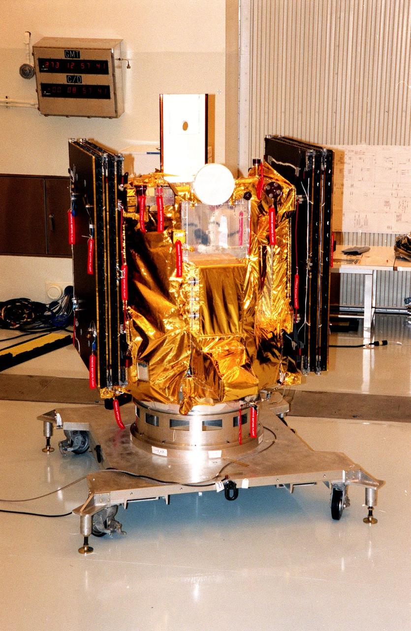
KENNEDY SPACE CENTER, FLA. -- Deep Space 1 rests on its work platform after being fitted with thermal insulation. The reflective insulation is designed to protect the spacecraft as this side faces the sun. At either side of the spacecraft are its solar wings, folded for launch. When fully extended, the wings measure 38.6 feet from tip to tip. The first flight in NASA's New Millennium Program, Deep Space 1 is designed to validate 12 new technologies for scientific space missions of the next century. Onboard experiments include a solar-powered ion propulsion engine and software that tracks celestial bodies so the spacecraft can make its own navigation decisions without the intervention of ground controllers. The ion propulsion engine is the first non-chemical propulsion to be used as the primary means of propelling a spacecraft. Deep Space 1 will complete most of its mission objectives within the first two months, but may also do a flyby of a near-Earth asteroid, 1992 KD, in July 1999. Deep Space 1 will be launched aboard a Boeing Delta 7326 rocket from Launch Pad 17A, Cape Canaveral Air Station, in October. Delta II rockets are medium capacity expendable launch vehicles derived from the Delta family of rockets built and launched since 1960. Since then there have been more than 245 Delta launches
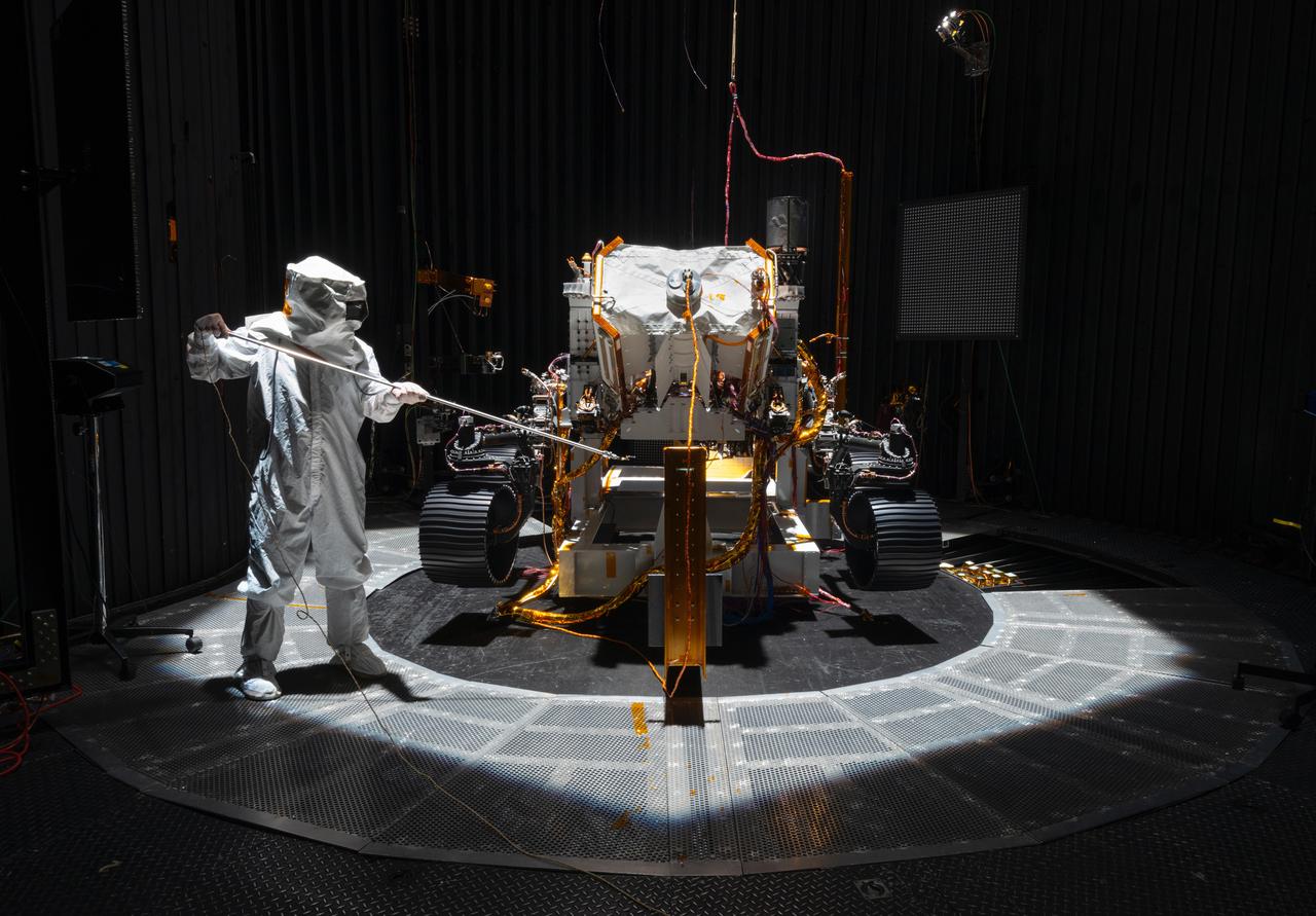
An engineer working on NASA's Mars 2020 mission uses a solar intensity probe to measure and compare the amount of artificial sunlight that reaches different portions of the rover. To simulate the Sun's rays for the test, powerful xenon lamps several floors below the chamber were illuminated, their light directed onto a mirror at the top of the chamber and reflected down on the spacecraft. The data collected during this test will be used to confirm thermal models the team has generated regarding how the Sun's rays will interact with the 2020 rover while on the surface of Mars. The image was taken on Oct. 14, 2019, in the Space Simulator Facility at NASA's Jet Propulsion Laboratory in Pasadena, California. https://photojournal.jpl.nasa.gov/catalog/PIA23469
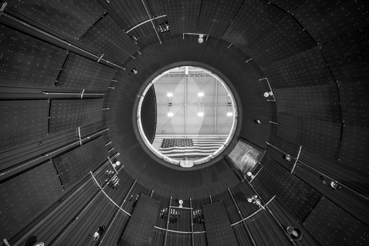
NASA’s In-Space Propulsion Facility located at Neil Armstrong Test Facility in Sandusky Ohio is the world’s only high altitude test facility capable of full-scale rocket engine and launch vehicle system level tests. The facility supports mission profile thermal vacuum simulation and engine firing. The engine or vehicle can be exposed for indefinite periods to low ambient pressures, low-background temperatures, and dynamic solar heating, simulating the environment the hardware will encounter during orbital or interplanetary travel. This is a view from inside the chamber looking up toward the American flag. Photo Credit: (NASA/Jordan Salkin)
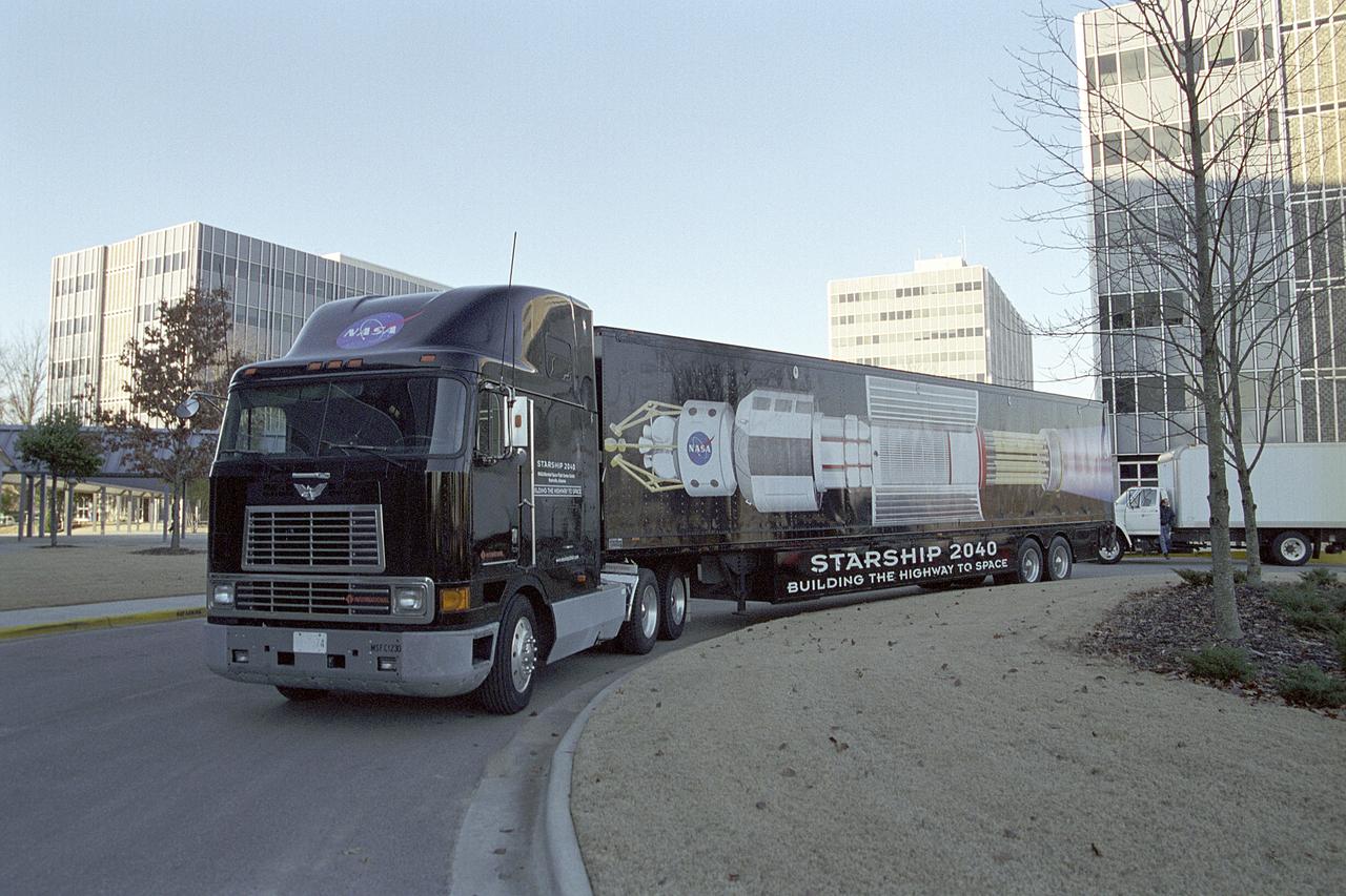
This photograph shows the Starship 2040 leaving the Marshall Space Flight Center (MSFC) for the exhibit site. Developed by the Space Transportation Directorate at MSFC, the Starship 2040 exhibit is housed in a 48-ft (14.6-m) tractor and trailer rig, permitting it to travel around the Nation, demonstrating NASA's vision of what commercial spaceflight might be like 40 years from now. All the irnovations suggested aboard the exhibit, automated vehicle health monitoring systems, high-energy propulsion drive, navigational aids and emergency and safety systems, are based on concepts and technologies now being studied at NASA Centers and partner institutions around the Nation. NASA is the nation's premier agency for development of the space transportation system, including future-generation reusable launch vehicles. Such systems, the keys to a "real" Starship 2040, require revolutionary advances in critical aerospace technologies, from thermal, magnetic, chemical, and propellantless propulsion systems to new energy sources such as space solar power or antimatter propulsion. These and other advances are now being studied, developed, and tested at NASA field centers and partner institutions all over the Nation.
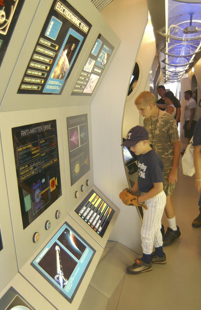
This photograph shows onlookers viewing displays within the Starship 2040 exhibit on display at Joe Davis Stadium in Huntsville, Alabama. Developed by the Space Transportation Directorate at Marshall Space Flight Center (MSFC), the Starship 2040 exhibit is housed in a 48-ft (14.6-m) tractor and trailer rig, permitting it to travel around the Nation, demonstrating NASA's vision of what commercial spaceflight might be like 40 years from now. All the irnovations suggested aboard the exhibit (automated vehicle health monitoring systems, high-energy propulsion drive, navigational aids, and emergency and safety systems) are based on concepts and technologies now being studied at NASA Centers and partner institutions around the Nation. NASA is the Nation's premier agency for development of the space transportation system, including future-generation reusable launch vehicles. Such systems, the keys to a "real" Starship 2040, require revolutionary advances in critical aerospace technologies, from thermal, magnetic, chemical, and propellantless propulsion systems to new energy sources such as space solar power or antimatter propulsion. These and other advances are now being studied, developed, and tested at NASA field centers and partner institutions all over the Nation.
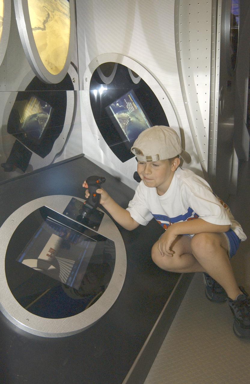
This photograph shows Justin Varnadore, son of a Marshall TV employee, at the controls of one of the many displays within the Starship 2040 exhibit on display at Joe Davis Stadium in Huntsville, Alabama. Developed by the Space Transportation Directorate at Marshall Space Flight Center (MSFC), the Starship 2040 exhibit is housed in a 48-ft (14.6-m) tractor and trailer rig, permitting it to travel around the Nation, demonstrating NASA's vision of what commercial spaceflight might be like 40 years from now. All the irnovations suggested aboard the exhibit (automated vehicle health monitoring systems, high-energy propulsion drive, navigational aids, and emergency and safety systems) are based on concepts and technologies now being studied at NASA Centers and partner institutions around the Nation. NASA is the Nation's premier agency for development of the space transportation system, including future-generation reusable launch vehicles. Such systems, the keys to a "real" Starship 2040, require revolutionary advances in critical aerospace technologies, from thermal, magnetic, chemical, and propellantless propulsion systems to new energy sources such as space solar power or antimatter propulsion. These and other advances are now being studied, developed, and tested at NASA field centers and partner institutions all over the Nation.
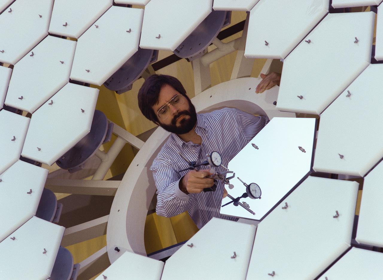
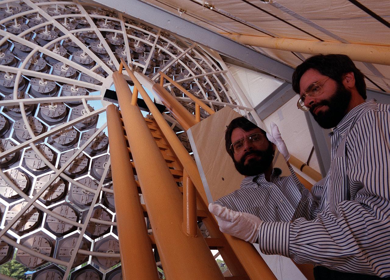
NASA's Space Optics Manufacturing Technology Center has been working to expand our view of the universe via sophisticated new telescopes. The Optics Center's goal is to develop low-cost, advanced space optics technologies for the NASA program in the 21st century, including the long-term goal of imaging Earth-like planets in distant solar systems. A segmented array of mirrors was designed by the Space Optics Manufacturing Technology Center for the solar concentrator test stand at the Marshall Space Flight Center (MSFC) for powering solar thermal propulsion engines. Each hexagon mirror has a spherical surface to approximate a parabolic concentrator when combined into the entire 18-foot diameter array. The aluminum mirrors were polished with a diamond turning machine that creates a glass-like reflective finish on metal. The precision fabrication machinery at the Space Optics Manufacturing Technology Center at MSFC can polish specialized optical elements to a world class quality of smoothness. This image shows optics physicist, Vince Huegele, examining one of the 144-segment hexagonal mirrors of the 18-foot diameter array at the MSFC solar concentrator test stand.
NASA's Space Optics Manufacturing Technology Center has been working to expand our view of the universe via sophisticated new telescopes. The Optics Center's goal is to develop low-cost, advanced space optics technologies for the NASA program in the 21st century, including the long-term goal of imaging Earth-like planets in distant solar systems. A segmented array of mirrors was designed by the Space Optics Manufacturing Technology Center for solar the concentrator test stand at the Marshall Space Flight Center (MSFC) for powering solar thermal propulsion engines. Each hexagon mirror has a spherical surface to approximate a parabolic concentrator when combined into the entire 18-foot diameter array. The aluminum mirrors were polished with a diamond turning machine, that creates a glass-like reflective finish on metal. The precision fabrication machinery at the Space Optics Manufacturing Technology Center at MSFC can polish specialized optical elements to a world class quality of smoothness. This image shows optics physicist, Vince Huegele, examining one of the 144-segment hexagonal mirrors of the 18-foot diameter array at the MSFC solar concentrator test stand.

Jet Propulsion Laboratory (JPL) technicians finish mounting a thermal model of a radioisotope thermoelectric generator (RTG) on the installation cart which will be used to install the RTG in the Cassini spacecraft at Level 14 of Space Launch Complex 40, Cape Canaveral Air Station. The technicians use the thermal model to practice installation procedures. The three actual RTGs which will provide electrical power to Cassini on its 6.7-mile trip to the Saturnian system, and during its four-year mission at Saturn, are being tested and monitored in the Radioisotope Thermoelectric Generator Storage Building in KSC's Industrial Area. The RTGs use heat from the natural decay of plutonium to generate electric power. RTGs enable spacecraft to operate far from the Sun where solar power systems are not feasible. The RTGs on Cassini are of the same design as those flying on the already deployed Galileo and Ulysses spacecraft. The Cassini mission is targeted for an October 6 launch aboard a Titan IVB/Centaur expendable launch vehicle. Cassini is built and managed for NASA by JPL
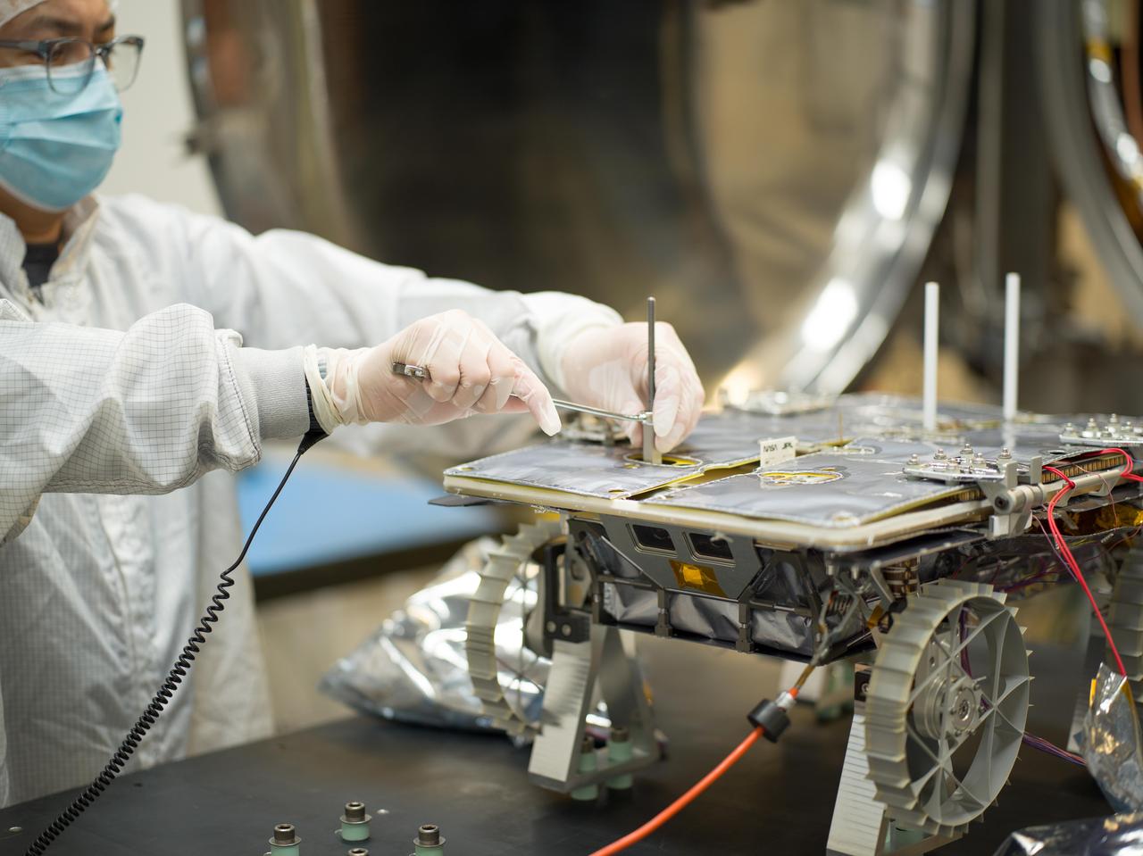
An engineer prepares a small rover – part of NASA's CADRE (Cooperative Autonomous Distributed Robotic Exploration) technology demonstration that's headed to the Moon – for testing in a thermal vacuum chamber at the agency's Jet Propulsion Laboratory in Southern California in October 2023. Slated to arrive at the Moon in 2024 as part of NASA's CLPS (Commercial Lunar Payload Services) initiative, CADRE is designed to demonstrate that multiple robots can cooperate and explore together autonomously – without direct input from human mission controllers. A trio of the miniature solar-powered rovers, each about the size of a carry-on suitcase, will explore the Moon as a team, communicating via radio with each other and a base station aboard a lunar lander. By taking simultaneous measurements from multiple locations, CADRE will also demonstrate how multirobot missions can record data impossible for a single robot to achieve – a tantalizing prospect for future missions. The rover being tested is the first flight model to be completed. Thermal vacuum testing simulates the harsh environment the rovers will face on the journey to the Moon and on the lunar surface: All the air is pumped out of the chamber and the temperature is cycled to high and low extremes. https://photojournal.jpl.nasa.gov/catalog/PIA25669
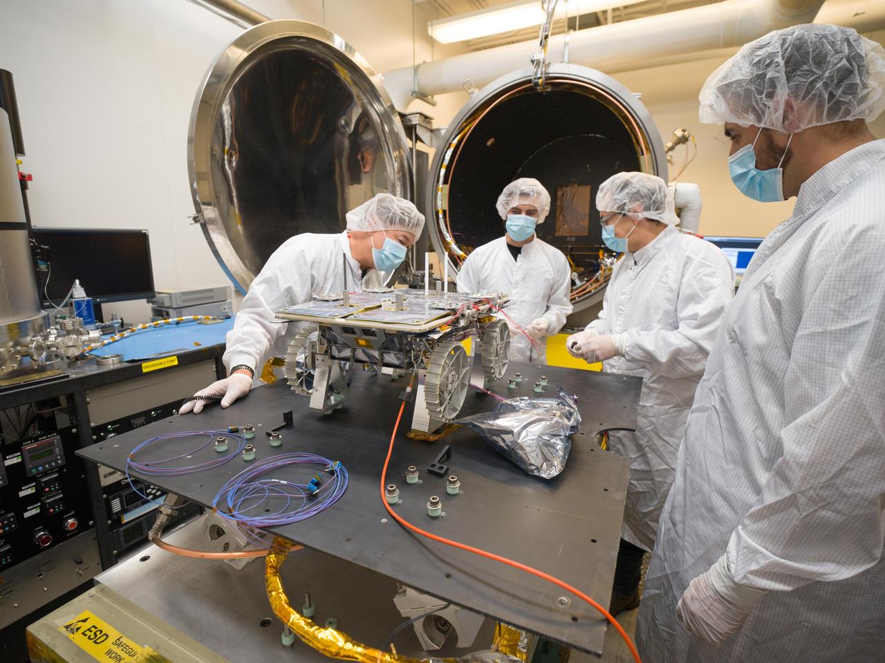
Engineers prepare a small rover – part of NASA's CADRE (Cooperative Autonomous Distributed Robotic Exploration) technology demonstration that's headed to the Moon – for testing in the thermal vacuum chamber behind them at the agency's Jet Propulsion Laboratory in Southern California in October 2023. Slated to arrive at the Moon in 2024 as part of NASA's CLPS (Commercial Lunar Payload Services) initiative, CADRE is designed to demonstrate that multiple robots can cooperate and explore together autonomously – without direct input from human mission controllers. A trio of the miniature solar-powered rovers, each about the size of a carry-on suitcase, will explore the Moon as a team, communicating via radio with each other and a base station aboard a lunar lander. By taking simultaneous measurements from multiple locations, CADRE will also demonstrate how multirobot missions can record data impossible for a single robot to achieve – a tantalizing prospect for future missions. The rover being tested is the first flight model to be completed. Thermal vacuum testing simulates the harsh environment the rovers will face on the journey to the Moon and on the lunar surface: All the air is pumped out of the chamber and the temperature is cycled to high and low extremes. https://photojournal.jpl.nasa.gov/catalog/PIA25670
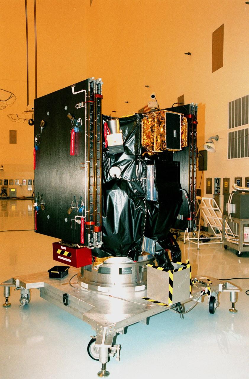
KENNEDY SPACE CENTER, FLA. -- Deep Space 1 rests on its work platform after being fitted with thermal insulation. The dark insulation is designed to protect the side of the spacecraft that faces away from the sun. At either side of the spacecraft are its solar wings, folded for launch. When fully extended, the wings measure 38.6 feet from tip to tip. The first flight in NASA's New Millennium Program, Deep Space 1 is designed to validate 12 new technologies for scientific space missions of the next century. Onboard experiments include a solar-powered ion propulsion engine and software that tracks celestial bodies so the spacecraft can make its own navigation decisions without the intervention of ground controllers. The ion propulsion engine is the first non-chemical propulsion to be used as the primary means of propelling a spacecraft. Deep Space 1 will complete most of its mission objectives within the first two months, but may also do a flyby of a near-Earth asteroid, 1992 KD, in July 1999. Deep Space 1 will be launched aboard a Boeing Delta 7326 rocket from Launch Pad 17A, Cape Canaveral Air Station, in October. Delta II rockets are medium capacity expendable launch vehicles derived from the Delta family of rockets built and launched since 1960. Since then there have been more than 245 Delta launches
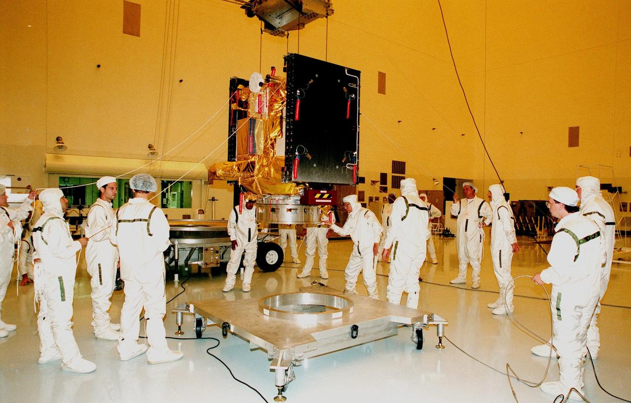
KENNEDY SPACE CENTER, FLA. -- After covering the bulk of Deep Space 1 in thermal insulating blankets, workers in the Payload Hazardous Servicing Facility lift it from its work platform before moving it onto its transporter (behind workers at left). Deep Space 1 is being moved to the Defense Satellite Communications System Processing Facility (DPF), Cape Canaveral Air Station, for testing. At either side of the spacecraft are its solar wings, folded for launch. When fully extended, the wings measure 38.6 feet from tip to tip. The first flight in NASA's New Millennium Program, Deep Space 1 is designed to validate 12 new technologies for scientific space missions of the next century. Onboard experiments include a solar-powered ion propulsion engine and software that tracks celestial bodies so the spacecraft can make its own navigation decisions without the intervention of ground controllers. The ion propulsion engine is the first non-chemical propulsion to be used as the primary means of propelling a spacecraft. Deep Space 1 will complete most of its mission objectives within the first two months, but may also do a flyby of a near-Earth asteroid, 1992 KD, in July 1999. Deep Space 1 will be launched aboard a Boeing Delta 7326 rocket from Launch Pad 17A, Cape Canaveral Air Station, in October. Delta II rockets are medium capacity expendable launch vehicles derived from the Delta family of rockets built and launched since 1960. Since then there have been more than 245 Delta launches
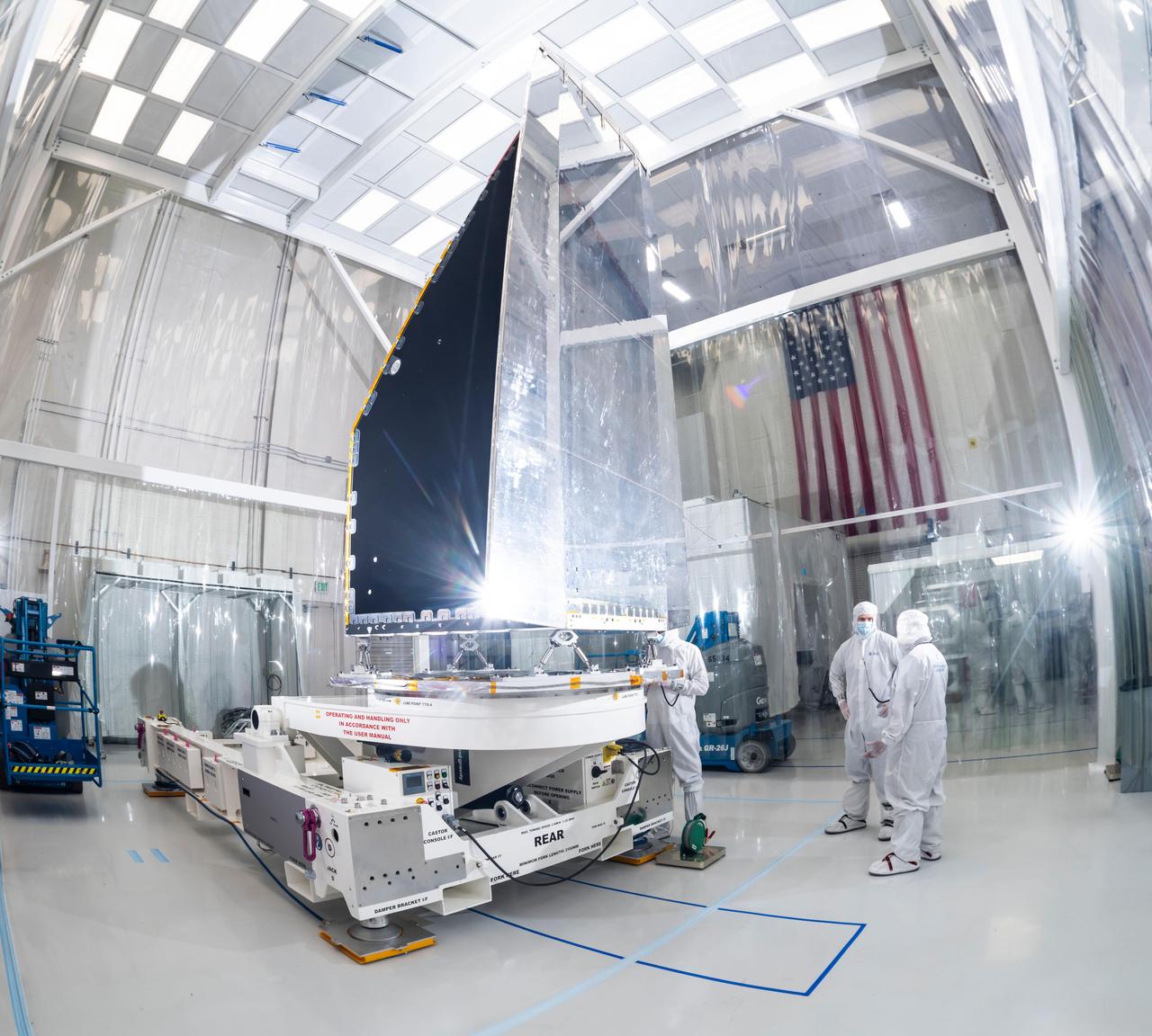
The Solar Electric Propulsion (SEP) Chassis of NASA's Psyche spacecraft is mounted onto a rotation fixture in High Bay 1 of the Spacecraft Assembly Facility at NASA's Jet Propulsion Laboratory in Southern California. This photo was taken March 28, 2021, just after the chassis — a major component of the Psyche spacecraft — was delivered to JPL by Maxar Technologies. Maxar's team in Palo Alto, California, designed and built the chassis, which includes all the primary and secondary structure and the hardware components needed for the high-power electrical system, the propulsion system, the thermal system, guidance and navigation sensors and actuators, and the high-gain antenna. The phase known as assembly test, and launch operations (ATLO) for Psyche is now underway at JPL. In this photo, ATLO Mechanical Lead Michelle Colizzi of JPL oversees the docking of the chassis to the dolly. Over the next year additional hardware will be added to the spacecraft including the command and data handling system, a power distribution assembly, the X-band telecommunications hardware suite, three science instruments (two imagers, two magnetometers, and a Gamma Ray Neutron Spectrometer), and a deep space optical communications technology demonstrator. The spacecraft will finish assembly and then undergo rigorous checkout and testing, before it's shipped to NASA's Kennedy Space Center in Cape Canaveral, Florida, for an August 2022 launch to the main asteroid belt. Psyche will arrive at the metal-rich asteroid of the same name in 2026, orbiting for 21 months to investigate its composition. Scientists think that Psyche is made up of mostly iron and nickel — similar to Earth's core. Exploring the asteroid could give valuable insight into how our own planet and others formed. https://photojournal.jpl.nasa.gov/catalog/PIA24476
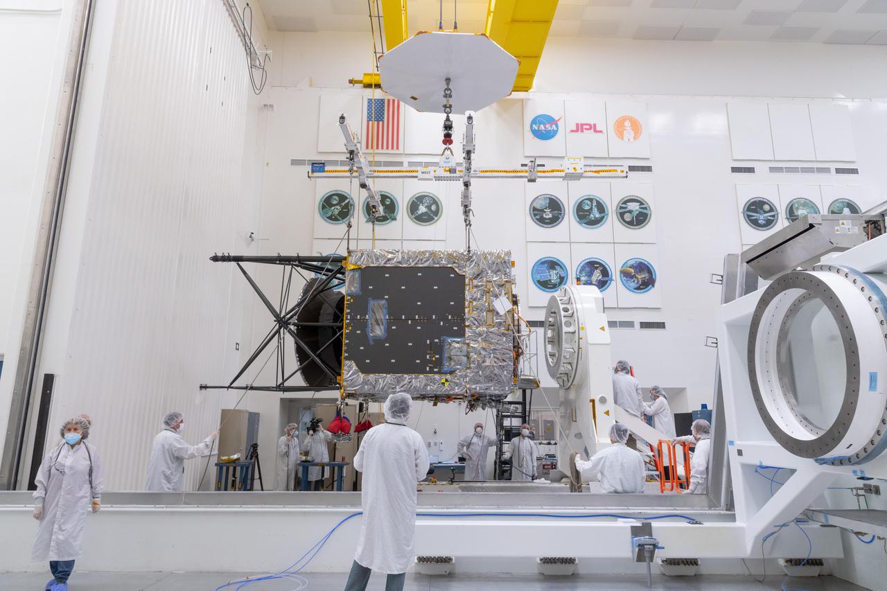
A major component of NASA's Psyche spacecraft has been delivered to the agency's Jet Propulsion Laboratory in Southern California, where the phase known as assembly, test, and launch operations (ATLO) is now underway. Taken on March 28, 2021, this photo shows the Solar Electric Propulsion (SEP) Chassis just after it was delivered to JPL by Maxar Technologies. Here, the chassis is about to be attached to the dolly in High Bay 1 of JPL's Spacecraft Assembly Facility. Maxar's team in Palo Alto, California, designed and built the SEP Chassis, which includes all the primary and secondary structure and the hardware components needed for the high-power electrical system, the propulsion system, the thermal system, guidance and navigation sensors and actuators, and the high-gain antenna. Over the next year additional hardware will be added to the spacecraft, including the command and data handling system, a power distribution assembly, the X-band telecommunications hardware suite, three science instruments (two imagers, two magnetometers, and a Gamma Ray Neutron Spectrometer), and a deep space optical communications technology demonstrator. The spacecraft will finish assembly and then undergo rigorous checkout and testing before being shipped to NASA's Kennedy Space Center in Cape Canaveral, Florida, for an August 2022 launch to the main asteroid belt. Psyche will arrive at the metal-rich asteroid of the same name in 2026, orbiting for 21 months to investigate its composition. Scientists think that Psyche is made up of mostly iron and nickel — similar to Earth's core. Exploring the asteroid could give valuable insight into how our own planet and others formed. https://photojournal.jpl.nasa.gov/catalog/PIA24474

A major component of NASA's Psyche spacecraft has been delivered to NASA's Jet Propulsion Laboratory in Southern California, where the phase known as assembly, test, and launch operations (ATLO) is now underway. This photo, shot March 28, 2021 shows engineers and technicians preparing to move the Solar Electric Propulsion (SEP) Chassis from its shipping container to a dolly in High Bay 1 of JPL's Spacecraft Assembly Facility. The photo was captured just after the chassis was delivered to JPL by Maxar Technologies. Maxar's team in Palo Alto, California, designed and built the SEP Chassis, which includes all the primary and secondary structure and the hardware components needed for the high-power electrical system, the propulsion system, the thermal system, guidance and navigation sensors and actuators, and the high-gain antenna. Over the next year, additional hardware will be added to the spacecraft including the command and data handling system, a power distribution assembly, the X-band telecommunications hardware suite, three science instruments (two imagers, two magnetometers, and a gamma ray neutron Spectrometer), and a deep space optical communications technology demonstrator. The spacecraft will finish assembly and then undergo rigorous checkout and testing before being shipped to NASA's Kennedy Space Center in Cape Canaveral, Florida, for an August 2022 launch to the main asteroid belt. Psyche will arrive at the metal-rich asteroid of the same name in 2026, orbiting for 21 months to investigate its composition. Scientists think that Psyche is made up of mostly iron and nickel — similar to Earth's core. Exploring the asteroid could give valuable insight into how our own planet and others formed. https://photojournal.jpl.nasa.gov/catalog/PIA24475
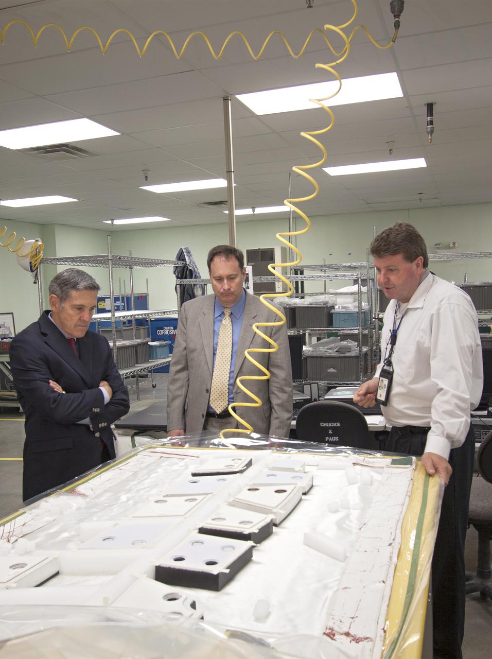
CAPE CANAVERAL, Fla. – NASA Associate Administrator Robert Lightfoot, center, tours the Thermal Protection System Facility, or TPSF, during a visit to NASA's Kennedy Space Center in Florida. From left are Kennedy Director Bob Cabana, Lightfoot, and Martin Boyd, TPSF manager with Jacobs Technologies, briefing his guests on the production of TPS tile for NASA's new Orion spacecraft. NASA's FY2014 budget proposal includes a plan to robotically capture a small near-Earth asteroid and redirect it safely to a stable orbit in the Earth-moon system where astronauts can visit and explore it. Performing these elements for the proposed asteroid initiative integrates the best of NASA's science, technology and human exploration capabilities and draws on the innovation of America's brightest scientists and engineers. It uses current and developing capabilities to find both large asteroids that pose a hazard to Earth and small asteroids that could be candidates for the initiative, accelerates our technology development activities in high-powered solar electric propulsion and takes advantage of our hard work on the Space Launch System rocket and Orion spacecraft, helping to keep NASA on target to reach the President's goal of sending humans to Mars in the 2030s. Photo credit: NASA_Jim Grossmann
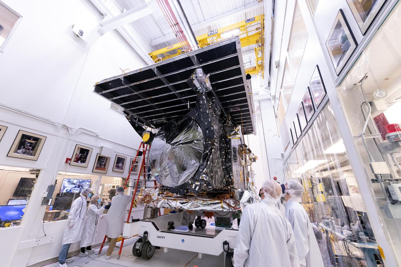
NASA's Psyche spacecraft is seen in early 2022 on its way to the vacuum chamber at the agency's Jet Propulsion Laboratory in Southern California. Thermal-vacuum (TVAC) testing is part of a regimen of environmental tests that are crucial for ensuring the spacecraft can survive the extreme conditions of launch and outer space. The orbiter will travel 1.5 billion miles (2.4 billion kilometers) to its target in the main asteroid belt, a metal-rich asteroid also called Psyche. Scientists believe the asteroid could be part or all of the iron-rich interior of an early planetary building block that was stripped of its outer rocky shell in the early days of the solar system. Over 18 days of TVAC testing, engineers exposed the spacecraft to the coldest and warmest conditions it will experience in flight, to prove that it is capable of regulating its own temperature. All of the air was sucked out of the chamber to replicate the airless vacuum of space. This test ensures that the spacecraft can survive the vacuum of space, and it helps engineers see how the spacecraft heats and cools itself without the movement of air to help it regulate temperature. Psyche is set to launch in August 2022. https://photojournal.jpl.nasa.gov/catalog/PIA25231
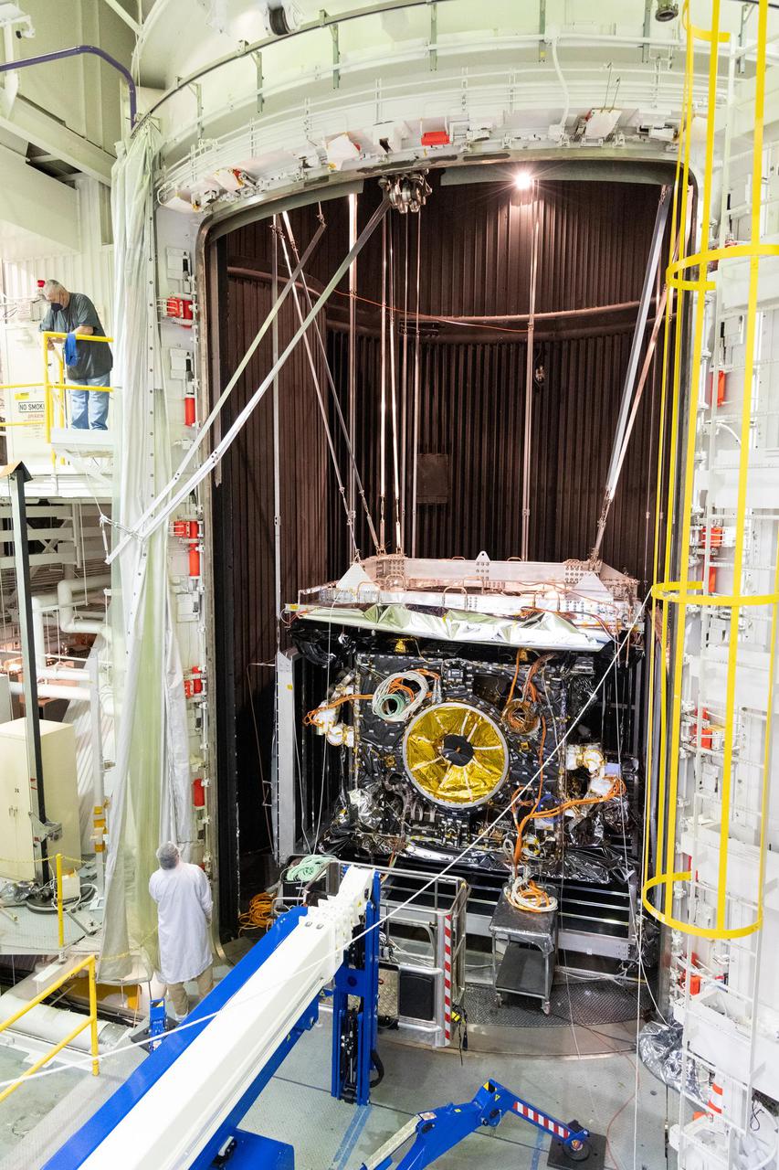
NASA's Psyche spacecraft is seen in early 2022 as it is placed in the 85-foot-tall, 25-foot-wide (26-meter-by-8-meter) ultra-sturdy vacuum chamber at the agency's Jet Propulsion Laboratory in Southern California. Thermal-vacuum (TVAC) testing is part of a regimen of environmental tests that are crucial for ensuring the spacecraft can survive the extreme conditions of launch and outer space. The orbiter will travel 1.5 billion miles (2.4 billion kilometers) to its target in the main asteroid belt, a metal-rich asteroid also called Psyche. Scientists believe the asteroid could be part or all of the iron-rich interior of an early planetary building block that was stripped of its outer rocky shell in the early days of the solar system. Over 18 days of TVAC testing, engineers exposed the spacecraft to the coldest and warmest conditions it will experience in flight, to prove that it is capable of regulating its own temperature. All of the air was sucked out of the chamber to replicate the airless vacuum of space. This test ensures that the spacecraft can survive the vacuum of space, and it helps engineers see how the spacecraft heats and cools itself without the movement of air to help it regulate temperature. Psyche is set to launch in August 2022. https://photojournal.jpl.nasa.gov/catalog/PIA25232

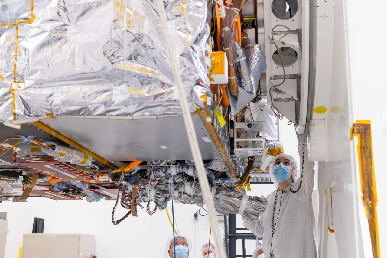
The instrument enclosure of NASA's Near-Earth Object Surveyor is prepared for critical environmental tests inside the historic Chamber A at the Space Environment Simulation Laboratory at the agency's Johnson Space Center in Houston in December 2024. Wrapped in silver thermal blanketing, the 12-foot-long (3.7-meter-long) angular structure was subjected to the frigid, airless conditions that the spacecraft will experience when in deep space. The cavernous thermal-vacuum test facility is famous for testing the Apollo spacecraft that traveled to the Moon in the 1960s and '70s. The instrument enclosure is designed to protect the spacecraft's infrared telescope while also removing heat from it during operations. After environmental testing was completed, the enclosure returned to NASA's Jet Propulsion Laboratory in Southern California for further work, after which it will ship to the Space Dynamics Laboratory (SDL) in Logan, Utah, and be joined to the telescope. Both the instrument enclosure and telescope were assembled at JPL. As NASA's first space-based detection mission specifically designed for planetary defense, NEO Surveyor will seek out, measure, and characterize the hardest-to-find asteroids and comets that might pose a hazard to Earth. While many near-Earth objects don't reflect much visible light, they glow brightly in infrared light due to heating by the Sun. The spacecraft's telescope, which has an aperture of nearly 20 inches (50 centimeters), features detectors sensitive to two infrared wavelengths in which near-Earth objects re-radiate solar heat. Targeting launch in late 2027, the NEO Surveyor mission is led by Prof. Amy Mainzer at UCLA for NASA's Planetary Defense Coordination Office and is being managed by JPL for the Planetary Missions Program Office at NASA's Marshall Space Flight Center in Huntsville, Alabama. BAE Systems, SDL, and Teledyne are among the companies that were contracted to build the spacecraft and its instrumentation. The Laboratory for Atmospheric and Space Physics at the University of Colorado Boulder will support operations, and Caltech/IPAC in Pasadena, California, is responsible for producing some of the mission's data products. Caltech manages JPL for NASA. https://photojournal.jpl.nasa.gov/catalog/PIA26583

Hamelin Pool Marine Nature Reserve is located in the Shark Bay World Heritage Site in Western Australia. It is one of the very few places in the world where living stromatolites can be found. These are the first living examples of structures built by cyanobacteria. These bacteria are direct descendants of the oldest form of photosynthetic life on earth, dating back 3,500 million years (Wikipedia). The image was acquired December 30, 2010, covers an area of 34 x 46 km, and is located at 26.4 degrees south latitude, 114.1 degrees east longitude. With its 14 spectral bands from the visible to the thermal infrared wavelength region and its high spatial resolution of 15 to 90 meters (about 50 to 300 feet), ASTER images Earth to map and monitor the changing surface of our planet. ASTER is one of five Earth-observing instruments launched Dec. 18, 1999, on Terra. The instrument was built by Japan's Ministry of Economy, Trade and Industry. A joint U.S./Japan science team is responsible for validation and calibration of the instrument and data products. The broad spectral coverage and high spectral resolution of ASTER provides scientists in numerous disciplines with critical information for surface mapping and monitoring of dynamic conditions and temporal change. Example applications are: monitoring glacial advances and retreats; monitoring potentially active volcanoes; identifying crop stress; determining cloud morphology and physical properties; wetlands evaluation; thermal pollution monitoring; coral reef degradation; surface temperature mapping of soils and geology; and measuring surface heat balance. The U.S. science team is located at NASA's Jet Propulsion Laboratory, Pasadena, Calif. The Terra mission is part of NASA's Science Mission Directorate, Washington, D.C. More information about ASTER is available at <a href="http://asterweb.jpl.nasa.gov/" rel="nofollow">asterweb.jpl.nasa.gov/</a>. Credit: NASA/GSFC/METI/ERSDAC/JAROS, and U.S./Japan ASTER Science Team Image Addition Date: 2013-03-15 <b><a href="http://www.nasa.gov/audience/formedia/features/MP_Photo_Guidelines.html" rel="nofollow">NASA image use policy.</a></b> <b><a href="http://www.nasa.gov/centers/goddard/home/index.html" rel="nofollow">NASA Goddard Space Flight Center</a></b> enables NASA’s mission through four scientific endeavors: Earth Science, Heliophysics, Solar System Exploration, and Astrophysics. Goddard plays a leading role in NASA’s accomplishments by contributing compelling scientific knowledge to advance the Agency’s mission. <b>Follow us on <a href="http://twitter.com/NASA_GoddardPix" rel="nofollow">Twitter</a></b> <b>Like us on <a href="http://www.facebook.com/pages/Greenbelt-MD/NASA-Goddard/395013845897?ref=tsd" rel="nofollow">Facebook</a></b> <b>Find us on <a href="http://instagram.com/nasagoddard?vm=grid" rel="nofollow">Instagram</a></b>
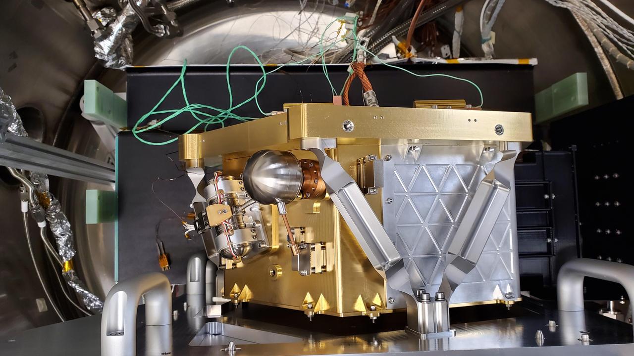
After arriving at the Space Dynamics Laboratory (SDL) in Logan, Utah, from NASA's Jet Propulsion Laboratory in Southern California in May 2025, the instrument enclosure for the agency's Near-Earth Object (NEO) Surveyor mission was inspected prior to thermal vacuum testing. Shown here, the enclosure stands vertically atop an articulating assembly dolly. The shiny and black surfaces of the enclosure optimize the reflection and radiation properties of the structure. The telescope, which has an aperture of nearly 20 inches (50 centimeters), features detectors sensitive to two infrared wavelengths in which near-Earth objects re-radiate solar heat. The instrument enclosure is designed to ensure heat produced by the telescope during operations doesn't interfere with its observations. As NASA's first space-based detection mission specifically designed for planetary defense, NEO Surveyor will seek out, measure, and characterize the hardest-to-find asteroids and comets that might pose a hazard to Earth. While many near-Earth objects don't reflect much visible light, they glow brightly in infrared light due to heating by the Sun. Targeting launch in late 2027, the NEO Surveyor mission is led by Professor Amy Mainzer at UCLA for NASA's Planetary Defense Coordination Office and is being managed by JPL for the Planetary Missions Program Office at NASA's Marshall Space Flight Center in Huntsville, Alabama. BAE Systems, SDL, and are among the companies that were contracted to build the spacecraft and its instrumentation. The Laboratory for Atmospheric and Space Physics at the University of Colorado Boulder will support operations, and IPAC at Caltech in Pasadena, California, is responsible for producing some of the mission's data products. Caltech manages JPL for NASA. https://photojournal.jpl.nasa.gov/catalog/PIA26597
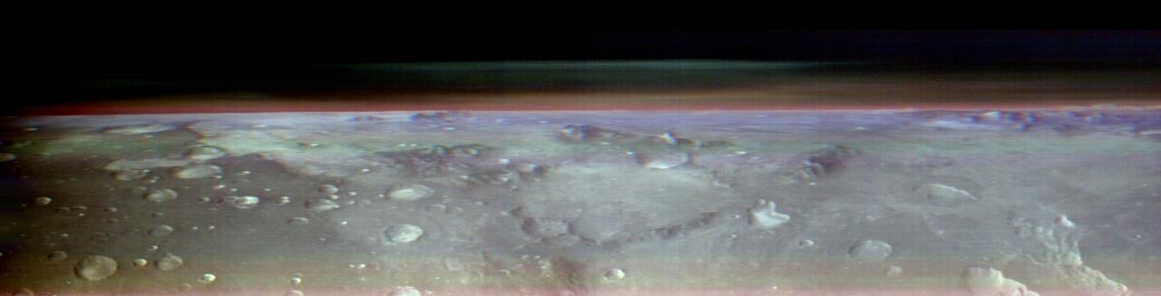
This view of Mars was captured by NASA's Odyssey orbiter using its Thermal Emission Imaging System, or THEMIS, camera. This image is a false color composite, made by combining three channels of infrared data that highlight water-ice clouds and dust in the atmosphere. This panorama was one of 10 captured on May 9, 2023, from an altitude of roughly 250 miles (400 kilometers) above the Martian surface – about the same altitude at which the International Space Station flies over Earth. The 10 panoramas of the Martian horizon were taken to capture a one-of-a-kind view of the Martian atmosphere as Odyssey circled the planet during its two-hour orbit. The reason why the view is so uncommon is because of the challenges involved in creating it. Engineers at NASA's Jet Propulsion Laboratory in Southern California (which leads the Odyssey mission) and Lockheed Martin Space (which built Odyssey and co-leads day-to-day operations) spent three months planning the observations. THEMIS' sensitivity to warmth enables it to map ice, rock, sand, and dust, along with temperature changes, on the planet's surface. It can also measure how much water ice or dust is in the atmosphere, but only in a narrow column directly below the spacecraft. That's because THEMIS is fixed in place on the orbiter; it usually points straight down. Mission scientists wanted a more expansive view of the atmosphere. Seeing where those layers of water-ice clouds and dust are in relation to each other – whether there's one layer or several stacked on top of each other – helps them improve models of Mars' atmosphere. Because THEMIS can't pivot, adjusting the angle of the camera requires adjusting the position of the whole spacecraft. In this case, the team needed to rotate the orbiter almost 90 degrees while making sure the Sun would still shine on the spacecraft's solar panels but not on sensitive equipment that could overheat. The easiest orientation turned out to be one where the orbiter's antenna pointed away from Earth. That meant the team was out of communication with Odyssey for several hours until the operation was completed. https://photojournal.jpl.nasa.gov/catalog/PIA26203
The High-resolution Volatiles and Minerals Moon Mapper (HVM³), seen here, is one of two instruments that will be carried aboard NASA's Lunar Trailblazer. Launching in 2023, the small spacecraft – measuring only 11.5 feet (3.5 meters) wide with its solar panels fully deployed – will detect and map water on the Moon's surface to determine its abundance, location, form, and how it changes over time. HVM³ recently completed a significant milestone in a clean room at NASA's Jet Propulsion Laboratory in Southern California. The high-resolution spectrometer measures the infrared light (with wavelengths from 0.6 to 3.6 microns in size) that is absorbed by water. To make sure the instrument is properly aligned, the Trailblazer team cooled HVM3 down to temperatures it will experience in space and made tiny physical adjustments to make sure all the wavelengths of incoming light arrive at the correct locations on the instrument's detector. Figure A shows several members of the Trailblazer team surrounding the instrument – minus its radiator and electronics – mounted on HVM³'s optical bench assembly while undergoing cold alignment. The assembly was placed inside a thermal vacuum chamber and brought to a cold focal plane operating temperature of about minus 240 degrees Fahrenheit (minus 155 degrees Celsius). The team then measured light of different wavelengths across all of the detector's pixels. Based on the data recorded, the team calculated the small adjustments that needed to be made, took the instrument out of the chamber and made those changes, placed it back into the chamber, and then repeated the steps iteratively until HVM³ was in perfect alignment. With this important step complete, a radiator will next be installed to ensure the instrument maintains optimal operating temperatures while Trailblazer is in orbit around the Moon. Then, vibration tests will be carried out to make sure the spectrometer will stay in alignment after the extreme shaking of launch. Lunar Trailblazer was selected to be part of NASA's SIMPLEx (Small Innovative Missions for Planetary Exploration) program in 2019. The mission is led by Caltech in Pasadena, California, and managed by JPL. https://photojournal.jpl.nasa.gov/catalog/PIA25252
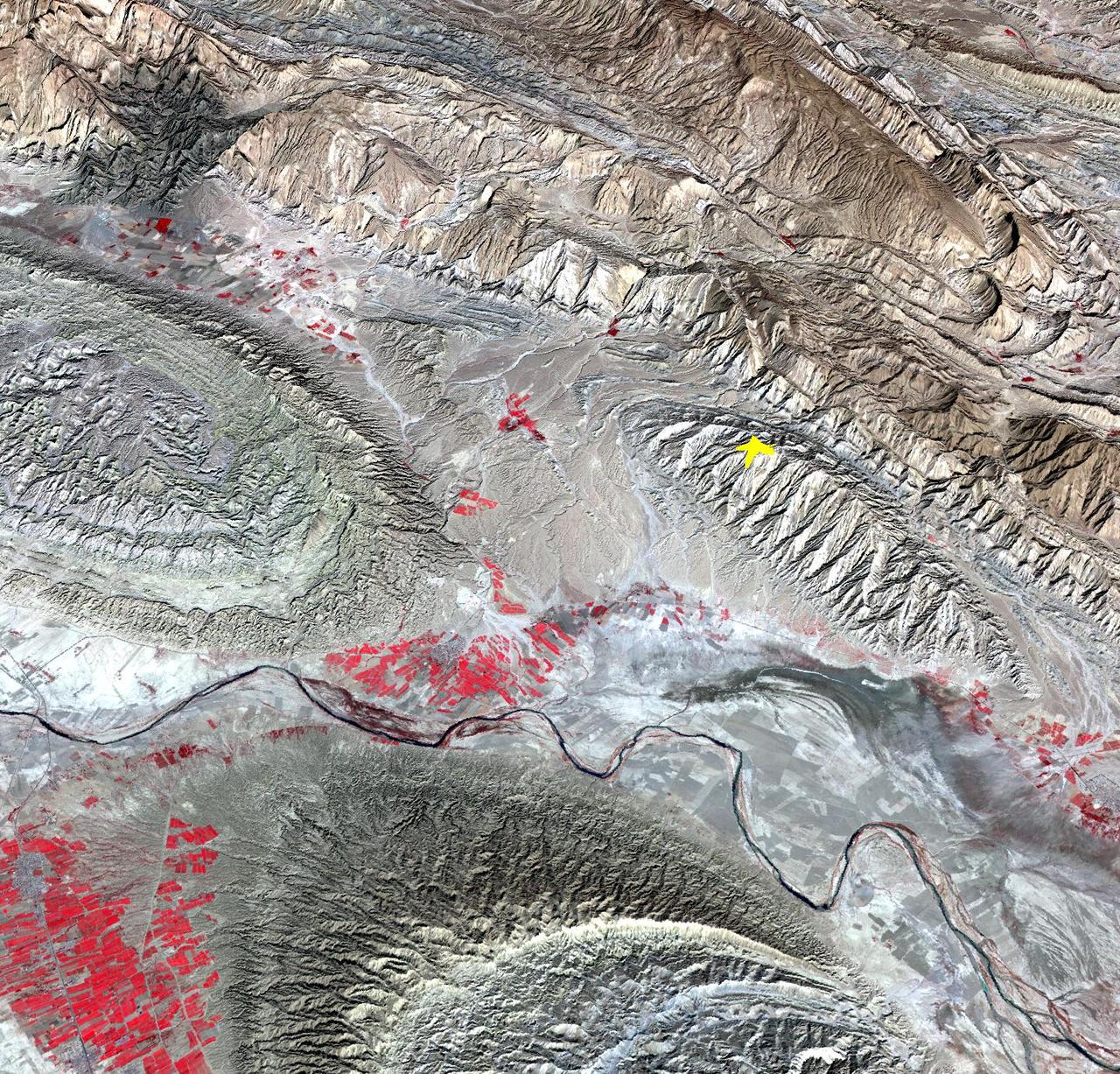
On April 9, 2013 at 11:52 GMT, a magnitude 6.3 earthquake hit southwestern Iran's Bushehr province near the town of Kaki. Preliminary information is that several villages have been destroyed and many people have died, as reported by BBC News. This perspective view of the region was acquired Nov. 17, 2012, by the Advanced Spaceborne Thermal Emission and Reflection Radiometer (ASTER) instrument on NASA's Terra spacecraft. The location of the earthquake's epicenter is marked with a yellow star. Vegetation is displayed in red; the vertical exaggeration of the topography is 2X. The image is centered near 28.5 degrees north latitude, 51.6 degrees east longitude. With its 14 spectral bands from the visible to the thermal infrared wavelength region and its high spatial resolution of 15 to 90 meters (about 50 to 300 feet), ASTER images Earth to map and monitor the changing surface of our planet. ASTER is one of five Earth-observing instruments launched Dec. 18, 1999, on Terra. The instrument was built by Japan's Ministry of Economy, Trade and Industry. A joint U.S./Japan science team is responsible for validation and calibration of the instrument and data products. The broad spectral coverage and high spectral resolution of ASTER provides scientists in numerous disciplines with critical information for surface mapping and monitoring of dynamic conditions and temporal change. Example applications are: monitoring glacial advances and retreats; monitoring potentially active volcanoes; identifying crop stress; determining cloud morphology and physical properties; wetlands evaluation; thermal pollution monitoring; coral reef degradation; surface temperature mapping of soils and geology; and measuring surface heat balance. The U.S. science team is located at NASA's Jet Propulsion Laboratory, Pasadena, Calif. The Terra mission is part of NASA's Science Mission Directorate, Washington, D.C. More information about ASTER is available at <a href="http://asterweb.jpl.nasa.gov/" rel="nofollow">asterweb.jpl.nasa.gov/</a>. Image Credit: NASA/GSFC/METI/ERSDAC/JAROS, and U.S./Japan ASTER Science Team Image Addition Date: 2013-04-10 <b><a href="http://www.nasa.gov/audience/formedia/features/MP_Photo_Guidelines.html" rel="nofollow">NASA image use policy.</a></b> <b><a href="http://www.nasa.gov/centers/goddard/home/index.html" rel="nofollow">NASA Goddard Space Flight Center</a></b> enables NASA’s mission through four scientific endeavors: Earth Science, Heliophysics, Solar System Exploration, and Astrophysics. Goddard plays a leading role in NASA’s accomplishments by contributing compelling scientific knowledge to advance the Agency’s mission. <b>Follow us on <a href="http://twitter.com/NASA_GoddardPix" rel="nofollow">Twitter</a></b> <b>Like us on <a href="http://www.facebook.com/pages/Greenbelt-MD/NASA-Goddard/395013845897?ref=tsd" rel="nofollow">Facebook</a></b> <b>Find us on <a href="http://instagram.com/nasagoddard?vm=grid" rel="nofollow">Instagram</a></b>

Salt Lake City, Utah, Winter 2001 The 2002 Winter Olympics are hosted by Salt Lake City at several venues within the city, in nearby cities, and within the adjacent Wasatch Mountains. This simulated natural color image presents a snowy, winter view of north central Utah that includes all of the Olympic sites. The image extends from Ogden in the north, to Provo in the south; and includes the snow-capped Wasatch Mountains and the eastern part of the Great Salt Lake. This image was acquired on February 8, 2001 by the Advanced Spaceborne Thermal Emission and Reflection Radiometer (ASTER) on NASA's Terra satellite. With its 14 spectral bands from the visible to the thermal infrared wavelength region, and its high spatial resolution of 15 to 90 meters (about 50 to 300 feet), ASTER will image Earth for the next 6 years to map and monitor the changing surface of our planet. ASTER is one of five Earth-observing instruments launched December 18,1999, on NASA's Terra satellite. The instrument was built by Japan's Ministry of Economy, Trade and Industry. A joint U.S./Japan science team is responsible for validation and calibration of the instrument and the data products. Dr. Anne Kahle at NASA's Jet Propulsion Laboratory, Pasadena, California, is the U.S. Science team leader; Bjorn Eng of JPL is the project manager. ASTER is the only high resolution imaging sensor on Terra. The Terra mission is part of NASA's Earth Science Enterprise, along-term research and technology program designed to examine Earth's land, oceans, atmosphere, ice and life as a total integrated system. The broad spectral coverage and high spectral resolution of ASTER will provide scientists in numerous disciplines with critical information for surface mapping, and monitoring dynamic conditions and temporal change. Example applications are: monitoring glacial advances and retreats; monitoring potentially active volcanoes; identifying crop stress; determining cloud morphology and physical properties; wetlands evaluation; thermal pollution monitoring; coral reef degradation; surface temperature mapping of soils and geology; and measuring surface heat balance. Image credit: NASA/GSFC/METI/ERSDAC/JAROS, and U.S./Japan ASTER Science Team Credit: <b><a href="http://www.earthobservatory.nasa.gov/" rel="nofollow"> NASA Earth Observatory</a></b> <b><a href="http://www.nasa.gov/audience/formedia/features/MP_Photo_Guidelines.html" rel="nofollow">NASA image use policy.</a></b> <b><a href="http://www.nasa.gov/centers/goddard/home/index.html" rel="nofollow">NASA Goddard Space Flight Center</a></b> enables NASA’s mission through four scientific endeavors: Earth Science, Heliophysics, Solar System Exploration, and Astrophysics. Goddard plays a leading role in NASA’s accomplishments by contributing compelling scientific knowledge to advance the Agency’s mission. <b>Follow us on <a href="http://twitter.com/NASAGoddardPix" rel="nofollow">Twitter</a></b> <b>Like us on <a href="http://www.facebook.com/pages/Greenbelt-MD/NASA-Goddard/395013845897?ref=tsd" rel="nofollow">Facebook</a></b> <b>Find us on <a href="http://instagram.com/nasagoddard?vm=grid" rel="nofollow">Instagram</a></b>
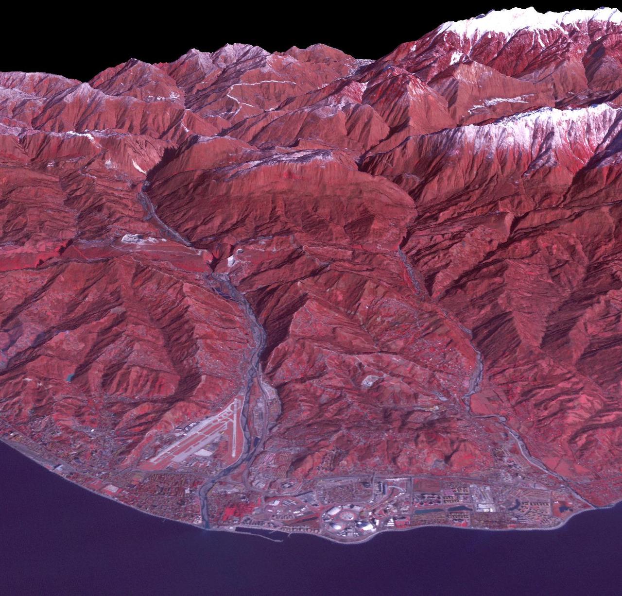
Sochi, Russia Winter Olympic Sites (Coastal Cluster) The Black Sea resort of Sochi, Russia, is the warmest city ever to host the Winter Olympic Games, which open on Feb. 7, 2014, and run through Feb. 23. This north-looking image, acquired on Jan. 4, 2014, by the Advanced Spaceborne Thermal Emission and Reflection Radiometer (ASTER) instrument on NASA's Terra spacecraft, shows the Sochi Olympic Park Coastal Cluster -- the circular area on the shoreline in the bottom center of the image -- which was built for Olympic indoor sports. Even curling has its own arena alongside multiple arenas for hockey and skating. The Olympic alpine events will take place at the Mountain Cluster, located in a snow-capped valley at the top right of the image. Sochi itself, a city of about 400,000, is not visible in the picture. It's farther west (left) along the coast, past the airport at bottom left. In the image, red indicates vegetation, white is snow, buildings are gray and the ocean is dark blue. The area imaged is about 15 miles (24 kilometers) from west to east (left to right) at the coastline and 25 miles (41 kilometers) from front to back. Height is exaggerated 1.5 times. The image was created from the ASTER visible and near-infrared bands, draped over ASTER-derived digital elevation data. With its 14 spectral bands from the visible to the thermal infrared wavelength region and its high spatial resolution of 15 to 90 meters (about 50 to 300 feet), ASTER images Earth to map and monitor the changing surface of our planet. ASTER is one of five Earth-observing instruments launched Dec. 18, 1999, on Terra. The instrument was built by Japan's Ministry of Economy, Trade and Industry. A joint U.S./Japan science team is responsible for validation and calibration of the instrument and data products. The broad spectral coverage and high spectral resolution of ASTER provides scientists in numerous disciplines with critical information for surface mapping and monitoring of dynamic conditions and temporal change. Example applications are: monitoring glacial advances and retreats; monitoring potentially active volcanoes; identifying crop stress; determining cloud morphology and physical properties; wetlands evaluation; thermal pollution monitoring; coral reef degradation; surface temperature mapping of soils and geology; and measuring surface heat balance. The U.S. science team is located at NASA's Jet Propulsion Laboratory, Pasadena, Calif. The Terra mission is part of NASA's Science Mission Directorate, Washington, D.C. More information about ASTER is available at <a href="http://asterweb.jpl.nasa.gov/" rel="nofollow">asterweb.jpl.nasa.gov/</a>. Image credit: NASA/GSFC/METI/ERSDAC/JAROS, and U.S./Japan ASTER Science Team <b><a href="http://www.nasa.gov/audience/formedia/features/MP_Photo_Guidelines.html" rel="nofollow">NASA image use policy.</a></b> <b><a href="http://www.nasa.gov/centers/goddard/home/index.html" rel="nofollow">NASA Goddard Space Flight Center</a></b> enables NASA’s mission through four scientific endeavors: Earth Science, Heliophysics, Solar System Exploration, and Astrophysics. Goddard plays a leading role in NASA’s accomplishments by contributing compelling scientific knowledge to advance the Agency’s mission. <b>Follow us on <a href="http://twitter.com/NASAGoddardPix" rel="nofollow">Twitter</a></b> <b>Like us on <a href="http://www.facebook.com/pages/Greenbelt-MD/NASA-Goddard/395013845897?ref=tsd" rel="nofollow">Facebook</a></b> <b>Find us on <a href="http://instagram.com/nasagoddard?vm=grid" rel="nofollow">Instagram</a></b>

Sochi, Russia Winter Olympic Sites (Mountain Cluster) The 2014 Winter Olympic ski runs may be rated double black diamond, but they're not quite as steep as they appear in this image of the skiing and snowboarding sites for the Sochi Winter Olympic Games, acquired on Jan. 4, 2014, by the Advanced Spaceborne Thermal Emission and Reflection Radiometer (ASTER) instrument on NASA's Terra spacecraft. Rosa Khutar ski resort near Sochi, Russia, is in the valley at center, and the runs are visible on the shadowed slopes on the left-hand side of the valley. Height has been exaggerated 1.5 times to bring out topographic details. The games, which begin on Feb. 7 and continue for 17 days, feature six new skiing and boarding events plus the return of the legendary Jamaican bobsled team to the winter games for the first time since 2002. In this southwest-looking image, red indicates vegetation, white is snow, and the resort site appears in gray. The area imaged is about 11 miles (18 kilometers) across in the foreground and 20 miles (32 kilometers) from front to back. The image was created from the ASTER visible and near-infrared bands, draped over ASTER-derived digital elevation data. With its 14 spectral bands from the visible to the thermal infrared wavelength region and its high spatial resolution of 15 to 90 meters (about 50 to 300 feet), ASTER images Earth to map and monitor the changing surface of our planet. ASTER is one of five Earth-observing instruments launched Dec. 18, 1999, on Terra. The instrument was built by Japan's Ministry of Economy, Trade and Industry. A joint U.S./Japan science team is responsible for validation and calibration of the instrument and data products. The broad spectral coverage and high spectral resolution of ASTER provides scientists in numerous disciplines with critical information for surface mapping and monitoring of dynamic conditions and temporal change. Example applications are: monitoring glacial advances and retreats; monitoring potentially active volcanoes; identifying crop stress; determining cloud morphology and physical properties; wetlands evaluation; thermal pollution monitoring; coral reef degradation; surface temperature mapping of soils and geology; and measuring surface heat balance. The U.S. science team is located at NASA's Jet Propulsion Laboratory, Pasadena, Calif. The Terra mission is part of NASA's Science Mission Directorate, Washington, D.C. More information about ASTER is available at <a href="http://asterweb.jpl.nasa.gov/" rel="nofollow">asterweb.jpl.nasa.gov/</a>. credit:NASA/GSFC/METI/ERSDAC/JAROS, and U.S./Japan ASTER Science Team <b><a href="http://www.nasa.gov/audience/formedia/features/MP_Photo_Guidelines.html" rel="nofollow">NASA image use policy.</a></b> <b><a href="http://www.nasa.gov/centers/goddard/home/index.html" rel="nofollow">NASA Goddard Space Flight Center</a></b> enables NASA’s mission through four scientific endeavors: Earth Science, Heliophysics, Solar System Exploration, and Astrophysics. Goddard plays a leading role in NASA’s accomplishments by contributing compelling scientific knowledge to advance the Agency’s mission. <b>Follow us on <a href="http://twitter.com/NASAGoddardPix" rel="nofollow">Twitter</a></b> <b>Like us on <a href="http://www.facebook.com/pages/Greenbelt-MD/NASA-Goddard/395013845897?ref=tsd" rel="nofollow">Facebook</a></b> <b>Find us on <a href="http://instagram.com/nasagoddard?vm=grid" rel="nofollow">Instagram</a></b>
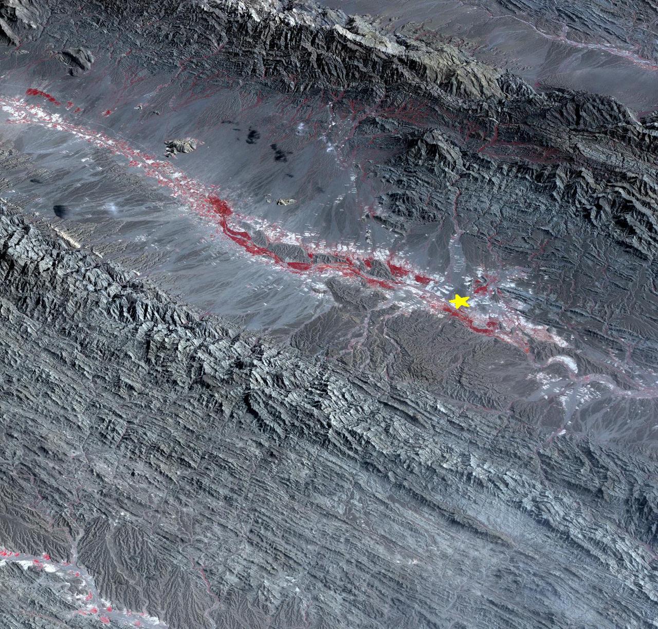
On September 24 at 11:29 GMT, a magnitude 7.7 earthquake struck in south-central Pakistan at a relatively shallow depth of 20 kilometers. The earthquake occurred as the result of oblique strike-slip motion, consistent with rupture within the Eurasian tectonic plate. Tremors were felt as far away as New Delhi as well as Karachi in Pakistan. Even though the immediate area to the epicenter is sparsely populated, the majority of houses are of mud brick construction and damage is expected to be extensive. The perspective view, looking to the east, shows the location of the epicenter in Pakistan's Makran fold belt. The image is centered near 27 degrees north latitude, 65.5 degrees east longitude, and was acquired December 13, 2012. With its 14 spectral bands from the visible to the thermal infrared wavelength region and its high spatial resolution of 15 to 90 meters (about 50 to 300 feet), ASTER images Earth to map and monitor the changing surface of our planet. ASTER is one of five Earth-observing instruments launched Dec. 18, 1999, on Terra. The instrument was built by Japan's Ministry of Economy, Trade and Industry. A joint U.S./Japan science team is responsible for validation and calibration of the instrument and data products. The broad spectral coverage and high spectral resolution of ASTER provides scientists in numerous disciplines with critical information for surface mapping and monitoring of dynamic conditions and temporal change. Example applications are: monitoring glacial advances and retreats; monitoring potentially active volcanoes; identifying crop stress; determining cloud morphology and physical properties; wetlands evaluation; thermal pollution monitoring; coral reef degradation; surface temperature mapping of soils and geology; and measuring surface heat balance. The U.S. science team is located at NASA's Jet Propulsion Laboratory, Pasadena, Calif. The Terra mission is part of NASA's Science Mission Directorate, Washington, D.C. More information about ASTER is available at <a href="http://asterweb.jpl.nasa.gov/" rel="nofollow">asterweb.jpl.nasa.gov/</a>. Image Credit: NASA/GSFC/METI/ERSDAC/JAROS, and U.S./Japan ASTER Science Team Image Addition Date: 2013-09-24 <b><a href="http://www.nasa.gov/audience/formedia/features/MP_Photo_Guidelines.html" rel="nofollow">NASA image use policy.</a></b> <b><a href="http://www.nasa.gov/centers/goddard/home/index.html" rel="nofollow">NASA Goddard Space Flight Center</a></b> enables NASA’s mission through four scientific endeavors: Earth Science, Heliophysics, Solar System Exploration, and Astrophysics. Goddard plays a leading role in NASA’s accomplishments by contributing compelling scientific knowledge to advance the Agency’s mission. <b>Follow us on <a href="http://twitter.com/NASA_GoddardPix" rel="nofollow">Twitter</a></b> <b>Like us on <a href="http://www.facebook.com/pages/Greenbelt-MD/NASA-Goddard/395013845897?ref=tsd" rel="nofollow">Facebook</a></b> <b>Find us on <a href="http://instagram.com/nasagoddard?vm=grid" rel="nofollow">Instagram</a></b>
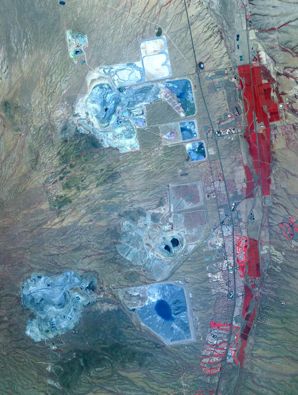
Arizona produces 60% of the total copper mined in the US; in 2007, 750,000 tons of copper came out of the state. One of the major mining districts is located about 30 km south of Tucson. Starting around 1950, open-pit mining replaced underground operations, and the ASARCO-Mission complex, Twin Buttes, and Sierrita mines became large open pit operations. Accompanying copper mineralization, silver, molybdenum, zinc, lead and gold are extracted. In addition to the pits themselves, enormous leach ponds and tailings piles surround the pits. The image was acquired May 31, 2012, covers an area of 22 by 28 km, and is located at 31.9 degrees north, 111 degrees west. With its 14 spectral bands from the visible to the thermal infrared wavelength region and its high spatial resolution of 15 to 90 meters (about 50 to 300 feet), ASTER images Earth to map and monitor the changing surface of our planet. ASTER is one of five Earth-observing instruments launched Dec. 18, 1999, on Terra. The instrument was built by Japan's Ministry of Economy, Trade and Industry. A joint U.S./Japan science team is responsible for validation and calibration of the instrument and data products. The broad spectral coverage and high spectral resolution of ASTER provides scientists in numerous disciplines with critical information for surface mapping and monitoring of dynamic conditions and temporal change. Example applications are: monitoring glacial advances and retreats; monitoring potentially active volcanoes; identifying crop stress; determining cloud morphology and physical properties; wetlands evaluation; thermal pollution monitoring; coral reef degradation; surface temperature mapping of soils and geology; and measuring surface heat balance. The U.S. science team is located at NASA's Jet Propulsion Laboratory, Pasadena, Calif. The Terra mission is part of NASA's Science Mission Directorate, Washington, D.C. More information about ASTER is available at <a href="http://asterweb.jpl.nasa.gov/" rel="nofollow">asterweb.jpl.nasa.gov/</a> Credit: NASA/GSFC/METI/ERSDAC/JAROS, and U.S./Japan ASTER Science Team <b><a href="http://www.nasa.gov/audience/formedia/features/MP_Photo_Guidelines.html" rel="nofollow">NASA image use policy.</a></b> <b><a href="http://www.nasa.gov/centers/goddard/home/index.html" rel="nofollow">NASA Goddard Space Flight Center</a></b> enables NASA’s mission through four scientific endeavors: Earth Science, Heliophysics, Solar System Exploration, and Astrophysics. Goddard plays a leading role in NASA’s accomplishments by contributing compelling scientific knowledge to advance the Agency’s mission. <b>Follow us on <a href="http://twitter.com/NASAGoddardPix" rel="nofollow">Twitter</a></b> <b>Like us on <a href="http://www.facebook.com/pages/Greenbelt-MD/NASA-Goddard/395013845897?ref=tsd" rel="nofollow">Facebook</a></b> <b>Find us on <a href="http://instagram.com/nasagoddard?vm=grid" rel="nofollow">Instagram</a></b>