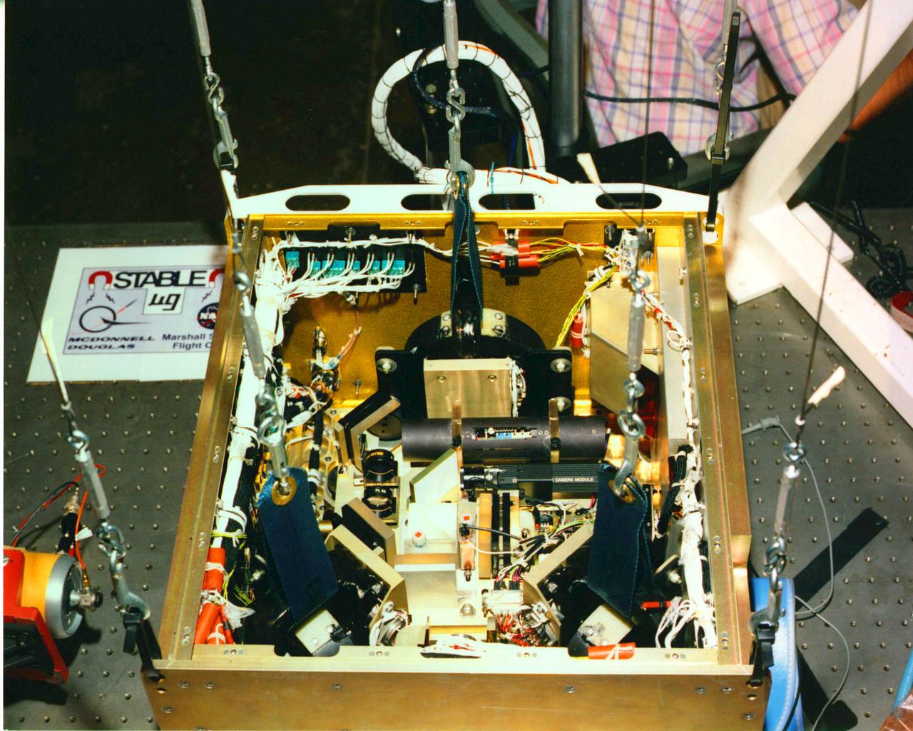
(STABLE) Suppression of Transient Accelerations by Leviation Evaluation
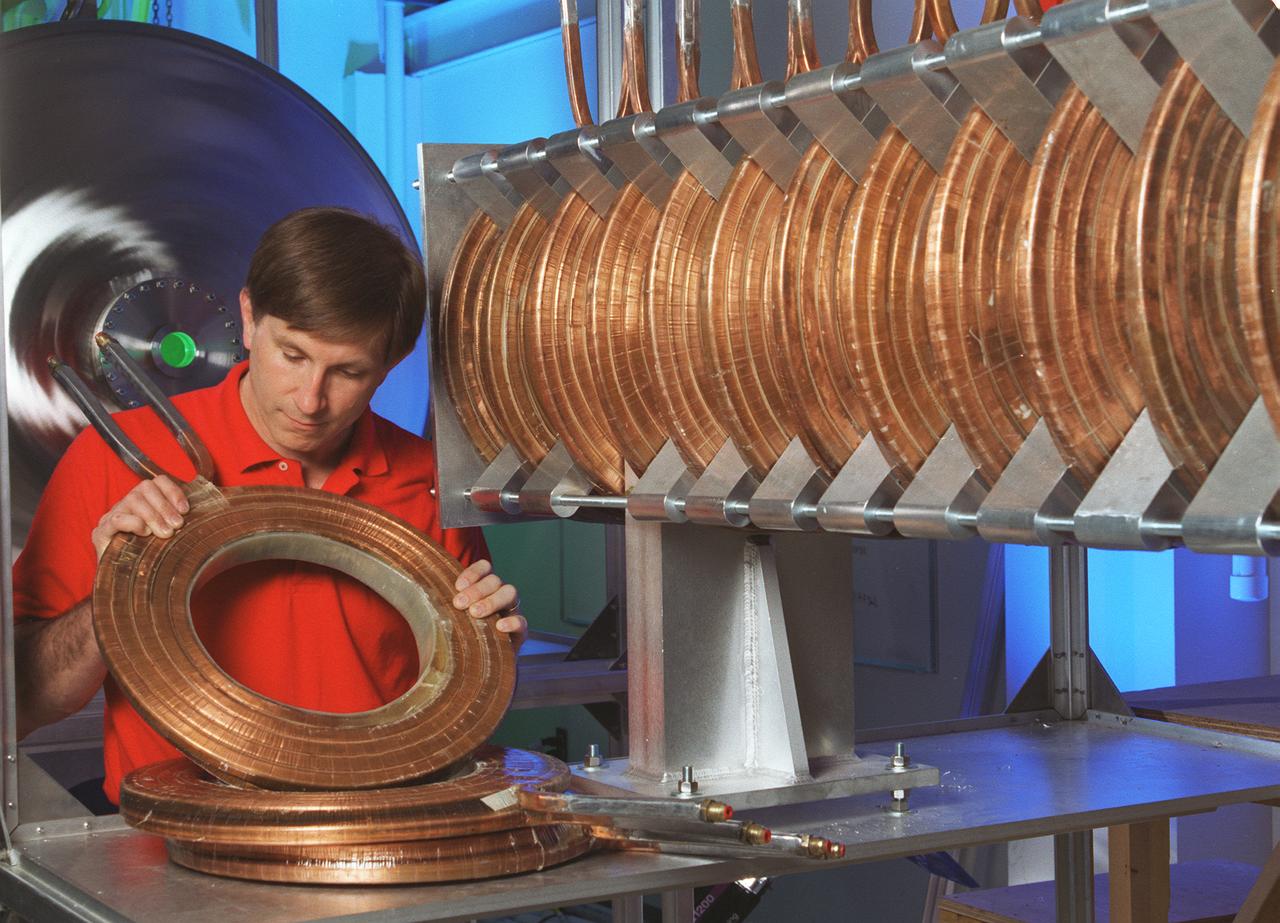
The Gasdynamic Mirror, or GDM, is an example of a magnetic mirror-based fusion propulsion system. Its design is primarily consisting of a long slender solenoid surrounding a vacuum chamber that contains plasma. The bulk of the fusion plasma is confined by magnetic field generated by a series of toroidal-shaped magnets in the center section of the device. the purpose of the GDM Fusion Propulsion Experiment is to confirm the feasibility of the concept and to demonstrate many of the operational characteristics of a full-size plasma can be confined within the desired physical configuration and still reman stable. This image shows an engineer from Propulsion Research Technologies Division at Marshall Space Flight Center inspecting solenoid magnets-A, an integrate part of the Gasdynamic Mirror Fusion Propulsion Engine Experiment.
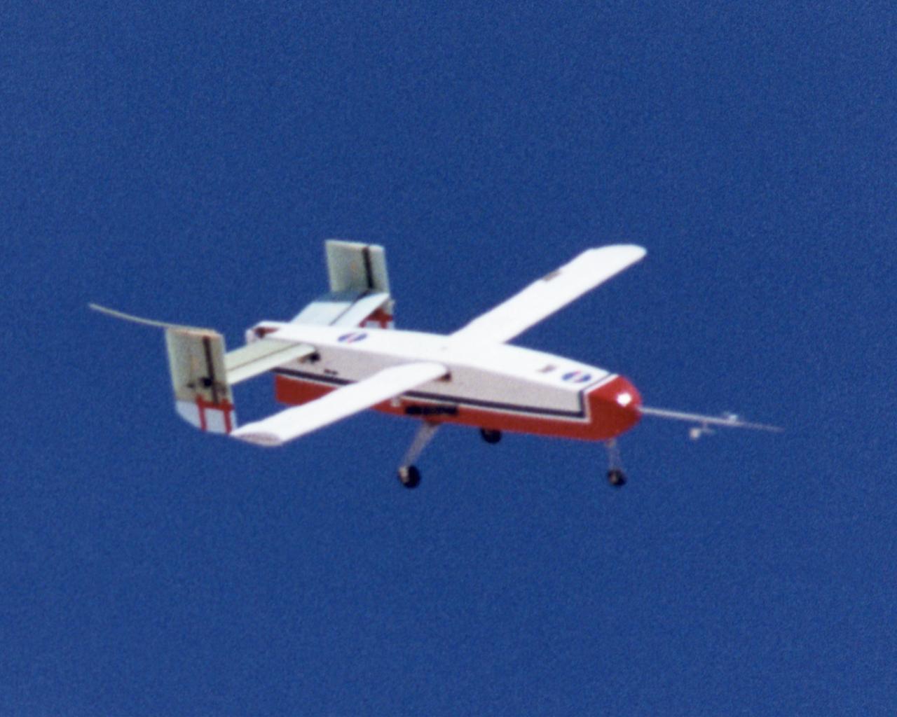
Wing Deployment Sequence #3: The deployable, inflatable wing technology demonstrator experiment aircraft's wings fully deployed during flight following separation from its carrier aircraft during a flight conducted by the NASA Dryden Flight Research Center, Edwards, Californiaornia. The inflatable wing project represented a basic flight research effort by Dryden personnel. Three successful flights of the I2000 inflatable wing aircraft occurred. During the flights, the team air-launched the radio-controlled (R/C) I2000 from an R/C utility airplane at an altitude of 800-1000 feet. As the I2000 separated from the carrier aircraft, its inflatable wings "popped-out," deploying rapidly via an on-board nitrogen bottle. The aircraft remained stable as it transitioned from wingless to winged flight. The unpowered I2000 glided down to a smooth landing under complete control.
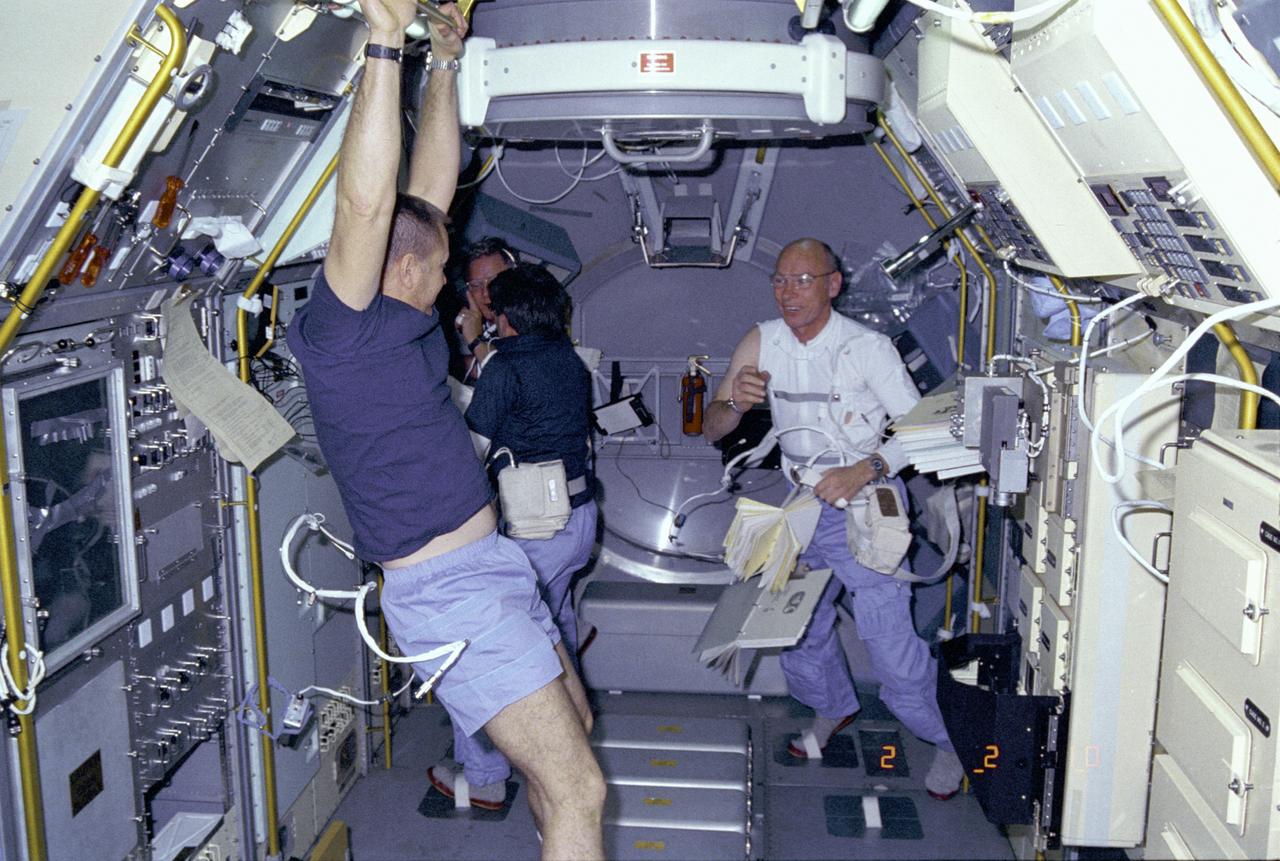
Activities inside the laboratory module during the Spacelab-3 mission are shown in this photograph. Left to right are astronauts Robert Overmyer, Commander of the mission; Don Lind, Mission Specialist; Lodewijk van den Berg, Payload Specialist; and William Thornton, Mission Specialist. The primary purpose of the Spacelab-3 mission was to conduct materials science experiments in a stable low-gravity environment. In addition, the crew did research in life sciences, fluid mechanics, atmospheric science, and astronomy. Spacelab-3 was equipped with several new minilabs, special facilities that would be used repeatedly on future flights. Two elaborate crystal growth furnaces, a life support and housing facility for small animals, and two types of apparatus for the study of fluids were evaluated on their inaugural flight. Spacelab-3 (STS-51B) was launched aboard the Space Shuttle Challenger on April 29, 1985. The Marshall Space Flight Center had managing responsibilities of the mission.
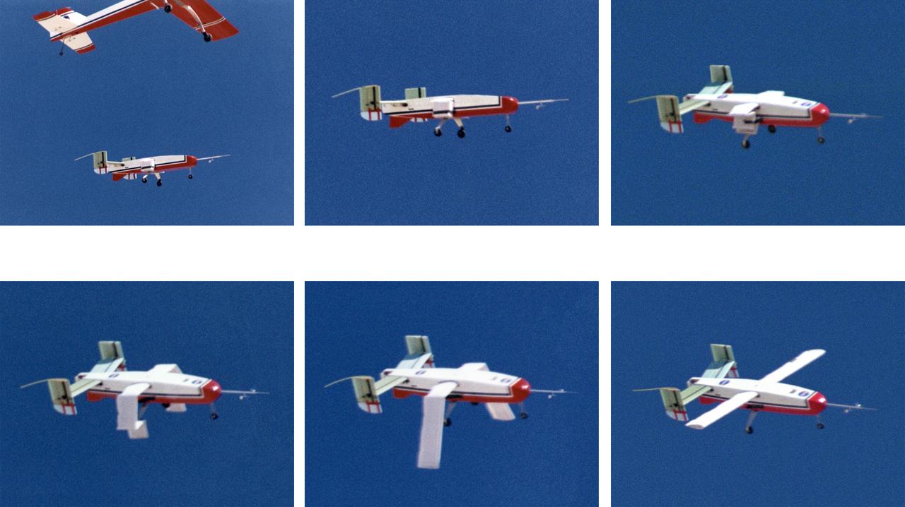
The deployable, inflatable wing technology demonstrator aircraft's wings begin deploying following separation from its carrier aircraft during a flight experiment conducted by the NASA Dryden Flight Research Center, Edwards, California. Wing deployment time is typically on the order of a third of a second, almost faster than the human eye can see. Three successful flights of the I2000 inflatable wing aircraft occurred. During the flights, the team air-launched the radio-controlled (R/C) I2000 from an R/C utility airplane at an altitude of 800-1000 feet. As the I2000 separated from the carrier aircraft, its inflatable wings "popped-out," deploying rapidly via an on-board nitrogen bottle. The aircraft remained stable as it transitioned from wingless to winged flight. The unpowered I2000 glided down to a smooth landing under complete control.
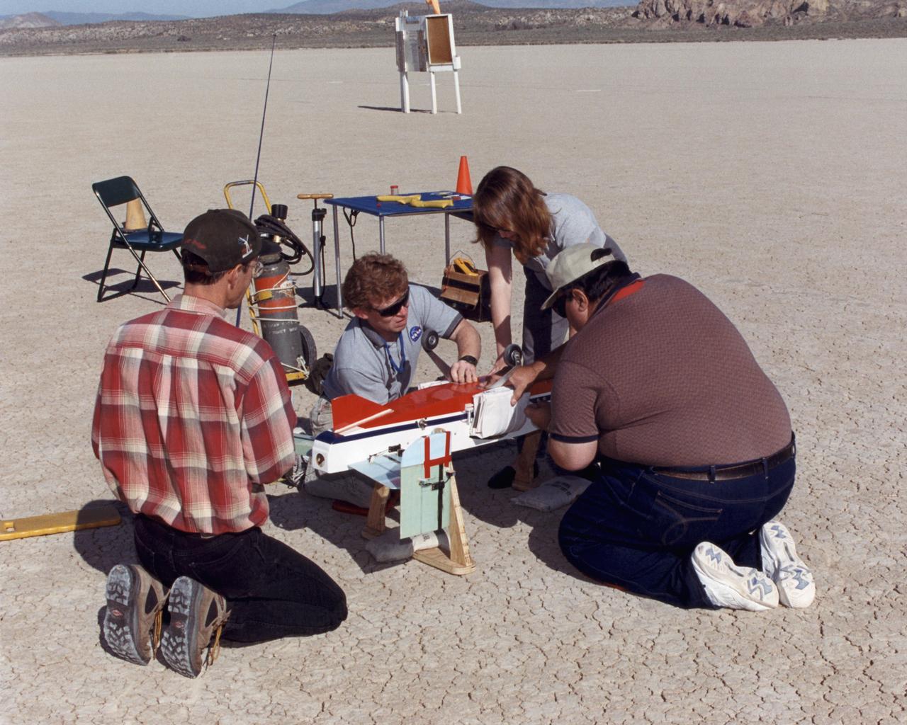
Inflatable Wing project personnel prepare a deployable, inflatable wing technology demonstrator experiment flown by the NASA Dryden Flight Research Center, Edwards, California. The inflatable wing project represented a basic flight research effort by Dryden personnel. Three successful flights of the I2000 inflatable wing aircraft occurred. During the flights, the team air-launched the radio-controlled (R/C) I2000 from an R/C utility airplane at an altitude of 800-1000 feet. As the I2000 separated from the carrier aircraft, its inflatable wings "popped-out," deploying rapidly via an on-board nitrogen bottle. The aircraft remained stable as it transitioned from wingless to winged flight. The unpowered I2000 glided down to a smooth landing under complete control.
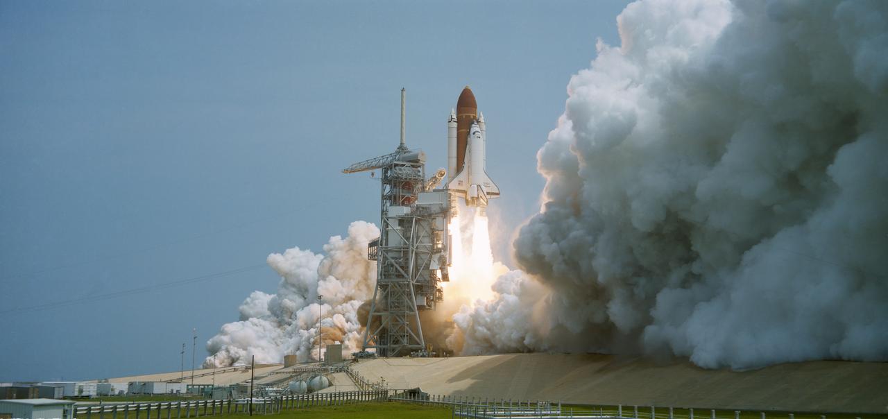
51B-S-052 (20 April 1985) --- The STS 51-B Spacelab 3 mission begins with the liftoff of the Challenger from Pad 39A at 12:02 p.m. (EDT). The Spacelab-3 configuration consists of a long module and a Mission Experiment Support Structure (MPESS). The object of the mission is to conduct applications, science and technology-oriented experimentation requiring the low-gravity of Earth orbit and extended duration stable vehicle attitude. Mission emphasis will be on materials processing. The seven-member crew consists of astronauts Robert F Overmyer, commander; Frederick D. Gregory, pilot; Don L. Lind, Norman E. Thagard and William E. Thornton; all mission specialists and payload specialists Taylor G. Wang and Lodewijk van den Berg. The mission is planned for 7 days with a landing at Dryden Flight Research Facility, Edwards California scheduled for May 6.
Wing Deployment Sequence #2: The deployable, inflatable wing technology demonstrator experiment aircraft's wings continue deploying following separation from its carrier aircraft during a flight conducted by the NASA Dryden Flight Research Center, Edwards, California. The inflatable wing project represented a basic flight research effort by Dryden personnel. Three successful flights of the I2000 inflatable wing aircraft occurred. During the flights, the team air-launched the radio-controlled (R/C) I2000 from an R/C utility airplane at an altitude of 800-1000 feet. As the I2000 separated from the carrier aircraft, its inflatable wings "popped-out," deploying rapidly via an on-board nitrogen bottle. The aircraft remained stable as it transitioned from wingless to winged flight. The unpowered I2000 glided down to a smooth landing under complete control.
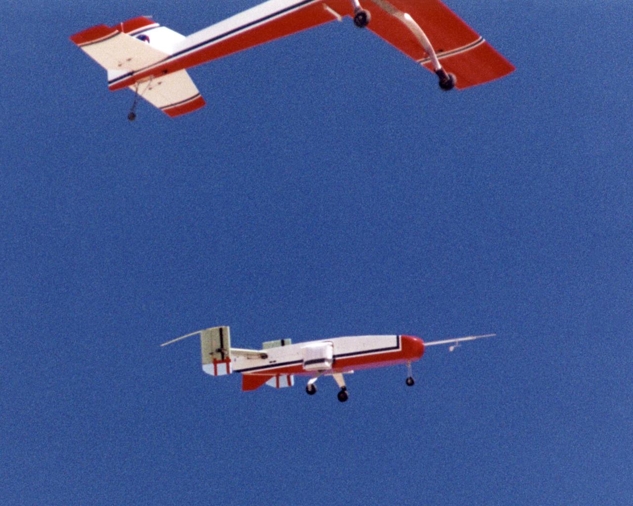
The deployable, inflatable wing technology demonstrator experiment separates from its carrier aircraft during a flight conducted by the NASA Dryden Flight Research Center, Edwards, California. The inflatable wing project represented a basic flight research effort by Dryden personnel. Three successful flights of the I2000 inflatable wing aircraft occurred. During the flights, the team air-launched the radio-controlled (R/C) I2000 from an R/C utility airplane at an altitude of 800-1000 feet. As the I2000 separated from the carrier aircraft, its inflatable wings "popped-out," deploying rapidly via an on-board nitrogen bottle. The aircraft remained stable as it transitioned from wingless to winged flight. The unpowered I2000 glided down to a smooth landing under complete control.
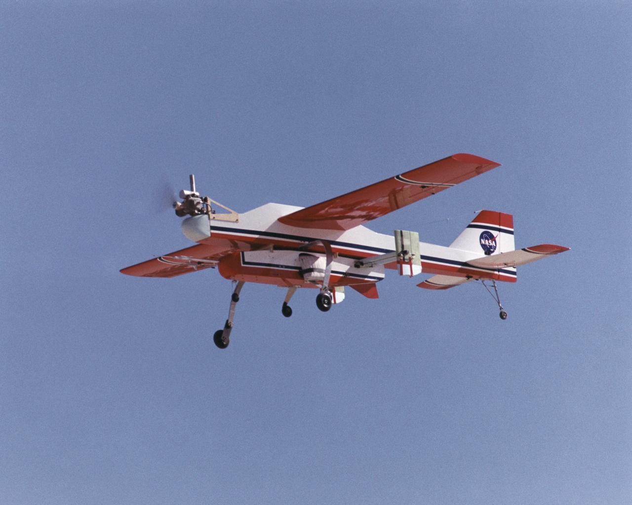
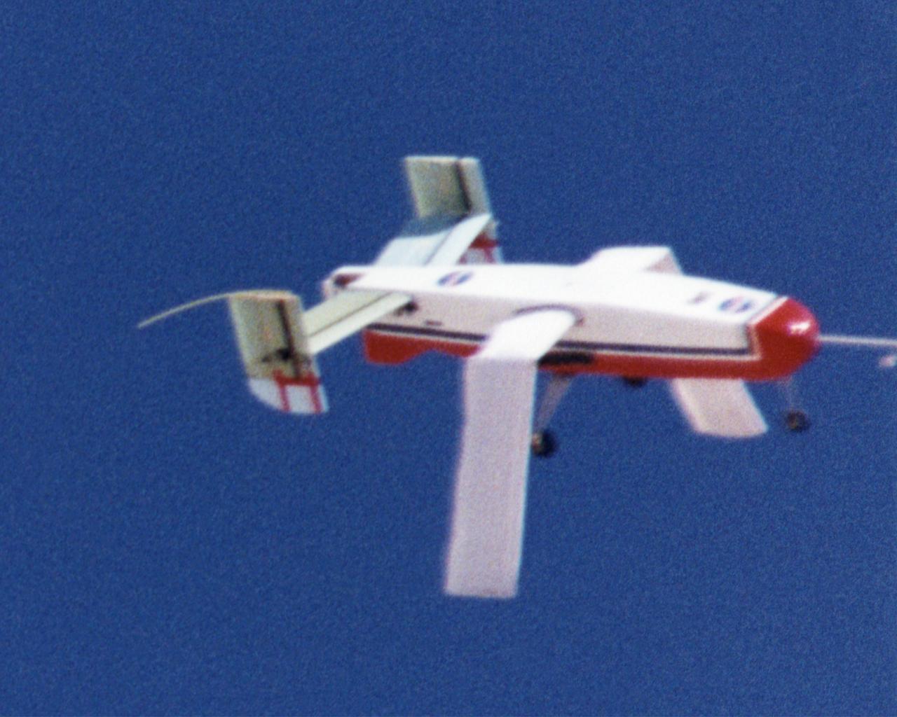
The deployable, inflatable wing technology demonstrator experiment aircraft looks good during a flight conducted by the NASA Dryden Flight Research Center, Edwards, California. The inflatable wing project represented a basic flight research effort by Dryden personnel. Three successful flights of the I2000 inflatable wing aircraft occurred. During the flights, the team air-launched the radio-controlled (R/C) I2000 from an R/C utility airplane at an altitude of 800-1000 feet. As the I2000 separated from the carrier aircraft, its inflatable wings "popped-out," deploying rapidly via an on-board nitrogen bottle. The aircraft remained stable as it transitioned from wingless to winged flight. The unpowered I2000 glided down to a smooth landing under complete control.
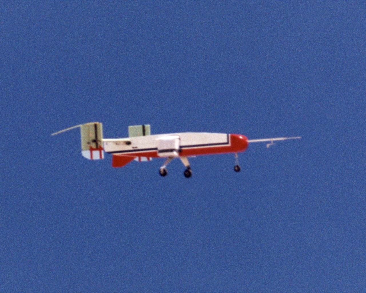
The deployable, inflatable wing technology demonstrator experiment aircraft maintains a steady attitude following separation from its carrier aircraft during a flight conducted by the NASA Dryden Flight Research Center, Edwards, California. The inflatable wing project represented a basic flight research effort by Dryden personnel. Three successful flights of the I2000 inflatable wing aircraft occurred. During the flights, the team air-launched the radio-controlled (R/C) I2000 from an R/C utility airplane at an altitude of 800-1000 feet. As the I2000 separated from the carrier aircraft, its inflatable wings "popped-out," deploying rapidly via an on-board nitrogen bottle. The aircraft remained stable as it transitioned from wingless to winged flight. The unpowered I2000 glided down to a smooth landing under complete control.
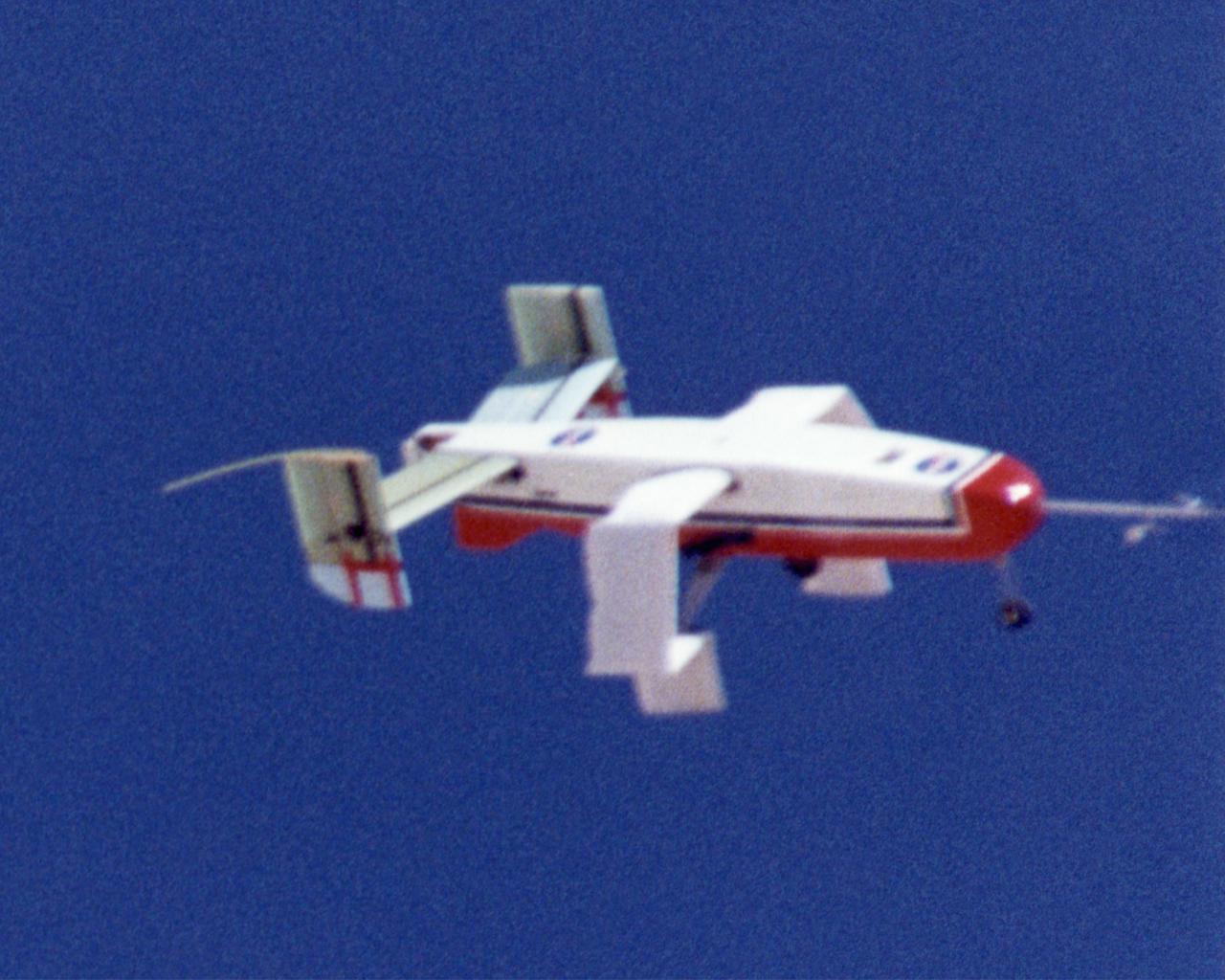
Wing Deployment Sequence #1: The deployable, inflatable wing technology demonstrator experiment aircraft's wings begin deploying following separation from its carrier aircraft during a flight conducted by the NASA Dryden Flight Research Center, Edwards, California. The inflatable wing project represented a basic flight research effort by Dryden personnel. Three successful flights of the I2000 inflatable wing aircraft occurred. During the flights, the team air-launched the radio-controlled (R/C) I2000 from an R/C utility airplane at an altitude of 800-1000 feet. As the I2000 separated from the carrier aircraft, its inflatable wings "popped-out," deploying rapidly via an on-board nitrogen bottle. The aircraft remained stable as it transitioned from wingless to winged flight. The unpowered I2000 glided down to a smooth landing under complete control.
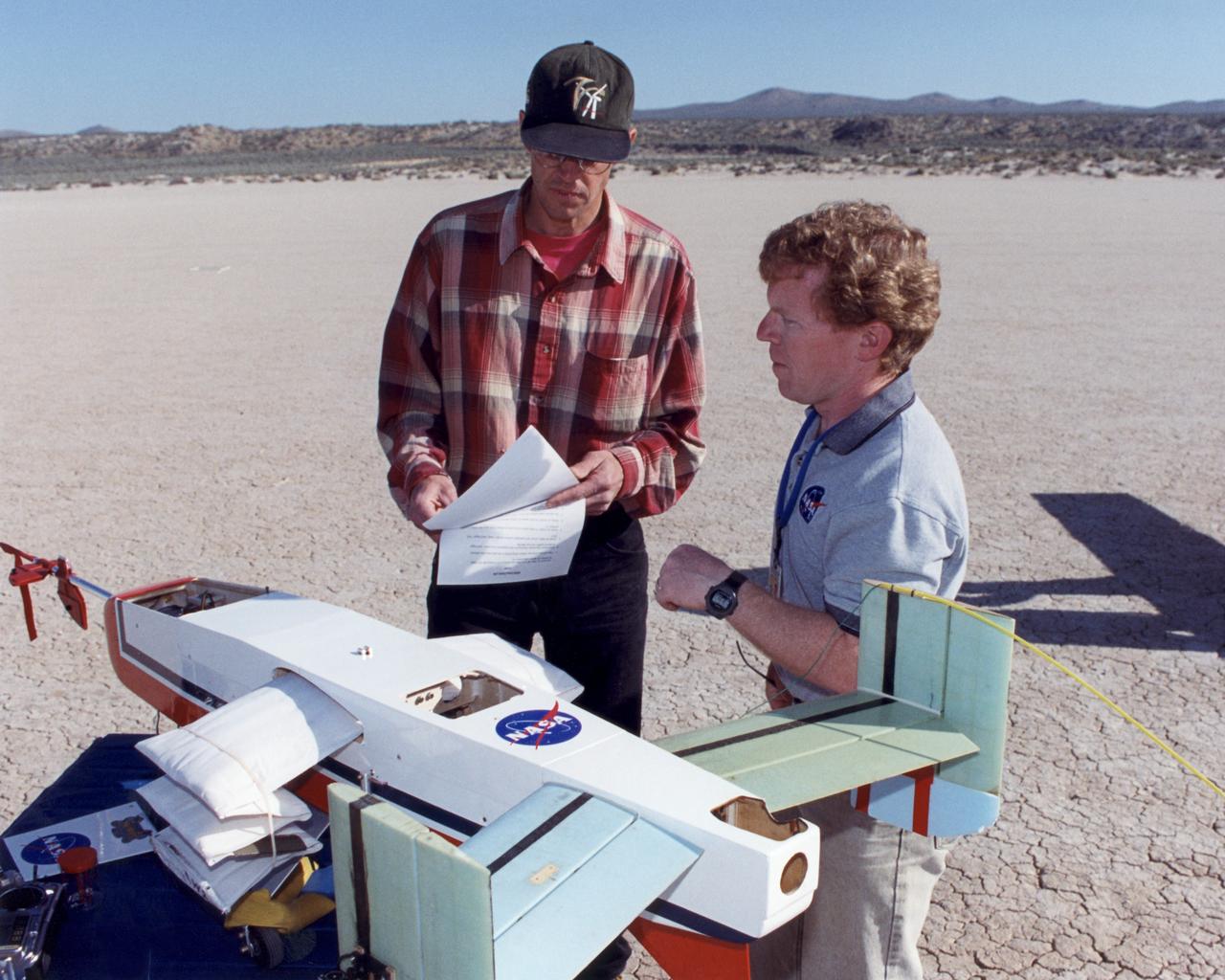
Engineers Jim Murray and Joe Pahle prepare a deployable, inflatable wing technology demonstrator experiment flown by the NASA Dryden Flight Research Center, Edwards, California. The inflatable wing project represented a basic flight research effort by Dryden personnel. Three successful flights of the I2000 inflatable wing aircraft occurred. During the flights, the team air-launched the radio-controlled (R/C) I2000 from an R/C utility airplane at an altitude of 800-1000 feet. As the I2000 separated from the carrier aircraft, its inflatable wings "popped-out," deploying rapidly via an on-board nitrogen bottle. The aircraft remained stable as it transitioned from wingless to winged flight. The unpowered I2000 glided down to a smooth landing under complete control.
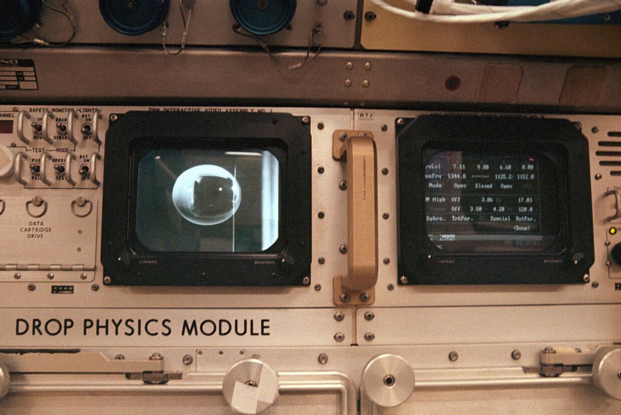
The first United States Microgravity Laboratory (USML-1) was one of NASA's science and technology programs that provided scientists an opportunity to research various scientific investigations in a weightlessness environment inside the Spacelab module. It also provided demonstrations of new equipment to help prepare for advanced microgravity research and processing aboard the Space Station. The USML-1 flew in orbit for extended periods, providing greater opportunities for research in materials science, fluid dynamics, biotechnology (crystal growth), and combustion science. This is a close-up view of the Drop Physics Module (DPM) in the USML science laboratory. The DPM was dedicated to the detailed study of the dynamics of fluid drops in microgravity: their equilibrium shapes, the dynamics of their flows, and their stable and chaotic behaviors. It also demonstrated a technique known as containerless processing. The DPM and microgravity combine to remove the effects of the container, such as chemical contamination and shape, on the sample being studied. Sound waves, generating acoustic forces, were used to suspend a sample in microgravity and to hold a sample of free drops away from the walls of the experiment chamber, which isolated the sample from potentially harmful external influences. The DPM gave scientists the opportunity to test theories of classical fluid physics, which have not been confirmed by experiments conducted on Earth. This image is a close-up view of the DPM. The USML-1 flew aboard the STS-50 mission on June 1992, and was managed by the Marshall Space Flight Center.
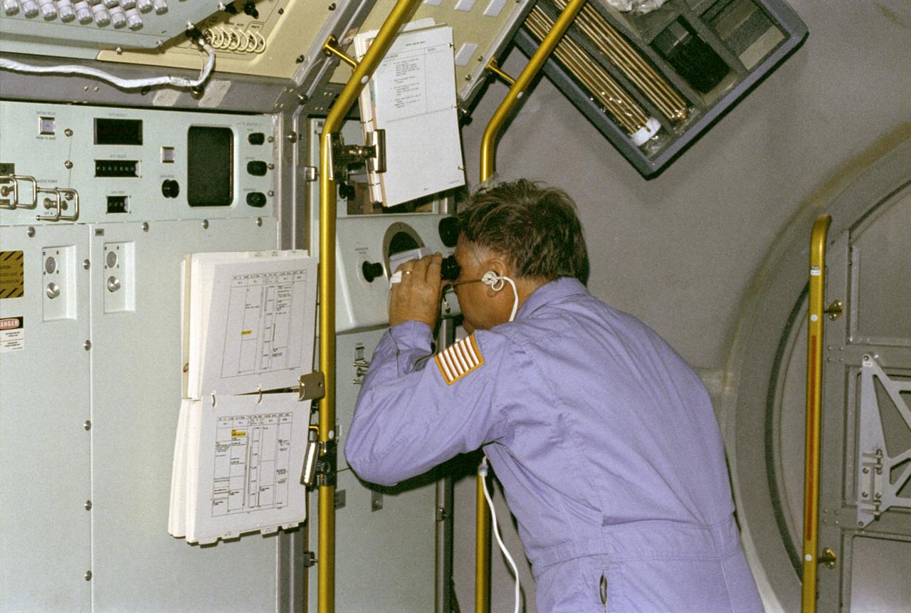
The primary purpose of the Spacelab-3 mission was to conduct materials science experiments in a stable low-gravity environment. In addition, the crew performed research in life sciences, fluid mechanics, atmospheric science, and astronomy. Spacelab-3 was equipped with several new minilabs, special facilities that would be used repeatedly on future flights. Two elaborate crystal growth furnaces, a life support and housing facility for small animals, and two types of apparatus for the study of fluids were evaluated on their inaugural flight. In this photograph, astronaut Don Lind observes the mercuric iodide growth experiment through a microscope at the vapor crystal growth furnace. The goals of this investigation were to grow near-perfect single crystals of mercuric iodide and to gain improved understanding of crystal growth by a vapor process. Mercuric iodide crystals have practical use as sensitive x-ray and gamma-ray detectors, and in portable detector devices for nuclear power plant monitoring, natural resource prospecting, biomedical applications in diagnosis and therapy, and in astronomical instruments. Managed by the Marshall Space Flight Center, Spacelab-3 (STS-51B) was launched aboard the Space Shuttle Orbiter Challenger on April 29, 1985.
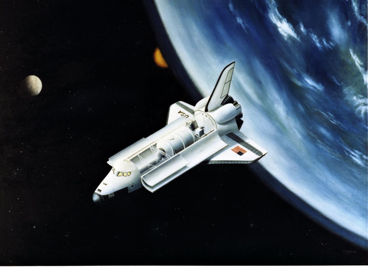
The primary purpose of the Spacelab-3 mission was to conduct materials science experiments in a stable low-gravity environment. In addition, the crew did research in life sciences, fluid mechanics, atmospheric science, and astronomy. Spacelab-3 was equipped with several new mini-labs, special facilities that would be used repeatedly on future flights. Two elaborate crystal growth furnaces, a life support and housing facility for small animals, and two types of apparatus for the study of fluids were evaluated on their inaugural flight. The instruments requiring direct exposure to space were mounted outside in the open payload bay of the Shuttle. Spacelab represented the merger of science and marned spaceflight. It opened remarkable opportunities to push the frontiers of knowledge beyond the limits of research on Earth. Scientists in space performed experiments in close collaboration with their colleagues on the ground. On the Spacelab-3 mission, managed by the Marshall Space Flight Center, this versatile laboratory entered routine operation service for the next two decades. Spacelab-3 (STS-51B mission) was launched aboard Space Shuttle Orbiter Challenger on April 29, 1985.
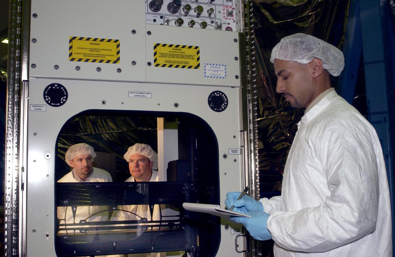
Developed by Boeing, at the Marshall Space Flight Center (MSFC) Space Station Manufacturing building, the Window Observational Rack Facility (WORF) will help Space Station crews take some of the best photographs ever snapped from an orbiting spacecraft by eliminating glare and allowing researchers to control their cameras and other equipment from the ground. The WORF is designed to make the best possible use of the high-quality research window in the Space Station's U.S. Destiny laboratory module. Engineers at the MSFC proposed a derivative of the EXPRESS (Expedite the Processing of Experiments to the Space Station) Rack already used on the Space Station and were given the go-ahead. The EXPRESS rack can hold a wide variety of experiments and provide them with power, communications, data, cooling, fluids, and other utilities - all the things that Earth-observing experiment instruments would need. WORF will supply payloads with power, data, cooling, video downlink, and stable, standardized interfaces for mounting imaging instruments. Similar to specialized orbital observatories, the interior of the rack is sealed against light and coated with a special low-reflectant black paint, so payloads will be able to observe low-light-level subjects such as the faint glow of auroras. Cameras and remote sensing instruments in the WORF can be preprogrammed, controlled from the ground, or operated by a Station crewmember by using a flexible shroud designed to cinch tightly around the crewmember's waist. The WORF is scheduled to be launched aboard the STS-114 Space Shuttle mission in the year 2003.
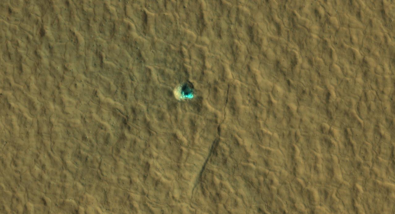
The ice-exposing impact crater at the center of this image is an example of what scientists look for when mapping places where future astronauts should land on Mars. NASA's Mars Reconnaissance Orbiter captured this view using its High-Resolution Imaging Science Experiment (HiRISE) camera on July 17, 2016. The color in this image has been enhanced for effect; water ice would not actually look this blue on Mars. The crater is estimated to be about 59 feet wide (18 meters wide). Surrounding the impact is a rough kind of surface known as "polygon terrain," which on Earth is known to form when subsurface ice expands and contracts repeatedly over time. Seeing this terrain surrounding an ice-exposing crater suggests much more ice could be found there. This impact is one of many included in a NASA-funded mapping project called Subsurface Water Ice Mapping, or SWIM. Mars has both water ice and carbon dioxide ice (dry ice); water ice would be a critical resource for the first astronauts to step foot on Mars, who can use it for drinking, rocket fuel, and other purposes. The more water ice these astronauts land next to, the less they need to bring with them. Because the Martian atmosphere is so thin – less than 1% the pressure experienced at sea level on Earth – liquid water is unstable on the Red Planet and will vaporize unless it's frozen. But water ice on the planet's surface is only stable at high latitudes that are far too cold for astronauts and robots to survive. So SWIM attempts to locate water ice preserved within the subsurface in the mid-latitudes, where landing would be feasible. Such regions are far enough toward the poles for water ice to be plentiful, but close enough to the equator to avoid the coldest temperatures seen on Mars. https://photojournal.jpl.nasa.gov/catalog/PIA26044
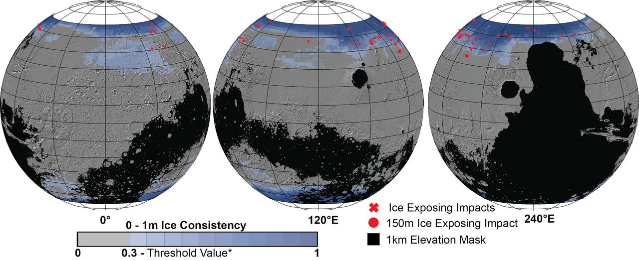
These Mars global maps show the likely distribution of water ice buried within the upper 3 feet (1 meter) of the planet's surface and represent the latest data from the Subsurface Water Ice Mapping project, or SWIM. SWIM uses data acquired by science instruments aboard three NASA orbital missions to estimate where ice may be hiding below the surface. Superimposed on the globes are the locations of ice-exposing meteoroid impacts, which provide an independent means to test the mapping results. The ice-exposing impacts were spotted by the High-Resolution Imaging Science Experiment (HiRISE), a camera aboard NASA's Mars Reconnaissance Orbiter. While other instruments at Mars can only suggest where buried water ice is located, HiRISE's imagery of ice-exposing impacts can confirm where ice is present. Most of these craters are no more than 33 feet (10 meters) in diameter, although in 2022 HiRISE captured a 492-foot-wide (150-meter-wide) impact crater that revealed a motherlode of ice that had been hiding beneath the surface. This crater is indicated with a circle in the upper-left portion of the right-most globe above. Scientists can use mapping data like this to decide where the first astronauts on Mars should land: Buried ice will be a vital resource for the first people to set foot on Mars, serving as drinking water and a key ingredient for rocket fuel. It would also be a major scientific target: Astronauts or robots could one day drill ice cores much as scientists do on Earth, uncovering the climate history of Mars and exploring potential habitats (past or present) for microbial life. The need to look for subsurface ice arises because liquid water isn't stable on the Martian surface: The atmosphere is so thin that water immediately vaporizes. There's plenty of ice at the Martian poles – mostly made of water, although carbon dioxide, or dry ice, can be found as well – but those regions are too cold for astronauts (or robots) to survive for long. https://photojournal.jpl.nasa.gov/catalog/PIA26046
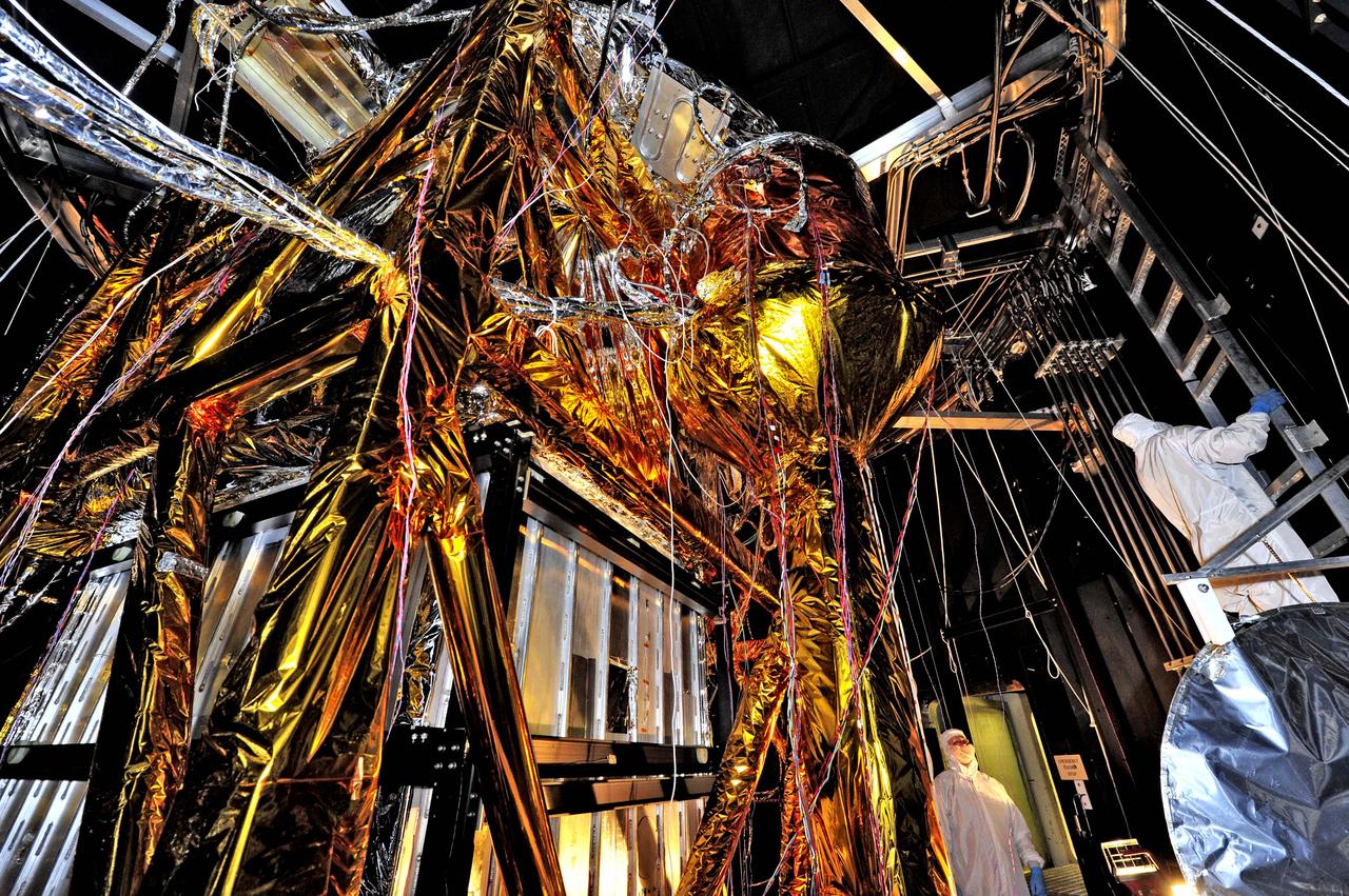
NASA image release August 23, 2012 What looks like a giant golden spider weaving a web of cables and cords, is actually ground support equipment, including the Optical Telescope Simulator (OSIM), for the James Webb Space Telescope. OSIM's job is to generate a beam of light just like the one that the real telescope optics will feed into the actual flight instruments. Because the real flight instruments will be used to test the real flight telescope, their alignment and performance first have to be verified by using the OSIM. Engineers are thoroughly checking out OSIM now in preparation for using it to test the flight science instruments later. This photo was taken from inside a large thermal-vacuum chamber called the Space Environment Simulator (SES), at NASA's Goddard Space Flight Center in Greenbelt, Md. Engineers have blanketed the structure of the OSIM with special insulating material to help control its temperature while it goes into the deep freeze testing that mimics the chill of space that Webb will ultimately experience in its operational orbit over 1 million miles from Earth. The golden-colored thermal blankets are made of aluminized kapton, a polymer film that remains stable over a wide range of temperatures. The structure that looks like a silver and black cube underneath the "spider" is a set of cold panels that surround OSIM's optics. During testing, OSIM's temperature will drop to 100 Kelvin (-280 F or -173 C) as liquid nitrogen flows through tubes welded to the chamber walls and through tubes along the silver panels surrounding OSIM's optics. These cold panels will keep the OSIM optics very cold, but the parts covered by the aluminized kapton blankets will stay warm. "Some blankets have silver facing out and gold facing in, or inverted, or silver on both sides, etc.," says Erin Wilson, a Goddard engineer. "Depending on which side of the blanket your hardware is looking at, the blankets can help it get colder or stay warmer, in an environmental test." Another reason for thermal blankets is to shield the cold OSIM optics from unwanted stray infrared light. When the OSIM is pointing its calibrated light beam at Webb's science instruments, engineers don't want any stray infrared light, such as "warm photons" from warm structures, leaking into the instruments' field of view. Too much of this stray light would raise the background too much for the instruments to "see" light from the OSIM—it would be like trying to photograph a lightning bug flying in front of car headlights. To get OSIM's optics cold, the inside of the chamber has to get cold, and to do that, all the air has to be pumped out to create a vacuum. Then liquid nitrogen has to be run though the plumbing along the inner walls of the chamber. Wilson notes that's why the blankets have to have vents in them: "That way, the air between all the layers can be evacuated as the chamber pressure drops, otherwise the blankets could pop," says Wilson. The most powerful space telescope ever built, Webb is the successor to NASA's Hubble Space Telescope. Webb's four instruments will reveal how the universe evolved from the Big Bang to the formation of our solar system. Webb is a joint project of NASA, the European Space Agency and the Canadian Space Agency. Credit: NASA/GSFC/Chris Gunn <b><a href="http://www.nasa.gov/audience/formedia/features/MP_Photo_Guidelines.html" rel="nofollow">NASA image use policy.</a></b> <b><a href="http://www.nasa.gov/centers/goddard/home/index.html" rel="nofollow">NASA Goddard Space Flight Center</a></b> enables NASA’s mission through four scientific endeavors: Earth Science, Heliophysics, Solar System Exploration, and Astrophysics. Goddard plays a leading role in NASA’s accomplishments by contributing compelling scientific knowledge to advance the Agency’s mission. <b>Follow us on <a href="http://twitter.com/NASA_GoddardPix" rel="nofollow">Twitter</a></b> <b>Like us on <a href="http://www.facebook.com/pages/Greenbelt-MD/NASA-Goddard/395013845897?ref=tsd" rel="nofollow">Facebook</a></b> <b>Find us on <a href="http://instagrid.me/nasagoddard/?vm=grid" rel="nofollow">Instagram</a></b>