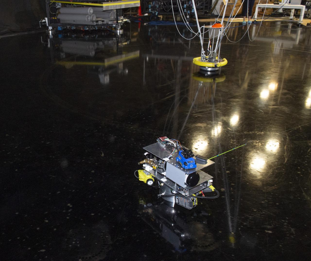
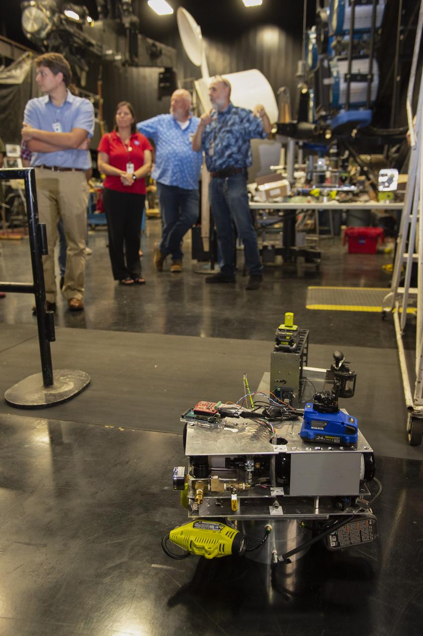
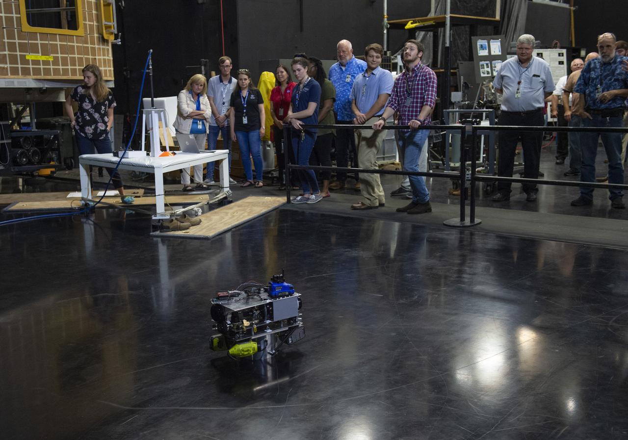
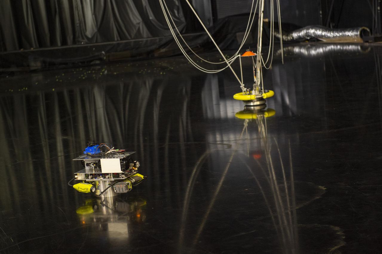
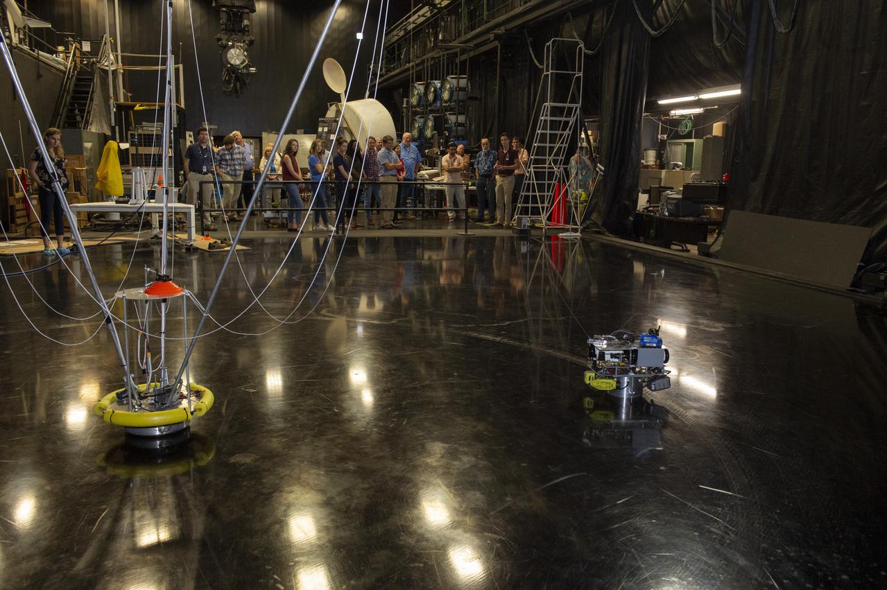
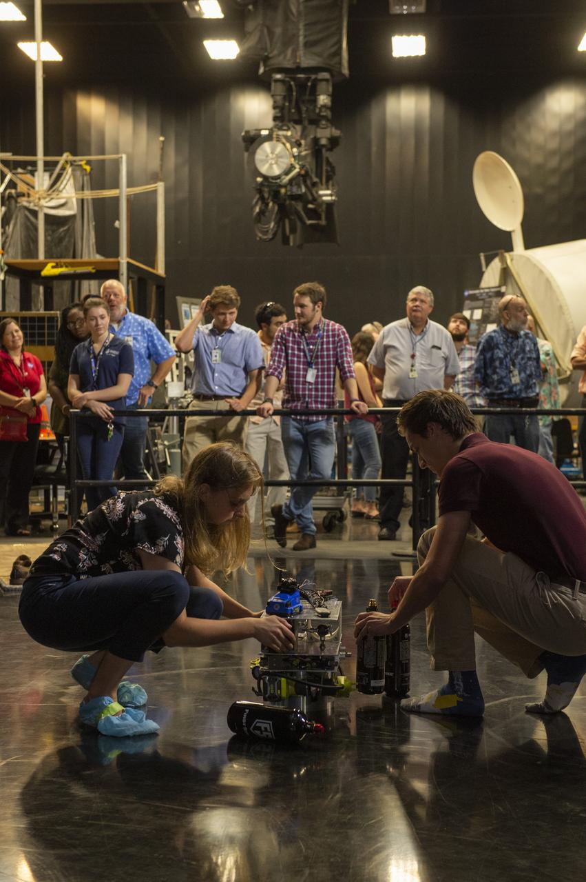
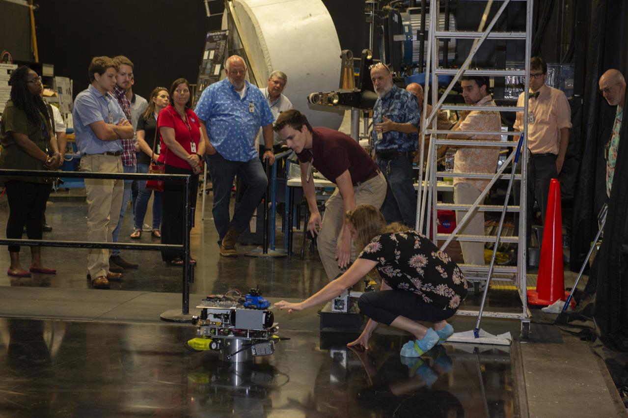
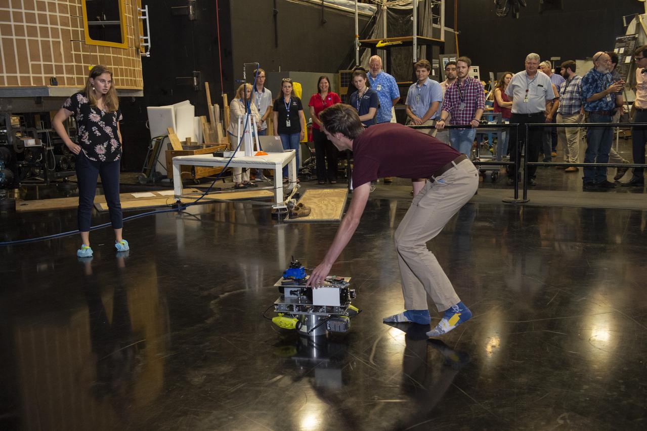
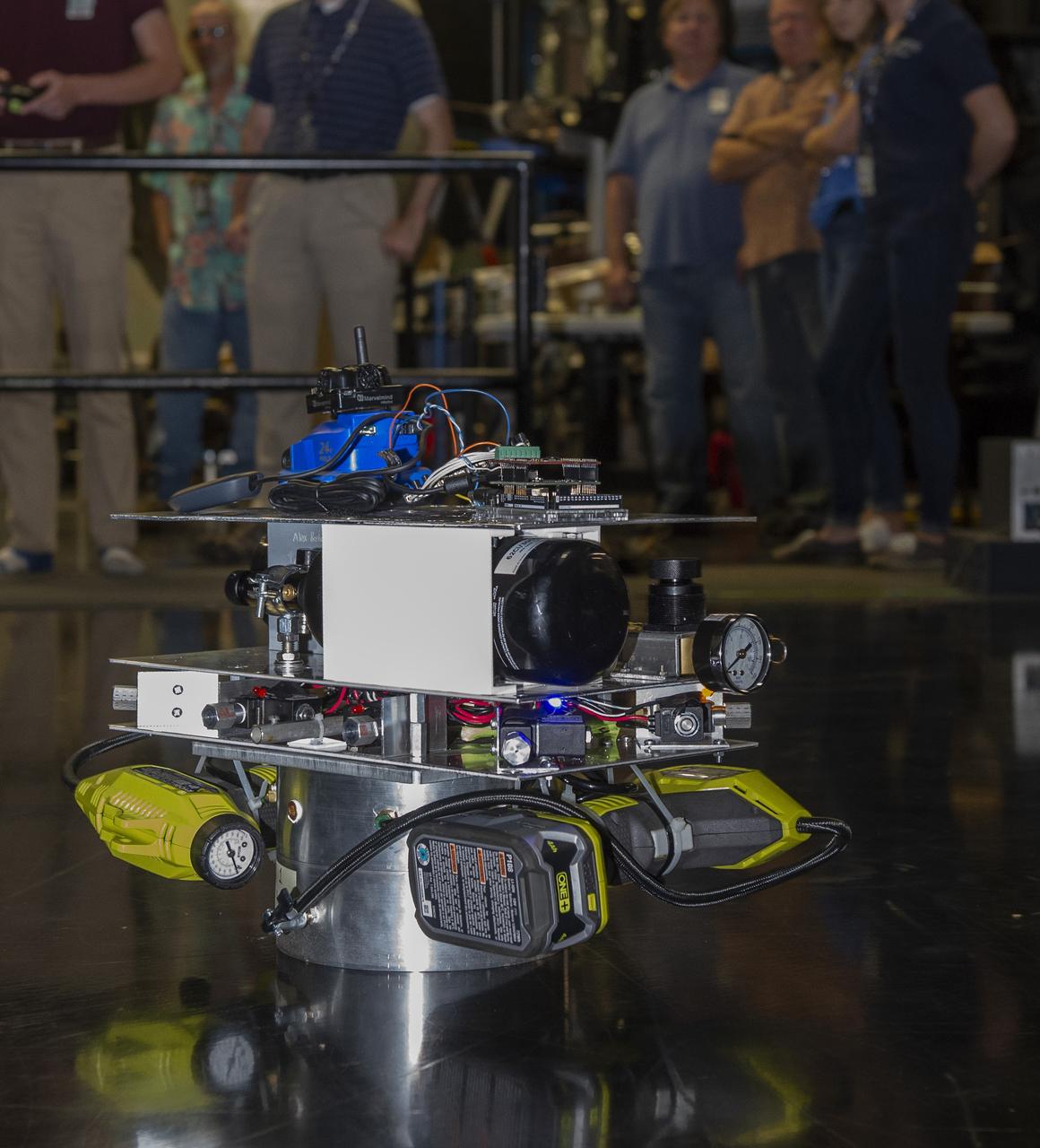
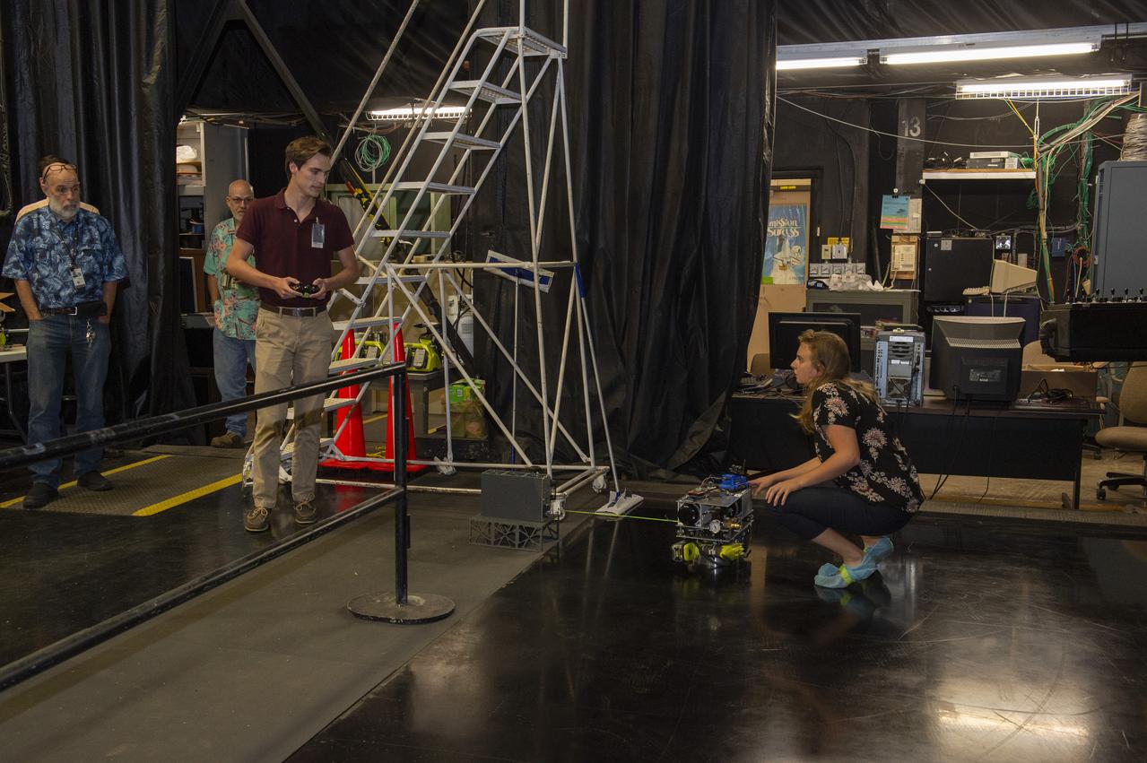
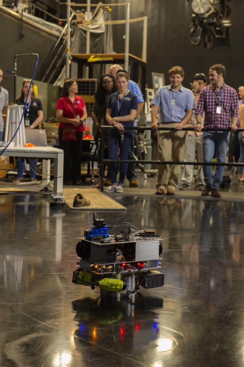
PATHWAYS INTERN ALEXANDRA BOEHM, AND JACOBS INTERN, PEYTON NELSON DEMONSTRATE STEERABLE AIR BEARING TETHER DEPLOYMENT SYSTEM TO MSFC SENIOR MANAGEMENT. ALSO WORKING ON THE PROJECT BUT NOT PICTURED WERE SUMMER INTERN ALI BERTELSMAN, PATHWAYS INTERN ANNA SHIPMAN, AND JACOBS FULL-TIME EMPLOYEE BRANDON MOORE.
PATHWAYS INTERN ALEXANDRA BOEHM, AND JACOBS INTERN, PEYTON NELSON DEMONSTRATE STEERABLE AIR BEARING TETHER DEPLOYMENT SYSTEM TO MSFC SENIOR MANAGEMENT. ALSO WORKING ON THE PROJECT BUT NOT PICTURED WERE SUMMER INTERN ALI BERTELSMAN, PATHWAYS INTERN ANNA SHIPMAN, AND JACOBS FULL-TIME EMPLOYEE BRANDON MOORE.
PATHWAYS INTERN ALEXANDRA BOEHM, AND JACOBS INTERN, PEYTON NELSON DEMONSTRATE STEERABLE AIR BEARING TETHER DEPLOYMENT SYSTEM TO MSFC SENIOR MANAGEMENT. ALSO WORKING ON THE PROJECT BUT NOT PICTURED WERE SUMMER INTERN ALI BERTELSMAN, PATHWAYS INTERN ANNA SHIPMAN, AND JACOBS FULL-TIME EMPLOYEE BRANDON MOORE.
PATHWAYS INTERN ALEXANDRA BOEHM, AND JACOBS INTERN, PEYTON NELSON DEMONSTRATE STEERABLE AIR BEARING TETHER DEPLOYMENT SYSTEM TO MSFC SENIOR MANAGEMENT. ALSO WORKING ON THE PROJECT BUT NOT PICTURED WERE SUMMER INTERN ALI BERTELSMAN, PATHWAYS INTERN ANNA SHIPMAN, AND JACOBS FULL-TIME EMPLOYEE BRANDON MOORE.
PATHWAYS INTERN ALEXANDRA BOEHM, AND JACOBS INTERN, PEYTON NELSON DEMONSTRATE STEERABLE AIR BEARING TETHER DEPLOYMENT SYSTEM TO MSFC SENIOR MANAGEMENT. ALSO WORKING ON THE PROJECT BUT NOT PICTURED WERE SUMMER INTERN ALI BERTELSMAN, PATHWAYS INTERN ANNA SHIPMAN, AND JACOBS FULL-TIME EMPLOYEE BRANDON MOORE.
PATHWAYS INTERN ALEXANDRA BOEHM, AND JACOBS INTERN, PEYTON NELSON DEMONSTRATE STEERABLE AIR BEARING TETHER DEPLOYMENT SYSTEM TO MSFC SENIOR MANAGEMENT. ALSO WORKING ON THE PROJECT BUT NOT PICTURED WERE SUMMER INTERN ALI BERTELSMAN, PATHWAYS INTERN ANNA SHIPMAN, AND JACOBS FULL-TIME EMPLOYEE BRANDON MOORE.
PATHWAYS INTERN ALEXANDRA BOEHM, AND JACOBS INTERN, PEYTON NELSON DEMONSTRATE STEERABLE AIR BEARING TETHER DEPLOYMENT SYSTEM TO MSFC SENIOR MANAGEMENT. ALSO WORKING ON THE PROJECT BUT NOT PICTURED WERE SUMMER INTERN ALI BERTELSMAN, PATHWAYS INTERN ANNA SHIPMAN, AND JACOBS FULL-TIME EMPLOYEE BRANDON MOORE.
PATHWAYS INTERN ALEXANDRA BOEHM, AND JACOBS INTERN, PEYTON NELSON DEMONSTRATE STEERABLE AIR BEARING TETHER DEPLOYMENT SYSTEM TO MSFC SENIOR MANAGEMENT. ALSO WORKING ON THE PROJECT BUT NOT PICTURED WERE SUMMER INTERN ALI BERTELSMAN, PATHWAYS INTERN ANNA SHIPMAN, AND JACOBS FULL-TIME EMPLOYEE BRANDON MOORE.

PATHWAYS INTERN ALEXANDRA BOEHM, AND JACOBS INTERN, PEYTON NELSON DEMONSTRATE STEERABLE AIR BEARING TETHER DEPLOYMENT SYSTEM TO MSFC SENIOR MANAGEMENT. ALSO WORKING ON THE PROJECT BUT NOT PICTURED WERE SUMMER INTERN ALI BERTELSMAN, PATHWAYS INTERN ANNA SHIPMAN, AND JACOBS FULL-TIME EMPLOYEE BRANDON MOORE.
PATHWAYS INTERN ALEXANDRA BOEHM, AND JACOBS INTERN, PEYTON NELSON DEMONSTRATE STEERABLE AIR BEARING TETHER DEPLOYMENT SYSTEM TO MSFC SENIOR MANAGEMENT. ALSO WORKING ON THE PROJECT BUT NOT PICTURED WERE SUMMER INTERN ALI BERTELSMAN, PATHWAYS INTERN ANNA SHIPMAN, AND JACOBS FULL-TIME EMPLOYEE BRANDON MOORE.
PATHWAYS INTERN ALEXANDRA BOEHM, AND JACOBS INTERN, PEYTON NELSON DEMONSTRATE STEERABLE AIR BEARING TETHER DEPLOYMENT SYSTEM TO MSFC SENIOR MANAGEMENT. ALSO WORKING ON THE PROJECT BUT NOT PICTURED WERE SUMMER INTERN ALI BERTELSMAN, PATHWAYS INTERN ANNA SHIPMAN, AND JACOBS FULL-TIME EMPLOYEE BRANDON MOORE.
PATHWAYS INTERN ALEXANDRA BOEHM, AND JACOBS INTERN, PEYTON NELSON DEMONSTRATE STEERABLE AIR BEARING TETHER DEPLOYMENT SYSTEM TO MSFC SENIOR MANAGEMENT. ALSO WORKING ON THE PROJECT BUT NOT PICTURED WERE SUMMER INTERN ALI BERTELSMAN, PATHWAYS INTERN ANNA SHIPMAN, AND JACOBS FULL-TIME EMPLOYEE BRANDON MOORE.
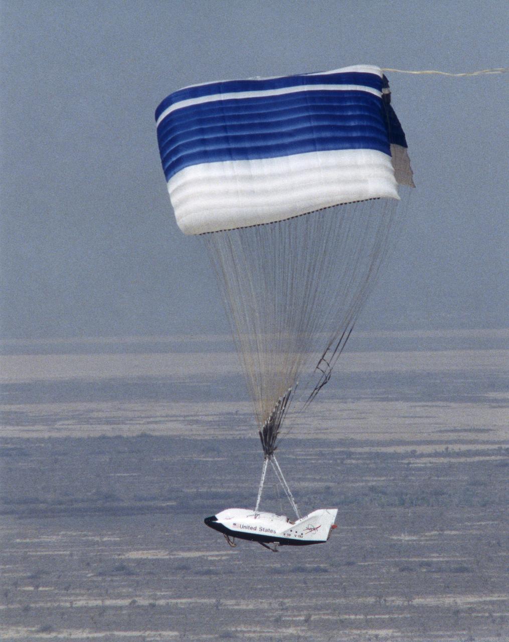
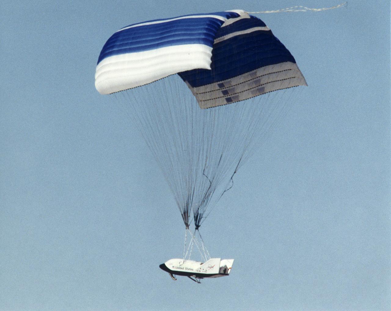
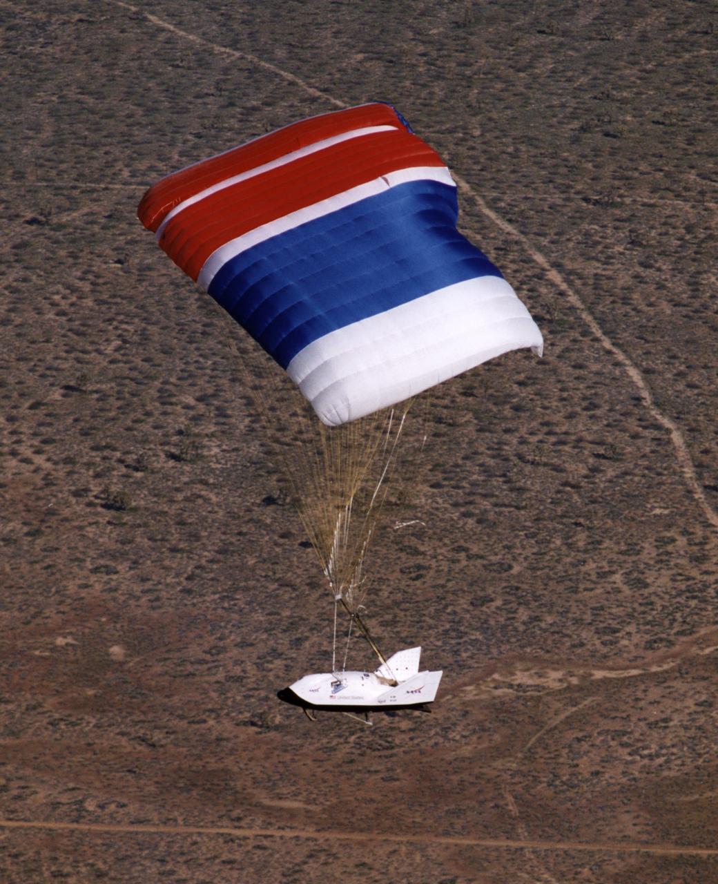
The X-38 technology demonstrator descends under its steerable parafoil toward a lakebed landing in a March 2000 test flight.
The X-38 technology demonstrator descends under its steerable parafoil toward a lakebed landing in a March 2000 test flight.
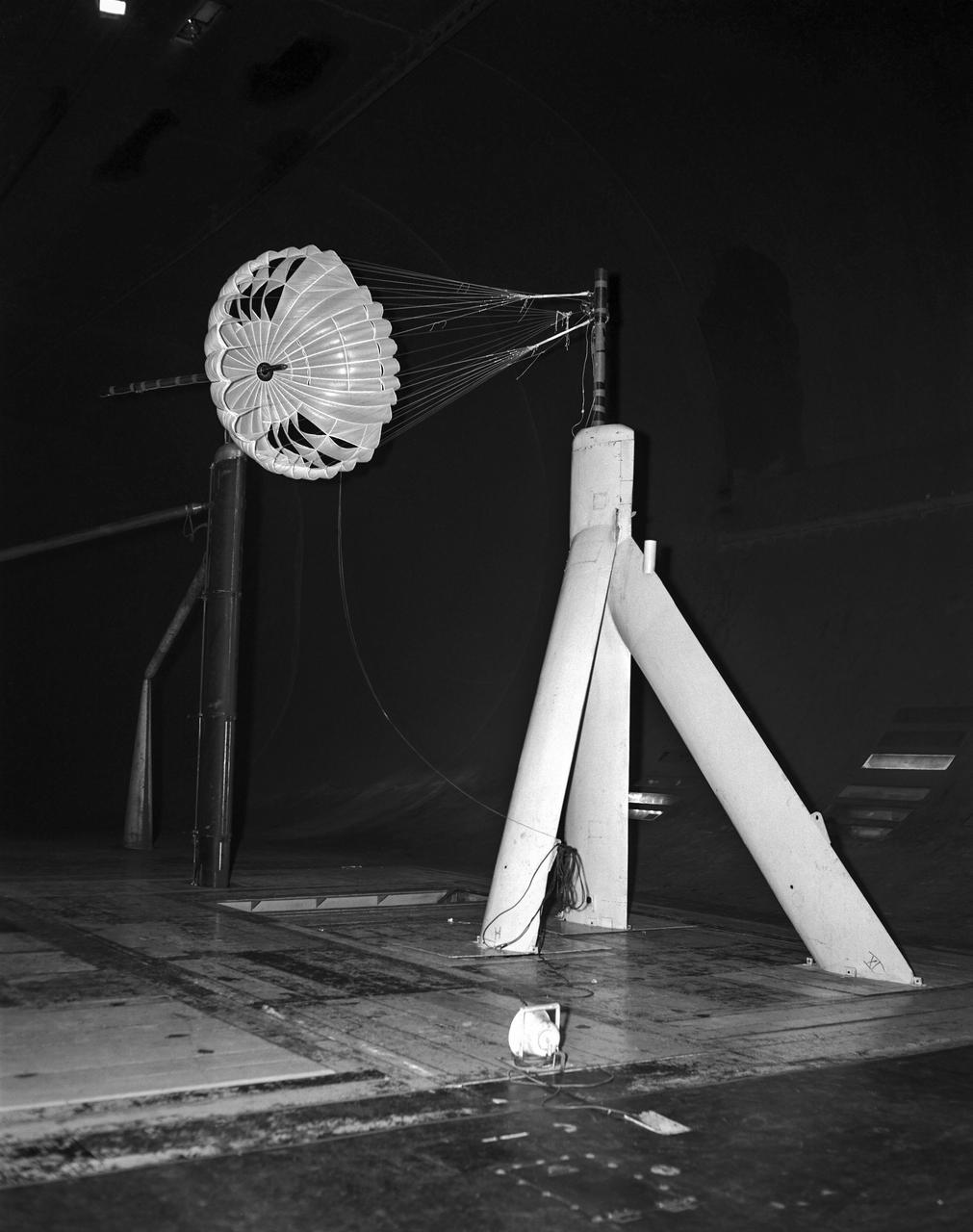
Gliding parachute test in 40x80 foot Wind Tunnel, mounted on main strut flying horizontally.
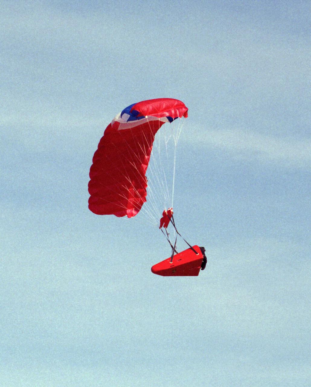
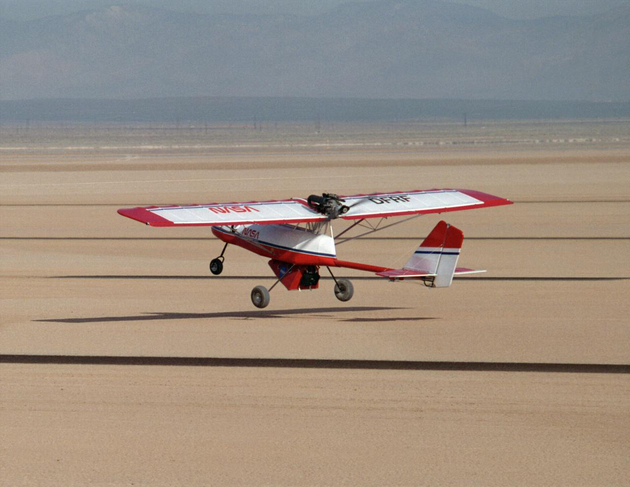
One of the Spacewedge remotely-piloted research vehicles in flight under a steerable parafoil during 1995 research flights conducted by NASA’s Dryden Flight Research Center.
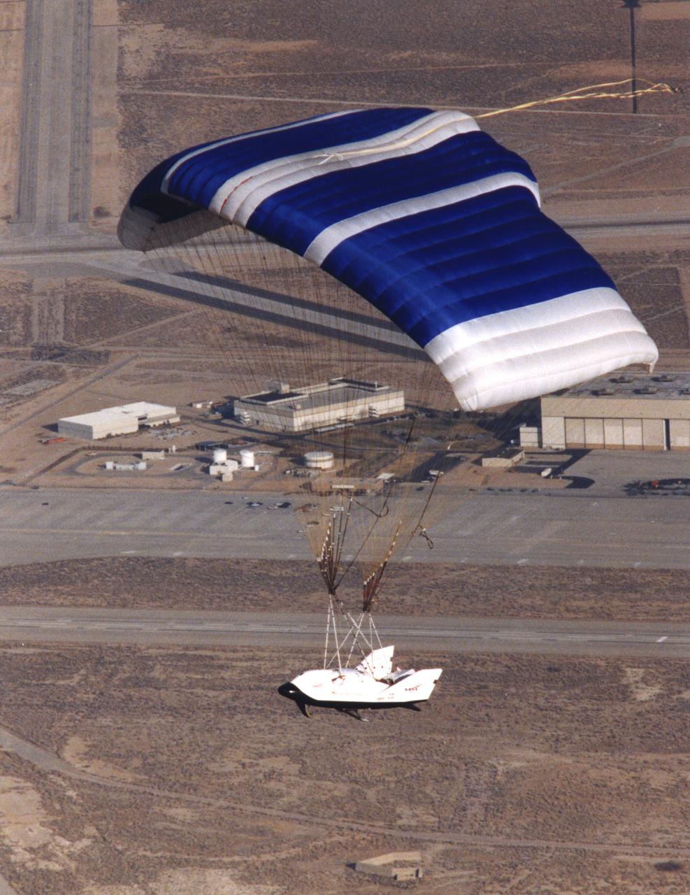
The X-38, a research vehicle built to help develop technology for an emergency Crew Return Vehicle (CRV), descends under its steerable parafoil on a March 1999 test flight at the Dryden Flight Research Center, Edwards, California.
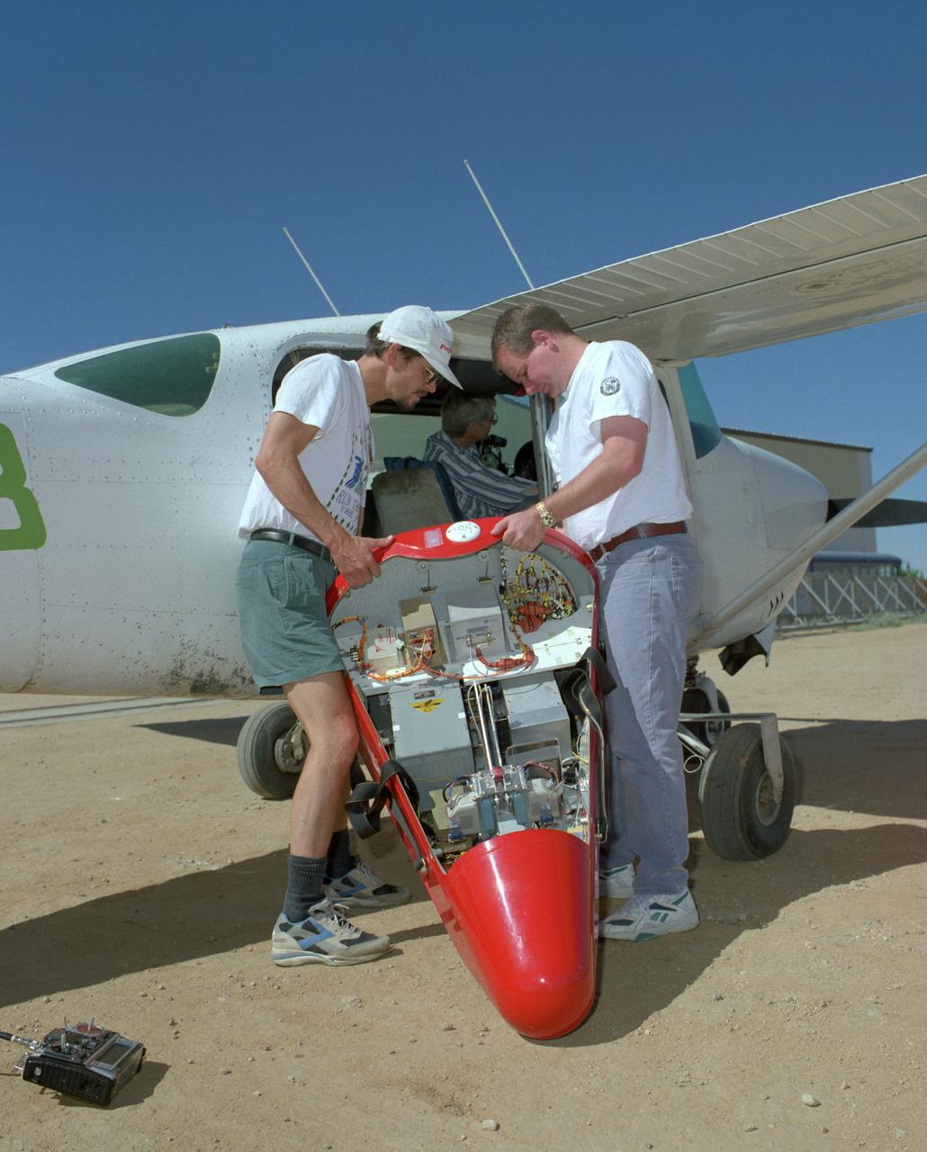
Crew members load a Spacewedge subscale research model into a Cessna aircraft for flight testing in 1996. The Spacewedge was drop-launched from the Cessna and then glided back to a soft landing under a steerable parafoil.
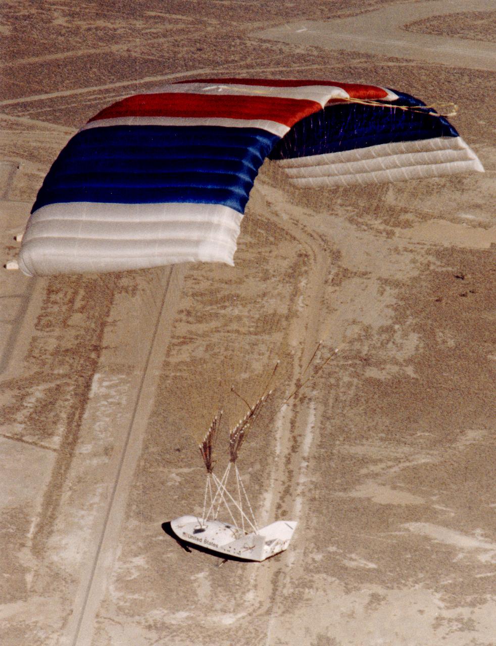
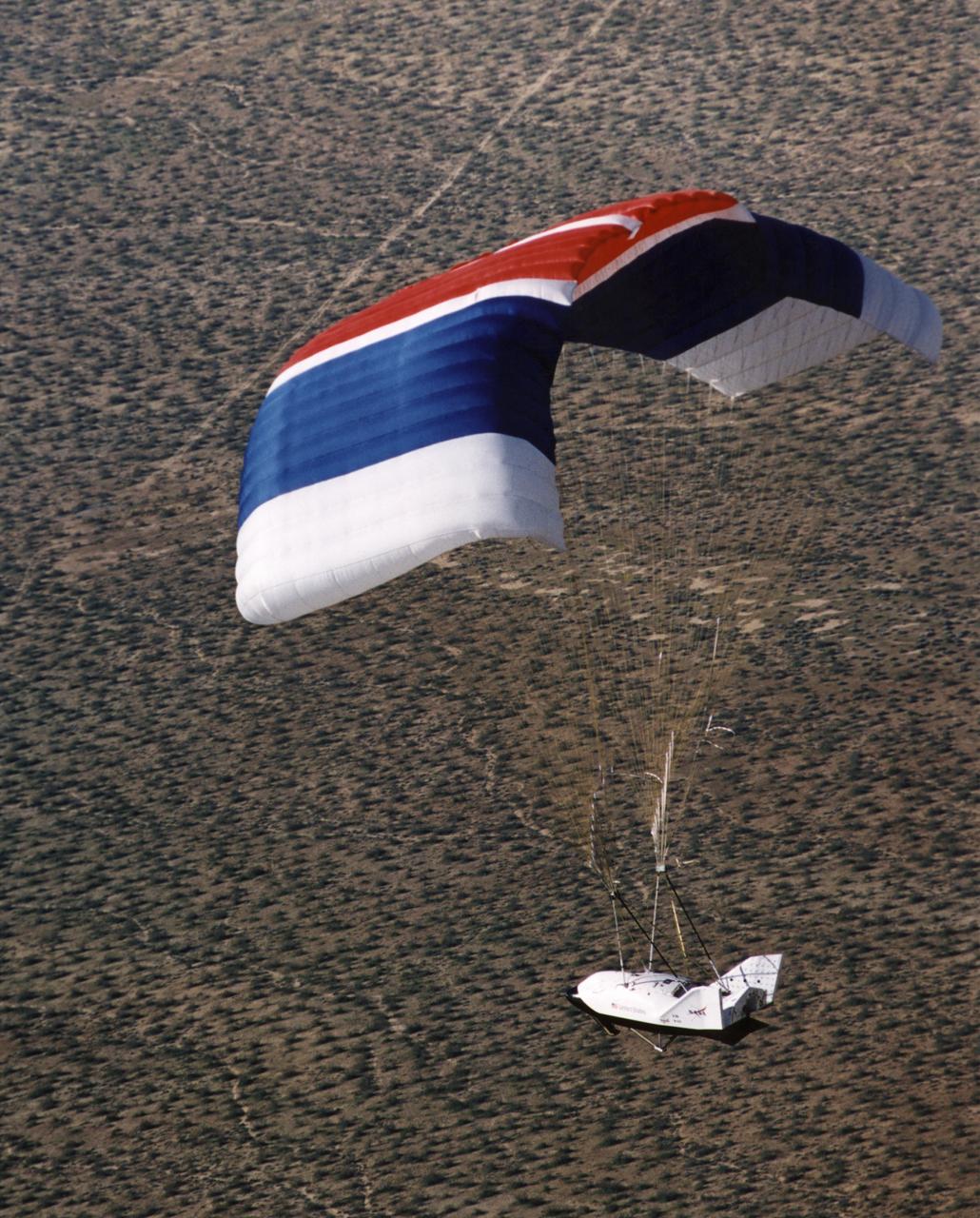
The X-38 Crew Return Vehicle descends under its steerable parafoil over the California desert during its first free flight in March 1998 at the Dryden Flight Research Center, Edwards, California.
The X-38, a research vehicle built to help develop technology for an emergency Crew Return Vehicle (CRV), descends under its steerable parafoil on a March 1999 test flight at the Dryden Flight Research Center, Edwards, California.
The X-38, a research vehicle built to help develop technology for an emergency Crew Return Vehicle (CRV), descends under its steerable parafoil on a March 1999 test flight at the Dryden Flight Research Center, Edwards, California.
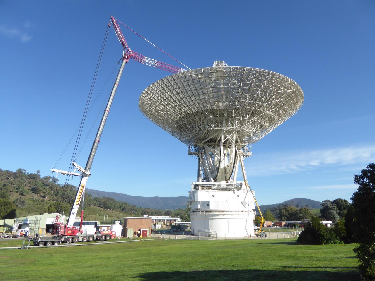
Located in Canberra, Australia, the Deep Space Network's Deep Space Station 43 spans 70 meters (230 feet), making it the largest steerable parabolic antenna in the Southern Hemisphere. Since March 2020, it has been undergoing upgrades — expected to be complete in January 2021 — to prepare the 48-year-old dish for future exploration of the Moon, Mars, and beyond. NASA operates three Deep Space Network stations, located in California, Spain, and Australia; each has a 70-meter (230-feet) antenna, plus several 34-meter (111-foot) dishes to support dozens of spacecraft exploring the solar system. https://photojournal.jpl.nasa.gov/catalog/PIA23797
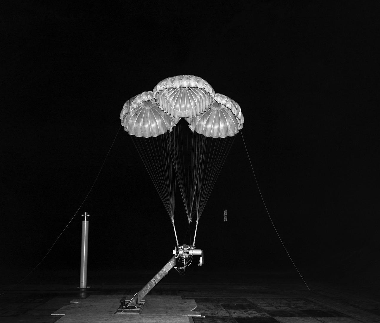
(02/18/1964) Apollo 3 Parachute cluster, flown vertically in 40x80 wind tunnel. Parachutes mounted on a control head with reels to vary the line lengths.
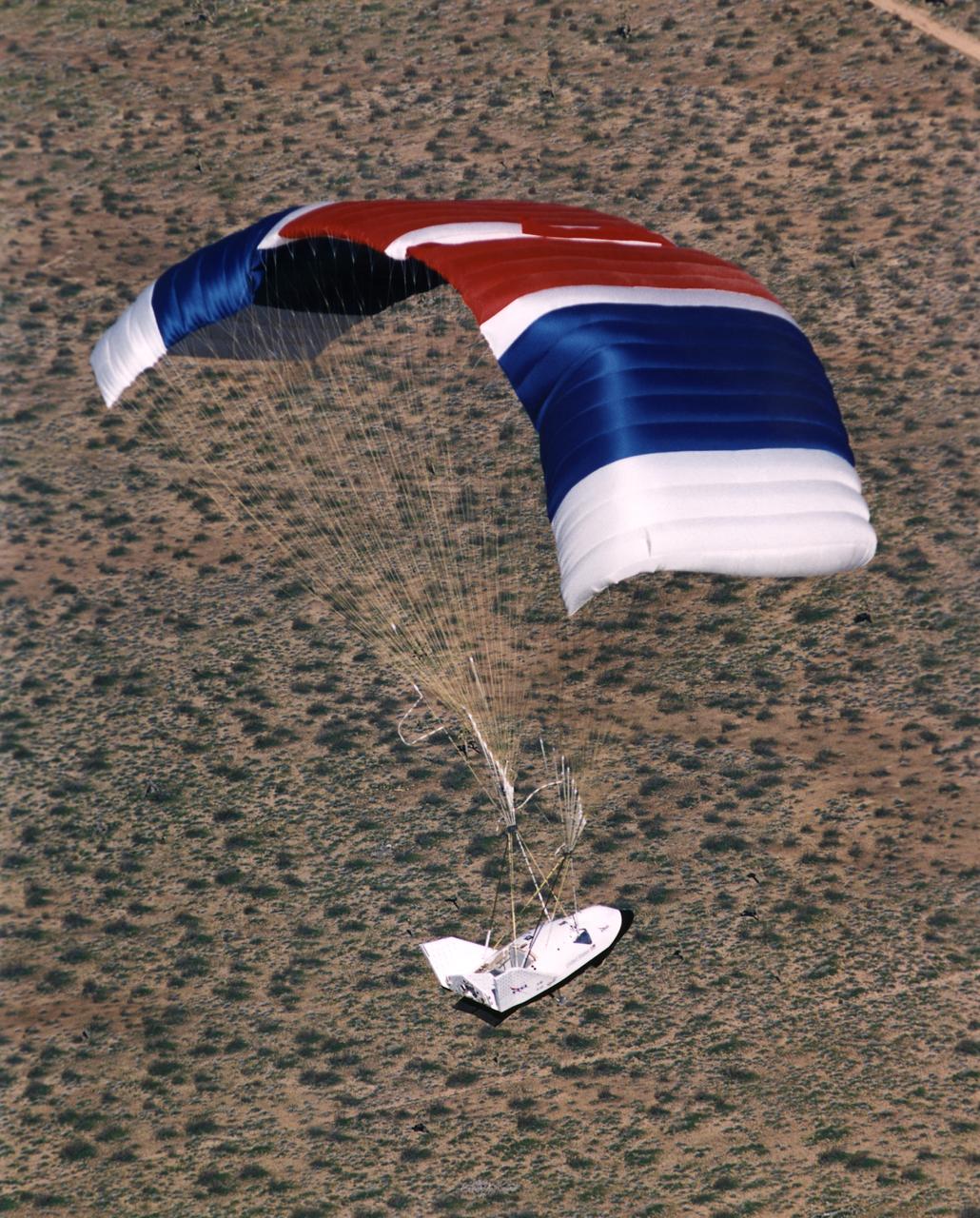
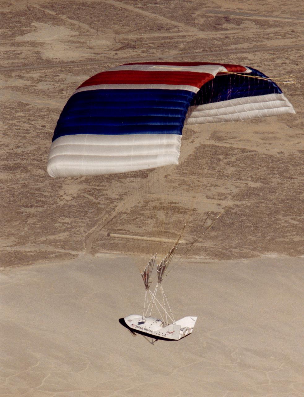
The X-38 Crew Return Vehicle descends under its steerable parafoil over the California desert in its first free flight at the Dryden Flight Research Center, Edwards, California. The flight took place March 12, 1998.
The X-38 Crew Return Vehicle descends under its steerable parafoil over the California desert in its first free flight at the Dryden Flight Research Center, Edwards, California. The flight took place March 12, 1998.
The X-38 Crew Return Vehicle descends under its steerable parafoil over the California desert in its first free flight at the Dryden Flight Research Center, Edwards, California. The flight took place March 12, 1998.
The X-38 Crew Return Vehicle descends under its steerable parafoil over the California desert in its first free flight at the Dryden Flight Research Center, Edwards, California. The flight took place March 12, 1998.
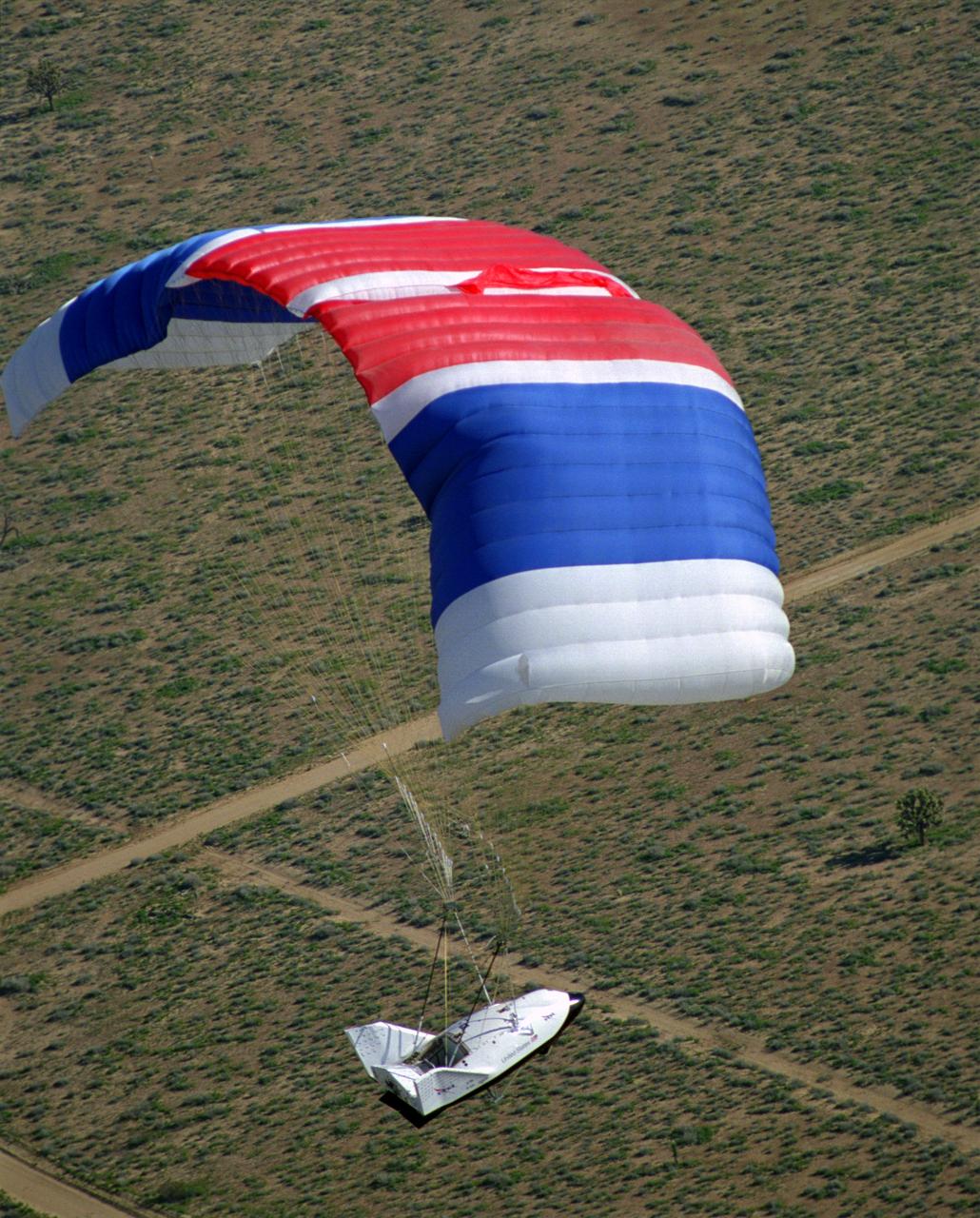
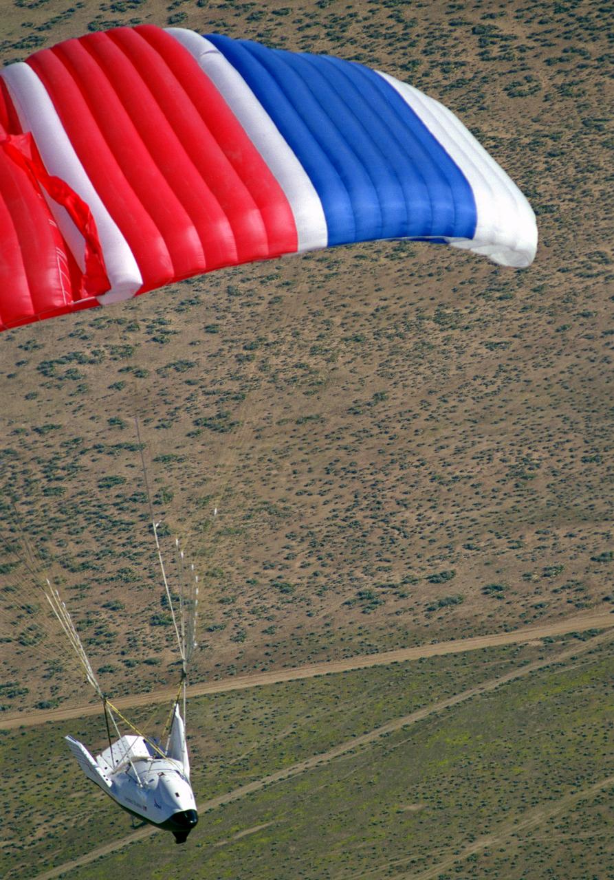
NASA's X-38, a research vehicle developed as part of an effort to build an emergency Crew Return Vehicle (CRV) for the International Space Station, descends toward the desert floor under its steerable parafoil on its second free flight. The X-38 was launched from NASA Dryden's B-52 Mothership on Saturday, February 6, 1999, from an altitude of approximately 23,000 feet.
NASA's X-38, a research vehicle developed as part of an effort to build an emergency Crew Return Vehicle (CRV) for the International Space Station, descends toward the desert floor under its steerable parafoil on its second free flight. The X-38 was launched from NASA Dryden's B-52 Mothership on Saturday, February 6, 1999, from an altitude of approximately 23,000 feet.
A Rans S-12 remotely piloted "mothership" takes off from a lakebed runway carrying a Spacewedge research model during 1992 flight tests. The Spacewedge was lauched in flight from the Rans S-12 aircraft and then glided back to a landing under a steerable parafoil. Technology tested in the Spacewedge program was used in developing the X-38 research vehicle.
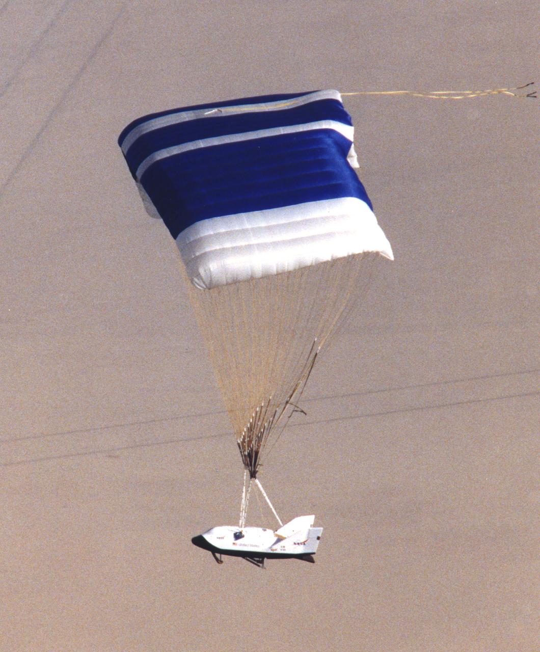
NASA's X-38, a research vehicle developed as part of an effort to build an emergency Crew Return Vehicle (CRV) for the International Space Station, descends toward a desert lakebed under its steerable parafoil on its second free flight. The X-38 was launched from NASA Dryden's B-52 Mothership on Saturday, February 6, 1999, from an altitude of approximately 23,000 feet.
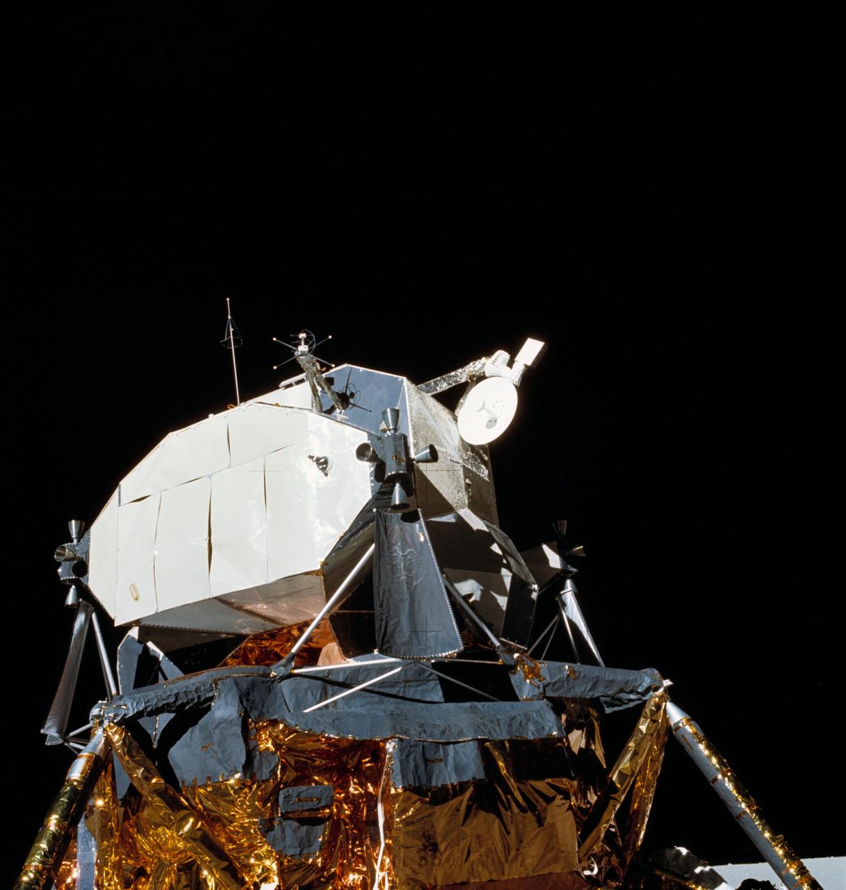
AS16-113-18334 (21 April 1972) --- View of the Lunar Module (LM) "Orion" parked on the lunar surface. During their post mission press conference, the Apollo 16 crewmembers called attention to the steerable S-band antenna, which was "frozen" in a yaw axis during much of the flight. This view of the LM was photographed by astronaut Charles M. Duke Jr., the lunar module pilot, during the mission's first extravehicular activity (EVA). Astronauts John W. Young, commander, and Duke had earlier descended in the LM to explore the Descartes region of the moon, while astronaut Thomas K. Mattingly II, command module pilot, remained with the Command and Service Modules (CSM) "Casper" in lunar orbit.
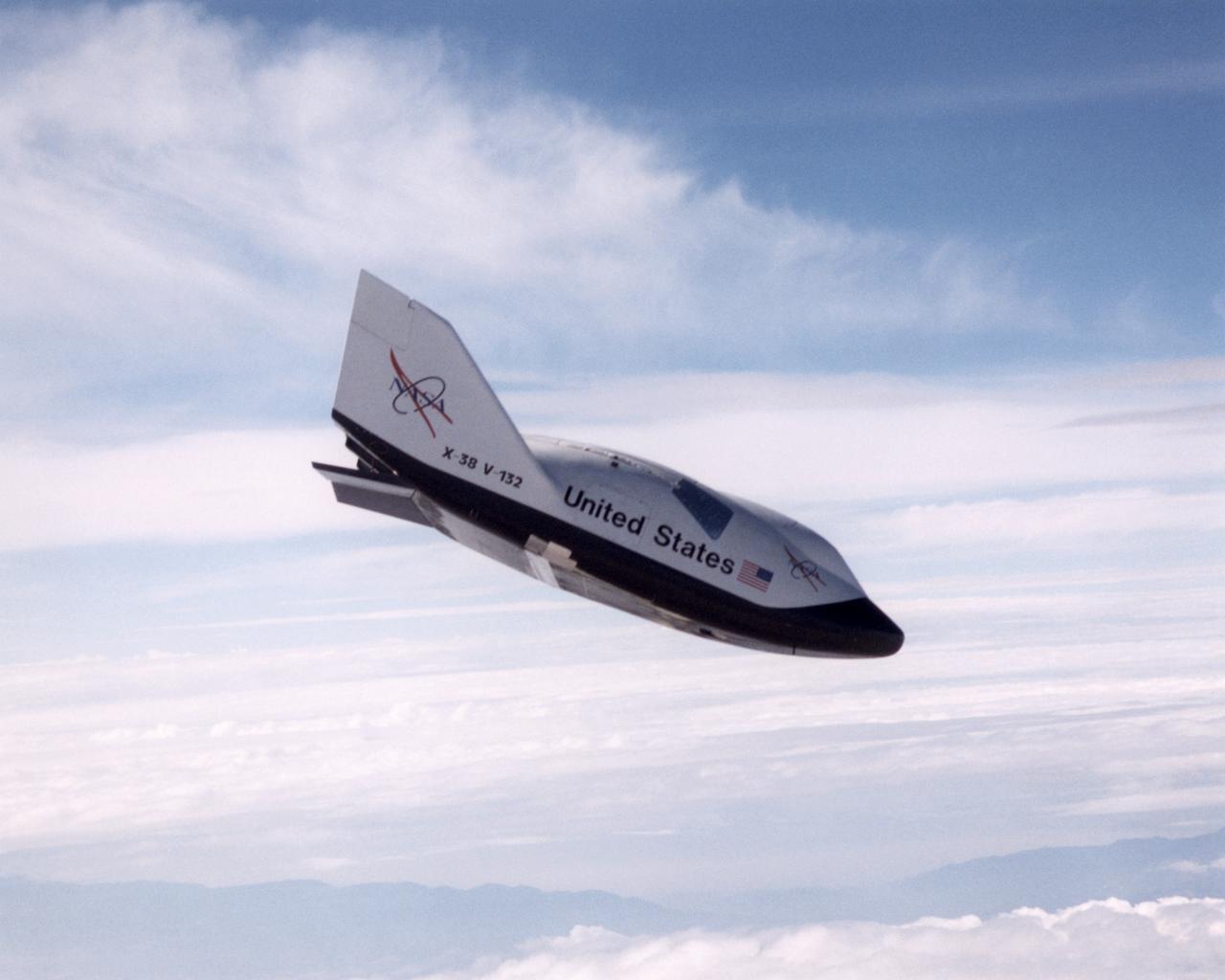
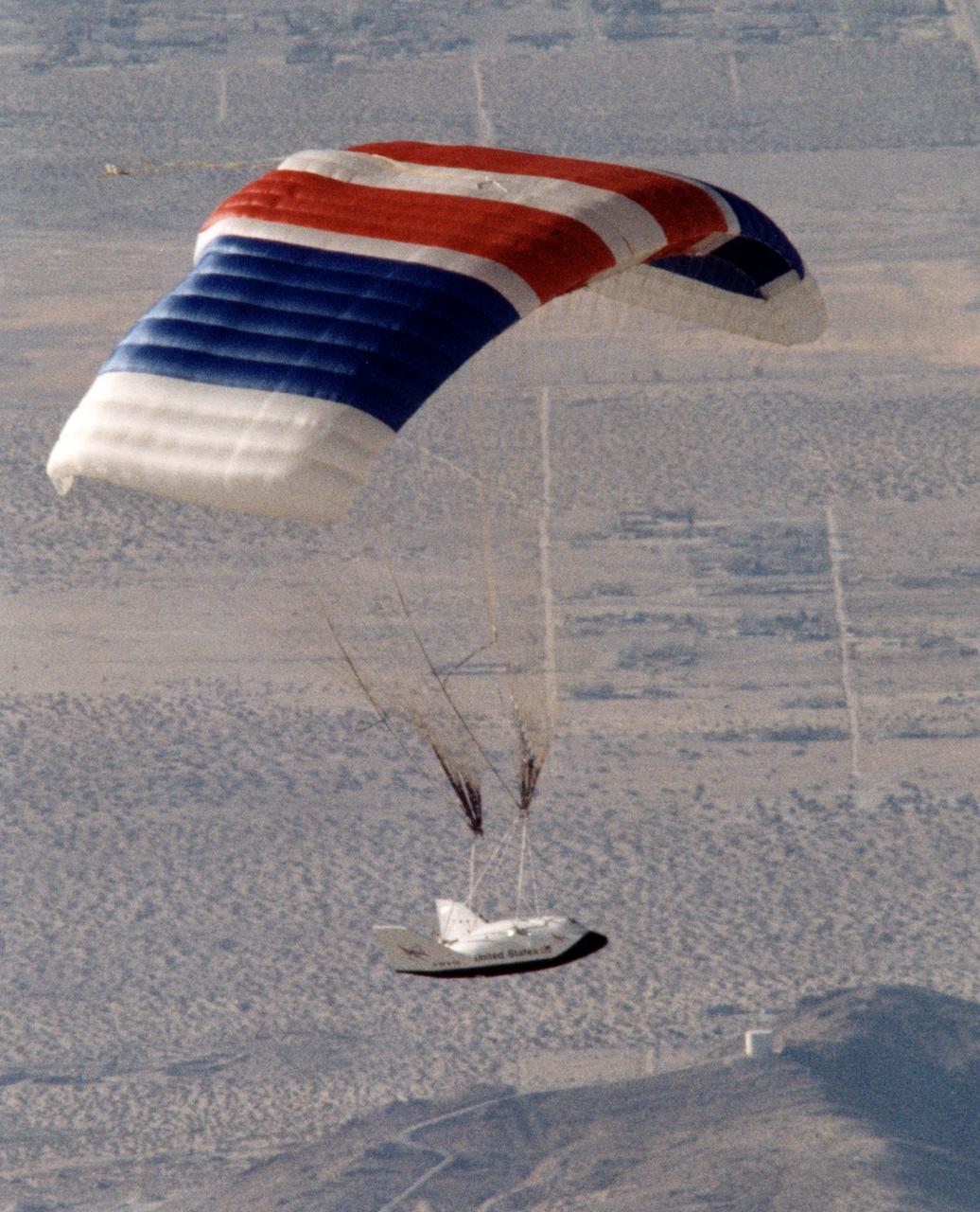
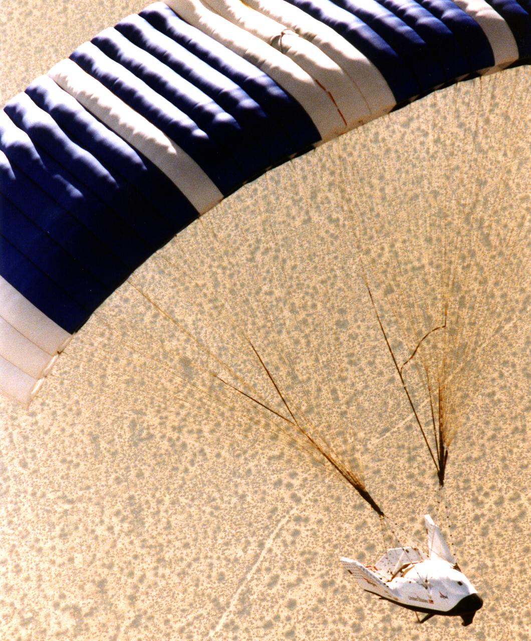
The X-38, a research vehicle built to help develop technology for an emergency Crew Return Vehicle (CRV), descends under its steerable parachute during a July 1999 test flight at the Dryden Flight Research Center, Edwards, California. It was the fourth free flight of the test vehicles in the X-38 program, and the second free flight test of Vehicle 132 or Ship 2. The goal of this flight was to release the vehicle from a higher altitude -- 31,500 feet -- and to fly the vehicle longer -- 31 seconds -- than any previous X-38 vehicle had yet flown. The project team also conducted aerodynamic verification maneuvers and checked improvements made to the drogue parachute.
CAPE CANAVERAL, Fla. – Positioned on its 12-wheeled, 24-tire transporter, the payload canister with the STS-124 mission payload, Japanese Experiment Module - Pressurized Module and the Japanese Remote Manipulator System, or RMS, inside, begins its slow journey to Launch Pad 39A at NASA's Kennedy Space Center. At the pad, the payload will be transferred into the payload changeout room on the rotating service structure. The transporter is 65 feet long and 23 feet wide. The transporter’s wheels are independently steerable, permitting it to move forward, backward, sideways or diagonally and to turn on its own axis like a carousel. It is equipped with pneumatic-actuated braking and hydrostat¬ic leveling and drive systems. It is steered from a two-seat operator cab mounted at one end. From the payload changeout room, the pressurized module and RMS then will be transferred into space shuttle Discovery’s payload bay. Launch is targeted for May 31. Photo credit: NASA/Kim Shiflett
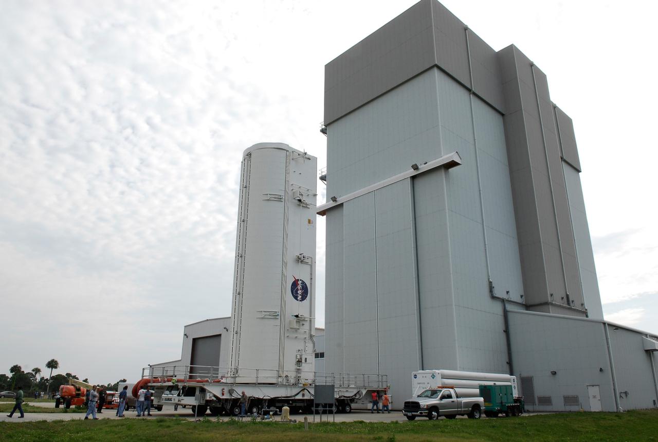
CAPE CANAVERAL, Fla. – Positioned on its 12-wheeled, 24-tire transporter, the payload canister with the STS-124 mission payload, Japanese Experiment Module - Pressurized Module and the Japanese Remote Manipulator System, or RMS, inside, slowly passes the Vehicle Assembly Building at NASA's Kennedy Space Center, on its journey to Launch Pad 39A. At the pad, the payload will be transferred into the payload changeout room on the rotating service structure. The transporter is 65 feet long and 23 feet wide. The transporter’s wheels are independently steerable, permitting it to move forward, backward, sideways or diagonally and to turn on its own axis like a carousel. It is equipped with pneumatic-actuated braking and hydrostat¬ic leveling and drive systems. It is steered from a two-seat operator cab mounted at one end. From the payload changeout room, the pressurized module and RMS then will be transferred into space shuttle Discovery’s payload bay. Launch is targeted for May 31. Photo credit: NASA/Kim Shiflett
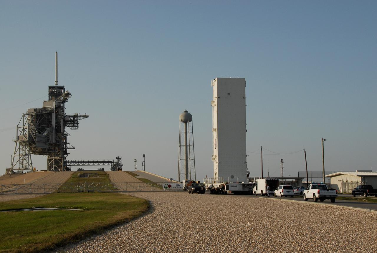
CAPE CANAVERAL, Fla. -- Positioned on its 12-wheeled, 24-tire transporter, the payload canister with the STS-124 mission payload, Japanese Experiment Module - Pressurized Module and the Japanese Remote Manipulator System, or RMS, inside, approaches the ramp to Launch Pad 39A at NASA's Kennedy Space Center. The transporter is 65 feet long and 23 feet wide. The transporter’s wheels are independently steerable, permitting it to move forward, backward, sideways or diagonally and to turn on its own axis like a carousel. It is equipped with pneumatic-actuated braking and hydrostat¬ic leveling and drive systems. It is steered from a two-seat operator cab mounted at one end. From the payload changeout room, the pressurized module and RMS will be transferred into space shuttle Discovery’s payload bay. Launch is targeted for May 31. Photo credit: NASA/Kim Shiflett
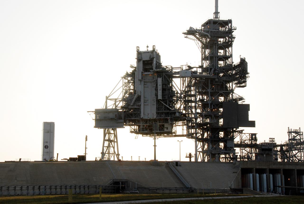
CAPE CANAVERAL, Fla. – On Launch Pad 39A at NASA's Kennedy Space Center, the payload changeout room on the rotating service structure at center is open and ready to receive the STS-124 mission payload inside the approaching payload canister at far left. The payload is composed of the Japanese Experiment Module - Pressurized Module and the Japanese Remote Manipulator System, or RMS. The canister will be lifted up to the changeout room and the payload transferred inside. The changeout room is the enclosed, environmentally controlled portion of the service structure that supports cargo delivery to the pad and subsequent vertical installation into an orbiter's payload bay. At the pad, the payload will be transferred into the payload changeout room on the rotating service structure. The transporter is 65 feet long and 23 feet wide. The transporter’s wheels are independently steerable, permitting it to move forward, backward, sideways or diagonally and to turn on its own axis like a carousel. It is equipped with pneumatic-actuated braking and hydrostat¬ic leveling and drive systems. It is steered from a two-seat operator cab mounted at one end. From the payload changeout room, the pressurized module and RMS then will be transferred into space shuttle Discovery’s payload bay. Launch is targeted for May 31. Photo credit: NASA/Kim Shiflett
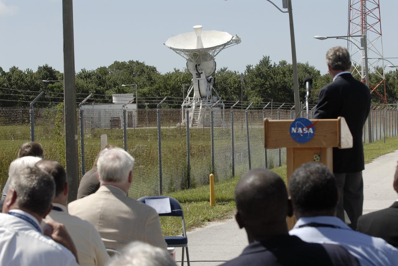
CAPE CANAVERAL, Fla. -- At the Merritt Island Launch Annex (MILA) Spaceflight Tracking and Data Network Station at NASA's Kennedy Space Center in Florida, one of two signature 30-foot steerable S-band antennas is slewed from the horizontal to the vertical position for the last time during a closing ceremony recognizing the station's 45 years of service. The antenna was pointed at Kennedy's Shuttle Landing Facility as it was for its last assignment, support of the landing of space shuttle Atlantis, concluding the STS-135 mission. STS-135 was the final mission of the Space Shuttle Program. The station was originally established by NASA's Goddard Space Flight Center as one of 17 Space Flight Tracking and Data Network stations around the world. Commissioned for the Apollo Program, the first launch it supported was the Apollo/Saturn 203 test flight from Launch Complex 37 on July 5, 1966. It also provided orbital support for low earth-orbiting scientific satellites. In recent history, the station has been used almost exclusively for space shuttle launch and landing support. Following the final launch and landing of the Space Shuttle Program in July 2011, the MILA station is officially decommissioned. For more information, visit http://www.nasa.gov/centers/kennedy/pdf/167424main_MILA-08C.pdf. Photo credit: NASA/Kim Shiflett
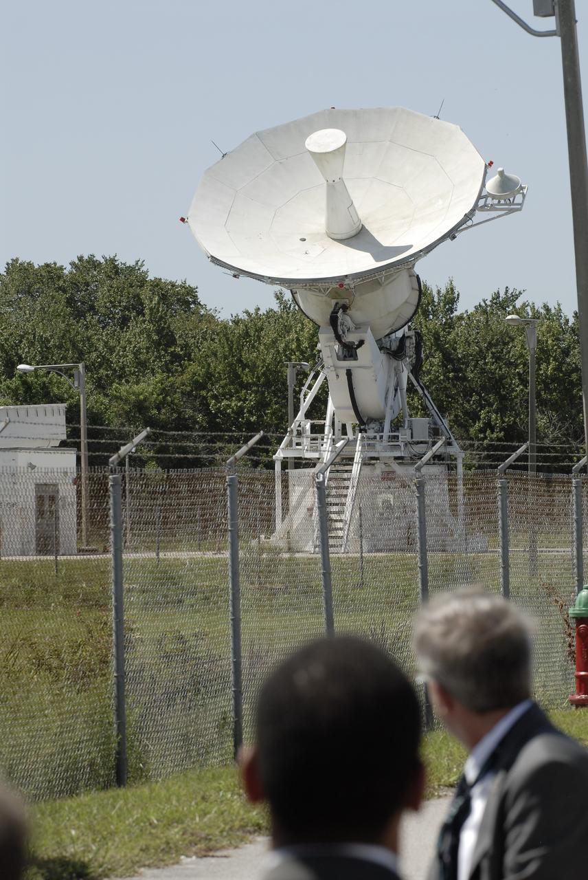
CAPE CANAVERAL, Fla. -- At the Merritt Island Launch Annex (MILA) Spaceflight Tracking and Data Network Station at NASA's Kennedy Space Center in Florida, one of two signature 30-foot steerable S-band antennas is slewed from the horizontal to the vertical position for the last time during a closing ceremony recognizing the station's 45 years of service. The antenna was pointed at Kennedy's Shuttle Landing Facility as it was for its last assignment, support of the landing of space shuttle Atlantis, concluding the STS-135 mission. STS-135 was the final mission of the Space Shuttle Program. The station was originally established by NASA's Goddard Space Flight Center as one of 17 Space Flight Tracking and Data Network stations around the world. Commissioned for the Apollo Program, the first launch it supported was the Apollo/Saturn 203 test flight from Launch Complex 37 on July 5, 1966. It also provided orbital support for low earth-orbiting scientific satellites. In recent history, the station has been used almost exclusively for space shuttle launch and landing support. Following the final launch and landing of the Space Shuttle Program in July 2011, the MILA station is officially decommissioned. For more information, visit http://www.nasa.gov/centers/kennedy/pdf/167424main_MILA-08C.pdf. Photo credit: NASA/Kim Shiflett

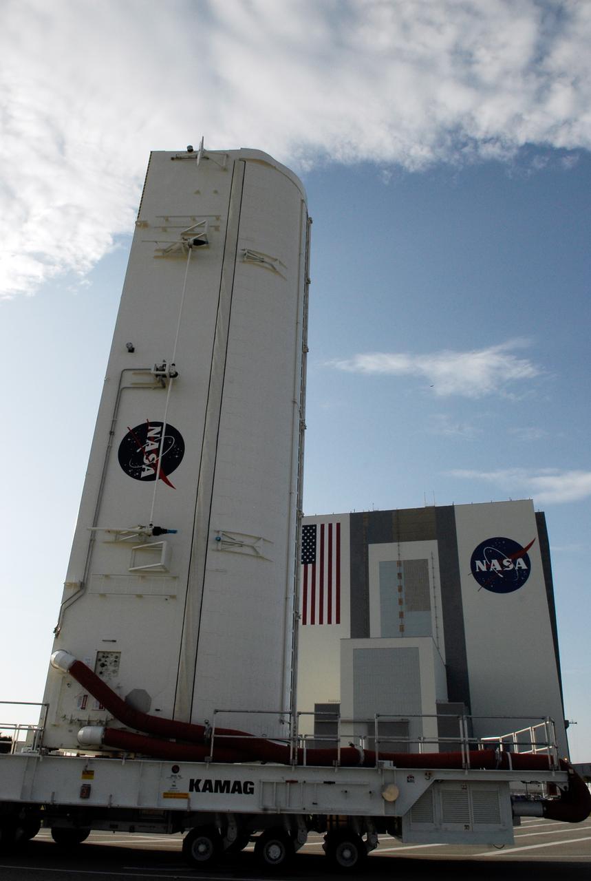
CAPE CANAVERAL, Fla. – Positioned on its 12-wheeled, 24-tire transporter, the payload canister with the STS-124 mission payload, Japanese Experiment Module - Pressurized Module and the Japanese Remote Manipulator System, or RMS, inside, backs out of the Vertical Integration Facility at NASA's Kennedy Space Center. The payload canister is being transported to Launch Pad 39A where the pressurized module and RMS will be lifted into the payload changeout room on the rotating service structure. The transporter is 65 feet long and 23 feet wide. The transporter’s wheels are independently steerable, permitting it to move forward, backward, sideways or diagonally and to turn on its own axis like a carousel. It is equipped with pneumatic-actuated braking and hydrostat¬ic leveling and drive systems. It is steered from a two-seat operator cab mounted at one end. From the payload changeout room, the pressurized module and RMS will be transferred into space shuttle Discovery’s payload bay. Launch is targeted for May 31. Photo credit: NASA/Kim Shiflett
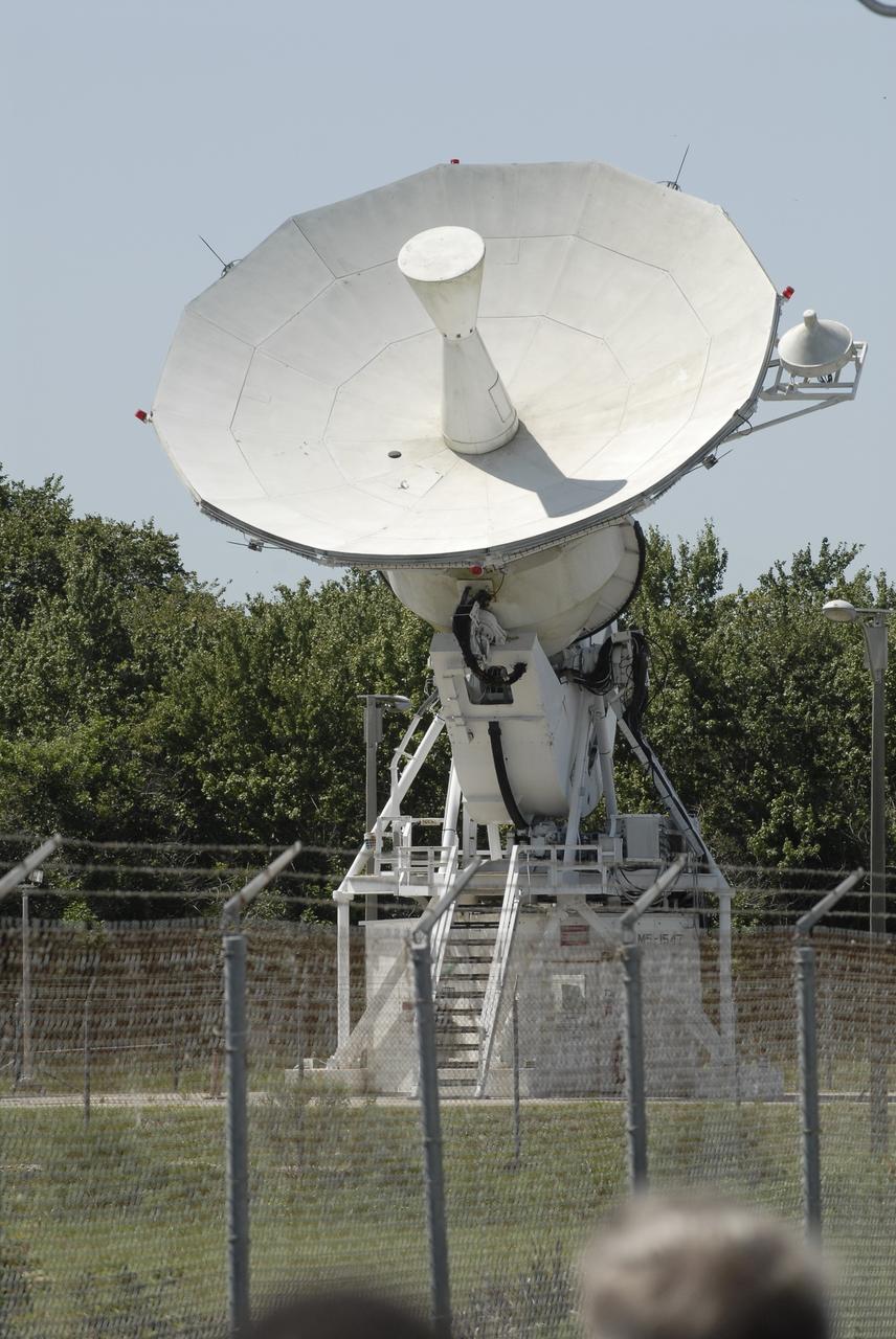
CAPE CANAVERAL, Fla. -- At the Merritt Island Launch Annex (MILA) Spaceflight Tracking and Data Network Station at NASA's Kennedy Space Center in Florida, one of two signature 30-foot steerable S-band antennas is slewed from the horizontal to the vertical position for the last time during a closing ceremony recognizing the station's 45 years of service. The antenna was pointed at Kennedy's Shuttle Landing Facility as it was for its last assignment, support of the landing of space shuttle Atlantis, concluding the STS-135 mission. STS-135 was the final mission of the Space Shuttle Program. The station was originally established by NASA's Goddard Space Flight Center as one of 17 Space Flight Tracking and Data Network stations around the world. Commissioned for the Apollo Program, the first launch it supported was the Apollo/Saturn 203 test flight from Launch Complex 37 on July 5, 1966. It also provided orbital support for low earth-orbiting scientific satellites. In recent history, the station has been used almost exclusively for space shuttle launch and landing support. Following the final launch and landing of the Space Shuttle Program in July 2011, the MILA station is officially decommissioned. For more information, visit http://www.nasa.gov/centers/kennedy/pdf/167424main_MILA-08C.pdf. Photo credit: NASA/Kim Shiflett