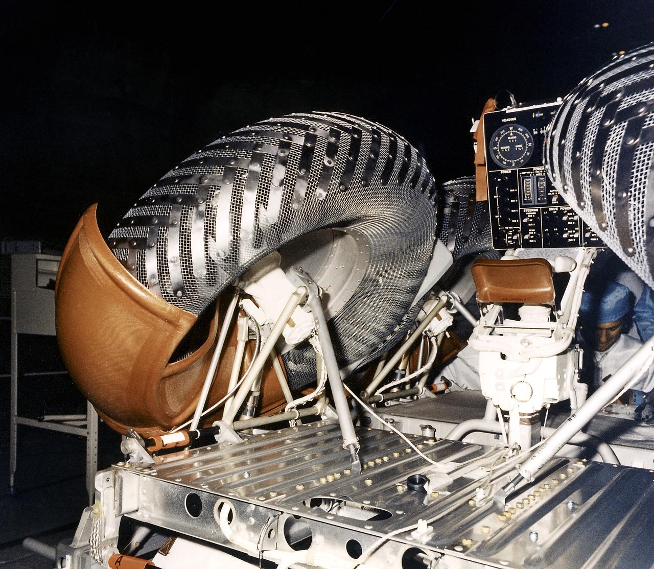
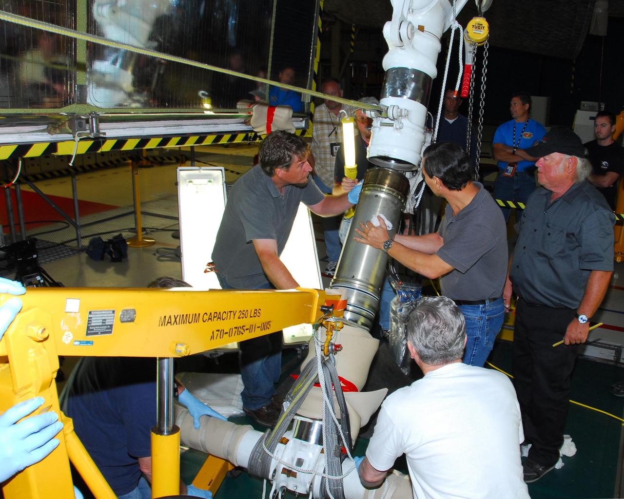
This is a close-up view of a right rear wheel strut of the Lunar Roving Vehicle (LRV) No. 1. The LRV was built to give Apollo astronauts a greater range of mobility during lunar exploration. It was an open-space and collapsible vehicle about 10 feet long with large mesh wheels, anterna, appendages, tool caddies, and camera. An LRV was used on each of the last three Apollo missions; Apollo 15, Apollo 16, and Apollo 17. It was built by the Boeing Company under the direction of the Marshall Space Flight Center.
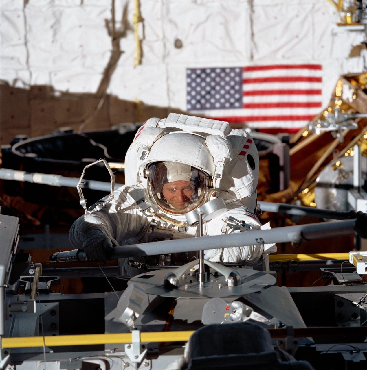
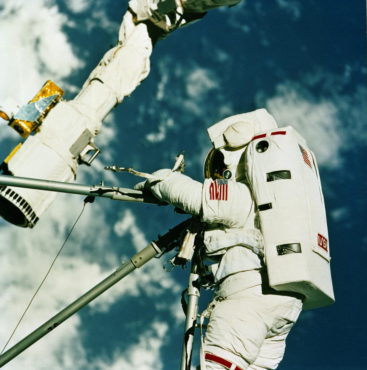
STS049-77-028 (14 May 1992) --- Astronaut Thomas D. Akers, STS-49 mission specialist, grabs a strut device as fourth period of extravehicular activity (EVA) gets underway in the Space Shuttle Endeavour's cargo bay. Akers is positioned near the Multi-purpose Support Structure (MPESS). The purpose of the final EVA on this nine-day mission was the evaluation of Assembly of Station by EVA Methods (ASEM). The scene was recorded on 70mm film by a fellow crew member in the space shuttle's cabin. Astronaut Kathryn C. Thornton (out of frame) joined Akers on the 7 1/2 hour EVA.
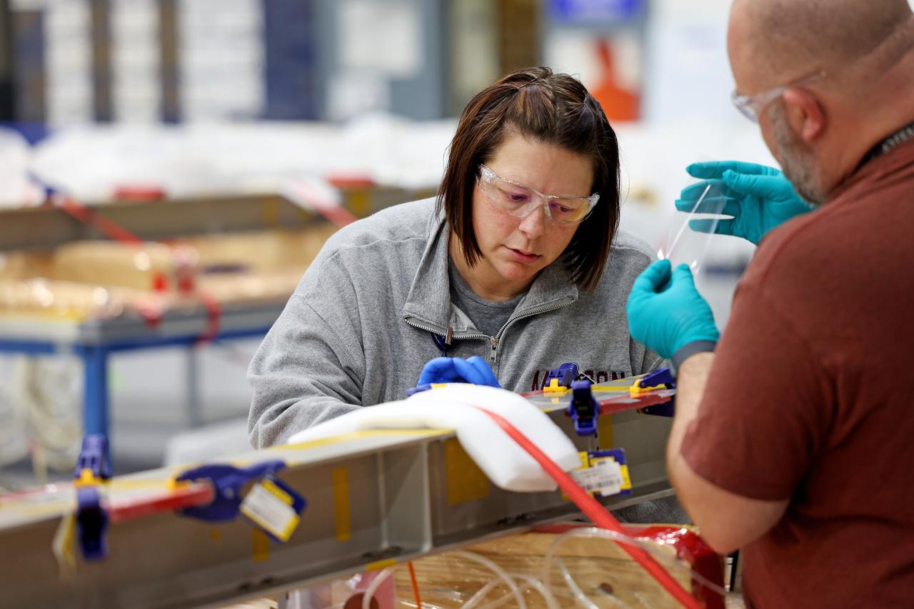
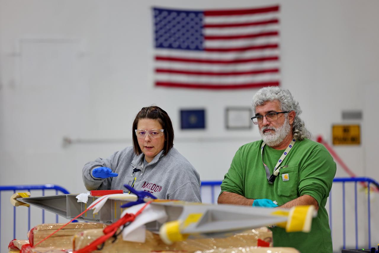
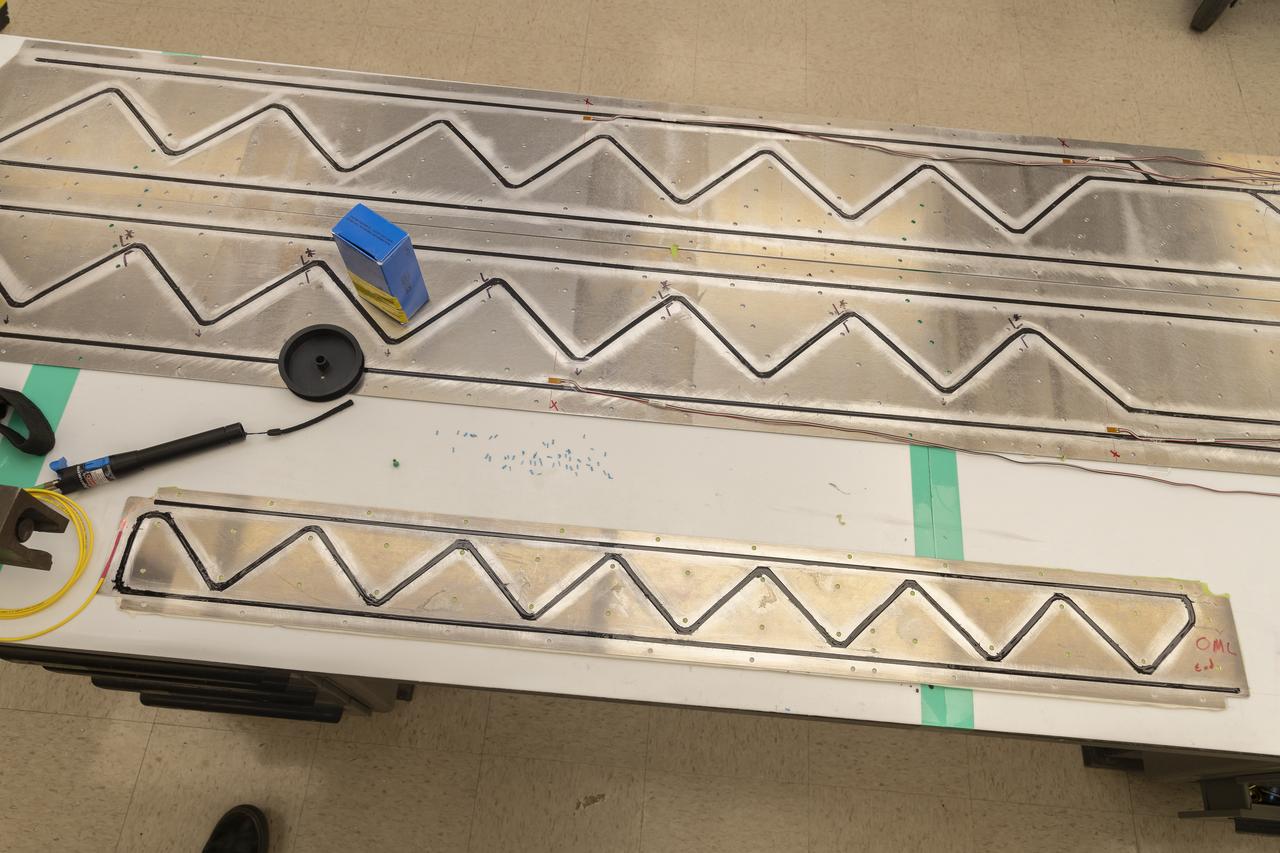
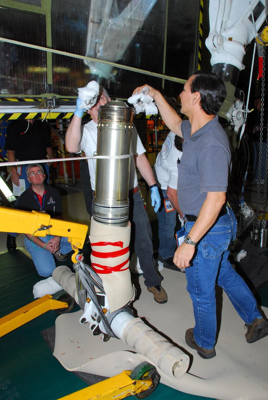
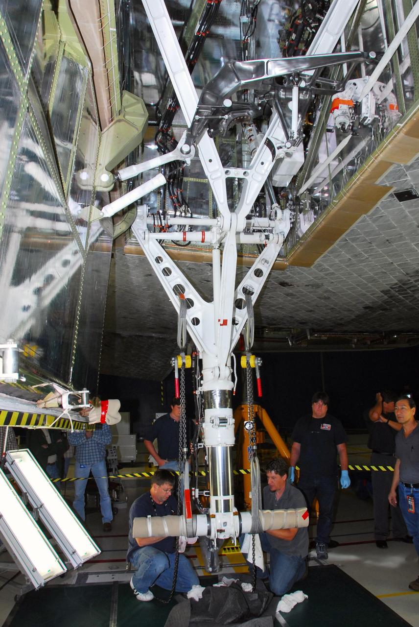
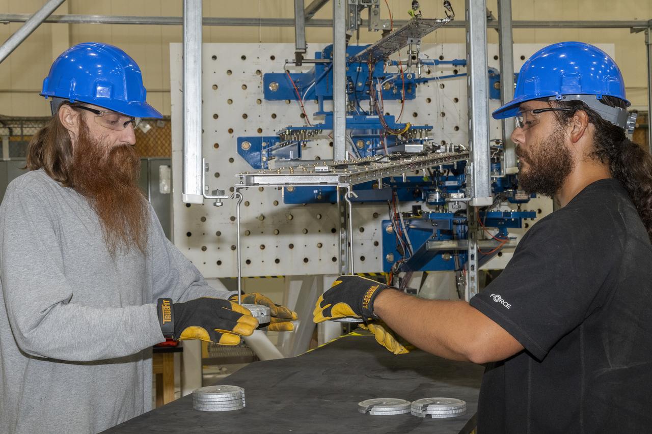
Technicians at NASA’s Michoud Assembly Facility in New Orleans on Feb. 22 prepare elements that will form part of the midbody for the future exploration upper stage for the SLS (Space Launch System) rocket. The midbody struts, or V-struts, will create the midbody’s cage-like outer structure to connect the upper stage’s larger liquid hydrogen tank to its smaller liquid oxygen tank. Manufacturing flight and test hardware for the future SLS upper stage is a collaborative effort between NASA and Boeing, the lead contractor for EUS and the SLS core stage. Beginning with Artemis IV, SLS will evolve to its more powerful Block 1B configuration with the advanced exploration upper stage that gives the rocket the capability to launch 40% more to the Moon along with Artemis astronauts inside NASA’s Orion spacecraft. The evolved in-space stage for SLS will use a combination of liquid oxygen and liquid hydrogen propellants to help power the engines to send large cargo and crew inside Orion to the Moon. Image credit: NASA/Michael DeMocker
Technicians at NASA’s Michoud Assembly Facility in New Orleans on Feb. 22 prepare elements that will form part of the midbody for the future exploration upper stage for the SLS (Space Launch System) rocket. The midbody struts, or V-struts, will create the midbody’s cage-like outer structure to connect the upper stage’s larger liquid hydrogen tank to its smaller liquid oxygen tank. Manufacturing flight and test hardware for the future SLS upper stage is a collaborative effort between NASA and Boeing, the lead contractor for EUS and the SLS core stage. Beginning with Artemis IV, SLS will evolve to its more powerful Block 1B configuration with the advanced exploration upper stage that gives the rocket the capability to launch 40% more to the Moon along with Artemis astronauts inside NASA’s Orion spacecraft. The evolved in-space stage for SLS will use a combination of liquid oxygen and liquid hydrogen propellants to help power the engines to send large cargo and crew inside Orion to the Moon. Image credit: NASA/Michael DeMocker

Technicians at NASA’s Michoud Assembly Facility in New Orleans on Feb. 22 prepare elements that will form part of the midbody for the future exploration upper stage for the SLS (Space Launch System) rocket. The midbody struts, or V-struts, will create the midbody’s cage-like outer structure to connect the upper stage’s larger liquid hydrogen tank to its smaller liquid oxygen tank. Manufacturing flight and test hardware for the future SLS upper stage is a collaborative effort between NASA and Boeing, the lead contractor for EUS and the SLS core stage. Beginning with Artemis IV, SLS will evolve to its more powerful Block 1B configuration with the advanced exploration upper stage that gives the rocket the capability to launch 40% more to the Moon along with Artemis astronauts inside NASA’s Orion spacecraft. The evolved in-space stage for SLS will use a combination of liquid oxygen and liquid hydrogen propellants to help power the engines to send large cargo and crew inside Orion to the Moon. Image credit: NASA/Michael DeMocker
Instrumentation of the wing and strut that comprise the Mock Truss-Braced Wing 10-foot model are complete at NASA’s Armstrong Flight Research Center in Edwards, California.
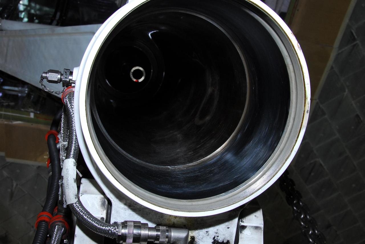
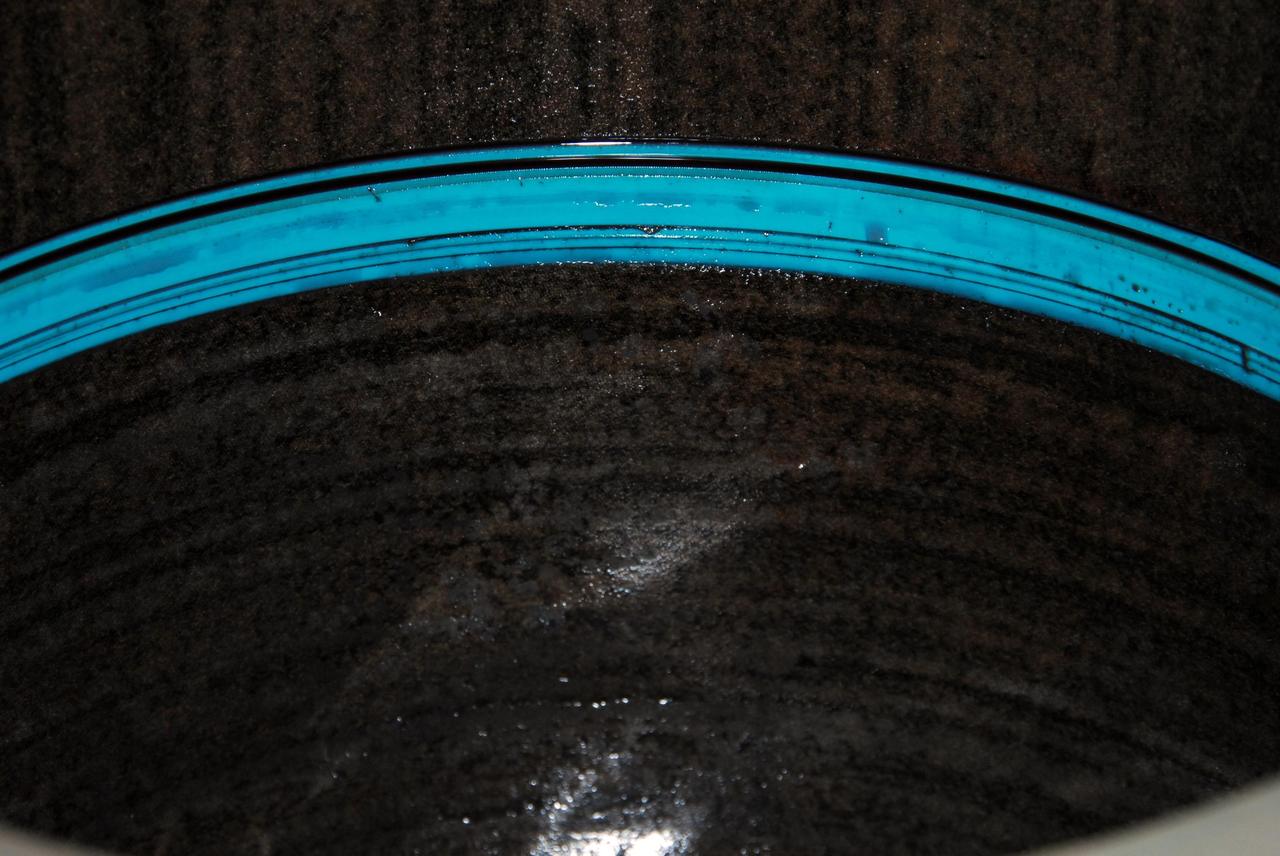
KENNEDY SPACE CENTER, FLA. -- This photo looks inside space shuttle Discovery's right main-gear strut where a leaking seal has been found. United Space Alliance and B.F. Goodrich technicians will replace a leaking dynamic seal in Discovery's right main-gear strut. The struts act as shock absorbers during the shuttle's landing. Engineers determined the observed leak of hydraulic fluid in the main landing gear strut exceeded specification and could not be reduced to an acceptable rate. Removing the strut and replacing seals require disconnecting and replacing the brakes and tires, disconnecting and reconnecting instruments and other requirements to allow access to the strut. Discovery had been scheduled to roll over Sept. 19 from its processing hangar to the Vehicle Assembly Building. A new rollover date will be set after technicians determine how long replacing the seal will take. Photo credit: NASA/George Shelton
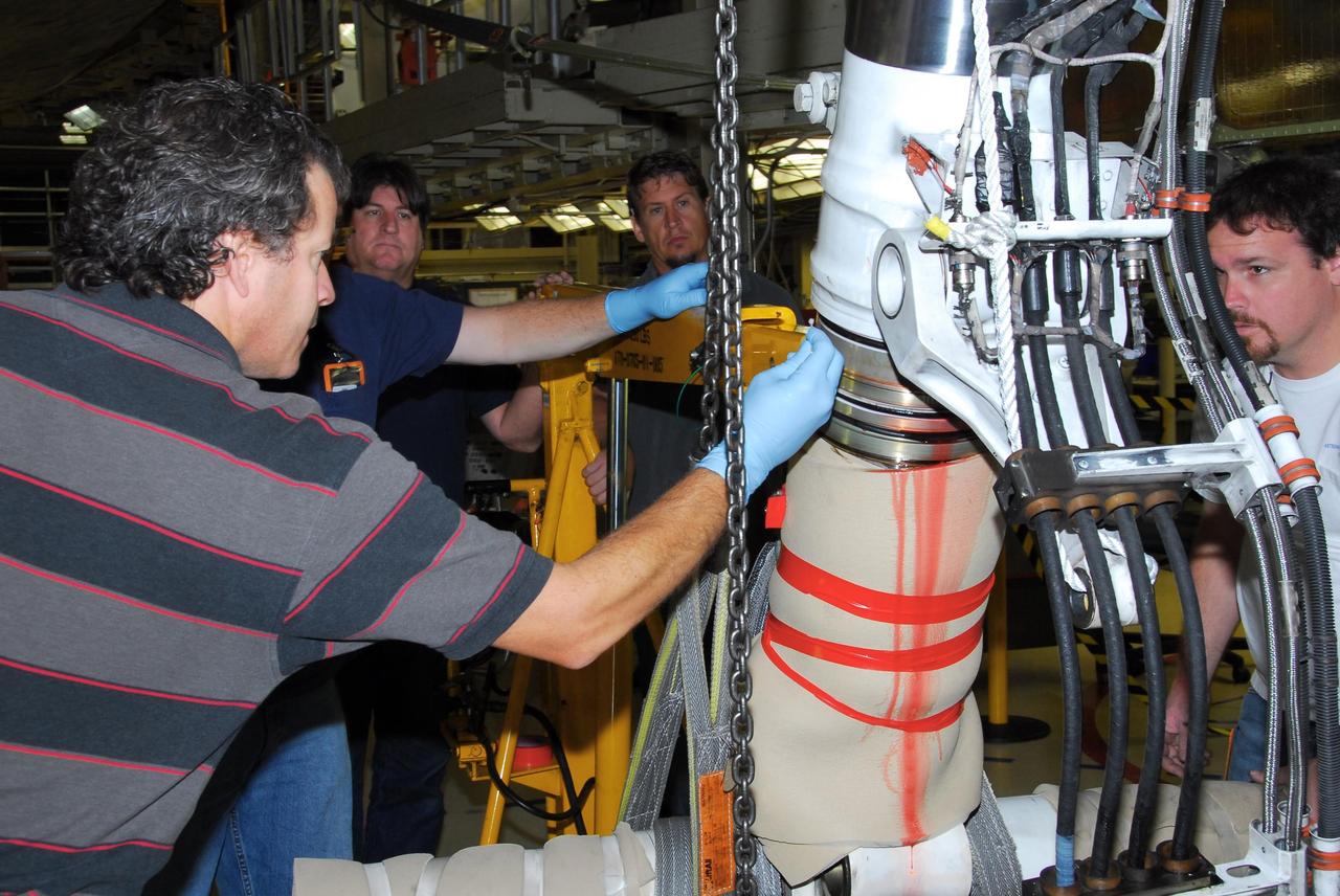
KENNEDY SPACE CENTER, FLA. -- In Orbiter Processing Facility bay 3, United Space Alliance and B.F. Goodrich technicians begin work on the starboard landing gear assembly of space shuttle Discovery. They will replace a leaking dynamic seal in Discovery's right main-gear strut. The struts act as shock absorbers during the shuttle's landing. Engineers determined the observed leak of hydraulic fluid in the main landing gear strut exceeded specification and could not be reduced to an acceptable rate. Removing the strut and replacing seals require disconnecting and replacing the brakes and tires, disconnecting and reconnecting instruments and other requirements to allow access to the strut. Discovery had been scheduled to roll over Sept. 19 from its processing hangar to the Vehicle Assembly Building. A new rollover date will be set after technicians determine how long replacing the seal will take. Photo credit: NASA/George Shelton
KENNEDY SPACE CENTER, FLA. -- This photo looks inside space shuttle Discovery's right main-gear strut where a leaking seal has been found. United Space Alliance and B.F. Goodrich technicians will replace the seal. The struts act as shock absorbers during the shuttle's landing. Engineers determined the observed leak of hydraulic fluid in the main landing gear strut exceeded specification and could not be reduced to an acceptable rate. Removing the strut and replacing seals require disconnecting and replacing the brakes and tires, disconnecting and reconnecting instruments and other requirements to allow access to the strut. Discovery had been scheduled to roll over Sept. 19 from its processing hangar to the Vehicle Assembly Building. A new rollover date will be set after technicians determine how long replacing the seal will take. Photo credit: NASA/George Shelton
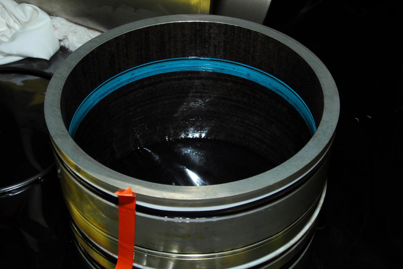
KENNEDY SPACE CENTER, FLA. -- This photo reveals the area of a seal on space shuttle Discovery's right main-gear strut that was determined to be leaking. United Space Alliance and B.F. Goodrich technicians are replacing the seal. The struts act as shock absorbers during the shuttle's landing. Engineers determined the observed leak of hydraulic fluid in the main landing gear strut exceeded specification and could not be reduced to an acceptable rate. Removing the strut and replacing seals require disconnecting and replacing the brakes and tires, disconnecting and reconnecting instruments and other requirements to allow access to the strut. Discovery had been scheduled to roll over Sept. 19 from its processing hangar to the Vehicle Assembly Building. A new rollover date will be set after technicians determine how long replacing the seal will take. Photo credit: NASA/George Shelton
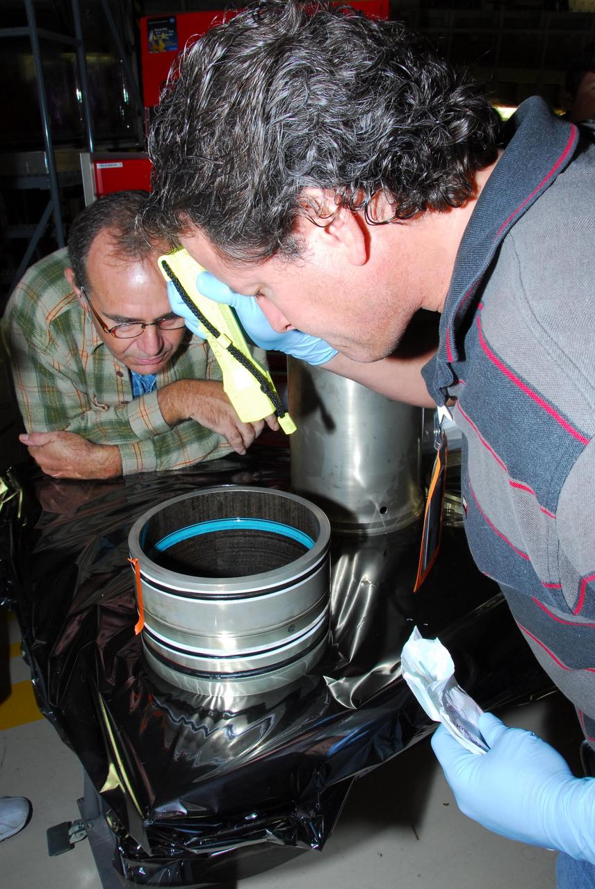
KENNEDY SPACE CENTER, FLA. -- In Orbiter Processing Facility bay 3, United Space Alliance and B.F. Goodrich technicians look inside part of space shuttle Discovery's right main-gear strut where a leaking seal has been found. The struts act as shock absorbers during the shuttle's landing. The seal will be replaced. Engineers determined the observed leak of hydraulic fluid in the main landing gear strut exceeded specification and could not be reduced to an acceptable rate. Removing the strut and replacing seals require disconnecting and replacing the brakes and tires, disconnecting and reconnecting instruments and other requirements to allow access to the strut. Discovery had been scheduled to roll over Sept. 19 from its processing hangar to the Vehicle Assembly Building. A new rollover date will be set after technicians determine how long replacing the seal will take. Photo credit: NASA/George Shelton
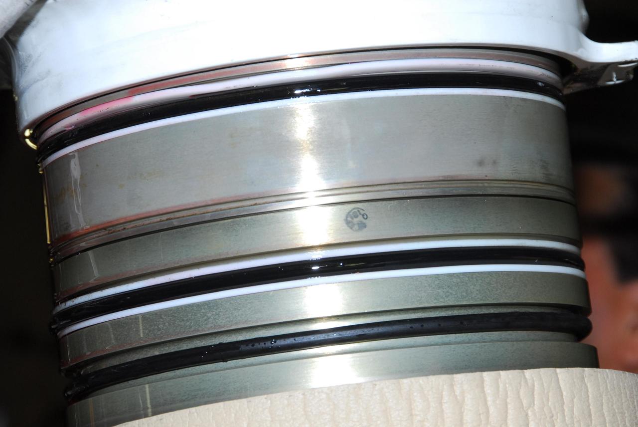
KENNEDY SPACE CENTER, FLA. -- This photo shows the leaking hydraulic seal in space shuttle Discovery's right main-gear strut. United Space Alliance and B.F. Goodrich technicians are working to replace the seal. The struts act as shock absorbers during the shuttle's landing. Engineers determined the observed leak of hydraulic fluid in the main landing gear strut exceeded specification and could not be reduced to an acceptable rate. Removing the strut and replacing seals require disconnecting and replacing the brakes and tires, disconnecting and reconnecting instruments and other requirements to allow access to the strut. Discovery had been scheduled to roll over Sept. 19 from its processing hangar to the Vehicle Assembly Building. A new rollover date will be set after technicians determine how long replacing the seal will take. Photo credit: NASA/George Shelton
KENNEDY SPACE CENTER, FLA. -- In Orbiter Processing Facility bay 3, United Space Alliance and B.F. Goodrich technicians work on the starboard landing gear assembly of space shuttle Discovery. They will replace a leaking dynamic seal in Discovery's right main-gear strut. The struts act as shock absorbers during the shuttle's landing. Engineers determined the observed leak of hydraulic fluid in the main landing gear strut exceeded specification and could not be reduced to an acceptable rate. Removing the strut and replacing seals require disconnecting and replacing the brakes and tires, disconnecting and reconnecting instruments and other requirements to allow access to the strut. Discovery had been scheduled to roll over Sept. 19 from its processing hangar to the Vehicle Assembly Building. A new rollover date will be set after technicians determine how long replacing the seal will take. Photo credit: NASA/George Shelton

KENNEDY SPACE CENTER, FLA. -- In Orbiter Processing Facility bay 3, United Space Alliance and B.F. Goodrich technicians begin work on the starboard landing gear assembly of space shuttle Discovery. They will replace a leaking dynamic seal in Discovery's right main-gear strut. The struts act as shock absorbers during the shuttle's landing. Engineers determined the observed leak of hydraulic fluid in the main landing gear strut exceeded specification and could not be reduced to an acceptable rate. Removing the strut and replacing seals require disconnecting and replacing the brakes and tires, disconnecting and reconnecting instruments and other requirements to allow access to the strut. Discovery had been scheduled to roll over Sept. 19 from its processing hangar to the Vehicle Assembly Building. A new rollover date will be set after technicians determine how long replacing the seal will take. Photo credit: NASA/George Shelton
KENNEDY SPACE CENTER, FLA. -- In Orbiter Processing Facility bay 3, United Space Alliance and B.F. Goodrich technicians work on the starboard landing gear assembly of space shuttle Discovery. They will replace a leaking dynamic seal in Discovery's right main-gear strut. The struts act as shock absorbers during the shuttle's landing. Engineers determined the observed leak of hydraulic fluid in the main landing gear strut exceeded specification and could not be reduced to an acceptable rate. Removing the strut and replacing seals require disconnecting and replacing the brakes and tires, disconnecting and reconnecting instruments and other requirements to allow access to the strut. Discovery had been scheduled to roll over Sept. 19 from its processing hangar to the Vehicle Assembly Building. A new rollover date will be set after technicians determine how long replacing the seal will take. Photo credit: NASA/George Shelton

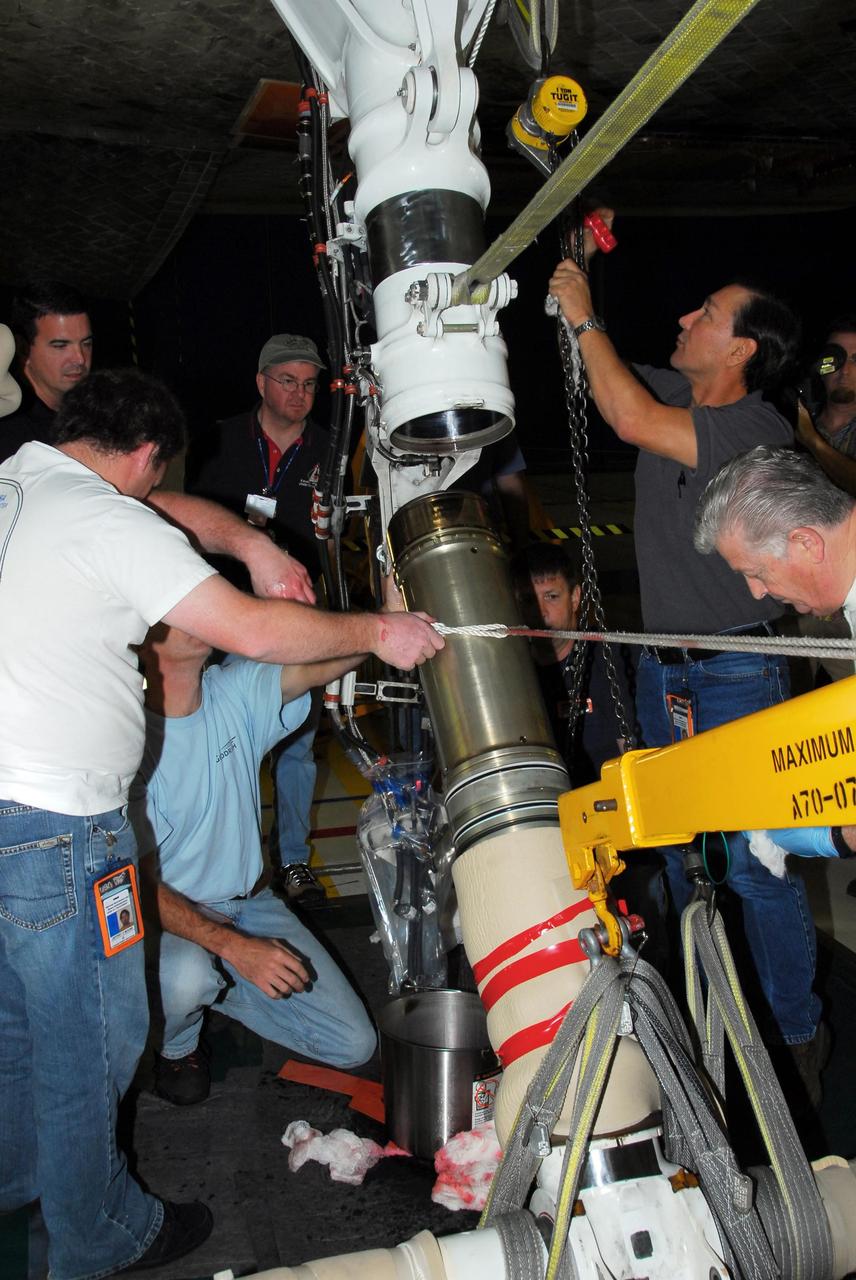
KENNEDY SPACE CENTER, FLA. -- In Orbiter Processing Facility bay 3, United Space Alliance and B.F. Goodrich technicians remove part of space shuttle Discovery's right main-gear strut where a leaking seal has been found. They will replace the seal. The struts act as shock absorbers during the shuttle's landing. Engineers determined the observed leak of hydraulic fluid in the main landing gear strut exceeded specification and could not be reduced to an acceptable rate. Removing the strut and replacing seals require disconnecting and replacing the brakes and tires, disconnecting and reconnecting instruments and other requirements to allow access to the strut. Discovery had been scheduled to roll over Sept. 19 from its processing hangar to the Vehicle Assembly Building. A new rollover date will be set after technicians determine how long replacing the seal will take. Photo credit: NASA/George Shelton
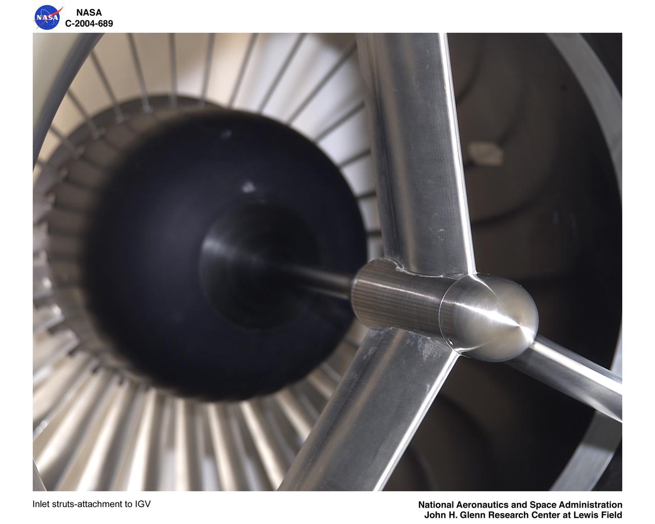
Inlet struts-attachment to Inlet Guide Vane

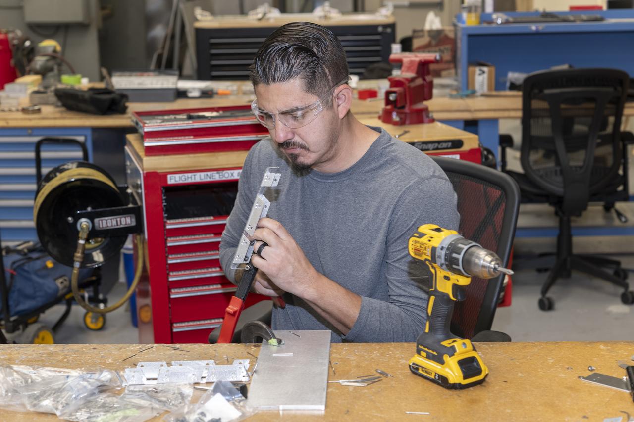
Matthew Sanchez attaches the strut and the wing to ensure they fit together as intended for a 10-foot model of the Transonic Truss-Braced Wing at NASA’s Armstrong Flight Research Center, in Edwards, California. The aircraft concept involves a wing braced on an aircraft using diagonal struts that also add lift and could result in significantly improved aerodynamics.
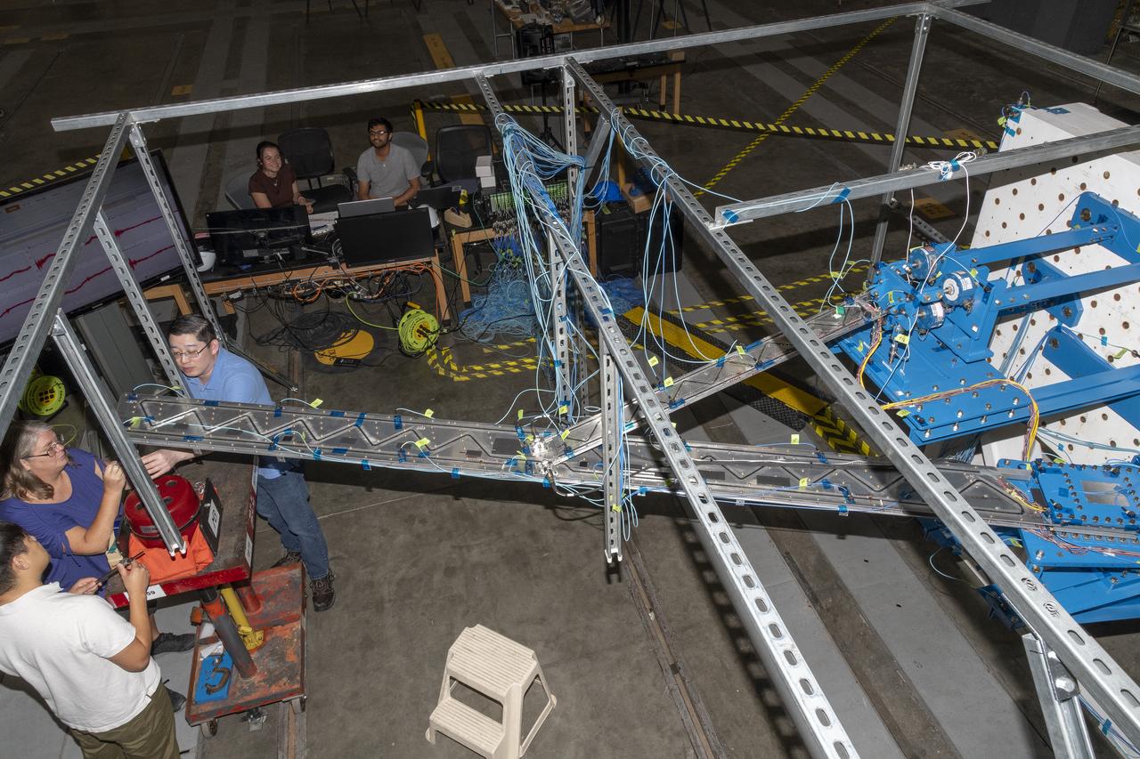
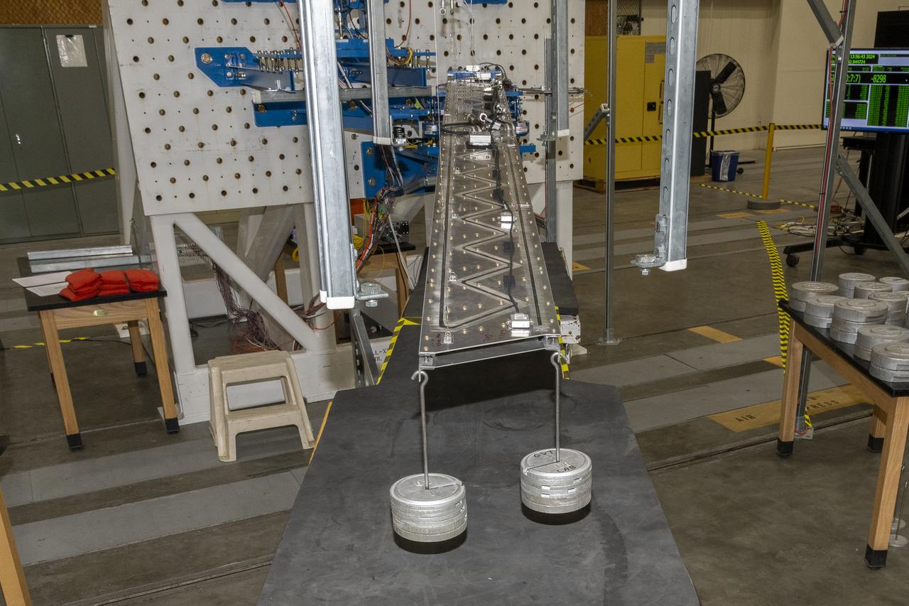
Researchers test a 10-foot Mock Truss-Braced Wing at NASA’s Armstrong Flight Research Center in Edwards, California. A view from above shows the test structure, the wing, and the strut. The aircraft concept involves a wing braced on an aircraft using diagonal struts that also add lift and could result in significantly improved aerodynamics.
A jury strut adaptor is created for a 10-foot model of the Transonic Truss-Braced Wing at NASA’s Armstrong Flight Research Center, in Edwards, California. The aircraft concept involves a wing braced on an aircraft using diagonal struts that also add lift and could result in significantly improved aerodynamics.
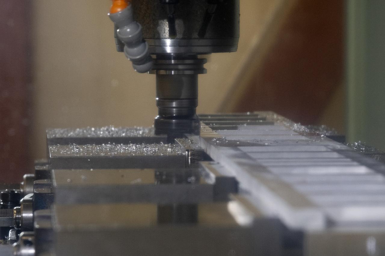
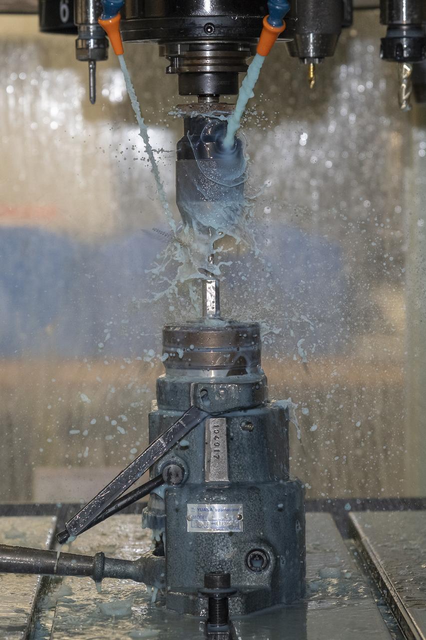
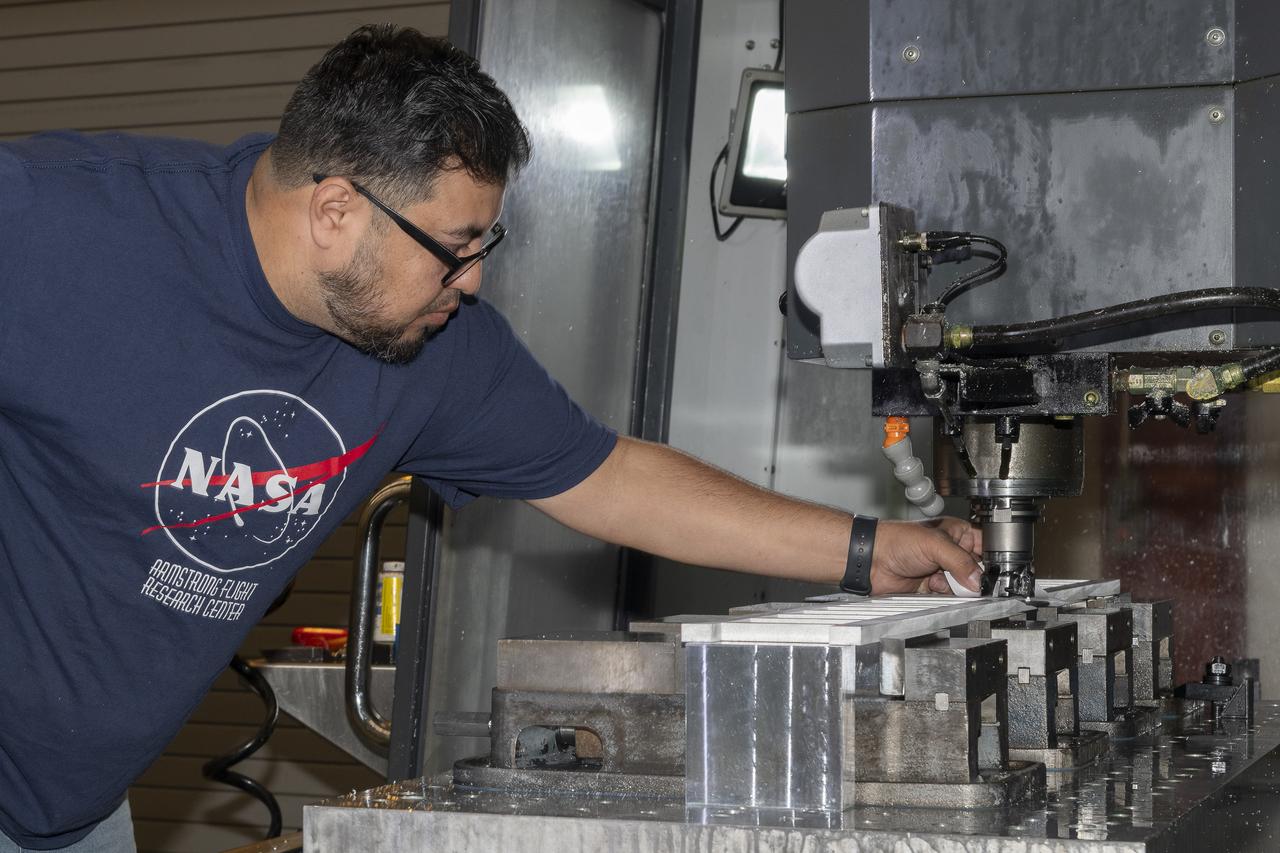
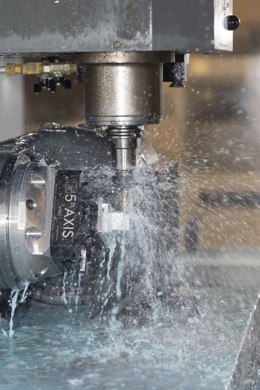
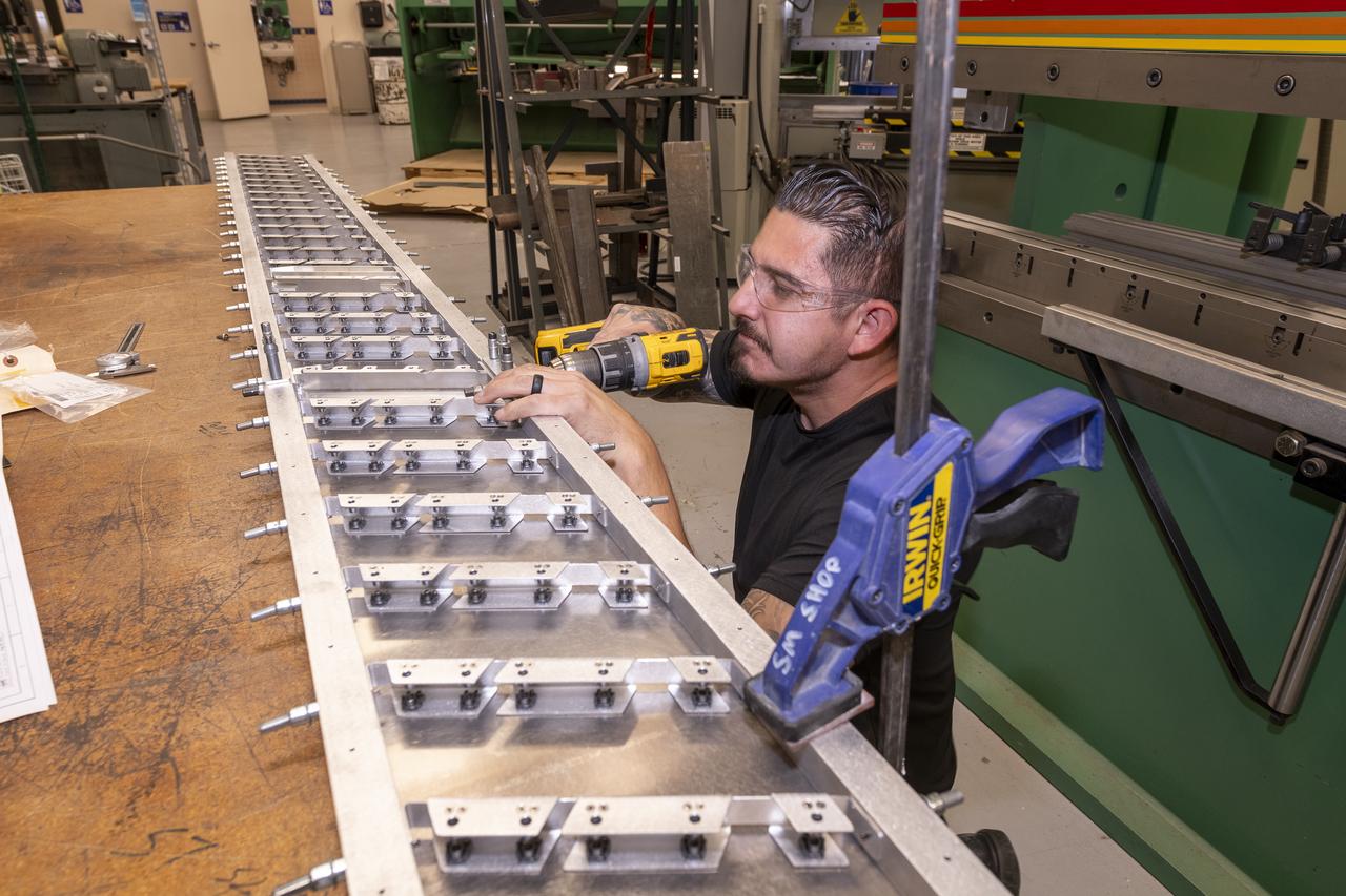
A milling machine drills holes in the strut frame assembly for a 10-foot model of the Transonic Truss-Braced Wing at NASA’s Armstrong Flight Research Center, in Edwards, California. The aircraft concept involves a wing braced on an aircraft using diagonal struts that also add lift and could result in significantly improved aerodynamics.
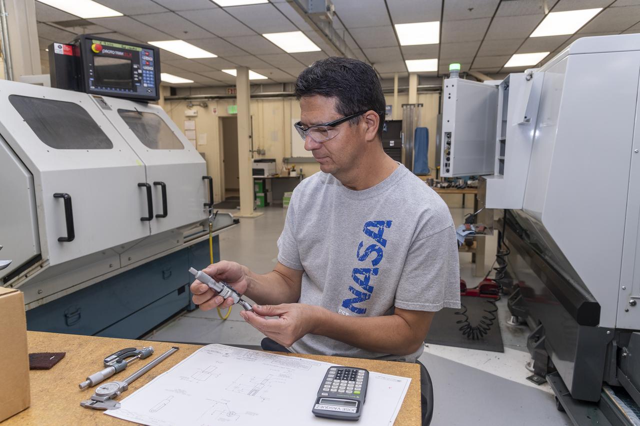
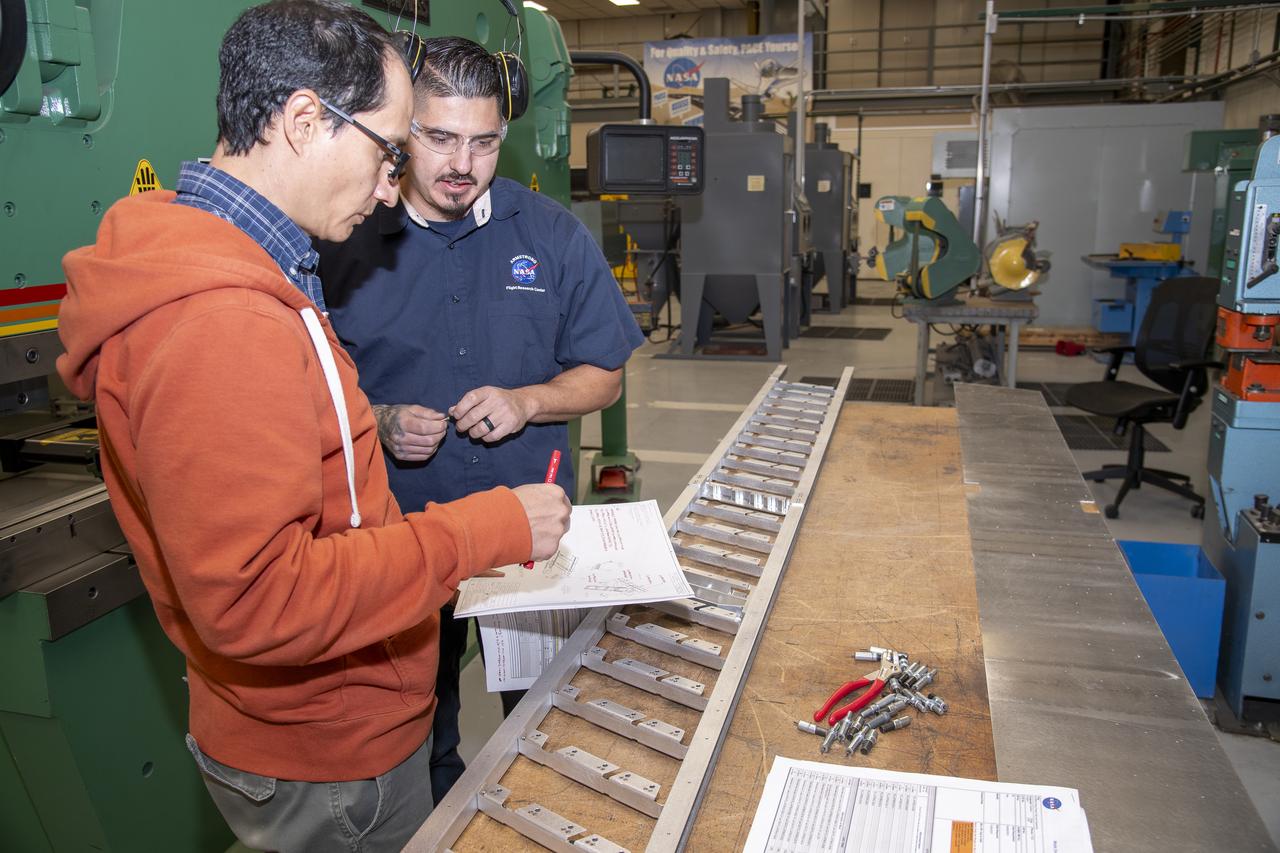
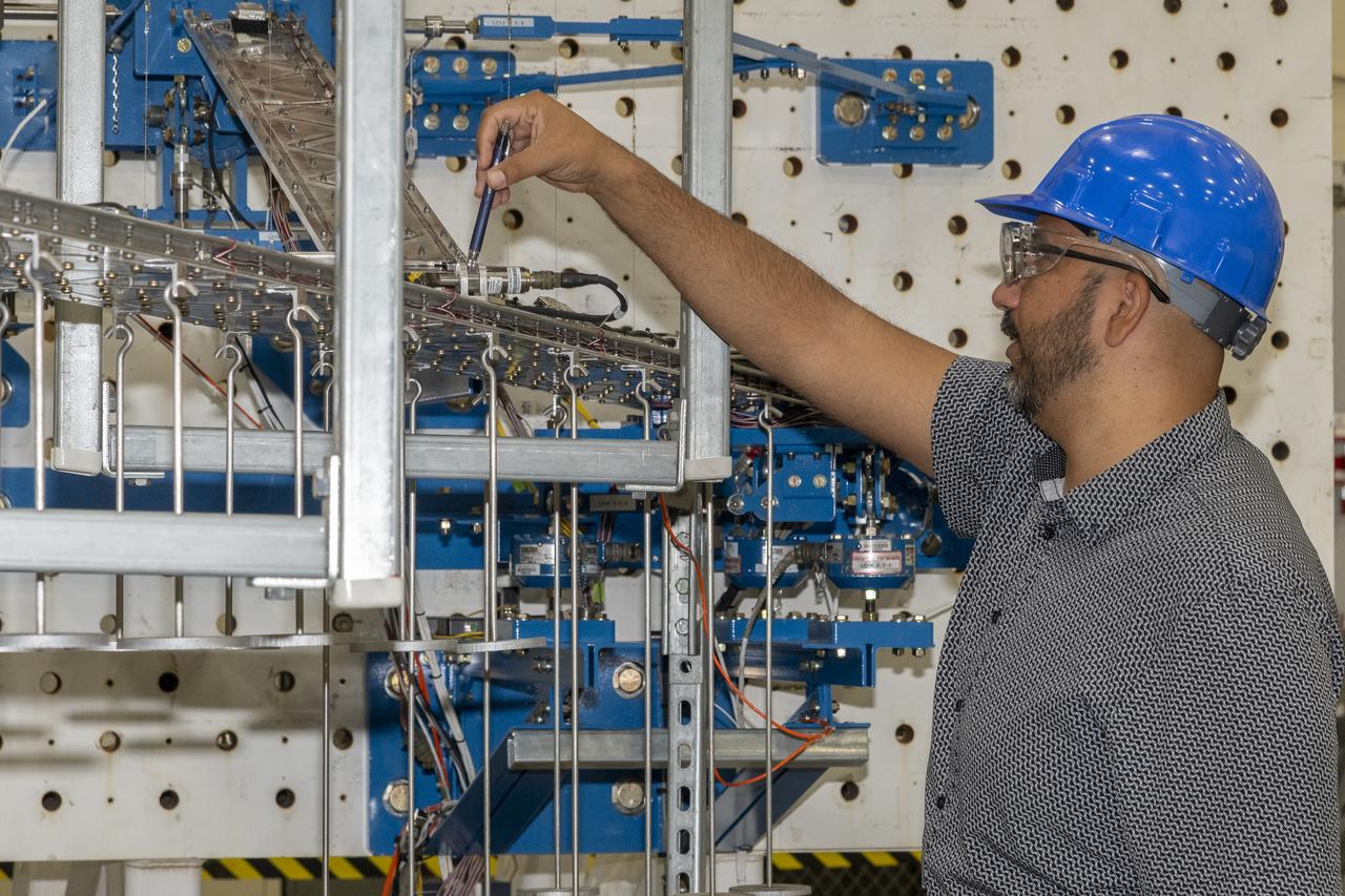
Jose Vasquez verifies a jury strut adaptor created for a 10-foot model of the Transonic Truss-Braced Wing at NASA’s Armstrong Flight Research Center, in Edwards, California. The aircraft concept involves a wing braced on an aircraft using diagonal struts that also add lift and could result in significantly improved aerodynamics.
Matthew Sanchez attaches the strut and the wing to ensure they fit together as intended for a 10-foot model of the Transonic Truss-Braced Wing at NASA’s Armstrong Flight Research Center, in Edwards, California. The aircraft concept involves a wing braced on an aircraft using diagonal struts that also add lift and could result in significantly improved aerodynamics.
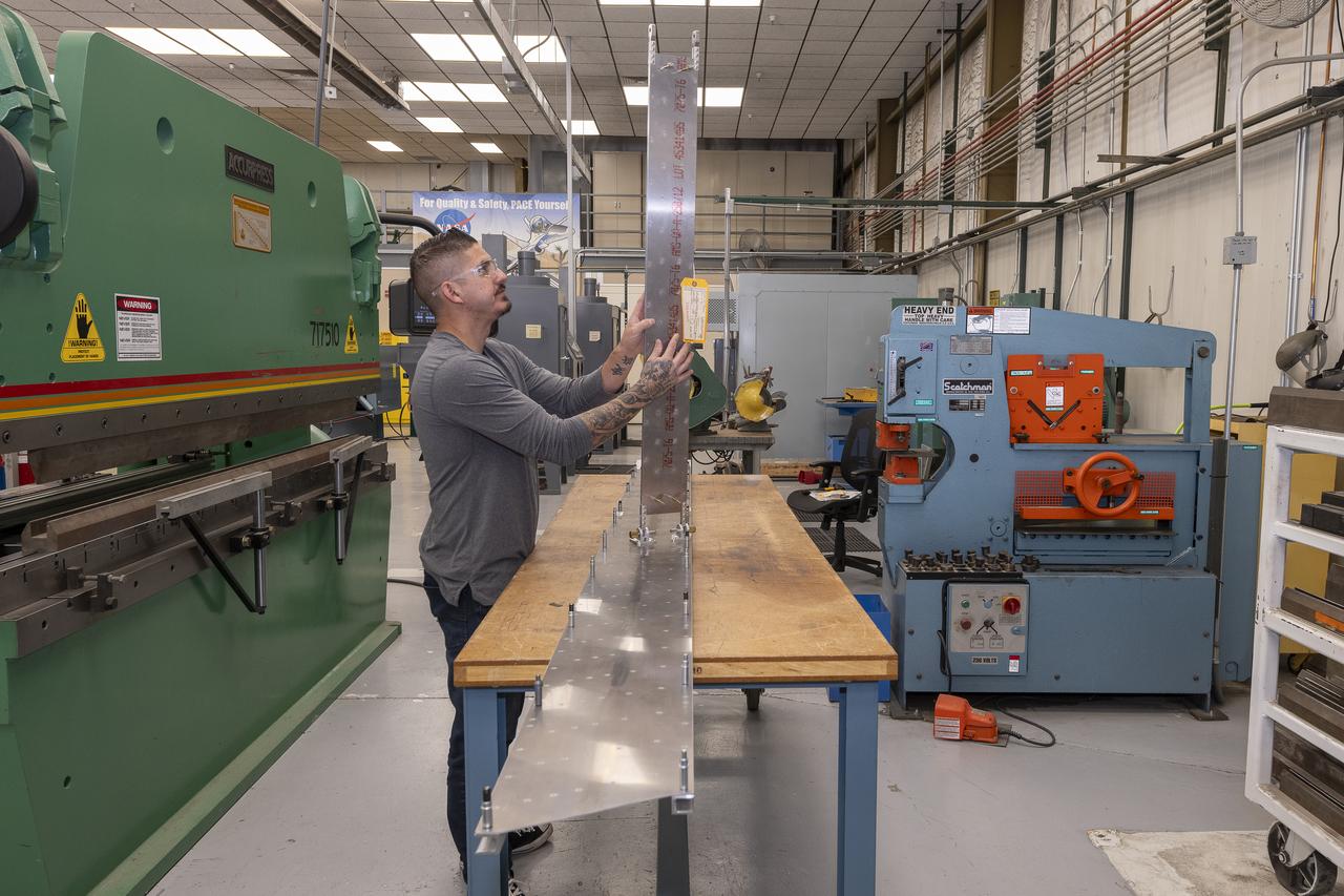
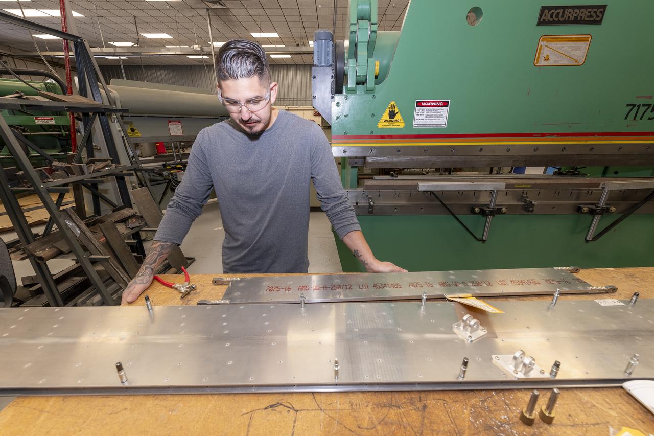
Matthew Sanchez prepares a sheet of aluminum that will be cut into the outer layer of the strut for the 10-foot model of the Transonic Truss-Braced Wing at NASA’s Armstrong Flight Research Center, in Edwards, California. The aircraft concept involves a wing braced on an aircraft using diagonal struts that also add lift and could result in significantly improved aerodynamics.
German Escobar works on milling the strut frame assembly for a 10-foot model of the Transonic Truss-Braced Wing at NASA’s Armstrong Flight Research Center, in Edwards, California. The aircraft concept involves a wing braced on an aircraft using diagonal struts that also add lift and could result in significantly improved aerodynamics.
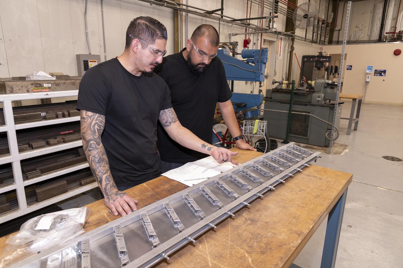
Matthew Sanchez consults with Andrew Holguin on the strut for a 10-foot model of the Transonic Truss-Braced Wing at NASA’s Armstrong Flight Research Center, in Edwards, California. The aircraft concept involves a wing braced on an aircraft using diagonal struts that also add lift and could result in significantly improved aerodynamics.
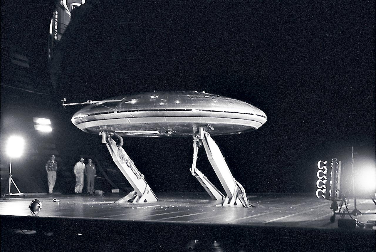
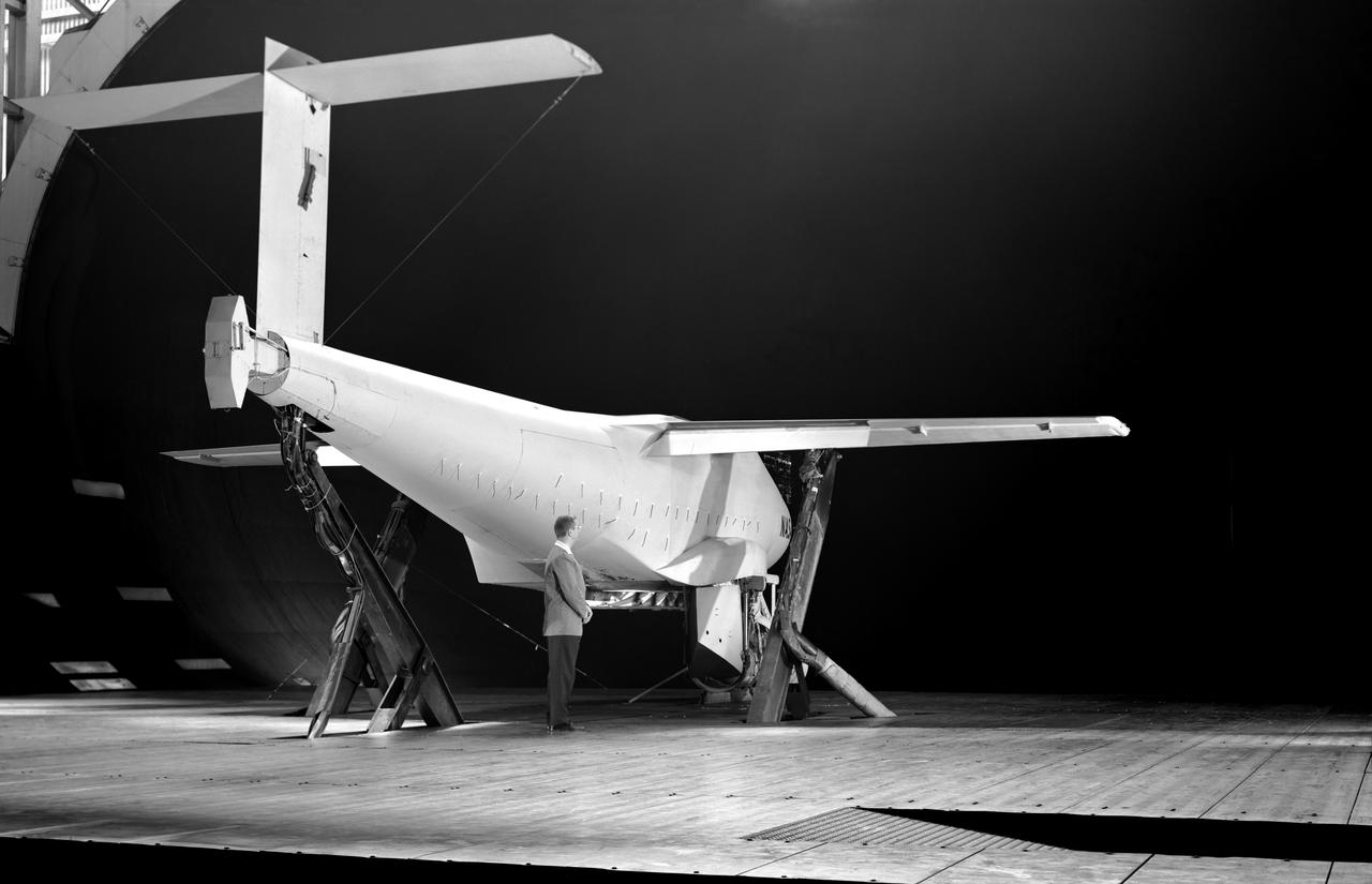
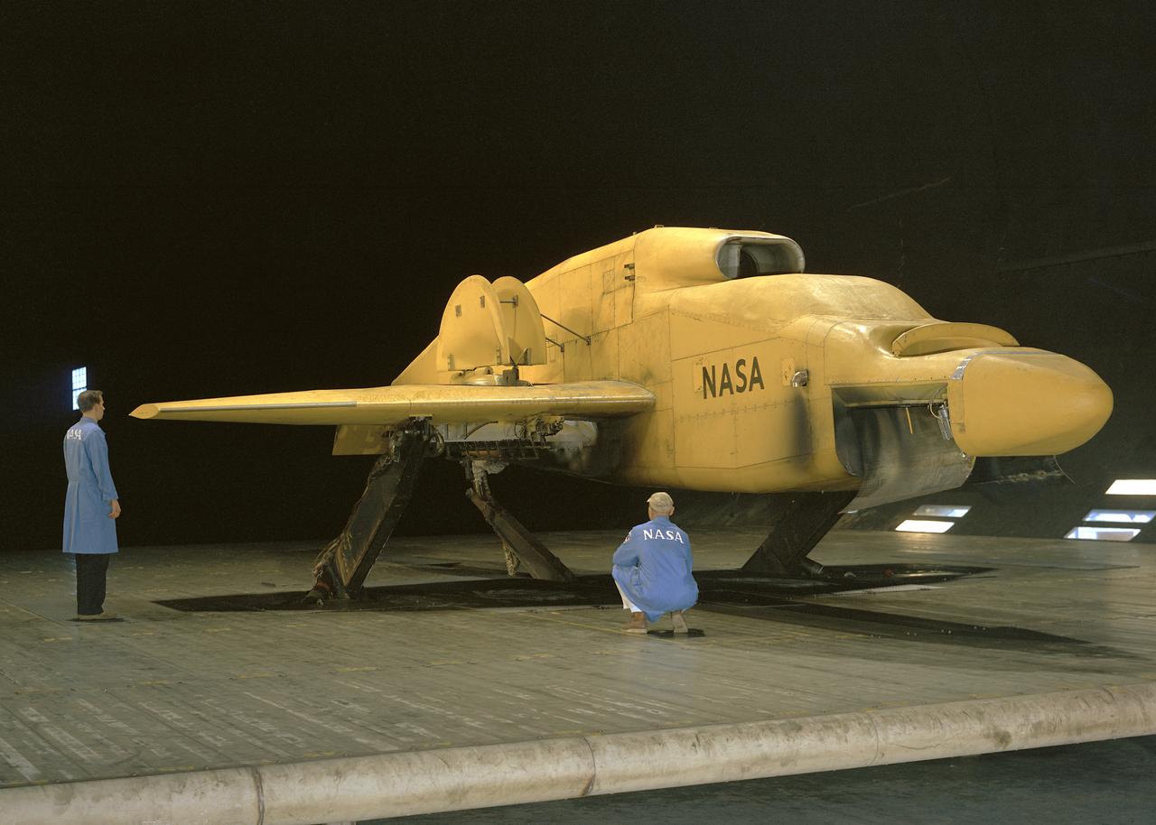
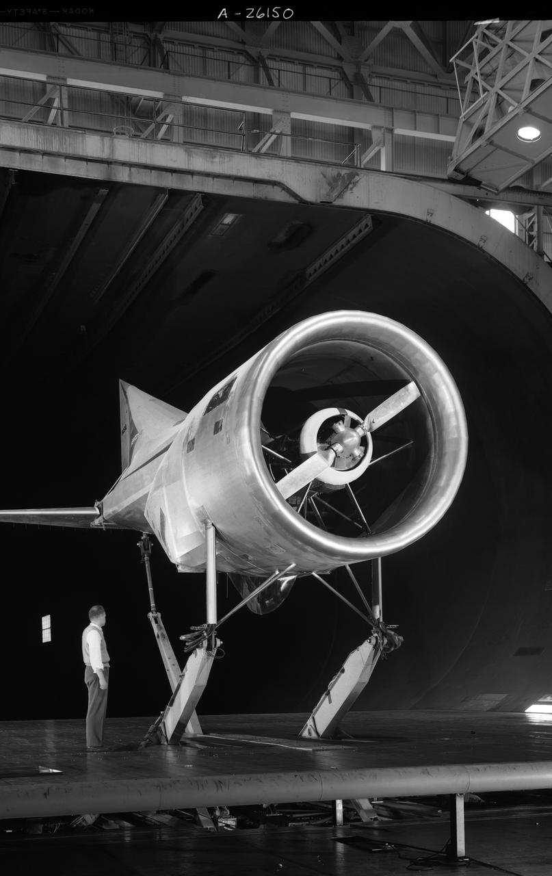
Front 3/4 view of the Avrocar mounted on variable height struts in the Ames 40x80 foot wind tunnel, without tail.
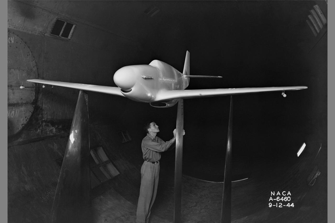
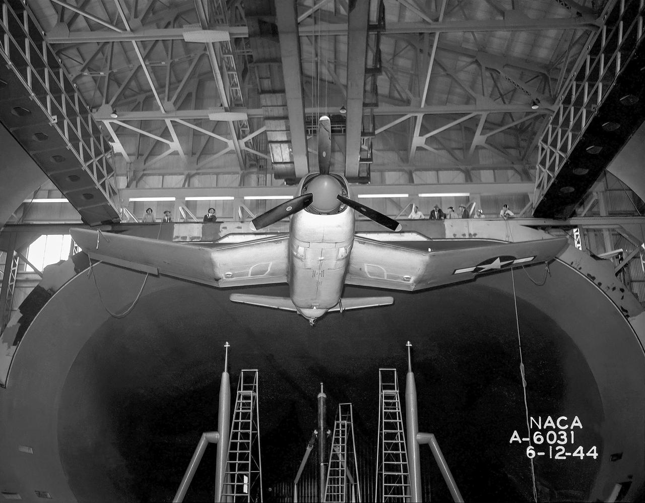
North American P-51B 1/3 scale model with dummy airspeed booms & mounted on thin struts in 16ft w.t.
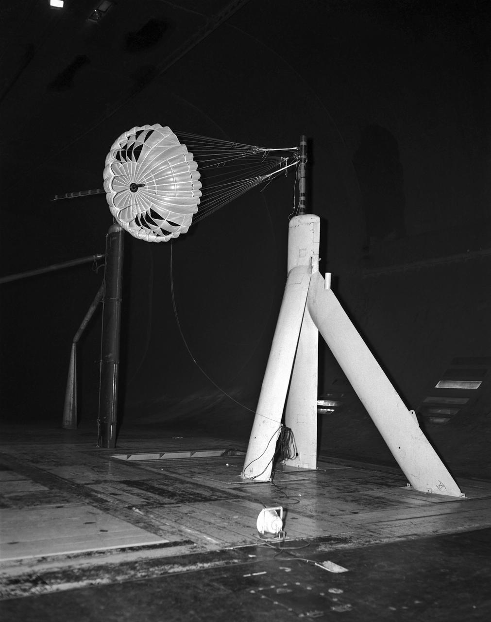
Gliding parachute test in 40x80 foot Wind Tunnel, mounted on main strut flying horizontally.
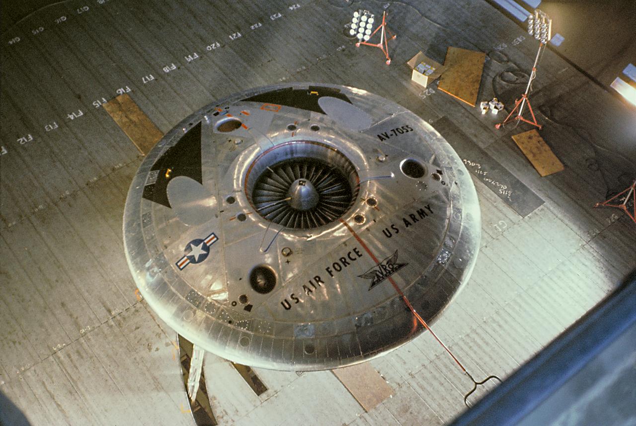
Color view of the Avrocar from overhead in the 40x80 wind tunnel, without A1:H73 mounted on variable height struts.
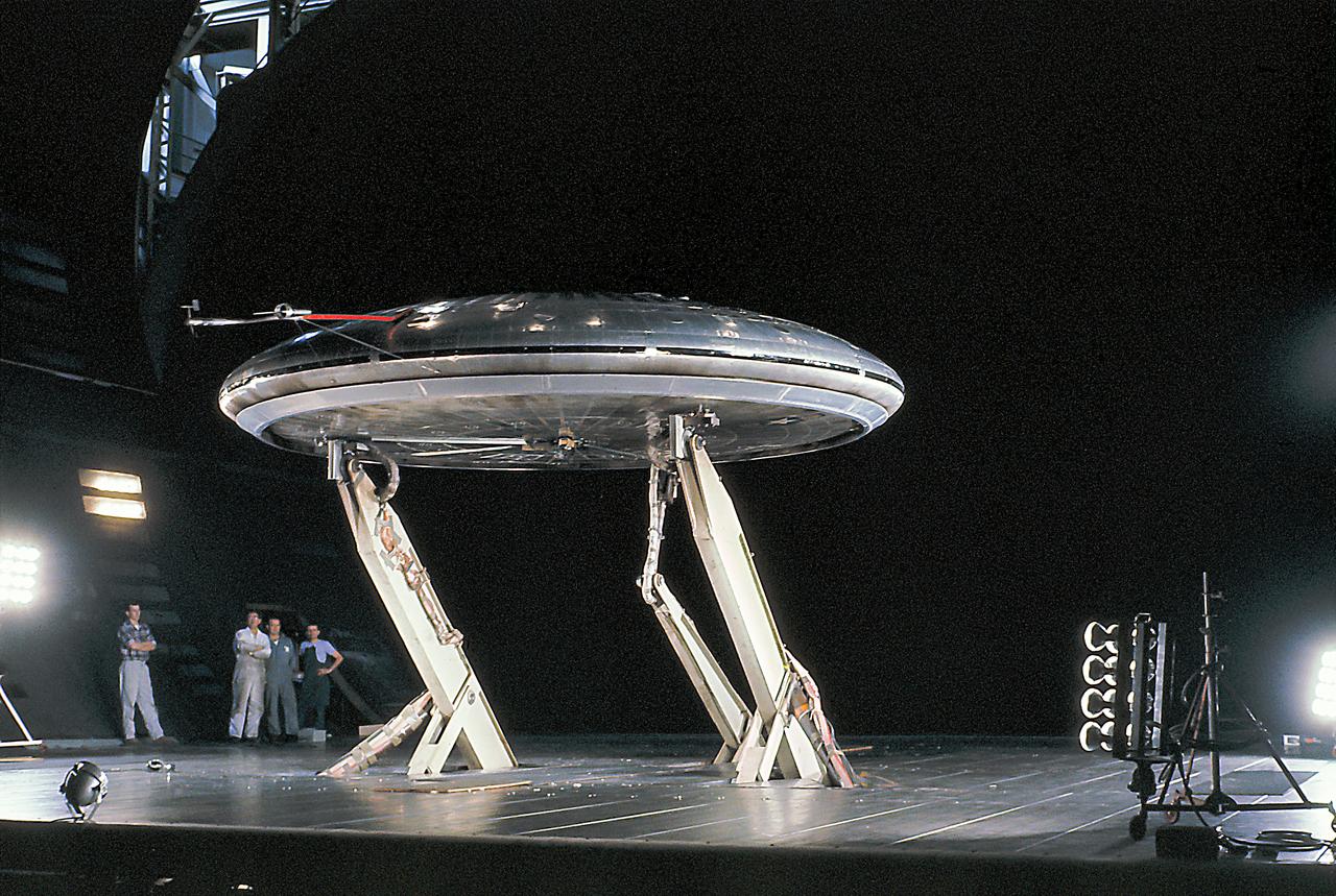
Front 3/4 view of the Avrocar mounted on variable height struts in the Ames 40x80 foot wind tunnel, without tail.
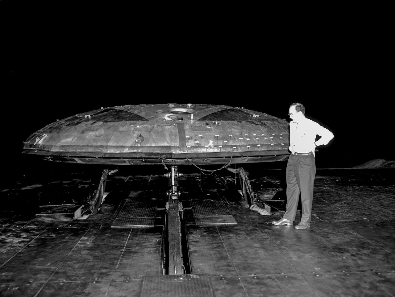
Avrocar with ground board and variable height struts and no tail. Can see focusing ring that controlled the peripheral jet.
Tandem dual ducted fan mounted on ground plane on varriable height struts, 3/4 front view
Front view of the Avrocar on variable height struts in 40x 80 wind tunnel with overhead doors open.
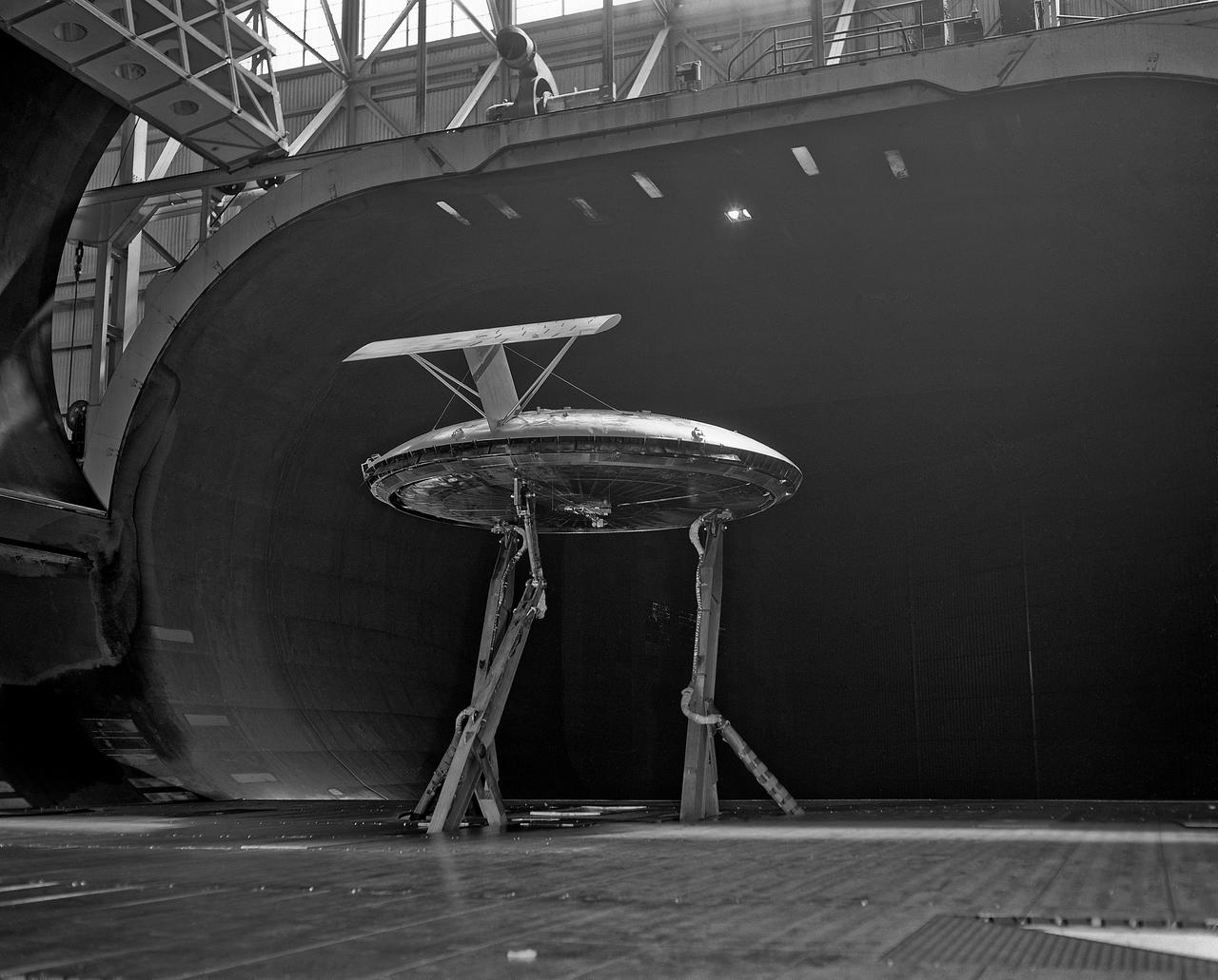
Rear view of the Avrocar with tail, mounted on variable height struts. Overhead doors of the wind tunnel test section open.
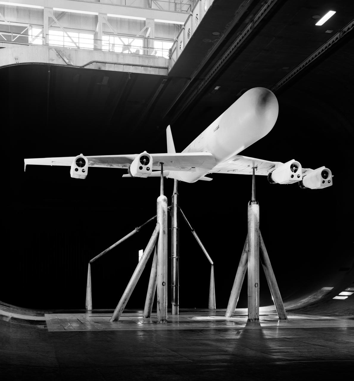
Effects of thrust reversers on the aerodynamics characteristics of a four-engine jet transport model. 1/4 front view on normal struts with thrust reversers.
Top rear view of the avrocar with tail. Tufts (pieces of yarn) attached to top of horizontal tail. Avrocar mounted on variable height struts.
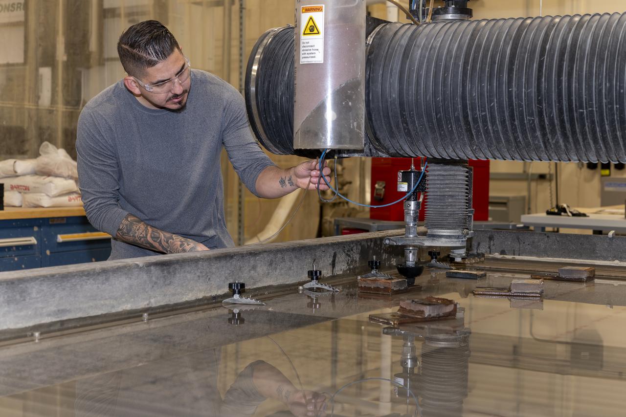
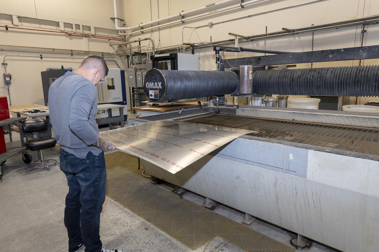
Matthew Sanchez uses a water jet to cut aluminum for the outer layer of the strut for the 10-foot model of the Transonic Truss-Braced Wing at NASA’s Armstrong Flight Research Center, in Edwards, California. The aircraft concept involves a wing braced on an aircraft using diagonal struts that also add lift and could result in significantly improved aerodynamics.
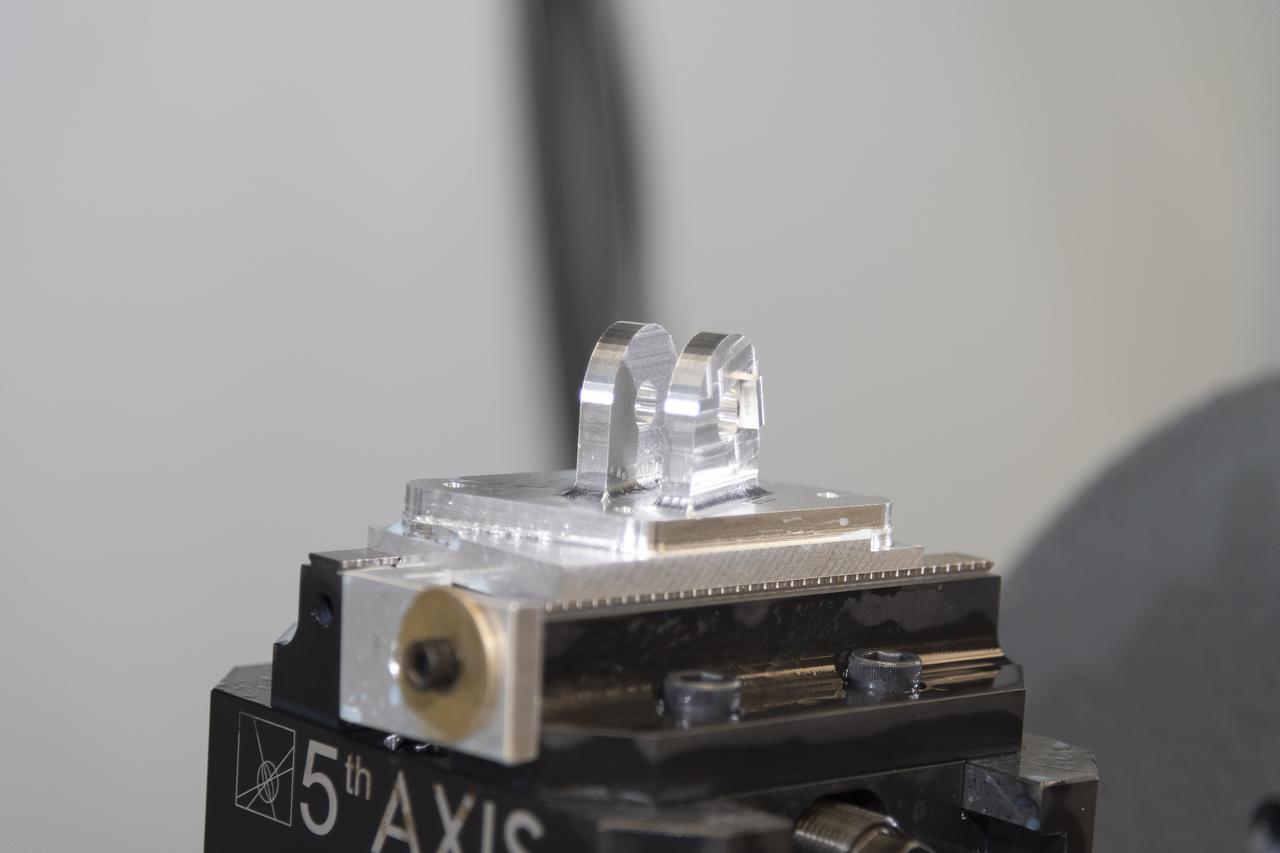
A block of aluminum is transformed by a machine programmed to cut, rotate, and turn it to make a forward wing strut fastener for a 10-foot model of the Transonic Truss-Braced Wing at NASA’s Armstrong Flight Research Center, in Edwards, California. The aircraft concept involves a wing braced on an aircraft using diagonal struts that also add lift and could result in significantly improved aerodynamics.

Jose Vasquez programed a machine to cut, rotate and turn a block of steel to form a jury strut adaptor for a 10-foot model of the Transonic Truss-Braced Wing at NASA’s Armstrong Flight Research Center, in Edwards, California. The aircraft concept involves a wing braced on an aircraft using diagonal struts that also add lift and could result in significantly improved aerodynamics.
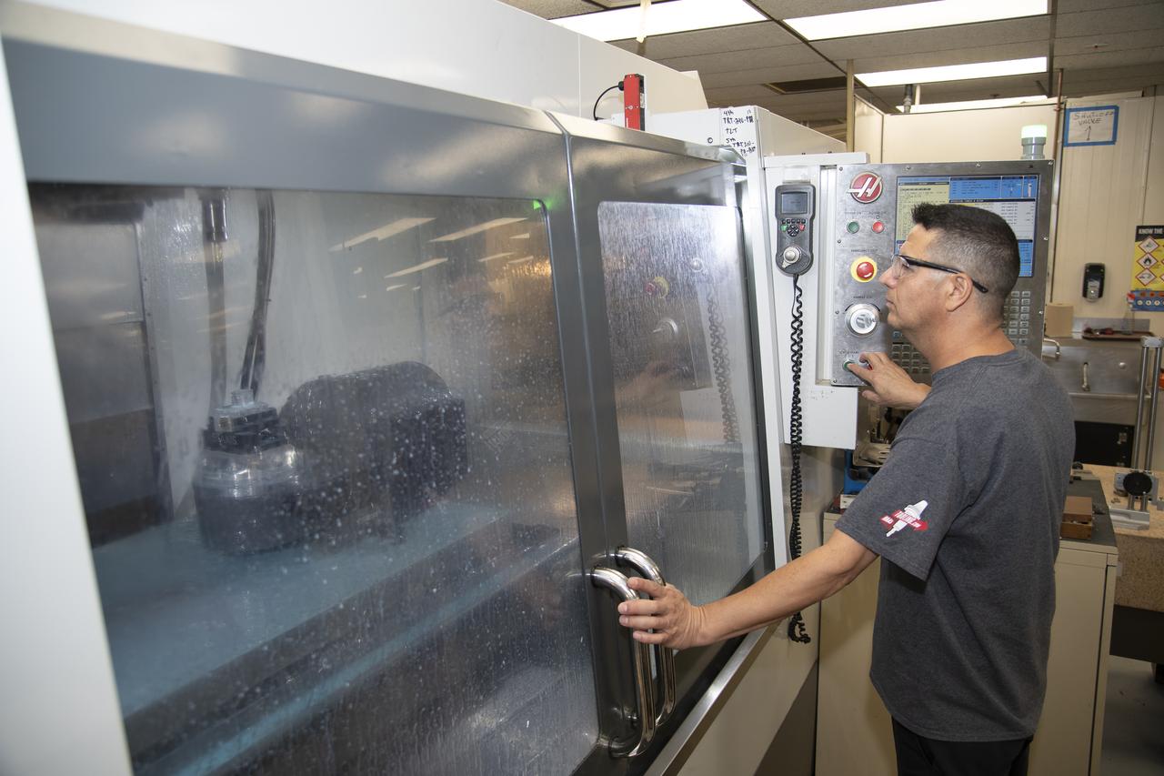
Jose Vasquez uses a machine to cut, rotate and turn a block of aluminum to make a forward wing strut fastener for a 10-foot model of the Transonic Truss-Braced Wing at NASA’s Armstrong Flight Research Center, in Edwards, California. The aircraft concept involves a wing braced on an aircraft using diagonal struts that also add lift and could result in significantly improved aerodynamics.
Matthew Sanchez places the strut and the wing side-by-side before assembling them for a check to ensure they fit together as intended for a 10-foot model of the Transonic Truss-Braced Wing at NASA’s Armstrong Flight Research Center, in Edwards, California. The aircraft concept involves a wing braced on an aircraft using diagonal struts that also add lift and could result in significantly improved aerodynamics.
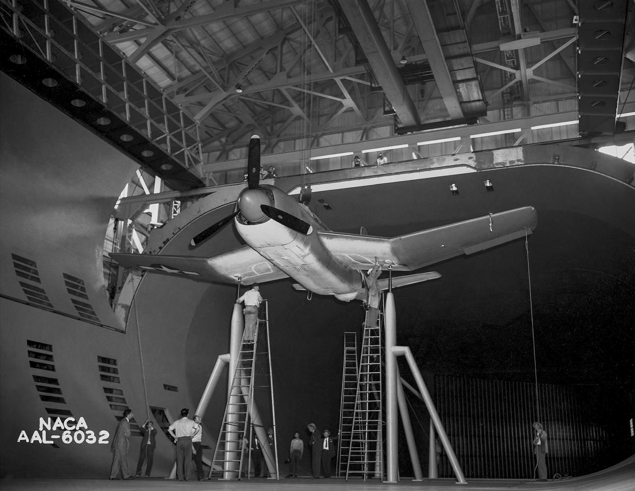
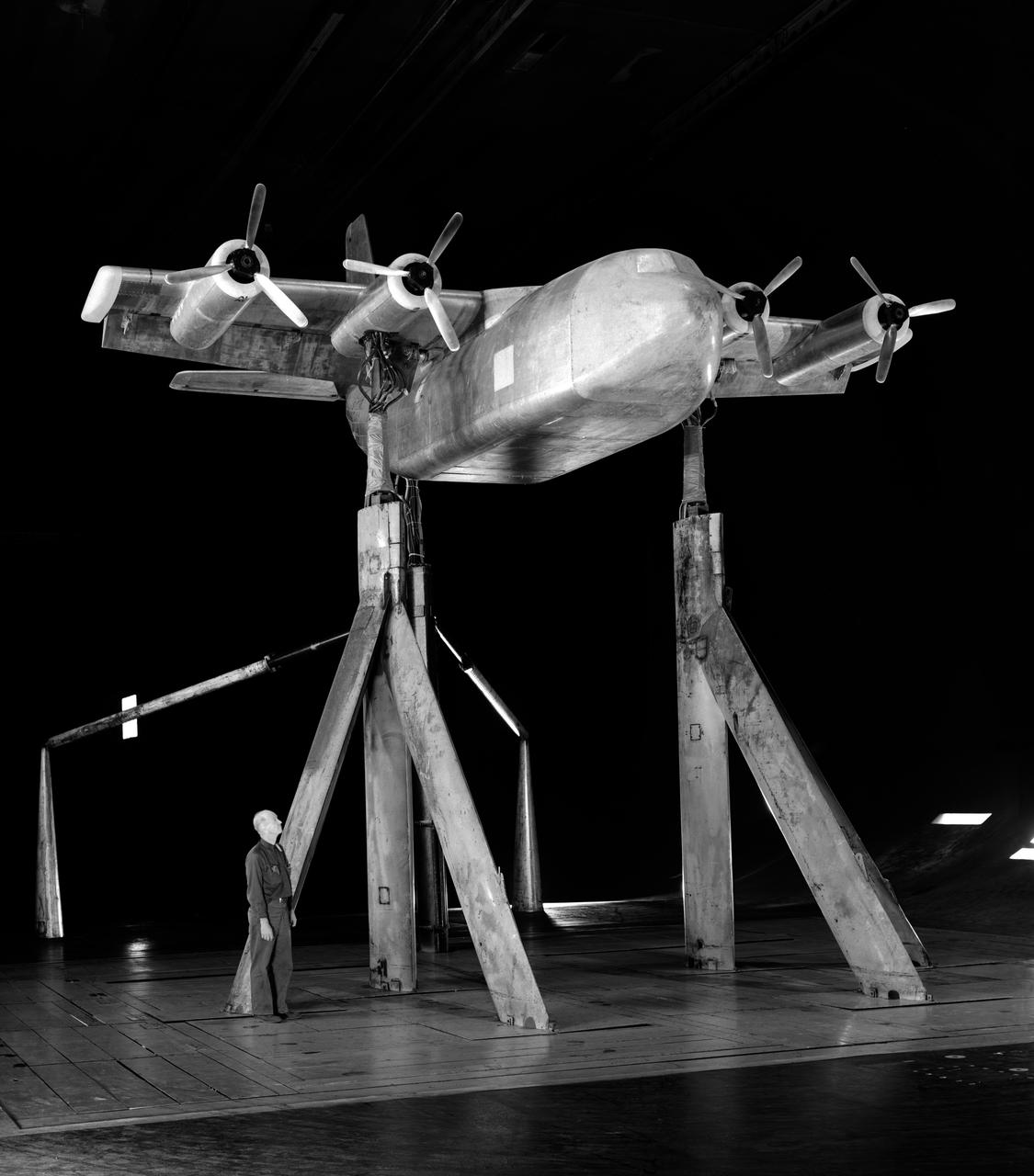
Test section of the Ames 40 x 80 foot wind tunnel with the overhead doors open. XSB2D-1 airplane being lowered onto the struts by the overhead crane. Mechanics and engineers on orchard ladders aligning the model with ball sockets on the struts. The Douglas BTD Destroyer was an American dive/ torpedo bomber developed for the United States Navy during World War II.
A machine cuts, rotates, and turns a block of aluminum to make a forward wing strut fastener for a 10-foot model of the Transonic Truss-Braced Wing at NASA’s Armstrong Flight Research Center, in Edwards, California. The aircraft concept involves a wing braced on an aircraft using diagonal struts that also add lift and could result in significantly improved aerodynamics.
KENNEDY SPACE CENTER, FLA. - A crack formed on a piece of insulation on a strut that attaches the liquid oxygen feedline to External Tank-119, being used to launch space shuttle mission STS-121. This piece of foam, weighing approximately 0.0057 pounds, is three inches long and one-eighth to one-quarter inch wide. It fell from the tank and was recovered by the Ice Team from the mobile launch platform at Pad 39B. It is believed that the rain experienced during yesterday’s launch attempt of Discovery caused water to run down the feedline and form ice near the strut next to the feedline bracket. As the tank warmed and expanded, the ice that formed most likely pinched the foam on the top of the strut, causing a crack and eventual loss of the small piece of foam. Photo credit: NASA
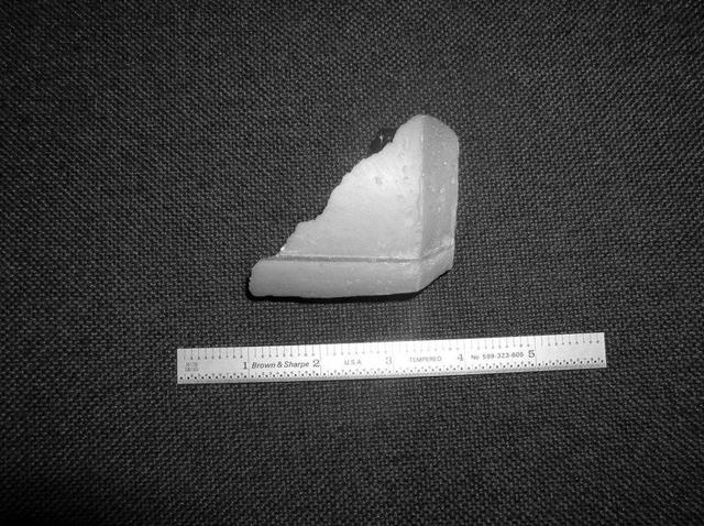
KENNEDY SPACE CENTER, FLA. - A piece of insulation - three inches long, one-eighth to one-quarter inch wide and weighing approximately 0.0057 pounds - was liberated from a strut that attaches the liquid oxygen feedline to External Tank-119. The tank is being used to launch space shuttle mission STS-121. It was recovered by the Ice Team from the mobile launch platform at Pad 39B. It is believed that the rain experienced during yesterday’s launch attempt of Discovery caused water to run down the feedline and form ice near the strut next to the feedline bracket. As the tank warmed and expanded, the ice that formed most likely pinched the foam on the top of the strut, causing a crack and eventual loss of the small piece of foam. Photo credit: NASA
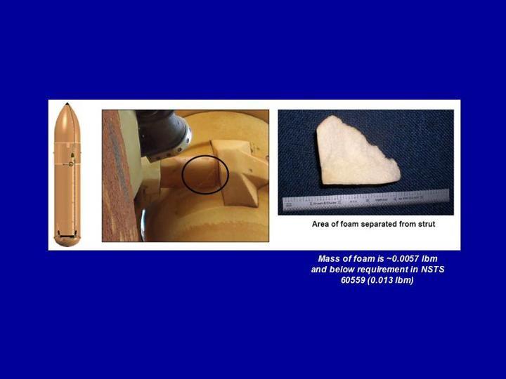
KENNEDY SPACE CENTER, FLA. - A composite image illustrates the size and location of a piece of insulation that was liberated from a strut that attaches the liquid oxygen feedline to External Tank-119. The tank is being used to launch space shuttle mission STS-121. This piece of foam, weighing approximately 0.0057 pounds, is three inches long and one-eighth to one-quarter inch wide and was recovered by the Ice Team from the mobile launch platform at Pad 39B. It is believed that the rain experienced during yesterday’s launch attempt of Discovery caused water to run down the feedline and form ice near the strut next to the feedline bracket. As the tank warmed and expanded, the ice that formed most likely pinched the foam on the top of the strut, causing a crack and eventual loss of the small piece of foam. Photo credit: NASA
KENNEDY SPACE CENTER, FLA. - A piece of insulation was liberated from a strut that attaches the liquid oxygen feedline to External Tank-119, being used to launch space shuttle mission STS-121. This piece of foam, weighing approximately 0.0057 pounds, is three inches long and one-eighth to one-quarter inch wide and was recovered by the Ice Team from the mobile launch platform at Pad 39B. It is believed that the rain experienced during yesterday’s launch attempt of Discovery caused water to run down the feedline and form ice near the strut next to the feedline bracket. As the tank warmed and expanded, the ice that formed most likely pinched the foam on the top of the strut, causing a crack and eventual loss of the small piece of foam. Photo credit: NASA
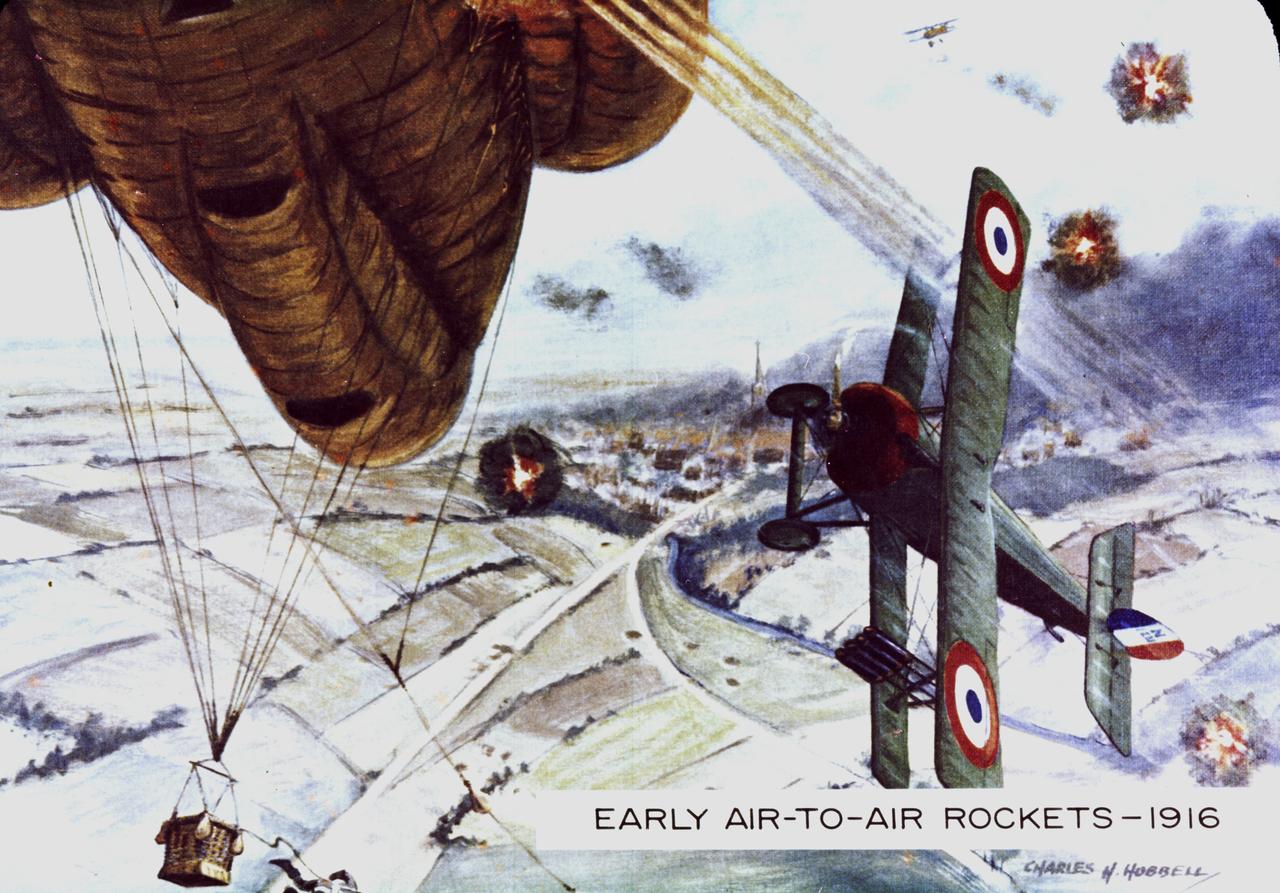
World War I enlisted rockets once again for military purposes. French pilots rigged rockets to the wing struts of their airplanes and aimed them at enemy observation balloons filled with highly inflammable hydrogen.
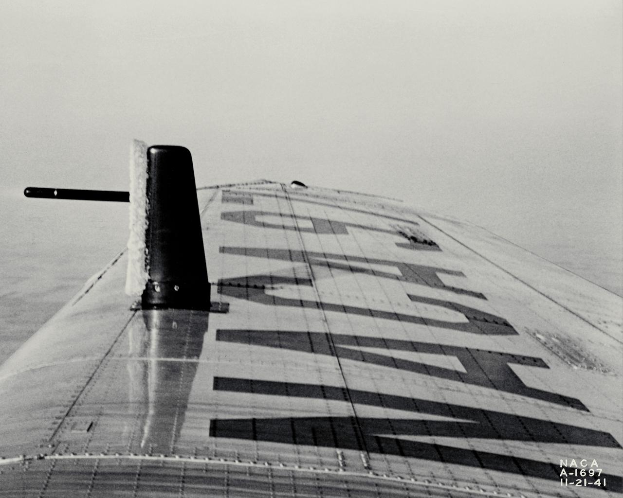
NACA photographer Ice Reearch being conducted at NACA Ames Aeronautical Laboratory on a Lockheed 12-A, NACA 97; test #4, ice on tell-tale strut in flight
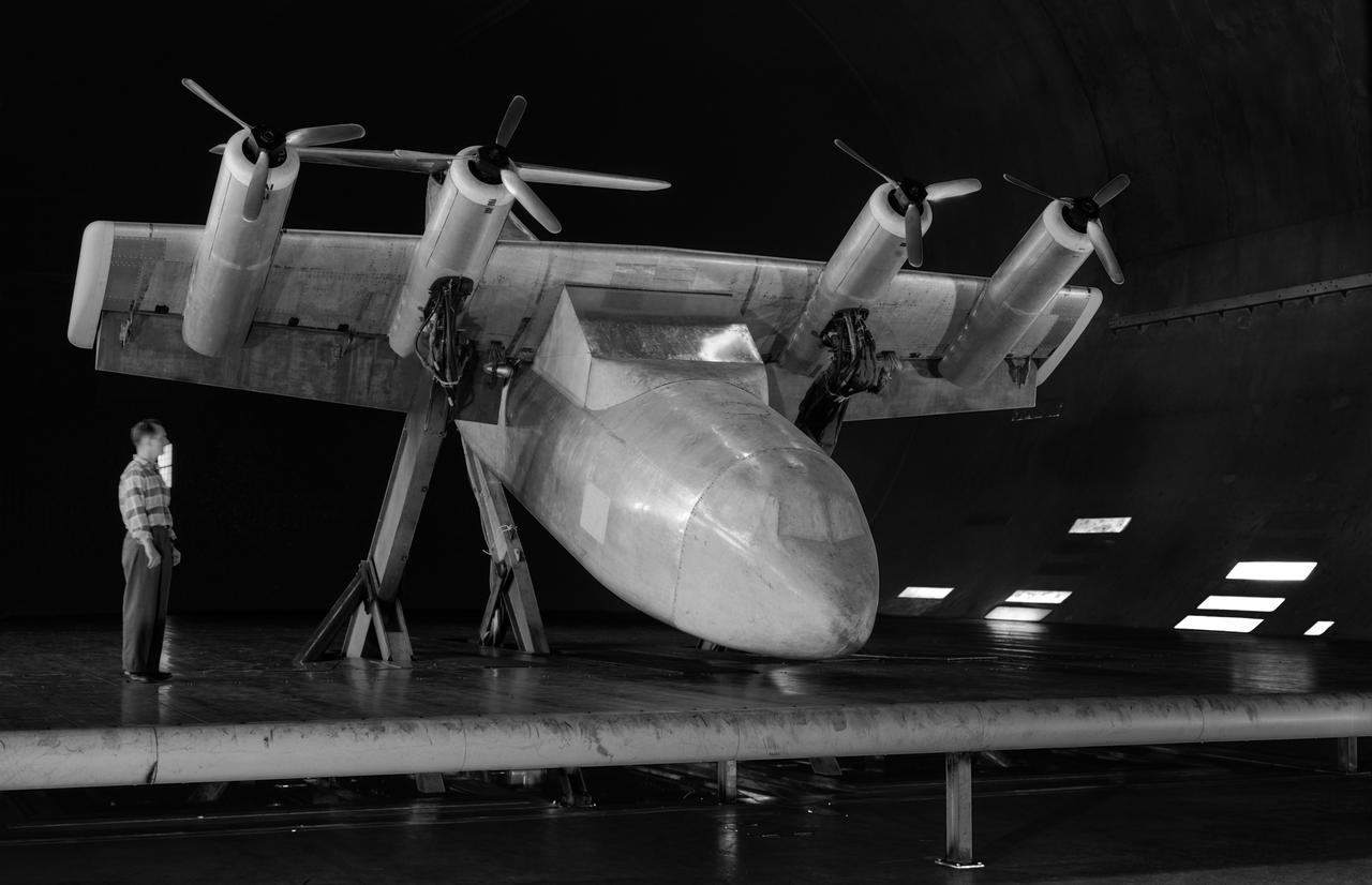
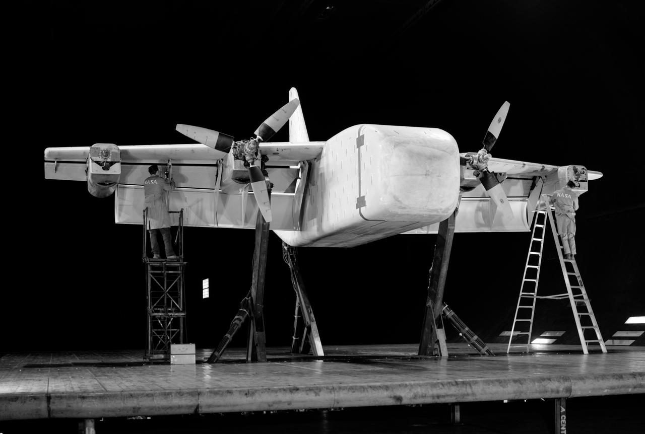
Investigation of a tilt-wing/propeller model with blowing flaps. 3/4 front view, tilt wing model, wing position = 0deg. C-123 fuselage, conventional struts, 4 props
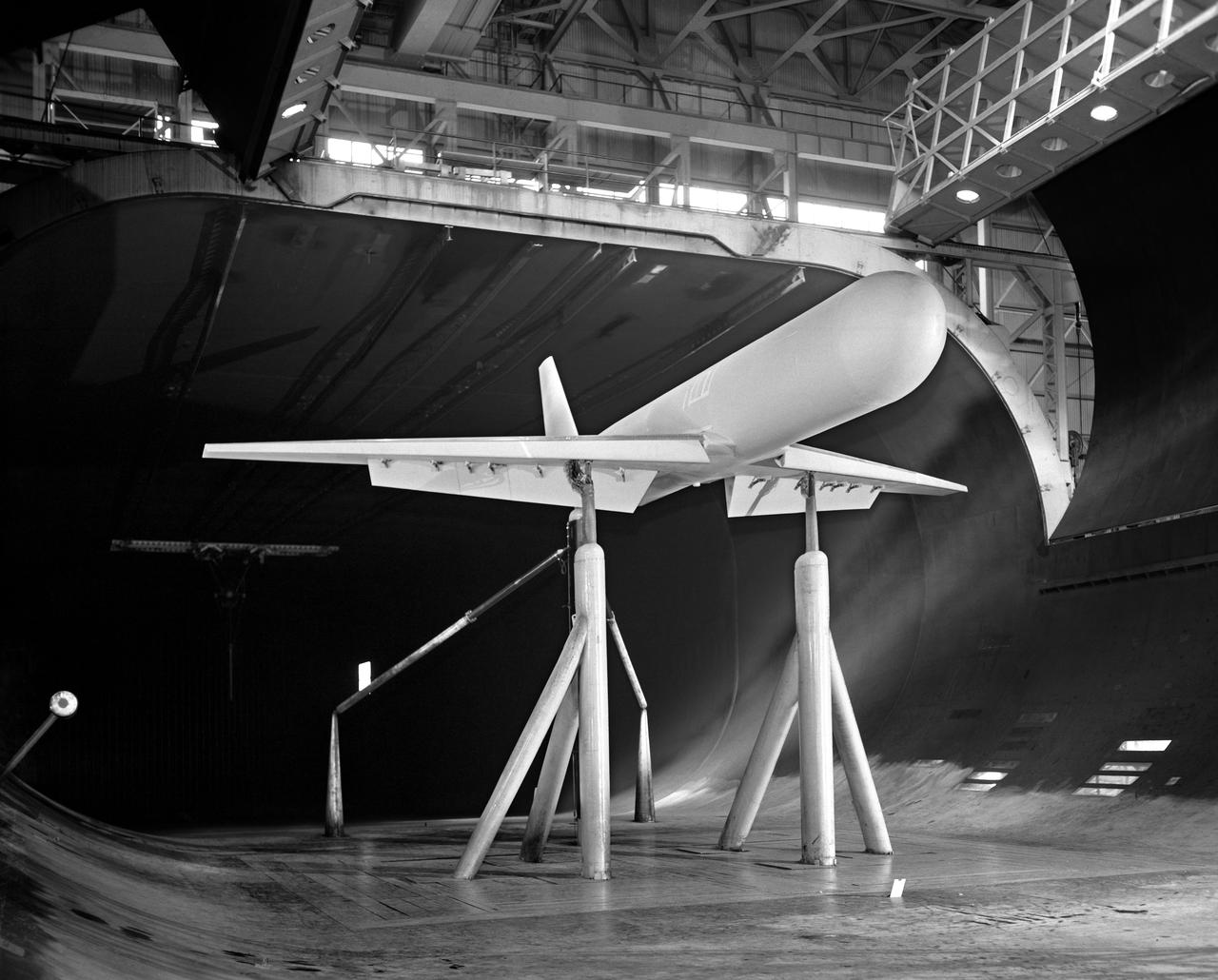
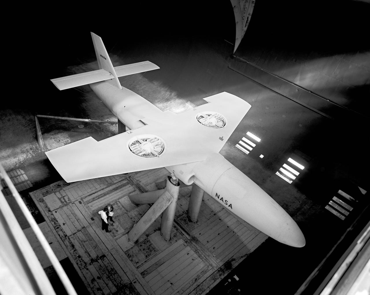
G.E. Fan-in-fuselage model (lifting). 3/4 rear view of fan at low G.P. position. Lift fan on variable height strut for ground effects studies with reaction control. T-Tail.
3/4 front view of model without nacelles on regular struts. Generalized Subsonic Jet Transport model with leading edge and trailing edge blowing BLC in the 40x80 foot wind tunnel at NASA Ames.
G.E. Fan-in-fuselage model (lifting). 3/4 front view of fan at low G.P. position. Lift fan on variable height strut for ground effects studies. T-Tail
Tilt wing propeller model. 3/4 front view. 4 prop tilt wing nose down variable struts on ground board. Leo Holl, NASA Ames Engineer.
Top view if GE fan model, 3/4 top view. Straight wing. 1 fan per wing, conventional struts. Woody Kook, Branch Chief.
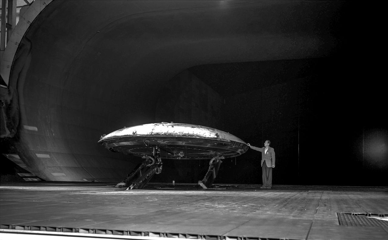
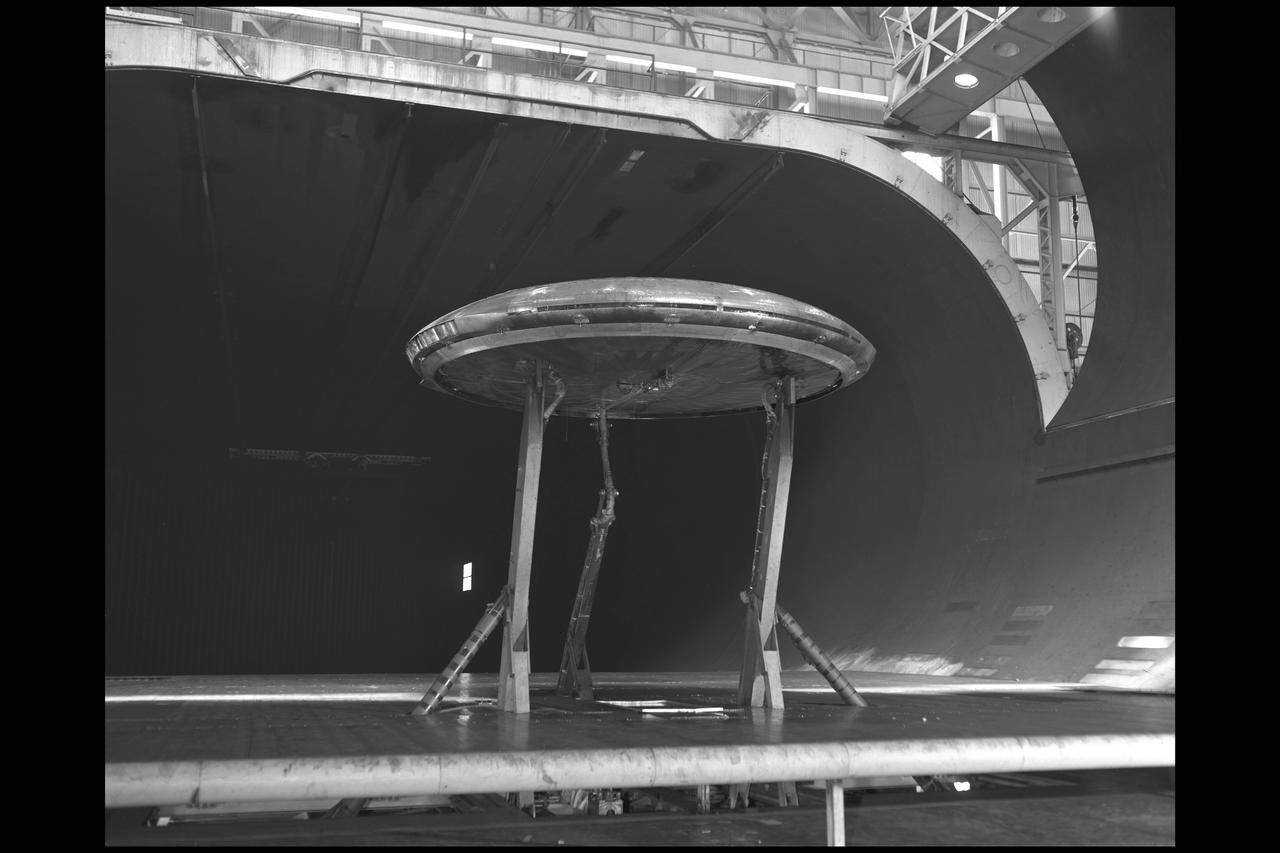
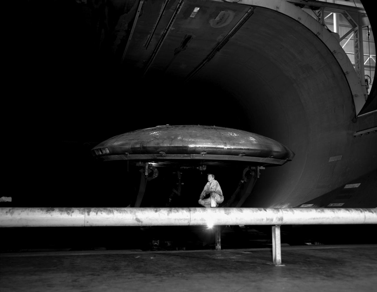
Rear view of the Avrocar without the tail, with ground board and variable height struts. The air force wanted to test the design of a flying saucer with vertical takeoff and landing capability. The design proved unstable without the tail.
XSB2D-1 First test (no number) Aerodynamic test to forecast the take off distance. George Cooper was the A1:H73 pilot. Orchard ladders were used to access the ball socket attachments on the struts.

KENNEDY SPACE CENTER, FLA. -- In bay 3 of the Orbiter Processing Facility, a technician replaces a hydraulic seal in space shuttle Discovery's right main-gear strut. Engineers determined an observed leak of hydraulic fluid in the main landing gear strut exceeded specification and could not be reduced to an acceptable rate. Thus, the leaky seal and three other seals were replaced. Prior to discovery of the leak, the vehicle had been scheduled to roll over Sept. 19 from the OPF to the Vehicle Assembly Building. A new rollover date will be set for Discovery, which is targeted for launch on Oct. 23. Photo credit: NASA/George Shelton
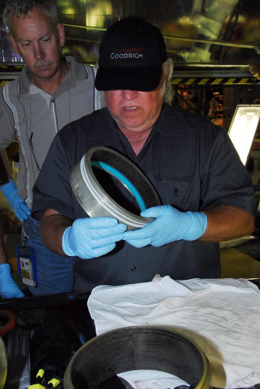
KENNEDY SPACE CENTER, FLA. -- In bay 3 of the Orbiter Processing Facility, B.F. Goodrich technician David Cobb checks the hydraulic seal he replaced in space shuttle Discovery's right main-gear strut. Engineers determined an observed leak of hydraulic fluid in the main landing gear strut exceeded specification and could not be reduced to an acceptable rate. Thus, the leaky seal and three other seals were replaced. Prior to discovery of the leak, the vehicle had been scheduled to roll over Sept. 19 from the OPF to the Vehicle Assembly Building. A new rollover date will be set for Discovery, which is targeted for launch on Oct. 23. Photo credit: NASA/George Shelton

Aaron Rumsey and Beto Hinojos carefully add weight to a 6-foot model of the Transonic Truss-Braced Wing at NASA’s Armstrong Flight Research Center, in Edwards, California. The aircraft concept involves a wing braced on an aircraft using diagonal struts that also add lift and could result in significantly improved aerodynamics.
Researchers test a 10-foot Mock Truss-Braced Wing at NASA’s Armstrong Flight Research Center in Edwards, California. Frank Pena, test director, checks the mock wing. The aircraft concept involves a wing braced on an aircraft using diagonal struts that also add lift and could result in significantly improved aerodynamics.
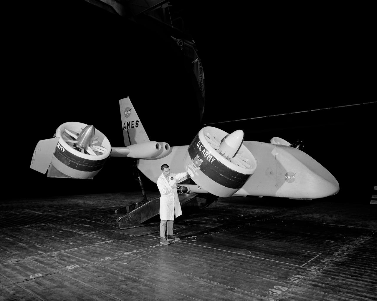
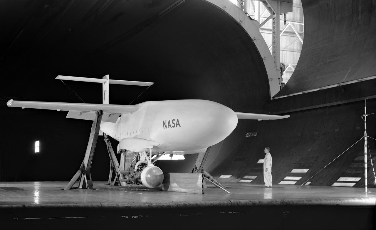
3/4 front view VZ-11 ground test - variable height struts. Engines of the VZ-11 are a pair of General Electric J85-5 turbojets, mounted in high in the centre fuselage, well away from fan disturbance. Designed in the Ames 40x80 foot wind tunnel.
Researchers test a 10-foot Mock Truss-Braced Wing at NASA’s Armstrong Flight Research Center in Edwards, California. The aircraft concept involves a wing braced on an aircraft using diagonal struts that also add lift and could result in significantly improved aerodynamics.
Matthew Sanchez assembles wing ribs for a 10-foot model of the Transonic Truss-Braced Wing at NASA’s Armstrong Flight Research Center, in Edwards, California. The aircraft concept involves a wing braced on an aircraft using diagonal struts that also add lift and could result in significantly improved aerodynamics.
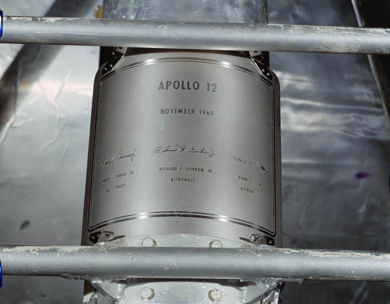
S69-53326 (November 1969) --- Close-up view of a replica of the plaque which the Apollo 12 astronauts will leave on the moon in commemoration of their flight. The plaque will be attached to the ladder on the landing gear strut on the descent stage of the Apollo 12 Lunar Module (LM). Apollo 12 will be the United States' second lunar landing mission.
Matthew Sanchez assembles wing ribs to the 10-foot model of the Transonic Truss-Braced Wing at NASA’s Armstrong Flight Research Center, in Edwards, California. The aircraft concept involves a wing braced on an aircraft using diagonal struts that also add lift and could result in significantly improved aerodynamics.
Collins Aerodyne vertical take-off and landing (VTOL) aircraft investigations. Ground plane support system. 3/4 front view. Dave Koening (from Collins Aerodyne) in photo. Mounted on variable height struts, ground board system, zero degree angle of attack. 01/11/1960
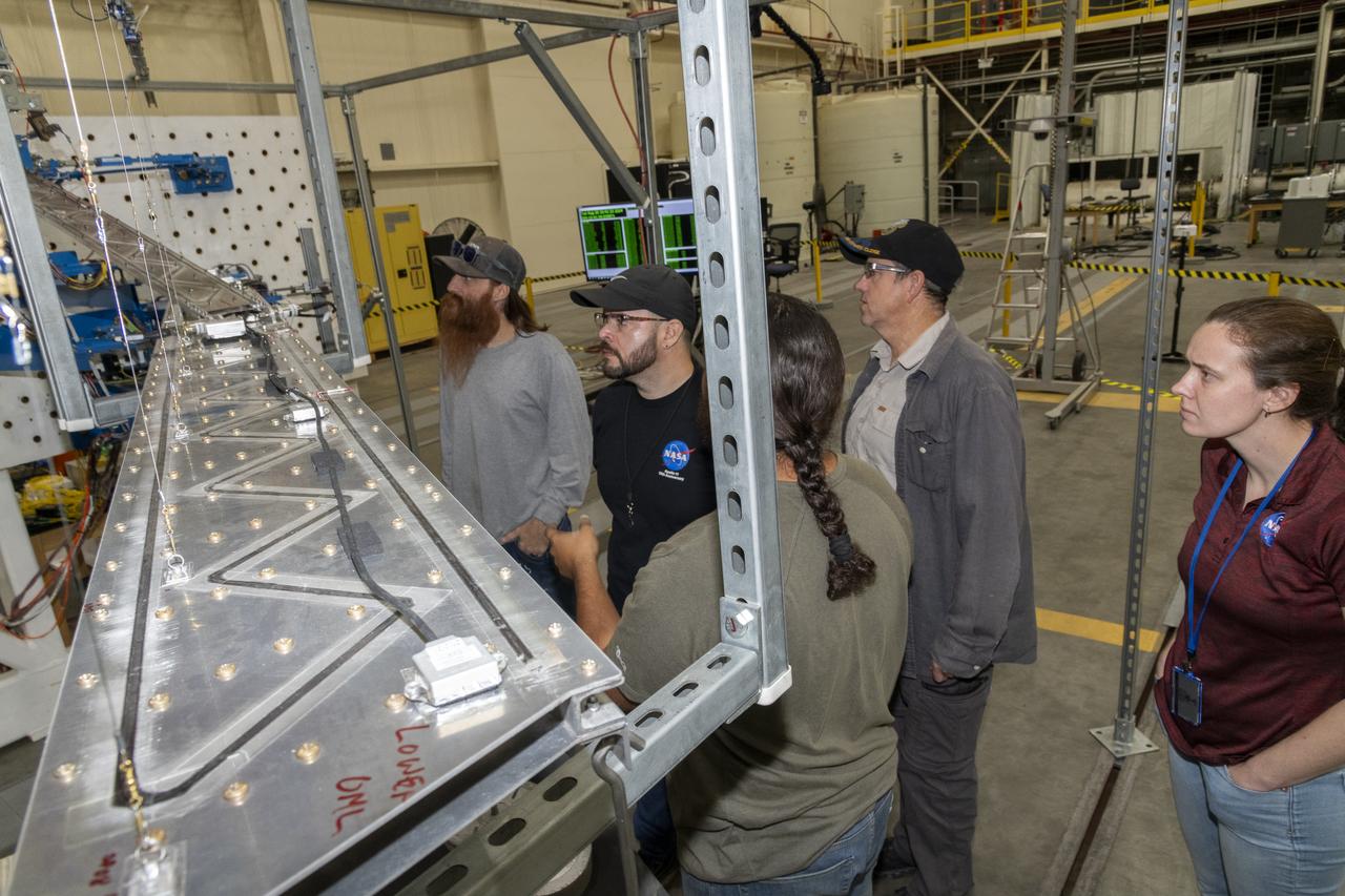
Researchers test a 10-foot Mock Truss-Braced Wing at NASA’s Armstrong Flight Research Center in Edwards, California. The test team makes observations between tests. The aircraft concept involves a wing braced on an aircraft using diagonal struts that also add lift and could result in significantly improved aerodynamics.
Matthew Sanchez, left, consults with Sal Navarro on assembling wing ribs to the 10-foot model of the Transonic Truss-Braced Wing at NASA’s Armstrong Flight Research Center, in Edwards, California. The aircraft concept involves a wing braced on an aircraft using diagonal struts that also add lift and could result in significantly improved aerodynamics.
3/4 front view of Avrocar without tail, showing ground board and variable height struts. The ground board minimizes the boundary layer on the floor under the model. black and white negative: KODAK T-MAX 100 Professional. SBA settings neutral SBA on, color SBA on
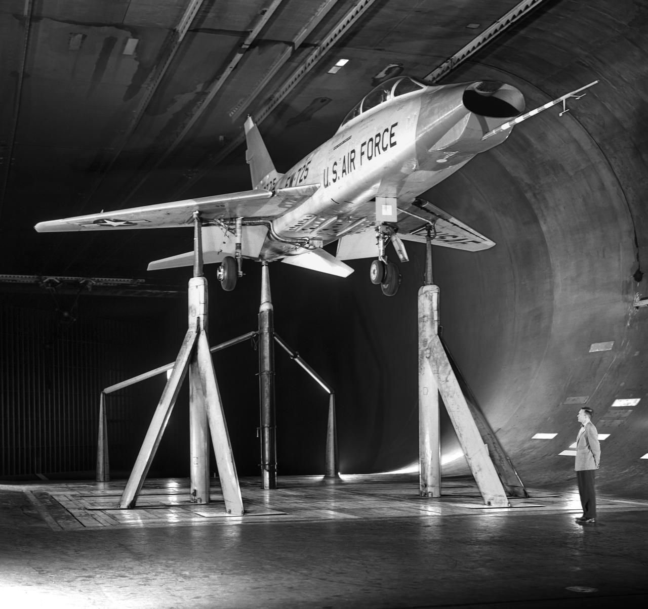
North American F-100-F airplane, equipped with thrust reversers, full scale wind tunnel test. 3/4 front view of F-100-F airplane with North American Aviation thrust reverser. On standard 40x80 struts landing gear down. Mark Kelly, branch chief in photo.
3/4 front right side only with Tim Wills on right and Charles Greco, mechanic. Large flaps on Variable height struts. XC-142 was a tri-service tiltwing experimental aircraft designed to investigate the operational suitability of vertical/short takeoff and landing (V/STOL) transports.
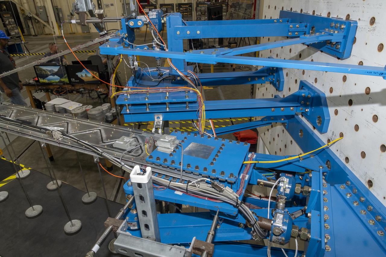
Researchers test a 10-foot Mock Truss-Braced Wing at NASA’s Armstrong Flight Research Center in Edwards, California. The infrastructure, in blue, holds the wing and truss and enables the test. The aircraft concept involves a wing braced on an aircraft using diagonal struts that also add lift and could result in significantly improved aerodynamics.
KENNEDY SPACE CENTER, FLA. --In bay 3 of the Orbiter Processing Facility, United Space Alliance technicians reassemble space shuttle Discovery's right main-gear strut back together. The components were removed in order to replace a hydraulic seal inside. Engineers determined an observed leak of hydraulic fluid in the main landing gear strut exceeded specification and could not be reduced to an acceptable rate. Thus, the leaky seal and three other seals were replaced. Prior to discovery of the leak, the vehicle had been scheduled to roll over Sept. 19 from the OPF to the Vehicle Assembly Building. A new rollover date will be set for Discovery, which is targeted for launch on Oct. 23. Photo credit: NASA/George Shelton
KENNEDY SPACE CENTER, FLA. -- In bay 3 of the Orbiter Processing Facility, United Space Alliance technicians make final adjustments on space shuttle Discovery's starboard landing gear. The components were removed in order to replace a hydraulic seal in the right main-gear strut. Engineers determined an observed leak of hydraulic fluid in the main landing gear strut exceeded specification and could not be reduced to an acceptable rate. Thus, the leaky seal and three other seals were replaced. Prior to discovery of the leak, the vehicle had been scheduled to roll over Sept. 19 from the OPF to the Vehicle Assembly Building. A new rollover date will be set for Discovery, which is targeted for launch on Oct. 23. Photo credit: NASA/George Shelton

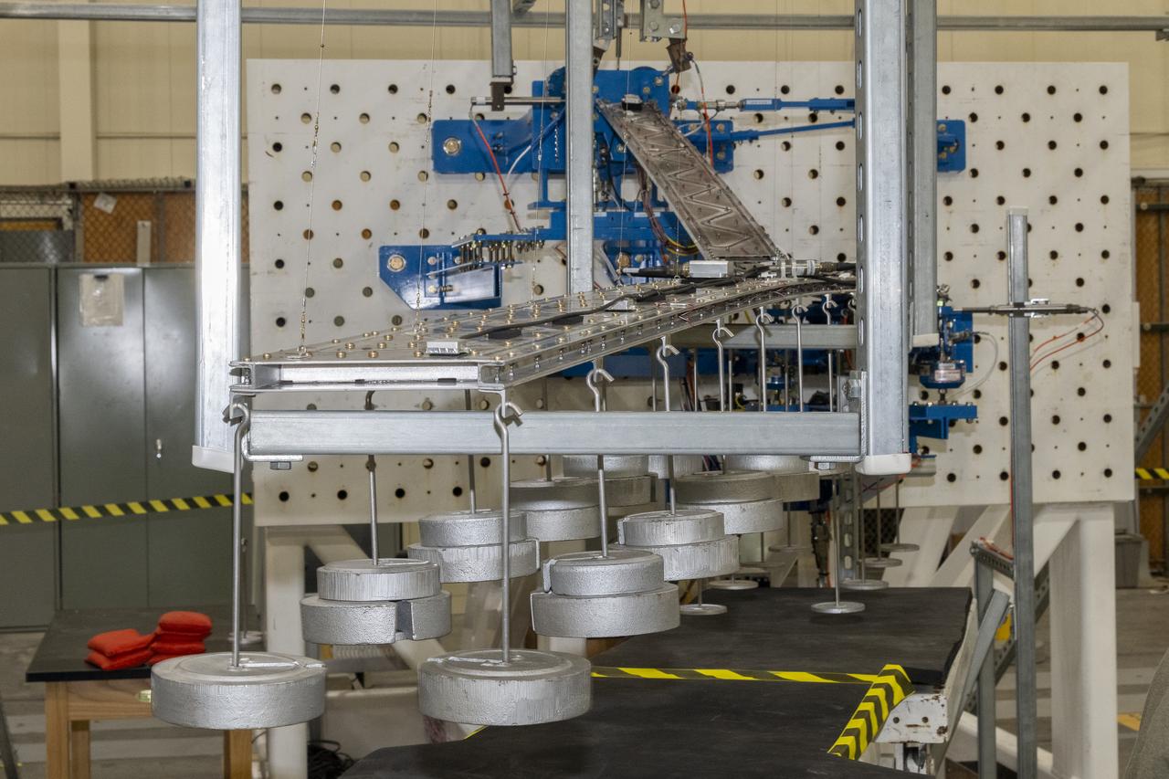
Researchers test a 10-foot Mock Truss-Braced Wing at NASA’s Armstrong Flight Research Center in Edwards, California. From left, test director Frank Pena and Ray Sadler watch as Lucas Oramas, left, and Charlie Eloff add weight to the test wing to apply stress used to determine its limits. The aircraft concept involves a wing braced on an aircraft using diagonal struts that also add lift and could result in significantly improved aerodynamics.

Researchers test a 10-foot Mock Truss-Braced Wing at NASA’s Armstrong Flight Research Center in Edwards, California. Jonathan Lopez, from left, and Jeff Howell watch test data as it is collected. The aircraft concept involves a wing braced on an aircraft using diagonal struts that also add lift and could result in significantly improved aerodynamics.
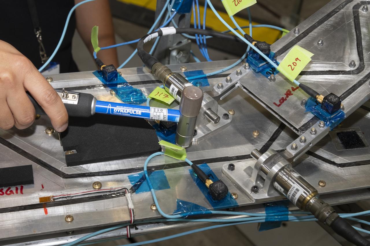
Researchers test a 10-foot Mock Truss-Braced Wing at NASA’s Armstrong Flight Research Center in Edwards, California. Ben Park, NASA mock wing ground vibration test director, taps the wing structure with an instrumented hammer in key locations and sensors monitor the results. The aircraft concept involves a wing braced on an aircraft using diagonal struts that also add lift and could result in significantly improved aerodynamics.
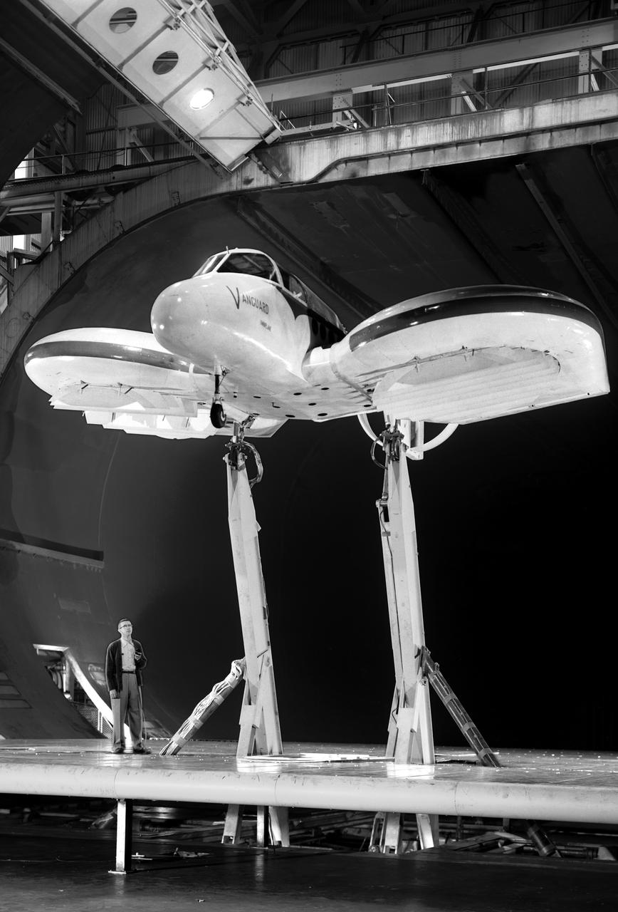
Vanguard 2C vertical take-off and landing (VTOL) airplane, wind tunnel test. Front view from below, model 14 1/2 feet high disk off. Nasa Ames engineer Ralph Maki in photo. Variable height struts and ground plane, low pressure ratio, fan in wing. 02/01/1960.
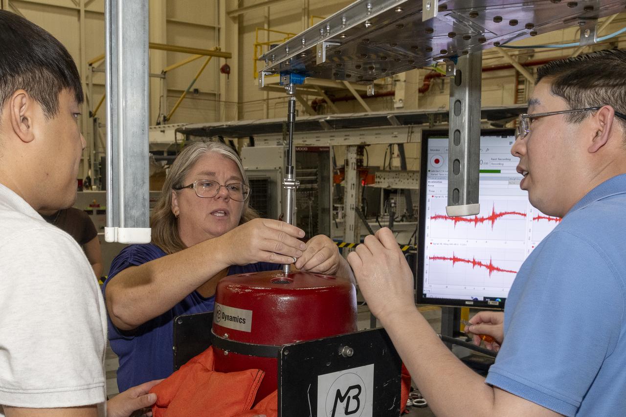
Researchers test a 10-foot Mock Truss-Braced Wing at NASA’s Armstrong Flight Research Center in Edwards, California. From left, ground vibration test director Ben Park, Natalie Spivey, and Samson Truong, prepare for a vibration test. The aircraft concept involves a wing braced on an aircraft using diagonal struts that also add lift and could result in significantly improved aerodynamics.
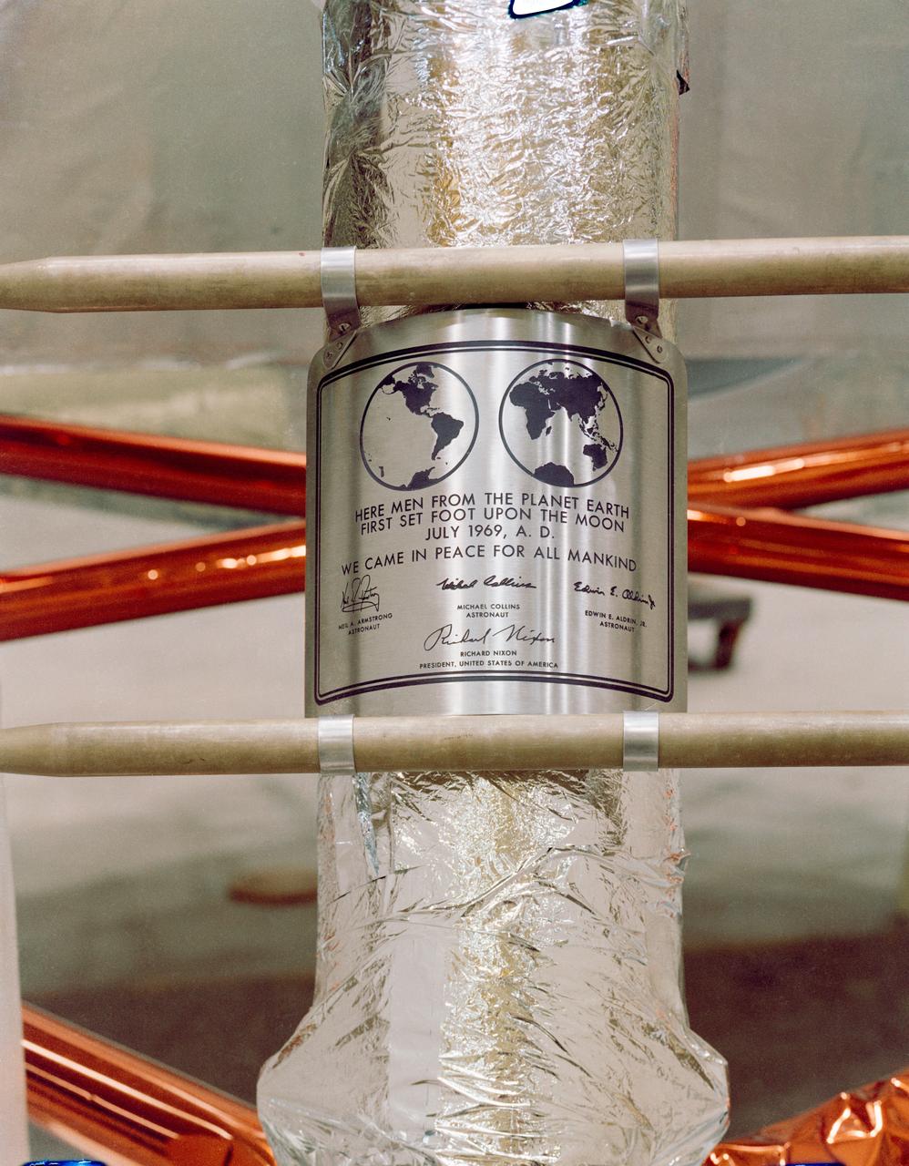
S69-38749 (July 1969) --- Close-up view of the plaque which the Apollo 11 astronauts will leave behind on the moon in commemoration of the historic event. The plaque is made of stainless steel measuring nine by seven and five-eighths inches, and one-sixteenth inch thick. The plaque will be attached to the ladder on the landing gear strut on the descent stage of the Apollo 11 Lunar Module (LM). Covering the plaque during flight will be a thin sheet of stainless steel which will be removed on the lunar surface.
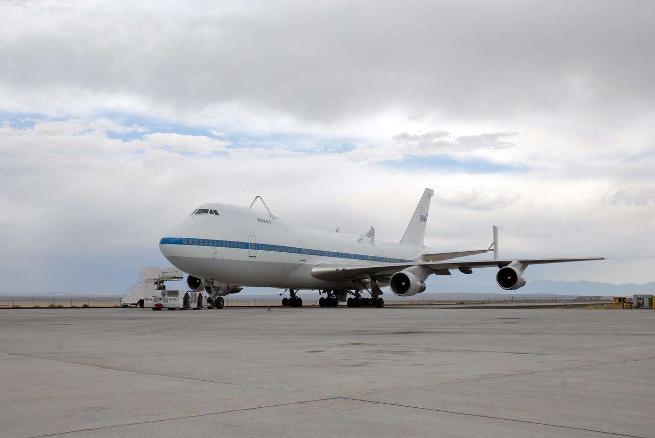
CAPE CANAVERAL, Fla. – This Shuttle Carrier Aircraft, or SCA, a modified Boeing 747, is fitted with struts on top that will attach to space shuttle Atlantis for a piggyback flight. Atlantis landed at Edwards on May 24, which concluded mission STS-125, after two landing opportunities at Kennedy were waved off due to weather concerns. Atlantis is being returned to Florida on a ferry flight on the SCA. Atlantis' next assignment is the STS-129 mission, targeted to launch in November 2009. Photo credit: NASA/Ben Smegelsky
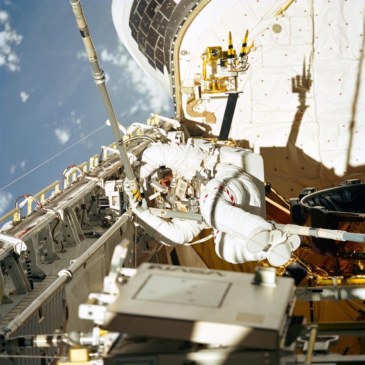
STS049-77-023 (14 May 1992) --- Astronaut Thomas D. Akers joins three struts together, as fourth period of extravehicular activity (EVA) proceeds in the Space Shuttle Endeavour's cargo bay. The purpose of the final EVA on this nine-day mission was the evaluation of Assembly of Station by EVA Methods (ASEM). The scene was recorded on 70mm film by a fellow crew member in the Space Shuttle's cabin. Astronaut Kathryn C. Thornton (out of frame) joined Akers on the 7 1/2 hour EVA.
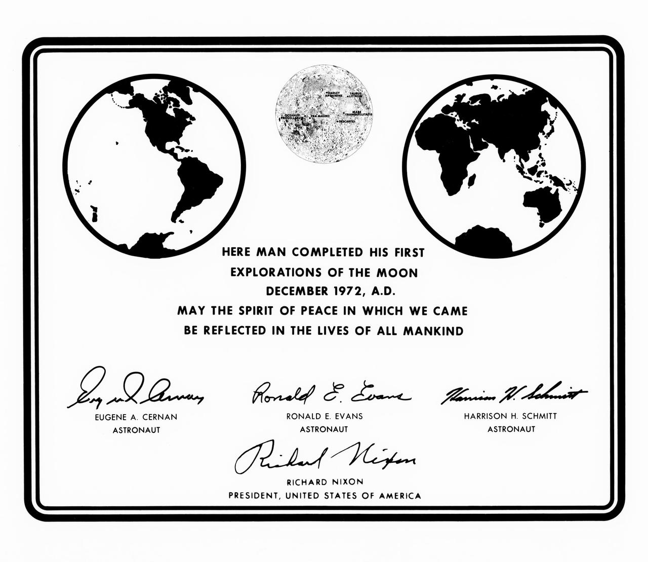
S72-55169 (14 Dec. 1972) --- A photographic replica of the plaque which the Apollo 17 astronauts left behind at the Taurus-Littrow landing site. Apollo 17 is the final lunar landing mission in NASA's Apollo program. The commemorative plaque was unveiled at the close of the third extravehicular activity (EVA). The plaque is made of stainless steel measuring nine by seven and five-eighths inches, and one-sixteenth inch thick. It is attached to the ladder on the landing gear strut on the descent stage of Apollo 17 Lunar Module (LM) "Challenger".
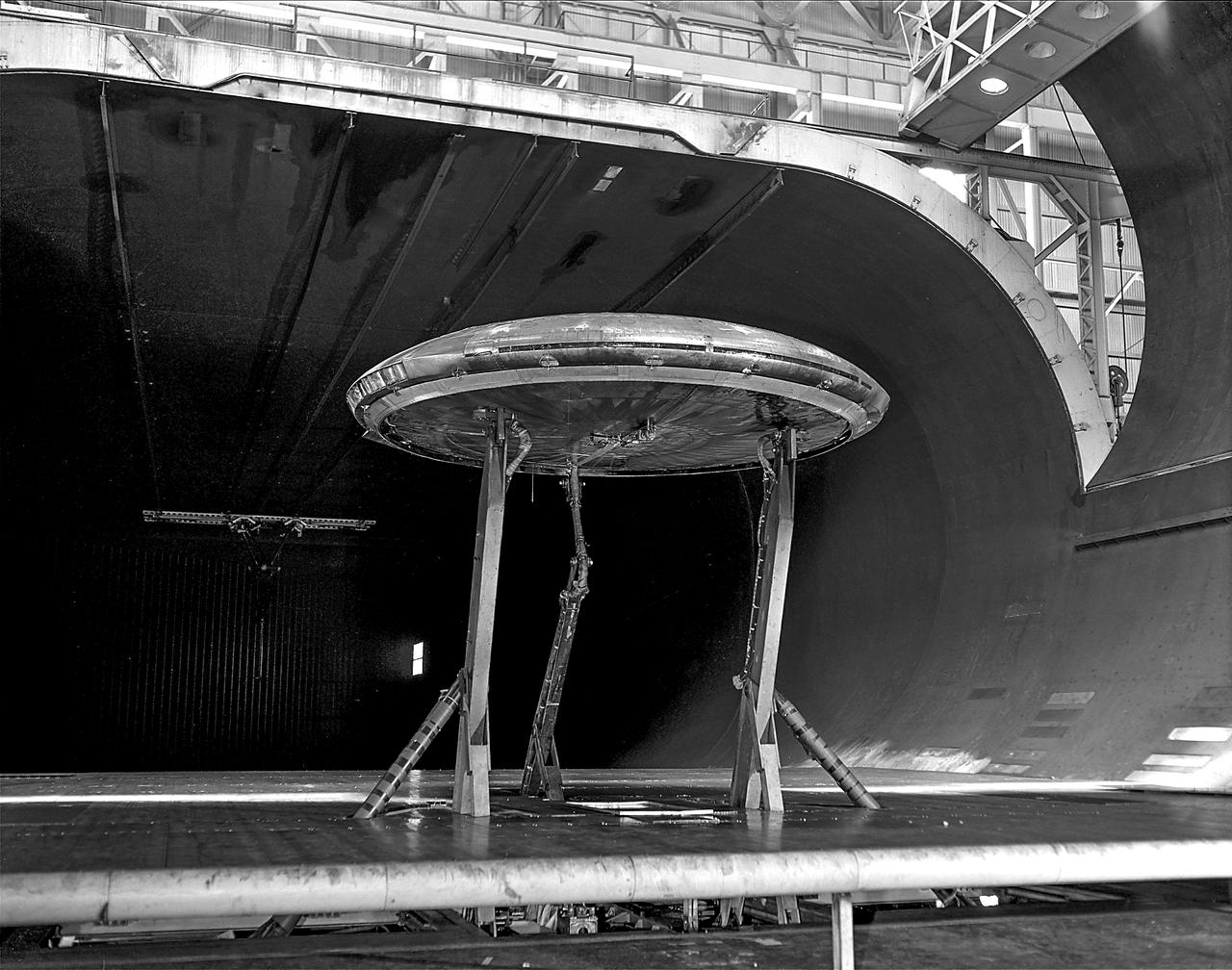
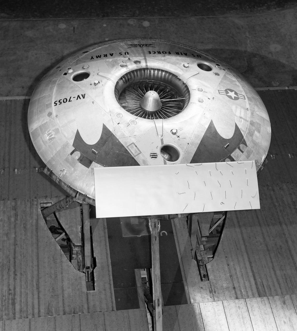
Rear view of the Avrocar with tail, mounted on variable height struts. Overhead doors of the wind tunnel test section open. The first Avrocar, S/N 58-7055 (marked AV-7055), after tethered testing, became the "wind tunnel" test model at NASA Ames, where it remained in storage from 1961 until 1966, when it was donated to the National Air and Space Museum, in Suitland, Maryland.
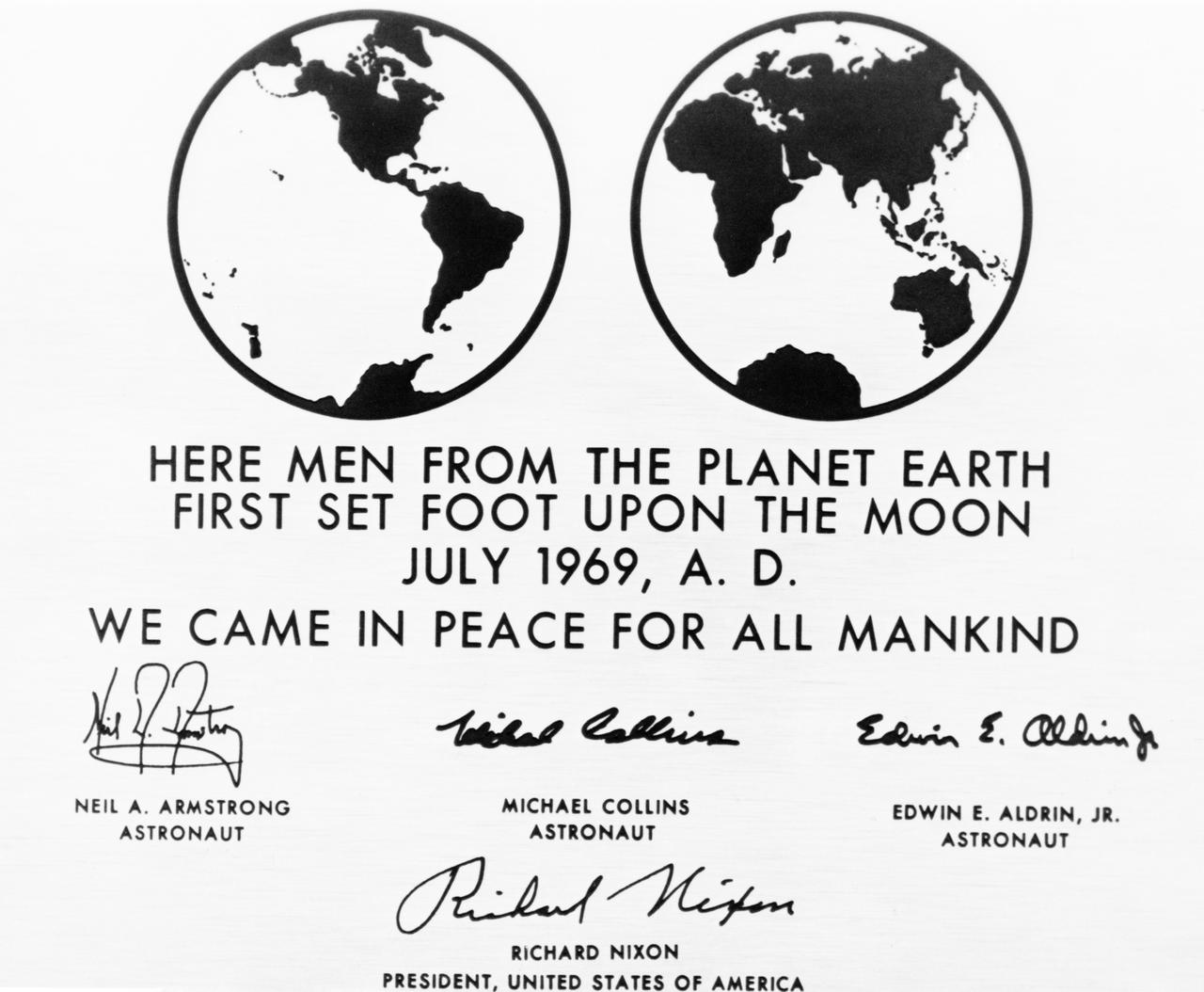
S69-39334 (July 1969) --- This is a replica of the plaque which the Apollo 11 astronauts will leave behind on the moon in commemoration of the historic event. The plaque is made of stainless steel, measuring nine by seven and five-eighths inches, and one-sixteenth inch thick. The plaque will be attached to the ladder on the landing gear strut on the descent stage of the Apollo 11 Lunar Module (LM). Covering the plaque during the flight will be a thin sheet of stainless steel which will be removed on the lunar surface.
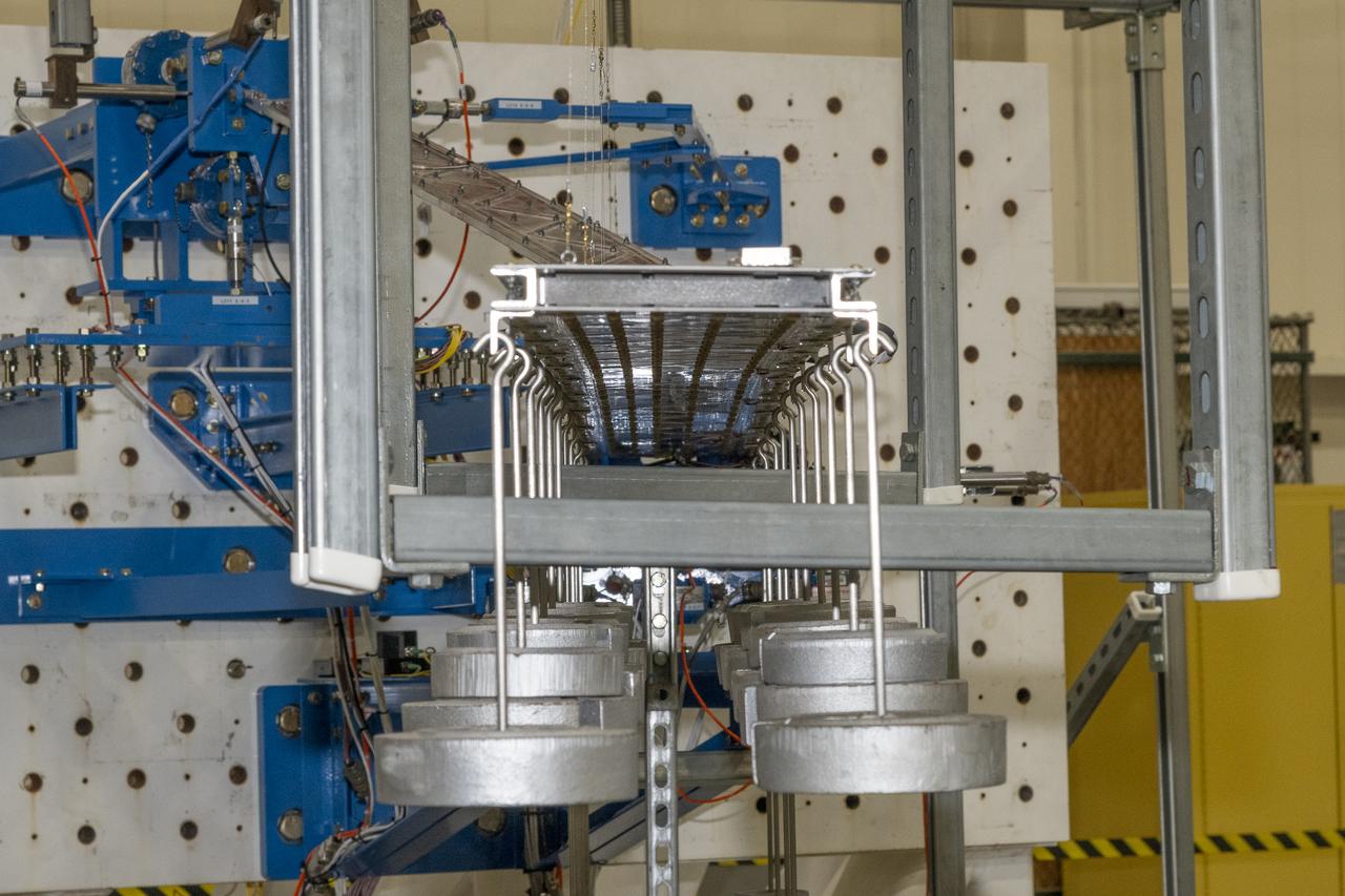
Researchers test a 10-foot Mock Truss-Braced Wing at NASA’s Armstrong Flight Research Center in Edwards, California. Weights are hung from the wing to apply stress used to determine its limits. The aircraft concept involves a wing braced on an aircraft using diagonal struts that also add lift and could result in significantly improved aerodynamics.
Researchers test a 10-foot Mock Truss-Braced Wing at NASA’s Armstrong Flight Research Center in Edwards, California. Weights are added to the wingtip to apply stress used to determine its limits. The aircraft concept involves a wing braced on an aircraft using diagonal struts that also add lift and could result in significantly improved aerodynamics.
Researchers test a 10-foot Mock Truss-Braced Wing at NASA’s Armstrong Flight Research Center in Edwards, California. Charlie Eloff, left, and Lucas Oramas add weight to the test wing to apply stress used to determine its limits. The aircraft concept involves a wing braced on an aircraft using diagonal struts that also add lift and could result in significantly improved aerodynamics.
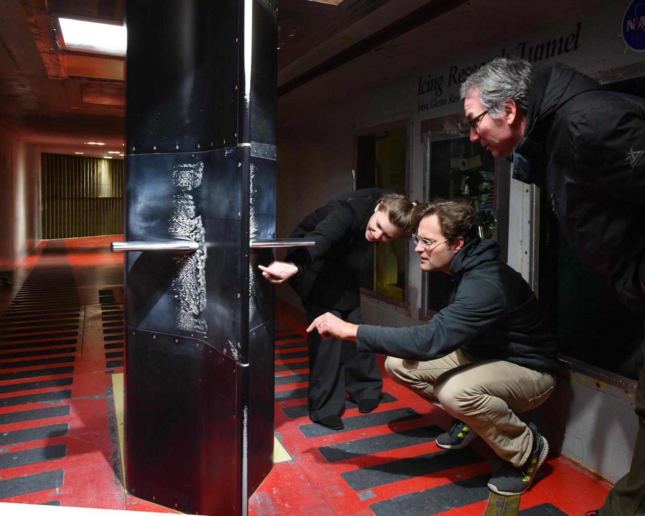
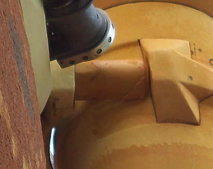
Pictured is a model to study the ice collection on struts in jet engines during flight. Researchers inspect the ice after the model encounters a simulated icing cloud during testing. Super cooled water created from the icing cloud that flows though the wind tunnel. The super cooled water forms ice on contact with the test model. Researchers then inspect the ice formation before laser scanning of the ice formation for further research and analysis.
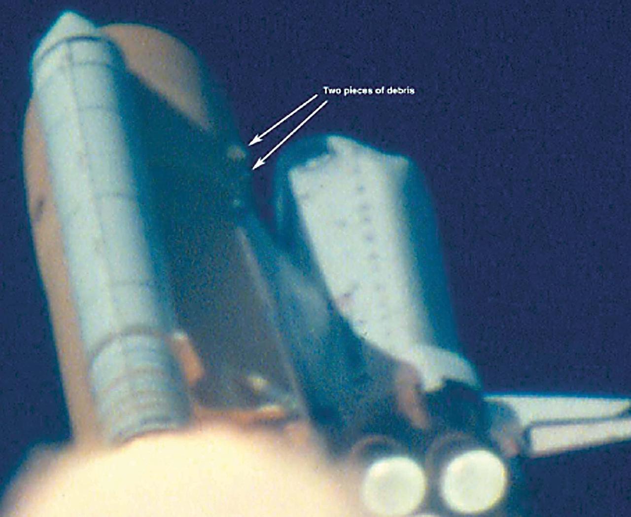
KENNEDY SPACE CENTER, FLA. - At approximately 81-82 seconds after T-0 and liftoff of Space Shuttle Columbia, debris originating from the area near the external tank -Y bipod strut attachpoint is observed striking the underside of the LH wing of the orbiter. The impact site appears to be near the leading edge of the wing. Damage assessment is difficult due to poor resolution and analysis is continuing on this event.
Researchers test a 10-foot Mock Truss-Braced Wing at NASA’s Armstrong Flight Research Center in Edwards, California. Samson Truong, from left, and Ben Park, NASA mock wing ground vibration test director, prepare for a vibration test. The aircraft concept involves a wing braced on an aircraft using diagonal struts that also add lift and could result in significantly improved aerodynamics.

CAPE CANAVERAL, Fla. -- In Orbiter Processing Facility Bay 3 at NASA’s Kennedy Space Center, Jerry McKlin (left) and Milan Vasic, with United Space Alliance, check the placement under space shuttle Discovery of the struts from the Orbiter Transport System, or OTS. The OTS will help move the orbiter on its rollover to the Vehicle Assembly Building. Discovery is targeted to launch May 31 on the STS-124 mission to the International Space Station. On the mission, Discovery will transport the Kibo Japanese Experiment Module - Pressurized Module (JEM-PM) and the Japanese Remote Manipulator System (JEM-RMS) to the space station to add to the Kibo laboratory. Photo credit: NASA/Troy Cryder
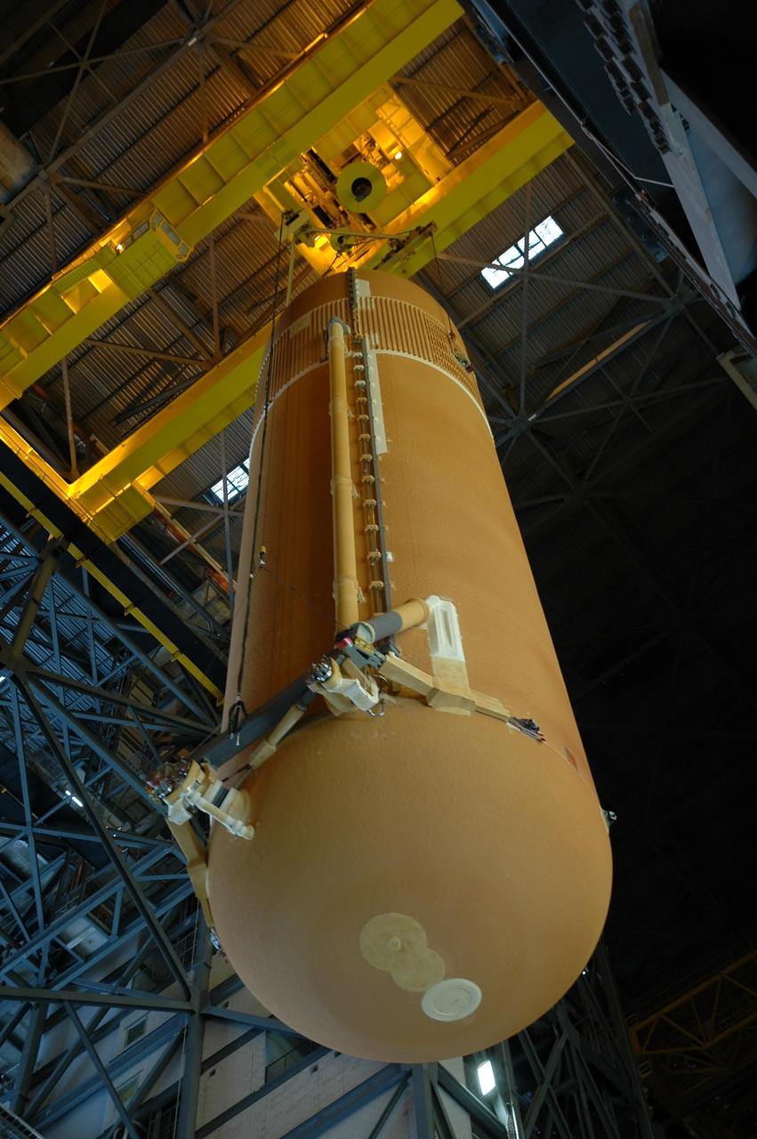
KENNEDY SPACE CENTER, FLA. -- Inside the Vehicle Assembly Building, the external tank for Endeavour is being lowered toward the mobile launcher platform for mating with the solid rocket boosters. Endeavour is currently targeted for rollover to the VAB July 5. On the lower end of the tank is seen the bipod fittings that connect the external tank to the orbiter through the shuttle's two forward attachment struts. Endeavour is the designated orbiter for mission STS-118, targeted for launch on Aug. 9 to the International Space Station. The mission will continue space station construction by delivering a third starboard truss segment, S5, as well as carrying the external stowage platform 3. Photo credit: NASA/Amanda Diller
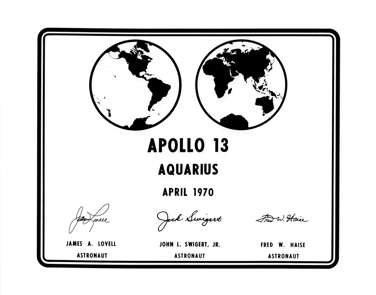
S70-34685 (April 1970) --- A photographic replica of the plaque which the Apollo 13 astronauts will leave behind on the moon during their lunar landing mission. Astronauts James A. Lovell Jr., commander; and Fred W. Haise Jr., lunar module pilot, will descend to the lunar surface in the Lunar Module (LM) "Aquarius". Astronaut John L. Swigert Jr., command module pilot, will remain with the Command and Service Modules (CSM) in lunar orbit. The plaque will be attached to the ladder of the landing gear strut on the LM?s descent stage. Commemorative plaques were also left on the moon by the Apollo 11 and Apollo 12 astronauts.
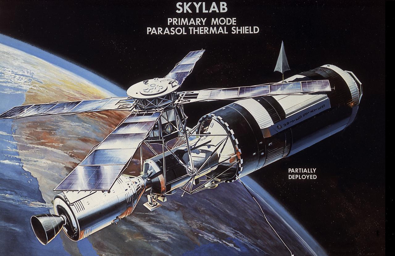
This image illustrates the deployment of the Skylab parasol thermal shield. Skylab lost its thermal protection shield during its launch on May 14, 1973. The Skylab-2 crew deployed a parasol thermal shield to protect the workshop from overheating. The crew attached the canister containing the parasol to the scientific airlock and extended the folded shield through the opening and into space. Slowly, the struts extended and the sunshade took shape and was in place over the workshop's outer surface. This illustration shows the parasol at partial extension. Emergency procedures to repair and salvage the damaged Skylab were a joint effort of the Marshall Space Flight Center, other NASA centers, and contractors.
STS-49, the first flight of the Space Shuttle Orbiter Endeavour, lifted off from launch pad 39B on May 7, 1992 at 6:40 pm CDT. The STS-49 mission was the first U.S. orbital flight to feature 4 extravehicular activities (EVAs), and the first flight to involve 3 crew members working simultaneously outside of the spacecraft. The primary objective was the capture and redeployment of the INTELSAT VI (F-3) which was stranded in an unusable orbit since its launch aboard the Titan rocket in March 1990. In this STS-49 onboard photo, Astronaut Kathryn Thornton joins three struts together during her Extra Vehicular Activity (EVA).
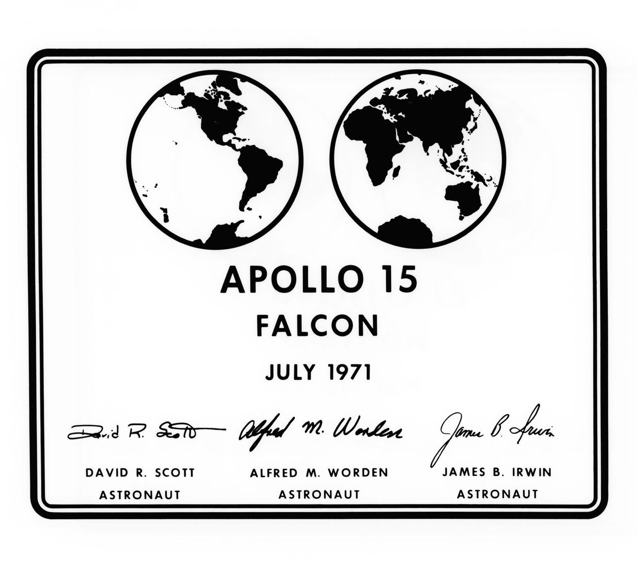
S71-39357 (July 1971) --- A photographic replica of the plaque which the Apollo 15 astronauts will leave behind on the moon during their lunar landing mission. Astronauts David R. Scott, commander; and James B. Irwin, lunar module pilot; will descend to the lunar surface in the Lunar Module (LM) "Falcon". Astronaut Alfred M. Worden, command module pilot, will remain with the Command and Service Modules (CSM) in lunar orbit. The seven by nine inch stainless steel plaque will be attached to the ladder on the landing gear strut on the LM's descent stage. Commemorative plaques were also left on the moon by the Apollo 11, Apollo 12 and Apollo 14 astronauts.
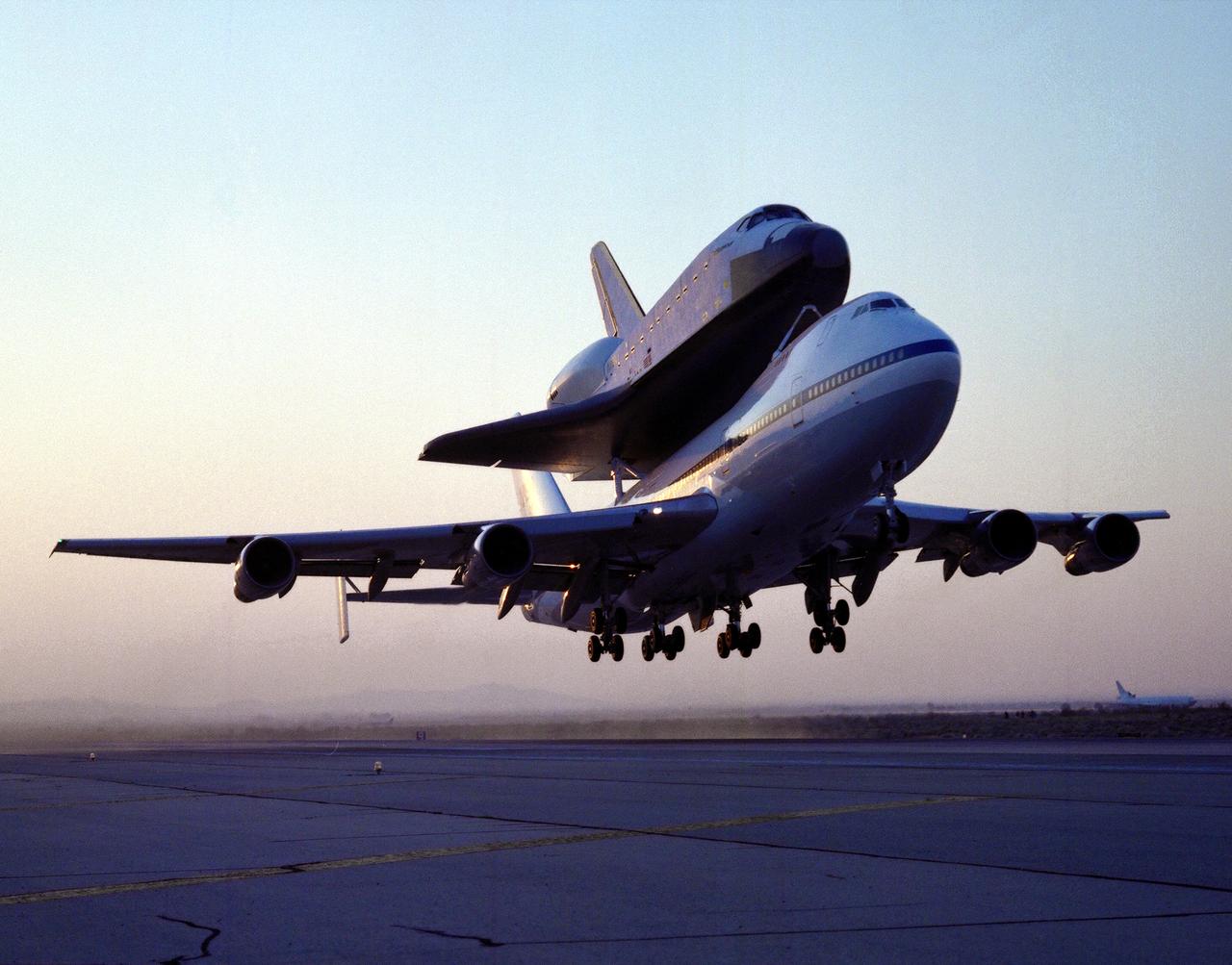
NASA's 747 Shuttle Carrier Aircraft No. 911, with the space shuttle orbiter Endeavour securely mounted atop its fuselage, begins the ferry flight from Rockwell's Plant 42 at Palmdale, California, where the orbiter was built, to the Kennedy Space Center, Florida. At Kennedy, the space vehicle was processed and launched on orbital mission STS-49, which landed at NASA's Ames-Dryden Flight Research Facility (later redesignated Dryden Flight Research Center), Edwards, California, 16 May 1992. NASA 911, the second modified 747 that went into service in November 1990, has special support struts atop the fuselage and internal strengthening to accommodate the added weight of the orbiters.