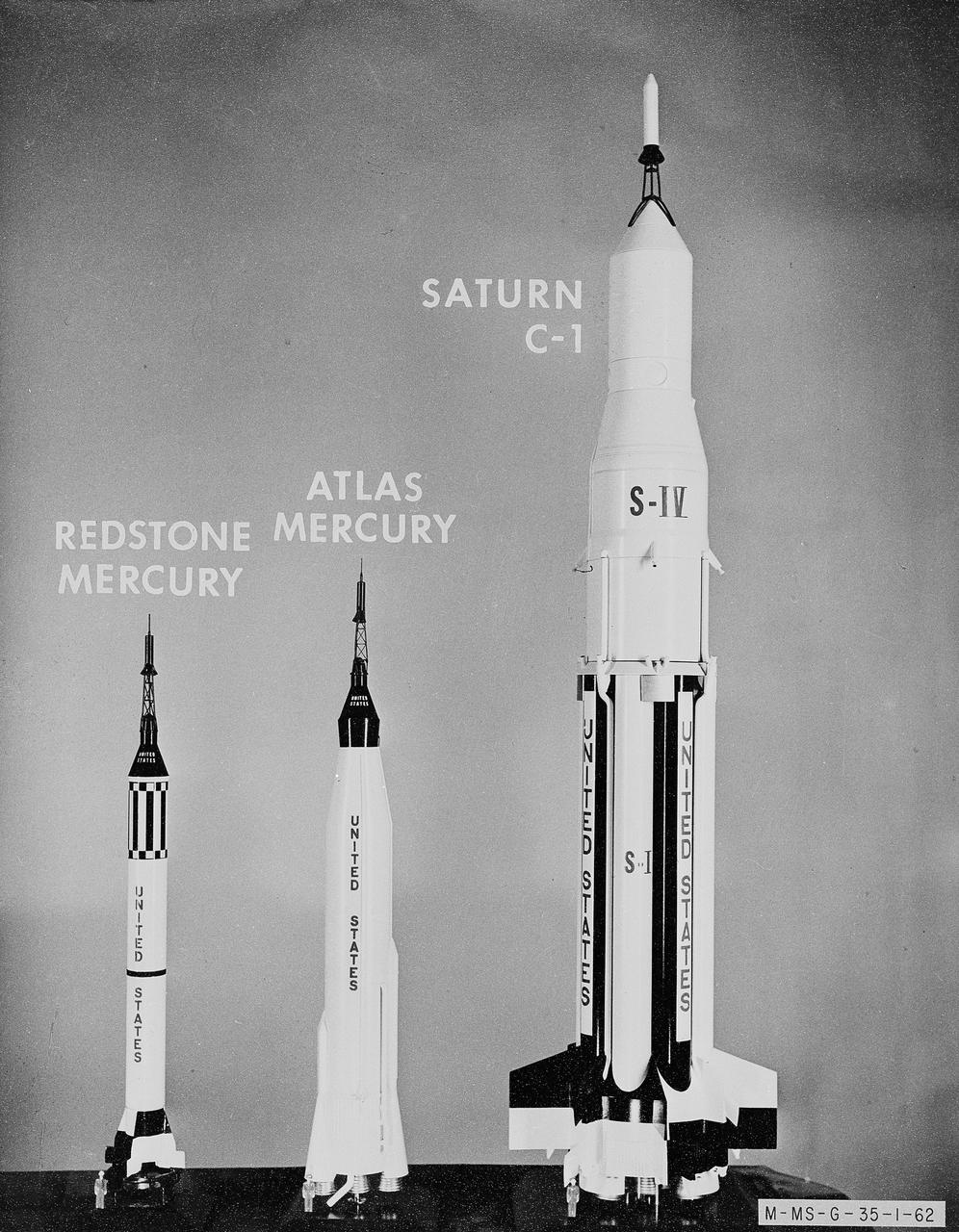
Photographed are models of early rocketry: The Atlas Mercury, Redstone Mercury; and Saturn C-1.
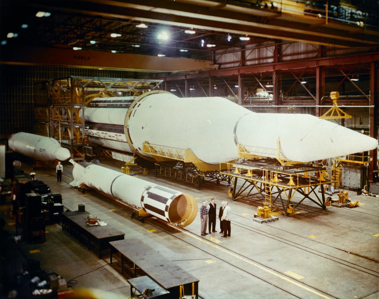
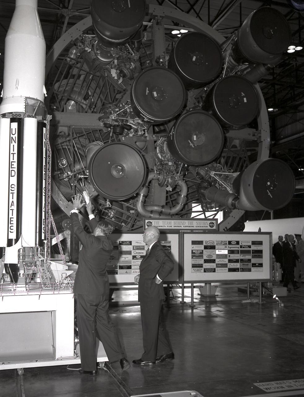
Progress in the Saturn program, depicted below, was described by Dr. Wernher von Braun, Marshall Space Flight Center (MSFC) Director, in an appearance before the Senate Committee of Aeronautical and Space Sciences. "The flight configuration of the giant three-stage Saturn C-1 rocket (later called Saturn I Block I) is seen in the Fabrication and Assembly Engineering Division at MSFC. Dwarfed by the 180-foot C-1 are a Juno II rocket (left rear) and a Mercury-Redstone rocket (front foreground). The C-1 (first version of the Saturn rocket) is composed of an S-1 first stage or booster (rear), powered by eight H-1 engines having a thrust of 1,500,000 pounds, followed by a dummy S-IV second stage and a dummy S-V third stage. The "live" S-IV for later flights, under development by Douglas Aircraft Co., will be powered by four Pratt Whitney LR-119 engines having 17,500,000 pounds thrust each. The live S-V, under development by Convair Division of General Dynamics Corp., will use two LR-119 engines. With all three stages live, the C-1 will be capable of placing 19,000 pounds into a 300-mile Earth orbit, sending 5,000 pounds to escape velocity, or lofting 2,500 pounds to Mars or Venus. The second version Saturn C-2 (later called Saturn 1 Block II) would double these capabilities. Early C-1 flights will employ a live S-1 with dummy upper stages. The first such flight is scheduled late this year."
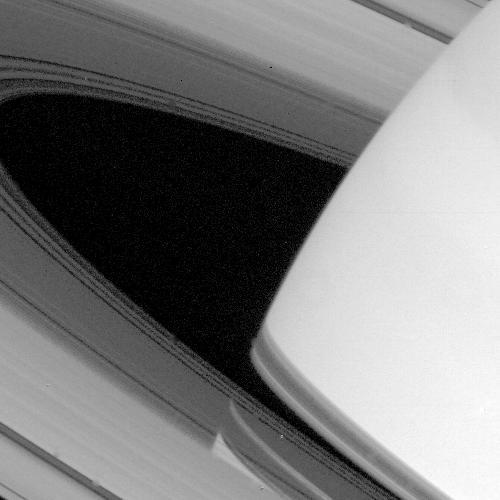
Both the limb of Saturn and the shadow of its ring system are seen through the transparent C-ring in this striking picture taken by NASA Voyager 1 on Nov. 9, 1980. Gaps and regions of high transparency are seen throughout the C-ring, especially in the a
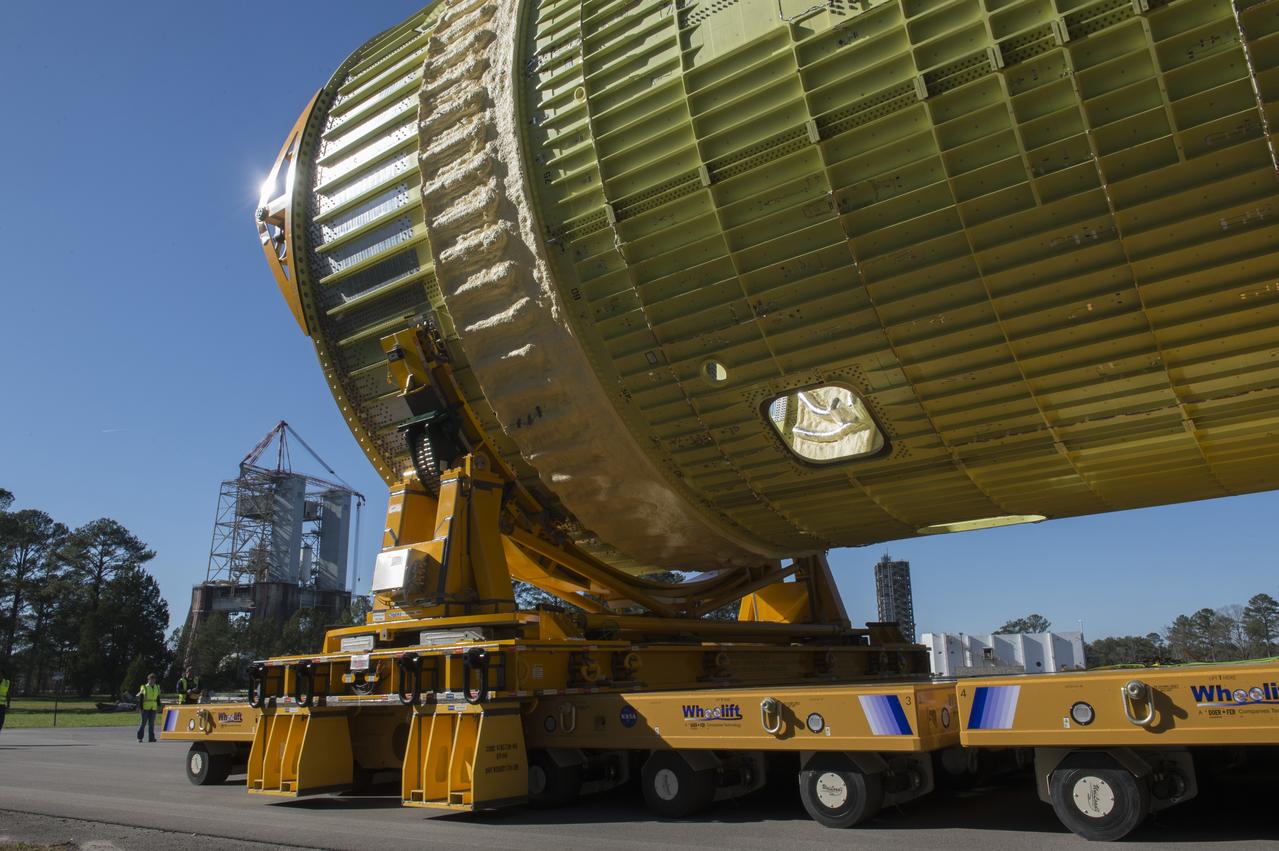
The SLS Stages Intertank Structural Test Assembly (STA) is rolling off the NASA Pegasus Barge at the MSFC Dock enroute to the MSFC 4619 Load Test Annex test facility for qualification testing via MSFC West Test Area. Historic Saturn 1-C test stand on far left, blockhouse 4670 on far right, SLS LH2 test stand, 4693, in center.
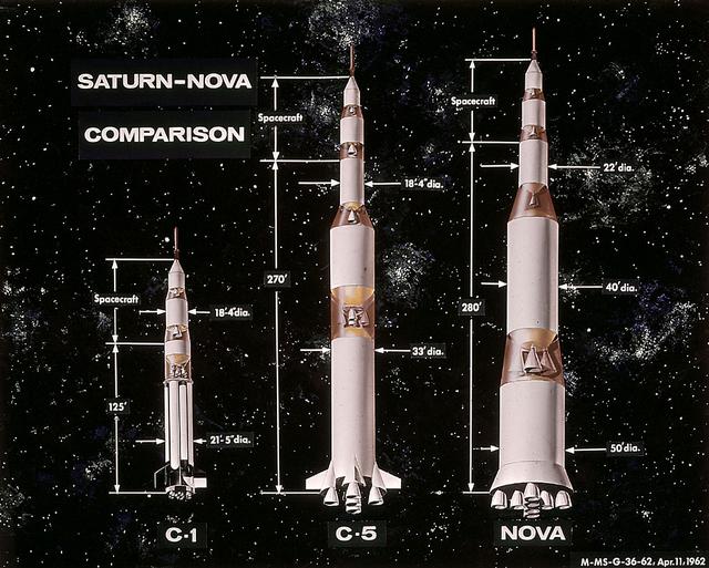
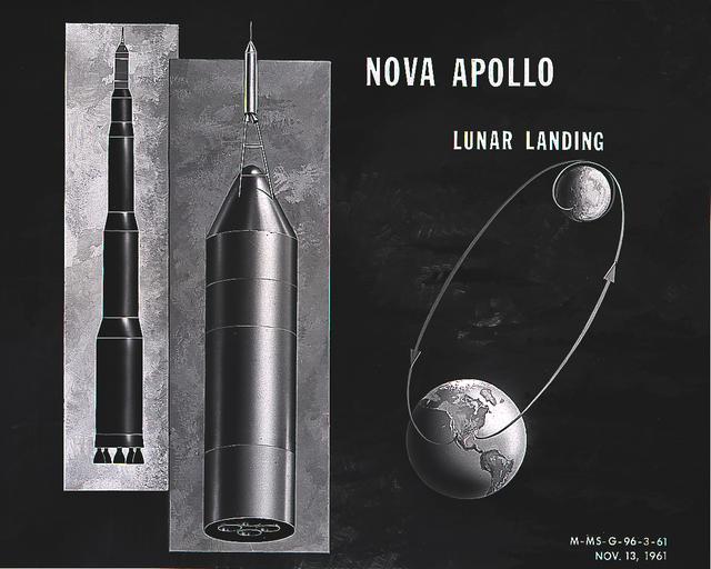
In this 1962 artist's concept , a proposed Nova rocket, shown at right, is compared to a Saturn C-1, left, and a Saturn C-5, center. The Marshall Space Flight Center directed studies of Nova configuration from 1960 to 1962 as a means of achieving a marned lunar landing with a direct flight to the Moon. Various configurations of the vehicle were examined, the largest being a five-stage vehicle using eight F-1 engines in the first stage. Although the program was effectively cancelled in 1962 when NASA planners selected the lunar-orbital rendezvous mode, the proposed F-1 engine was eventually used to propel the first stage of the Saturn V launch vehicle in the Apollo Program.
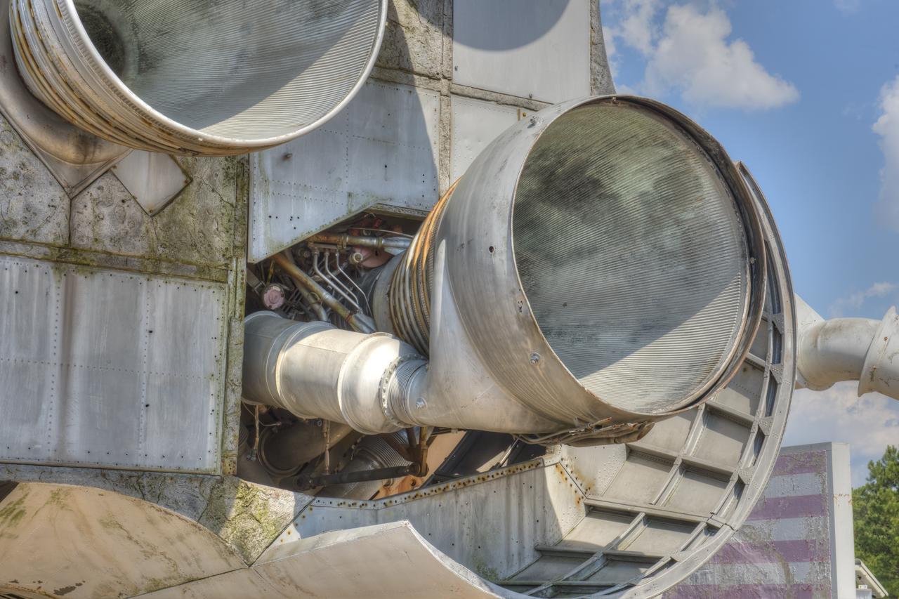
CLOSE-UP OF H-1 ENGINE INSTALLED ON SATURN S-1B STAGE (SA-T) NEAR PROPULSION AND STRUCTURAL TEST FACILITY (BUILDING 4572) AT THE GEORGE C. MARSHALL SPACE FLIGHT CENTER.
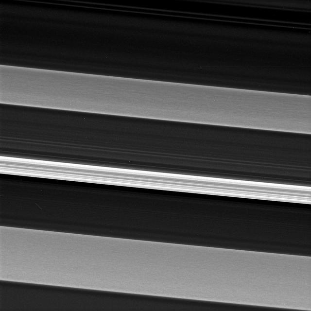
Saturn's C ring is home to a surprisingly rich array of structures and textures. Much of the structure seen in the outer portions of Saturn's rings is the result of gravitational perturbations on ring particles by moons of Saturn. Such interactions are called resonances. However, scientists are not clear as to the origin of the structures seen in this image which has captured an inner ring region sparsely populated with particles, making interactions between ring particles rare, and with few satellite resonances. In this image, a bright and narrow ringlet located toward the outer edge of the C ring is flanked by two broader features called plateaus, each about 100 miles (160 kilometers) wide. Plateaus are unique to the C ring. Cassini data indicates that the plateaus do not necessarily contain more ring material than the C ring at large, but the ring particles in the plateaus may be smaller, enhancing their brightness. This view looks toward the sunlit side of the rings from about 53 degrees above the ring plane. The image was taken in green light with the Cassini spacecraft narrow-angle camera on Aug. 14, 2017. The view was acquired at a distance of approximately 117,000 miles (189,000 kilometers) from Saturn and at a Sun-Saturn-spacecraft, or phase, angle of 74 degrees. Image scale is 3,000 feet (1 kilometer) per pixel. The Cassini spacecraft ended its mission on Sept. 15, 2017. https://photojournal.jpl.nasa.gov/catalog/PIA21356
Dr. von Braun briefs President Eisenhower at the front of the S1 Stage (first Stage) of the Saturn 1 vehicle at the Marshall Space Flight Center (MSFC) on September 8, 1960. The President's visit was to dedicate Marshall Space Flight Center as a new NASA field center in honor of General George C. Marshall.
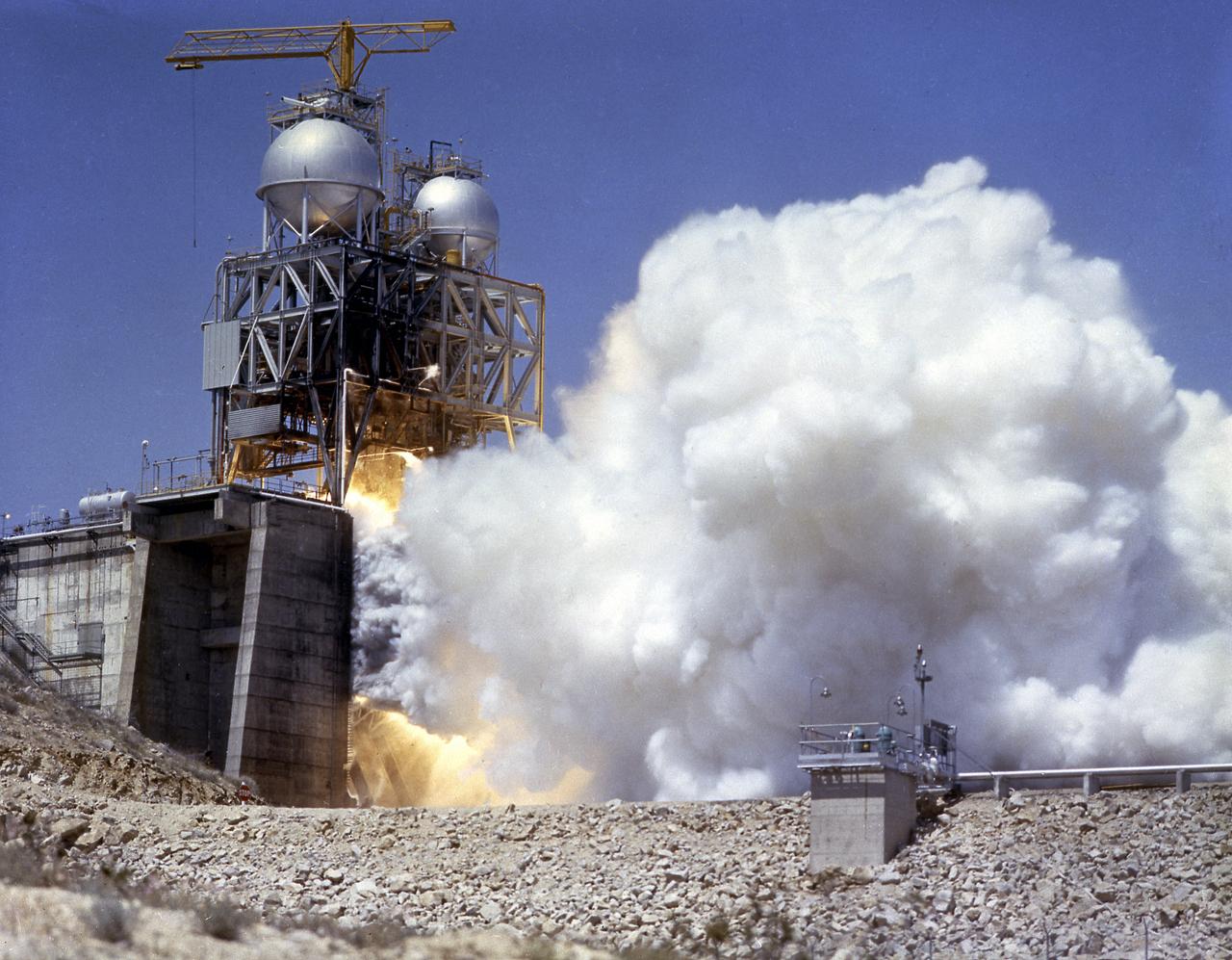
This photograph depicts the Rocketdyne static firing of the F-1 engine at the towering 76-meter Test Stand 1-C in Area 1-125 of the Edwards Air Force Base in California. The Saturn V S-IC (first) stage utilized five F-1 engines for its thrust. Each engine provided 1,500,000 pounds, for a combined thrust of 7,500,000 pounds with liquid oxygen and kerosene as its propellants.
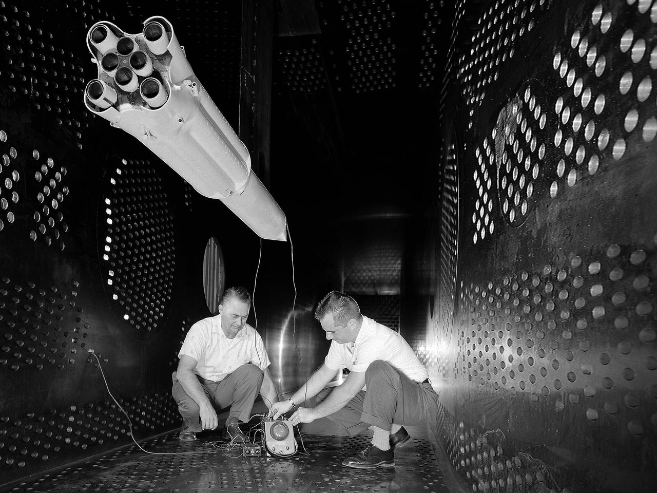
National Aeronautics and Space Administration (NASA) researchers set up instrumentation on a 0.037- scale model of a Saturn booster in the 8- by 6-Foot Supersonic Wind Tunnel at the NASA Lewis Research Center. In October 1960 Lewis researchers John Allen and Robert Wasko began a 14-month investigation of the eight-engine booster’s base heating in the tunnel. The model resembled the Saturn C-1, but only the afterbody totally mimicked the C-1. The over-heating of the lower end, or base, of the booster can cause the engines to fail or introduce aerodynamic concerns. Base heating results from the rocket engines’ exhaust heat, the recirculation of that heat into the base, and the burning of combustibles. Large boosters, like the Saturn, employed clusters of rocket engines that add to the complexity of the base heating problem. The 8- by 6-foot tunnel investigations studied the Saturn at speeds from Mach 1.0 to 2.0 using liquid oxygen and JP-4 as propellants. Researchers found that the use of cooling air scoops and external flow deflectors produced significant decreases in base heating.
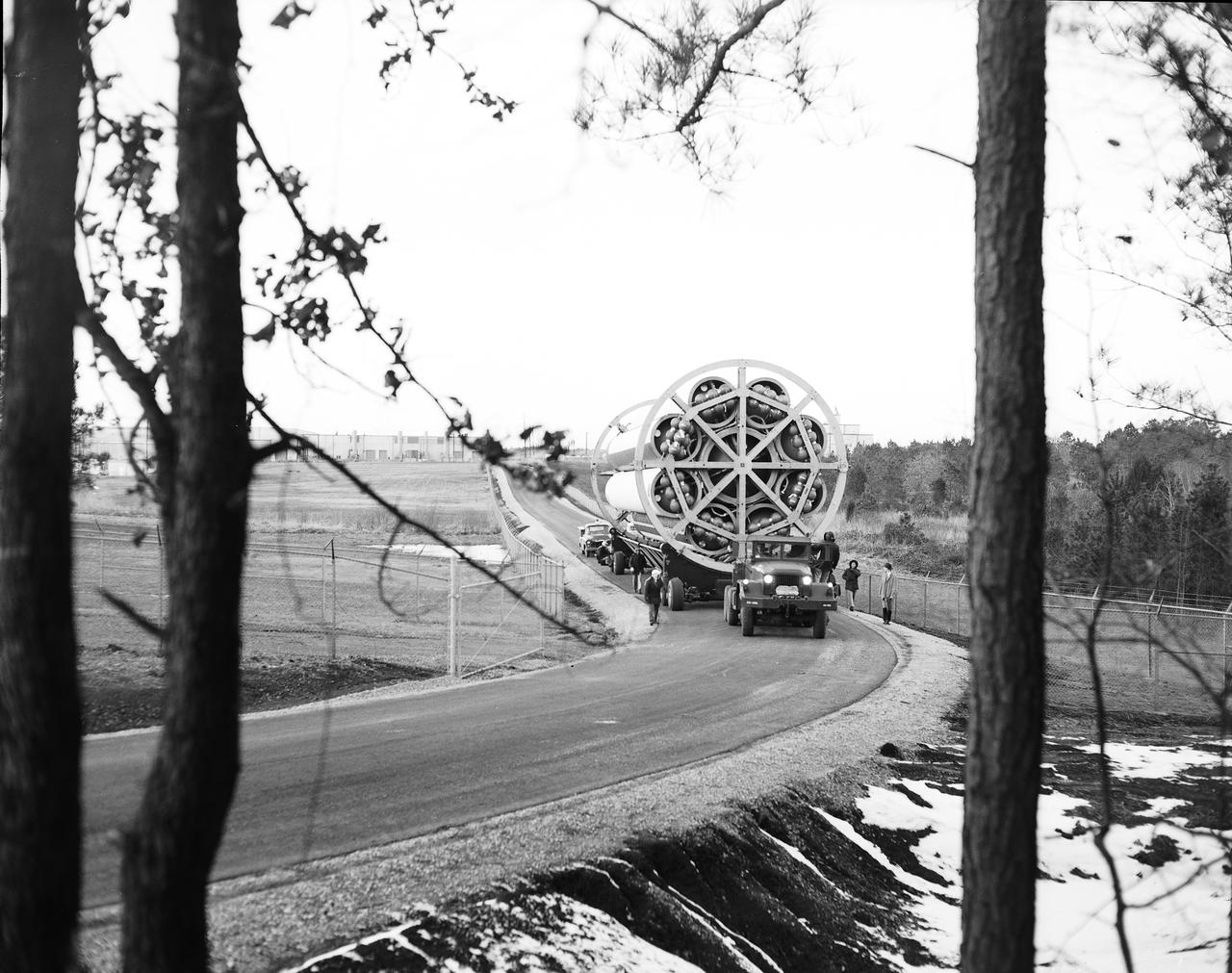
The fuel tank assembly of the Saturn V S-IC (first) stage supported with the aid of a C frame on the transporter was readied to be transported to the Marshall Space Flight Center, building 4705. The fuel tank carried kerosene (RP-1) as its fuel. The S-IC stage utilized five F-1 engines that used kerosene and liquid oxygen as propellant and each engine provided 1,500,000 pounds of thrust. This stage lifted the entire vehicle and Apollo spacecraft from the launch pad.
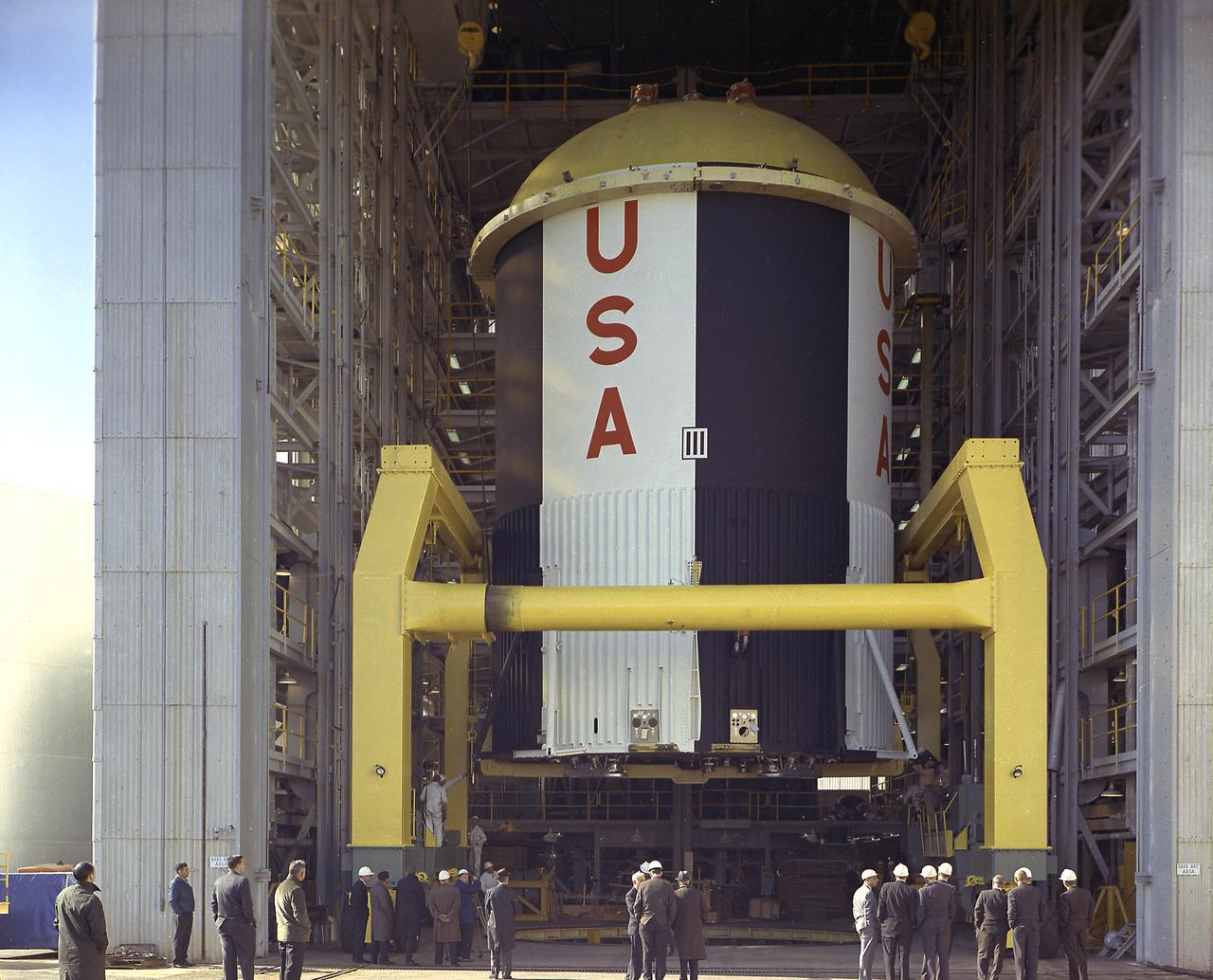
This photograph shows the Saturn-I first stage (S-1 stage) being transported to the test stand for a static test firing at the Marshall Space Flight Center. Soon after NASA began operations in October 1958, it was evident that sending people and substantial equipment beyond the Earth's gravitational field would require launch vehicles with weight-lifting capabilities far beyond any developed to that time. In early 1959, NASA accepted the proposal of Dr. Wernher von Braun for a multistage rocket, with a number of engines clustered in one or more of the stages to provide a large total thrust. The initiation of the Saturn launch vehicle program ultimately led to the study and preliminary plarning of many different configurations and resulted in production of three Saturn launch vehicles, the Saturn-I, Saturn I-B, and Saturn V. The Saturn family of launch vehicles began with the Saturn-I, a two-stage vehicle originally designated C-1. The research and development program was planned in two phases, or blocks: one for first stage development (Block I) and the second for both first and second stage development (Block-II). Saturn I had a low-earth-orbit payload capability of approximately 25,000 pounds. The design of the first stage (S-1 stage) used a cluster of propellant tanks containing liquid oxygen (LOX) and kerosene (RP-1), and eight H-1 engines, yielding a total thrust of 1,500,000 pounds. Of the ten Saturn-Is planned, the first eight were designed and built at the Marshall Space Flight Center, and the remaining two were built by the Chrysler Corporation.

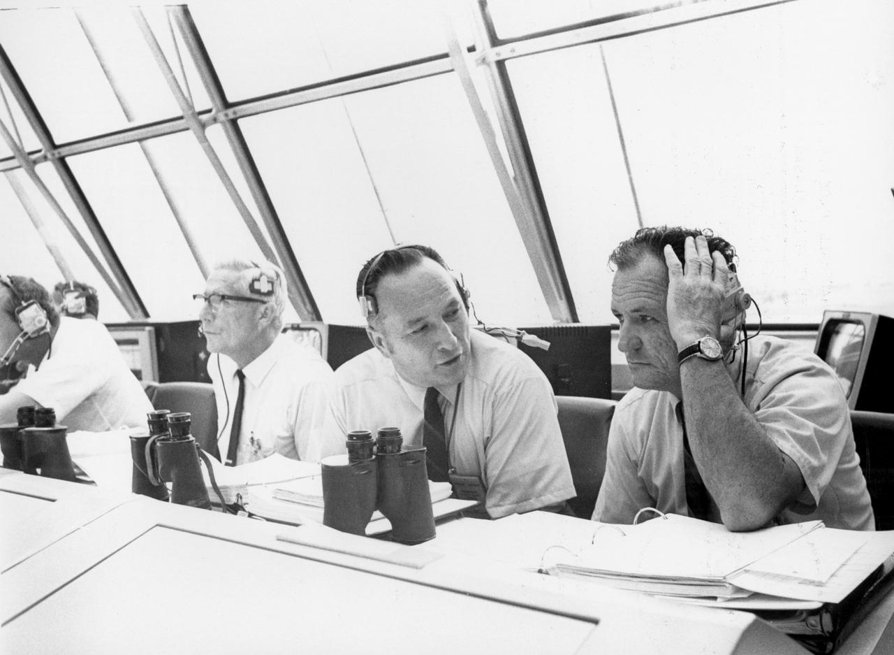
S68-18733 (22 Jan. 1968) --- Dr. Robert R. Gilruth (right), MSC Director, sits with Dr. Christopher C. Kraft Jr., MSC director of flight operations, at his flight operations director console in the Mission Control Center, Building 30, during the Apollo 5 (LM-1/Saturn 204) unmanned space mission.
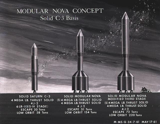
This artist's concept illustrates the Module Nova concept - Solid C-3 Basis. From 1960 to 1962, the Marshall Space Flight Center considered the Nova launch vehicle as a means to achieve a marned lunar landing with a direct flight to the Moon. Various configurations of the vehicle were examined. The latest configuration was a five-stage vehicle using eight F-1 engines in the first stage. Although the program was canceled after NASA planners selected the lunar/orbital rendezvous mode, the proposed F-1 engine would eventually be used in the Apollo Program to propel the first stage of the Saturn V launch vehicle.
This artist's concept illustrates the Module Nova concept - Solid C-3 Basis. From 1960 to 1962, the Marshall Space Flight Center considered the Nova launch vehicle as a means to achieve a marned lunar landing with a direct flight to the Moon. Various configurations of the vehicle were examined. The latest configuration was a five-stage vehicle using eight F-1 engines in the first stage. Although the program was canceled after NASA planners selected the lunar/orbital rendezvous mode, the proposed F-1 engine would eventually be used in the Apollo Program to propel the first stage of the Saturn V launch vehicle.
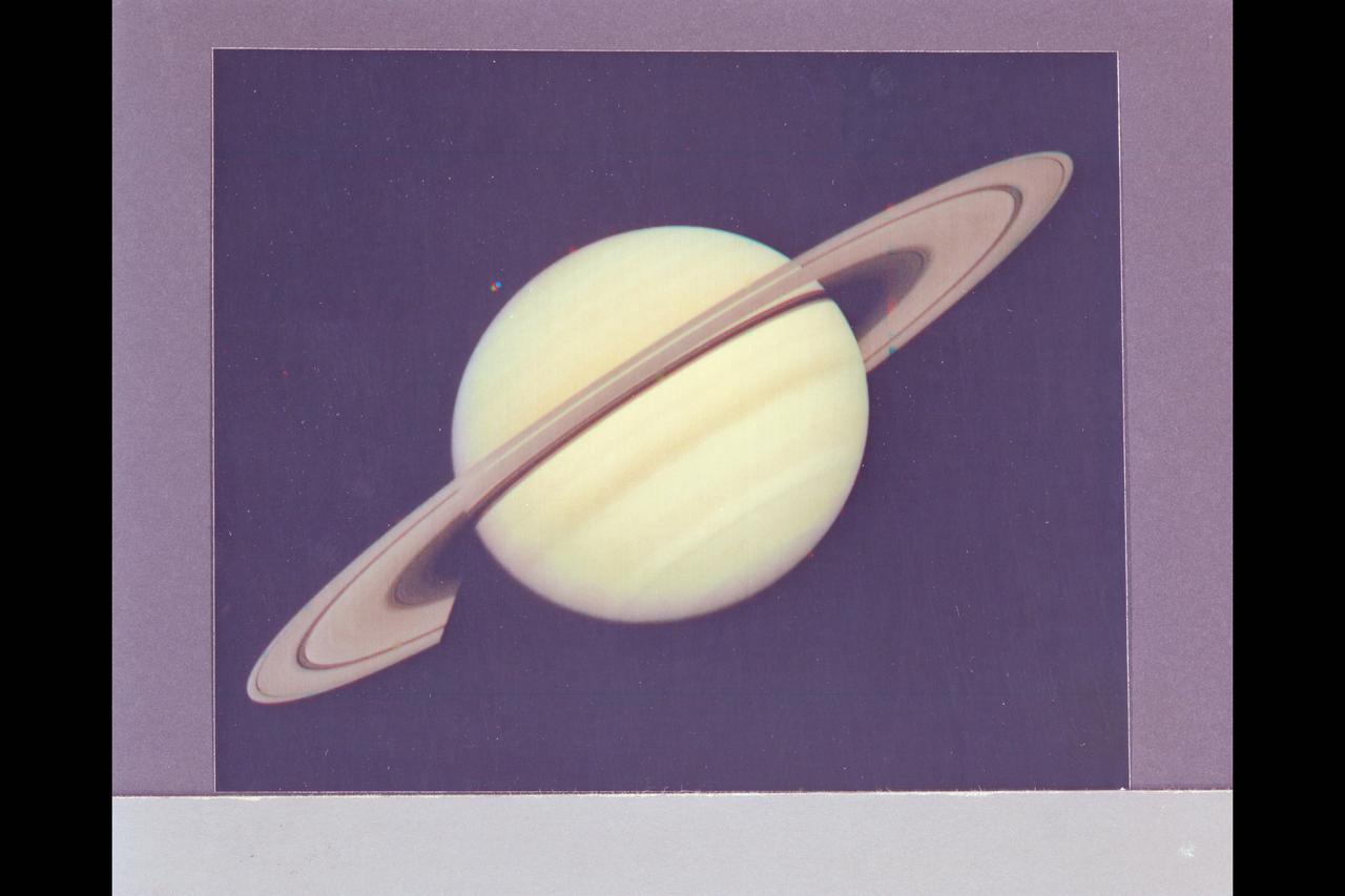
Range : 34 million km. ( 21.1 million miles) P-22993C This Voyager 1 photograph of Saturn was taken on the last day it could be captured within a single narrow angle camera frame as the spacecraft neared the planet for it's closest approach on Nov. 12, 1980. Dione, one of Saturn's innermost satellites, appears as three color spots just below the planet's south pole. An abundance of previously unseen detail is apparent in the rings. For example, a gap in the dark, innermst ring, C-ring or Crepe Ring, is clearly shown. Also, material is seen inside the relatively wide Cassini Division, seperating the middle, B-ring from the outermost ring, the A-ring. The Encke division is shown near the outer edge of A-ring. The detail in the ring's shadows cast on the planet is of particular interest. The broad dark band near the equator is the shadow of B-ring. The thinner, brighter line just to the south is the shadow of the less dense A-ring.
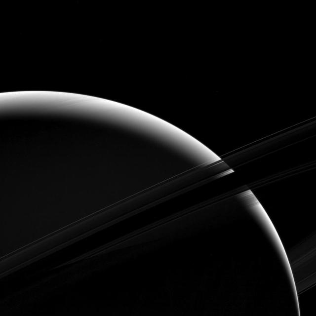
Although only a sliver of Saturn's sunlit face is visible in this view, the mighty gas giant planet still dominates the view. From this vantage point just beneath the ring plane, the dense B ring becomes dark and essentially opaque, letting almost no light pass through. But some light reflected by the planet passes through the less dense A ring, which appears above the B ring in this photo. The C ring, silhouetted just below the B ring, lets almost all of Saturn's reflected light pass right through it, as if it were barely there at all. The F ring appears as a bright arc in this image, which is visible against both the backdrop of Saturn and the dark sky. This view looks toward the unilluminated side of the rings from about 7 degrees below the ring plane. The image was taken in green light with the Cassini spacecraft wide-angle camera on Jan. 18, 2017. The view was acquired at a distance of approximately 630,000 miles (1 million kilometers) from Saturn. Image scale is 38 miles (61 kilometers) per pixel. https://photojournal.jpl.nasa.gov/catalog/PIA20530
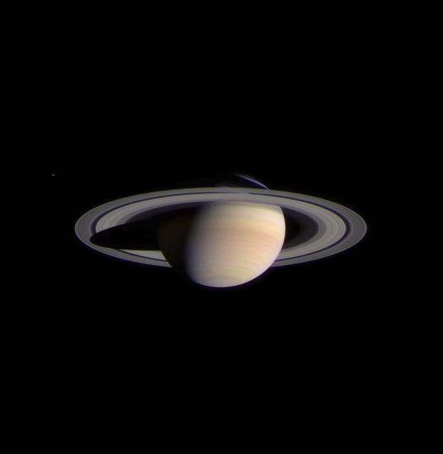
The narrow angle camera onboard NASA's Cassini spacecraft took a series of exposures of Saturn and its rings and moons on February 9, 2004, which were composited to create this stunning, color image. At the time, Cassini was 69.4 million kilometers (43.1 million miles) from Saturn, less than half the distance from Earth to the Sun. The image contrast and colors have been slightly enhanced to aid visibility. The smallest features visible in this image are approximately 540 kilometers across (336 miles). Fine details in the rings and atmosphere are beginning to emerge, and will grow in sharpness and clarity over the coming months. The optical thickness of Saturn's B (middle) ring and the comparative translucence of the A (outer) ring, when seen against the planet, are now apparent. Subtle color differences in the finely banded Saturnian atmosphere, as well as structure within the diaphanous, inner C ring can be easily seen. Noticeably absent are the ghostly spoke-like dark markings in Saturn's B ring, first discovered by NASA's Voyager spacecraft on approach to the planet 23 years ago. The icy moon Enceladus (520 kilometers or 323 miles across) is faintly visible on the left in the image. Its brightness has been increased seven times relative to the planet. Cassini will make several very close approaches to Enceladus, returning images in which features as small as 50 meters (165 feet) or less will be detectable. The composite image signals the start of Cassini's final approach to the ringed planet and the beginning of monitoring and data collection on Saturn and its environment. This phase of the mission will continue until Cassini enters orbit around Saturn on July 1, 2004. http://photojournal.jpl.nasa.gov/catalog/PIA05380
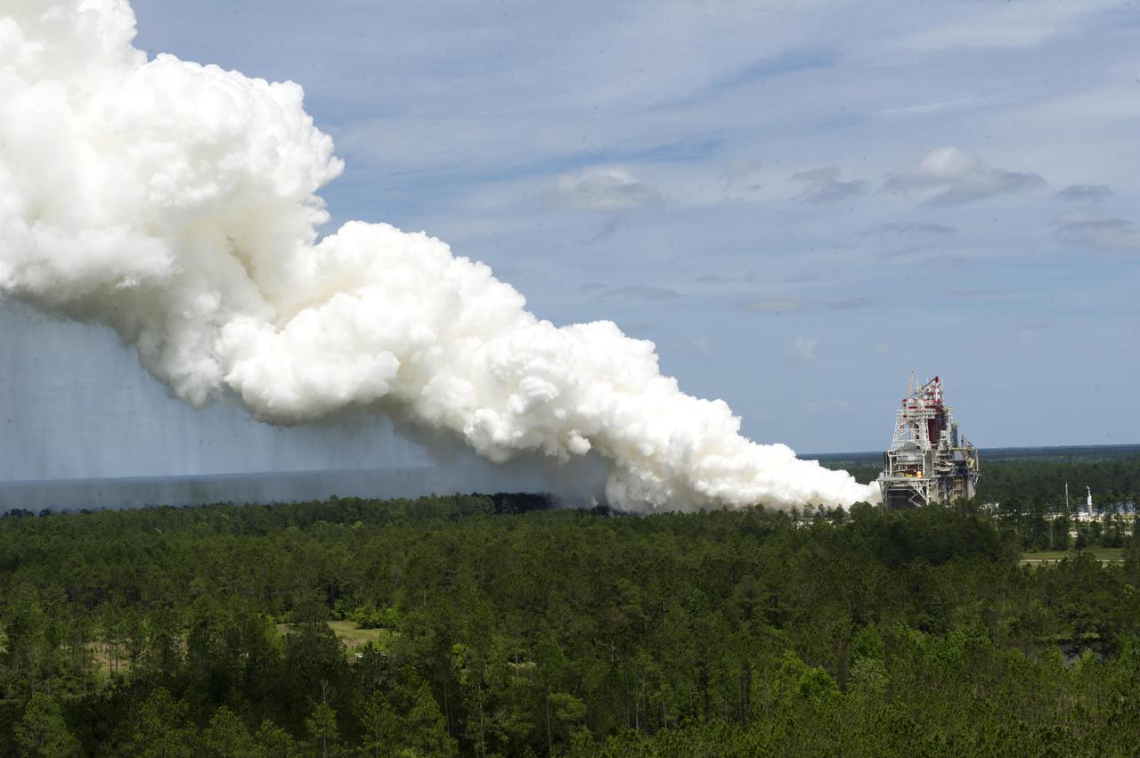
What better way to mark 50 years of rocket engine testing than with a rocket engine test? Stennis Space Center employees enjoyed a chance to view an RS-68 engine test at the B-1 Test Stand on April 19, almost 50 years to the day that the first test was conducted at the south Mississippi site in 1966. The test viewing was part of a weeklong celebration of the 50th year of rocket engine testing at Stennis. The first test at the site occurred April 23, 1966, with a 15-second firing of a Saturn V second stage prototype (S-II-C) on the A-2 Test Stand. The center subsequently tested Apollo rocket stages that carried humans to the moon and every main engine used to power 135 space shuttle missions. It currently tests engines for NASA’s new Space Launch System vehicle.
Lee B. James (left), manager of the Saturn Program at the Marshall Space flight Center (MSFC), talks with Isom Pigell in the firing room 1 of the Kennedy Space Center (KSC) control center during the countdown demonstration test for the Apollo 11 mission. At left is Dr. Hans C. Gruen of KSC. The Apollo 11 mission, the first lunar landing mission, launched from the KSC in Florida via the MSFC developed Saturn V launch vehicle on July 16, 1969 and safely returned to Earth on July 24, 1969. Aboard the space craft were astronauts Neil A. Armstrong, commander; Michael Collins, Command Module (CM) pilot; and Edwin E. (Buzz) Aldrin Jr., Lunar Module (LM) pilot. The CM, “Columbia”, piloted by Collins, remained in a parking orbit around the Moon while the LM, “Eagle’’, carrying astronauts Armstrong and Aldrin, landed on the Moon. On July 20, 1969, Armstrong was the first human to ever stand on the lunar surface, followed by Aldrin. During 2½ hours of surface exploration, the crew collected 47 pounds of lunar surface material for analysis back on Earth. With the success of Apollo 11, the national objective to land men on the Moon and return them safely to Earth had been accomplished.

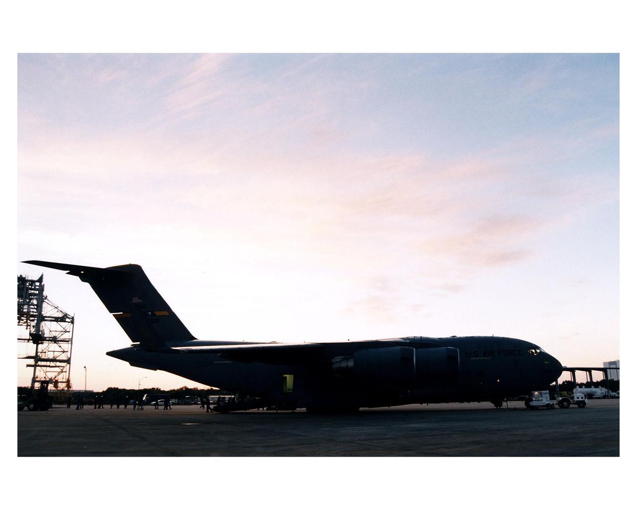
Workers offload the shipping container with the Cassini orbiter from what looks like a giant shark mouth, but is really an Air Force C-17 air cargo plane which <a href="http://www-pao.ksc.nasa.gov/kscpao/release/1997/66-97.htm">just landed</a> at KSC’s Shuttle Landing Facility from Edwards Air Force Base, California. The orbiter and the Huygens probe already being processed at KSC are the two primary components of the Cassini spacecraft, which will be launched on a Titan IVB/Centaur expendable launch vehicle from Cape Canaveral Air Station. Cassini will explore Saturn, its rings and moons for four years. The Huygens probe, designed and developed for the European Space Agency (ESA), will be deployed from the orbiter to study the clouds, atmosphere and surface of Saturn’s largest moon, Titan. The orbiter was designed and assembled at NASA’s Jet Propulsion Laboratory in California. Following postflight inspections, integration of the 12 science instruments not already installed on the orbiter will be completed. Then, the parabolic high-gain antenna and the propulsion module will be mated to the orbiter, followed by the Huygens probe, which will complete spacecraft integration. The Cassini mission is targeted for an Oct. 6 launch to begin its 6.7-year journey to the Saturnian system. Arrival at the planet is expected to occur around July 1, 2004
Workers begin unloading the Cassini orbiter from a U.S. Air Force C-17 air cargo plane after its <a href="http://www-pao.ksc.nasa.gov/kscpao/release/1997/66-97.htm">arrival</a> at KSC’s Shuttle Landing Facility from Edwards Air Force Base, California. The orbiter and the Huygens probe already being processed at KSC are the two primary components of the Cassini spacecraft, which will be launched on a Titan IVB/Centaur expendable launch vehicle from Cape Canaveral Air Station. Cassini will explore Saturn, its rings and moons for four years. The Huygens probe, designed and developed for the European Space Agency (ESA), will be deployed from the orbiter to study the clouds, atmosphere and surface of Saturn’s largest moon, Titan. The orbiter was designed and assembled at NASA’s Jet Propulsion Laboratory in California. Following postflight inspections, integration of the 12 science instruments not already installed on the orbiter will be completed. Then, the parabolic high-gain antenna and the propulsion module will be mated to the orbiter, followed by the Huygens probe, which will complete spacecraft integration. The Cassini mission is targeted for an Oct. 6 launch to begin its 6.7-year journey to the Saturnian system. Arrival at the planet is expected to occur around July 1, 2004
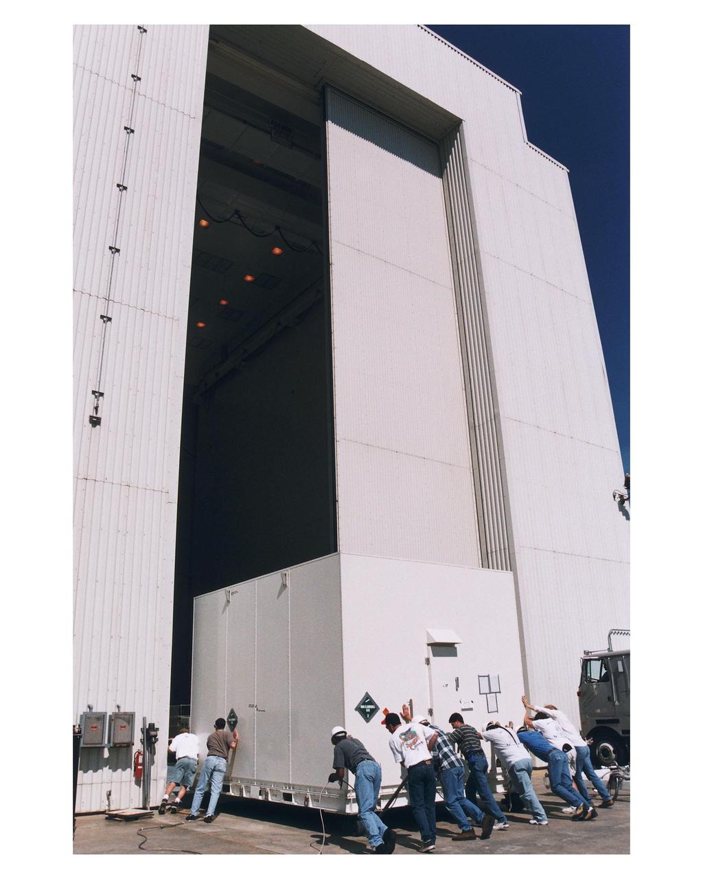
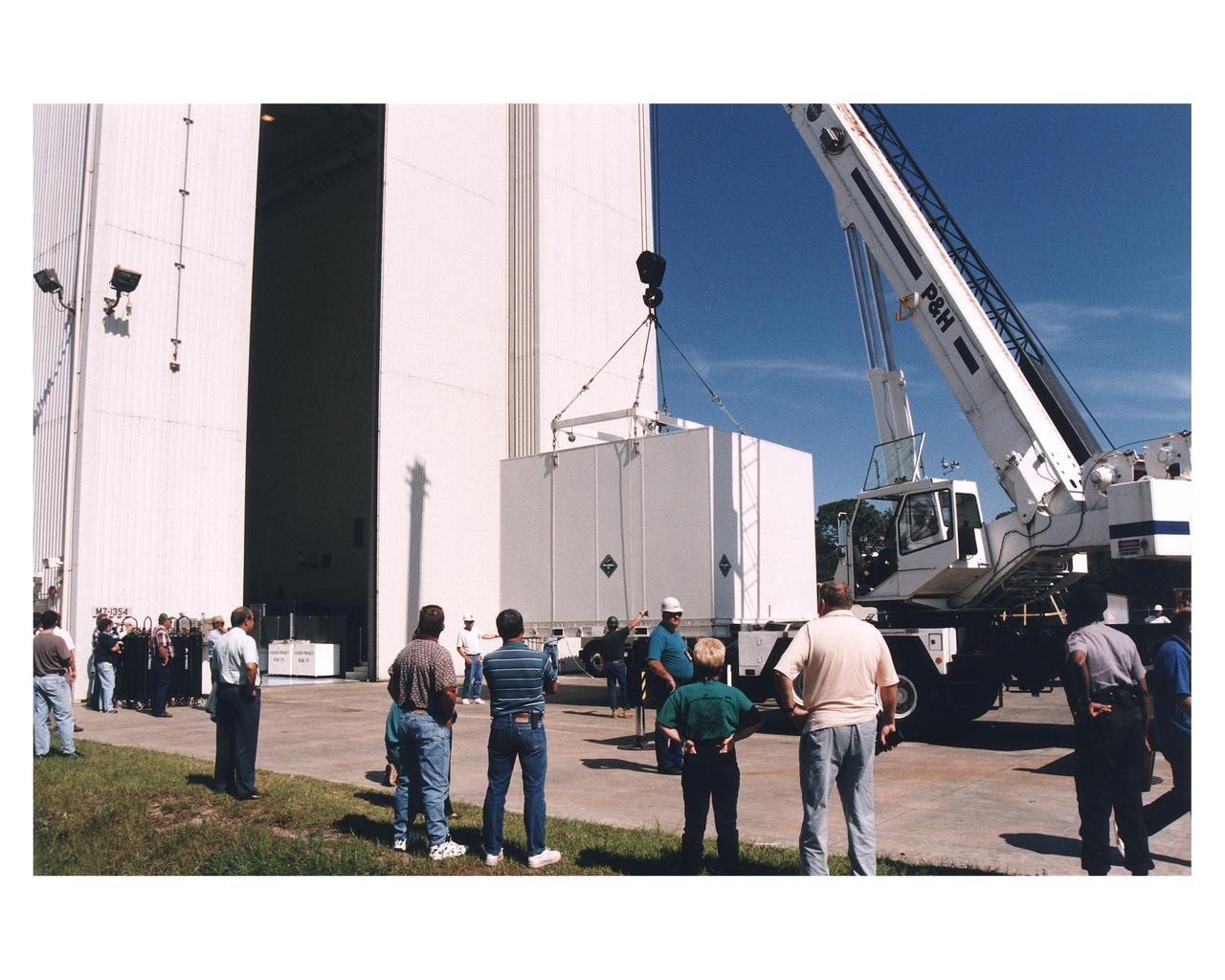
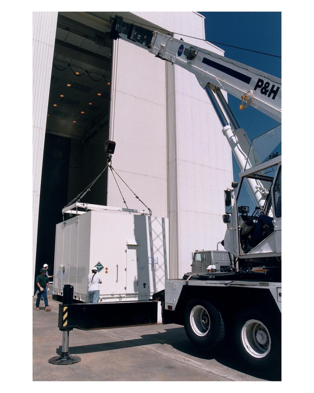
Workers prepare to move the shipping container with the Cassini orbiter inside the Payload Hazardous Servicing Facility (PHSF) for prelaunch processing, testing and integration. The <a href="http://www-pao.ksc.nasa.gov/kscpao/release/1997/66-97.htm">orbiter arrived</a> at KSC’s Shuttle Landing Facility in a U.S. Air Force C-17 air cargo plane from Edwards Air Force Base, California. The orbiter and the Huygens probe already being processed at KSC are the two primary components of the Cassini spacecraft, which will be launched on a Titan IVB/Centaur expendable launch vehicle from Cape Canaveral Air Station. Cassini will explore Saturn, its rings and moons for four years. The Huygens probe, designed and developed for the European Space Agency (ESA), will be deployed from the orbiter to study the clouds, atmosphere and surface of Saturn’s largest moon, Titan. The orbiter was designed and assembled at NASA’s Jet Propulsion Laboratory in California. Following postflight inspections, integration of the 12 science instruments not already installed on the orbiter will be completed. Then, the parabolic high-gain antenna and the propulsion module will be mated to the orbiter, followed by the Huygens probe, which will complete spacecraft integration. The Cassini mission is targeted for an Oct. 6 launch to begin its 6.7-year journey to the Saturnian system. Arrival at the planet is expected to occur around July 1, 2004
Workers prepare to move the shipping container with the Cassini orbiter inside the Payload Hazardous Servicing Facility (PHSF) for prelaunch processing, testing and integration. The <a href="http://www-pao.ksc.nasa.gov/kscpao/release/1997/66-97.htm">orbiter arrived</a> at KSC’s Shuttle Landing Facility in a U.S. Air Force C-17 air cargo plane from Edwards Air Force Base, California. The orbiter and the Huygens probe already being processed at KSC are the two primary components of the Cassini spacecraft, which will be launched on a Titan IVB/Centaur expendable launch vehicle from Cape Canaveral Air Station. Cassini will explore Saturn, its rings and moons for four years. The Huygens probe, designed and developed for the European Space Agency (ESA), will be deployed from the orbiter to study the clouds, atmosphere and surface of Saturn’s largest moon, Titan. The orbiter was designed and assembled at NASA’s Jet Propulsion Laboratory in California. Following postflight inspections, integration of the 12 science instruments not already installed on the orbiter will be completed. Then, the parabolic high-gain antenna and the propulsion module will be mated to the orbiter, followed by the Huygens probe, which will complete spacecraft integration. The Cassini mission is targeted for an Oct. 6 launch to begin its 6.7-year journey to the Saturnian system. Arrival at the planet is expected to occur around July 1, 2004
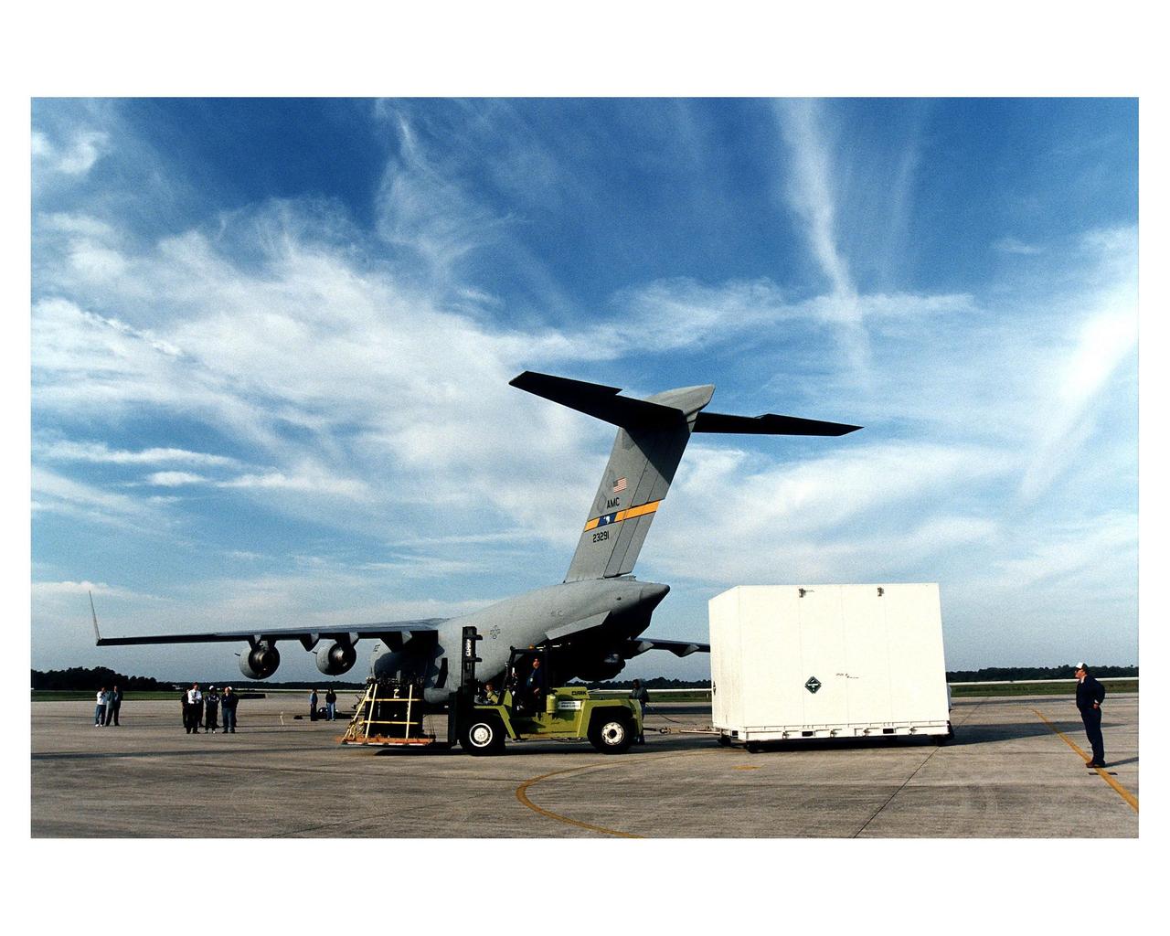
Workers prepare to tow away the large container with the Cassini orbiter from KSC’s Shuttle Landing Facility. The orbiter <a href="http://www-pao.ksc.nasa.gov/kscpao/release/1997/66-97.htm">just arrived</a> on the U.S. Air Force C-17 air cargo plane, shown here, from Edwards Air Force Base, California. The orbiter and the Huygens probe already being processed at KSC are the two primary components of the Cassini spacecraft, which will be launched on a Titan IVB/Centaur expendable launch vehicle from Cape Canaveral Air Station. Cassini will explore Saturn, its rings and moons for four years. The Huygens probe, designed and developed for the European Space Agency (ESA), will be deployed from the orbiter to study the clouds, atmosphere and surface of Saturn’s largest moon, Titan. The orbiter was designed and assembled at NASA’s Jet Propulsion Laboratory in California. Following postflight inspections, integration of the 12 science instruments not already installed on the orbiter will be completed. Then, the parabolic high-gain antenna and the propulsion module will be mated to the orbiter, followed by the Huygens probe, which will complete spacecraft integration. The Cassini mission is targeted for an Oct. 6 launch to begin its 6.7-year journey to the Saturnian system. Arrival at the planet is expected to occur around July 1, 2004
Workers prepare to move the shipping container with the Cassini orbiter inside the Payload Hazardous Servicing Facility (PHSF) for prelaunch processing, testing and integration. The <a href="http://www-pao.ksc.nasa.gov/kscpao/release/1997/66-97.htm">orbiter arrived</a> at KSC’s Shuttle Landing Facility in a U.S. Air Force C-17 air cargo plane from Edwards Air Force Base, California. The orbiter and the Huygens probe already being processed at KSC are the two primary components of the Cassini spacecraft, which will be launched on a Titan IVB/Centaur expendable launch vehicle from Cape Canaveral Air Station. Cassini will explore Saturn, its rings and moons for four years. The Huygens probe, designed and developed for the European Space Agency (ESA), will be deployed from the orbiter to study the clouds, atmosphere and surface of Saturn’s largest moon, Titan. The orbiter was designed and assembled at NASA’s Jet Propulsion Laboratory in California. Following postflight inspections, integration of the 12 science instruments not already installed on the orbiter will be completed. Then, the parabolic high-gain antenna and the propulsion module will be mated to the orbiter, followed by the Huygens probe, which will complete spacecraft integration. The Cassini mission is targeted for an Oct. 6 launch to begin its 6.7-year journey to the Saturnian system. Arrival at the planet is expected to occur around July 1, 2004
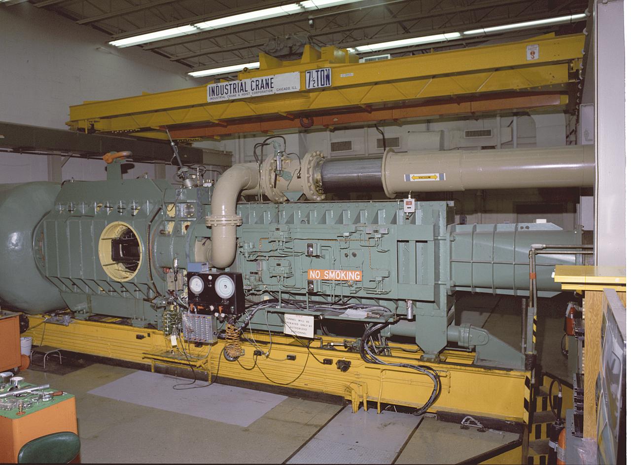
This photograph shows an overall view of the Marshall Space Flight Center's (MSFC's) 14x14-Inch Trisonic Wind Tunnel. The 14-Inch Wind Tunnel is a trisonic wind tunnel. This means it is capable of running subsonic, below the speed of sound; transonic, at or near the speed of sound (Mach 1, 760 miles per hour at sea level); or supersonic, greater than Mach 1 up to Mach 5. It is an intermittent blowdown tunnel that operates by high pressure air flowing from storage to either vacuum or atmospheric conditions. The MSFC 14x14-Inch Trisonic Wind Tunnel has been an integral part of the development of the United States space program Rocket and launch vehicles from the Jupiter-C in 1958, through the Saturn family up to the current Space Shuttle and beyond have been tested in this Wind Tunnel. MSFC's 14x14-Inch Trisonic Wind Tunnel, as with most other wind tunnels, is named after the size of the test section. The 14-Inch Wind Tunnel, as in the past, will continue to play a large but unseen role in the development of America's space program.
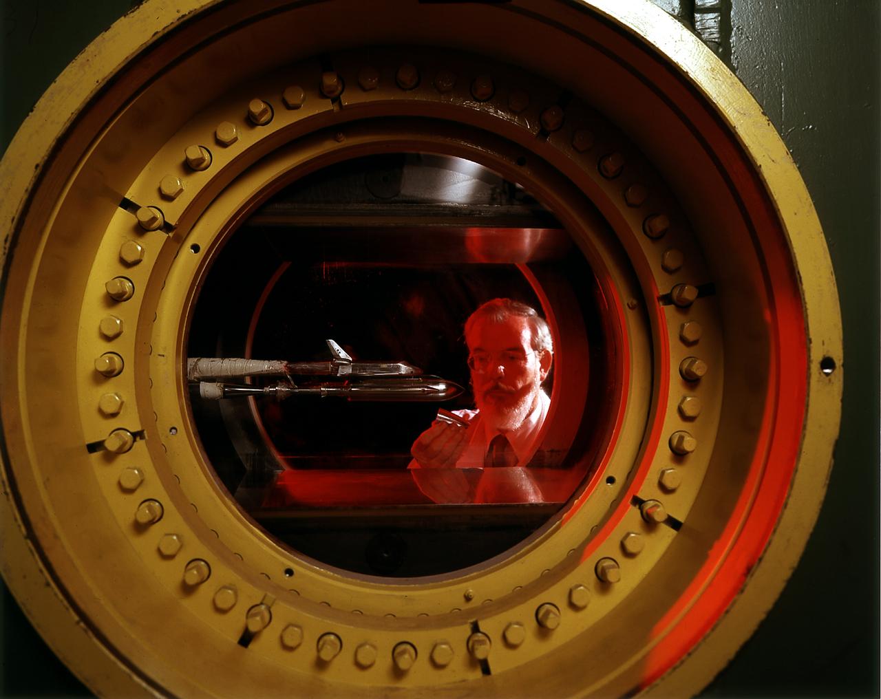
An engineer at the Marshall Space Flight Center (MSFC) observes a model of the Space Shuttle Orbiter being tested in the MSFC's 14x14-Inch Trisonic Wind Tunnel. The 14-Inch Wind Tunnel is a trisonic wind tunnel. This means it is capable of running subsonic, below the speed of sound; transonic, at or near the speed of sound (Mach 1,760 miles per hour at sea level); or supersonic, greater than Mach 1 up to Mach 5. It is an intermittent blowdown tunnel that operates by high pressure air flowing from storage to either vacuum or atmospheric conditions. The MSFC 14x14-Inch Trisonic Wind Tunnel has been an integral part of the development of the United States space program Rocket and launch vehicles from the Jupiter-C in 1958, through the Saturn family up to the current Space Shuttle and beyond have been tested in this Wind Tunnel. MSFC's 14x14-Inch Trisonic Wind Tunnel, as with most other wind tunnels, is named after the size of the test section. The 14-Inch Wind Tunnel, as in the past, will continue to play a large but unseen role in the development of America's space program.