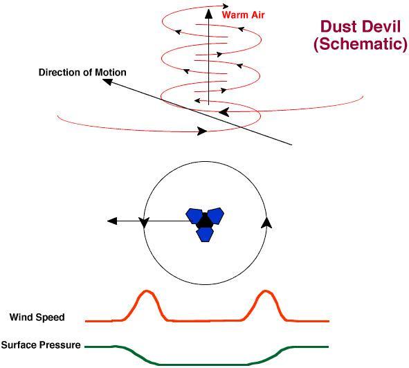
Dust Devil Schematic
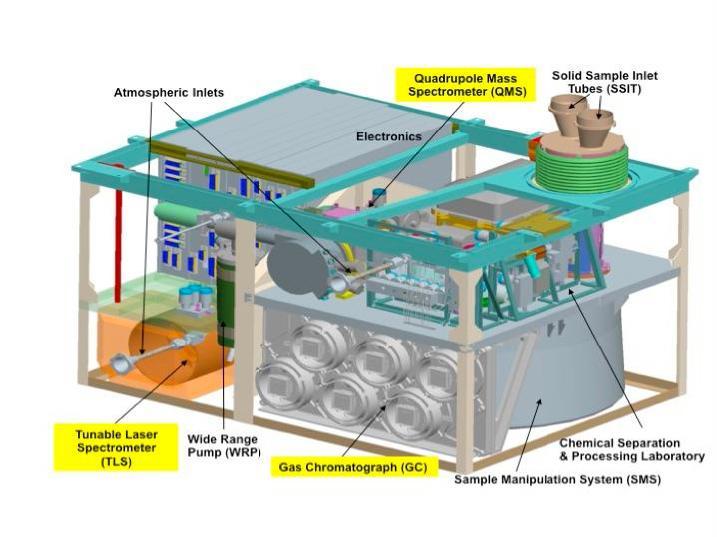
This schematic illustration for NASA Mars Science Laboratory Sample Analysis at Mars SAM instrument shows major components of the microwave-oven-size instrument, which will examine samples of Martian rocks, soil and atmosphere.
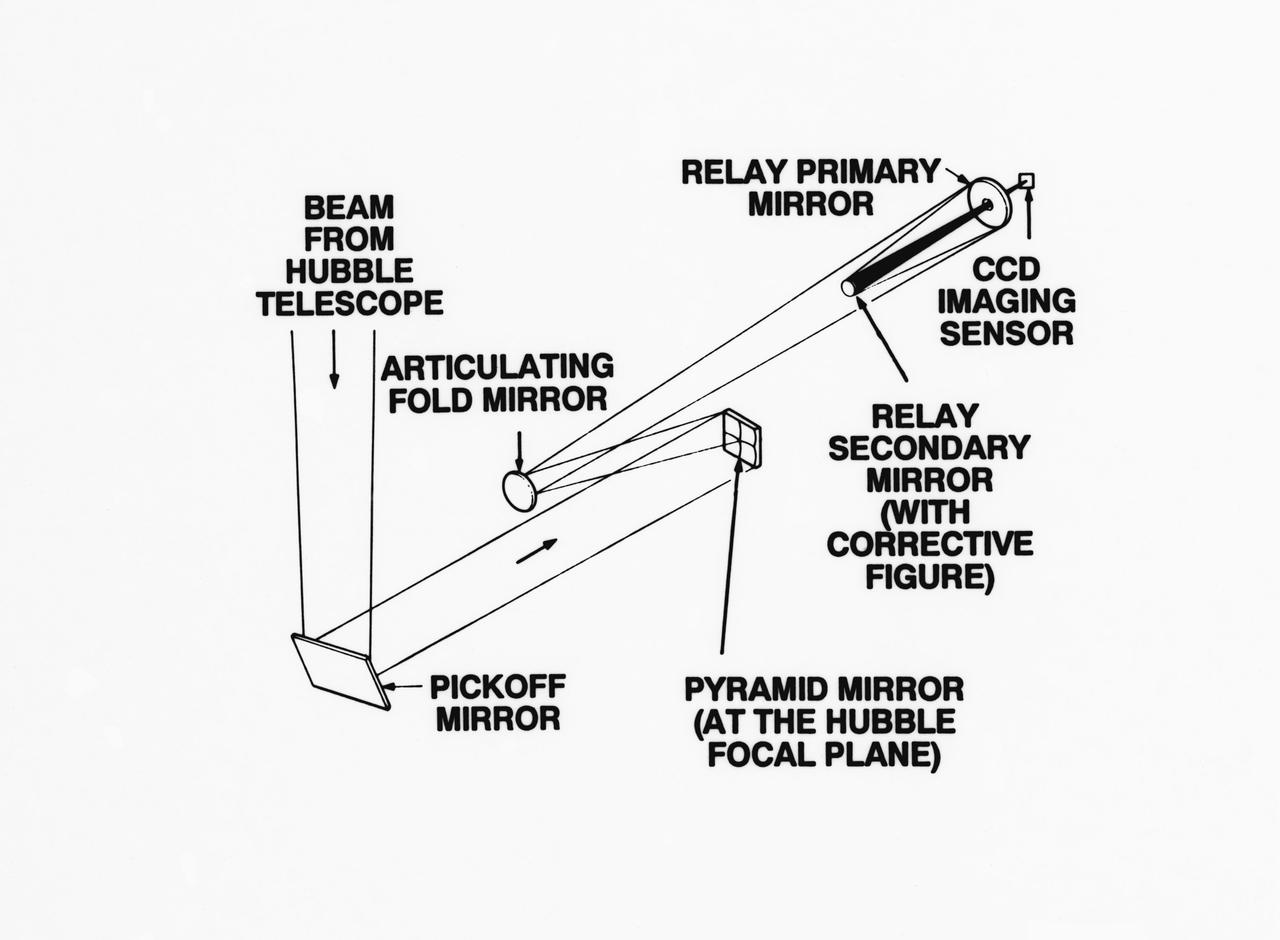
S93-33258 (15 Mar 1993) --- An optical schematic diagram of one of the four channels of the Wide Field\Planetary Camera-2 (WF\PC-2) shows the path taken by beams from the Hubble Space Telescope (HST) before an image is formed at the camera's charge-coupled devices. A team of NASA astronauts will pay a visit to the HST later this year, carrying with them the new WF/PC-2 to replace the one currently on the HST. The Jet Propulsion Laboratory in Pasadena, California has been working on the replacement system for several months. See NASA photo S93-33257 for a close-up view of tiny articulating mirrors designed to realign incoming light in order to make certain the beams fall precisely in the middle of the secondary mirrors.
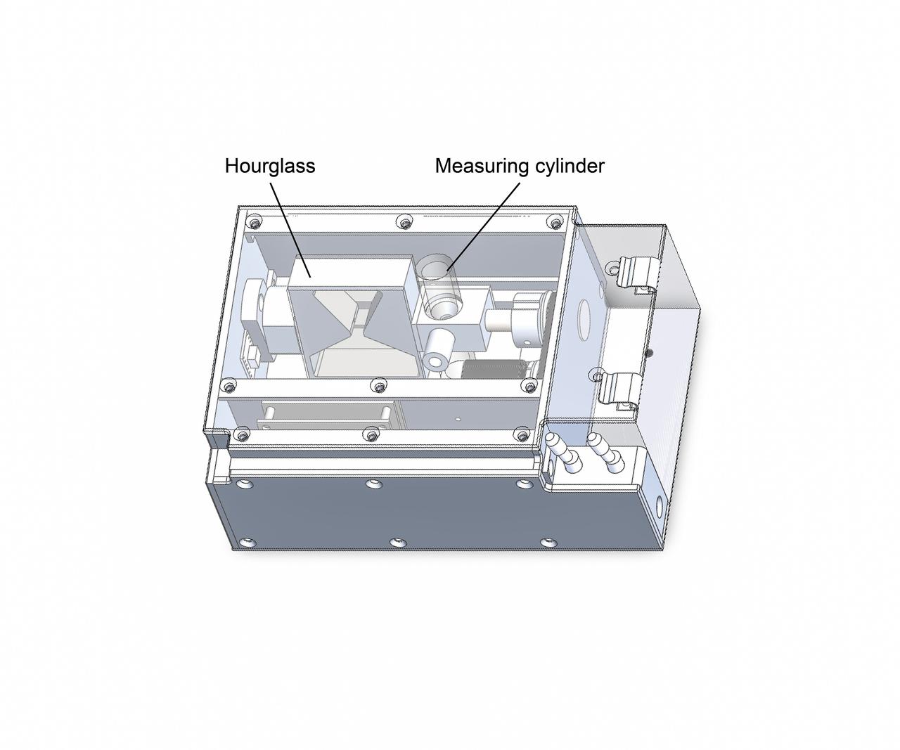
jsc2019e039831 (7/8/2019) --- A view of the Hourglass Apparatus schematic. The Hourglass investigation examines the relationship between gravity and the behavior of granular materials such as regolith that covers the surface of planets and planetary-like bodies. Researchers observe various granular materials inside an hourglass and a measuring cylinder under different gravity conditions. Better understanding of the behavior of these materials supports the design of spacecraft for future missions landing on the surfaces of planets and other celestial bodies. (Image courtesy of: JAXA)
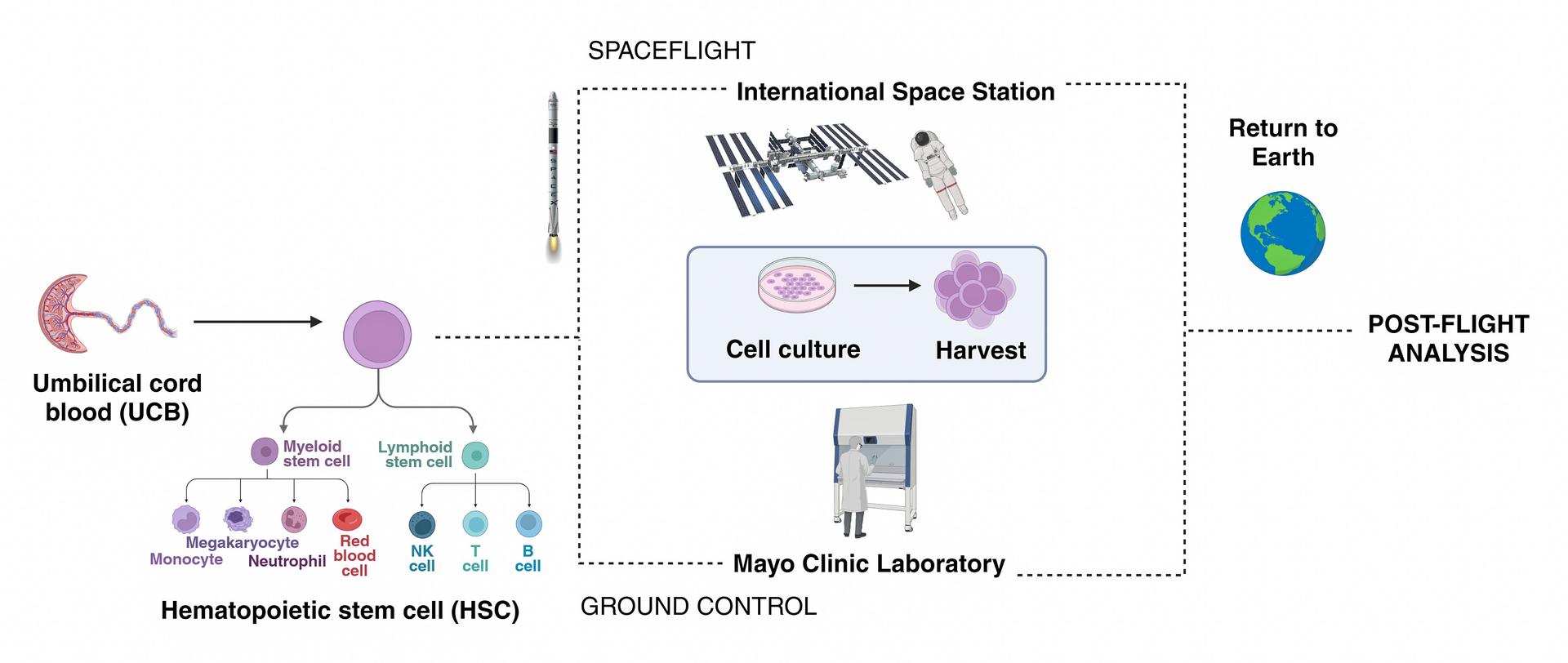
jsc2026e014321 (March 23, 2026) --- Simple schematic diagram of the InSPA-StemCellEX-H2 investigation design, which works upon prior research to produce stem cells in greater numbers in space with BioServe’s newly developed microgravity bioreactor. Credit: Mayo Clinic.

This schematic details the third High Energy Astronomy Observatory (HEAO)-3. The HEAO-3's mission was to survey and map the celestial sphere for gamma-ray flux and make detailed measurements of cosmic-ray particles. It carried three scientific experiments: a gamma-ray spectrometer, a cosmic-ray isotope experiment, and a heavy cosmic-ray nuclei experiment. The HEAO-3 was originally identified as HEAO-C but the designation was changed once the spacecraft achieved orbit.
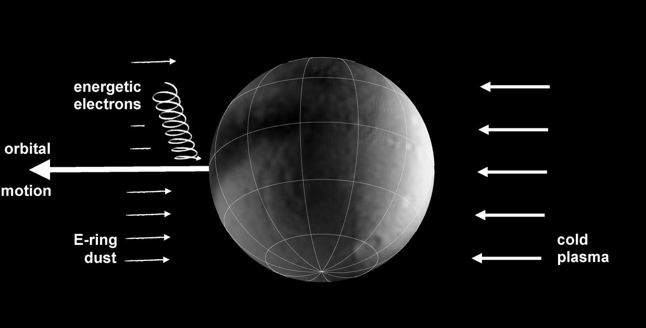
This schematic graphic illustrates the bombardments that lead to colorful splotches and bands on the surfaces of several icy moons of Saturn.
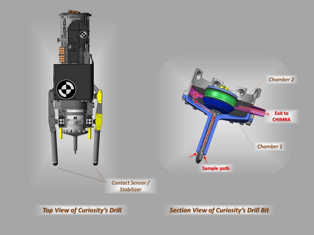
These schematic drawings show a top view and a cutaway view of a section of the drill on NASA Curiosity rover on Mars.
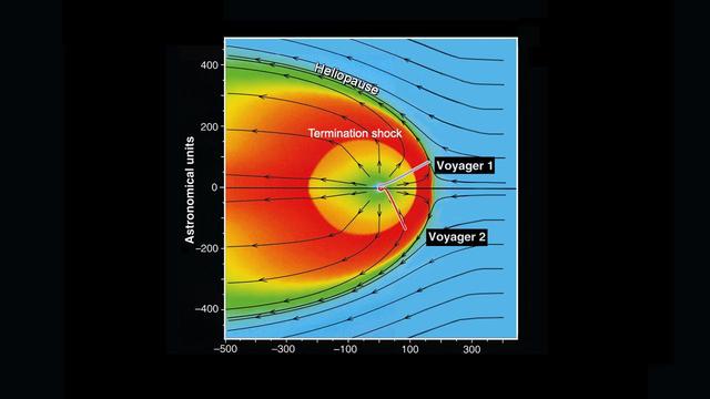
This schematic shows our solar bubble moving through nearby interstellar space, or the space between stars.
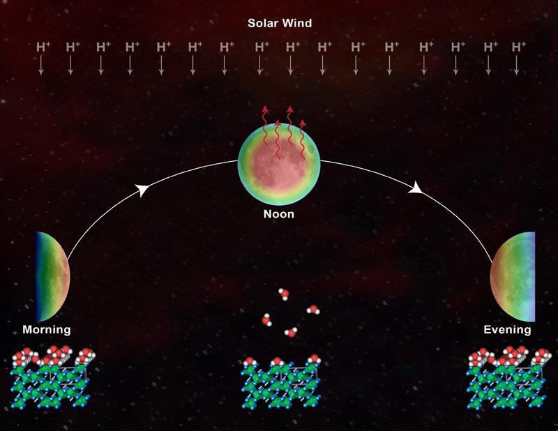
A schematic shows the daytime cycle of hydration, loss and rehydration on the lunar surface. This theory is based on data from NASA Deep Impact mission.

This illustration schematically shows where the Shallow Radar instrument on NASA Mars Reconnaissance Orbiter detected flood channels that had been buried by lava flows in the Elysium Planitia region of Mars.
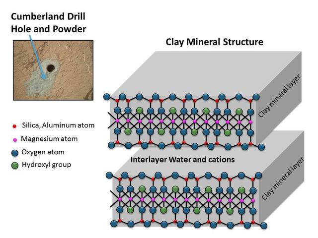
This schematic shows the atomic structure of the smallest units that make up the layers and interlayer region of clay minerals. This structure is similar to the clay mineral in drilled rock powder collected by NASA Curiosity Mars rover.
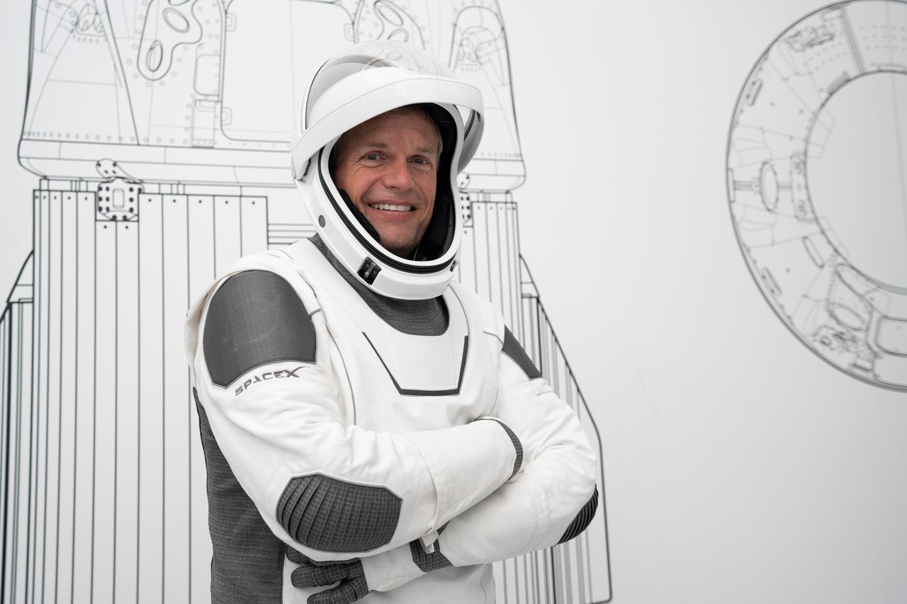
SpaceX USCV-7 (Crew 7) Schematic Photos Imagery provided by SpaceX.
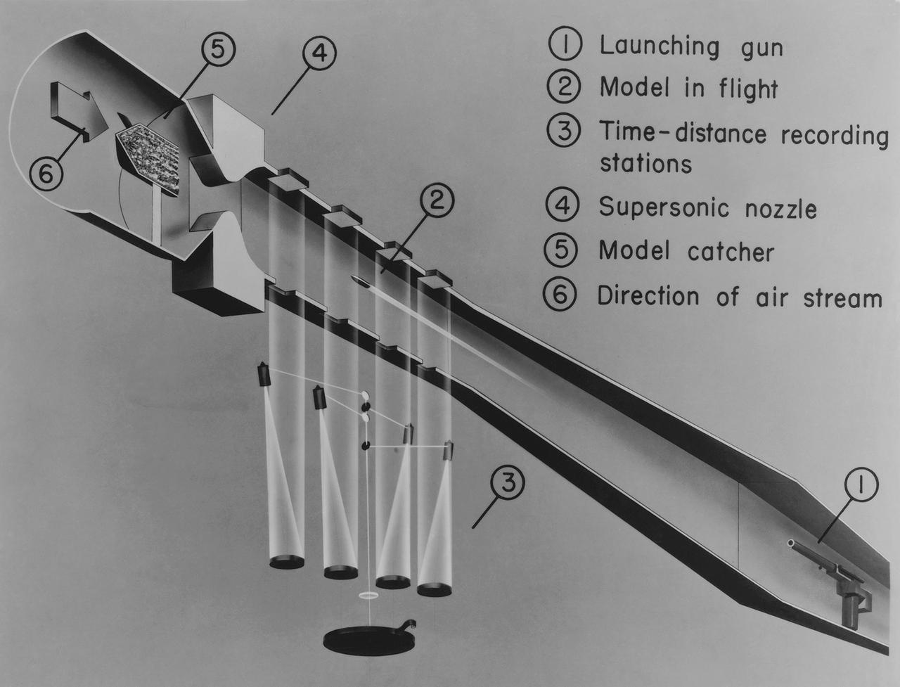
Ames hi-speed research schematic drawing of the Supersonic Free Flight Tunnel (SSFFT)
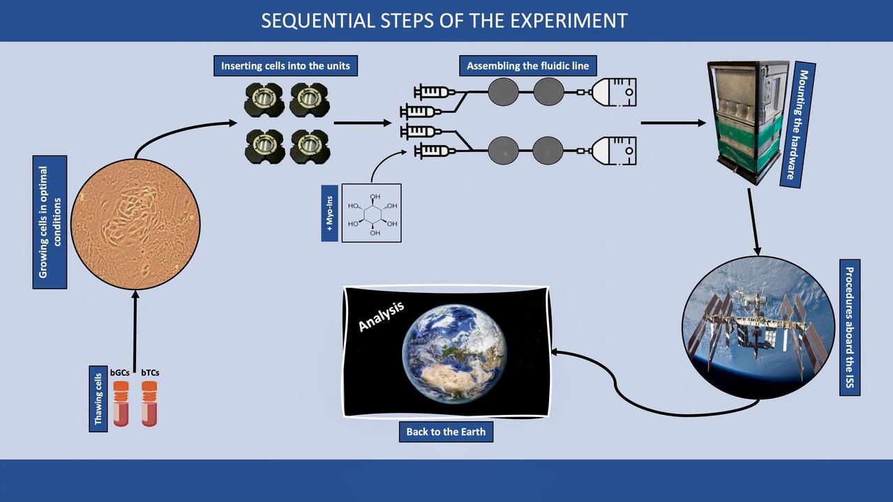
jsc2024e071690 (11/5/2024) --- Schematic representation of the sequential steps of the Ovarian Research In microgravity cONditions-2 (ORION-2) investigation. Image courtesy of Italian Space Agency (ASI).
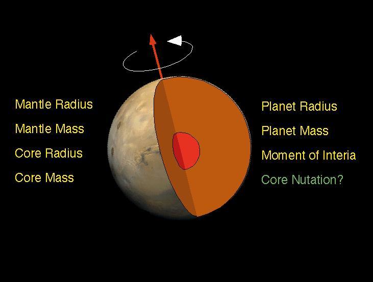
The interior of Mars is simply modeled as a core and mantle with a thin crust, similar to Earth. Mars' size and total mass have been determined by previous missions. Given four parameters, the core size and mass, and mantle size and mass can be determined. The combination of Pathfinder Doppler data with earlier data from the Viking landers has determined a third parameter, the moment of inertia, through measurement of Mars' precession rate. A fourth measurement is needed to complete the interior model. This may be achieved through future Doppler tracking of Pathfinder, since the presence of a fluid core may be detectable through its effect on Mars' nutation. The determination of the moment of inertia is a significant constraint on possible models for Mars' interior. If the core is as dense as possible (i.e. completely iron) and the mantle is similar to Earth's (or similar to the SNC meteorites thought to originate on Mars) then the minimum core radius is about 1300 km. If the core is made of less-dense material (i.e. a mixture of iron and sulfur) then the core radius is probably no more than 2000 km. Sojourner spent 83 days of a planned seven-day mission exploring the Martian terrain, acquiring images, and taking chemical, atmospheric and other measurements. The final data transmission received from Pathfinder was at 10:23 UTC on September 27, 1997. Although mission managers tried to restore full communications during the following five months, the successful mission was terminated on March 10, 1998. http://photojournal.jpl.nasa.gov/catalog/PIA00974

This illustration shows the unusual orbit of planet Kepler-413b around a close pair of orange and red dwarf stars. The planet 66-day orbit is tilted 2.5 degrees with respect to the plane of the binary stars orbit.
This image shows the workings of the microscope station of the Microscopy, Electrochemistry and Conductivity Analyzer MECA instrument suite of NASA Phoenix Mars Lander.
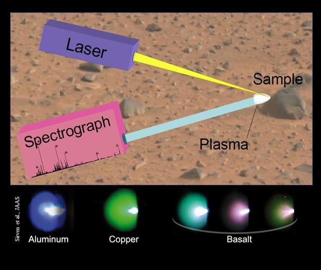
This image illustrates the principals of a technique called laser-induced breakdown spectroscopy, which the Chemistry and Camera ChemCam instrument onboard NASA rover, Curiosity, will use on Mars.
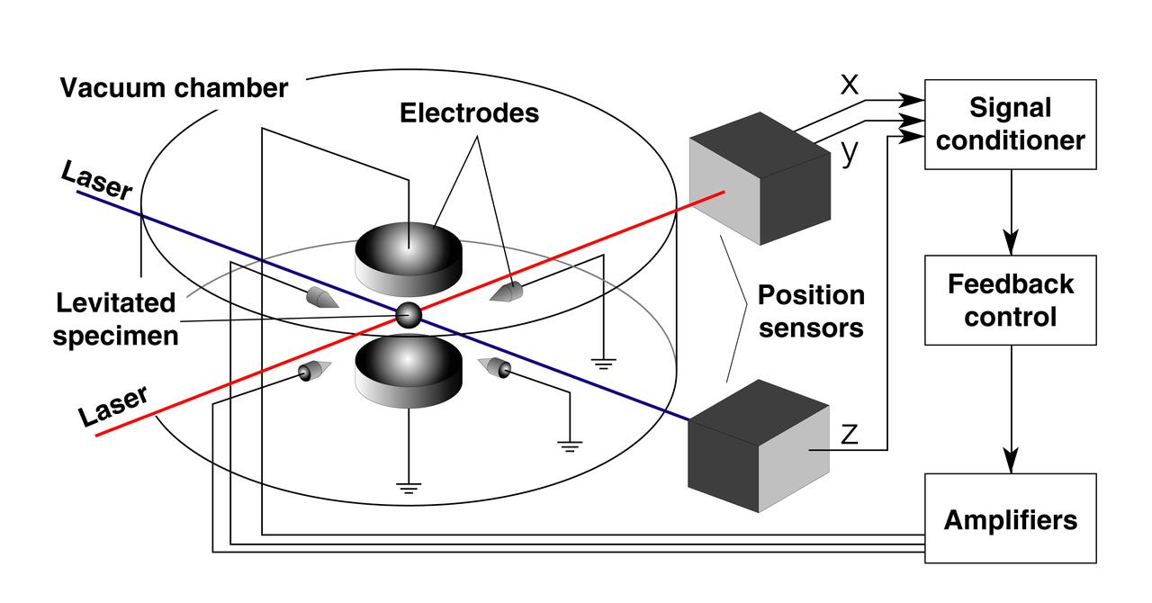
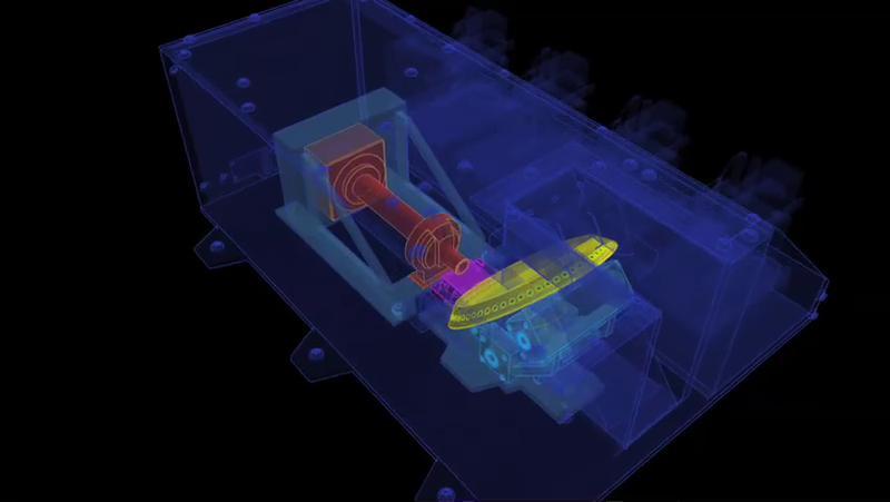
Schematic of Electrostatic Levitator (ESL) electrodes and controls system. The ESL uses static electricity to suspend an object (about 2-3 mm in diameter) inside a vacuum chamber while a laser heats the sample until it melts. This lets scientists record a wide range of physical properties without the sample contacting the container or any instruments, conditions that would alter the readings. The Electrostatic Levitator is one of several tools used in NASA's microgravity materials science program.

KENNEDY SPACE CENTER, FLA. - Inside the SPACEHAB module at SPACEHAB, Cape Canaveral, Fla., Pilot William 'Willie' McCool (kneeling) and Mission Specialist David Brown (standing, right) look over schematics. STS-107 is a research mission, and the primary payload is the first flight of the SHI Research Double Module (SHI_RDM). The experiments range from material sciences to life sciences (many rats). Among the experiments is a Hitchhiker carrier system, modular and expandable in accordance with payload requirements. STS-107 is scheduled to launch in June 2002
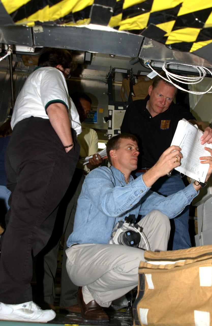
KENNEDY SPACE CENTER, FLA. - Inside the SPACEHAB module at SPACEHAB, Cape Canaveral, Fla., Pilot William "Willie" McCool (kneeling) and Mission Specialist David Brown (standing, right) look over schematics. STS-107 is a research mission, and the primary payload is the first flight of the SHI Research Double Module (SHI/RDM). The experiments range from material sciences to life sciences (many rats). Among the experiments is a Hitchhiker carrier system, modular and expandable in accordance with payload requirements. STS-107 is scheduled to launch in June 2002
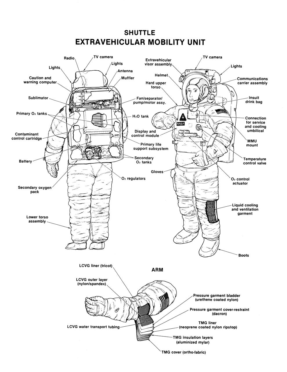
Labeled cutaway line drawing of the Shuttle extravehicular mobility unit (EMU) identifies its various components and equipment. The portable life support system (PLSS) and protective layers of fabric (thermal micrometeoroid garment (TMG)) incorporated in this extravehicular activity (EVA) space suit are shown.
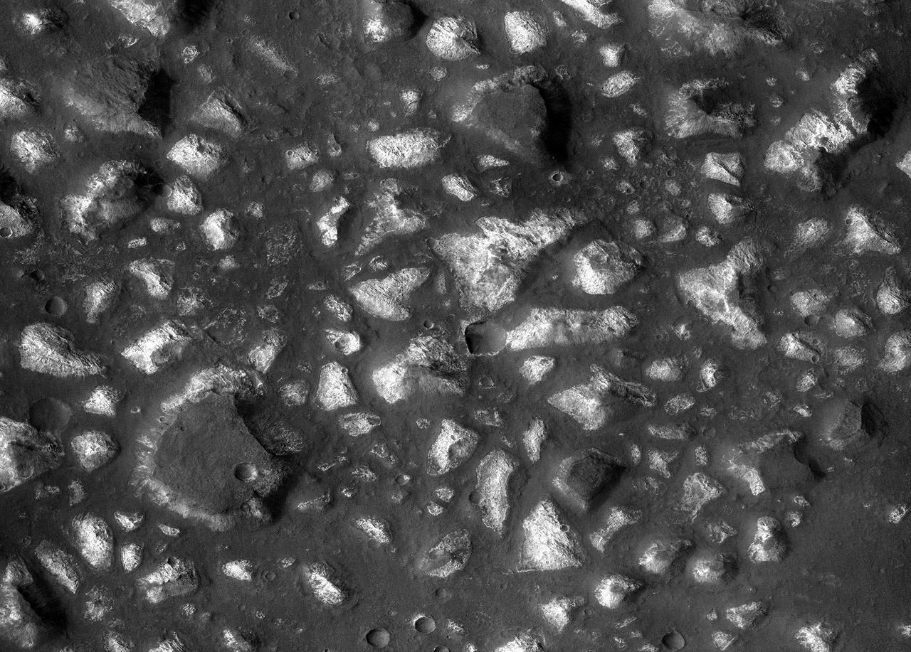
This view of a portion of the Eridania region of southern Mars shows fractured, dismembered blocks of deep-basin deposits that have been surrounded and partially buried by younger volcanic deposits. The image was taken by the Context Camera on NASA's Mars Reconnaissance Orbiter. The area covered by this view spans about 12 miles (20 kilometers) across. The shape and texture of the thick bedrock layers in the Eridania basin, together with the mix of minerals identified from orbit, led researchers to identify this as the site of possible seafloor hydrothermal deposits. A schematic cross section (PIA22059 of this terrain shows an interpretation of its origin. The mineral identifications were made from observations by the Mars Reconnaissance Orbiter's Compact Reconnaissance Imaging Spectrometer for Mars. This is a portion of Context Camera image B08_012563_1445. https://photojournal.jpl.nasa.gov/catalog/PIA22058
S93-33257 (15 Mar 1993) --- This close-up view features tiny articulating fold mirrors that will go into a replacement camera for the Wide Field\Planetary Camera (WF\PC-1) currently on the Hubble Space Telescope (HST). A team of NASA astronauts will pay a visit to the HST later this year, carrying with them the new WF/PC-2 to replace the one currently on the HST. The Jet Propulsion Laboratory (JPL) in Pasadena, California has been working on the replacement system for several months. See NASA photo S93-33258 for an optical schematic diagram of one of the four channels of the WF\PC-2 showing the path taken by beams from the HST before an image is formed at the camera's charge-coupled devices.
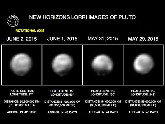
These images, taken by NASA's New Horizons' Long Range Reconnaissance Imager (LORRI), show four different "faces" of Pluto as it rotates about its axis with a period of 6.4 days. All the images have been rotated to align Pluto's rotational axis with the vertical direction (up-down) on the figure, as depicted schematically in the upper left. From left to right, the images were taken when Pluto's central longitude was 17, 63, 130, and 243 degrees, respectively. The date of each image, the distance of the New Horizons spacecraft from Pluto, and the number of days until Pluto closest approach are all indicated in the figure.These images show dramatic variations in Pluto's surface features as it rotates. When a very large, dark region near Pluto's equator appears near the limb, it gives Pluto a distinctly, but false, non-spherical appearance. Pluto is known to be almost perfectly spherical from previous data. These images are displayed at four times the native LORRI image size, and have been processed using a method called deconvolution, which sharpens the original images to enhance features on Pluto. Deconvolution can occasionally introduce "false" details, so the finest details in these pictures will need to be confirmed by images taken from closer range in the next few weeks. All of the images are displayed using the same brightness scale. http://photojournal.jpl.nasa.gov/catalog/PIA19686
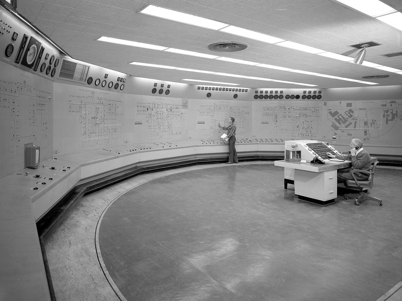
Operators in the Engine Research Building’s Central Control Room at the National Aeronautics and Space Administration (NASA) Lewis Research Center. The massive 4.25-acre Engine Research Building contains dozens of test cells, test stands, and altitude chambers. A powerful a collection of compressors and exhausters located in the central portion of the basement provides process air and exhaust for these test areas. This system is connected to similar process air systems in the laboratory’s other large test facilities. The Central Control Room coordinates this activity and communicates with the local utilities. The panels on the wall contain schematics with indicator lights and instrumentation for the atmospheric exhaust, altitude exhaust, refrigerated air, and process air systems. The process air equipment included twelve exhausters, four compressors, refrigeration system, cooling water, and an exhaust system. The operators in the control room kept in contact with engineers running the process air system and those conducting the tests in the test cells. The operators also coordinated with the local power companies to make sure enough electricity was available to operate the powerful compressors and exhausters.
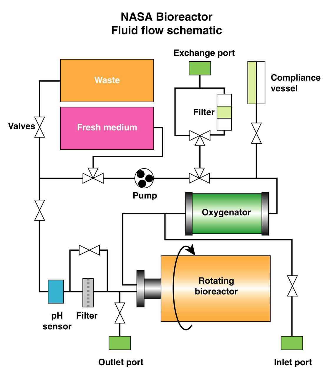
The schematic depicts the major elements and flow patterns inside the NASA Bioreactor system. Waste and fresh medium are contained in plastic bags placed side-by-side so the waste bag fills as the fresh medium bag is depleted. The compliance vessel contains a bladder to accommodate pressure transients that might damage the system. A peristolic pump moves fluid by squeezing the plastic tubing, thus avoiding potential contamination. The work is sponsored by NASA's Office of Biological and Physical Research. The bioreactor is managed by the Biotechnology Cell Science Program at NASA's Johnson Space Center (JSC). NASA-sponsored bioreactor research has been instrumental in helping scientists to better understand normal and cancerous tissue development. In cooperation with the medical community, the bioreactor design is being used to prepare better models of human colon, prostate, breast and ovarian tumors. Cartilage, bone marrow, heart muscle, skeletal muscle, pancreatic islet cells, liver and kidney are just a few of the normal tissues being cultured in rotating bioreactors by investigators.
S82-31408 (May 1983) --- The Spacelab 2 emblem is a symbolic representation of the scientific objectives of the mission. The emblem is in the shape of a triangular shield with convexly curved edges. Across the top of a black out border are the words ?SPACELAB 2?. Within the black border is a sky blue border carryhing the words: ?ASTRONOMY?, ON TOP? ?PHYSICS?, on the left; and ?BIOLOGY?, on the right. Within the blue border is a schematic view of the sun, the earth, and the orbiter with Spacelab 2. The sun appears in the upper right background as a white disc surrounded by six concentric rings ranging grom bright yellow near the disc through yellow-red to a dark red out ring. A sector of the earth with blue ocean and a black portion of North America is in the upper left corner. The black and white Orbiter is seen from directly overhead in the foreground, the right side illuminated by the sun, the left side in shadow. Although the payload bay doors are not open, the Spacelab 2 payload is seen as if the doors were open. In black on white are seen the three pallets, and the separately mounted cosmic ray experiment at the aft end of the bay.
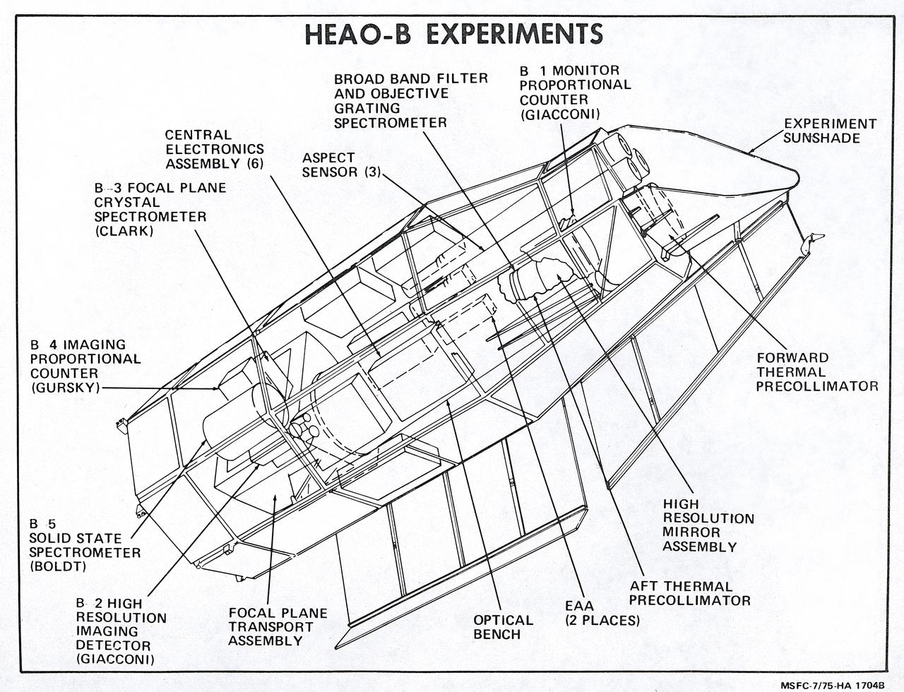
This illustration is a schematic of the High Energy Astronomy Observatory (HEAO)-2 and its experiments. It shows the focal plane instruments (at the right) plus the associated electronics for operating the telescope as it transmitted its observations to the ground. A fifth instrument, the Monitor Proportional Counter, is located near the front of the telescope. Four separate astronomical instruments are located at the focus of this telescope and they could be interchanged for different types of observations as the observatory pointed at interesting areas of the Sky. Two of these instruments produced images; a High Resolution Imaging Detector and an Imaging Proportional Counter. The other two instruments, the Solid State Spectrometer and the Crystal Spectrometer, measured the spectra of x-ray objects. A fifth instrument, the Monitor Proportional Counter, continuously viewed space independently to study a wider band of x-ray wavelengths and to examine the rapid time variations in the sources. The HEAO-2 was nicknamed the Einstein Observatory by its scientific experimenters in honor of the centernial of the birth of Albert Einstein, whose concepts of relativity and gravitation have influenced much of modern astrophysics, particularly x-ray astronomy. The HEAO-2, designed and developed by TRW, Inc. under the project management of the Marshall Space Flight Center, was launched aboard an Atlas/Centaur launch vehicle on November 13, 1978. The HEAO-2 was originally identified as HEAO-B but the designation was changed once the spacecraft achieved orbit.
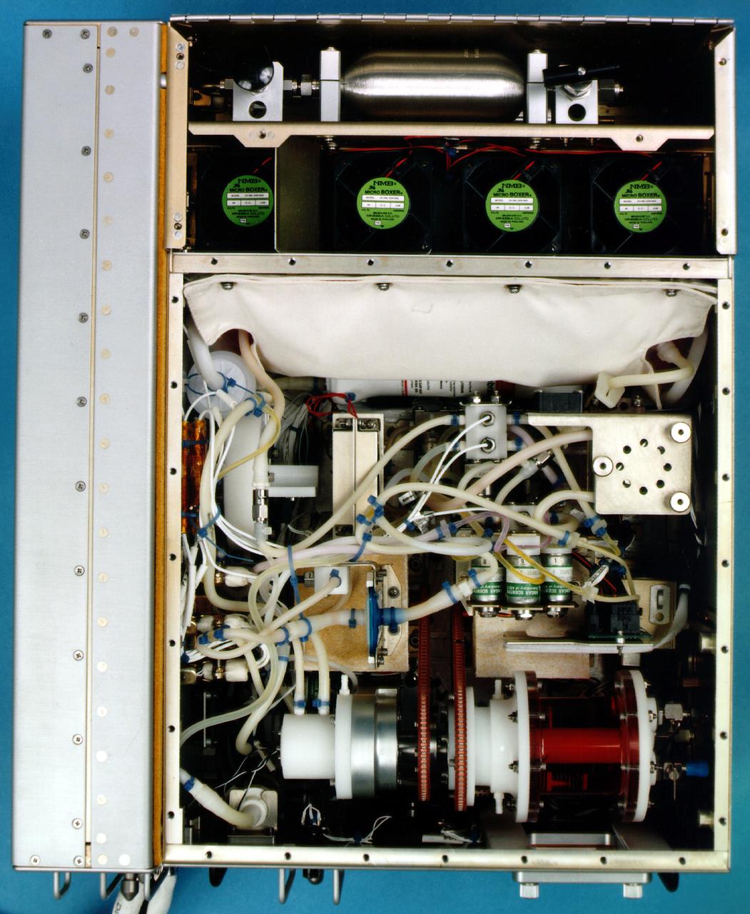
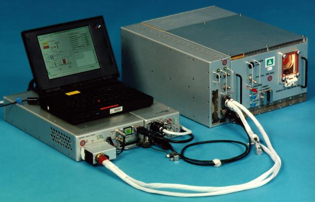
Bioreactor Demonstration System (BDS) comprises an electronics module, a gas supply module, and the incubator module housing the rotating wall vessel and its support systems. Nutrient media are pumped through an oxygenator and the culture vessel. The shell rotates at 0.5 rpm while the irner filter typically rotates at 11.5 rpm to produce a gentle flow that ensures removal of waste products as fresh media are infused. Periodically, some spent media are pumped into a waste bag and replaced by fresh media. When the waste bag is filled, an astronaut drains the waste bag and refills the supply bag through ports on the face of the incubator. Pinch valves and a perfusion pump ensure that no media are exposed to moving parts. An Experiment Control Computer controls the Bioreactor, records conditions, and alerts the crew when problems occur. The crew operates the system through a laptop computer displaying graphics designed for easy crew training and operation. The work is sponsored by NASA's Office of Biological and Physical Research. The bioreactor is managed by the Biotechnology Cell Science Program at NASA's Johnson Space Center (JSC). NASA-sponsored bioreactor research has been instrumental in helping scientists to better understand normal and cancerous tissue development. In cooperation with the medical community, the bioreactor design is being used to prepare better models of human colon, prostate, breast and ovarian tumors. Cartilage, bone marrow, heart muscle, skeletal muscle, pancreatic islet cells, liver and kidney are just a few of the normal tissues being cultured in rotating bioreactors by investigators. See No. 0101825 for a version with major elements labeled, and No. 0103180 for an operational schematic. 0101816
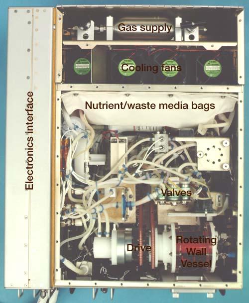
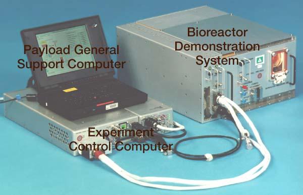
Bioreactor Demonstration System (BDS) comprises an electronics module, a gas supply module, and the incubator module housing the rotating wall vessel and its support systems. Nutrient media are pumped through an oxygenator and the culture vessel. The shell rotates at 0.5 rpm while the irner filter typically rotates at 11.5 rpm to produce a gentle flow that ensures removal of waste products as fresh media are infused. Periodically, some spent media are pumped into a waste bag and replaced by fresh media. When the waste bag is filled, an astronaut drains the waste bag and refills the supply bag through ports on the face of the incubator. Pinch valves and a perfusion pump ensure that no media are exposed to moving parts. An Experiment Control Computer controls the Bioreactor, records conditions, and alerts the crew when problems occur. The crew operates the system through a laptop computer displaying graphics designed for easy crew training and operation. The work is sponsored by NASA's Office of Biological and Physical Research. The bioreactor is managed by the Biotechnology Cell Science Program at NASA's Johnson Space Center (JSC). NASA-sponsored bioreactor research has been instrumental in helping scientists to better understand normal and cancerous tissue development. In cooperation with the medical community, the bioreactor design is being used to prepare better models of human colon, prostate, breast and ovarian tumors. Cartilage, bone marrow, heart muscle, skeletal muscle, pancreatic islet cells, liver and kidney are just a few of the normal tissues being cultured in rotating bioreactors by investigators. See No. 0101816 for a version without labels, and No. 0103180 for an operational schematic.
Bioreactor Demonstration System (BDS) comprises an electronics module, a gas supply module, and the incubator module housing the rotating wall vessel and its support systems. Nutrient media are pumped through an oxygenator and the culture vessel. The shell rotates at 0.5 rpm while the irner filter typically rotates at 11.5 rpm to produce a gentle flow that ensures removal of waste products as fresh media are infused. Periodically, some spent media are pumped into a waste bag and replaced by fresh media. When the waste bag is filled, an astronaut drains the waste bag and refills the supply bag through ports on the face of the incubator. Pinch valves and a perfusion pump ensure that no media are exposed to moving parts. An Experiment Control Computer controls the Bioreactor, records conditions, and alerts the crew when problems occur. The crew operates the system through a laptop computer displaying graphics designed for easy crew training and operation. The work is sponsored by NASA's Office of Biological and Physical Research. The bioreactor is managed by the Biotechnology Cell Science Program at NASA's Johnson Space Center (JSC). NASA-sponsored bioreactor research has been instrumental in helping scientists to better understand normal and cancerous tissue development. In cooperation with the medical community, the bioreactor design is being used to prepare better models of human colon, prostate, breast and ovarian tumors. Cartilage, bone marrow, heart muscle, skeletal muscle, pancreatic islet cells, liver and kidney are just a few of the normal tissues being cultured in rotating bioreactors by investigators. See No. 0101824 for a version with labels, and No. 0103180 for an operational schematic.
Bioreactor Demonstration System (BDS) comprises an electronics module, a gas supply module, and the incubator module housing the rotating wall vessel and its support systems. Nutrient media are pumped through an oxygenator and the culture vessel. The shell rotates at 0.5 rpm while the irner filter typically rotates at 11.5 rpm to produce a gentle flow that ensures removal of waste products as fresh media are infused. Periodically, some spent media are pumped into a waste bag and replaced by fresh media. When the waste bag is filled, an astronaut drains the waste bag and refills the supply bag through ports on the face of the incubator. Pinch valves and a perfusion pump ensure that no media are exposed to moving parts. An Experiment Control Computer controls the Bioreactor, records conditions, and alerts the crew when problems occur. The crew operates the system through a laptop computer displaying graphics designed for easy crew training and operation. The work is sponsored by NASA's Office of Biological and Physical Research. The bioreactor is managed by the Biotechnology Cell Science Program at NASA's Johnson Space Center (JSC). NASA-sponsored bioreactor research has been instrumental in helping scientists to better understand normal and cancerous tissue development. In cooperation with the medical community, the bioreactor design is being used to prepare better models of human colon, prostate, breast and ovarian tumors. Cartilage, bone marrow, heart muscle, skeletal muscle, pancreatic islet cells, liver and kidney are just a few of the normal tissues being cultured in rotating bioreactors by investigators. See No. 0101823 for a version without labels, and No. 0103180 for an operational schematic.