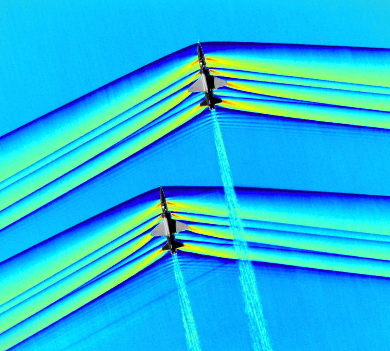
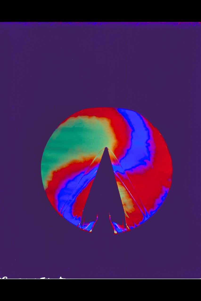
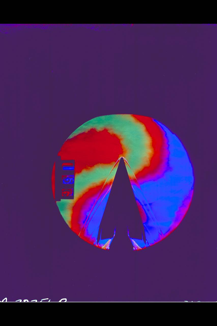
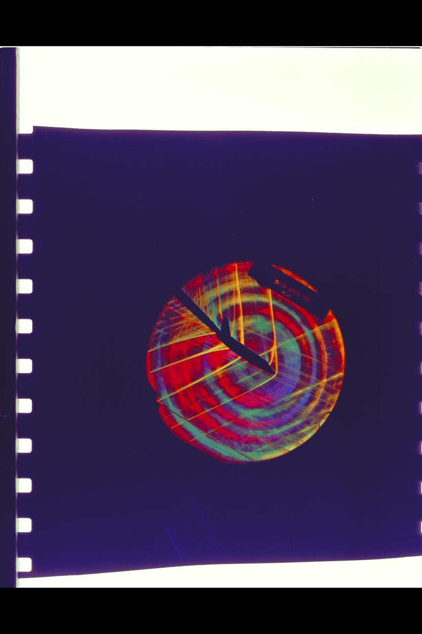
Composite image of Background Oriented Schlieren (BOS) data (contour) with a cut-out images of the T-38’s during a Mach Number 1.01 pass. This data is the first time shockwave interactions between two full scale aircraft traveling faster than the speed of sound have been imaged and shown with schlieren visualization. Original recording of the pass taken in the Black Mountain Supersonic Corridor at near Edwards AFB in December of 2018. Image acquired by JT Heineck, schlieren data processed by Neal Smith
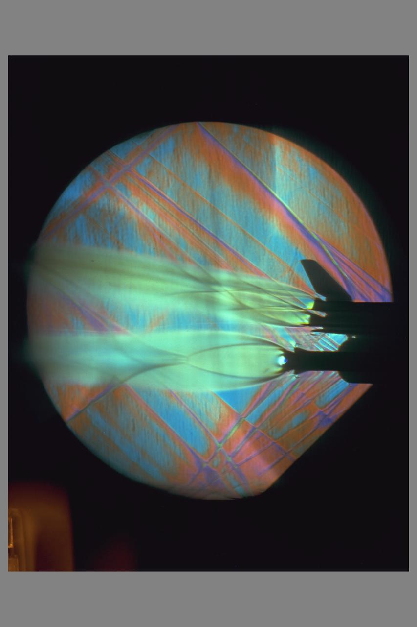
Composite image of Background Oriented Schlieren (BOS) data (contour) with a cut-out images of the T-38’s during a Mach Number 1.01 pass. This data is the first time shockwave interactions between two full scale aircraft traveling faster than the speed of sound have been imaged and shown with schlieren visualization. Original recording of the pass taken in the Black Mountain Supersonic Corridor at near Edwards AFB in December of 2018. Image acquired by JT Heineck, schlieren data processed by Neal Smith.

Composite image of Background Oriented Schlieren (BOS) data (contour) with a cut-out images of the T-38’s during a Mach Number 1.01 pass. This data is the first time shockwave interactions between two full scale aircraft traveling faster than the speed of sound have been imaged and shown with schlieren visualization. Original recording of the pass taken in the Black Mountain Supersonic Corridor at near Edwards AFB in December of 2018. Image acquired by JT Heineck, schlieren data processed by Neal Smith
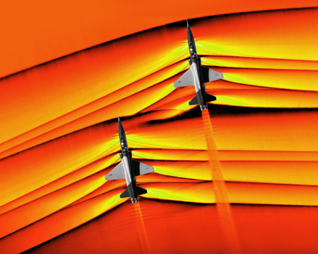
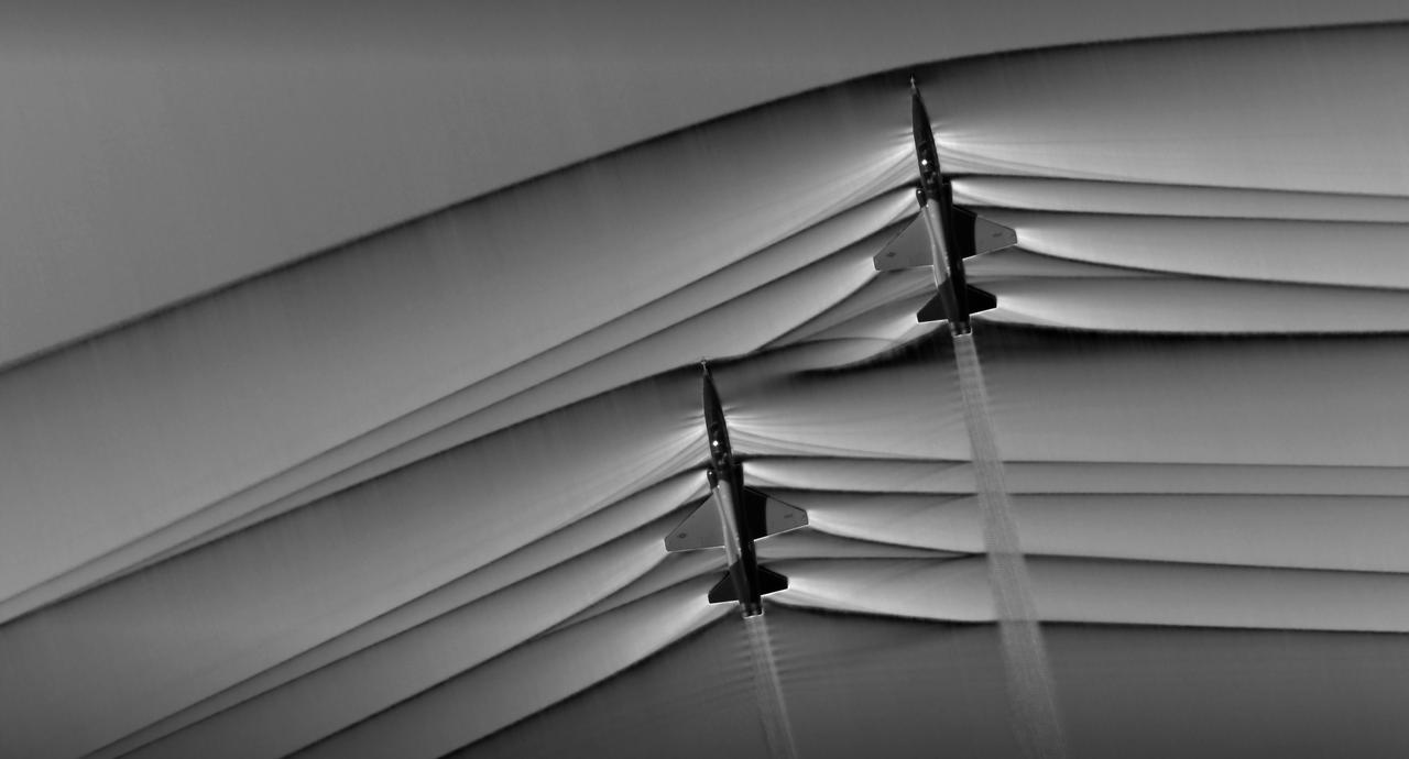
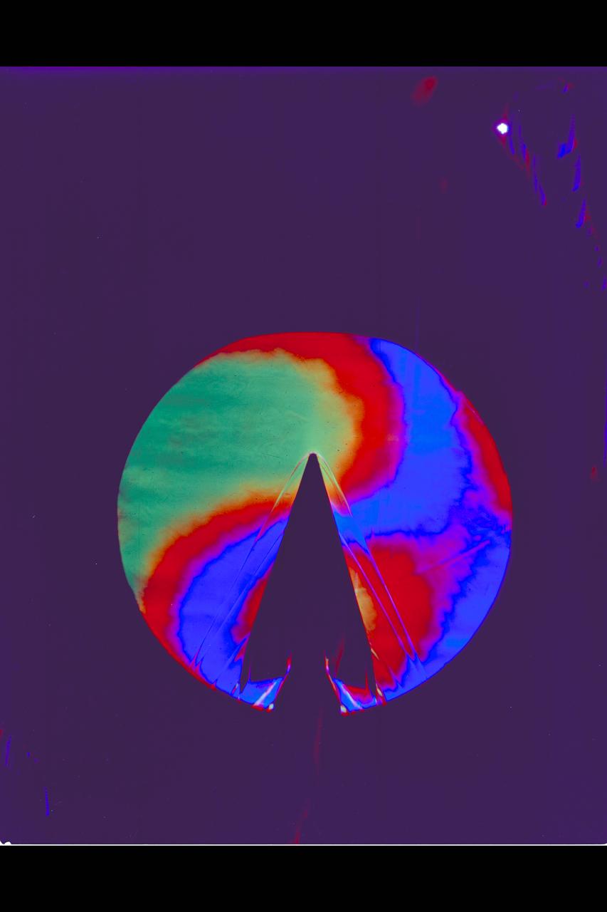
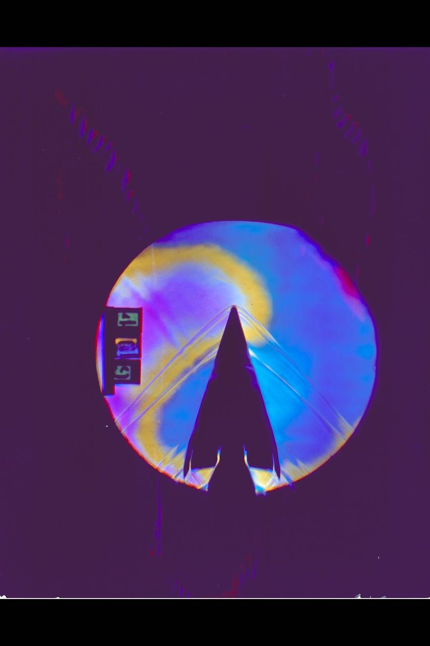
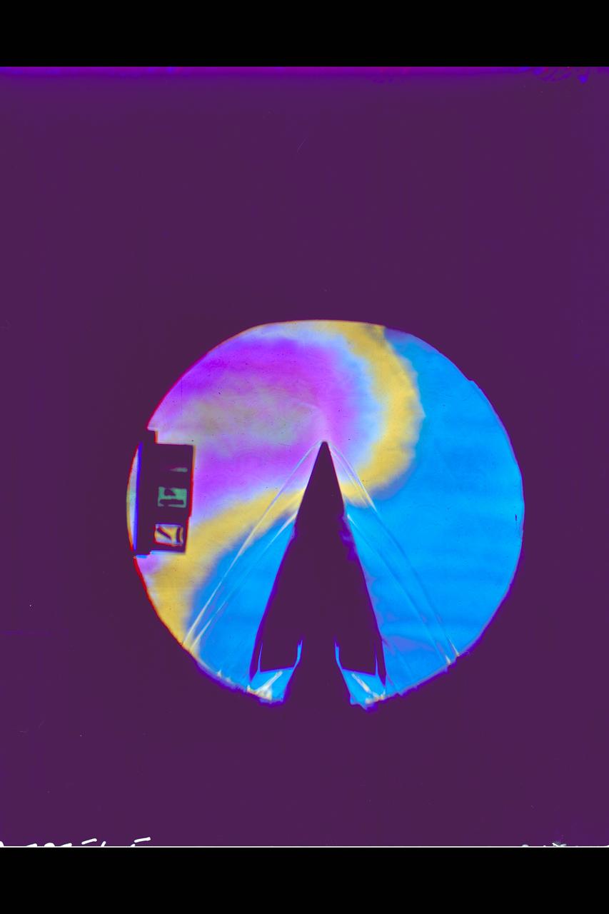
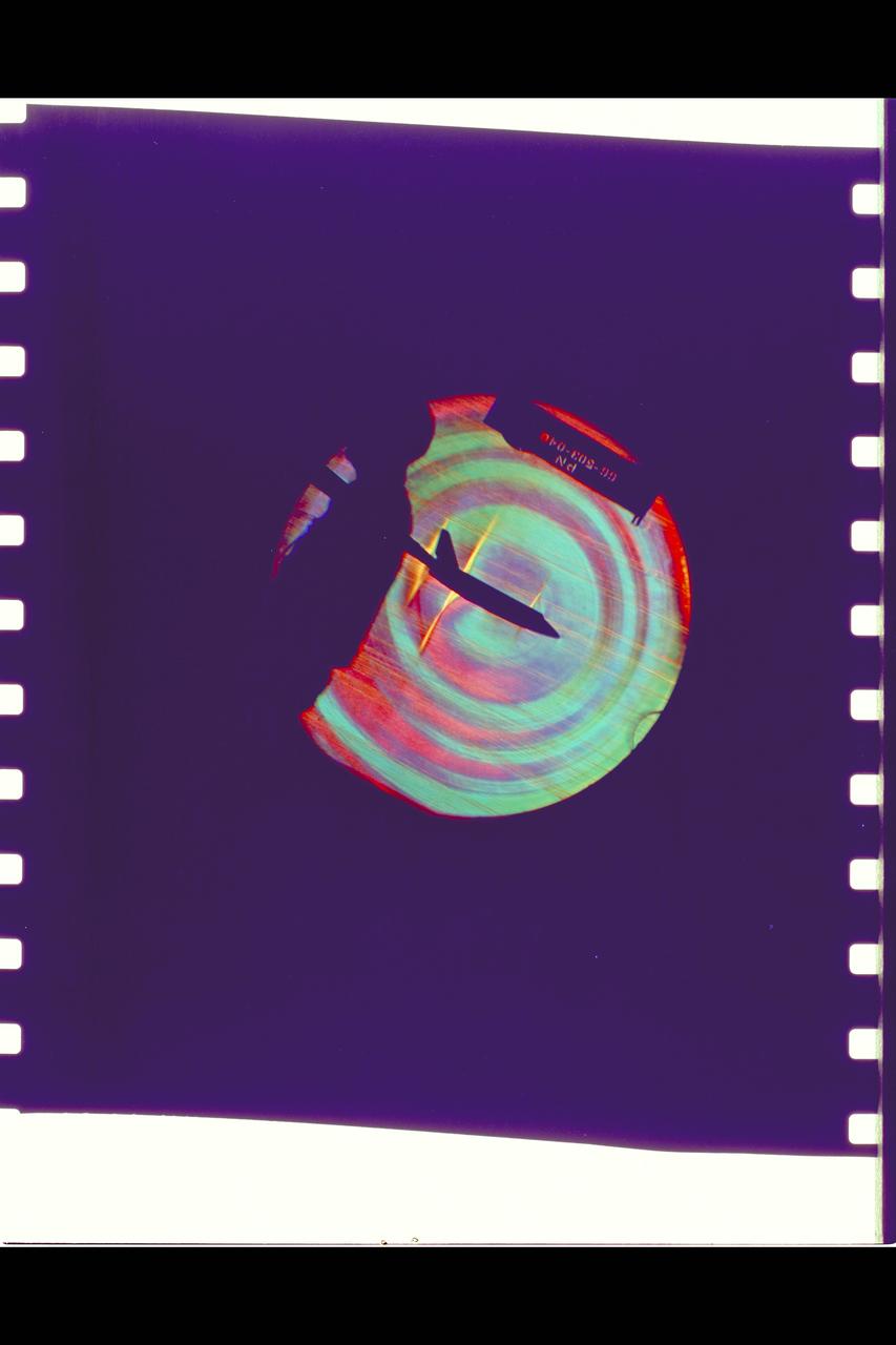
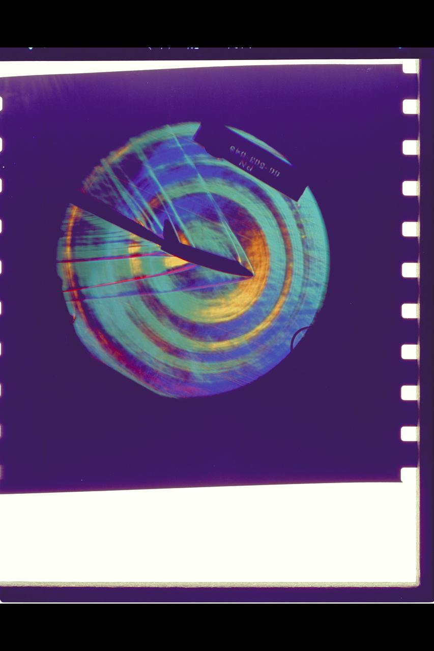
Composite image of Background Oriented Schlieren (BOS) data (contour) with a cut-out images of the T-38’s during a Mach Number 1.02 pass. The interaction of the shockwave of the trailing aircraft with the exhaust plume of the lead aircraft shows a shockwave reflection. Original recording of the pass taken in the Black Mountain Supersonic Corridor at near Edwards AFB in December of 2018. Image acquired by JT Heineck, schlieren data processed by Neal Smith.

Composite image of Background Oriented Schlieren (BOS) data (contour) with a cut-out images of the T-38’s during a Mach Number 1.02 pass. The interaction of the shockwave of the trailing aircraft with the exhaust plume of the lead aircraft shows a shockwave reflection. Original recording of the pass taken in the Black Mountain Supersonic Corridor at near Edwards AFB in December of 2018. Image acquired by JT Heineck, schlieren data processed by Neal Smith.

Composite image of Background Oriented Schlieren (BOS) data (contour) with a cut-out images of the T-38’s during a Mach Number 1.02 pass. The interaction of the shockwave of the trailing aircraft with the exhaust plume of the lead aircraft shows a shockwave reflection. Original recording of the pass taken in the Black Mountain Supersonic Corridor at near Edwards AFB in December of 2018. Image acquired by JT Heineck, schlieren data processed by Neal Smith.
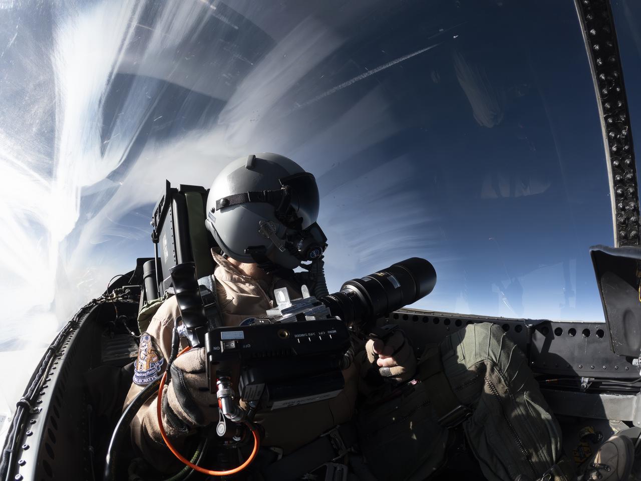
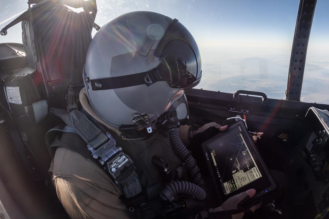
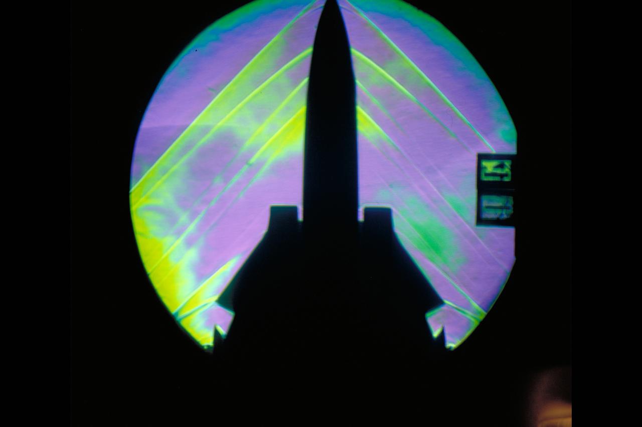
NASA Photographer Carla Thomas holds the Airborne Schlieren Photography System (ASPS), aiming it out the window in flight. The ASPS uses a photographic method called schlieren imaging, capable of visualizing changes in air density and revealing shock waves and air flow patterns around moving objects. The system is one of several tools validated during recent dual F-15 flights at NASA’s Armstrong Flight Research Center in Edwards, California, in support of NASA’s Quesst mission, ahead of the X-59’s first flight.
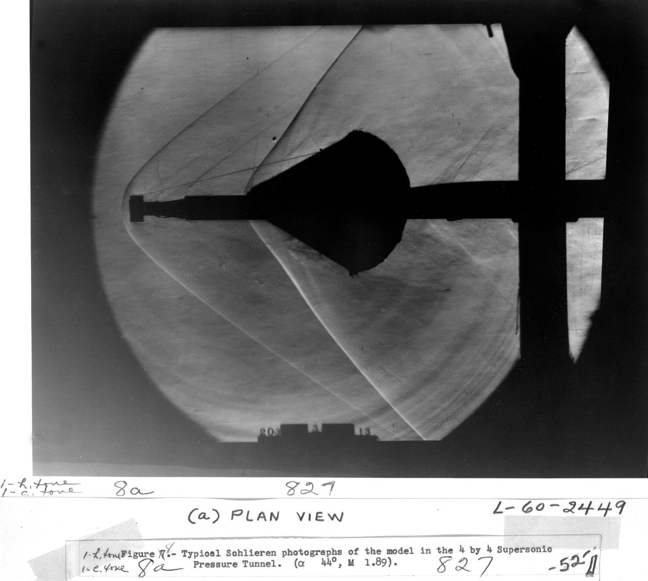
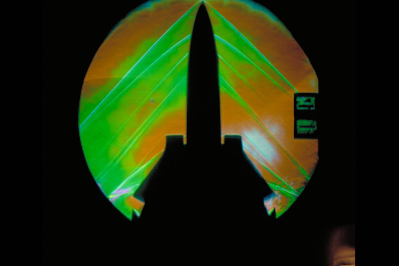
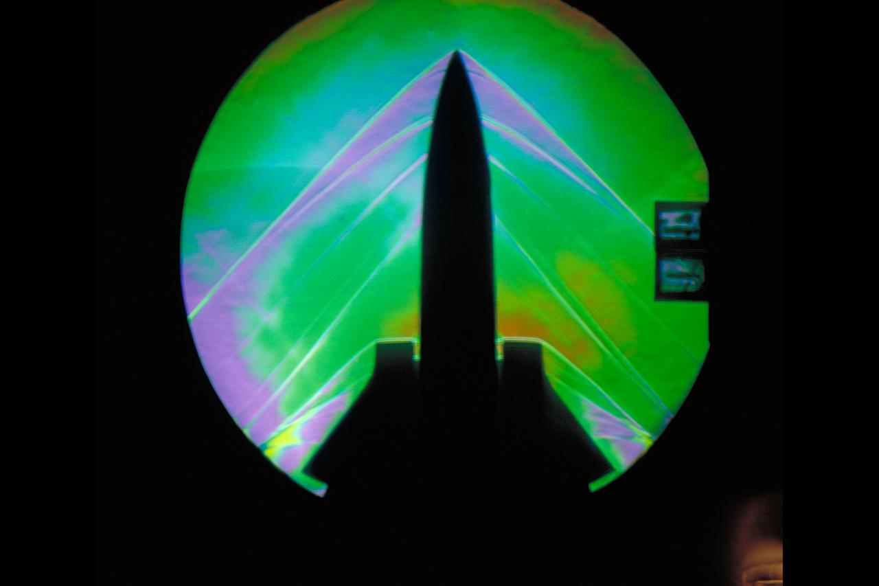
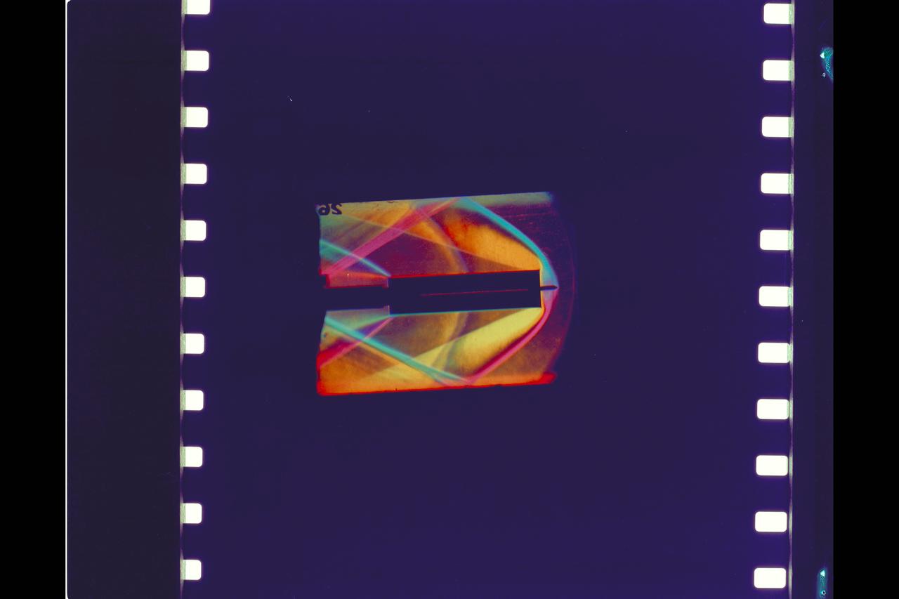
Schlieren photographs of the model in 4 x 4 Foot supersonic pressure tunnel
NASA photographer James Ross monitors the Airborne Location Integrating Geospatial Navigation System (ALIGNS) from the backseat of an F-15 near NASA’s Armstrong Flight Research Center in Edwards, California. The ALIGNS provides real-time positioning guidance between aircraft for shock wave probing and schlieren imagery capture.
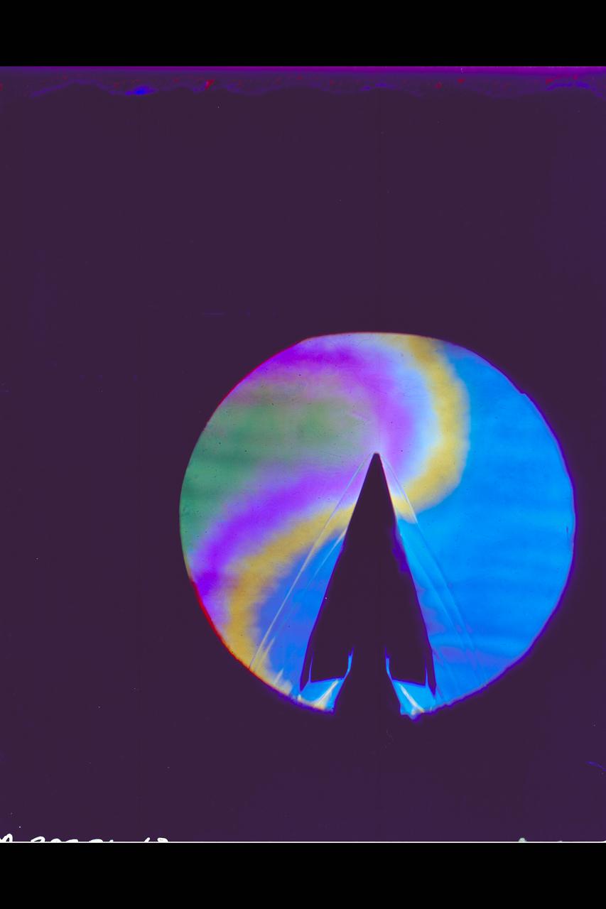
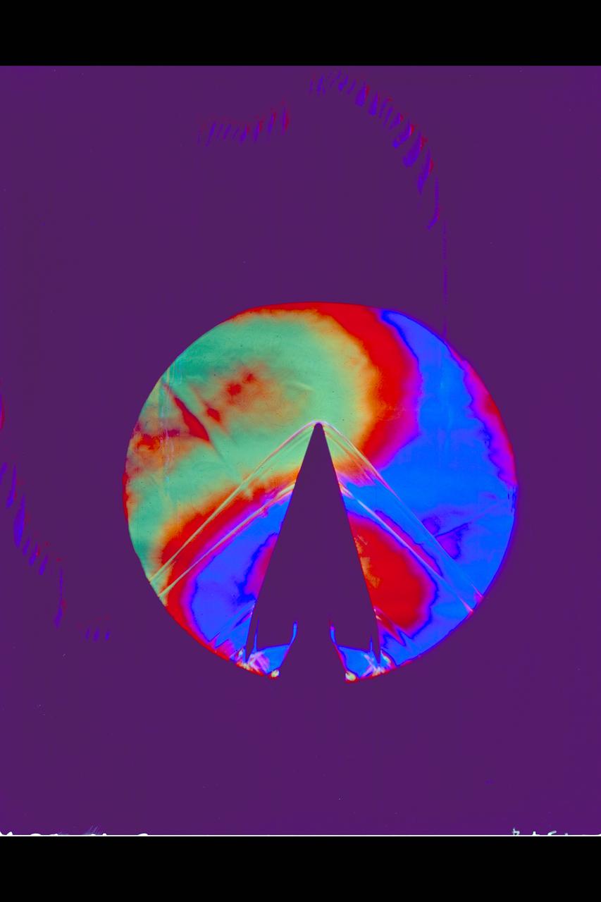
X-20 Dyna Soar on 624-A Titan III Booster: Schlieren
Schlieren of X-20 Dyna Soar mounted on 624-A Titan III Booster
X-20 Dyna Soar on 624-A Titan III Booster: Schlieren
W.T. system F-14D model Schlieren test-041 in 9x7ft w.t.

X-20 Dyna Soar on 624-A Titan III Booster: Schlieren
X-20 Dyna Soar on 624-A Titan III Booster: Schlieren

X-20 Dyna Soar on 624-A Titan III Booster: Schlieren
Schlieren of X-20 Dyna Soar mounted on 624-A Titan III Booster
X-20 Dyna Soar on 624-A Titan III Booster: Schlieren
X-20 Dyna Soar on 624-A Titan III Booster: Schlieren
W.T. system F-14D model Schlieren test-041 in 9x7ft w.t.
W.T. system F-14D model Schlieren test-041 in 9x7ft w.t.
Schlieren: Space Shuttle Plume Test-97-044-1 in 9x7ft w.t.
MSC Space Shuttle Stability and Control Characteristics. Schlieren of North American Rockwell Straight Wing orbiter approximate Mach .95
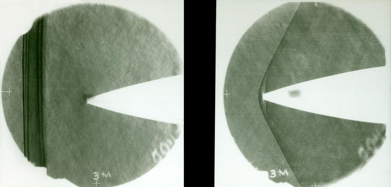
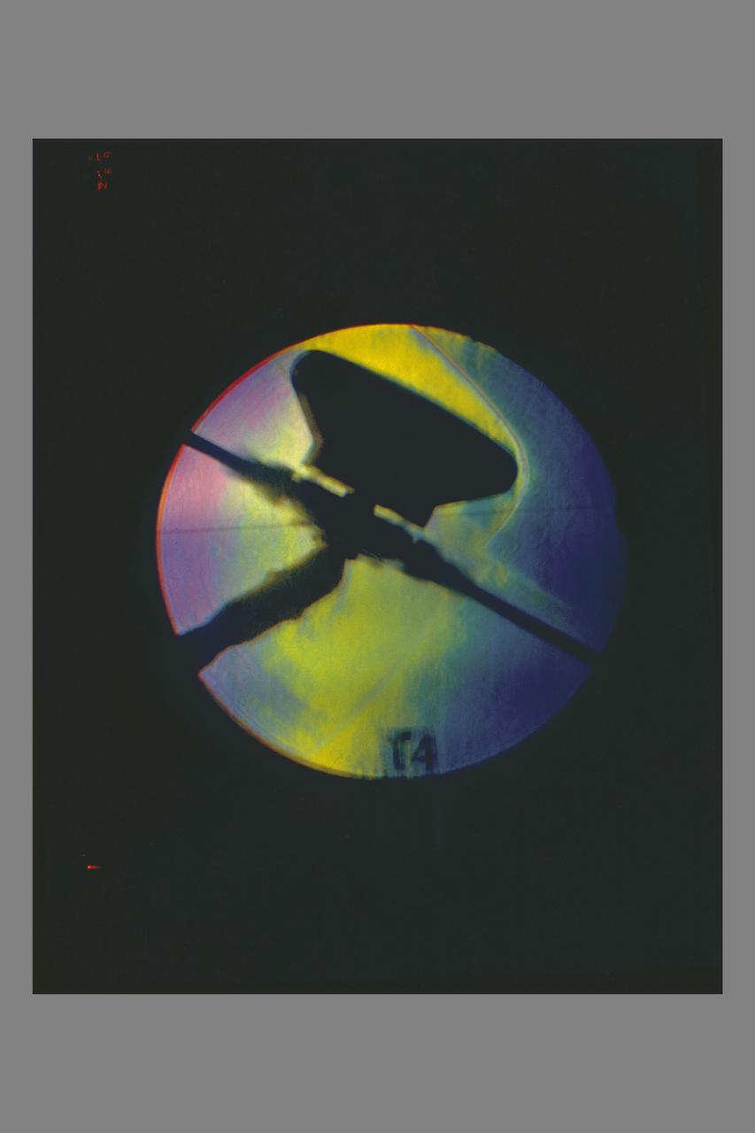
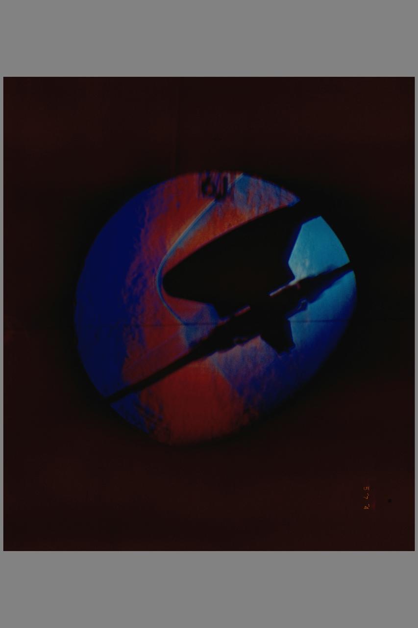
8-Foot Transonic Pressure Tunnel (TPT): Sample of Schlieren results Left - Mach 1.03 Right - Mach 1.20.
8-Foot Transonic Pressure Tunnel (TPT): Sample of Schlieren results Left - Mach 1.03 Right - Mach 1.20.
Aerodynamic Characteristics of Rotary Entry Vehicle configuration REV-1 model schlieren Testing being done at the NASA Ames Research Center, California
MSC Space Shuttle Stability and Control Characteristics. Schlieren of a Hollow Tube in 6ft. W.T. Test-66-503 Approximate Mach 1.2
Aerodynamic Characteristics of Rotary Entry Vehicle configuration REV-1 model schlieren. Testing being done at the NASA Ames Research Center, California
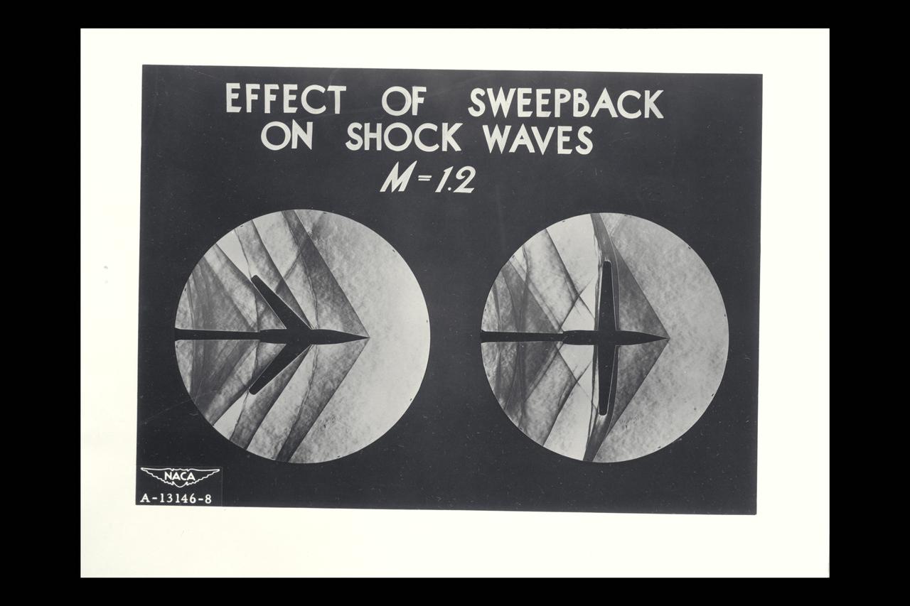
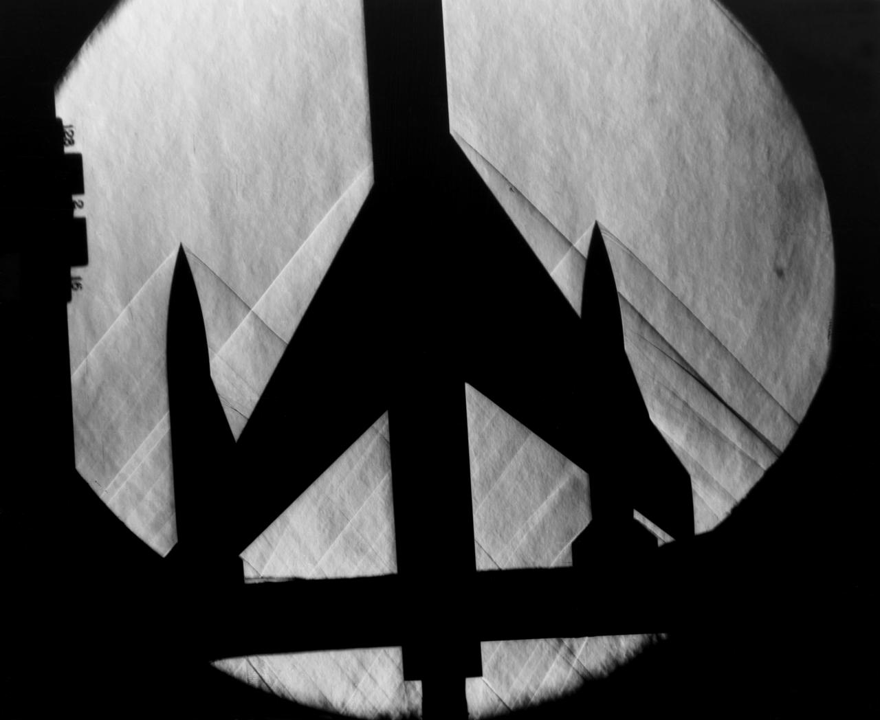
NACA Photographer/Graphic Supersonic Research: Schlieren photograph of the flow around airplane models showing effect of Sweptback on Shock Waves - M =1.2 (composite of shadowgraph samples on sweptback and straight wings
MSC Space Shuttle Stability and Control Characteristics. Schlieren of North American Rockwell Straight Wing orbiter approximate Mach .95 6ft w.t. Test-66-503
MSC Space Shuttle Stability and Control Characteristics. Schlieren of North American Rockwell Straight Wing orbiter approximate Mach .95 6ft w.t. test-66-503

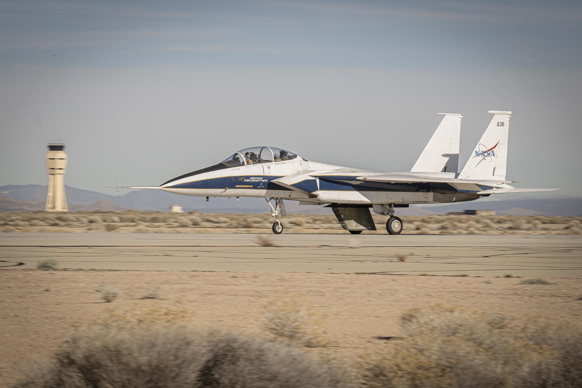
Two NASA F-15 aircraft sit on the ramp at NASA's Armstrong Flight Research Center, in Edwards, California, ahead of dual F-15 flights that validated the integration of three tools – the Airborne Schlieren Photography System (ASPS), the Airborne Location Integrating Geospatial Navigation System (ALIGNS), and shock-sensing probe. Together these tools will measure and visualize the shock waves generated by NASA's X-59.
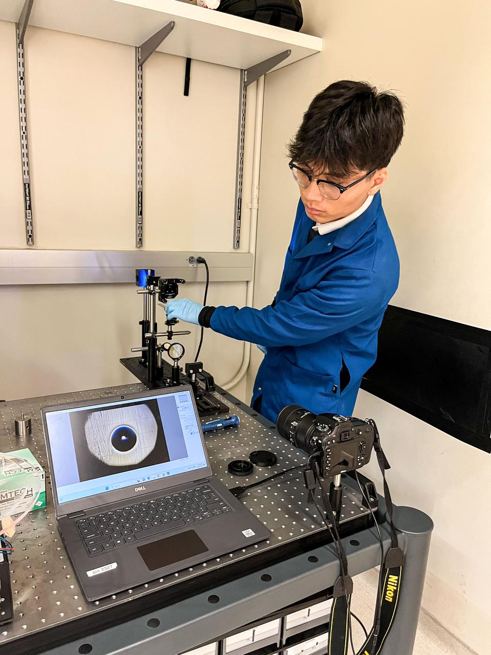
jsc2023e055884 (9/26/2023) --- Trinh Huynh uses a quantitative Schlieren system to measure the deformation of the mucus-like gel around a liquid drop. The Gaucho Lung investigation will study fluid transport within gel-coated tubes to learn more about treatment programs for respiratory distress syndrome and develop new contamination control strategies. Image courtesy of University of California, Santa Barbara.
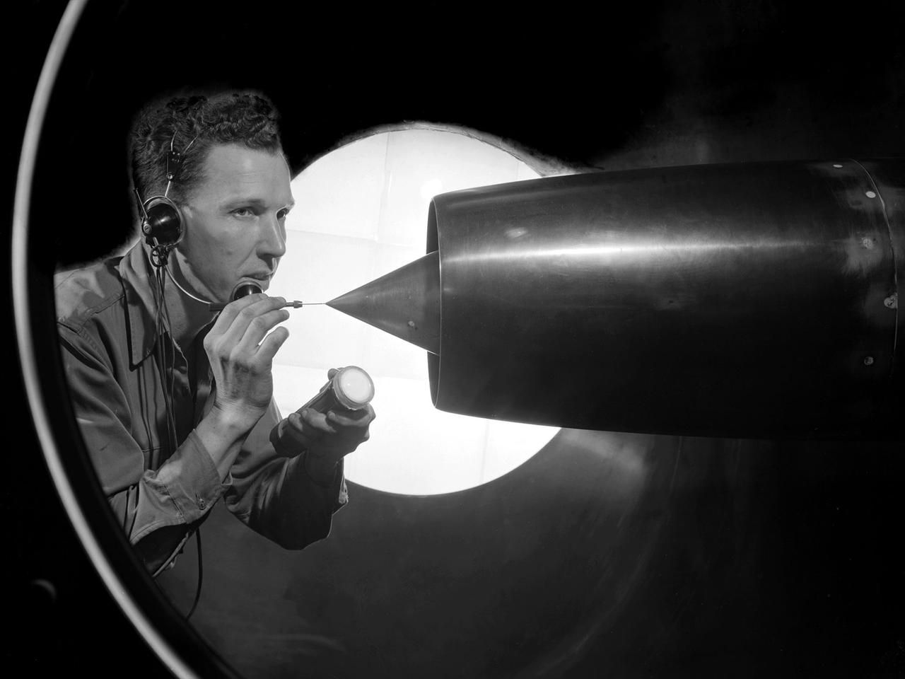
A technician at the National Advisory Committee for Aeronautics (NACA) Lewis Flight Propulsion Laboratory cleans the pitot tube on a 16-inch diameter ramjet in the 8- by 6-Foot Supersonic Wind Tunnel. Pitot tubes are a measurement device used to determine the flow velocity at a specific location in the air stream, not the average velocity of the entire wind stream. NACA Lewis was in the midst of a multi-year program to determine the feasibility of ramjets and design improvements that could be employed for all models. The advantage of the ramjet was its ability to process large volumes of combustion air, resulting in the burning of fuel at the optimal stoichiometric temperatures. This was not possible with turbojets. The higher the Mach number, the more efficient the ramjet operated. The 8- by 6 Supersonic Wind Tunnel had been in operation for just over one year when this photograph was taken. The facility was the NACA’s largest supersonic tunnel and the only facility capable of running an engine at supersonic speeds. The 8- by 6 tunnel was also equipped with a Schlieren camera system that captured the air flow gradient as it passes over the test setup. The ramjet tests in the 8- by 6 tunnel complemented the NACA Lewis investigations using aircraft, the Altitude Wind Tunnel and smaller supersonic tunnels. Researchers studied the ramjet’s performance at different speeds and varying angles -of -attack.
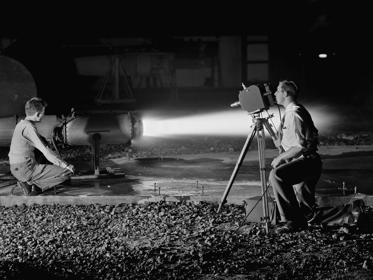
A National Advisory Committee for Aeronautics (NACA) photographer films the test of a ramjet engine at the Lewis Flight Propulsion Laboratory. The laboratory had an arsenal of facilities to test the engines and their components, and immersed itself in the study of turbojet and ramjet engines during the mid-1940s. Combustion, fuel injection, flameouts, and performance at high altitudes were of particular interest to researchers. They devised elaborate schemes to instrument the engines in order to record temperature, pressure, and other data. Many of the tests were also filmed so Lewis researchers could visually review the combustion performance along with the data. The photographer in this image was using high-speed film to document a thrust augmentation study at Lewis’ Jet Static Propulsion Laboratory. The ramjet in this photograph was equipped with a special afterburner as part of a general effort to improve engine performance. Lewis’ Photo Lab was established in 1942. The staff was expanded over the next few years as more test facilities became operational. The Photo Lab’s staff and specialized equipment have been key research tools for decades. They accompany pilots on test flights, use high-speed cameras to capture fleeting processes like combustion, and work with technology, such as the Schlieren camera, to capture supersonic aerodynamics. In addition, the group has documented construction projects, performed publicity work, created images for reports, and photographed data recording equipment.
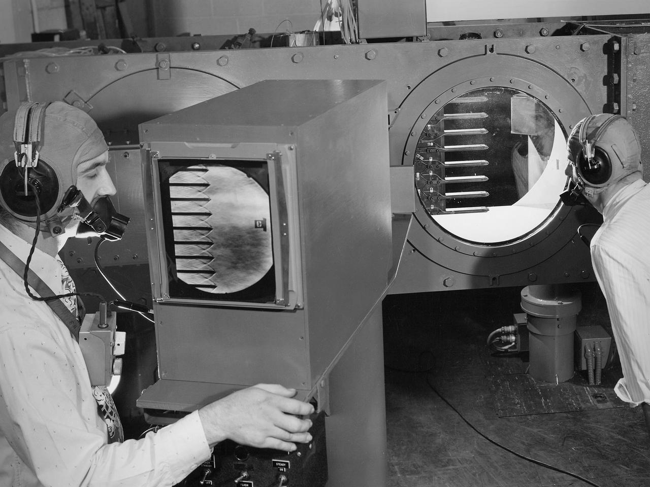
Engineers calibrate one of three small supersonic wind tunnels that were collectively referred to as the “Stack Tunnels” at the National Advisory Committee for Aeronautics (NACA) Lewis Flight Propulsion Laboratory. In late 1945 NACA Lewis reorganized its staff and began constructing a new wave of facilities to address high-speed flight and the turbojet and rocket technologies that emerged during World War II. While design work began on what would eventually become the 8- by 6-Foot Supersonic Wind Tunnel, NACA Lewis quickly built several small supersonic tunnels. These small facilities utilized the Altitude Wind Tunnel’s massive air handling equipment. Three of the small tunnels were built vertically on top of each other and thus were known as the Stack Tunnels. The first of the Stack Tunnels was an 18- by 18-inch tunnel that began operating in August 1945 at speeds up to Mach 1.91. The second tunnel, whose 24- by 24-inch test section is shown here, was added in 1949. It could generate air flows up to Mach 3.96. A third tunnel with an 18- by 18-inch test section began operating in 1951 with speeds up to Mach 3.05. The small tunnels were used until the early 1960s to study the aerodynamic characteristics of supersonic inlets and exits. The technician to the left in this photograph is operating a Schlieren camera to view the air flow dynamics inside the 24- by 24-inch test section. The technician on the right is viewing the pronged test article through the circular window. They are calibrating the tunnel and its equipment to prepare for the initial test runs.
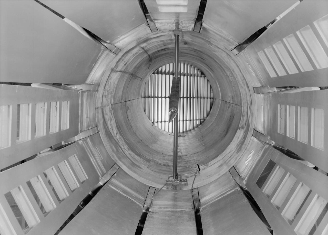
Interior view of the slotted throat test section installed in the 8-Foot High Speed Tunnel (HST) in 1950. The slotted region is about 160 inches in length. In this photograph, the sting-type model support is seen straight on. In a NASA report, the test section is described as follows: The test section of the Langley 8-foot transonic tunnel is dodecagonal in cross section and has a cross-sectional area of about 43 square feet. Longitudinal slots are located between each of the 12 wall panels to allow continuous operation through the transonic speed range. The slots contain about 11 percent of the total periphery of the test section. Six of the twelve panels have windows in them to allow for schlieren observations. The entire test section is enclosed in a hemispherical shaped chamber. John Becker noted that the tunnel s final achievement was the development and use in routine operations of the first transonic slotted throat. The investigations of wing-body shapes in this tunnel led to Whitcomb s discovery of the transonic area rule. James Hansen described the origins of the the slotted throat as follows: In 1946 Langley physicist Ray H. Wright conceived a way to do transonic research effectively in a wind tunnel by placing slots in the throat of the test section. The concept for what became known as the slotted-throat or slotted-wall tunnel came to Wright not as a solution to the chronic transonic problem, but as a way to get rid of wall interference (i.e., the mutual effect of two or more meeting waves or vibrations of any kind caused by solid boundaries) at subsonic speeds. For most of the year before Wright came up with this idea, he had been trying to develop a theoretical understanding of wall interference in the 8-Foot HST, which was then being repowered for Mach 1 capability. When Wright presented these ideas to John Stack, the response was enthusiastic but neither Wright nor Stack thought of slotted-throats as a solution to the transonic problem, only the wall interference problem. It was an accidental discovery which showed that slotted throats might solve the transonic problem. Most engineers were skeptical but Stack persisted. Initially, plans were to modify the 16-Foot tunnel but in the spring of 1948, Stack announced that the 8-Foot HST would also be modified. As Hansen notes: The 8-Foot HST began regular transonic operations for research purposes on 6 October 1950. The concept was a success and led to plans for a new wind tunnel which would be known as the 8-Foot Transonic Pressure Tunnel. -- Published in U.S., National Advisory Committee for Aeronautics, Characteristics of Nine Research Wind Tunnels of the Langley Aeronautical Laboratory, 1957, pp. 17, 22 James R. Hansen, Engineer in Charge, NASA SP-4305, p. 454 and Chapter 11, The Slotted Tunnel and the Area Rule.
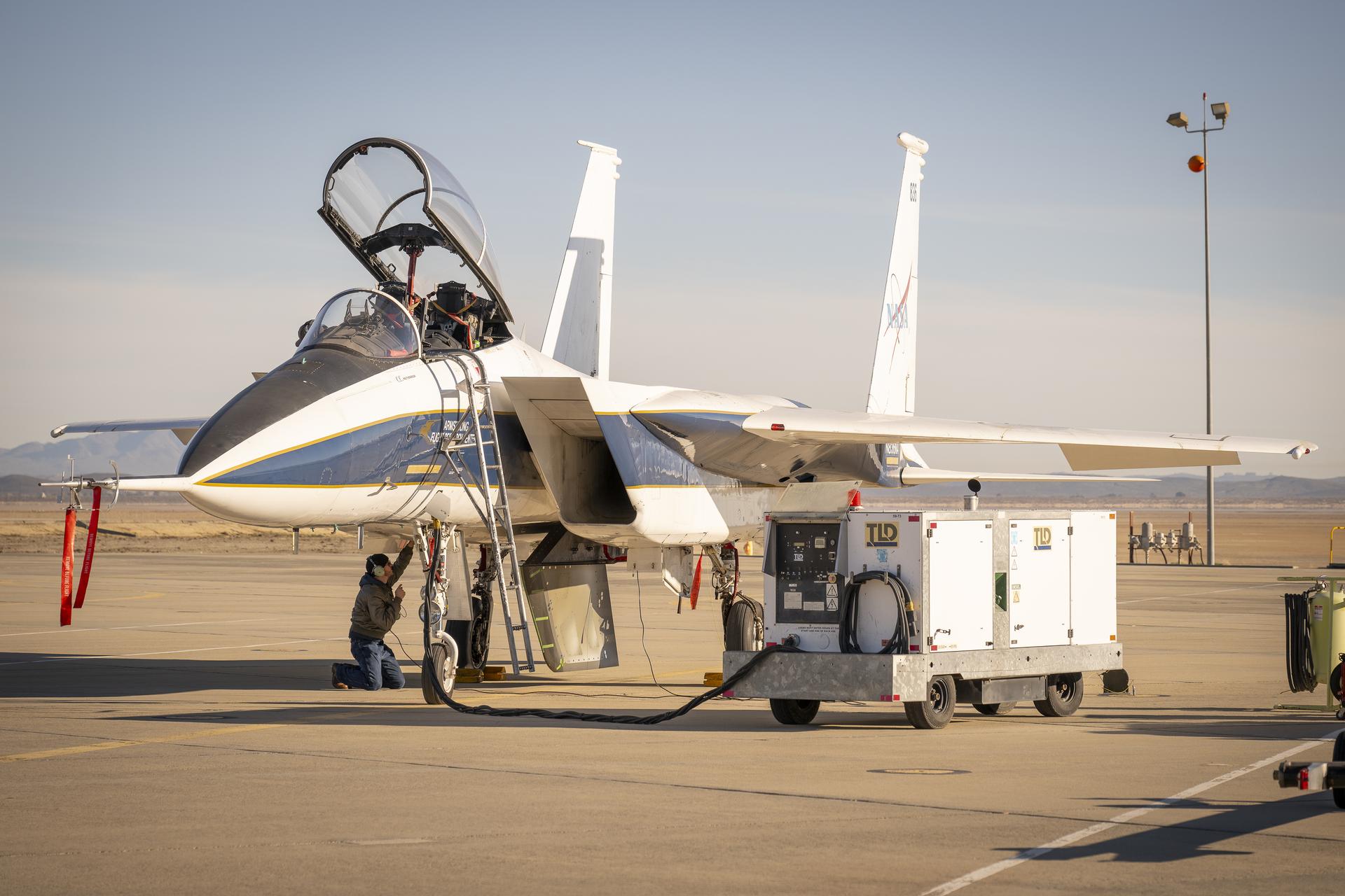
NASA ground crew prepares the agency’s F-15 research aircraft and Cross Flow Attenuated Natural Laminar Flow (CATNLF) test article ahead of its first high-speed taxi test on Tuesday, Jan. 12, 2026, at NASA’s Armstrong Flight Research Center in Edwards, California. The CATNLF design aims to reduce drag on wing surfaces to improve efficiency and, in turn, reduce fuel burn.
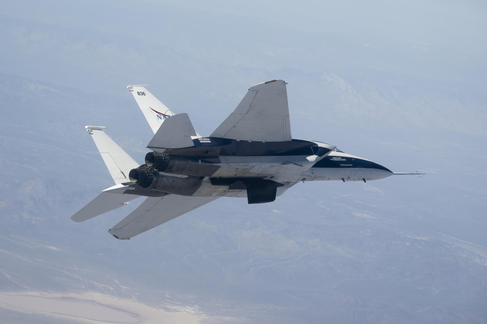
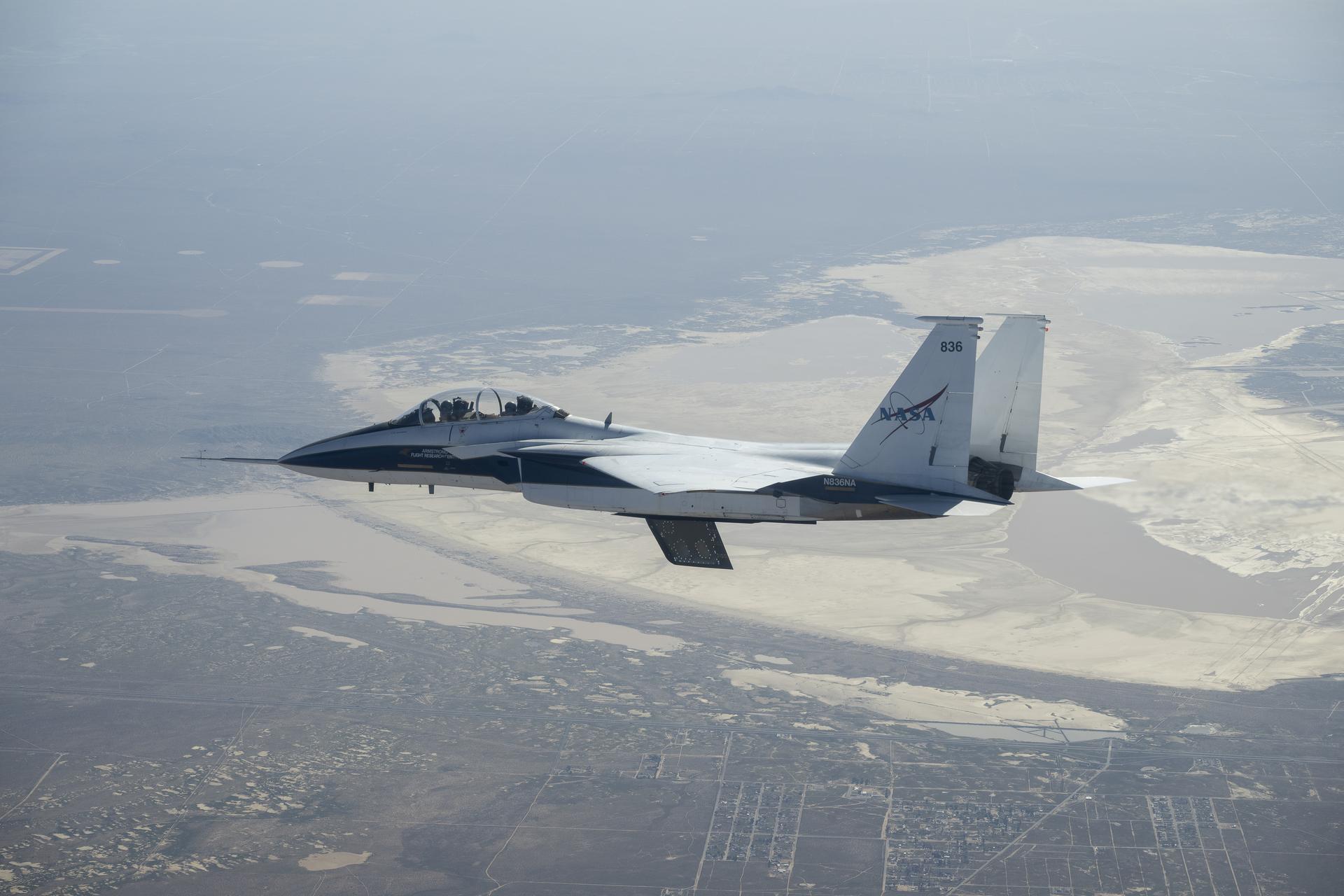
NASA’s Crossflow Attenuated Natural Laminar Flow (CATNLF) scale-model wing flies on a NASA F-15 research jet during a test flight from NASA’s Armstrong Flight Research Center in Edwards, California. The CATNLF technology is designed to maintain smooth airflow, known as laminar flow. NASA will continue flight tests to collect data that validates the CATNLF design and its potential to improve laminar flow, reducing drag and lowering fuel costs for future commercial aircraft.
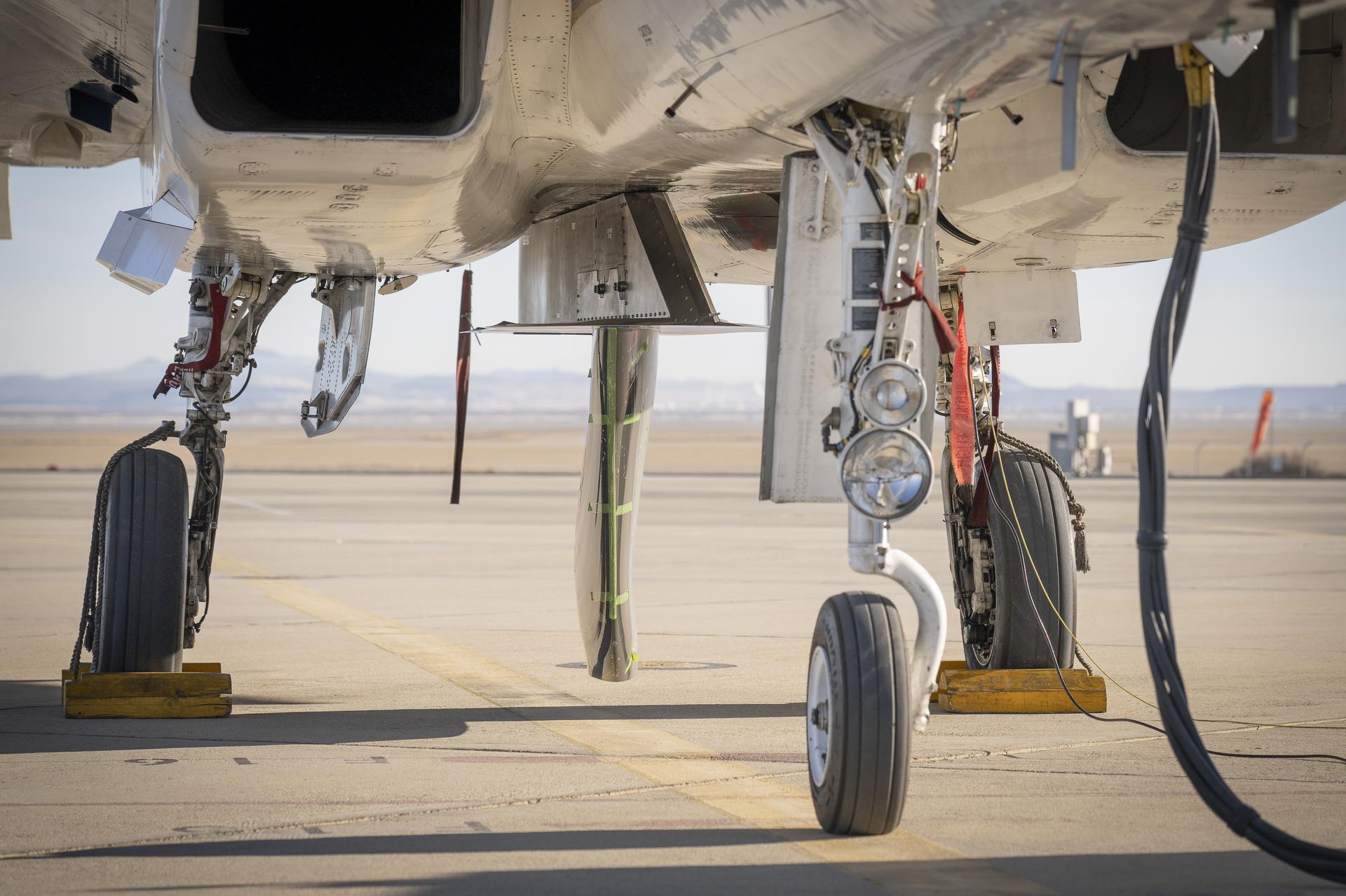
NASA’s Cross Flow Attenuated Natural Laminar Flow test article is mounted beneath the agency’s F-15 research aircraft ahead of the design’s high-speed taxi test on Tuesday, Jan. 12, 2026, at NASA’s Armstrong Flight Research Center in Edwards, California. The 3-foot-tall scale model is designed to increase a phenomenon known as laminar flow and reduce drag, improving efficiency in large, swept wings like those found on most commercial aircraft.
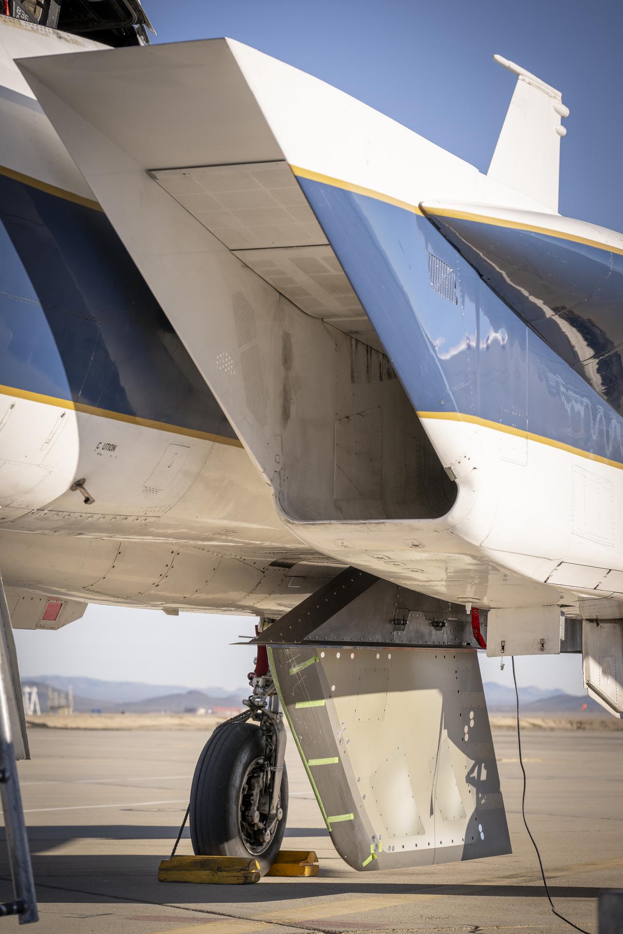
NASA’s Cross Flow Attenuated Natural Laminar Flow test article is mounted beneath the agency’s F-15 research aircraft ahead of the design’s high-speed taxi test on Tuesday, Jan. 12, 2026, at NASA’s Armstrong Flight Research Center in Edwards, California. The 3-foot-tall scale model is designed to increase a phenomenon known as laminar flow and reduce drag, improving efficiency in large, swept wings like those found on most commercial aircraft.
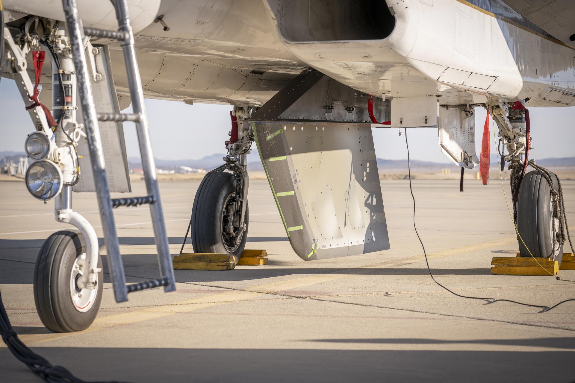
NASA’s Cross Flow Attenuated Natural Laminar Flow test article is mounted beneath the agency’s F-15 research aircraft ahead of the design’s high-speed taxi test on Tuesday, Jan. 12, 2026, at NASA’s Armstrong Flight Research Center in Edwards, California. The 3-foot-tall scale model is designed to increase a phenomenon known as laminar flow and reduce drag, improving efficiency in large, swept wings like those found on most commercial aircraft.
NASA’s Cross Flow Attenuated Natural Laminar Flow (CATNLF) scale model completes its first major milestone – high-speed taxi test – Tuesday, Jan. 12, 2026, at Edwards Air Force Base in California. NASA’s F-15 research aircraft, with the 3-foot-tall test article mounted on its underside, reached speeds of approximately 144 mph during testing. If successful, the technology could be applied to future commercial aircraft to improve efficiency and potentially reduce fuel consumption.
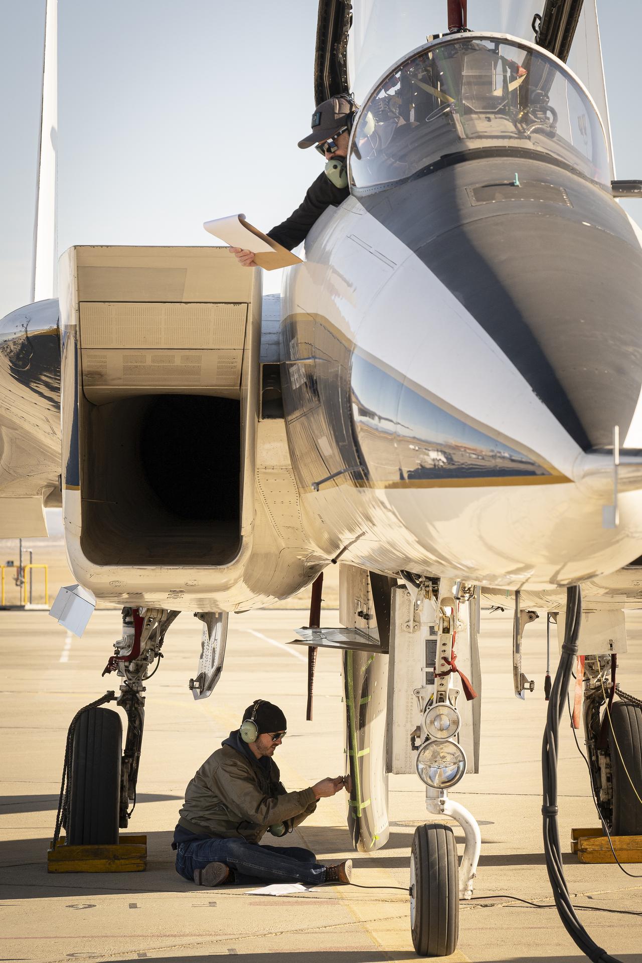
NASA ground crew prepares the agency’s F-15 research aircraft and Cross Flow Attenuated Natural Laminar Flow (CATNLF) test article ahead of its first high-speed taxi test on Tuesday, Jan. 12, 2026, at NASA’s Armstrong Flight Research Center in Edwards, California. The CATNLF design aims to reduce drag on wing surfaces to improve efficiency and, in turn, reduce fuel burn.
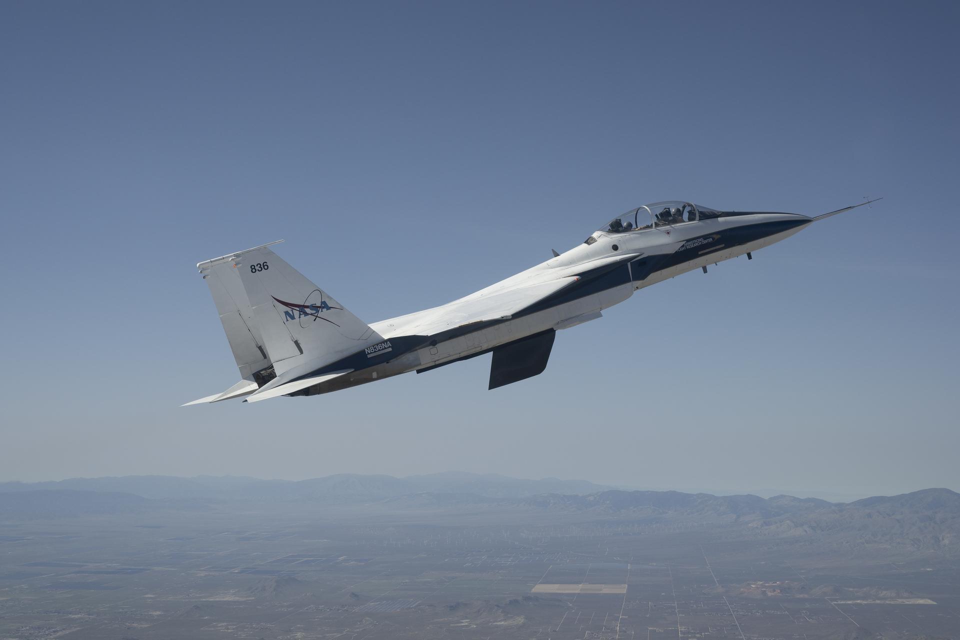
NASA’s Crossflow Attenuated Natural Laminar Flow (CATNLF) scale-model wing flies for the first time on a NASA F-15 research jet during a test flight from NASA’s Armstrong Flight Research Center in Edwards, California. The 75-minute flight confirmed the aircraft could maneuver safely with the approximately 3-foot-tall test article mounted beneath it. NASA will continue flight tests to collect data that validates the CATNLF design and its potential to improve laminar flow, reducing drag and lowering fuel costs for future commercial aircraft.
NASA’s Crossflow Attenuated Natural Laminar Flow (CATNLF) scale-model wing flies for the first time on a NASA F-15 research jet during a test flight from NASA’s Armstrong Flight Research Center in Edwards, California. The 75-minute flight confirmed the aircraft could maneuver safely with the approximately 3-foot-tall test article mounted beneath it. NASA will continue flight tests to collect data that validates the CATNLF design and its potential to improve laminar flow, reducing drag and lowering fuel costs for future commercial aircraft.
NASA’s Cross Flow Attenuated Natural Laminar Flow (CATNLF) scale model completes its first major milestone – high-speed taxi test – Tuesday, Jan. 12, 2026, at Edwards Air Force Base in California. NASA’s F-15 research aircraft, with the 3-foot-tall test article mounted on its underside, reached speeds of approximately 144 mph during testing. If successful, the technology could be applied to future commercial aircraft to improve efficiency and potentially reduce fuel consumption.
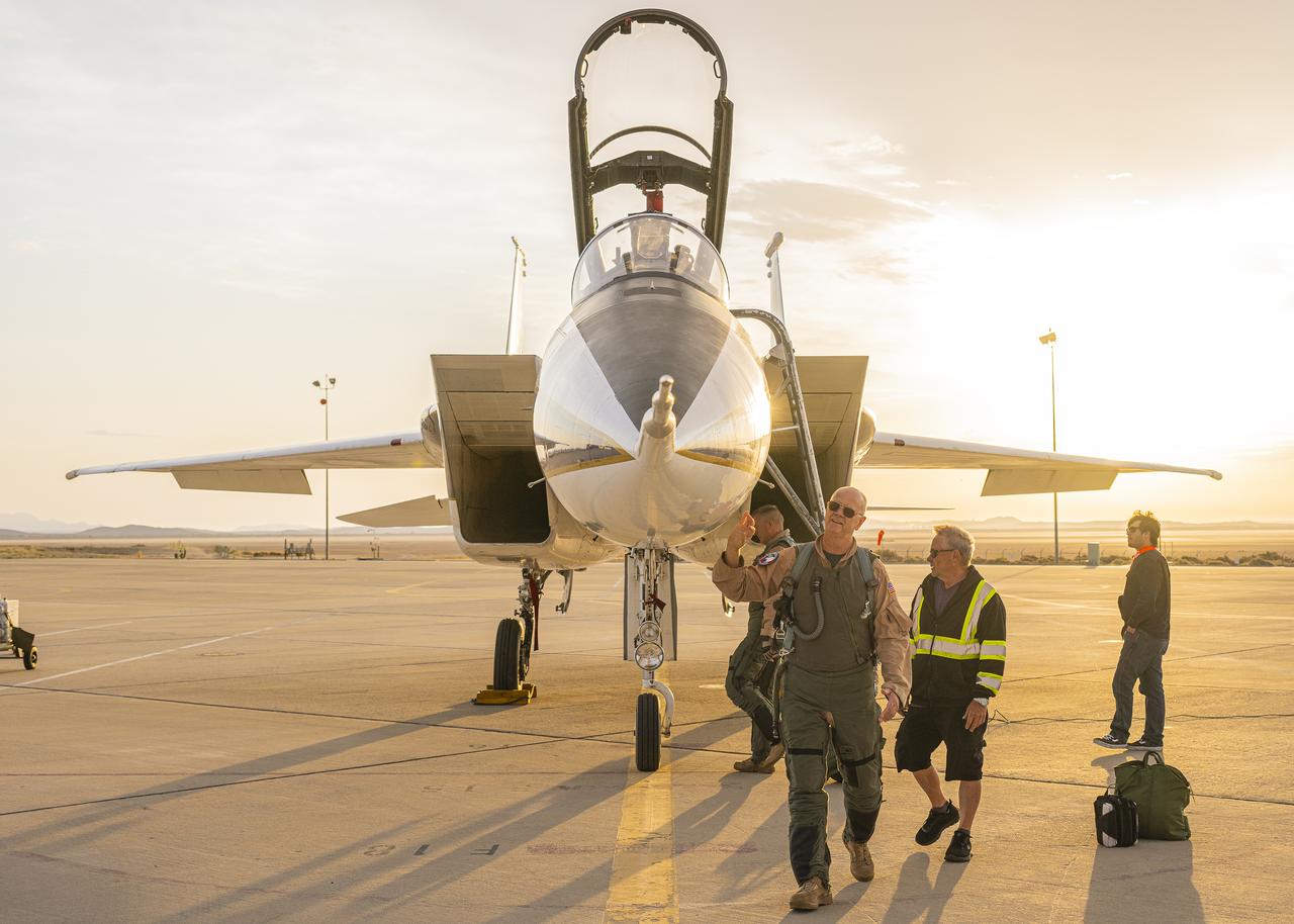
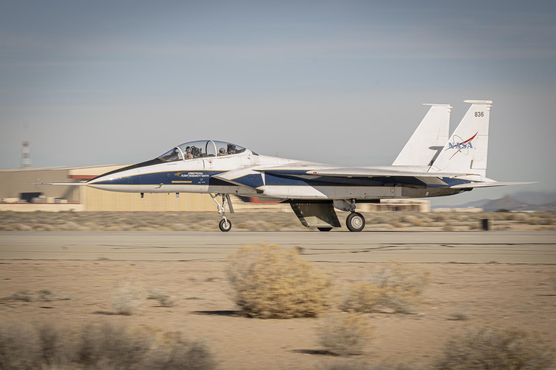
NASA test pilot Nils Larson walks around an F-15B research aircraft for a rehearsal flight supporting the agency’s Quesst mission at NASA’s Armstrong Flight Research Center in Edwards, California. The flight was part of a full-scale dress rehearsal for Phase 2 of the mission, which will eventually measure quiet sonic thumps generated by the X-59. The flight series helped NASA teams refine procedures and practice data collection ahead of future X-59 flights.
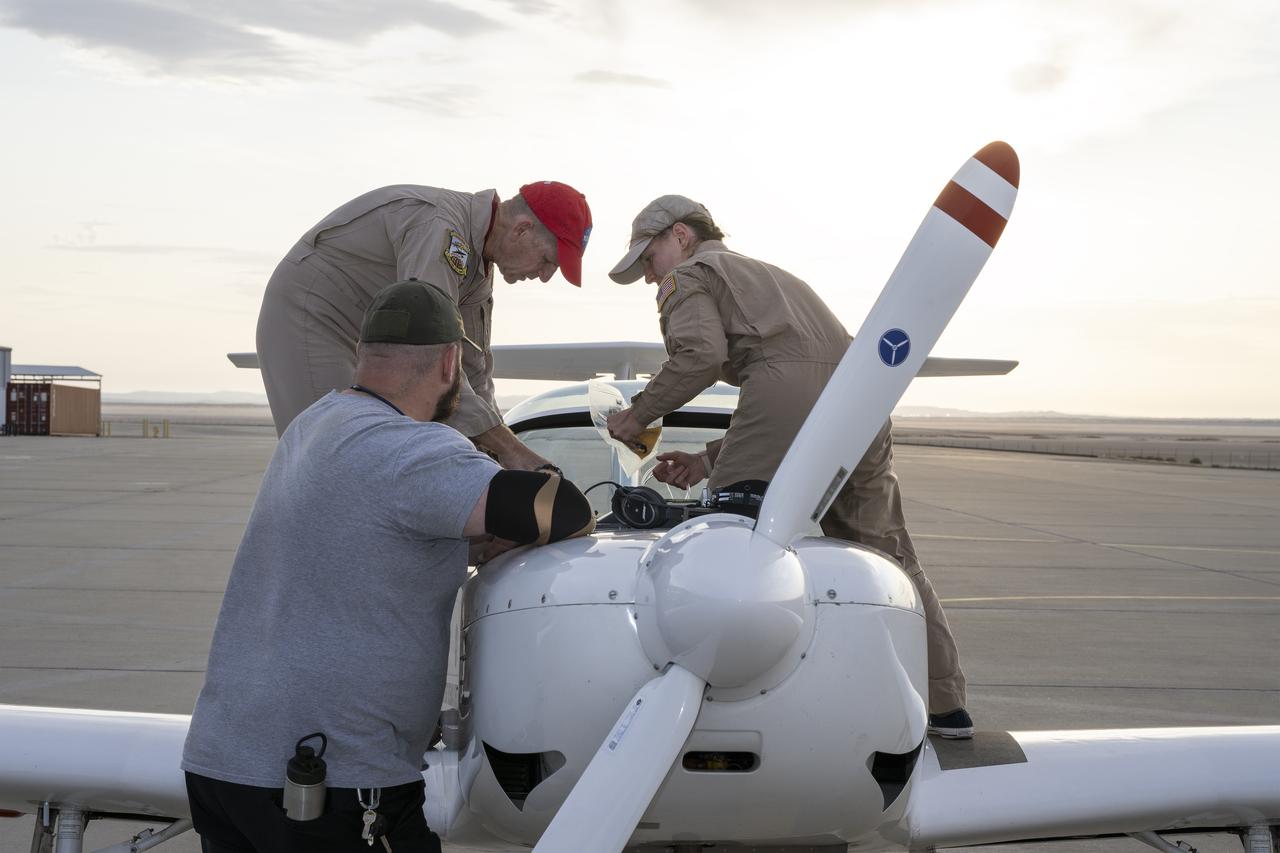
A NASA TG-14 glider aircraft is prepared for flight at NASA’s Armstrong Flight Research Center in Edwards, California, in support of the agency’s Quesst mission. The aircraft is equipped with onboard microphones to capture sonic boom noise generated during rehearsal flights, helping researchers measure the acoustic signature of supersonic aircraft closer to the ground.
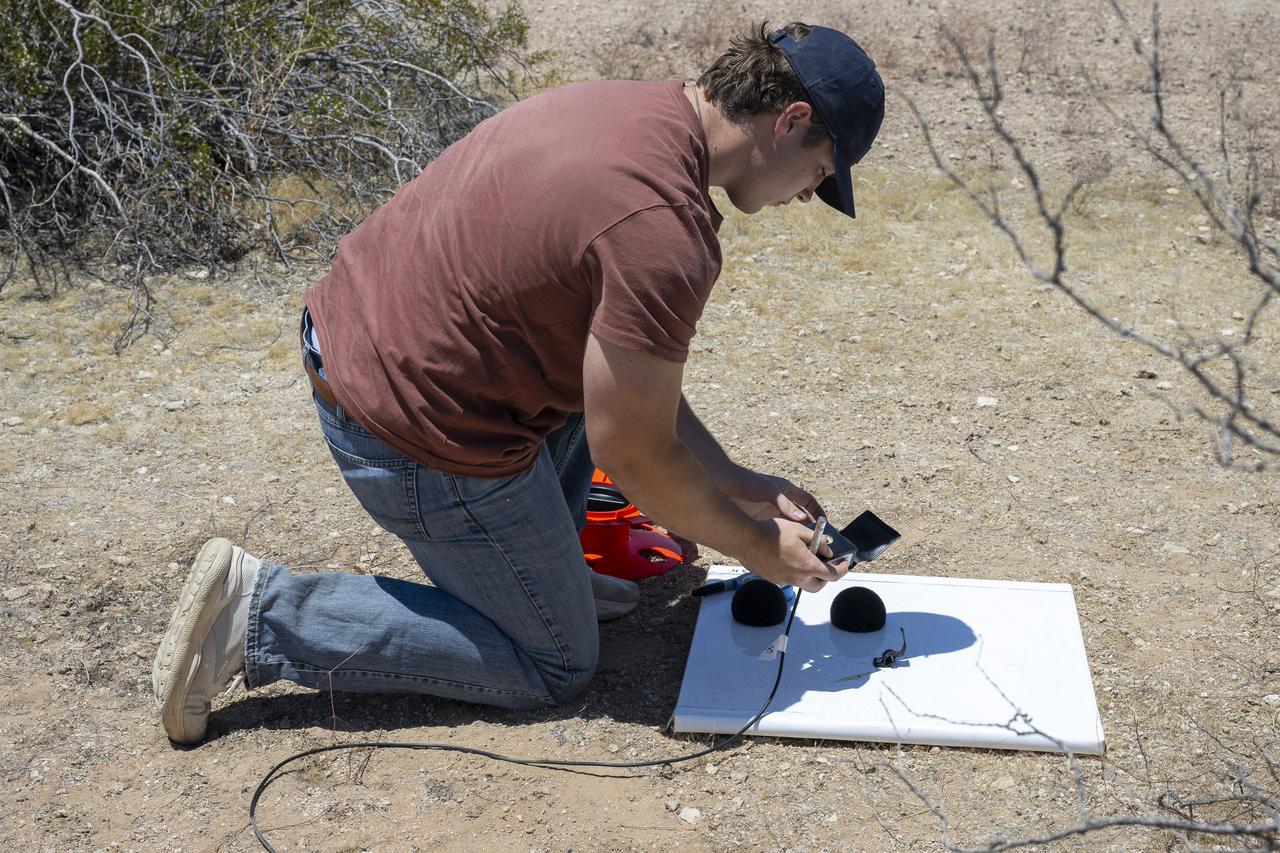
A NASA intern sets up ground recording system (GRS) units in California’s Mojave Desert during a Phase 2 rehearsal of the agency’s Quesst mission. The GRS units were placed across miles of desert terrain to capture the acoustic signature of supersonic aircraft during rehearsal flights and in preparation for the start of the actual tests.
NASA's F-15D research aircraft conducts a calibration flight of a shock-sensing probe near NASA’s Armstrong Flight Research Center in Edwards, California. The shock-sensing probe is designed to measure the signature and strength of shock waves in flight. The probe was validated during dual F-15 flights and will be flown behind NASA’s X-59 to measure small pressure changes caused by shock waves in support of the agency's Quesst mission.