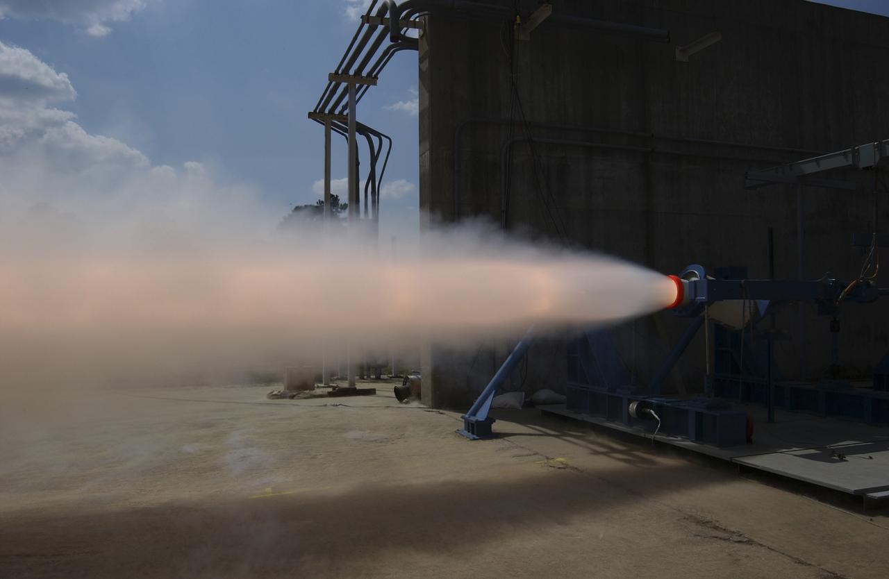
This photograph depicts a hot fire test of the Shuttle Booster Separation Motor (BSM) at the Marshall Space Flight Center (MSFC) test stand 116. The objective of the test was to test the aft heat seal in flight configuration. The function of the motor is to separate the Shuttle vehicle from the boosters that carry it into space.
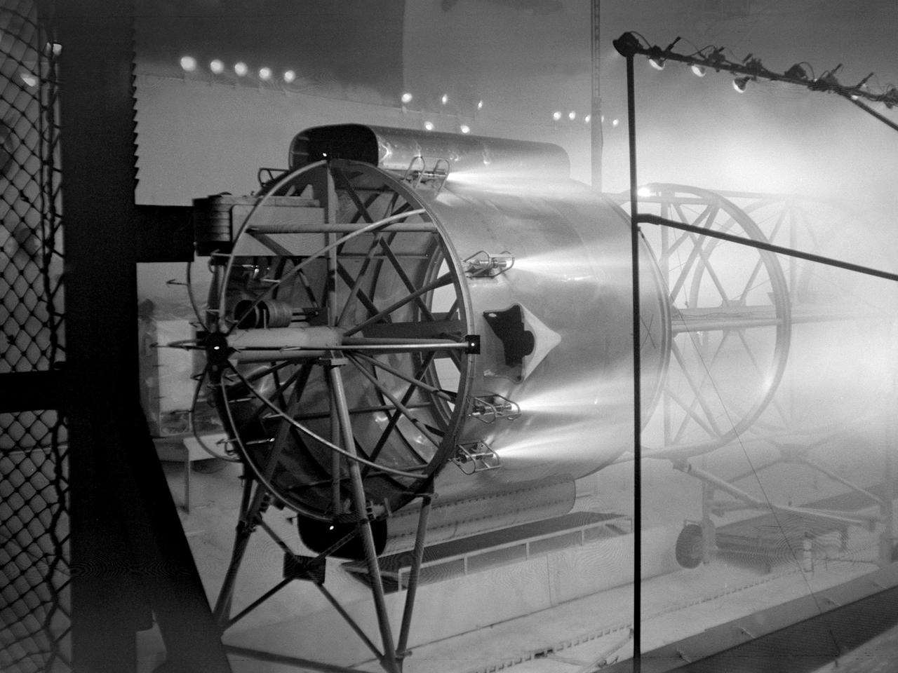
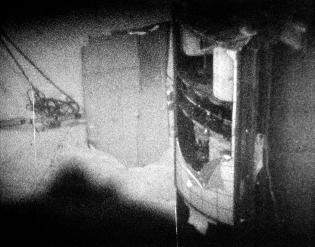
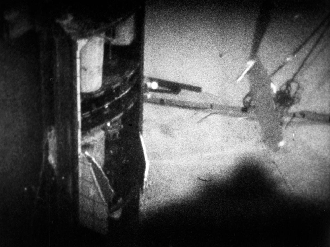
An Atlas/Centaur mass model undergoes a separation test inside the Space Power Chambers at NASA Lewis Research Center. Lewis was in the midst of an extensive effort to prepare the Centaur second-stage rocket for its missions to send the Surveyor spacecraft to the moon as a precursor to the Apollo missions. As part of these preparations, Lewis management decided to convert its Altitude Wind Tunnel into two large test chambers—the Space Power Chambers. The conversion included the removal of the tunnel’s internal components and the insertion of bulkheads to seal off the new chambers within the tunnel. One chamber could simulate conditions found at 100 miles altitude, while this larger chamber simulated the upper atmosphere. In this test series, researchers wanted to verify that the vehicle’s retrorockets would properly separate the Centaur from the Atlas. The model was suspended horizontally on a trolley system inside chamber. A net was hung at one end to catch the jettisoned Atlas model. The chamber atmosphere was reduced to a pressure altitude of 100,000 feet, and high-speed cameras were synchronized to the ignition of the retrorockets. The simulated Centaur is seen here jettisoning from the Atlas out of view to the right. The study resulted in a new jettison method that would significantly reduce the separation time and thus minimize the danger of collision between the two stages during separation.
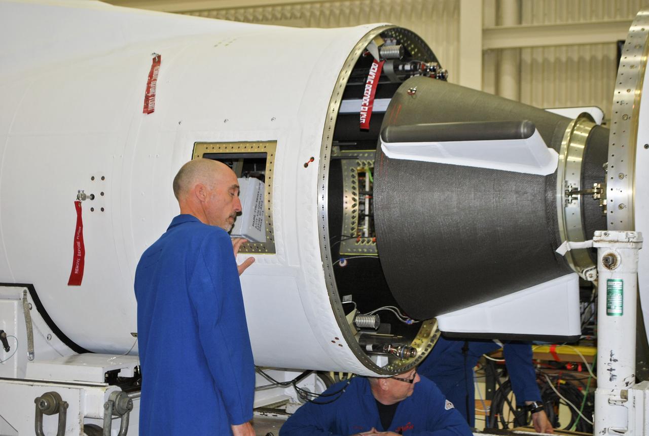
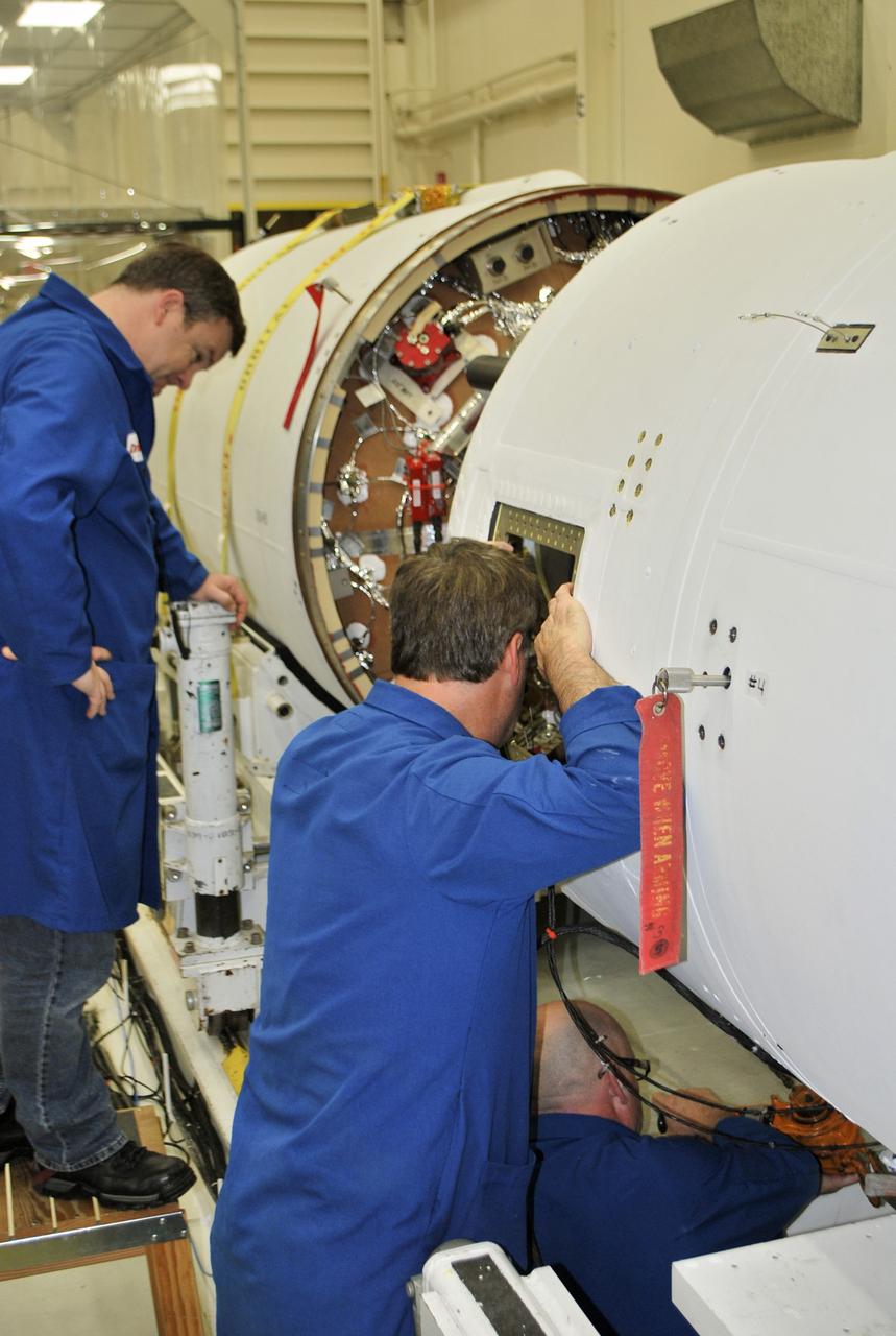
Under the goals of the Vision for Space Exploration, Ares I is a chief component of the cost-effective space transportation infrastructure being developed by NASA's Constellation Program. This transportation system will safely and reliably carry human explorers back to the moon, and then onward to Mars and other destinations in the solar system. The Ares I effort includes multiple project element teams at NASA centers and contract organizations around the nation, and is managed by the Exploration Launch Projects Office at NASA's Marshall Space Flight Center (MFSC). ATK Launch Systems near Brigham City, Utah, is the prime contractor for the first stage booster. ATK's subcontractor, United Space Alliance of Houston, is designing, developing and testing the parachutes at its facilities at NASA's Kennedy Space Center in Florida. NASA's Johnson Space Center in Houston hosts the Constellation Program and Orion Crew Capsule Project Office and provides test instrumentation and support personnel. Together, these teams are developing vehicle hardware, evolving proven technologies, and testing components and systems. Their work builds on powerful, reliable space shuttle propulsion elements and nearly a half-century of NASA space flight experience and technological advances. Ares I is an inline, two-stage rocket configuration topped by the Crew Exploration Vehicle, its service module, and a launch abort system. In this HD video image, an Ares I x-test involves the upper stage separating from the first stage. This particular test was conducted at the NASA Langley Research Center in July 2007. (Highest resolution available)
Under the goals of the Vision for Space Exploration, Ares I is a chief component of the cost-effective space transportation infrastructure being developed by NASA's Constellation Program. This transportation system will safely and reliably carry human explorers back to the moon, and then onward to Mars and other destinations in the solar system. The Ares I effort includes multiple project element teams at NASA centers and contract organizations around the nation, and is managed by the Exploration Launch Projects Office at NASA's Marshall Space Flight Center (MFSC). ATK Launch Systems near Brigham City, Utah, is the prime contractor for the first stage booster. ATK's subcontractor, United Space Alliance of Houston, is designing, developing and testing the parachutes at its facilities at NASA's Kennedy Space Center in Florida. NASA's Johnson Space Center in Houston hosts the Constellation Program and Orion Crew Capsule Project Office and provides test instrumentation and support personnel. Together, these teams are developing vehicle hardware, evolving proven technologies, and testing components and systems. Their work builds on powerful, reliable space shuttle propulsion elements and nearly a half-century of NASA space flight experience and technological advances. Ares I is an inline, two-stage rocket configuration topped by the Crew Exploration Vehicle, its service module, and a launch abort system. In this HD video image, an Ares I x-test involves the upper stage separating from the first stage. This particular test was conducted at the NASA Langley Research Center in July 2007. (Highest resolution available)
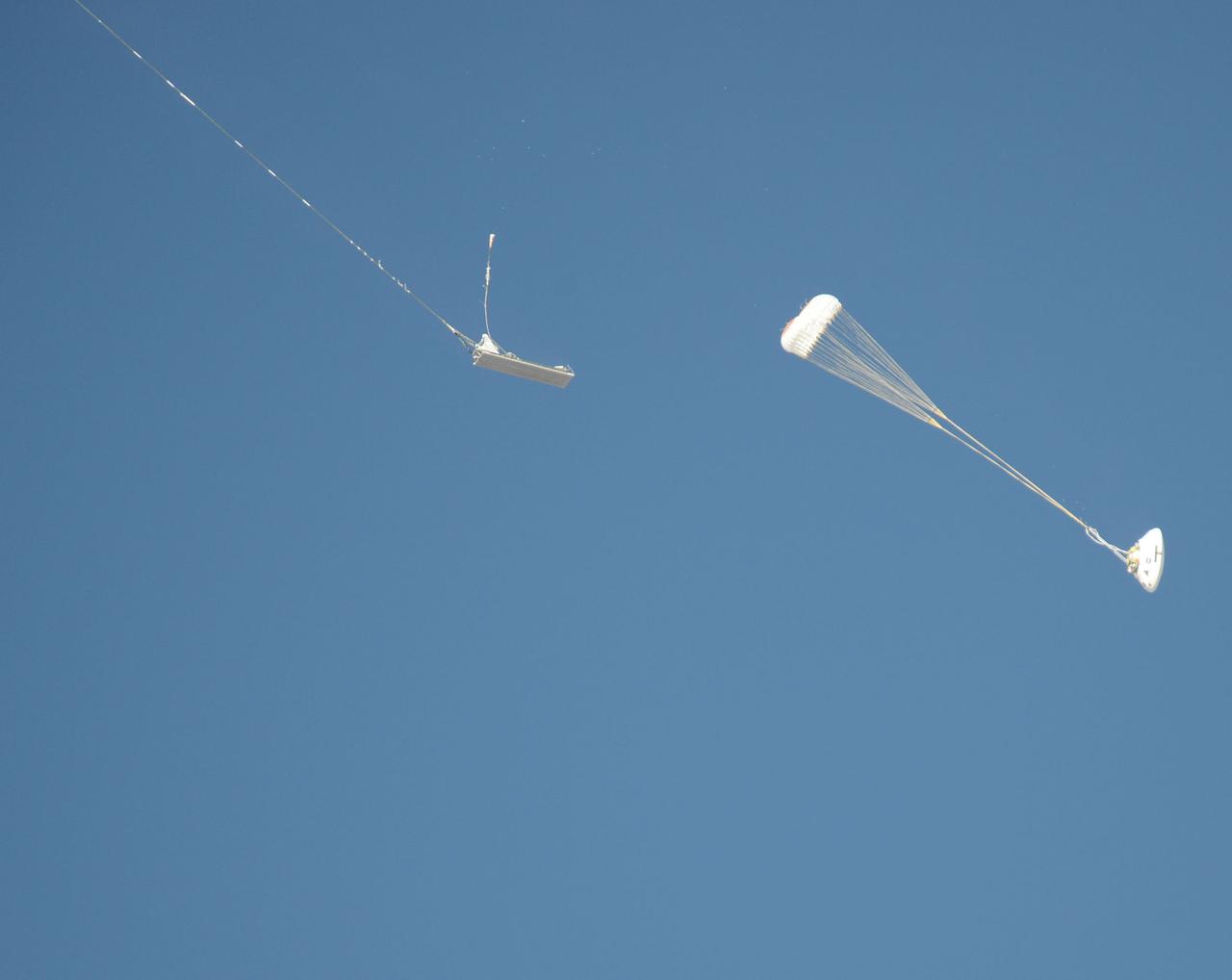
An Orion parachute test enters a new phase following separation from a platform.
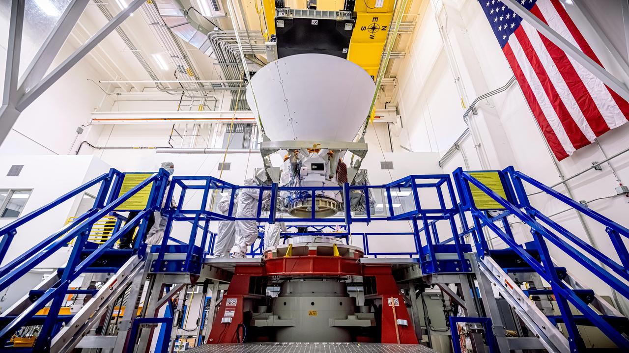
NASA's SPHEREx observatory is lifted and installed onto a vibration table in the Z-axis configuration at BAE Systems in Boulder, Colorado, in August 2024. In this test, the spacecraft is subjected to vibrations in all three axes separately. The test was successfully completed Aug. 16, 2024. Short for Spectro-Photometer for the History of the Universe, Epoch of Reionization and Ices Explorer, SPHEREx will create a map of the cosmos like no other. Using a technique called spectroscopy to image the entire sky in 102 wavelengths of infrared light, SPHEREx will gather information about the composition of and distance to millions of galaxies and stars. With this map, scientists will study what happened in the first fraction of a second after the big bang, how galaxies formed and evolved, and the origins of water in planetary systems in our galaxy. https://photojournal.jpl.nasa.gov/catalog/PIA26539
Ariane V Horizontal Separation System 3 (HSS3) Payload Fairing Separation Pre and Post Test Photo Documentation Inside Space Power Facility (SPF)
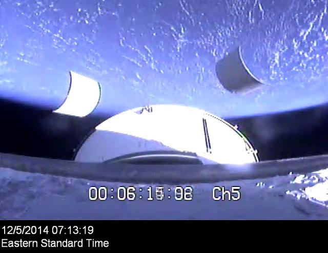
The service module panels separate during Orion's first flight test, Exploration Flight Test-1 (EFT-1), on December 5, 2014.

The crew module separates from service module on Orion's first flight test, Exploration Flight Test-1 (EFT-1), on December 5, 2014.
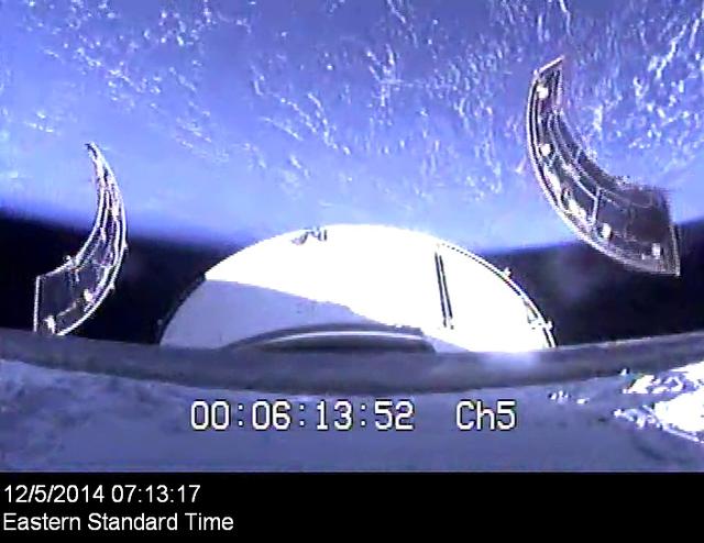
The service module panels separate during Orion's first flight test, Exploration Flight Test-1 (EFT-1), on December 5, 2014.
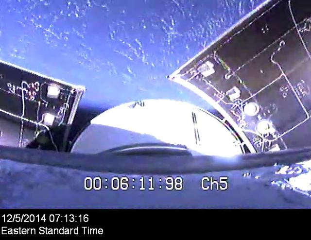
Orion's service module panels separate on its first flight test, Exploration Flight Test-1 (EFT-1), on December 5, 2014.
Orion's launch abort system separates on its first flight test, Exploration Flight Test-1 (EFT-1), on December 5, 2014.
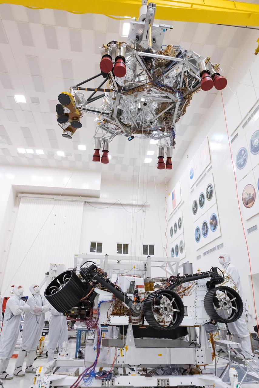
In this picture from Sept. 28, 2019, engineers and technicians working on the Mars 2020 spacecraft at NASA's Jet Propulsion Laboratory in Pasadena, California, look on as a crane lifts the rocket-powered descent stage away from the rover after a test. https://photojournal.jpl.nasa.gov/catalog/PIA23466
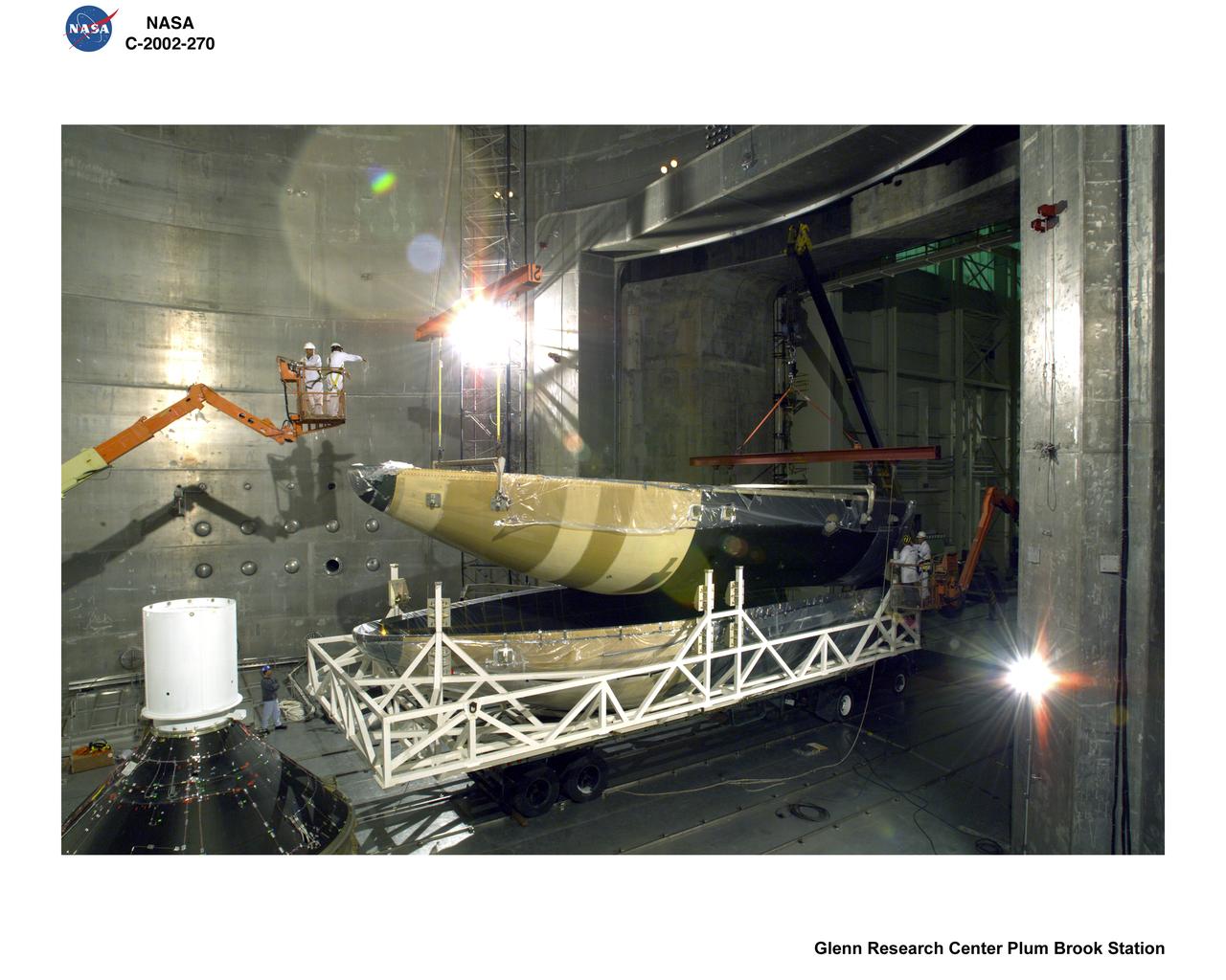
BOEING DELTA 4 SHROUD SEPARATION TEST IN SPACE POWER FACILITY AT NASA PLUM BROOK STATION
BOEING DELTA 4 SHROUD SEPARATION TEST IN SPACE POWER FACILITY AT NASA PLUM BROOK STATION
BOEING DELTA 4 SHROUD SEPARATION TEST IN SPACE POWER FACILITY AT NASA PLUM BROOK STATION
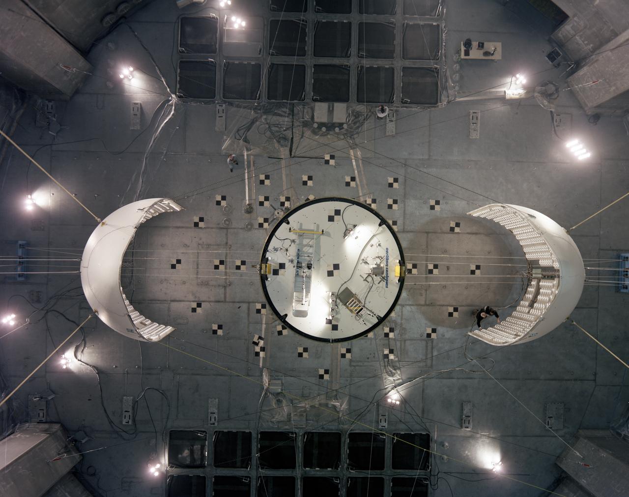
Top down photograph showing separation of the Ariane V fairing after testing in the vacuum chamber at SEC
BOEING DELTA 4 SHROUD SEPARATION TEST IN SPACE POWER FACILITY AT NASA PLUM BROOK STATION
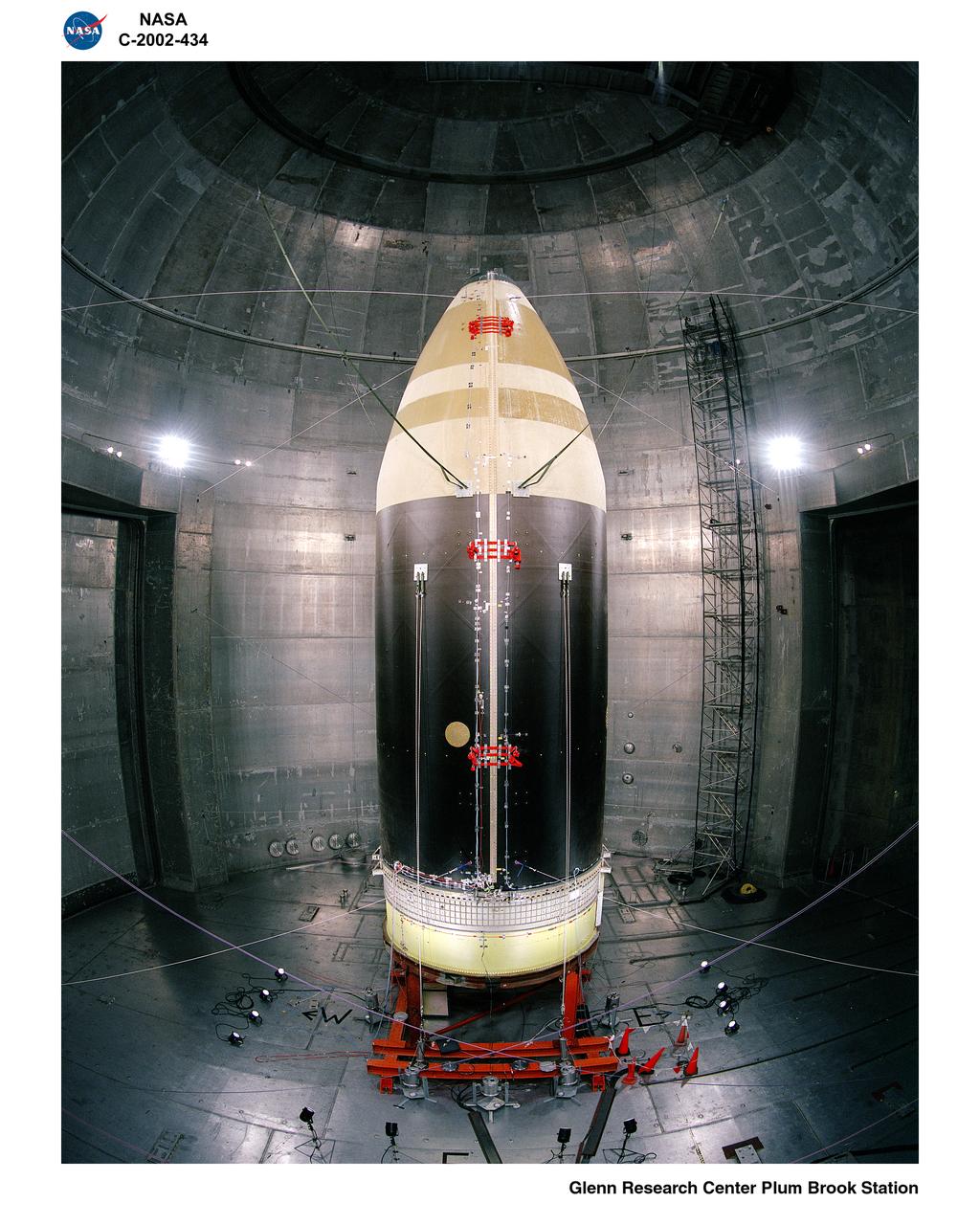
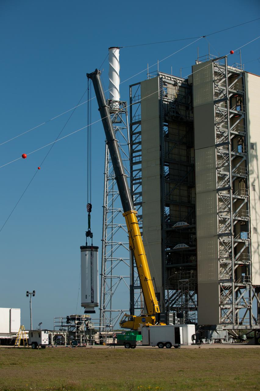
ATLAS V PAYLOAD FARING IN NASA PLUM BROOK STATION SPACE POWER FACILITY PRIOR TO SEPARATION TEST
BOEING DELTA 4 SHROUD SEPARATION TEST IN SPACE POWER FACILITY AT NASA PLUM BROOK STATION
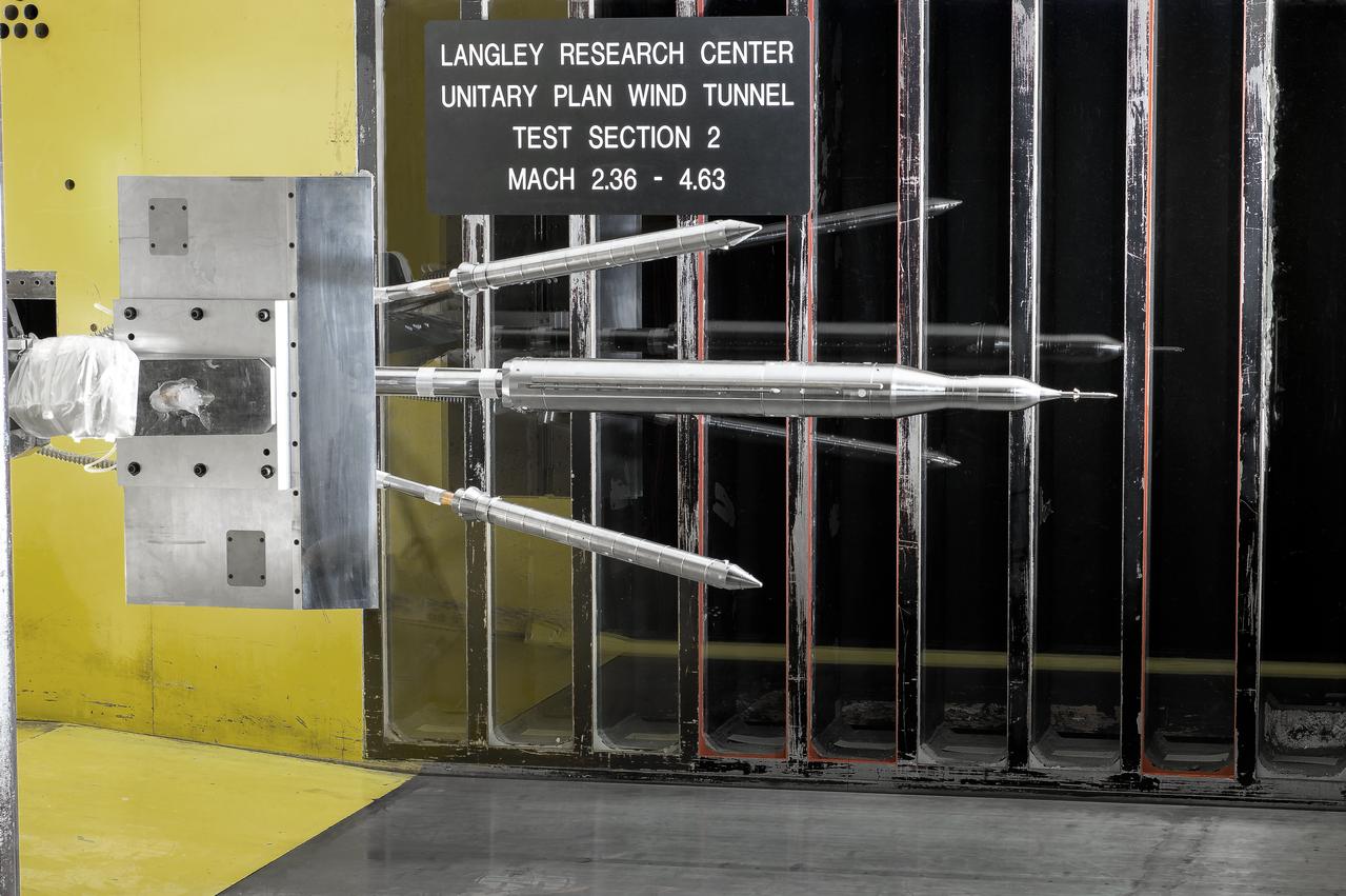
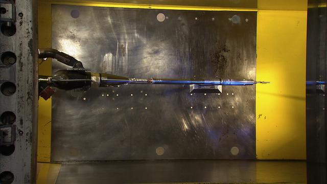
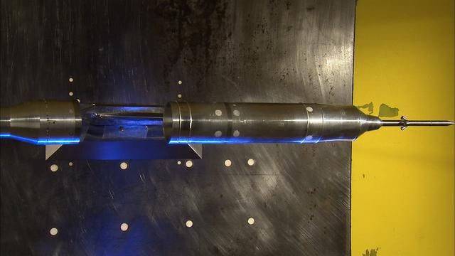
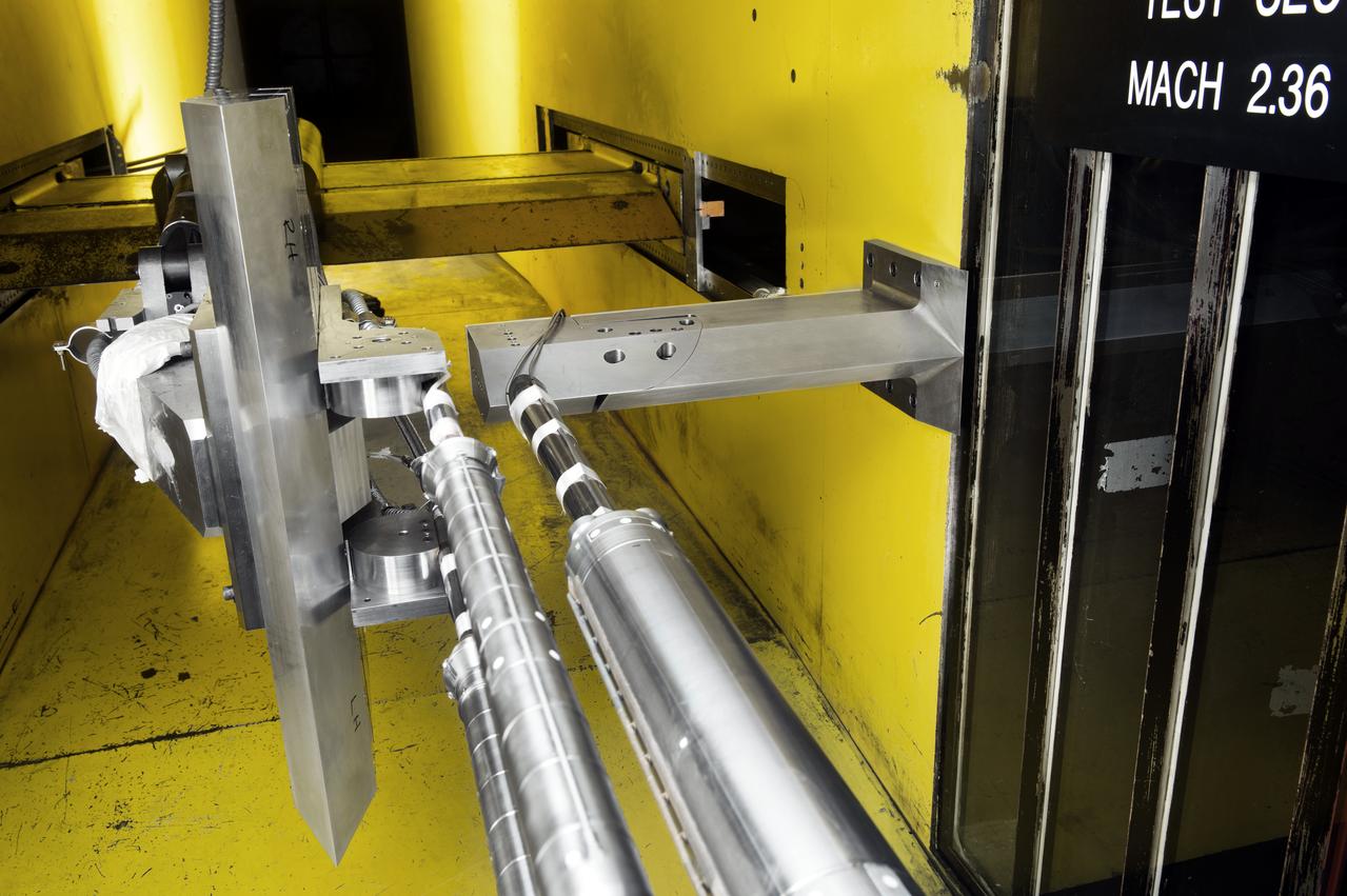
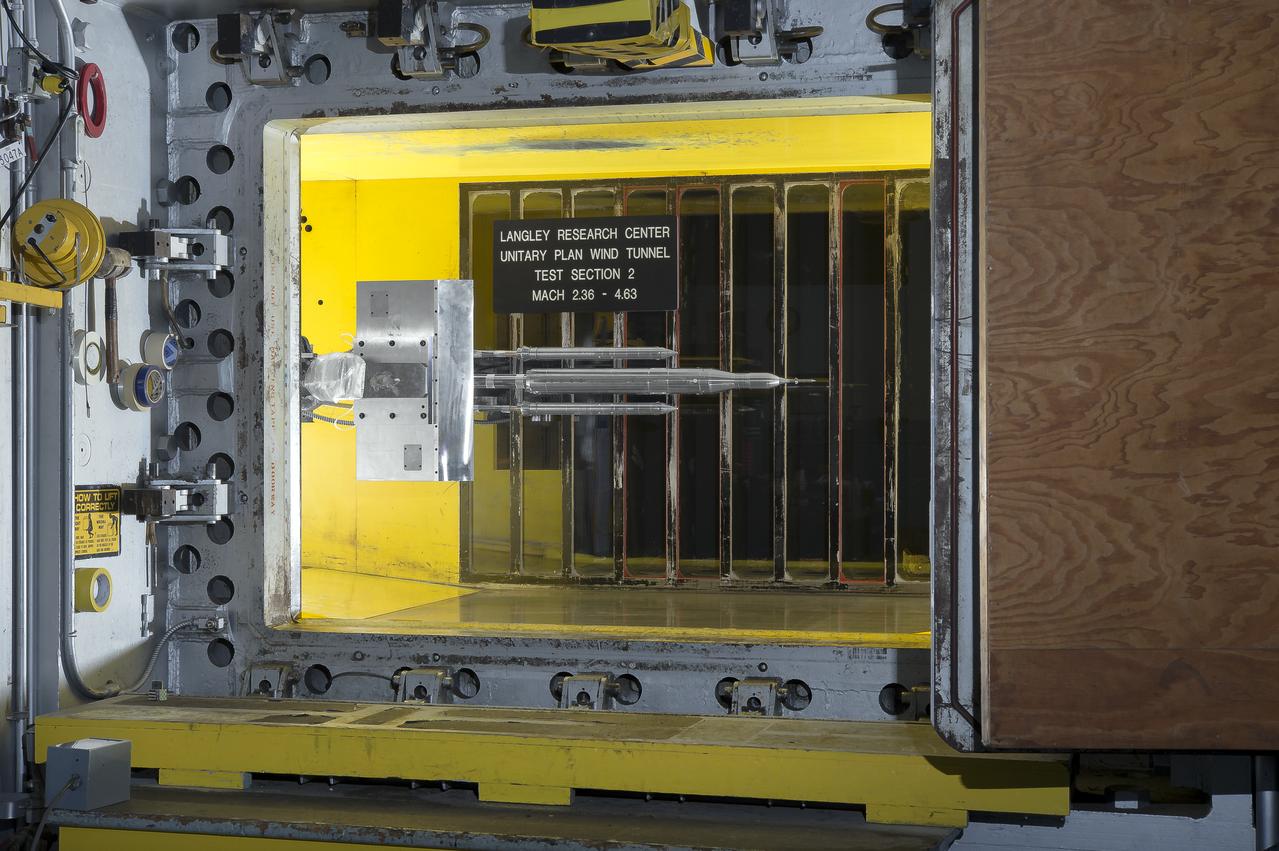
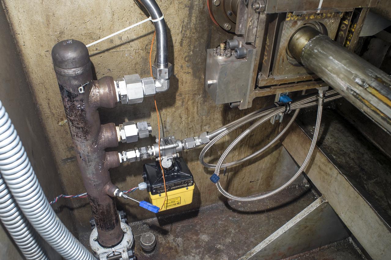
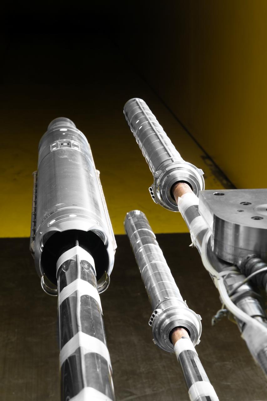
Stage Separation Test of the Space Launch System(SLS) in the Langley Unitary Plan Wind Tunnel (UPWT). The model used High Pressure air blown through the solid rocket boosters. (SRB) to simulate the booster separation motors (BSM) firing.
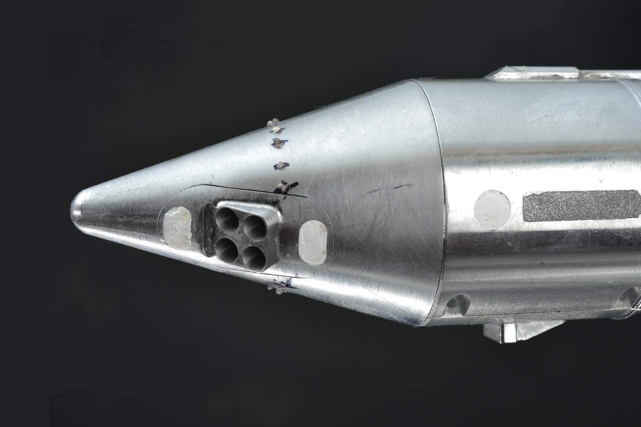
Stage Separation Test of the Space Launch System(SLS) in the Langley Unitary Plan Wind Tunnel (UPWT). The model used High Pressure air blown through the solid rocket boosters. (SRB) to simulate the booster separation motors (BSM) firing.
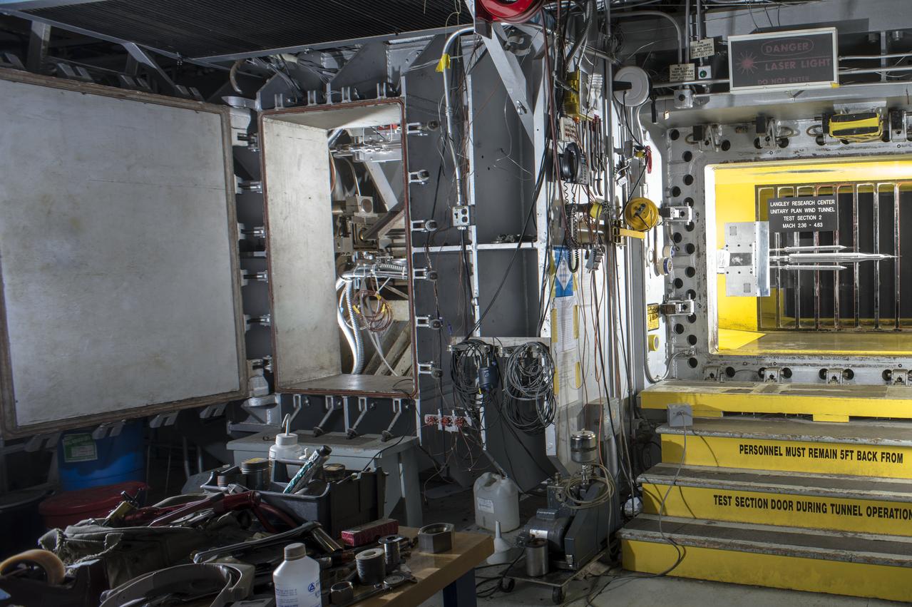
Stage Separation Test of the Space Launch System(SLS) in the Langley Unitary Plan Wind Tunnel (UPWT). The model used High Pressure air blown through the solid rocket boosters. (SRB) to simulate the booster separation motors (BSM) firing.
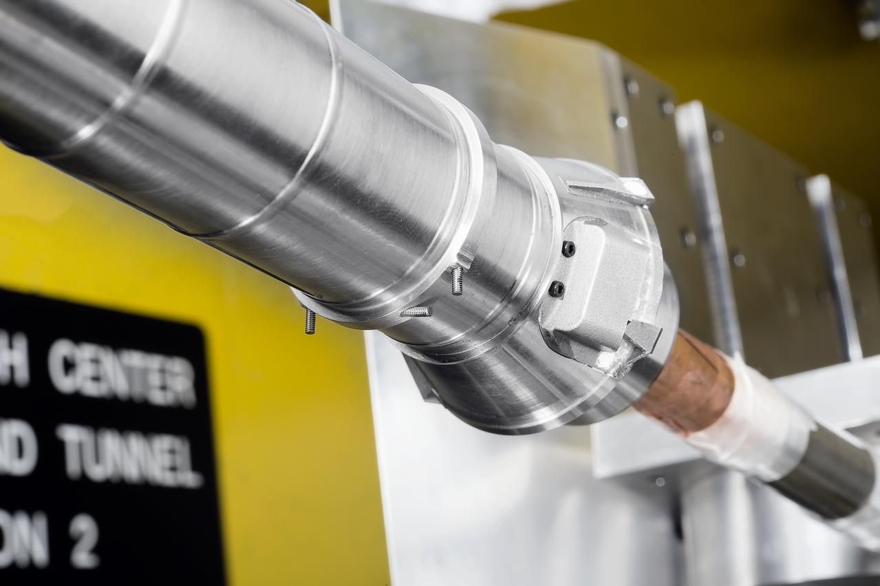
Stage Separation Test of the Space Launch System(SLS) in the Langley Unitary Plan Wind Tunnel (UPWT). The model used High Pressure air blown through the solid rocket boosters. (SRB) to simulate the booster separation motors (BSM) firing.
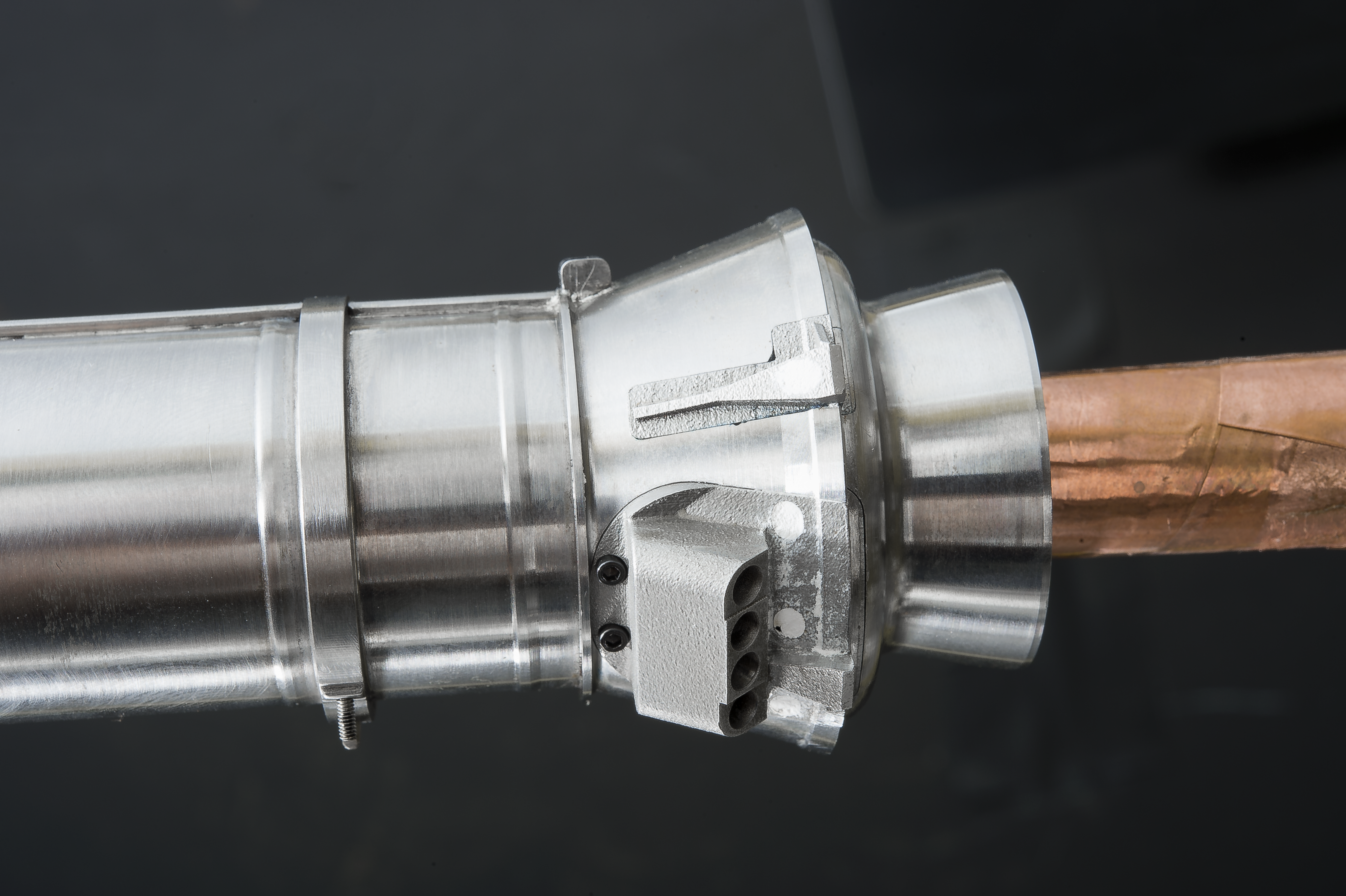
Stage Separation Test of the Space Launch System(SLS) in the Langley Unitary Plan Wind Tunnel (UPWT). The model used High Pressure air blown through the solid rocket boosters. (SRB) to simulate the booster separation motors (BSM) firing.
Stage Separation Test of the Space Launch System(SLS) in the Langley Unitary Plan Wind Tunnel (UPWT). The model used High Pressure air blown through the solid rocket boosters. (SRB) to simulate the booster separation motors (BSM) firing.
Stage Separation Test of the Space Launch System(SLS) in the Langley Unitary Plan Wind Tunnel (UPWT). The model used High Pressure air blown through the solid rocket boosters. (SRB) to simulate the booster separation motors (BSM) firing.
Stage Separation Test of the Space Launch System(SLS) in the Langley Unitary Plan Wind Tunnel (UPWT). The model used High Pressure air blown through the solid rocket boosters. (SRB) to simulate the booster separation motors (BSM) firing.
Stage Separation Test of the Space Launch System(SLS) in the Langley Unitary Plan Wind Tunnel (UPWT). The model used High Pressure air blown through the solid rocket boosters. (SRB) to simulate the booster separation motors (BSM) firing.

Stage Separation Test of the Space Launch System(SLS) in the Langley Unitary Plan Wind Tunnel (UPWT). The model used High Pressure air blown through the solid rocket boosters. (SRB) to simulate the booster separation motors (BSM) firing.
Stage Separation Test of the Space Launch System(SLS) in the Langley Unitary Plan Wind Tunnel (UPWT). The model used High Pressure air blown through the solid rocket boosters. (SRB) to simulate the booster separation motors (BSM) firing.
Stage Separation Test of the Space Launch System(SLS) in the Langley Unitary Plan Wind Tunnel (UPWT). The model used High Pressure air blown through the solid rocket boosters. (SRB) to simulate the booster separation motors (BSM) firing.
Stage Separation Test of the Space Launch System(SLS) in the Langley Unitary Plan Wind Tunnel (UPWT). The model used High Pressure air blown through the solid rocket boosters. (SRB) to simulate the booster separation motors (BSM) firing.

Stage Separation Test of the Space Launch System(SLS) in the Langley Unitary Plan Wind Tunnel (UPWT). The model used High Pressure air blown through the solid rocket boosters. (SRB) to simulate the booster separation motors (BSM) firing.
Stage Separation Test of the Space Launch System(SLS) in the Langley Unitary Plan Wind Tunnel (UPWT). The model used High Pressure air blown through the solid rocket boosters. (SRB) to simulate the booster separation motors (BSM) firing.
Stage Separation Test of the Space Launch System(SLS) in the Langley Unitary Plan Wind Tunnel (UPWT). The model used High Pressure air blown through the solid rocket boosters. (SRB) to simulate the booster separation motors (BSM) firing.
Stage Separation Test of the Space Launch System(SLS) in the Langley Unitary Plan Wind Tunnel (UPWT). The model used High Pressure air blown through the solid rocket boosters. (SRB) to simulate the booster separation motors (BSM) firing.
Stage Separation Test of the Space Launch System(SLS) in the Langley Unitary Plan Wind Tunnel (UPWT). The model used High Pressure air blown through the solid rocket boosters. (SRB) to simulate the booster separation motors (BSM) firing.
Stage Separation Test of the Space Launch System(SLS) in the Langley Unitary Plan Wind Tunnel (UPWT). The model used High Pressure air blown through the solid rocket boosters. (SRB) to simulate the booster separation motors (BSM) firing.
Stage Separation Test of the Space Launch System(SLS) in the Langley Unitary Plan Wind Tunnel (UPWT). The model used High Pressure air blown through the solid rocket boosters. (SRB) to simulate the booster separation motors (BSM) firing.
Stage Separation Test of the Space Launch System(SLS) in the Langley Unitary Plan Wind Tunnel (UPWT). The model used High Pressure air blown through the solid rocket boosters. (SRB) to simulate the booster separation motors (BSM) firing.
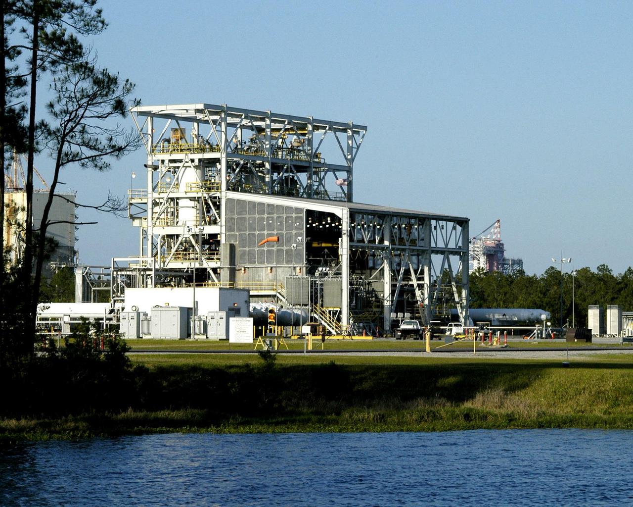
The E Test Complex is SSC's versatile, three-stand complex that includes seven separate test cells capable of testing that involves ultra high-pressure gases and cryogenic fluids.
S70-41983 (June 1970) --- Second photograph in sequence of three of panel separation test at Langley Research Center. The test was part of the Apollo 13 post flight investigation of the Service Module explosion incident. Photo credit: NASA
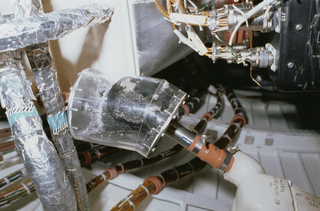
STS040-34-001 (5-14 June 1991) --- This 35mm scene shows a close-up of a prototype filter designed to remove contamination from air and water, before it flows into the Orbiter's humidity separators. This experiment is part of Development Test Objective (DTO) 647, Water Separator Filter Performance Evaluation. Astronauts Bryan D. O'Connor, mission commander, and Sidney M. Gutierrez, pilot, carried out the test and down linked television to the ground for engineering analysis.
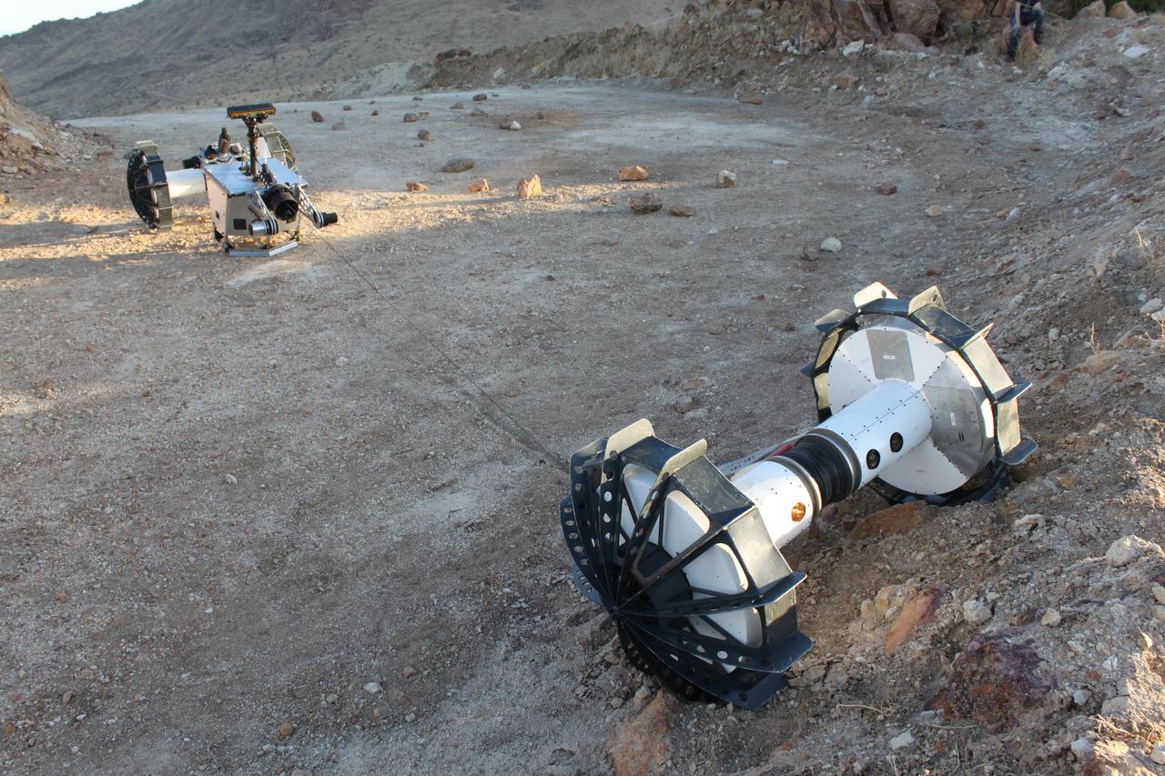
During a field test in the Mojave Desert, the DuAxel robot separates into two single-axled robots so that one can rappel down a slope too steep for conventional rovers. The tether connecting both Axels not only allows the one robot to descend the slope while the other remains anchored in place, it also provides power and a means of communication with the anchoring robot above. The DuAxel project is a technology demonstration being developed by roboticists at NASA's Jet Propulsion Laboratory in Southern California to see how this unconventional rover might fill a niche in the exploration the Moon, Mars, and beyond. https://photojournal.jpl.nasa.gov/catalog/PIA24109
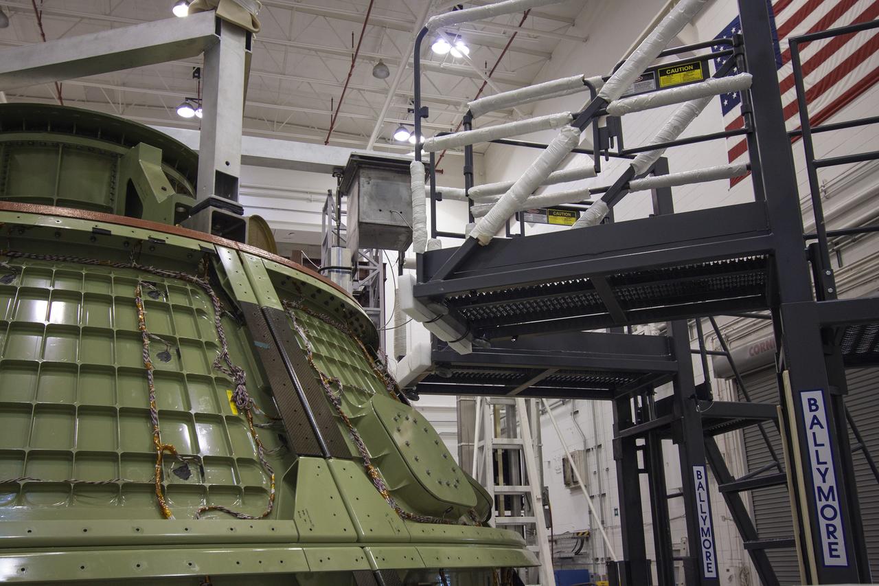
A heat shield is used during separation test activities with Boeing's Starliner structural test article. The test article is undergoing rigorous qualification testing at the company's Huntington Beach Facility in California. Boeing’s CST-100 Starliner will launch on the Atlas V rocket to the International Space Station as part of NASA’s Commercial Crew Program.
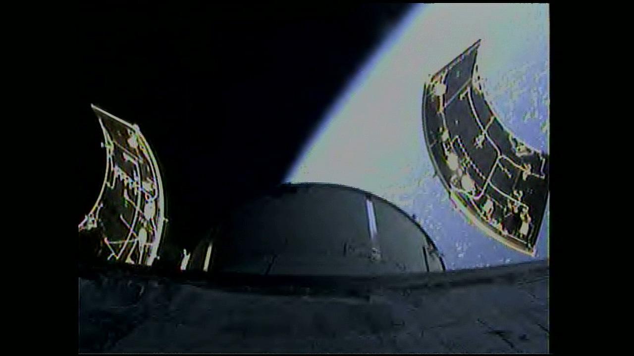
An onboard camera captures separation of the three 13 by 14-foot Orion service module fairings following lift off the Delta IV Heavy rocket from Space Launch Complex 37 at Cape Canaveral Air Force Station in Florida on Dec. 5, 2014. Exploration Flight Test-1 (EFT-1) also will validate systems such as Orion’s parachutes, avionics and attitude control, and demonstrate major separation events such as the launch abort system jettison and the service module fairing separation. Part of Batch image transfer from Flickr.
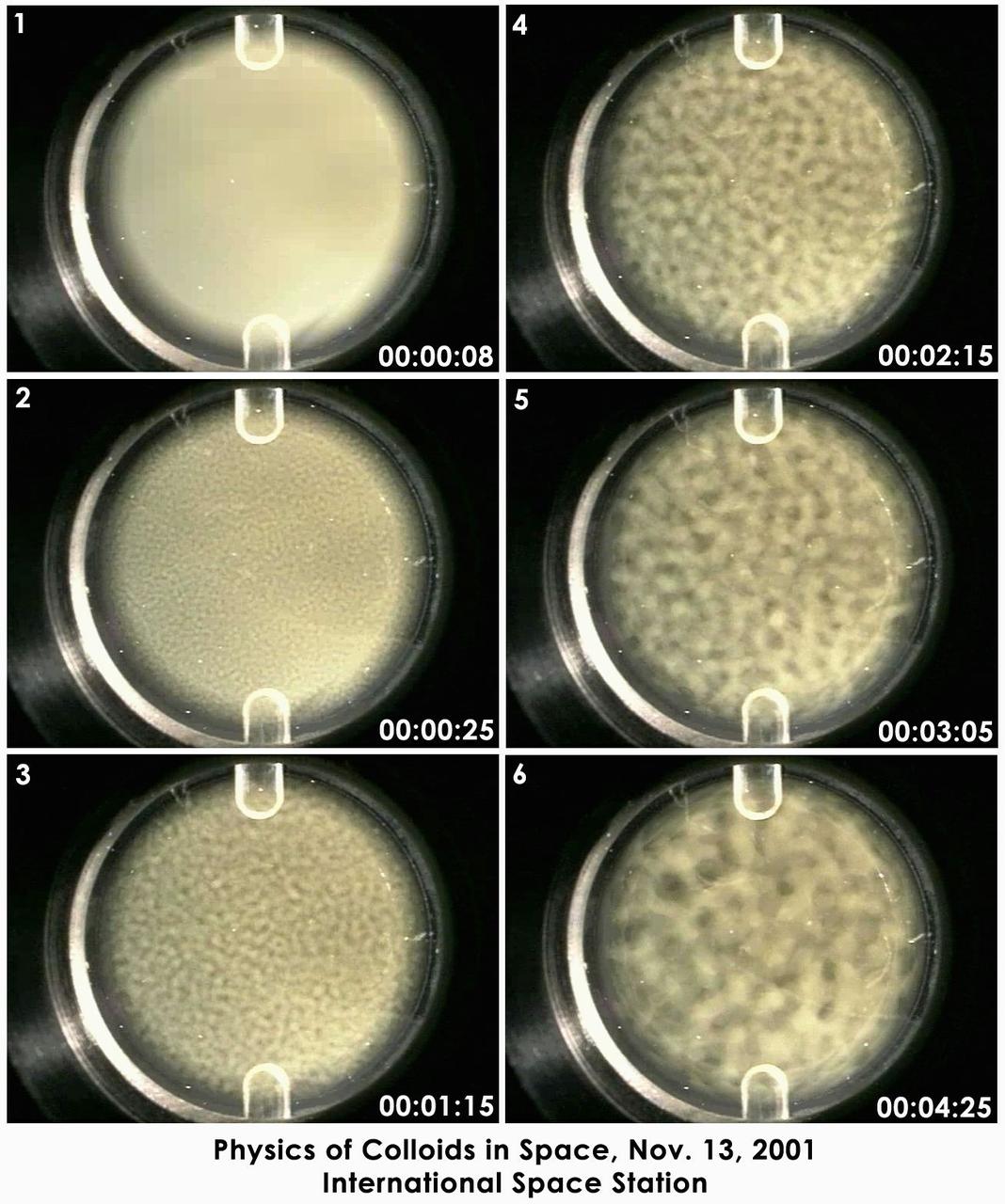
Still photographs taken over 16 hours on Nov. 13, 2001, on the International Space Station have been condensed into a few seconds to show the de-mixing -- or phase separation -- process studied by the Experiment on Physics of Colloids in Space. Commanded from the ground, dozens of similar tests have been conducted since the experiment arrived on ISS in 2000. The sample is a mix of polymethylmethacrylate (PMMA or acrylic) colloids, polystyrene polymers and solvents. The circular area is 2 cm (0.8 in.) in diameter. The phase separation process occurs spontaneously after the sample is mechanically mixed. The evolving lighter regions are rich in colloid and have the structure of a liquid. The dark regions are poor in colloids and have the structure of a gas. This behavior carnot be observed on Earth because gravity causes the particles to fall out of solution faster than the phase separation can occur. While similar to a gas-liquid phase transition, the growth rate observed in this test is different from any atomic gas-liquid or liquid-liquid phase transition ever measured experimentally. Ultimately, the sample separates into colloid-poor and colloid-rich areas, just as oil and vinegar separate. The fundamental science of de-mixing in this colloid-polymer sample is the same found in the annealing of metal alloys and plastic polymer blends. Improving the understanding of this process may lead to improving processing of these materials on Earth.
CAPE CANAVERAL, Fla. -- The Orion ground test vehicle sits on a test stand in the Launch Equipment Test Facility at NASA’s Kennedy Space Center in Florida while engineers and technicians prepare it for a pyrotechnic bolt test. Lockheed Martin performed tests over a series of days on the explosive bolts that separate Orion from the launch abort system. Data was collected on the effect of shock waves on Orion during the explosive bolt separation. Orion is the exploration spacecraft designed to carry crews to space beyond low Earth orbit. It will provide emergency abort capability, sustain the crew during the space travel and provide safe re-entry from deep space return velocities. The first unpiloted test flight of the Orion is scheduled to launch in 2014 atop a Delta IV rocket and in 2017 on a Space Launch System rocket. For more information, visit http://www.nasa.gov/orion. Photo credit: NASA/Jim Grossmann
CAPE KENNEDY, Fla. -- The Orion ground test vehicle sits on a test stand in the Launch Equipment Test Facility at NASA’s Kennedy Space Center in Florida while engineers and technicians prepare it for a pyrotechnic bolt test. Lockheed Martin performed tests over a series of days on the explosive bolts that separate Orion from the launch abort system. Data was collected on the effect of shock waves on Orion during the explosive bolt separation. Orion is the exploration spacecraft designed to carry crews to space beyond low Earth orbit. It will provide emergency abort capability, sustain the crew during the space travel and provide safe re-entry from deep space return velocities. The first unpiloted test flight of the Orion is scheduled to launch in 2014 atop a Delta IV rocket and in 2017 on a Space Launch System rocket. For more information, visit http://www.nasa.gov/orion. Photo credit: NASA/Kim Shiflett
CAPE KENNEDY, Fla. -- Inside the Launch Equipment Test Facility at NASA’s Kennedy Space in Florida, the Orion ground test vehicle has been transferred to a test stand and prepared for a pyrotechnic bolt test. Lockheed Martin performed tests over a series of days on the explosive bolts that separate Orion from the launch abort system. Data was collected on the effect of shock waves on Orion during the explosive bolt separation. Orion is the exploration spacecraft designed to carry crews to space beyond low Earth orbit. It will provide emergency abort capability, sustain the crew during the space travel and provide safe re-entry from deep space return velocities. The first unpiloted test flight of the Orion is scheduled to launch in 2014 atop a Delta IV rocket and in 2017 on a Space Launch System rocket. For more information, visit http://www.nasa.gov/orion. Photo credit: NASA/Kim Shiflett
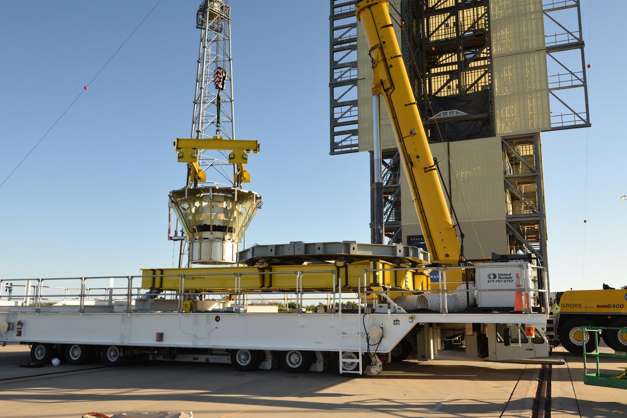
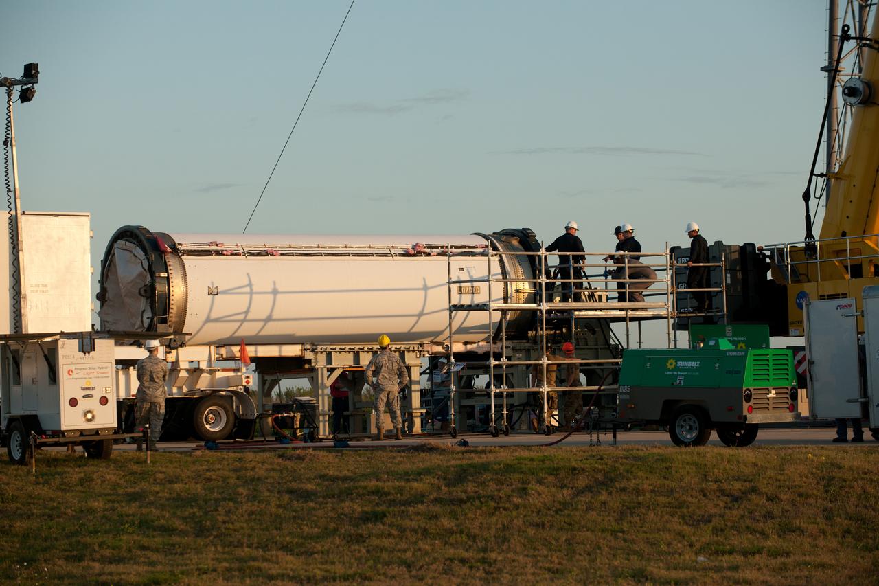
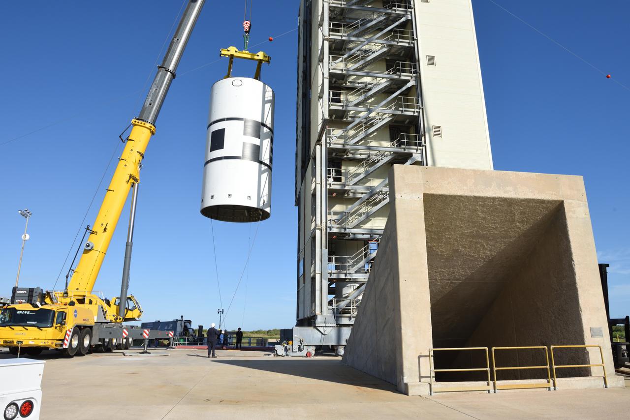
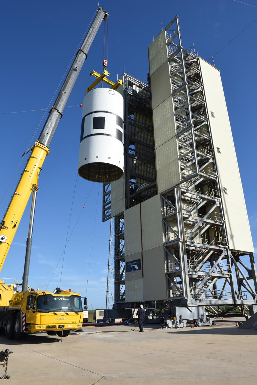
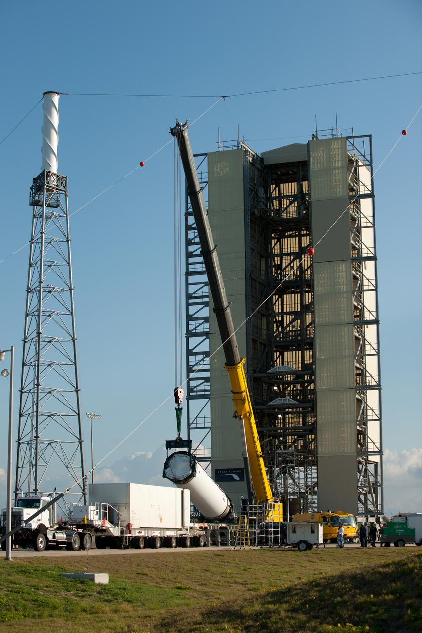
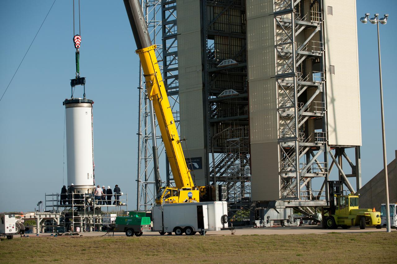
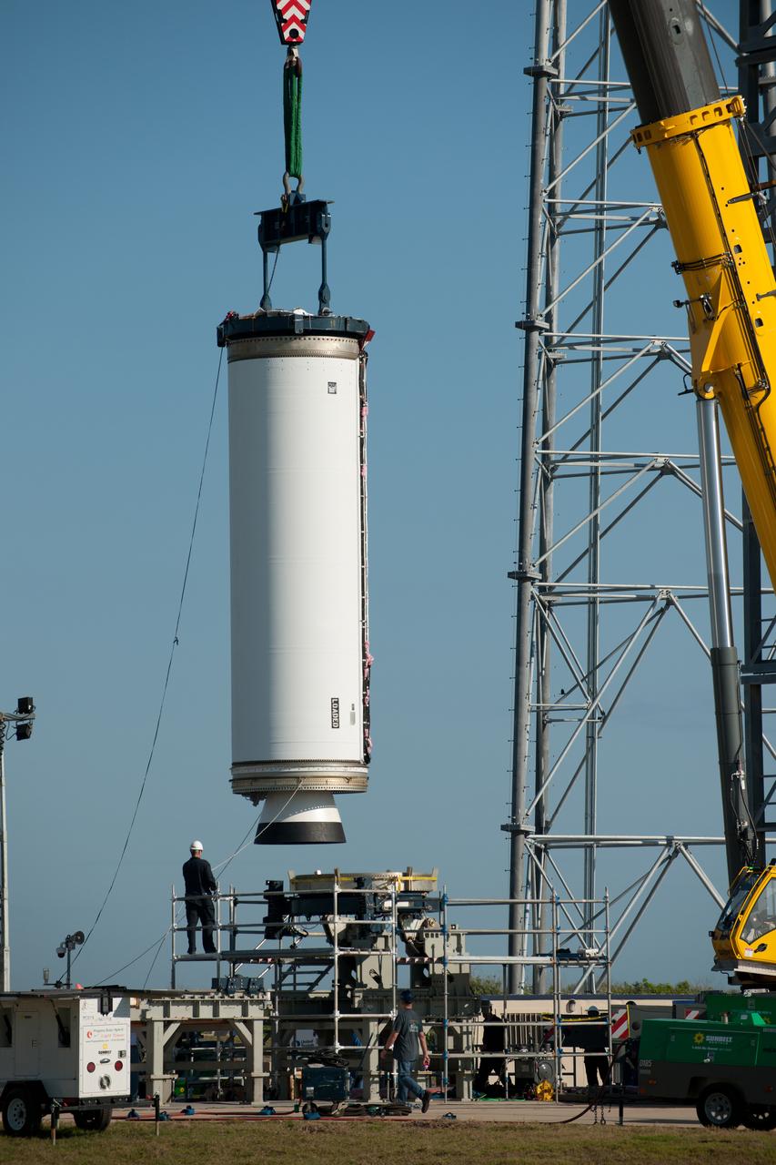
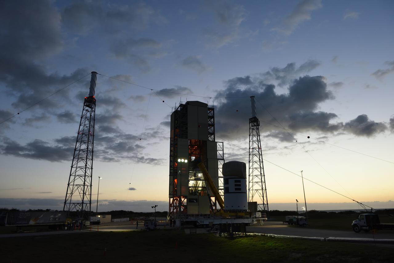
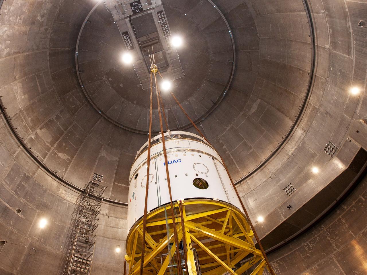
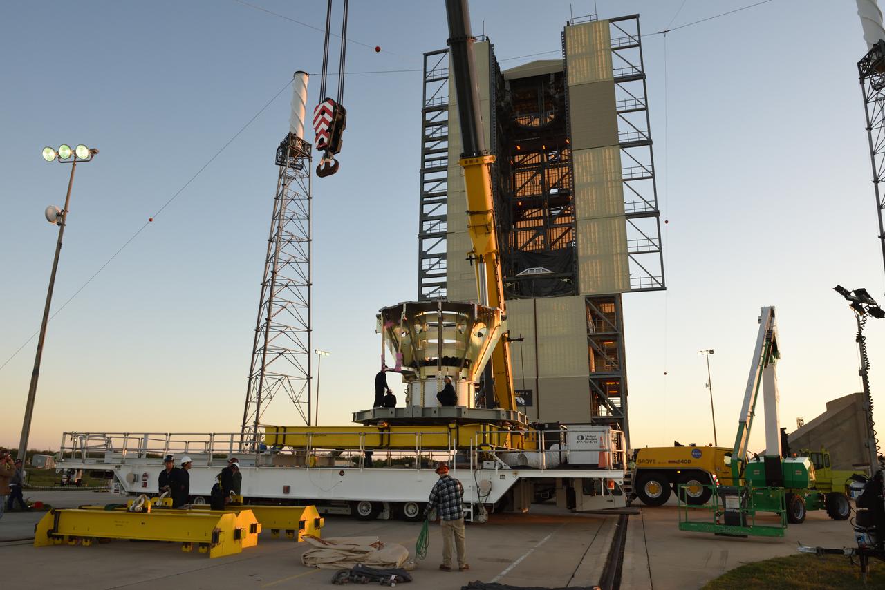
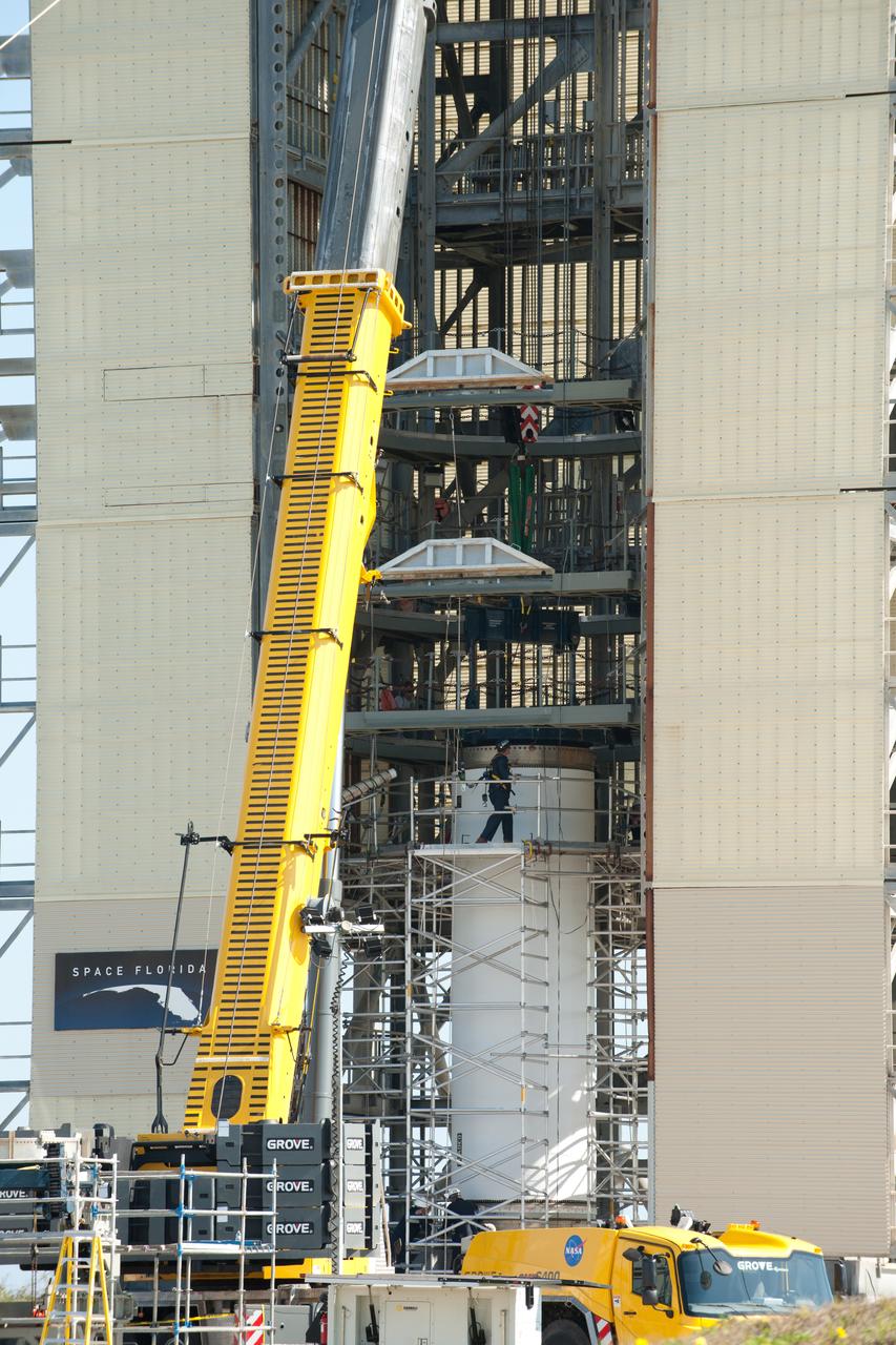
The Abort Test Booster, the rocket which will propel Orion's Launch Abort System and crew module / separation ring during the Ascent Abort -2 (AA-2) flight test, is stacked at the launch pad at Cape Canaveral Air Force Station in Florida on April 12, 2019.
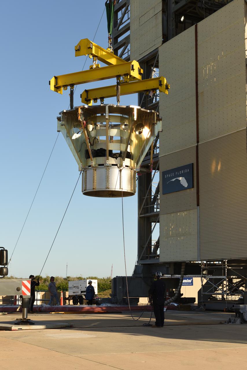
The Abort Test Booster, the rocket which will propel Orion's Launch Abort System and crew module / separation ring during the Ascent Abort -2 (AA-2) flight test, is stacked at the launch pad at Cape Canaveral Air Force Station in Florida on April 12, 2019.
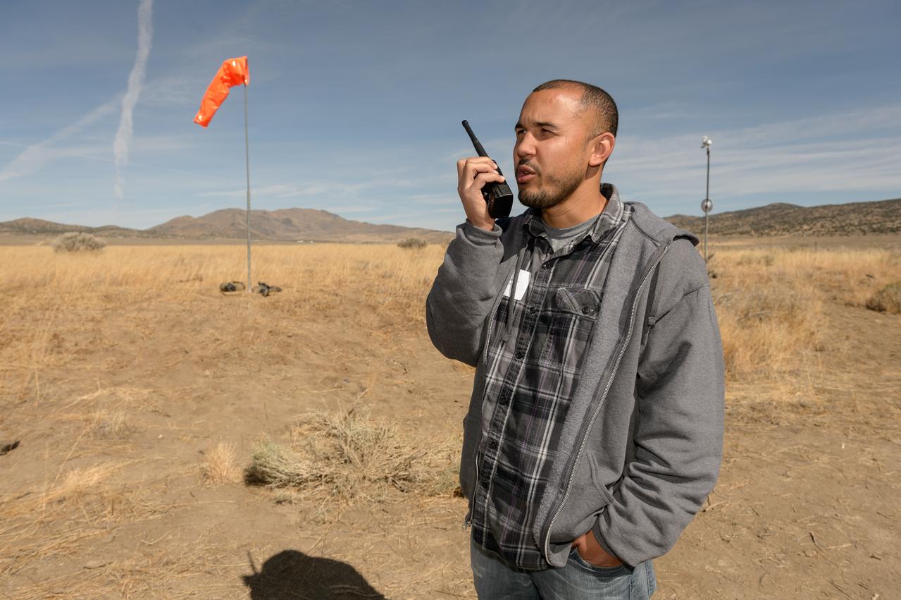
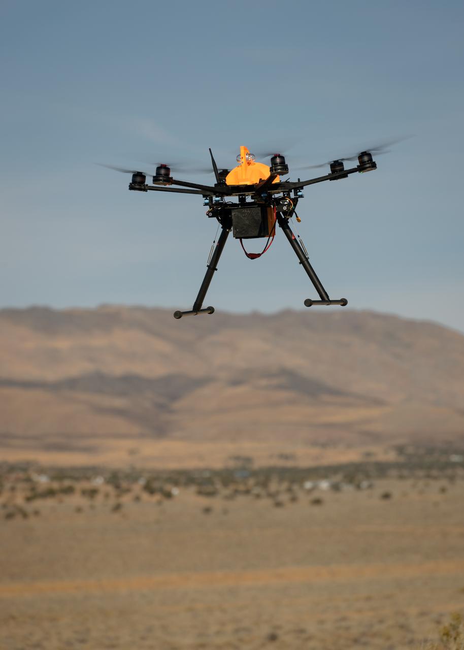
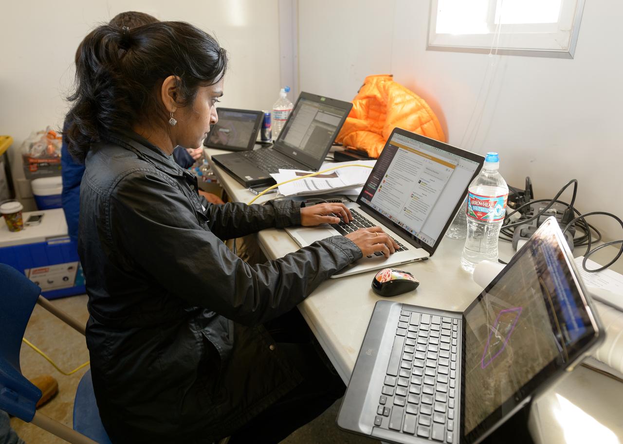
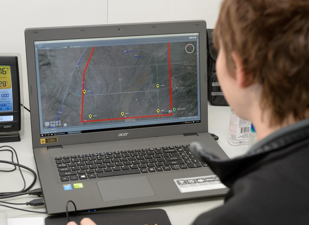
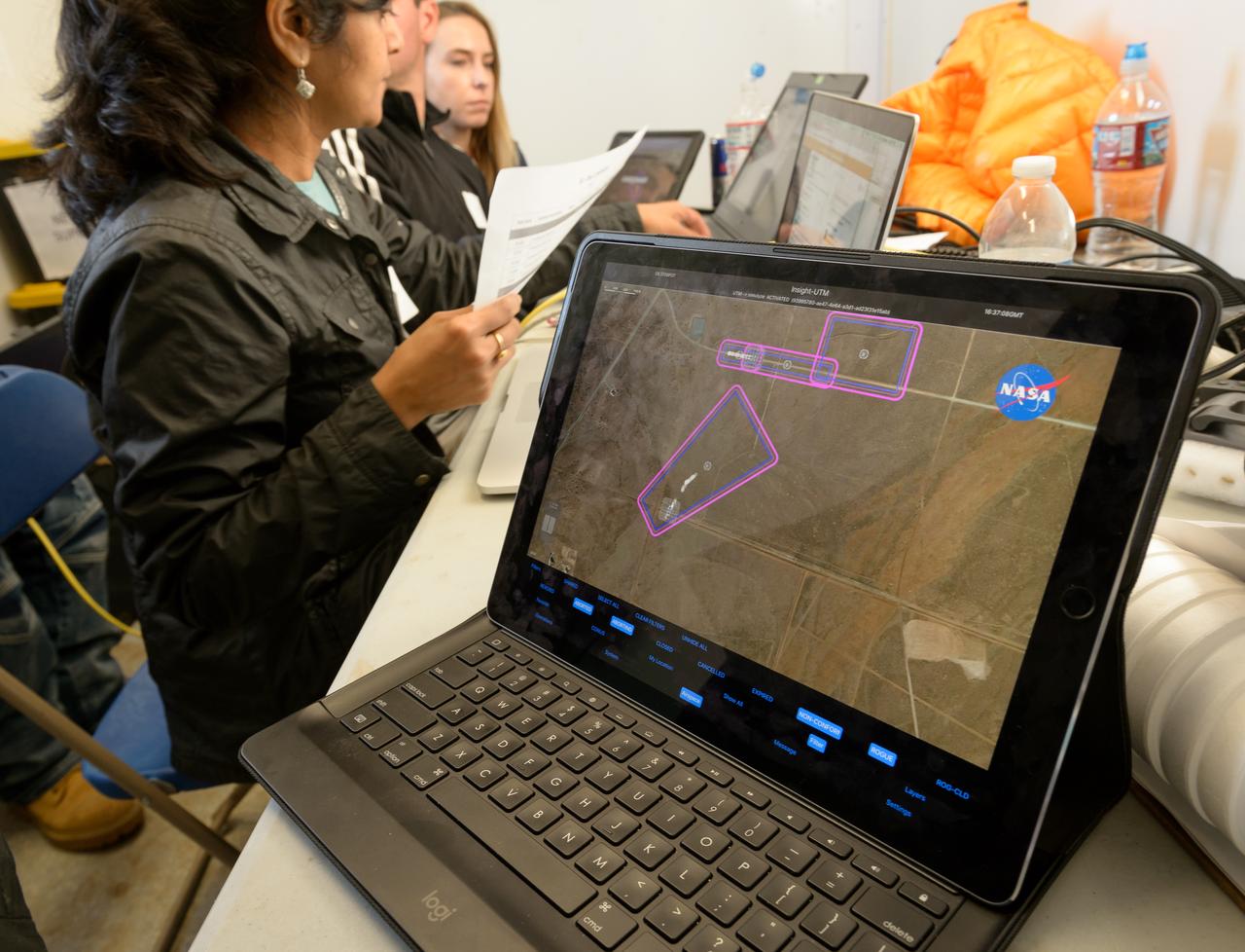
Test of Unmanned Aircraft Systems Traffic Management (UTM) technical capability Level 2 (TCL2) at Reno-Stead Airport, Nevada. During the test, five drones simultaneously crossed paths, separated by altitude. Two drones flew beyond visual line-of-sight and three flew within line-of-sight of their operators.
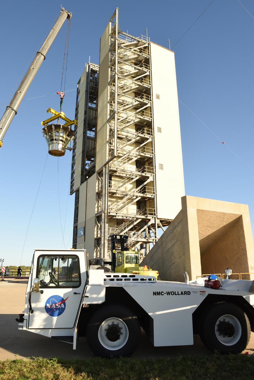
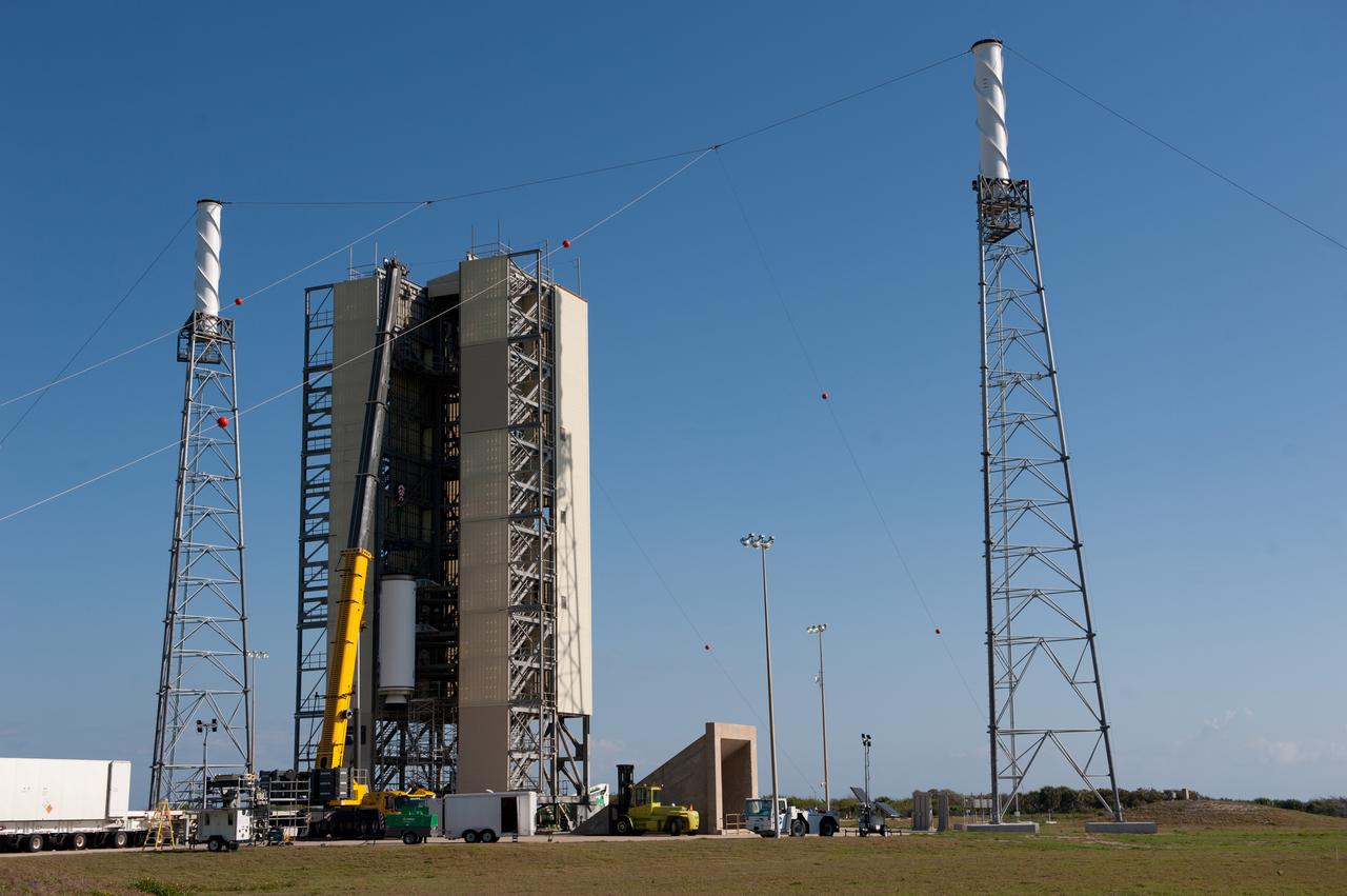
The Abort Test Booster, the rocket which will propel Orion's Launch Abort System and crew module / separation ring during the Ascent Abort -2 (AA-2) flight test, is stacked at the launch pad at Cape Canaveral Air Force Station in Florida on April 12, 2019.
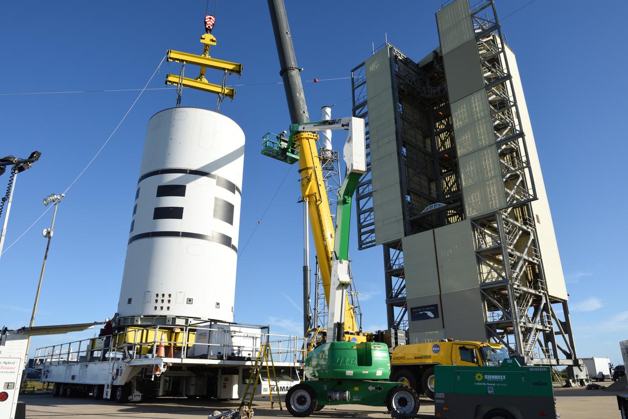
The Abort Test Booster, the rocket which will propel Orion's Launch Abort System and crew module / separation ring during the Ascent Abort -2 (AA-2) flight test, is stacked at the launch pad at Cape Canaveral Air Force Station in Florida on April 12, 2019.
Test of Unmanned Aircraft Systems Traffic Management (UTM) technical capability Level 2 (TCL2) at Reno-Stead Airport, Nevada. During the test, five drones simultaneously crossed paths, separated by altitude. Two drones flew beyond visual line-of-sight and three flew within line-of-sight of their operators.
Test of Unmanned Aircraft Systems Traffic Management (UTM) technical capability Level 2 (TCL2) at Reno-Stead Airport, Nevada. During the test, five drones simultaneously crossed paths, separated by altitude. Two drones flew beyond visual line-of-sight and three flew within line-of-sight of their operators.
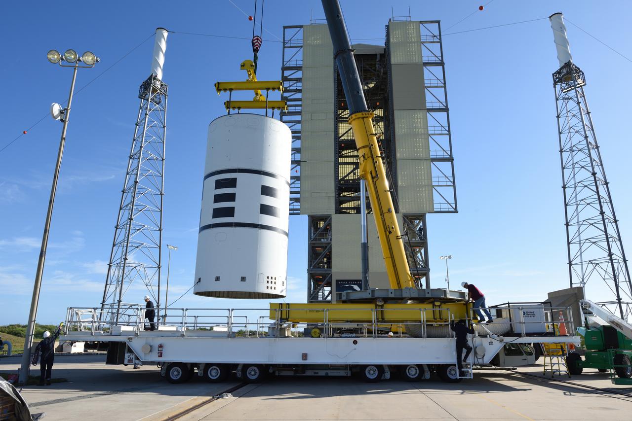
The Abort Test Booster, the rocket which will propel Orion's Launch Abort System and crew module / separation ring during the Ascent Abort -2 (AA-2) flight test, is stacked at the launch pad at Cape Canaveral Air Force Station in Florida on April 12, 2019.
The Abort Test Booster, the rocket which will propel Orion's Launch Abort System and crew module / separation ring during the Ascent Abort -2 (AA-2) flight test, is stacked at the launch pad at Cape Canaveral Air Force Station in Florida on April 12, 2019.
The Abort Test Booster, the rocket which will propel Orion's Launch Abort System and crew module / separation ring during the Ascent Abort -2 (AA-2) flight test, is stacked at the launch pad at Cape Canaveral Air Force Station in Florida on April 12, 2019.
The Abort Test Booster, the rocket which will propel Orion's Launch Abort System and crew module / separation ring during the Ascent Abort -2 (AA-2) flight test, is stacked at the launch pad at Cape Canaveral Air Force Station in Florida on April 12, 2019.
The Abort Test Booster, the rocket which will propel Orion's Launch Abort System and crew module / separation ring during the Ascent Abort -2 (AA-2) flight test, is stacked at the launch pad at Cape Canaveral Air Force Station in Florida on April 12, 2019.
The Abort Test Booster, the rocket which will propel Orion's Launch Abort System and crew module / separation ring during the Ascent Abort -2 (AA-2) flight test, is stacked at the launch pad at Cape Canaveral Air Force Station in Florida on April 12, 2019.
S70-41985 (15 June 1970) --- The third photograph in sequence of three showing panel separation test at Langley Research Center (LRC). The test was part of the Apollo 13 post flight investigation of the Service Module explosion incident. Photo credit: NASA
Test of Unmanned Aircraft Systems Traffic Management (UTM) technical capability Level 2 (TCL2) at Reno-Stead Airport, Nevada. During the test, five drones simultaneously crossed paths, separated by altitude. Two drones flew beyond visual line-of-sight and three flew within line-of-sight of their operators.
The Abort Test Booster, the rocket which will propel Orion's Launch Abort System and crew module / separation ring during the Ascent Abort -2 (AA-2) flight test, is stacked at the launch pad at Cape Canaveral Air Force Station in Florida on April 12, 2019.
The Abort Test Booster, the rocket which will propel Orion's Launch Abort System and crew module / separation ring during the Ascent Abort -2 (AA-2) flight test, is stacked at the launch pad at Cape Canaveral Air Force Station in Florida on April 12, 2019.

Test of Unmanned Aircraft Systems Traffic Management (UTM) technical capability Level 2 (TCL2) at Reno-Stead Airport, Nevada. During the test, five drones simultaneously crossed paths, separated by altitude. Two drones flew beyond visual line-of-sight and three flew within line-of-sight of their operators.

Test of Unmanned Aircraft Systems Traffic Management (UTM) technical capability Level 2 (TCL2) at Reno-Stead Airport, Nevada. During the test, five drones simultaneously crossed paths, separated by altitude. Two drones flew beyond visual line-of-sight and three flew within line-of-sight of their operators.
Test of Unmanned Aircraft Systems Traffic Management (UTM) technical capability Level 2 (TCL2) at Reno-Stead Airport, Nevada. During the test, five drones simultaneously crossed paths, separated by altitude. Two drones flew beyond visual line-of-sight and three flew within line-of-sight of their operators.
The Abort Test Booster, the rocket which will propel Orion's Launch Abort System and crew module / separation ring during the Ascent Abort -2 (AA-2) flight test, is stacked at the launch pad at Cape Canaveral Air Force Station in Florida on April 12, 2019.
The Abort Test Booster, the rocket which will propel Orion's Launch Abort System and crew module / separation ring during the Ascent Abort -2 (AA-2) flight test, is stacked at the launch pad at Cape Canaveral Air Force Station in Florida on April 12, 2019.
The Abort Test Booster, the rocket which will propel Orion's Launch Abort System and crew module / separation ring during the Ascent Abort -2 (AA-2) flight test, is stacked at the launch pad at Cape Canaveral Air Force Station in Florida on April 12, 2019.
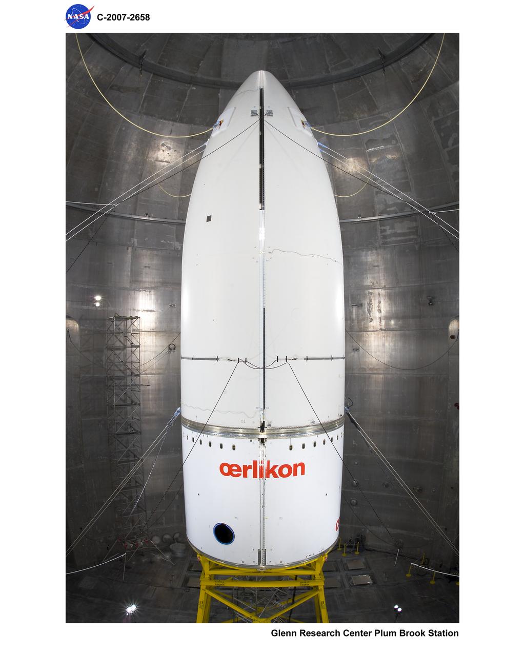
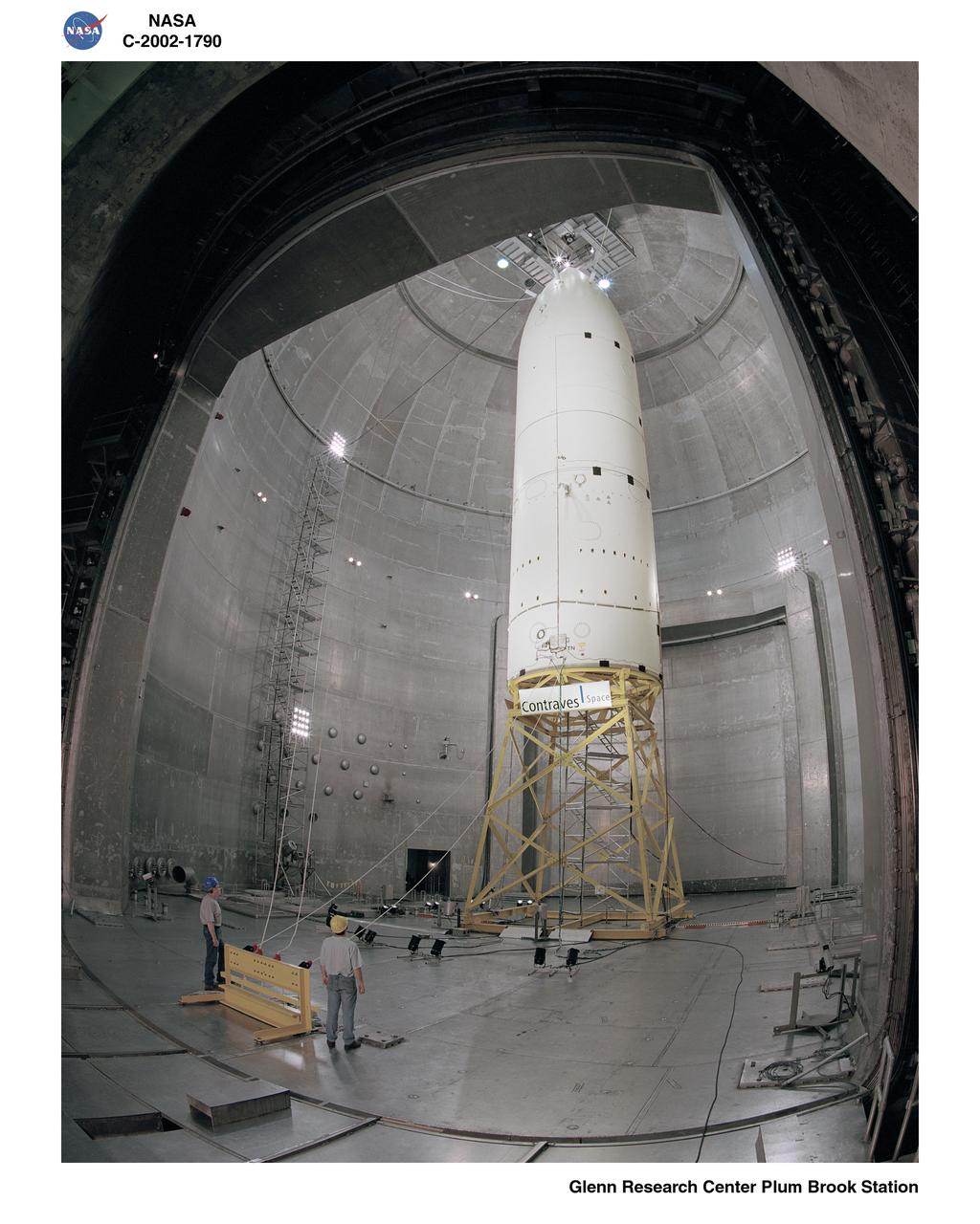
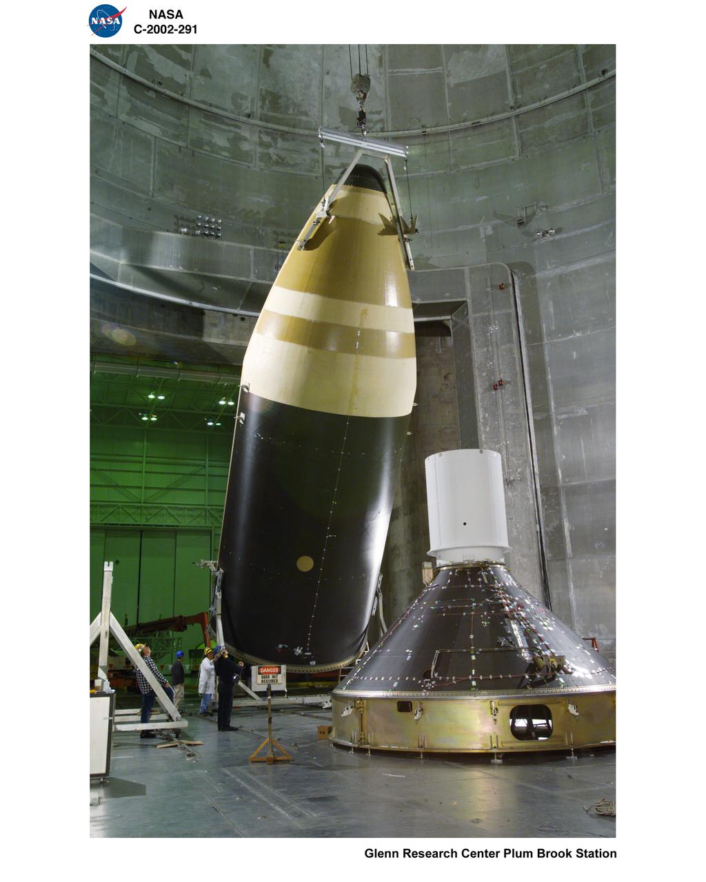
NASA Glenn conducted a test on the Ariane 5 Payload Fairing at Plum Brook’s Space Power Facility (SPF). The test was to qualify a new horizontal pyrotechnic separation system, which blew the two fairing halves apart and away from the payload during flight.
The Abort Test Booster, the rocket which will propel Orion's Launch Abort System and crew module / separation ring during the Ascent Abort -2 (AA-2) flight test, is stacked at the launch pad at Cape Canaveral Air Force Station in Florida on April 12, 2019.
The Abort Test Booster, the rocket which will propel Orion's Launch Abort System and crew module / separation ring during the Ascent Abort -2 (AA-2) flight test, is stacked at the launch pad at Cape Canaveral Air Force Station in Florida on April 12, 2019.
The Abort Test Booster, the rocket which will propel Orion's Launch Abort System and crew module / separation ring during the Ascent Abort -2 (AA-2) flight test, is stacked at the launch pad at Cape Canaveral Air Force Station in Florida on April 12, 2019.
CAPE CANAVERAL, Fla. -- Inside the Launch Equipment Test Facility at NASA’s Kennedy Space in Florida, a second firing of the escape hold down post has occurred during a pyrotechnic bolt test on the Orion ground test vehicle. Lockheed Martin performed tests over a series of days on the explosive bolts that separate Orion from the launch abort system. Data was collected on the effect of shock waves on Orion during the explosive bolt separation. Orion is the exploration spacecraft designed to carry crews to space beyond low Earth orbit. It will provide emergency abort capability, sustain the crew during the space travel and provide safe re-entry from deep space return velocities. The first unpiloted test flight of the Orion is scheduled to launch in 2014 atop a Delta IV rocket and in 2017 on a Space Launch System rocket. For more information, visit http://www.nasa.gov/orion. Photo credit: NASA/Jim Grossmann
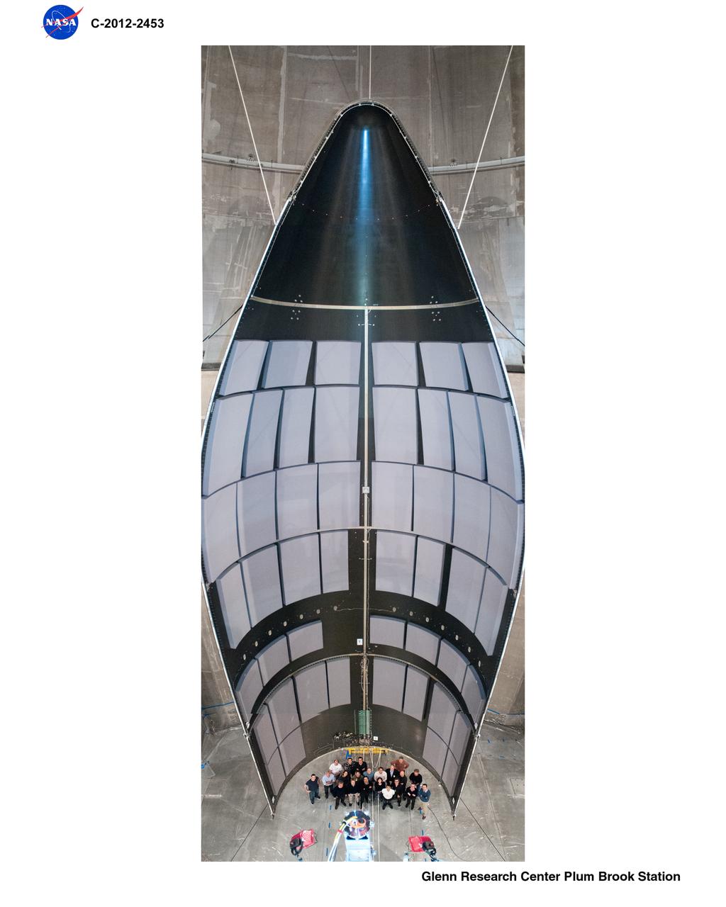
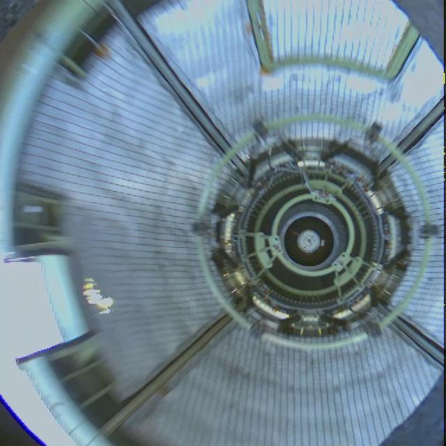
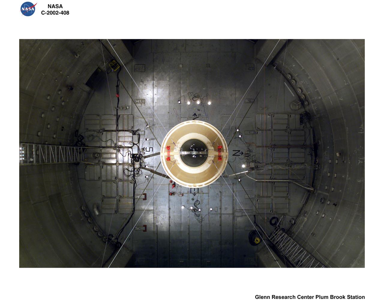
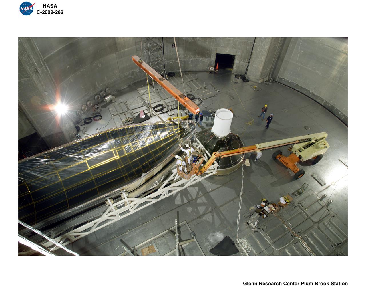
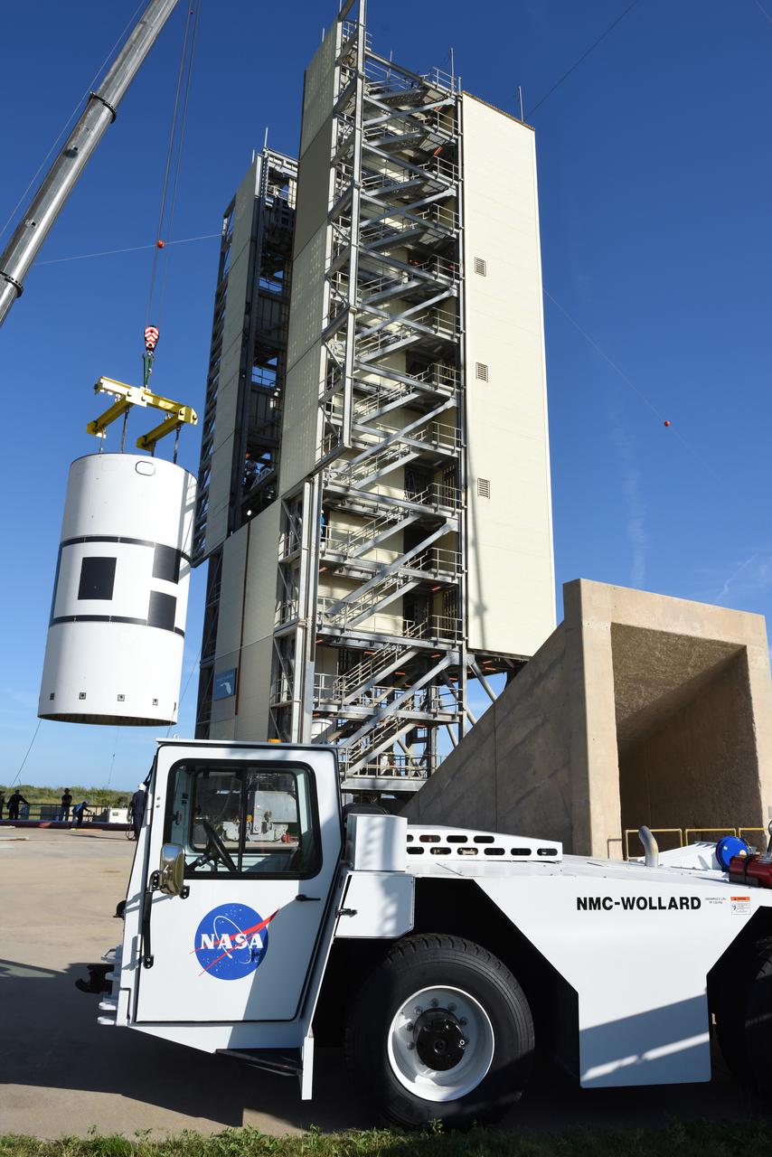
Space Power Facility at Plum Brook Station, RUAG Ariane 5 Shroud Separation Tests. GRC has the world's largest vacuum chamber in the world. This world class facility is host to many space launch vehicle systems tests from customer's in this country and from around the world. Shown here is the post test of a successful rocket shroud separation test. The shroud, or top of a rocket, is jettisoned into two halves with explosive charges to allow the payload to be exposed for deployment. The payload, often time is a satellite, would be sitting atop the center white section shown in the middle of the photo. This photo was taken from on top of the rocket holding the payload and both halves of the rocket shroud looking down at one of the shroud halves and the test crew at the bottom.
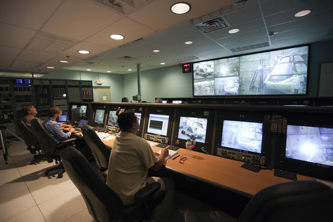
CAPE KENNEDY, Fla. -- Inside the control room at the Launch Equipment Test Facility, or LETF, at NASA’s Kennedy Space Center in Florida, Lockheed Martin engineers monitor the pyrotechnic bolt test on the Orion ground test vehicle at the LETF. Lockheed Martin performed tests over a series of days on the explosive bolts that separate Orion from the launch abort system. Data was collected on the effect of shock waves on Orion during the explosive bolt separation. Orion is the exploration spacecraft designed to carry crews to space beyond low Earth orbit. It will provide emergency abort capability, sustain the crew during the space travel and provide safe re-entry from deep space return velocities. The first unpiloted test flight of the Orion is scheduled to launch in 2014 atop a Delta IV rocket and in 2017 on a Space Launch System rocket. For more information, visit http://www.nasa.gov/orion. Photo credit: NASA/Kim Shiflett
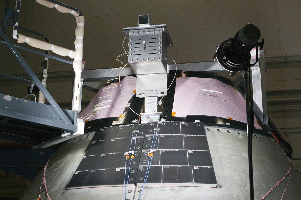
CAPE KENNEDY, Fla. -- Inside the Launch Equipment Test Facility at NASA’s Kennedy Space in Florida, sensors have been placed on the Orion ground test vehicle and cameras placed nearby in order to monitor pyrotechnic bolt tests. Lockheed Martin performed tests over a series of days on the explosive bolts that separate Orion from the launch abort system. Data was collected on the effect of shock waves on Orion during the explosive bolt separation. Orion is the exploration spacecraft designed to carry crews to space beyond low Earth orbit. It will provide emergency abort capability, sustain the crew during the space travel and provide safe re-entry from deep space return velocities. The first unpiloted test flight of the Orion is scheduled to launch in 2014 atop a Delta IV rocket and in 2017 on a Space Launch System rocket. For more information, visit http://www.nasa.gov/orion. Photo credit: NASA/Kim Shiflett
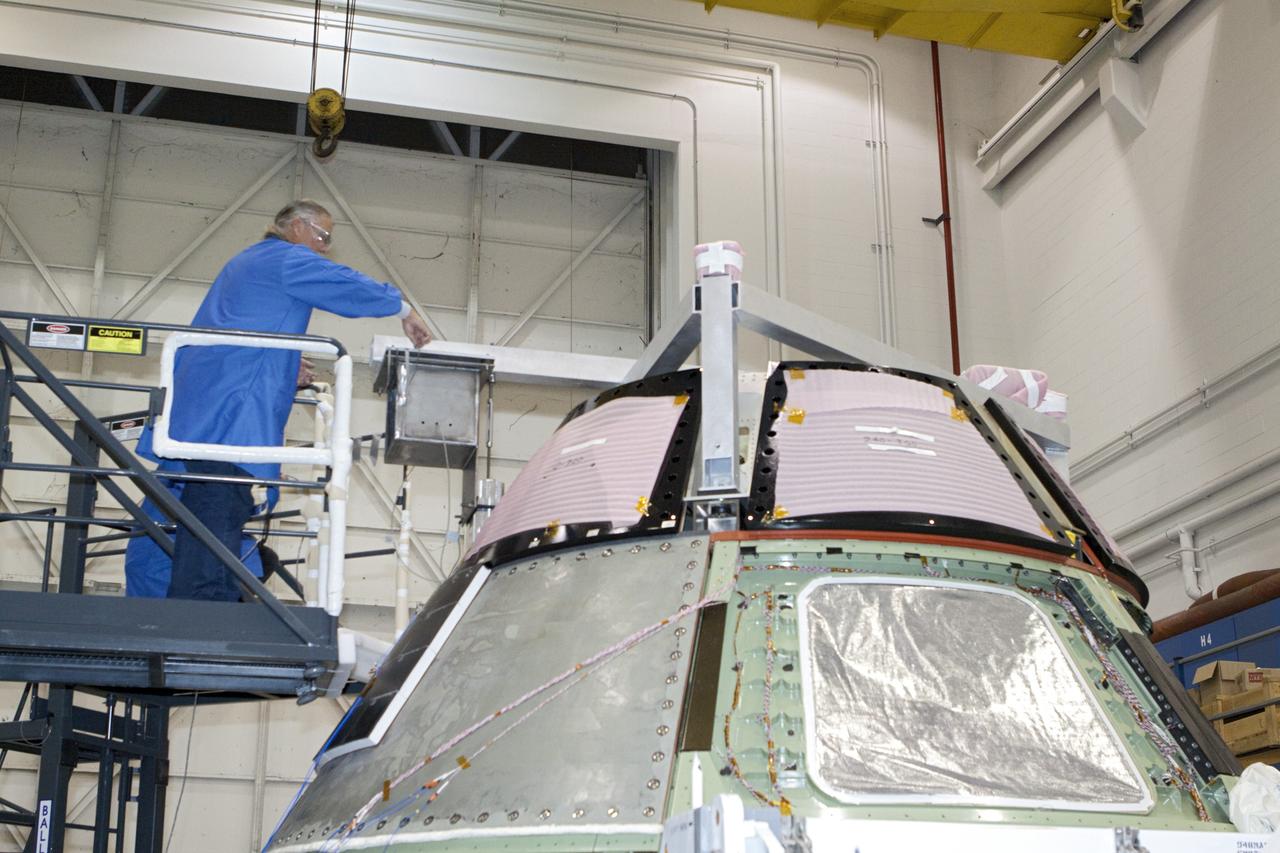
CAPE KENNEDY, Fla. -- Inside the Launch Equipment Test Facility at NASA’s Kennedy Space in Florida, a Lockheed Martin technician prepares the Orion ground test vehicle for a pyrotechnic bolt test. Lockheed Martin performed tests over a series of days on the explosive bolts that separate Orion from the launch abort system. Data was collected on the effect of shock waves on Orion during the explosive bolt separation. Orion is the exploration spacecraft designed to carry crews to space beyond low Earth orbit. It will provide emergency abort capability, sustain the crew during the space travel and provide safe re-entry from deep space return velocities. The first unpiloted test flight of the Orion is scheduled to launch in 2014 atop a Delta IV rocket and in 2017 on a Space Launch System rocket. For more information, visit http://www.nasa.gov/orion. Photo credit: NASA/Kim Shiflett
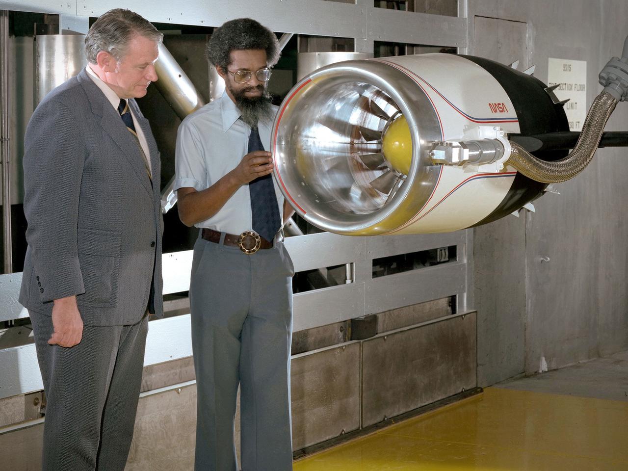
Center Director John McCarthy, left, and researcher Al Johns pose with a one-third scale model of a Grumman Aerospace tilt engine nacelle for Vertical and Short Takeoff and Landing (V/STOL) in the 9- by 15-Foot Low Speed Wind Tunnel at the National Aeronautics and Space Administration (NASA) Lewis Research Center. Lewis researchers had been studying tilt nacelle and inlet issues for several years. One area of concern was the inlet flow separation during the transition from horizontal to vertical flight. The separation of air flow from the inlet’s internal components could significantly stress the fan blades or cause a loss of thrust. In 1978 NASA researchers Robert Williams and Al Johns teamed with Grumman’s H.C. Potonides to develop a series of tests in the Lewis 9- by 15-foot tunnel to study a device designed to delay the flow separation by blowing additional air into the inlet. A jet of air, supplied through the hose on the right, was blown over the inlet surfaces. The researchers verified that the air jet slowed the flow separation. They found that the blowing on boundary layer control resulted in a doubling of the angle-of-attack and decreases in compressor blade stresses and fan distortion. The tests were the first time the concept of blowing air for boundary layer control was demonstrated. Boundary layer control devices like this could result in smaller and lighter V/STOL inlets.
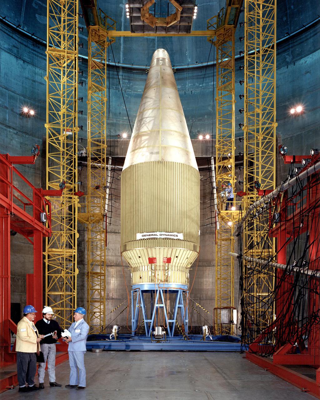
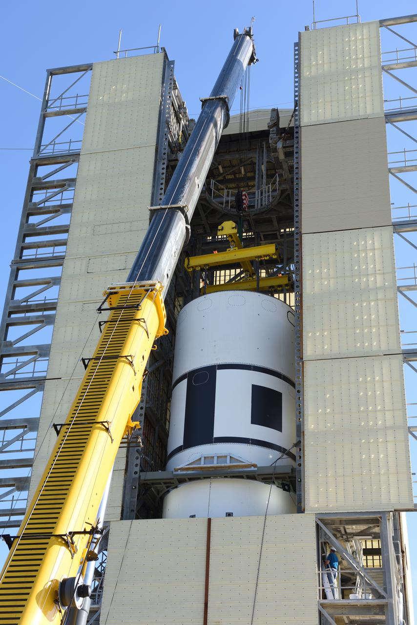
Employees at the Space Power Facility (SPF) at Plum Brook Station tested a new generation of Atlas/Centaur launch vehicles. General Dynamics conducted the tests December 22 and January 3, 1990 to determine the flight readiness of a new 14-foot diameter payload fairing. The fairing will accommodate new weather satellites, the U.S. Air Force Combined Release and Radiation Effects (CRRES) satellite, and other future payloads. At a simulated altitude of 85,000 feet, the cone-shaped fairing separated in half from a hinge at the bottom. Half of the fairing was then released from the test stack and recovered in a catch-net. The payload fairing separations were the first tests of major space hardware to be conducted in the SPF in more than 15 years.
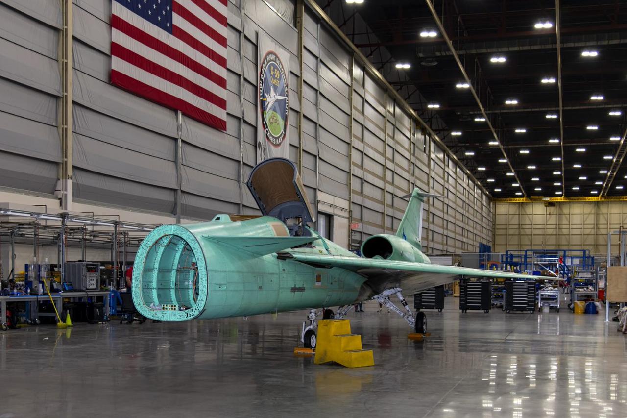
The X-59 arrives home in Palmdale, California after completing important structural and fuel tests at the Lockheed Martin facility in Ft. Worth, Texas. The nose, which is not installed in this image, was removed prior to the transport home and arrived separately to the facility. This is part of NASA’s Quesst mission which plans to help enable supersonic air travel over land.
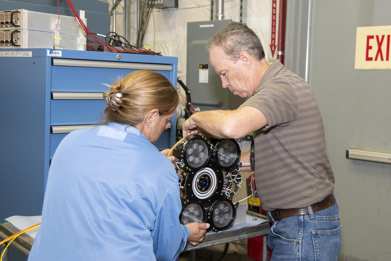
Dan Nolan, who with engineer Lucas Moxey developed the camera system shown in the photo, is seen working with April Torres to prepare it for vibration testing at NASA’s Armstrong Flight Research Center. The camera system is designed to operate as part of the Orion AA-2 test article’s abort test booster/separation ring developmental flight instrumentation subsystem. The testing proved the camera system could function and endure the predicted flight environment.
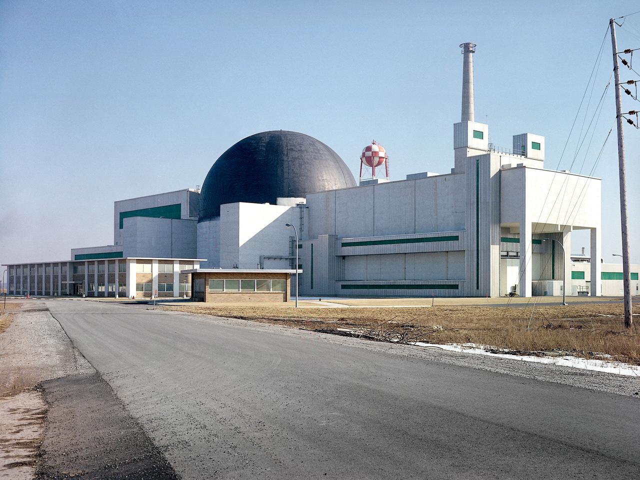
Exterior view of the Space Power Facility at the National Aeronautics and Space Administration’s (NASA) Plum Brook Station in Sandusky, Ohio. The $28.4-million facility, which began operations in 1969, is the largest high vacuum chamber ever built. The chamber is 100 feet in diameter and 120 feet high. It produces a vacuum deep enough to simulate the conditions at 300 miles altitude. The facility can sustain a high vacuum; simulate solar radiation via a 4-megawatt quartz heat lamp array, solar spectrum by a 400-kilowatt arc lamp, and cold environments. The Space Power Facility was originally designed to test nuclear power sources for spacecraft during long durations in a space atmosphere, but it was never used for that purpose. The facility’s first test in 1970 involved a 15 to 20-kilowatt Brayton Cycle Power System for space applications. Three different methods of simulating solar heat were employed during the Brayton tests. The facility was also used for jettison tests of the Centaur Standard Shroud. The shroud was designed for the new Titan-Centaur rocket that was scheduled to launch the Viking spacecraft to Mars. The new shroud was tested under conditions that simulated the time from launch to the separation of the stages. Test programs at the facility include high-energy experiments, shroud separation tests, Mars Lander system tests, deployable Solar Sail tests and International Space Station hardware tests.
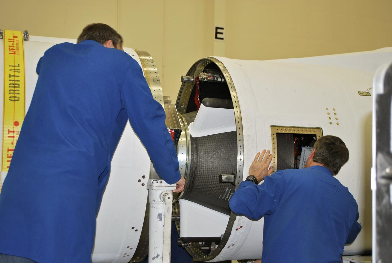
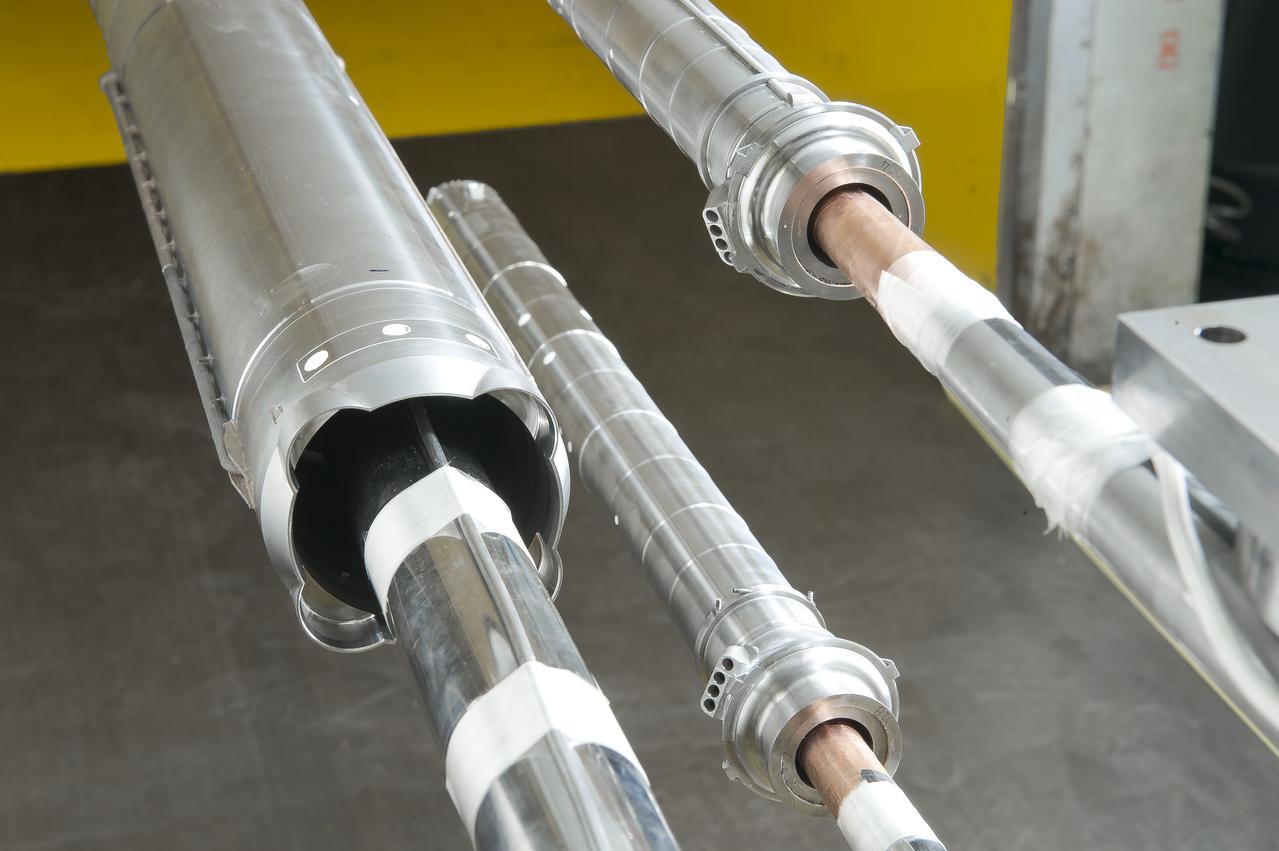
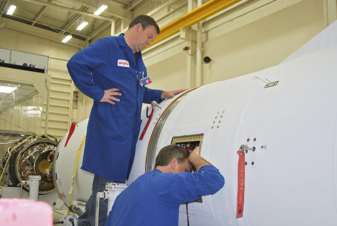
VANDENBERG AFB, Calif. – Technicians monitor the movement of the second stage of an Orbital Sciences Pegasus rocket into the first stage before a separation test is conducted. The Pegasus is being processed to launch NASA's Interface Region Imaging Spectrograph mission, known as IRIS. Photo credit: Randy Beaudoin, VAFB
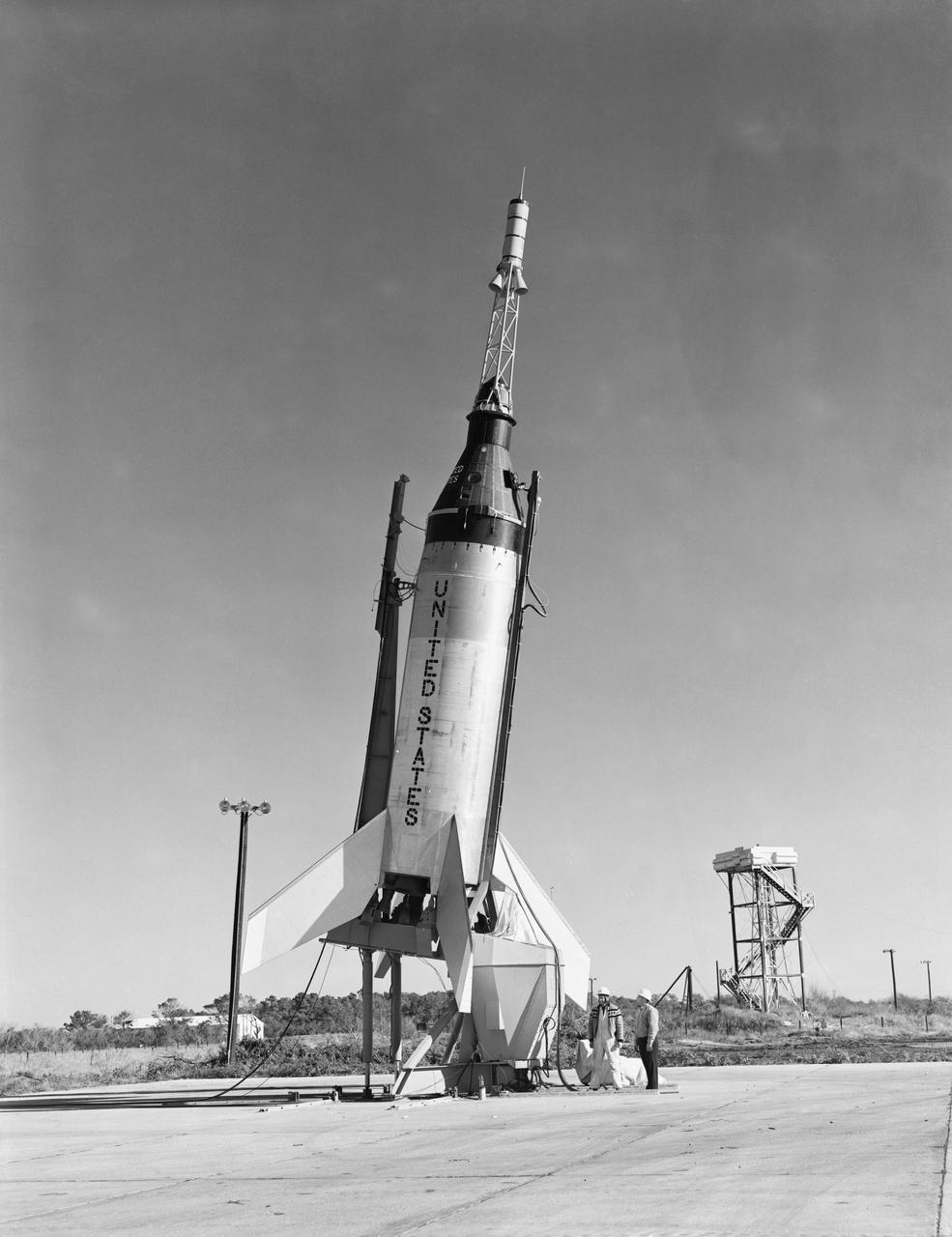
G60-02552 (8 Nov. 1960) --- Little Joe-5 prelaunch fittings shot before flight from Wallops Island. The suborbital test flight was to qualify the capsule system. The capsule did not separate from the booster. Photo credit: NASA
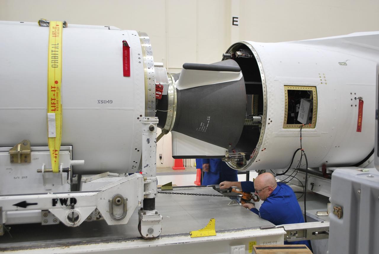
VANDENBERG AFB, Calif. – A technician moves the second stage of an Orbital Sciences Pegasus rocket into the first stage before a separation test is conducted. The Pegasus is being processed to launch NASA's Interface Region Imaging Spectrograph mission, known as IRIS. Photo credit: Randy Beaudoin, VAFB
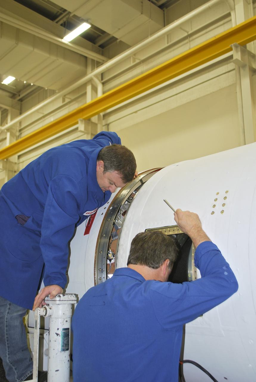
VANDENBERG AFB, Calif. – Technicians monitor the movement of the second stage of an Orbital Sciences Pegasus rocket into the first stage before a separation test is conducted. The Pegasus is being processed to launch NASA's Interface Region Imaging Spectrograph mission, known as IRIS. Photo credit: Randy Beaudoin, VAFB
VANDENBERG AFB, Calif. – Technicians monitor the movement of the second stage of an Orbital Sciences Pegasus rocket into the first stage before a separation test is conducted. The Pegasus is being processed to launch NASA's Interface Region Imaging Spectrograph mission, known as IRIS. Photo credit: Randy Beaudoin, VAFB
VANDENBERG AFB, Calif. – A technician monitors the movement of the second stage of an Orbital Sciences Pegasus rocket into the first stage before a separation test is conducted. The Pegasus is being processed to launch NASA's Interface Region Imaging Spectrograph mission, known as IRIS. Photo credit: Randy Beaudoin, VAFB
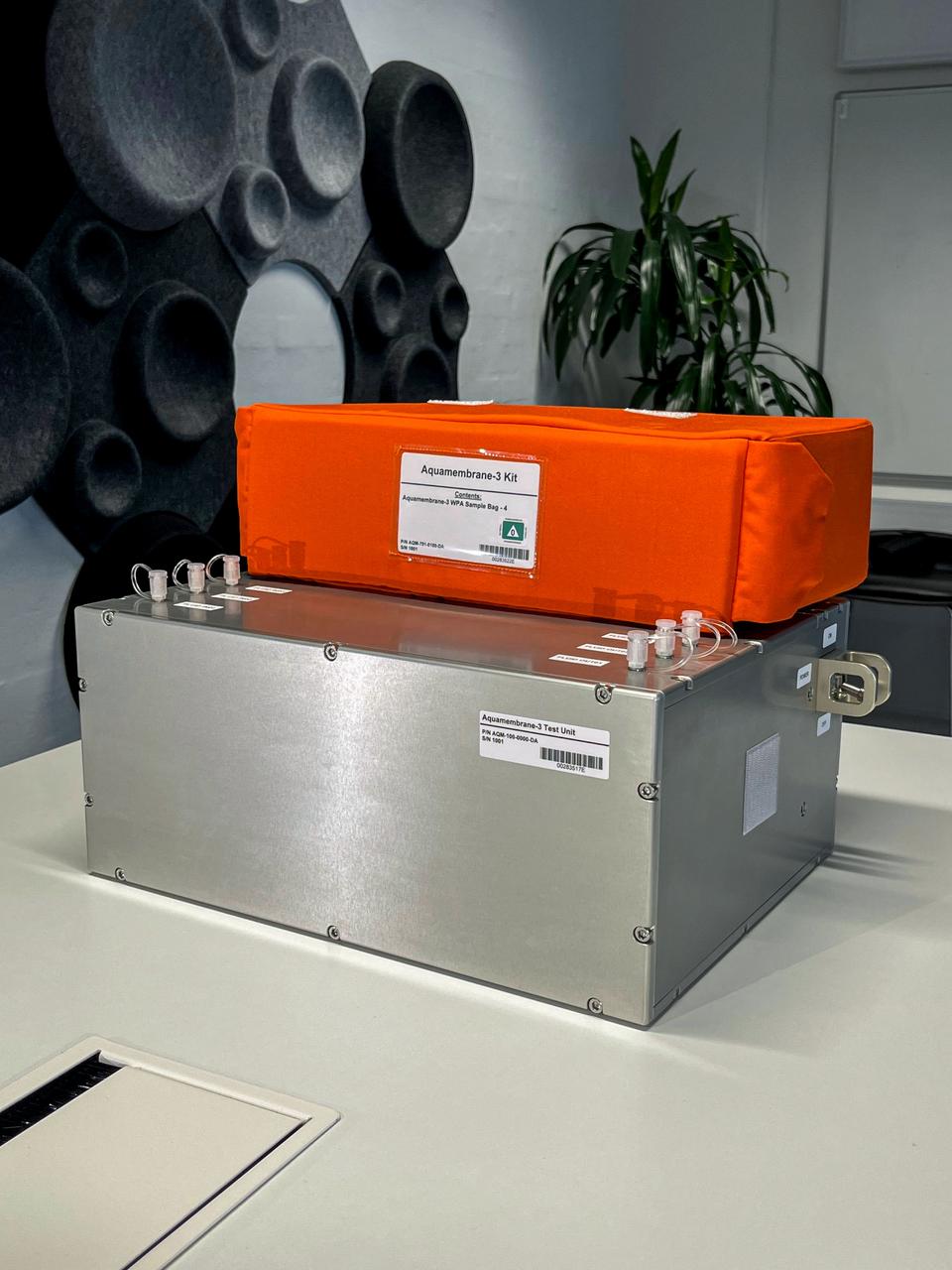
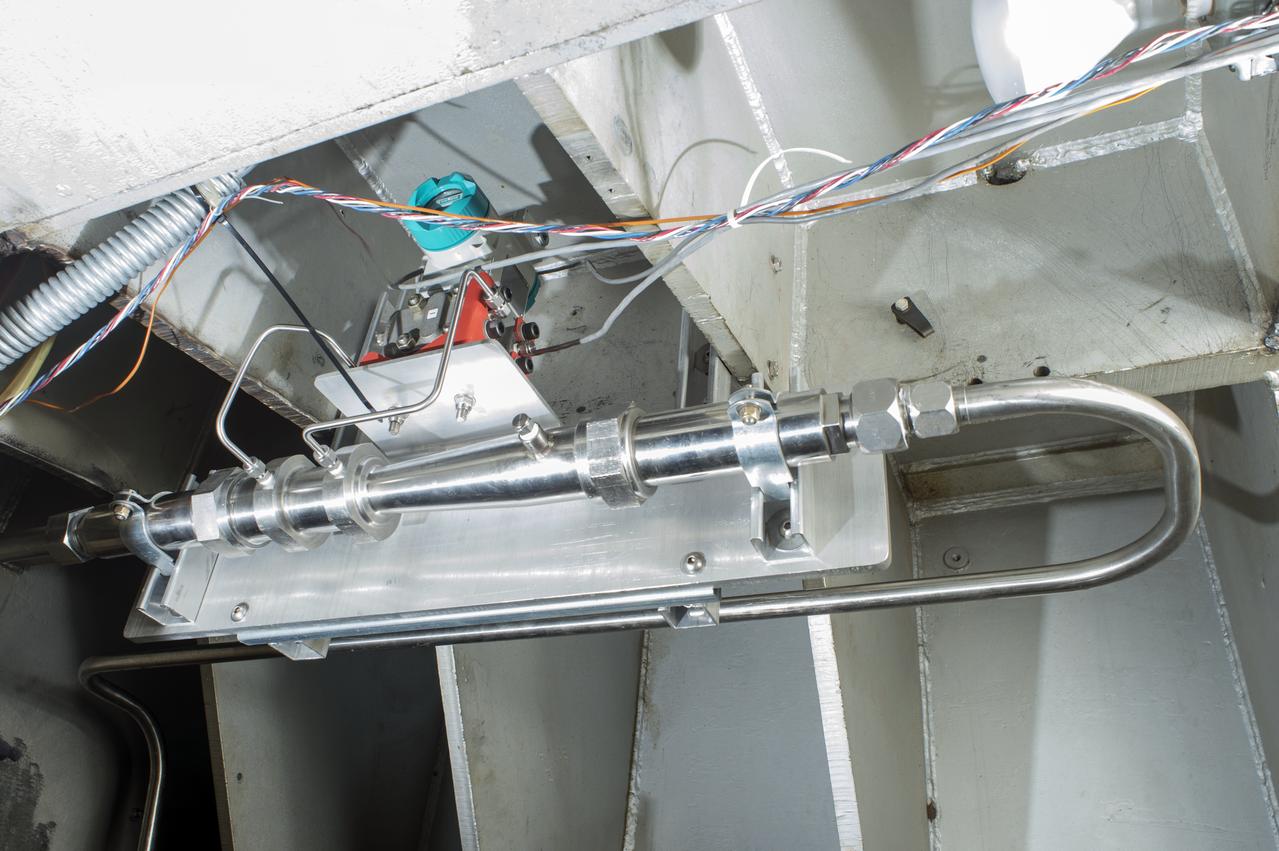
jsc2023e055872 (10/5/2023) --- The Testing Contaminant Rejection of Aquaporin Inside® HFFO Module (Aquamembrane-3) hardware consists of three separate and parallel systems to quantify the membrane's water flux and contamination rejection in microgravity, which are key parameters for a full water recovery system. This image shows the complete experiment hardware.
VANDENBERG AFB, Calif. – Technicians monitor the movement of the second stage of an Orbital Sciences Pegasus rocket into the first stage before a separation test is conducted. The Pegasus is being processed to launch NASA's Interface Region Imaging Spectrograph mission, known as IRIS. Photo credit: Randy Beaudoin, VAFB

Test of Unmanned Aircraft Systems Traffic Management (UTM) technical capability Level 2 (TCL2) at Reno-Stead Airport, Nevada. During the test, five drones simultaneously crossed paths, separated by altitude. Two drones flew beyond visual line-of-sight and three flew within line-of-sight of their operators. Precision Hawk pilot readies Lancaster Mark 3 UAS for test flight.
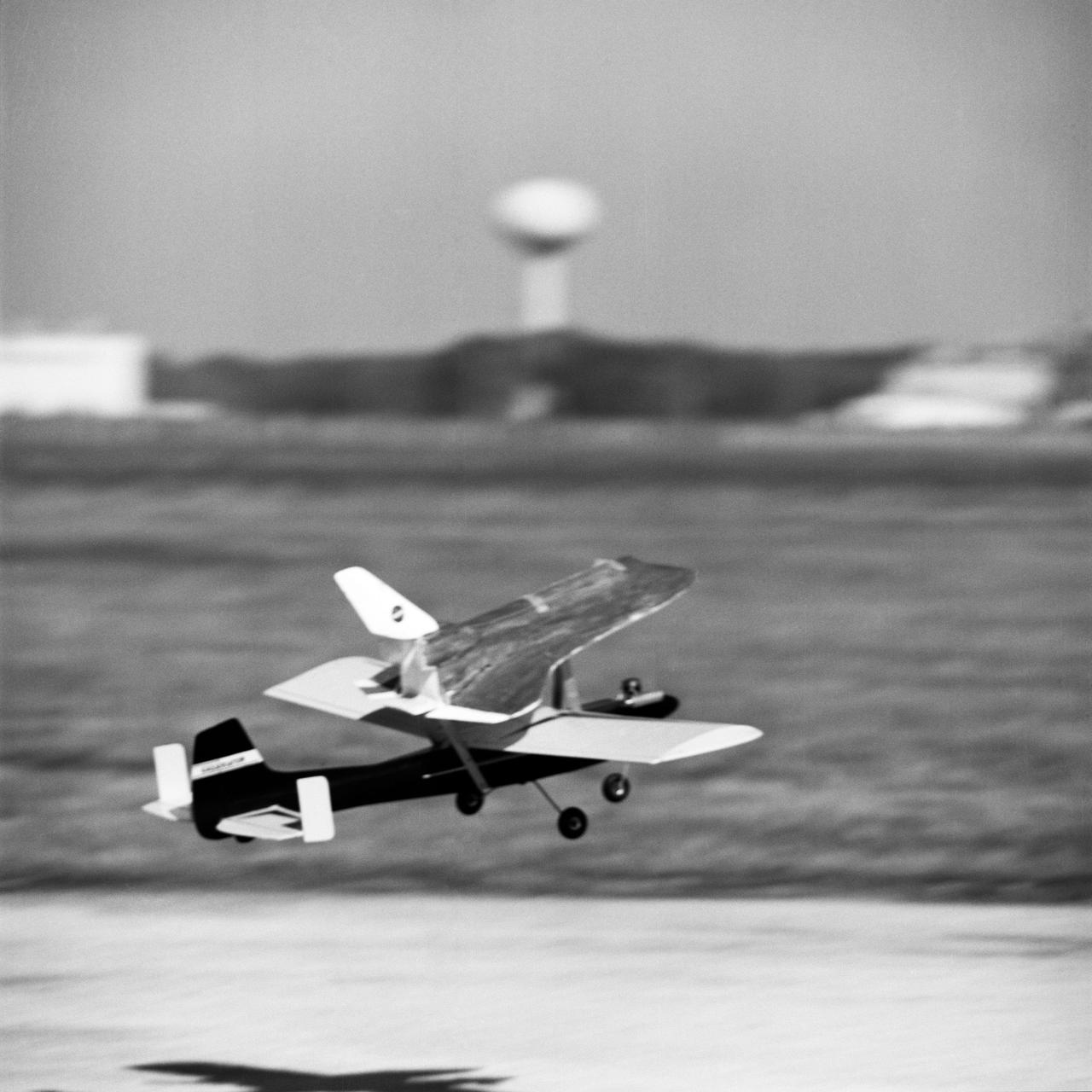
Owen Morris and John Kiker are seen in this series of photographs documenting a mini-Approach and Landing Test conducted on the Bldg. 14 Antenna Test Range, using a 1/40th-scale model Orbiter and a model airplane. The test was flown to study Orbiter control characteristics and separation dynamics. Simulated Orbiter being dropped from 747. JSC, HOUSTON, TX. S75-33949 thru S75-33957

Test of Unmanned Aircraft Systems Traffic Management (UTM) technical capability Level 2 (TCL2) at Reno-Stead Airport, Nevada. During the test, five drones simultaneously crossed paths, separated by altitude. Two drones flew beyond visual line-of-sight and three flew within line-of-sight of their operators. Precision Hawk pilot launches UAS Lancaster Mark 3, one of 11 vehicles in the UTM TCL2 demonstration that will fly beyond line of sight of the pilot in command in Nevada test.

This photograph shows an early moment of the first test flight of the Saturn V vehicle for the Apollo 4 mission, photographed by a ground tracking camera, on the morning of November 9, 1967. This mission was the first launch of the Saturn V launch vehicle. Objectives of the unmarned Apollo 4 test flight were to obtain flight information on launch vehicle and spacecraft structural integrity and compatibility, flight loads, stage separation, and subsystems operation including testing of restart of the S-IVB stage, and to evaluate the Apollo command module heat shield.