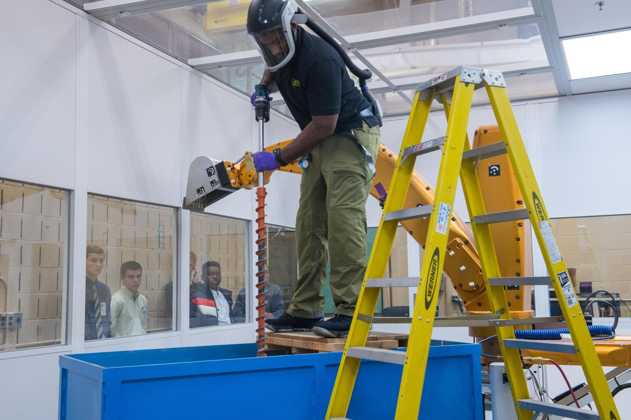
High School Student Shadowing Program

Girders overhead cast shadows on the walls and floor of a support building under construction, part of the new $8 million Reusable Launch Vehicle (RLV) Support Complex at Kennedy Space Center. The building is to be used for related ground support equipment and administrative/technical support. The RLV complex also includes a multi-purpose hangar. The complex will be available to accommodate the Space Shuttle; the X-34 RLV technology demonstrator; the L-1011 carrier aircraft for Pegasus and X-34; and other RLV and X-vehicle programs. The facility, jointly funded by the Spaceport Florida Authority, NASA's Space Shuttle Program and KSC, will be operational in early 2000
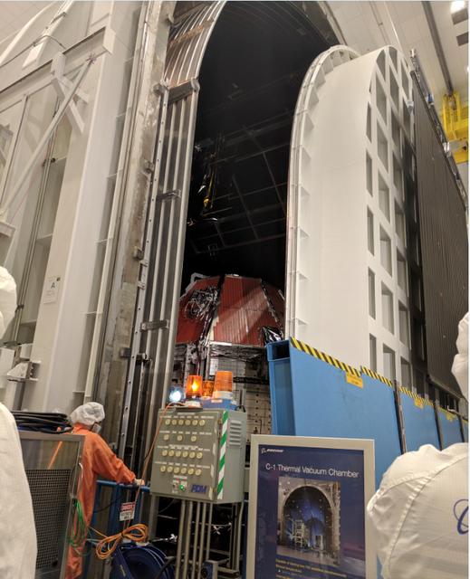
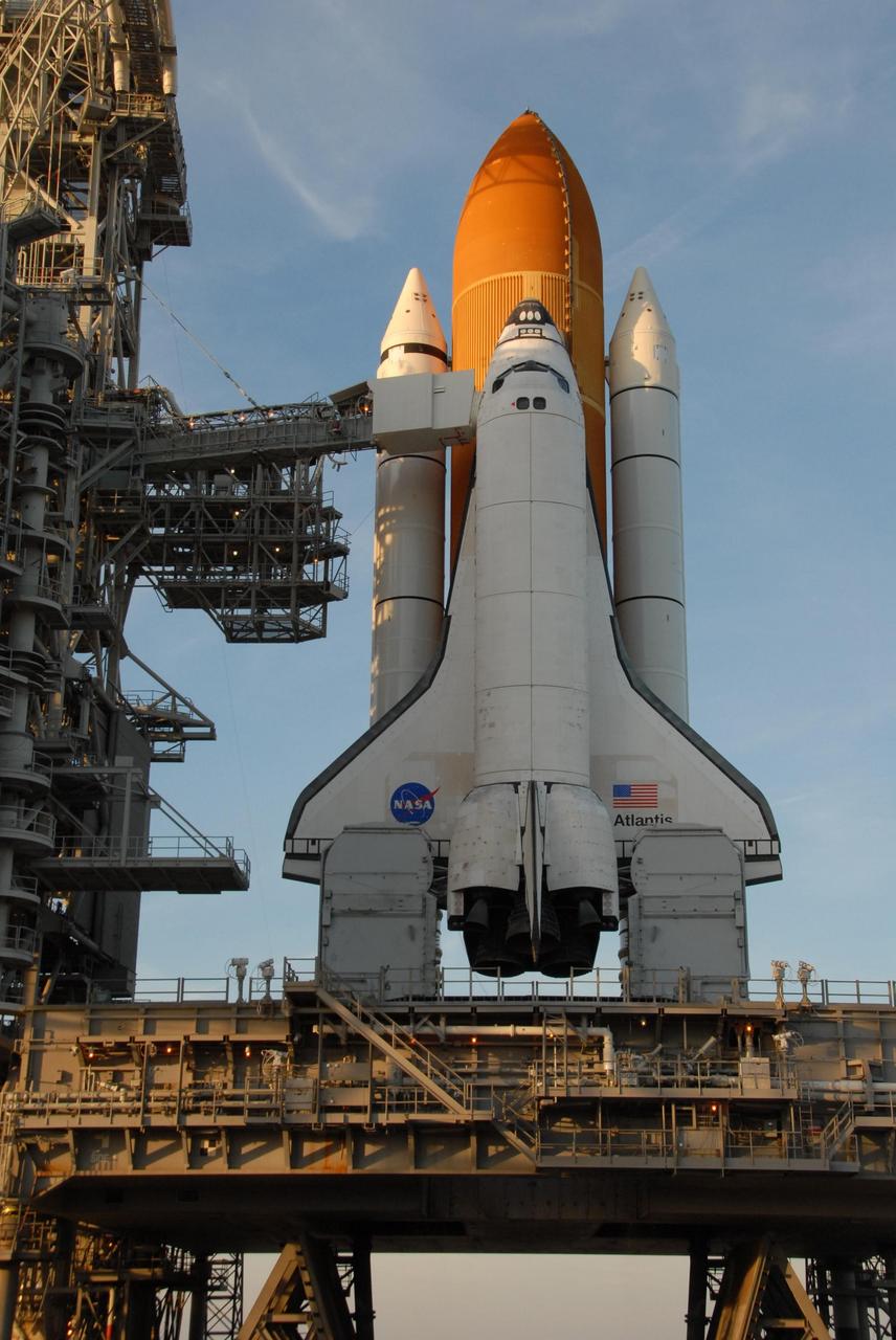
Boeing’s Crew Flight Test Starliner prepares for thermal vacuum testing at Boeing’s Space Environment Test Facility in El Segundo, Calif. During this test series, test teams outfitted Starliner with hot plates and radiators and placed in a vacuum chamber that could also be filled with a cryogenic nitrogen shroud. This allowed Boeing teams to simulate the vacuum environment in space as well as the drastic temperature swings Starliner will see as it moves to and from direct sunlight and the Earth’s shadow. This is the Starliner that will be used for Boeing’s Crew Flight Test as part of NASA’s Commercial Crew Program, which is working with Boeing to return human spaceflight launches to the space station from U.S. soil.
Boeing’s Crew Flight Test Starliner prepares for thermal vacuum testing at Boeing’s Space Environment Test Facility in El Segundo, Calif. During this test series, test teams outfitted Starliner with hot plates and radiators and placed in a vacuum chamber that could also be filled with a cryogenic nitrogen shroud. This allowed Boeing teams to simulate the vacuum environment in space as well as the drastic temperature swings Starliner will see as it moves to and from direct sunlight and the Earth’s shadow. This is the Starliner that will be used for Boeing’s Crew Flight Test as part of NASA’s Commercial Crew Program, which is working with Boeing to return human spaceflight launches to the space station from U.S. soil.
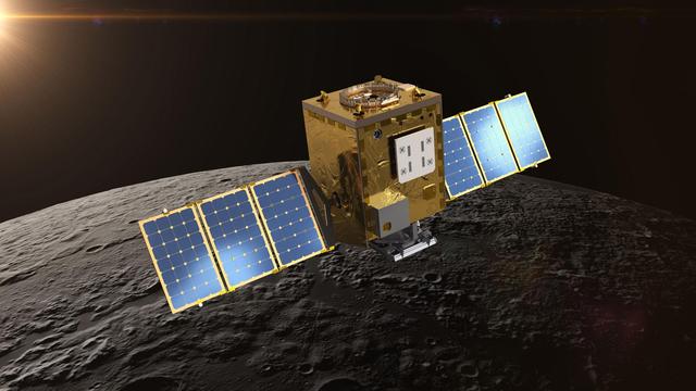
Peering into the Moon's permanently shadowed regions, Lunar Trailblazer will detect signatures of water ice in reflected light, and it will pinpoint the locations of micro-cold traps less than a football field in size. The small satellite will collect measurements at multiple times of day over sunlit regions, helping scientists understand if the water signature on the illuminated surface changes as the lunar surface temperature changes by hundreds of degrees over the course of a lunar day. The goal is to produce high-resolution maps to locate water ice in support of NASA's Artemis Program, which aims to establish a sustainable human presence on the Moon and prepare for future missions to Mars. https://photojournal.jpl.nasa.gov/catalog/PIA24161
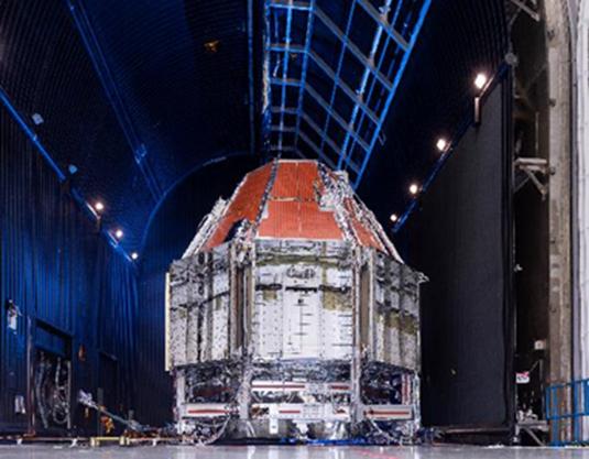
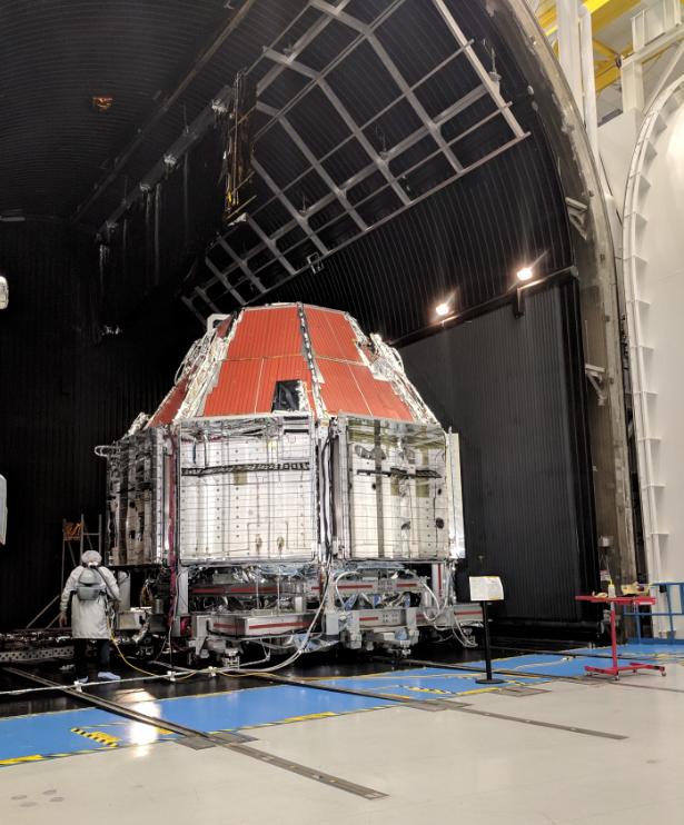
Boeing’s Crew Flight Test CST-100 Starliner prepares for thermal vacuum testing at Boeing’s Space Environment Test Facility in El Segundo, Calif. During this test series, test teams outfitted Starliner with hot plates and radiators and placed in a vacuum chamber that could also be filled with a cryogenic nitrogen shroud. This allowed Boeing teams to simulate the vacuum environment in space as well as the drastic temperature swings Starliner will see as it moves to and from direct sunlight and the Earth’s shadow. This is the Starliner that will be used for Boeing’s Crew Flight Test as part of NASA’s Commercial Crew Program, which is working with Boeing to return human spaceflight launches to the space station from U.S. soil.

NASA astronaut Megan McArthur points to the shadow of the Gateway Arch on the Mississippi River in St. Louis while showing images of National Parks taken from the International Space Station during Expeditions 65 and 66 during a presentation to leadership and rangers who participate in the National Park Service’s astronomy and dark sky programs, Thursday, June 9, 2022 at the U.S. Department of the Interior in Washington, DC. McArthur, NASA astronaut Shane Kimbrough, Japan Aerospace Exploration Agency (JAXA) astronaut Akihiko Hoshide, and ESA (European Space Agency) astronaut Thomas Pesquet, flew on NASA’s SpaceX Crew-2 mission, the second crew rotation mission to the International Space Station as part of the agency’s Commercial Crew Program, and spent 198 days aboard the orbiting laboratory as part of Expeditions 65 and 66. Photo Credit: (NASA/Joel Kowsky)
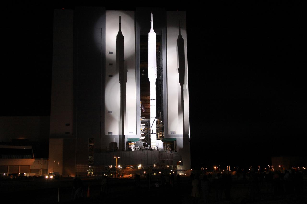
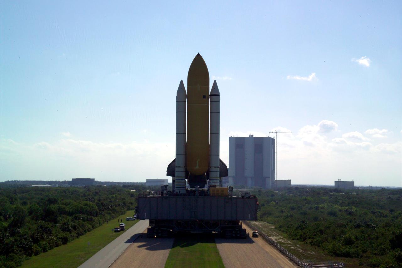
CAPE CANAVERAL, Fla. – The 327-foot-tall Ares I-X rocket casts shadows on the massive Vehicle Assembly Building at NASA's Kennedy Space Center in Florida as it heads to Launch Pad 39B aboard a crawler-transporter. The move to the launch pad, known as "rollout," began at 1:39 a.m. EDT. The transfer of the pad from the Space Shuttle Program to the Constellation Program took place May 31. Modifications made to the pad include the removal of shuttle unique subsystems, such as the orbiter access arm and a section of the gaseous oxygen vent arm, along with the installation of three 600-foot lightning towers, access platforms, environmental control systems and a vehicle stabilization system. Part of the Constellation Program, the Ares I-X is the test vehicle for the Ares I. The Ares I-X flight test is targeted for Oct. 27. For information on the Ares I-X vehicle and flight test, visit http://www.nasa.gov/aresIX. Photo credit: NASA/Jack Pfaller
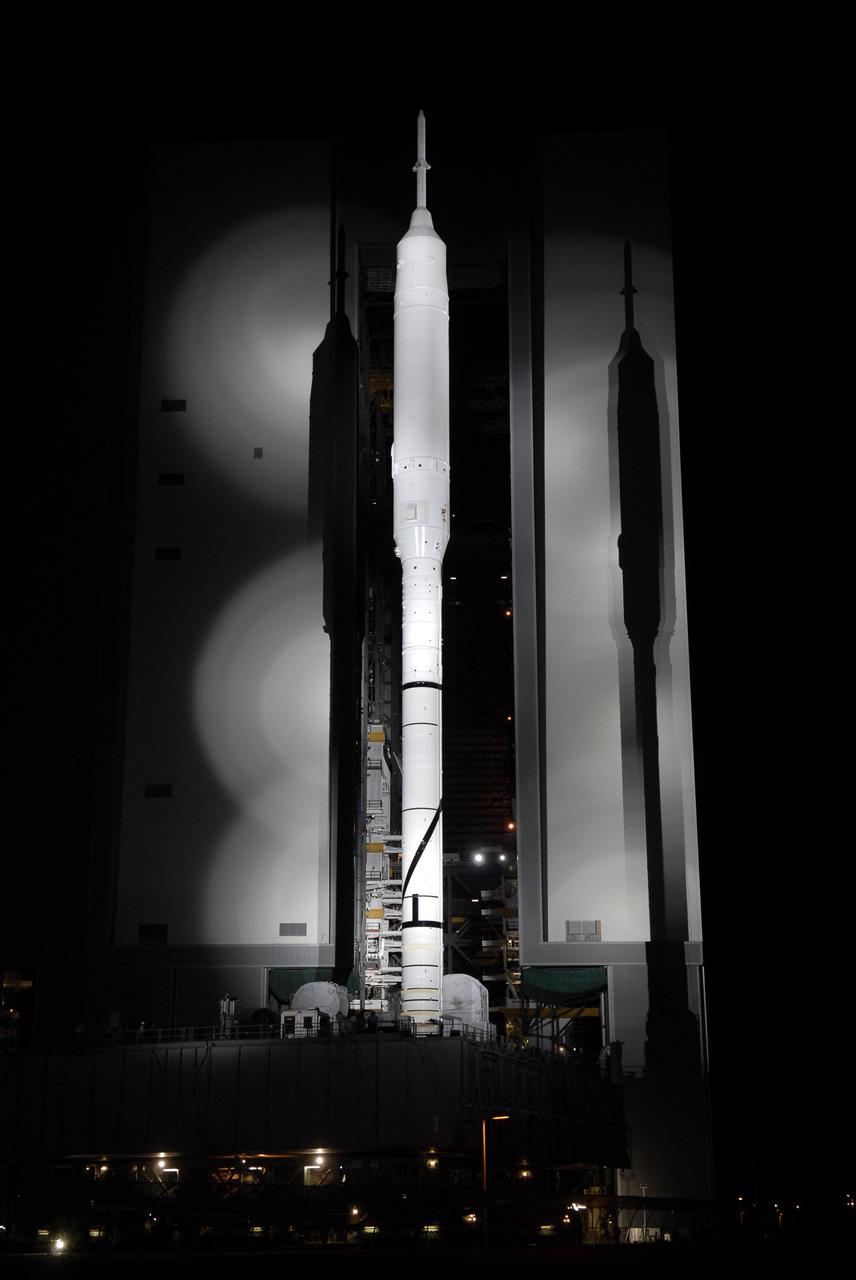
CAPE CANAVERAL, Fla. - Bathed in light, the 327-foot-tall Ares I-X rocket casts shadows on the massive Vehicle Assembly Building at NASA's Kennedy Space Center in Florida as it heads to Launch Pad 39B aboard a crawler-transporter. The move to the launch pad, known as "rollout," began at 1:39 a.m. EDT. The transfer of the pad from the Space Shuttle Program to the Constellation Program took place May 31. Modifications made to the pad include the removal of shuttle unique subsystems, such as the orbiter access arm and a section of the gaseous oxygen vent arm, along with the installation of three 600-foot lightning towers, access platforms, environmental control systems and a vehicle stabilization system. Part of the Constellation Program, the Ares I-X is the test vehicle for the Ares I. The Ares I-X flight test is targeted for Oct. 27. For information on the Ares I-X vehicle and flight test, visit http://www.nasa.gov/aresIX. Photo credit: NASA/Kim Shiflett
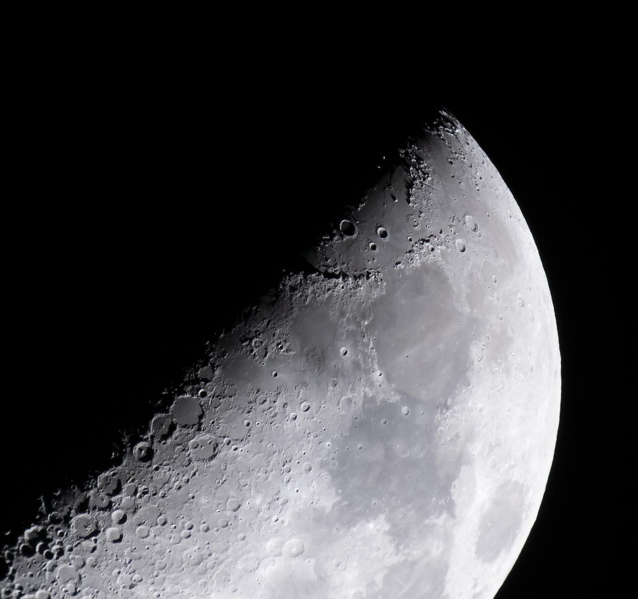
NASA’s Exploration Ground Systems’ Program Manager Shawn Quinn captured this image of the Hadley–Apennine region of the moon including the Apollo 15 landing site (very near the edge of the shadow of one of the lunar mountains in the area). Image is a crop of a full frame image. Apollo 11, 16 and 17 landing sites are also visible in this image. Hadley–Apennine is a region on the near side of Earth's Moon that served as the landing site for the American Apollo 15 mission, the fourth crewed landing on the Moon and the first of the "J-missions", in July 1971. The site is located on the eastern edge of Mare Imbrium on a lava plain known as Palus Putredinis. Hadley–Apennine is bordered by the Montes Apenninus (often referred to as "Apennine Front"), a mountain range, and Hadley Rille, a meandering channel, on the east and west, respectively.
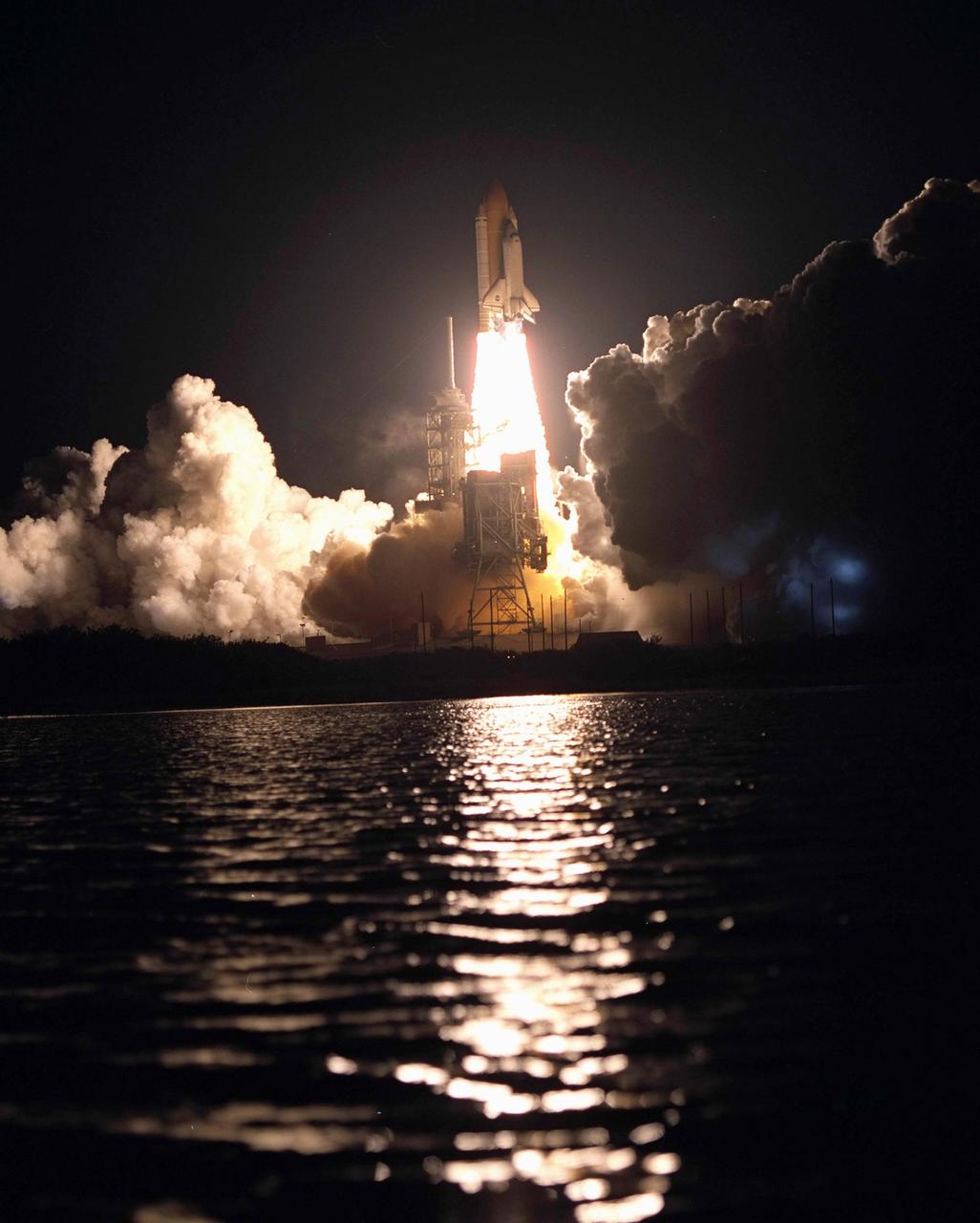
KENNEDY SPACE CENTER, Fla. - With its fiery exhaust casting a beam across the water and billows of smoke casting shadows, Space Shuttle Columbia roars into the pre-dawn sky on mission STS-109. Liftoff occurred at 6:22:02:08 a.m. EST (11:22:02:08 GMT). This was the 27th flight of the vehicle and 108th in the history of the Shuttle program. The goal of mission STS-109 is the maintenance and upgrade of the Hubble Space Telescope, to be carried out in five spacewalks. The crew comprises Commander Scott D. Altman, Pilot Duane G. Carey, Payload Commander John M. Grunsfeld, and Mission Specialists Nancy Jane Currie, Richard M. Linnehan, James H. Newman and Michael J. Massimino. After the 11-day mission, Columbia is expected to return to KSC March 12 about 4:35 a.m. EST (09:35 GMT).
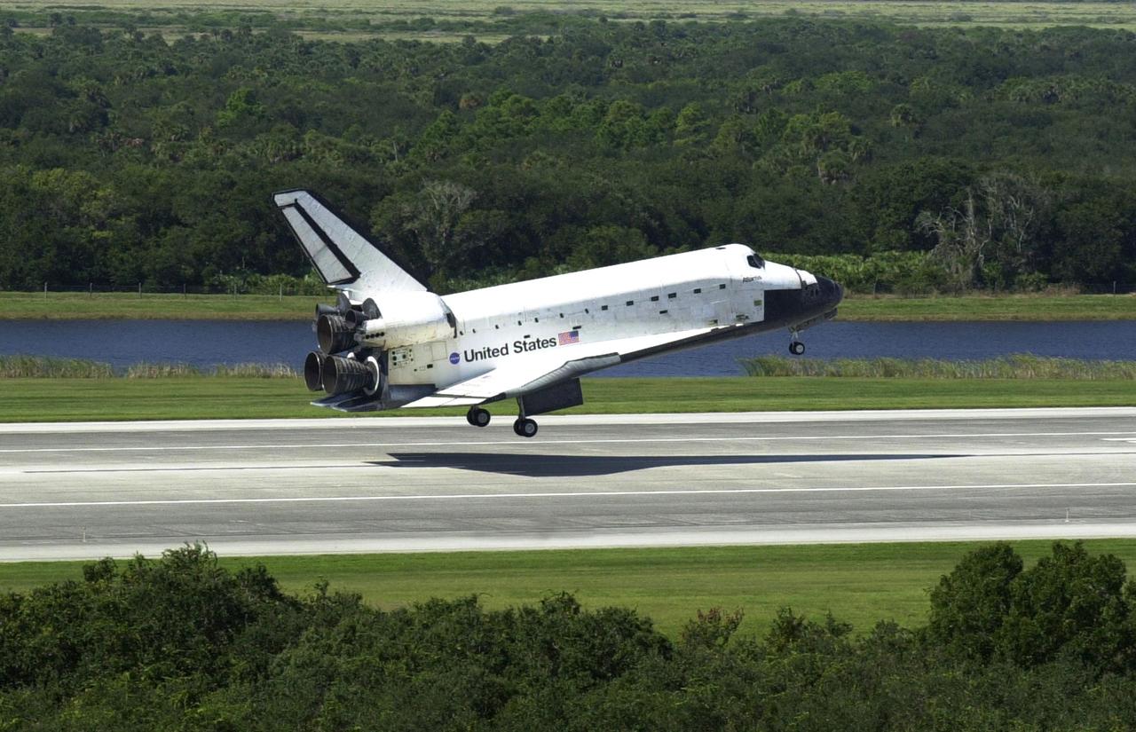
KENNEDY SPACE CENTER, FLA. - Its shadow precedes it as Space Shuttle Atlantis drops to the runway at the Shuttle Landing Facility, completing the 4.5-million-mile journey to the International Space Station. Main gear touchdown occurred at 11:43:40 a.m. EDT; nose gear touchdown at 11:43:48 a.m.; and wheel stop at 11:44:35 a.m. Mission elapsed time was 10:19:58:44. Mission STS-112 expanded the size of the Station with the addition of the S1 truss segment. The returning crew of Atlantis are Commander Jeffrey Ashby, Pilot Pamela Melroy, and Mission Specialists David Wolf, Piers Sellers, Sandra Magnus and Fyodor Yurchikhin. This landing is the 60th at KSC in the history of the Shuttle program. .
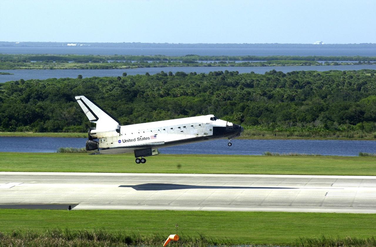
KENNEDY SPACE CENTER, FLA. -- Space Shuttle Atlantis casts a needle-shaped shadow as it drops to the runway at the Shuttle Landing Facility, completing the 4.5-million-mile journey to the International Space Station. Main gear touchdown occurred at 11:43:40 a.m. EDT; nose gear touchdown at 11:43:48 a.m.; and wheel stop at 11:44:35 a.m. Mission elapsed time was 10:19:58:44. Mission STS-112 expanded the size of the Station with the addition of the S1 truss segment. The returning crew of Atlantis are Commander Jeffrey Ashby, Pilot Pamela Melroy, and Mission Specialists David Wolf, Piers Sellers, Sandra Magnus and Fyodor Yurchikhin. This landing is the 60th at KSC in the history of the Shuttle program.

Daniel Bernatowicz, Chief of the Advanced Power Systems Branch at the National Aeronautics and Space Administration (NASA) Lewis Research Center, examines a 20-foot section of a solar mirror being fabricated in the Jig Bore Room of the Technical Services Building. NASA Lewis was conducting a wide-ranging effort to explore methods of generating electrical power for spacecraft. One method employed a large parabolic mirror to concentrate the sun’s energy. The mirror had to remain rigid and withstand micrometeoroids, but remain light and compact enough to be easily launched. In 1963 Bernatowicz and his researchers undertook a program to design a solar mirror to work with the Brayton cycle system on a space station. The mirror in this photograph was prepared for a conference on Advanced Technology in Space Power Systems held at Lewis in late August 1966. Lewis experts discussed advances with batteries, fuel cells, isotope and thermoelectric generators, and the SNAP-8 space power system. Lewis was developing several types of solar mirrors to work with a Brayton cycle electric generating system. The mirror’s 12 sections were shaped using a unique forming process developed at Lewis, coated with an epoxy, and plated with aluminum. The mirror concentrated the Sun's rays on a heat storage receiver containing lithium fluoride. This material was heated to produce power in a turbogenerator system, while additional heat was stored for use when the unit was in the Earth's shadow.
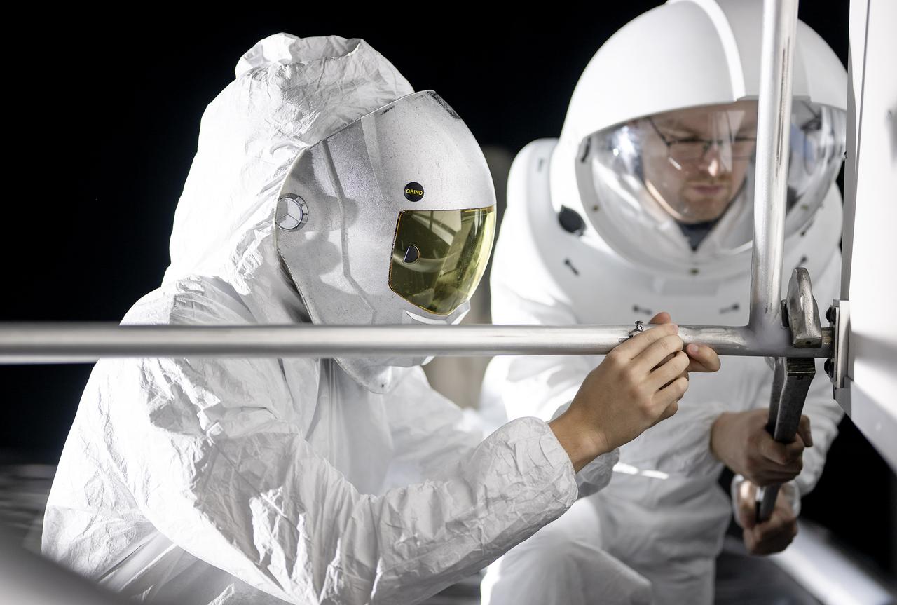
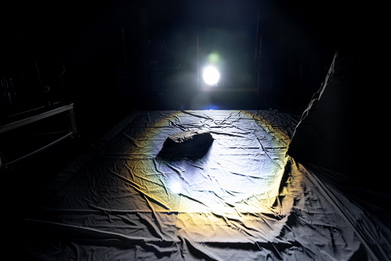
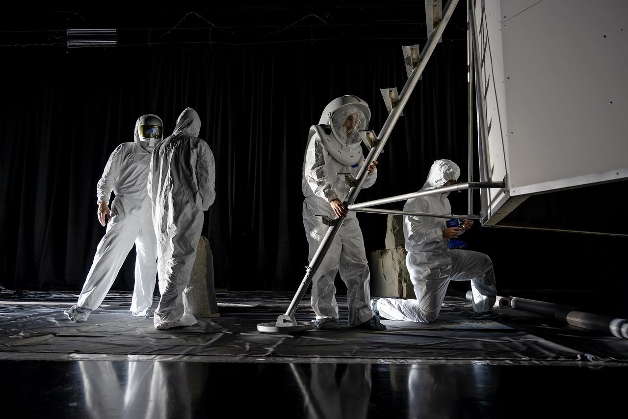
These photos show how teams at NASA’s Marshall Space Flight Center in Huntsville, Alabama, are using the Flat Floor Facility (Building 4619) to understand the lunar lighting environment in preparation for the Artemis III crewed lunar landing mission, slated for 2027. The Flat Floor Facility is an air-bearing floor, providing full-scale simulation capabilities for lunar surface systems by simulating zero gravity in two dimensions. Wearing low-fidelity materials, test engineers can understand how the extreme lighting of the Moon’s South Pole could affect surface operations during Artemis III. High-intensity lights are positioned at a low angle to replicate the strong shadows that are cast across the lunar South Pole by the Sun. Data and analysis from testing at NASA Marshall are improving models Artemis astronauts will use in preparation for lander and surface operations on the Moon during Artemis III. Testing in the facility is also helping cross-agency teams evaluate various tools astronauts may use. NASA Marshall manages the Human Landing System (HLS) Program. For more information, contact NASA Marshall’s Office of Communications at 256-544-0034.
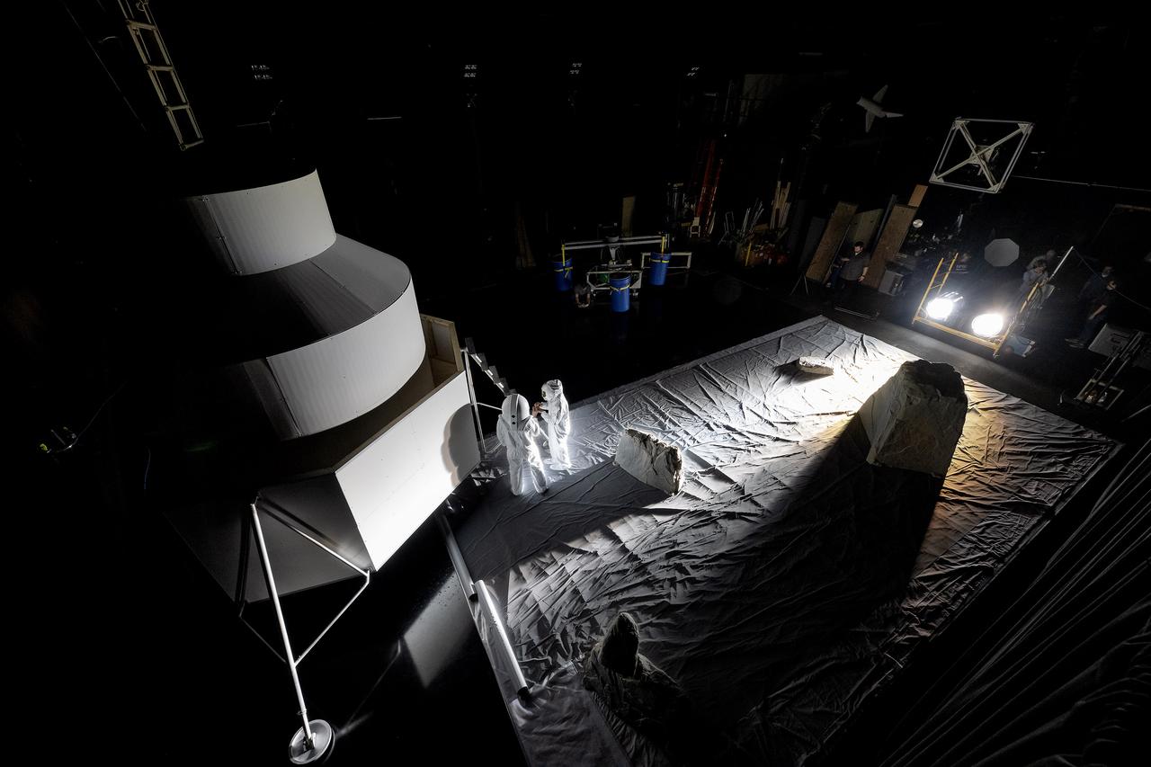
These photos show how teams at NASA’s Marshall Space Flight Center in Huntsville, Alabama, are using the Flat Floor Facility (Building 4619) to understand the lunar lighting environment in preparation for the Artemis III crewed lunar landing mission, slated for 2027. The Flat Floor Facility is an air-bearing floor, providing full-scale simulation capabilities for lunar surface systems by simulating zero gravity in two dimensions. Wearing low-fidelity materials, test engineers can understand how the extreme lighting of the Moon’s South Pole could affect surface operations during Artemis III. High-intensity lights are positioned at a low angle to replicate the strong shadows that are cast across the lunar South Pole by the Sun. Data and analysis from testing at NASA Marshall are improving models Artemis astronauts will use in preparation for lander and surface operations on the Moon during Artemis III. Testing in the facility is also helping cross-agency teams evaluate various tools astronauts may use. NASA Marshall manages the Human Landing System (HLS) Program. For more information, contact NASA Marshall’s Office of Communications at 256-544-0034.
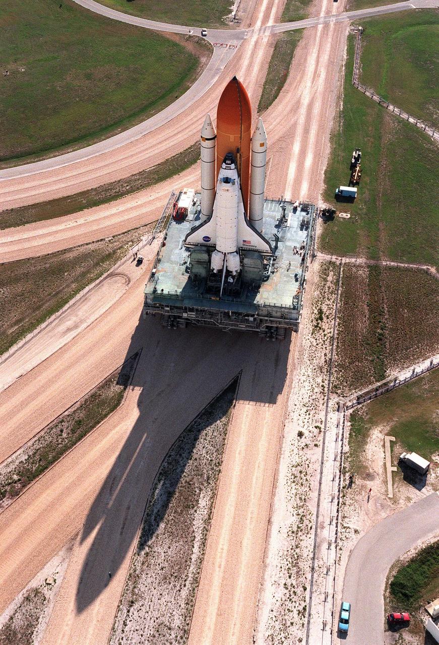
KENNEDY SPACE CENTER, FLA. -- Casting a giant shadow across the crawlerway, a crawler transporter slowly maneuvers Space Shuttle Discovery, with its external tank and solid rocket boosters, toward High Bay 1 of the Vehicle Assembly Building to repair damage to the external tank's foam insulation caused by hail. The necessary repair work could not be performed at Pad 39B due to limited access to the damaged areas. The work is expected to take two to three days, allowing Discovery to roll back to the pad by midweek for launch of mission STS-96, the 94th launch in the Space Shuttle Program. This is only the 13th time since 1981 that a Shuttle has had to roll back from the pad. Liftoff will occur no earlier than May 27. STS-96 is a logistics and resupply mission for the International Space Station, carrying such payloads as a Russian crane, the Strela; a U.S.-built crane; the Spacehab Oceaneering Space System Box (SHOSS), a logistics items carrier; and STARSHINE, a student-shared experiment
These photos show how teams at NASA’s Marshall Space Flight Center in Huntsville, Alabama, are using the Flat Floor Facility (Building 4619) to understand the lunar lighting environment in preparation for the Artemis III crewed lunar landing mission, slated for 2027. The Flat Floor Facility is an air-bearing floor, providing full-scale simulation capabilities for lunar surface systems by simulating zero gravity in two dimensions. Wearing low-fidelity materials, test engineers can understand how the extreme lighting of the Moon’s South Pole could affect surface operations during Artemis III. High-intensity lights are positioned at a low angle to replicate the strong shadows that are cast across the lunar South Pole by the Sun. Data and analysis from testing at NASA Marshall are improving models Artemis astronauts will use in preparation for lander and surface operations on the Moon during Artemis III. Testing in the facility is also helping cross-agency teams evaluate various tools astronauts may use. NASA Marshall manages the Human Landing System (HLS) Program. For more information, contact NASA Marshall’s Office of Communications at 256-544-0034.
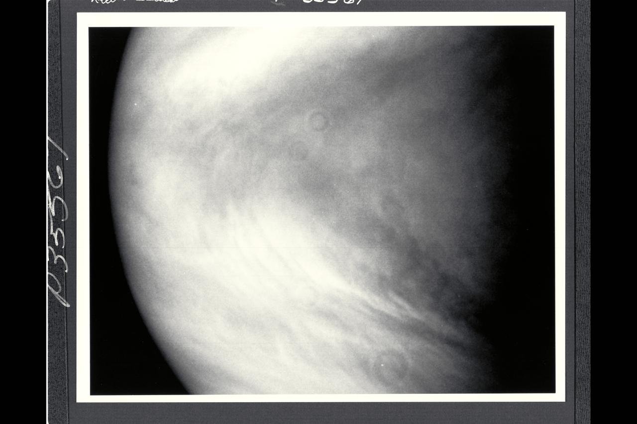
Range : 1 million miles (1.63 million km) This image of the planet Venus was taken by NASA's Galileo spacecraft shortly befor 10pm PST when the space craft was directly above Venus' equator. This is the 66th of more than 80 Venus images Galileo was programmed to take and record during its Venus flyby. In the picture, cloud features as small as 25 miles (40 km) can be seen. Patches of waves and convective clouds are superimpposed on the swirl of the planet's broad weather patterns, marked by the dark chevron at the center. North is at the top. The several ring-shaped shadows are blemishes, not planetary features. The spacecraft imaging system has a 1500-mm, f/8.5 reflecting telescope; the exposure time was 1/40 second. The image was taken through the violet filter (0.41 micron.). It was produced by the imaging system in digital form, as a set of numbers representing the brightness perceived in each of the 640,000 picture elements defined on the solid-state plate, called a charged-coupled-device or CCD, on which the image was focused.
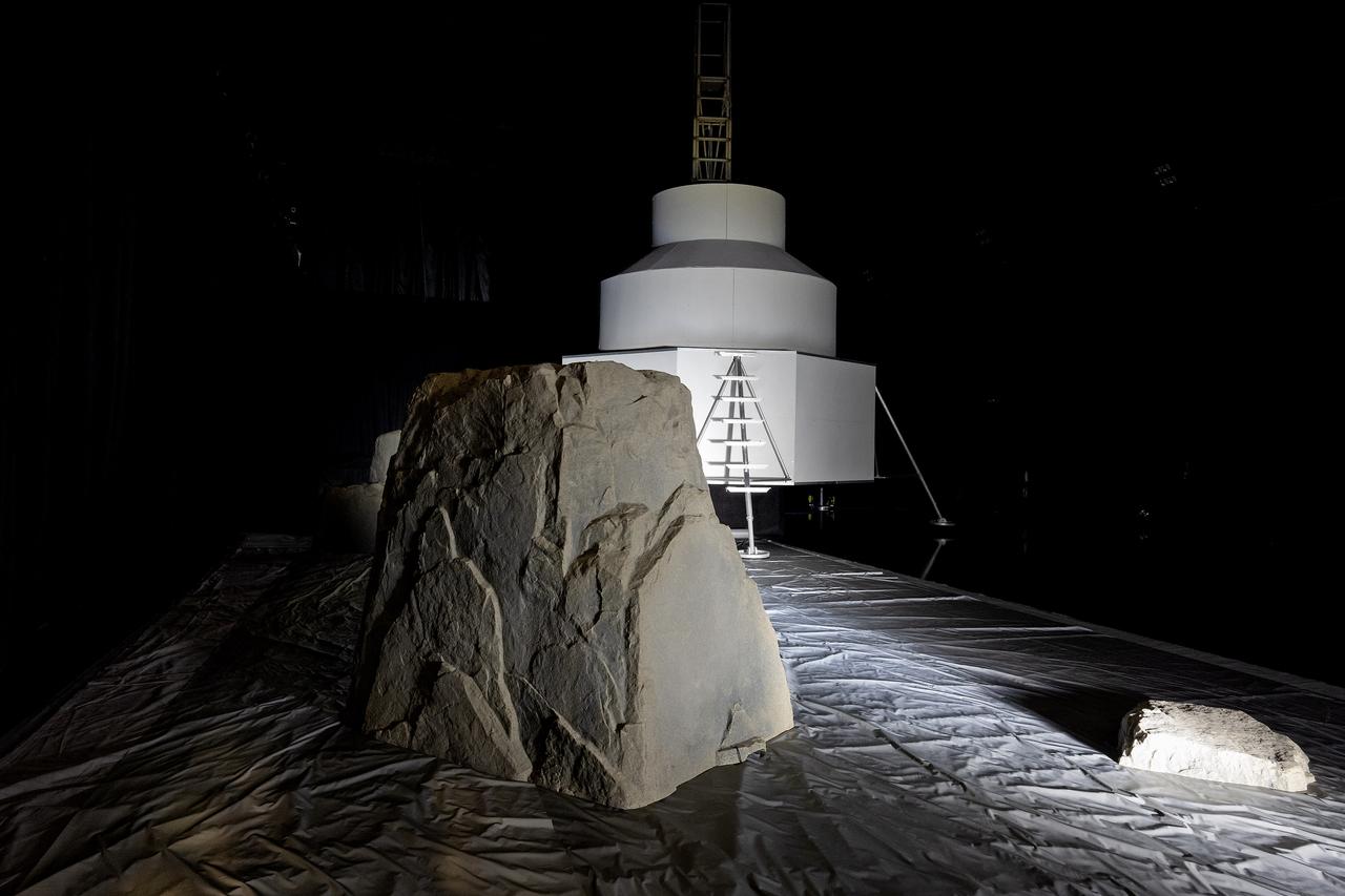
These photos show how teams at NASA’s Marshall Space Flight Center in Huntsville, Alabama, are using the Flat Floor Facility (Building 4619) to understand the lunar lighting environment in preparation for the Artemis III crewed lunar landing mission, slated for 2027. The Flat Floor Facility is an air-bearing floor, providing full-scale simulation capabilities for lunar surface systems by simulating zero gravity in two dimensions. Wearing low-fidelity materials, test engineers can understand how the extreme lighting of the Moon’s South Pole could affect surface operations during Artemis III. High-intensity lights are positioned at a low angle to replicate the strong shadows that are cast across the lunar South Pole by the Sun. Data and analysis from testing at NASA Marshall are improving models Artemis astronauts will use in preparation for lander and surface operations on the Moon during Artemis III. Testing in the facility is also helping cross-agency teams evaluate various tools astronauts may use. NASA Marshall manages the Human Landing System (HLS) Program. For more information, contact NASA Marshall’s Office of Communications at 256-544-0034.
KENNEDY SPACE CENTER, FLA. - At NASA’s Kennedy Space Center, Space Shuttle Discovery, atop the Mobile Launcher Platform (MLP), casts a shadow on the crawlerway as it makes its way east to Launch Complex 39B close to sunset. In the background is the Vehicle Assembly Building (VAB) where Discovery began the rollout at 2:04 p.m. EDT. The rollout marks a major milestone in the Space Shuttle Program’s Return to Flight. The MLP is moved by the Crawler-Transporter underneath, which stands 20 feet high, 131 feet long and 114 feet wide. It moves on eight tracks, each containing 57 shoes, or cleats, weighing one ton each. Loaded with the Space Shuttle, the Crawler can move at a maximum speed of approximately 1 mile an hour. A leveling system in the Crawler keeps the Shuttle vertical while negotiating the 5 percent grade leading to the top of the launch pad. Launch of Discovery on its Return to Flight mission, STS-114, is targeted for May 15 with a launch window that extends to June 3. During its 12-day mission, Discovery’s seven-person crew will test new hardware and techniques to improve Shuttle safety, as well as deliver supplies to the International Space Station.
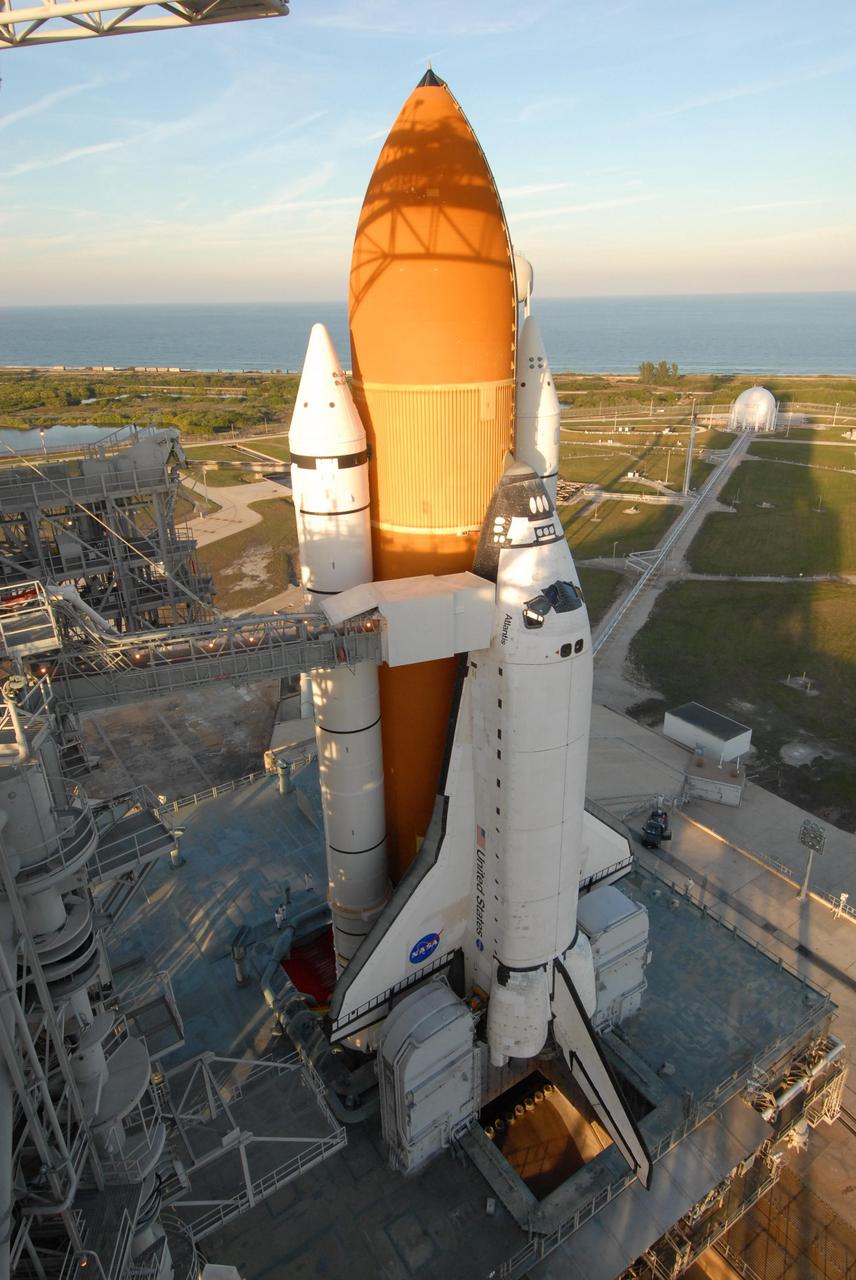
KENNEDY SPACE CENTER, FLA. -- Shadows spill across space shuttle Atlantis, still poised on the pad after its launch on mission STS-122 was postponed Thursday. In the background is the Atlantic Ocean. Shuttle program managers decided at 9:56 a.m. to postpone the launch because of an issue with a fuel cut-off sensor system inside the external fuel tank. This is one of several systems that protect the shuttle's main engines by triggering their shut down if fuel runs unexpectedly low. During countdown activities this morning, two sensors failed a routine prelaunch check. There are four engine cut-off, or ECO, sensors inside the liquid hydrogen section of the tank, and Launch Commit Criteria require three of the four sensor systems to be functioning properly. The tank's liquid oxygen and liquid hydrogen was drained from the tank, and preparations will begin for a possible launch attempt Friday. NASA's launch rules have a preplanned procedure that states in the case of ECO sensor system failure, engineers need to drain the tank and verify all the sensors are working as they go dry. Atlantis carries the Columbus Laboratory, the European Space Agency's largest contribution to the construction of the space station. When permanently attached to Node 2, the laboratory will carry out experiments in materials science, fluid physics and biosciences, as well as perform a number of technological applications, in a microgravity environment. Photo credit: NASA/George Shelton
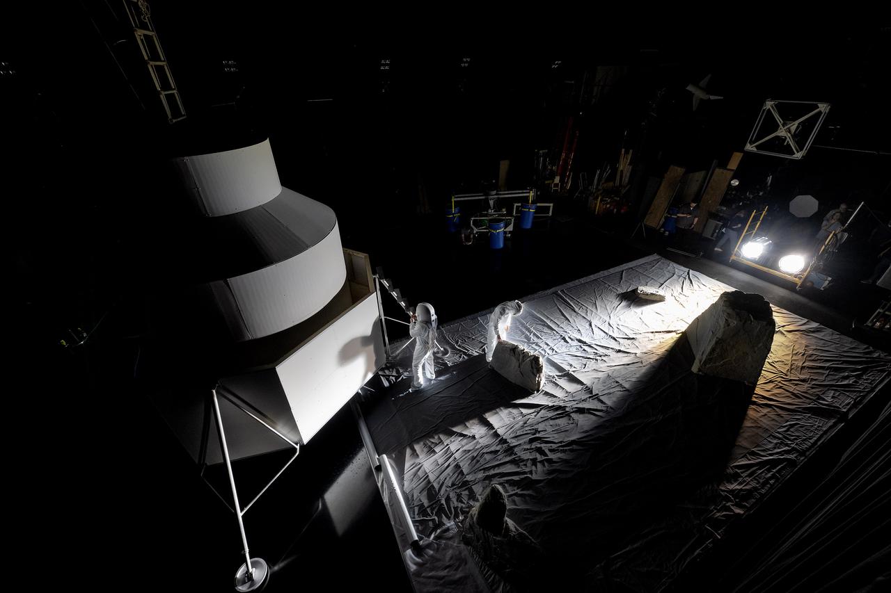
These photos show how teams at NASA’s Marshall Space Flight Center in Huntsville, Alabama, are using the Flat Floor Facility (Building 4619) to understand the lunar lighting environment in preparation for the Artemis III crewed lunar landing mission, slated for 2027. The Flat Floor Facility is an air-bearing floor, providing full-scale simulation capabilities for lunar surface systems by simulating zero gravity in two dimensions. Wearing low-fidelity materials, test engineers can understand how the extreme lighting of the Moon’s South Pole could affect surface operations during Artemis III. High-intensity lights are positioned at a low angle to replicate the strong shadows that are cast across the lunar South Pole by the Sun. Data and analysis from testing at NASA Marshall are improving models Artemis astronauts will use in preparation for lander and surface operations on the Moon during Artemis III. Testing in the facility is also helping cross-agency teams evaluate various tools astronauts may use. NASA Marshall manages the Human Landing System (HLS) Program. For more information, contact NASA Marshall’s Office of Communications at 256-544-0034.

These photos show how teams at NASA’s Marshall Space Flight Center in Huntsville, Alabama, are using the Flat Floor Facility (Building 4619) to understand the lunar lighting environment in preparation for the Artemis III crewed lunar landing mission, slated for 2027. The Flat Floor Facility is an air-bearing floor, providing full-scale simulation capabilities for lunar surface systems by simulating zero gravity in two dimensions. Wearing low-fidelity materials, test engineers can understand how the extreme lighting of the Moon’s South Pole could affect surface operations during Artemis III. High-intensity lights are positioned at a low angle to replicate the strong shadows that are cast across the lunar South Pole by the Sun. Data and analysis from testing at NASA Marshall are improving models Artemis astronauts will use in preparation for lander and surface operations on the Moon during Artemis III. Testing in the facility is also helping cross-agency teams evaluate various tools astronauts may use. NASA Marshall manages the Human Landing System (HLS) Program. For more information, contact NASA Marshall’s Office of Communications at 256-544-0034.
These photos show how teams at NASA’s Marshall Space Flight Center in Huntsville, Alabama, are using the Flat Floor Facility (Building 4619) to understand the lunar lighting environment in preparation for the Artemis III crewed lunar landing mission, slated for 2027. The Flat Floor Facility is an air-bearing floor, providing full-scale simulation capabilities for lunar surface systems by simulating zero gravity in two dimensions. Wearing low-fidelity materials, test engineers can understand how the extreme lighting of the Moon’s South Pole could affect surface operations during Artemis III. High-intensity lights are positioned at a low angle to replicate the strong shadows that are cast across the lunar South Pole by the Sun. Data and analysis from testing at NASA Marshall are improving models Artemis astronauts will use in preparation for lander and surface operations on the Moon during Artemis III. Testing in the facility is also helping cross-agency teams evaluate various tools astronauts may use. NASA Marshall manages the Human Landing System (HLS) Program. For more information, contact NASA Marshall’s Office of Communications at 256-544-0034.
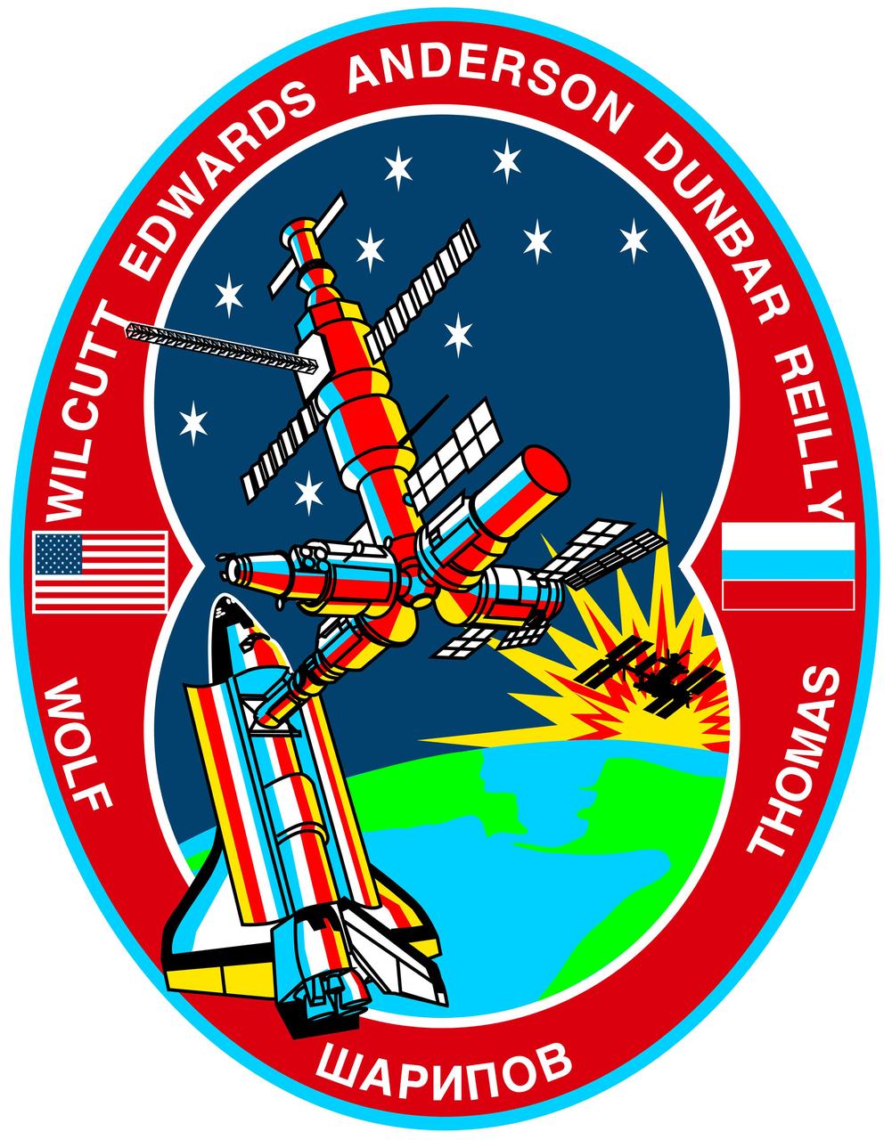
In the STS-89 crew insignia, the link between the United States and Russia is symbolically represented by the Space Shuttle Endeavour and Russia's Mir Space Station orbiting above the Bering Strait between Siberia and Alaska. The success of the joint United States-Russian missions is depicted by the Space Shuttle and Mir colored by the rising sun in the background. A shadowed representation of the International Space Station (ISS) rising with the sun represents the future program for which the Shuttle-Mir missions are prototypes. The inside rim of the insignia describes the outline of the number eight representing STS-89 as the eighth Shuttle/Mir docking mission. The nine stars represent the nine joint missions to be flown of the program and when combined with the number eight in the rim, reflect the mission number. The nine stars also symbolize the children of the crew members who will be the future beneficiaries of the joint development work of the space programs of the two countries. Along the rim are the crew members' names with David A. Wolf's name on the left and Andrew S. W. Thomas' name on the right, the returning and upgoing cosmonaut guest researcher crew members. In between and at the bottom is the name of Salizan S. Sharipov, payload specialist representing Russian Space Agency (RSA), in Cyrillic alphabet. The other crew members are Terrence W. Wilcutt, commander; Joe F. Edwards, Jr., pilot; and mission specialists Michael P. Anderson, Bonnie J. Dunbar, and James F. Reilly. The red, white and blue of the rim reflect the colors of the American and Russian flags which are also represented in the rim on either side of the joined spacecraft.
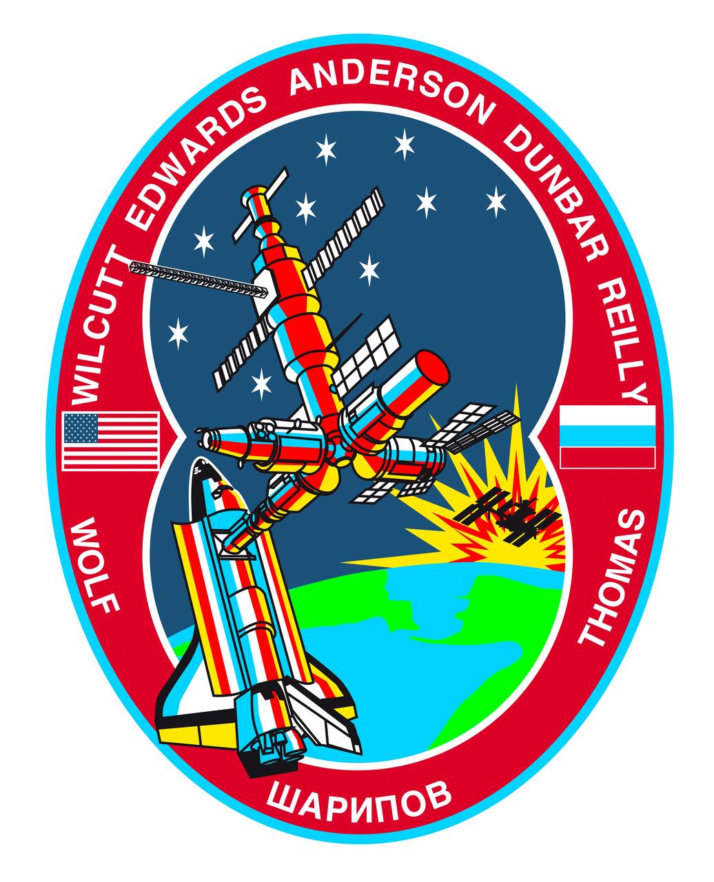
STS089-S-001 (October 1997) --- The link between the United States and Russia is symbolically represented by the space shuttle Endeavour and Russia?s Mir Space Station orbiting above the Bering Strait between Siberia and Alaska. The success of the joint United States-Russian missions is depicted by the space shuttle and Mir colored by the rising sun in the background. A shadowed representation of the International Space Station (ISS) rising with the sun represents the future program for which the Shuttle-Mir missions are prototypes. The inside rim of the insignia describes the outline of the number eight representing STS-89 as the eighth Shuttle/Mir docking mission. The nine stars represent the nine joint missions to be flown of the program and ? when combined with the number eight in the rim -- reflect the mission number. The nine stars also symbolize the children of the crew members who will be the future beneficiaries of the joint development work of the space programs of the two countries. Along the rim are the crew members? names with David A. Wolf?s name on the left and Andrew S. W. Thomas? name on the right, the returning and upgoing cosmonaut guest researcher crew members. In between and at the bottom is the name of Salizan S. Sharipov, mission specialist representing Russian Space Agency (RSA), in Cyrillic alphabet. The other crew members are Terrence W. Wilcutt, commander; Joe F. Edwards Jr., pilot; and mission specialists Michael P. Anderson, Bonnie J. Dunbar, and James F. Reilly. The red, white and blue of the rim reflect the colors of the American and Russian flags which are also represented in the rim on either side of the joined spacecraft. The NASA insignia design for space shuttle flights is reserved for use by the astronauts and for other official use as the NASA Administrator may authorize. Public availability has been approved only in the forms of illustrations by the various news media. When and if there is any change in this policy, which is not anticipated, the change will be publicly announced. Photo credit: NASA

iss069-e-089946_lrg (09/19/2023) --- An astronaut aboard the International Space Station took this photograph of the rugged landscape of the Aladaghlar Mountains in northwestern Iran. Ridges cast shadows in the valleys and other low elevation areas, creating a three-dimensional appearance. Human alterations to the landscape are most evident in riverbeds, where the even topography is easier to build on and navigate. Natural processes over millions of years have folded rock layers of various compositions and colors into the curved patterns seen here. These folds are produced by tectonic forces operating along the convergent plate boundary of the Arabia and Eurasia plates. The convergence of these tectonic plates causes uplift, folding, and deformation of the colorful rock layers, and subsequent erosion exposes them. On the left side of this photo, the Qezel Ozan River, a major river in northern Iran, cuts across the landscape. Agricultural fields are visible along the riverbanks tucked between the mountains. The Qezel Ozan also intersects the Zanjan-Tabriz freeway (Freeway 2), a major thoroughfare built on a dried riverbed connecting the cities of Tehran and Tabriz. Astronaut photograph ISS069-E-89946 was acquired on September 19, 2023, with a Nikon D5 digital camera using a focal length of 400 millimeters. The image was provided by the ISS Crew Earth Observations Facility and the Earth Science and Remote Sensing Unit at Johnson Space Center. The image was taken by a member of the Expedition 69 crew. It has been cropped and enhanced to improve contrast, and lens artifacts have been removed. The International Space Station Program supports the laboratory as part of the ISS National Lab to help astronauts take pictures of Earth that will be of the greatest value to scientists and the public and to make those images freely available on the Internet. Additional images taken by astronauts and cosmonauts can be viewed at the NASA/JSC Gateway to Astronaut Photography of Earth. Caption by Sara Schmidt, GeoControl Systems, JETS II Contract at NASA-JSC and Andrea Wenzel, Jacobs-JETS II Contract at NASA-JSC.
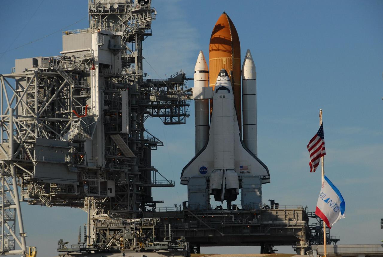
KENNEDY SPACE CENTER, FLA. -- In the late afternoon shadows, space shuttle Atlantis is still poised on the pad after its launch on mission STS-122 was postponed Thursday. It sits atop the mobile launcher platform. Shuttle program managers decided at 9:56 a.m. to postpone the launch because of an issue with a fuel cut-off sensor system inside the external fuel tank. This is one of several systems that protect the shuttle's main engines by triggering their shut down if fuel runs unexpectedly low. During countdown activities this morning, two sensors failed a routine prelaunch check. There are four engine cut-off, or ECO, sensors inside the liquid hydrogen section of the tank, and Launch Commit Criteria require three of the four sensor systems to be functioning properly. The tank's liquid oxygen and liquid hydrogen was drained from the tank, and preparations will begin for a possible launch attempt Friday. NASA's launch rules have a preplanned procedure that states in the case of ECO sensor system failure, engineers need to drain the tank and verify all the sensors are working as they go dry. Atlantis carries the Columbus Laboratory, the European Space Agency's largest contribution to the construction of the space station. When permanently attached to Node 2, the laboratory will carry out experiments in materials science, fluid physics and biosciences, as well as perform a number of technological applications, in a microgravity environment. Photo credit: NASA/George Shelton
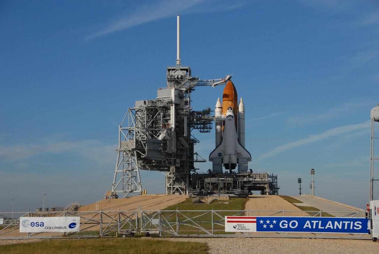
KENNEDY SPACE CENTER, FLA. -- Shadows spill across space shuttle Atlantis, still poised on the pad after its launch on mission STS-122 was postponed Thursday. It sits atop the mobile launcher platform. Shuttle program managers decided at 9:56 a.m. to postpone the launch because of an issue with a fuel cut-off sensor system inside the external fuel tank. This is one of several systems that protect the shuttle's main engines by triggering their shut down if fuel runs unexpectedly low. During countdown activities this morning, two sensors failed a routine prelaunch check. There are four engine cut-off, or ECO, sensors inside the liquid hydrogen section of the tank, and Launch Commit Criteria require three of the four sensor systems to be functioning properly. The tank's liquid oxygen and liquid hydrogen was drained from the tank, and preparations will begin for a possible launch attempt Friday. NASA's launch rules have a preplanned procedure that states in the case of ECO sensor system failure, engineers need to drain the tank and verify all the sensors are working as they go dry. Atlantis carries the Columbus Laboratory, the European Space Agency's largest contribution to the construction of the space station. When permanently attached to Node 2, the laboratory will carry out experiments in materials science, fluid physics and biosciences, as well as perform a number of technological applications, in a microgravity environment. Photo credit: NASA/George Shelton
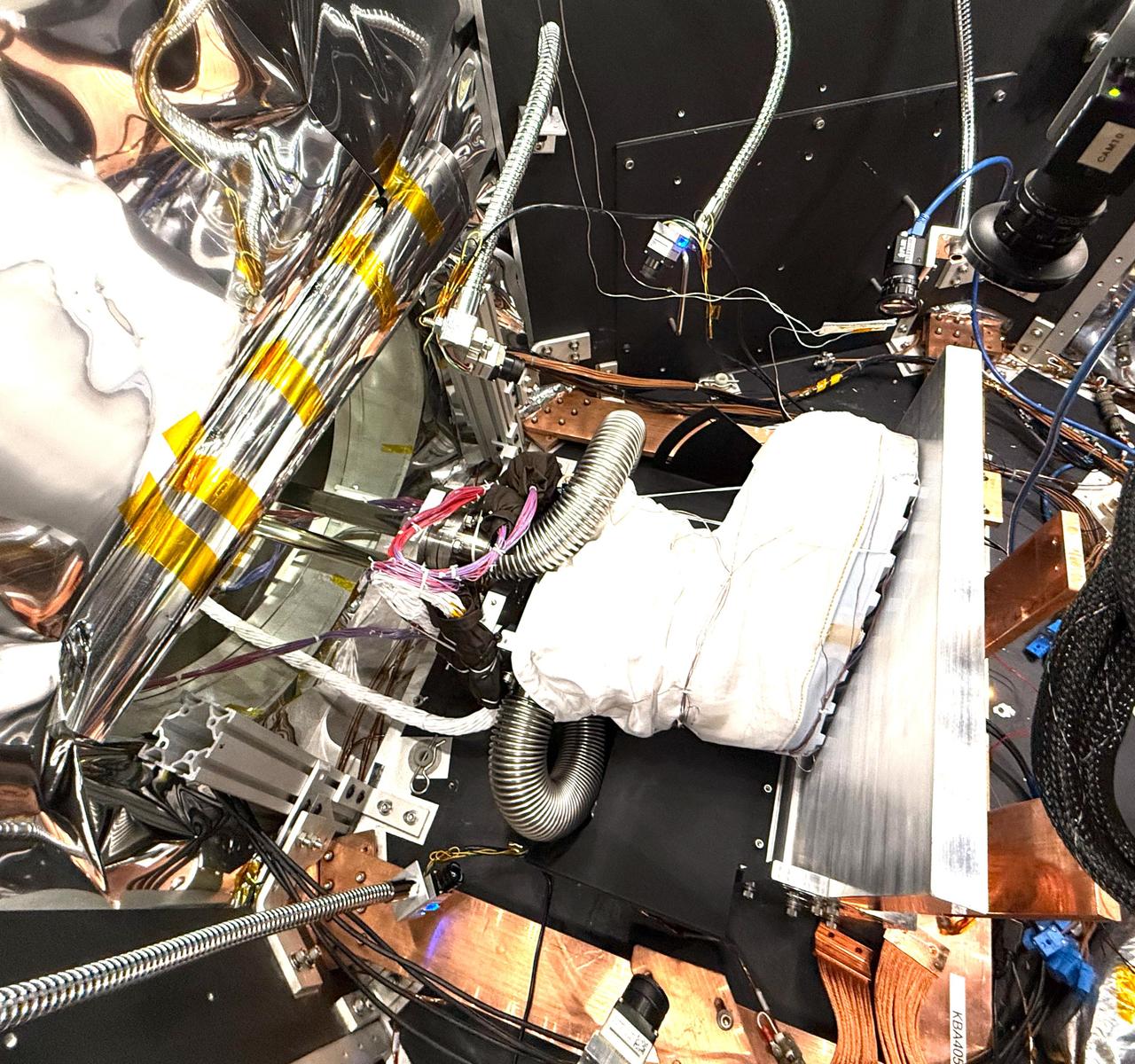
A boot that's part of a NASA lunar surface spacesuit prototype is readied for testing inside a thermal vacuum chamber called CITADEL at the agency's Jet Propulsion Laboratory in Southern California on Nov. 8, 2024. The thick aluminum plate at right stands in for the frigid surface of the lunar South Pole, where Artemis III astronauts will confront conditions more extreme than any previously experienced by humans. Built to prepare potential future robotic spacecraft for the frosty, low-pressure conditions on ocean worlds like Jupiter's frozen moon Europa, CITADEL (Cryogenic Ice Testing, Acquisition Development, and Excavation Laboratory) has also proven key to evaluating how astronaut gloves and boots hold up in extraordinary cold. It can reach temperatures as low as low as minus 370 degrees Fahrenheit (minus 223 degrees Celsius), approximating conditions in permanently shadowed regions that astronauts will explore. Figure A, showing the outer boot sole, was taken from inside CITADEL on Nov. 13, 2024. The boot is positioned in a load lock, one of four small drawer-like chambers through which test materials are inserted into the larger chamber. Initiated by the Extravehicular Activity and Human Surface Mobility Program at NASA's Johnson Space Center, the boot testing took place from October 2024 to January 2025. The boot is part of a NASA spacesuit called the Exploration Extravehicular Mobility Unit, or xEMU. Results haven't yet been fully analyzed. In addition to spotting vulnerabilities with existing suits, the experiments are intended to help NASA develop this unique test capability and prepare criteria for standardized, repeatable, and inexpensive test methods for the next-generation lunar suit being built by Axiom Space. https://photojournal.jpl.nasa.gov/catalog/PIA26592
KENNEDY SPACE CENTER, FLA. -- In the late afternoon shadows, space shuttle Atlantis is still poised on the pad after its launch on mission STS-122 was postponed Thursday. It sits atop the mobile launcher platform. Shuttle program managers decided at 9:56 a.m. to postpone the launch because of an issue with a fuel cut-off sensor system inside the external fuel tank. This is one of several systems that protect the shuttle's main engines by triggering their shut down if fuel runs unexpectedly low. During countdown activities this morning, two sensors failed a routine prelaunch check. There are four engine cut-off, or ECO, sensors inside the liquid hydrogen section of the tank, and Launch Commit Criteria require three of the four sensor systems to be functioning properly. The tank's liquid oxygen and liquid hydrogen was drained from the tank, and preparations will begin for a possible launch attempt Friday. NASA's launch rules have a preplanned procedure that states in the case of ECO sensor system failure, engineers need to drain the tank and verify all the sensors are working as they go dry. Atlantis carries the Columbus Laboratory, the European Space Agency's largest contribution to the construction of the space station. When permanently attached to Node 2, the laboratory will carry out experiments in materials science, fluid physics and biosciences, as well as perform a number of technological applications, in a microgravity environment. Photo credit: NASA/George Shelton
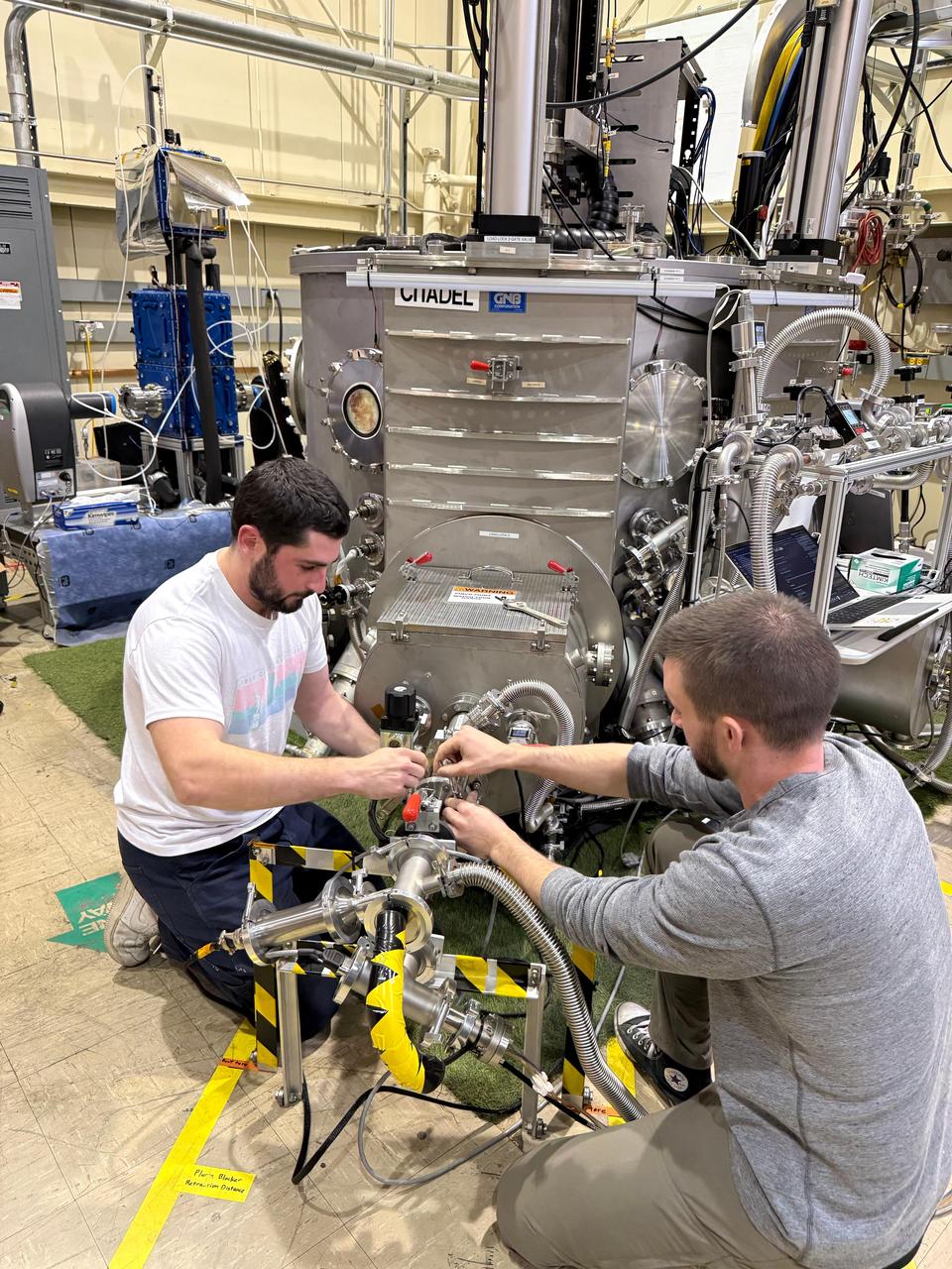
Robotics technologist Brendan Chamberlain-Simon, left, of NASA's Jet Propulsion Laboratory and spacesuit engineer Zach Fester of the agency's Johnson Space Center adjust a thermal vacuum chamber called CITADEL at JPL on Nov. 12, 2024, before testing an astronaut boot inside the chamber. Built to prepare potential robotic explorers for the frosty, low-pressure conditions on ocean worlds like Jupiter's frozen moon Europa, CITADEL (Cryogenic Ice Testing, Acquisition Development, and Excavation Laboratory) has also proven key to evaluating how astronaut gloves and boots hold up in extraordinary cold. It can reach temperatures as low as low as minus 370 degrees Fahrenheit (minus 223 degrees Celsius), approximating extreme conditions Artemis III astronauts will confront in permanently shadowed regions of the lunar South Pole. The boot testing was initiated by the Extravehicular Activity and Human Surface Mobility Program at NASA Johnson and took place from October 2024 to January 2025. The boot is part of a NASA spacesuit called the Exploration Extravehicular Mobility Unit, or xEMU. Test results haven't yet been fully analyzed. In addition to spotting vulnerabilities with existing suits, the experiments are intended to help NASA develop this unique test capability and prepare criteria for standardized, repeatable, and inexpensive test methods for the next-generation lunar suit being built by Axiom Space. https://photojournal.jpl.nasa.gov/catalog/PIA26593
KENNEDY SPACE CENTER, FLA. -- In the late afternoon shadows, space shuttle Atlantis is still poised on the pad after its launch on mission STS-122 was postponed Thursday. It sits atop the mobile launcher platform. At left is seen the rotating service structure, which was rolled away for the launch. Shuttle program managers decided at 9:56 a.m. to postpone the launch because of an issue with a fuel cut-off sensor system inside the external fuel tank. This is one of several systems that protect the shuttle's main engines by triggering their shut down if fuel runs unexpectedly low. During countdown activities this morning, two sensors failed a routine prelaunch check. There are four engine cut-off, or ECO, sensors inside the liquid hydrogen section of the tank, and Launch Commit Criteria require three of the four sensor systems to be functioning properly. The tank's liquid oxygen and liquid hydrogen was drained from the tank, and preparations will begin for a possible launch attempt Friday. NASA's launch rules have a preplanned procedure that states in the case of ECO sensor system failure, engineers need to drain the tank and verify all the sensors are working as they go dry. Atlantis carries the Columbus Laboratory, the European Space Agency's largest contribution to the construction of the space station. When permanently attached to Node 2, the laboratory will carry out experiments in materials science, fluid physics and biosciences, as well as perform a number of technological applications, in a microgravity environment. Photo credit: NASA/George Shelton
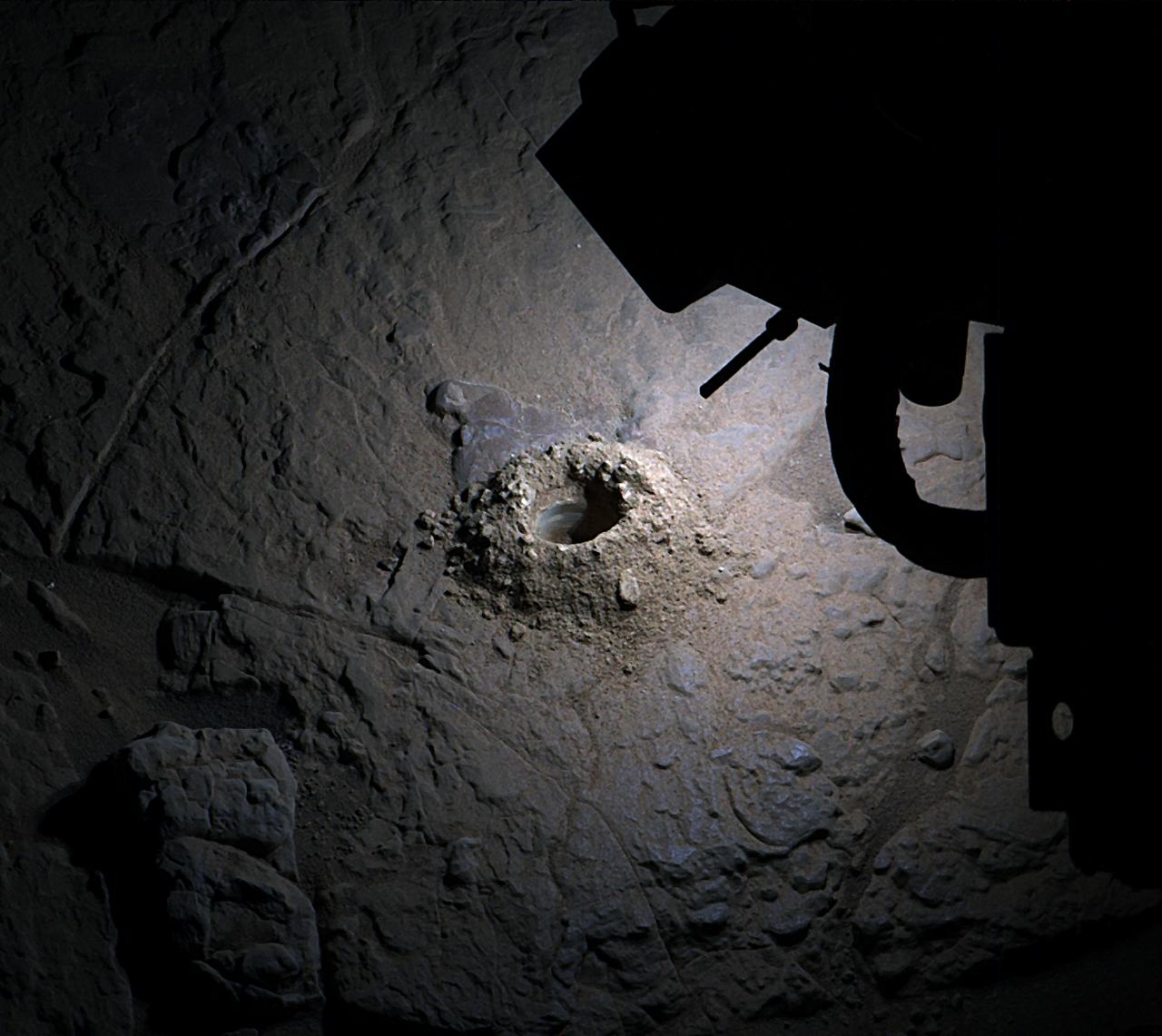
NASA’s Curiosity Mars rover used LED lights on the end of its robotic arm to create this rare nighttime view of the Red Planet’s surface on Dec. 6, 2025, the 4,740th Martian day, or sol, of the rover’s mission. The LED lights are part of the Mars Hand Lens Imager, or MAHLI, a camera on the end of Curiosity’s robotic arm. The image was captured by the Mast Camera, or Mastcam, on the rover’s mast, or “head.” On occasion, scientists have used MAHLI’s LED lights to illuminate areas deep in shadow during the day, such as the insides of drill holes and the inlet tubes leading to instruments in the rover’s belly. Much earlier in the mission, the Curiosity team used these LEDs at night to look for layering or other features in drill hole walls that would help them understand a rock’s composition. Since the mission changed its drilling method, the drill holes have come out too rough and dusty to see any such details. After drilling a rock target nicknamed “Nevado Sajama” on Nov. 13, 2025 (Sol 4,718), the team noticed the drill hole walls were smooth enough to try looking for layers and decided to try illuminating the drill hole at night. This drill hole was made during Curiosity’s exploration of a region full of geologic formations called boxwork, which crisscross the surface for miles and look like giant spiderwebs when viewed from space. Curiosity was built by NASA’s Jet Propulsion Laboratory, which is managed by Caltech in Pasadena, California. JPL leads the mission on behalf of NASA’s Science Mission Directorate in Washington as part of NASA’s Mars Exploration Program portfolio. Malin Space Science Systems in San Diego built and operates both Mastcam and MAHLI. To learn more about Curiosity, visit: science.nasa.gov/mission/msl-curiosity
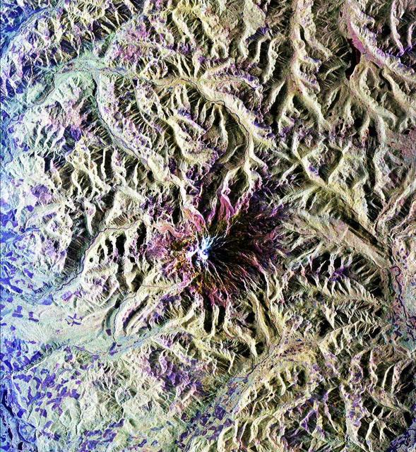
This is a radar image of Mount Rainier in Washington state. The volcano last erupted about 150 years ago and numerous large floods and debris flows have originated on its slopes during the last century. Today the volcano is heavily mantled with glaciers and snowfields. More than 100,000 people live on young volcanic mudflows less than 10,000 years old and, consequently, are within the range of future, devastating mudslides. This image was acquired by the Spaceborne Imaging Radar-C and X-band Synthetic Aperture Radar (SIR-C/X-SAR) aboard the space shuttle Endeavour on its 20th orbit on October 1, 1994. The area shown in the image is approximately 59 kilometers by 60 kilometers (36.5 miles by 37 miles). North is toward the top left of the image, which was composed by assigning red and green colors to the L-band, horizontally transmitted and vertically, and the L-band, horizontally transmitted and vertically received. Blue indicates the C-band, horizontally transmitted and vertically received. In addition to highlighting topographic slopes facing the space shuttle, SIR-C records rugged areas as brighter and smooth areas as darker. The scene was illuminated by the shuttle's radar from the northwest so that northwest-facing slopes are brighter and southeast-facing slopes are dark. Forested regions are pale green in color; clear cuts and bare ground are bluish or purple; ice is dark green and white. The round cone at the center of the image is the 14,435-foot (4,399-meter) active volcano, Mount Rainier. On the lower slopes is a zone of rock ridges and rubble (purple to reddish) above coniferous forests (in yellow/green). The western boundary of Mount Rainier National Park is seen as a transition from protected, old-growth forest to heavily logged private land, a mosaic of recent clear cuts (bright purple/blue) and partially regrown timber plantations (pale blue). The prominent river seen curving away from the mountain at the top of the image (to the northwest) is the White River, and the river leaving the mountain at the bottom right of the image (south) is the Nisqually River, which flows out of the Nisqually glacier on the mountain. The river leaving to the left of the mountain is the Carbon River, leading west and north toward heavily populated regions near Tacoma. The dark patch at the top right of the image is Bumping Lake. Other dark areas seen to the right of ridges throughout the image are radar shadow zones. Radar images can be used to study the volcanic structure and the surrounding regions with linear rock boundaries and faults. In addition, the recovery of forested lands from natural disasters and the success of reforestation programs can also be monitored. Ultimately this data may be used to study the advance and retreat of glaciers and other forces of global change. http://photojournal.jpl.nasa.gov/catalog/PIA01727
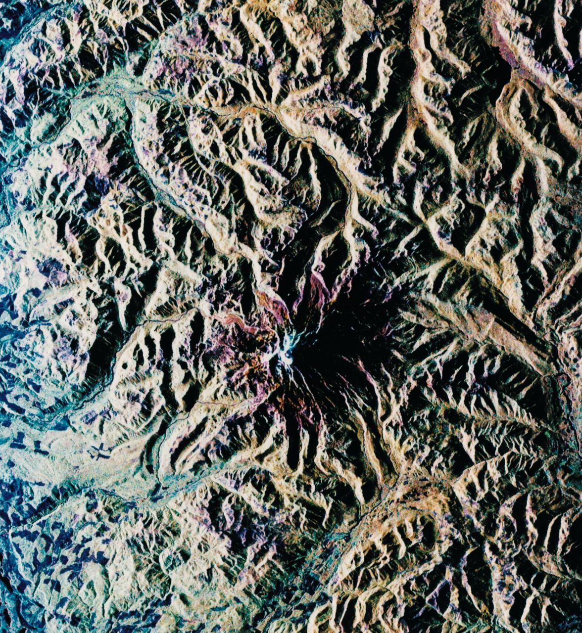
STS068-S-052 (3 October 1994) --- This is a radar image of Mount Rainier in Washington state. The volcano last erupted about 150 years ago and numerous large floods and debris flows have originated on its slopes during the last century. Today the volcano is heavily mantled with glaciers and snow fields. More than 100,000 people live on young volcanic mud flows less than 10,000 years old and, are within the range of future, devastating mud slides. This image was acquired by the Spaceborne Imaging Radar-C/X-Band Synthetic Aperture Radar (SIR-C/X-SAR) aboard the Space Shuttle Endeavour on its 20th orbit on October 1, 1994. The area shown in the image is approximately 59 by 60 kilometers (36.5 by 37 miles). North is toward the top left of the image, which was composed by assigning red and green colors to the L-Band, horizontally transmitted and vertically, and the L-Band, horizontally transmitted and vertically received. Blue indicates the C-Band, horizontally transmitted and vertically received. In addition to highlighting topographic slopes facing the Space Shuttle, SIR-C records rugged areas as brighter and smooth areas as darker. The scene was illuminated by the Shuttle's radar from the northwest so that northwest-facing slopes are brighter and southeast-facing slopes are dark. Forested regions are pale green in color, clear cuts and bare ground are bluish or purple; ice is dark green and white. The round cone at the center of the image is the 14,435 feet (4,399 meters) active volcano, Mount Rainier. On the lower slopes is a zone of rock ridges and rubble (purple to reddish) above coniferous forests (in yellow/green). The western boundary of Mount Rainier National Park is seen as a transition from protected, old-growth forest to heavily logged private land, a mosaic of recent clear cuts (bright purple/blue) and partially re-grown timber plantations (pale blue). The prominent river seen curving away from the mountain at the top of the image (to the northwest) is the White River, and the river leaving the mountain at the bottom right of the image (south) is the Nisqually River, which flows out of the Nisqually glacier on the mountain. The river leaving to the left of the mountain is the Carbon River, leading west and north toward heavily populated regions near Tacoma. The dark patch at the top right of the image is Bumping Lake. Other dark areas seen to the right of ridges throughout the image are radar shadow zones. Radar images can be used to study the volcanic structure and the surrounding regions with linear rock boundaries and faults. In addition, the recovery of forested lands from natural disasters and the success of re-forestation programs can also be monitored. Ultimately this data may be used to study the advance and retreat of glaciers and other forces of global change. Spaceborne Imaging Radar-C/X-Band Synthetic Aperture Radar (SIR-C/X-SAR) is part of NASA's Mission to Planet Earth. (P-44703)