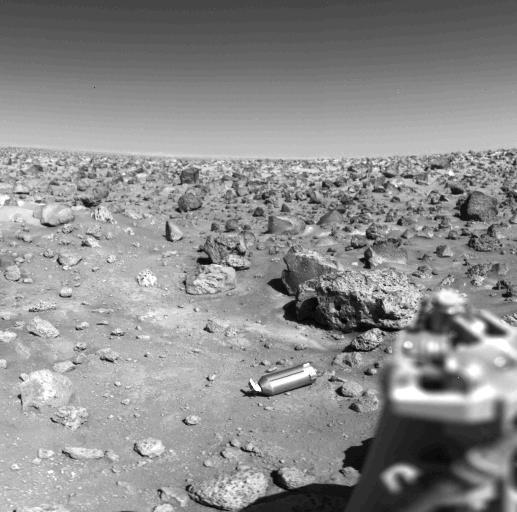
Ejected Shroud on the Martian Surface
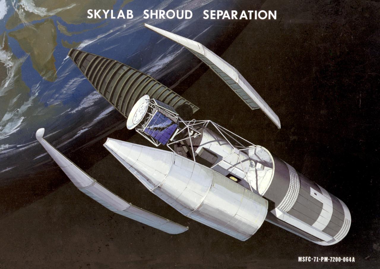
This artist's concept depicts the separation of the Skylab payload shroud. The payload shroud was both an environmental shield and an aerodynamic fairing. Attached to the forward end of the fixed airlock shroud, it protected the airlock, the docking adapter, and the solar observatory before and during launch. It also provided structural support for the solar observatory in the launch configuration. The payload shroud was jettisoned once Skylab reached orbit after separation of the S-II second stage of the Saturn V vehicle. Five major assemblies clustered together made up the orbiting space station called Skylab. The largest of these was the orbital workshop, that housed the crew quarters and a major experiment area. The airlock module, attached to the forward end of the workshop, enabled crewmembers to make excursions outside Skylab. The docking adapter, attached to the forward end of the airlock module, provided the docking port for the Apollo command and service module. The Apollo Telescope Mount was the first marned astronomical observatory designed for solar research from Earth orbit.
Space Power Facility at Plum Brook Station, RUAG Ariane 5 Shroud Separation Tests. GRC has the world's largest vacuum chamber in the world. This world class facility is host to many space launch vehicle systems tests from customer's in this country and from around the world. Shown here is the post test of a successful rocket shroud separation test. The shroud, or top of a rocket, is jettisoned into two halves with explosive charges to allow the payload to be exposed for deployment. The payload, often time is a satellite, would be sitting atop the center white section shown in the middle of the photo. This photo was taken from on top of the rocket holding the payload and both halves of the rocket shroud looking down at one of the shroud halves and the test crew at the bottom.
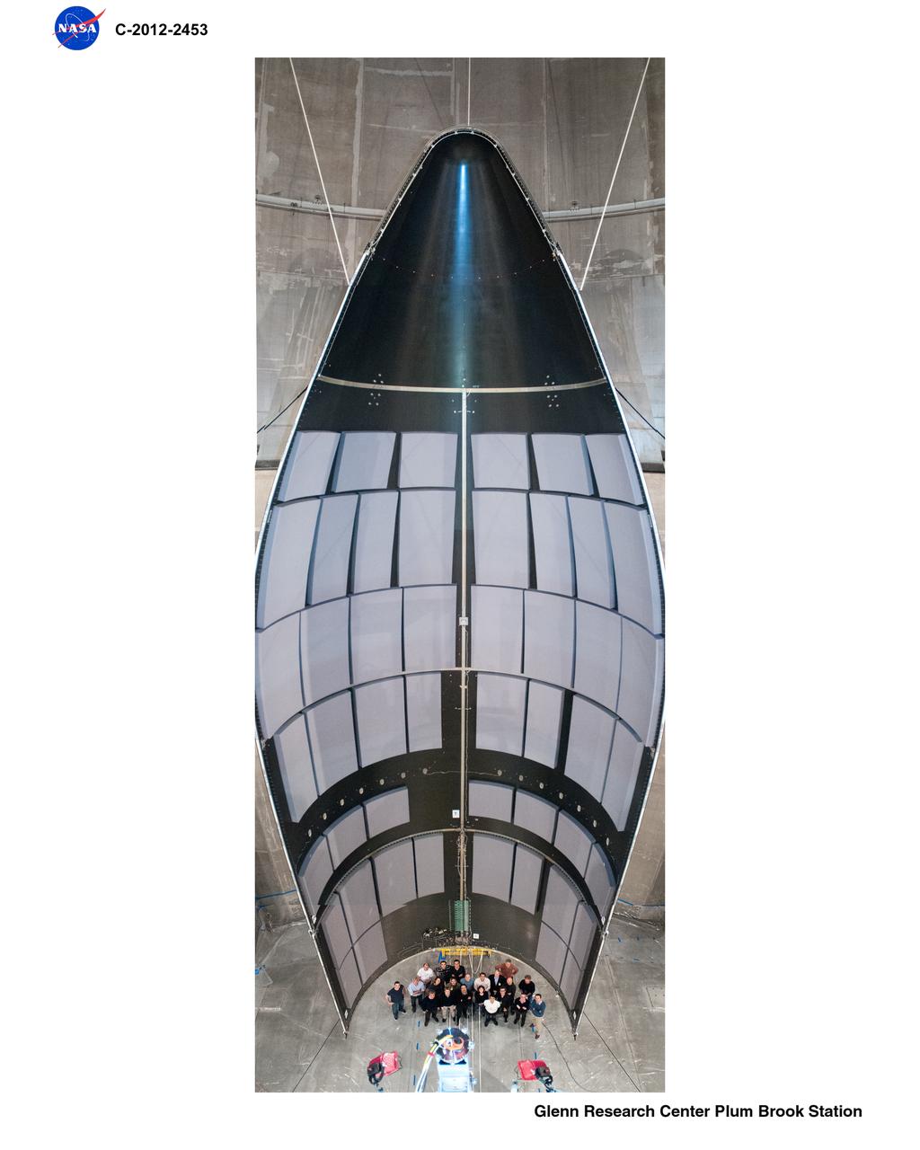
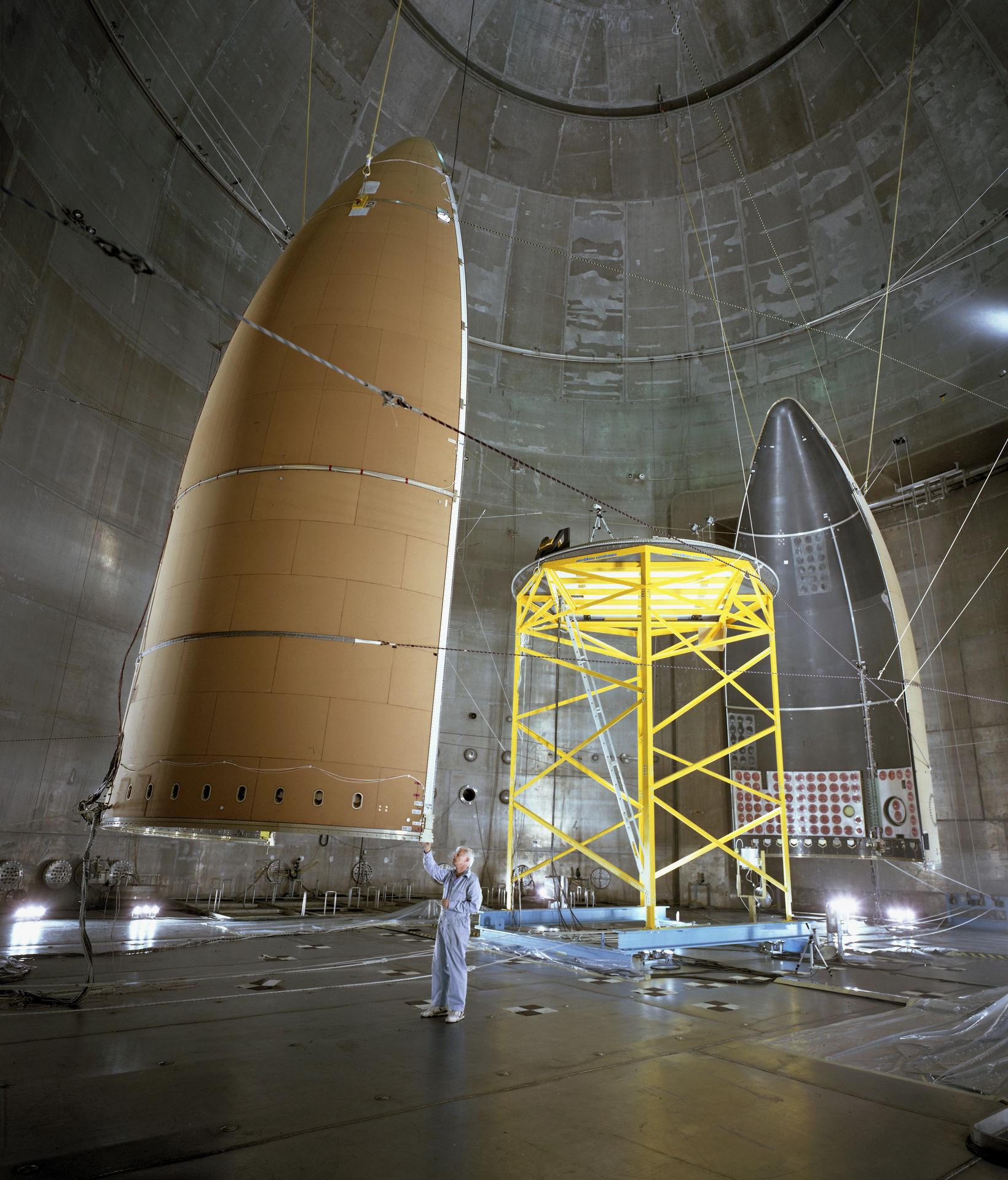
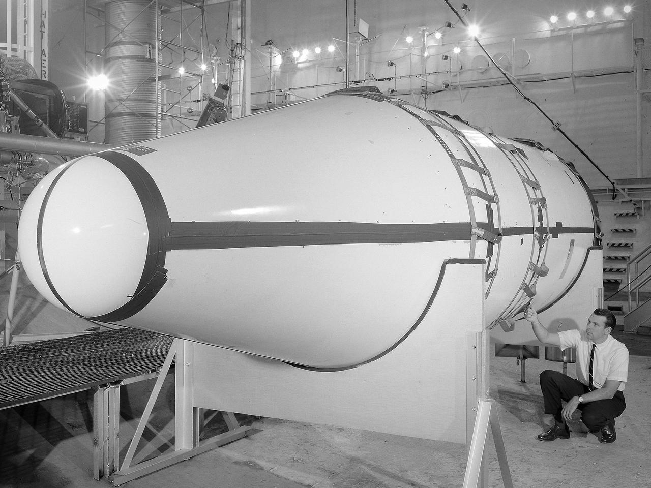
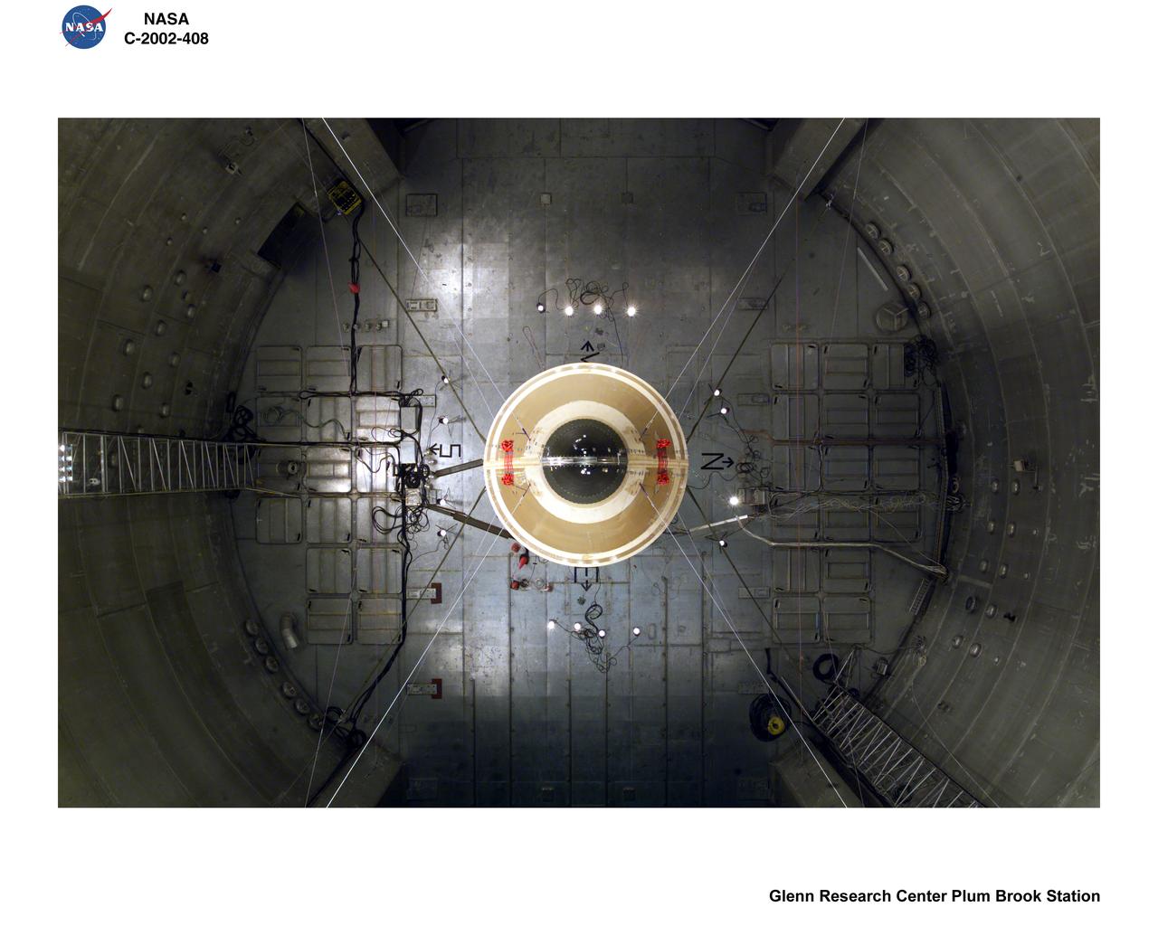
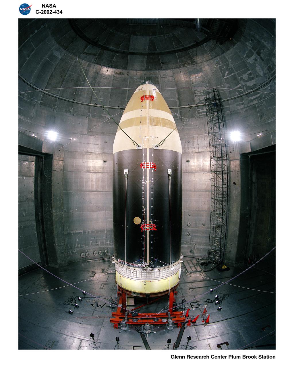
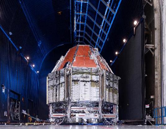
The 56-foot tall, 24,400-pound Skylab shroud installed in the Space Power Facility’s vacuum chamber at the National Aeronautics and Space Administration’s (NASA) Plum Brook Station. The Space Power Facility, which began operations in 1969, is the largest high vacuum chamber ever built. The chamber is 100 feet in diameter and 120 feet high. It can produce a vacuum deep enough to simulate the conditions at 300 miles altitude. The Space Power Facility was originally designed to test nuclear-power sources for spacecraft during long durations in a space atmosphere, but it was never used for that purpose. Payload shrouds are aerodynamic fairings to protect the payload during launch and ascent to orbit. The Skylab mission utilized the largest shroud ever attempted. Unlike previous launches, the shroud would not be jettisoned until the spacecraft reached orbit. NASA engineers designed these tests to verify the dynamics of the jettison motion in a simulated space environment. Fifty-four runs and three full-scale jettison tests were conducted from mid-September 1970 to June 1971. The shroud behaved as its designers intended, the detonators all fired, and early design issues were remedied by the final test. The Space Power Facility continues to operate today. The facility can sustain a high vacuum; simulate solar radiation via a 4-megawatt quartz heat lamp array, solar spectrum by a 400-kilowatt arc lamp, and cold environments. Test programs at the facility include high-energy experiments, shroud separation tests, Mars Lander system tests, deployable Solar Sail tests and International Space Station hardware tests.

Release Date: May 3, 2004 A Dying Star Shrouded by a Blanket of Hailstones Forms the Bug Nebula (NGC 6302) The Bug Nebula, NGC 6302, is one of the brightest and most extreme planetary nebulae known. The fiery, dying star at its center is shrouded by a blanket of icy hailstones. This NASA Hubble Wide Field Plantery Camera 2 image shows impressive walls of compressed gas, laced with trailing strands and bubbling outflows. Object Names: NGC 6302, Bug Nebula Image Type: Astronomical Credit: NASA, ESA and A.Zijlstra (UMIST, Manchester, UK) To learn more about this image go to: <a href="http://hubblesite.org/gallery/album/nebula/pr2004046a/" rel="nofollow">hubblesite.org/gallery/album/nebula/pr2004046a/</a> <b><a href="http://www.nasa.gov/audience/formedia/features/MP_Photo_Guidelines.html" rel="nofollow">NASA image use policy.</a></b> <b><a href="http://www.nasa.gov/centers/goddard/home/index.html" rel="nofollow">NASA Goddard Space Flight Center</a></b> enables NASA’s mission through four scientific endeavors: Earth Science, Heliophysics, Solar System Exploration, and Astrophysics. Goddard plays a leading role in NASA’s accomplishments by contributing compelling scientific knowledge to advance the Agency’s mission. <b>Follow us on <a href="http://twitter.com/NASAGoddardPix" rel="nofollow">Twitter</a></b> <b>Like us on <a href="http://www.facebook.com/pages/Greenbelt-MD/NASA-Goddard/395013845897?ref=tsd" rel="nofollow">Facebook</a></b> <b>Find us on <a href="http://instagram.com/nasagoddard?vm=grid" rel="nofollow">Instagram</a></b>

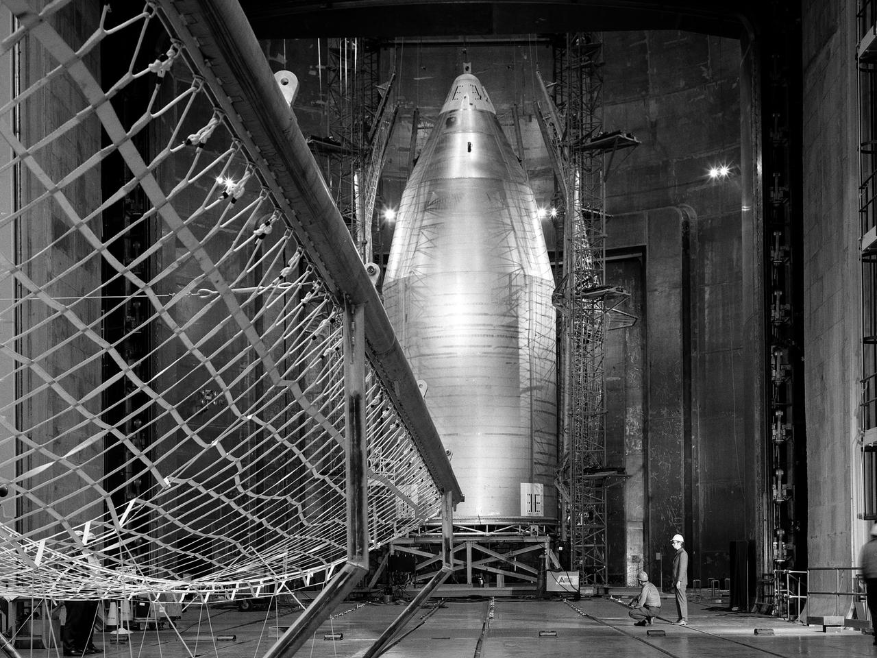
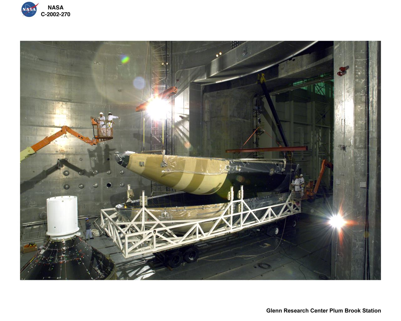
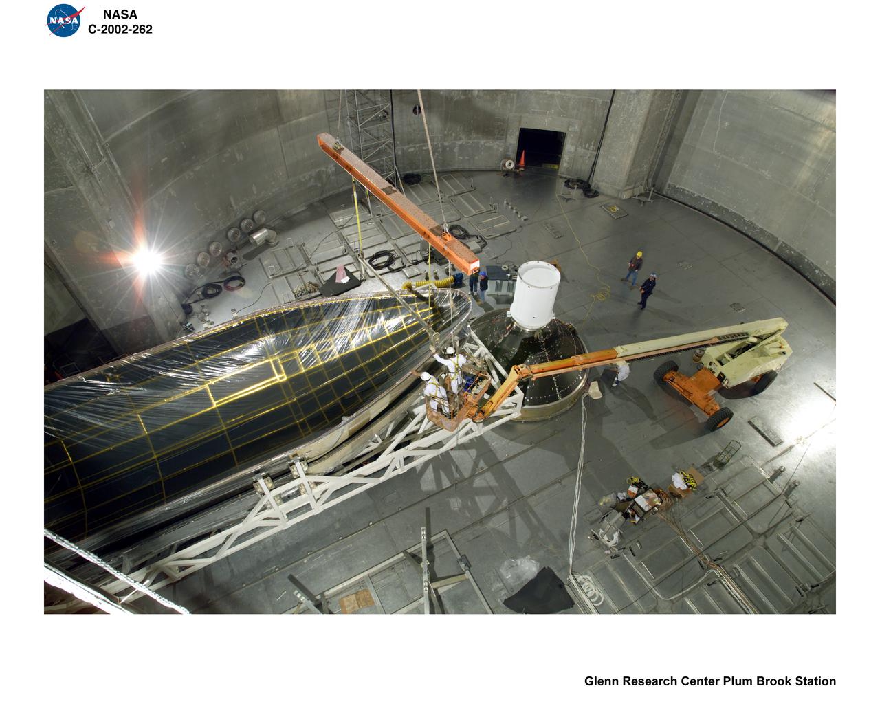
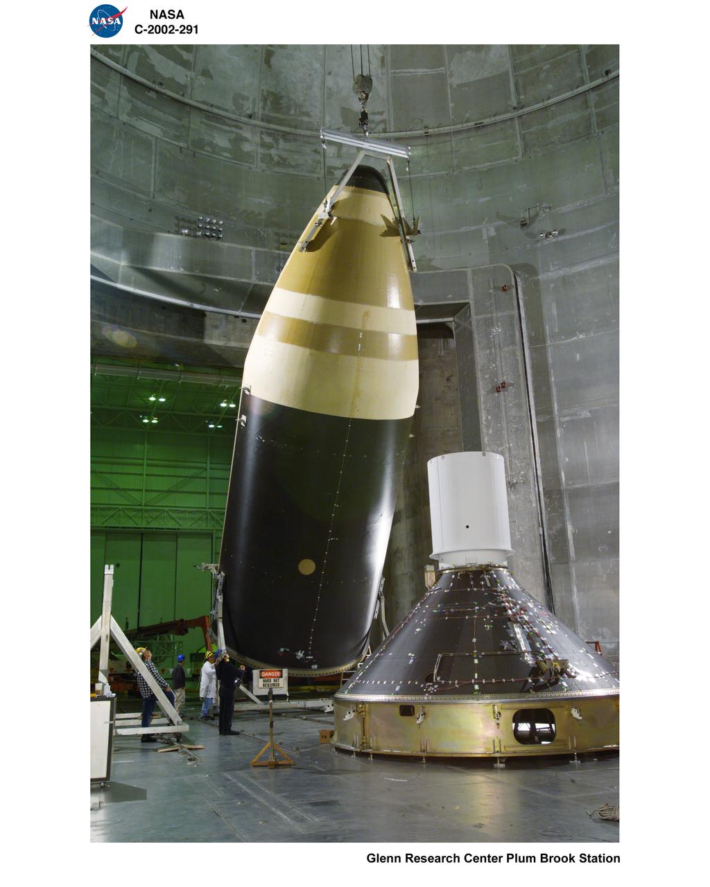
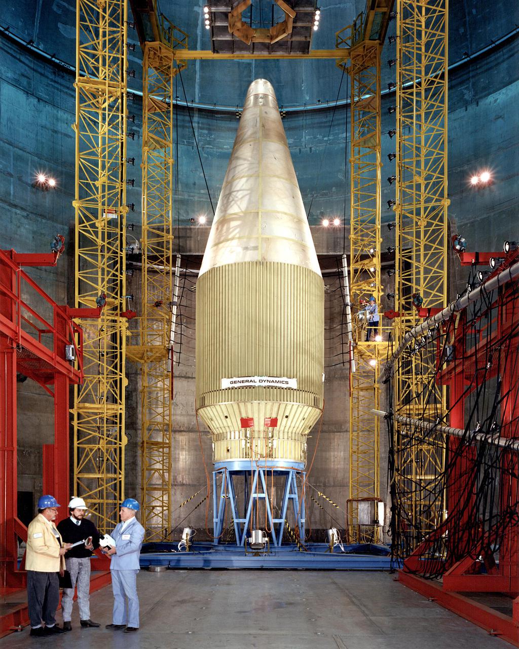
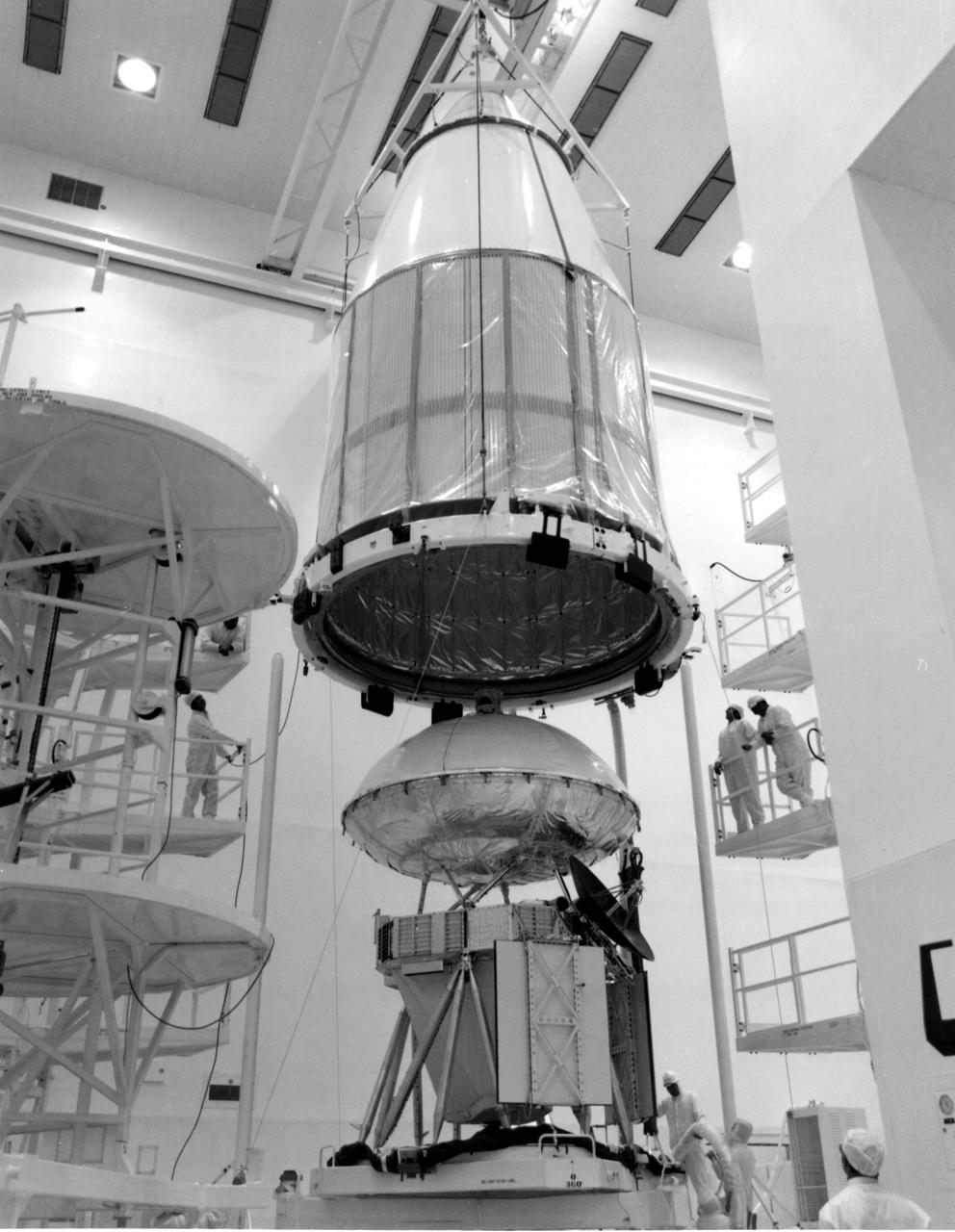
The Centaur Standard Shroud prepared for a jettison test in the Space Power Facility at the National Aeronautics and Space Administration’s (NASA) Plum Brook Station. In the late 1960s NASA engineers were planning the ambitious new Viking mission to send two rover vehicles to the surface of Mars. The Viking rovers were the heaviest payloads ever attempted by the Centaur second-stage rocket. Each Viking was over three times the weight of the Atlas-Centaur’s previous heaviest payload. Consequently, NASA engineers sought to mate the Centaur with the more powerful Titan III booster for the launches. General Dynamics created a new version of the Centaur, D-1T, specifically for Titan. The D-1T’s most significant modification was a completely new shroud designed by Lockheed, called the Centaur Standard Shroud. The conical two-piece covering encapsulated the payload to protect it against adverse conditions and improve the aerodynamics as the launch vehicle passed through the atmosphere. The shroud would be jettisoned when the vehicle reached the edge of space. A string of tests were conducted in Plum Brook’s Nuclear Rocket Dynamics and Control Facility (B-3) during 1973 and 1974. The new shroud performed flawlessly during the actual Viking launches in 1975. Viking 1 and 2 operated on the Martian surface until November 1982 and April 1980, respectively.
ARIANE 5 SHROUD TEST
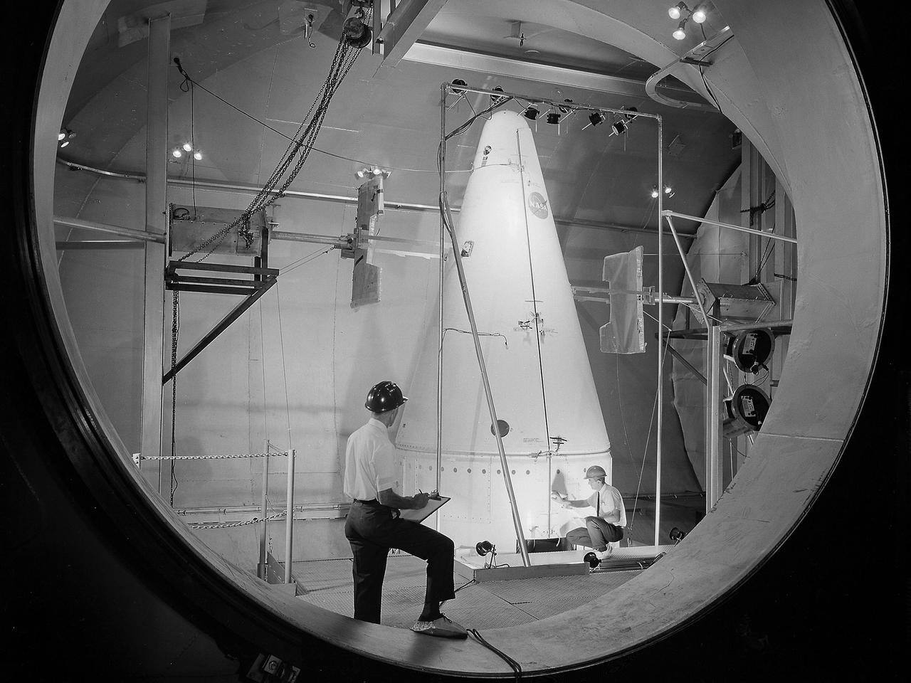
Researchers at the National Aeronautics and Space Administration (NASA) Lewis Research Center conducted a series of shroud jettison tests for the second Orbiting Astronomical Observatory (OAO-2) in the Space Power Chambers during April 1968. The Orbiting Astronomical Observatory satellites were designed by Goddard Space Flight Center to study and retrieve ultraviolet data on stars and galaxies which earthbound and atmospheric telescopes could not view due to ozone absorption. The shroud jettison system was tested in the Space Power Chambers. In 1961, NASA Lewis management decided to convert its Altitude Wind Tunnel into two large test chambers and later renamed it the Space Power Chambers. The conversion, which took over two years, included removing the tunnel’s internal components and inserting bulkheads to seal off the new chambers. The larger chamber, seen here, could simulate altitudes of 100,000 feet. These chambers were used for a variety of tests on the Centaur second-stage rocket until the early 1970s. The first OAO mission in 1965 failed due to problems with the satellite. OAO-2 would be launched on an Atlas/Centaur with a modified Agena shroud. The new shroud was 18 feet longer than the normal Centaur payload shrouds. This new piece of hardware was successfully qualified during three tests at 90,000 feet altitude in the Space Power Chambers in April 1968. For the first time, x-rays were used to verify the payload clearance once the shroud was sealed. OAO-2 was launched on December 7, 1968 and proved to be an extremely successful mission.
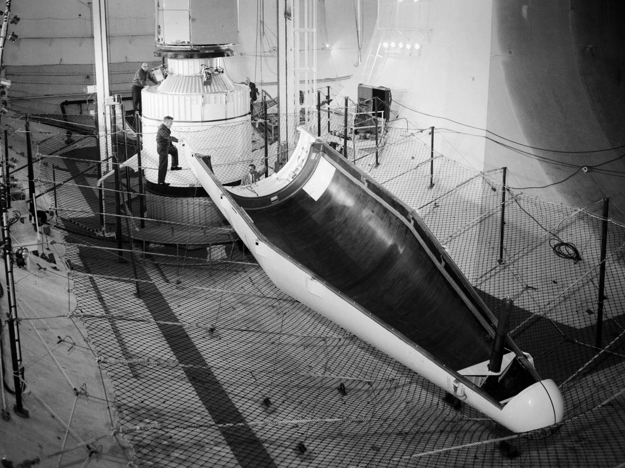
Researchers prepare a Centaur-Surveyor nose cone shroud for a separation test in the Space Power Chambers at the National Aeronautics and Space Administration (NASA) Lewis Research Center. Lewis was in the midst of an extensive effort to prepare the Centaur second-stage rocket for its missions to send the Surveyor spacecraft to the moon as a precursor to the Apollo missions. The nose fairing provided an aerodynamic shield for the payload, guidance system, and electronics package as the rocket traveled through the Earth’s atmosphere. Upon entering space, the thruster near the tip of the fairing forced the two pieces away from the space vehicle. The June 30, 1964 launch of Atlas-Centaur-3 was successful. Within a month of the launch, a Centaur shroud was obtained and installed in the Space Power Chambers. The facility was the only space tank in the country large enough to accommodate the hardware. The two halves of the fiberglass fairing were mounted vertically to a platform. Aluminum pads were set up on either side to catch the shroud halves as they were jettisoned, and a myriad of high-speed cameras were installed to record the tests. The shroud was badly damaged during the first test. It was replaced, and the test equipment redesigned. Over the course of 11 runs during the summer of 1964, the redesigned bulkhead was retested and the new fairing was validated by the final jettison on November 24, 1964. Just over two weeks later, Atlas-Centaur-4 successfully launched a mock-up Surveyor spacecraft into orbit. It was the first Centaur mission to have an error-free shroud jettison.
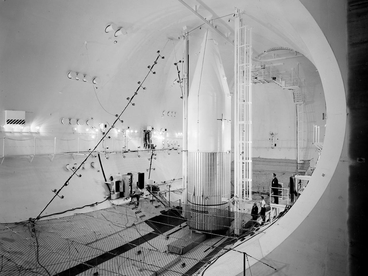
Preparations for a shroud jettison test for the Orbiting Astronomical Observatory-1 (OAO-1) satellite in the Space Power Chambers facility at the National Aeronautics and Space Administration (NASA) Lewis Research Center. The satellite was to be launched on an Atlas-Agena rocket in the spring of 1966. The 3900-pound payload was the heaviest ever attempted by Agena. The satellite was the first of three equipped with powerful telescopes to study ultraviolet data from specific stars and galaxies. In-depth observations were not possible from Earth-bound telescopes because of the filtering and distortion of the atmosphere. The OAO-1 satellite was wider in diameter than the Agena stage, so a new clamshell shroud was created to enclose both the satellite and the Agena. The clamshell shroud consisted of three sections that enclosed both the Agena and OAO-1: a fiberglass nose fairing and aluminum mid and aft fairings. The upper two fairings separated when the Atlas engines stopped, and the aft fairing fell away with the Atlas upon separation from the upper stages The large altitude tank in the Space Power Chambers could simulate altitudes up to 100,000 feet. Three shroud jettison tests were run in July 1965 and the first week of August at a simulated altitude of 20 miles. The April 8, 1966 launch from Cape Canaveral went smoothly, but the OAO-1 satellite failed after only 90 minutes due to a battery failure.
Setup of a Surveyor/Atlas/Centaur shroud in the Space Power Chambers for a leak test at the National Aeronautics and Space Administration (NASA) Lewis Research Center. Centaur was a 15,000-pound thrust second-stage rocket designed for the military in 1957 and 1958 by General Dynamics. It was the first major rocket to use the liquid hydrogen technology developed by Lewis in the 1950s. The Centaur Program suffered numerous problems before being transferred to Lewis in 1962. Several test facilities at Lewis’ main campus and Plum Brook Station were built or modified specifically for Centaur, including the Space Power Chambers. In 1961, NASA Lewis management decided to convert its Altitude Wind Tunnel into two large test chambers and later renamed it the Space Power Chambers. The conversion, which took over 2 years, included the removal of the tunnel’s internal components and insertion of bulkheads to seal off the new chambers. The larger chamber, seen here, could simulate altitudes of 100,000 feet. It was used for Centaur shroud separation and propellant management studies until the early 1970s. The leak test in this photograph was likely an attempt to verify that the shroud’s honeycomb shell did not seep any of its internal air when the chamber was evacuated to pressures similar to those found in the upper atmosphere.
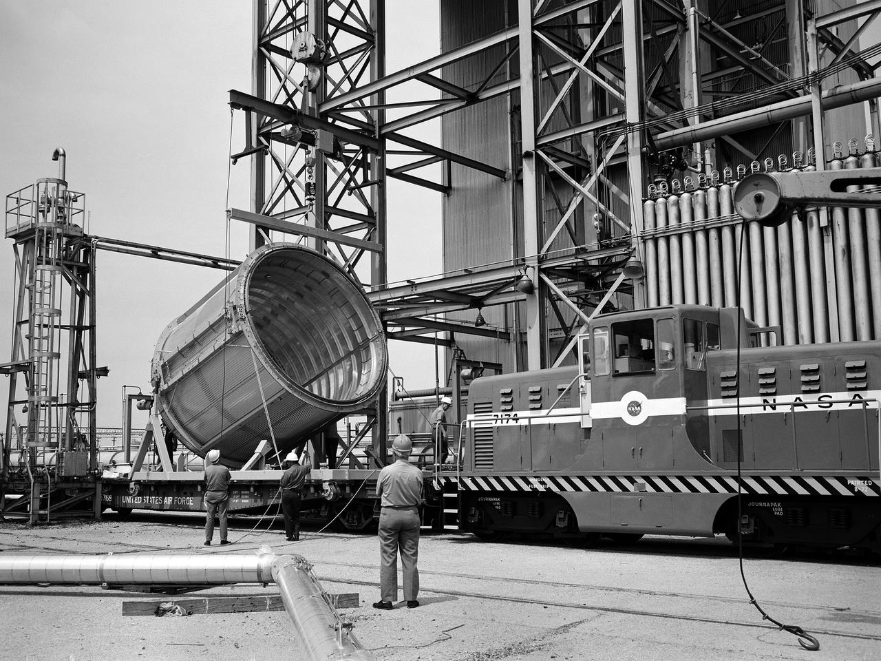
A section of the Centaur Standard Shroud transported to Nuclear Rocket Dynamics and Control Facility, or B-3 Test Stand, at the National Aeronautics and Space Administration’s (NASA) Plum Brook Station. B-3 was built in the early 1960s to test full-scale liquid hydrogen fuel systems in simulated altitude conditions. The facility was used in 1972, however, for testing of the Centaur Standard Shroud’s ejection system. In the late 1960s NASA engineers were planning the ambitious new Viking mission to send two rover vehicles to the surface of Mars. The Viking rovers were the heaviest payloads ever attempted and were over three times the weight of Atlas-Centaur’s previous heaviest payload. Consequently, NASA engineers selected the more powerful the Titan III rocket booster to mate with the Centaur. Concurrently, General Dynamics was in the process of introducing a new Centaur model for Titan—the D-1T. The biggest change for the D-1T was a completely new shroud designed by Lockheed, called the Centaur Standard Shroud. The shroud, its insulation, the Centaur ground-hold purge system, and the hydrogen tank venting system were all studied in B-3. After more than two years of preparations, the tests were run between April and July 1973. The tests determined the ultimate flight loads on two axes, established the Centaur’s load sharing, the level of propellant boiloff during launch holds, and the vent system capacity. The Centaur Standard Shroud performed flawlessly during the August 20 and September 9, 1975 launches of Viking 1 and 2.
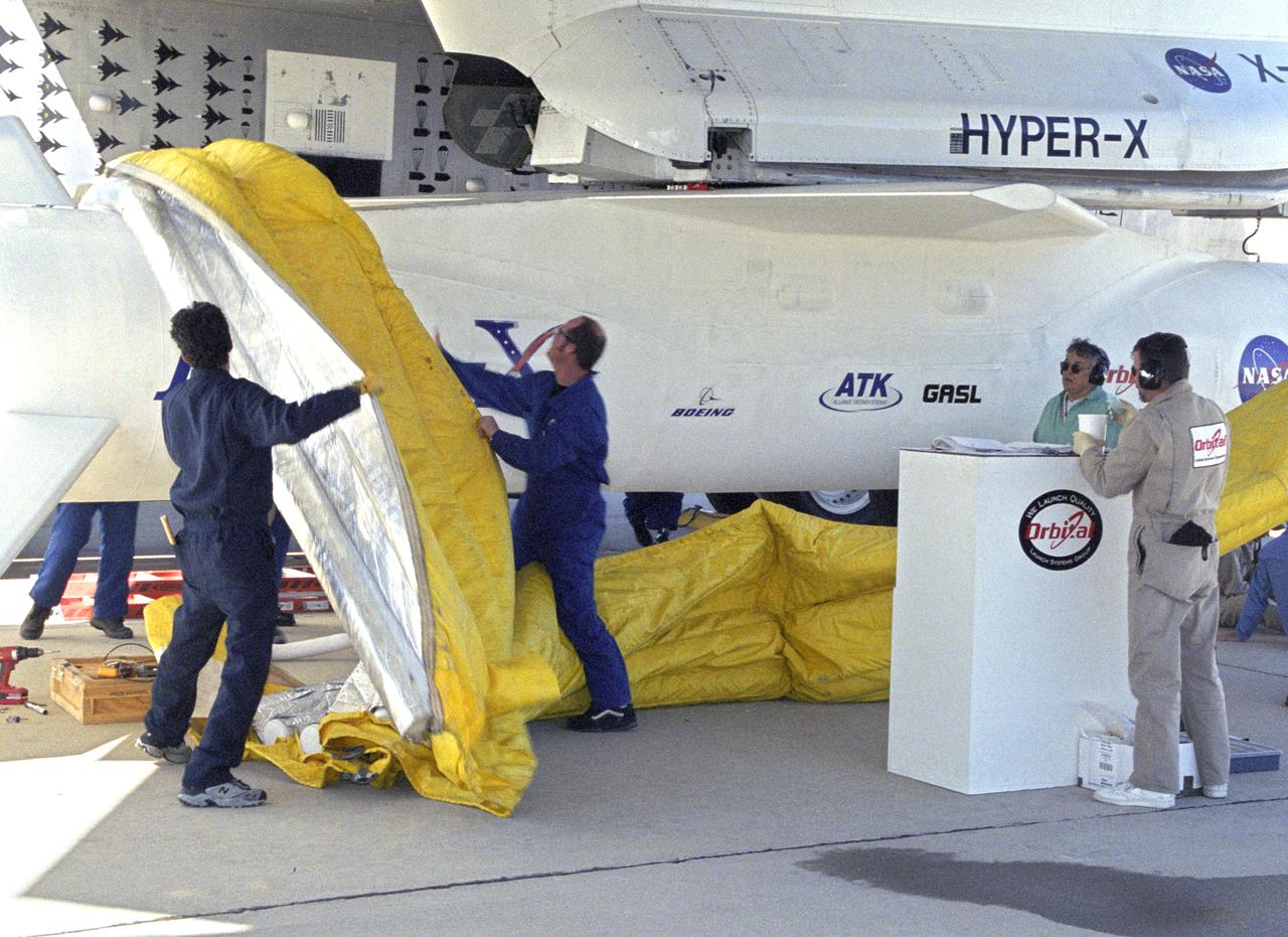
Orbital Sciences Corp. technicians remove protective shrouds from the modified Pegasus booster before takeoff on the X-43A's Mach 9.6 record scramjet flight.

This artist concept demonstrates that an invisible galaxy shrouded in dust can become glaringly bright when viewed in infrared light.
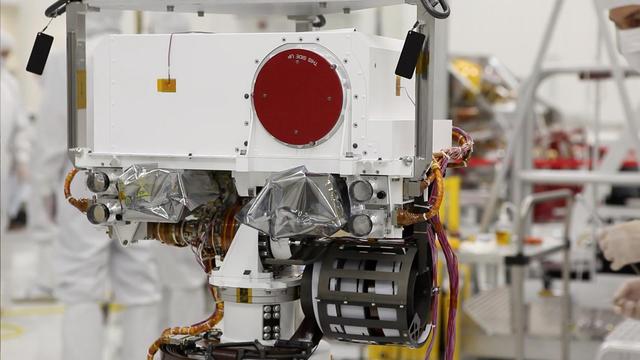
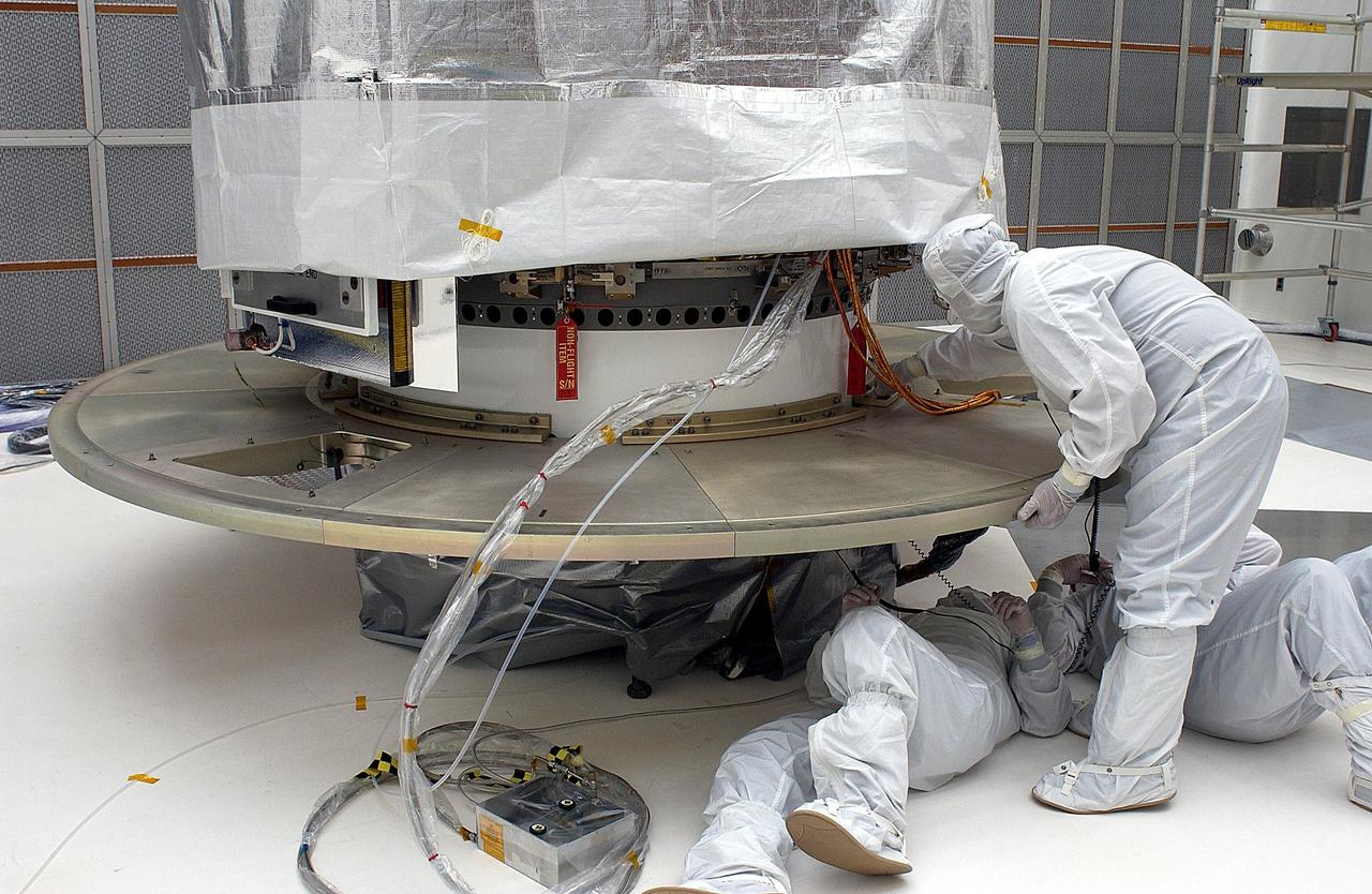
Curiosity eyes the Mastcam are shrouded in a silvery material, awaiting their first look around the clean room at NASA Jet Propulsion Laboratory, where the rover is being built.
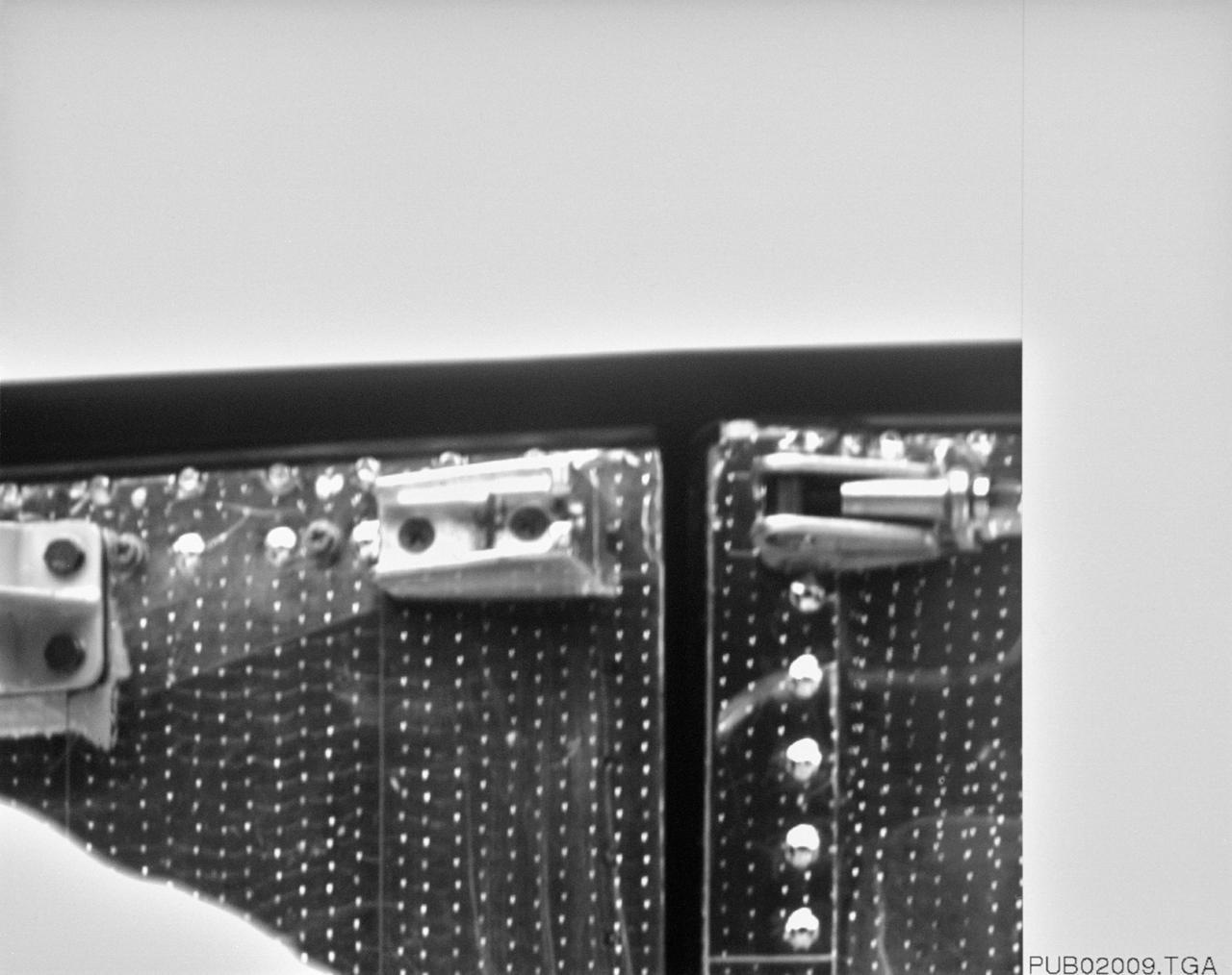
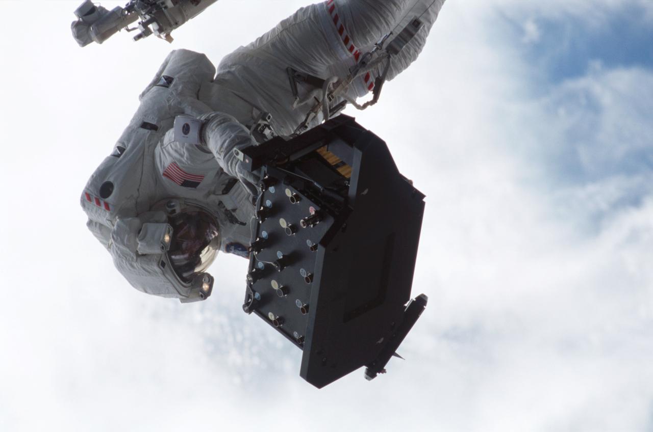
S61-E-004 (4 Dec 1993) --- This close-up view of a latch on the minus V3 aft shroud door of the Hubble Space Telescope (HST) was photographed with an Electronic Still Camera (ESC), and down linked to ground controllers soon afterward. Endeavour's crew captured the HST on December 4, 1993 in order to service the telescope. Over a period of five days, four of the seven crew members will work in alternating pairs outside Endeavour's shirt sleeve environment to service the giant telescope. Electronic still photography is a relatively new technology which provides the means for a handheld camera to electronically capture and digitize an image with resolution approaching film quality. The electronic still camera has flown as an experiment on several other shuttle missions.
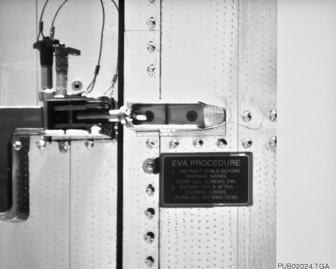
S61-E-010 (4 Dec 1993) --- This close-up view of a latch on the minus V3 aft shroud door of the Hubble Space Telescope (HST) was photographed with an Electronic Still Camera (ESC), and down linked to ground controllers soon afterward. Endeavour's crew captured the HST on December 4, 1993 in order to service the telescope over a period of five days. Four of the crew members will work in alternating pairs outside Endeavour's shirt sleeve environment to service the giant telescope. Electronic still photography is a relatively new technology which provides the means for a handheld camera to electronically capture and digitize an image with resolution approaching film quality. The electronic still camera has flown as an experiment on several other shuttle missions.
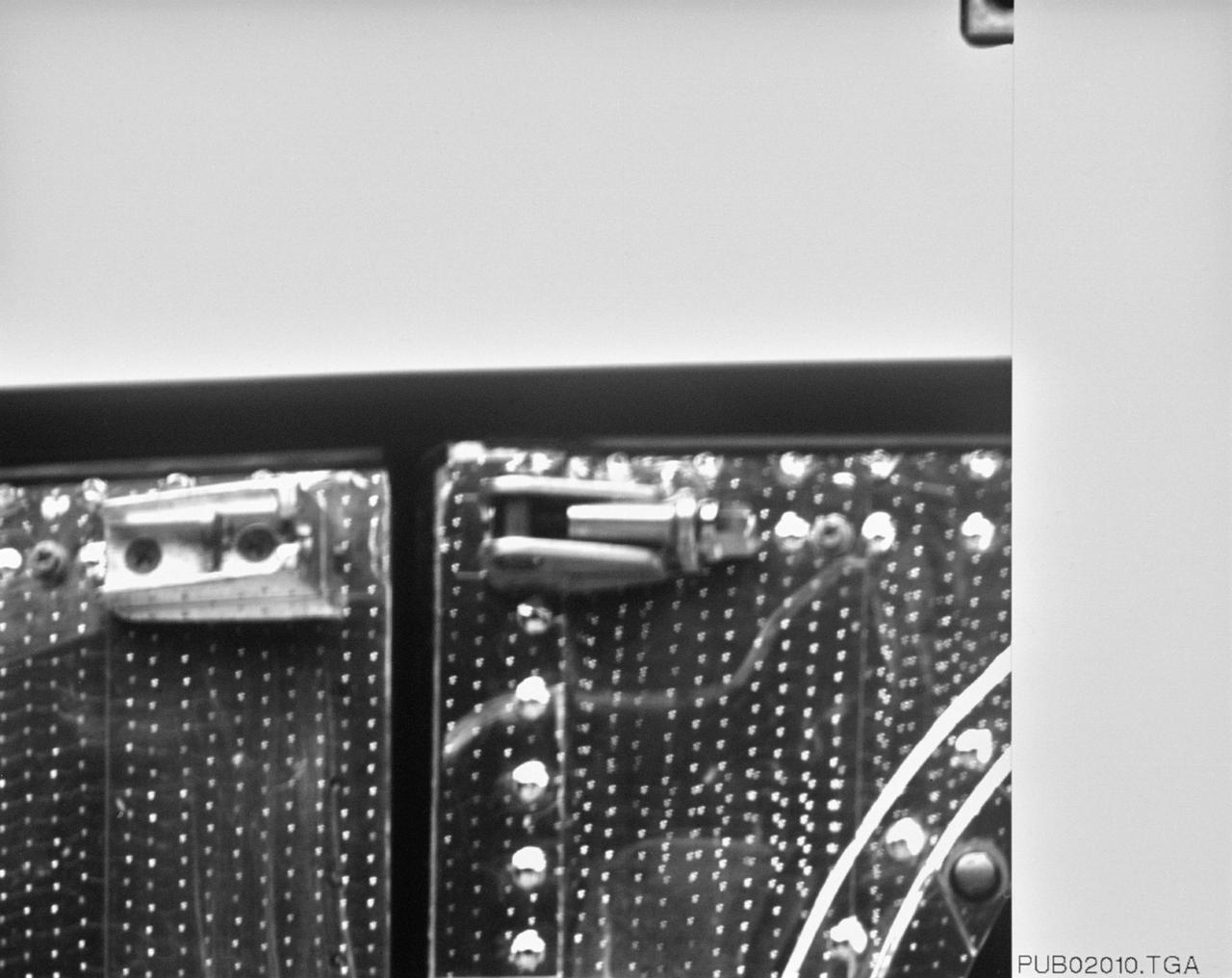
S61-E-005 (4 Dec 1993) --- This close-up view of a latch on the minus V3 aft shroud door of the Hubble Space Telescope (HST) was photographed with an Electronic Still Camera (ESC), and down linked to ground controllers soon afterward. Endeavour's crew captured the HST on December 4, 1993 in order to service the telescope. Over a period of five days, four of the seven crew members will work in alternating pairs outside Endeavour's shirt sleeve environment to service the giant telescope. Electronic still photography is a relatively new technology which provides the means for a handheld camera to electronically capture and digitize an image with resolution approaching film quality. The electronic still camera has flown as an experiment on several other shuttle missions.
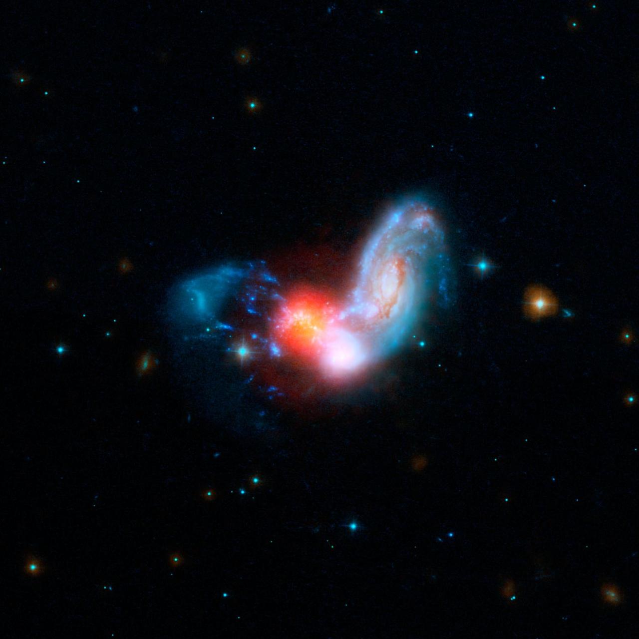
A brilliant burst of star formation is revealed in this image combining observations from NASA Spitzer and Hubble Space Telescopes. The collision of two spiral galaxies has triggered this luminous starburst.
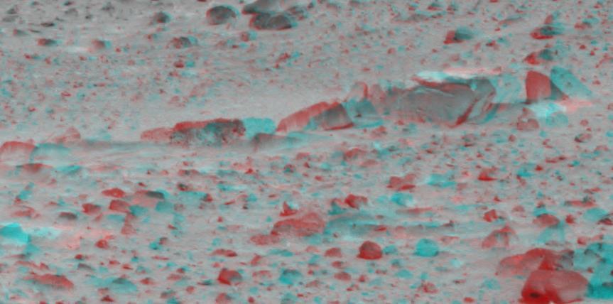
Dust-covered rocks can be seen in this portion of the 3D image taken by the panoramic camera on NASA Mars Exploration Rover Spirit. 3D glasses are necessary to view this image.

This spaceborne radar image shows the Valley Island of Maui, Hawaii. The cloud-penetrating capabilities of radar provide a rare view of many parts of the island, since the higher elevations are frequently shrouded in clouds.
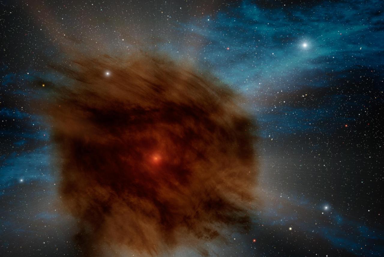
A giant star in a faraway galaxy recently ended its life with a dust-shrouded whimper instead of the more typical bang in this artist concept based on data from Spitzer Space Telescope.
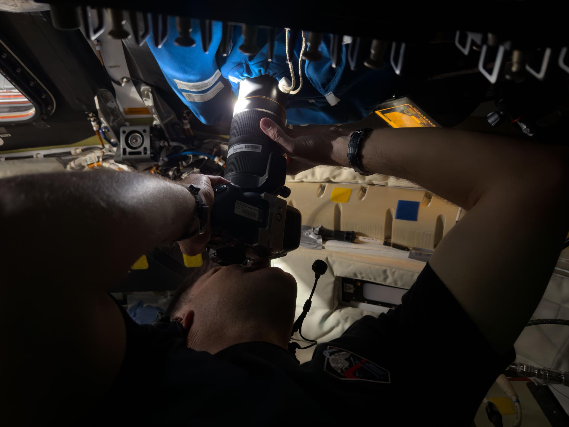
art002e009295 (April 6, 2026) – Astronaut Jeremy Hansen captures an image through the camera shroud covering window 2 of the Orion spacecraft. The camera shroud, essentially a curtain with a hole for the lens to pass through, is used to prevent light from the cabin from reflecting on the windowpanes.
BOEING DELTA 4 SHROUD SEPARATION TEST IN SPACE POWER FACILITY AT NASA PLUM BROOK STATION
BOEING DELTA 4 SHROUD SEPARATION TEST IN SPACE POWER FACILITY AT NASA PLUM BROOK STATION
BOEING DELTA 4 SHROUD SEPARATION TEST IN SPACE POWER FACILITY AT NASA PLUM BROOK STATION
BOEING DELTA 4 SHROUD SEPARATION TEST IN SPACE POWER FACILITY AT NASA PLUM BROOK STATION
BOEING DELTA 4 SHROUD SEPARATION TEST IN SPACE POWER FACILITY AT NASA PLUM BROOK STATION
Employees at the Space Power Facility (SPF) at Plum Brook Station tested a new generation of Atlas/Centaur launch vehicles. General Dynamics conducted the tests December 22 and January 3, 1990 to determine the flight readiness of a new 14-foot diameter payload fairing. The fairing will accommodate new weather satellites, the U.S. Air Force Combined Release and Radiation Effects (CRRES) satellite, and other future payloads. At a simulated altitude of 85,000 feet, the cone-shaped fairing separated in half from a hinge at the bottom. Half of the fairing was then released from the test stack and recovered in a catch-net. The payload fairing separations were the first tests of major space hardware to be conducted in the SPF in more than 15 years.
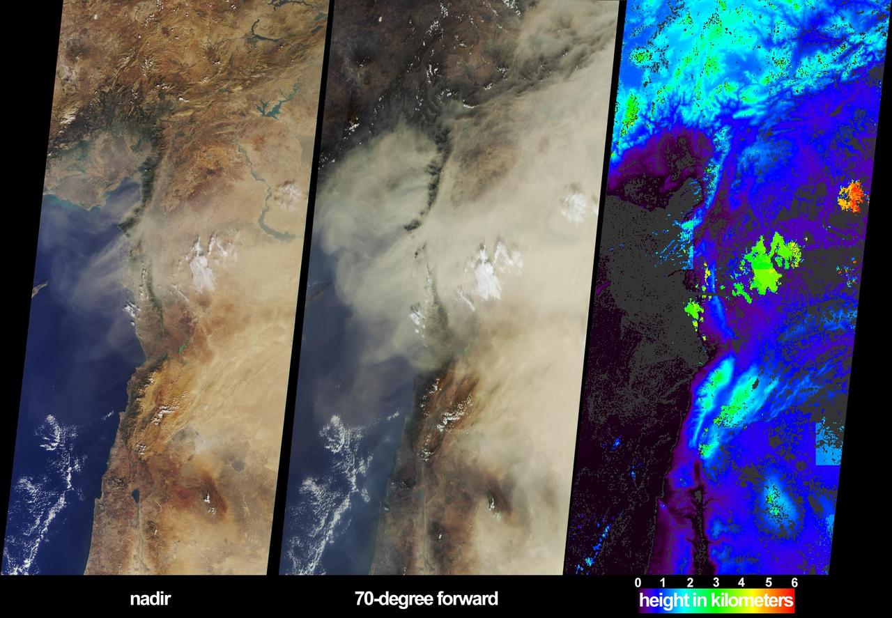
These images from NASA Terra satellite, captured on October 18, 2002, display a large dust plume extended across countries bordering the eastern Mediterranean Sea.
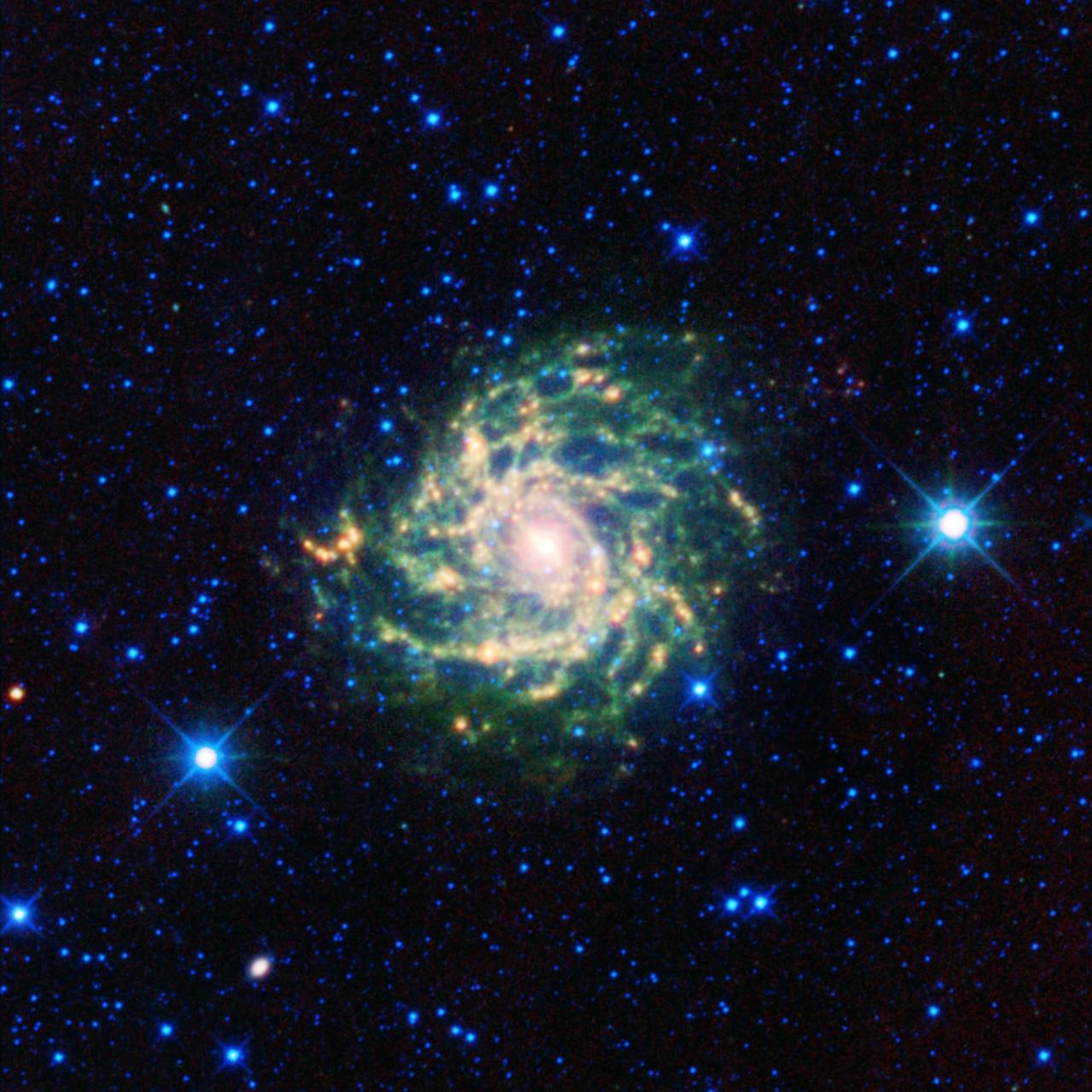
A leggy cosmic creature comes out of hiding in this new infrared view from NASA Wide-field Infrared Survey Explorer. The spiral beauty, called IC 342 and sometimes the hidden galaxy, is shrouded behind our own galaxy, the Milky Way.
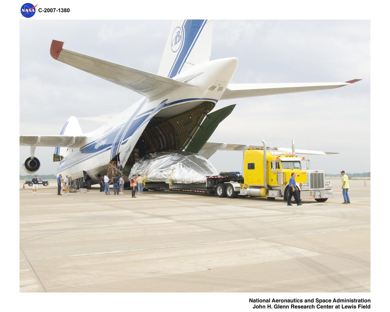
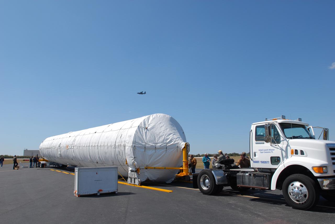
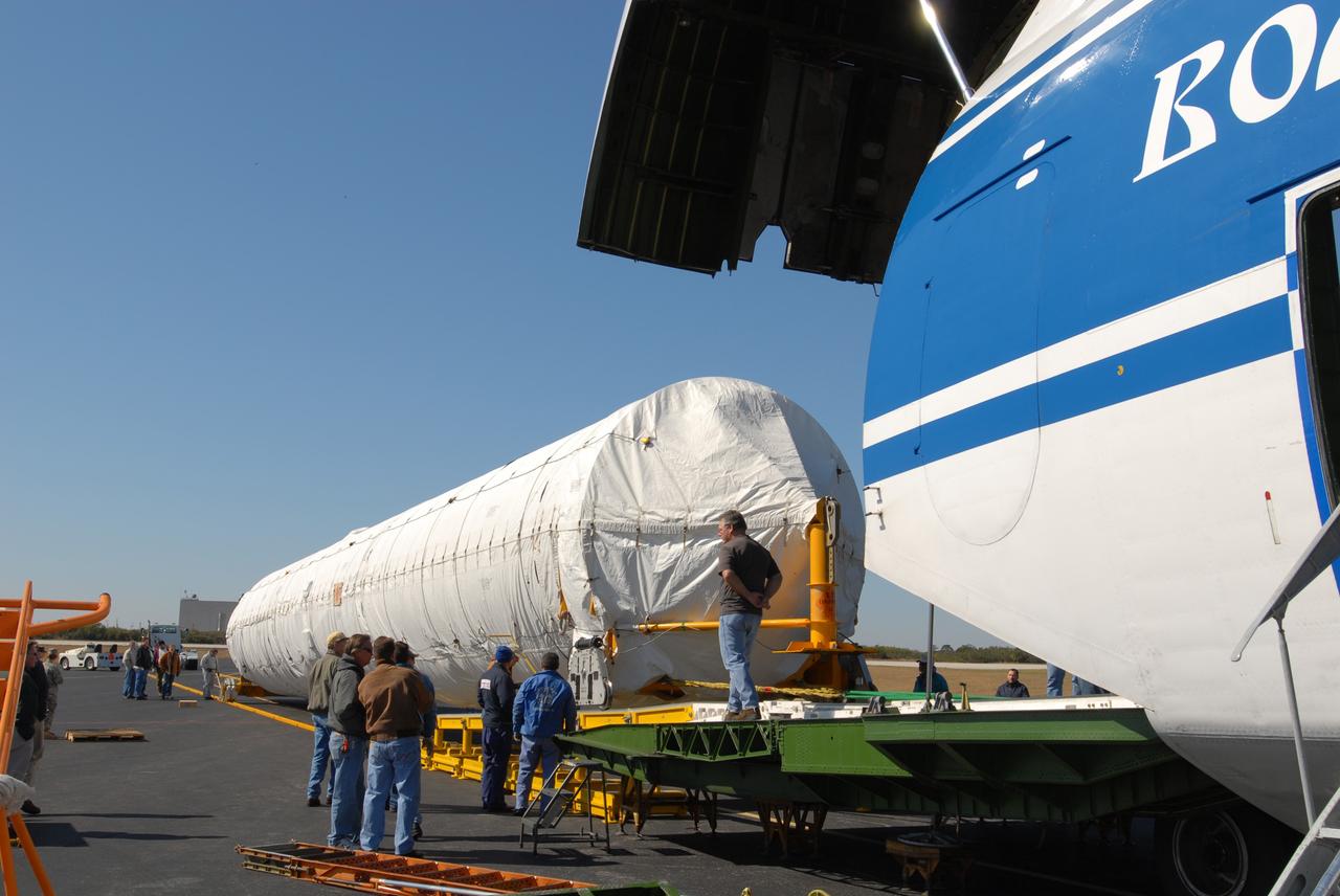
Ariane V (5) Fairing Shroud Components being moved from Cleveland Hopkins Airport to NASA Plum Brook Station, Sandusky, Ohio - 8-07
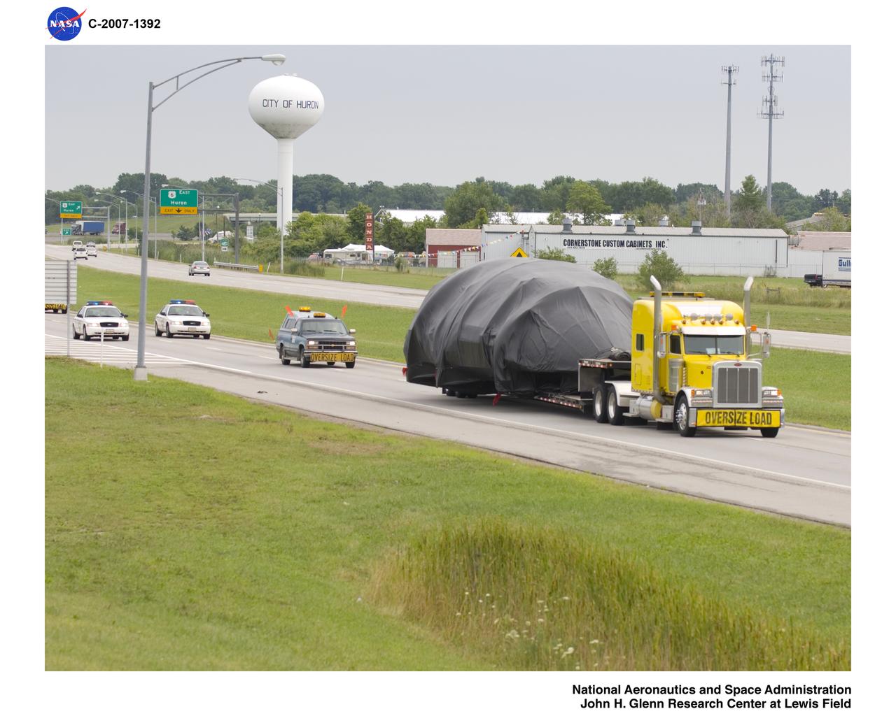
Ariane V (5) Fairing Shroud Components being moved from Cleveland Hopkins Airport to NASA Plum Brook Station, Sandusky, Ohio - 8-07
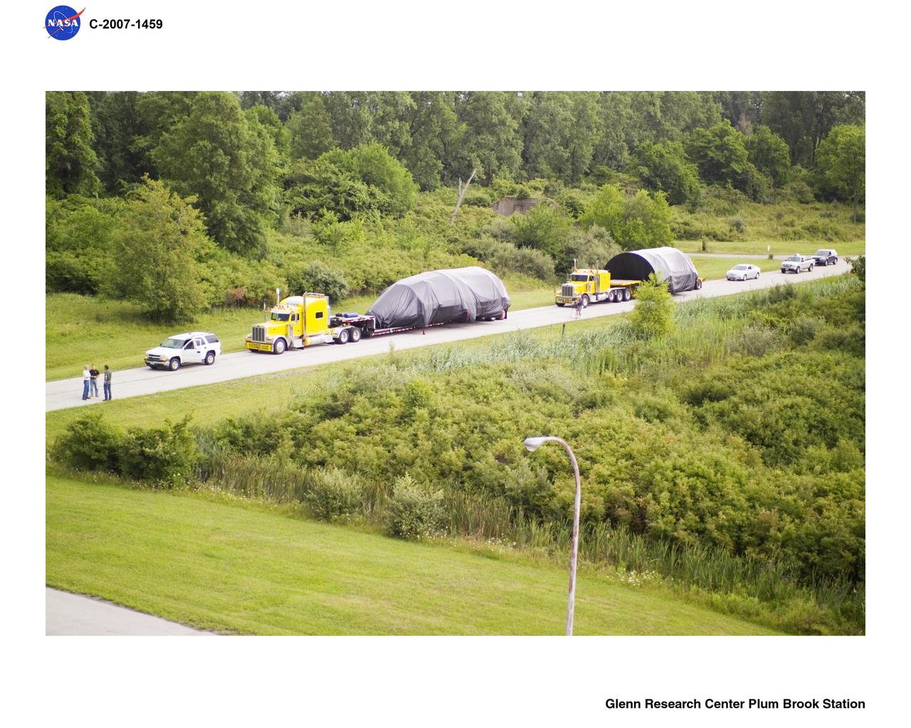
Ariane V (5) Fairing Shroud Components being moved from Cleveland Hopkins Airport to NASA Plum Brook Station, Sandusky, Ohio - 8-07
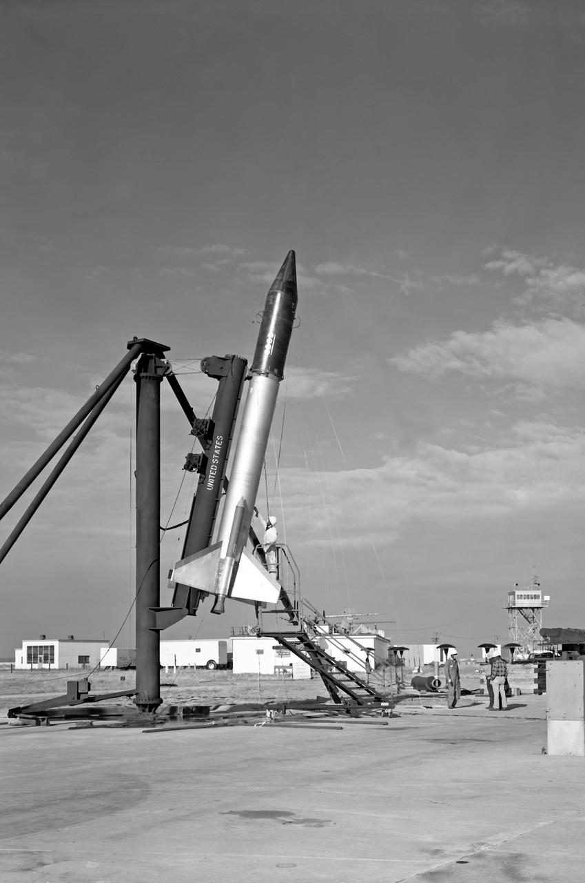
Shot put with shroud over payload - carried early Echo satellite (which burst before achieving orbit). This was the first attempt to launch the Echo satellite.
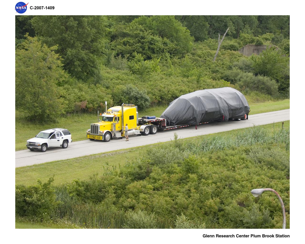
Ariane V (5) Fairing Shroud Components being moved from Cleveland Hopkins Airport to NASA Plum Brook Station, Sandusky, Ohio - 8-07
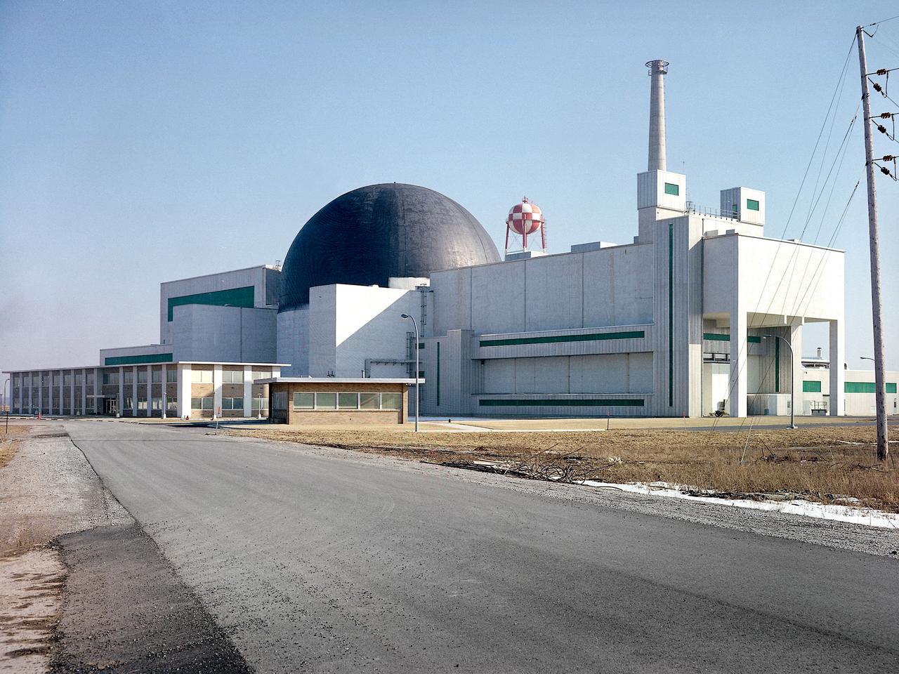
Exterior view of the Space Power Facility at the National Aeronautics and Space Administration’s (NASA) Plum Brook Station in Sandusky, Ohio. The $28.4-million facility, which began operations in 1969, is the largest high vacuum chamber ever built. The chamber is 100 feet in diameter and 120 feet high. It produces a vacuum deep enough to simulate the conditions at 300 miles altitude. The facility can sustain a high vacuum; simulate solar radiation via a 4-megawatt quartz heat lamp array, solar spectrum by a 400-kilowatt arc lamp, and cold environments. The Space Power Facility was originally designed to test nuclear power sources for spacecraft during long durations in a space atmosphere, but it was never used for that purpose. The facility’s first test in 1970 involved a 15 to 20-kilowatt Brayton Cycle Power System for space applications. Three different methods of simulating solar heat were employed during the Brayton tests. The facility was also used for jettison tests of the Centaur Standard Shroud. The shroud was designed for the new Titan-Centaur rocket that was scheduled to launch the Viking spacecraft to Mars. The new shroud was tested under conditions that simulated the time from launch to the separation of the stages. Test programs at the facility include high-energy experiments, shroud separation tests, Mars Lander system tests, deployable Solar Sail tests and International Space Station hardware tests.
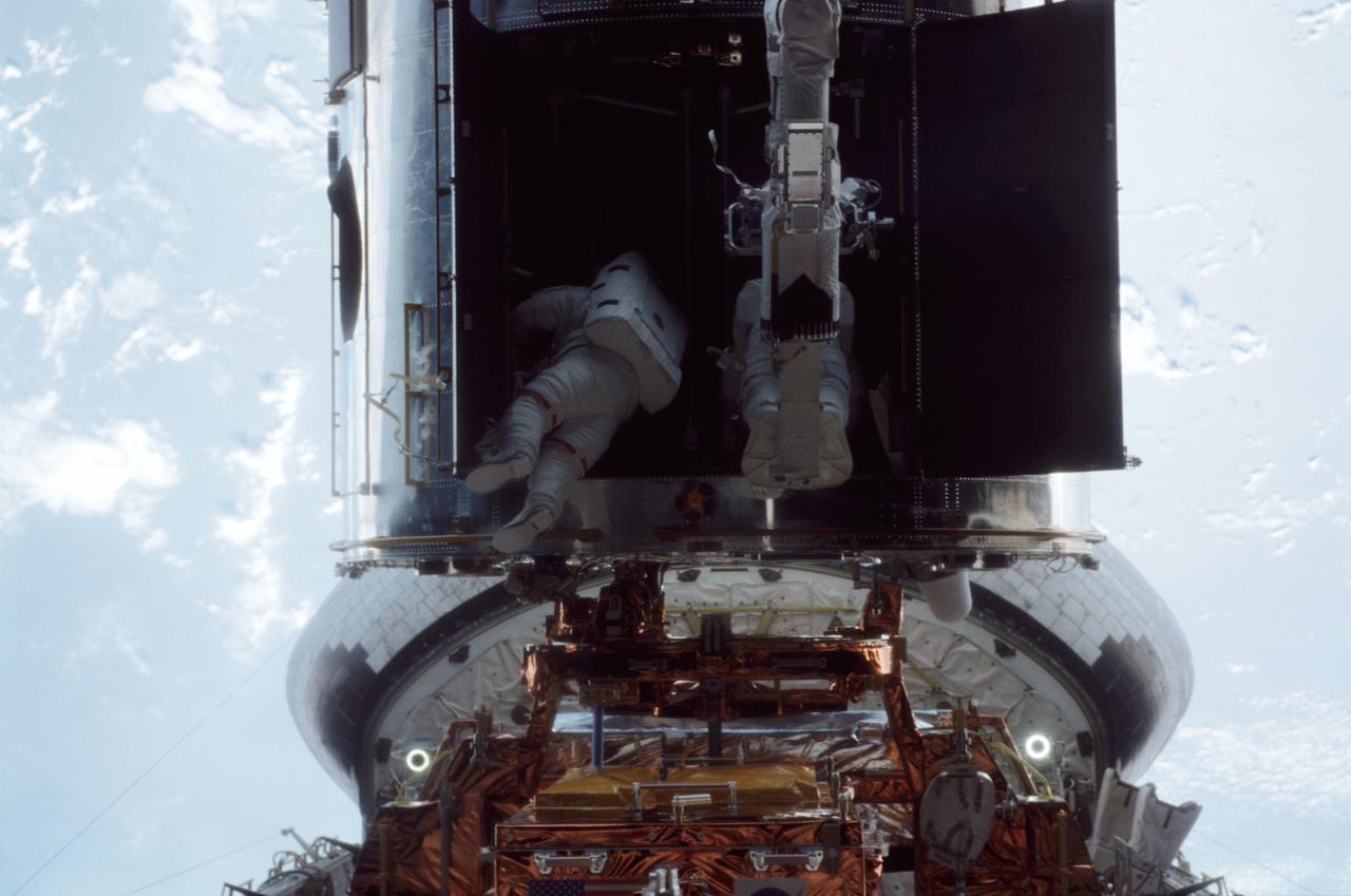
STS109-315-005 (8 March 2002) --- Barely visible within the Hubble Space Telescope's heavily shadowed shroud doors, astronauts John M. Grunsfeld (left) and Richard M. Linnehan participate in the final space walk of the STS-109 mission. The crew of the space shuttle Columbia completed the last of its five ambitious space walks early on March 8, 2002, with the successful installation of an experimental cooling system for Hubble’s Near-Infrared Camera and Multi-Object Spectrometer (NICMOS). The NICMOS has been dormant since January 1999 when its original coolant ran out. Astronauts Grunsfeld and Linnehan began their third spacewalk of the mission at 2:46 a.m. CST. Linnehan was given a ride on the shuttle’s robotic arm to the aft shroud doors by astronaut Nancy J. Currie, working from the aft flight deck of Columbia. After the shroud doors were open, Linnehan was moved back to Columbia’s payload bay to remove the NICMOS cryocooler from its carrier. Grunsfeld and Linnehan then installed the cryocooler inside the aft shroud and connected cables from its Electronics Support Module (ESM). That module was installed on March 7 during a spacewalk by astronauts James H. Newman and Michael J. Massimino.

Fiber-Reinforced-Foam (FRF) Core Composite Sandwich Panel Concept for Advanced Composites Technologies Project - Preliminary Manufacturing Demonstration Articles for Ares V Payload Shroud Barrel Acreage Structure
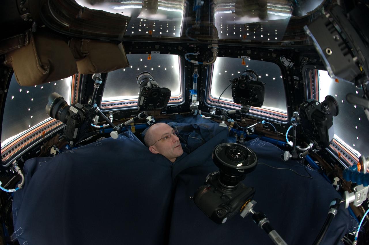
Expedition 31 flight engineer Don Pettit, with only his head visible above a shroud, is photographed in the Cupola Module. Window shutters are closed, and still cameras are positioned in front of each window

Fiber-Reinforced-Foam (FRF) Core Composite Sandwich Panel Concept for Advanced Composites Technologies Project - Preliminary Manufacturing Demonstration Articles for Ares V Payload Shroud Barrel Acreage Structure

Fiber-Reinforced-Foam (FRF) Core Composite Sandwich Panel Concept for Advanced Composites Technologies Project - Preliminary Manufacturing Demonstration Articles for Ares V Payload Shroud Barrel Acreage Structure

Planets having atmospheres rich in helium may be common in our galaxy, according to a new theory based on data from NASA's Spitzer Space Telescope. These planets would be around the mass of Neptune, or lighter, and would orbit close to their stars, basking in their searing heat. According to the new theory, radiation from the stars would boil off hydrogen in the planets' atmospheres. Both hydrogen and helium are common ingredients of gas planets like these. Hydrogen is lighter than helium and thus more likely to escape. After billions of years of losing hydrogen, the planet's atmosphere would become enriched with helium. Scientists predict the planets would appear covered in white or gray clouds. This is in contrast to our own Neptune, which is blue due to the presence of methane. Methane absorbs the color red, leaving blue. Neptune is far from our sun and hasn't lost its hydrogen. The hydrogen bonds with carbon to form methane. This artist's concept depicts a proposed helium-atmosphere planet called GJ 436b, which was found by Spitzer to lack in methane -- a first clue about its lack of hydrogen. The planet orbits every 2.6 days around its star, which is cooler than our sun and thus appears more yellow-orange in color. http://photojournal.jpl.nasa.gov/catalog/PIA19344

Researcher Bobby Sanders examines a 0.10-scale model of the Mariner-C shroud and Agena rocket in the 8- by 6-Foot Supersonic Wind Tunnel at the National Aeronautics and Space Administration (NASA) Lewis Research Center. Mariner-C and Mariner-D were identical spacecraft designed by the Jet Propulsion Laboratory to flyby Mars and photograph the Martian surface. The two Mariner spacecraft were launched by Atlas-Agena-D rockets. Lewis had taken over management of the Agena Program in October 1962. Lewis researchers investigated two different types of shrouds for the Mariner missions—an over-the-nose design and a backup pyrotechnic design. The new shroud was wider in diameter than the Agena rocket, so there was concern that this disparity might create air flow instability that could damage the shroud or destroy the vehicle. The tests in the 8- by 6 tunnel simulated launch speeds from Mach 0.56 to 1.96. Afterwards the Agena-Mariner-C model was studied in the 10- by 10-Foot Supersonic Wind Tunnel at speeds of Mach 2.0 to 3.5. Mariner-C was launched on November 4, 1964, but the payload shroud did not jettison properly and the spacecraft’s battery power did not function. The mission ended unsuccessfully two days later. Mariner-D was launched on November 28, 1964 and became the first successful mission to Mars. It was the first time a planet was photographed from space. Mariner-D’s 21 photographs revealed an inhospitable and barren landscape.

ISS046e012758 (01/18/2016) --- This long exposure image of Northern India was taken by astronauts on the International Space Station while the Earth was shrouded in darkness. Major cities in view include New Delhi, on the left side of the image, and Lahore (right), which is located to the northwest of New Delhi.
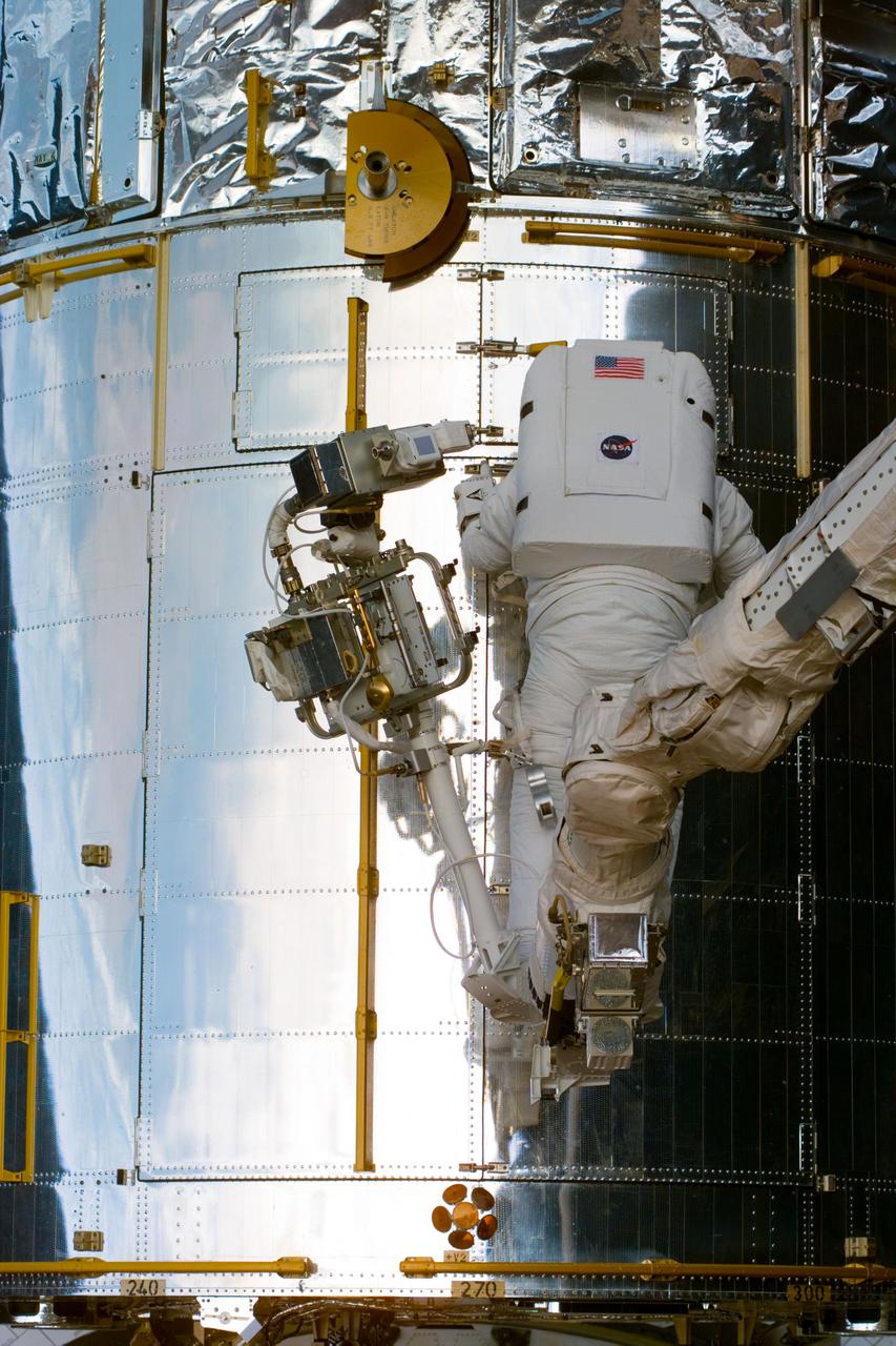
S82-E-5242 (14 Feb. 1997) --- Astronaut Steven L. Smith, STS-82 mission specialist, prepares to open aft shroud of Hubble Space Telescope (HST) for repair. This view was taken with an Electronic Still Camera (ESC).
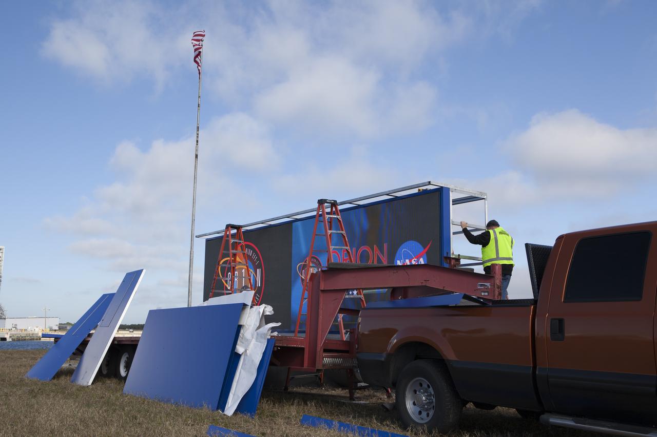
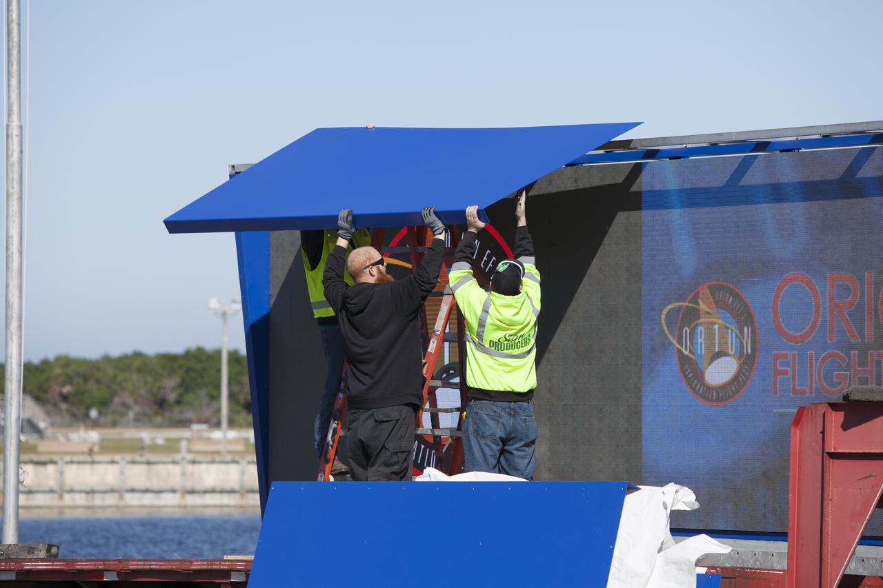
At NASA's Kennedy Space Center in Florida, a shade is placed around the new countdown clock at the spaceport's Press Site. The modern, multimedia display is similar to the screens seen at sporting venues. The new screen is nearly 26 feet wide by 7 feet high, a foot taller than the original clock. The historic countdown clock was designed by Kennedy engineers and built by space center technicians before Apollo 12 in 1969. NASA has acquired the countdown clock from the agency’s Artifact Working Group at the agency's Headquarters for display at the Kennedy Space Center Visitor Complex.

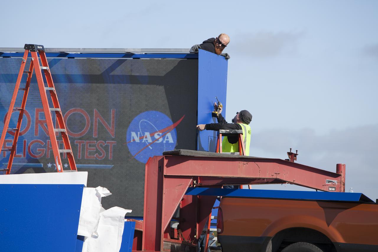
At NASA's Kennedy Space Center in Florida, a shade is placed around the new countdown clock at the spaceport's Press Site. The modern, multimedia display is similar to the screens seen at sporting venues. The new screen is nearly 26 feet wide by 7 feet high, a foot taller than the original clock. The historic countdown clock was designed by Kennedy engineers and built by space center technicians before Apollo 12 in 1969. NASA has acquired the countdown clock from the agency’s Artifact Working Group at the agency's Headquarters for display at the Kennedy Space Center Visitor Complex.
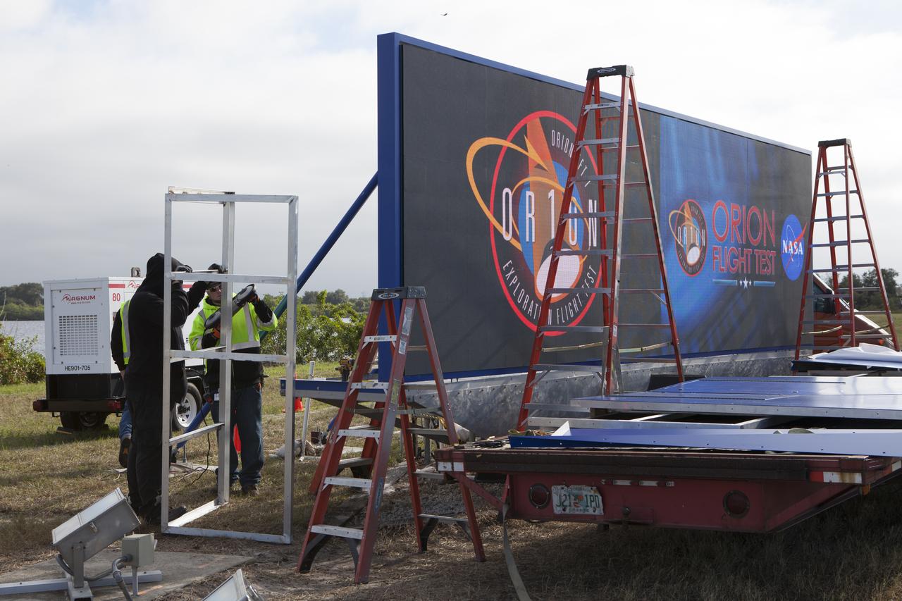
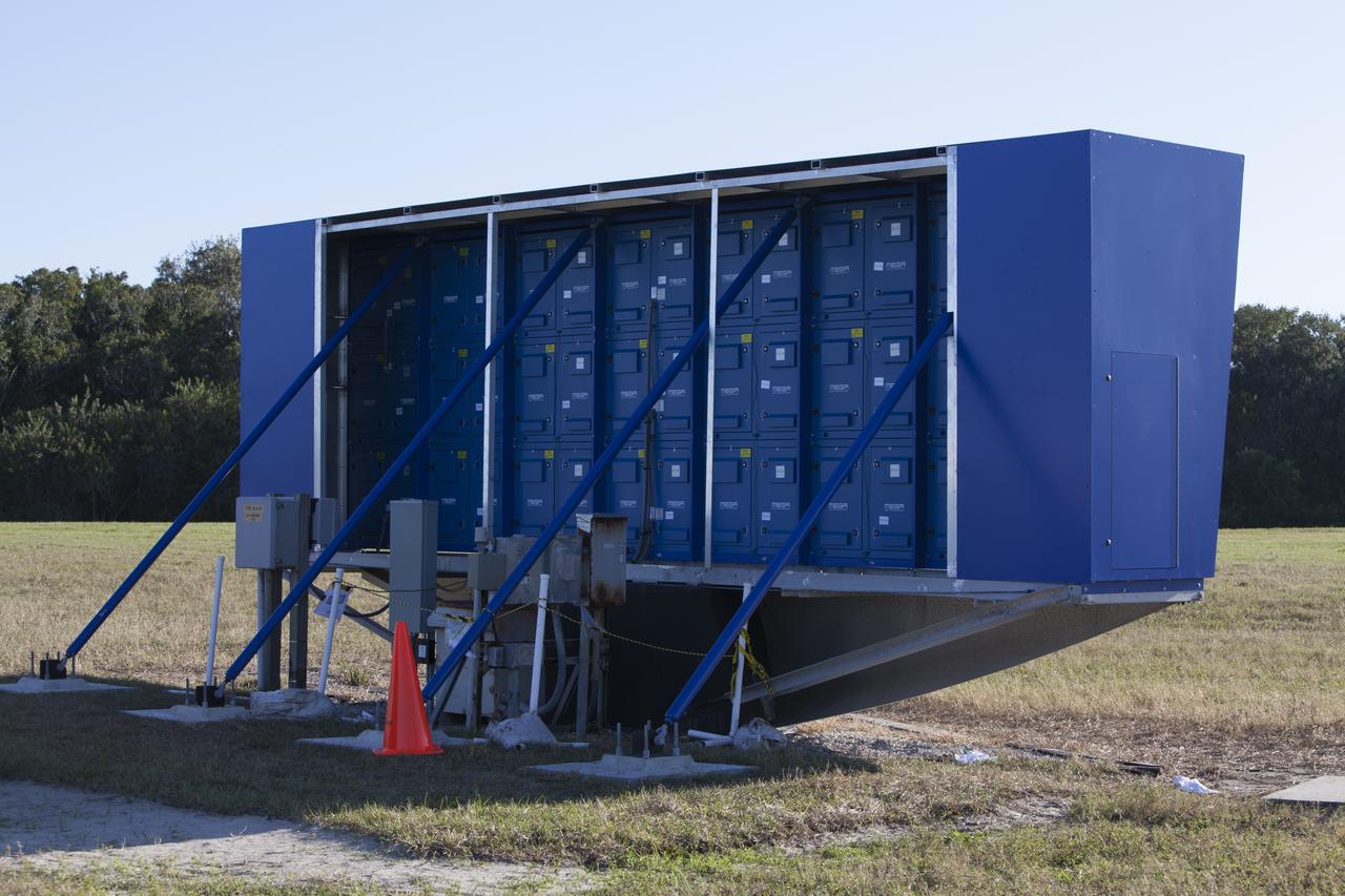
At NASA's Kennedy Space Center in Florida, a shade is placed around the new countdown clock at the spaceport's Press Site. The modern, multimedia display is similar to the screens seen at sporting venues. The new screen is nearly 26 feet wide by 7 feet high, a foot taller than the original clock. The historic countdown clock was designed by Kennedy engineers and built by space center technicians before Apollo 12 in 1969. NASA has acquired the countdown clock from the agency’s Artifact Working Group at the agency's Headquarters for display at the Kennedy Space Center Visitor Complex.
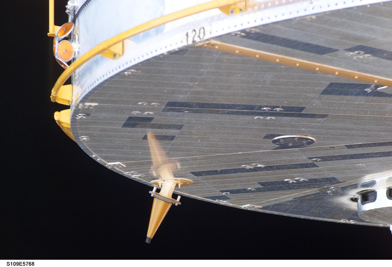
STS109-E-5768 (9 March 2002) --- The Hubble Space Telescope is released from the Space Shuttle Columbia after a week's servicing and upgrading. The STS-109 crew deployed the giant telescope at 4:04 a.m. CST (1004 GMT), March 9, 2002. Afterward, the seven crew members began to focus their attention to the trip home, scheduled for March 12. The STS-109 astronauts conducted five space walks to service and upgrade Hubble. This image was recorded with a digital still camera.
At NASA's Kennedy Space Center in Florida, a shade is placed around the new countdown clock at the spaceport's Press Site. The modern, multimedia display is similar to the screens seen at sporting venues. The new screen is nearly 26 feet wide by 7 feet high, a foot taller than the original clock. The historic countdown clock was designed by Kennedy engineers and built by space center technicians before Apollo 12 in 1969. NASA has acquired the countdown clock from the agency’s Artifact Working Group at the agency's Headquarters for display at the Kennedy Space Center Visitor Complex.
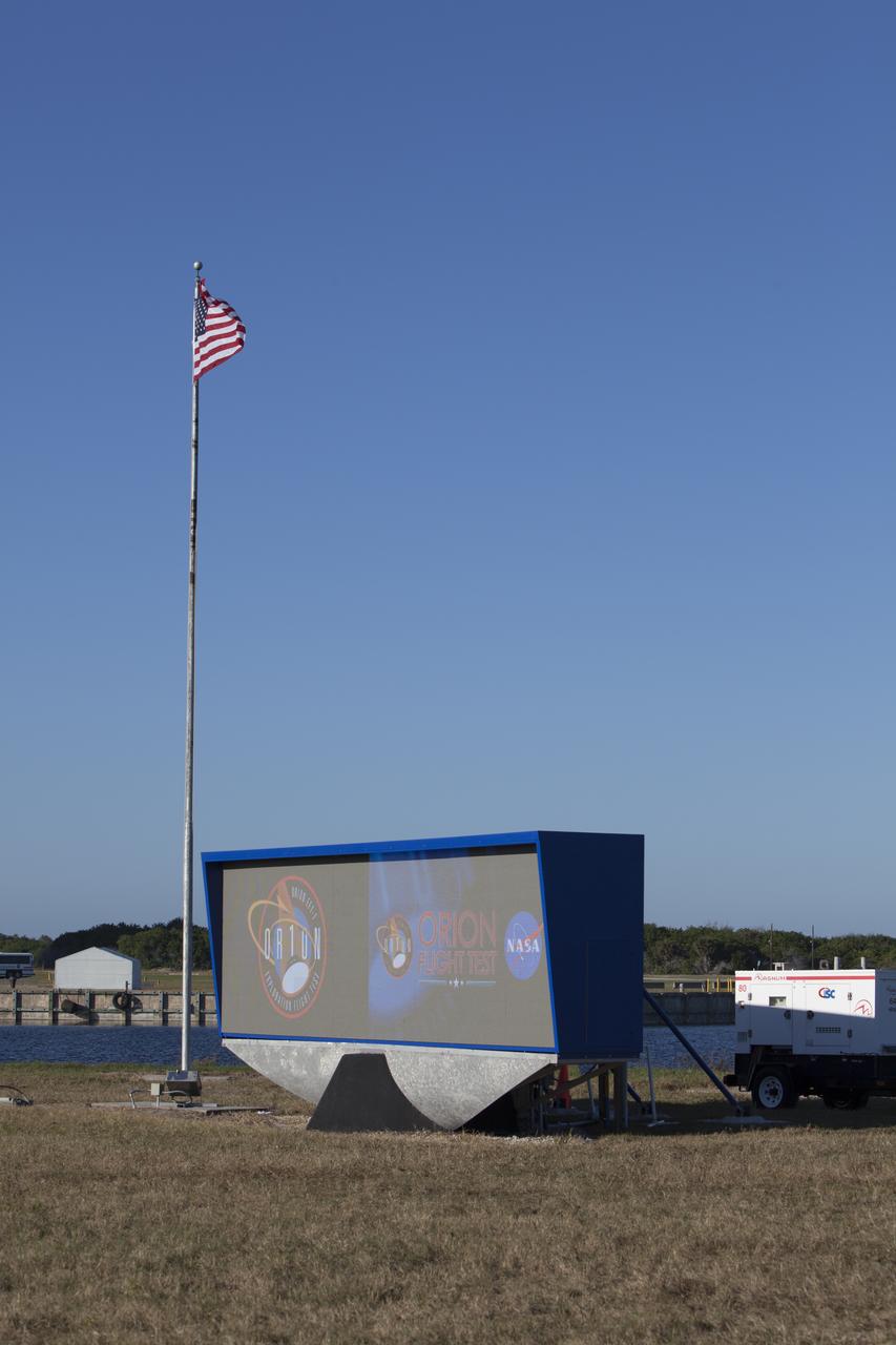
At NASA's Kennedy Space Center in Florida, a shade is placed around the new countdown clock at the spaceport's Press Site. The modern, multimedia display is similar to the screens seen at sporting venues. The new screen is nearly 26 feet wide by 7 feet high, a foot taller than the original clock. The historic countdown clock was designed by Kennedy engineers and built by space center technicians before Apollo 12 in 1969. NASA has acquired the countdown clock from the agency’s Artifact Working Group at the agency's Headquarters for display at the Kennedy Space Center Visitor Complex.
At NASA's Kennedy Space Center in Florida, a shade is placed around the new countdown clock at the spaceport's Press Site. The modern, multimedia display is similar to the screens seen at sporting venues. The new screen is nearly 26 feet wide by 7 feet high, a foot taller than the original clock. The historic countdown clock was designed by Kennedy engineers and built by space center technicians before Apollo 12 in 1969. NASA has acquired the countdown clock from the agency’s Artifact Working Group at the agency's Headquarters for display at the Kennedy Space Center Visitor Complex.
At NASA's Kennedy Space Center in Florida, a shade is placed around the new countdown clock at the spaceport's Press Site. The modern, multimedia display is similar to the screens seen at sporting venues. The new screen is nearly 26 feet wide by 7 feet high, a foot taller than the original clock. The historic countdown clock was designed by Kennedy engineers and built by space center technicians before Apollo 12 in 1969. NASA has acquired the countdown clock from the agency’s Artifact Working Group at the agency's Headquarters for display at the Kennedy Space Center Visitor Complex.

Astronomers using data from NASA's Wide-field Infrared Survey Explorer, or WISE, are helping to trace the shape of our Milky Way galaxy's spiral arms. This illustration shows where WISE data revealed clusters of young stars shrouded in dust, called embedded clusters, which are known to reside in spiral arms. The bars represent uncertainties in the data. The nearly 100 clusters shown here were found in the arms called Perseus, Sagittarius-Carina, and Outer -- three of the galaxy's four proposed primary arms. Our sun resides in a spur to an arm, or a minor arm, called Orion Cygnus. http://photojournal.jpl.nasa.gov/catalog/PIA19341
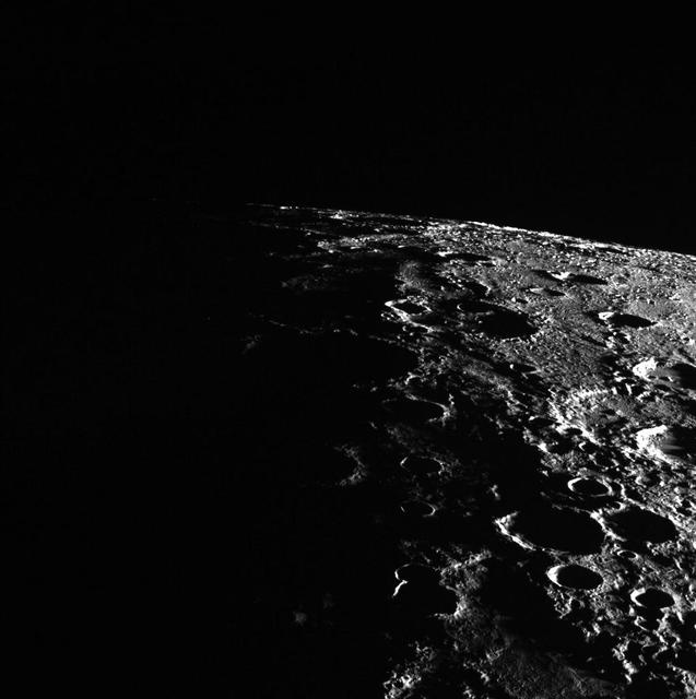
In today's image, Mercury's horizon cuts a striking edge against the stark blackness of space. On the right, sunlight harshly brings the landscape into relief while on the left, the surface is shrouded in the darkness of night. This image was acquired as part of MDIS's limb imaging campaign. Once per week, MDIS captures images of Mercury's limb, with an emphasis on imaging the southern hemisphere limb. These limb images provide information about Mercury's shape and complement measurements of topography made by the Mercury Laser Altimeter (MLA) of Mercury's northern hemisphere. Date acquired: January 20, 2015 Image Mission Elapsed Time (MET): 64084239 Image ID: 7831084 Instrument: Wide Angle Camera (WAC) of the Mercury Dual Imaging System (MDIS) WAC filter: 7 (748 nanometers) Center Latitude: -54.45° Center Longitude: 90.52° E Center Resolution: 401 meters/pixel http://photojournal.jpl.nasa.gov/catalog/PIA19192
STS109-323-035 (7 March 2002) --- Astronaut Michael J. Massimino, on the shuttle’s robotic arm, prepares to install the Electronic Support Module (ESM) in the aft shroud of the Hubble Space Telescope (HST), with the assistance of astronaut James H. Newman (out of frame). The module will support a new experimental cooling system to be installed during the next day's fifth and final scheduled spacewalk of the mission. That cooling system is designed to bring the telescope's Near-Infrared Camera and Multi-Object Spectrometer (NICMOS) back to life.
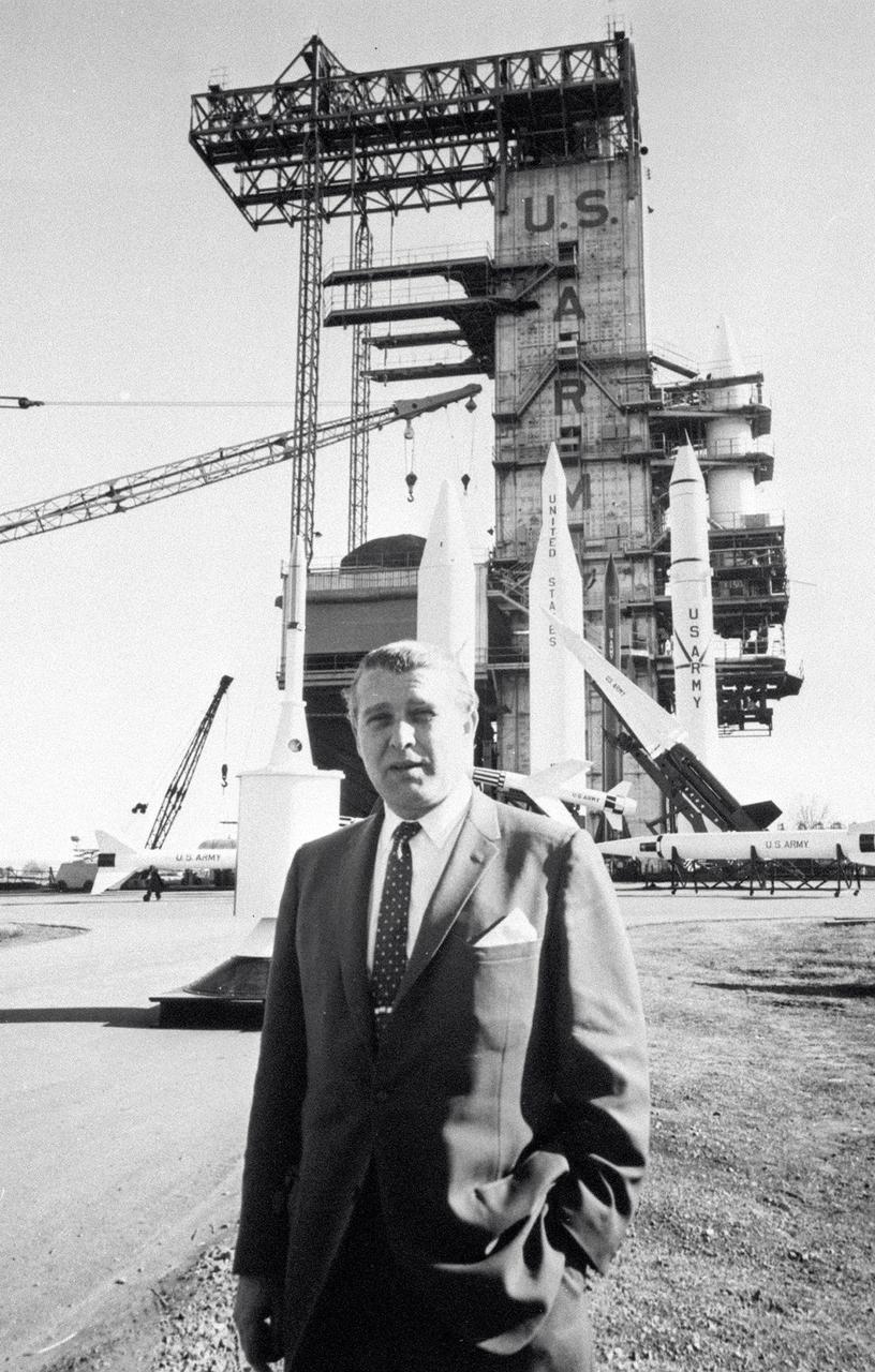
In this photo, Director of the US Army Ballistic Missile Agency (ABMA) Development Operations Division, Dr. Wernher von Braun, is standing before a display of Army missiles celebrating ABMA's Fourth Open House. The missiles in the background include (left to right) a satellite on a Juno II shroud with a Nike Ajax pointing left in front of a Jupiter missile. The Lacrosse is in front of the Juno II. The Nike Hercules points skyward in front of the Juno II and the Redstone.
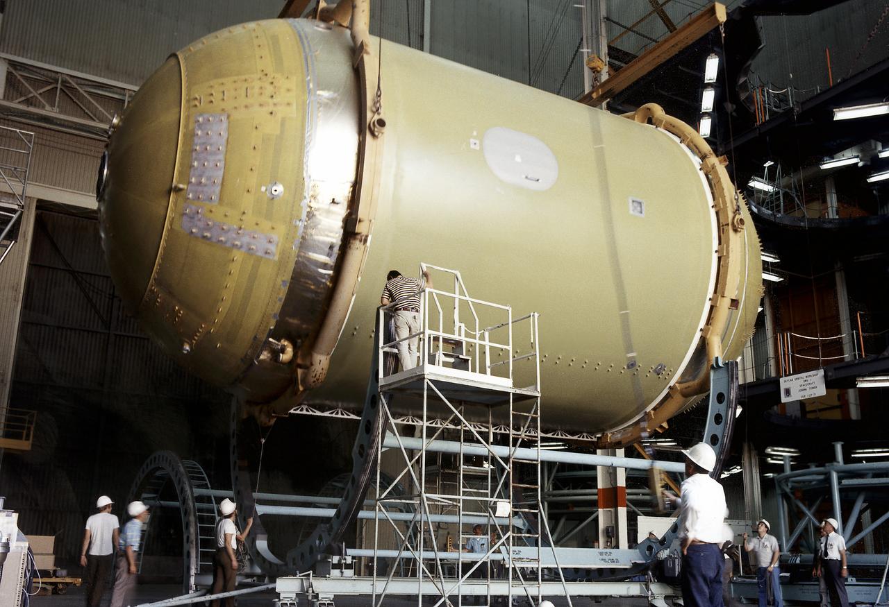
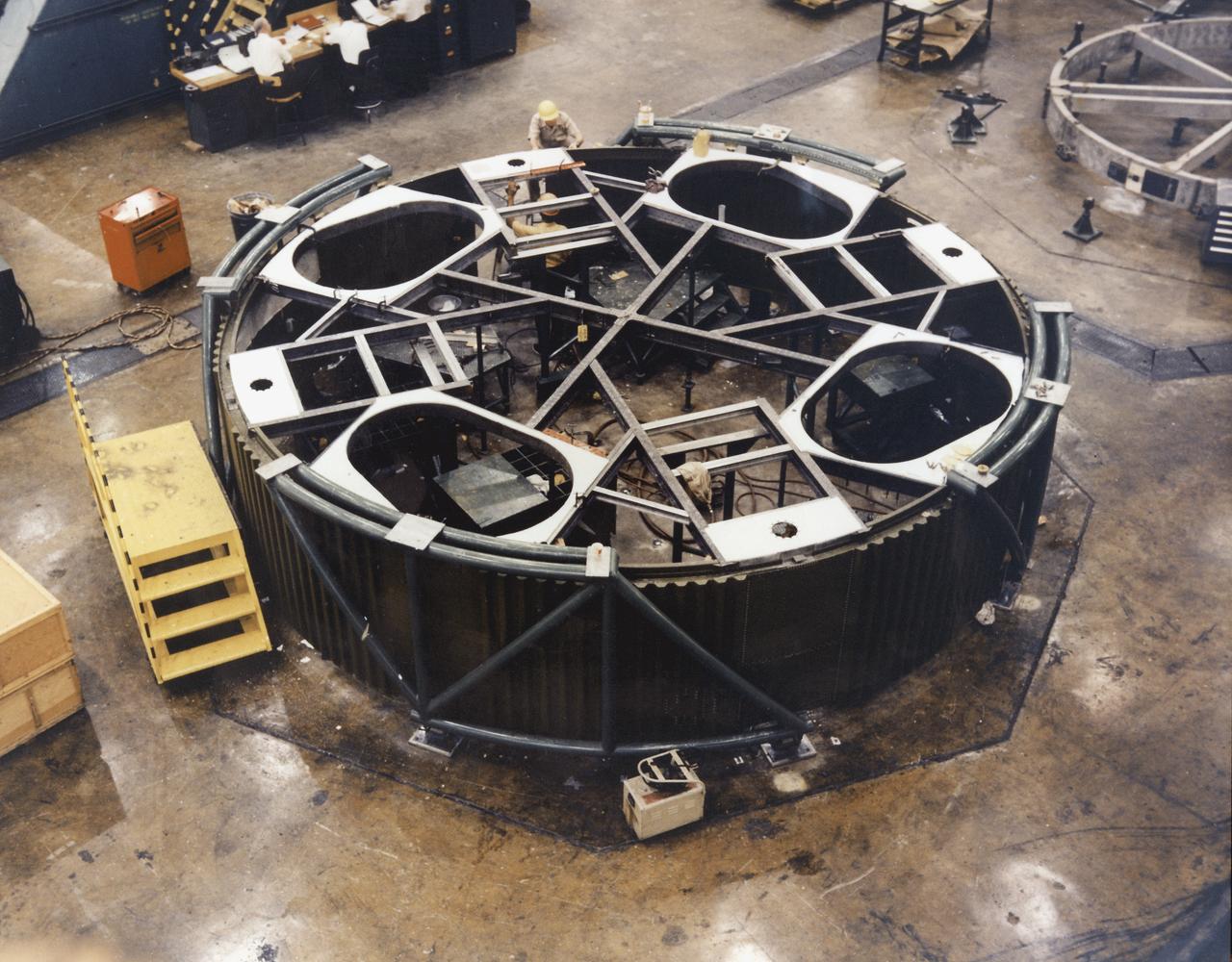
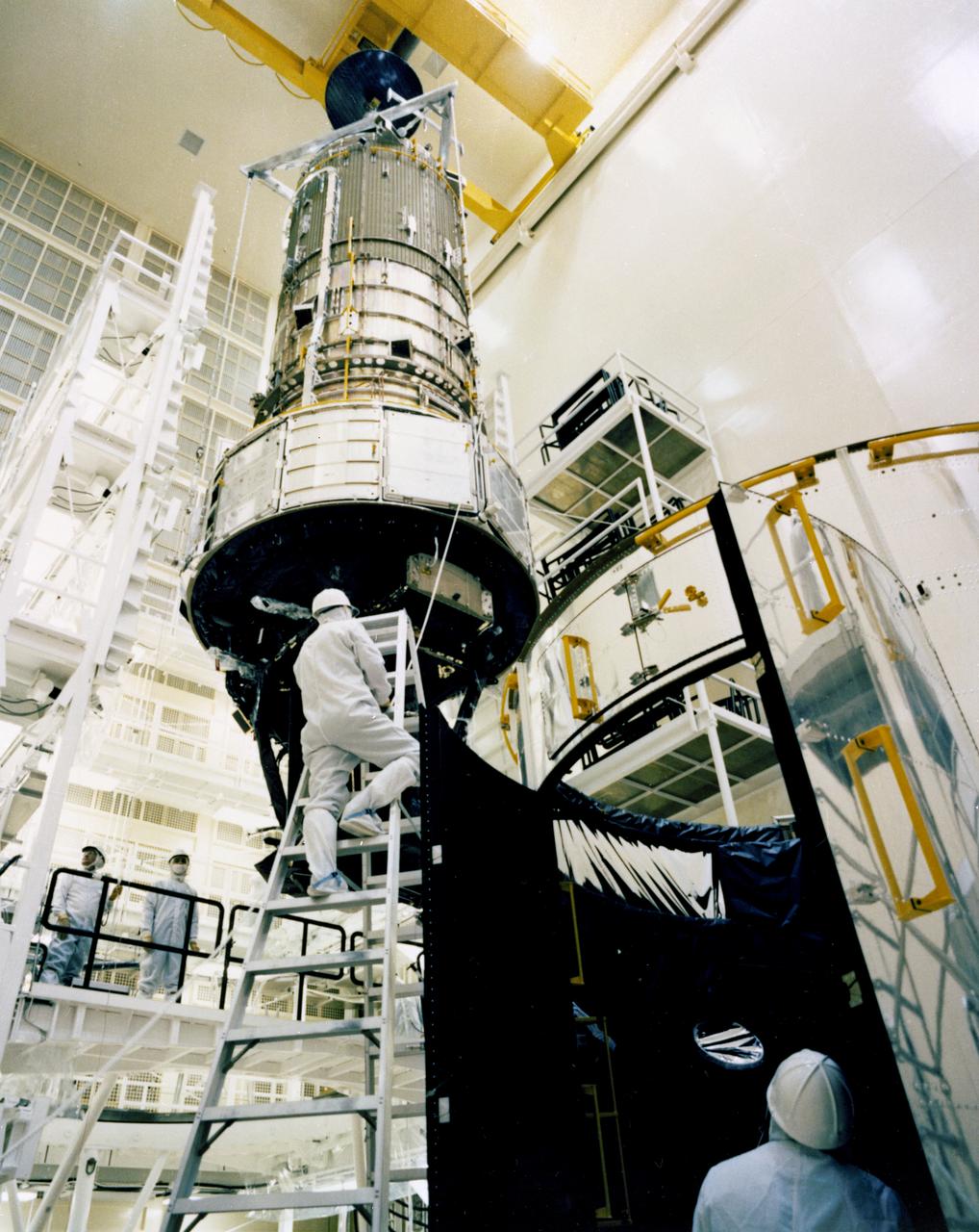
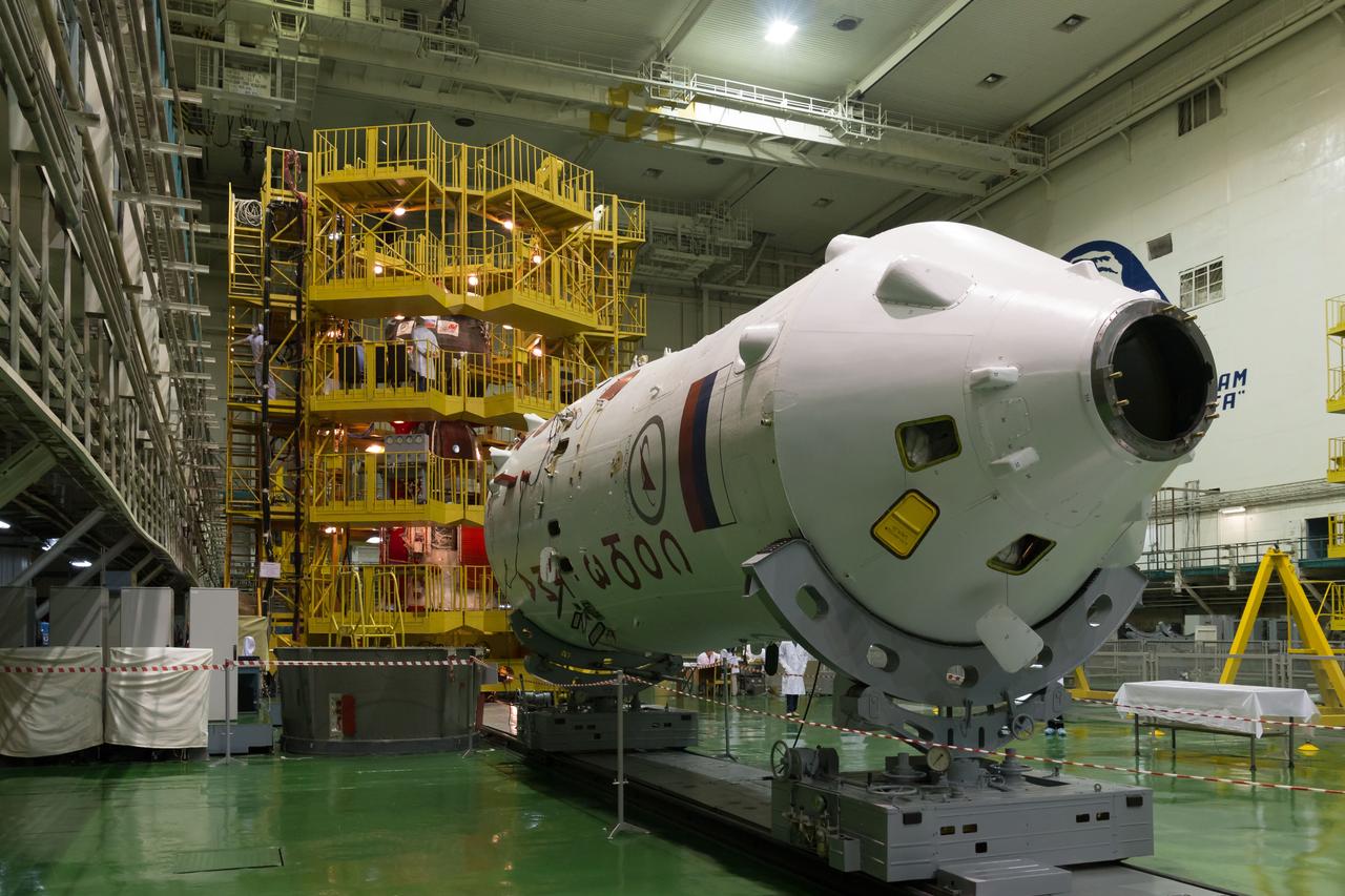
This photographs shows technicians positioning the Skylab Orbital Workshop (OWS) on a rotating work dolly during the assembly phase of the OWS at the McDornell Douglas facility in California. The OWS was the living and working quarters for the astronauts. The Marshall Space Flight Center (MSFC) had responsibility for developing and integrating most of the major components of the Skylab: the Orbital Workshop (OWS), Airlock Module (AM), Multiple Docking Adapter (MDA), Apollo Telescope Mount (ATM), Payload Shroud (PS), and most of the experiments.
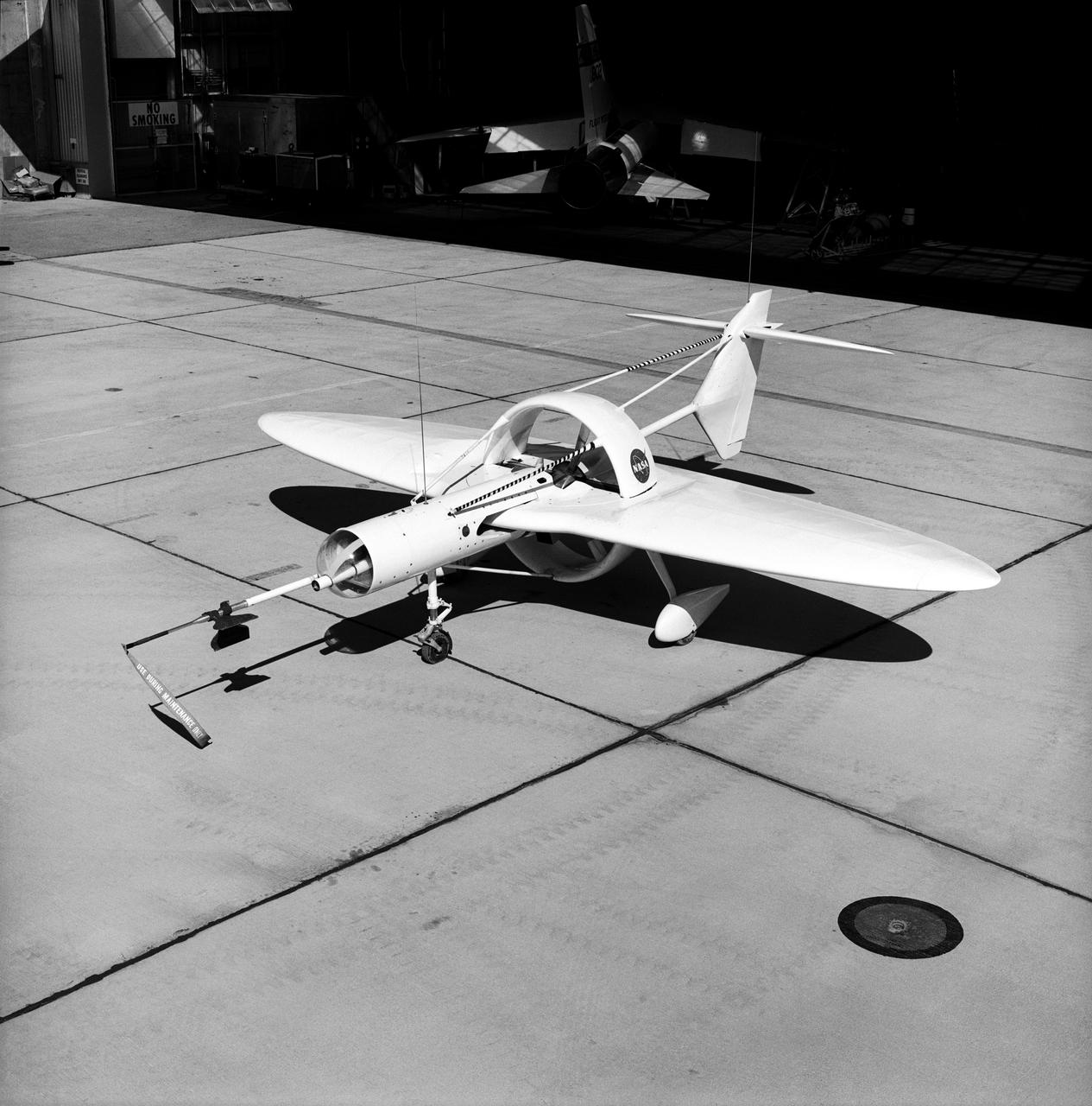
This 1976 photograph of the Oblique Wing Research Aircraft was taken in front of the NASA Flight Research Center hangar, located at Edwards Air Force Base, California. In the photograph the noseboom, pitot-static probe, and angles-of-attack and sideslip flow vanes(covered-up) are attached to the front of the vehicle. The clear nose dome for the television camera, and the shrouded propellor for the 90 horsepower engine are clearly seen.
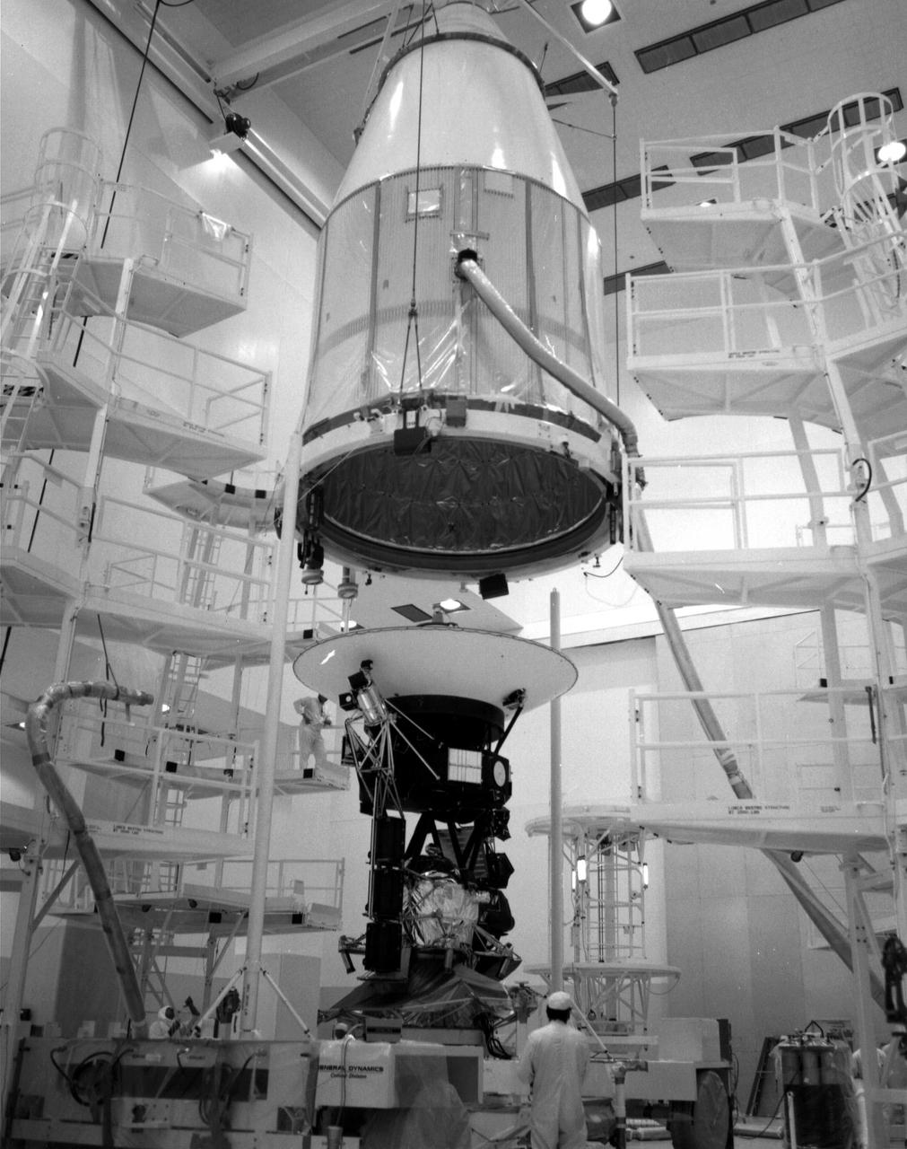
The Voyager 2 spacecraft, which was the first of the two Voyagers to launch, is seen at the Spacecraft Assembly and Encapsulation Facility-1 at NASA's Kennedy Space Center in Cape Canaveral, Florida. This archival photo is from August 1977. The spacecraft was put into this shroud on August 2, 1977, to protect it during flight through the atmosphere. https://photojournal.jpl.nasa.gov/catalog/PIA21743
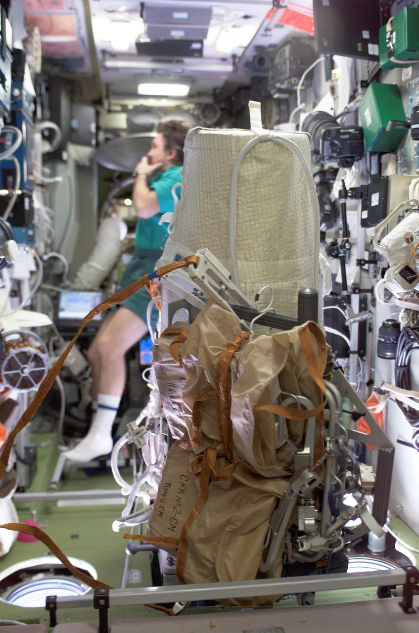
ISS008-E-17183 (24 February 2004) --- This image shows a close-up view of the extravehicular activity (EVA) bundle in the Zvezda Service Module on the International Space Station (ISS). The Matroshka experiment package is shrouded (aft) with the brown carry bags for the CKK hardware (fwd) along with tools and other needed items. It is all bundled to a Russian EVA integrated equipment carrier. Cosmonaut Alexander Y. Kaleri, flight engineer representing Russia’s Federal Space Agency, is in the background.
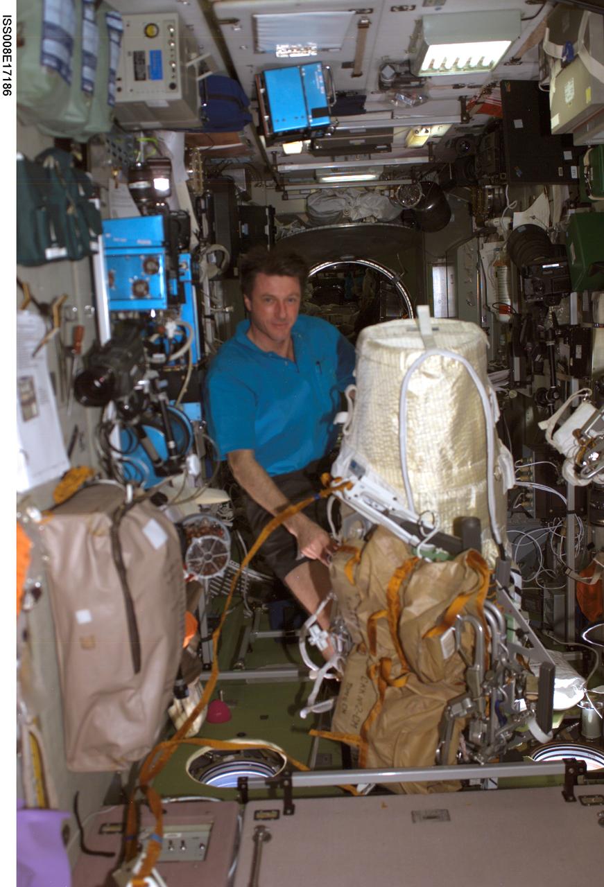
ISS008-E-17186 (24 February 2004) --- Astronaut C. Michael Foale, Expedition 8 NASA ISS science officer and commander, works with the extravehicular activity (EVA) bundle in the Zvezda Service Module on the International Space Station (ISS). The Matroshka experiment package is shrouded (aft) with the brown carry bags for the CKK hardware (fwd) along with tools and other needed items. It is all bundled to a Russian EVA integrated equipment carrier.
KENNEDY SPACE CENTER, FLA. -- The mated orbiter and lander for Viking A were encapsulated within a Centaur shroud at Spacecraft Assembly and Encapsulation Facility 2 (SAEF-2) today. The spacecraft, one of two to be launched toward Mars atop Titan_Centaurs in August, is to be moved to Launch Complex 41 on March 31 for extensive testing. KSC's Unmanned Launch Operations Directorate is scheduled to launch the twin Vikings during a 10-day period in August.
In one of the initial assembly steps for the Saturn IB launch vehicle's S-IB (first) stage, workers at the Michoud Assembly Facility (MAF) near New Orleans, Louisiana, complete the lower shroud assembly. Developed by the Marshall Space Flight Center and built by the Chrysler Corporation at Michoud Assembly Facility (MAF), the S-IB utilized the eight H-1 engines and each produced 200,000 pounds of thrust, a combined thrust of 1,600,000 pounds.
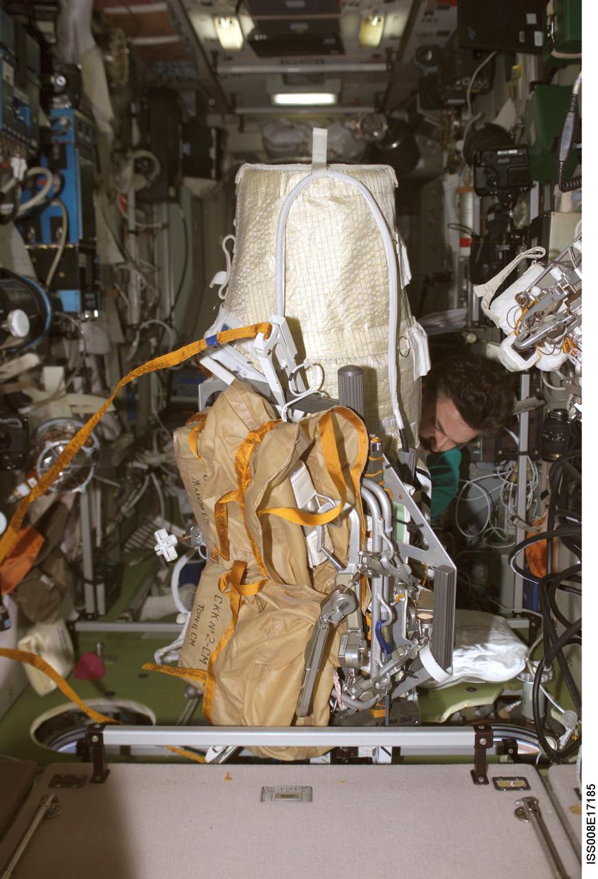
ISS008-E-17185 (24 February 2004) --- Cosmonaut Alexander Y. Kaleri, Expedition 8 flight engineer, works with the extravehicular activity (EVA) bundle in the Zvezda Service Module on the International Space Station (ISS). The Matroshka experiment package is shrouded (aft) with the brown carry bags for the CKK hardware (fwd) along with tools and other needed items. It is all bundled to a Russian EVA integrated equipment carrier. Kaleri represents Rosaviakosmos.
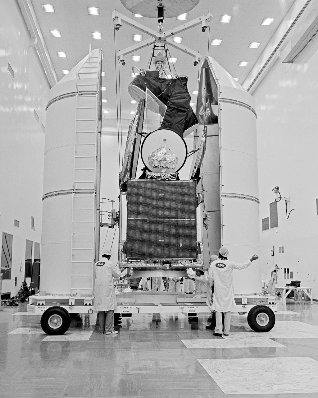
CAPE CANAVERAL, Fla. -- At Cape Canaveral Air Force Station in Florida, the INTELSAT V spacecraft is enclosed in a protective shroud for transport from Hangar AO to the Explosive Safe Facility for final servicing and encapsulation. This is the first of a new series of INTELSAT spacecraft. The INTELSAT V is the largest and highest-capacity commercial communications satellite built to date. The 4,300-pound spacecraft is scheduled for launch on an Atlas Centaur rocket from Complex 36 no earlier than December 4. It will operate in geosynchronous orbit over the Atlantic Ocean. Photo Credit: NASA
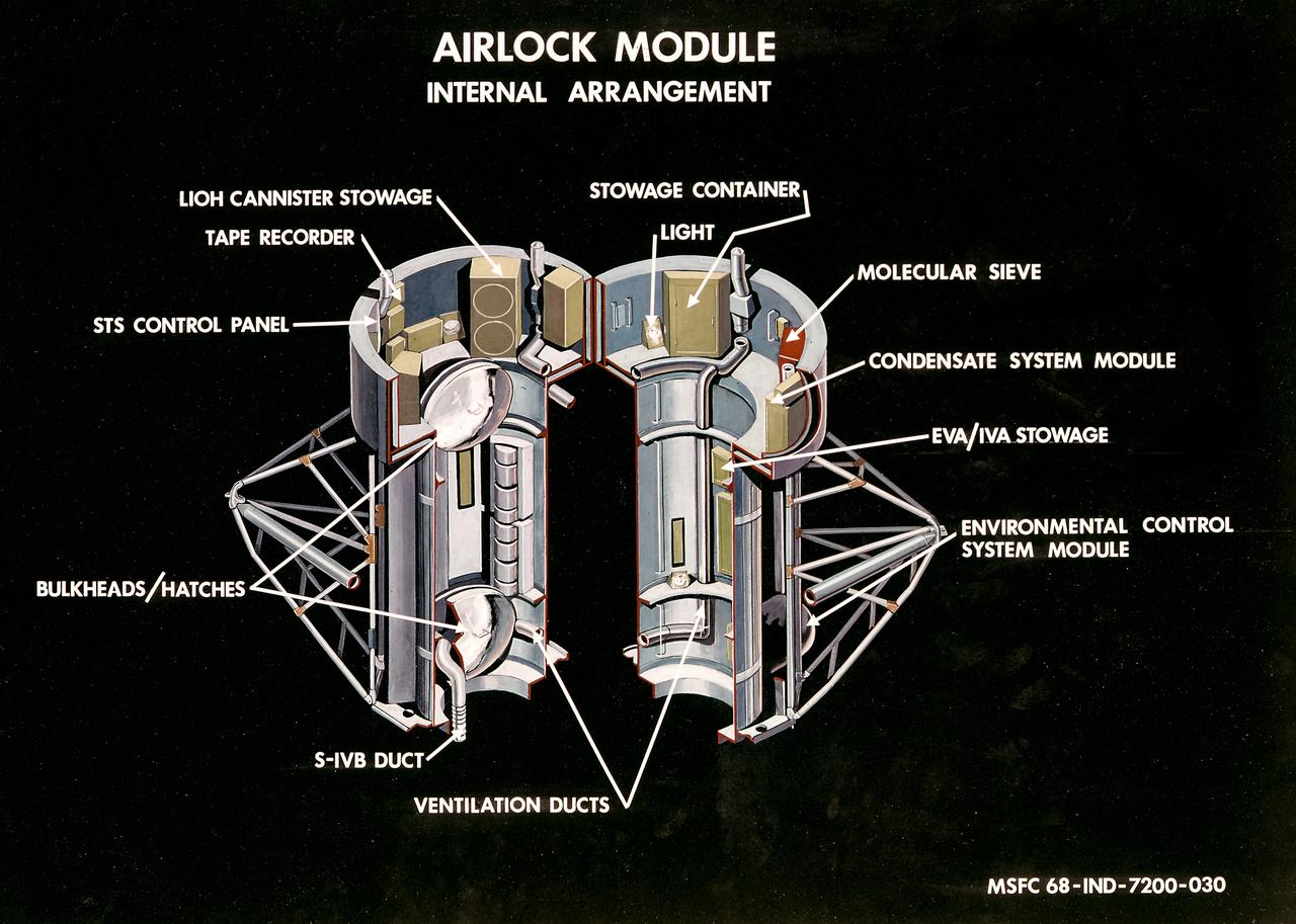
This illustration is a cutaway view of the internal arrangement of the Airlock Module (AM). The aft end of the Docking Adapter mated to the AM, and served as the environmental, electrical, and communications control center. The docking adapter also contained the port through which the astronauts exited to perform extravehicular activity. The AM contained a turnel section through which Skylab crewmen could move between the workshop and the forward end of the airlock. It was encircled, for part of its length, at its aft end by the fixed Airlock Shroud (FAS), that had the same diameter as the workshop (22 feet) and was attached to the workshop's forward end. High pressure containers for oxygen and nitrogen providing Skylab's atmosphere, were mounted in the annular space between the outside of the tunnel and the inside of the shroud. The forward end of the FAS was the base on which the tubular structure supporting the solar observatory was mounted. Many of the supplies, and most of the control systems for Skylab were located in the AM; this module could well be the "utility center" of the Skylab cluster. McDonnell Douglas fabricated the module with close Marshall Space Flight Center's involvement in design, development, and test activities.
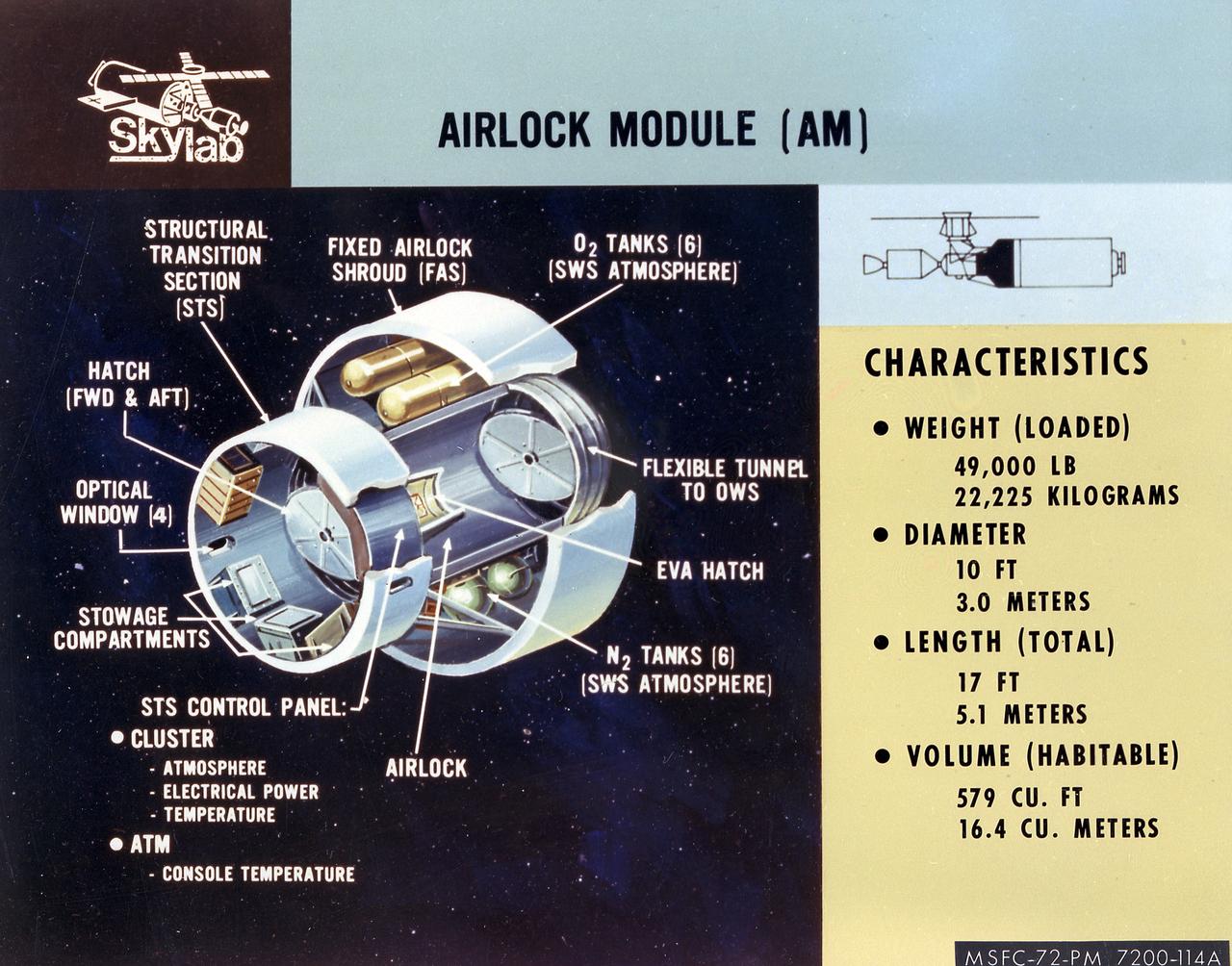
This artist's concept is a cutaway illustration of the Skylab Airlock Module and its characteristics. The aft end of the Docking Adapter mated to the Airlock Module (AM), and served as the environmental, electrical, and communications control center. The docking adapter also contained the port through which the astronauts exited to perform extravehicular activity. The AM contained a turnel section through which Skylab crewmen could move between the workshop and the forward end of the airlock. It was encircled, for part of its length, at its aft end by the fixed Airlock Shroud (FAS), that had the same diameter as the workshop (22 feet) and was attached to the workshop's forward end. High pressure containers for oxygen and nitrogen providing Skylab's atmosphere, were mounted in the annular space between the outside of the tunnel and the inside of the shroud. The forward end of the FAS was the base on which the tubular structure supporting the solar observatory was mounted. Many of the supplies, and most of the control systems for Skylab were located in the AM; this module could well be the "utility center" of the Skylab cluster. McDonnell Douglas fabricated the module with close Marshall Space Flight Center's involvement in design, development, and test activities.
This photograph shows the Hubble Space Telescope (HST) being assembled in the clean room of the Lockheed Missile Space Company. The Optical Telescope Assembly (OTA) is being readied for the installation of the AFT shroud. The OTA contains two mirrors, primary and secondary, to collect and focus light from selected celestial objects. The HST is the first of NASA's great observatories and the most complex and sensitive optical telescope ever made. The purpose of the HST is to study the cosmos from a low-Earth orbit by placing the telescope in space, enabling astronomers to collect data that is free of the Earth's atmosphere. The HST was deployed from the Space Shuttle Discovery (STS-31 mission) into Earth orbit in April 1990. The Marshall Space Flight Center had overall responsibility for design, development, and construction of the HST. The Perkin-Elmer Corporation, in Danbury, Cornecticut, developed the optical system and guidance sensors. The Lockheed Missile and Space Company, Sunnyvale, California, produced the protective outer shroud and spacecraft systems, and assembled and tested the finished telescope.
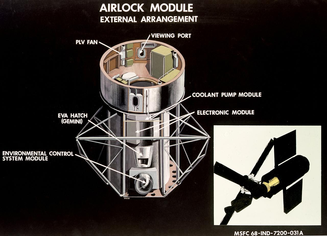
This illustration is a cutaway view of the external arrangement of the Airlock Module (AM). The aft end of the Docking Adapter mated to the AM, and served as the environmental, electrical, and communications control center. The docking adapter also contained the port through which the astronauts exited to perform extravehicular activity. The AM contained a turnel section through which Skylab crewmen could move between the workshop and the forward end of the airlock. It was encircled, for part of its length, at its aft end by the fixed Airlock Shroud (FAS), that had the same diameter as the workshop (22 feet) and was attached to the workshop's forward end. High pressure containers for oxygen and nitrogen providing Skylab's atmosphere, were mounted in the annular space between the outside of the tunnel and the inside of the shroud. The forward end of the FAS was the base on which the tubular structure supporting the solar observatory was mounted. Many of the supplies, and most of the control systems for Skylab were located in the AM; this module could well be the "utility center" of the Skylab cluster. McDonnell Douglas fabricated the module with close Marshall Space Flight Center's involvement in design, development, and test activities.

jsc2017e095968 (July 16, 2017) --- With a tree-shrouded statue of Vladimir Lenin serving as a backdrop at the Gagarin Cosmonaut Training Center in Star City, Russia, Expedition 52-53 crewmember Sergey Ryazanskiy of the Russian Federal Space Agency (Roscosmos, center) answers a reporter’s question July 16 as his crewmates, Paolo Nespoli of the European Space Agency (left) and Randy Bresnik of NASA (right) look on. The trio flew to the Baikonur Cosmodrome in Kazakhstan for final pre-launch training for their launch July 28 on the Soyuz MS-05 spacecraft and a five-month mission on the International Space Station. Credit: NASA/Beth Weissinger
CAPE CANAVERAL, Fla. – On Cape Canaveral Air Force Station's skid strip in Florida, components of the transporter are moved toward the shrouded Atlas V first stage booster on the transporter. The Atlas V is the launch vehicle for NASA's Lunar Reconnaissance Orbiter, or LRO, and NASA's Lunar CRater Observation and Sensing Satellite, known as LCROSS. The booster will be taken to the Atlas Space Operations Center on CCAFS. Launch is scheduled no earlier than May 20. LCROSS and LRO are the first missions in NASA's plan to return humans to the moon and begin establishing a lunar outpost by 2020. Photo credit: NASA/Jim Grossmann
KENNEDY SPACE CENTER, FLA. - Workers add another base plate segment to the shrouded Space Infrared Telescope Facility. The base plate is being added for the canister. SIRTF will obtain images and spectra by detecting the infrared energy, or heat, radiated by objects in space. Most of this infrared radiation is blocked by the Earth's atmosphere and cannot be observed from the ground. Consisting of an 0.85-meter telescope and three cryogenically cooled science instruments, SIRTF is one of NASA's largest infrared telescopes to be launched. SIRTF is currently scheduled for launch aboard a Delta II rocket from Launch Complex 17-B, Cape Canaveral Air Force Station.
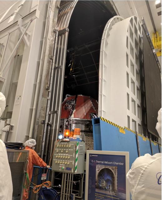
Boeing’s Crew Flight Test Starliner prepares for thermal vacuum testing at Boeing’s Space Environment Test Facility in El Segundo, Calif. During this test series, test teams outfitted Starliner with hot plates and radiators and placed in a vacuum chamber that could also be filled with a cryogenic nitrogen shroud. This allowed Boeing teams to simulate the vacuum environment in space as well as the drastic temperature swings Starliner will see as it moves to and from direct sunlight and the Earth’s shadow. This is the Starliner that will be used for Boeing’s Crew Flight Test as part of NASA’s Commercial Crew Program, which is working with Boeing to return human spaceflight launches to the space station from U.S. soil.
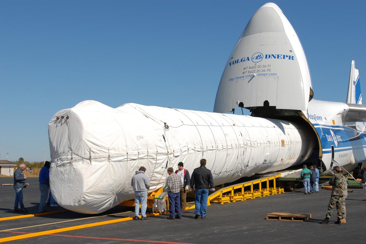
CAPE CANAVERAL, Fla. – On Cape Canaveral Air Force Station's skid strip in Florida, the shrouded Atlas V first stage booster is moved out of the Russian AH-124-100 aircraft onto a transporter. The Atlas V is the launch vehicle for NASA's Lunar Reconnaissance Orbiter, or LRO, and NASA's Lunar CRater Observation and Sensing Satellite, known as LCROSS. The booster will be taken to the Atlas Space Operations Center on CCAFS. Launch is scheduled no earlier than May 20. LCROSS and LRO are the first missions in NASA's plan to return humans to the moon and begin establishing a lunar outpost by 2020. Photo credit: NASA/Jim Grossmann
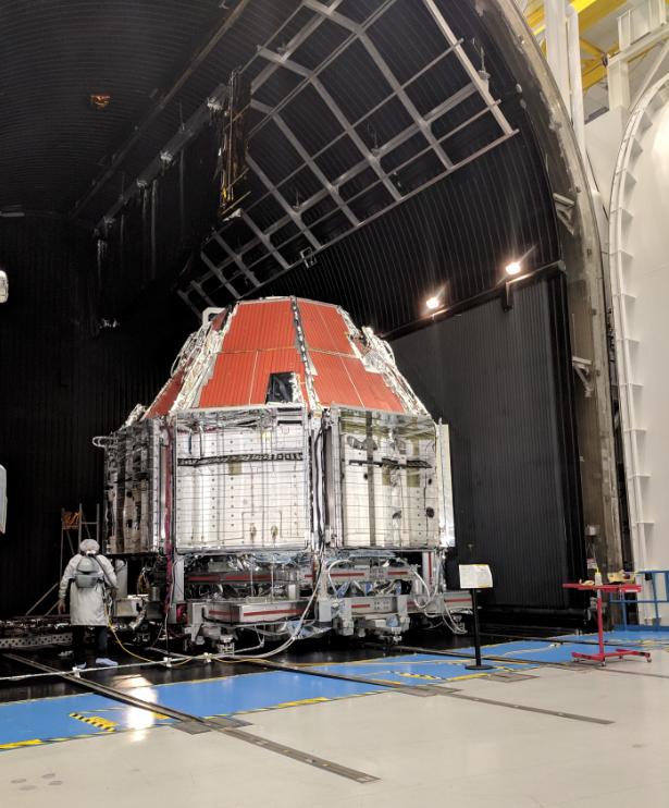
Boeing’s Crew Flight Test Starliner prepares for thermal vacuum testing at Boeing’s Space Environment Test Facility in El Segundo, Calif. During this test series, test teams outfitted Starliner with hot plates and radiators and placed in a vacuum chamber that could also be filled with a cryogenic nitrogen shroud. This allowed Boeing teams to simulate the vacuum environment in space as well as the drastic temperature swings Starliner will see as it moves to and from direct sunlight and the Earth’s shadow. This is the Starliner that will be used for Boeing’s Crew Flight Test as part of NASA’s Commercial Crew Program, which is working with Boeing to return human spaceflight launches to the space station from U.S. soil.
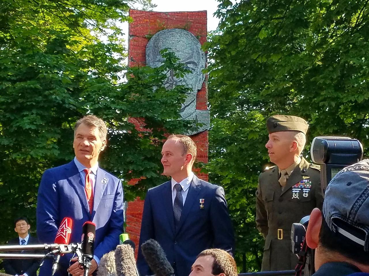
jsc2017e095972 (July 16, 2017) --- With a tree-shrouded statue of Vladimir Lenin serving as a backdrop at the Gagarin Cosmonaut Training Center in Star City, Russia, Expedition 52-53 crewmember Paolo Nespoli of the European Space Agency (left) answers a reporter’s question July 16 as his crewmates, Sergey Ryazanskiy of the Russian Federal Space Agency (Roscosmos, center) and Randy Bresnik of NASA (right) look on. The trio flew to the Baikonur Cosmodrome in Kazakhstan for final pre-launch training for their launch July 28 on the Soyuz MS-05 spacecraft and a five-month mission on the International Space Station. Credit: NASA/Beth Weissinger
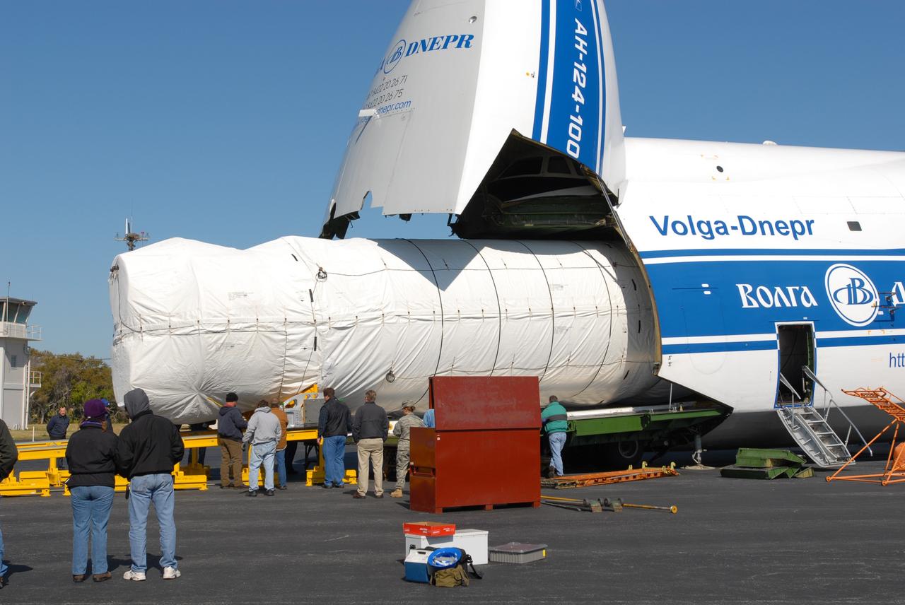
CAPE CANAVERAL, Fla. – On Cape Canaveral Air Force Station's skid strip in Florida, the shrouded Atlas V first stage booster is moved out of the Russian AH-124-100 aircraft onto a transporter. The Atlas V is the launch vehicle for NASA's Lunar Reconnaissance Orbiter, or LRO, and NASA's Lunar CRater Observation and Sensing Satellite, known as LCROSS. The booster will be taken to the Atlas Space Operations Center on CCAFS. Launch is scheduled no earlier than May 20. LCROSS and LRO are the first missions in NASA's plan to return humans to the moon and begin establishing a lunar outpost by 2020. Photo credit: NASA/Jim Grossmann
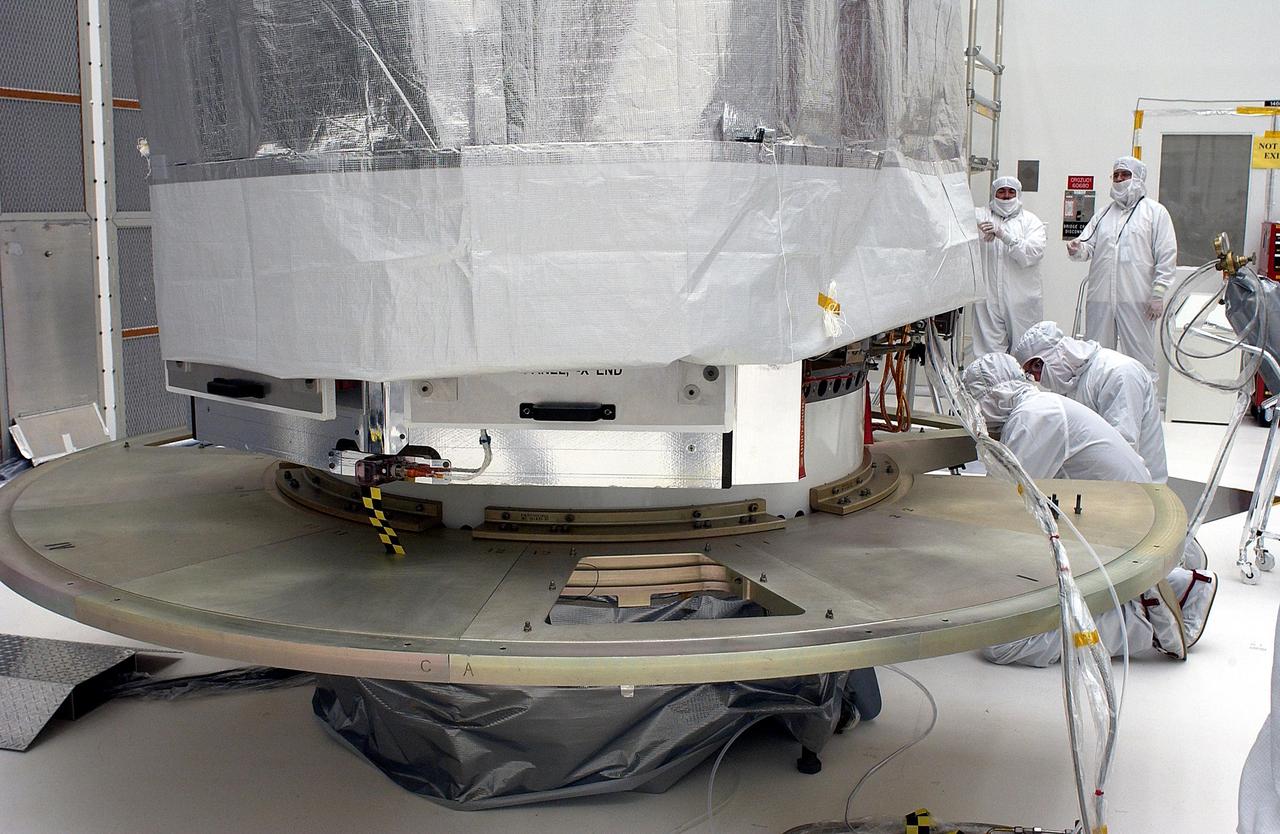
KENNEDY SPACE CENTER, FLA. - The Space Infrared Telescope Facility is shrouded while workers install the base plate segments for the canister. SIRTF will obtain images and spectra by detecting the infrared energy, or heat, radiated by objects in space. Most of this infrared radiation is blocked by the Earth's atmosphere and cannot be observed from the ground. Consisting of an 0.85-meter telescope and three cryogenically cooled science instruments, SIRTF is one of NASA's largest infrared telescopes to be launched. SIRTF is currently scheduled for launch aboard a Delta II rocket from Launch Complex 17-B, Cape Canaveral Air Force Station.

CAPE CANAVERAL, Fla. – The truck carrying the shrouded Atlas V first stage booster arrives at the Atlas Space Operations Center on CCAFS. The booster arrived at CCAFS aboard a Russian AH-124-100 aircraft. The Atlas V is the launch vehicle for NASA's Lunar Reconnaissance Orbiter, or LRO, and NASA's Lunar CRater Observation and Sensing Satellite, known as LCROSS. Launch is scheduled no earlier than May 20. LCROSS and LRO are the first missions in NASA's plan to return humans to the moon and begin establishing a lunar outpost by 2020. Photo credit: NASA/Jim Grossmann

KENNEDY SPACE CENTER, FLA. -- The Space Infrared Telescope Facility is shrouded while workers install the base plate segments for the canister. SIRTF will obtain images and spectra by detecting the infrared energy, or heat, radiated by objects in space. Most of this infrared radiation is blocked by the Earth's atmosphere and cannot be observed from the ground. Consisting of an 0.85-meter telescope and three cryogenically cooled science instruments, SIRTF is one of NASA's largest infrared telescopes to be launched. SIRTF is currently scheduled for launch aboard a Delta II rocket from Launch Complex 17-B, Cape Canaveral Air Force Station.
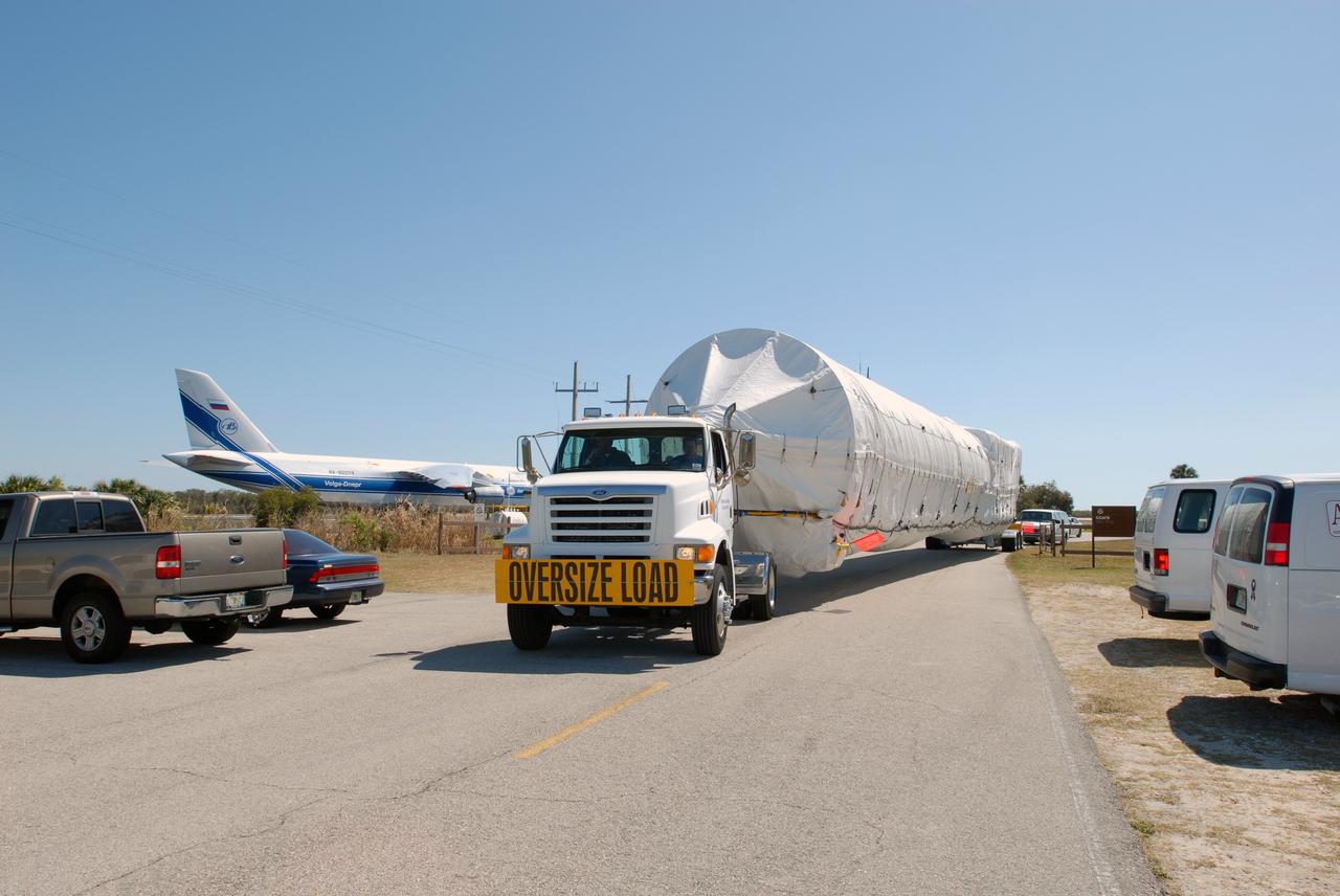
CAPE CANAVERAL, Fla. – A truck moves the shrouded Atlas V first stage booster from Cape Canaveral Air Force Station's skid strip in Florida on its way to the Atlas Space Operations Center on CCAFS. The booster arrived at CCAFS aboard a Russian AH-124-100 aircraft. The Atlas V is the launch vehicle for NASA's Lunar Reconnaissance Orbiter, or LRO, and NASA's Lunar CRater Observation and Sensing Satellite, known as LCROSS. Launch is scheduled no earlier than May 20. LCROSS and LRO are the first missions in NASA's plan to return humans to the moon and begin establishing a lunar outpost by 2020. Photo credit: NASA/Jim Grossmann
CAPE CANAVERAL, Fla. – On Cape Canaveral Air Force Station's skid strip in Florida, the shrouded Atlas V first stage booster is being prepared for its move to the Atlas Space Operations Center on CCAFS. The Atlas V is the launch vehicle for NASA's Lunar Reconnaissance Orbiter, or LRO, and NASA's Lunar CRater Observation and Sensing Satellite, known as LCROSS. Launch is scheduled no earlier than May 20. LCROSS and LRO are the first missions in NASA's plan to return humans to the moon and begin establishing a lunar outpost by 2020. Photo credit: NASA/Jim Grossmann
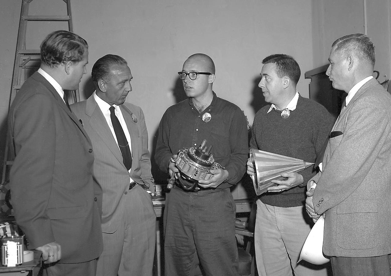
In this photo, Director of the U.S. Army Ballistic Missile Agency's (ABMA) Development Operations Division, Dr. Wernher von Braun, and Director of Missile Firing Division, Dr. Kurt Debus, are shown with unidentified individuals, discussing two components that would make up the Pioneer IV Lunar Probe. The mercury batteries (left) were used to power the radio transmitter, cosmic radiation counter and other instruments in Pioneer IV. The conical shroud placed over the instruments of Pioneer IV was plated with gold to improve conductivity. The metal surface also served as the anterna for the probe's instruments signaling back to the Earth receiving stations.
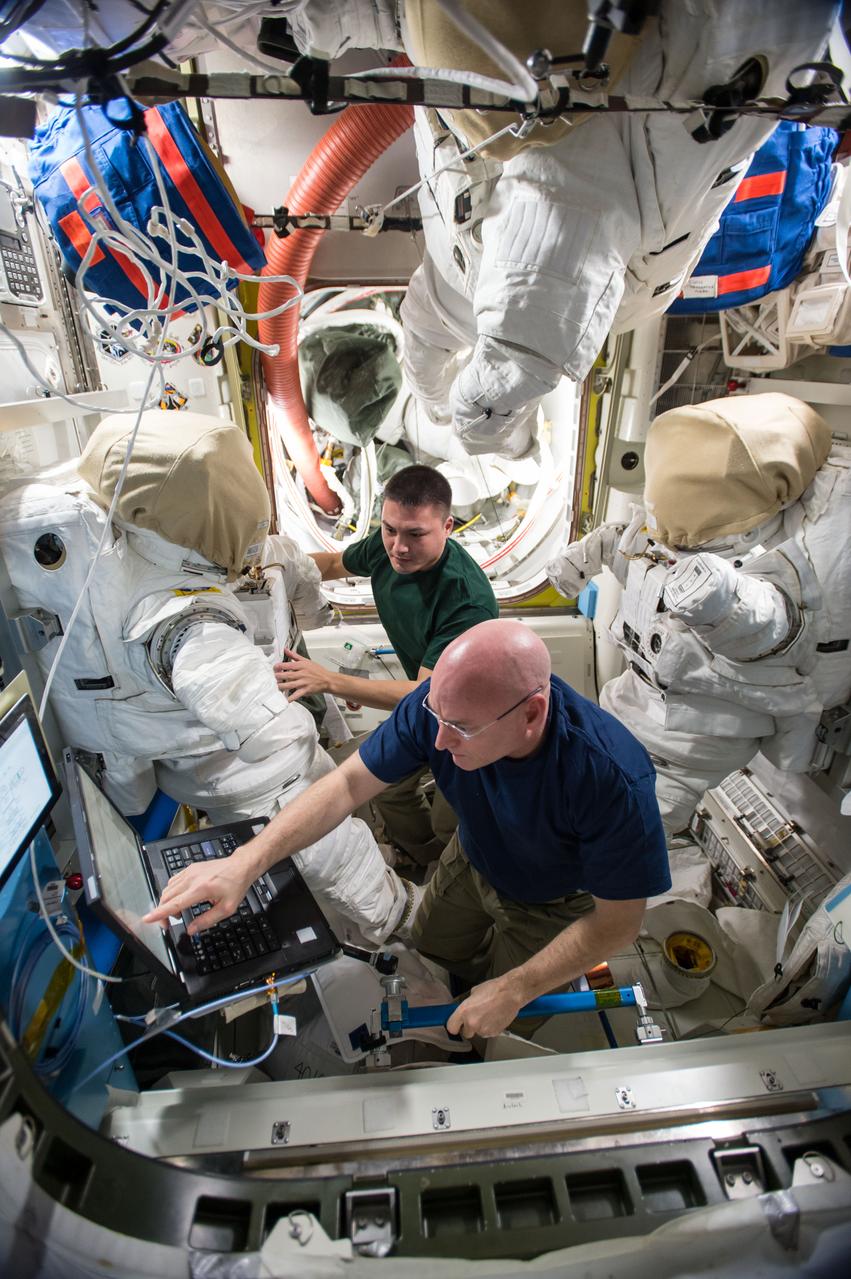
ISS045E050652 (10/07/2015) --- US astronauts Scott Kelly (bottom)and Kjell Lindgren (top) are counting down to a pair of spacewalks, now targeted for Oct. 28 and Nov. 6. The duo serviced their spacesuits replacing lithium batteries, checking their gloves and verifying power to video cameras. On the first spacewalk, the spacewalkers will lubricate the tip of the robotic arm Canadarm2, route power cables and place a thermal shroud over the Alpha Magnetic Spectrometer. During the second spacewalk, Kelly and Lindgren will refill coolant reservoirs and configure the port truss cooling system back to its original configuration after repair work completed back in 2012.
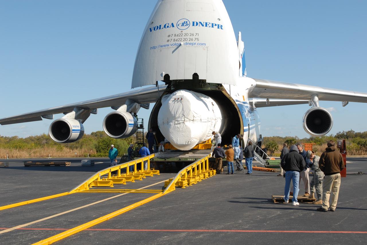
CAPE CANAVERAL, Fla. – On Cape Canaveral Air Force Station's skid strip in Florida, the shrouded Atlas V first stage booster is being moved out of the Russian AH-124-100 aircraft onto a transporter. The Atlas V is the launch vehicle for NASA's Lunar Reconnaissance Orbiter, or LRO, and NASA's Lunar CRater Observation and Sensing Satellite, known as LCROSS. The booster will be taken to the Atlas Space Operations Center on CCAFS. Launch is scheduled no earlier than May 20. LCROSS and LRO are the first missions in NASA's plan to return humans to the moon and begin establishing a lunar outpost by 2020. Photo credit: NASA/Jim Grossmann

KENNEDY SPACE CENTER, Fla. -- Space Shuttle Discovery begins rolling into the fog that shrouds Kennedy Space Center. Discovery is on its way from the Vehicle Assembly Building to Launch Pad 39B and mission STS-102 to the International Space Station. Its payload is the Multi-Purpose Logistics Module Leonardo, a “moving van,” to carry laboratory racks filled with equipment, experiments and supplies to and from the Space Station aboard the Space Shuttle. The flight will also carry the Expedition Two crew up to the Space Station, replacing Expedition One, who will return to Earth on Discovery. Launch is scheduled for March 8 at 6:45 a.m. EST
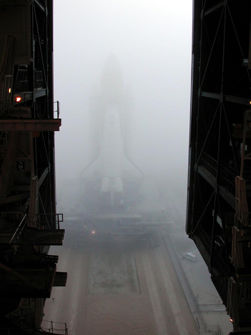
KENNEDY SPACE CENTER, Fla. -- An early morning fog that shrouds Kennedy Space Center almost renders Space Shuttle Discovery invisible as it rolls out from the Vehicle Assembly Building to Launch Pad 39B and mission STS-102 to the International Space Station. Its payload is the Multi-Purpose Logistics Module Leonardo, a “moving van,” to carry laboratory racks filled with equipment, experiments and supplies to and from the Space Station aboard the Space Shuttle. The flight will also carry the Expedition Two crew up to the Space Station, replacing Expedition One, who will return to Earth on Discovery. Launch is scheduled for March 8 at 6:45 a.m. EST
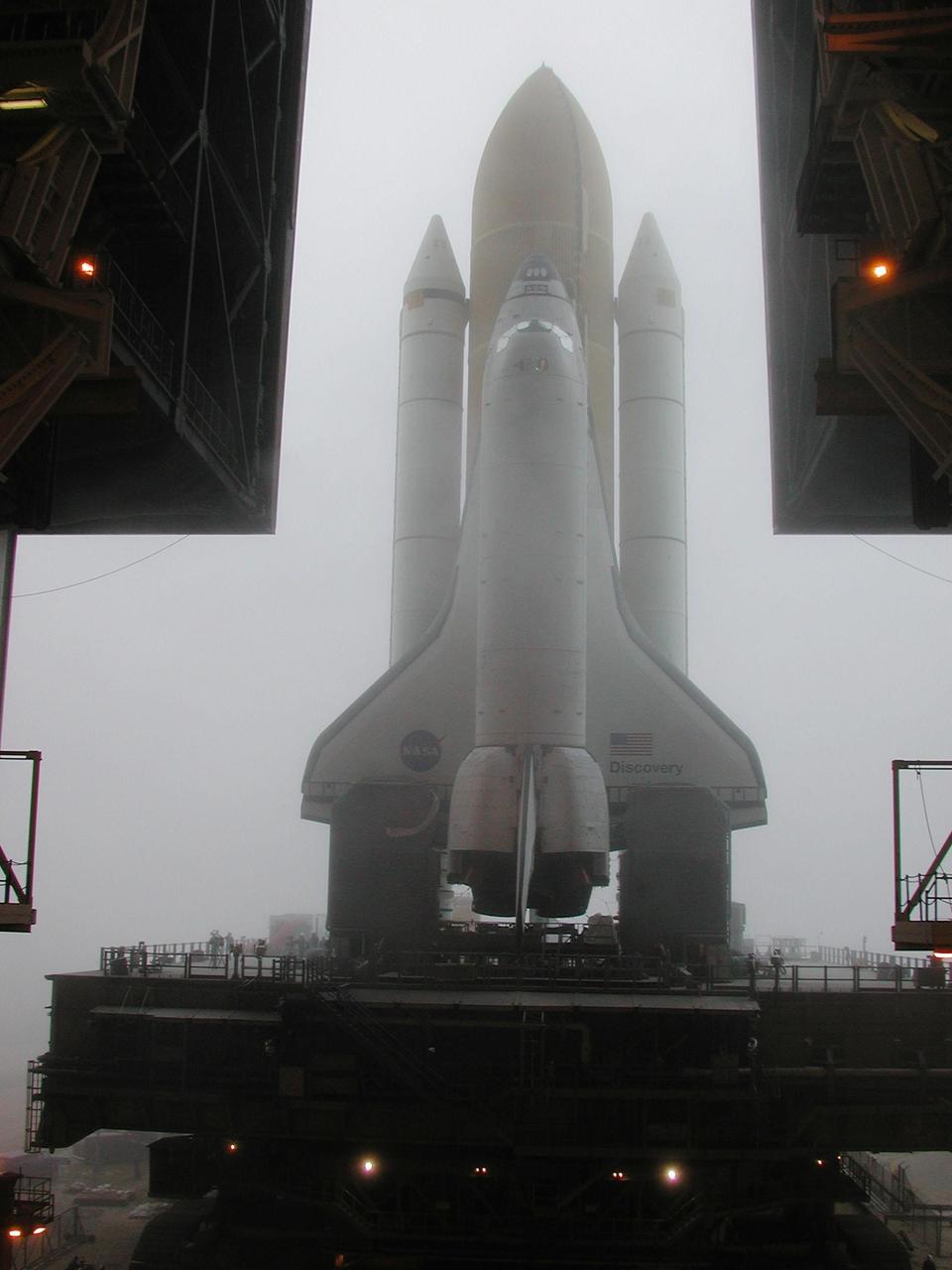
KENNEDY SPACE CENTER, Fla. -- Space Shuttle Discovery begins rolling into the fog that shrouds Kennedy Space Center. Discovery is on its way from the Vehicle Assembly Building to Launch Pad 39B and mission STS-102 to the International Space Station. Its payload is the Multi-Purpose Logistics Module Leonardo, a “moving van,” to carry laboratory racks filled with equipment, experiments and supplies to and from the Space Station aboard the Space Shuttle. The flight will also carry the Expedition Two crew up to the Space Station, replacing Expedition One, who will return to Earth on Discovery. Launch is scheduled for March 8 at 6:45 a.m. EST

KENNEDY SPACE CENTER, FLA. - Workers add another base plate segment to the shrouded Space Infrared Telescope Facility. The base plate is being added for the canister. SIRTF will obtain images and spectra by detecting the infrared energy, or heat, radiated by objects in space. Most of this infrared radiation is blocked by the Earth's atmosphere and cannot be observed from the ground. Consisting of an 0.85-meter telescope and three cryogenically cooled science instruments, SIRTF is one of NASA's largest infrared telescopes to be launched. SIRTF is currently scheduled for launch aboard a Delta II rocket from Launch Complex 17-B, Cape Canaveral Air Force Station.
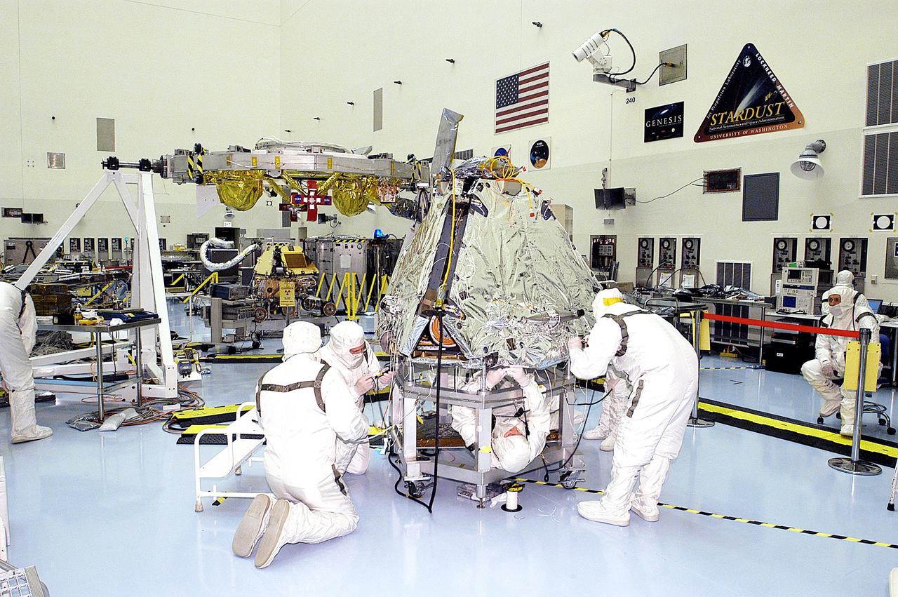
KENNEDY SPACE CENTER, FLA. - Workers prepare the shrouded Mars Exploration Rover 2 (MER-2) for mating to the lander. Set to launch in Spring 2003, the MER Mission consists of two identical rovers, landing at different regions of Mars, designed to cover roughly 110 yards each Martian day over various terrain. Each rover will carry five scientific instruments that will allow it to search for evidence of liquid water that may have been present in the planet's past. The first rover has a launch window opening May 30, and the second rover a window opening June 25.
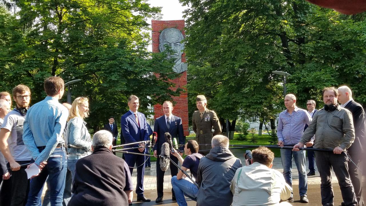
jsc2017e095967 (July 16, 2017) --- With a tree-shrouded statue of Vladimir Lenin serving as a backdrop at the Gagarin Cosmonaut Training Center in Star City, Russia, Expedition 52-53 crewmember Sergey Ryazanskiy of the Russian Federal Space Agency (Roscosmos, center) answers a reporter’s question July 16 as his crewmates, Paolo Nespoli of the European Space Agency (left) and Randy Bresnik of NASA (right) look on. The trio flew to the Baikonur Cosmodrome in Kazakhstan for final pre-launch training for their launch July 28 on the Soyuz MS-05 spacecraft and a five-month mission on the International Space Station. Credit: NASA/Beth Weissinger
11-29-53: At the Baikonur Cosmodrome in Kazakhstan, the upper stage of the Soyuz booster rocket awaits the mating of the Soyuz TMA-13M spacecraft while Expedition 40/41 Flight Engineer Alexander Gerst of the European Space Agency, Soyuz Commander Max Suraev of the Russian Federal Space Agency (Roscosmos) and NASA Flight Engineer Reid Wiseman conduct a dress rehearsal “fit check” in the Soyuz May 16 that is shrouded in the background in scaffolding. Gerst, Wiseman and Suraev will launch from Baikonur on May 29, Kazakh time, for a 5 ½ month mission on the International Space Station. NASA/Victor Zelentsov

KENNEDY SPACE CENTER, FLA. - A worker carries a base plate segment to the shrouded Space Infrared Telescope Facility. The base plate is being added for the canister. SIRTF will obtain images and spectra by detecting the infrared energy, or heat, radiated by objects in space. Most of this infrared radiation is blocked by the Earth's atmosphere and cannot be observed from the ground. Consisting of an 0.85-meter telescope and three cryogenically cooled science instruments, SIRTF is one of NASA's largest infrared telescopes to be launched. SIRTF is currently scheduled for launch aboard a Delta II rocket from Launch Complex 17-B, Cape Canaveral Air Force Station.
CAPE CANAVERAL, Fla. – On Cape Canaveral Air Force Station's skid strip in Florida, the shrouded Atlas V first stage booster has been moved out of the Russian AH-124-100 aircraft onto a transporter. The Atlas V is the launch vehicle for NASA's Lunar Reconnaissance Orbiter, or LRO, and NASA's Lunar CRater Observation and Sensing Satellite, known as LCROSS. The booster will be taken to the Atlas Space Operations Center on CCAFS.Launch is scheduled no earlier than May 20. LCROSS and LRO are the first missions in NASA's plan to return humans to the moon and begin establishing a lunar outpost by 2020. Photo credit: NASA/Jim Grossmann
Boeing’s Crew Flight Test CST-100 Starliner prepares for thermal vacuum testing at Boeing’s Space Environment Test Facility in El Segundo, Calif. During this test series, test teams outfitted Starliner with hot plates and radiators and placed in a vacuum chamber that could also be filled with a cryogenic nitrogen shroud. This allowed Boeing teams to simulate the vacuum environment in space as well as the drastic temperature swings Starliner will see as it moves to and from direct sunlight and the Earth’s shadow. This is the Starliner that will be used for Boeing’s Crew Flight Test as part of NASA’s Commercial Crew Program, which is working with Boeing to return human spaceflight launches to the space station from U.S. soil.
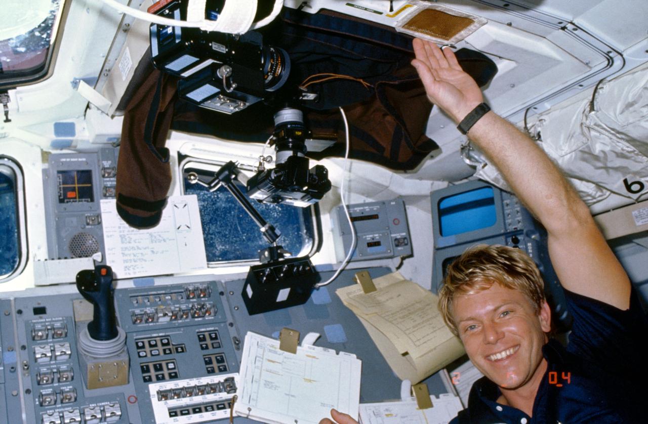
61C-05-026 (14 Jan. 1986) --- Astronaut George D. Nelson smiles for a fellow crew man's 35mm camera exposure while participating in the Comet Halley active monitoring program (CHAMP). Camera equipment and a protective shroud used to eliminate all cabin light interference surround the mission specialist. This is the first of three 1986 missions which are scheduled to monitor the rare visit by the comet. The principal investigators for CHAMP are S. Alan Stern of the Laboratory for Atmospheric and Space Physics at the University of Colorado; and Dr. Stephen Mende of Lockheed Palo Alto Research Laboratory.
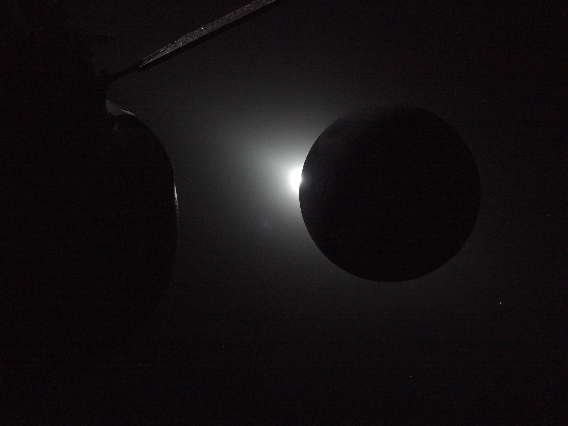
art002e009575 (April 6, 2026) - The Sun is rising at the left edge of the Moon, ending a nearly one-hour total solar eclipse on April 6, 2026. While the Sun hid behind the Moon, the crew aboard the Orion spacecraft, pictured in the forefront, saw a Moon shrouded in night. This offered a perfect opportunity to look for rarely seen phenomena. And the moment delivered. Calling down to Earth at 9 p.m. ET the crew reported seeing six impact flashes, which are light flashes that are created when meteoroids, traveling many thousands of miles per hour, smash into the Moon’s surface. Credit: NASA
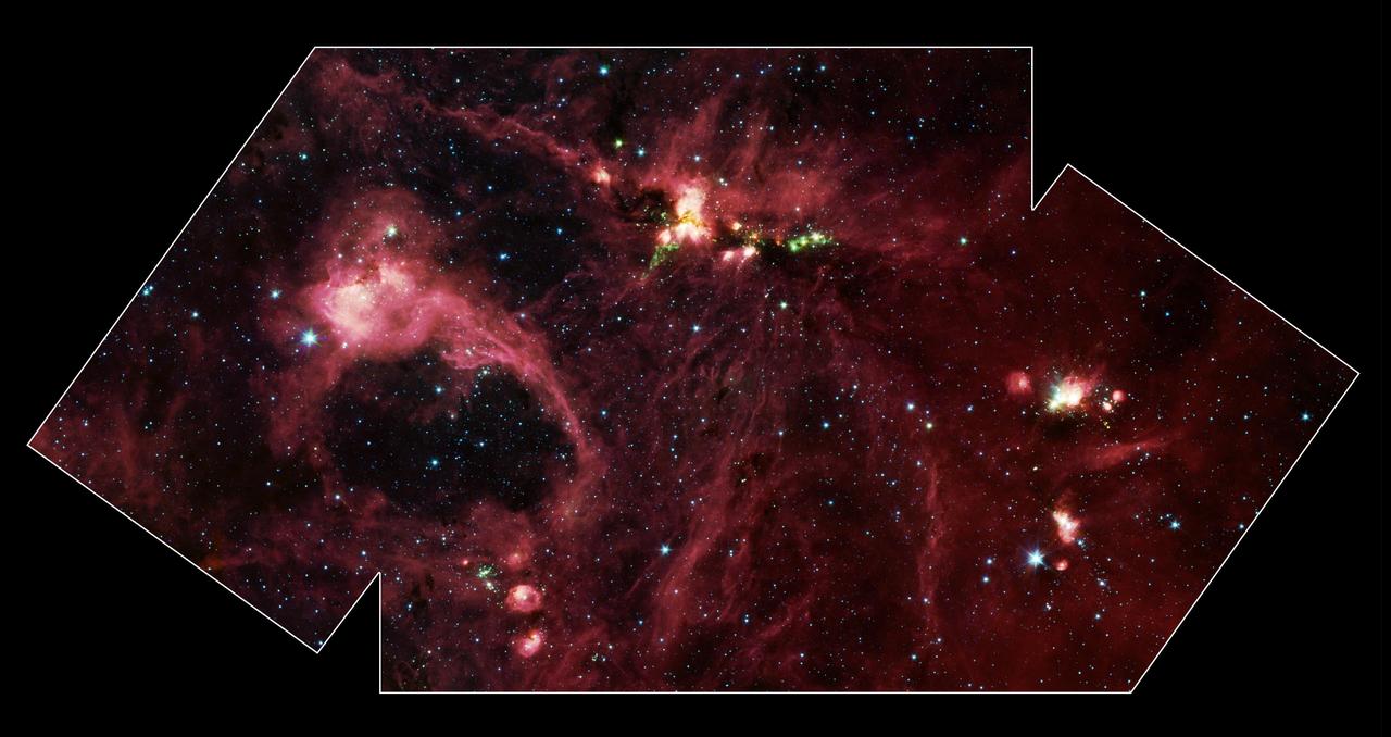
Hidden behind a shroud of dust in the constellation Cygnus is a stellar nursery called DR21, which is giving birth to some of the most massive stars in our galaxy. Visible light images reveal no trace of this interstellar cauldron because of heavy dust obscuration. In fact, visible light is attenuated in DR21 by a factor of more than 10,000,000,000,000,000,000,000,000,000,000,000,000,000 (ten thousand trillion heptillion). New images from NASA's Spitzer Space Telescope allow us to peek behind the cosmic veil and pinpoint one of the most massive natal stars yet seen in our Milky Way galaxy. The never-before-seen star is 100,000 times as bright as the Sun. Also revealed for the first time is a powerful outflow of hot gas emanating from this star and bursting through a giant molecular cloud. This image is a large-scale mosaic assembled from individual photographs obtained with the InfraRed Array Camera (IRAC) aboard Spitzer. The image covers an area about two times that of a full moon. The mosaic is a composite of images obtained at mid-infrared wavelengths of 3.6 microns (blue), 4.5 microns (green), 5.8 microns (orange) and 8 microns (red). The brightest infrared cloud near the top center corresponds to DR21, which presumably contains a cluster of newly forming stars at a distance of 10,000 light-years. Protruding out from DR21 toward the bottom left of the image is a gaseous outflow (green), containing both carbon monoxide and molecular hydrogen. Data from the Spitzer spectrograph, which breaks light into its constituent individual wavelengths, indicate the presence of hot steam formed as the outflow heats the surrounding molecular gas. Outflows are physical signatures of processes that create supersonic beams, or jets, of gas. They are usually accompanied by discs of material around the new star, which likely contain the materials from which future planetary systems are formed. Additional newborn stars, depicted in green, can be seen surrounding the DR21 region. The red filaments stretching across this image denote the presence of polycyclic aromatic hydrocarbons. These organic molecules, comprised of carbon and hydrogen, are excited by surrounding interstellar radiation and become luminescent at wavelengths near 8.0 microns. The complex pattern of filaments is caused by an intricate combination of radiation pressure, gravity and magnetic fields. The result is a tapestry in which winds, outflows and turbulence move and shape the interstellar medium. To the lower left of the mosaic is a large bubble of gas and dust, which may represent the remnants of a past generation of stars. http://photojournal.jpl.nasa.gov/catalog/PIA05732