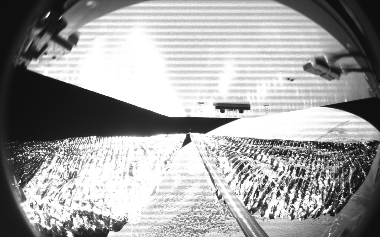
Four cameras aboard the Advanced Composite Solar Sail System spacecraft show the four reflective sail quadrants supported by composite booms. The booms are mounted at right angles and the spacecraft’s solar panel is rectangular, but lines appear distorted because of the wide-angle camera field of view. View from a black-and-white wide-angle camera aboard the Advanced Composite Solar Sail System taken during sail unfurling in low Earth orbit. The spacecraft has four such cameras, centrally located aboard the spacecraft. Here, reflective sail quadrants supported by composite booms are seen when the booms are partially extended and the sail quadrants are not taut. At the top of the photo is the back surface of one of the spacecraft’s solar panels. On the lower right Earth is seen below.
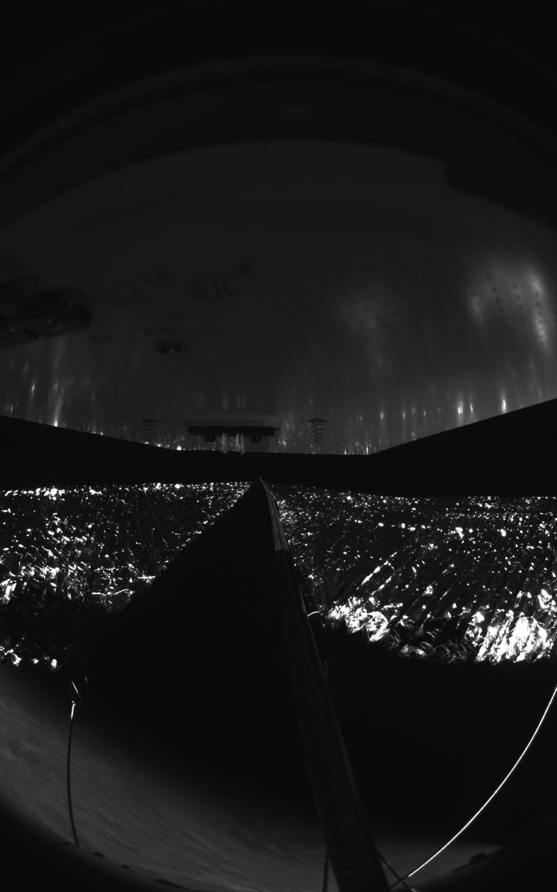
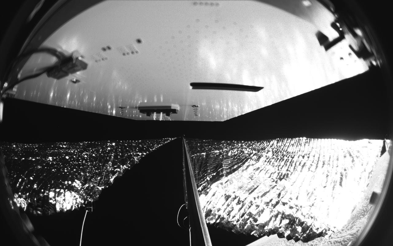
Four cameras aboard the Advanced Composite Solar Sail System spacecraft show the four reflective sail quadrants supported by composite booms. The booms are mounted at right angles and the spacecraft’s solar panel is rectangular, but lines appear distorted because of the wide-angle camera field of view. View from a black-and-white wide-angle camera aboard the Advanced Composite Solar Sail System taken during sail unfurling in low Earth orbit. The spacecraft has four such cameras, centrally located aboard the spacecraft. Here, reflective sail quadrants supported by composite booms are seen when the booms are partially extended and the sail quadrants are not taut. At the top of the photo is the back surface of one of the spacecraft’s solar panels. On the lower left Earth’s limb is seen below.
Four cameras aboard the Advanced Composite Solar Sail System spacecraft show the four reflective sail quadrants supported by composite booms. The booms are mounted at right angles and the spacecraft’s solar panel is rectangular, but lines appear distorted because of the wide-angle camera field of view. View from a black-and-white wide-angle camera aboard the Advanced Composite Solar Sail System taken during sail unfurling in low Earth orbit. The spacecraft has four such cameras, centrally located aboard the spacecraft. Here, reflective sail quadrants supported by composite booms are seen when the booms are partially extended and the sail quadrants are not taut. At the top of the photo is the back surface of one of the spacecraft’s solar panels. On the lower right Earth is seen below.

An artist’s concept of NASA’s Advanced Composite Solar Sail System spacecraft orbiting Earth, showing a configuration with solar arrays deployed and the sails and the booms stowed.
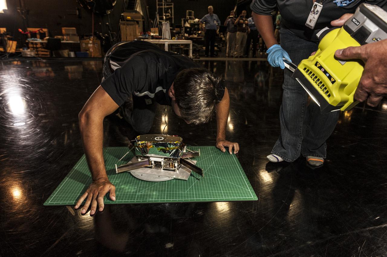
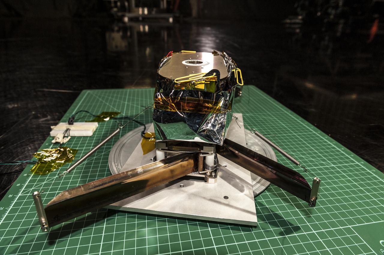
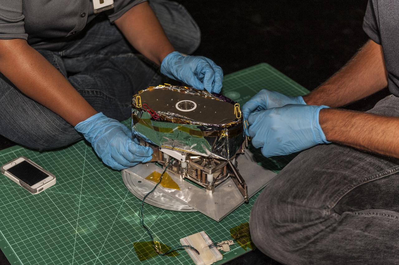
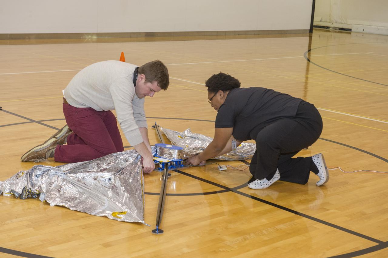
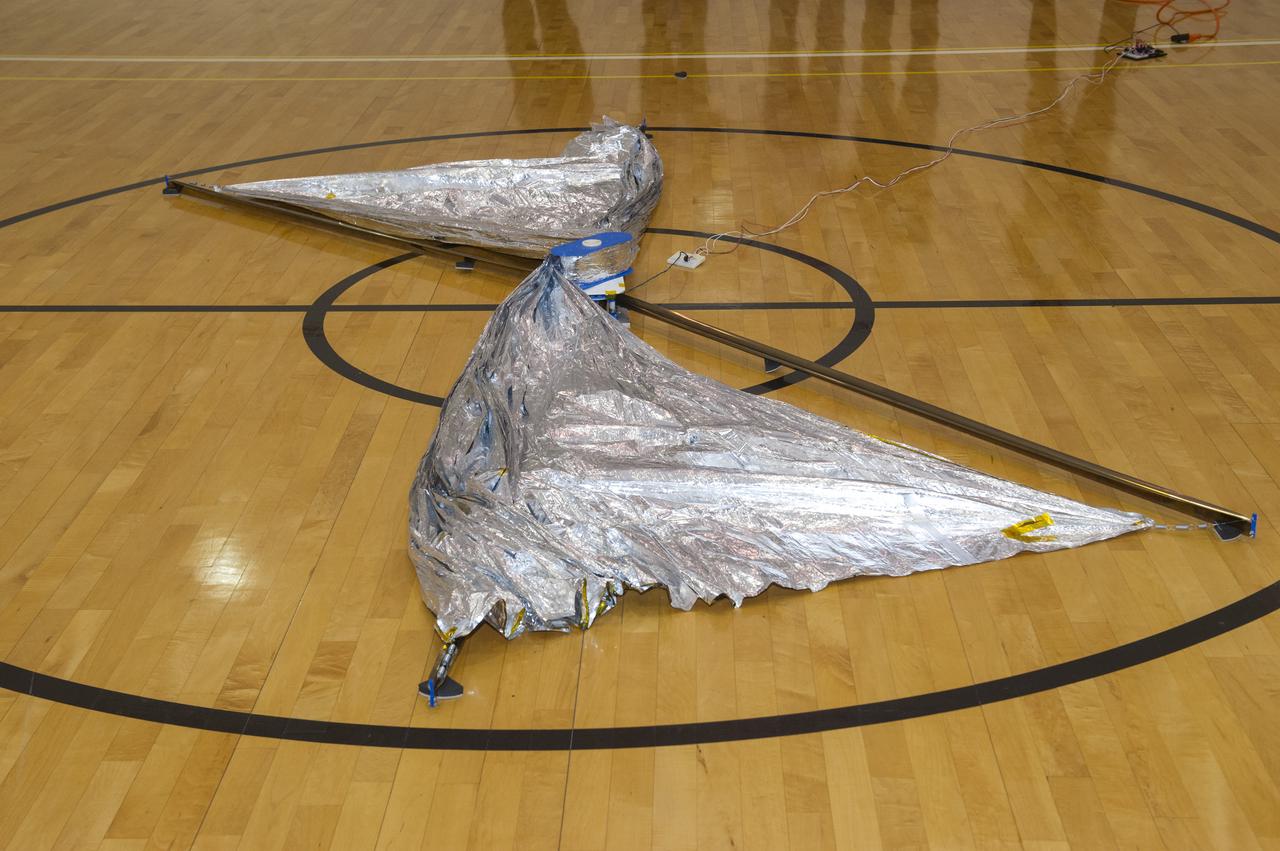
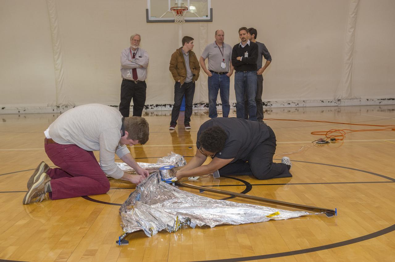
NEAR EARTH ASTEROID (NEA) SAIL TEAM PERFORMING A DEPLOYMENT OF THE FLIGHT-LIKE ENGINEERING DEVELOPMENT UNIT SOLAR SAIL. THE SAIL WAS MANUFACTURED AT NEXOLVE (HSV, AL) AND DEPLOYED FOR THE FIRST TIME AT MSFC ON AUGUST 4TH, 2016
NEAR EARTH ASTEROID (NEA) SAIL TEAM PERFORMING A DEPLOYMENT OF THE FLIGHT-LIKE ENGINEERING DEVELOPMENT UNIT SOLAR SAIL. THE SAIL WAS MANUFACTURED AT NEXOLVE (HSV, AL) AND DEPLOYED FOR THE FIRST TIME AT MSFC ON AUGUST 4TH, 2016
NEAR EARTH ASTEROID (NEA) SAIL TEAM PERFORMING A DEPLOYMENT OF THE FLIGHT-LIKE ENGINEERING DEVELOPMENT UNIT SOLAR SAIL. THE SAIL WAS MANUFACTURED AT NEXOLVE (HSV, AL) AND DEPLOYED FOR THE FIRST TIME AT MSFC ON AUGUST 4TH, 2016
NEAR EARTH ASTEROID (NEA) SAIL TEAM PERFORMING A DEPLOYMENT OF THE FLIGHT-LIKE ENGINEERING DEVELOPMENT UNIT SOLAR SAIL. THE SAIL WAS MANUFACTURED AT NEXOLVE (HSV, AL) AND DEPLOYED FOR THE FIRST TIME AT MSFC ON AUGUST 4TH, 2016
NEAR EARTH ASTEROID (NEA) SAIL TEAM PERFORMING A DEPLOYMENT OF THE FLIGHT-LIKE ENGINEERING DEVELOPMENT UNIT SOLAR SAIL. THE SAIL WAS MANUFACTURED AT NEXOLVE (HSV, AL) AND DEPLOYED FOR THE FIRST TIME AT MSFC ON AUGUST 4TH, 2016
NEAR EARTH ASTEROID (NEA) SAIL TEAM PERFORMING A DEPLOYMENT OF THE FLIGHT-LIKE ENGINEERING DEVELOPMENT UNIT SOLAR SAIL. THE SAIL WAS MANUFACTURED AT NEXOLVE (HSV, AL) AND DEPLOYED FOR THE FIRST TIME AT MSFC ON AUGUST 4TH, 2016
NEAR EARTH ASTEROID (NEA) SAIL TEAM PERFORMING A DEPLOYMENT OF THE FLIGHT-LIKE ENGINEERING DEVELOPMENT UNIT SOLAR SAIL. THE SAIL WAS MANUFACTURED AT NEXOLVE (HSV, AL) AND DEPLOYED FOR THE FIRST TIME AT MSFC ON AUGUST 4TH, 2016
NEAR EARTH ASTEROID (NEA) SAIL TEAM PERFORMING A DEPLOYMENT OF THE FLIGHT-LIKE ENGINEERING DEVELOPMENT UNIT SOLAR SAIL. THE SAIL WAS MANUFACTURED AT NEXOLVE (HSV, AL) AND DEPLOYED FOR THE FIRST TIME AT MSFC ON AUGUST 4TH, 2016
NEAR EARTH ASTEROID (NEA) SAIL TEAM PERFORMING A DEPLOYMENT OF THE FLIGHT-LIKE ENGINEERING DEVELOPMENT UNIT SOLAR SAIL. THE SAIL WAS MANUFACTURED AT NEXOLVE (HSV, AL) AND DEPLOYED FOR THE FIRST TIME AT MSFC ON AUGUST 4TH, 2016

NEAR EARTH ASTEROID (NEA) SAIL TEAM PERFORMING A DEPLOYMENT OF THE FLIGHT-LIKE ENGINEERING DEVELOPMENT UNIT SOLAR SAIL. THE SAIL WAS MANUFACTURED AT NEXOLVE (HSV, AL) AND DEPLOYED FOR THE FIRST TIME AT MSFC ON AUGUST 4TH, 2016
NEAR EARTH ASTEROID (NEA) SAIL TEAM PERFORMING A DEPLOYMENT OF THE FLIGHT-LIKE ENGINEERING DEVELOPMENT UNIT SOLAR SAIL. THE SAIL WAS MANUFACTURED AT NEXOLVE (HSV, AL) AND DEPLOYED FOR THE FIRST TIME AT MSFC ON AUGUST 4TH, 2016
NEAR EARTH ASTEROID (NEA) SAIL TEAM PERFORMING A DEPLOYMENT OF THE FLIGHT-LIKE ENGINEERING DEVELOPMENT UNIT SOLAR SAIL. THE SAIL WAS MANUFACTURED AT NEXOLVE (HSV, AL) AND DEPLOYED FOR THE FIRST TIME AT MSFC ON AUGUST 4TH, 2016
NEAR EARTH ASTEROID (NEA) SAIL TEAM PERFORMING A DEPLOYMENT OF THE FLIGHT-LIKE ENGINEERING DEVELOPMENT UNIT SOLAR SAIL. THE SAIL WAS MANUFACTURED AT NEXOLVE (HSV, AL) AND DEPLOYED FOR THE FIRST TIME AT MSFC ON AUGUST 4TH, 2016
NEAR EARTH ASTEROID (NEA) SAIL TEAM PERFORMING A DEPLOYMENT OF THE FLIGHT-LIKE ENGINEERING DEVELOPMENT UNIT SOLAR SAIL. THE SAIL WAS MANUFACTURED AT NEXOLVE (HSV, AL) AND DEPLOYED FOR THE FIRST TIME AT MSFC ON AUGUST 4TH, 2016
NEAR EARTH ASTEROID (NEA) SAIL TEAM PERFORMING A DEPLOYMENT OF THE FLIGHT-LIKE ENGINEERING DEVELOPMENT UNIT SOLAR SAIL. THE SAIL WAS MANUFACTURED AT NEXOLVE (HSV, AL) AND DEPLOYED FOR THE FIRST TIME AT MSFC ON AUGUST 4TH, 2016

This artist’s concept shows the Advanced Composite Solar Sail System spacecraft sailing in space using the energy of the Sun.

NASA’s Advanced Composite Solar Sail System is seen orbiting Earth in this 13-second exposure photograph, Monday, Sept. 2, 2024, from Arlington, Virginia. The mission team confirmed the spacecraft’s unique composite boom system unfurled its reflective sail on Thursday, accomplishing a critical milestone in the agency’s demonstration of next-generation solar sail technology that will allow small spacecraft to “sail on sunlight.” Just as a sailboat is powered by wind in a sail, a spacecraft can use the pressure of sunlight on a solar sail for propulsion. This technology demonstration serves as a pathfinder for future missions powered by solar sail technology. Photo Credit: (NASA/Bill Ingalls)

An artist's concept of NASA's Advanced Composite Solar Sail System spacecraft in orbit as the Sun crests Earth's horizon.

An artist’s concept of NASA’s Advanced Composite Solar Sail System spacecraft in Earth orbit with the Sun in the background.

An artist’s concept of NASA’s Advanced Composite Solar Sail System spacecraft in Earth orbit.
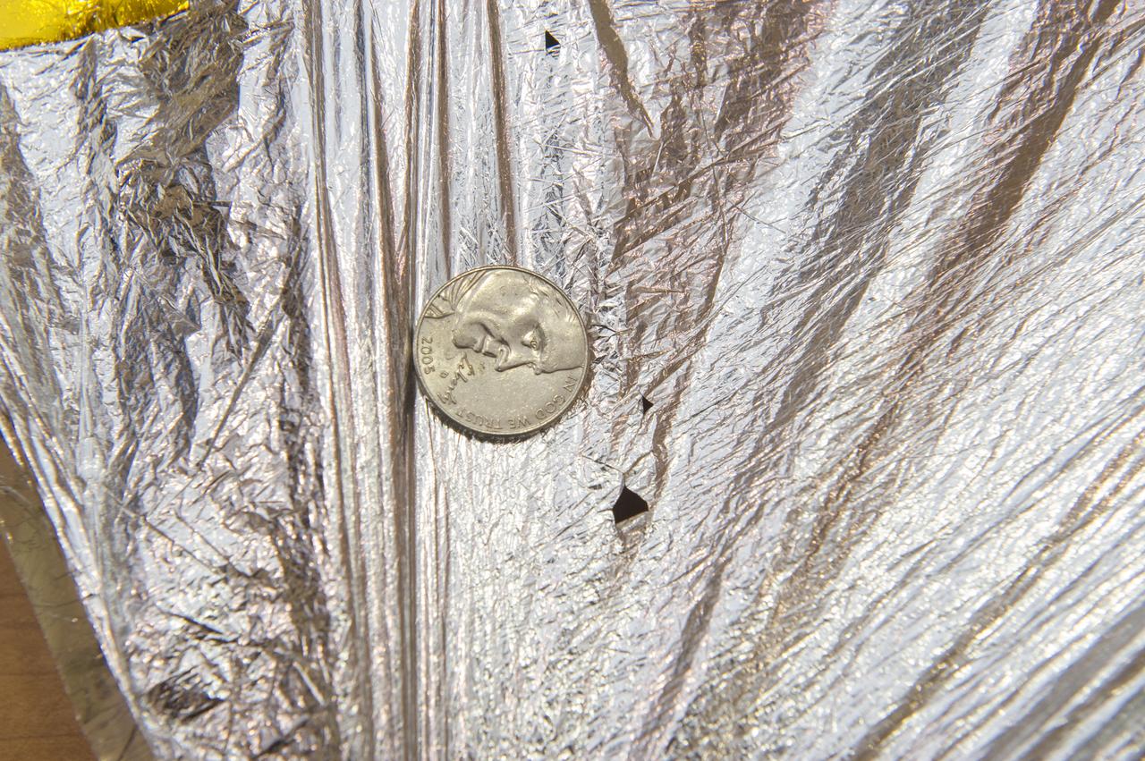
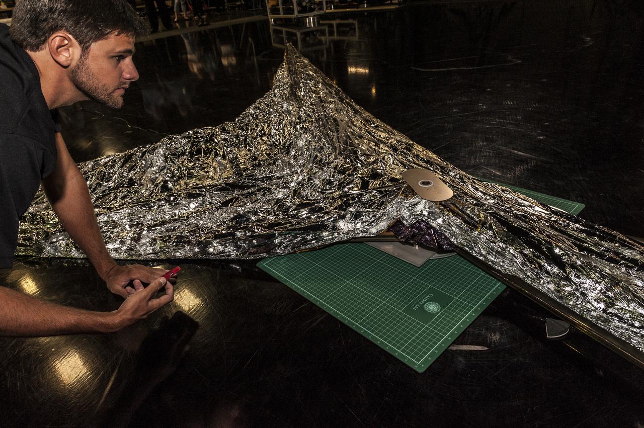
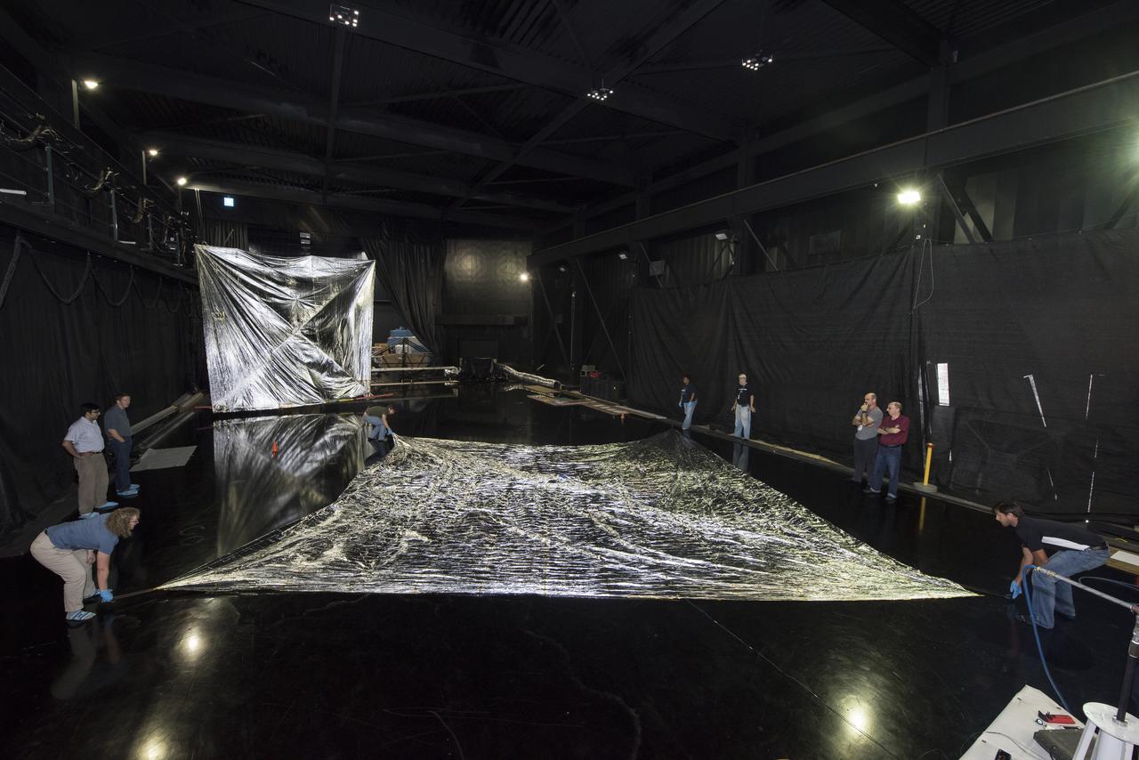
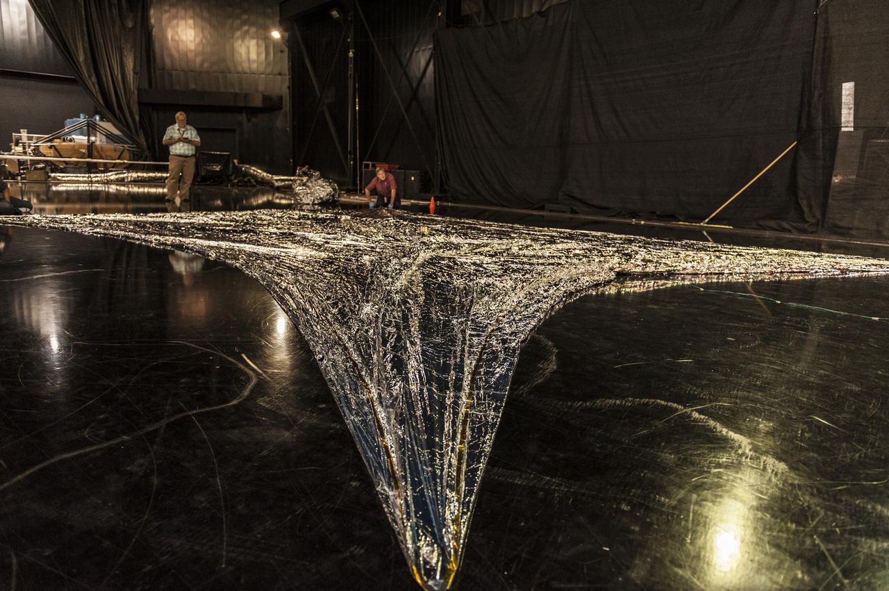
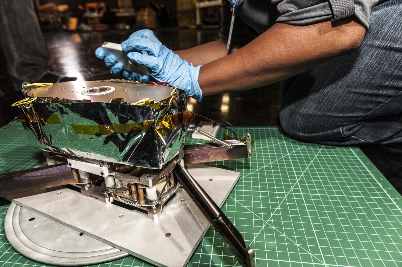
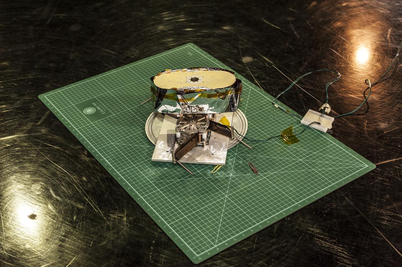
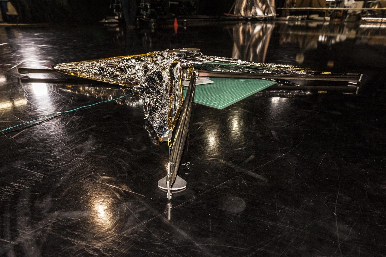
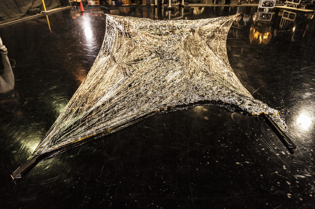
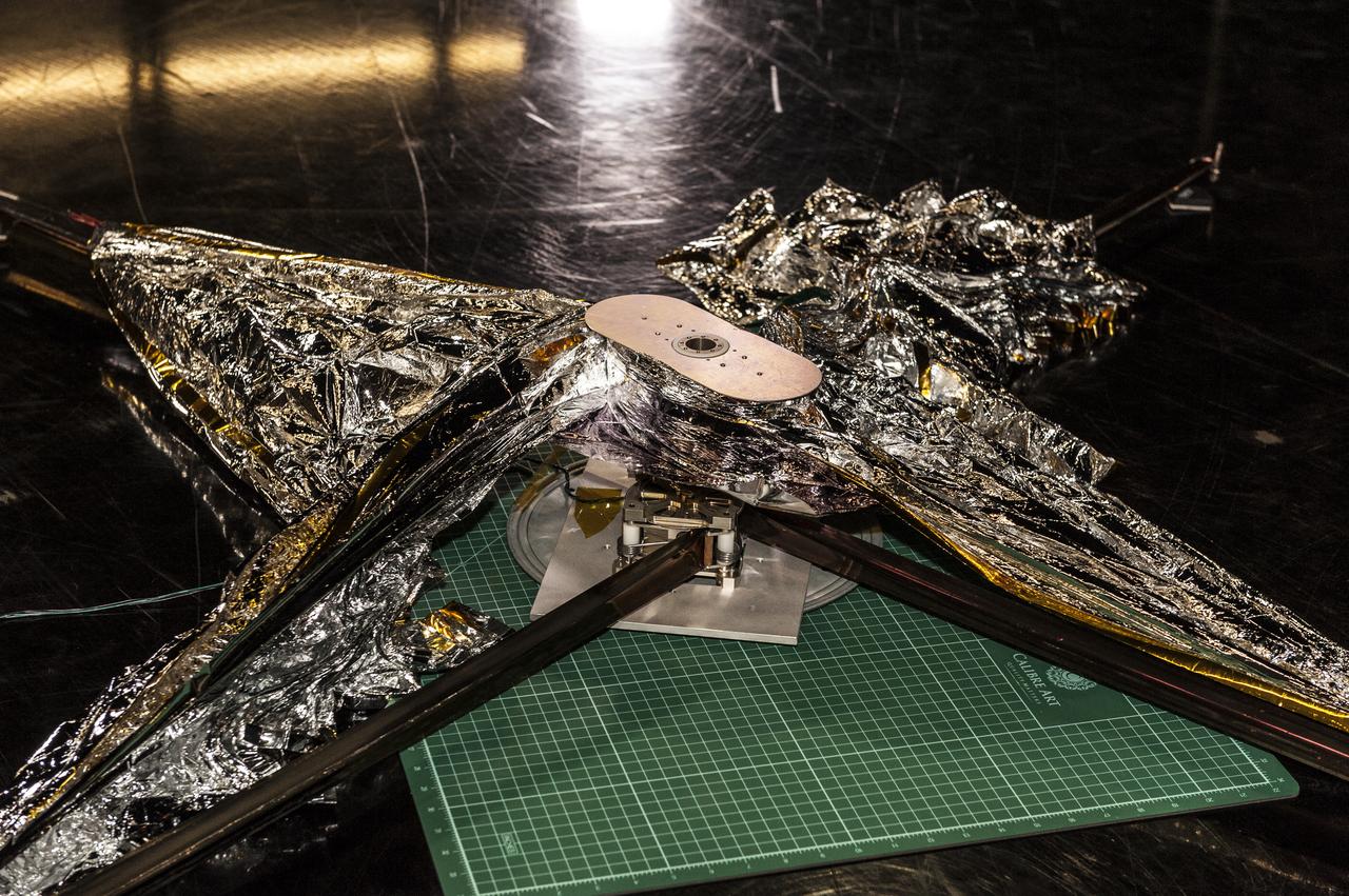
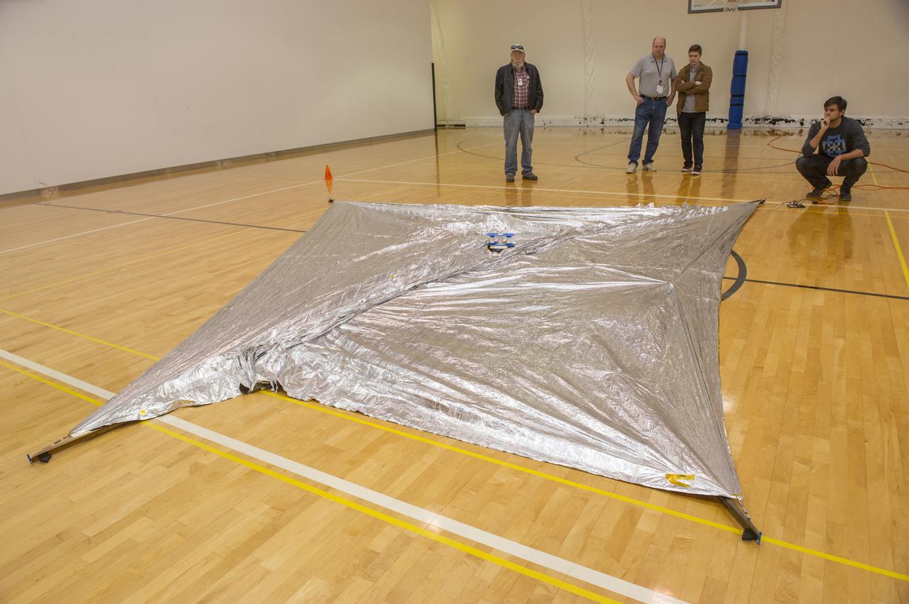
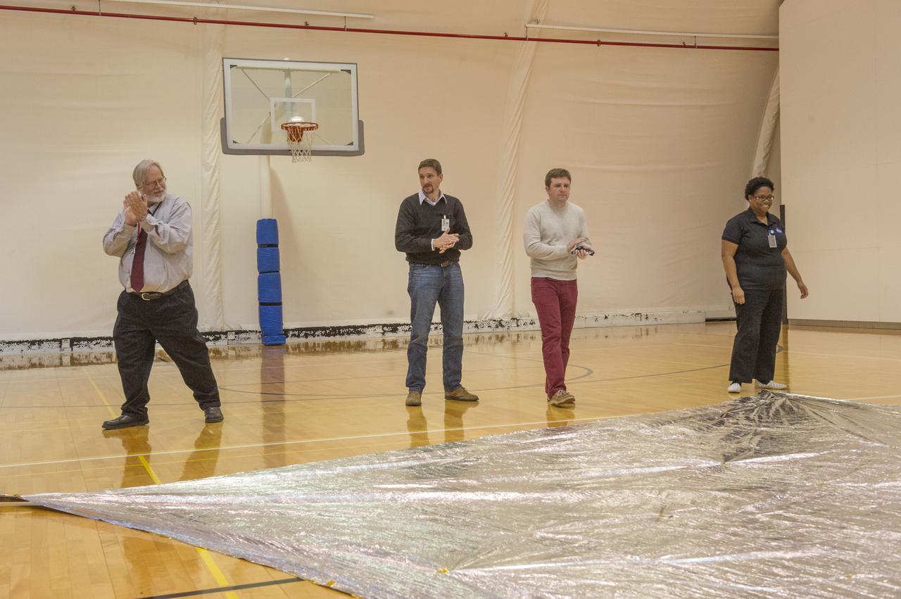
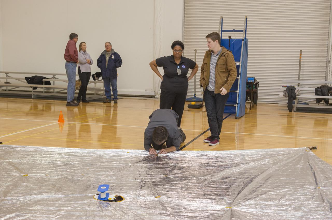
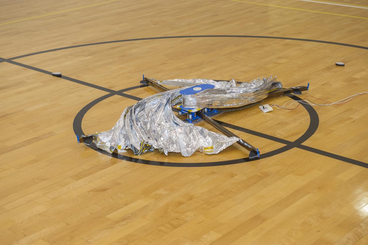
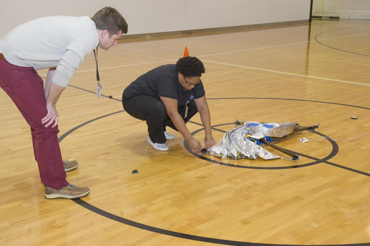
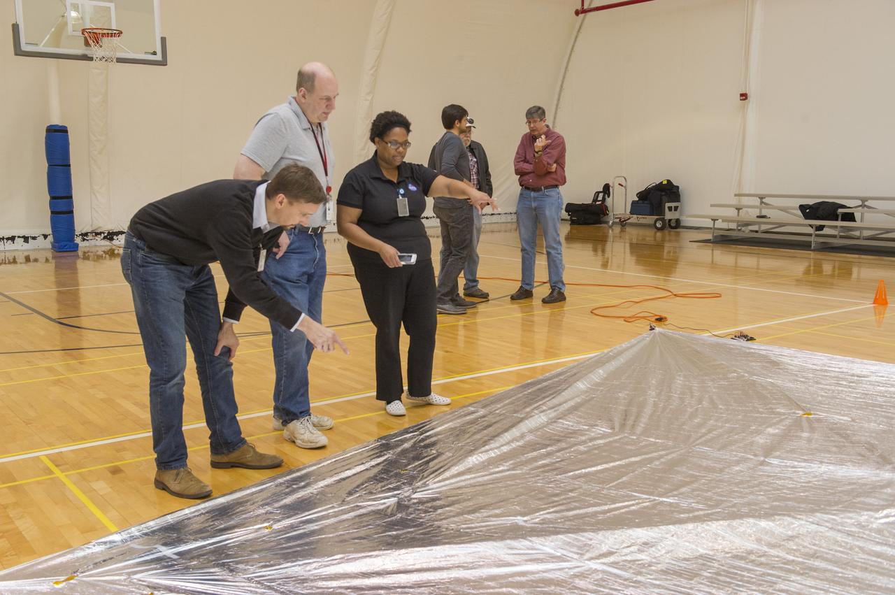
TIFFANY LOCKETT OVERSEES THE HALF SCALE (36 SQUARE METERS) ENGINEERING DEVELOPMENT UNIT (EDU) SOLAR SAIL DEPLOYMENT DEMONSTRATION IN PREPARATION FOR FULL SCALE EDU (86 SQUARE METERS) DEPLOYMENT IN APRIL, 2016. DETAILS OF RIPS AND HOLES IN SOLAR SAIL FABRIC.
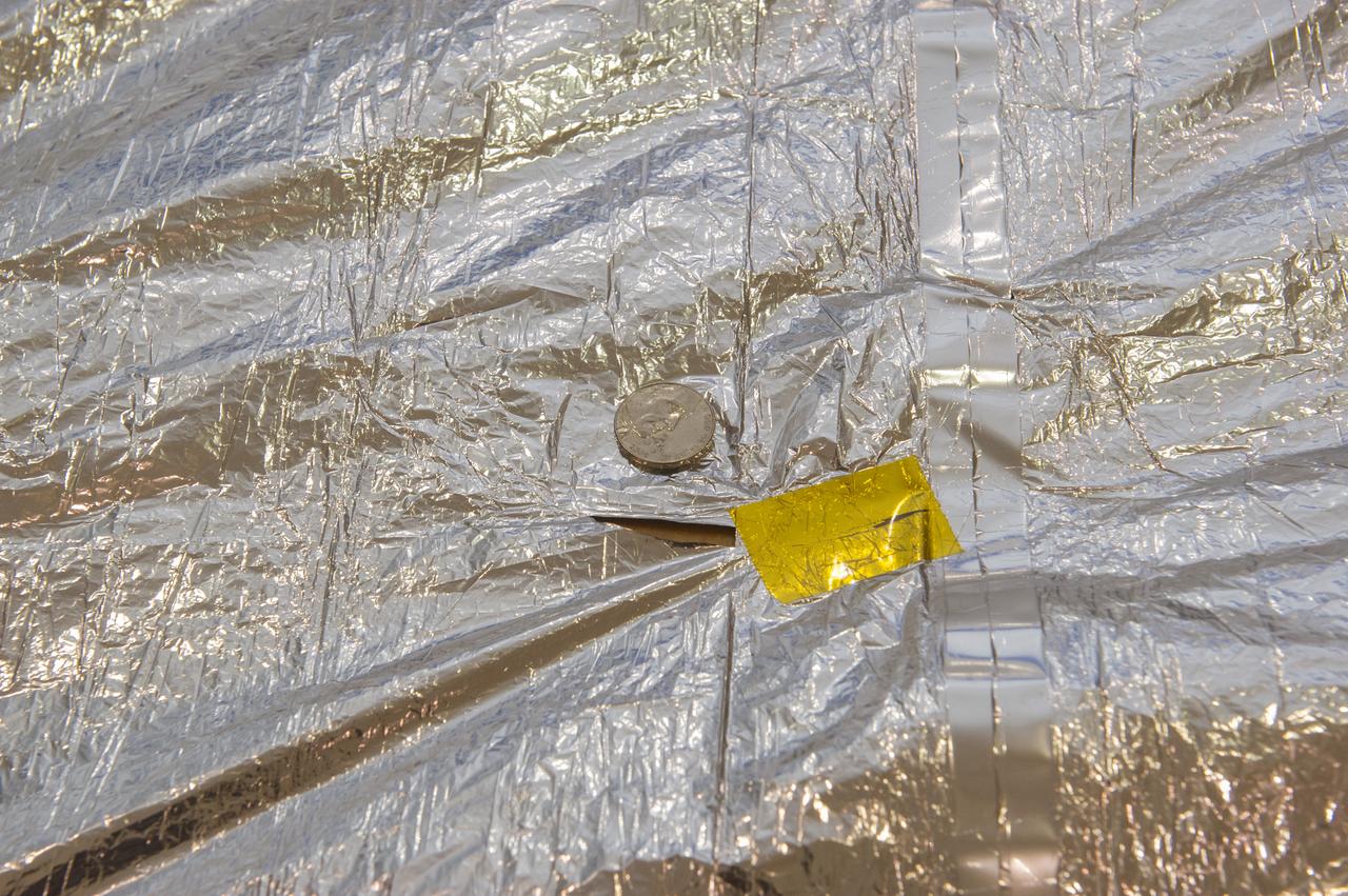
TIFFANY LOCKETT OVERSEES THE HALF SCALE (36 SQUARE METERS) ENGINEERING DEVELOPMENT UNIT (EDU) SOLAR SAIL DEPLOYMENT DEMONSTRATION IN PREPARATION FOR FULL SCALE EDU (86 SQUARE METERS) DEPLOYMENT IN APRIL, 2016. DETAILS OF RIPS AND HOLES IN SOLAR SAIL FABRIC.

An artist’s concept of NASA’s Advanced Composite Solar Sail System spacecraft in orbit as seen from directly above the spacecraft looking down at Earth below.
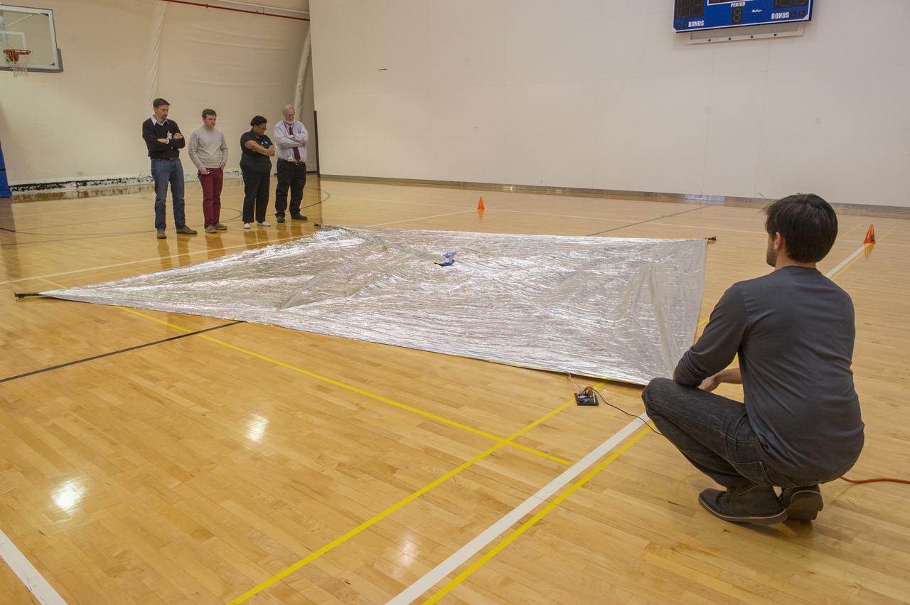
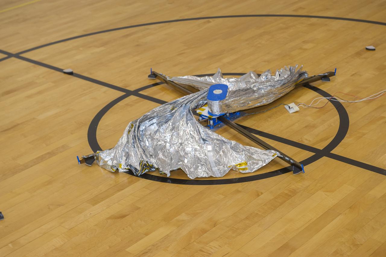
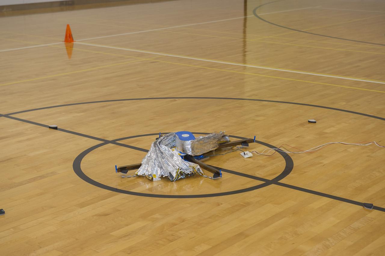
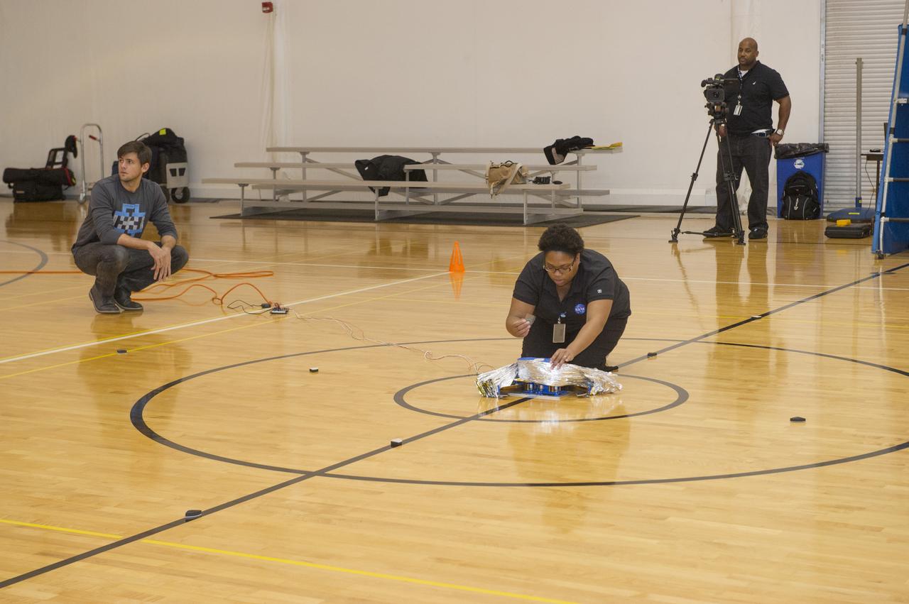
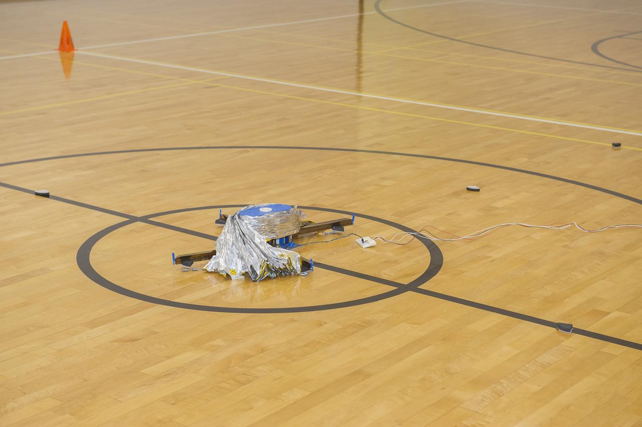
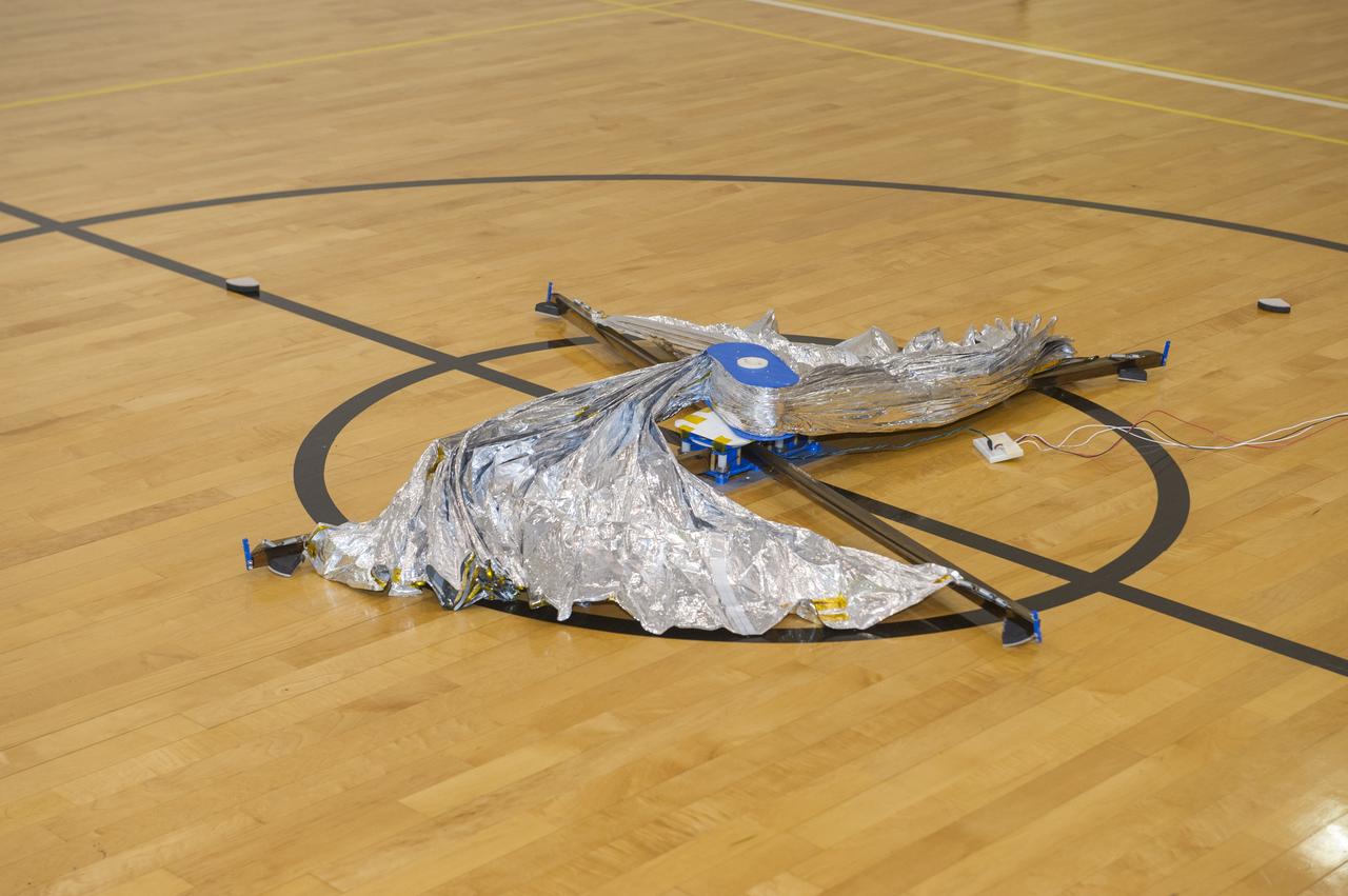
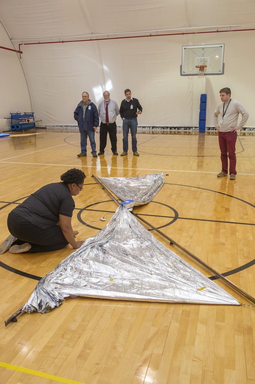
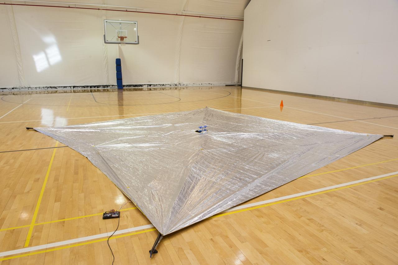
TIFFANY LOCKETT OVERSEES THE HALF SCALE (36 SQUARE METERS) ENGINEERING DEVELOPMENT UNIT (EDU) SOLAR SAIL DEPLOYMENT DEMONSTRATION IN PREPARATION FOR FULL SCALE EDU (86 SQUARE METERS) DEPLOYMENT IN APRIL, 2016
TIFFANY LOCKETT OVERSEES THE HALF SCALE (36 SQUARE METERS) ENGINEERING DEVELOPMENT UNIT (EDU) SOLAR SAIL DEPLOYMENT DEMONSTRATION IN PREPARATION FOR FULL SCALE EDU (86 SQUARE METERS) DEPLOYMENT IN APRIL, 2016
TIFFANY LOCKETT OVERSEES THE HALF SCALE (36 SQUARE METERS) ENGINEERING DEVELOPMENT UNIT (EDU) SOLAR SAIL DEPLOYMENT DEMONSTRATION IN PREPARATION FOR FULL SCALE EDU (86 SQUARE METERS) DEPLOYMENT IN APRIL, 2016
TIFFANY LOCKETT OVERSEES THE HALF SCALE (36 SQUARE METERS) ENGINEERING DEVELOPMENT UNIT (EDU) SOLAR SAIL DEPLOYMENT DEMONSTRATION IN PREPARATION FOR FULL SCALE EDU (86 SQUARE METERS) DEPLOYMENT IN APRIL, 2016
TIFFANY LOCKETT OVERSEES THE HALF SCALE (36 SQUARE METERS) ENGINEERING DEVELOPMENT UNIT (EDU) SOLAR SAIL DEPLOYMENT DEMONSTRATION IN PREPARATION FOR FULL SCALE EDU (86 SQUARE METERS) DEPLOYMENT IN APRIL, 2016
TIFFANY LOCKETT OVERSEES THE HALF SCALE (36 SQUARE METERS) ENGINEERING DEVELOPMENT UNIT (EDU) SOLAR SAIL DEPLOYMENT DEMONSTRATION IN PREPARATION FOR FULL SCALE EDU (86 SQUARE METERS) DEPLOYMENT IN APRIL, 2016
TIFFANY LOCKETT OVERSEES THE HALF SCALE (36 SQUARE METERS) ENGINEERING DEVELOPMENT UNIT (EDU) SOLAR SAIL DEPLOYMENT DEMONSTRATION IN PREPARATION FOR FULL SCALE EDU (86 SQUARE METERS) DEPLOYMENT IN APRIL, 2016
TIFFANY LOCKETT OVERSEES THE HALF SCALE (36 SQUARE METERS) ENGINEERING DEVELOPMENT UNIT (EDU) SOLAR SAIL DEPLOYMENT DEMONSTRATION IN PREPARATION FOR FULL SCALE EDU (86 SQUARE METERS) DEPLOYMENT IN APRIL, 2016
TIFFANY LOCKETT OVERSEES THE HALF SCALE (36 SQUARE METERS) ENGINEERING DEVELOPMENT UNIT (EDU) SOLAR SAIL DEPLOYMENT DEMONSTRATION IN PREPARATION FOR FULL SCALE EDU (86 SQUARE METERS) DEPLOYMENT IN APRIL, 2016
TIFFANY LOCKETT OVERSEES THE HALF SCALE (36 SQUARE METERS) ENGINEERING DEVELOPMENT UNIT (EDU) SOLAR SAIL DEPLOYMENT DEMONSTRATION IN PREPARATION FOR FULL SCALE EDU (86 SQUARE METERS) DEPLOYMENT IN APRIL, 2016
TIFFANY LOCKETT OVERSEES THE HALF SCALE (36 SQUARE METERS) ENGINEERING DEVELOPMENT UNIT (EDU) SOLAR SAIL DEPLOYMENT DEMONSTRATION IN PREPARATION FOR FULL SCALE EDU (86 SQUARE METERS) DEPLOYMENT IN APRIL, 2016
TIFFANY LOCKETT OVERSEES THE HALF SCALE (36 SQUARE METERS) ENGINEERING DEVELOPMENT UNIT (EDU) SOLAR SAIL DEPLOYMENT DEMONSTRATION IN PREPARATION FOR FULL SCALE EDU (86 SQUARE METERS) DEPLOYMENT IN APRIL, 2016
TIFFANY LOCKETT OVERSEES THE HALF SCALE (36 SQUARE METERS) ENGINEERING DEVELOPMENT UNIT (EDU) SOLAR SAIL DEPLOYMENT DEMONSTRATION IN PREPARATION FOR FULL SCALE EDU (86 SQUARE METERS) DEPLOYMENT IN APRIL, 2016
TIFFANY LOCKETT OVERSEES THE HALF SCALE (36 SQUARE METERS) ENGINEERING DEVELOPMENT UNIT (EDU) SOLAR SAIL DEPLOYMENT DEMONSTRATION IN PREPARATION FOR FULL SCALE EDU (86 SQUARE METERS) DEPLOYMENT IN APRIL, 2016
TIFFANY LOCKETT OVERSEES THE HALF SCALE (36 SQUARE METERS) ENGINEERING DEVELOPMENT UNIT (EDU) SOLAR SAIL DEPLOYMENT DEMONSTRATION IN PREPARATION FOR FULL SCALE EDU (86 SQUARE METERS) DEPLOYMENT IN APRIL, 2016
TIFFANY LOCKETT OVERSEES THE HALF SCALE (36 SQUARE METERS) ENGINEERING DEVELOPMENT UNIT (EDU) SOLAR SAIL DEPLOYMENT DEMONSTRATION IN PREPARATION FOR FULL SCALE EDU (86 SQUARE METERS) DEPLOYMENT IN APRIL, 2016
TIFFANY LOCKETT OVERSEES THE HALF SCALE (36 SQUARE METERS) ENGINEERING DEVELOPMENT UNIT (EDU) SOLAR SAIL DEPLOYMENT DEMONSTRATION IN PREPARATION FOR FULL SCALE EDU (86 SQUARE METERS) DEPLOYMENT IN APRIL, 2016
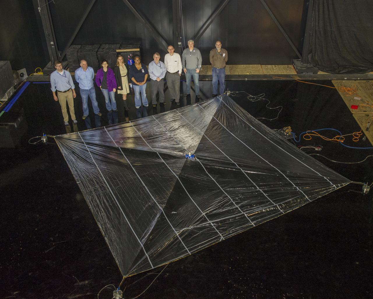
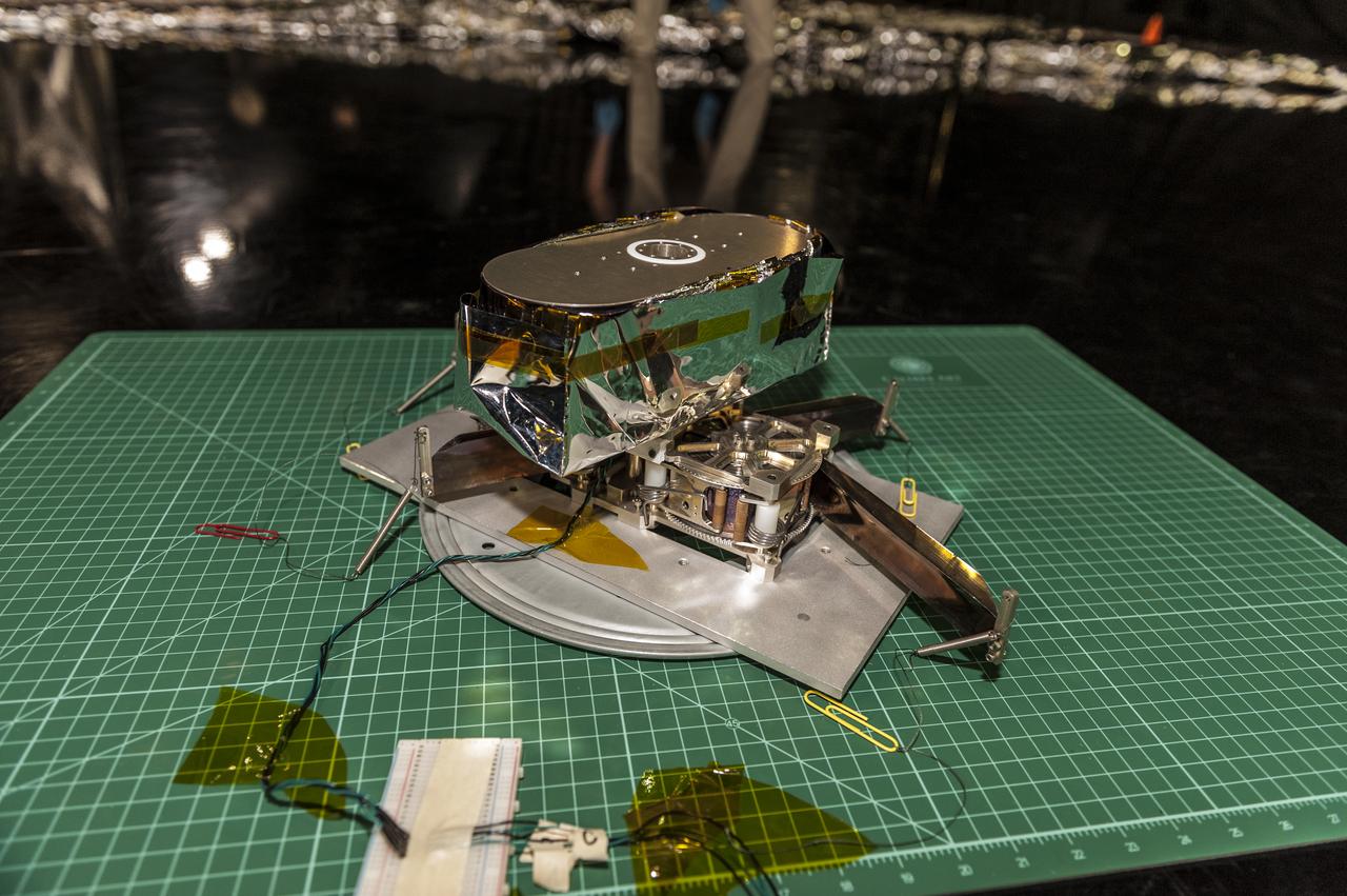
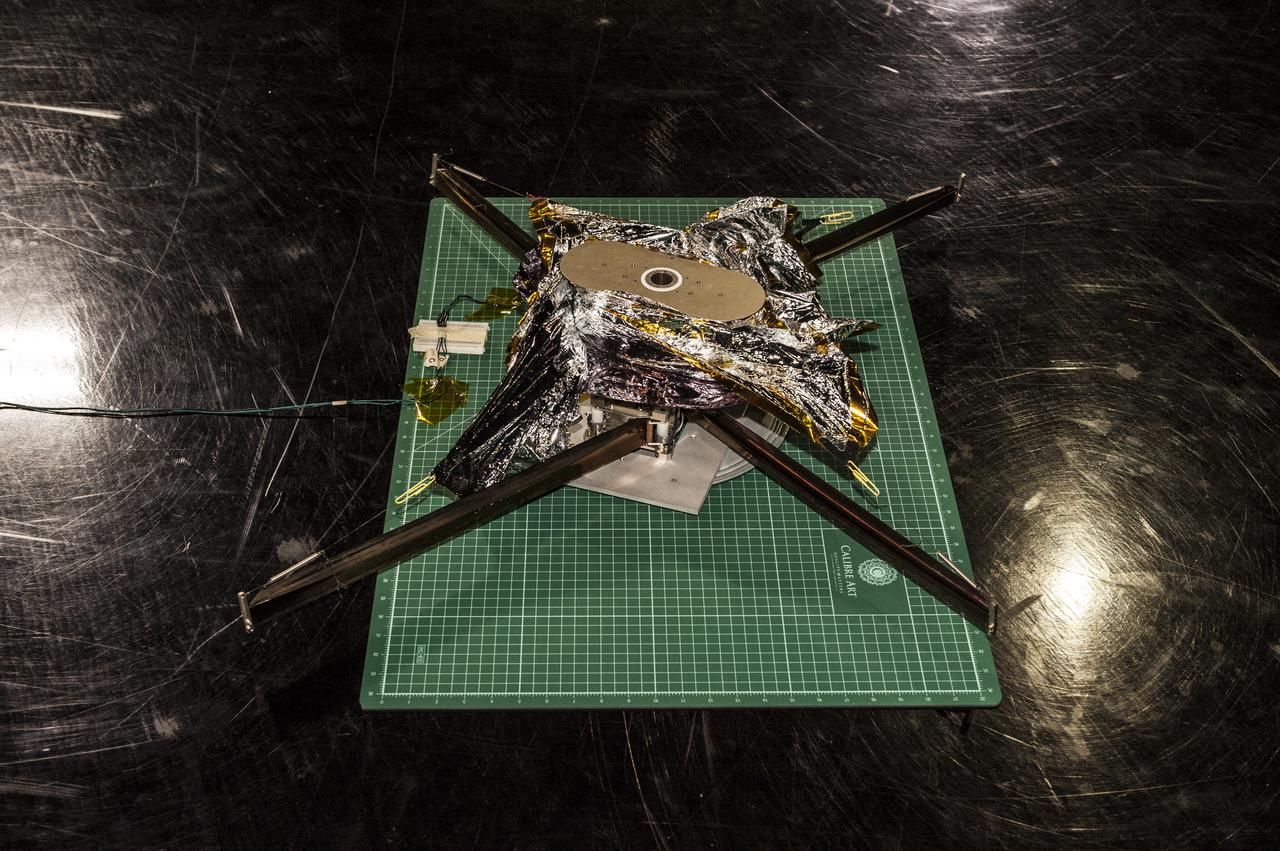
NEA (Near Earth Asteroid) Scout Solar Sail, deployed, with team members: Alex Sobey, Andy Heaton, Olive Stohlmann, Leslie McNutt, Tiffany Russell Lockett, Roy Young, Les Johnson, Kevin Sykes, Tom Bryan
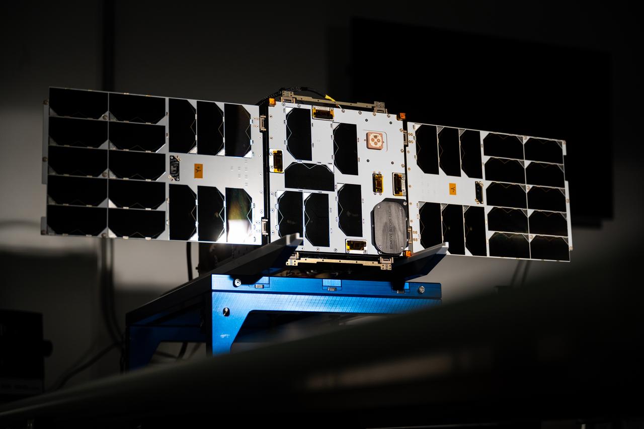
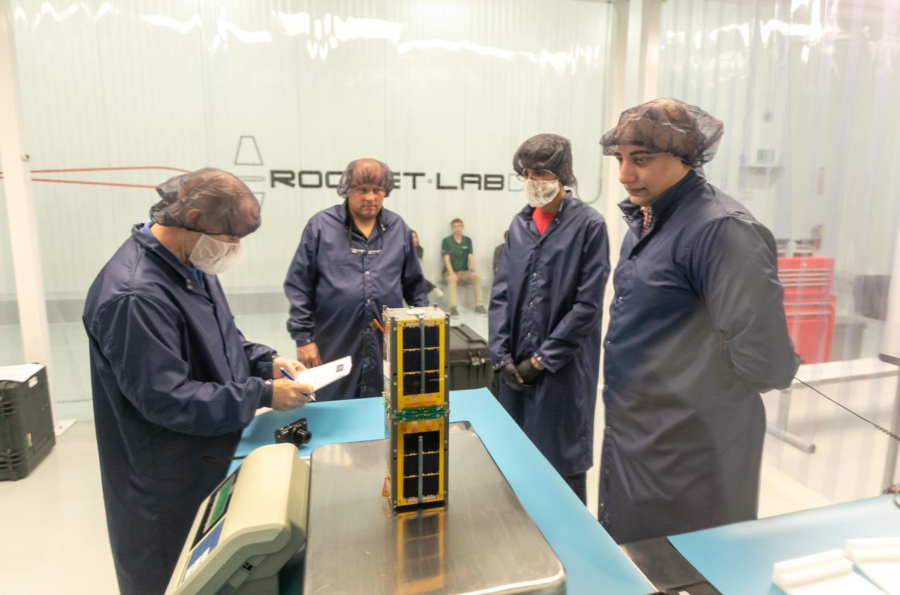
Overview of the solar panels test of the Advanced Composite Solar Sail System (ACS3) spacecraft in the Ames Integration Facility in N213 room 104.
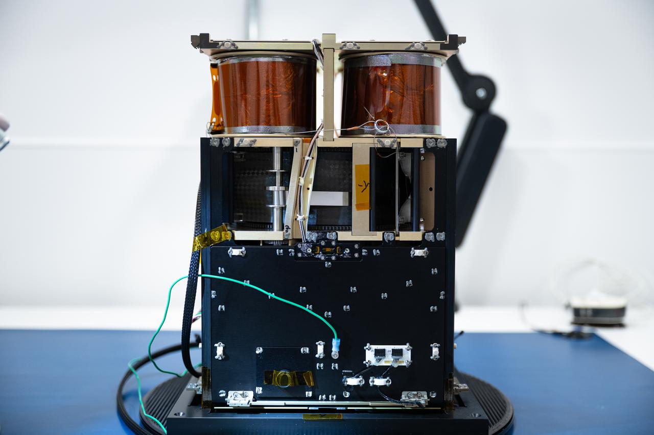
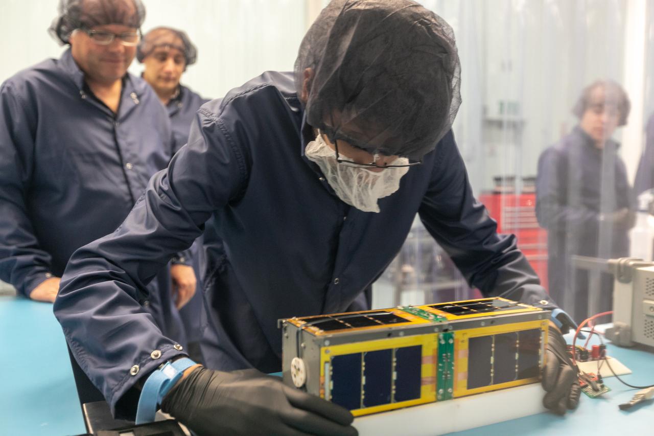
Overview of the -Y axis of the Advanced Composite Solar Sail System (ACS3) spacecraft before the installation of the solar panels in the Ames Integration Facility in N213 room 104.
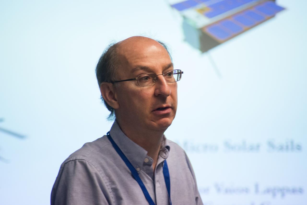
LES JOHNSON INTRODUCES PROFESSOR VARIOS LAPP, UNIVERSITY OF SURREY, UK, PRIME INVESTIGATOR OF SOLAR SAIL TECHNOLOGY
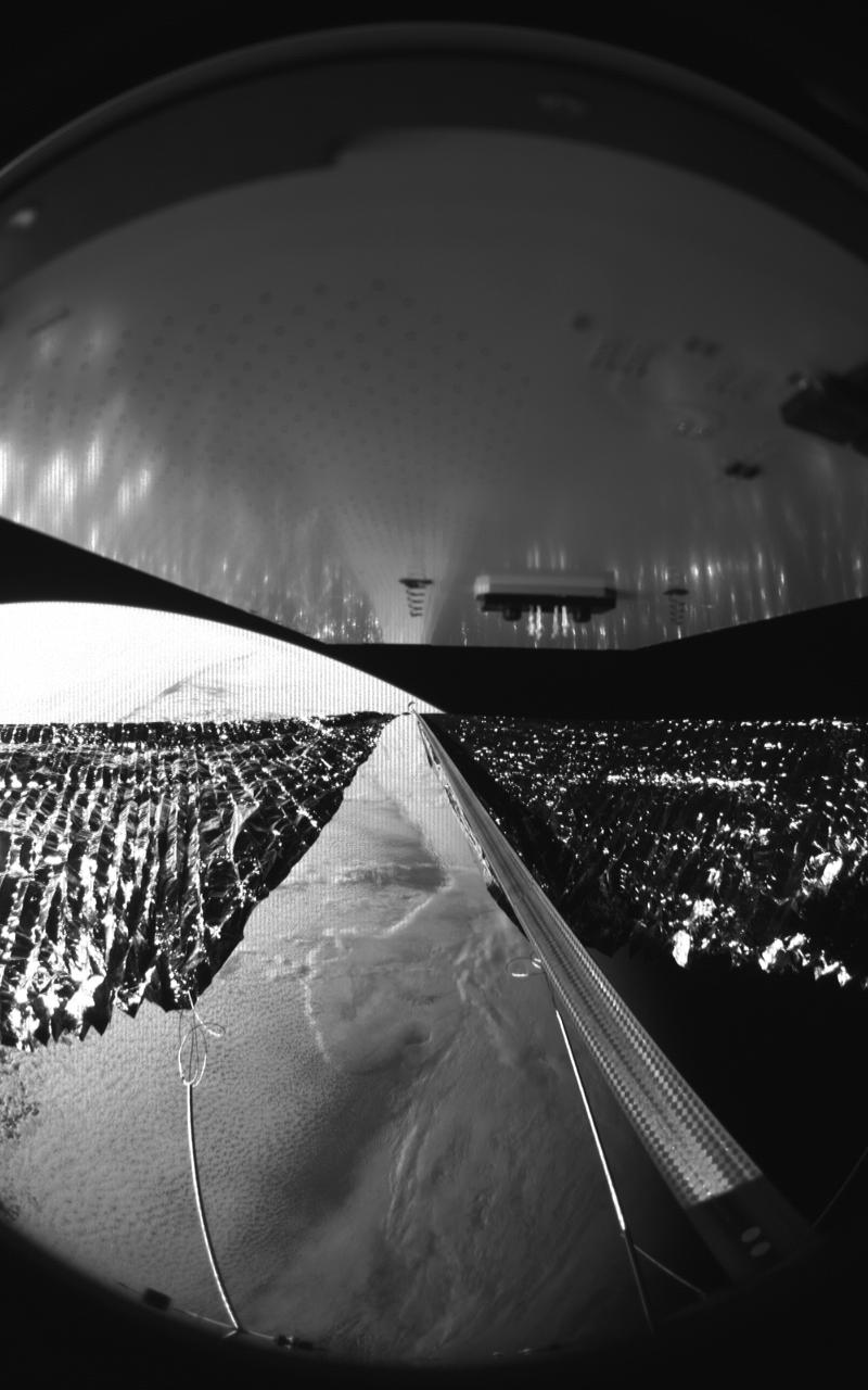
Four cameras aboard the Advanced Composite Solar Sail System spacecraft show the four reflective sail quadrants supported by composite booms. The booms are mounted at right angles and the spacecraft’s solar panel is rectangular, but lines appear distorted because of the wide-angle camera field of view. View from a black-and-white wide-angle camera aboard the Advanced Composite Solar Sail System taken during sail unfurling in low Earth orbit. The spacecraft has four such cameras, centrally located aboard the spacecraft. Here, reflective sail quadrants supported by composite booms are seen when the booms are partially extended and the sail quadrants are not taut. At the top of the photo is the back surface of one of the spacecraft’s solar panels. On the lower left Earth is seen below.
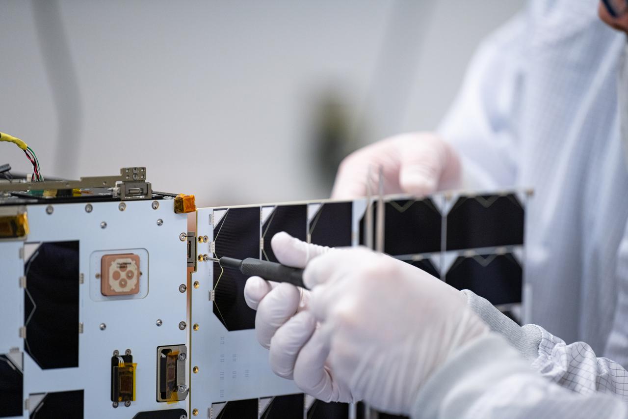
Craig Turczynski, and Mario Perez install the solar panels on the +Y and -Y axis of Advanced Composite Solar Sail System (ACS3) spacecraft in the Ames Integration Facility in N213 room 104.
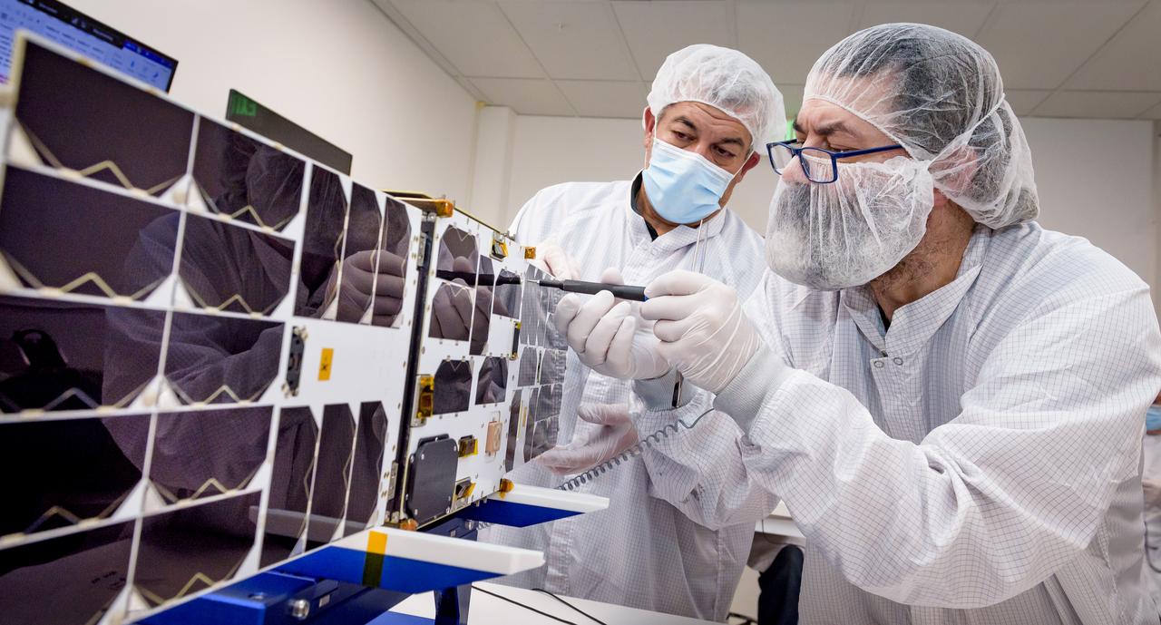
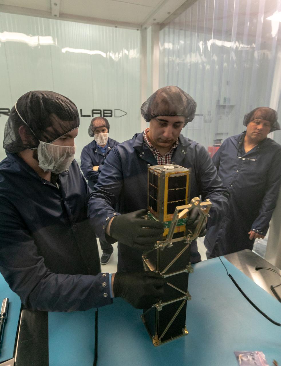
Mario Perez, back, holds the deployable solar panel as Craig Turczynski, left, secures it to the Advanced Composite Solar Sail System (ACS3) spacecraft in the Ames Integration Facility located in N213 room 104.
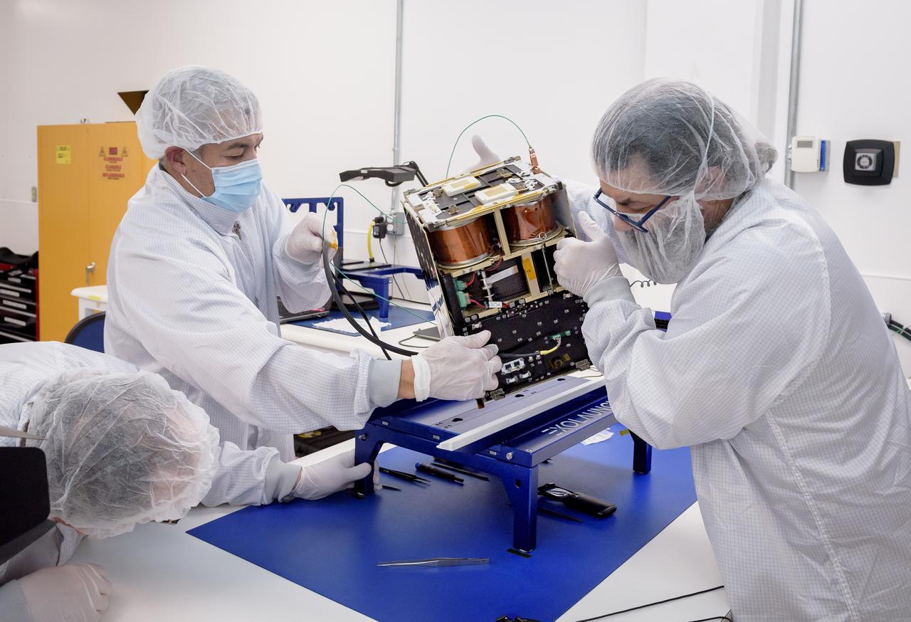
Left to right: Keats Wilkie, Mario Perez, and Craig Turczynski rotate the Advanced Composite Solar Sail System (ACS3) spacecraft on the workbench of the Ames Integration Facility located in N213 room 104.
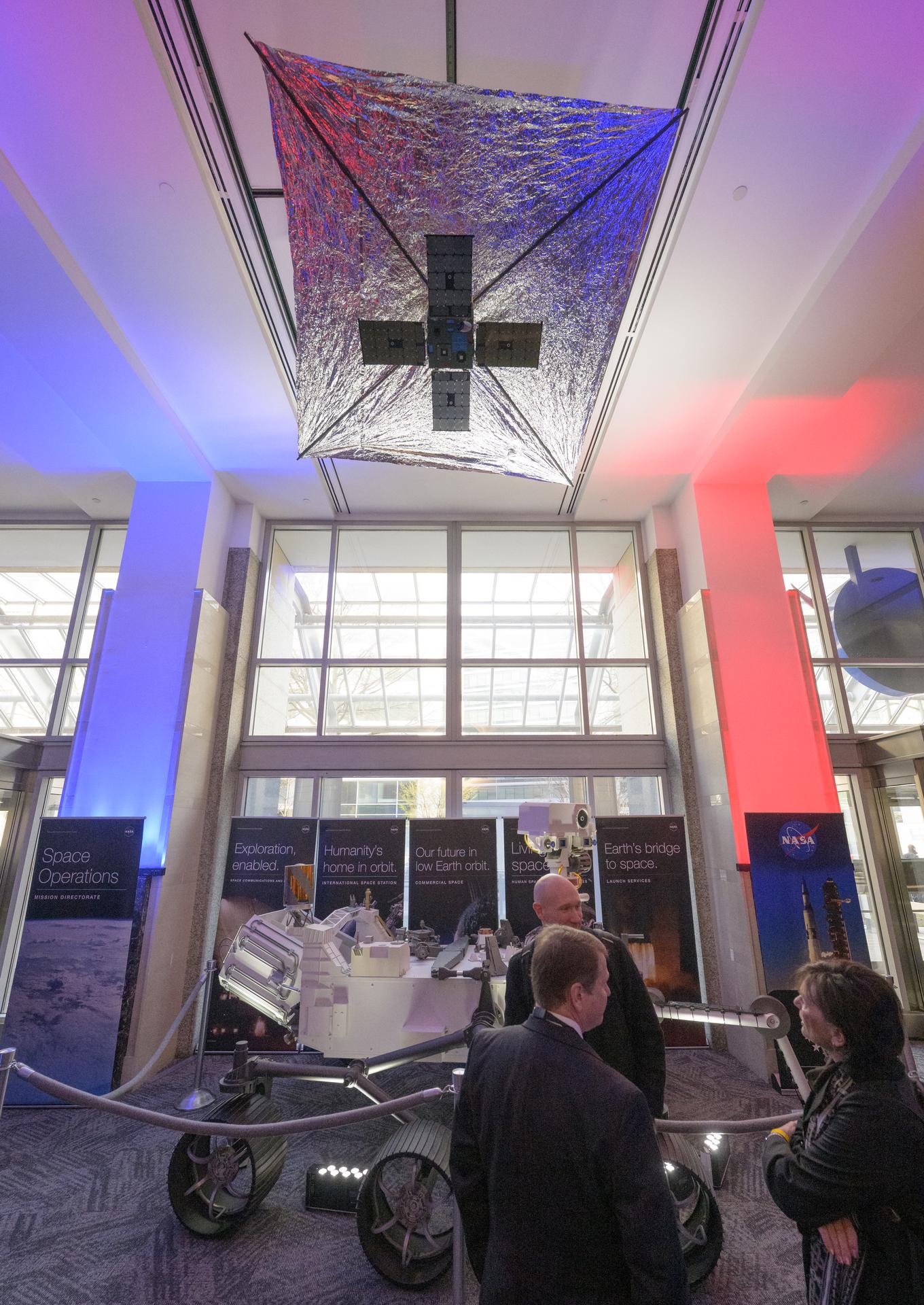
A model of the Advanced Composite Solar Sail System (ACS3) is seen in the NASA Headquarters lobby during a 2-day event where NASA outlined how the agency is executing President Donald J. Trump’s National Space Policy and accelerating preparations for America’s return to the surface of the Moon by 2028, Wednesday, March 25, 2026, at the Mary W. Jackson NASA Headquarters building in Washington. During the event NASA leadership provided updates on mission priorities, including sending the first astronauts to the lunar surface in more than 50 years, establishing the initial elements of a permanent lunar base, getting America underway in space on nuclear propulsion, and other objectives. Photo Credit: (NASA/Bill Ingalls)
BTK Able 20 meter Solar Sail being deployed with all four sections for the first time. Solar sails are intended for deep space science missions.
BTK Able 20 meter Solar Sail being deployed with all four sections for the first time. Solar sails are intended for deep space science missions.
BTK Able 20 meter Solar Sail being deployed with all four sections for the first time. Solar sails are intended for deep space science missions.
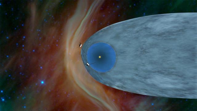
This artist concept shows the general locations of NASA two Voyager spacecraft. Voyager 1 top has sailed beyond our solar bubble into interstellar space. Voyager 2 bottom is still exploring the outer layer of the solar bubble.
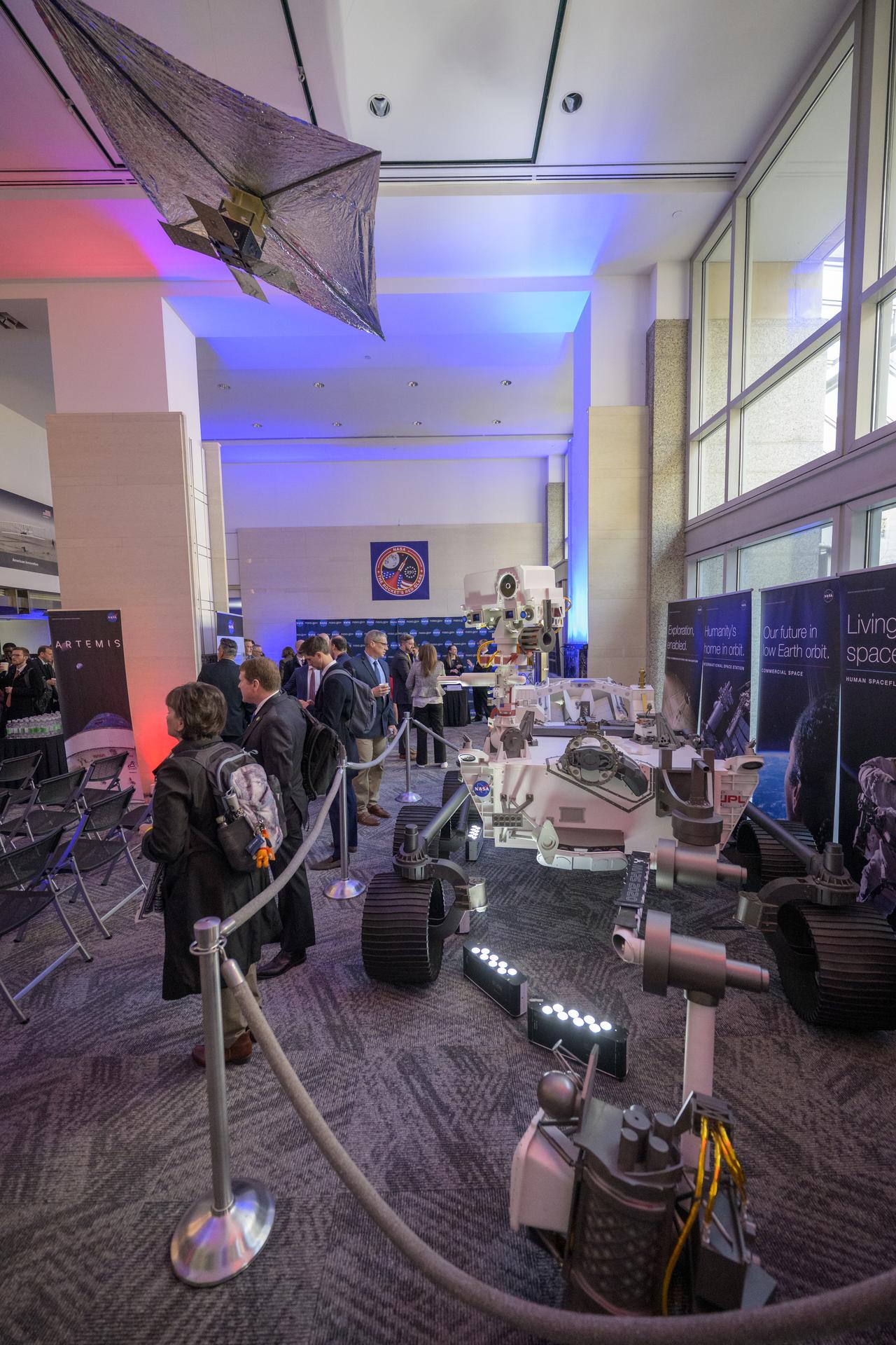
NASA Headquarters lobby is seen with models of the Mars 2020 Perseverance Rover, and Advanced Composite Solar Sail System (ACS3) on display ahead of an event where NASA outlined how the agency is executing President Donald J. Trump’s National Space Policy and accelerating preparations for America’s return to the surface of the Moon by 2028, Tuesday, March 24, 2026, at the Mary W. Jackson NASA Headquarters building in Washington. During the event NASA leadership provided updates on mission priorities, including sending the first astronauts to the lunar surface in more than 50 years, establishing the initial elements of a permanent lunar base, getting America underway in space on nuclear propulsion, and other objectives. Photo Credit: (NASA/Bill Ingalls)
NASA Headquarters lobby is seen with models of the Mars 2020 Perseverance Rover, and Advanced Composite Solar Sail System (ACS3) on display ahead of an event where NASA outlined how the agency is executing President Donald J. Trump’s National Space Policy and accelerating preparations for America’s return to the surface of the Moon by 2028, Tuesday, March 24, 2026, at the Mary W. Jackson NASA Headquarters building in Washington. During the event NASA leadership provided updates on mission priorities, including sending the first astronauts to the lunar surface in more than 50 years, establishing the initial elements of a permanent lunar base, getting America underway in space on nuclear propulsion, and other objectives. Photo Credit: (NASA/Bill Ingalls)
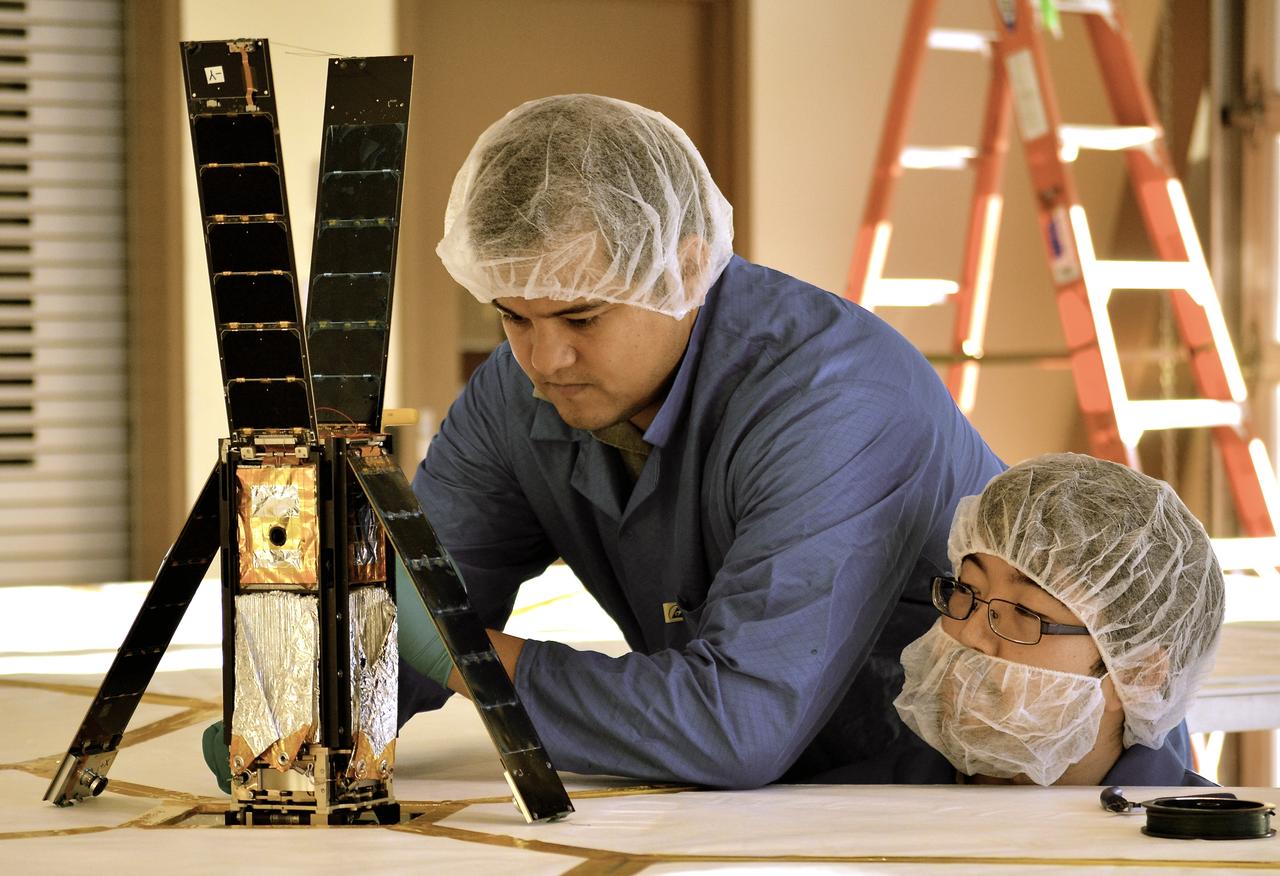
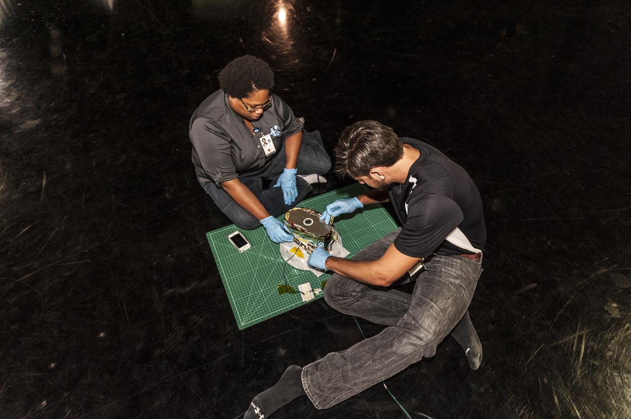
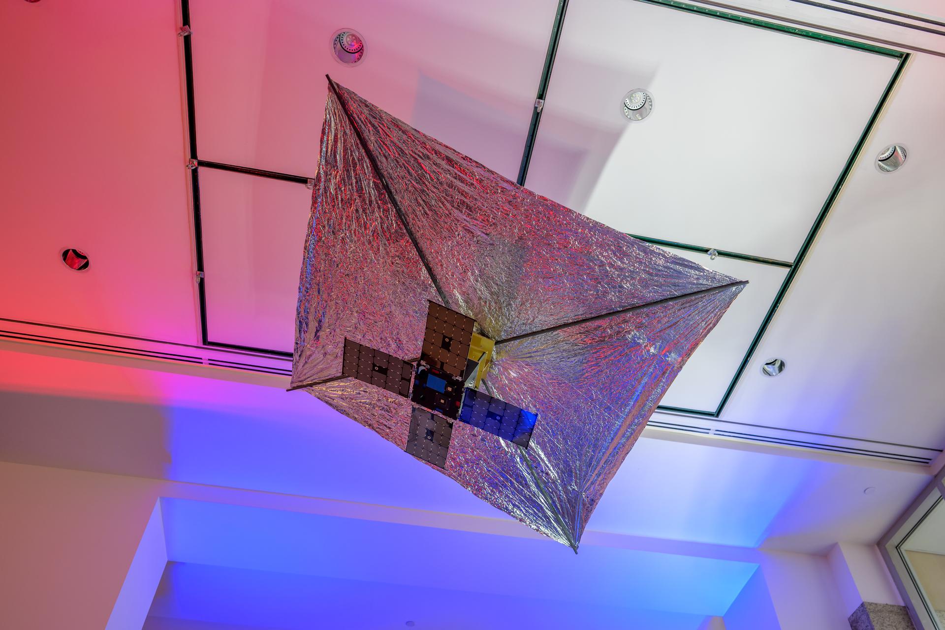
Students Alex Diaz and Riki Munakata of California Polytechnic State University testing the LightSail CubeSat. LightSail is a citizen-funded technology demonstration mission sponsored by the Planetary Society using solar propulsion for CubeSats. The spacecraft is designed to “sail” on the energy of solar photons striking the thin, reflective sail material. The first LightSail mission is designed to test the spacecraft’s critical systems, including the sequence to autonomously deploy a Mylar solar sail with an area of 32 square meters (344 square feet). The Planetary Society is planning a second, full solar sailing demonstration flight for 2016. Light is made of packets of energy called photons. While photons have no mass, they have energy and momentum. Solar sails use this momentum as a method of propulsion, creating flight by light. LightSail’s solar sail is packaged into a three-unit CubeSat about the size of a loaf of bread. Launched by NASA’s CubeSat Launch Initiative on the ELaNa XI mission as an auxiliary payload aboard the U.S. Air Force X-37B space plane mission on May 20, 2015.
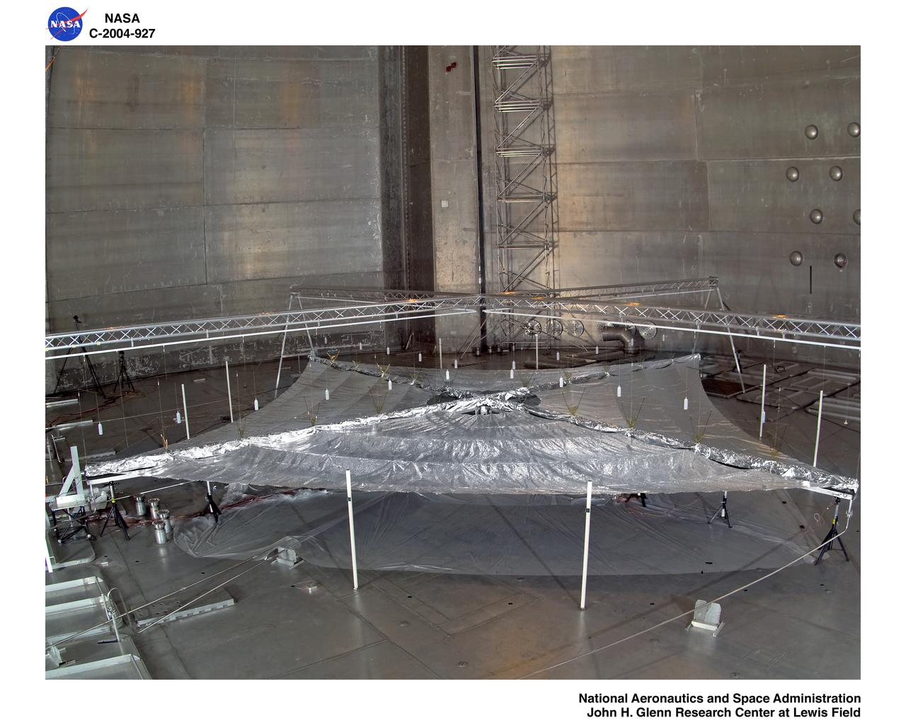
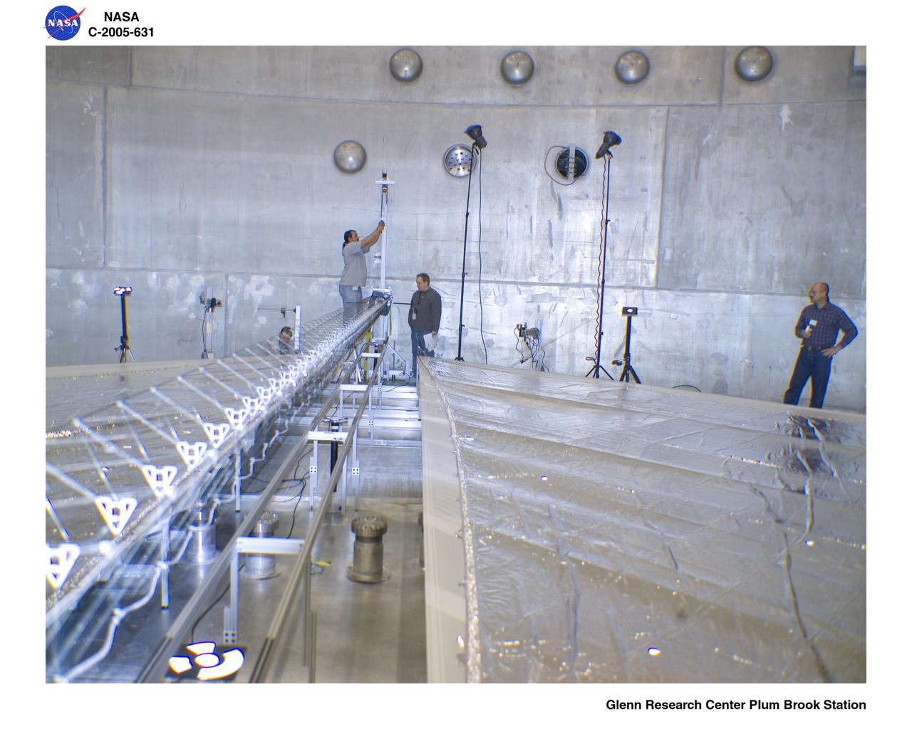
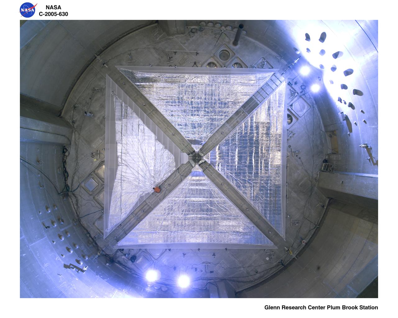
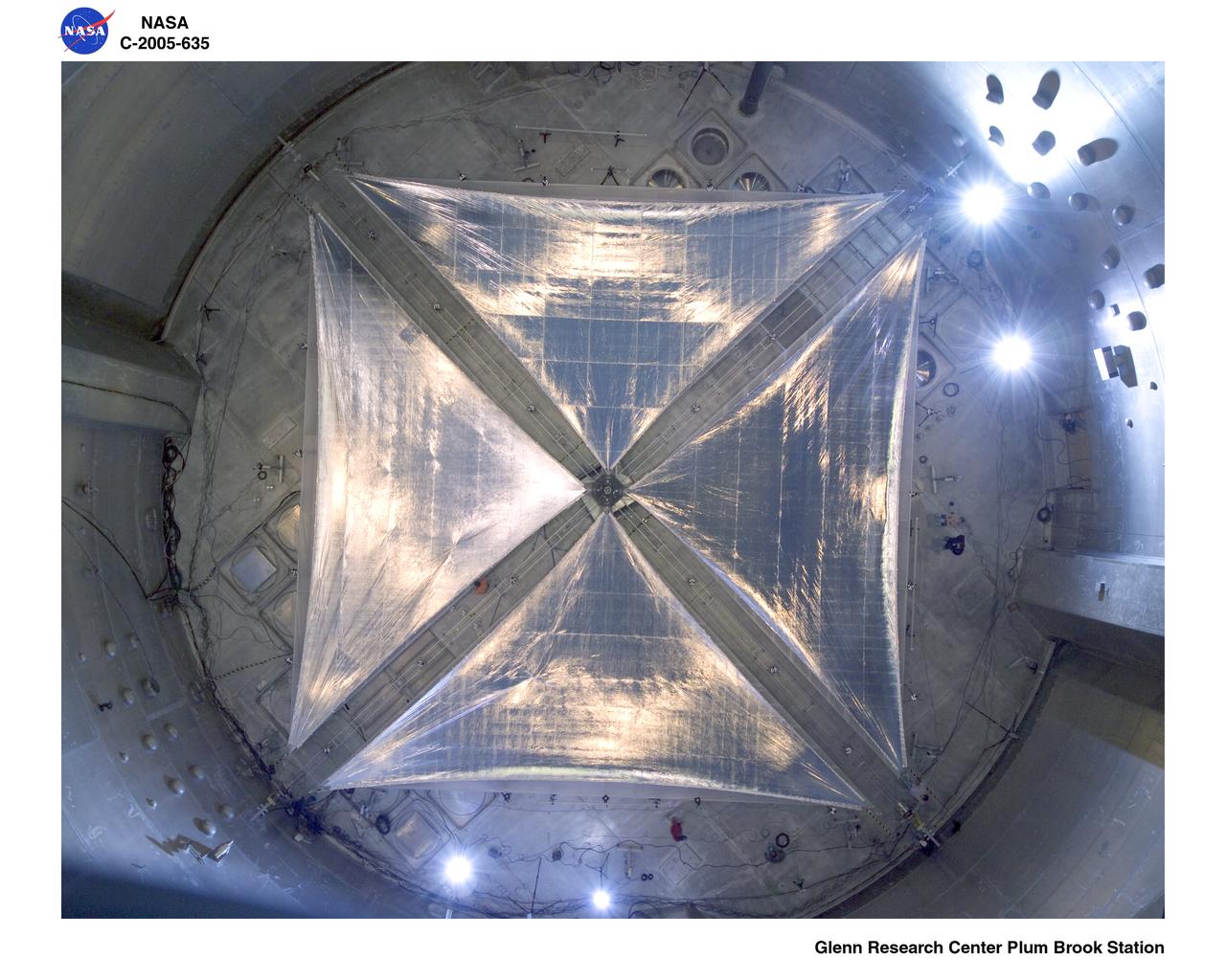
Solar Sail Testing at the Plum Brook Space Power Facility (SPF)
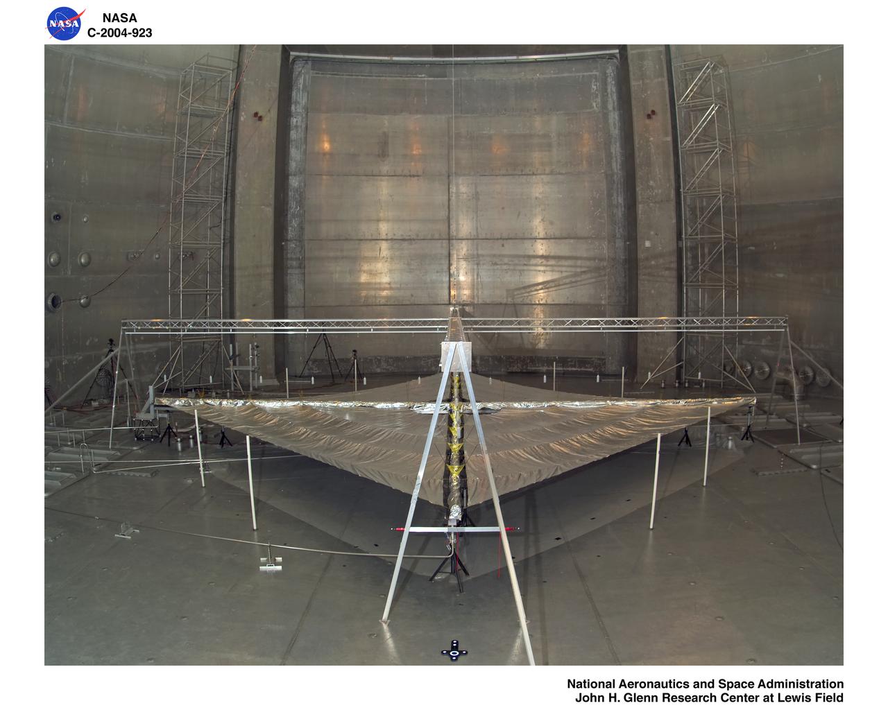
Solar Sail Testing at the Plum Brook Space Power Facility (SPF)
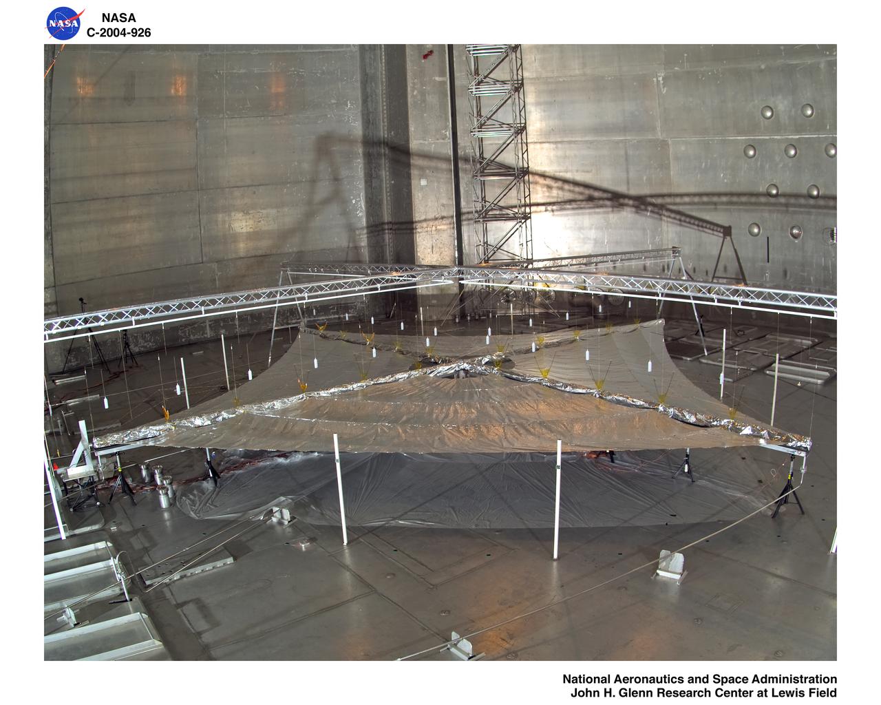
Solar Sail Testing at the Plum Brook Space Power Facility (SPF)
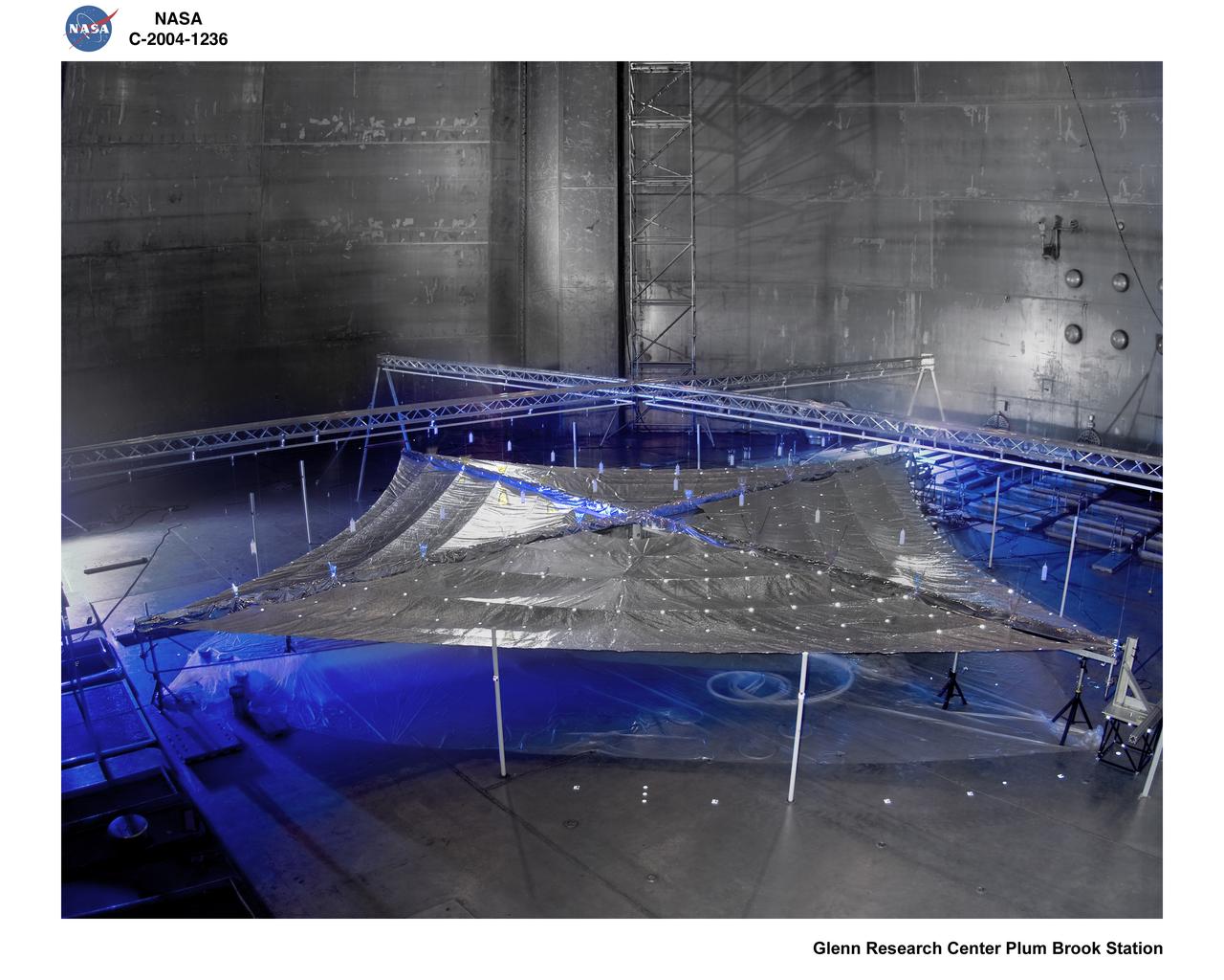
Solar Sail Testing at the NASA Plum Brook Space Power Facility (SPF)
CubeSail is a nano-scale flight experiment to demonstrate deployment and control of a single 250-meter (20 m2) solar sail blade as a low-cost risk reduction precursor of the exciting advanced interplanetary UltraSail concept having four 5-kilometer blades (with approximately 100,000 m2 of sail area). CubeSail was built by the University of Illinois at Urbana-Champaign and CU Aerospace, the same team that designed the I-Sail and UltraSail concepts funded by NASA’s SBIR program. CubeSail represents an affordable stepping-stone towards the future development of the UltraSail solar sail concept that would enable very high-energy inner heliosphere and interstellar scientific missions. In addition, near-earth missions such as Heliostorm for early warning of solar storms will provide more warning margin as the solar sail performance is increased with UltraSail technology. Spacecraft design studies show that for sail areal densities below 5 gm/m2, as proposed with UltraSail, that spacecraft payloads can be significantly increased to 50-60% because of the elimination of the propellant, without sacrificing flight time. Furthermore, higher payload fractions will result in dramatically lower total spacecraft mass and consequently much lower launch cost, enabling more missions for the research dollar.
CubeSail is a nano-scale flight experiment to demonstrate deployment and control of a single 250-meter (20 m2) solar sail blade as a low-cost risk reduction precursor of the exciting advanced interplanetary UltraSail concept having four 5-kilometer blades (with approximately 100,000 m2 of sail area). CubeSail was built by the University of Illinois at Urbana-Champaign and CU Aerospace, the same team that designed the I-Sail and UltraSail concepts funded by NASA’s SBIR program. CubeSail represents an affordable stepping-stone towards the future development of the UltraSail solar sail concept that would enable very high-energy inner heliosphere and interstellar scientific missions. In addition, near-earth missions such as Heliostorm for early warning of solar storms will provide more warning margin as the solar sail performance is increased with UltraSail technology. Spacecraft design studies show that for sail areal densities below 5 gm/m2, as proposed with UltraSail, that spacecraft payloads can be significantly increased to 50-60% because of the elimination of the propellant, without sacrificing flight time. Furthermore, higher payload fractions will result in dramatically lower total spacecraft mass and consequently much lower launch cost, enabling more missions for the research dollar.
CubeSail is a nano-scale flight experiment to demonstrate deployment and control of a single 250-meter (20 m2) solar sail blade as a low-cost risk reduction precursor of the exciting advanced interplanetary UltraSail concept having four 5-kilometer blades (with approximately 100,000 m2 of sail area). CubeSail was built by the University of Illinois at Urbana-Champaign and CU Aerospace, the same team that designed the I-Sail and UltraSail concepts funded by NASA’s SBIR program. CubeSail represents an affordable stepping-stone towards the future development of the UltraSail solar sail concept that would enable very high-energy inner heliosphere and interstellar scientific missions. In addition, near-earth missions such as Heliostorm for early warning of solar storms will provide more warning margin as the solar sail performance is increased with UltraSail technology. Spacecraft design studies show that for sail areal densities below 5 gm/m2, as proposed with UltraSail, that spacecraft payloads can be significantly increased to 50-60% because of the elimination of the propellant, without sacrificing flight time. Furthermore, higher payload fractions will result in dramatically lower total spacecraft mass and consequently much lower launch cost, enabling more missions for the research dollar.
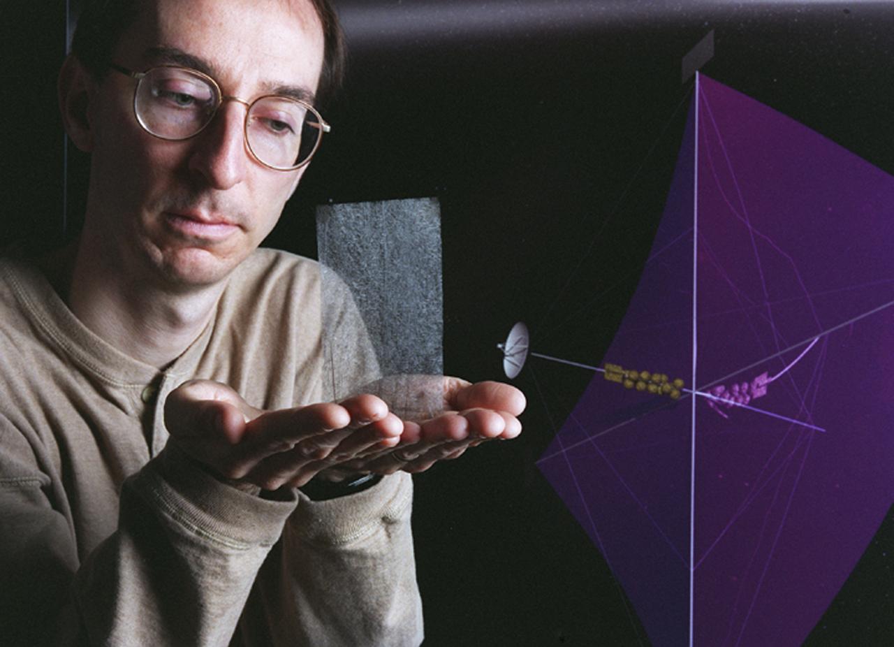
Engineers at Marshall Space Flight Center's (MSFC) Interstellar Propulsion Research department are proposing different solutions to combustion propellants for future space travel. One alternative being tested is the solar sail. The idea is, once deployed, the sail will allow solar winds to propel a spacecraft away from Earth and towards its destination. This would allow a spacecraft to travel indefinitely without the need to refuel during its ong journey. Thin reflective sails could be propelled through space by sunlight, microwave beams, or laser beams, just as the wind pushes sailboats on Earth. The sail will be the largest spacecraft ever built, sparning 440 yards, twice the diameter of the Louisiana Super Dome. Construction materials are being tested in a simulated space environment, where they are exposed to harsh conditions to test their performance and durability in extremely hot and cold temperatures. A leading candidate for the construction material is a carbon fiber material whose density is less than 1/10 ounce per square yard, the equivalent of flattening one raisin to the point that it covers a square yard. In space, the material would unfurl like a fan when it is deployed from an expendable rocket. This photo shows Les Johnson, manager of MSFC's Interstellar Propulsion Research Center holding the rigid, lightweight carbon fiber. An artist's concept of the sail is on the right. Mankind's first venture outside of our solar system is proposed for launch in a 2010 timeframe. An interstellar probe, powered by the fastest spacecraft ever flown, will zoom toward the stars at 58 miles per second. It will cover the distance from New York to Los Angeles in less than a minute and will travel over 23 billion miles beyond the edge of the solar system.
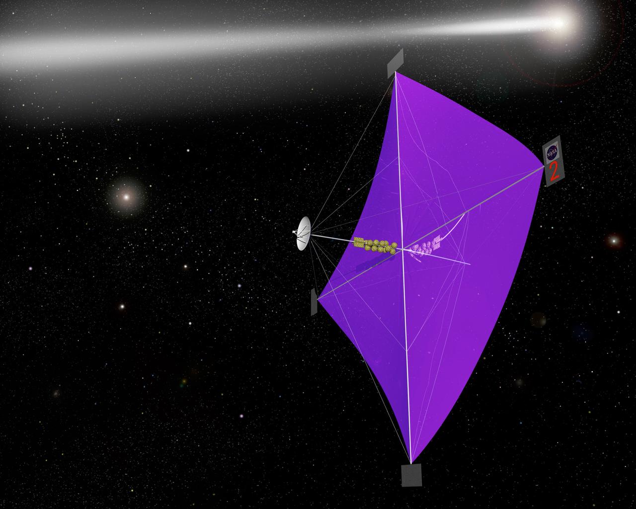
Engineers at Marshall Space Flight Center's Interstellar Propulsion Research department are proposing different solutions to combustion propellants for future space travel. Pictured here is one alternative, the solar sail, depicted through an artist's concept. The idea is, once deployed, the sail will allow solar winds to propel a spacecraft away from Earth and towards its destination. This would allow a spacecraft to travel indefinitely without the need to refuel during its prolong journey. Thin reflective sails could be propelled through space by sunlight, microwave beams, or laser beams, just as the wind pushes sailboats on Earth. The sail will be the largest spacecraft ever built, sparning 440 yards, twice the diameter of the Louisiana Super Dome. Construction materials are being tested in a simulated space environment, where they are exposed to harsh conditions to test their performance and durability in extremely hot and cold temperatures. A leading candidate for the construction material is a carbon fiber material whose density is less than 1/10 ounce per square yard, the equivalent of flattening one raisin to the point that it covers a square yard. In space, the material would unfurl like a fan when it is deployed from an expendable rocket. Mankind's first venture outside of our solar system is proposed for launch in a 2010 timeframe. An interstellar probe, powered by the fastest spacecraft ever flown, will zoom toward the stars at 58 miles per second. It will cover the distance from New York to Los Angeles in less than a minute and will travel over 23 billion miles beyond the edge of the solar system.
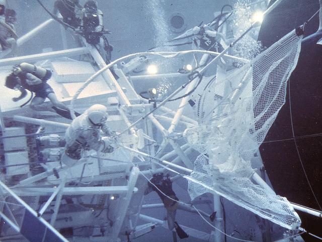
After its launch on May 14, 1973, it was immediately known that there were some major problems with Skylab. The large, delicate, meteoroid shield on the outside of the workshop was ripped off by the vibration of the launch. Its tearing off caused serious damage to the two wings of solar cells that were to supply most of the electric power to the workshop. Once in orbit, the news worsened. The loss of the big shade exposed the metal skin of the workshop to the sun. Internal temperatures soared to 126 degrees F. This heat not only threatened its habitation by astronauts, but if prolonged, would cause serious damage to instruments and film. After twice delaying the launch of the first astronaut crew, engineers worked frantically to develop solutions to these problems and salvage the Skylab. After designing a protective solar sail to cover the workshop, crews needed to practice using the specially designed tools and materials to facilitate the repair procedure. Marshall Space Flight Center's Neutral Buoyancy Simulator (NBS), was used to practice these maneuvers. Pictured here are the astronauts in the NBS deploying the protecticve solar sail. On may 25, 1973, an Apollo command and service module was launched and later docked with Skylab. The next day, astronauts Conrad and Kerwin were able to complete the needed repairs to Skylab, salvaging the entire program.
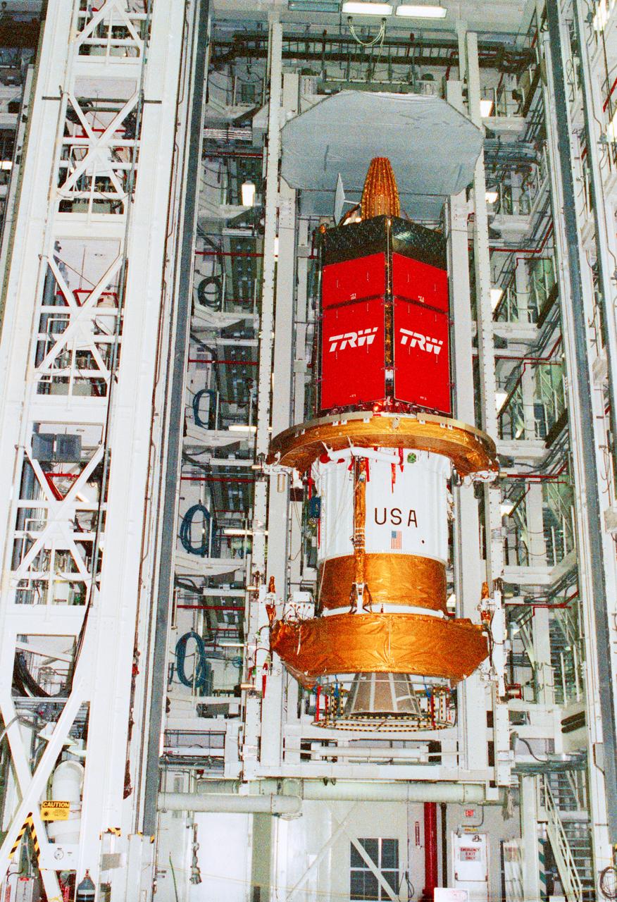
STS-43 Tracking and Data Relay Satellite E (TDRS-E) undergoes preflight processing in the Kennedy Space Center's (KSC's) Vertical Processing Facility (VPF) before being loaded into a payload canister for transfer to the launch pad and eventually into Atlantis', Orbiter Vehicle (OV) 104's, payload bay (PLB). This side of the TDRS-E will rest at the bottom of the PLB therefore the airborne support equipment (ASE) forward frame keel pin (at center of spacecraft) and the umbilical boom running between the two ASE frames are visible. The solar array panels are covered with protective TRW shields. Above the shields the stowed antenna and solar sail are visible. The inertial upper stage (IUS) booster is the white portion of the spacecraft and rests in the ASE forward frame and ASE aft frame tilt actuator (AFTA) frame (at the bottom of the IUS). The IUS booster nozzle extends beyond the AFTA frame. View provided by KSC with alternate number KSC-91PC-1079.
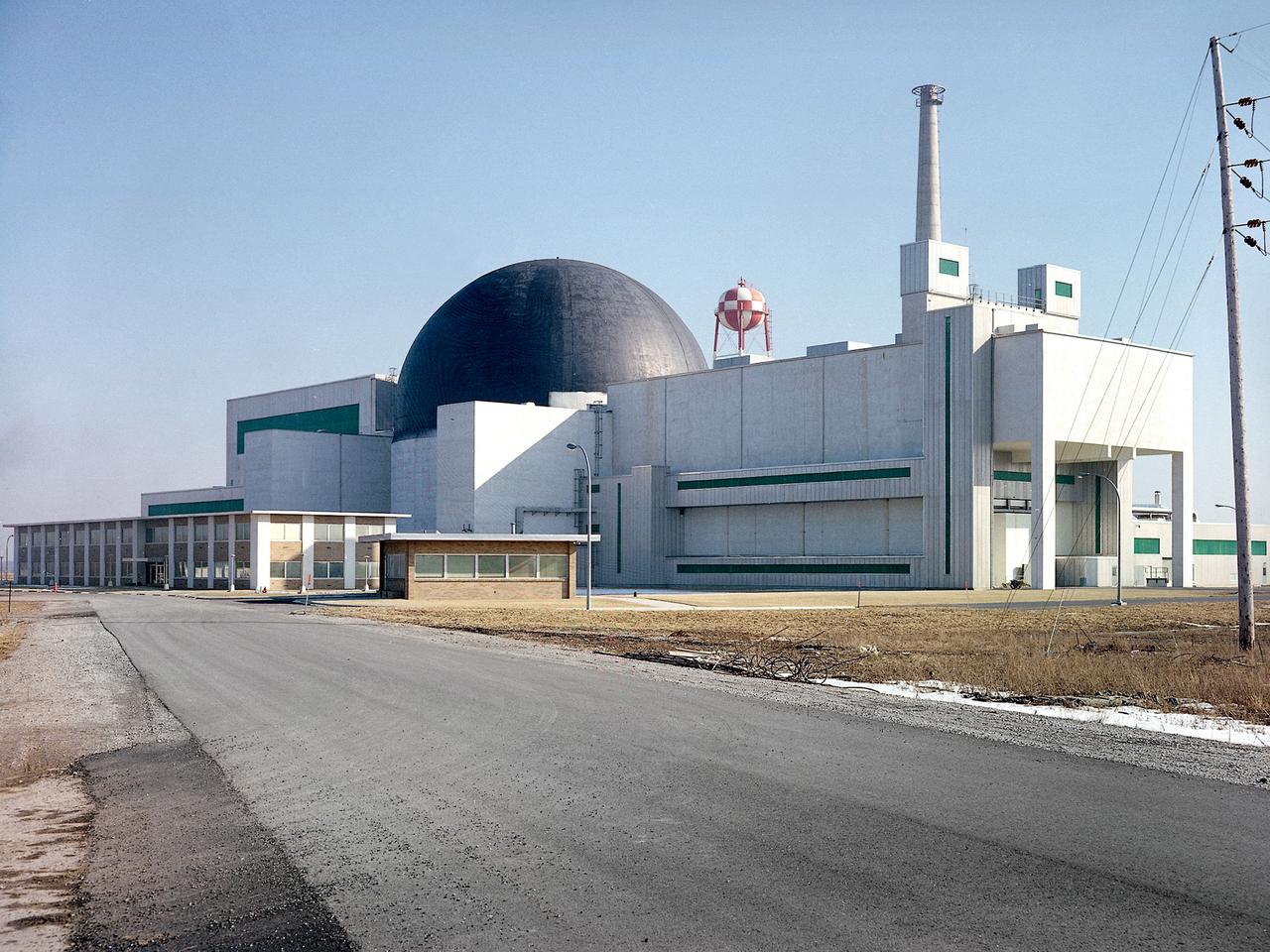
Exterior view of the Space Power Facility at the National Aeronautics and Space Administration’s (NASA) Plum Brook Station in Sandusky, Ohio. The $28.4-million facility, which began operations in 1969, is the largest high vacuum chamber ever built. The chamber is 100 feet in diameter and 120 feet high. It produces a vacuum deep enough to simulate the conditions at 300 miles altitude. The facility can sustain a high vacuum; simulate solar radiation via a 4-megawatt quartz heat lamp array, solar spectrum by a 400-kilowatt arc lamp, and cold environments. The Space Power Facility was originally designed to test nuclear power sources for spacecraft during long durations in a space atmosphere, but it was never used for that purpose. The facility’s first test in 1970 involved a 15 to 20-kilowatt Brayton Cycle Power System for space applications. Three different methods of simulating solar heat were employed during the Brayton tests. The facility was also used for jettison tests of the Centaur Standard Shroud. The shroud was designed for the new Titan-Centaur rocket that was scheduled to launch the Viking spacecraft to Mars. The new shroud was tested under conditions that simulated the time from launch to the separation of the stages. Test programs at the facility include high-energy experiments, shroud separation tests, Mars Lander system tests, deployable Solar Sail tests and International Space Station hardware tests.
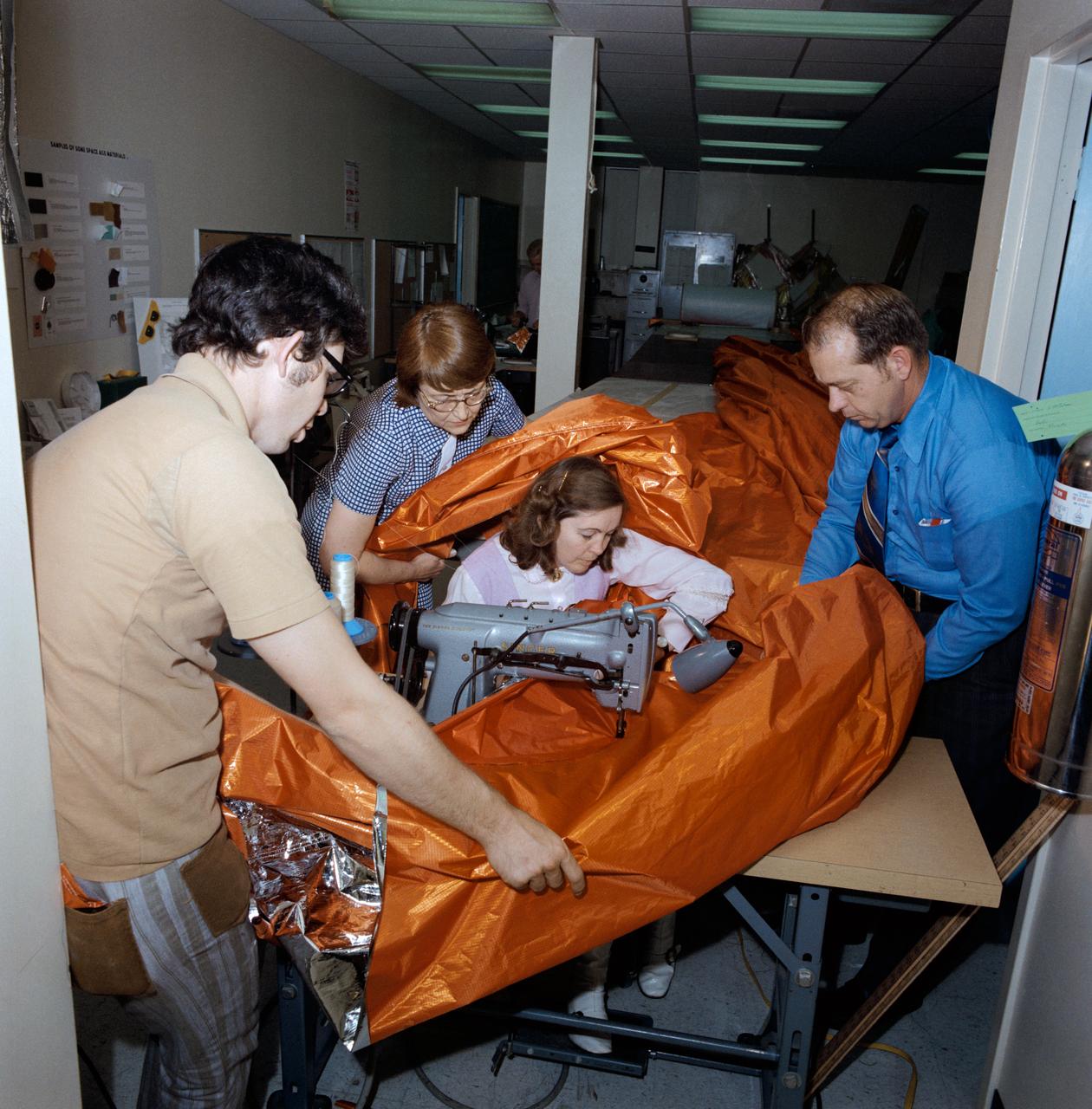
S73-26047 (18 May 1973) --- A sail-like sunshade for possible use as a sunscreen for the Skylab orbital workshop (OWS) is shown being fabricated in the GE Building across the street from the Johnson Space Center. Three persons assist the seamstress feed the material through the sewing machine. The three-layered shade will be composed of a top layer of aluminum Mylar, a middle layer of laminated nylon rip stop, and a bottom layer of thin nylon. Working on the sunshade, from left to right, are Dale Gentry, Elizabeth Gauldin, Alyene Baker and James H. Barnett Jr. Mrs. Baker, a GE employee, operates the double-needle sewing machine. Barnett is head of the Crew Equipment Development Section of JSC's Crew Systems Division. Mrs. Gauldin is also with the Crew Systems Division. Gentry works for GE. The work shown here is part of the crash program underway to prepare a protection device for Skylab to replace the original shield which was lost when the unmanned Skylab 1 launch took place on May 14, 1973. The improvised solar shield selected to be used will be carried to Earth orbit by the Skylab 2 crew, who will deploy it to shade part of the OWS from the hot rays of the sun. Loss of the original shield, as expected, has caused an overheating problem on the OWS. Photo credit: NASA
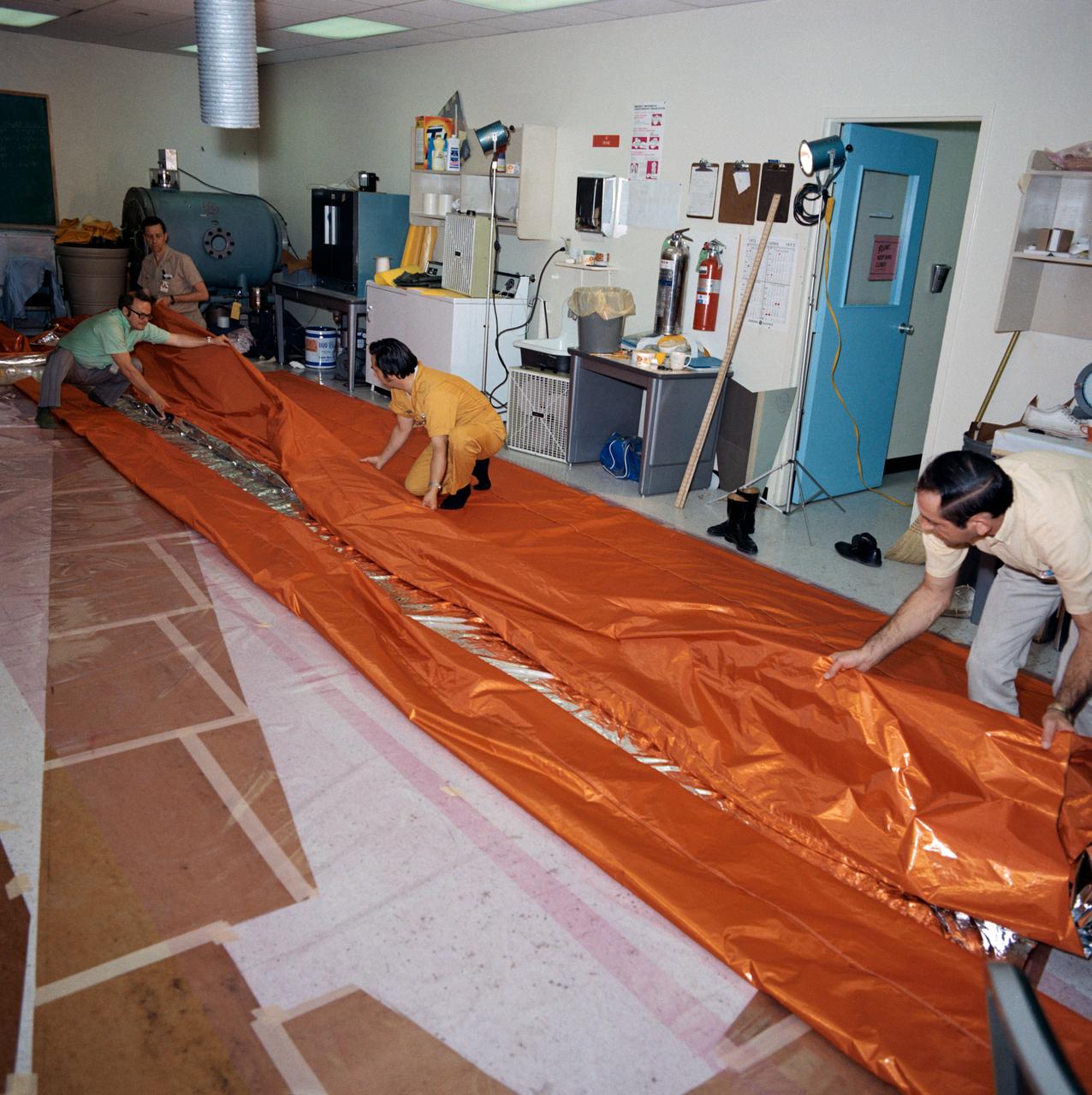
S73-26046 (18 May 1973) --- Workmen in the GE Building across the street from the Johnson Space Center fold a sail-like sunshade being fabricated for possible use as a sunscreen for the Skylab Orbital Workshop (OWS). The three-layered sunshade will be composed of a top layer of aluminized mylar, a middle layer of laminated nylon rip-stop, and a bottom layer of thin nylon. The men are, left to right, Gerry E. Wood (wearing glasses), Glenn Hewitt, Pat Morrow, and Fred Le Donne. Wood is manager of crew provisions and engineering at GE. The work shown here is part of the crash program now underway to prepare a sunshield for Skylab to replace the original shield which was lost when Skylab I was launched on May 14, 1973. The improvised solar shield selected to be used will be carried to Earth orbit by the Skylab 2 crewmen who will deploy it to shade part of the OWS from the hot rays of the sun. Loss of the original shield has caused an overheating problem in the OWS. Photo credit: NASA
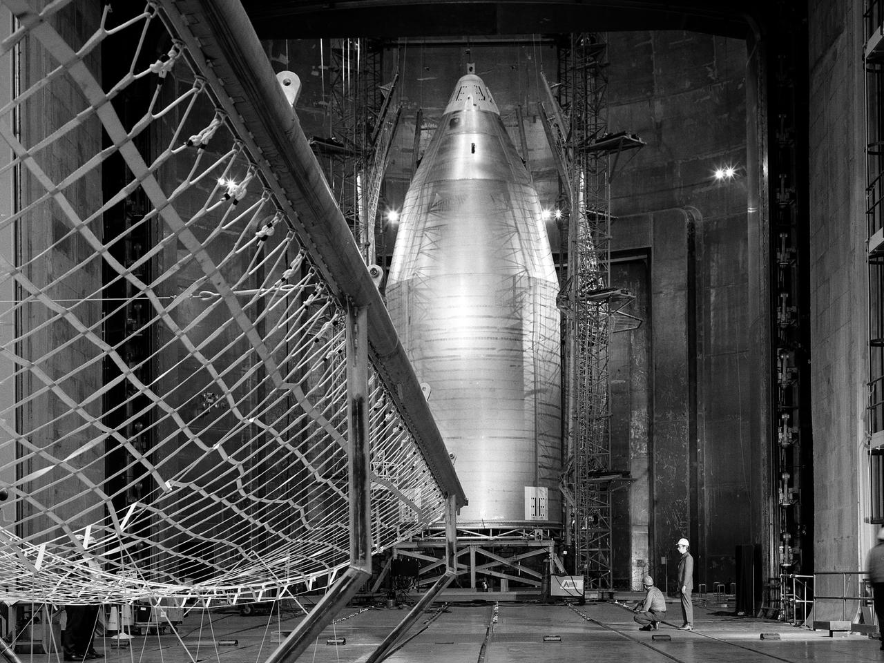
The 56-foot tall, 24,400-pound Skylab shroud installed in the Space Power Facility’s vacuum chamber at the National Aeronautics and Space Administration’s (NASA) Plum Brook Station. The Space Power Facility, which began operations in 1969, is the largest high vacuum chamber ever built. The chamber is 100 feet in diameter and 120 feet high. It can produce a vacuum deep enough to simulate the conditions at 300 miles altitude. The Space Power Facility was originally designed to test nuclear-power sources for spacecraft during long durations in a space atmosphere, but it was never used for that purpose. Payload shrouds are aerodynamic fairings to protect the payload during launch and ascent to orbit. The Skylab mission utilized the largest shroud ever attempted. Unlike previous launches, the shroud would not be jettisoned until the spacecraft reached orbit. NASA engineers designed these tests to verify the dynamics of the jettison motion in a simulated space environment. Fifty-four runs and three full-scale jettison tests were conducted from mid-September 1970 to June 1971. The shroud behaved as its designers intended, the detonators all fired, and early design issues were remedied by the final test. The Space Power Facility continues to operate today. The facility can sustain a high vacuum; simulate solar radiation via a 4-megawatt quartz heat lamp array, solar spectrum by a 400-kilowatt arc lamp, and cold environments. Test programs at the facility include high-energy experiments, shroud separation tests, Mars Lander system tests, deployable Solar Sail tests and International Space Station hardware tests.

Even with a major scientific expedition about to set sail one block away, Woods Hole, Massachusetts, hangs on to its centuries old New England charm. --- The <b><a href="http://naames.larc.nasa.gov/" rel="nofollow">North Atlantic Aerosols and Marine Ecosystems Study </a></b> (NAAMES) is a five year investigation to resolve key processes controlling ocean system function, their influences on atmospheric aerosols and clouds and their implications for climate. Michael Starobin joined the NAAMES field campaign on behalf of Earth Expeditions and NASA Goddard Space Flight Center’s Office of Communications. He presented stories about the important, multi-disciplinary research being conducted by the NAAMES team, with an eye towards future missions on the NASA drawing board. This is a NAAMES photo essay put together by Starobin, a collection of 49 photographs and captions. Photo and Caption Credit: Michael Starobin <b><a href="http://www.nasa.gov/audience/formedia/features/MP_Photo_Guidelines.html" rel="nofollow">NASA image use policy</a></b> <b><a href="http://www.nasa.gov/centers/goddard/home/index.html" rel="nofollow">NASA Goddard Space Flight Center</a></b> enables NASA’s mission through four scientific endeavors: Earth Science, Heliophysics, Solar System Exploration, and Astrophysics. Goddard plays a leading role in NASA’s accomplishments by contributing compelling scientific knowledge to advance the Agency’s mission. <b>Follow us on <a href="http://twitter.com/NASAGoddardPix" rel="nofollow">Twitter</a></b> <b>Like us on <a href="http://www.facebook.com/pages/Greenbelt-MD/NASA-Goddard/395013845897?ref=tsd" rel="nofollow">Facebook</a></b> <b>Find us on <a href="https://www.instagram.com/nasagoddard/?hl=en" rel="nofollow">Instagram</a></b>
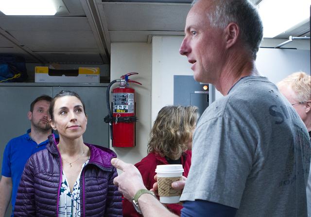
NAAMES Principal Investigator Mike Behrenfeld (right) speaks to his team the day before departure from Woods Hole. On the left is journalist Nicole Estaphan who sailed with the NAAMES team in November 2015. --- The <b><a href="http://naames.larc.nasa.gov/" rel="nofollow">North Atlantic Aerosols and Marine Ecosystems Study </a></b> (NAAMES) is a five year investigation to resolve key processes controlling ocean system function, their influences on atmospheric aerosols and clouds and their implications for climate. Michael Starobin joined the NAAMES field campaign on behalf of Earth Expeditions and NASA Goddard Space Flight Center’s Office of Communications. He presented stories about the important, multi-disciplinary research being conducted by the NAAMES team, with an eye towards future missions on the NASA drawing board. This is a NAAMES photo essay put together by Starobin, a collection of 49 photographs and captions. Photo and Caption Credit: Michael Starobin <b><a href="http://www.nasa.gov/audience/formedia/features/MP_Photo_Guidelines.html" rel="nofollow">NASA image use policy</a></b> <b><a href="http://www.nasa.gov/centers/goddard/home/index.html" rel="nofollow">NASA Goddard Space Flight Center</a></b> enables NASA’s mission through four scientific endeavors: Earth Science, Heliophysics, Solar System Exploration, and Astrophysics. Goddard plays a leading role in NASA’s accomplishments by contributing compelling scientific knowledge to advance the Agency’s mission. <b>Follow us on <a href="http://twitter.com/NASAGoddardPix" rel="nofollow">Twitter</a></b> <b>Like us on <a href="http://www.facebook.com/pages/Greenbelt-MD/NASA-Goddard/395013845897?ref=tsd" rel="nofollow">Facebook</a></b> <b>Find us on <a href="https://www.instagram.com/nasagoddard/?hl=en" rel="nofollow">Instagram</a></b>

NASA image release April 22, 2010 This brand new Hubble photo is of a small portion of one of the largest seen star-birth regions in the galaxy, the Carina Nebula. Towers of cool hydrogen laced with dust rise from the wall of the nebula. The scene is reminiscent of Hubble's classic "Pillars of Creation" photo from 1995, but is even more striking in appearance. The image captures the top of a three-light-year-tall pillar of gas and dust that is being eaten away by the brilliant light from nearby bright stars. The pillar is also being pushed apart from within, as infant stars buried inside it fire off jets of gas that can be seen streaming from towering peaks like arrows sailing through the air. Credit: NASA, ESA, and M. Livio and the Hubble 20th Anniversary Team (STScI) To read learn more about this image go to: <a href="http://www.nasa.gov/mission_pages/hubble/science/hubble20th-img.html" rel="nofollow">www.nasa.gov/mission_pages/hubble/science/hubble20th-img....</a> <b><a href="http://www.nasa.gov/audience/formedia/features/MP_Photo_Guidelines.html" rel="nofollow">NASA image use policy.</a></b> <b><a href="http://www.nasa.gov/centers/goddard/home/index.html" rel="nofollow">NASA Goddard Space Flight Center</a></b> enables NASA’s mission through four scientific endeavors: Earth Science, Heliophysics, Solar System Exploration, and Astrophysics. Goddard plays a leading role in NASA’s accomplishments by contributing compelling scientific knowledge to advance the Agency’s mission. <b>Follow us on <a href="http://twitter.com/NASAGoddardPix" rel="nofollow">Twitter</a></b> <b>Like us on <a href="http://www.facebook.com/pages/Greenbelt-MD/NASA-Goddard/395013845897?ref=tsd" rel="nofollow">Facebook</a></b> <b>Find us on <a href="http://instagram.com/nasagoddard?vm=grid" rel="nofollow">Instagram</a></b>
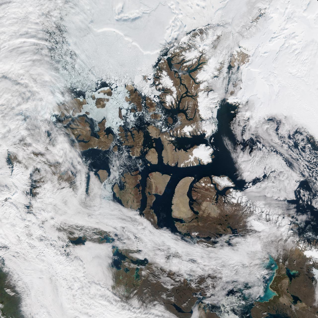
There was a time when the Northwest Passage was a sort of maritime Holy Grail, a route so desired and sought after, but so elusive. For most of the recorded history of North America, the Passage has been nearly impassable and often deadly. But with the modernization of ships and the warming of the Earth, cruising and sailing through the Canadian Archipelago from Baffin Bay to the Beaufort Sea has grown more common and easier. But it’s not necessarily easy. The top image above shows the Northwest Passage as it appeared on August 31, 2015, to the Visible Infrared Imaging Radiometer Suite (VIIRS) on the Suomi-NPP satellite. Read more: <a href="http://earthobservatory.nasa.gov/IOTD/view.php?id=86589" rel="nofollow">earthobservatory.nasa.gov/IOTD/view.php?id=86589</a> NASA Earth Observatory images by Jesse Allen, using VIIRS data from the Suomi National Polar-orbiting Partnership. Suomi NPP is the result of a partnership between NASA, the National Oceanic and Atmospheric Administration, and the Department of Defense. <b><a href="http://www.nasa.gov/audience/formedia/features/MP_Photo_Guidelines.html" rel="nofollow">NASA image use policy.</a></b> <b><a href="http://www.nasa.gov/centers/goddard/home/index.html" rel="nofollow">NASA Goddard Space Flight Center</a></b> enables NASA’s mission through four scientific endeavors: Earth Science, Heliophysics, Solar System Exploration, and Astrophysics. Goddard plays a leading role in NASA’s accomplishments by contributing compelling scientific knowledge to advance the Agency’s mission. <b>Follow us on <a href="http://twitter.com/NASAGoddardPix" rel="nofollow">Twitter</a></b> <b>Like us on <a href="http://www.facebook.com/pages/Greenbelt-MD/NASA-Goddard/395013845897?ref=tsd" rel="nofollow">Facebook</a></b> <b>Find us on <a href="http://instagrid.me/nasagoddard/?vm=grid" rel="nofollow">Instagram</a></b>