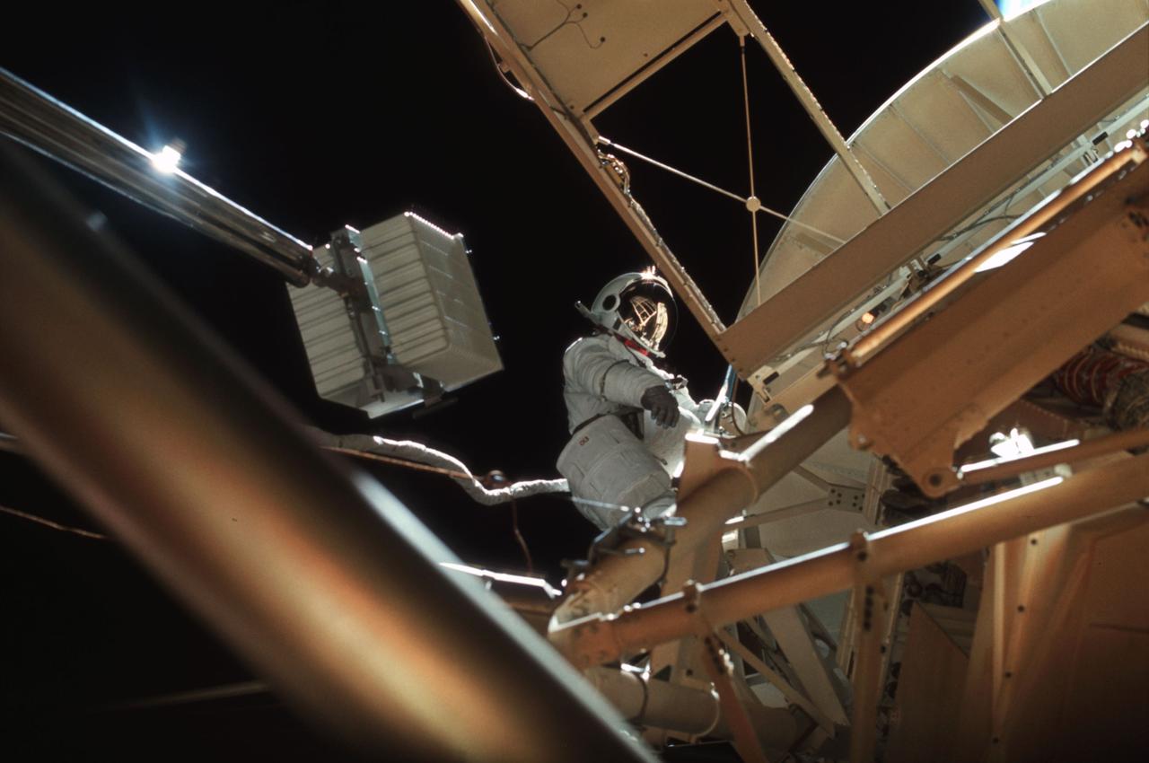
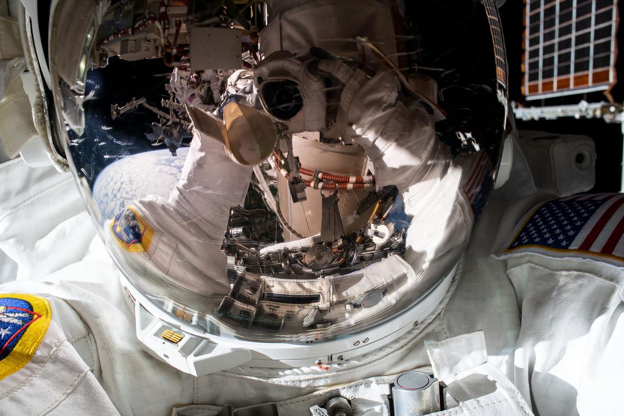
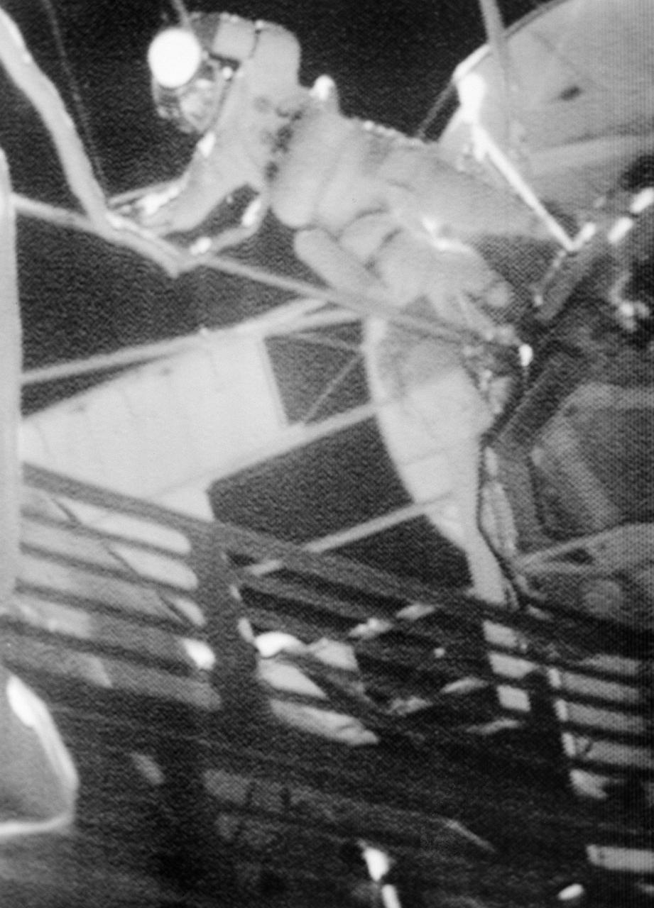
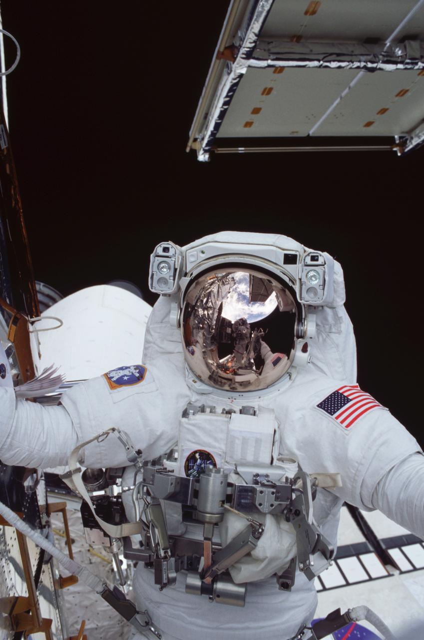
SL3-117-2109 (6 Aug. 1973) --- Scientist-astronaut Owen K. Garriott, Skylab 3 science pilot, participates in the Aug. 6, 1973 extravehicular activity (EVA) during which he and astronaut Jack Lousma, Skylab 3 pilot, deployed the twin pole solar shield to help shade the Orbital Workshop (OWS). Note the reflection of the solar shield in Garriott's helmet visor. Photo credit: NASA
Scientist-Astronaut Owen K. Garriott, Skylab 3 science pilot, participates in the August 6, 1973 extravehicular activity (EVA) during which he and Astronaut Jack Lousma, Skylab pilot, deployed the twin pole solar shield to help shade the Orbital Workshop (OWS). Note the reflection of the solar shield in Garriett's helmet visor.
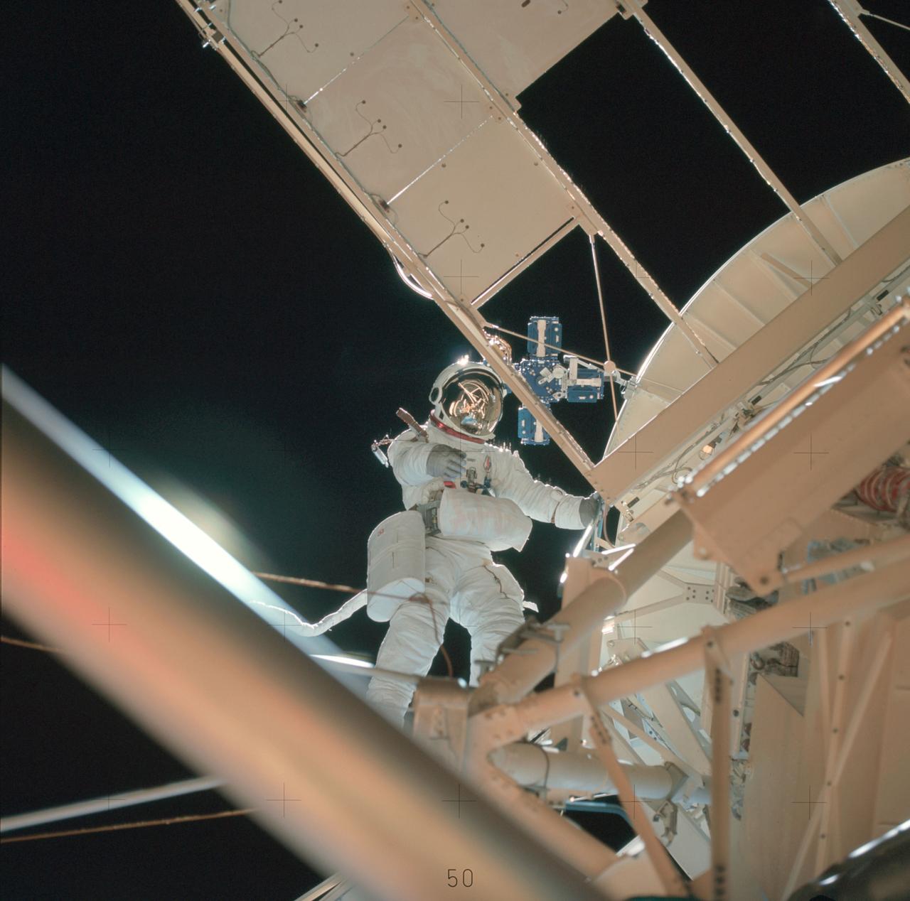
SL3-118-2182 (6 Aug. 1973) --- Skylab 3 astronaut participates in the Aug. 6, 1973 extravehicular activity (EVA) during which the twin pole solar shield was deployed to help shade the Orbital Workshop (OWS). Photo credit: NASA

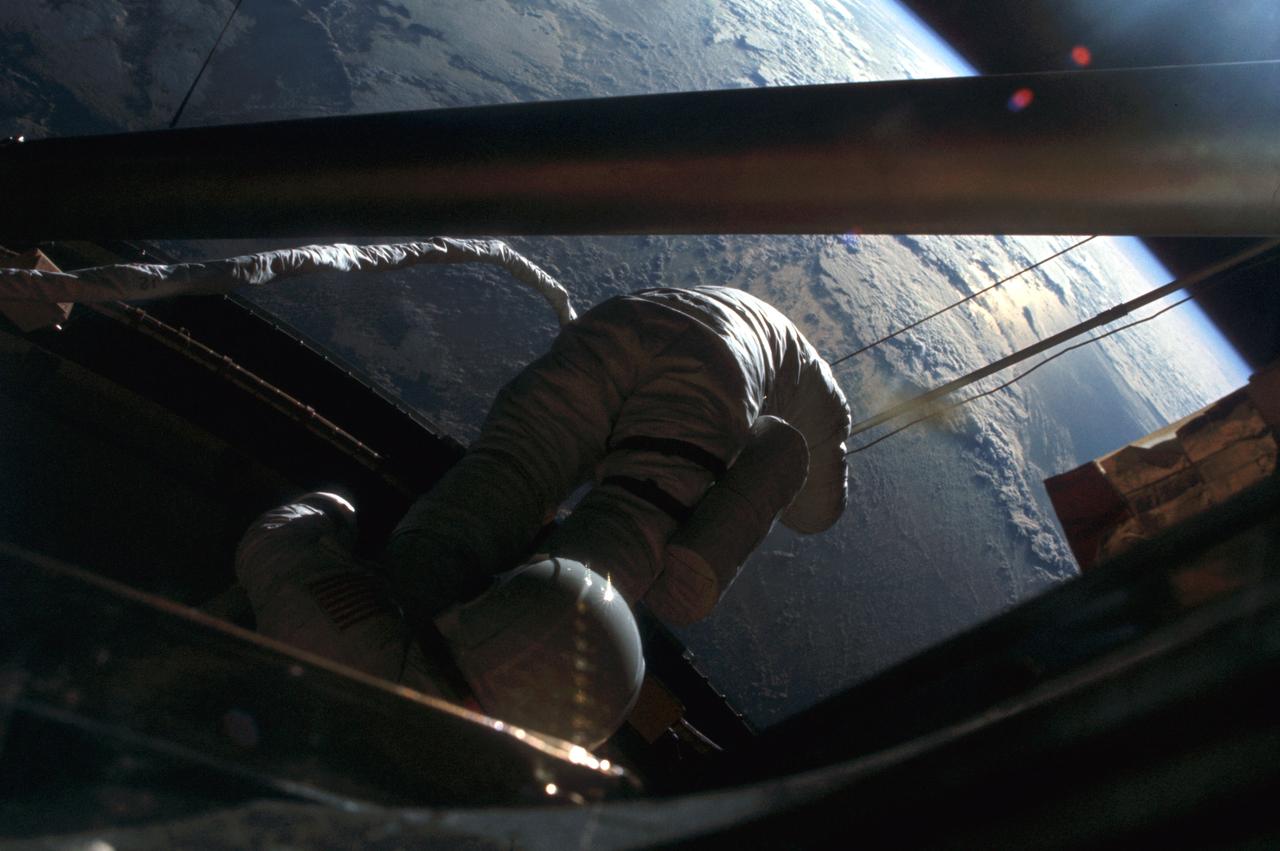
SL3-115-1833 (6 Aug. 1973) --- Astronaut Jack R. Lousma, Skylab 3 pilot, participates in the Aug. 6, 1973, extravehicular activity (EVA) during which he and astronaut Owen K. Garriott, science pilot, deployed the twin pole solar shield to help shade the Orbital Workshop (OWS). Note the striking reflection of the Earth in Lousma?s helmet visor. This photograph was taken with a 70mm hand-held Hasselblad camera. Photo credit: NASA
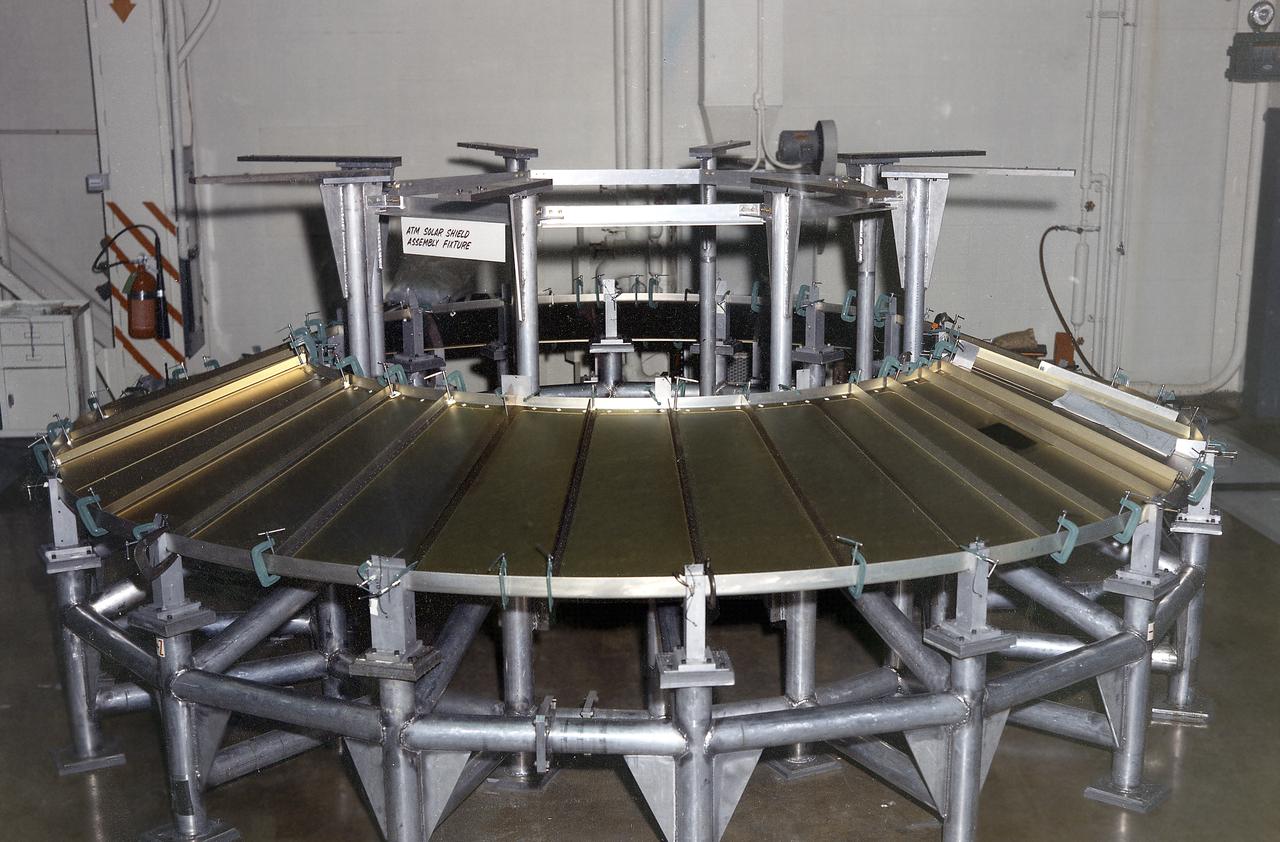
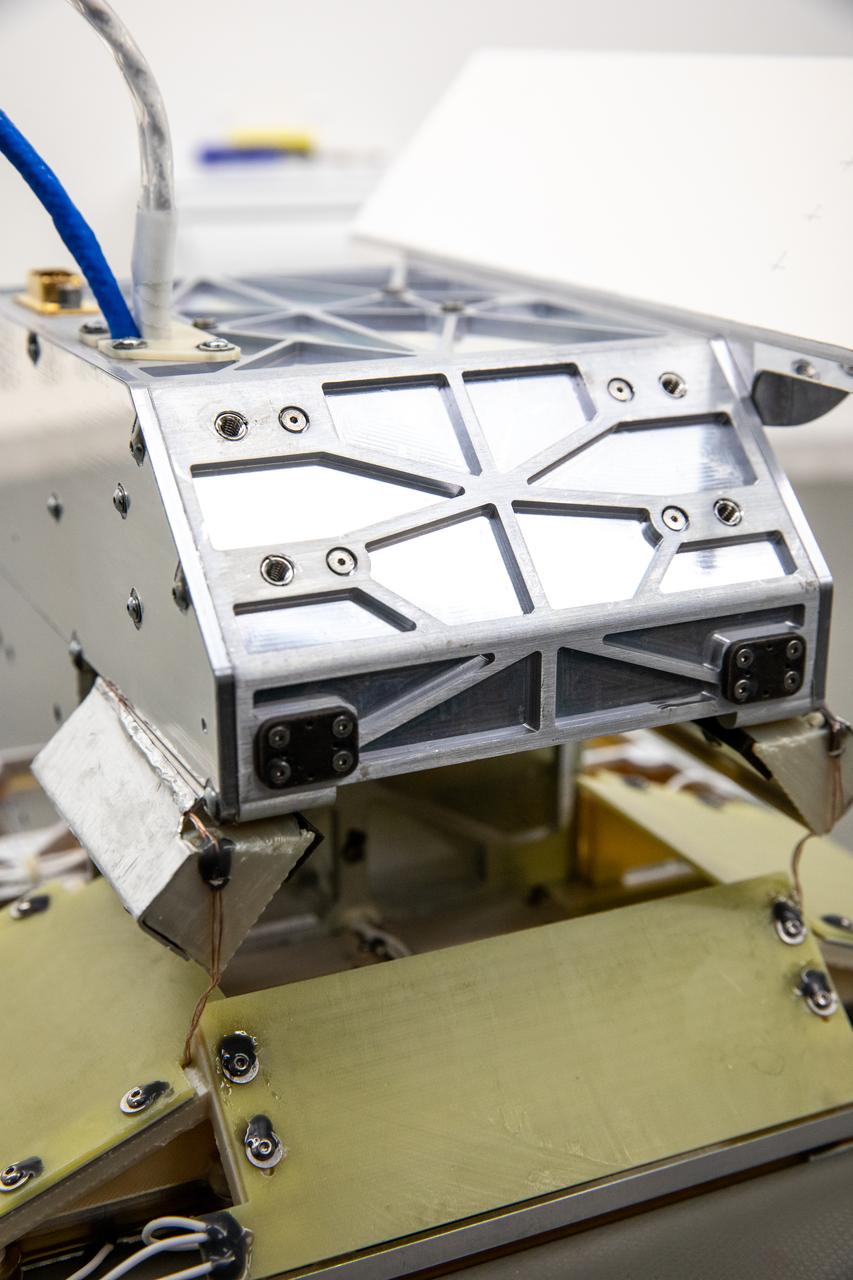
The Apollo Telescope Mount (ATM) was designed and developed by the Marshall Space Flight Center and served as the primary scientific instrument unit aboard Skylab (1973-1979). The ATM consisted of eight scientific instruments as well as a number of smaller experiments. One scientific instrument was the ATM solar shield that formed the base for the rack/frame instrument and the instrument canister. The solar shield contained aperture doors for each instrument to protect against solar radiation and space contamination.
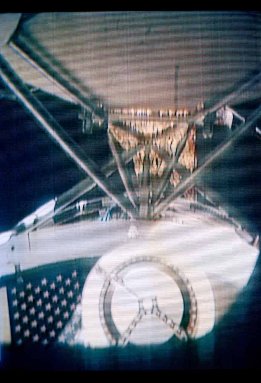
S73-26773 (26 May 1973) --- The deployment of the ?parasol? solar shield, a sunshade to help cool the overheated Orbital Workshop of the Skylab 1 space station cluster in Earth orbit, can be seen in the reproduction taken from a color television transmission made by a TV camera aboard the space station. The camera is in the Command Module; and the view is looking through the truss of the Apollo Telescope Mount. The sunshade is only partially deployed in this picture. The solar shield was pushed up through the OWS solar scientific airlock. The canopy of the ?parasol? measures 24 feet by 22 feet. Photo credit: NASA
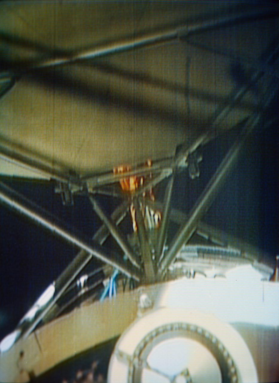
S73-26775 (26 May 1973) --- The deployment of the "parasol" solar shield, a sunshade to help cool the overheated Orbital Workshop of the Skylab 1 space station cluster in Earth orbit, can be seen in the reproduction taken from a color television transmission made by a TV camera aboard the space station. The camera is in the Command Module; and the view is looking through the truss of the Apollo Telescope Mount. The sunshade is only partially deployed in this picture. Photo credit: NASA

This poster artfully depicts Solar Surfing, an early stage NASA study to support potential future missions that could travel closer to the Sun’s surface than ever before. The solar transition region, a very thin layer near the Sun’s surface, is of great interest to heliophysicists. In this zone, temperatures range from 10,000 to 1.8 million degrees Fahrenheit. The NASA Innovative Advanced Concepts (NIAC) program funds a study by a team at NASA’s Kennedy Space Center in Florida to further research a novel, highly reflective coating for a solar shield that could allow spacecraft to approach the Sun close enough to investigate this exciting region – about 500,000 miles from the surface. The better heliophysicists understand the Sun and how it generates energy, the better they can make predictions of the Sun’s effect on our planet – and improve our everyday communications, electronics, and transportation.
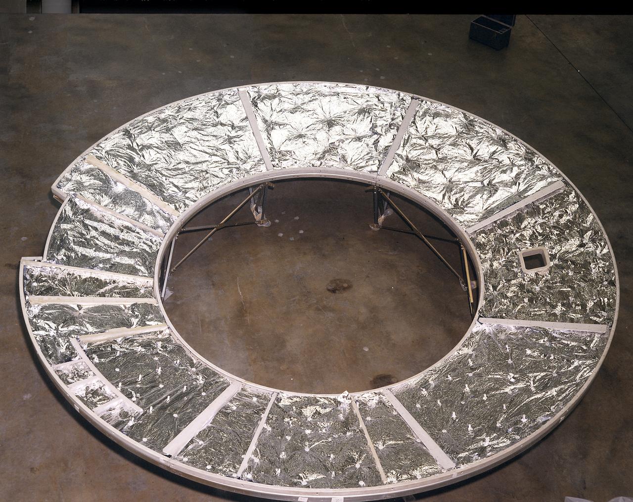
The Apollo Telescope Mount (ATM) was designed and constructed at the Marshall Space Flight Center and served as the primary scientific instrument unit aboard Skylab. The ATM consisted of eight scientific instruments as well as a number of smaller experiments. This photograph shows the flight unit solar shield for the ATM that formed the base for the rack, a complex frame, and the canister that contained the instruments.
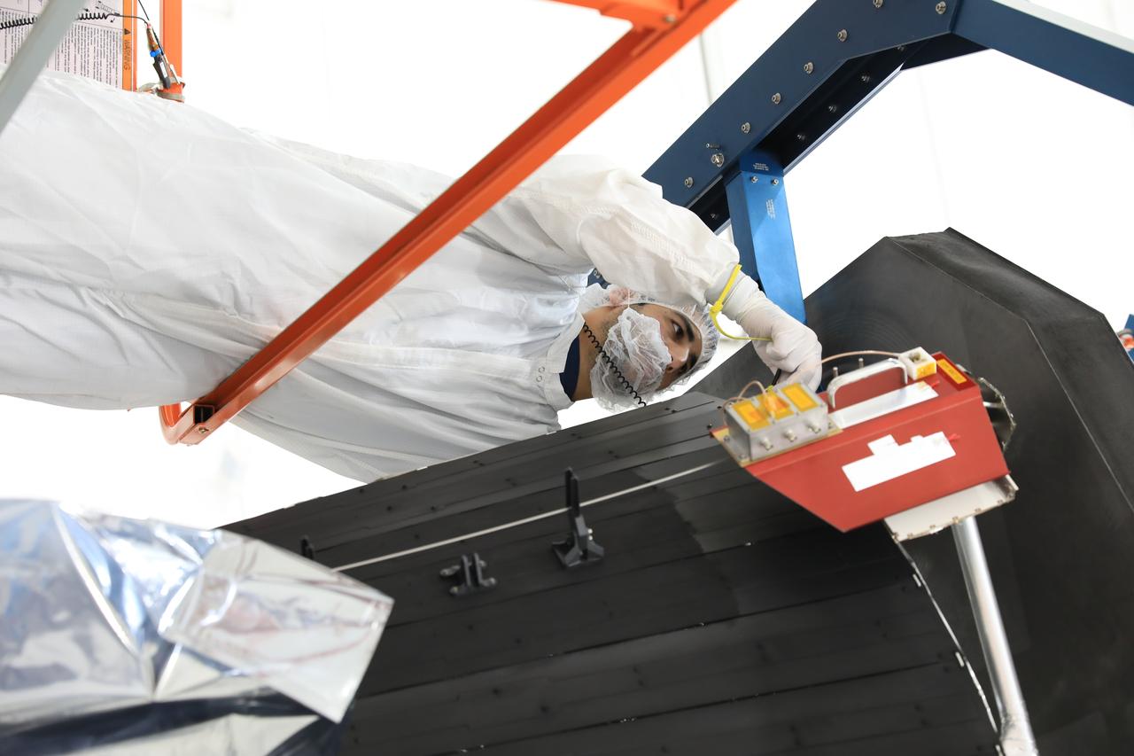
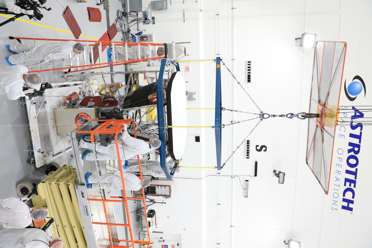
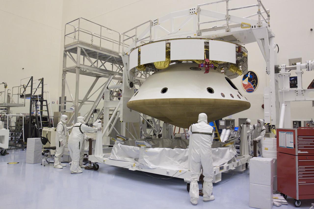
In the Astrotech processing facility in Titusville, Florida, near NASA's Kennedy Space Center, on Wednesday, June 27, 2018, technicians and engineers install the heat shield on NASA's Parker Solar Probe. The Parker Solar Probe will launch on a United Launch Alliance Delta IV Heavy rocket from Space Launch Complex 37 at Cape Canaveral Air Force Station in Florida no earlier than Aug. 4, 2018. The mission will perform the closest-ever observations of a star when it travels through the Sun's atmosphere, called the corona. The probe will rely on measurements and imaging to revolutionize our understanding of the corona and the Sun-Earth connection.
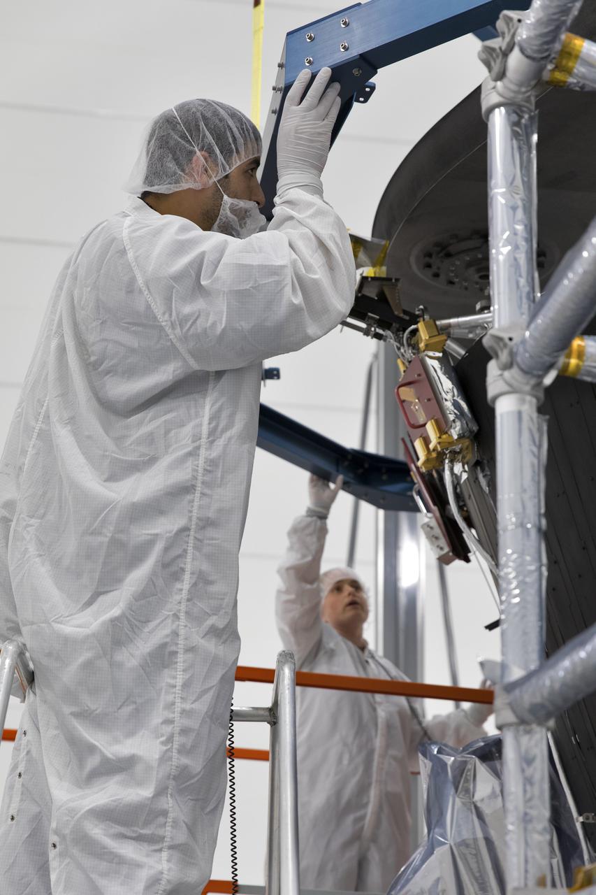
In the Astrotech processing facility in Titusville, Florida, near NASA's Kennedy Space Center, on Wednesday, June 27, 2018, technicians and engineers install the heat shield on NASA's Parker Solar Probe. The Parker Solar Probe will launch on a United Launch Alliance Delta IV Heavy rocket from Space Launch Complex 37 at Cape Canaveral Air Force Station in Florida no earlier than Aug. 4, 2018. The mission will perform the closest-ever observations of a star when it travels through the Sun's atmosphere, called the corona. The probe will rely on measurements and imaging to revolutionize our understanding of the corona and the Sun-Earth connection.
In the Astrotech processing facility in Titusville, Florida, near NASA's Kennedy Space Center, on Wednesday, June 27, 2018, technicians and engineers install the heat shield on NASA's Parker Solar Probe. The Parker Solar Probe will launch on a United Launch Alliance Delta IV Heavy rocket from Space Launch Complex 37 at Cape Canaveral Air Force Station in Florida no earlier than Aug. 4, 2018. The mission will perform the closest-ever observations of a star when it travels through the Sun's atmosphere, called the corona. The probe will rely on measurements and imaging to revolutionize our understanding of the corona and the Sun-Earth connection.
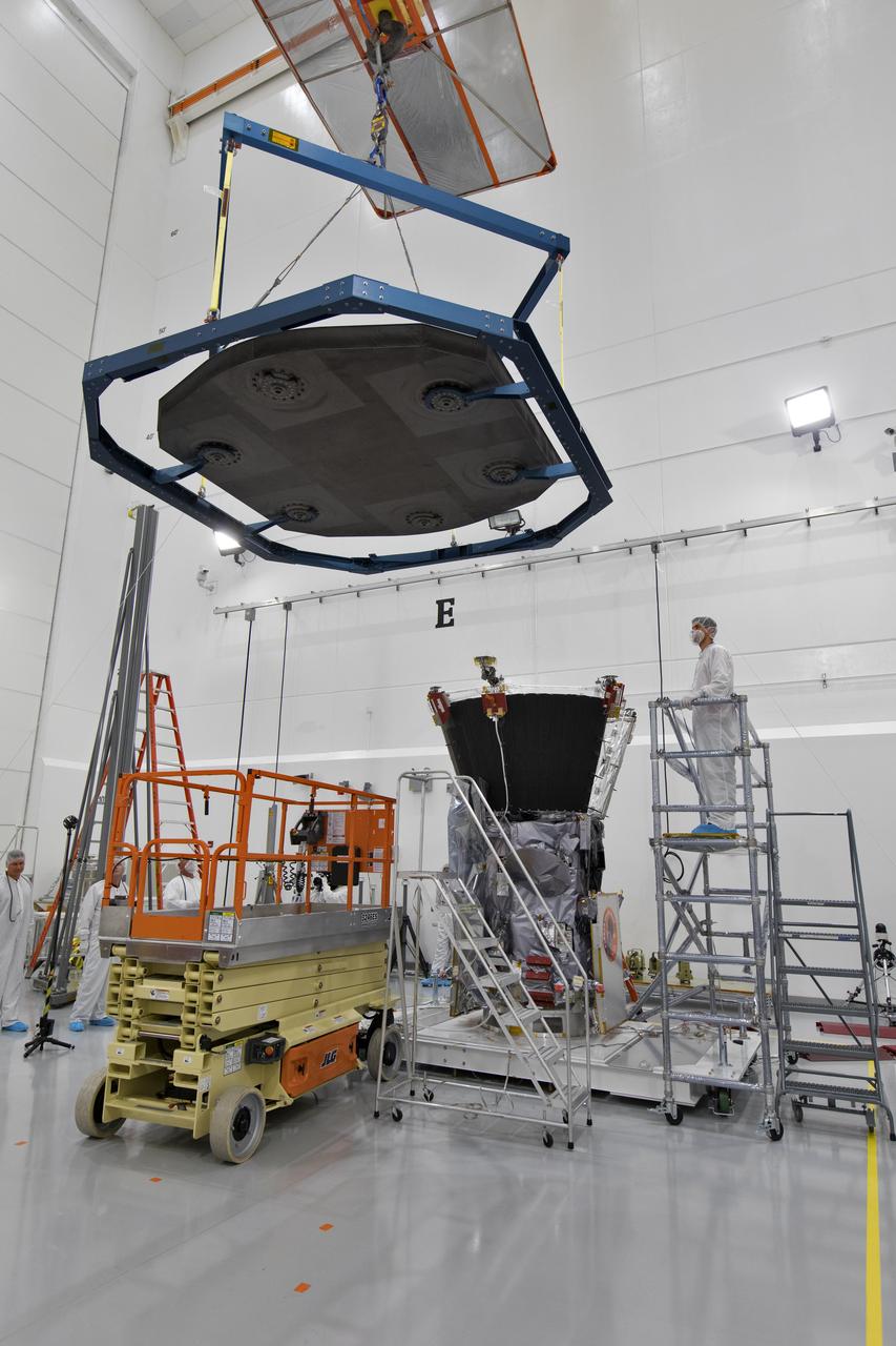
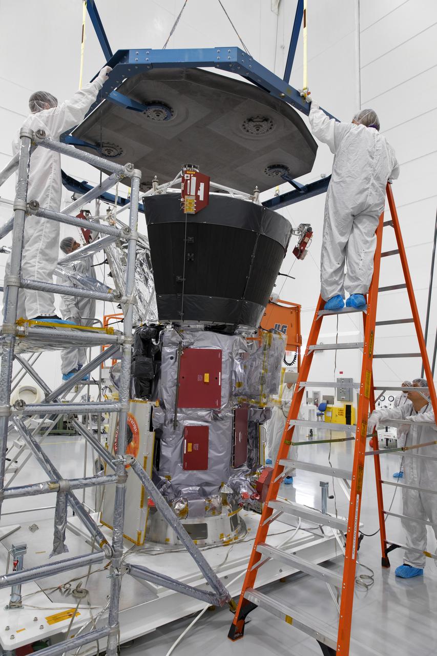
In the Astrotech processing facility in Titusville, Florida, near NASA's Kennedy Space Center, on Wednesday, June 27, 2018, technicians and engineers use a crane to install the heat shield on NASA's Parker Solar Probe. The Parker Solar Probe will launch on a United Launch Alliance Delta IV Heavy rocket from Space Launch Complex 37 at Cape Canaveral Air Force Station in Florida no earlier than Aug. 4, 2018. The mission will perform the closest-ever observations of a star when it travels through the Sun's atmosphere, called the corona. The probe will rely on measurements and imaging to revolutionize our understanding of the corona and the Sun-Earth connection.
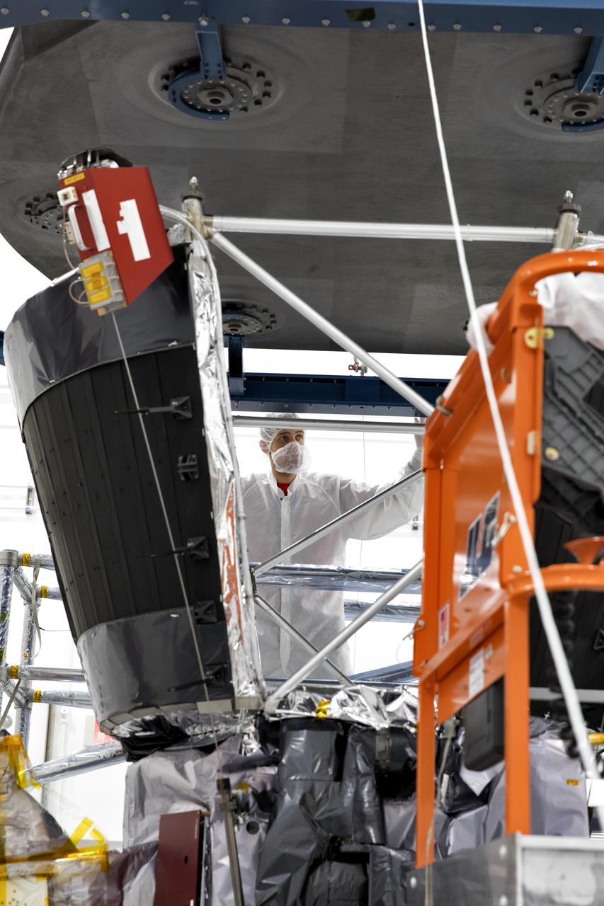
In the Astrotech processing facility in Titusville, Florida, near NASA's Kennedy Space Center, on Wednesday, June 27, 2018, technicians and engineers install the heat shield on NASA's Parker Solar Probe. The Parker Solar Probe will launch on a United Launch Alliance Delta IV Heavy rocket from Space Launch Complex 37 at Cape Canaveral Air Force Station in Florida no earlier than Aug. 4, 2018. The mission will perform the closest-ever observations of a star when it travels through the Sun's atmosphere, called the corona. The probe will rely on measurements and imaging to revolutionize our understanding of the corona and the Sun-Earth connection.
In the Astrotech processing facility in Titusville, Florida, near NASA's Kennedy Space Center, on Wednesday, June 27, 2018, technicians and engineers use a crane to install the heat shield on NASA's Parker Solar Probe. The Parker Solar Probe will launch on a United Launch Alliance Delta IV Heavy rocket from Space Launch Complex 37 at Cape Canaveral Air Force Station in Florida no earlier than Aug. 4, 2018. The mission will perform the closest-ever observations of a star when it travels through the Sun's atmosphere, called the corona. The probe will rely on measurements and imaging to revolutionize our understanding of the corona and the Sun-Earth connection.
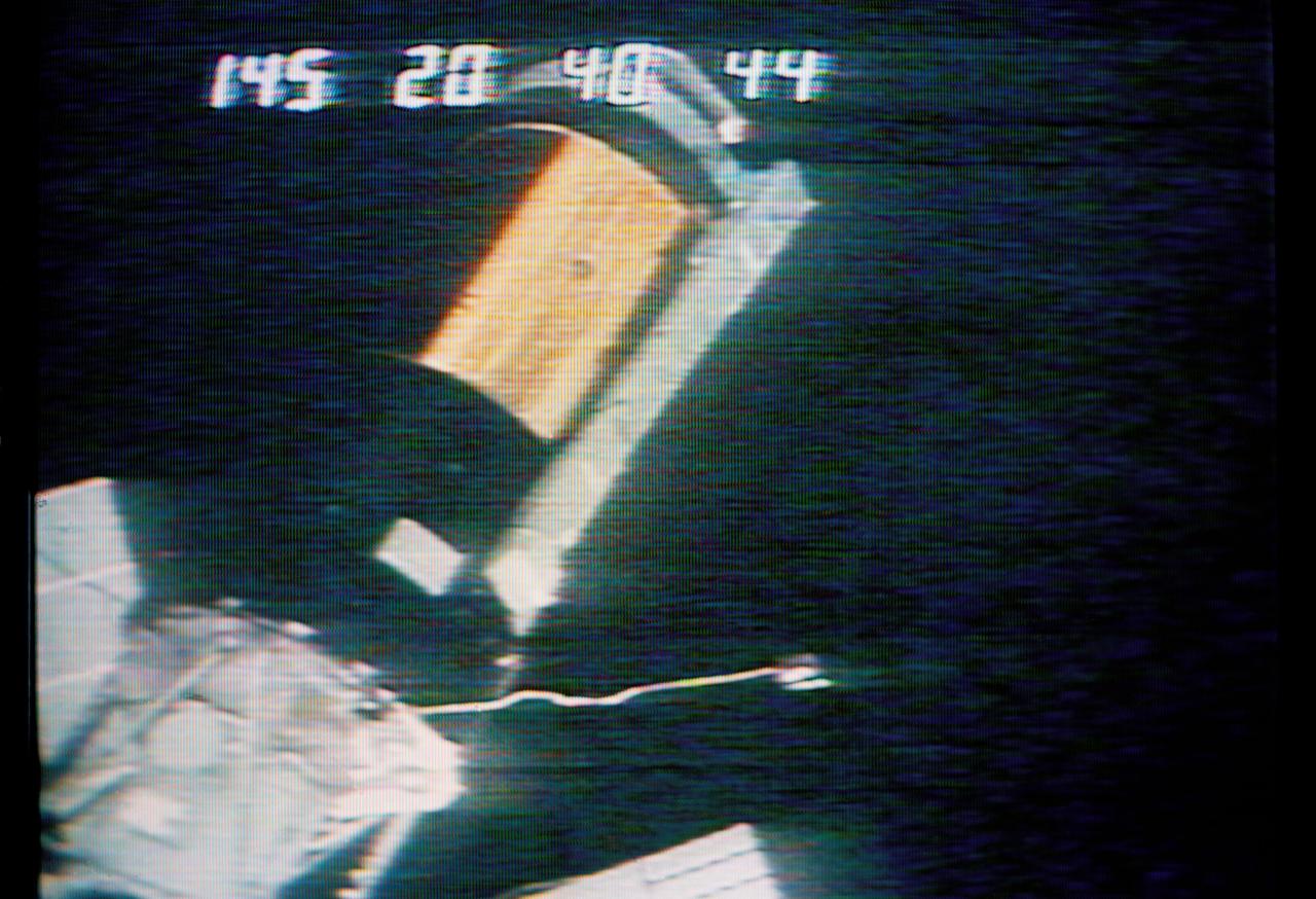
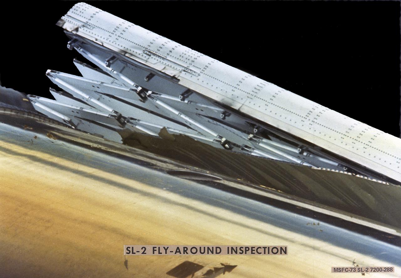
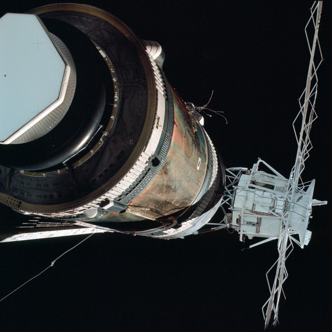
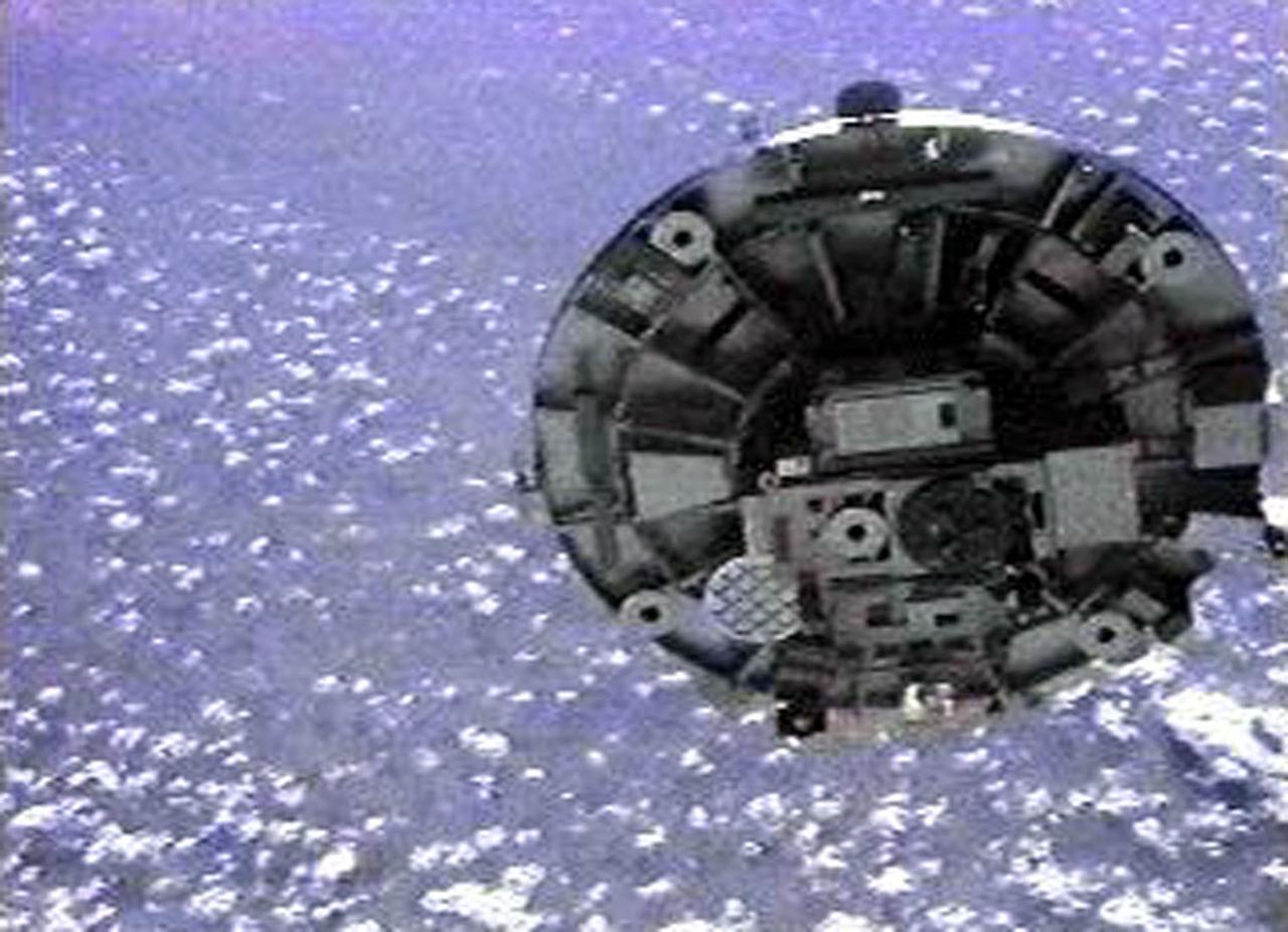
S73-26738 (25 May 1973) --- A close-up view of the Skylab 1 space station cluster can be seen in this reproduction taken from a color television transmission made by a TV camera aboard the Skylab 2 Command Module during its ?fly-around? inspection of the cluster. The numbers across the top of the picture indicate the Skylab 1 ground lapse time. Note the missing portion of the micrometeoroid shield on the Orbital Workshop. The shield area was reported to be solid gold by the Skylab 2 crewmen. A cable appears to be wrapped around the damaged OWS solar array system wing. The crewmen reported that the other OWS solar panel was completely gone, with only tubes and wiring sticking out. One of the discone antennas extends out form the Airlock Module. The Multiple Docking Adapter is in the lower left corner of the picture. A portion of a solar panel on the Apollo Telescope Mount is visible at the bottom and at the left edge. In their ?fly around? inspection the crewmen noted that portions of the micrometeoroid shield had slid back underneath the OWS solar wing. Photo credit: NASA
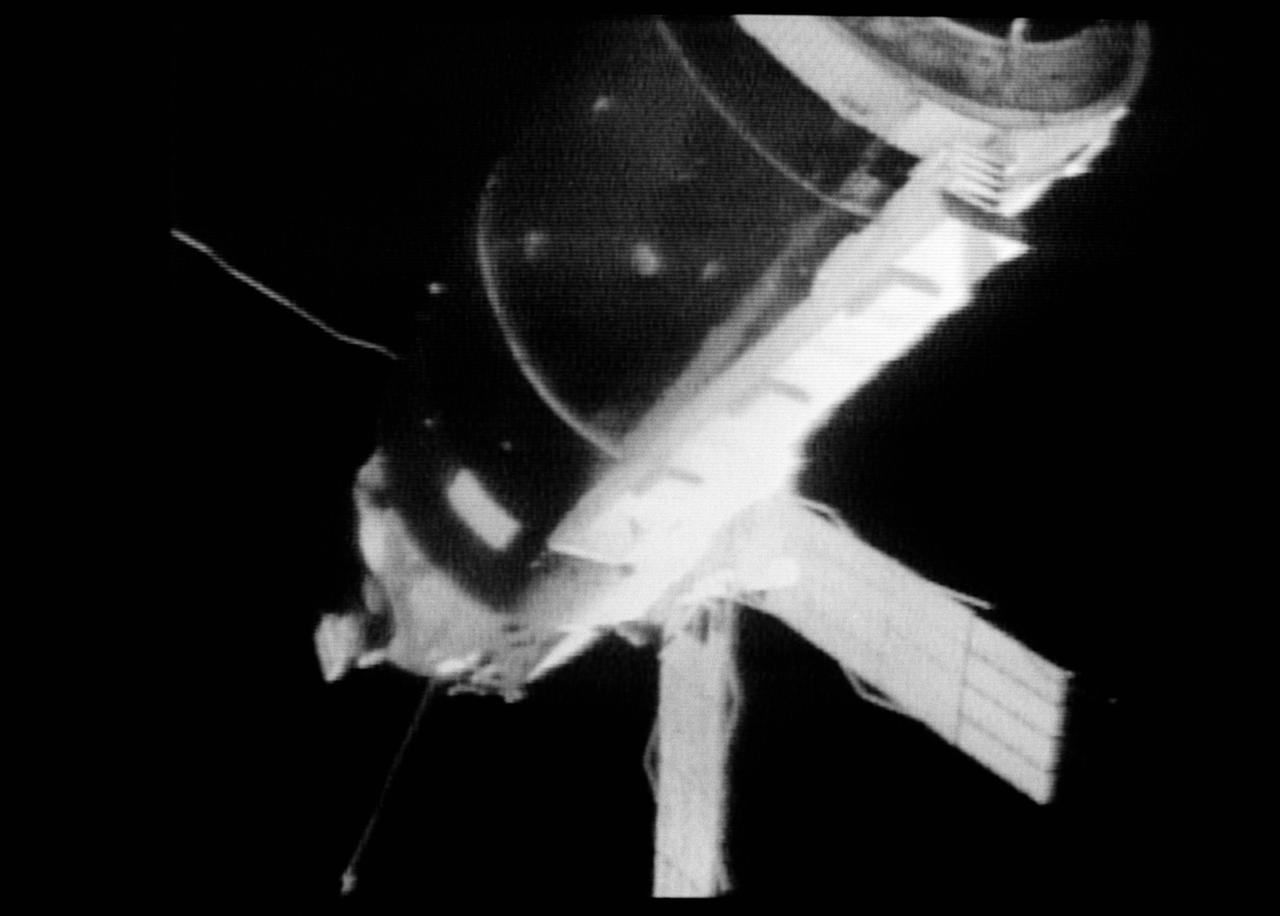
S73-27182 (25 May 1973) --- A close-up view of the Skylab 1 space station cluster can be seen in this reproduction taken from a color television transmission made by a TV camera aboard the Skylab 2 Command Module during its "fly around" inspection of the cluster. This view has been enhanced. At left center the damaged solar array system wing on the Orbital Workshop (OWS) appears to be partly folded. In their preliminary inspection the crewmen noted that portions of the micrometeoroid shield had slid back underneath the OWS solar wing. Solar panels on the Apollo Telescope Mount extend out at the top center. Photo credit: NASA

SL3-122-2611 (22 Sept. 1973) --- Astronaut Alan L. Bean, Skylab 3 commander, participates in the final extravehicular activity (EVA) for that mission, during which a variety of tasks were performed. Here, Bean is near the Apollo Telescope Mount (ATM) during final film change out for the giant telescope facility. Astronaut Owen K. Garriott, who took the picture, is reflected in Bean's helmet visor. The reflected Earth disk in Bean's visor is so clear that the Red Sea and Nile River area can delineated. Photo credit: NASA
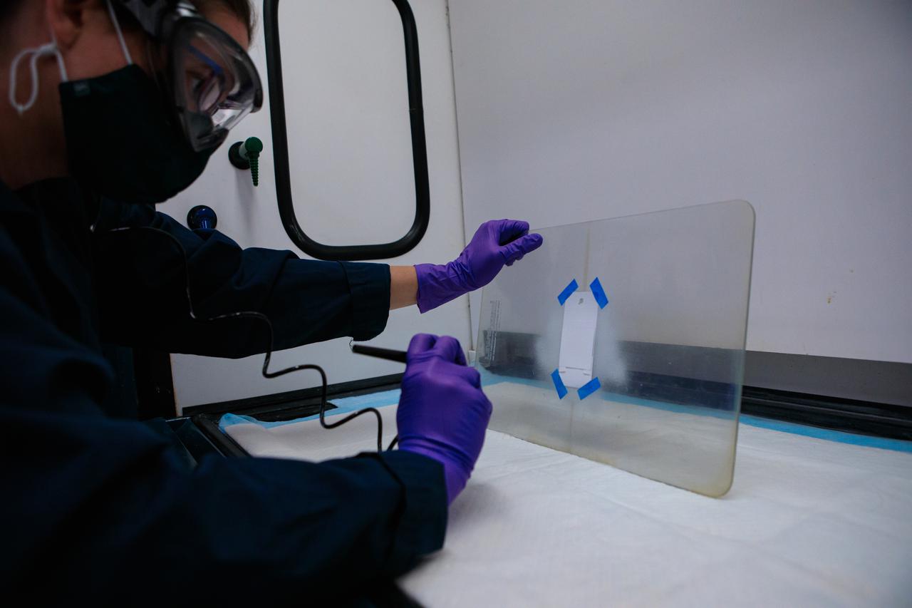
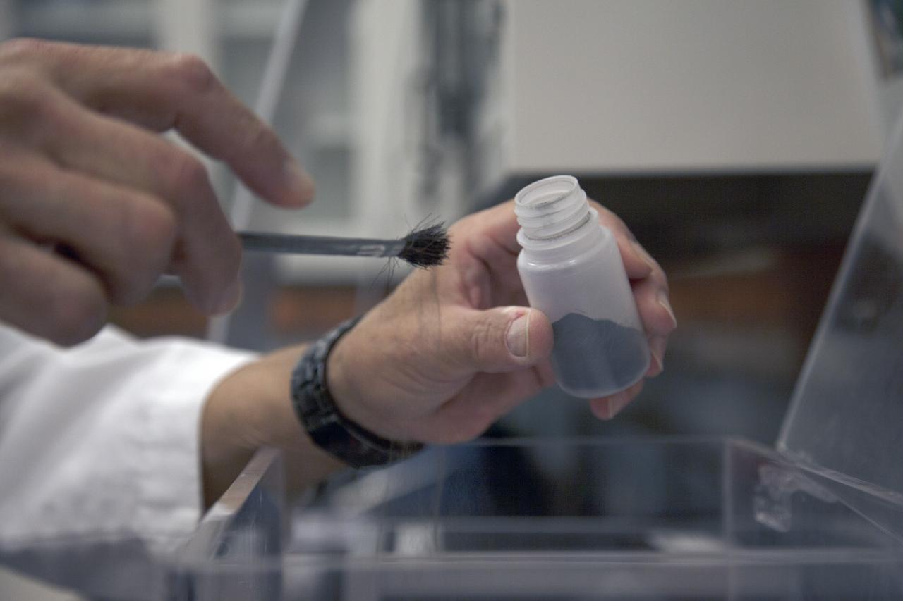
Inside a laboratory at the Neil Armstrong Operations and Checkout Building at NASA’s Kennedy Space Center in Florida, research scientist Sarah Snyder applies a selective surface coating to an Electrodynamic Dust Shield (EDS) on March 31, 2021. This is one of several concurrent activities preparing dust shield samples for testing in space. Dust mitigation technologies could one day be applied to diminish dust hazards on lunar surface systems such as cameras, solar panels, spacesuits, and instrumentation, enabling sustainable exploration of the Moon under the Artemis program.
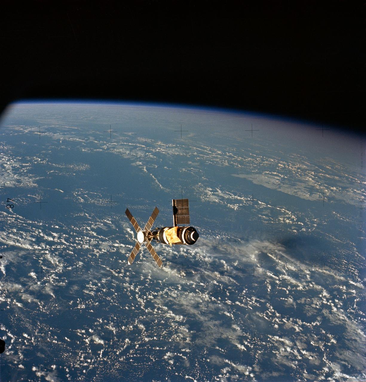
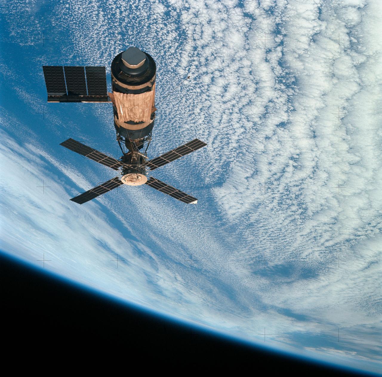
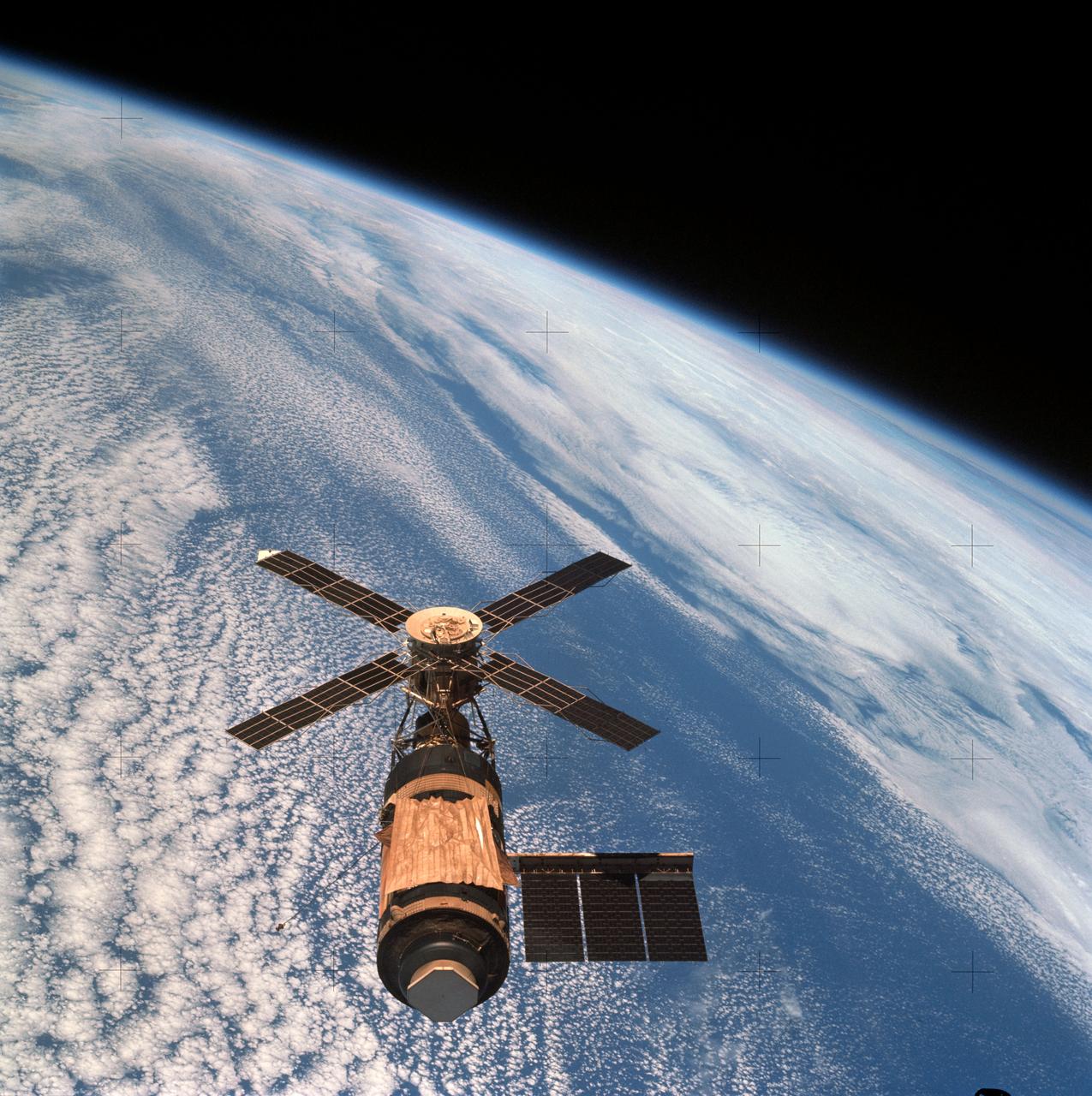
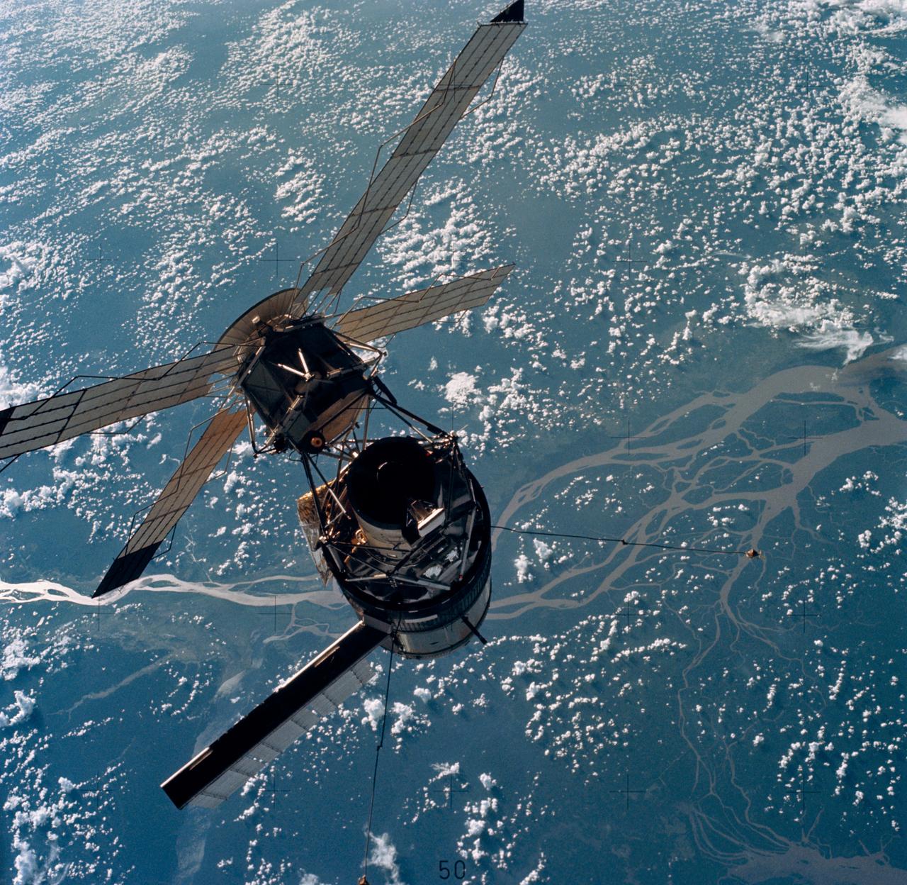
SL2-07-651 (22 June 1973) --- This overhead view of the Skylab Space Station was taken from the Departing Skylab Command/Service Module during the Skylab 2's final fly-around inspection. The single solar panel is quite evident as well as the parasol solar shield, rigged to replace the missing micrometeoroid shield. Both the second solar panel and the micrometeoroid shield were torn away during a mishap in the original Skylab 1 liftoff and orbital insertion. Photo credit: NASA
SL2-07-667 (22 June 1973) --- This overhead view of the Skylab Space Station was taken from the Departing Skylab Command/Service Module during the Skylab 2's final fly-around inspection. The single solar panel is quite evident as well as the parasol solar shield, rigged to replace the missing micrometeoroid shield. Both the second solar panel and the micrometeoroid shield were torn away during a mishap in the original Skylab 1 liftoff and orbital insertion. Photo credit: NASA
This view of the Skylab Orbital Space Station was taken from the Skylab 2 Command/Service Module during it's initial fly around inspection. The micrometeoroid shield can be seen to be missing and a parasol solar shield was later fitted in its place. The damaged and partially deployed solar array, in the center of the scene, can be seen to be restrained by a strap that was later cut during an early EVA, allowing the panel to fully deploy.
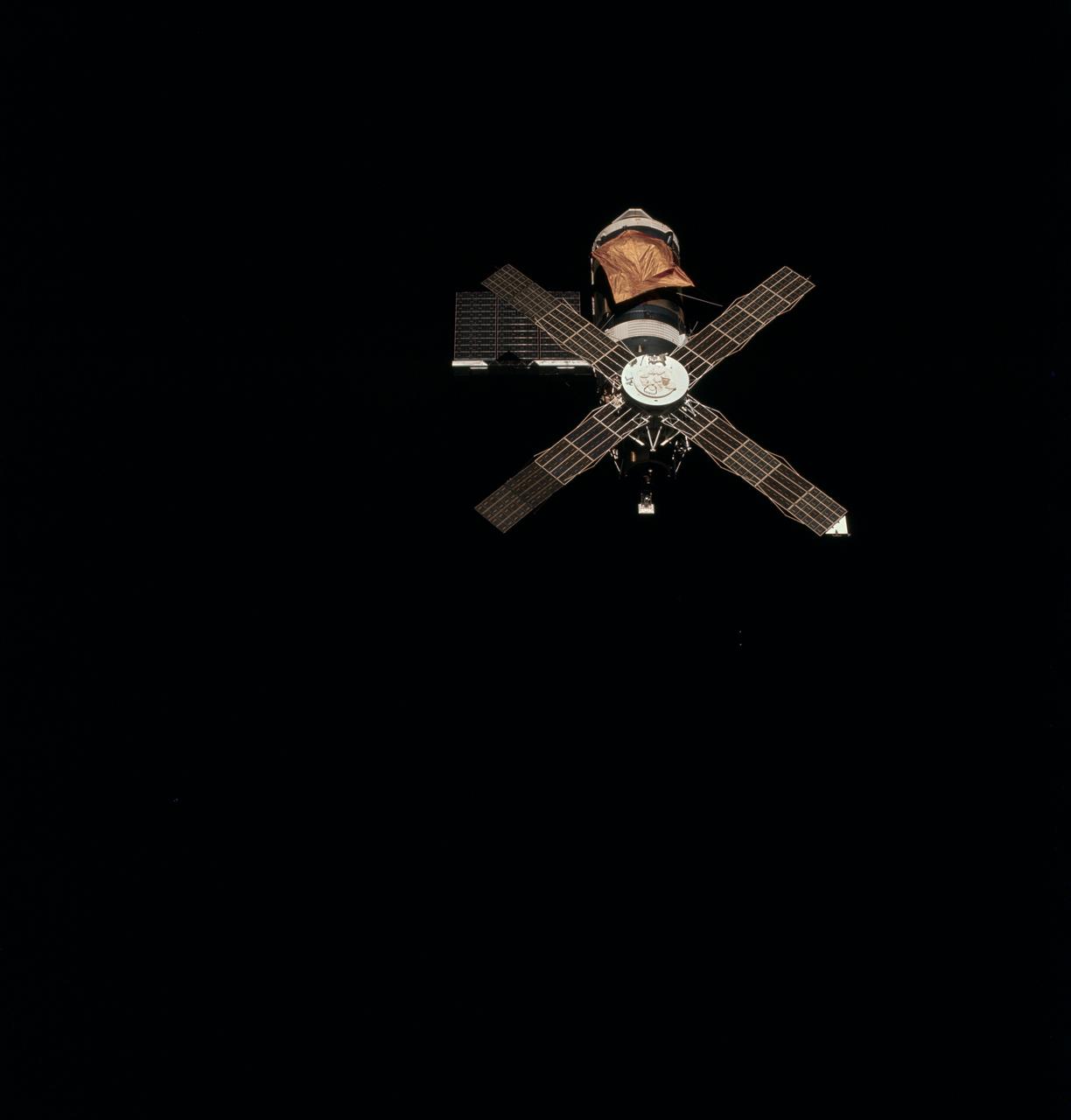
SL2-X7-615 (22 June 1973) --- An overhead view of the Skylab 1 space station cluster in Earth orbit photographed from the Skylab 2 Command/Service Module during the final ?fly around? inspection by the CSM. The space station is sharply contrasted against a black sky background. Note the deployed parasol solar shield which shades the Orbital Workshop where the micrometeoroid shield is missing. The one remaining OWS solar array system wing has been fully deployed successfully. The OWS solar panel on the opposite side is missing completely. Photo credit: NASA
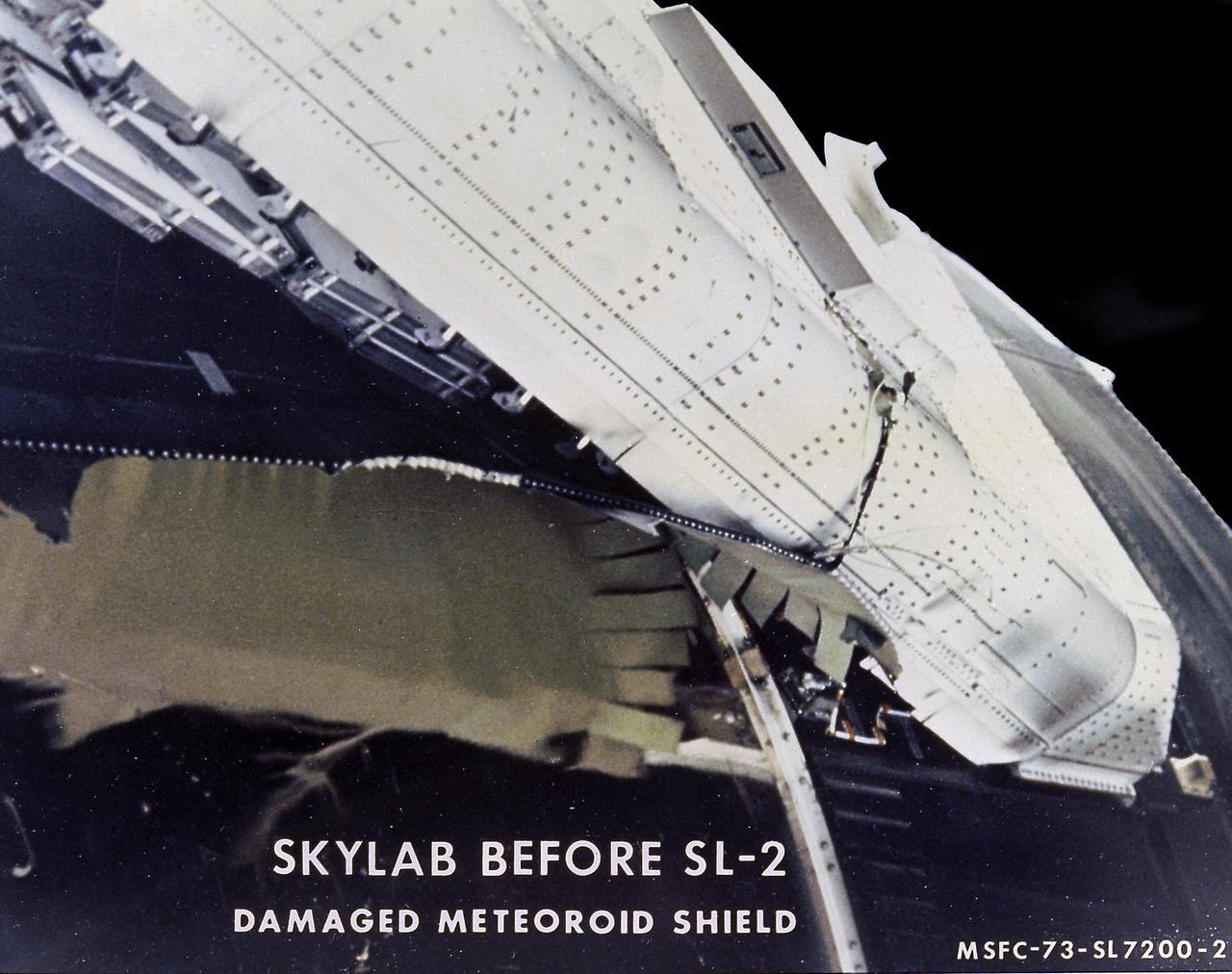
The Saturn V vehicle, carrying the unmarned orbital workshop for the Skylab-1 mission, lifted off successfully and all systems performed normally. Sixty-three seconds into flight, engineers in the operation support and control center saw an unexpected telemetry indication that signalled that damages occurred on one solar array and the micrometeoroid shield during the launch. The micrometeoroid shield, a thin protective cylinder surrounding the workshop protecting it from tiny space particles and the sun's scorching heat, ripped loose from its position around the workshop. This caused the loss of one solar wing and jammed the other. Still unoccupied, the Skylab was stricken with the loss of the heat shield and sunlight beat mercilessly on the lab's sensitive skin. Internal temperatures soared, rendering the station uninhabitable, threatening foods, medicines, films, and experiments. This image, taken during a fly-around inspection by the Skylab-2 crew, shows the damaged meteoroid shield being held by a thin aluminum strap entangled with green-hued remnants of the lost heat shield. The Marshall Space Flight Center (MSFC) developed, tested, rehearsed, and approved three repair options. These options included a parasol sunshade and a twin-pole sunshade to restore the temperature inside the workshop, and a set of metal cutting tools to free the jammed solar panel.
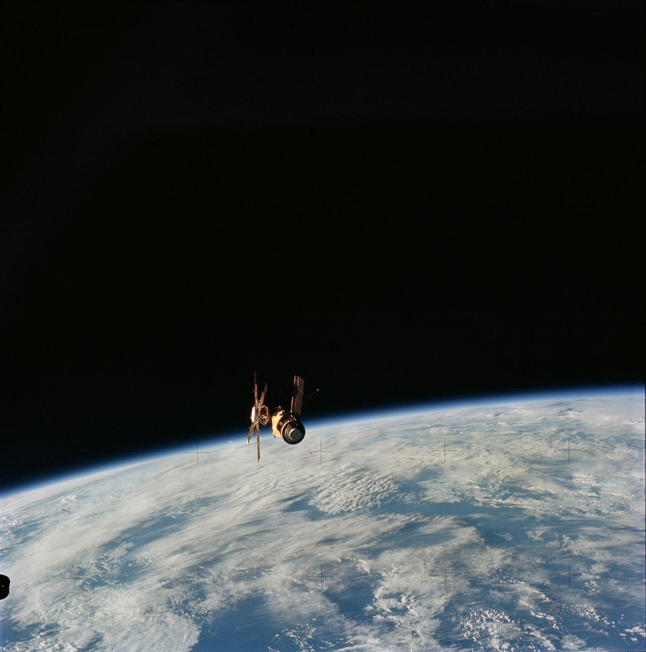
SL4-143-4707 (8 Feb. 1974) --- An overhead view of the Skylab space station cluster in Earth orbit as photographed from the Skylab 4 Command and Service Modules (CSM) during the final fly-around by the CSM before returning home. The space station is contrasted against a cloud-covered Earth. Note the solar shield which was deployed by the second crew of Skylab and from which a micrometeoroid shield has been missing since the cluster was launched on May 14, 1973. The OWS solar panel on the left side was also lost on workshop launch day. Photo credit: NASA
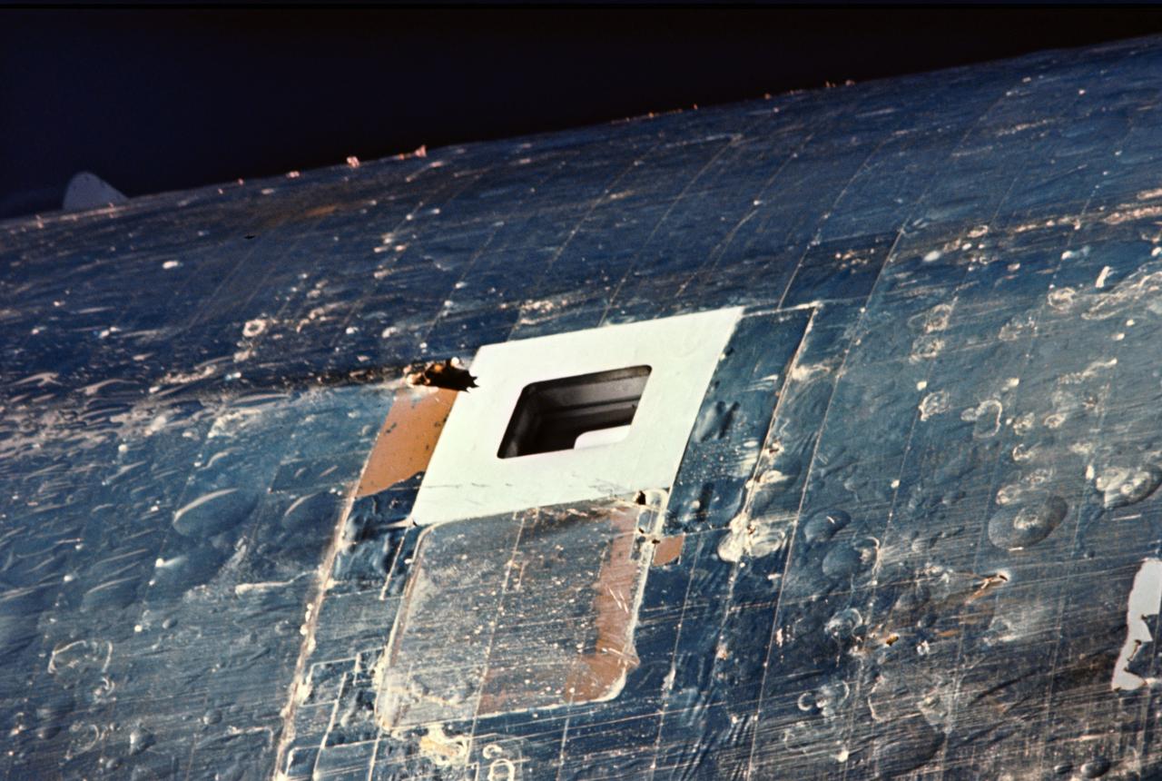
This close up view of one of the two scientific airlocks on the Skylab Orbital Workshop Section was taken from the Skylab 2 Command/Service Module during its initial fly around inspection. The micrometeoroid shield can be seen to be missing from this section of the orbital workshop. A parasol solar shield was later devised and put in place over this damaged area through this very same airlock opening.
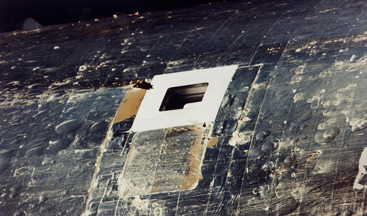
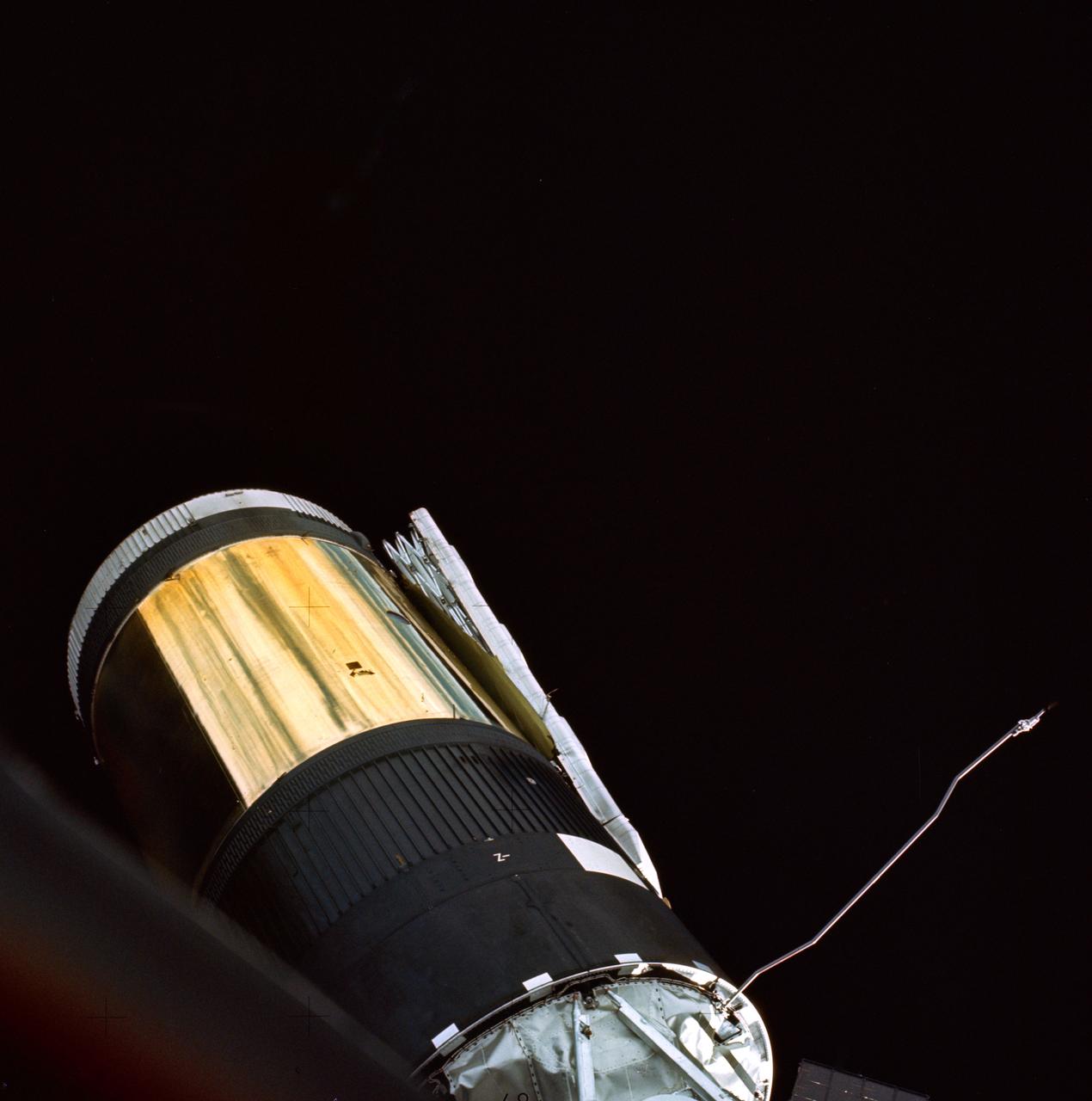
The Saturn V vehicle, carrying the unmarned orbital workshop for the Skylab-1 mission, lifted off successfully and all systems performed normally. Sixty-three seconds into flight, engineers in the operation support and control center saw an unexpected telemetry indication that signalled that damages occurred on one solar array and the micrometeoroid shield during the launch. The micrometeoroid shield, a thin protective cylinder surrounding the workshop protecting it from tiny space particles and the sun's scorching heat, ripped loose from its position around the workshop. This caused the loss of one solar wing and jammed the other. Still unoccupied, the Skylab was stricken with the loss of the heat shield and sunlight beat mercilessly on the lab's sensitive skin. Internal temperatures soared, rendering the the station uninhabitable, threatening foods, medicines, films, and experiments. This image shows the sun-ravaged skin of the Orbital Workshop, bared by the missing heat shield, with blister scars and tarnish from temperatures that reached 300 degrees F. The rectangular opening at the upper center is the scientific airlock through which the parasol to protect the workshop from sun's rays was later deployed. This view was taken during a fly-around inspection by the Skylab-2 crew. The Marshall Space Flight Center had a major role in developing the procedures to repair the damaged Skylab.
The Saturn V vehicle, carrying the unmarned orbital workshop for the Skylab-1 mission, lifted off successfully and all systems performed normally. Sixty-three seconds into the flight, engineers in the operation support and control center saw an unexpected telemetry indication that signalled that damages occurred on one solar array and the micrometeoroid shield during the launch. The micrometeoroid shield, a thin protective cylinder surrounding the workshop protecting it from tiny space particles and the sun's scorching heat, ripped loose from its position around the workshop. This caused the loss of one solar wing and jammed the other. Still unoccupied, the Skylab was stricken with the loss of the heat shield and sunlight beat mercilessly on the lab's sensitive skin. Internal temperatures soared, rendering the station uninhabitable, threatening foods, medicines, films, and experiments. This image, taken during a fly-around inspection by the Skylab-2 crew, shows the station's remaining solar panel jammed against its side. The Marshall Space Flight Center had a major role in developing the procedures to repair the damaged Skylab.
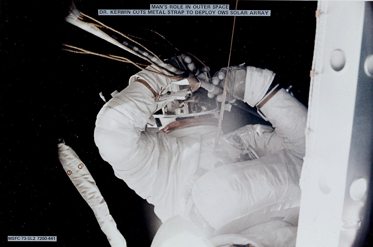
The Saturn V vehicle, carrying the unmarned orbital workshop for the Skylab-1 mission, lifted off successfully and all systems performed normally. Sixty-three seconds into the flight, engineers in the operation support and control center saw an unexpected telemetry indication that signalled that damages occurred on one solar array and the micrometeoroid shield during the launch. The micrometeoroid shield, a thin protective cylinder surrounding the workshop protecting it from tiny space particles and the sun's scorching heat, ripped loose from its position around the workshop. This caused the loss of one solar wing and jammed the other. Still unoccupied, the Skylab was stricken with the loss of the heat shield and sunlight beat mercilessly on the lab's sensitive skin. Intrnal temperatures soared, rendering the station uninhabitable, threatening foods, medicines, films, and experiments. This image shows astronaut Kerwin cutting the metal strap to free and deploy the Orbital Workshop solar array. Kerwin used special cutting tools developed by engineers at the Marshall Space Flight Center (MSFC). The MSFC had a major role in developing the procedures to repair the damaged Skylab.
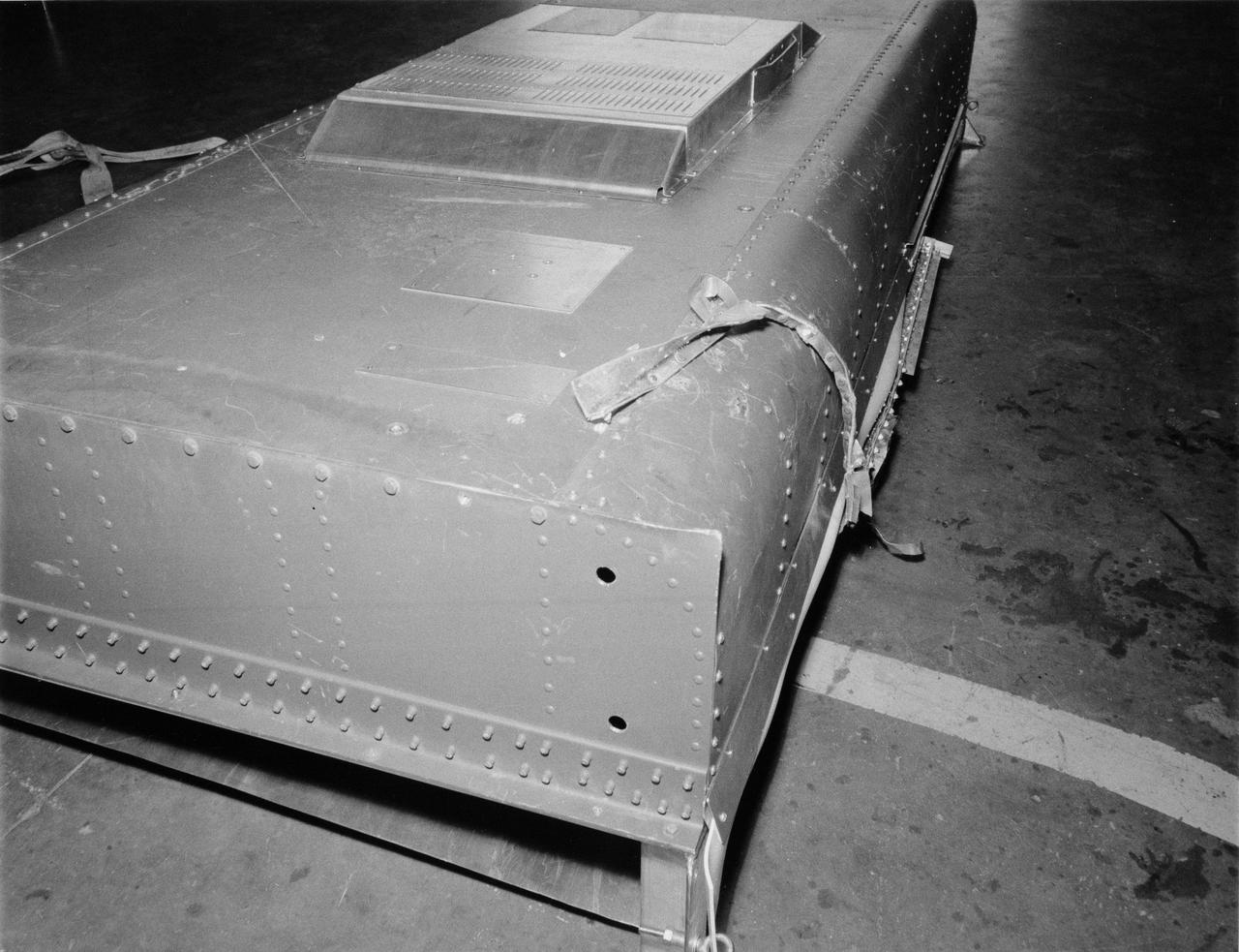
S73-27406 (5 June 1973) --- This structure duplicates the current problem with solar array wing number one on Skylab. The wing is being held against the side of the Orbital Workshop by what appears to be a strip of metal from the Meteoroid shield. Photo credit: NASA
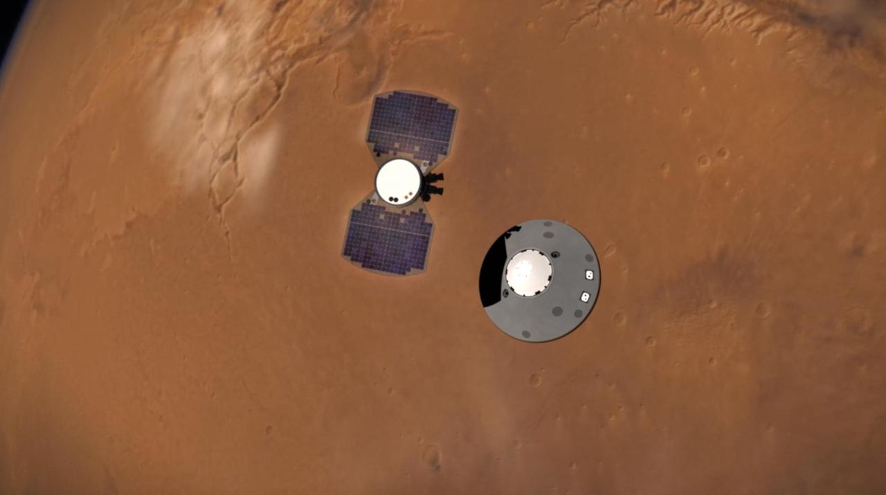
This illustration shows NASA's InSight lander separating from its cruise stage as it prepares to enter Mars' atmosphere. The InSight lander is on the right, tucked inside a protective heat shield and back shell. The cruise stage with solar panels is on the left. https://photojournal.jpl.nasa.gov/catalog/PIA22828
iss066e166325 (March 15, 2022) --- NASA astronaut Kayla Barron points the camera toward herself with her spaceuit's helmet shield down and takes a "space-selfie" during a six-hour and 54-minute spacewalk to set up the orbital lab for its next roll-out solar array.
SL2-4-265 (25 May 1973) --- Skylab 2, approach to Skylab at long range, fly-around inspection. Orbital Workshop with area of missing micrometeoroid shield visible and partially deployed solar array visible. Photo credit: NASA
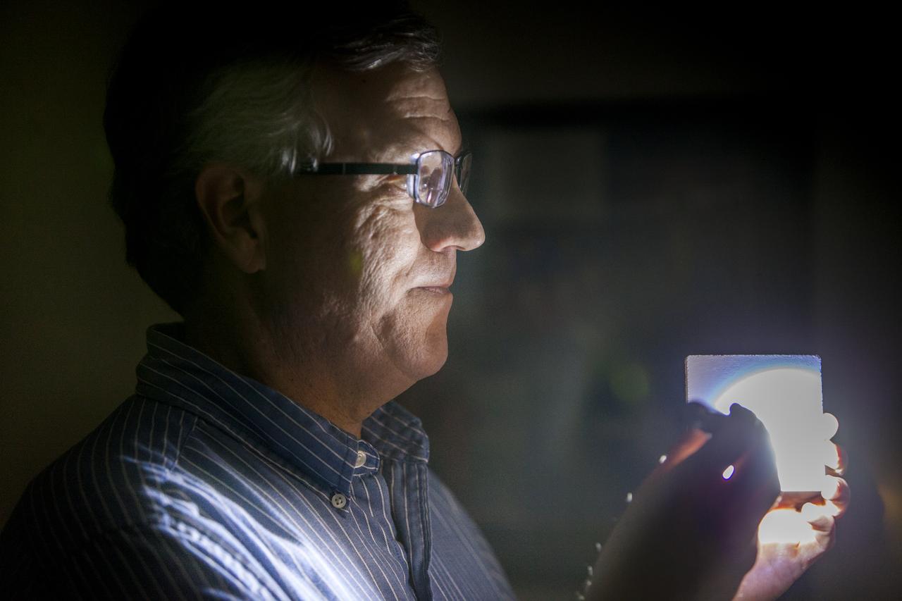
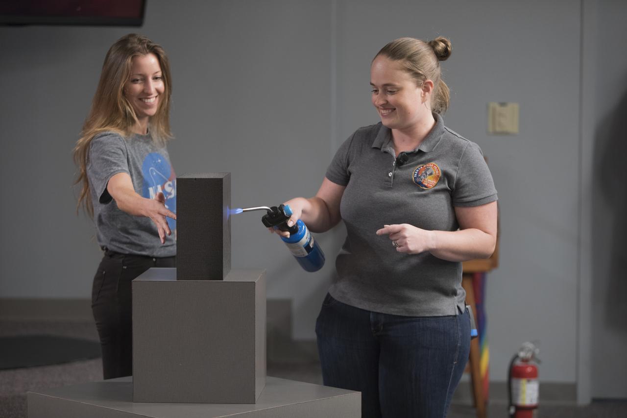
Robert Youngquist, Ph.D., tests a sample disk with a "Solar White" cryogenic selective surface coating with a flash light, demonstrating the coating’s reflective properties. The innovative coating is predicted to reflect more than 99.9 percent of the simulated solar infrared radiation. This technology could enable storing super-cold, or cryogenic, liquids and support systems that shield astronauts against radiation during the Journey to Mars.

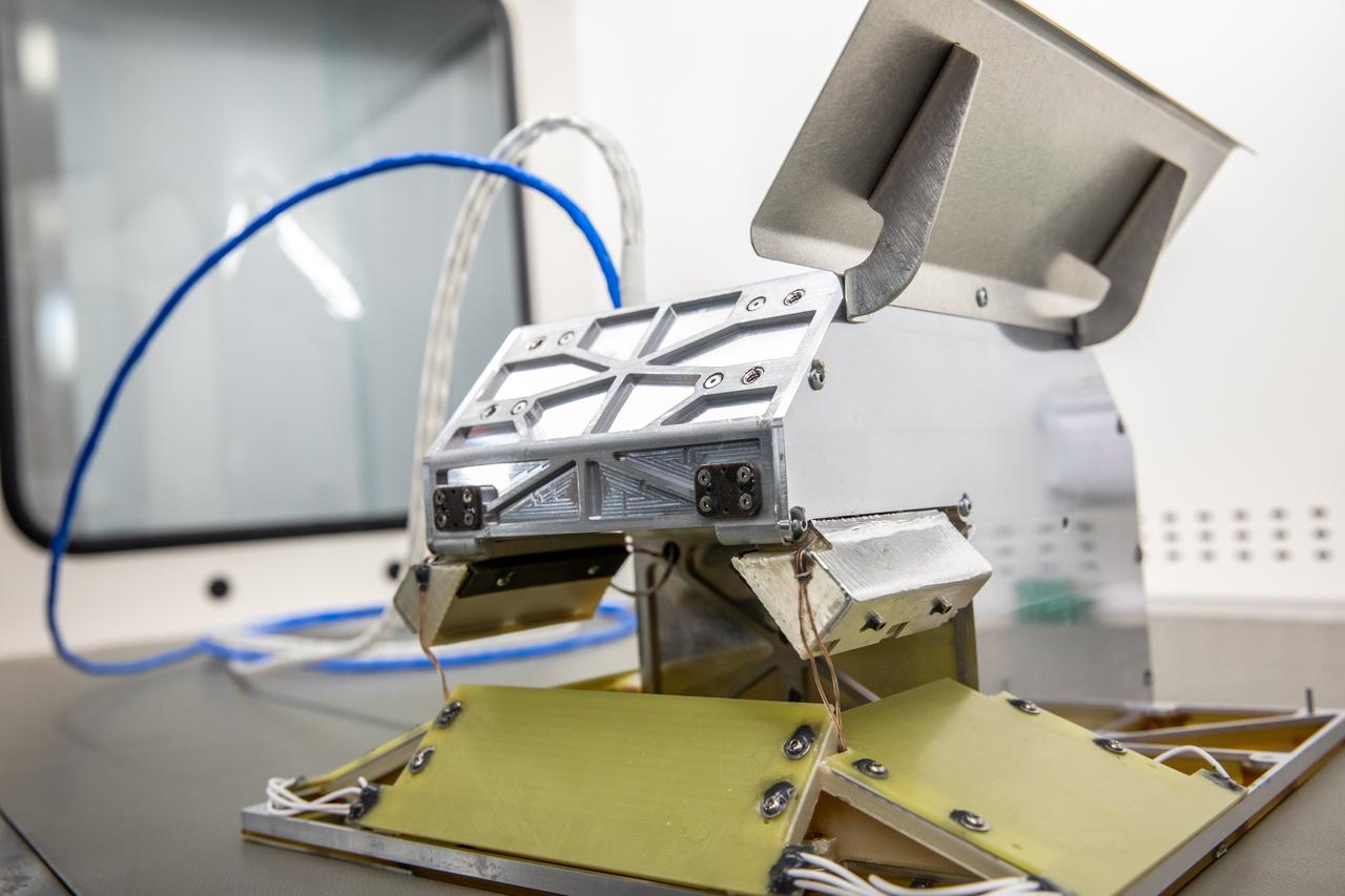
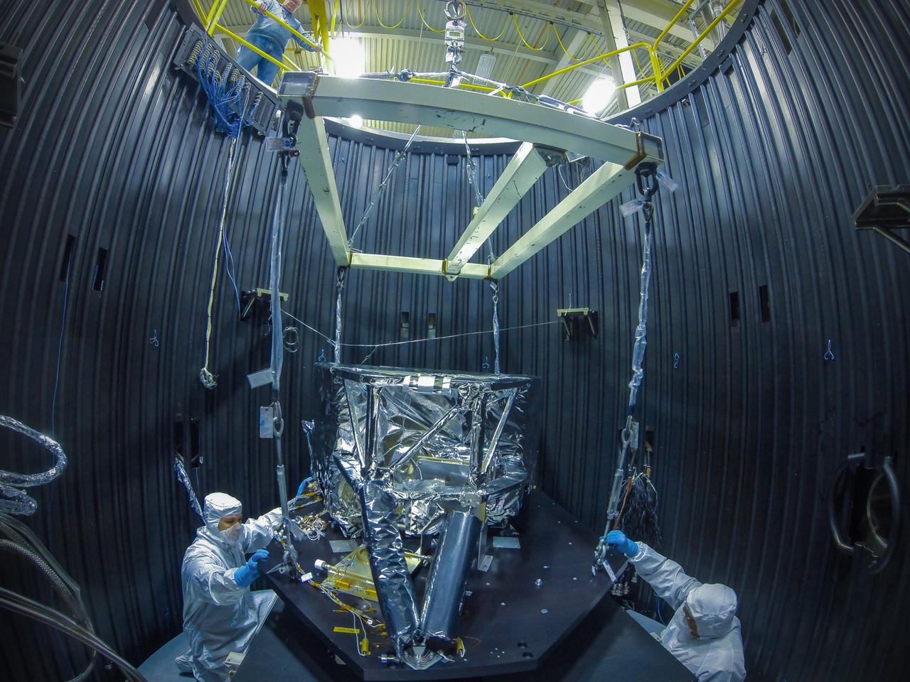
THE SOLAR PROBE PLUS CUP INSTRUMENT WILL BE PART OF THE SOLAR PROBE PLUS MISSION TO STUDY THE SUN. THE CUP WILL FLY ON THE SPACECRAFT ON THE OUTSIDE OF THE SHIELD AND WILL "CATCH" CHARGED PARTICLES FROM THE SUN AND ANALYZE THEM. A TEAM FROM THE HARVARD SMITHSONIAN ASTROPHYSICS OBSERVATORY IS BUILDING THIS INSTRUMENT AND TESTED AN ENGINEERING MODEL OF THE CUP IN AN ENVIRONMENTAL TEST FACILITY AT NASA'S MARSHALL SPACE FLIGHT CENTER.INSIDE THE VACUUM CHAMBER, THE PROBE WAS EXPOSED TO AN ENVIRONMENTAL CONDITIONS SIMILAR TO THOSE FOUND IN SPACE
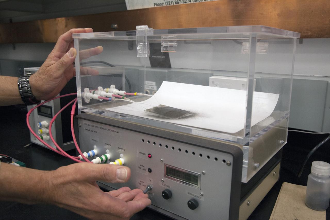
CAPE CANAVERAL, Fla. -- Dust particles are readied for an experiment for the Electrodynamic Dust Shield for Dust Mitigation project in the Electrostatics and Surface Physics Laboratory in the SwampWorks at NASA's Kennedy Space Center in Florida. The fabricated material is designed to mimic the dust on the lunar surface. The technology works by creating an electric field that propagates out like the ripples on a pond. This could prevent dust accumulation on spacesuits, thermal radiators, solar panels, optical instruments and view ports for future lunar and Mars exploration activities. CAPE CANAVERAL, Fla. -- Preparations are underway to conduct a dust particle experiment for the Electrodynamic Dust Shield for Dust Mitigation project in the Electrostatics and Surface Physics Laboratory in the SwampWorks at NASA's Kennedy Space Center in Florida. The technology works by creating an electric field that propagates out like the ripples on a pond. This could prevent dust accumulation on spacesuits, thermal radiators, solar panels, optical instruments and view ports for future lunar and Mars exploration activities.
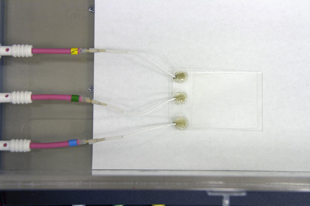
CAPE CANAVERAL, Fla. -- Preparations are underway to conduct a dust particle experiment for the Electrodynamic Dust Shield for Dust Mitigation project in the Electrostatics and Surface Physics Laboratory in the SwampWorks at NASA's Kennedy Space Center in Florida. The technology works by creating an electric field that propagates out like the ripples on a pond. This could prevent dust accumulation on spacesuits, thermal radiators, solar panels, optical instruments and view ports for future lunar and Mars exploration activities. CAPE CANAVERAL, Fla. -- Preparations are underway to conduct a dust particle experiment for the Electrodynamic Dust Shield for Dust Mitigation project in the Electrostatics and Surface Physics Laboratory in the SwampWorks at NASA's Kennedy Space Center in Florida. The technology works by creating an electric field that propagates out like the ripples on a pond. This could prevent dust accumulation on spacesuits, thermal radiators, solar panels, optical instruments and view ports for future lunar and Mars exploration activities.
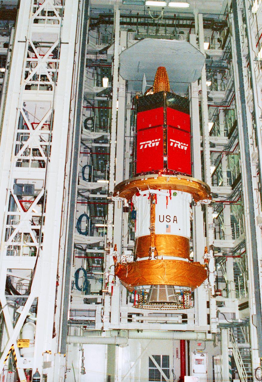
STS-43 Tracking and Data Relay Satellite E (TDRS-E) undergoes preflight processing in the Kennedy Space Center's (KSC's) Vertical Processing Facility (VPF) before being loaded into a payload canister for transfer to the launch pad and eventually into Atlantis', Orbiter Vehicle (OV) 104's, payload bay (PLB). This side of the TDRS-E will rest at the bottom of the PLB therefore the airborne support equipment (ASE) forward frame keel pin (at center of spacecraft) and the umbilical boom running between the two ASE frames are visible. The solar array panels are covered with protective TRW shields. Above the shields the stowed antenna and solar sail are visible. The inertial upper stage (IUS) booster is the white portion of the spacecraft and rests in the ASE forward frame and ASE aft frame tilt actuator (AFTA) frame (at the bottom of the IUS). The IUS booster nozzle extends beyond the AFTA frame. View provided by KSC with alternate number KSC-91PC-1079.
SL4-143-4706 (8 Feb. 1974) --- An overhead view of the Skylab space station cluster in Earth orbit as photographed from the Skylab 4 Command and Service Modules (CSM) during the final fly-around by the CSM before returning home. The space station is contrasted against a cloud-covered Earth. Note the solar shield which was deployed by the second crew of Skylab and from which a micro meteoroid shield has been missing since the cluster was launched on May 14, 1973. The Orbital Workshop (OWS) solar panel on the left side was also lost on workshop launch day. Inside the Command Module (CM) when this picture was made were astronaut Gerald P. Carr, commander; scientist-astronaut Edward G. Gibson, science pilot; and astronaut William R. Pogue, pilot. The crew used a 70mm hand-held Hasselblad camera to take this photograph. Photo credit: NASA
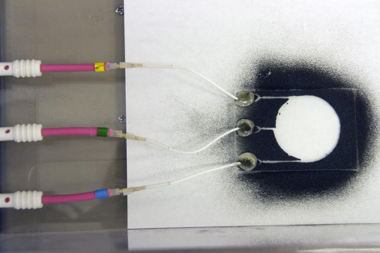
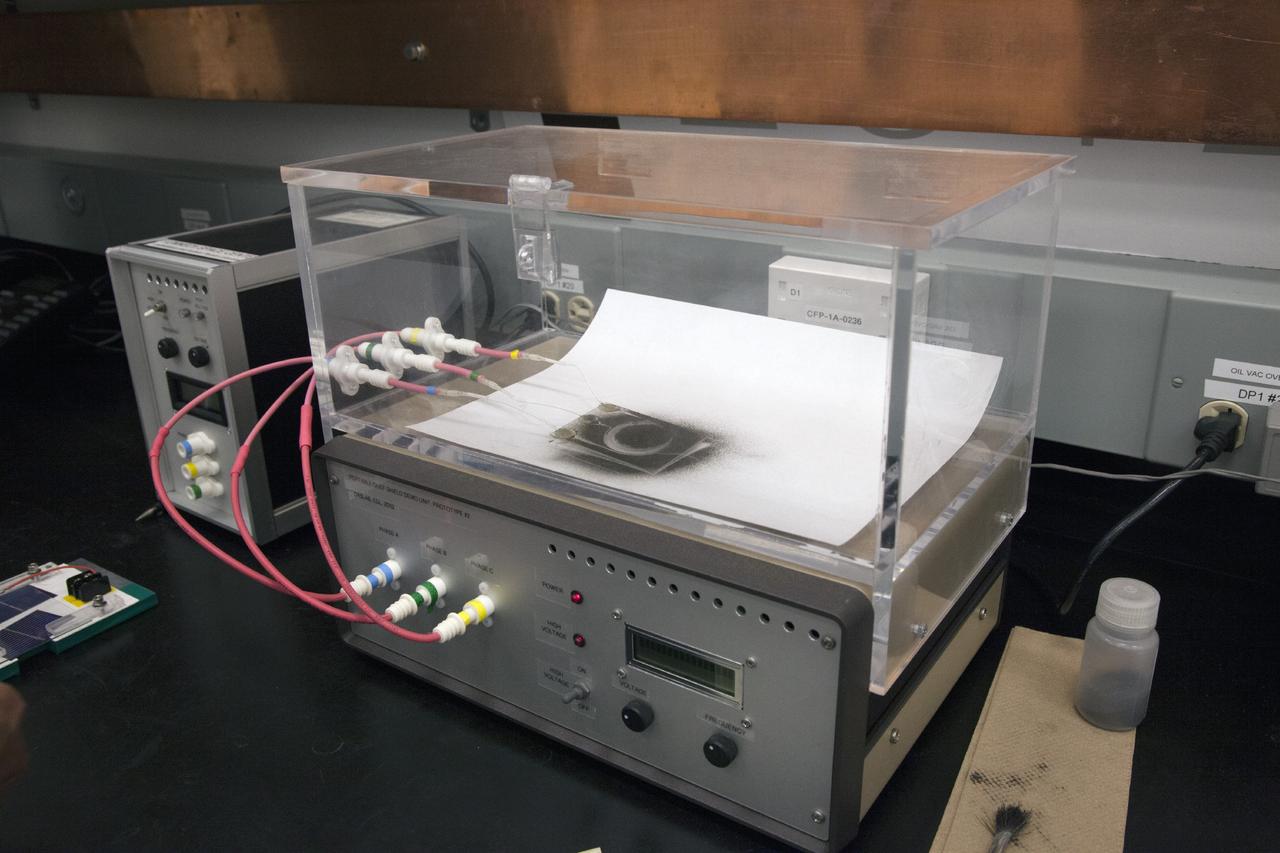
CAPE CANAVERAL, Fla. -- Dust particles scatter during an experiment for the Electrodynamic Dust Shield for Dust Mitigation project in the Electrostatics and Surface Physics Laboratory in the SwampWorks at NASA's Kennedy Space Center in Florida. The fabricated material is designed to mimic the dust on the lunar surface. The technology works by creating an electric field that propagates out like the ripples on a pond. This could prevent dust accumulation on spacesuits, thermal radiators, solar panels, optical instruments and view ports for future lunar and Mars exploration activities. CAPE CANAVERAL, Fla. -- Preparations are underway to conduct a dust particle experiment for the Electrodynamic Dust Shield for Dust Mitigation project in the Electrostatics and Surface Physics Laboratory in the SwampWorks at NASA's Kennedy Space Center in Florida. The technology works by creating an electric field that propagates out like the ripples on a pond. This could prevent dust accumulation on spacesuits, thermal radiators, solar panels, optical instruments and view ports for future lunar and Mars exploration activities.
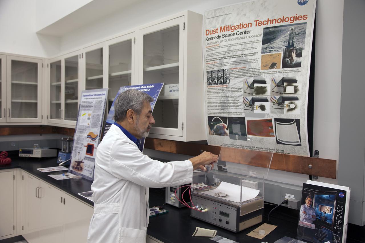
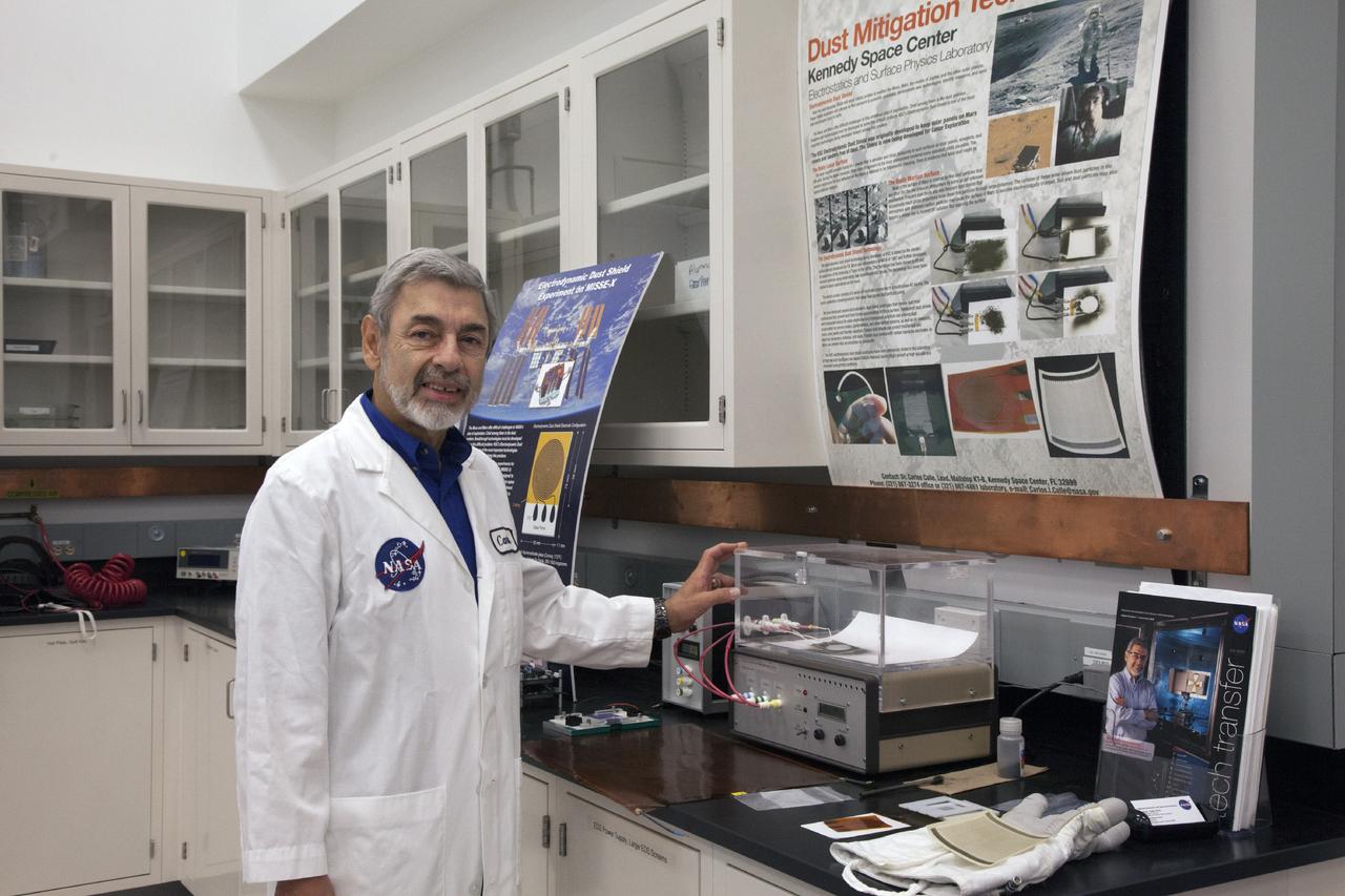
CAPE CANAVERAL, Fla. -- Dr. Carlos Calle, senior research scientist on the Electrodynamic Dust Shield for Dust Mitigation project, demonstrates equipment used in his experiments in the Electrostatics and Surface Physics Laboratory in the SwampWorks at NASA's Kennedy Space Center in Florida. Electrodynamic dust shield, or EDS, technology is based on concepts originally developed by NASA as early as 1967 and later by the University of Tokyo. In 2003, NASA, in collaboration with the University of Arkansas at Little Rock, started development of the EDS for dust particle removal from solar panels to be used on future missions to the moon, an asteroid or Mars. A flight experiment to expose the dust shields to the space environment currently is under development. For more information, visit: http://www.nasa.gov/content/scientists-developing-ways-to-mitigate-dust-problem-for-explorers/ Photo credit: NASA/Dan Casper
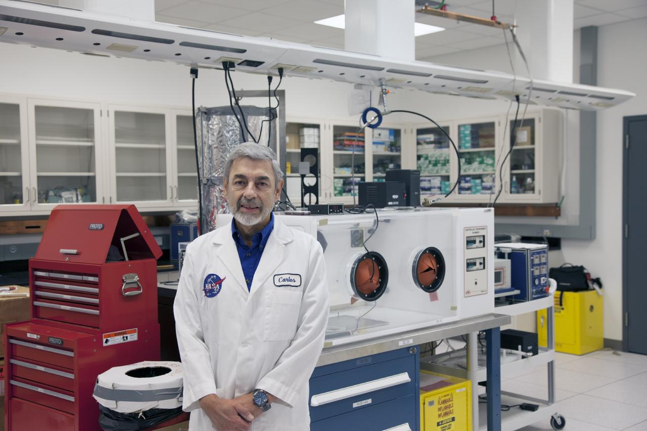
CAPE CANAVERAL, Fla. -- Dr. Carlos Calle, senior research scientist on the Electrodynamic Dust Shield for Dust Mitigation project, manages the Electrostatics and Surface Physics Laboratory in the SwampWorks at NASA's Kennedy Space Center in Florida. Electrodynamic dust shield, or EDS, technology is based on concepts originally developed by NASA as early as 1967 and later by the University of Tokyo. In 2003, NASA, in collaboration with the University of Arkansas at Little Rock, started development of the EDS for dust particle removal from solar panels to be used on future missions to the moon, an asteroid or Mars. A flight experiment to expose the dust shields to the space environment currently is under development. For more information, visit: http://www.nasa.gov/content/scientists-developing-ways-to-mitigate-dust-problem-for-explorers/ Photo credit: NASA/Dan Casper
NASA's InSight spacecraft, its heat shield and its parachute were imaged on Dec. 6 and 11 by the HiRISE camera onboard NASA's Mars Reconnaissance Orbiter. In images released today, the three new features on the Martian landscape appear teal. That's not their actual color: Light reflected off their surfaces cause the color to be saturated. The ground around the lander is dark, blasted by its retrorockets during descent. Look carefully for a butterfly shape, and you can make out the lander's solar panels on either side. Unannotated, individual images of the lander, heat shield and parachute are also available. https://photojournal.jpl.nasa.gov/catalog/PIA22875
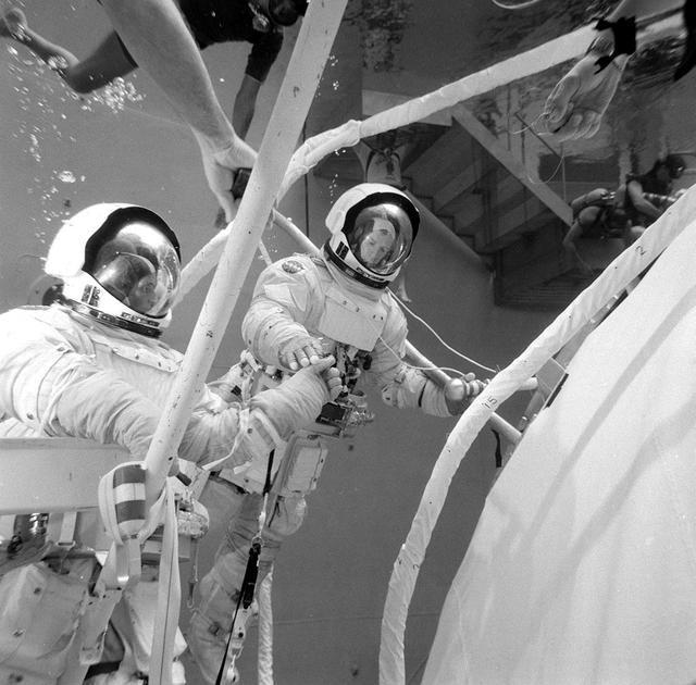
This photograph was taken during testing of an emergency procedure to free jammed solar array panels on the Skylab workshop. A metal strap became tangled over one of the folded solar array panels when Skylab lost its micrometeoroid shield during the launch. This photograph shows astronauts Schweickart and Gibson in the Marshall Space Flight Center (MSFC) Neutral Buoyancy Simulator (NBS) using various cutting tools and methods developed by the MSFC to free the jammed solar wing. Extensive testing and many hours of practice in simulators such as the NBS tank helped prepare the Skylab crewmen for extravehicular performance in the weightless environment. This huge water tank simulated the weightless environment that the astronauts would encounter in space.
CAPE CANAVERAL, Fla. -- Dr. Carlos Calle, senior research scientist on the Electrodynamic Dust Shield for Dust Mitigation project, demonstrates a dust particle experiment in the Electrostatics and Surface Physics Laboratory in the SwampWorks at NASA's Kennedy Space Center in Florida. The technology works by creating an electric field that propagates out like the ripples on a pond. This could prevent dust accumulation on spacesuits, thermal radiators, solar panels, optical instruments and view ports for future lunar and Mars exploration activities. Electrodynamic dust shield, or EDS, technology is based on concepts originally developed by NASA as early as 1967 and later by the University of Tokyo. In 2003, NASA, in collaboration with the University of Arkansas at Little Rock, started development of the EDS for dust particle removal from solar panels to be used on future missions to the moon, an asteroid or Mars. A flight experiment to expose the dust shields to the space environment currently is under development. For more information, visit: http://www.nasa.gov/content/scientists-developing-ways-to-mitigate-dust-problem-for-explorers/ Photo credit: NASA/Dan Casper
CAPE CANAVERAL, Fla. -- Dust particle experiments are conducted for Electrodynamic Dust Shield for Dust Mitigation project in the Electrostatics and Surface Physics Laboratory in the SwampWorks at NASA's Kennedy Space Center in Florida. The technology works by creating an electric field that propagates out like the ripples on a pond. This could prevent dust accumulation on spacesuits, thermal radiators, solar panels, optical instruments and view ports for future lunar and Mars exploration activities. Electrodynamic dust shield, or EDS, technology is based on concepts originally developed by NASA as early as 1967 and later by the University of Tokyo. In 2003, NASA, in collaboration with the University of Arkansas at Little Rock, started development of the EDS for dust particle removal from solar panels to be used on future missions to the moon, an asteroid or Mars. A flight experiment to expose the dust shields to the space environment currently is under development. For more information, visit: http://www.nasa.gov/content/scientists-developing-ways-to-mitigate-dust-problem-for-explorers/ Photo credit: NASA/Dan Casper
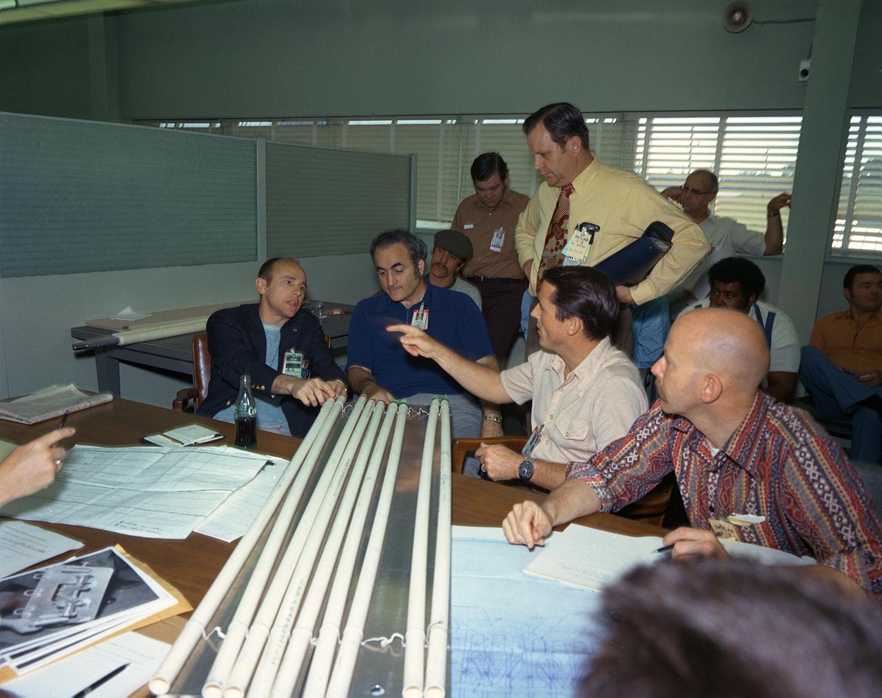
Sixty-three seconds after the launch of the modified Saturn V vehicle carrying the Skylab cluster, engineers in the operation support and control center saw an unexpected telemetry indication that signalled that damages occurred on one solar array and the micrometeoroid shield during the launch. Still unoccupied, the Skylab was stricken with the loss of the heat shield and sunlight beat mercilessly on the lab's sensitive skin. Internal temperatures soared, rendering the the station uninhabitable, threatening foods, medicines, films, and experiments. The launch of the first marned Skylab (Skylab-2) mission was delayed until methods were devised to repair and salvage the workshop. Personnel from other NASA Centers and industries quickly joined the Marshall Space Flight Center (MSFC) in efforts to save the damaged Skylab. They worked day and night for the next several days. Eventually the MSFC developed, tested, rehearsed, and approved three repair options. These options included a parasol sunshade and a twin-pole sunshade to restore the temperature inside the workshop, and a set of metal cutting tools to free the jammed solar panel. This photograph was taken during a discussion of the methods of the twin-pole Sun shield by (left to right) Astronaut Alan Bean, MSFC Director Dr. Rocco Petrone, Astronaut Edward Gibson, and MSFC engineer Richard Heckman. Dr. William Lucas, who became MSFC Director after Dr. Petrone left MSFC in March of 1974, is standing.
CAPE CANAVERAL, Fla. -- Dr. Carlos Calle, senior research scientist on the Electrodynamic Dust Shield for Dust Mitigation project, demonstrates a dust particle experiment in the Electrostatics and Surface Physics Laboratory in the SwampWorks at NASA's Kennedy Space Center in Florida. The technology works by creating an electric field that propagates out like the ripples on a pond. This could prevent dust accumulation on spacesuits, thermal radiators, solar panels, optical instruments and view ports for future lunar and Mars exploration activities. Electrodynamic dust shield, or EDS, technology is based on concepts originally developed by NASA as early as 1967 and later by the University of Tokyo. In 2003, NASA, in collaboration with the University of Arkansas at Little Rock, started development of the EDS for dust particle removal from solar panels to be used on future missions to the moon, an asteroid or Mars. A flight experiment to expose the dust shields to the space environment currently is under development. For more information, visit: http://www.nasa.gov/content/scientists-developing-ways-to-mitigate-dust-problem-for-explorers/ Photo credit: NASA/Dan Casper
CAPE CANAVERAL, Fla. -- Dr. Carlos Calle, senior research scientist on the Electrodynamic Dust Shield for Dust Mitigation project, works with dust fabricated for use in his experiments in the Electrostatics and Surface Physics Laboratory in the SwampWorks at NASA's Kennedy Space Center in Florida. The fabricated material is designed to mimic the dust on the lunar surface. The technology works by creating an electric field that propagates out like the ripples on a pond. This could prevent dust accumulation on spacesuits, thermal radiators, solar panels, optical instruments and view ports for future lunar and Mars exploration activities. Electrodynamic dust shield, or EDS, technology is based on concepts originally developed by NASA as early as 1967 and later by the University of Tokyo. In 2003, NASA, in collaboration with the University of Arkansas at Little Rock, started development of the EDS for dust particle removal from solar panels to be used on future missions to the moon, an asteroid or Mars. A flight experiment to expose the dust shields to the space environment currently is under development. For more information, visit: http://www.nasa.gov/content/scientists-developing-ways-to-mitigate-dust-problem-for-explorers/ Photo credit: NASA/Dan Casper
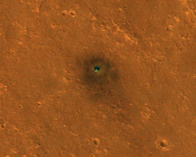
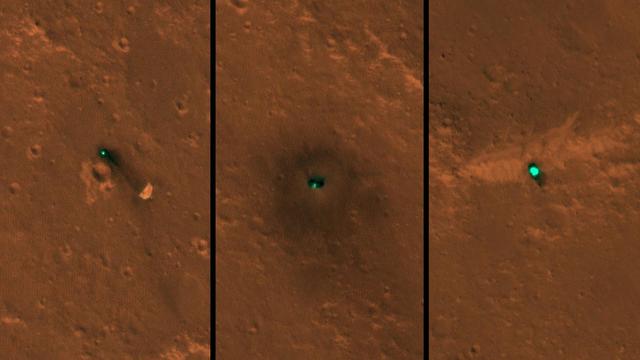
NASA's InSight spacecraft and its recently deployed Wind and Thermal Shield were imaged on Mars on Feb. 4, 2019, by the HiRISE camera aboard NASA's Mars Reconnaissance Orbiter. On Feb. 2, 2019, InSight's robotic arm placed the special shield over its seismometer on the Martian surface to protect the instrument from wind and extreme temperatures. The green object in this image is the InSight lander; the white dot just below it is the shield, which is especially bright and reflective. The shield is a little less than 6 feet (1.8 meters) away from the lander. The dark circles on either side of the lander are its solar panels. The total width of the lander with both panels open is 19 feet, 8 inches (6 meters). The image also shows the darkened ground where InSight's retrorockets blew away lighter-colored dust as the lander touched down on Nov. 26, 2018. Scientists are interested in imaging this location over time to watch how quickly the lighter-colored Martian dust covers that darkened surface. https://photojournal.jpl.nasa.gov/catalog/PIA23043
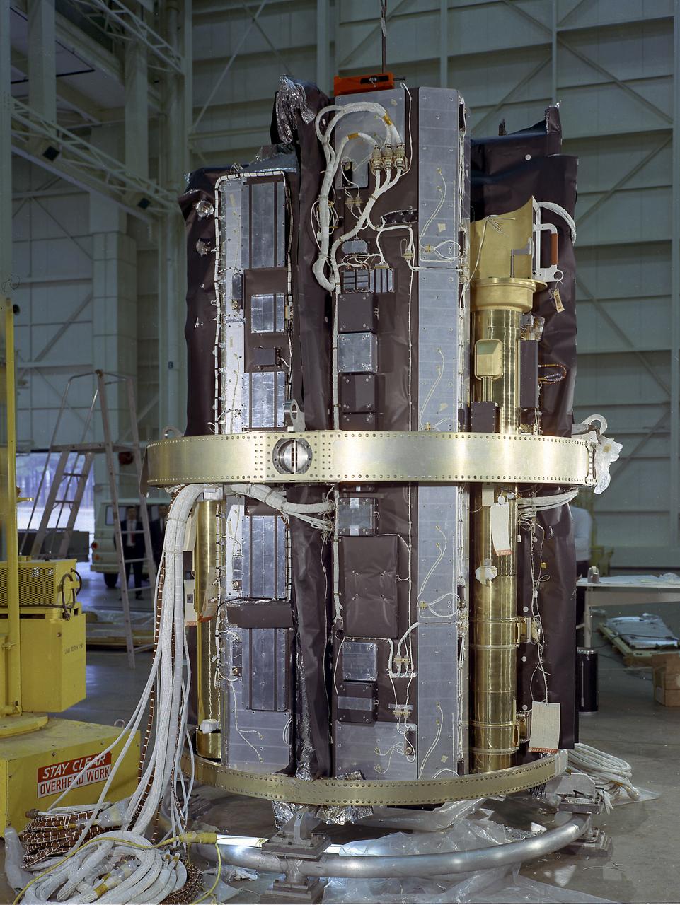
The Apollo Telescope Mount (ATM), designed and developed by the Marshall Space Flight Center, served as the primary scientific instrument unit aboard the Skylab. The ATM contained eight complex astronomical instruments designed to observe the Sun over a wide spectrum from visible light to x-rays. This image shows the ATM spar assembly. All solar telescopes, the fine Sun sensors, and some auxiliary systems are mounted on the spar, a cruciform lightweight perforated metal mounting panel that divides the 10-foot long canister lengthwise into four equal compartments. The spar assembly was nested inside a cylindrical canister that fit into the rack, a complex frame, and was protected by the solar shield.
The Apollo Telescope Mount (ATM), designed and developed by the Marshall Space Flight Center, served as the primary scientific instrument unit aboard the Skylab. The ATM contained eight complex astronomical instruments designed to observe the Sun over a wide spectrum from visible light to x-rays. This image shows the ATM spar assembly. All solar telescopes, the fine Sun sensors, and some auxiliary systems are mounted on the spar, a cruciform lightweight perforated metal mounting panel that divides the 10-foot long canister lengthwise into four equal compartments. The spar assembly was nested inside a cylindrical canister that fit into the rack, a complex frame, and was protected by the solar shield.

SL3-122-2609 (6 Aug. 1973) --- Scientist-astronaut Owen K. Garriott, Skylab 3 science pilot, looks at the camera as he participates in the Aug. 6, 1973 extravehicular activity (EVA) during which he and astronaut Jack R. Lousma, pilot, deployed the twin pole solar shield to help shade the Orbital Workshop (OWS). Photo credit: NASA
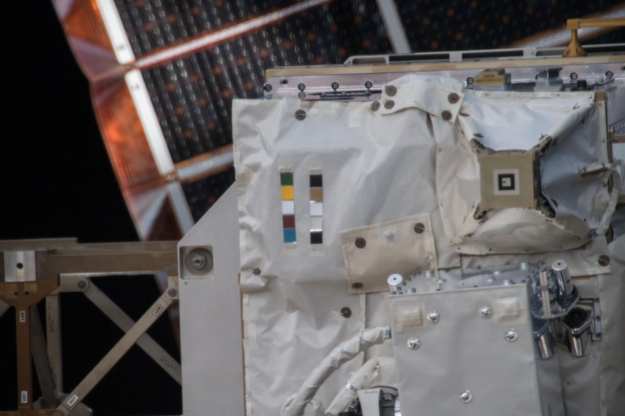
iss054e004111 (Dec. 26, 2017) --- Space Test Program - Houston 5 - Innovative Coatings Experiment (STP-H5-ICE) with International Space Station (ISS) solar panels in the background. A spacecraft’s exterior coating protects against extreme temperatures, shields the spacecraft from radiation, prevents contamination, and guides cameras that help robots or humans capture and service the spacecraft. STP-H5-ICE studies different paints and coatings that protext spacecraft exteriors.
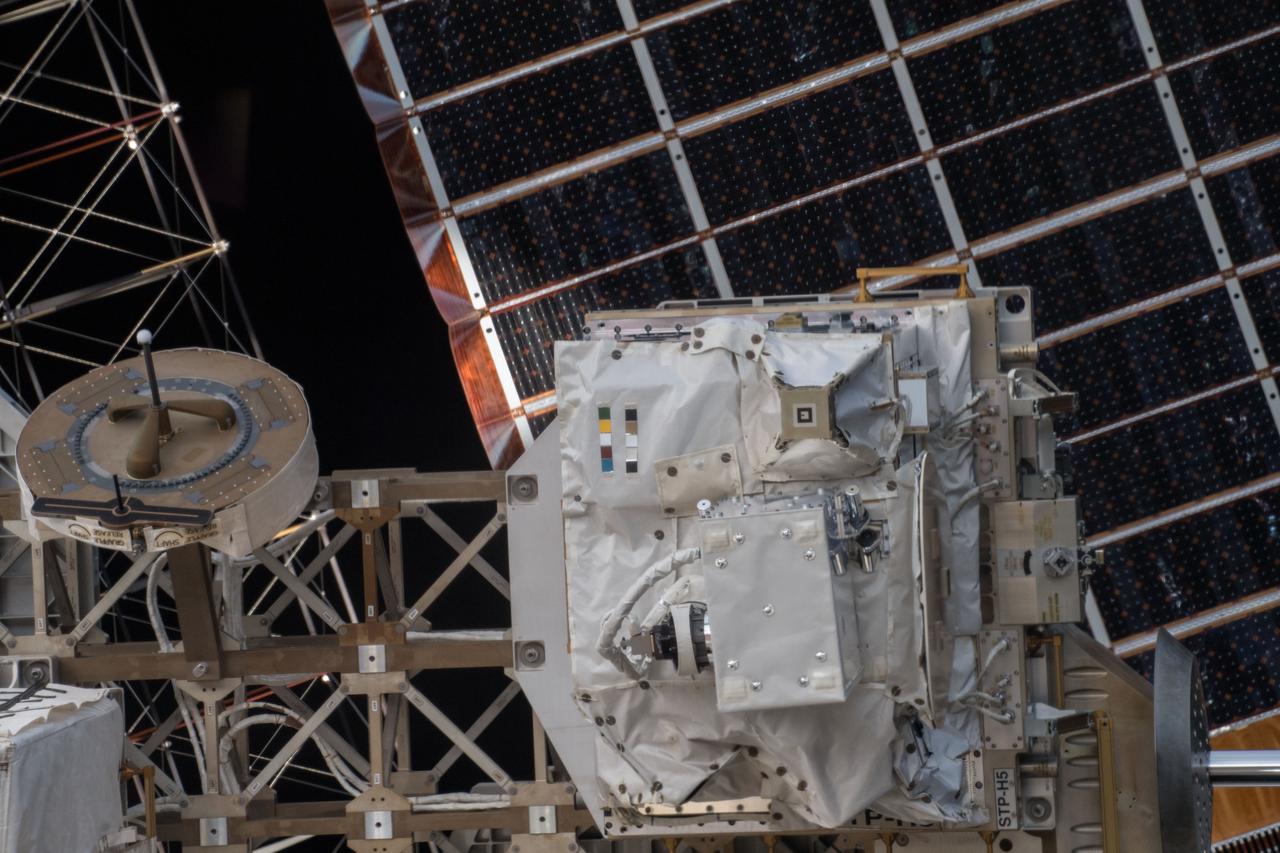
iss054e004105 (Dec. 26, 2017) --- Space Test Program - Houston 5 - Innovative Coatings Experiment (STP-H5-ICE) in front of International Space Station (ISS) solar panels. A spacecraft’s exterior coating protects against extreme temperatures, shields the spacecraft from radiation, prevents contamination, and guides cameras that help robots or humans capture and service the spacecraft. STP-H5-ICE studies different paints and coatings that protect spacecraft exteriors.

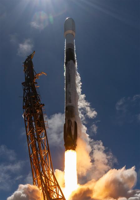
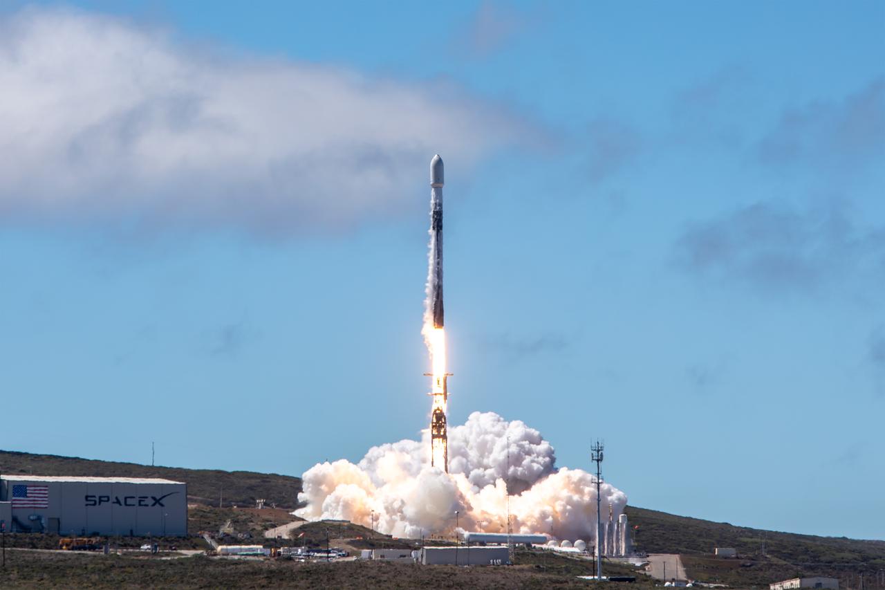
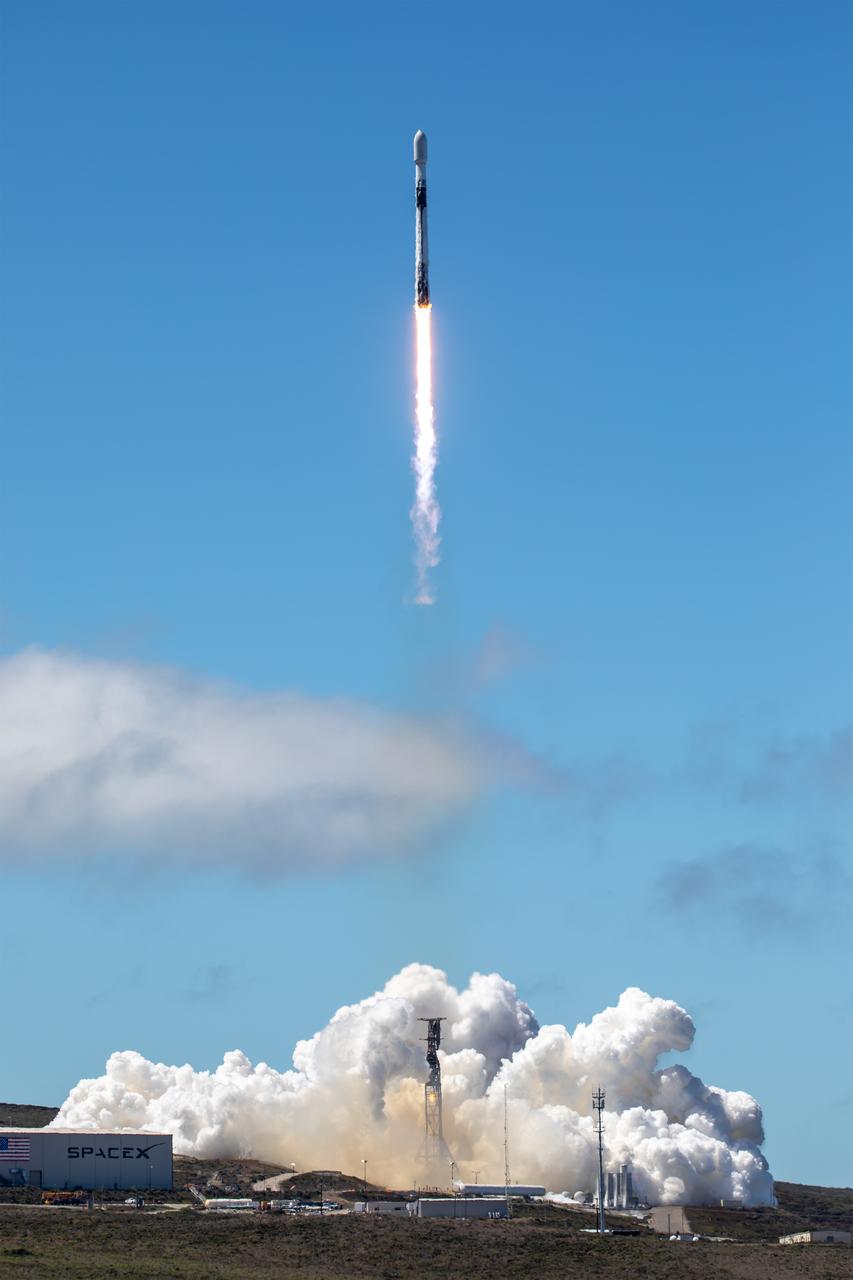
NASA’s TRACERS (Tandem Reconnection and Cusp Electrodynamics Reconnaissance Satellites) mission launches at 11:13 a.m. PDT (2:13 p.m. EDT) on Wednesday, July 23, 2025, atop a SpaceX Falcon 9 rocket at Space Launch Complex 4 East at Vandenberg Space Force Base in California. The TRACERS mission will study magnetic reconnection around Earth — a process in which electrically charged plasmas exchange energy in the atmosphere — to understand how the Sun’s solar wind interacts with the magnetosphere, Earth’s protective magnetic shield.
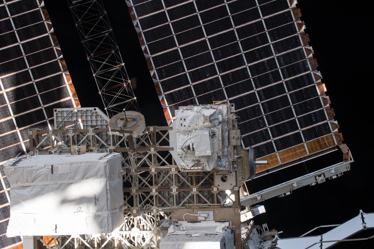
iss054e004101 (Dec. 26, 2017) --- Space Test Program - Houston 5 - Innovative Coatings Experiment (STP-H5-ICE) in front of International Space Station (ISS) solar panels. A spacecraft’s exterior coating protects against extreme temperatures, shields the spacecraft from radiation, prevents contamination, and guides cameras that help robots or humans capture and service the spacecraft. STP-H5-ICE studies different paints and coatings that protect spacecraft exteriors.
NASA’s TRACERS (Tandem Reconnection and Cusp Electrodynamics Reconnaissance Satellites) mission launches at 11:13 a.m. PDT (2:13 p.m. EDT) on Wednesday, July 23, 2025, atop a SpaceX Falcon 9 rocket at Space Launch Complex 4 East at Vandenberg Space Force Base in California. The TRACERS mission will study magnetic reconnection around Earth — a process in which electrically charged plasmas exchange energy in the atmosphere — to understand how the Sun’s solar wind interacts with the magnetosphere, Earth’s protective magnetic shield.

SL3-122-2610 (6 Aug. 1973) --- Scientist-astronaut Owen K. Garriott, Skylab 3 science pilot, looks at the camera as he participates in the Aug. 6, 1973 extravehicular activity (EVA) during which he and astronaut Jack R. Lousma, pilot, deployed the twin pole solar shield to help shade the Orbital Workshop (OWS). Photo credit: NASA
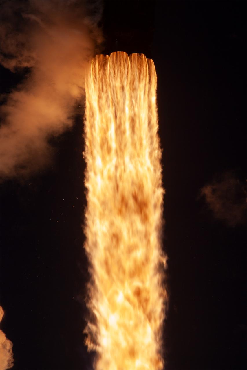
NASA’s TRACERS (Tandem Reconnection and Cusp Electrodynamics Reconnaissance Satellites) mission launches at 11:13 a.m. PDT (2:13 p.m. EDT) on Wednesday, July 23, 2025, atop a SpaceX Falcon 9 rocket at Space Launch Complex 4 East at Vandenberg Space Force Base in California. The TRACERS mission will study magnetic reconnection around Earth — a process in which electrically charged plasmas exchange energy in the atmosphere — to understand how the Sun’s solar wind interacts with the magnetosphere, Earth’s protective magnetic shield.
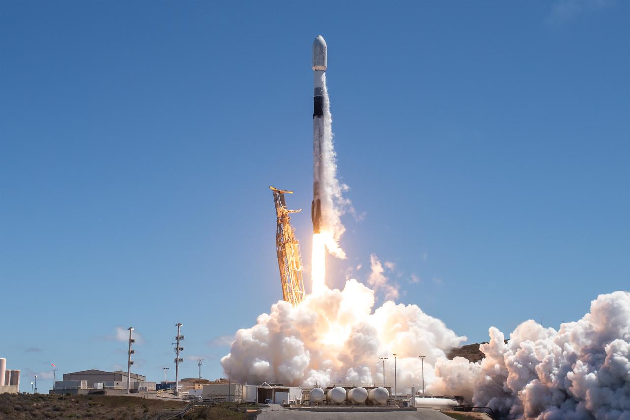
NASA’s TRACERS (Tandem Reconnection and Cusp Electrodynamics Reconnaissance Satellites) mission launches at 11:13 a.m. PDT (2:13 p.m. EDT) on Wednesday, July 23, 2025, atop a SpaceX Falcon 9 rocket at Space Launch Complex 4 East at Vandenberg Space Force Base in California. The TRACERS mission will study magnetic reconnection around Earth — a process in which electrically charged plasmas exchange energy in the atmosphere — to understand how the Sun’s solar wind interacts with the magnetosphere, Earth’s protective magnetic shield.
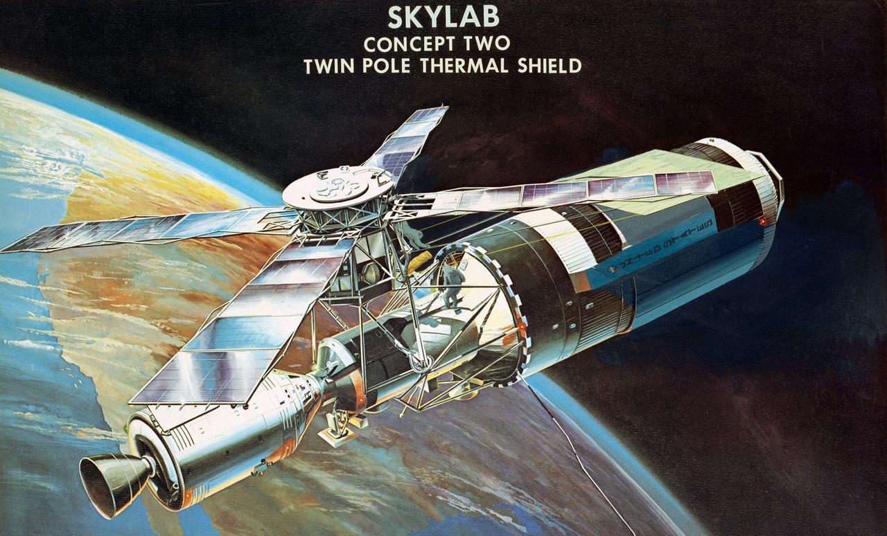
S73-26127 (1973) --- An artist's concept of the Skylab space station cluster in Earth orbit illustrating the deployment of the twin pole thermal shield to shade the Orbital Workshop (OWS) from the sun. This is one of the sunshade possibilities considered to solve the problem of the overheated OWS. Here the two Skylab 2 astronauts have completely deployed the sunshade. Note the evidence of another Skylab problem - the solar panels on the OWS are not deployed as required. Photo credit: NASA

NASA’s TRACERS (Tandem Reconnection and Cusp Electrodynamics Reconnaissance Satellites) mission launches at 11:13 a.m. PDT (2:13 p.m. EDT) on Wednesday, July 23, 2025, atop a SpaceX Falcon 9 rocket at Space Launch Complex 4 East at Vandenberg Space Force Base in California. The TRACERS mission will study magnetic reconnection around Earth — a process in which electrically charged plasmas exchange energy in the atmosphere — to understand how the Sun’s solar wind interacts with the magnetosphere, Earth’s protective magnetic shield.
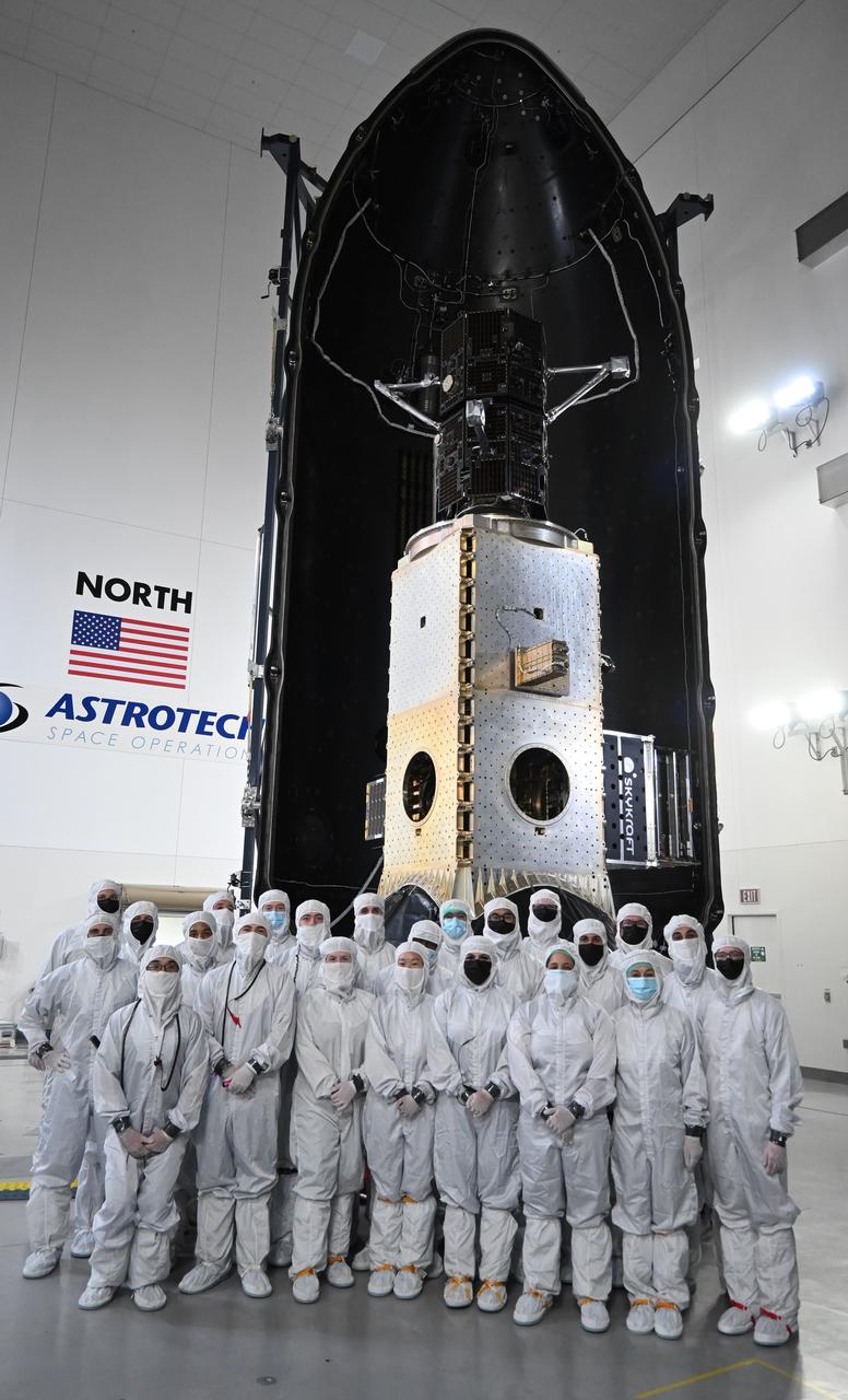
Technicians encapsulate the black twin satellites of NASA’s TRACERS (Tandem Reconnection and Cusp Electrodynamics Reconnaissance Satellites) mission within a payload fairing atop a shiny metallic stack of several other rideshare payloads at the Astrotech Space Operations facility at Vandenberg Space Force Base in California. The TRACERS mission is a pair of twin satellites that will study how Earth’s magnetic shield — the magnetosphere — protects our planet from the supersonic stream of material from the Sun called solar wind.
NASA’s TRACERS (Tandem Reconnection and Cusp Electrodynamics Reconnaissance Satellites) mission launches at 11:13 a.m. PDT (2:13 p.m. EDT) on Wednesday, July 23, 2025, atop a SpaceX Falcon 9 rocket at Space Launch Complex 4 East at Vandenberg Space Force Base in California. The TRACERS mission will study magnetic reconnection around Earth — a process in which electrically charged plasmas exchange energy in the atmosphere — to understand how the Sun’s solar wind interacts with the magnetosphere, Earth’s protective magnetic shield.

A SpaceX Falcon 9 rocket carrying NASA’s TRACERS (Tandem Reconnection and Cusp Electrodynamics Reconnaissance Satellites) mission stands vertical Tuesday, July 22, 2025, at Space Launch Complex 4 East at Vandenberg Space Force Base in California. The TRACERS mission will study magnetic reconnection around Earth — a process in which electrically charged plasmas exchange energy in the atmosphere — to understand how the Sun’s solar wind interacts with the magnetosphere, Earth’s protective magnetic shield.
NASA’s TRACERS (Tandem Reconnection and Cusp Electrodynamics Reconnaissance Satellites) mission launches at 11:13 a.m. PDT (2:13 p.m. EDT) on Wednesday, July 23, 2025, atop a SpaceX Falcon 9 rocket at Space Launch Complex 4 East at Vandenberg Space Force Base in California. The TRACERS mission will study magnetic reconnection around Earth — a process in which electrically charged plasmas exchange energy in the atmosphere — to understand how the Sun’s solar wind interacts with the magnetosphere, Earth’s protective magnetic shield.
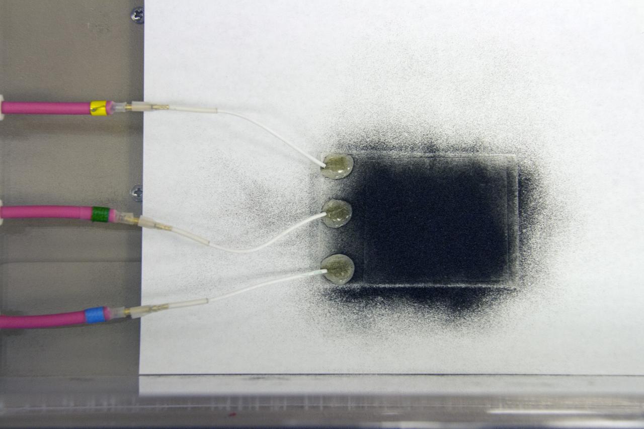
Inside of the Electrostatics and Surface Physics Laboratory at NASA’s Kennedy Space Center in Florida, an electrodynamic dust shield (EDS) is in view on Jan. 18, 2023. The dust shield is one of the payloads that will fly aboard Firefly Aerospace’s Blue Ghost lunar lander as part of NASA’s Commercial Lunar Payload Services (CLPS) initiative. During the mission, EDS will generate a non-uniform electric field using varying high voltage on multiple electrodes. This traveling field, in turn, carries away the particles and has potential applications in thermal radiators, spacesuit fabrics, visors, camera lenses, solar panels, and many other technologies. The CLPS initiative is a key part of NASA’s Artemis lunar exploration efforts. The science and technology payloads sent to the Moon’s surface as part of the initiative will help lay the foundation for human missions and a sustainable human presence on the lunar surface.
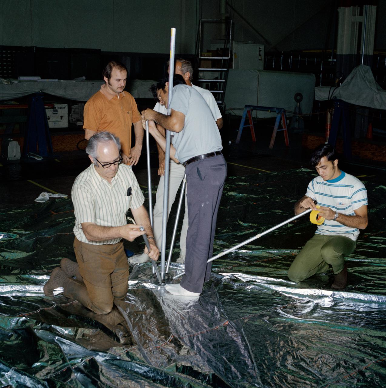
Engineers from the Marshall Space Flight Center (MSFC) and its contractors were testing the twin-pole sunshade at the Skylab mockup in the MSFC Building 4619. The Skylab Orbital Workshop (OWS) lost its thermal protection shield during launch on May 14, 1963. Without the heat shield, the temperature inside the OWS became dangerously high, rendering the workshop uninhabitable and threatened deterioration of the interior insulation and adhesive. Engineers from the MSFC, its contractors, and NASA persornel at other centers worked day and night for several days to develop the way to save the Skylab OWS. Eventually, they developed, tested, rehearsed, and approved three repair options. These options included a parasol sunshade and a twin-pole sunshade to restore the temperature inside the workshop, and a set of metal cutting tools to free the jammed solar panel.
Inside of the Electrostatics and Surface Physics Laboratory at NASA’s Kennedy Space Center in Florida, an electrodynamic dust shield (EDS) is in view on Jan. 18, 2023. The dust shield is one of the payloads that will fly aboard Firefly Aerospace’s Blue Ghost lunar lander as part of NASA’s Commercial Lunar Payload Services (CLPS) initiative. During the mission, EDS will generate a non-uniform electric field using varying high voltage on multiple electrodes. This traveling field, in turn, carries away the particles and has potential applications in thermal radiators, spacesuit fabrics, visors, camera lenses, solar panels, and many other technologies. The CLPS initiative is a key part of NASA’s Artemis lunar exploration efforts. The science and technology payloads sent to the Moon’s surface as part of the initiative will help lay the foundation for human missions and a sustainable human presence on the lunar surface.
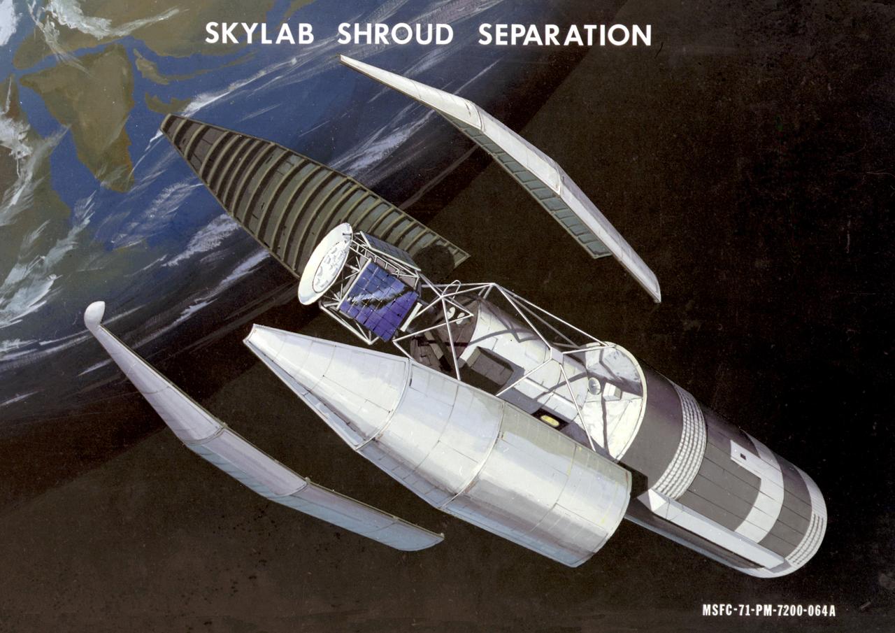
This artist's concept depicts the separation of the Skylab payload shroud. The payload shroud was both an environmental shield and an aerodynamic fairing. Attached to the forward end of the fixed airlock shroud, it protected the airlock, the docking adapter, and the solar observatory before and during launch. It also provided structural support for the solar observatory in the launch configuration. The payload shroud was jettisoned once Skylab reached orbit after separation of the S-II second stage of the Saturn V vehicle. Five major assemblies clustered together made up the orbiting space station called Skylab. The largest of these was the orbital workshop, that housed the crew quarters and a major experiment area. The airlock module, attached to the forward end of the workshop, enabled crewmembers to make excursions outside Skylab. The docking adapter, attached to the forward end of the airlock module, provided the docking port for the Apollo command and service module. The Apollo Telescope Mount was the first marned astronomical observatory designed for solar research from Earth orbit.

A metal strap became tangled over one of the folded solar array panels when Skylab lost its micro meteoroid shield during its launch. Cutters like the ones used to free the solar array were used to cut the ribbon opening to the public a new full-scale Skylab cluster exhibit at the Alabama Space and Rocket Center in Huntsville, Alabama. Wielding the cutters are (left to right): Alabama Senator James B. Allen; Marshall Space Flight Center director, Dr. William R. Lucas, Huntsville Mayor, Joe Davis; Madison County Commission Chairman, James Record (standing behind Mayor Davis); and chairman of the Alabama Space Science Exhibit Commission, Jack Giles. Astronauts Conrad and Kerwin used the same type of tool in Earth orbit to cut the aluminum strap which jammed the Skylab solar array.
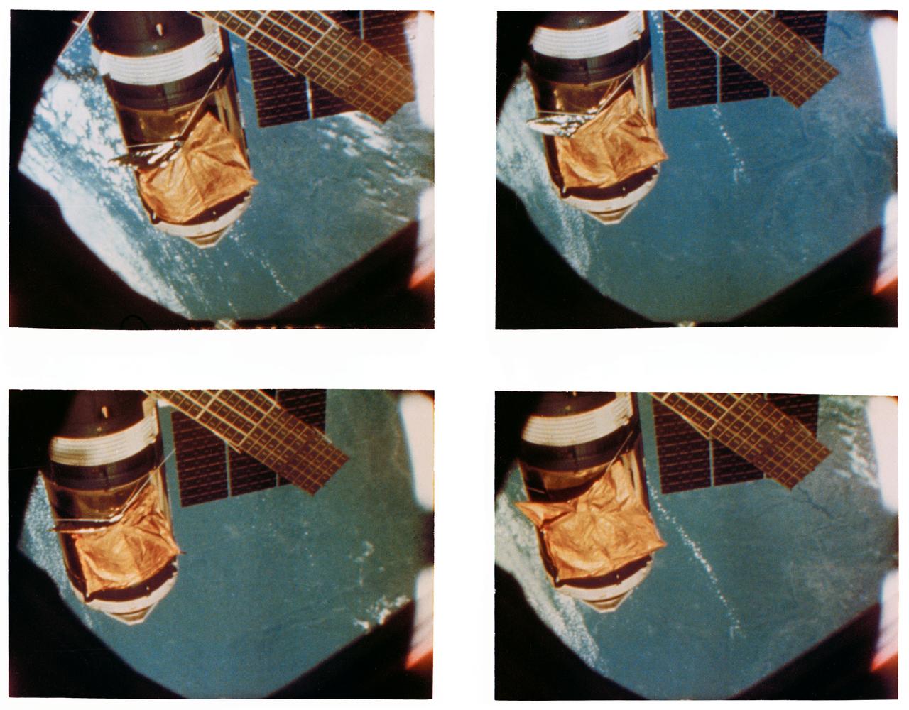
S73-34619 (28 July 1973) --- A composite of four frames taken from 16mm movie camera footage showing an overhead view of the Skylab space station cluster in Earth orbit. The Maurer motion picture camera scenes were being filmed during the Skylab 3 Command/Service Module's (CSM) first "fly around" inspection of the space station. Close comparison of the four frames reveals movement of the improvised parasol solar shield over the Orbital Workshop (OWS). The "flapping" of the sun shade was caused from the exhaust of the reaction control subsystem (RCS) thrusters of the Skylab 3 CSM. The one remaining solar array system wing on the OWS is in the lower left background. The solar panel in the lower left foreground is on the Apollo Telescope Mount (ATM). Photo credit: NASA
In the Kennedy Space Center’s Press Site auditorium, on Friday, July 20, 2018, Betsy Congdon, Thermal Protection System engineer with the Johns Hopkins University Applied Physics Laboratory, right, demonstrates the ability of the Parker Solar Probe's heat shield to protect the spacecraft. The presentation for the media took place during a prelaunch mission briefing for the Parker Solar Probe mission. The Parker Solar Probe will lift off on a United Launch Alliance Delta IV Heavy rocket from Space Launch Complex 37 at Cape Canaveral Air Force Station in Florida. The spacecraft was built by Applied Physics Laboratory of Johns Hopkins University in Laurel in Maryland. The mission will perform the closest-ever observations of a star when it travels through the Sun's atmosphere, called the corona. The probe will rely on measurements and imaging to revolutionize understanding of the corona and the Sun-Earth connection.
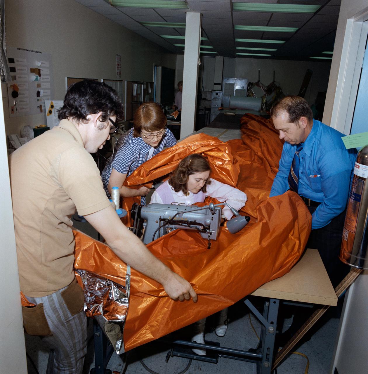
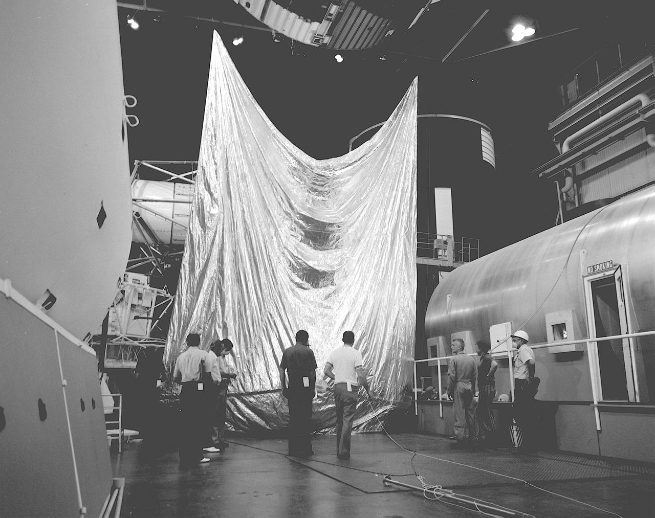
S73-26047 (18 May 1973) --- A sail-like sunshade for possible use as a sunscreen for the Skylab orbital workshop (OWS) is shown being fabricated in the GE Building across the street from the Johnson Space Center. Three persons assist the seamstress feed the material through the sewing machine. The three-layered shade will be composed of a top layer of aluminum Mylar, a middle layer of laminated nylon rip stop, and a bottom layer of thin nylon. Working on the sunshade, from left to right, are Dale Gentry, Elizabeth Gauldin, Alyene Baker and James H. Barnett Jr. Mrs. Baker, a GE employee, operates the double-needle sewing machine. Barnett is head of the Crew Equipment Development Section of JSC's Crew Systems Division. Mrs. Gauldin is also with the Crew Systems Division. Gentry works for GE. The work shown here is part of the crash program underway to prepare a protection device for Skylab to replace the original shield which was lost when the unmanned Skylab 1 launch took place on May 14, 1973. The improvised solar shield selected to be used will be carried to Earth orbit by the Skylab 2 crew, who will deploy it to shade part of the OWS from the hot rays of the sun. Loss of the original shield, as expected, has caused an overheating problem on the OWS. Photo credit: NASA
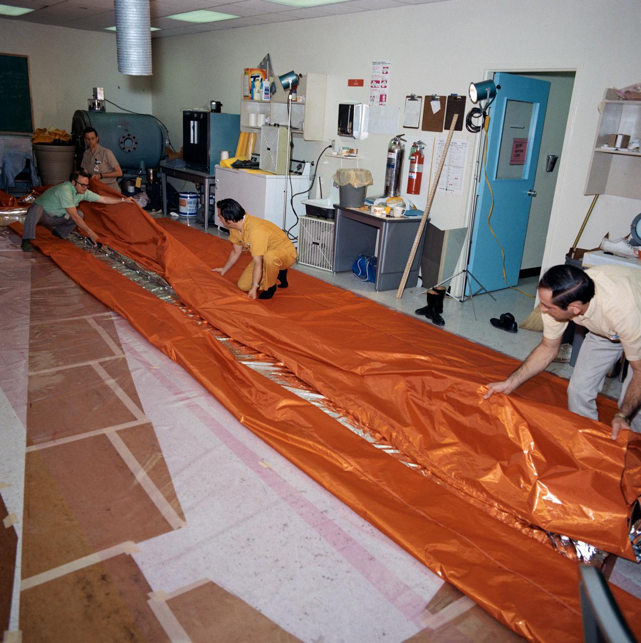
S73-26046 (18 May 1973) --- Workmen in the GE Building across the street from the Johnson Space Center fold a sail-like sunshade being fabricated for possible use as a sunscreen for the Skylab Orbital Workshop (OWS). The three-layered sunshade will be composed of a top layer of aluminized mylar, a middle layer of laminated nylon rip-stop, and a bottom layer of thin nylon. The men are, left to right, Gerry E. Wood (wearing glasses), Glenn Hewitt, Pat Morrow, and Fred Le Donne. Wood is manager of crew provisions and engineering at GE. The work shown here is part of the crash program now underway to prepare a sunshield for Skylab to replace the original shield which was lost when Skylab I was launched on May 14, 1973. The improvised solar shield selected to be used will be carried to Earth orbit by the Skylab 2 crewmen who will deploy it to shade part of the OWS from the hot rays of the sun. Loss of the original shield has caused an overheating problem in the OWS. Photo credit: NASA
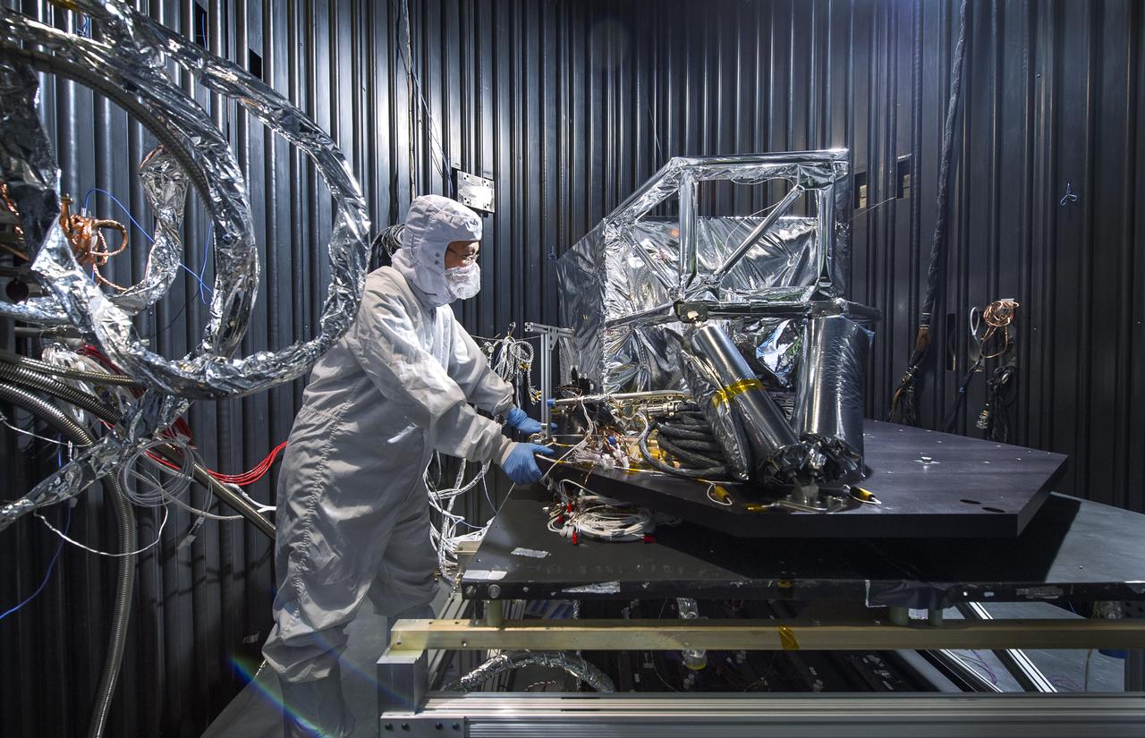
NASA engineer Acey Herrera recently checked out copper test wires inside the thermal shield of the Mid-Infrared Instrument, known as MIRI, that will fly aboard NASA's James Webb Space Telescope. The shield is designed to protect the vital MIRI instrument from excess heat. At the time of the photo, the thermal shield was about to go through rigorous environmental testing to ensure it can perform properly in the extreme cold temperatures that it will encounter in space. Herrera is working in a thermal vacuum chamber at NASA's Goddard Space Flight Center in Greenbelt, Md. As the MIRI shield lead, Herrera along with a thermal engineer and cryo-engineer verify that the shield is ready for testing. On the Webb telescope, the pioneering camera and spectrometer that comprise the MIRI instrument sit inside the Integrated Science Instrument Module flight structure, that holds Webb's four instruments and their electronic systems during launch and operations. Read more: <a href="http://1.usa.gov/15I0wrS" rel="nofollow">1.usa.gov/15I0wrS</a> Credit: NASA/Chris Gunn <b><a href="http://www.nasa.gov/audience/formedia/features/MP_Photo_Guidelines.html" rel="nofollow">NASA image use policy.</a></b> <b><a href="http://www.nasa.gov/centers/goddard/home/index.html" rel="nofollow">NASA Goddard Space Flight Center</a></b> enables NASA’s mission through four scientific endeavors: Earth Science, Heliophysics, Solar System Exploration, and Astrophysics. Goddard plays a leading role in NASA’s accomplishments by contributing compelling scientific knowledge to advance the Agency’s mission. <b>Follow us on <a href="http://twitter.com/NASA_GoddardPix" rel="nofollow">Twitter</a></b> <b>Like us on <a href="http://www.facebook.com/pages/Greenbelt-MD/NASA-Goddard/395013845897?ref=tsd" rel="nofollow">Facebook</a></b> <b>Find us on <a href="http://instagram.com/nasagoddard?vm=grid" rel="nofollow">Instagram</a></b>
SL3-114-1683 (28 July 1973) --- A close-up view of the Skylab space station photographed against an Earth background from the Skylab 3 Command and Service Modules (CSM) during station-keeping maneuvers prior to docking. Aboard the Command Module (CM) were astronauts Alan L. Bean, Owen K. Garriott and Jack R. Lousma, who remained with the Skylab Space Station in Earth orbit for 59 days. This picture was taken with a hand-held 70mm Hasselblad camera using a 100mm lens and SO-368 medium speed Ektachrome film. Note the one solar array system wing on the Orbital Workshop (OWS) which was successfully deployed during extravehicular activity (EVA) on the first manned Skylab flight. The parasol solar shield which was deployed by the Skylab 2 crew can be seen through the support struts of the Apollo Telescope Mount (ATM). Photo credit: NASA
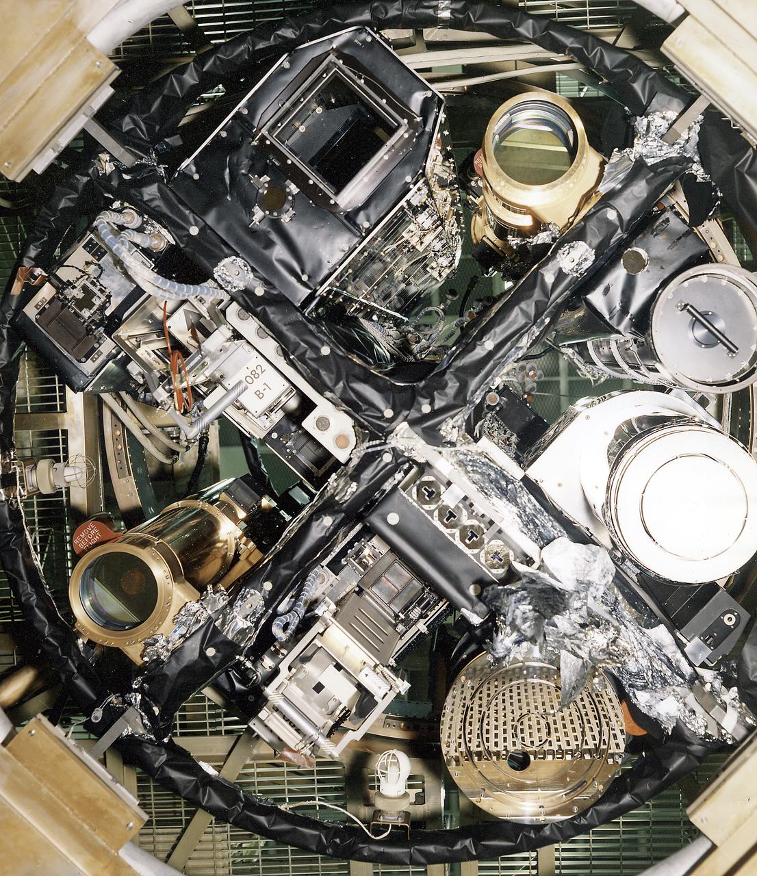
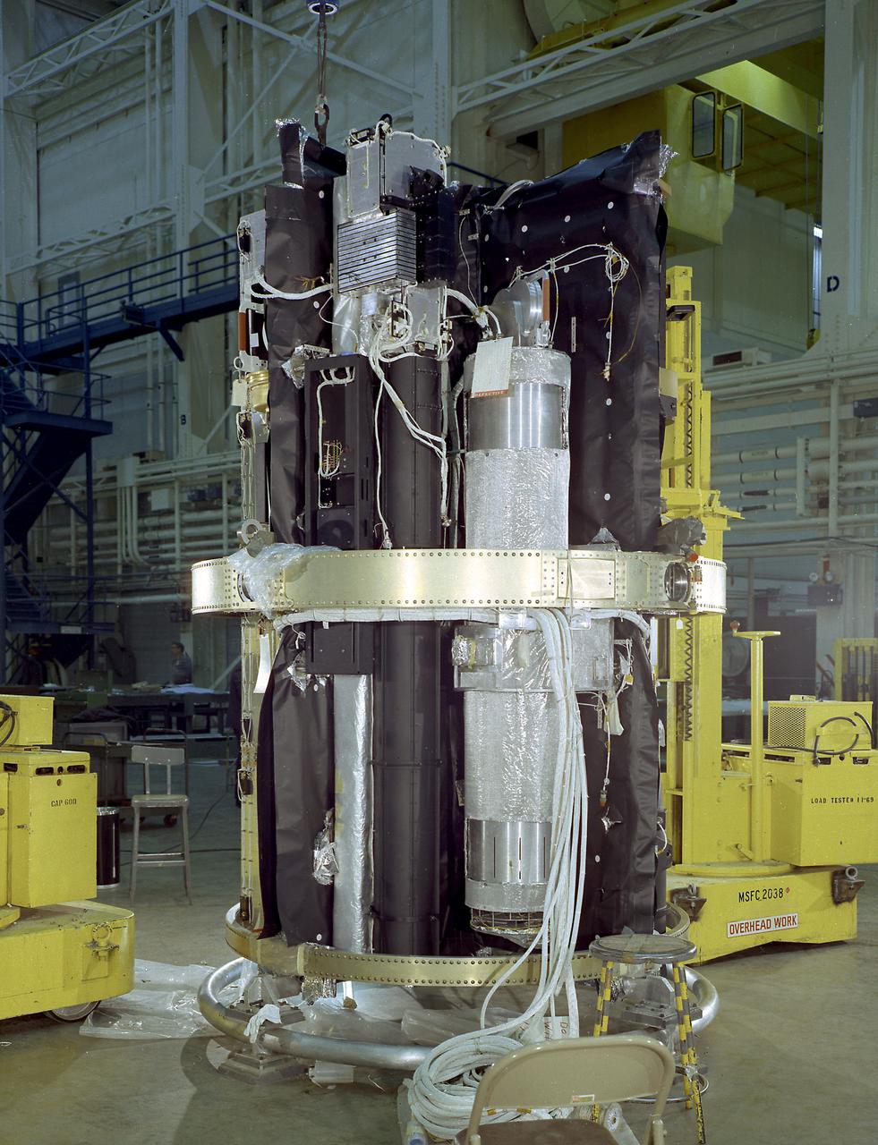
The Apollo Telescope Mount (ATM) was designed and developed by the Marshall Space Flight Center and served as the primary scientific instrument unit aboard Skylab (1973-1979). The ATM contained eight complex astronomical instruments designed to observe the Sun over a wide spectrum from visible light to x-rays. This image depicts the sun end and spar of the ATM flight unit showing individual telescopes. All solar telescopes, the fine Sun sensors, and some auxiliary systems are mounted on the spar, a cruciform lightweight perforated metal mounting panel that divides the canister lengthwise into four equal compartments. The spar assembly was nested inside a cylindrical canister that fit into a complex frame named the rack, and was protected by the solar shield.
S73-26380 (23 May 1973) --- Technicians in the Technical Services shop in Building 10 work on the fabrication of the umbrella-like mechanical device called the “parasol” during Skylab 2 preflight preparations at NASA's Johnson Space Center. Here, they are attaching the telescoping extension rods to the canopy. The “parasol” is designed to fit into the TO27 experiment photometer canister. The canopy is 24 feet by 22 feet. The sunshade device will be deployed through the solar scientific airlock in the side of the OWS. The “parasol” solar shield is considered the prime possibility for use as the OWS sunshade because it will not require EVA by the Skylab 2 crewmen, because of the operational ease of using it, and because of the simplicity of the device which minimizes crew training. Photo credit: NASA
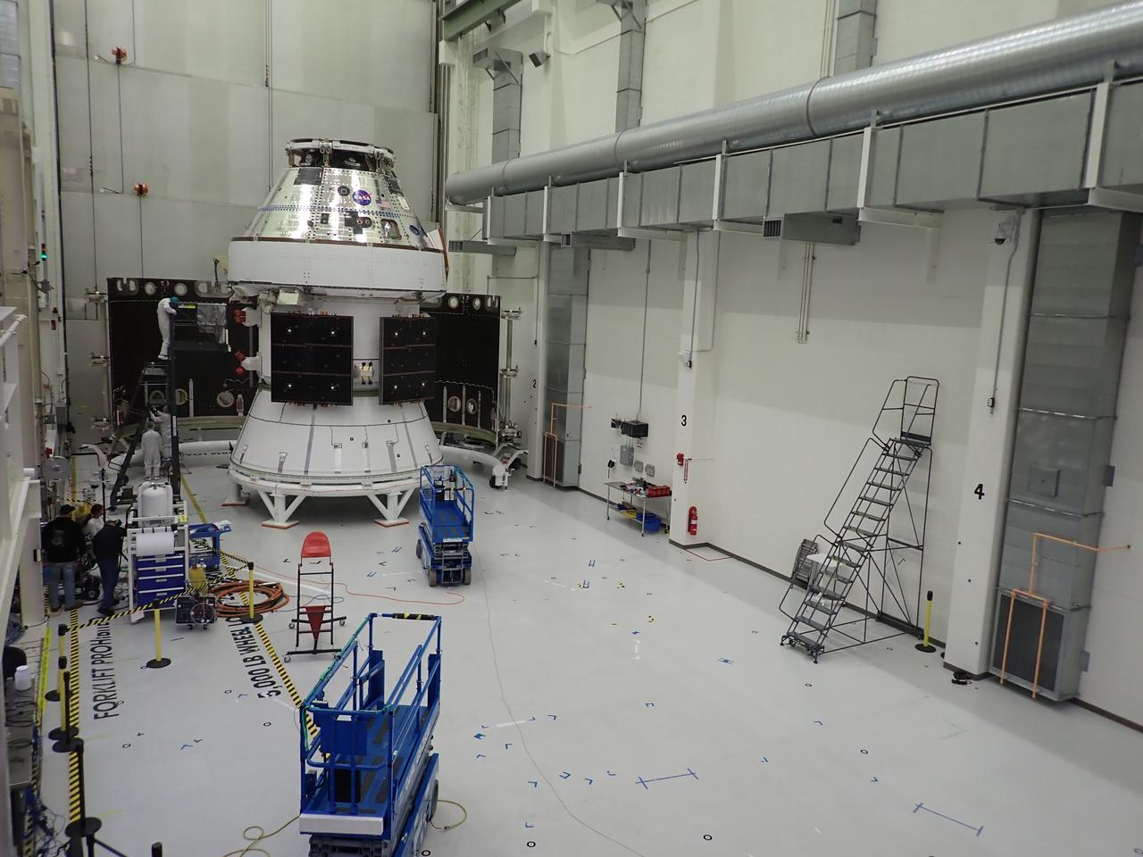
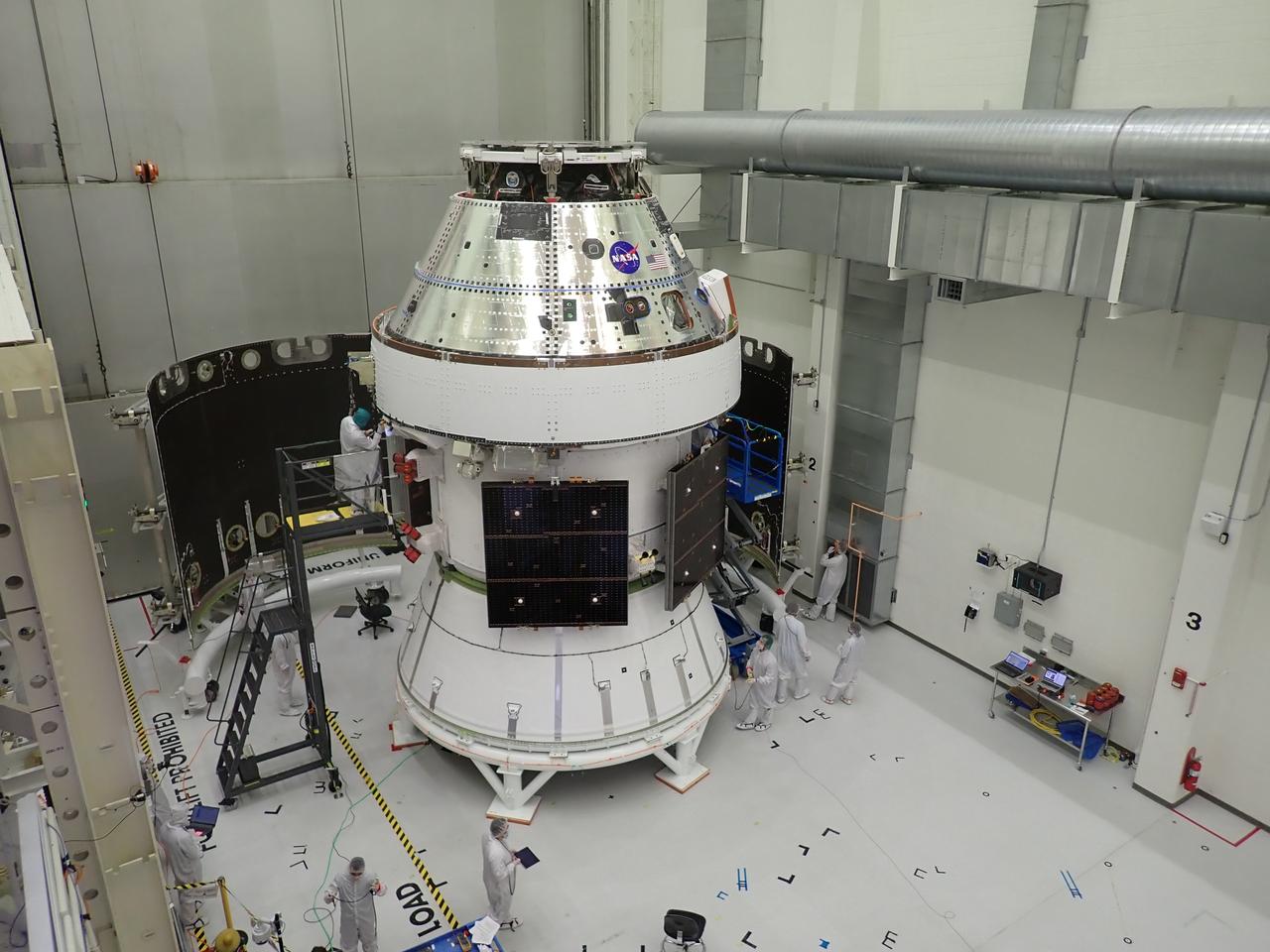
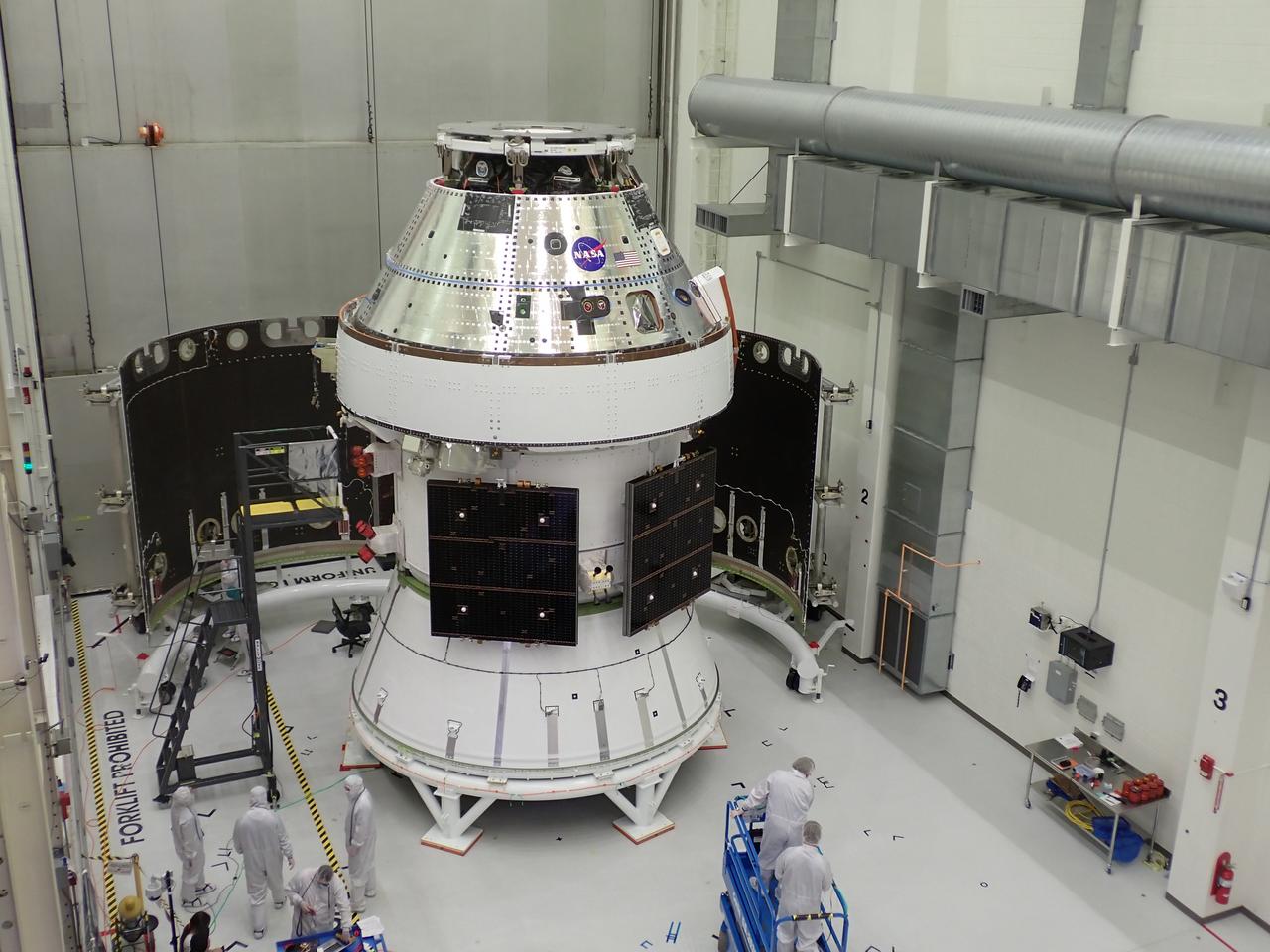
Technicians with Lockheed Martin prepare the Artemis II Orion spacecraft for the installation of three spacecraft adapter jettison fairings inside the Neil A. Armstrong Operations and Checkout Building at NASA’s Kennedy Space Center in Florida in on Tuesday, March 11, 2025. The fairings encapsulate the service module and protect the solar array wings, shielding them from the heat, wind, and acoustics of launch and ascent, plus help redistribute the load between Orion and the massive thrust of the SLS (Space Launch System) rocket during liftoff and ascent. Once the spacecraft is above the atmosphere, the three fairing panels will separate from the service module reducing the mass of the spacecraft.
S73-31976 (5 Aug. 1973) --- Astronaut Jack R. Lousma, Skylab 3 pilot, is seen outside the Skylab space station in Earth orbit during the Aug. 5, 1973 Skylab 3 extravehicular activity (EVA) in this photographic reproduction taken from a television transmission made by a color TV camera aboard the space station. Scientist-astronaut Owen K. Garriott, Skylab 3 science pilot, participated in the EVA with Lousma. During the EVA the two crewmen deployed the twin pole solar shield to help shade the Orbital Workshop. Photo credit: NASA
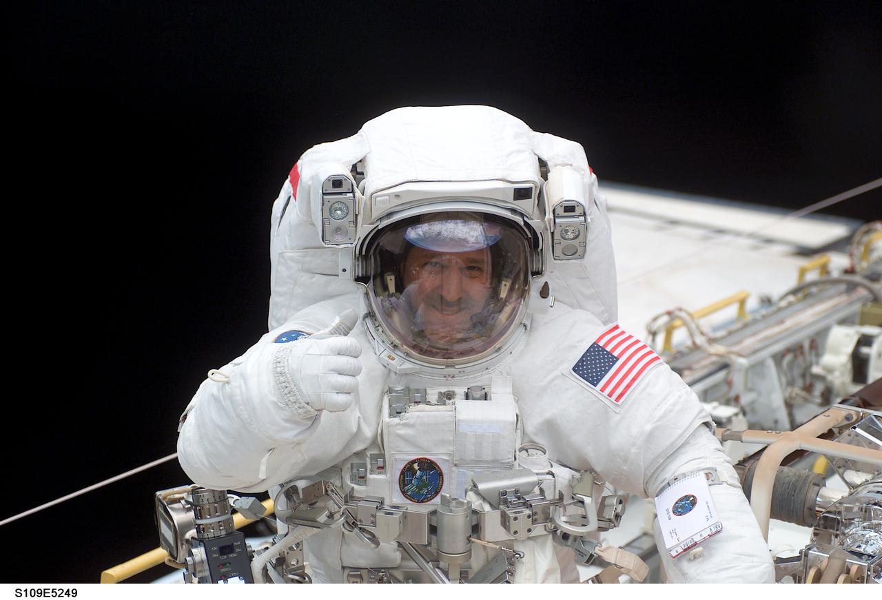
STS109-322-028 (6 March 2002) --- Astronaut Richard M. Linnehan, STS-109 mission specialist, participates in the third of five space walks to perform work on the Hubble Space Telescope (HST). Linnehan's sun shield reflects astronaut John M. Grunsfeld and the blue and white Earth's hemisphere as well as one of the telescope's new solar arrays. The third overall STS-109 extravehicular activity (EVA) marked the second of three for Linnehan and Grunsfeld, payload commander. On this particular walk, the two turned off the telescope in order to replace the power control unit or PCU--the heart of its power system. Grunsfeld took this photo with a 35mm camera.
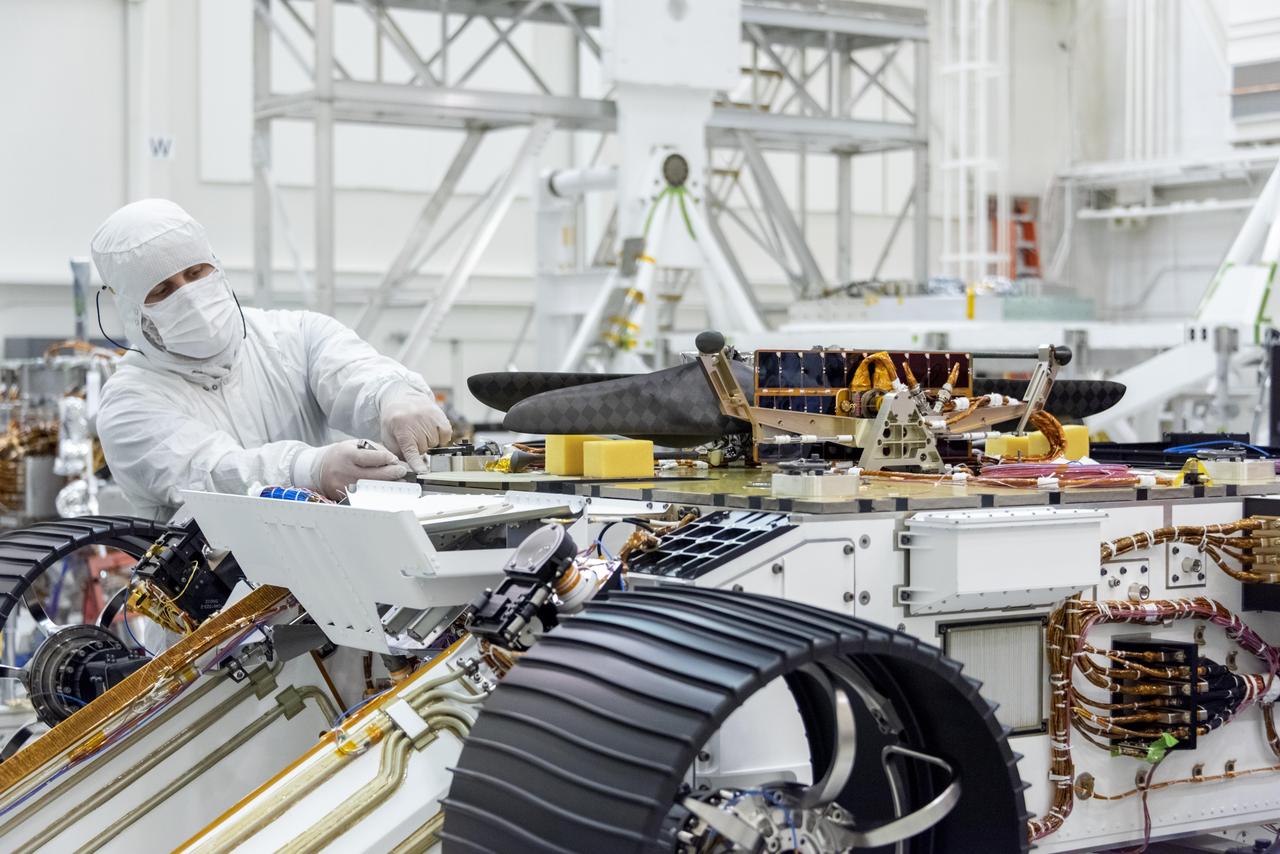
An engineer works on attaching NASA's Mars Helicopter to the belly of the Mars 2020 rover — which has been flipped over for that purpose — on Aug. 28, 2019, at the Jet Propulsion Laboratory in Pasadena, California. The twin-rotor, solar-powered helicopter was mechanically connected, along with the Mars Helicopter Delivery System, to a plate on the rover's belly that includes a cover to shield the helicopter from debris during entry, descent and landing. The helicopter will remain encapsulated after landing, deploying to the surface once a suitable area to conduct test flights is found at Jezero Crater, the rover's destination. https://photojournal.jpl.nasa.gov/catalog/PIA23372
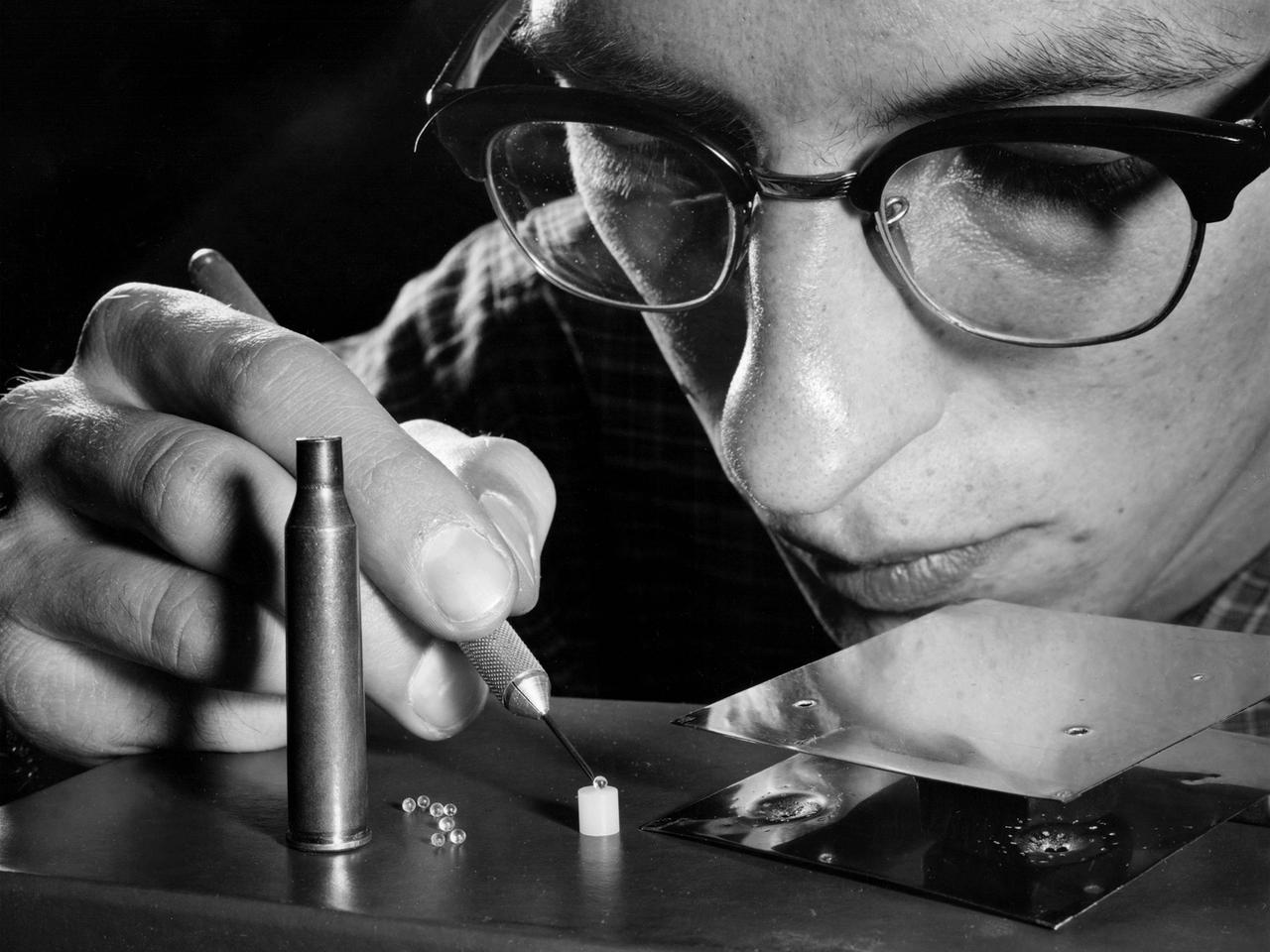
A researcher at the NASA Lewis Research Center manipulates cartridge pellets and a strain gauge target as part of a study on the impact of micrometeorites striking space vehicles. Early in the space program NASA researchers were concerned that small micrometeorites would penetrate spacecraft, injure engines, or damage solar arrays. In response, researchers worked to develop stronger materials to withstand meteorite strikes and screens to block the objects. NASA launched a series of experimental spacecraft into orbit with foil shields that were used to determine the number of meteorite strikes. By the early 1960s the experiments and computer modelling efforts revealed that the micrometeoroid threat was lower than previously anticipated.
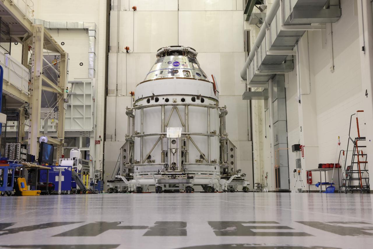
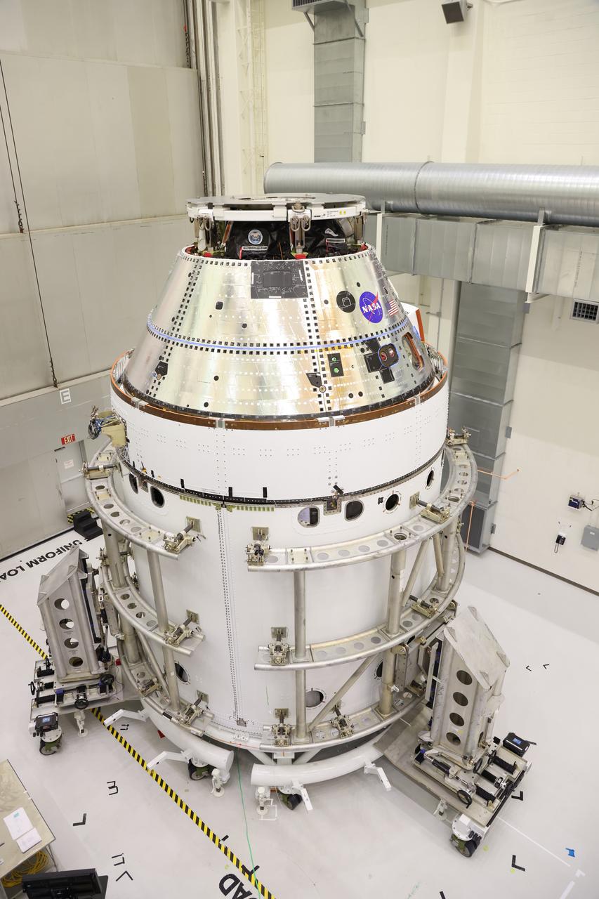
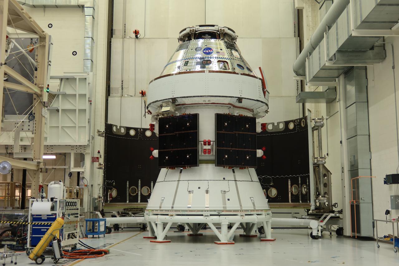
The Artemis II Orion spacecraft sits in the transfer aisle in the Neil A. Armstrong Operations and Checkout Building at NASA’s Kennedy Space Center in Florida following successful installation of three spacecraft adapter jettison fairings on Wednesday, March 19, 2025. The fairings encapsulate the service module and protect the solar array wings, shielding them from the heat, wind, and acoustics of launch and ascent, as well as help redistribute the load between Orion and the massive thrust of the SLS (Space Launch System) rocket during liftoff and ascent. Once the spacecraft is above the atmosphere, the three fairing panels will separate from the service module reducing the mass of the spacecraft.
The Artemis II Orion spacecraft sits in the transfer aisle in the Neil A. Armstrong Operations and Checkout Building at NASA’s Kennedy Space Center in Florida following successful installation of three spacecraft adapter jettison fairings on Wednesday, March 19, 2025. The fairings encapsulate the service module and protect the solar array wings, shielding them from the heat, wind, and acoustics of launch and ascent, as well as help redistribute the load between Orion and the massive thrust of the SLS (Space Launch System) rocket during liftoff and ascent. Once the spacecraft is above the atmosphere, the three fairing panels will separate from the service module reducing the mass of the spacecraft.
The Artemis II Orion spacecraft sits in the transfer aisle in the Neil A. Armstrong Operations and Checkout Building at NASA’s Kennedy Space Center in Florida following successful installation of three spacecraft adapter jettison fairings on Wednesday, March 19, 2025. The fairings encapsulate the service module and protect the solar array wings, shielding them from the heat, wind, and acoustics of launch and ascent, as well as help redistribute the load between Orion and the massive thrust of the SLS (Space Launch System) rocket during liftoff and ascent. Once the spacecraft is above the atmosphere, the three fairing panels will separate from the service module reducing the mass of the spacecraft.
Technicians with Lockheed Martin prepare the Artemis II Orion spacecraft for the installation of three spacecraft adapter jettison fairings inside the Neil A. Armstrong Operations and Checkout Building at NASA’s Kennedy Space Center in Florida in on Tuesday, March 11, 2025. The fairings encapsulate the service module and protect the solar array wings, shielding them from the heat, wind, and acoustics of launch and ascent, plus help redistribute the load between Orion and the massive thrust of the SLS (Space Launch System) rocket during liftoff and ascent. Once the spacecraft is above the atmosphere, the three fairing panels will separate from the service module reducing the mass of the spacecraft.
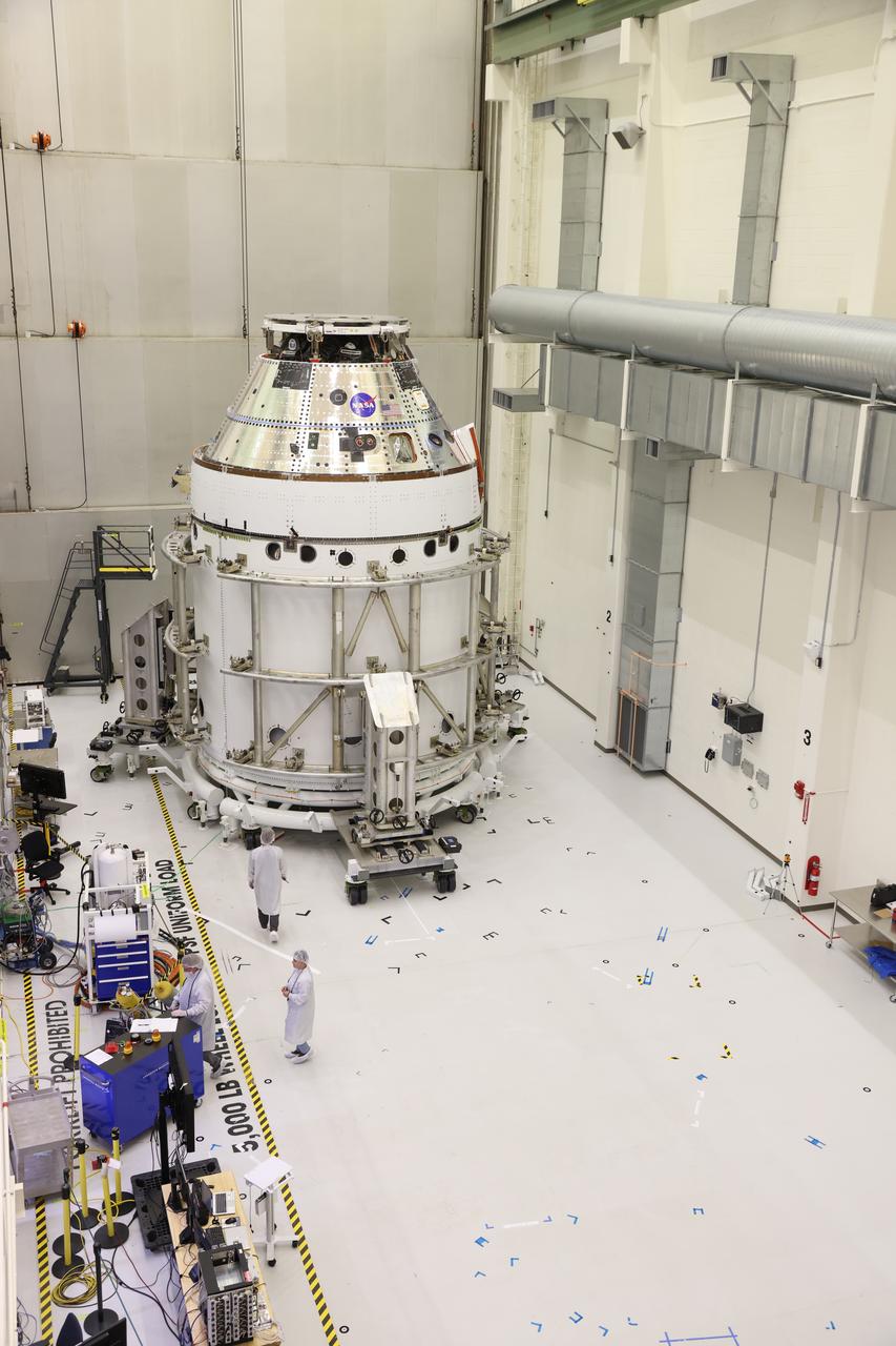
The Artemis II Orion spacecraft sits in the transfer aisle in the Neil A. Armstrong Operations and Checkout Building at NASA’s Kennedy Space Center in Florida in preparation for the installation of three spacecraft adapter jettison fairings on Tuesday, March 11, 2025. The fairings encapsulate the service module and protect the solar array wings, shielding them from the heat, wind, and acoustics of launch and ascent, plus help redistribute the load between Orion and the massive thrust of the SLS (Space Launch System) rocket during liftoff and ascent. Once the spacecraft is above the atmosphere, the three fairing panels will separate from the service module reducing the mass of the spacecraft.
Technicians with Lockheed Martin prepare the Artemis II Orion spacecraft for the installation of three spacecraft adapter jettison fairings inside the Neil A. Armstrong Operations and Checkout Building at NASA’s Kennedy Space Center in Florida in on Tuesday, March 11, 2025. The fairings encapsulate the service module and protect the solar array wings, shielding them from the heat, wind, and acoustics of launch and ascent, plus help redistribute the load between Orion and the massive thrust of the SLS (Space Launch System) rocket during liftoff and ascent. Once the spacecraft is above the atmosphere, the three fairing panels will separate from the service module reducing the mass of the spacecraft.
STS109-E-5249 (4 March 2002) --- In Columbia's cargo bay, astronaut John M. Grunsfeld (foreground), payload commander, signals to a crewmate inside the crew cabin. He had just raised his helmet visor's sun shield. Astronauts Grunsfeld and Richard M. Linnehan (out of frame), mission specialist, participating in the first of their assigned STS-109 space walks to perform work on the Hubble Space Telescope (HST), went on to replace the giant telescope’s starboard solar array. Their seven-hour space walk ended at 7:38 a.m. (CST) or 13:38 GMT March 4, 2002.
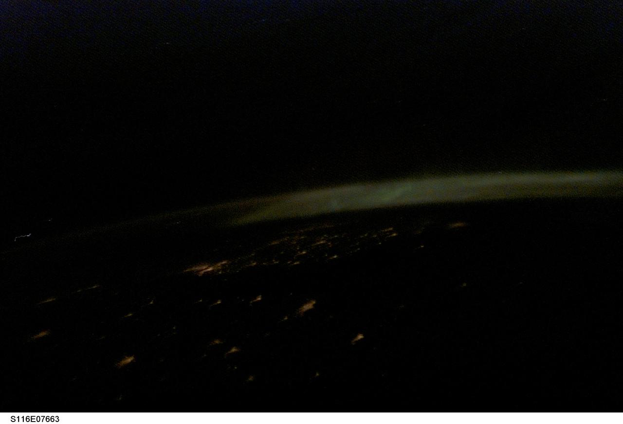
S116-E-07663 (20 Dec. 2006) --- One of the STS-116 crewmembers onboard the Space Shuttle Discovery captured this picture of Aurora Borealis over Norway, Poland and Sweden, as the crew made preparations for a Dec. 22 landing. European Space Agency astronaut Christer Fuglesang onboard the shuttle noted the rarity of pictures over this area from shuttle missions, and especially pictures that included the Northern Lights. Fuglesang is from Sweden. The city lights of Copenhagen (bright cluster of lights in the middle left portion of the image), Stockholm (under the aurora on the far right side of the image), and Gdansk (in the center forefront) are seen. The formation of the aurora starts with the sun releasing solar particles. The Earth's magnetic field captures and channels the solar particles toward the Earth's two magnetic poles (north and south). As the solar particles move towards the poles they collide with the Earth's atmosphere, which acts as an effective shield against these deadly particles. The collision between the solar particles and the atmospheric gas molecule emits a light particle (photon). When there are many collisions the aurora is formed.
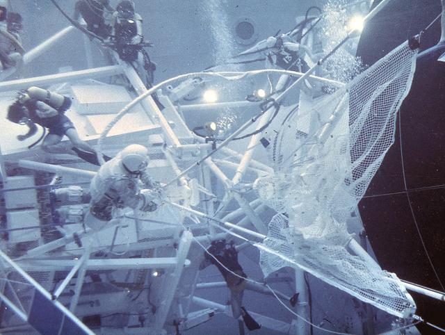
After its launch on May 14, 1973, it was immediately known that there were some major problems with Skylab. The large, delicate, meteoroid shield on the outside of the workshop was ripped off by the vibration of the launch. Its tearing off caused serious damage to the two wings of solar cells that were to supply most of the electric power to the workshop. Once in orbit, the news worsened. The loss of the big shade exposed the metal skin of the workshop to the sun. Internal temperatures soared to 126 degrees F. This heat not only threatened its habitation by astronauts, but if prolonged, would cause serious damage to instruments and film. After twice delaying the launch of the first astronaut crew, engineers worked frantically to develop solutions to these problems and salvage the Skylab. After designing a protective solar sail to cover the workshop, crews needed to practice using the specially designed tools and materials to facilitate the repair procedure. Marshall Space Flight Center's Neutral Buoyancy Simulator (NBS), was used to practice these maneuvers. Pictured here are the astronauts in the NBS deploying the protecticve solar sail. On may 25, 1973, an Apollo command and service module was launched and later docked with Skylab. The next day, astronauts Conrad and Kerwin were able to complete the needed repairs to Skylab, salvaging the entire program.

CAPE CANAVERAL, Fla. – In the Payload Hazardous Servicing Facility at NASA’s Kennedy Space Center in Florida, technicians move the heat shield carrier away from under the heat shield after integration with NASA's Mars Science Laboratory (MSL) mission aeroshell, (containing the compact car-sized rover Curiosity). Earlier, the aeroshell was mated to the cruise stage, which provides solar power, thrusters for navigation, and heat exchangers to the rover during its flight from Earth to Mars. The rover Curiosity has 10 science instruments designed to search for evidence on whether Mars has had environments favorable to microbial life, including chemical ingredients for life. The unique rover will use a laser to look inside rocks and release its gasses so that the rover’s spectrometer can analyze and send the data back to Earth. Launch of MSL aboard a United Launch Alliance Atlas V rocket is scheduled for Nov. 25 from Space Launch Complex 41 on Cape Canaveral Air Force Station in Florida. For more information, visit http:__www.nasa.gov_msl. Photo credit: NASA_Glenn Benson
Goddard Technicians Tony Kiem (left) and George Mooney (right) guide the craned structure holding the Webb telescope's Mid-Infrared Instrument or MIRI Shield Environmental Test Unit into place in a cryogenic (cooling) test chamber. This shield will be used to simulate the MIRI instrument during prelaunch testing to verify that the MIRI cooling system will function properly in space. Goddard Safety Engineer Richard Bowlan watches from above. Image Credit: NASA/Chris Gunn <b><a href="http://www.nasa.gov/audience/formedia/features/MP_Photo_Guidelines.html" rel="nofollow">NASA image use policy.</a></b> <b><a href="http://www.nasa.gov/centers/goddard/home/index.html" rel="nofollow">NASA Goddard Space Flight Center</a></b> enables NASA’s mission through four scientific endeavors: Earth Science, Heliophysics, Solar System Exploration, and Astrophysics. Goddard plays a leading role in NASA’s accomplishments by contributing compelling scientific knowledge to advance the Agency’s mission. <b>Follow us on <a href="http://twitter.com/NASA_GoddardPix" rel="nofollow">Twitter</a></b> <b>Like us on <a href="http://www.facebook.com/pages/Greenbelt-MD/NASA-Goddard/395013845897?ref=tsd" rel="nofollow">Facebook</a></b> <b>Find us on <a href="http://instagram.com/nasagoddard?vm=grid" rel="nofollow">Instagram</a></b>
CAPE CANAVERAL, Fla. – In the Payload Hazardous Servicing Facility at NASA’s Kennedy Space Center in Florida, technicians move the heat shield carrier away from under the heat shield after integration with NASA's Mars Science Laboratory (MSL) mission aeroshell, (containing the compact car-sized rover Curiosity). Earlier, the aeroshell was mated to the cruise stage, which provides solar power, thrusters for navigation, and heat exchangers to the rover during its flight from Earth to Mars. The rover Curiosity has 10 science instruments designed to search for evidence on whether Mars has had environments favorable to microbial life, including chemical ingredients for life. The unique rover will use a laser to look inside rocks and release its gasses so that the rover’s spectrometer can analyze and send the data back to Earth. Launch of MSL aboard a United Launch Alliance Atlas V rocket is scheduled for Nov. 25 from Space Launch Complex 41 on Cape Canaveral Air Force Station in Florida. For more information, visit http:__www.nasa.gov_msl. Photo credit: NASA_Glenn Benson
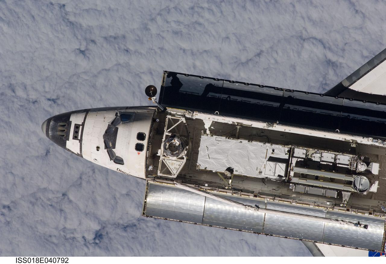
ISS018-E-040792 (17 March 2009) --- Backdropped by a blanket of clouds, Space Shuttle Discovery is featured in this image photographed by an Expedition 18 crewmember on the International Space Station during rendezvous and docking operations. Before docking with the station, astronaut Lee Archambault, STS-119 commander, flew the shuttle through a Rendezvous Pitch Maneuver or basically a backflip to allow the space station crew a good view of Discovery's heat shield. Using digital still cameras equipped with both 400 and 800 millimeter lenses, the ISS crewmembers took a number of photos of the shuttle's thermal protection system and sent them down to teams on the ground for analysis. A 400 millimeter lens was used for this image. Docking occurred at 4:20 p.m. (CDT) on March 17, 2009. The final pair of power-generating solar array wings and the S6 truss segment are visible in Discovery?s cargo bay.
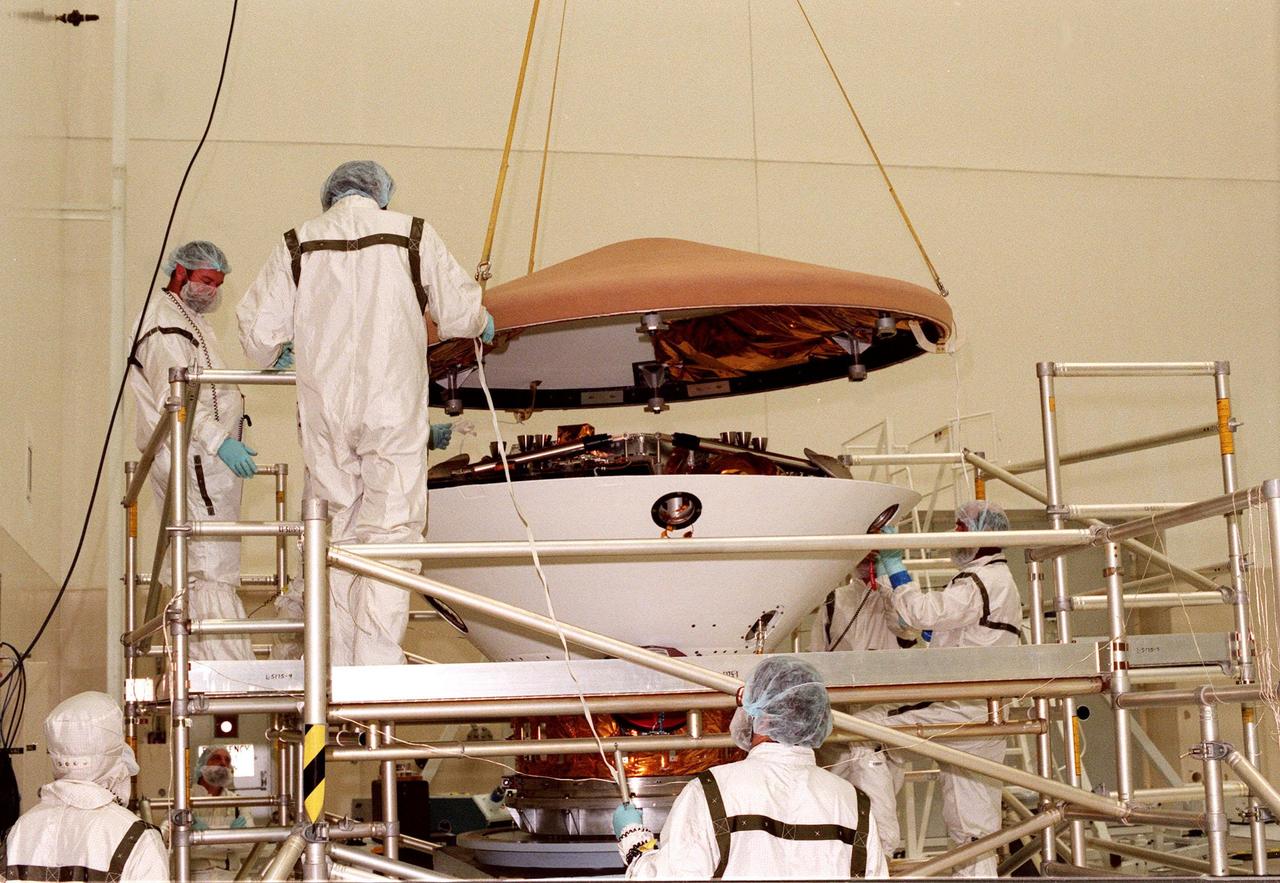
In the Spacecraft Assembly and Encapsulation Facility-2 (SAEF-2), workers lower the heat shield onto the Mars Polar Lander. Scheduled to be launched on Jan. 3, 1999, the lander is a solar-powered spacecraft designed to touch down on the Martian surface near the northern-most boundary of the south pole in order to study the water cycle there. The lander also will help scientists learn more about climate change and current resources on Mars, studying such things as frost, dust, water vapor and condensates in the Martian atmosphere. It is the second spacecraft to be launched in a pair of Mars '98 missions. The first is the Mars Climate Orbiter, which is due to be launched aboard a Delta II rocket from Launch Complex 17A on Dec. 11, 1998
Space Vacuum Epitaxy Center works with industry and government laboratories to develop advanced thin film materials and devices by utilizing the most abundant free resource in orbit: the vacuum of space. SVEC, along with its affiliates, is developing semiconductor mid-IR lasers for environmental sensing and defense applications, high efficiency solar cells for space satellite applications, oxide thin films for computer memory applications, and ultra-hard thin film coatings for wear resistance in micro devices. Performance of these vacuum deposited thin film materials and devices can be enhanced by using the ultra-vacuum of space for which SVEC has developed the Wake Shield Facility---a free flying research platform dedicated to thin film materials development in space.