The Direct Gain Solar Thermal Engine was designed with no moving parts. The concept of Solar Thermal Propulsion Research uses focused solar energy from an inflatable concentrator (a giant magnifying glass) to heat a propellant (hydrogen) and allows thermal expansion through the nozzle for low thrust without chemical combustion. Energy limitations and propellant weight associated with traditional combustion engines are non-existant with this concept. The Direct Gain Solar Thermal Engine would be used for moving from a lower orbit to an upper synchronous orbit.

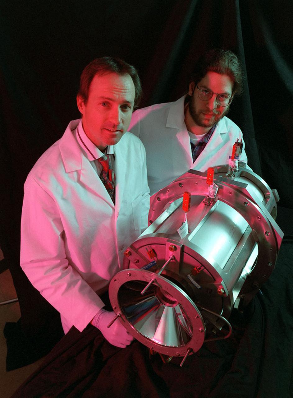
Researchers at the Marshall Space Flight Center (MSFC) have designed, fabricated, and tested the first solar thermal engine, a non-chemical rocket engine that produces lower thrust but has better thrust efficiency than a chemical combustion engine. This photograph shows components for the thermal propulsion engine being laid out prior to assembly. MSFC turned to solar thermal propulsion in the early 1990s due to its simplicity, safety, low cost, and commonality with other propulsion systems. As part of MSFC's Space Transportation Directorate, the Propulsion Research Center serves as a national resource for research of advanced, revolutionary propulsion technologies. The mission is to move the Nation's capabilities beyond the confines of conventional chemical propulsion into an era of aircraft-like access to Earth-orbit, rapid travel throughout the solar system, and exploration of interstellar space.
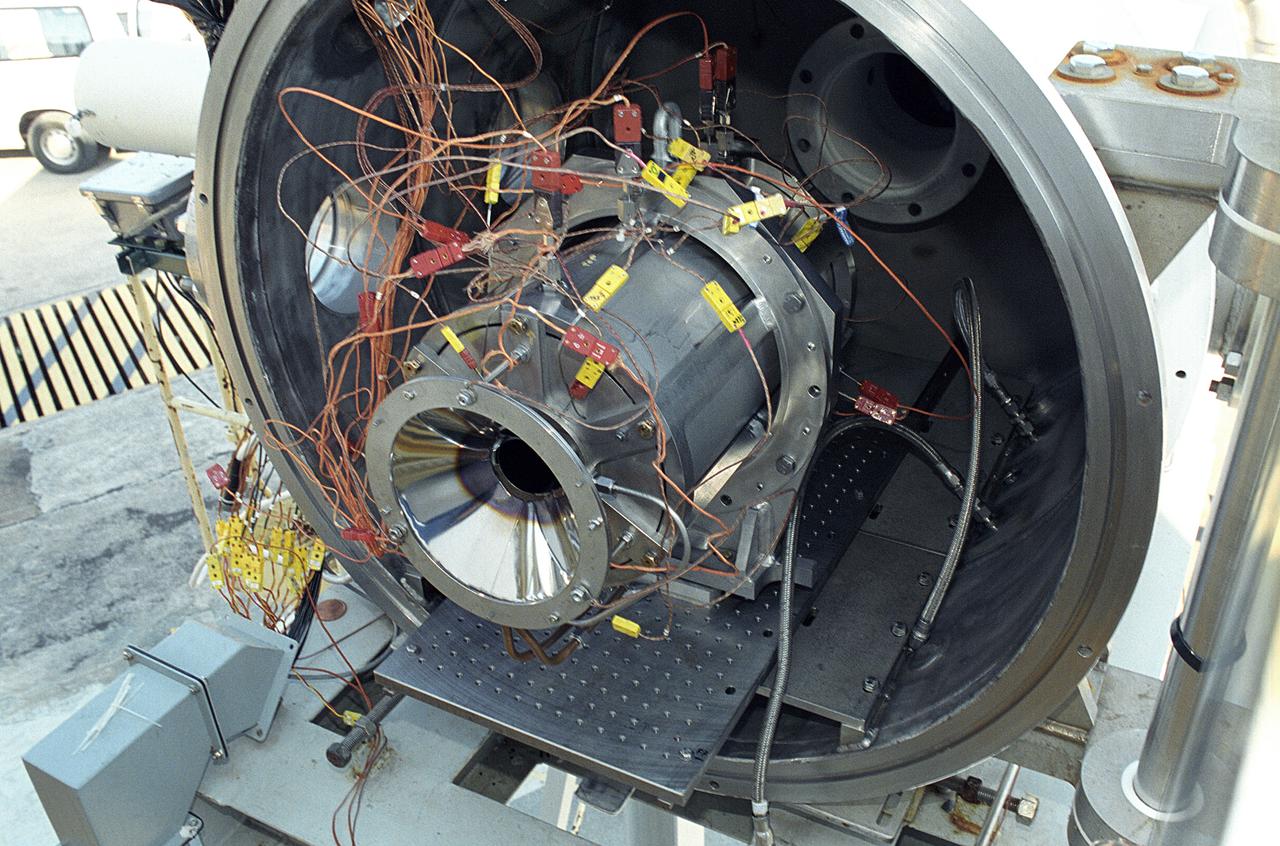
Researchers at the Marshall Space Flight Center (MSFC) have designed, fabricated, and tested the first solar thermal engine, a non-chemical rocket engine that produces lower thrust but has better thrust efficiency than a chemical combustion engine. MSFC turned to solar thermal propulsion in the early 1990s due to its simplicity, safety, low cost, and commonality with other propulsion systems. Solar thermal propulsion works by acquiring and redirecting solar energy to heat a propellant. This photograph shows a fully assembled solar thermal engine placed inside the vacuum chamber at the test facility prior to testing. The 20- by 24-ft heliostat mirror (not shown in this photograph) has a dual-axis control that keeps a reflection of the sunlight on the 18-ft diameter concentrator mirror, which then focuses the sunlight to a 4-in focal point inside the vacuum chamber. The focal point has 10 kilowatts of intense solar power. As part of MSFC's Space Transportation Directorate, the Propulsion Research Center serves as a national resource for research of advanced, revolutionary propulsion technologies. The mission is to move theNation's capabilities beyond the confines of conventional chemical propulsion into an era of aircraft-like access to Earth orbit, rapid travel throughout the solar system, and exploration of interstellar space.
A team of engineers at Marshall Space Flight Center (MSFC) has designed, fabricated, and tested the first solar thermal engine, a non-chemical rocket that produces lower thrust but has better thrust efficiency than the chemical combustion engines. This segmented array of mirrors is the solar concentrator test stand at MSFC for firing the thermal propulsion engines. The 144 mirrors are combined to form an 18-foot diameter array concentrator. The mirror segments are aluminum hexagons that have the reflective surface cut into it by a diamond turning machine, which is developed by MSFC Space Optics Manufacturing Technology Center.
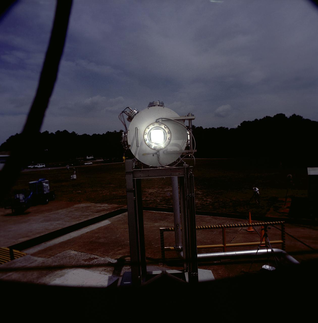
Researchers at the Marshall Space Flight Center (MSFC) have designed, fabricated, and tested the first solar thermal engine, a non-chemical rocket engine that produces lower thrust but has better thrust efficiency than a chemical combustion engine. MSFC turned to solar thermal propulsion in the early 1990s due to its simplicity, safety, low cost, and commonality with other propulsion systems. Solar thermal propulsion works by acquiring and redirecting solar energy to heat a propellant. The 20- by 24-ft heliostat mirror (not shown in this photograph) has dual-axis control that keeps a reflection of the sunlight on an 18-ft diameter concentrator mirror, which then focuses the sunlight to a 4-in focal point inside the vacuum chamber. The focal point has 10 kilowatts of intense solar power. This photograph is a close-up view of a 4-in focal point inside the vacuum chamber at the MSFC Solar Thermal Propulsion Test facility. As part of MSFC's Space Transportation Directorate, the Propulsion Research Center serves as a national resource for research of advanced, revolutionary propulsion technologies. The mission is to move the Nation's capabilities beyond the confines of conventional chemical propulsion into an era of aircraft-like access to Earth orbit, rapid travel throughout the solar system, and exploration of interstellar space.
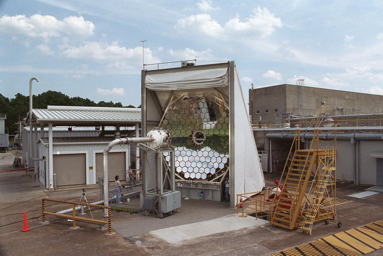
Researchers at the Marshall Space Flight Center (MSFC) have designed, fabricated and tested the first solar thermal engine, a non-chemical rocket engine that produces lower thrust but has better thrust efficiency than a chemical combustion engine. MSFC turned to solar thermal propulsion in the early 1990s due to its simplicity, safety, low cost, and commonality with other propulsion systems. Solar thermal propulsion works by acquiring and redirecting solar energy to heat a propellant. This photograph, taken at MSFC's Solar Thermal Propulsion Test Facility, shows a concentrator mirror, a combination of 144 mirrors forming this 18-ft diameter concentrator, and a vacuum chamber that houses the focal point. The 20- by 24-ft heliostat mirror (not shown in this photograph) has a dual-axis control that keeps a reflection of the sunlight on the 18-foot diameter concentrator mirror, which then focuses the sunlight to a 4-in focal point inside the vacuum chamber. The focal point has 10 kilowatts of intense solar power. As part of MSFC's Space Transportation Directorate, the Propulsion Research Center serves as a national resource for research of advanced, revolutionary propulsion technologies. The mission is to move the Nation's capabilities beyond the confines of conventional chemical propulsion into an era of aircraft-like access to Earth-orbit, rapid travel throughout the solar system, and exploration of interstellar space.
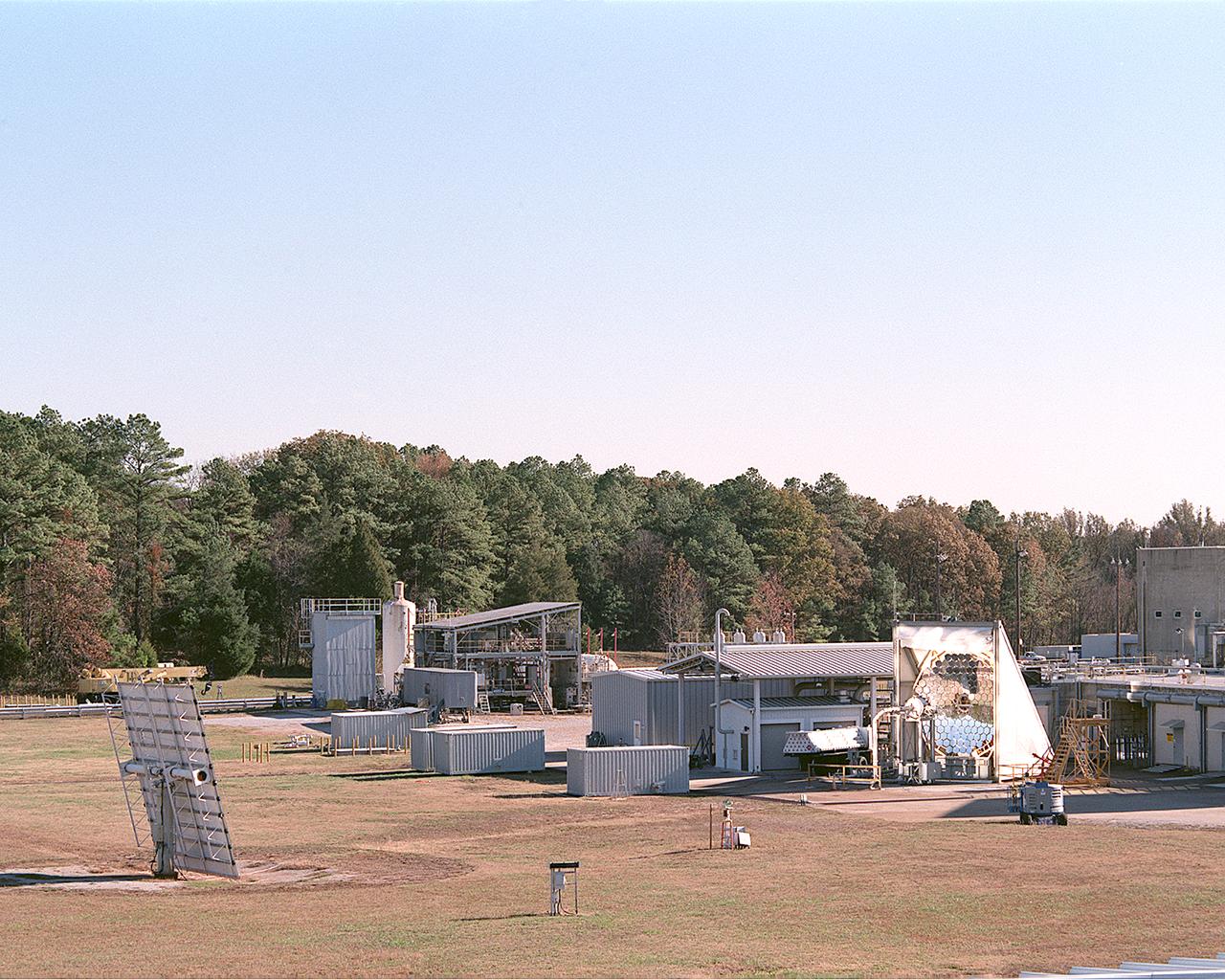
This photograph shows an overall view of the Solar Thermal Propulsion Test Facility at the Marshall Space Flight Center (MSFC). The 20-by 24-ft heliostat mirror, shown at the left, has dual-axis control that keeps a reflection of the sunlight on an 18-ft diameter concentrator mirror (right). The concentrator mirror then focuses the sunlight to a 4-in focal point inside the vacuum chamber, shown at the front of concentrator mirror. Researchers at MSFC have designed, fabricated, and tested the first solar thermal engine, a non-chemical rocket engine that produces lower thrust but has better thrust efficiency than chemical a combustion engine. MSFC turned to solar thermal propulsion in the early 1990s due to its simplicity, safety, low cost, and commonality with other propulsion systems. Solar thermal propulsion works by acquiring and redirecting solar energy to heat a propell nt. As part of MSFC's Space Transportation Directorate, the Propulsion Research Center serves as a national resource for research of advanced, revolutionary propulsion technologies. The mission is to move the Nation's capabilities beyond the confines of conventional chemical propulsion into an era of aircraft-like access to Earth-orbit, rapid travel throughout the solar system, and exploration of interstellar space.
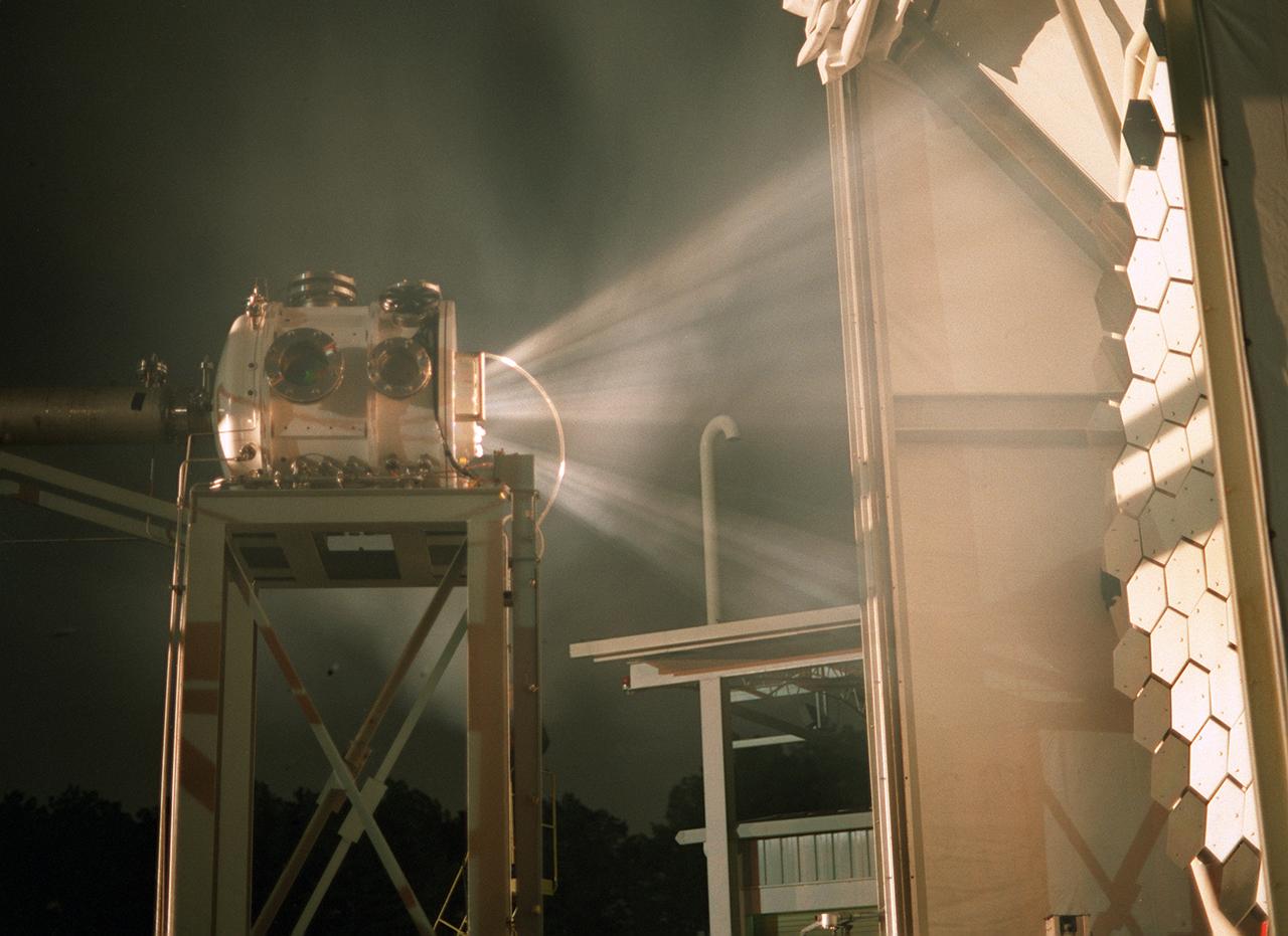
Researchers at the Marshall Space Flight Center (MSFC) have designed, fabricated, and tested the first solar thermal engine, a non-chemical rocket engine that produces lower thrust but has better thrust efficiency than a chemical combustion engine. MSFC turned to solar thermal propulsion in the early 1990s due to its simplicity, safety, low cost, and commonality with other propulsion systems. Solar thermal propulsion works by acquiring and redirecting solar energy to heat a propellant. The 20- by 24-ft heliostat mirror (not shown in this photograph) has a dual-axis control that keeps a reflection of the sunlight on the 18-ft diameter concentrator mirror, which then focuses the sunlight to a 4-in focal point inside the vacuum chamber. The focal point has 10 kilowatts of intense solar power. This image, taken during the test, depicts the light being concentrated into the focal point inside the vacuum chamber. As part of MSFC's Space Transportation Directorate, the Propulsion Research Center serves as a national resource for research of advanced, revolutionary propulsion technologies. The mission is to move the Nation's capabilities beyond the confines of conventional chemical propulsion into an era of aircraft-like access to Earth orbit, rapid travel throughout the solar system, and exploration of interstellar space.
NASA’s In-Space Propulsion Facility located at Neil Armstrong Test Facility in Sandusky Ohio is the world’s only high altitude test facility capable of full-scale rocket engine and launch vehicle system level tests. The facility supports mission profile thermal vacuum simulation and engine firing. The engine or vehicle can be exposed for indefinite periods to low ambient pressures, low-background temperatures, and dynamic solar heating, simulating the environment the hardware will encounter during orbital or interplanetary travel. Photo Credit: (NASA/Jordan Salkin)
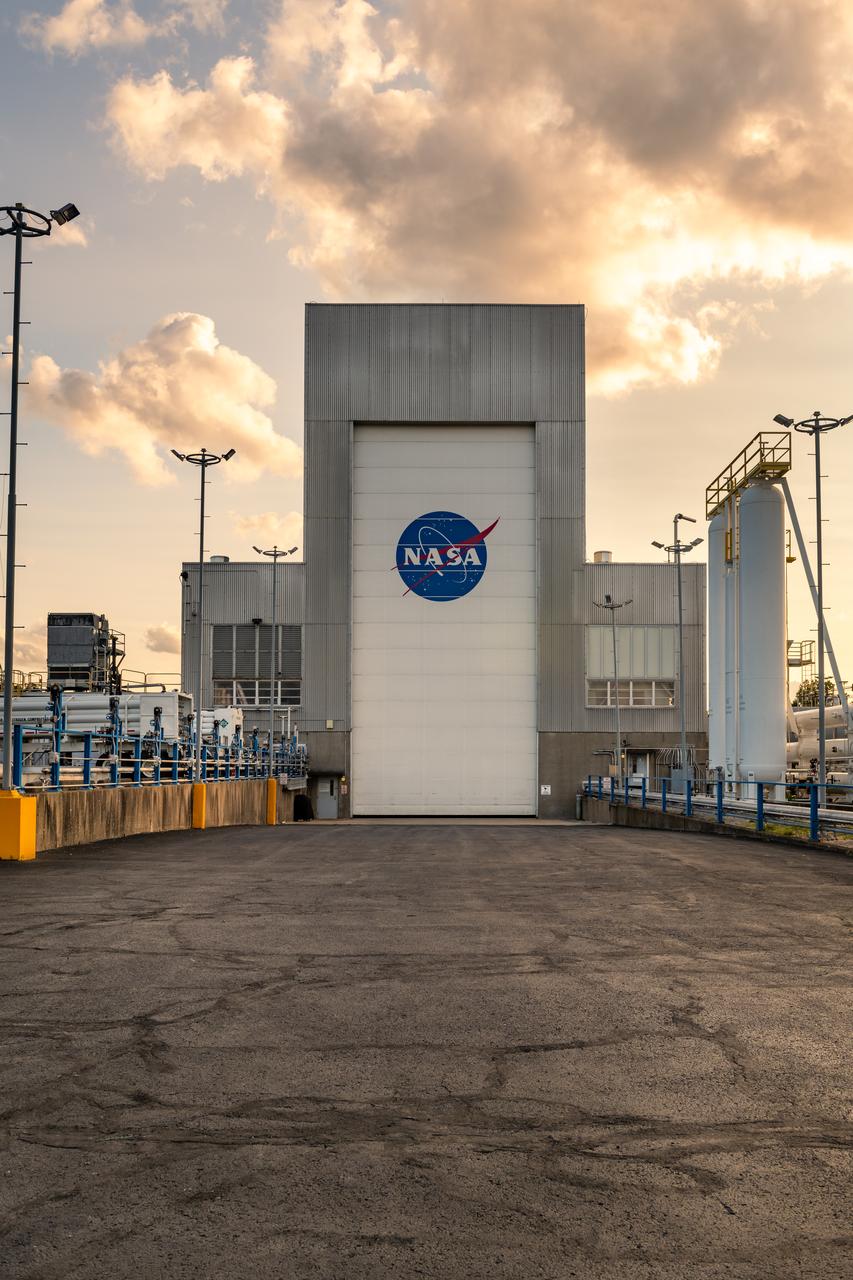
NASA’s In-Space Propulsion Facility located at Neil Armstrong Test Facility in Sandusky Ohio is the world’s only high altitude test facility capable of full-scale rocket engine and launch vehicle system level tests. The facility supports mission profile thermal vacuum simulation and engine firing. The engine or vehicle can be exposed for indefinite periods to low ambient pressures, low-background temperatures, and dynamic solar heating, simulating the environment the hardware will encounter during orbital or interplanetary travel. Photo Credit: (NASA/Jordan Salkin)
NASA’s In-Space Propulsion Facility located at Neil Armstrong Test Facility in Sandusky Ohio is the world’s only high altitude test facility capable of full-scale rocket engine and launch vehicle system level tests. The facility supports mission profile thermal vacuum simulation and engine firing. The engine or vehicle can be exposed for indefinite periods to low ambient pressures, low-background temperatures, and dynamic solar heating, simulating the environment the hardware will encounter during orbital or interplanetary travel. Photo Credit: (NASA/Jordan Salkin)
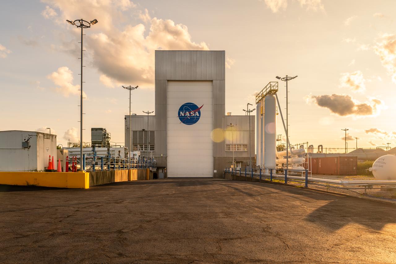
NASA’s In-Space Propulsion Facility located at Neil Armstrong Test Facility in Sandusky Ohio is the world’s only high altitude test facility capable of full-scale rocket engine and launch vehicle system level tests. The facility supports mission profile thermal vacuum simulation and engine firing. The engine or vehicle can be exposed for indefinite periods to low ambient pressures, low-background temperatures, and dynamic solar heating, simulating the environment the hardware will encounter during orbital or interplanetary travel. Photo Credit: (NASA/Jordan Salkin)
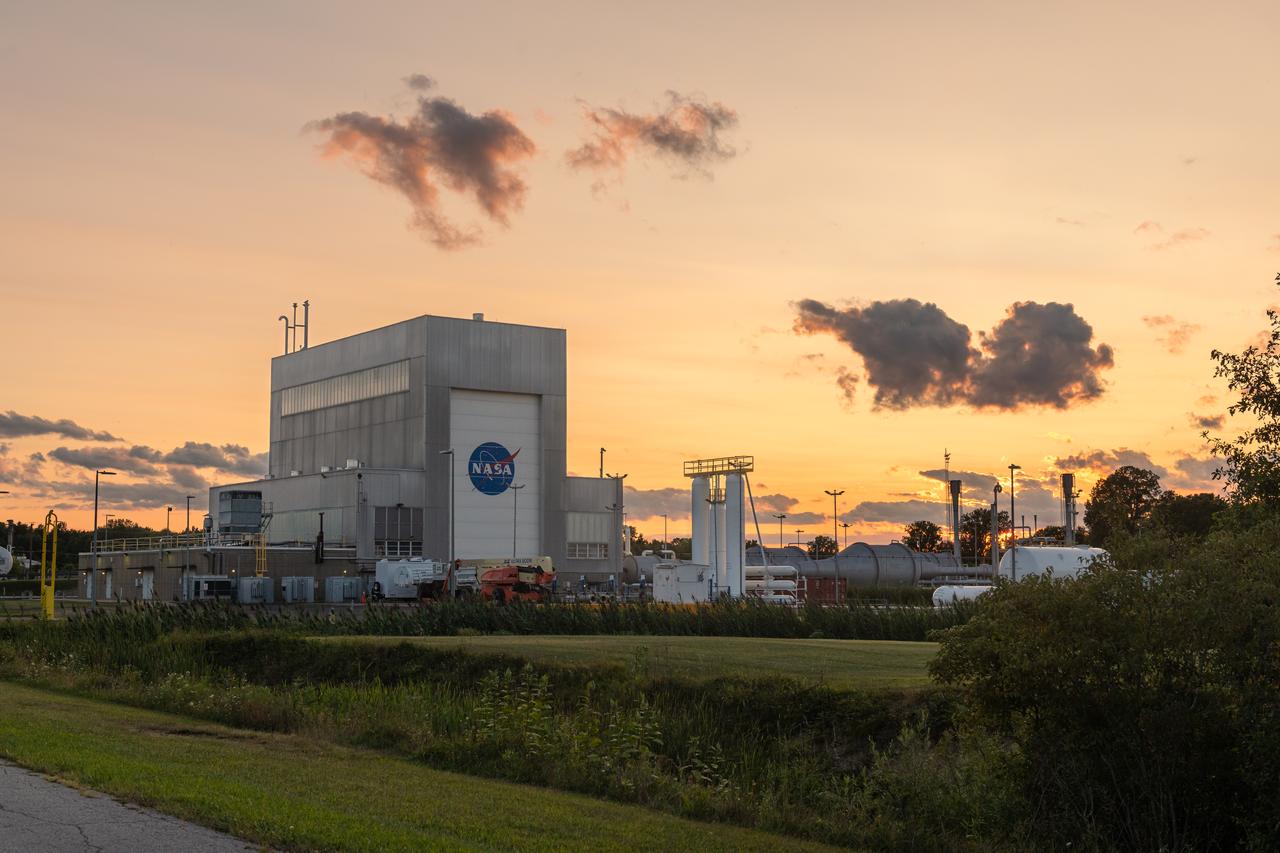
NASA’s In-Space Propulsion Facility located at Neil Armstrong Test Facility in Sandusky Ohio is the world’s only high altitude test facility capable of full-scale rocket engine and launch vehicle system level tests. The facility supports mission profile thermal vacuum simulation and engine firing. The engine or vehicle can be exposed for indefinite periods to low ambient pressures, low-background temperatures, and dynamic solar heating, simulating the environment the hardware will encounter during orbital or interplanetary travel. Photo Credit: (NASA/Jordan Salkin)
NASA’s In-Space Propulsion Facility located at Neil Armstrong Test Facility in Sandusky Ohio is the world’s only high altitude test facility capable of full-scale rocket engine and launch vehicle system level tests. The facility supports mission profile thermal vacuum simulation and engine firing. The engine or vehicle can be exposed for indefinite periods to low ambient pressures, low-background temperatures, and dynamic solar heating, simulating the environment the hardware will encounter during orbital or interplanetary travel. Photo Credit: (NASA/Jordan Salkin)
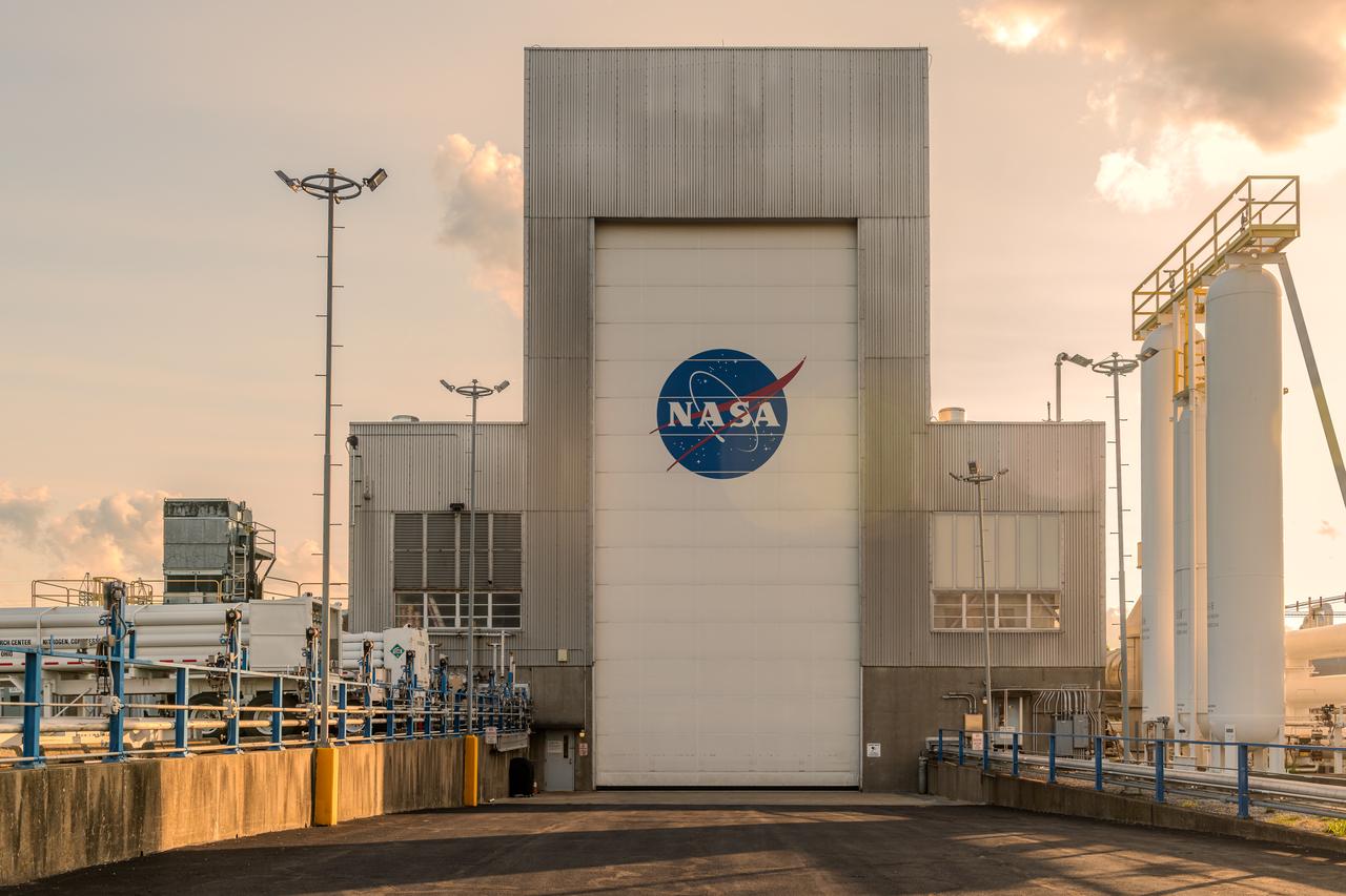
NASA’s In-Space Propulsion Facility located at Neil Armstrong Test Facility in Sandusky Ohio is the world’s only high altitude test facility capable of full-scale rocket engine and launch vehicle system level tests. The facility supports mission profile thermal vacuum simulation and engine firing. The engine or vehicle can be exposed for indefinite periods to low ambient pressures, low-background temperatures, and dynamic solar heating, simulating the environment the hardware will encounter during orbital or interplanetary travel. Photo Credit: (NASA/Jordan Salkin)
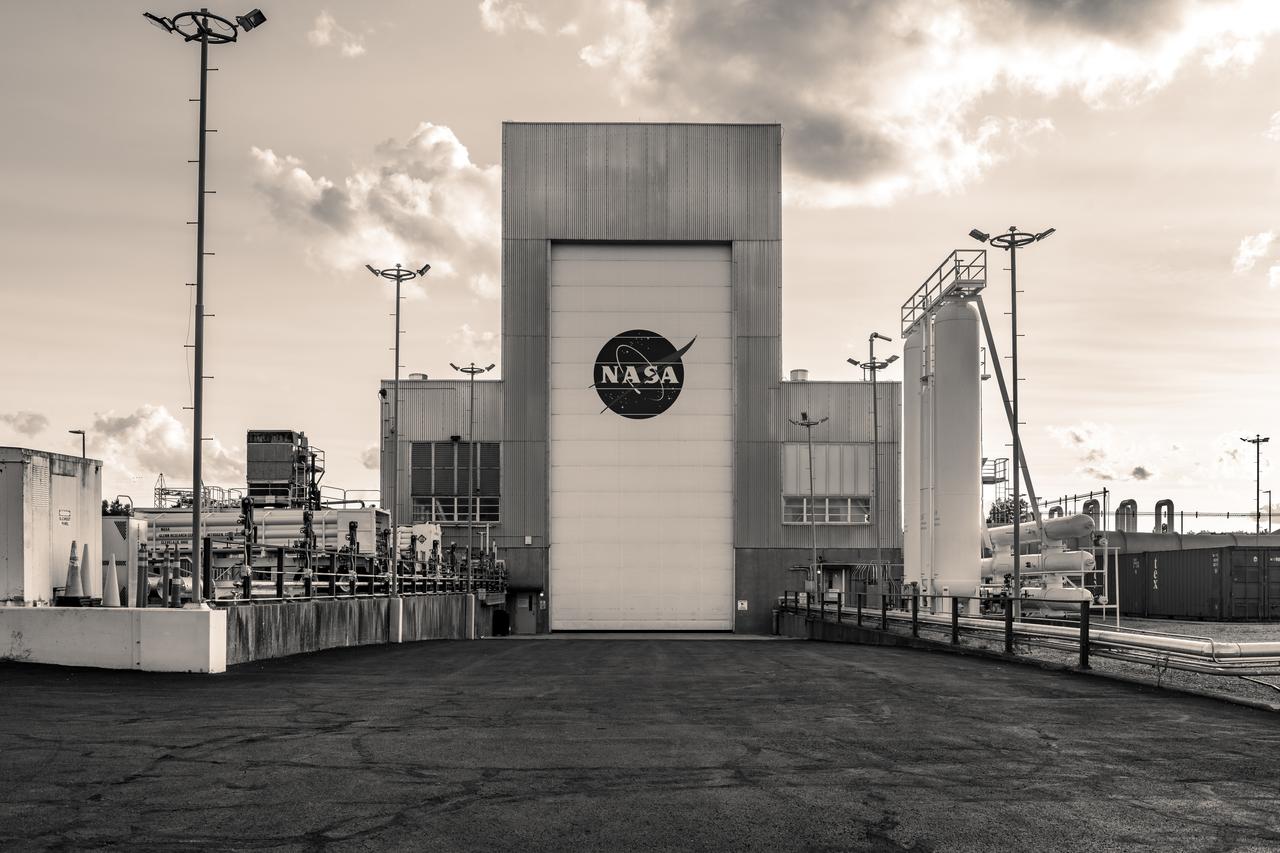
NASA’s In-Space Propulsion Facility located at Neil Armstrong Test Facility in Sandusky Ohio is the world’s only high altitude test facility capable of full-scale rocket engine and launch vehicle system level tests. The facility supports mission profile thermal vacuum simulation and engine firing. The engine or vehicle can be exposed for indefinite periods to low ambient pressures, low-background temperatures, and dynamic solar heating, simulating the environment the hardware will encounter during orbital or interplanetary travel. Photo Credit: (NASA/Jordan Salkin)
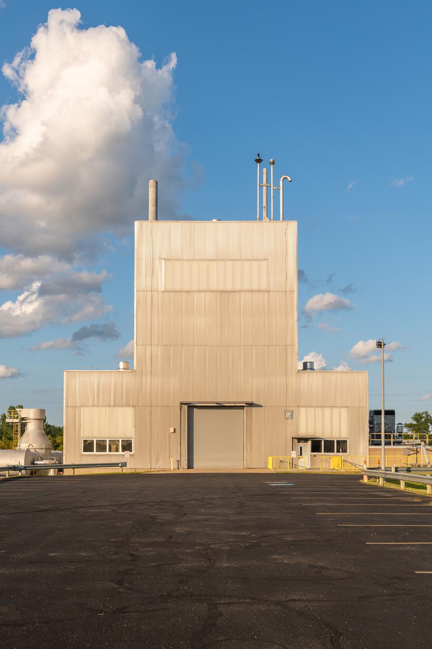
NASA’s In-Space Propulsion Facility located at Neil Armstrong Test Facility in Sandusky Ohio is the world’s only high altitude test facility capable of full-scale rocket engine and launch vehicle system level tests. The facility supports mission profile thermal vacuum simulation and engine firing. The engine or vehicle can be exposed for indefinite periods to low ambient pressures, low-background temperatures, and dynamic solar heating, simulating the environment the hardware will encounter during orbital or interplanetary travel. Photo Credit: (NASA/Jordan Salkin)
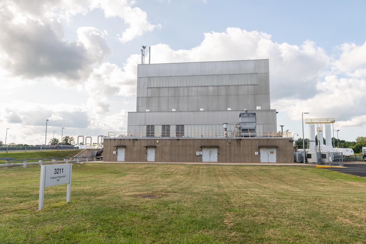
NASA’s In-Space Propulsion Facility located at Neil Armstrong Test Facility in Sandusky Ohio is the world’s only high altitude test facility capable of full-scale rocket engine and launch vehicle system level tests. The facility supports mission profile thermal vacuum simulation and engine firing. The engine or vehicle can be exposed for indefinite periods to low ambient pressures, low-background temperatures, and dynamic solar heating, simulating the environment the hardware will encounter during orbital or interplanetary travel. Photo Credit: (NASA/Jordan Salkin)
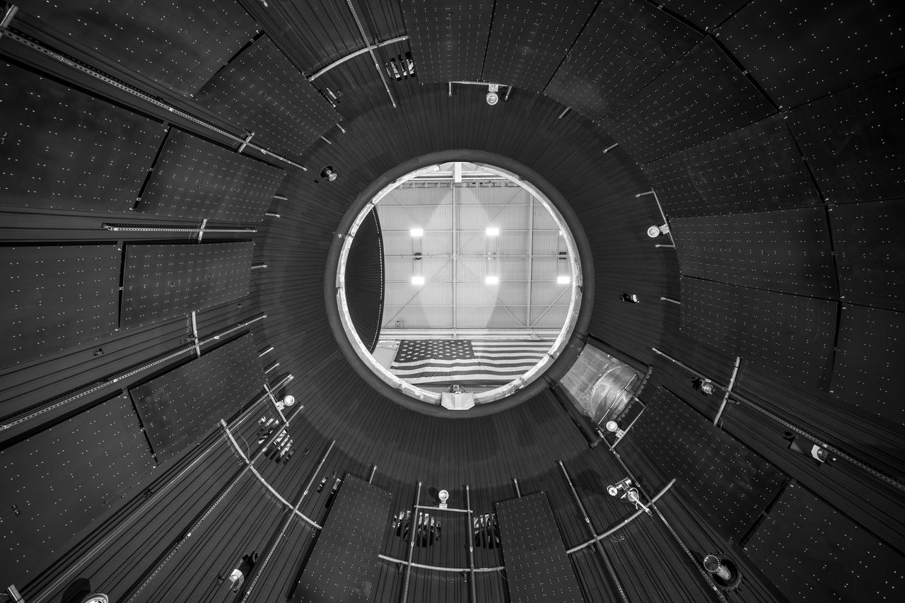
NASA’s In-Space Propulsion Facility located at Neil Armstrong Test Facility in Sandusky Ohio is the world’s only high altitude test facility capable of full-scale rocket engine and launch vehicle system level tests. The facility supports mission profile thermal vacuum simulation and engine firing. The engine or vehicle can be exposed for indefinite periods to low ambient pressures, low-background temperatures, and dynamic solar heating, simulating the environment the hardware will encounter during orbital or interplanetary travel. This is a view from inside the chamber looking up toward the American flag. Photo Credit: (NASA/Jordan Salkin)
In the Kennedy Space Center’s Press Site auditorium, on Friday, July 20, 2018, Betsy Congdon, Thermal Protection System engineer with the Johns Hopkins University Applied Physics Laboratory, right, demonstrates the ability of the Parker Solar Probe's heat shield to protect the spacecraft. The presentation for the media took place during a prelaunch mission briefing for the Parker Solar Probe mission. The Parker Solar Probe will lift off on a United Launch Alliance Delta IV Heavy rocket from Space Launch Complex 37 at Cape Canaveral Air Force Station in Florida. The spacecraft was built by Applied Physics Laboratory of Johns Hopkins University in Laurel in Maryland. The mission will perform the closest-ever observations of a star when it travels through the Sun's atmosphere, called the corona. The probe will rely on measurements and imaging to revolutionize understanding of the corona and the Sun-Earth connection.
An engineer working on NASA's Mars 2020 mission uses a solar intensity probe to measure and compare the amount of artificial sunlight that reaches different portions of the rover. To simulate the Sun's rays for the test, powerful xenon lamps several floors below the chamber were illuminated, their light directed onto a mirror at the top of the chamber and reflected down on the spacecraft. The data collected during this test will be used to confirm thermal models the team has generated regarding how the Sun's rays will interact with the 2020 rover while on the surface of Mars. The image was taken on Oct. 14, 2019, in the Space Simulator Facility at NASA's Jet Propulsion Laboratory in Pasadena, California. https://photojournal.jpl.nasa.gov/catalog/PIA23469
NASA’s Lewis Research Center conducted extensive research programs in the 1960s and 1970s to develop systems that provide electrical power in space. One system, the Brayton cycle engine, converted solar thermal energy into electrical power. This system operated on a closed-loop Brayton thermodynamic cycle. The Brayton system relied on this large mirror to collect radiation from the sun. The mirror concentrated the Sun's rays on a heat storage receiver which warmed the Brayton system’s working fluid, a helium-xenon gas mixture. The heated fluid powered the system’s generator which produced power. In the mid-1960s Lewis researchers constructed this 30-foot diameter prototype of a parabolic solar mirror for the Brayton cycle system. The mirror had to be rigid, impervious to micrometeorite strikes, and lightweight. This mirror was comprised of twelve 1-inch thick magnesium plate sections that were coated with aluminum. The mirror could be compactly broken into its sections for launch.
NASA engineer Acey Herrera recently checked out copper test wires inside the thermal shield of the Mid-Infrared Instrument, known as MIRI, that will fly aboard NASA's James Webb Space Telescope. The shield is designed to protect the vital MIRI instrument from excess heat. At the time of the photo, the thermal shield was about to go through rigorous environmental testing to ensure it can perform properly in the extreme cold temperatures that it will encounter in space. Herrera is working in a thermal vacuum chamber at NASA's Goddard Space Flight Center in Greenbelt, Md. As the MIRI shield lead, Herrera along with a thermal engineer and cryo-engineer verify that the shield is ready for testing. On the Webb telescope, the pioneering camera and spectrometer that comprise the MIRI instrument sit inside the Integrated Science Instrument Module flight structure, that holds Webb's four instruments and their electronic systems during launch and operations. Read more: <a href="http://1.usa.gov/15I0wrS" rel="nofollow">1.usa.gov/15I0wrS</a> Credit: NASA/Chris Gunn <b><a href="http://www.nasa.gov/audience/formedia/features/MP_Photo_Guidelines.html" rel="nofollow">NASA image use policy.</a></b> <b><a href="http://www.nasa.gov/centers/goddard/home/index.html" rel="nofollow">NASA Goddard Space Flight Center</a></b> enables NASA’s mission through four scientific endeavors: Earth Science, Heliophysics, Solar System Exploration, and Astrophysics. Goddard plays a leading role in NASA’s accomplishments by contributing compelling scientific knowledge to advance the Agency’s mission. <b>Follow us on <a href="http://twitter.com/NASA_GoddardPix" rel="nofollow">Twitter</a></b> <b>Like us on <a href="http://www.facebook.com/pages/Greenbelt-MD/NASA-Goddard/395013845897?ref=tsd" rel="nofollow">Facebook</a></b> <b>Find us on <a href="http://instagram.com/nasagoddard?vm=grid" rel="nofollow">Instagram</a></b>
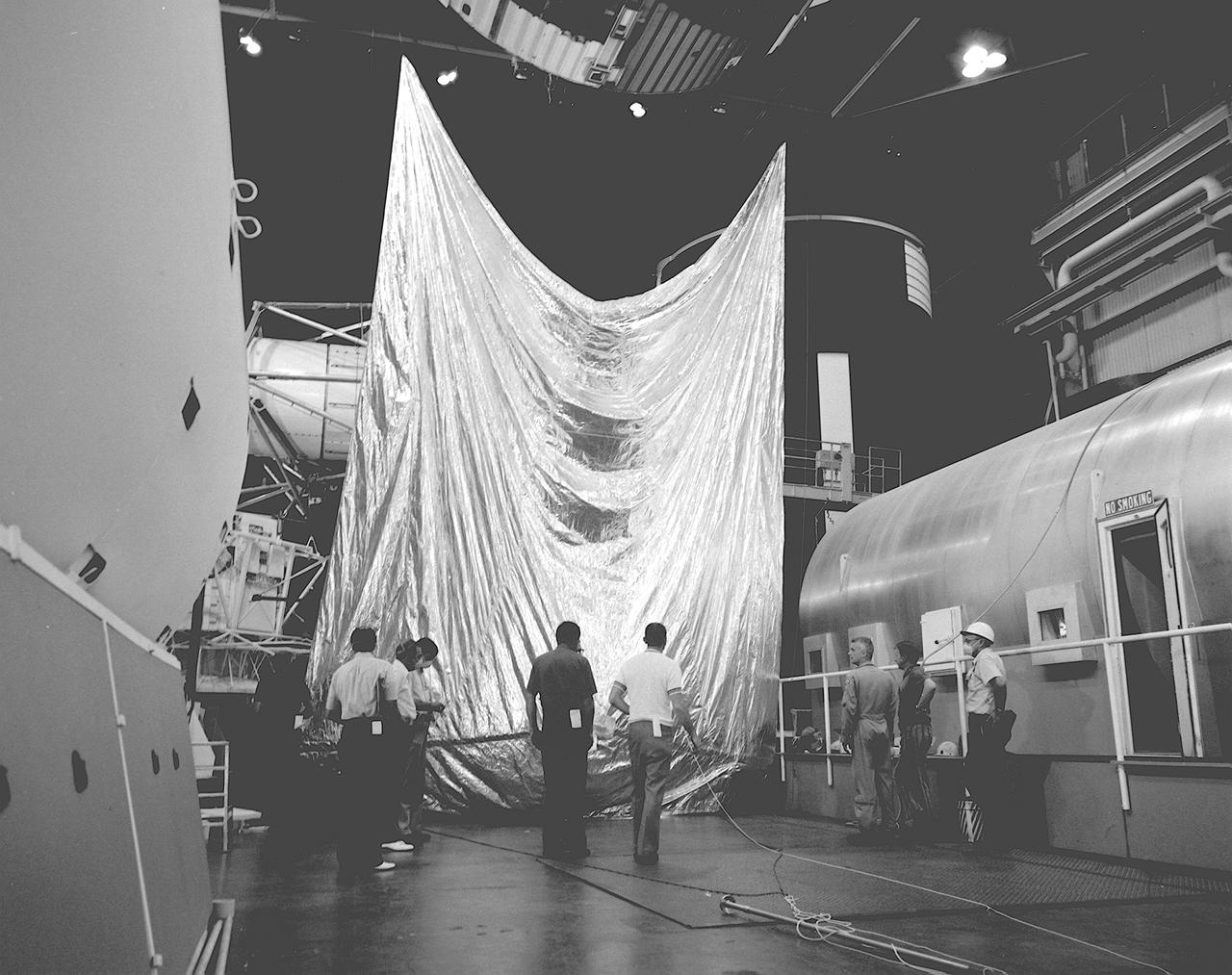
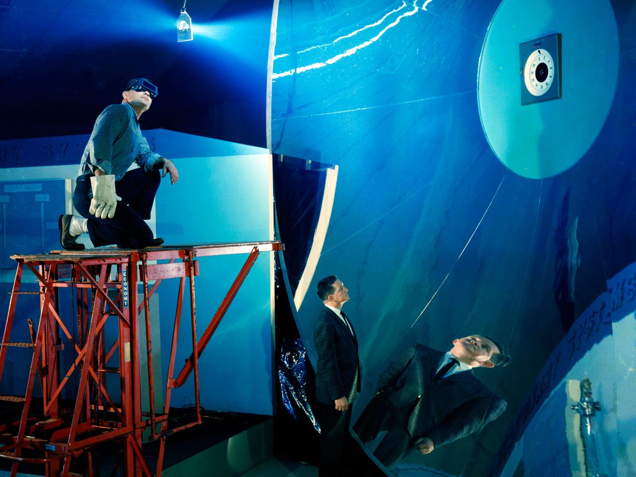
Engineers from the Marshall Space Flight Center (MSFC) and its contractors were testing the twin-pole sunshade at the Skylab mockup in the MSFC Building 4619. The Skylab Orbital Workshop (OWS) lost its thermal protection shield during launch on May 14, 1963. Without the heat shield, the temperature inside the OWS became dangerously high, rendering the workshop uninhabitable and threatened deterioration of the interior insulation and adhesive. Engineers from the MSFC, its contractors, and NASA persornel at other centers worked day and night for several days to develop the way to save the Skylab OWS. Eventually, they developed, tested, rehearsed, and approved three repair options. These options included a parasol sunshade and a twin-pole sunshade to restore the temperature inside the workshop, and a set of metal cutting tools to free the jammed solar panel.
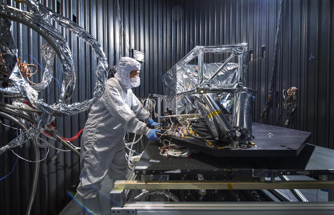
Engineers install multilayer insulation (MLI) on the Mass Spectrometer Observing Lunar Operations (MSolo) instrument inside Kennedy Space Center’s Space Station Processing Facility on Oct. 20, 2022. The activity is in preparation for the Polar Resources Ice Mining Experiment-1 (PRIME-1) mission, which will be the first in-situ resource utilization demonstration on the Moon. MLI protects the instrument from thermal temperature extremes, helping to insulate at cold temperatures and to cool at higher temperatures when solar lighting conditions or lunar infrared reflects onto the instrument. Researchers and engineers are preparing MSolo instruments to launch on four robotic missions as part of NASA’s Commercial Lunar Payload Services – commercial deliveries beginning in 2023 that will perform science experiments, test technologies, and demonstrate capabilities to help NASA explore the Moon and prepare for crewed missions to the lunar surface.

Engineers install multilayer insulation (MLI) on the Mass Spectrometer Observing Lunar Operations (MSolo) instrument inside Kennedy Space Center’s Space Station Processing Facility on Oct. 20, 2022. The activity is in preparation for the Polar Resources Ice Mining Experiment-1 (PRIME-1) mission, which will be the first in-situ resource utilization demonstration on the Moon. MLI protects the instrument from thermal temperature extremes, helping to insulate at cold temperatures and to cool at higher temperatures when solar lighting conditions or lunar infrared reflects onto the instrument. Researchers and engineers are preparing MSolo instruments to launch on four robotic missions as part of NASA’s Commercial Lunar Payload Services – commercial deliveries beginning in 2023 that will perform science experiments, test technologies, and demonstrate capabilities to help NASA explore the Moon and prepare for crewed missions to the lunar surface.
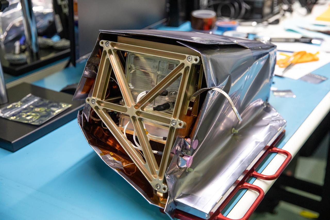
Engineers install multilayer insulation (MLI) on the Mass Spectrometer Observing Lunar Operations (MSolo) instrument inside Kennedy Space Center’s Space Station Processing Facility on Oct. 20, 2022. The activity is in preparation for the Polar Resources Ice Mining Experiment-1 (PRIME-1) mission, which will be the first in-situ resource utilization demonstration on the Moon. MLI protects the instrument from thermal temperature extremes, helping to insulate at cold temperatures and to cool at higher temperatures when solar lighting conditions or lunar infrared reflects onto the instrument. Researchers and engineers are preparing MSolo instruments to launch on four robotic missions as part of NASA’s Commercial Lunar Payload Services – commercial deliveries beginning in 2023 that will perform science experiments, test technologies, and demonstrate capabilities to help NASA explore the Moon and prepare for crewed missions to the lunar surface.
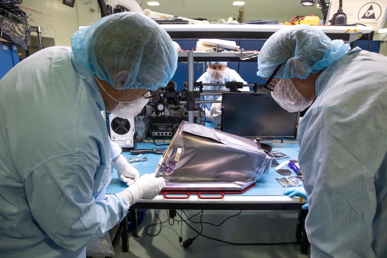
Engineers install multilayer insulation (MLI) on the Mass Spectrometer Observing Lunar Operations (MSolo) instrument inside Kennedy Space Center’s Space Station Processing Facility on Oct. 20, 2022. The activity is in preparation for the Polar Resources Ice Mining Experiment-1 (PRIME-1) mission, which will be the first in-situ resource utilization demonstration on the Moon. MLI protects the instrument from thermal temperature extremes, helping to insulate at cold temperatures and to cool at higher temperatures when solar lighting conditions or lunar infrared reflects onto the instrument. Researchers and engineers are preparing MSolo instruments to launch on four robotic missions as part of NASA’s Commercial Lunar Payload Services – commercial deliveries beginning in 2023 that will perform science experiments, test technologies, and demonstrate capabilities to help NASA explore the Moon and prepare for crewed missions to the lunar surface.
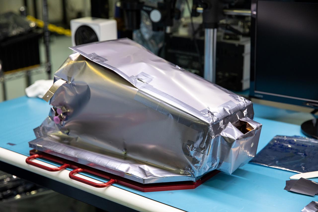
Engineers install multilayer insulation (MLI) on the Mass Spectrometer Observing Lunar Operations (MSolo) instrument inside Kennedy Space Center’s Space Station Processing Facility on Oct. 20, 2022. The activity is in preparation for the Polar Resources Ice Mining Experiment-1 (PRIME-1) mission, which will be the first in-situ resource utilization demonstration on the Moon. MLI protects the instrument from thermal temperature extremes, helping to insulate at cold temperatures and to cool at higher temperatures when solar lighting conditions or lunar infrared reflects onto the instrument. Researchers and engineers are preparing MSolo instruments to launch on four robotic missions as part of NASA’s Commercial Lunar Payload Services – commercial deliveries beginning in 2023 that will perform science experiments, test technologies, and demonstrate capabilities to help NASA explore the Moon and prepare for crewed missions to the lunar surface.
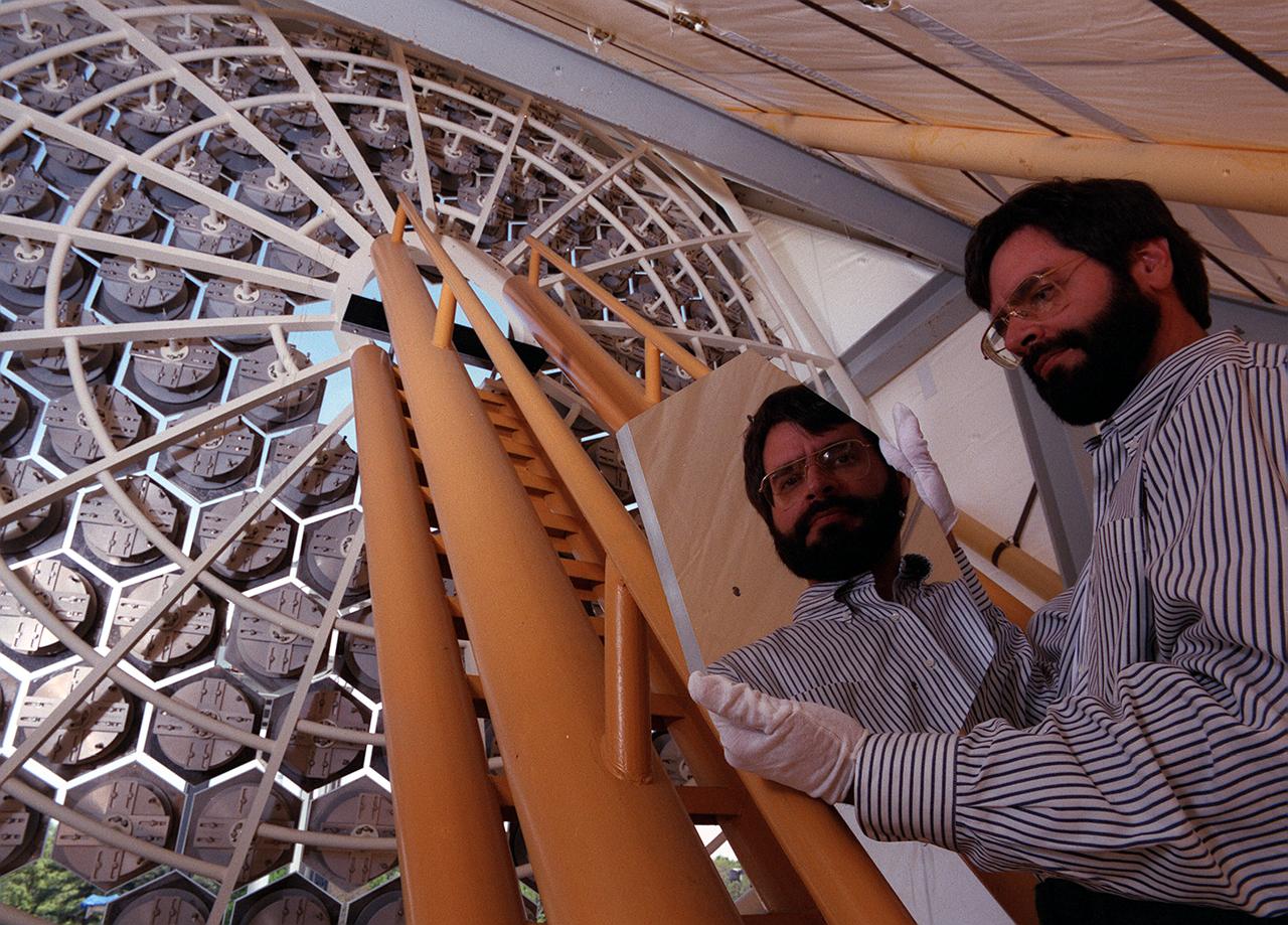
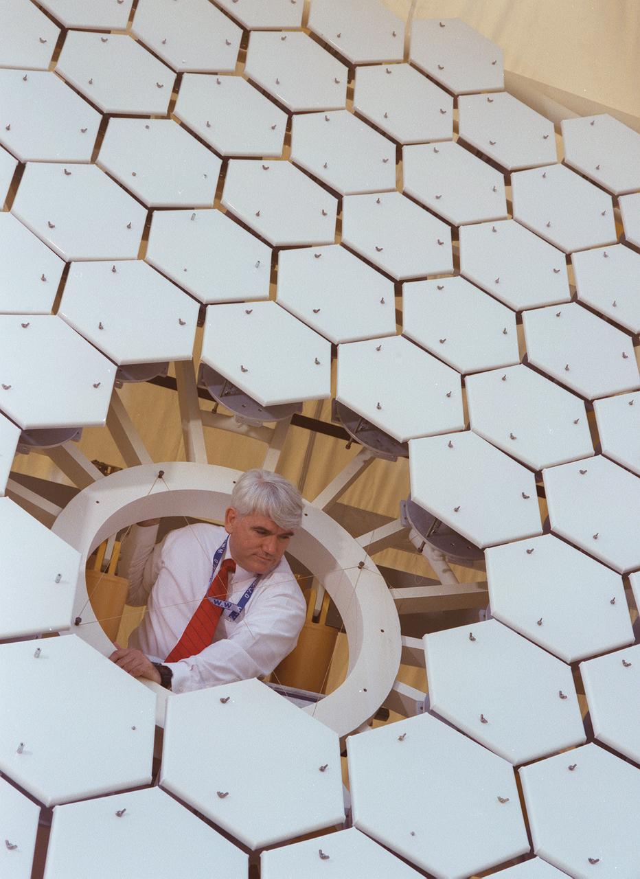
NASA's Space Optics Manufacturing Technology Center has been working to expand our view of the universe via sophisticated new telescopes. The Optics Center's goal is to develop low-cost, advanced space optics technologies for the NASA program in the 21st century, including the long-term goal of imaging Earth-like planets in distant solar systems. A segmented array of mirrors was designed by the Space Optics Manufacturing Technology Center for solar the concentrator test stand at the Marshall Space Flight Center (MSFC) for powering solar thermal propulsion engines. Each hexagon mirror has a spherical surface to approximate a parabolic concentrator when combined into the entire 18-foot diameter array. The aluminum mirrors were polished with a diamond turning machine, that creates a glass-like reflective finish on metal. The precision fabrication machinery at the Space Optics Manufacturing Technology Center at MSFC can polish specialized optical elements to a world class quality of smoothness. This image shows optics physicist, Vince Huegele, examining one of the 144-segment hexagonal mirrors of the 18-foot diameter array at the MSFC solar concentrator test stand.
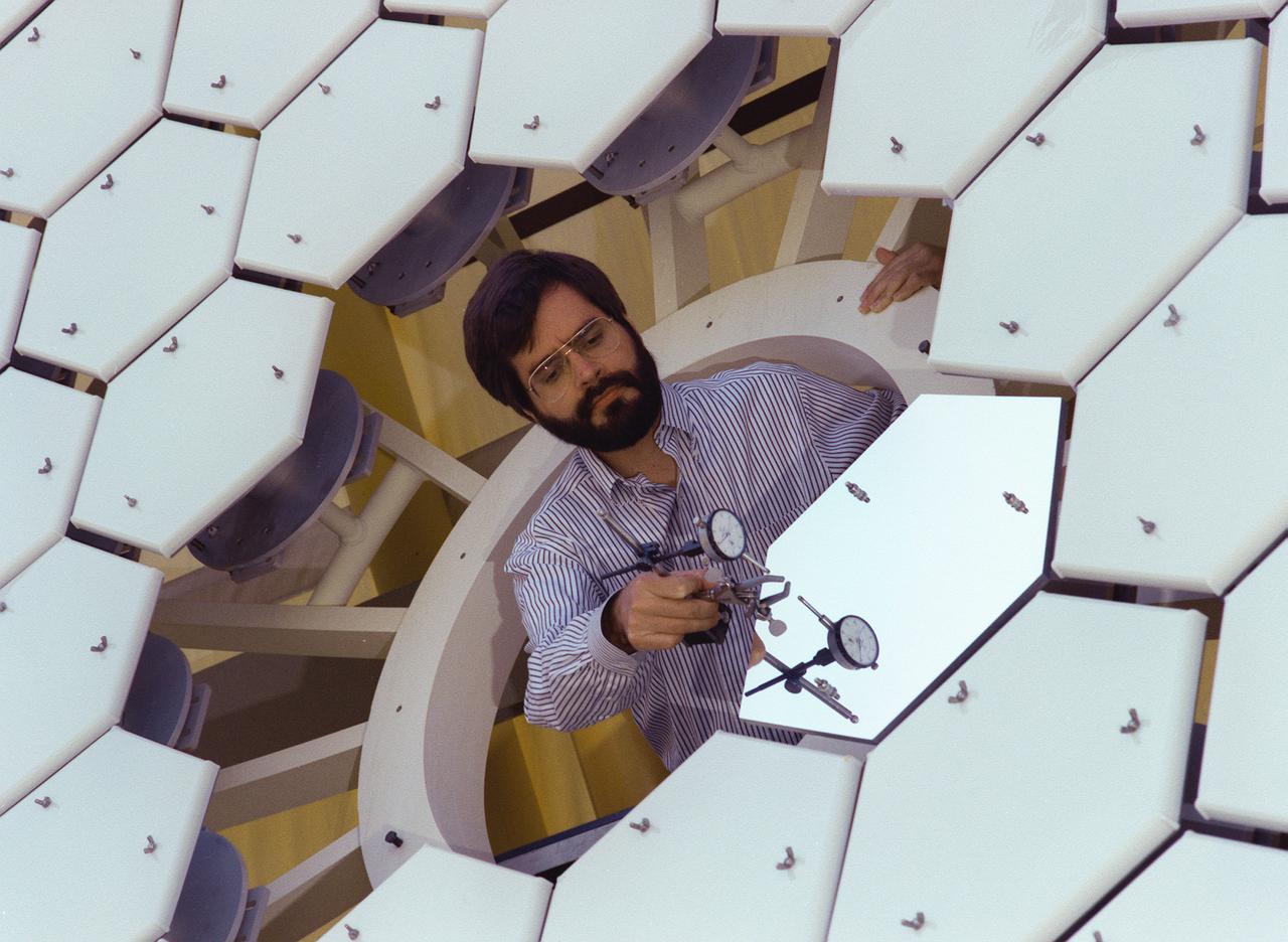
NASA's Space Optics Manufacturing Technology Center has been working to expand our view of the universe via sophisticated new telescopes. The Optics Center's goal is to develop low-cost, advanced space optics technologies for the NASA program in the 21st century, including the long-term goal of imaging Earth-like planets in distant solar systems. A segmented array of mirrors was designed by the Space Optics Manufacturing Technology Center for the solar concentrator test stand at the Marshall Space Flight Center (MSFC) for powering solar thermal propulsion engines. Each hexagon mirror has a spherical surface to approximate a parabolic concentrator when combined into the entire 18-foot diameter array. The aluminum mirrors were polished with a diamond turning machine that creates a glass-like reflective finish on metal. The precision fabrication machinery at the Space Optics Manufacturing Technology Center at MSFC can polish specialized optical elements to a world class quality of smoothness. This image shows optics physicist, Vince Huegele, examining one of the 144-segment hexagonal mirrors of the 18-foot diameter array at the MSFC solar concentrator test stand.
KENNEDY SPACE CENTER, FLA. -- Deep Space 1 rests on its work platform after being fitted with thermal insulation. The reflective insulation is designed to protect the spacecraft as this side faces the sun. At either side of the spacecraft are its solar wings, folded for launch. When fully extended, the wings measure 38.6 feet from tip to tip. The first flight in NASA's New Millennium Program, Deep Space 1 is designed to validate 12 new technologies for scientific space missions of the next century. Onboard experiments include a solar-powered ion propulsion engine and software that tracks celestial bodies so the spacecraft can make its own navigation decisions without the intervention of ground controllers. The ion propulsion engine is the first non-chemical propulsion to be used as the primary means of propelling a spacecraft. Deep Space 1 will complete most of its mission objectives within the first two months, but may also do a flyby of a near-Earth asteroid, 1992 KD, in July 1999. Deep Space 1 will be launched aboard a Boeing Delta 7326 rocket from Launch Pad 17A, Cape Canaveral Air Station, in October. Delta II rockets are medium capacity expendable launch vehicles derived from the Delta family of rockets built and launched since 1960. Since then there have been more than 245 Delta launches
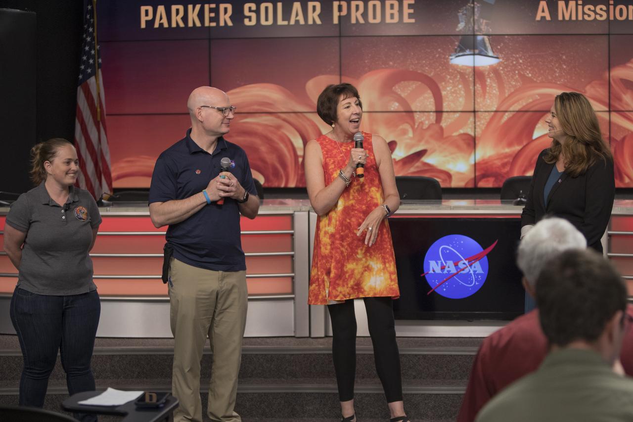
In the Kennedy Space Center’s Press Site auditorium, on Friday, July 20, 2018, agency and mission leaders speak to members of the media during a prelaunch briefing for the Parker Solar Probe mission. From left are: Betsy Congdon, Thermal Protection System engineer with Johns Hopkins Applied Physics Laboratory, Alex Young, solar scientist at NASA's Goddard Space Flight Center in Greenbelt, Maryland, Nicky Fox, project scientist with the Johns Hopkins University APL, and Karen Fox of NASA Communications. The Parker Solar Probe will lift off on a United Launch Alliance Delta IV Heavy rocket from Space Launch Complex 37 at Cape Canaveral Air Force Station in Florida. The spacecraft was built by Applied Physics Laboratory of Johns Hopkins University in Laurel in Maryland. The mission will perform the closest-ever observations of a star when it travels through the Sun's atmosphere, called the corona. The probe will rely on measurements and imaging to revolutionize understanding of the corona and the Sun-Earth connection.
An engineer prepares a small rover – part of NASA's CADRE (Cooperative Autonomous Distributed Robotic Exploration) technology demonstration that's headed to the Moon – for testing in a thermal vacuum chamber at the agency's Jet Propulsion Laboratory in Southern California in October 2023. Slated to arrive at the Moon in 2024 as part of NASA's CLPS (Commercial Lunar Payload Services) initiative, CADRE is designed to demonstrate that multiple robots can cooperate and explore together autonomously – without direct input from human mission controllers. A trio of the miniature solar-powered rovers, each about the size of a carry-on suitcase, will explore the Moon as a team, communicating via radio with each other and a base station aboard a lunar lander. By taking simultaneous measurements from multiple locations, CADRE will also demonstrate how multirobot missions can record data impossible for a single robot to achieve – a tantalizing prospect for future missions. The rover being tested is the first flight model to be completed. Thermal vacuum testing simulates the harsh environment the rovers will face on the journey to the Moon and on the lunar surface: All the air is pumped out of the chamber and the temperature is cycled to high and low extremes. https://photojournal.jpl.nasa.gov/catalog/PIA25669
Engineers work with the Integrated Science Instrument Module for the James Webb Space Telescope inside the thermal vacuum chamber at NASA's Goddard Space Flight Center in Greenbelt, Md. The ISIM and the ISIM System Integration Fixture that holds the ISIM Electronics Compartment was recently lifted inside the chamber for its first thermal vacuum test. In this image one of the ISIM's many protective blanket layers is pulled back. The blankets will be removed during testing. Image credit: NASA/Chris Gunn <b><a href="http://www.nasa.gov/audience/formedia/features/MP_Photo_Guidelines.html" rel="nofollow">NASA image use policy.</a></b> <b><a href="http://www.nasa.gov/centers/goddard/home/index.html" rel="nofollow">NASA Goddard Space Flight Center</a></b> enables NASA’s mission through four scientific endeavors: Earth Science, Heliophysics, Solar System Exploration, and Astrophysics. Goddard plays a leading role in NASA’s accomplishments by contributing compelling scientific knowledge to advance the Agency’s mission. <b>Follow us on <a href="http://twitter.com/NASA_GoddardPix" rel="nofollow">Twitter</a></b> <b>Like us on <a href="http://www.facebook.com/pages/Greenbelt-MD/NASA-Goddard/395013845897?ref=tsd" rel="nofollow">Facebook</a></b> <b>Find us on <a href="http://instagram.com/nasagoddard?vm=grid" rel="nofollow">Instagram</a></b>
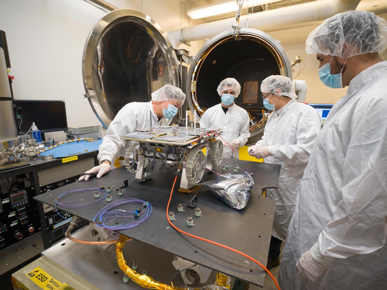
Engineers prepare a small rover – part of NASA's CADRE (Cooperative Autonomous Distributed Robotic Exploration) technology demonstration that's headed to the Moon – for testing in the thermal vacuum chamber behind them at the agency's Jet Propulsion Laboratory in Southern California in October 2023. Slated to arrive at the Moon in 2024 as part of NASA's CLPS (Commercial Lunar Payload Services) initiative, CADRE is designed to demonstrate that multiple robots can cooperate and explore together autonomously – without direct input from human mission controllers. A trio of the miniature solar-powered rovers, each about the size of a carry-on suitcase, will explore the Moon as a team, communicating via radio with each other and a base station aboard a lunar lander. By taking simultaneous measurements from multiple locations, CADRE will also demonstrate how multirobot missions can record data impossible for a single robot to achieve – a tantalizing prospect for future missions. The rover being tested is the first flight model to be completed. Thermal vacuum testing simulates the harsh environment the rovers will face on the journey to the Moon and on the lunar surface: All the air is pumped out of the chamber and the temperature is cycled to high and low extremes. https://photojournal.jpl.nasa.gov/catalog/PIA25670

An overhead glimpse inside the thermal vacuum chamber at NASA's Goddard Space Flight Center in Greenbelt, Md., as engineers ready the James Webb Space Telescope's Integrated Science Instrument Module, just lowered into the chamber for its first thermal vacuum test. The ISIM and the ISIM System Integration Fixture that holds the ISIM Electronics Compartment is completely covered in protective blankets to shield it from contamination. Image credit: NASA/Chris Gunn <b><a href="http://www.nasa.gov/audience/formedia/features/MP_Photo_Guidelines.html" rel="nofollow">NASA image use policy.</a></b> <b><a href="http://www.nasa.gov/centers/goddard/home/index.html" rel="nofollow">NASA Goddard Space Flight Center</a></b> enables NASA’s mission through four scientific endeavors: Earth Science, Heliophysics, Solar System Exploration, and Astrophysics. Goddard plays a leading role in NASA’s accomplishments by contributing compelling scientific knowledge to advance the Agency’s mission. <b>Follow us on <a href="http://twitter.com/NASA_GoddardPix" rel="nofollow">Twitter</a></b> <b>Like us on <a href="http://www.facebook.com/pages/Greenbelt-MD/NASA-Goddard/395013845897?ref=tsd" rel="nofollow">Facebook</a></b> <b>Find us on <a href="http://instagram.com/nasagoddard?vm=grid" rel="nofollow">Instagram</a></b>
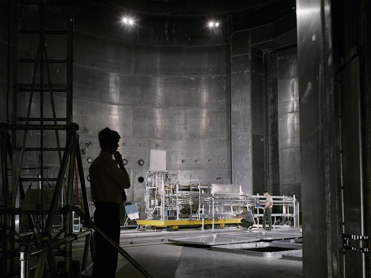
Set up of a Brayton Cycle Power System test in the Space Power Facility’s massive vacuum chamber at the National Aeronautics and Space Administration’s (NASA) Plum Brook Station in Sandusky, Ohio. The $28.4-million facility, which began operations in 1969, is the largest high vacuum chamber ever built. The chamber is 100 feet in diameter and 120 feet high. It can produce a vacuum deep enough to simulate the conditions at 300 miles altitude. The Space Power Facility was originally designed to test nuclear-power sources for spacecraft, but it was never used for that purpose. The Space Power Facility was first used to test a 15 to 20-kilowatt Brayton Cycle Power System for space applications. Three different methods of simulating solar heat were employed during the tests. Lewis researchers studied the Brayton power system extensively in the 1960s and 1970s. The Brayton engine converted solar thermal energy into electrical power. The system operated on a closed-loop Brayton thermodynamic cycle with a helium-xenon gas mixture as its working fluid. A space radiator was designed to serve as the system’s waste heat rejecter. The radiator was later installed in the vacuum chamber and tested in a simulated space environment to determine its effect on the power conversion system. The Brayton system was subjected to simulated orbits with 62 minutes of sun and 34 minutes of shade.
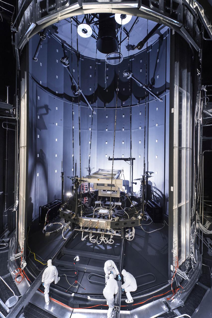
NASA's Psyche spacecraft is seen in early 2022 on its way to the vacuum chamber at the agency's Jet Propulsion Laboratory in Southern California. Thermal-vacuum (TVAC) testing is part of a regimen of environmental tests that are crucial for ensuring the spacecraft can survive the extreme conditions of launch and outer space. The orbiter will travel 1.5 billion miles (2.4 billion kilometers) to its target in the main asteroid belt, a metal-rich asteroid also called Psyche. Scientists believe the asteroid could be part or all of the iron-rich interior of an early planetary building block that was stripped of its outer rocky shell in the early days of the solar system. Over 18 days of TVAC testing, engineers exposed the spacecraft to the coldest and warmest conditions it will experience in flight, to prove that it is capable of regulating its own temperature. All of the air was sucked out of the chamber to replicate the airless vacuum of space. This test ensures that the spacecraft can survive the vacuum of space, and it helps engineers see how the spacecraft heats and cools itself without the movement of air to help it regulate temperature. Psyche is set to launch in August 2022. https://photojournal.jpl.nasa.gov/catalog/PIA25231
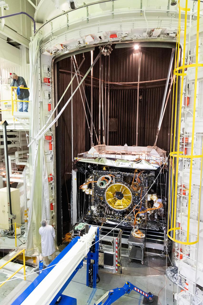
NASA's Psyche spacecraft is seen in early 2022 as it is placed in the 85-foot-tall, 25-foot-wide (26-meter-by-8-meter) ultra-sturdy vacuum chamber at the agency's Jet Propulsion Laboratory in Southern California. Thermal-vacuum (TVAC) testing is part of a regimen of environmental tests that are crucial for ensuring the spacecraft can survive the extreme conditions of launch and outer space. The orbiter will travel 1.5 billion miles (2.4 billion kilometers) to its target in the main asteroid belt, a metal-rich asteroid also called Psyche. Scientists believe the asteroid could be part or all of the iron-rich interior of an early planetary building block that was stripped of its outer rocky shell in the early days of the solar system. Over 18 days of TVAC testing, engineers exposed the spacecraft to the coldest and warmest conditions it will experience in flight, to prove that it is capable of regulating its own temperature. All of the air was sucked out of the chamber to replicate the airless vacuum of space. This test ensures that the spacecraft can survive the vacuum of space, and it helps engineers see how the spacecraft heats and cools itself without the movement of air to help it regulate temperature. Psyche is set to launch in August 2022. https://photojournal.jpl.nasa.gov/catalog/PIA25232
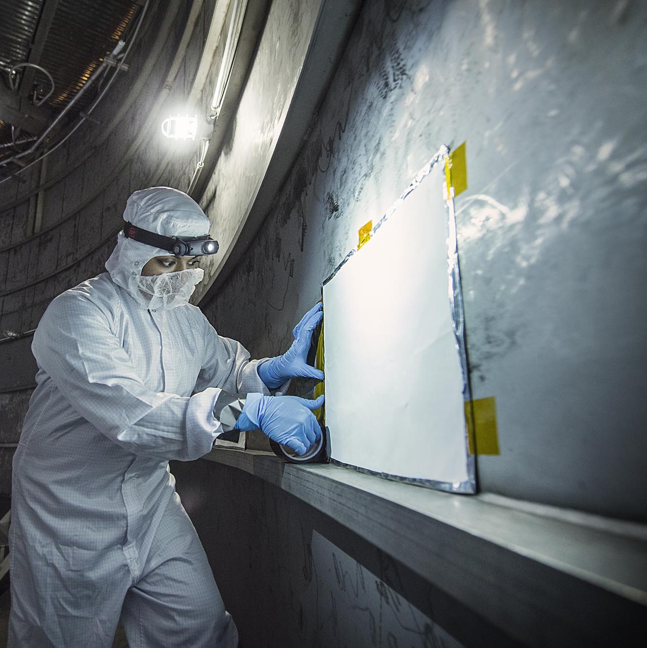
Contamination from organic molecules can harm delicate instruments and engineers are taking special care at NASA to prevent that from affecting the James Webb Space Telescope (and all satellites and instruments). Recently, Nithin Abraham, a Thermal Coatings Engineer placed Molecular Adsorber Coating or "MAC" panels in the giant chamber where the Webb telescope will be tested. This contamination can occur through a process when a vapor or odor is emitted by a substance. This is called "outgassing." The "new car smell" is an example of that, and is unhealthy for people and sensitive satellite instruments. So, NASA engineers have created a new way to protect those instruments from the damaging effects of contamination coming from outgassing. "The Molecular Adsorber Coating (MAC) is a NASA Goddard coatings technology that was developed to adsorb or entrap outgassed molecular contaminants for spaceflight applications," said Nithin Abraham, Thermal Coatings Engineer at NASA's Goddard Space Flight Center in Greenbelt, Maryland. MAC is currently serving as an innovative contamination mitigation tool for Chamber A operations at NASA Johnson Space Center in Houston, Texas. MAC can be used to keep outgassing from coming in from outside areas or to capture outgassing directly from hardware, components, and within instrument cavities. In this case, MAC is helping by capturing outgassed contaminants outside the test chamber from affecting the Webb components. MAC is expected to capture the outgassed contaminants that exist in the space of the vacuum chamber (not from the Webb components). Credit: NASA/GoddardChris Gunn Read more: <a href="http://www.nasa.gov/feature/goddard/nasa-technology-protects-webb-telescope-from-contamination" rel="nofollow">www.nasa.gov/feature/goddard/nasa-technology-protects-web...</a> <b><a href="http://www.nasa.gov/audience/formedia/features/MP_Photo_Guidelines.html" rel="nofollow">NASA image use policy.</a></b> <b><a href="http://www.nasa.gov/centers/goddard/home/index.html" rel="nofollow">NASA Goddard Space Flight Center</a></b> enables NASA’s mission through four scientific endeavors: Earth Science, Heliophysics, Solar System Exploration, and Astrophysics. Goddard plays a leading role in NASA’s accomplishments by contributing compelling scientific knowledge to advance the Agency’s mission. <b>Follow us on <a href="http://twitter.com/NASAGoddardPix" rel="nofollow">Twitter</a></b> <b>Like us on <a href="http://www.facebook.com/pages/Greenbelt-MD/NASA-Goddard/395013845897?ref=tsd" rel="nofollow">Facebook</a></b> <b>Find us on <a href="http://instagrid.me/nasagoddard/?vm=grid" rel="nofollow">Instagram</a></b>
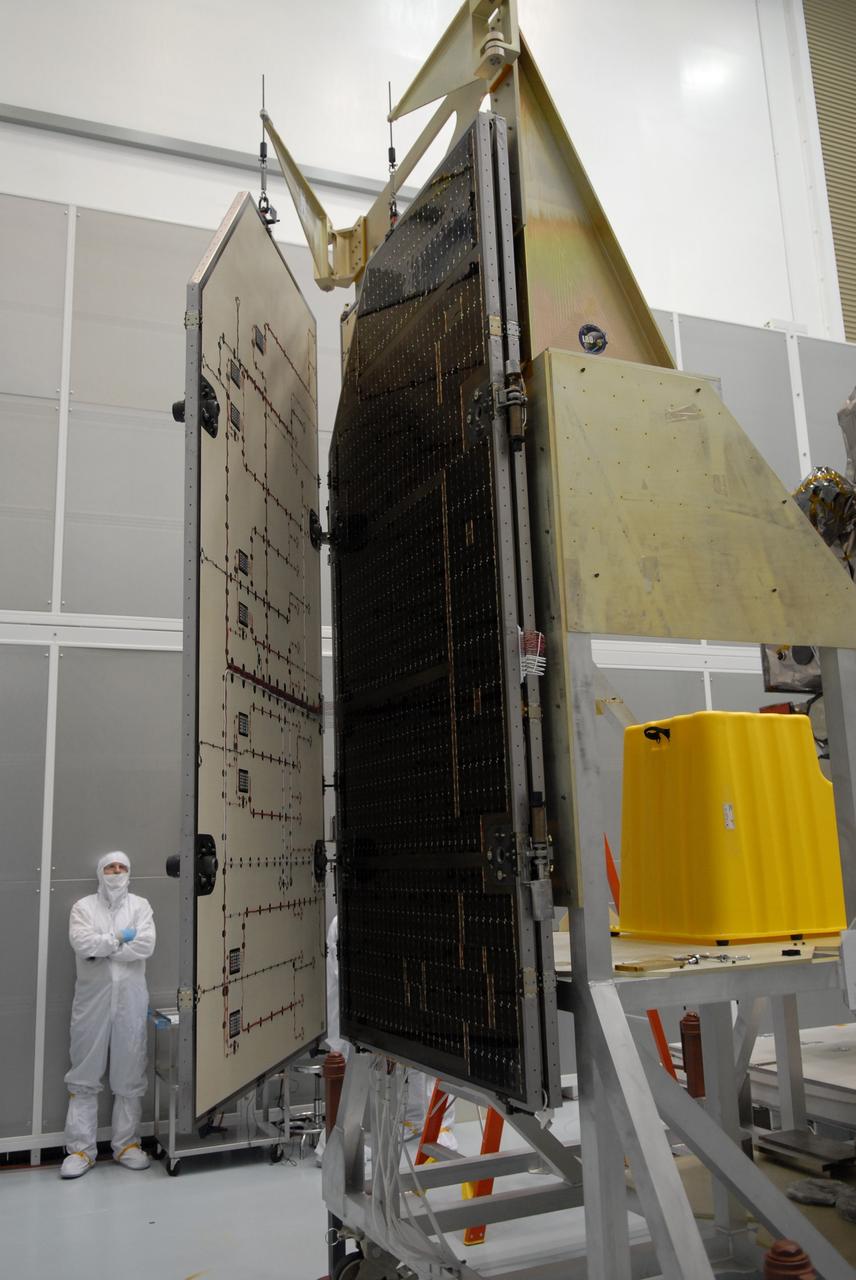
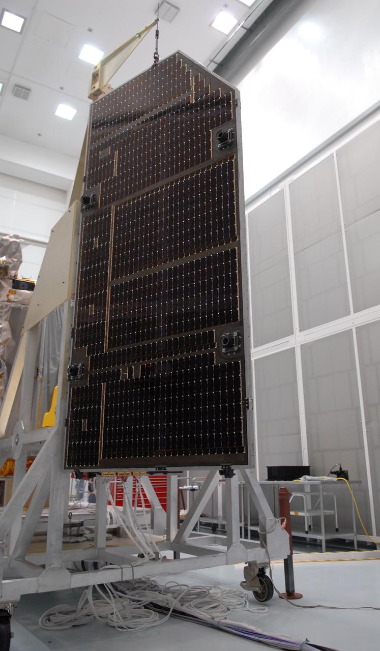
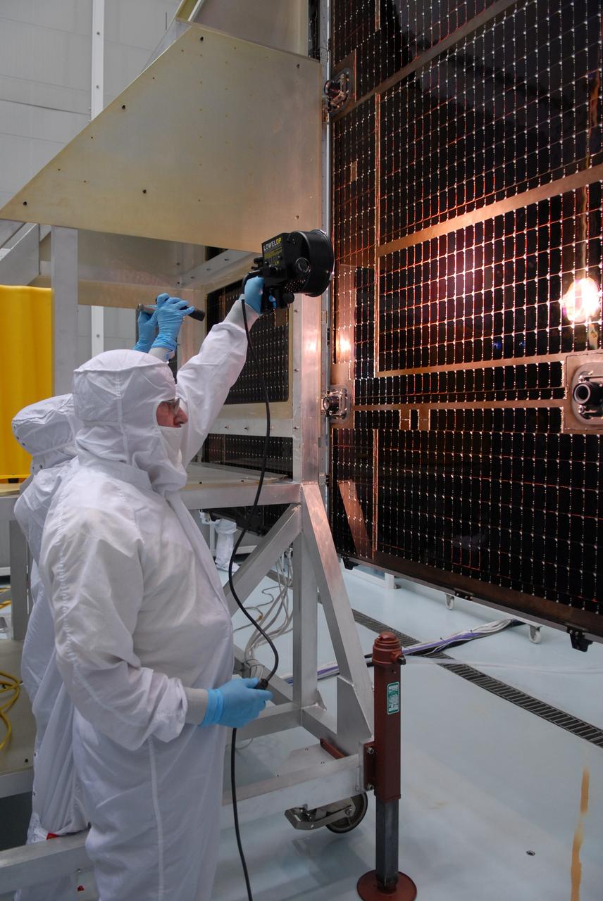
CAPE CANAVERAL, Fla. – The solar arrays for NASA's Lunar Reconnaissance Orbiter, or LRO, are inspected at the Astrotech processing facility in Titusville, Fla. The spacecraft was built by engineers at Goddard Space Flight Center, where it recently completed two months of tests in a thermal vacuum chamber. The orbiter will carry seven instruments to provide scientists with detailed maps of the lunar surface and enhance our understanding of the moon's topography, lighting conditions, mineralogical composition and natural resources. Information gleaned from LRO will be used to select safe landing sites, determine locations for future lunar outposts and help mitigate radiation dangers to astronauts. The polar regions of the moon are the main focus of the mission because continuous access to sunlight may be possible and water ice may exist in permanently shadowed areas of the poles. Accompanying LRO on its journey to the moon will be the Lunar Crater Observation and Sensing Satellite, or LCROSS, a mission that will impact the lunar surface in its search for water ice. Launch of LRO/LCROSS is targeted for April 24. Photo credit: NASA/Jack Pfaller
CAPE CANAVERAL, Fla. – A technician inspects the solar arrays for NASA's Lunar Reconnaissance Orbiter, or LRO, at the Astrotech processing facility in Titusville, Fla. The spacecraft was built by engineers at Goddard Space Flight Center, where it recently completed two months of tests in a thermal vacuum chamber. The orbiter will carry seven instruments to provide scientists with detailed maps of the lunar surface and enhance our understanding of the moon's topography, lighting conditions, mineralogical composition and natural resources. Information gleaned from LRO will be used to select safe landing sites, determine locations for future lunar outposts and help mitigate radiation dangers to astronauts. The polar regions of the moon are the main focus of the mission because continuous access to sunlight may be possible and water ice may exist in permanently shadowed areas of the poles. Accompanying LRO on its journey to the moon will be the Lunar Crater Observation and Sensing Satellite, or LCROSS, a mission that will impact the lunar surface in its search for water ice. Launch of LRO/LCROSS is targeted for April 24. Photo credit: NASA/Jack Pfaller
CAPE CANAVERAL, Fla. – A technician inspects the solar arrays for NASA's Lunar Reconnaissance Orbiter, or LRO, at the Astrotech processing facility in Titusville, Fla. The spacecraft was built by engineers at Goddard Space Flight Center, where it recently completed two months of tests in a thermal vacuum chamber. The orbiter will carry seven instruments to provide scientists with detailed maps of the lunar surface and enhance our understanding of the moon's topography, lighting conditions, mineralogical composition and natural resources. Information gleaned from LRO will be used to select safe landing sites, determine locations for future lunar outposts and help mitigate radiation dangers to astronauts. The polar regions of the moon are the main focus of the mission because continuous access to sunlight may be possible and water ice may exist in permanently shadowed areas of the poles. Accompanying LRO on its journey to the moon will be the Lunar Crater Observation and Sensing Satellite, or LCROSS, a mission that will impact the lunar surface in its search for water ice. Launch of LRO/LCROSS is targeted for April 24. Photo credit: NASA/Jack Pfaller
CAPE CANAVERAL, Fla. – Inspection is under way of the solar arrays for NASA's Lunar Reconnaissance Orbiter, or LRO, at the Astrotech processing facility in Titusville, Fla. The spacecraft was built by engineers at Goddard Space Flight Center, where it recently completed two months of tests in a thermal vacuum chamber. The orbiter will carry seven instruments to provide scientists with detailed maps of the lunar surface and enhance our understanding of the moon's topography, lighting conditions, mineralogical composition and natural resources. Information gleaned from LRO will be used to select safe landing sites, determine locations for future lunar outposts and help mitigate radiation dangers to astronauts. The polar regions of the moon are the main focus of the mission because continuous access to sunlight may be possible and water ice may exist in permanently shadowed areas of the poles. Accompanying LRO on its journey to the moon will be the Lunar Crater Observation and Sensing Satellite, or LCROSS, a mission that will impact the lunar surface in its search for water ice. Launch of LRO/LCROSS is targeted for April 24. Photo credit: NASA/Jack Pfaller
CAPE CANAVERAL, Fla. – Technicians check out the solar arrays for NASA's Lunar Reconnaissance Orbiter, or LRO, at the Astrotech processing facility in Titusville, Fla. The spacecraft was built by engineers at Goddard Space Flight Center, where it recently completed two months of tests in a thermal vacuum chamber. The orbiter will carry seven instruments to provide scientists with detailed maps of the lunar surface and enhance our understanding of the moon's topography, lighting conditions, mineralogical composition and natural resources. Information gleaned from LRO will be used to select safe landing sites, determine locations for future lunar outposts and help mitigate radiation dangers to astronauts. The polar regions of the moon are the main focus of the mission because continuous access to sunlight may be possible and water ice may exist in permanently shadowed areas of the poles. Accompanying LRO on its journey to the moon will be the Lunar Crater Observation and Sensing Satellite, or LCROSS, a mission that will impact the lunar surface in its search for water ice. Launch of LRO/LCROSS is targeted for April 24. Photo credit: NASA/Jack Pfaller
CAPE CANAVERAL, Fla. – NASA Associate Administrator Robert Lightfoot, center, tours the Thermal Protection System Facility, or TPSF, during a visit to NASA's Kennedy Space Center in Florida. From left are Kennedy Director Bob Cabana, Lightfoot, and Martin Boyd, TPSF manager with Jacobs Technologies, briefing his guests on the production of TPS tile for NASA's new Orion spacecraft. NASA's FY2014 budget proposal includes a plan to robotically capture a small near-Earth asteroid and redirect it safely to a stable orbit in the Earth-moon system where astronauts can visit and explore it. Performing these elements for the proposed asteroid initiative integrates the best of NASA's science, technology and human exploration capabilities and draws on the innovation of America's brightest scientists and engineers. It uses current and developing capabilities to find both large asteroids that pose a hazard to Earth and small asteroids that could be candidates for the initiative, accelerates our technology development activities in high-powered solar electric propulsion and takes advantage of our hard work on the Space Launch System rocket and Orion spacecraft, helping to keep NASA on target to reach the President's goal of sending humans to Mars in the 2030s. Photo credit: NASA_Jim Grossmann
Dressed in a clean room suit, NASA photographer Desiree Stover shines a light on the Space Environment Simulator's Integration Frame inside the thermal vacuum chamber at NASA's Goddard Space Flight Center in Greenbelt, Md. Shortly after, the chamber was closed up and engineers used this frame to enclose and help cryogenic (cold) test the heart of the James Webb Space Telescope, the Integrated Science Instrument Module. Credit: NASA/Goddard/Chris Gunn <b><a href="http://www.nasa.gov/audience/formedia/features/MP_Photo_Guidelines.html" rel="nofollow">NASA image use policy.</a></b> <b><a href="http://www.nasa.gov/centers/goddard/home/index.html" rel="nofollow">NASA Goddard Space Flight Center</a></b> enables NASA’s mission through four scientific endeavors: Earth Science, Heliophysics, Solar System Exploration, and Astrophysics. Goddard plays a leading role in NASA’s accomplishments by contributing compelling scientific knowledge to advance the Agency’s mission. <b>Follow us on <a href="http://twitter.com/NASA_GoddardPix" rel="nofollow">Twitter</a></b> <b>Like us on <a href="http://www.facebook.com/pages/Greenbelt-MD/NASA-Goddard/395013845897?ref=tsd" rel="nofollow">Facebook</a></b> <b>Find us on <a href="http://instagram.com/nasagoddard?vm=grid" rel="nofollow">Instagram</a></b>
CAPE CANAVERAL, Fla. – Technicians inspect the solar arrays for NASA's Lunar Reconnaissance Orbiter, or LRO, at the Astrotech processing facility in Titusville, Fla. The spacecraft was built by engineers at Goddard Space Flight Center, where it recently completed two months of tests in a thermal vacuum chamber. The orbiter will carry seven instruments to provide scientists with detailed maps of the lunar surface and enhance our understanding of the moon's topography, lighting conditions, mineralogical composition and natural resources. Information gleaned from LRO will be used to select safe landing sites, determine locations for future lunar outposts and help mitigate radiation dangers to astronauts. The polar regions of the moon are the main focus of the mission because continuous access to sunlight may be possible and water ice may exist in permanently shadowed areas of the poles. Accompanying LRO on its journey to the moon will be the Lunar Crater Observation and Sensing Satellite, or LCROSS, a mission that will impact the lunar surface in its search for water ice. Launch of LRO/LCROSS is targeted for April 24. Photo credit: NASA/Jack Pfaller
CAPE CANAVERAL, Fla. – Inspection begins of the solar arrays for NASA's Lunar Reconnaissance Orbiter, or LRO, at the Astrotech processing facility in Titusville, Fla. The spacecraft was built by engineers at Goddard Space Flight Center, where it recently completed two months of tests in a thermal vacuum chamber. The orbiter will carry seven instruments to provide scientists with detailed maps of the lunar surface and enhance our understanding of the moon's topography, lighting conditions, mineralogical composition and natural resources. Information gleaned from LRO will be used to select safe landing sites, determine locations for future lunar outposts and help mitigate radiation dangers to astronauts. The polar regions of the moon are the main focus of the mission because continuous access to sunlight may be possible and water ice may exist in permanently shadowed areas of the poles. Accompanying LRO on its journey to the moon will be the Lunar Crater Observation and Sensing Satellite, or LCROSS, a mission that will impact the lunar surface in its search for water ice. Launch of LRO/LCROSS is targeted for April 24. Photo credit: NASA/Jack Pfaller
CAPE CANAVERAL, Fla. – Technicians check out the solar arrays for NASA's Lunar Reconnaissance Orbiter, or LRO, at the Astrotech processing facility in Titusville, Fla. The spacecraft was built by engineers at Goddard Space Flight Center, where it recently completed two months of tests in a thermal vacuum chamber. The orbiter will carry seven instruments to provide scientists with detailed maps of the lunar surface and enhance our understanding of the moon's topography, lighting conditions, mineralogical composition and natural resources. Information gleaned from LRO will be used to select safe landing sites, determine locations for future lunar outposts and help mitigate radiation dangers to astronauts. The polar regions of the moon are the main focus of the mission because continuous access to sunlight may be possible and water ice may exist in permanently shadowed areas of the poles. Accompanying LRO on its journey to the moon will be the Lunar Crater Observation and Sensing Satellite, or LCROSS, a mission that will impact the lunar surface in its search for water ice. Launch of LRO/LCROSS is targeted for April 24. Photo credit: NASA/Jack Pfaller
KENNEDY SPACE CENTER, FLA. -- After covering the bulk of Deep Space 1 in thermal insulating blankets, workers in the Payload Hazardous Servicing Facility lift it from its work platform before moving it onto its transporter (behind workers at left). Deep Space 1 is being moved to the Defense Satellite Communications System Processing Facility (DPF), Cape Canaveral Air Station, for testing. At either side of the spacecraft are its solar wings, folded for launch. When fully extended, the wings measure 38.6 feet from tip to tip. The first flight in NASA's New Millennium Program, Deep Space 1 is designed to validate 12 new technologies for scientific space missions of the next century. Onboard experiments include a solar-powered ion propulsion engine and software that tracks celestial bodies so the spacecraft can make its own navigation decisions without the intervention of ground controllers. The ion propulsion engine is the first non-chemical propulsion to be used as the primary means of propelling a spacecraft. Deep Space 1 will complete most of its mission objectives within the first two months, but may also do a flyby of a near-Earth asteroid, 1992 KD, in July 1999. Deep Space 1 will be launched aboard a Boeing Delta 7326 rocket from Launch Pad 17A, Cape Canaveral Air Station, in October. Delta II rockets are medium capacity expendable launch vehicles derived from the Delta family of rockets built and launched since 1960. Since then there have been more than 245 Delta launches
KENNEDY SPACE CENTER, FLA. -- Deep Space 1 rests on its work platform after being fitted with thermal insulation. The dark insulation is designed to protect the side of the spacecraft that faces away from the sun. At either side of the spacecraft are its solar wings, folded for launch. When fully extended, the wings measure 38.6 feet from tip to tip. The first flight in NASA's New Millennium Program, Deep Space 1 is designed to validate 12 new technologies for scientific space missions of the next century. Onboard experiments include a solar-powered ion propulsion engine and software that tracks celestial bodies so the spacecraft can make its own navigation decisions without the intervention of ground controllers. The ion propulsion engine is the first non-chemical propulsion to be used as the primary means of propelling a spacecraft. Deep Space 1 will complete most of its mission objectives within the first two months, but may also do a flyby of a near-Earth asteroid, 1992 KD, in July 1999. Deep Space 1 will be launched aboard a Boeing Delta 7326 rocket from Launch Pad 17A, Cape Canaveral Air Station, in October. Delta II rockets are medium capacity expendable launch vehicles derived from the Delta family of rockets built and launched since 1960. Since then there have been more than 245 Delta launches
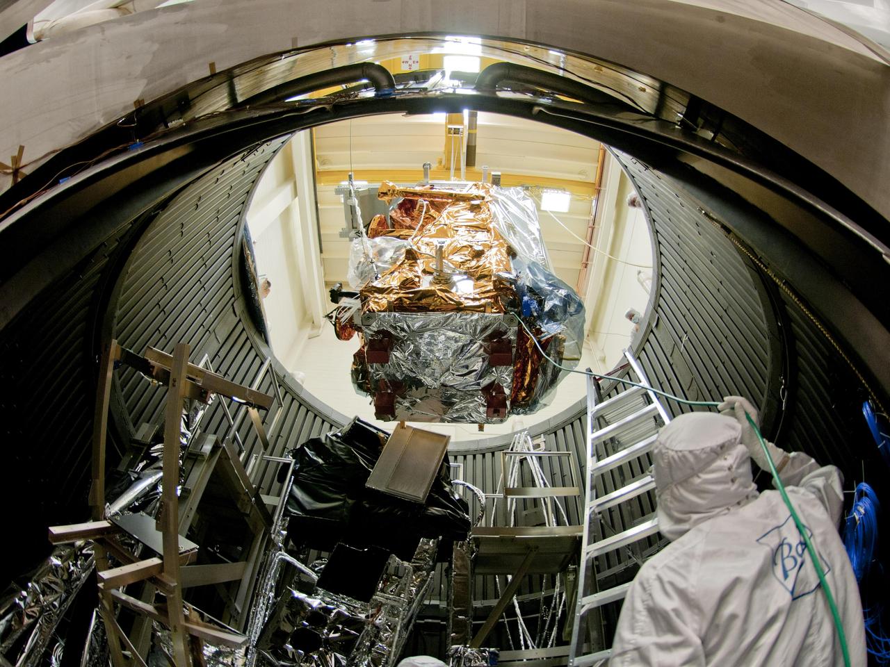
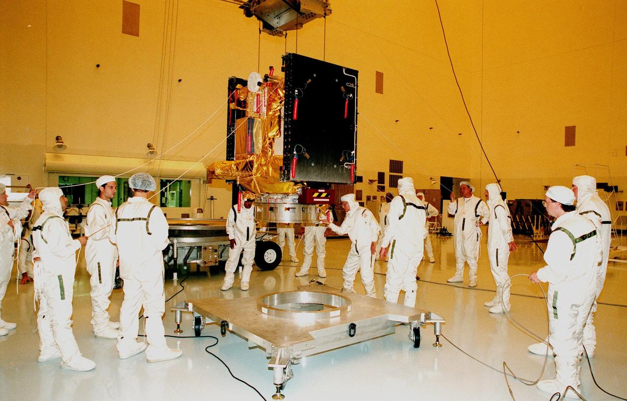
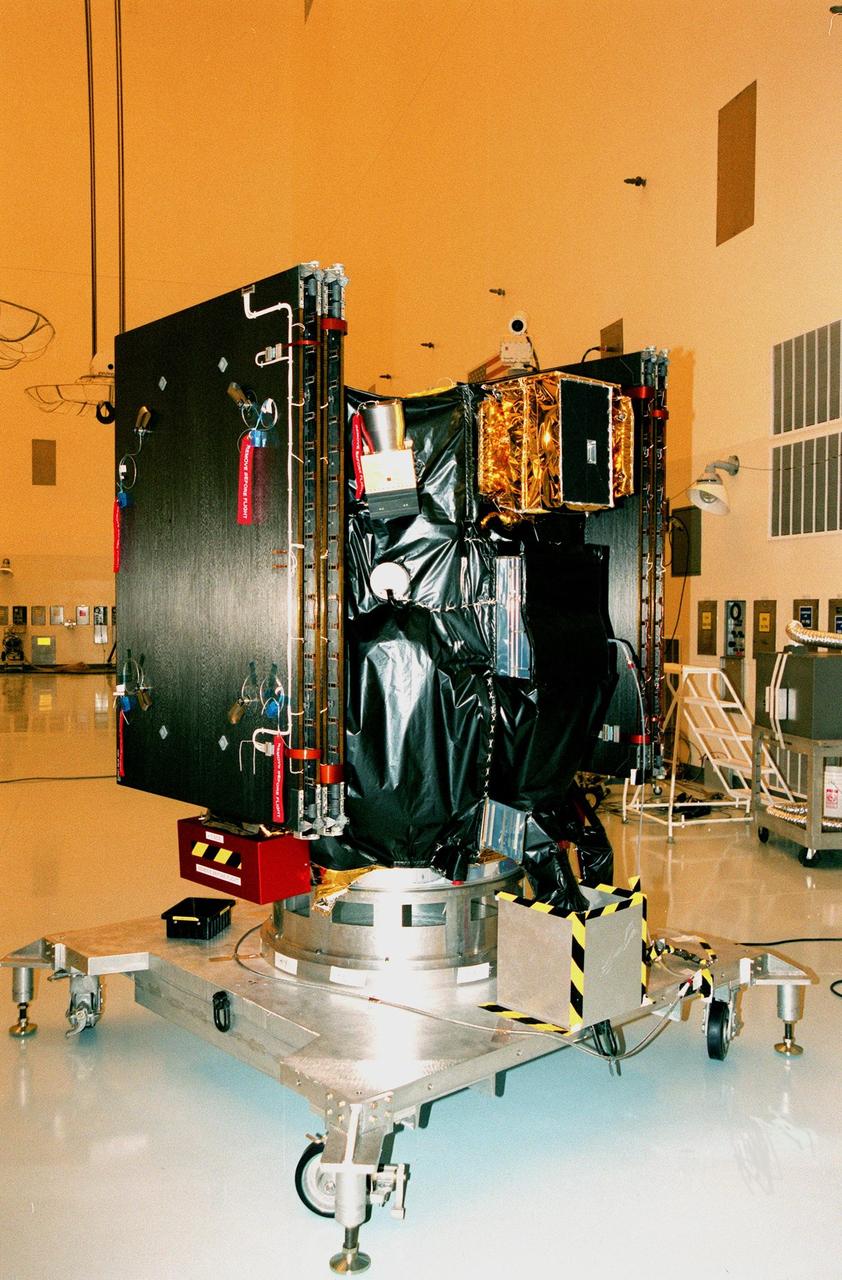
NPP is lowered into the thermal vacuum chamber. Once inside the Iron Maiden (visible in the lower left) is fitted in place. Then air is pumped out of the chamber and temperature extremes are applied to replicate orbit conditions. Credit: Ball Aerospace The NPP satellite sits surrounded by 144 rock concert speakers. They're stacked in a circle 16 feet high in a testing room at Ball Aerospace in Boulder, Colorado. As engineers set up for the environmental test, Pink Floyd's song "Money" plays gently in the background. The music stops. The room clears. Then the sound engineer wearing earplugs and headphones in the control room next door flips a switch. Slowly, the noise of thousands of pounds of exploding rocket fuel builds louder and louder until it blasts the satellite at a deafening 143.6 decibels -- loud enough to cause serious damage and pain to unprotected ears. "I was outside the building when they did the full level acoustics," says Glenn Iona, NPP Chief Engineer at NASA Goddard Space Flight Center, Greenbelt, Md. "and I could feel the ground shaking." To read more go to: <a href="http://www.nasa.gov/mission_pages/NPP/news/npp-testing.html" rel="nofollow">www.nasa.gov/mission_pages/NPP/news/npp-testing.html</a> <b><a href="http://www.nasa.gov/centers/goddard/home/index.html" rel="nofollow">NASA Goddard Space Flight Center</a></b> enables NASA’s mission through four scientific endeavors: Earth Science, Heliophysics, Solar System Exploration, and Astrophysics. Goddard plays a leading role in NASA’s accomplishments by contributing compelling scientific knowledge to advance the Agency’s mission. <b>Follow us on <a href="http://twitter.com/NASA_GoddardPix" rel="nofollow">Twitter</a></b> <b>Like us on <a href="http://www.facebook.com/pages/Greenbelt-MD/NASA-Goddard/395013845897?ref=tsd" rel="nofollow">Facebook</a></b> <b>Find us on <a href="http://web.stagram.com/n/nasagoddard/?vm=grid" rel="nofollow">Instagram</a></b>
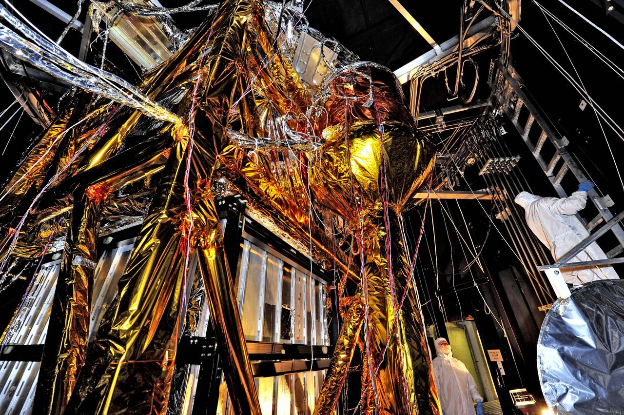
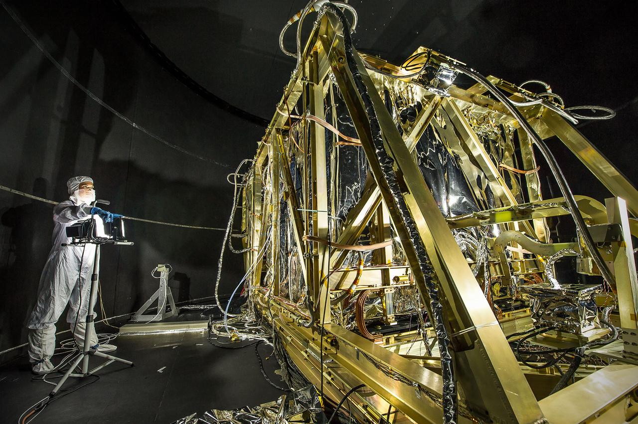
NASA image release August 23, 2012 What looks like a giant golden spider weaving a web of cables and cords, is actually ground support equipment, including the Optical Telescope Simulator (OSIM), for the James Webb Space Telescope. OSIM's job is to generate a beam of light just like the one that the real telescope optics will feed into the actual flight instruments. Because the real flight instruments will be used to test the real flight telescope, their alignment and performance first have to be verified by using the OSIM. Engineers are thoroughly checking out OSIM now in preparation for using it to test the flight science instruments later. This photo was taken from inside a large thermal-vacuum chamber called the Space Environment Simulator (SES), at NASA's Goddard Space Flight Center in Greenbelt, Md. Engineers have blanketed the structure of the OSIM with special insulating material to help control its temperature while it goes into the deep freeze testing that mimics the chill of space that Webb will ultimately experience in its operational orbit over 1 million miles from Earth. The golden-colored thermal blankets are made of aluminized kapton, a polymer film that remains stable over a wide range of temperatures. The structure that looks like a silver and black cube underneath the "spider" is a set of cold panels that surround OSIM's optics. During testing, OSIM's temperature will drop to 100 Kelvin (-280 F or -173 C) as liquid nitrogen flows through tubes welded to the chamber walls and through tubes along the silver panels surrounding OSIM's optics. These cold panels will keep the OSIM optics very cold, but the parts covered by the aluminized kapton blankets will stay warm. "Some blankets have silver facing out and gold facing in, or inverted, or silver on both sides, etc.," says Erin Wilson, a Goddard engineer. "Depending on which side of the blanket your hardware is looking at, the blankets can help it get colder or stay warmer, in an environmental test." Another reason for thermal blankets is to shield the cold OSIM optics from unwanted stray infrared light. When the OSIM is pointing its calibrated light beam at Webb's science instruments, engineers don't want any stray infrared light, such as "warm photons" from warm structures, leaking into the instruments' field of view. Too much of this stray light would raise the background too much for the instruments to "see" light from the OSIM—it would be like trying to photograph a lightning bug flying in front of car headlights. To get OSIM's optics cold, the inside of the chamber has to get cold, and to do that, all the air has to be pumped out to create a vacuum. Then liquid nitrogen has to be run though the plumbing along the inner walls of the chamber. Wilson notes that's why the blankets have to have vents in them: "That way, the air between all the layers can be evacuated as the chamber pressure drops, otherwise the blankets could pop," says Wilson. The most powerful space telescope ever built, Webb is the successor to NASA's Hubble Space Telescope. Webb's four instruments will reveal how the universe evolved from the Big Bang to the formation of our solar system. Webb is a joint project of NASA, the European Space Agency and the Canadian Space Agency. Credit: NASA/GSFC/Chris Gunn <b><a href="http://www.nasa.gov/audience/formedia/features/MP_Photo_Guidelines.html" rel="nofollow">NASA image use policy.</a></b> <b><a href="http://www.nasa.gov/centers/goddard/home/index.html" rel="nofollow">NASA Goddard Space Flight Center</a></b> enables NASA’s mission through four scientific endeavors: Earth Science, Heliophysics, Solar System Exploration, and Astrophysics. Goddard plays a leading role in NASA’s accomplishments by contributing compelling scientific knowledge to advance the Agency’s mission. <b>Follow us on <a href="http://twitter.com/NASA_GoddardPix" rel="nofollow">Twitter</a></b> <b>Like us on <a href="http://www.facebook.com/pages/Greenbelt-MD/NASA-Goddard/395013845897?ref=tsd" rel="nofollow">Facebook</a></b> <b>Find us on <a href="http://instagrid.me/nasagoddard/?vm=grid" rel="nofollow">Instagram</a></b>
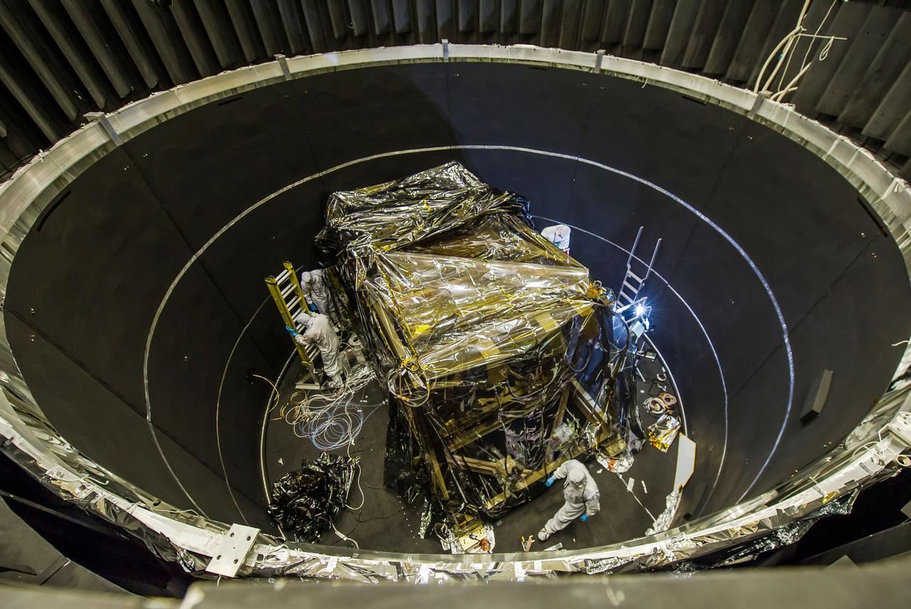
This photo was captured from outside the enormous mouth of NASA's giant thermal vacuum chamber, called Chamber A, at Johnson Space Center in Houston. Previously used for manned spaceflight missions, this historic chamber is now filled with engineers and technicians preparing a lift system that will be used to hold the James Webb Space Telescope during testing. The James Webb Space Telescope is the scientific successor to NASA's Hubble Space Telescope. It will be the most powerful space telescope ever built. Webb is an international project led by NASA with its partners, the European Space Agency and the Canadian Space Agency. Credit: NASA/Goddard/Chris Gunn <b><a href="http://www.nasa.gov/audience/formedia/features/MP_Photo_Guidelines.html" rel="nofollow">NASA image use policy.</a></b> <b><a href="http://www.nasa.gov/centers/goddard/home/index.html" rel="nofollow">NASA Goddard Space Flight Center</a></b> enables NASA’s mission through four scientific endeavors: Earth Science, Heliophysics, Solar System Exploration, and Astrophysics. Goddard plays a leading role in NASA’s accomplishments by contributing compelling scientific knowledge to advance the Agency’s mission. <b>Follow us on <a href="http://twitter.com/NASAGoddardPix" rel="nofollow">Twitter</a></b> <b>Like us on <a href="http://www.facebook.com/pages/Greenbelt-MD/NASA-Goddard/395013845897?ref=tsd" rel="nofollow">Facebook</a></b> <b>Find us on <a href="http://instagrid.me/nasagoddard/?vm=grid" rel="nofollow">Instagram</a></b>

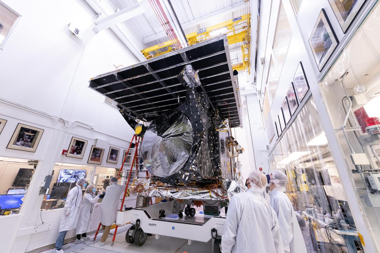
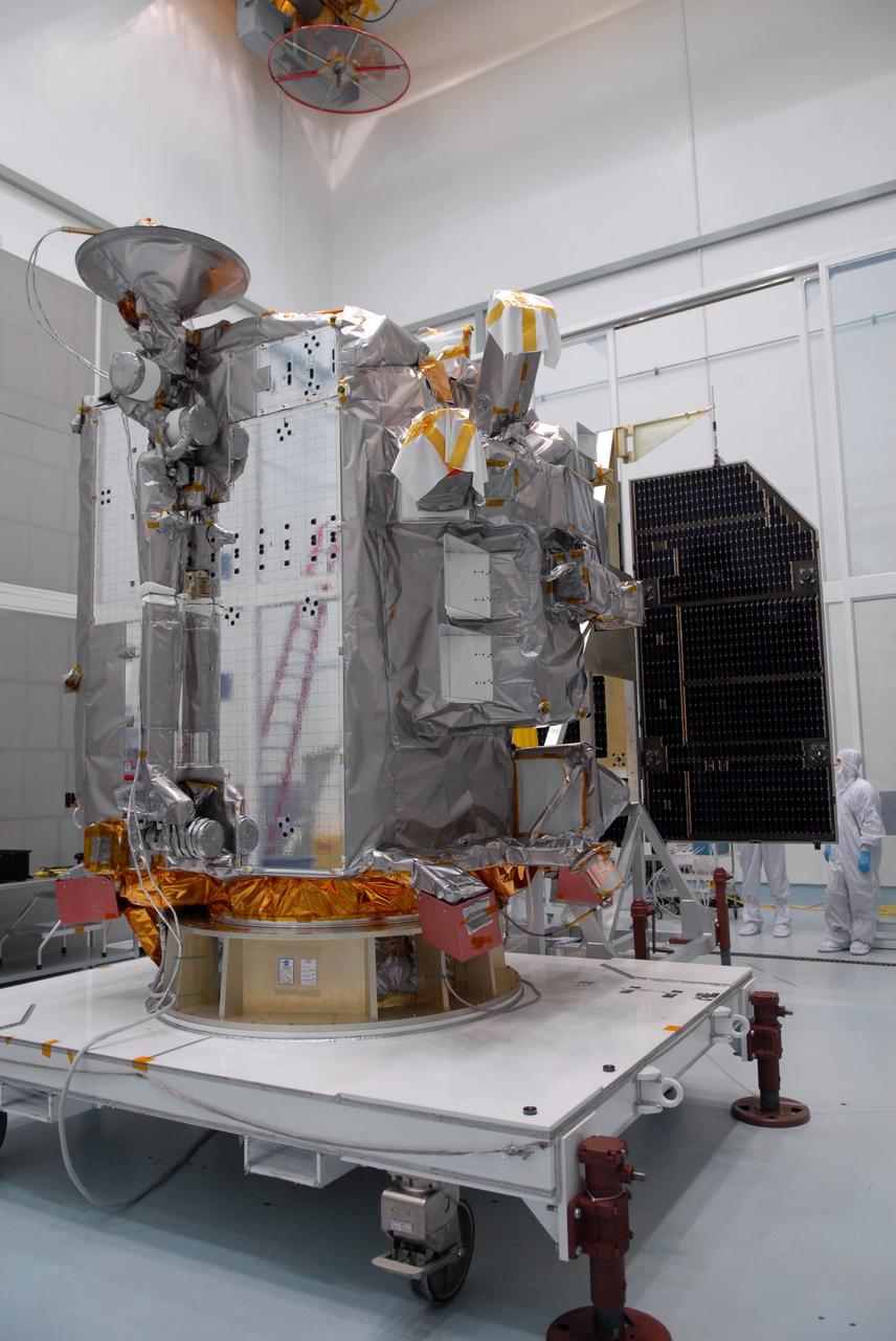
A major component of NASA's Psyche spacecraft has been delivered to NASA's Jet Propulsion Laboratory in Southern California, where the phase known as assembly, test, and launch operations (ATLO) is now underway. This photo, shot March 28, 2021 shows engineers and technicians preparing to move the Solar Electric Propulsion (SEP) Chassis from its shipping container to a dolly in High Bay 1 of JPL's Spacecraft Assembly Facility. The photo was captured just after the chassis was delivered to JPL by Maxar Technologies. Maxar's team in Palo Alto, California, designed and built the SEP Chassis, which includes all the primary and secondary structure and the hardware components needed for the high-power electrical system, the propulsion system, the thermal system, guidance and navigation sensors and actuators, and the high-gain antenna. Over the next year, additional hardware will be added to the spacecraft including the command and data handling system, a power distribution assembly, the X-band telecommunications hardware suite, three science instruments (two imagers, two magnetometers, and a gamma ray neutron Spectrometer), and a deep space optical communications technology demonstrator. The spacecraft will finish assembly and then undergo rigorous checkout and testing before being shipped to NASA's Kennedy Space Center in Cape Canaveral, Florida, for an August 2022 launch to the main asteroid belt. Psyche will arrive at the metal-rich asteroid of the same name in 2026, orbiting for 21 months to investigate its composition. Scientists think that Psyche is made up of mostly iron and nickel — similar to Earth's core. Exploring the asteroid could give valuable insight into how our own planet and others formed. https://photojournal.jpl.nasa.gov/catalog/PIA24475
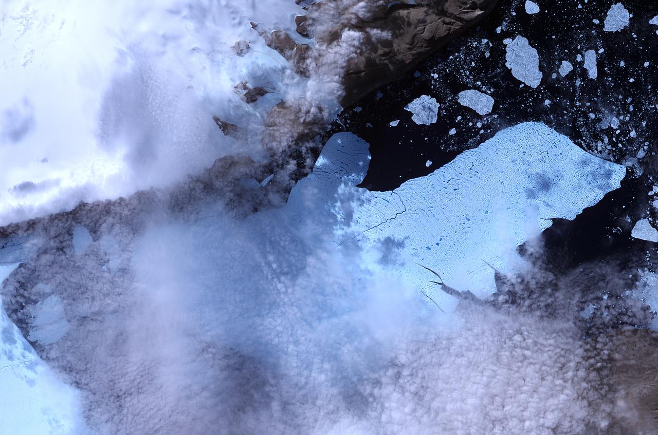
NASA image acquired August 11, 2010. After breaking off the Petermann Glacier on August 5, 2010, a massive ice island floated slowly down the fjord toward the Nares Strait. The Advanced Spaceborne Thermal Emission and Reflection Radiometer (ASTER) on NASA’s Terra satellite captured this false-color image of the ice island on August 11, 2010. In this image, ice is light blue, water is nearly black, and clouds are nearly white. Although a bank of thin clouds hovers over the fjord, the southernmost margin of the ice island is still visible. Toward the north, the leading edge of the ice island retains the same shape it had days earlier, at the time of the initial calving. NASA Earth Observatory image created by Jesse Allen, using data provided courtesy of NASA/GSFC/METI/ERSDAC/JAROS, and U.S./Japan ASTER Science Team. Caption by Michon Scott. Instrument: Terra - ASTER To see more images from of the glacier go to: <a href="http://earthobservatory.nasa.gov/NaturalHazards/event.php?id=45116" rel="nofollow">earthobservatory.nasa.gov/NaturalHazards/event.php?id=45116</a> <b><a href="http://www.nasa.gov/centers/goddard/home/index.html" rel="nofollow">NASA Goddard Space Flight Center</a></b> is home to the nation's largest organization of combined scientists, engineers and technologists that build spacecraft, instruments and new technology to study the Earth, the sun, our solar system, and the universe. <b>Follow us on <a href="http://twitter.com/NASA_GoddardPix" rel="nofollow">Twitter</a></b> <b>Join us on <a href="http://www.facebook.com/pages/Greenbelt-MD/NASA-Goddard/395013845897?ref=tsd" rel="nofollow">Facebook</a><b></b></b>
Engineers guiding the GPM Core Observatory into the thermal vacuum chamber. Credit: NASA/Goddard The Global Precipitation Measurement (GPM) mission is an international partnership co-led by NASA and the Japan Aerospace Exploration Agency (JAXA) that will provide next-generation global observations of precipitation from space. GPM will study global rain, snow and ice to better understand our climate, weather, and hydrometeorological processes. As of Novermber 2013 the GPM Core Observatory is in the final stages of testing at NASA Goddard Space Flight Center. The satellite will be flown to Japan in the fall of 2013 and launched into orbit on an HII-A rocket in early 2014. For more on the GPM mission, visit <a href="http://gpm.gsfc.nasa.gov/" rel="nofollow">gpm.gsfc.nasa.gov/</a>. <b><a href="http://www.nasa.gov/audience/formedia/features/MP_Photo_Guidelines.html" rel="nofollow">NASA image use policy.</a></b> <b><a href="http://www.nasa.gov/centers/goddard/home/index.html" rel="nofollow">NASA Goddard Space Flight Center</a></b> enables NASA’s mission through four scientific endeavors: Earth Science, Heliophysics, Solar System Exploration, and Astrophysics. Goddard plays a leading role in NASA’s accomplishments by contributing compelling scientific knowledge to advance the Agency’s mission. <b>Follow us on <a href="http://twitter.com/NASA_GoddardPix" rel="nofollow">Twitter</a></b> <b>Like us on <a href="http://www.facebook.com/pages/Greenbelt-MD/NASA-Goddard/395013845897?ref=tsd" rel="nofollow">Facebook</a></b> <b>Find us on <a href="http://instagram.com/nasagoddard?vm=grid" rel="nofollow">Instagram</a></b>
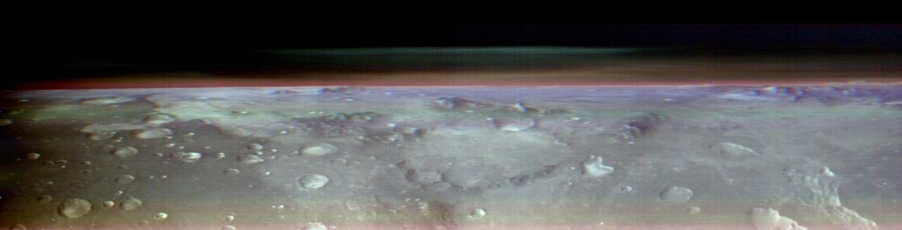
This view of Mars was captured by NASA's Odyssey orbiter using its Thermal Emission Imaging System, or THEMIS, camera. This image is a false color composite, made by combining three channels of infrared data that highlight water-ice clouds and dust in the atmosphere. This panorama was one of 10 captured on May 9, 2023, from an altitude of roughly 250 miles (400 kilometers) above the Martian surface – about the same altitude at which the International Space Station flies over Earth. The 10 panoramas of the Martian horizon were taken to capture a one-of-a-kind view of the Martian atmosphere as Odyssey circled the planet during its two-hour orbit. The reason why the view is so uncommon is because of the challenges involved in creating it. Engineers at NASA's Jet Propulsion Laboratory in Southern California (which leads the Odyssey mission) and Lockheed Martin Space (which built Odyssey and co-leads day-to-day operations) spent three months planning the observations. THEMIS' sensitivity to warmth enables it to map ice, rock, sand, and dust, along with temperature changes, on the planet's surface. It can also measure how much water ice or dust is in the atmosphere, but only in a narrow column directly below the spacecraft. That's because THEMIS is fixed in place on the orbiter; it usually points straight down. Mission scientists wanted a more expansive view of the atmosphere. Seeing where those layers of water-ice clouds and dust are in relation to each other – whether there's one layer or several stacked on top of each other – helps them improve models of Mars' atmosphere. Because THEMIS can't pivot, adjusting the angle of the camera requires adjusting the position of the whole spacecraft. In this case, the team needed to rotate the orbiter almost 90 degrees while making sure the Sun would still shine on the spacecraft's solar panels but not on sensitive equipment that could overheat. The easiest orientation turned out to be one where the orbiter's antenna pointed away from Earth. That meant the team was out of communication with Odyssey for several hours until the operation was completed. https://photojournal.jpl.nasa.gov/catalog/PIA26203

Engineer Erin Wilson adds aluminum tape to electrical cables to protect them from the cold during environmental testing of special optical equipment. These tests will verify the alignment of the actual flight instruments that will fly aboard NASA’s James Webb Space Telescope. "Because the flight science instruments detect infrared light, they must be extremely cold to work, and so the environment we test them in must be extremely cold too," Wilson says. Wilson is working in the Space Environment Simulator thermal-vacuum chamber at NASA's Goddard Space Flight Center in Greenbelt, Md. The subject of the testing is the Optical Telescope Element (OTE) Simulator, or OSIM. The hardware seen in the background is the Beam Image Analyzer, which will be used to measure OSIM. It sits above the OSIM, which is under the platform that Wilson is working on. The OSIM is about two stories tall and almost as wide as the whole test chamber. The job of the OSIM is to generate a beam of light just like the one that the real telescope optics will feed into the actual flight science instruments. Because the real flight science instruments will be used to test the real flight telescope, their alignment and performance have to be verified first, using OSIM, and before that can happen, the OSIM has to tested and verified. In space, the telescope optics act as Webb’s eye, and on the ground, the OSIM substitutes for the telescope optics, says Robert Rashford, manager for the OSIM as well as the Integrated Science Instrument Module (ISIM) Electronics Compartment. This hardware is being tested in an environment that mimics the hard vacuum and cold temperatures that Webb will experience in space. After Erin and others were done setting things up in the test chamber, Goddard engineers sealed it up, evacuated all the air and lowered the temperature of the equipment being tested to 42 Kelvin (-384-point-1 Fahrenheit or -231-point-1 Celsius). "It has taken a little over a month to get temperatures cold enough to duplicate the temperatures that Webb will see in operation in space," Rashford says. In the next couple weeks Rashford and the team of Goddard engineers will measure the OSIM with the Beam Image Analyzer. This extremely cold or “cryogenic” optical testing and verification process will likely take 90 days to complete. Laura Betz NASA's Goddard Space Flight Center, Greenbelt, Md. <b><a href="http://www.nasa.gov/audience/formedia/features/MP_Photo_Guidelines.html" rel="nofollow">NASA image use policy.</a></b> <b><a href="http://www.nasa.gov/centers/goddard/home/index.html" rel="nofollow">NASA Goddard Space Flight Center</a></b> enables NASA’s mission through four scientific endeavors: Earth Science, Heliophysics, Solar System Exploration, and Astrophysics. Goddard plays a leading role in NASA’s accomplishments by contributing compelling scientific knowledge to advance the Agency’s mission. <b>Follow us on <a href="http://twitter.com/NASA_GoddardPix" rel="nofollow">Twitter</a></b> <b>Like us on <a href="http://www.facebook.com/pages/Greenbelt-MD/NASA-Goddard/395013845897?ref=tsd" rel="nofollow">Facebook</a></b> <b>Find us on <a href="http://instagrid.me/nasagoddard/?vm=grid" rel="nofollow">Instagram</a></b>
Inside NASA's giant thermal vacuum chamber, called Chamber A, at NASA's Johnson Space Center in Houston, the James Webb Space Telescope's Pathfinder backplane test model, is being prepared for its cryogenic test. Previously used for manned spaceflight missions, this historic chamber is now filled with engineers and technicians preparing for a crucial test. Exelis developed and installed the optical test equipment in the chamber. "The optical test equipment was developed and installed in the chamber by Exelis," said Thomas Scorse, Exelis JWST Program Manager. "The Pathfinder telescope gives us our first opportunity for an end-to-end checkout of our equipment." "This will be the first time on the program that we will be aligning two primary mirror segments together," said Lee Feinberg, NASA Optical Telescope Element Manager. "In the past, we have always tested one mirror at a time but this time we will use a single test system and align both mirrors to it as though they are a single monolithic mirror." The James Webb Space Telescope is the scientific successor to NASA's Hubble Space Telescope. It will be the most powerful space telescope ever built. Webb is an international project led by NASA with its partners, the European Space Agency and the Canadian Space Agency. Image credit: NASA/Chris Gunn Text credit: Laura Betz, NASA's Goddard Space Flight Center, Greenbelt, Maryland <b><a href="http://www.nasa.gov/audience/formedia/features/MP_Photo_Guidelines.html" rel="nofollow">NASA image use policy.</a></b> <b><a href="http://www.nasa.gov/centers/goddard/home/index.html" rel="nofollow">NASA Goddard Space Flight Center</a></b> enables NASA’s mission through four scientific endeavors: Earth Science, Heliophysics, Solar System Exploration, and Astrophysics. Goddard plays a leading role in NASA’s accomplishments by contributing compelling scientific knowledge to advance the Agency’s mission. <b>Follow us on <a href="http://twitter.com/NASAGoddardPix" rel="nofollow">Twitter</a></b> <b>Like us on <a href="http://www.facebook.com/pages/Greenbelt-MD/NASA-Goddard/395013845897?ref=tsd" rel="nofollow">Facebook</a></b> <b>Find us on <a href="http://instagrid.me/nasagoddard/?vm=grid" rel="nofollow">Instagram</a></b>
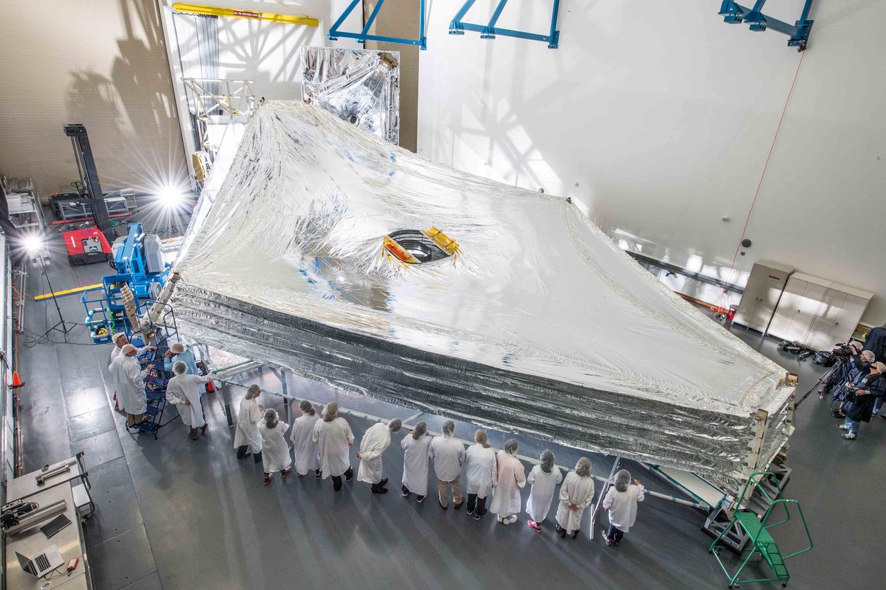
The Sunshield on NASA's James Webb Space Telescope is the largest part of the observatory—five layers of thin membrane that must unfurl reliably in space to precise tolerances. Last week, for the first time, engineers stacked and unfurled a full-sized test unit of the Sunshield and it worked perfectly. The Sunshield is about the length of a tennis court, and will be folded up like an umbrella around the Webb telescope’s mirrors and instruments during launch. Once it reaches its orbit, the Webb telescope will receive a command from Earth to unfold, and separate the Sunshield's five layers into their precisely stacked arrangement with its kite-like shape. The Sunshield test unit was stacked and expanded at a cleanroom in the Northrop Grumman facility in Redondo Beach, California. The Sunshield separates the observatory into a warm sun-facing side and a cold side where the sunshine is blocked from interfering with the sensitive infrared instruments. The infrared instruments need to be kept very cold (under 50 K or -370 degrees F) to operate. The Sunshield protects these sensitive instruments with an effective sun protection factor or SPF of 1,000,000 (suntan lotion generally has an SPF of 8-50). In addition to providing a cold environment, the Sunshield provides a thermally stable environment. This stability is essential to maintaining proper alignment of the primary mirror segments as the telescope changes its orientation to the sun. The James Webb Space Telescope is the successor to NASA's Hubble Space Telescope. It will be the most powerful space telescope ever built. Webb is an international project led by NASA with its partners, the European Space Agency and the Canadian Space Agency. For more information about the Webb telescope, visit: <a href="http://www.jwst.nasa.gov" rel="nofollow">www.jwst.nasa.gov</a> or <a href="http://www.nasa.gov/webb" rel="nofollow">www.nasa.gov/webb</a> For more information on the Webb Sunshield, visit: <a href="http://jwst.nasa.gov/sunshield.html" rel="nofollow">jwst.nasa.gov/sunshield.html</a> Credit: NASA/Goddard/Chris Gunn <b><a href="http://www.nasa.gov/audience/formedia/features/MP_Photo_Guidelines.html" rel="nofollow">NASA image use policy.</a></b> <b><a href="http://www.nasa.gov/centers/goddard/home/index.html" rel="nofollow">NASA Goddard Space Flight Center</a></b> enables NASA’s mission through four scientific endeavors: Earth Science, Heliophysics, Solar System Exploration, and Astrophysics. Goddard plays a leading role in NASA’s accomplishments by contributing compelling scientific knowledge to advance the Agency’s mission. <b>Follow us on <a href="http://twitter.com/NASAGoddardPix" rel="nofollow">Twitter</a></b> <b>Like us on <a href="http://www.facebook.com/pages/Greenbelt-MD/NASA-Goddard/395013845897?ref=tsd" rel="nofollow">Facebook</a></b> <b>Find us on <a href="http://instagram.com/nasagoddard?vm=grid" rel="nofollow">Instagram</a></b>
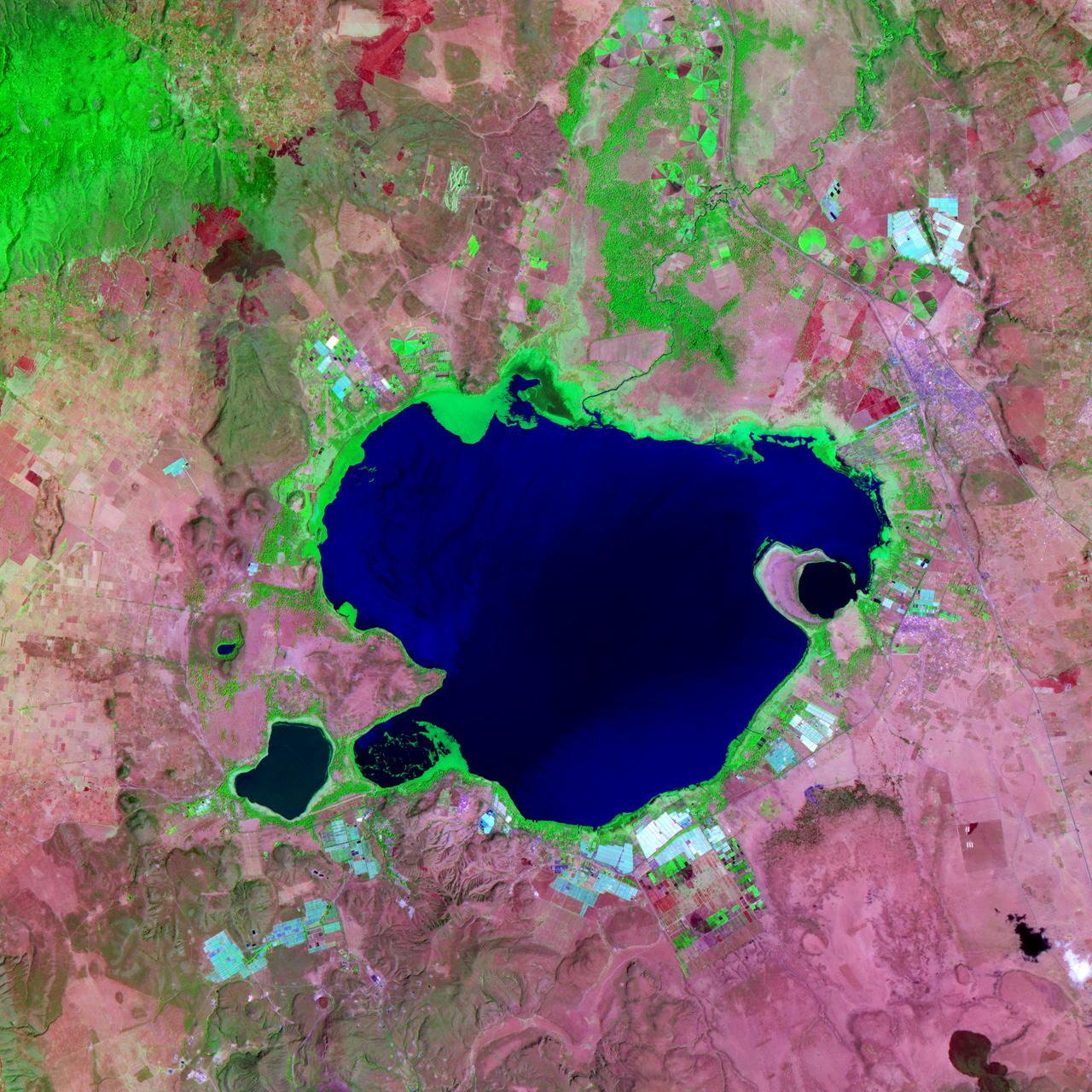
NASA satellite image acquired February 2, 2008. Outside the ground is frozen, quite possibly covered in snow and ice, and yet, stroll through a supermarket in North America or Europe in February, and you’ll be confronted with large displays of roses. We expect flowers in winter, and equatorial countries meet those expectations. A quarter of the cut flowers sold in Europe are grown in Kenya. Straddling the equator, Kenya gets steady sunlight dealt out in days that vary little in length. It’s the perfect climate for flowers year-round. The center of Kenya’s flower industry is Lake Naivasha, shown here. The Advanced Spaceborne Thermal Emission and Reflection Radiometer (ASTER) flying on NASA’s Terra satellite captured this image of Lake Naivasha on February 2, 2008. Bright white squares mix with fields of green, tan, and purple along the shores of the lake. Sunlight glints off the long rows of glass greenhouses, turning them silvery blue and white in this view from space. Fallow fields are tan and pink, while growing plants turn the ground bright green. Roses, lilies, and carnations are the most common flowers grown in the greenhouses and fields scattered around the lake. The large-scale industry shown here extends into small-scale rural farms elsewhere in Kenya, where smaller filler flowers are grown. The flowers provide an important source of income to Kenya, but the industry comes with a price. Flowers are not held to the same standards for chemical residues as food products, which are tightly regulated. Strong chemical pesticides can be used on the flowers to produce the perfect, pest-free bloom, and this could pose a health risk to workers and local wildlife, including hippos, environmental groups told the Food and Agriculture Organization of the United Nations in 2002. The chemicals may also have threatened the water quality of Lake Naivasha, one of Kenya’s few freshwater lakes. The Kenya Flower Council instituted a code of conduct establishing guidelines for pesticide that phases out the use of one of the most toxic pesticides. NASA image created by Jesse Allen, using data provided courtesy of NASA/GSFC/METI/ERSDAC/JAROS, and U.S./Japan ASTER Science Team. Caption by Holli Riebeek. Instrument: Terra - ASTER <b><a href="http://www.nasa.gov/centers/goddard/home/index.html" rel="nofollow">NASA Goddard Space Flight Center</a></b> is home to the nation's largest organization of combined scientists, engineers and technologists that build spacecraft, instruments and new technology to study the Earth, the sun, our solar system, and the universe.
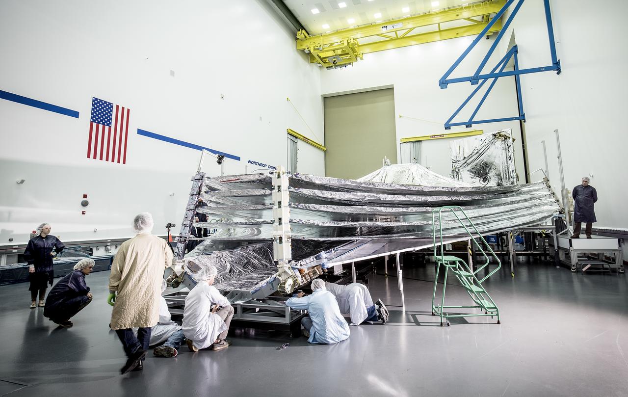
The sunshield on NASA's James Webb Space Telescope is the largest part of the observatory—five layers of thin, silvery membrane that must unfurl reliably in space. The precision in which the tennis-court sized sunshield has to open must be no more than a few centimeters different from its planned position. In this photo, engineers and scientists examine the sunshield layers on this full-sized test unit. Because there's a layer of the shiny silver material on the base under the five layers of the sunshield, it appears as if the sunshield has a mouth that is "open wide" while engineers take a look. The photo was taken in a clean room at Northrop Grumman Corporation, Redondo Beach, California. The sunshield separates the observatory into a warm sun-facing side and a cold side where the sunshine is blocked from interfering with the sensitive infrared instruments. The infrared instruments need to be kept very cold (under 50 K or -370 degrees Fahrenheit) to operate. The sunshield protects these sensitive instruments with an effective sun protection factor, or SPF, of 1,000,000. Sunscreen generally has an SPF of 8 to 50. In addition to providing a cold environment, the sunshield provides a thermally stable environment. This stability is essential to maintaining proper alignment of the primary mirror segments as the telescope changes its orientation to the sun. Earlier this year, the first flight layer of the sunshield was delivered to Northrop Grumman. Northrop Grumman is designing the Webb Telescope’s sunshield for NASA’s Goddard Space Flight Center, in Greenbelt, Maryland. Innovative sunshield membranes are being designed and manufactured by NeXolve Corporation of Huntsville, Alabama. The James Webb Space Telescope is the successor to NASA's Hubble Space Telescope. It will be the most powerful space telescope ever built. Webb is an international project led by NASA with its partners, the European Space Agency and the Canadian Space Agency. For more information about the Webb telescope, visit: <a href="http://www.jwst.nasa.gov" rel="nofollow">www.jwst.nasa.gov</a> or <a href="http://www.nasa.gov/webb" rel="nofollow">www.nasa.gov/webb</a> For more information on the Webb Sunshield, visit: <a href="http://jwst.nasa.gov/sunshield.html" rel="nofollow">jwst.nasa.gov/sunshield.html</a> Photo credit: Alex Evers/Northrop Grumman Corporation <b><a href="http://www.nasa.gov/audience/formedia/features/MP_Photo_Guidelines.html" rel="nofollow">NASA image use policy.</a></b> <b><a href="http://www.nasa.gov/centers/goddard/home/index.html" rel="nofollow">NASA Goddard Space Flight Center</a></b> enables NASA’s mission through four scientific endeavors: Earth Science, Heliophysics, Solar System Exploration, and Astrophysics. Goddard plays a leading role in NASA’s accomplishments by contributing compelling scientific knowledge to advance the Agency’s mission. <b>Follow us on <a href="http://twitter.com/NASAGoddardPix" rel="nofollow">Twitter</a></b> <b>Like us on <a href="http://www.facebook.com/pages/Greenbelt-MD/NASA-Goddard/395013845897?ref=tsd" rel="nofollow">Facebook</a></b> <b>Find us on <a href="http://instagrid.me/nasagoddard/?vm=grid" rel="nofollow">Instagram</a></b>

NASA image acquired August 4, 2010 Though many areas in northwest Pakistan were bracing for heavy rain and additional flash flooding on August 4, 2010, the city of Kheshgi, in northwest Pakistan, had clear skies. This image, taken by the Advanced Spaceborne Thermal Emission and Reflection Radiometer (ASTER) on NASA’s Terra satellite reveals a city awash in flood water. Thick with mud, the Kabul River is pale green in this false color image. Clearer water is dark blue. The river flows through its usual channel, but in places, water seeps over the channel and across the landscape. The buildings and roads of Kheshgi are silver. Spots of turquoise blue—shallow, muddy water or water-logged ground—covers several sections of the city. On the south side of the Kabul River, water flows down the hills, washing over neighborhoods. The bare ground in the hills is brown and tan. Plant-covered land, red in this image, is divided into long, narrow rectangles, pointing to agriculture. Geometric shapes under the water near the river are probably submerged fields of crops. Thousands of acres of crops had been lost in floods throughout Pakistan, said the United Nations. Kheshgi is in the Nowshera district in the Khyber Pakhutnkhwa province. As of August 2, Khyber Pakhutnkhwa was the hardest hit province in Pakistan, said the United Nations, and Nowshera was the most impacted district in the province. Nowshera reported 500,000 people displaced with 161 dead, said the Government of Khuber Pakhtunkhwa. The floods affected communities throughout Pakistan. More than 1,100 people had died, 15,000 homes were damaged or destroyed, and at least one million people were in need of emergency assistance throughout Pakistan, said the United Nations on August 2. The floods occurred as unusually heavy monsoon rains fell over Pakistan. NASA image courtesy NASA/GSFC/MITI/ERSDAC/JAROS, and U.S./Japan ASTER Science Team. Caption by Holli Riebeek. Instrument: Terra - ASTER Credit: <b><a href="#//earthobservatory.nasa.gov/" rel="nofollow"> NASA’s Earth Observatory</a></b> To learn more about this image go here: <a href="http://earthobservatory.nasa.gov/NaturalHazards/view.php?id=45050" rel="nofollow">earthobservatory.nasa.gov/NaturalHazards/view.php?id=45050</a> Or here: <a href="http://earthobservatory.nasa.gov/NaturalHazards/view.php?id=45343" rel="nofollow">earthobservatory.nasa.gov/NaturalHazards/view.php?id=45343</a> <b><a href="http://www.nasa.gov/centers/goddard/home/index.html" rel="nofollow">NASA Goddard Space Flight Center</a></b> is home to the nation's largest organization of combined scientists, engineers and technologists that build spacecraft, instruments and new technology to study the Earth, the sun, our solar system, and the universe. <b>Follow us on <a href="http://twitter.com/NASA_GoddardPix" rel="nofollow">Twitter</a></b> <b>Join us on <a href="http://www.facebook.com/pages/Greenbelt-MD/NASA-Goddard/395013845897?ref=tsd" rel="nofollow">Facebook</a></b>
NASA acquired November 24, 2011 From its vantage 824 kilometers (512 miles) above Earth, the Visible Infrared Imager Radiometer Suite (VIIRS) on the NPOESS Preparatory Project (NPP) satellite gets a complete view of our planet every day. This image from November 24, 2011, is the first complete global image from VIIRS. The NPP satellite launched on October 28, 2011, and VIIRS acquired its first measurements on November 21. To date, the images are preliminary, used to gauge the health of the sensor as engineers continue to power it up for full operation. Rising from the south and setting in the north on the daylight side of Earth, VIIRS images the surface in long wedges measuring 3,000 kilometers (1,900 miles) across. The swaths from each successive orbit overlap one another, so that at the end of the day, the sensor has a complete view of the globe. The Arctic is missing because it is too dark to view in visible light during the winter. The NPP satellite was placed in a Sun-synchronous orbit, a unique path that takes the satellite over the equator at the same local (ground) time in every orbit. So, when NPP flies over Kenya, it is about 1:30 p.m. on the ground. When NPP reaches Gabon—about 3,000 kilometers to the west—on the next orbit, it is close to 1:30 p.m. on the ground. This orbit allows the satellite to maintain the same angle between the Earth and the Sun so that all images have similar lighting. The consistent lighting is evident in the daily global image. Stripes of sunlight (sunglint) reflect off the ocean in the same place on the left side of every swath. The consistent angle is important because it allows scientists to compare images from year to year without worrying about extreme changes in shadows and lighting. The image also shows a band of haze along the right side of every orbit swath. When light travels through the atmosphere, it bounces off particles or scatters, making the atmosphere look hazy. The scattering effect is most pronounced along the edge of the swath, where the sensor is looking at an angle through more of the atmosphere. Scientists can correct for this scattering effect, but need measurements from a range of wavelengths to do so. The degree to which light scatters depends partly on the wavelength of the light. Blue light scatters more than red light, for example, which is why the sky is blue. VIIRS measures 22 different wavelengths of light, but not all of the sensor’s detectors are operating at peak performance yet. Those measuring thermal infrared light are not yet cold enough to collect reliable measurements. Once VIIRS begins full operations, it will produce a range of measurements from ocean temperature to clouds to the locations of fires. These measurements will help extend the record from earlier sensors like the Moderate Resolution Imaging Spectroradiometer (MODIS). VIIRS is very similar to MODIS, but flies at a higher altitude to measure the whole planet without gaps. (MODIS daily measurements have gaps at the equator. See the MODIS image from November 24.) VIIRS also sees the Earth in less detail, 375 meters per pixel, compared to 250 meters per pixel for MODIS. Image by NASA’s NPP Land Product Evaluation and Testing Element. Caption by Holli Riebeek. Credit: <b><a href="http://www.earthobservatory.nasa.gov/" rel="nofollow"> NASA Earth Observatory</a></b> <b><a href="http://www.nasa.gov/audience/formedia/features/MP_Photo_Guidelines.html" rel="nofollow">NASA image use policy.</a></b> <b><a href="http://www.nasa.gov/centers/goddard/home/index.html" rel="nofollow">NASA Goddard Space Flight Center</a></b> enables NASA’s mission through four scientific endeavors: Earth Science, Heliophysics, Solar System Exploration, and Astrophysics. Goddard plays a leading role in NASA’s accomplishments by contributing compelling scientific knowledge to advance the Agency’s mission. <b>Follow us on <a href="http://twitter.com/NASA_GoddardPix" rel="nofollow">Twitter</a></b> <b>Like us on <a href="http://www.facebook.com/pages/Greenbelt-MD/NASA-Goddard/395013845897?ref=tsd" rel="nofollow">Facebook</a></b> <b>Find us on <a href="http://instagrid.me/nasagoddard/?vm=grid" rel="nofollow">Instagram</a></b>