Set up of a Brayton Cycle Power System test in the Space Power Facility’s massive vacuum chamber at the National Aeronautics and Space Administration’s (NASA) Plum Brook Station in Sandusky, Ohio. The $28.4-million facility, which began operations in 1969, is the largest high vacuum chamber ever built. The chamber is 100 feet in diameter and 120 feet high. It can produce a vacuum deep enough to simulate the conditions at 300 miles altitude.  The Space Power Facility was originally designed to test nuclear-power sources for spacecraft, but it was never used for that purpose.   The Space Power Facility was first used to test a 15 to 20-kilowatt Brayton Cycle Power System for space applications. Three different methods of simulating solar heat were employed during the tests.    Lewis researchers studied the Brayton power system extensively in the 1960s and 1970s. The Brayton engine converted solar thermal energy into electrical power. The system operated on a closed-loop Brayton thermodynamic cycle with a helium-xenon gas mixture as its working fluid. A space radiator was designed to serve as the system’s waste heat rejecter. The radiator was later installed in the vacuum chamber and tested in a simulated space environment to determine its effect on the power conversion system. The Brayton system was subjected to simulated orbits with 62 minutes of sun and 34 minutes of shade.
Brayton Cycle Power System in the Space Power Facility
The Orion Crew Module Adapter simulator arrives at NASA Glenn's Plum Brook Station Space Power Facility in Sandusky, Ohio on June 24, 2015. Part of Batch image transfer from Flickr.
Space Power Facility
The Orion Crew Module Adapter simulator arrives at NASA Glenn's Plum Brook Station Space Power Facility in Sandusky, Ohio on June 24, 2015. Part of Batch image transfer from Flickr.
Space Power Facility
The Orion Crew Module Adapter simulator arrives at NASA Glenn's Plum Brook Station Space Power Facility in Sandusky, Ohio on June 24, 2015. Part of Batch image transfer from Flickr.
Space Power Facility
The Orion Crew Module Adapter simulator arrives at NASA Glenn's Plum Brook Station Space Power Facility in Sandusky, Ohio on June 24, 2015. Part of Batch image transfer from Flickr.
Space Power Facility
The Orion Crew Module Adapter simulator arrives at NASA Glenn's Plum Brook Station Space Power Facility in Sandusky, Ohio on June 24, 2015. Part of Batch image transfer from Flickr.
Space Power Facility
The Orion Crew Module Adapter simulator arrives at NASA Glenn's Plum Brook Station Space Power Facility in Sandusky, Ohio on June 24, 2015. Part of Batch image transfer from Flickr.
Space Power Facility
The Orion Crew Module Adapter simulator arrives at NASA Glenn's Plum Brook Station Space Power Facility in Sandusky, Ohio on June 24, 2015. Part of Batch image transfer from Flickr.
Space Power Facility
The Orion Crew Module Adapter simulator arrives at NASA Glenn's Plum Brook Station Space Power Facility in Sandusky, Ohio on June 24, 2015. Part of Batch image transfer from Flickr.
Space Power Facility
The Orion Crew Module Adapter simulator arrives at NASA Glenn's Plum Brook Station Space Power Facility in Sandusky, Ohio on June 24, 2015. Part of Batch image transfer from Flickr.
Space Power Facility
The Orion Crew Module Adapter simulator arrives at NASA Glenn's Plum Brook Station Space Power Facility in Sandusky, Ohio on June 24, 2015. Part of Batch image transfer from Flickr.
Space Power Facility
The Orion Crew Module Adapter simulator arrives at NASA Glenn's Plum Brook Station Space Power Facility in Sandusky, Ohio on June 24, 2015. Part of Batch image transfer from Flickr.
Space Power Facility
The Orion Crew Module Adapter simulator arrives at NASA Glenn's Plum Brook Station Space Power Facility in Sandusky, Ohio on June 24, 2015. Part of Batch image transfer from Flickr.
Space Power Facility
The Orion Crew Module Adapter simulator arrives at NASA Glenn's Plum Brook Station Space Power Facility in Sandusky, Ohio on June 24, 2015. Part of Batch image transfer from Flickr.
Space Power Facility
The Orion Crew Module Adapter simulator arrives at NASA Glenn's Plum Brook Station Space Power Facility in Sandusky, Ohio on June 24, 2015. Part of Batch image transfer from Flickr.
Space Power Facility
The Orion Crew Module Adapter simulator arrives at NASA Glenn's Plum Brook Station Space Power Facility in Sandusky, Ohio on June 24, 2015. Part of Batch image transfer from Flickr.
Space Power Facility
The Orion Crew Module Adapter simulator arrives at NASA Glenn's Plum Brook Station Space Power Facility in Sandusky, Ohio on June 24, 2015. Part of Batch image transfer from Flickr.
Space Power Facility
The Orion Crew Module Adapter simulator arrives at NASA Glenn's Plum Brook Station Space Power Facility in Sandusky, Ohio on June 24, 2015. Part of Batch image transfer from Flickr.
Space Power Facility
The Orion Crew Module Adapter simulator arrives at NASA Glenn's Plum Brook Station Space Power Facility in Sandusky, Ohio on June 24, 2015. Part of Batch image transfer from Flickr.
Space Power Facility
The Orion Crew Module Adapter simulator arrives at NASA Glenn's Plum Brook Station Space Power Facility in Sandusky, Ohio on June 24, 2015. Part of Batch image transfer from Flickr.
Space Power Facility
The Orion Crew Module Adapter simulator arrives at NASA Glenn's Plum Brook Station Space Power Facility in Sandusky, Ohio on June 24, 2015. Part of Batch image transfer from Flickr.
Space Power Facility
The 56-foot tall, 24,400-pound Skylab shroud installed in the Space Power Facility’s vacuum chamber at the National Aeronautics and Space Administration’s (NASA) Plum Brook Station. The Space Power Facility, which began operations in 1969, is the largest high vacuum chamber ever built. The chamber is 100 feet in diameter and 120 feet high. It can produce a vacuum deep enough to simulate the conditions at 300 miles altitude. The Space Power Facility was originally designed to test nuclear-power sources for spacecraft during long durations in a space atmosphere, but it was never used for that purpose.       Payload shrouds are aerodynamic fairings to protect the payload during launch and ascent to orbit. The Skylab mission utilized the largest shroud ever attempted. Unlike previous launches, the shroud would not be jettisoned until the spacecraft reached orbit. NASA engineers designed these tests to verify the dynamics of the jettison motion in a simulated space environment. Fifty-four runs and three full-scale jettison tests were conducted from mid-September 1970 to June 1971. The shroud behaved as its designers intended, the detonators all fired, and early design issues were remedied by the final test.   The Space Power Facility continues to operate today. The facility can sustain a high vacuum; simulate solar radiation via a 4-megawatt quartz heat lamp array, solar spectrum by a 400-kilowatt arc lamp, and cold environments. Test programs at the facility include high-energy experiments, shroud separation tests, Mars Lander system tests, deployable Solar Sail tests and International Space Station hardware tests.
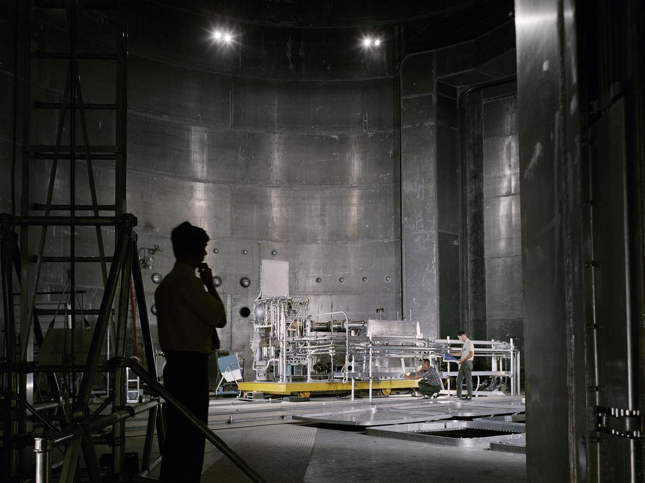
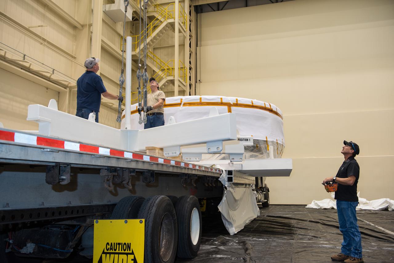
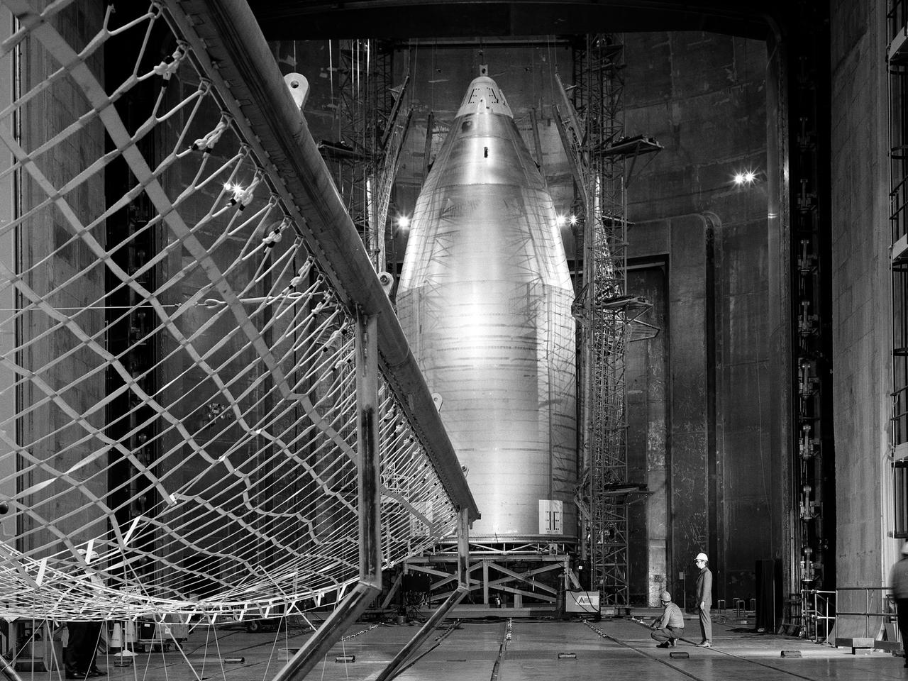
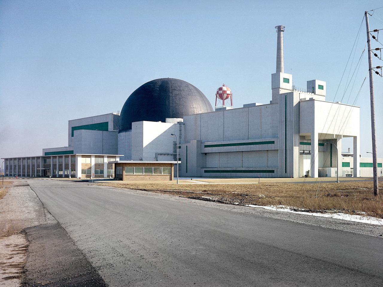
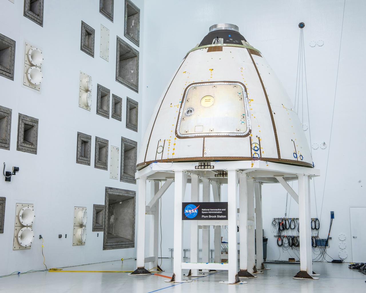
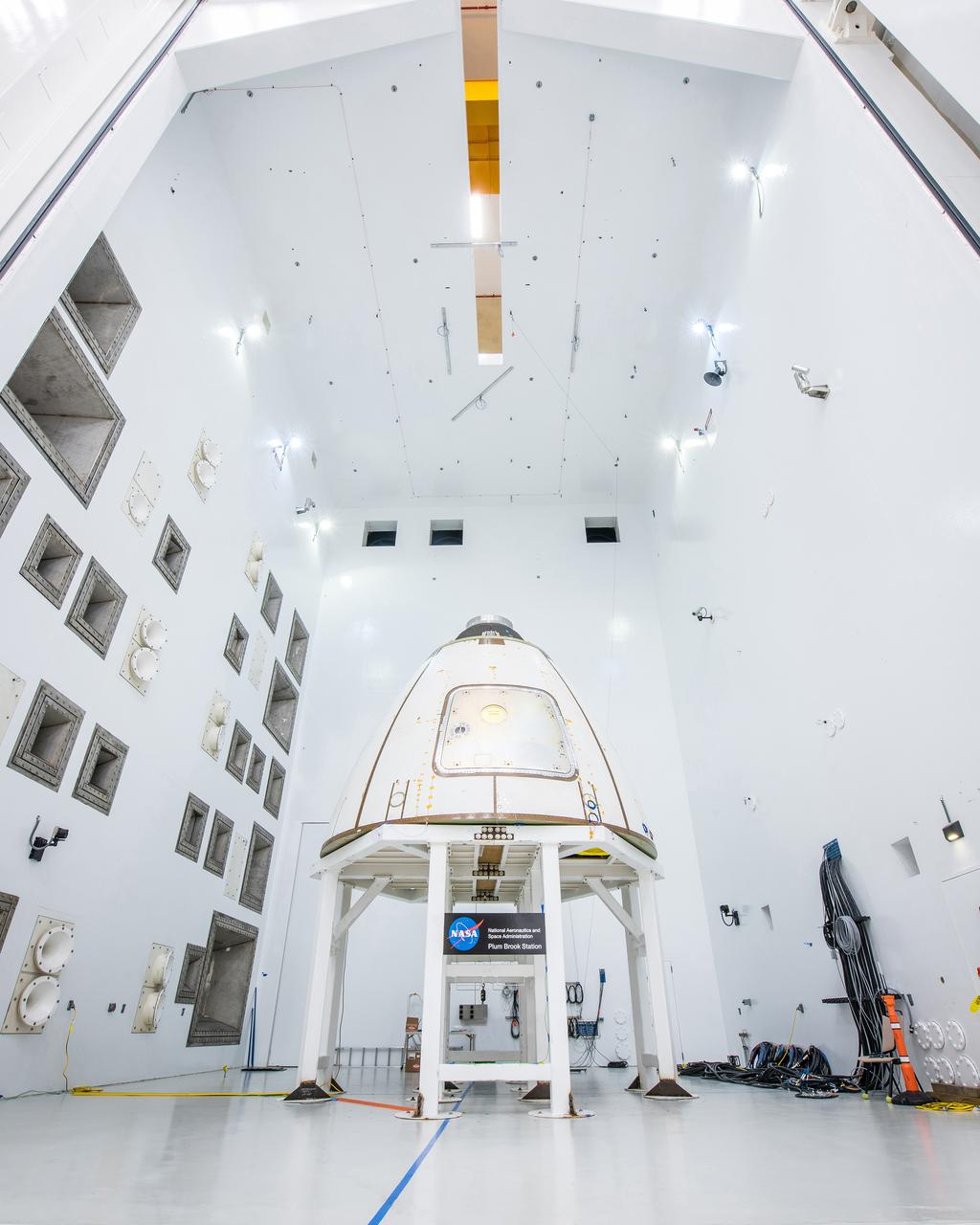
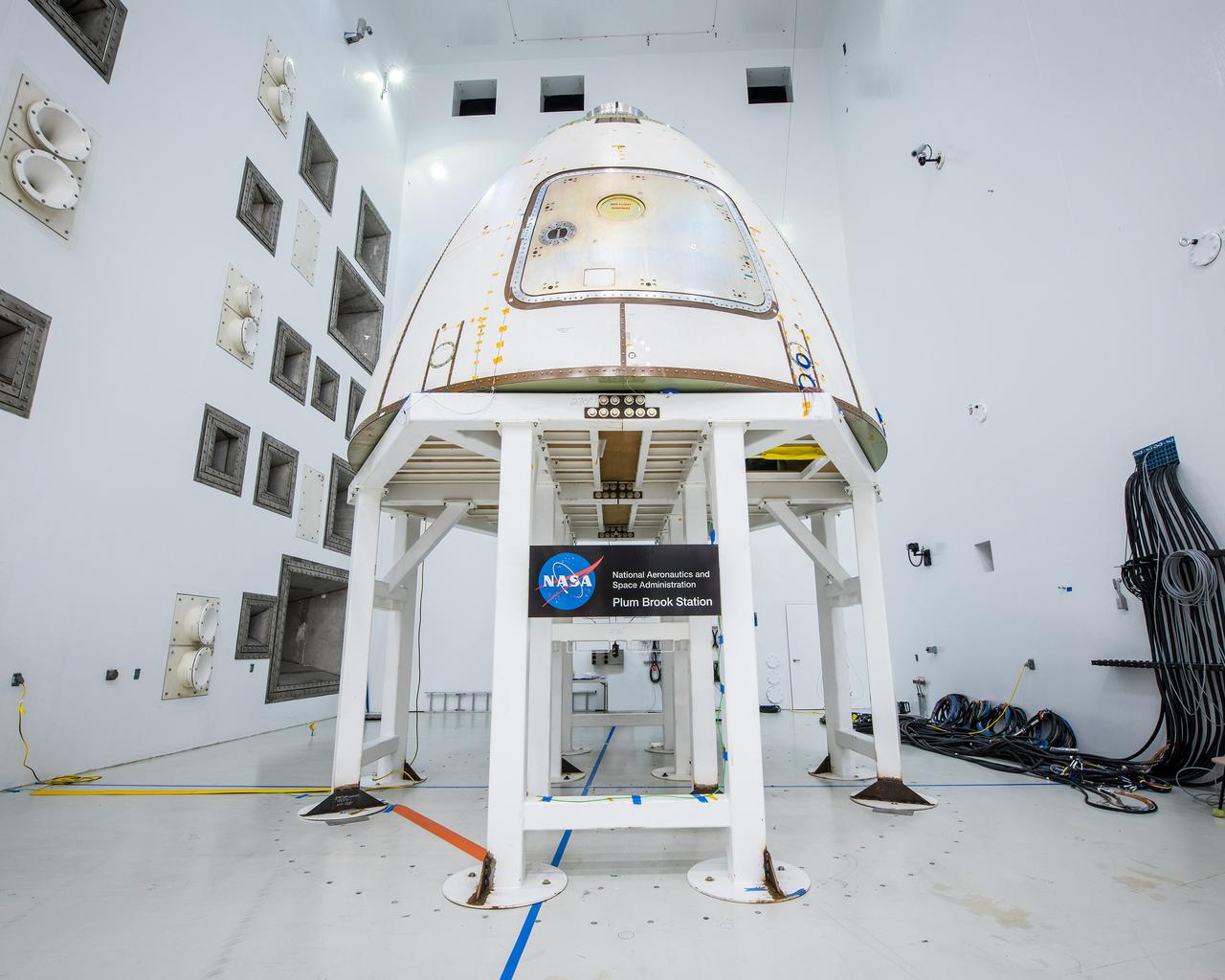
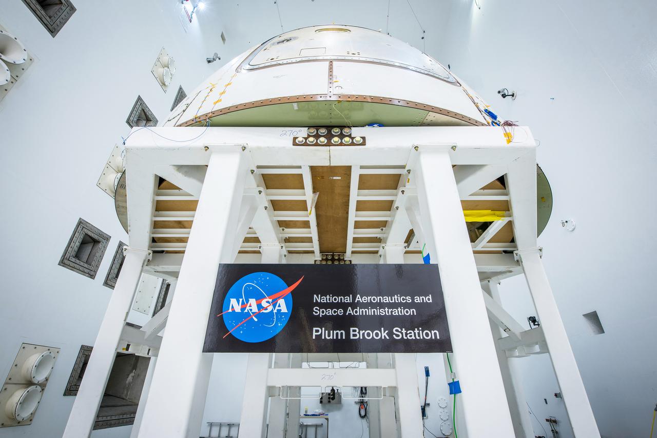
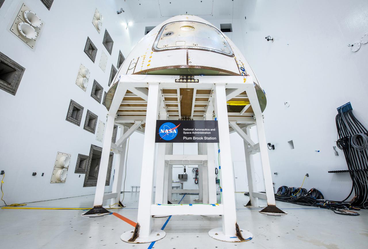
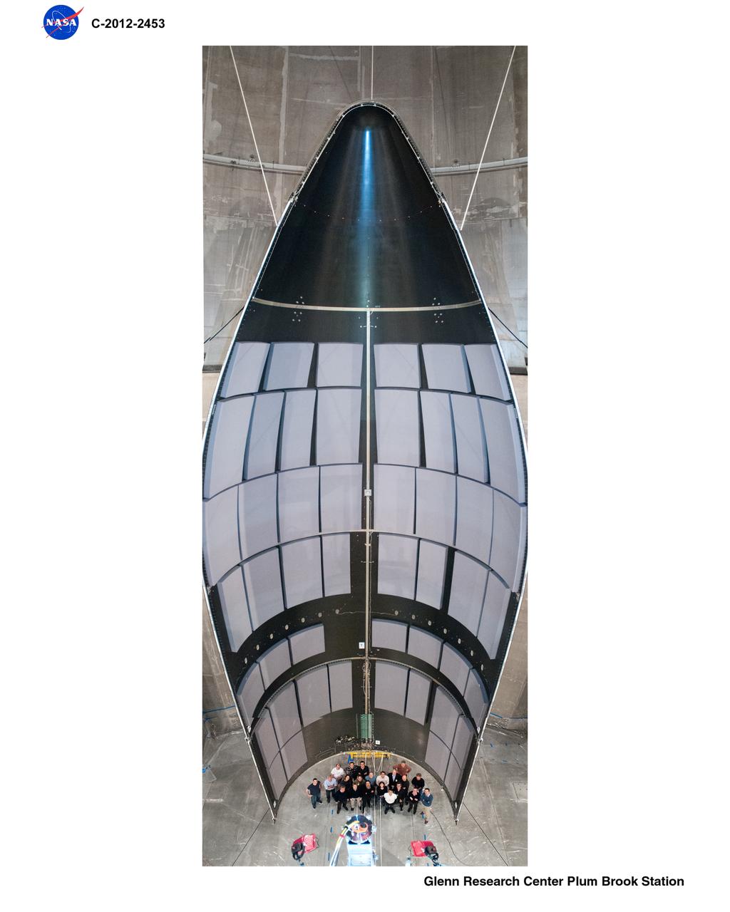
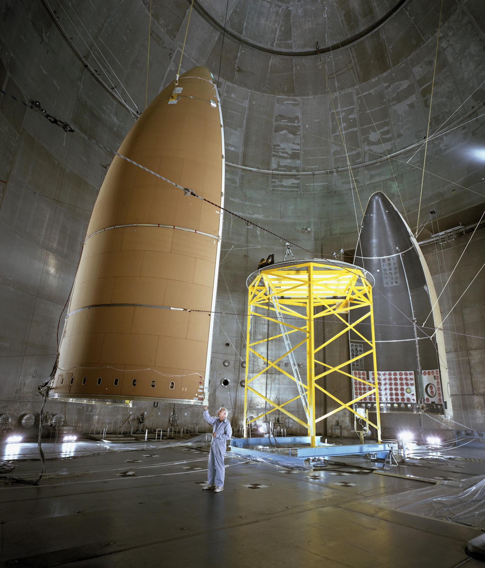
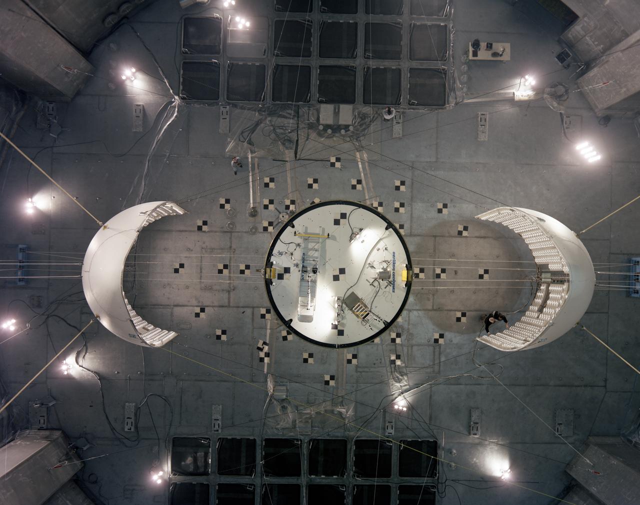
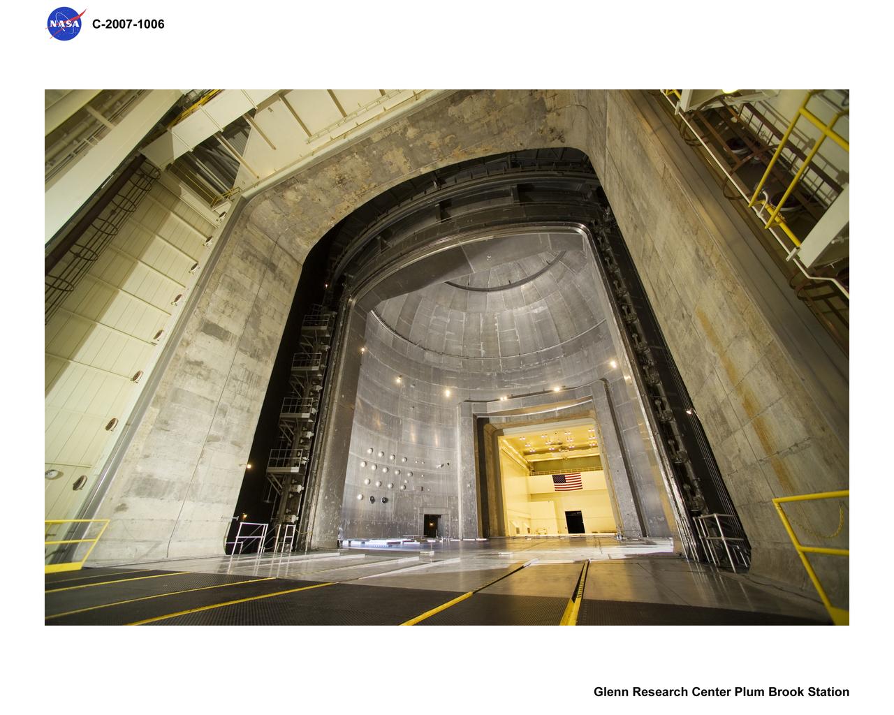
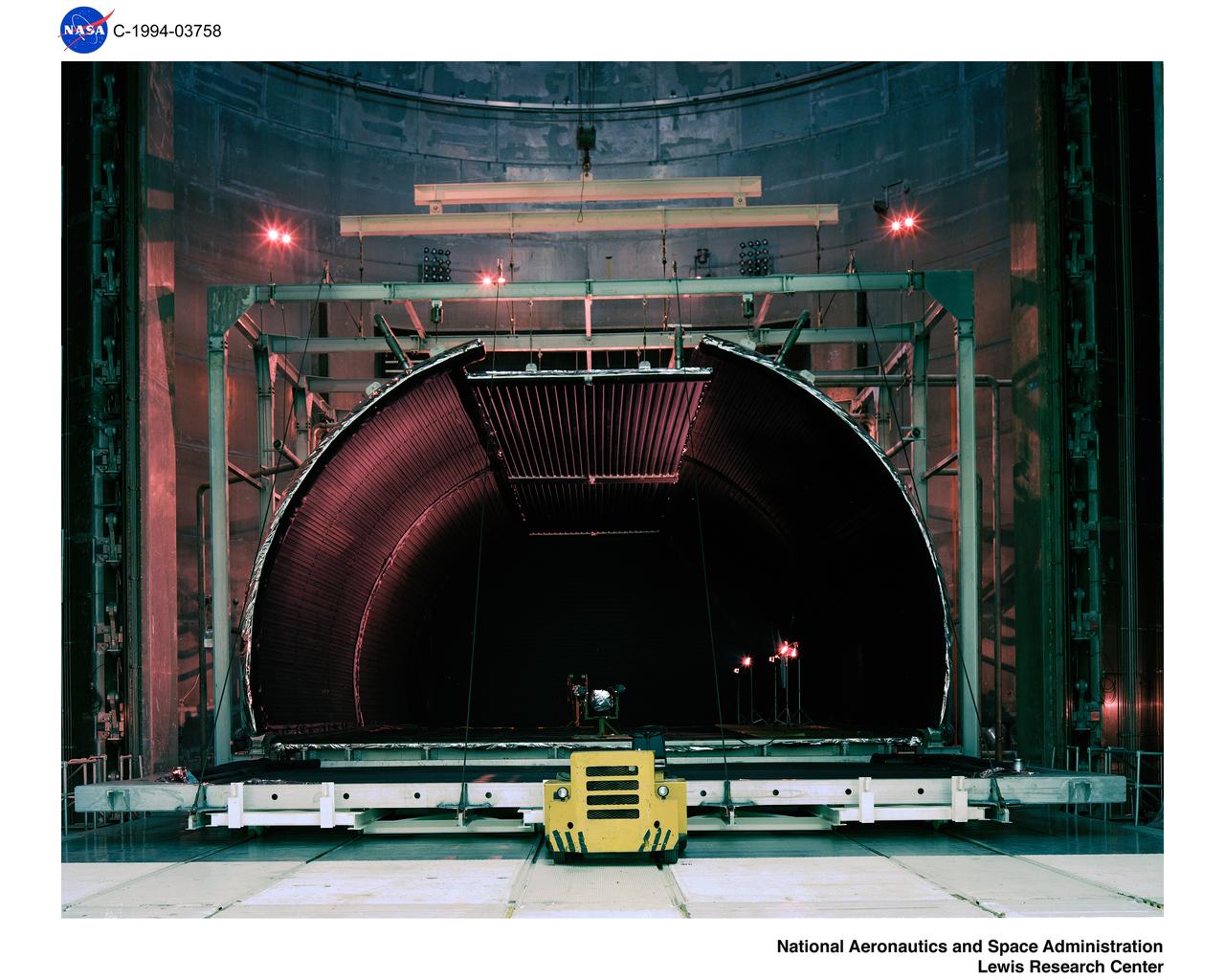
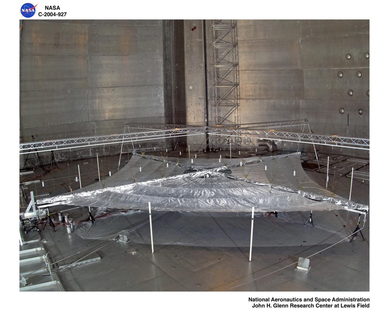
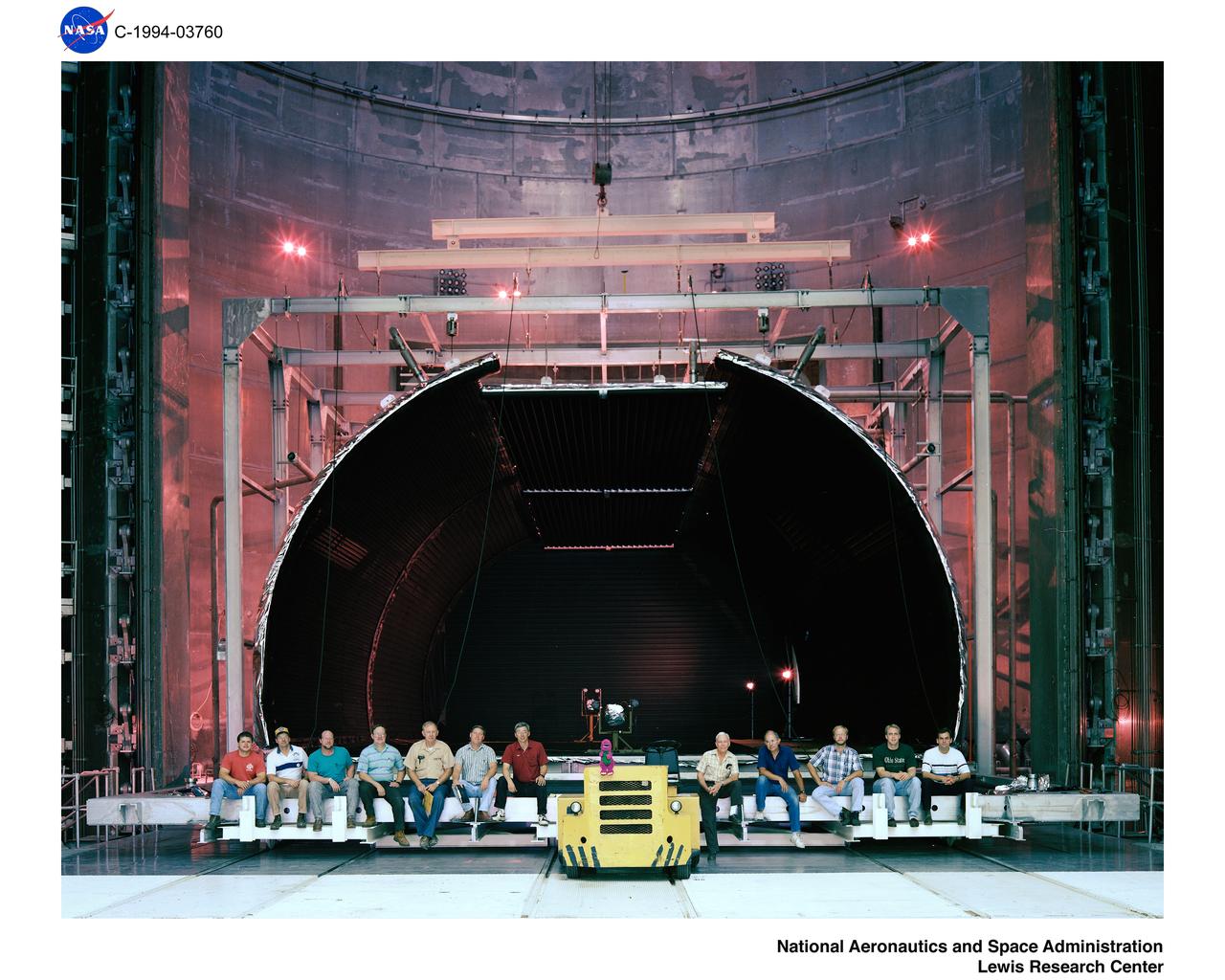
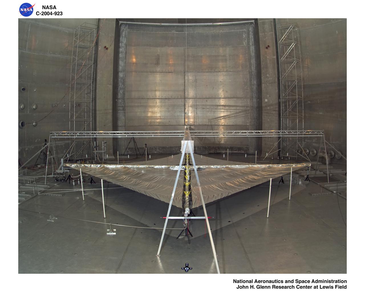
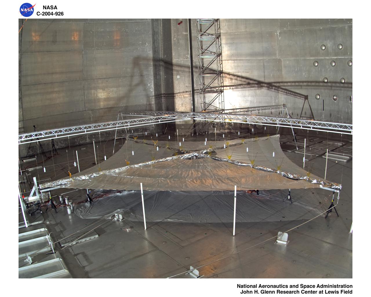
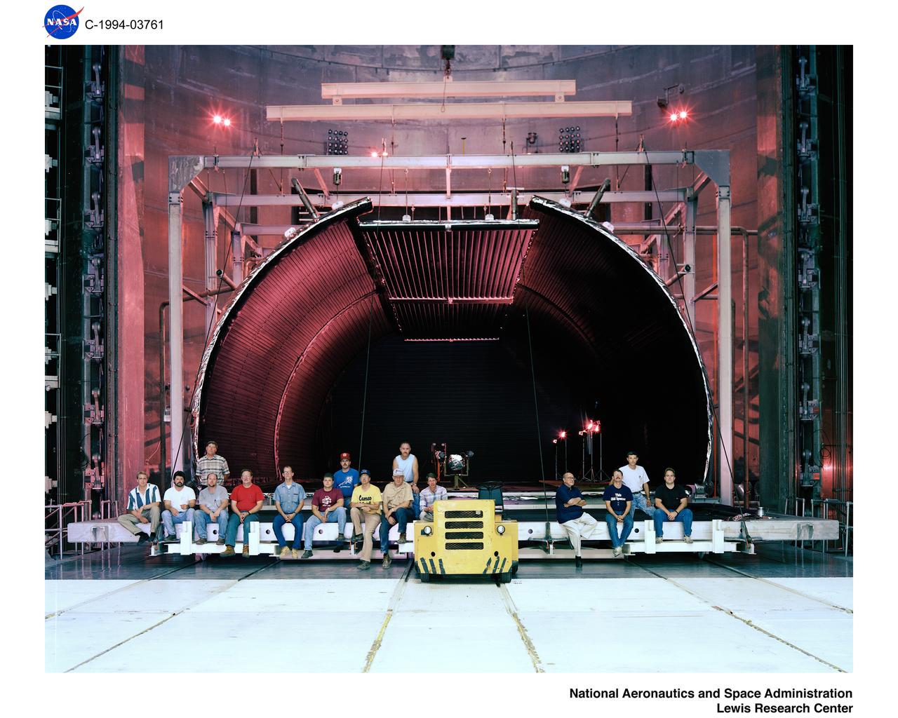
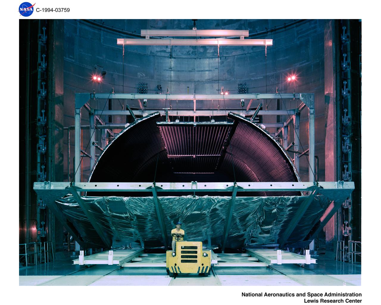
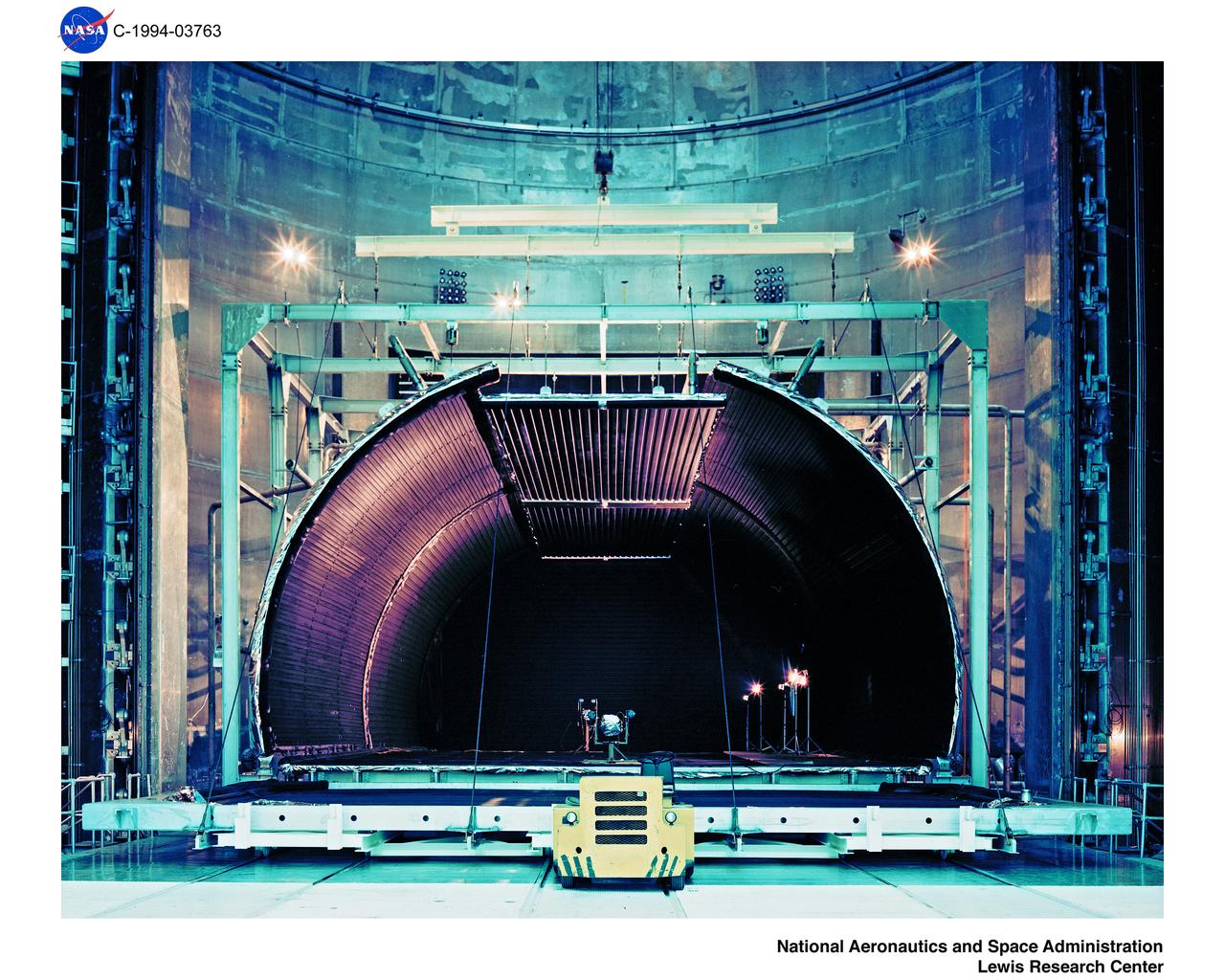
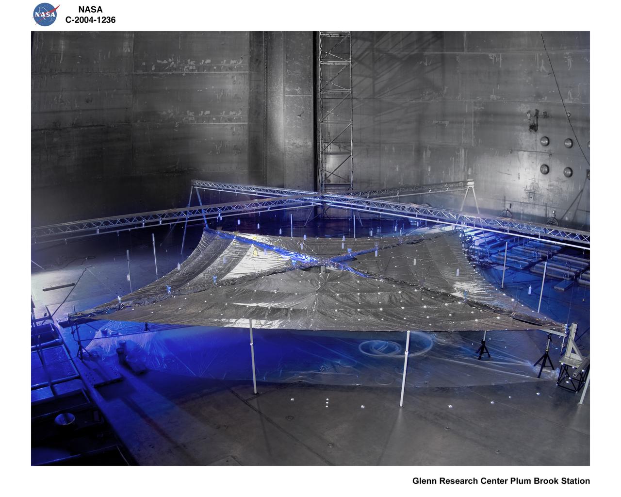
Skylab Shroud in the Space Power Facility
Exterior view of the Space Power Facility at the National Aeronautics and Space Administration’s (NASA) Plum Brook Station in Sandusky, Ohio. The $28.4-million facility, which began operations in 1969, is the largest high vacuum chamber ever built. The chamber is 100 feet in diameter and 120 feet high. It produces a vacuum deep enough to simulate the conditions at 300 miles altitude. The facility can sustain a high vacuum; simulate solar radiation via a 4-megawatt quartz heat lamp array, solar spectrum by a 400-kilowatt arc lamp, and cold environments. The Space Power Facility was originally designed to test nuclear power sources for spacecraft during long durations in a space atmosphere, but it was never used for that purpose.     The facility’s first test in 1970 involved a 15 to 20-kilowatt Brayton Cycle Power System for space applications. Three different methods of simulating solar heat were employed during the Brayton tests. The facility was also used for jettison tests of the Centaur Standard Shroud. The shroud was designed for the new Titan-Centaur rocket that was scheduled to launch the Viking spacecraft to Mars. The new shroud was tested under conditions that simulated the time from launch to the separation of the stages.  Test programs at the facility include high-energy experiments, shroud separation tests, Mars Lander system tests, deployable Solar Sail tests and International Space Station hardware tests.
Space Power Facility at NASA’s Plum Brook Station
The ogive panels protect Orion's crew module from harsh acoustic conditions at launch and in case of an abort. Acoustic testing of the ogive hatch starts today at Space Power Facility at NASA Glenn Research Center's Plum Brook station in Sandusky, Ohio takes place on July 19, 2017. The ogive is installed in the Reverberant Acoustic Chamber where it will be blasted with 161 db of sound to simulate launch conditions.
Ogive acoustic testing starts at Space Power Facility
The Centaur Standard Shroud prepared for a jettison test in the Space Power Facility at the National Aeronautics and Space Administration’s (NASA) Plum Brook Station. In the late 1960s NASA engineers were planning the ambitious new Viking mission to send two rover vehicles to the surface of Mars. The Viking rovers were the heaviest payloads ever attempted by the Centaur second-stage rocket. Each Viking was over three times the weight of the Atlas-Centaur’s previous heaviest payload. Consequently, NASA engineers sought to mate the Centaur with the more powerful Titan III booster for the launches. General Dynamics created a new version of the Centaur, D-1T, specifically for Titan.     The D-1T’s most significant modification was a completely new shroud designed by Lockheed, called the Centaur Standard Shroud. The conical two-piece covering encapsulated the payload to protect it against adverse conditions and improve the aerodynamics as the launch vehicle passed through the atmosphere. The shroud would be jettisoned when the vehicle reached the edge of space.    A string of tests were conducted in Plum Brook’s Nuclear Rocket Dynamics and Control Facility (B-3) during 1973 and 1974. The new shroud performed flawlessly during the actual Viking launches in 1975. Viking 1 and 2 operated on the Martian surface until November 1982 and April 1980, respectively.
Centaur Standard Shroud Test in the Space Power Facility
Space Power Facility at Plum Brook Station, RUAG Ariane 5 Shroud Separation Tests. GRC has the world's largest vacuum chamber in the world.  This world class facility is host to many space launch vehicle systems tests from customer's in this country and from around the world.  Shown here is the post test of a successful rocket shroud separation test.  The shroud, or top of a rocket, is jettisoned into two halves with explosive charges to allow the payload to be exposed  for deployment.  The payload, often time is a satellite, would be sitting atop the center white section shown in the middle of the photo.  This photo was taken from on top of the rocket holding the payload and both halves of the rocket shroud looking down at one of the shroud halves and the test crew at the bottom.
GRC-2012-C-02453
At the Payload Hazardous Servicing Facility at NASA Kennedy Space Center in Florida, the back shell powered descent vehicle configuration of NASA Mars Science Laboratory is being rotated for final closeout actions.
Final Closeout Actions for Curiosity Heat Shield and Back Shell
The powered descent vehicle of NASA Mars Science Laboratory spacecraft is being prepared for final integration into the spacecraft back shell in this photograph from inside the Payload Hazardous Servicing Facility at NASA Kennedy Space Center, Fla.
Integrating Powered Descent Vehicle with Back Shell of Mars Spacecraft
At the Payload Hazardous Servicing Facility at NASA Kennedy Space Center in Florida, the back shell powered descent vehicle configuration, containing NASA Mars Science Laboratory rover, Curiosity, is being placed on the spacecraft heat shield.
Connecting Curiosity Heat Shield and Back Shell
An engineer says goodbye to the Curiosity rover and its powered descent vehicle in the Jet Propulsion Laboratory Spacecraft Assembly Facility shortly before the spacecraft was readied for shipment to Kennedy Space Center for launch.
Fish-eye View of NASA Curiosity Rover and its Powered Descent Vehicle
At the Payload Hazardous Servicing Facility at NASA Kennedy Space Center in Florida, the back shell powered descent vehicle configuration of NASA Mars Science Laboratory is being rotated for final closeout actions.
Rotating Curiosity Back Shell Powered Descent Vehicle
Top down photograph showing separation of the Ariane V fairing after testing in the vacuum chamber at SEC
GRC-1994-C-05154
KENNEDY SPACE CENTER, FLA. -  In the Space Station Processing Facility, Japanese astronaut Koichi Wakata (top left) and technicians watch as a tray is extended from inside the Pressurized Module, or PM, part of the Japanese Experiment Module (JEM).   The PM provides a shirt-sleeve environment in which astronauts on the International Space Station can conduct microgravity experiments. There are a total of 23 racks, including 10 experiment racks, inside the PM providing a power supply, communications, air conditioning, hardware cooling, water control and experiment support functions.
KENNEDY SPACE CENTER, FLA. - In the Space Station Processing Facility, Japanese astronaut Koichi Wakata (top left) and technicians watch as a tray is extended from inside the Pressurized Module, or PM, part of the Japanese Experiment Module (JEM). The PM provides a shirt-sleeve environment in which astronauts on the International Space Station can conduct microgravity experiments. There are a total of 23 racks, including 10 experiment racks, inside the PM providing a power supply, communications, air conditioning, hardware cooling, water control and experiment support functions.
KENNEDY SPACE CENTER, FLA. - In the Space Station Processing Facility, Japanese astronaut Koichi Wakata looks over the Pressurized Module, or PM, part of the Japanese Experiment Module (JEM).  The PM provides a shirt-sleeve environment in which astronauts on the International Space Station can conduct microgravity experiments. There are a total of 23 racks, including 10 experiment racks, inside the PM providing a power supply, communications, air conditioning, hardware cooling, water control and experiment support functions.
KENNEDY SPACE CENTER, FLA. - In the Space Station Processing Facility, Japanese astronaut Koichi Wakata looks over the Pressurized Module, or PM, part of the Japanese Experiment Module (JEM). The PM provides a shirt-sleeve environment in which astronauts on the International Space Station can conduct microgravity experiments. There are a total of 23 racks, including 10 experiment racks, inside the PM providing a power supply, communications, air conditioning, hardware cooling, water control and experiment support functions.
KENNEDY SPACE CENTER, FLA. - In the Space Station Processing Facility, technicians on the floor watch as a tray is extended from inside the Pressurized Module, or PM, part of the Japanese Experiment Module (JEM).   The PM provides a shirt-sleeve environment in which astronauts on the International Space Station can conduct microgravity experiments. There are a total of 23 racks, including 10 experiment racks, inside the PM providing a power supply, communications, air conditioning, hardware cooling, water control and experiment support functions.
KENNEDY SPACE CENTER, FLA. - In the Space Station Processing Facility, technicians on the floor watch as a tray is extended from inside the Pressurized Module, or PM, part of the Japanese Experiment Module (JEM). The PM provides a shirt-sleeve environment in which astronauts on the International Space Station can conduct microgravity experiments. There are a total of 23 racks, including 10 experiment racks, inside the PM providing a power supply, communications, air conditioning, hardware cooling, water control and experiment support functions.
NASA Curiosity rover and its rocket-powered descent vehicle pose for a portrait at JPL Spacecraft Assembly Facility prior to its launch on November 26, 2011 from the Space Launch Complex 41 on Cape Canaveral Air Force Station in Florida.
3-D Anaglyph Fish-eye View of NASA Curiosity Rover and its Rocket-Powered Descent Vehicle
Teams at NASA’s Michoud Assembly Facility in New Orleans are preparing the core stage of the agency’s SLS (Space Launch System) for shipment to the agency’s Kennedy Space Center in Florida. The 212-foot-tall core stage and its four RS-25 engines will help power Artemis II, the first crewed mission of NASA’s Artemis campaign. Crews removed the external access stands, or scaffolding, in preparation for moving the rocket hardware to another area of the facility.
NASA Teams Prepare Artemis II Rocket Stage for Shipment
Teams at NASA’s Michoud Assembly Facility in New Orleans are preparing the core stage of the agency’s SLS (Space Launch System) for shipment to the agency’s Kennedy Space Center in Florida. The 212-foot-tall core stage and its four RS-25 engines will help power Artemis II, the first crewed mission of NASA’s Artemis campaign. Crews removed the external access stands, or scaffolding, in preparation for moving the rocket hardware to another area of the facility. Image credit: NASA/Michael DeMocker
NASA Teams Prepare Artemis II Rocket Stage for Shipment
Space Power Facility (SPF) - Test Chamber
GRC-2007-C-01006
These photos show teams at NASA’s Michoud Assembly Facility in New Orleans preparing, moving, and loading the engine section of a future SLS (Space Launch System) rocket to NASA’s Pegasus barge Aug. 28. The hardware will form the bottom-most section of the SLS core stage that will power NASA’s Artemis IV mission, which will be the first mission to the Gateway space station in lunar orbit under the Artemis campaign. The barge will transport the spaceflight hardware to NASA’s Kennedy Space Center in Florida via the agency’s Pegasus barge. Once in Florida, the engine section will undergo final outfitting inside Kennedy’s Space Station Processing Facility.
NASA, Boeing Move Artemis IV Rocket Hardware to Barge
These photos and videos show teams at NASA’s Michoud Assembly Facility in New Orleans preparing, moving, and loading the engine section of a future SLS (Space Launch System) rocket to NASA’s Pegasus barge Aug. 28. The hardware will form the bottom-most section of the SLS core stage that will power NASA’s Artemis IV mission, which will be the first mission to the Gateway space station in lunar orbit under the Artemis campaign. The barge will transport the spaceflight hardware to NASA’s Kennedy Space Center in Florida via the agency’s Pegasus barge. Once in Florida, the engine section will undergo final outfitting inside Kennedy’s Space Station Processing Facility.
NASA, Boeing Move Artemis IV Rocket Hardware to Barge
These photos show teams at NASA’s Michoud Assembly Facility in New Orleans preparing, moving, and loading the engine section of a future SLS (Space Launch System) rocket to NASA’s Pegasus barge Aug. 28. The hardware will form the bottom-most section of the SLS core stage that will power NASA’s Artemis IV mission, which will be the first mission to the Gateway space station in lunar orbit under the Artemis campaign. The barge will transport the spaceflight hardware to NASA’s Kennedy Space Center in Florida via the agency’s Pegasus barge. Once in Florida, the engine section will undergo final outfitting inside Kennedy’s Space Station Processing Facility.  Image credit: NASA/Michael DeMocker
NASA, Boeing Move Artemis IV Rocket Hardware to Barge
These photos and videos show teams at NASA’s Michoud Assembly Facility in New Orleans preparing, moving, and loading the engine section of a future SLS (Space Launch System) rocket to NASA’s Pegasus barge Aug. 28. The hardware will form the bottom-most section of the SLS core stage that will power NASA’s Artemis IV mission, which will be the first mission to the Gateway space station in lunar orbit under the Artemis campaign. The barge will transport the spaceflight hardware to NASA’s Kennedy Space Center in Florida via the agency’s Pegasus barge. Once in Florida, the engine section will undergo final outfitting inside Kennedy’s Space Station Processing Facility.
NASA, Boeing Move Artemis IV Rocket Hardware to Barge
These photos show teams at NASA’s Michoud Assembly Facility in New Orleans preparing, moving, and loading the engine section of a future SLS (Space Launch System) rocket to NASA’s Pegasus barge Aug. 28. The hardware will form the bottom-most section of the SLS core stage that will power NASA’s Artemis IV mission, which will be the first mission to the Gateway space station in lunar orbit under the Artemis campaign. The barge will transport the spaceflight hardware to NASA’s Kennedy Space Center in Florida via the agency’s Pegasus barge. Once in Florida, the engine section will undergo final outfitting inside Kennedy’s Space Station Processing Facility.  Image credit: NASA/Michael DeMocker
NASA, Boeing Move Artemis IV Rocket Hardware to Barge
These photos and videos show teams at NASA’s Michoud Assembly Facility in New Orleans preparing, moving, and loading the engine section of a future SLS (Space Launch System) rocket to NASA’s Pegasus barge Aug. 28. The hardware will form the bottom-most section of the SLS core stage that will power NASA’s Artemis IV mission, which will be the first mission to the Gateway space station in lunar orbit under the Artemis campaign. The barge will transport the spaceflight hardware to NASA’s Kennedy Space Center in Florida via the agency’s Pegasus barge. Once in Florida, the engine section will undergo final outfitting inside Kennedy’s Space Station Processing Facility.
NASA, Boeing Move Artemis IV Rocket Hardware to Barge
These photos show teams at NASA’s Michoud Assembly Facility in New Orleans preparing, moving, and loading the engine section of a future SLS (Space Launch System) rocket to NASA’s Pegasus barge Aug. 28. The hardware will form the bottom-most section of the SLS core stage that will power NASA’s Artemis IV mission, which will be the first mission to the Gateway space station in lunar orbit under the Artemis campaign. The barge will transport the spaceflight hardware to NASA’s Kennedy Space Center in Florida via the agency’s Pegasus barge. Once in Florida, the engine section will undergo final outfitting inside Kennedy’s Space Station Processing Facility.  Image credit: NASA/Michael DeMocker
NASA, Boeing Move Artemis IV Rocket Hardware to Barge
These photos and videos show teams at NASA’s Michoud Assembly Facility in New Orleans preparing, moving, and loading the engine section of a future SLS (Space Launch System) rocket to NASA’s Pegasus barge Aug. 28. The hardware will form the bottom-most section of the SLS core stage that will power NASA’s Artemis IV mission, which will be the first mission to the Gateway space station in lunar orbit under the Artemis campaign. The barge will transport the spaceflight hardware to NASA’s Kennedy Space Center in Florida via the agency’s Pegasus barge. Once in Florida, the engine section will undergo final outfitting inside Kennedy’s Space Station Processing Facility.
NASA, Boeing Move Artemis IV Rocket Hardware to Barge
These photos show teams at NASA’s Michoud Assembly Facility in New Orleans preparing, moving, and loading the engine section of a future SLS (Space Launch System) rocket to NASA’s Pegasus barge Aug. 28. The hardware will form the bottom-most section of the SLS core stage that will power NASA’s Artemis IV mission, which will be the first mission to the Gateway space station in lunar orbit under the Artemis campaign. The barge will transport the spaceflight hardware to NASA’s Kennedy Space Center in Florida via the agency’s Pegasus barge. Once in Florida, the engine section will undergo final outfitting inside Kennedy’s Space Station Processing Facility.  Image credit: NASA/Michael DeMocker
NASA, Boeing Move Artemis IV Rocket Hardware to Barge
Arrival and Unloading of the Mechanical Vibration Facility Table Hardware at Space Power Facility, SPF
GRC-2014-C-06689
Arrival and Unloading of the Mechanical Vibration Facility Table Hardware at Space Power Facility, SPF
GRC-2014-C-06702
CAPE CANAVERAL, Fla.  –    This photo shows the area within NASA's Kennedy Space Center where a solar photovoltaic power generation system will be built as the result of an agreement between NASA and Florida Power & Light.  The agreement is part of a new initiative that will cut reliance on fossil fuels and improve the environment by reducing greenhouse gas emissions.  The major facility will produce an estimated 10 megawatts of electrical power, which can serve roughly 3,000 homes.  A separate one-megawatt solar power facility will support the electrical needs of the center.
KSC-08pd1831
CAPE CANAVERAL, Fla.  –    This map shows the area within NASA's Kennedy Space Center where a solar photovoltaic power generation system will be built as the result of an agreement between NASA and Florida Power & Light. The agreement is part of a new initiative that will cut reliance on fossil fuels and improve the environment by reducing greenhouse gas emissions.  The major facility will produce an estimated 10 megawatts of electrical power, which can serve roughly 3,000 homes.  A separate one-megawatt solar power facility will support the electrical needs of the center.
KSC-08pd1832
CAPE CANAVERAL, Fla.  –   This photo shows the area within NASA's Kennedy Space Center where a solar photovoltaic power generation system will be built as the result of an agreement between NASA and Florida Power & Light. The agreement is part of a new initiative that will cut reliance on fossil fuels and improve the environment by reducing greenhouse gas emissions.  The major facility will produce an estimated 10 megawatts of electrical power, which can serve roughly 3,000 homes.  A separate one-megawatt solar power facility will support the electrical needs of the center.
KSC-08pd1830
CAPE CANAVERAL, Fla.  –   This map shows the two sites within NASA's Kennedy Space Center where a solar photovoltaic power generation system will be built as the result of an agreement between NASA and Florida Power & Light.  The agreement is part of a new initiative that will cut reliance on fossil fuels and improve the environment by reducing greenhouse gas emissions.  The major facility will produce an estimated 10 megawatts of electrical power, which can serve roughly 3,000 homes.  A separate one-megawatt solar power facility will support the electrical needs of the center.
KSC-08pd1834
CAPE CANAVERAL, Fla.  –  This map shows the two sites within NASA's Kennedy Space Center where a solar photovoltaic power generation system will be built as the result of an agreement between NASA and Florida Power & Light. The agreement is part of a new initiative that will cut reliance on fossil fuels and improve the environment by reducing greenhouse gas emissions.  The major facility will produce an estimated 10 megawatts of electrical power, which can serve roughly 3,000 homes.  A separate one-megawatt solar power facility will support the electrical needs of the center.
KSC-08pd1833
CRYOSHROUD STORAGE (INSIDE AND DOOR OPENING) at SPACE POWER FACILITY
GRC-1994-C-03759
Solar Sail Testing at the Plum Brook Space Power Facility (SPF)
GRC-2004-C-00926
Solar Sail Testing at the NASA Plum Brook Space Power Facility (SPF)
GRC-2004-C-01236
Solar Sail Testing at the Plum Brook Space Power Facility (SPF)
GRC-2004-C-00927
CRYOSHROUD STORAGE (INSIDE AND DOOR OPENING) at SPACE POWER FACILITY
GRC-1994-C-03763
CRYOSHROUD STORAGE (INSIDE AND DOOR OPENING) at Space Power Facility
GRC-1994-C-03761
Solar Sail Testing at the Plum Brook Space Power Facility (SPF)
GRC-2004-C-00923
CRYOSHROUD STORAGE (INSIDE AND DOOR OPENING) at SPACE POWER FACILITY
GRC-1994-C-03760
CRYOSHROUD STORAGE (INSIDE AND DOOR OPENING) at SPACE POWER FACILITY
GRC-1994-C-03758
Space Power Facility, SPF Mechanical Vibration Facility, MVF, is a three-axis, 6-degree-of-freedom, servohydraulic, sinusoidal base-shake vibration system.
GRC-2015-C-05198
KENNEDY SPACE CENTER, FLA.  -  In the Orbiter Processing Facility, the processing team celebrates the  successful power-up of the orbiter Discovery.  The vehicle has been undergoing Orbiter Major Modifications in the past year, ranging from wiring, control panels and black boxes to gaseous and fluid systems tubing and components.  These systems were deserviced, disassembled, inspected, modified, reassembled, checked out and reserviced, as were most other systems onboard.  The work includes the installation of the Multifunction Electronic Display Subsystem (MEDS) - a state-of-the-art “glass cockpit.”
KENNEDY SPACE CENTER, FLA. - In the Orbiter Processing Facility, the processing team celebrates the successful power-up of the orbiter Discovery. The vehicle has been undergoing Orbiter Major Modifications in the past year, ranging from wiring, control panels and black boxes to gaseous and fluid systems tubing and components. These systems were deserviced, disassembled, inspected, modified, reassembled, checked out and reserviced, as were most other systems onboard. The work includes the installation of the Multifunction Electronic Display Subsystem (MEDS) - a state-of-the-art “glass cockpit.”
KENNEDY SPACE CENTER, FLA.  -   In the Orbiter Processing Facility, the processing team applaud the successful power-up of the orbiter Discovery.  The vehicle has been undergoing Orbiter Major Modifications in the past year, ranging from wiring, control panels and black boxes to gaseous and fluid systems tubing and components.  These systems were deserviced, disassembled, inspected, modified, reassembled, checked out and reserviced, as were most other systems onboard.  The work includes the installation of the Multifunction Electronic Display Subsystem (MEDS) - a state-of-the-art “glass cockpit.”
KENNEDY SPACE CENTER, FLA. - In the Orbiter Processing Facility, the processing team applaud the successful power-up of the orbiter Discovery. The vehicle has been undergoing Orbiter Major Modifications in the past year, ranging from wiring, control panels and black boxes to gaseous and fluid systems tubing and components. These systems were deserviced, disassembled, inspected, modified, reassembled, checked out and reserviced, as were most other systems onboard. The work includes the installation of the Multifunction Electronic Display Subsystem (MEDS) - a state-of-the-art “glass cockpit.”
KENNEDY SPACE CENTER, FLA.  -   During power-up of the orbiter Discovery in the Orbiter Processing Facility, a technician turns on a switch.  Discovery has been undergoing Orbiter Major Modifications in the past year, ranging from wiring, control panels and black boxes to gaseous and fluid systems tubing and components.  These systems were deserviced, disassembled, inspected, modified, reassembled, checked out and reserviced, as were most other systems onboard.  The work includes the installation of the Multifunction Electronic Display Subsystem (MEDS) - a state-of-the-art “glass cockpit.”
KENNEDY SPACE CENTER, FLA. - During power-up of the orbiter Discovery in the Orbiter Processing Facility, a technician turns on a switch. Discovery has been undergoing Orbiter Major Modifications in the past year, ranging from wiring, control panels and black boxes to gaseous and fluid systems tubing and components. These systems were deserviced, disassembled, inspected, modified, reassembled, checked out and reserviced, as were most other systems onboard. The work includes the installation of the Multifunction Electronic Display Subsystem (MEDS) - a state-of-the-art “glass cockpit.”
KENNEDY SPACE CENTER, FLA.  -  During power-up of the orbiter Discovery in the Orbiter Processing Facility, a technician moves a switch.  Discovery has been undergoing Orbiter Major Modifications in the past year, ranging from wiring, control panels and black boxes to gaseous and fluid systems tubing and components.  These systems were deserviced, disassembled, inspected, modified, reassembled, checked out and reserviced, as were most other systems onboard.  The work includes the installation of the Multifunction Electronic Display Subsystem (MEDS) - a state-of-the-art “glass cockpit.”
KENNEDY SPACE CENTER, FLA. - During power-up of the orbiter Discovery in the Orbiter Processing Facility, a technician moves a switch. Discovery has been undergoing Orbiter Major Modifications in the past year, ranging from wiring, control panels and black boxes to gaseous and fluid systems tubing and components. These systems were deserviced, disassembled, inspected, modified, reassembled, checked out and reserviced, as were most other systems onboard. The work includes the installation of the Multifunction Electronic Display Subsystem (MEDS) - a state-of-the-art “glass cockpit.”
KENNEDY SPACE CENTER, FLA. -  At the Astrotech Space Operations processing facilities, an overhead crane moves NASA’s MESSENGER spacecraft toward a work stand. There employees of the Johns Hopkins University Applied Physics Laboratory, builders of the spacecraft, will perform an initial state-of-health check.  Then processing for launch can begin, including checkout of the power systems, communications systems and control systems.  The thermal blankets will also be attached for flight.  MESSENGER - short for MErcury Surface, Space ENvironment, GEochemistry and Ranging - will be launched May 11 on a six-year mission aboard a Boeing Delta II rocket.  Liftoff is targeted for 2:26 a.m. EDT on Tuesday, May 11.
KENNEDY SPACE CENTER, FLA. - At the Astrotech Space Operations processing facilities, an overhead crane moves NASA’s MESSENGER spacecraft toward a work stand. There employees of the Johns Hopkins University Applied Physics Laboratory, builders of the spacecraft, will perform an initial state-of-health check. Then processing for launch can begin, including checkout of the power systems, communications systems and control systems. The thermal blankets will also be attached for flight. MESSENGER - short for MErcury Surface, Space ENvironment, GEochemistry and Ranging - will be launched May 11 on a six-year mission aboard a Boeing Delta II rocket. Liftoff is targeted for 2:26 a.m. EDT on Tuesday, May 11.
KENNEDY SPACE CENTER, FLA. -  At the Astrotech Space Operations processing facilities, NASA’s MESSENGER spacecraft is secure after transfer to the work stand. There employees of the Johns Hopkins University Applied Physics Laboratory, builders of the spacecraft, will perform an initial state-of-health check.  Then processing for launch can begin, including checkout of the power systems, communications systems and control systems.  The thermal blankets will also be attached for flight.  MESSENGER - short for MErcury Surface, Space ENvironment, GEochemistry and Ranging - will be launched May 11 on a six-year mission aboard a Boeing Delta II rocket.  Liftoff is targeted for 2:26 a.m. EDT on Tuesday, May 11.
KENNEDY SPACE CENTER, FLA. - At the Astrotech Space Operations processing facilities, NASA’s MESSENGER spacecraft is secure after transfer to the work stand. There employees of the Johns Hopkins University Applied Physics Laboratory, builders of the spacecraft, will perform an initial state-of-health check. Then processing for launch can begin, including checkout of the power systems, communications systems and control systems. The thermal blankets will also be attached for flight. MESSENGER - short for MErcury Surface, Space ENvironment, GEochemistry and Ranging - will be launched May 11 on a six-year mission aboard a Boeing Delta II rocket. Liftoff is targeted for 2:26 a.m. EDT on Tuesday, May 11.
KENNEDY SPACE CENTER, FLA. -  At the Astrotech Space Operations processing facilities, an overhead crane lowers NASA’s MESSENGER spacecraft onto a work stand. There employees of the Johns Hopkins University Applied Physics Laboratory, builders of the spacecraft, will perform an initial state-of-health check.  Then processing for launch can begin, including checkout of the power systems, communications systems and control systems.  The thermal blankets will also be attached for flight.  MESSENGER - short for MErcury Surface, Space ENvironment, GEochemistry and Ranging - will be launched May 11 on a six-year mission aboard a Boeing Delta II rocket.  Liftoff is targeted for 2:26 a.m. EDT on Tuesday, May 11.
KENNEDY SPACE CENTER, FLA. - At the Astrotech Space Operations processing facilities, an overhead crane lowers NASA’s MESSENGER spacecraft onto a work stand. There employees of the Johns Hopkins University Applied Physics Laboratory, builders of the spacecraft, will perform an initial state-of-health check. Then processing for launch can begin, including checkout of the power systems, communications systems and control systems. The thermal blankets will also be attached for flight. MESSENGER - short for MErcury Surface, Space ENvironment, GEochemistry and Ranging - will be launched May 11 on a six-year mission aboard a Boeing Delta II rocket. Liftoff is targeted for 2:26 a.m. EDT on Tuesday, May 11.
KENNEDY SPACE CENTER, FLA. -  In the high bay clean room at the Astrotech Space Operations processing facilities near KSC, NASA’s MESSENGER spacecraft is revealed.  Employees of the Johns Hopkins University Applied Physics Laboratory, builders of the spacecraft, will perform an initial state-of-health check.  Then processing for launch can begin, including checkout of the power systems, communications systems and control systems.  The thermal blankets will also be attached for flight.  MESSENGER - short for MErcury Surface, Space ENvironment, GEochemistry and Ranging - will be launched May 11 on a six-year mission aboard a Boeing Delta II rocket.  Liftoff is targeted for 2:26 a.m. EDT on Tuesday, May 11.
KENNEDY SPACE CENTER, FLA. - In the high bay clean room at the Astrotech Space Operations processing facilities near KSC, NASA’s MESSENGER spacecraft is revealed. Employees of the Johns Hopkins University Applied Physics Laboratory, builders of the spacecraft, will perform an initial state-of-health check. Then processing for launch can begin, including checkout of the power systems, communications systems and control systems. The thermal blankets will also be attached for flight. MESSENGER - short for MErcury Surface, Space ENvironment, GEochemistry and Ranging - will be launched May 11 on a six-year mission aboard a Boeing Delta II rocket. Liftoff is targeted for 2:26 a.m. EDT on Tuesday, May 11.
KENNEDY SPACE CENTER, FLA. -  In KSC's Vertical Processing Facility, Louise Kleba of the Vehicle Integration Test Team (VITT) and engineer Devin Tailor of Goddard Space Flight Center examine the Pistol Grip Tool (PGT), which was designed for use by astronauts during spacewalks.  The PGT is a self-contained, micro-processor controlled, battery-powered tool.  It also can be used as a nonpowered ratchet wrench.  The experiences of the astronauts on the first Hubble Space Telescope (HST) servicing mission led to recommendations for this smaller, more efficient tool for precision work during spacewalks.  The PGT will be used on the second HST servicing mission, STS-82.  Liftoff aboard Discovery is scheduled Feb. 11.
KENNEDY SPACE CENTER, FLA. - In KSC's Vertical Processing Facility, Louise Kleba of the Vehicle Integration Test Team (VITT) and engineer Devin Tailor of Goddard Space Flight Center examine the Pistol Grip Tool (PGT), which was designed for use by astronauts during spacewalks. The PGT is a self-contained, micro-processor controlled, battery-powered tool. It also can be used as a nonpowered ratchet wrench. The experiences of the astronauts on the first Hubble Space Telescope (HST) servicing mission led to recommendations for this smaller, more efficient tool for precision work during spacewalks. The PGT will be used on the second HST servicing mission, STS-82. Liftoff aboard Discovery is scheduled Feb. 11.