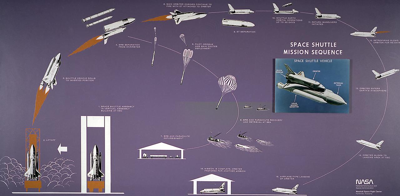
This diagram illustrates the Space Shuttle mission sequence. The Space Shuttle was approved as a national program in 1972 and developed through the 1970s. Part spacecraft and part aircraft, the Space Shuttle orbiter, the brain and the heart of the Space Transportation System (STS), required several technological advances, including thousands of insulating tiles able to stand the heat of reentry over the course of many missions, as well as sophisticated engines that could be used again and again without being thrown away. The airplane-like orbiter has three main engines, that burn liquid hydrogen and oxygen stored in the large external tank, the single largest structure in the Shuttle. Attached to the tank are two solid rocket boosters that provide the vehecile with most of the thrust needed for liftoff. Two minutes into the flight, the spent solids drop into the ocean to be recovered and refurbished for reuse, while the orbiter engines continue burning until approximately 8 minutes into the flight. After the mission is completed, the orbiter lands on a runway like an airplane.
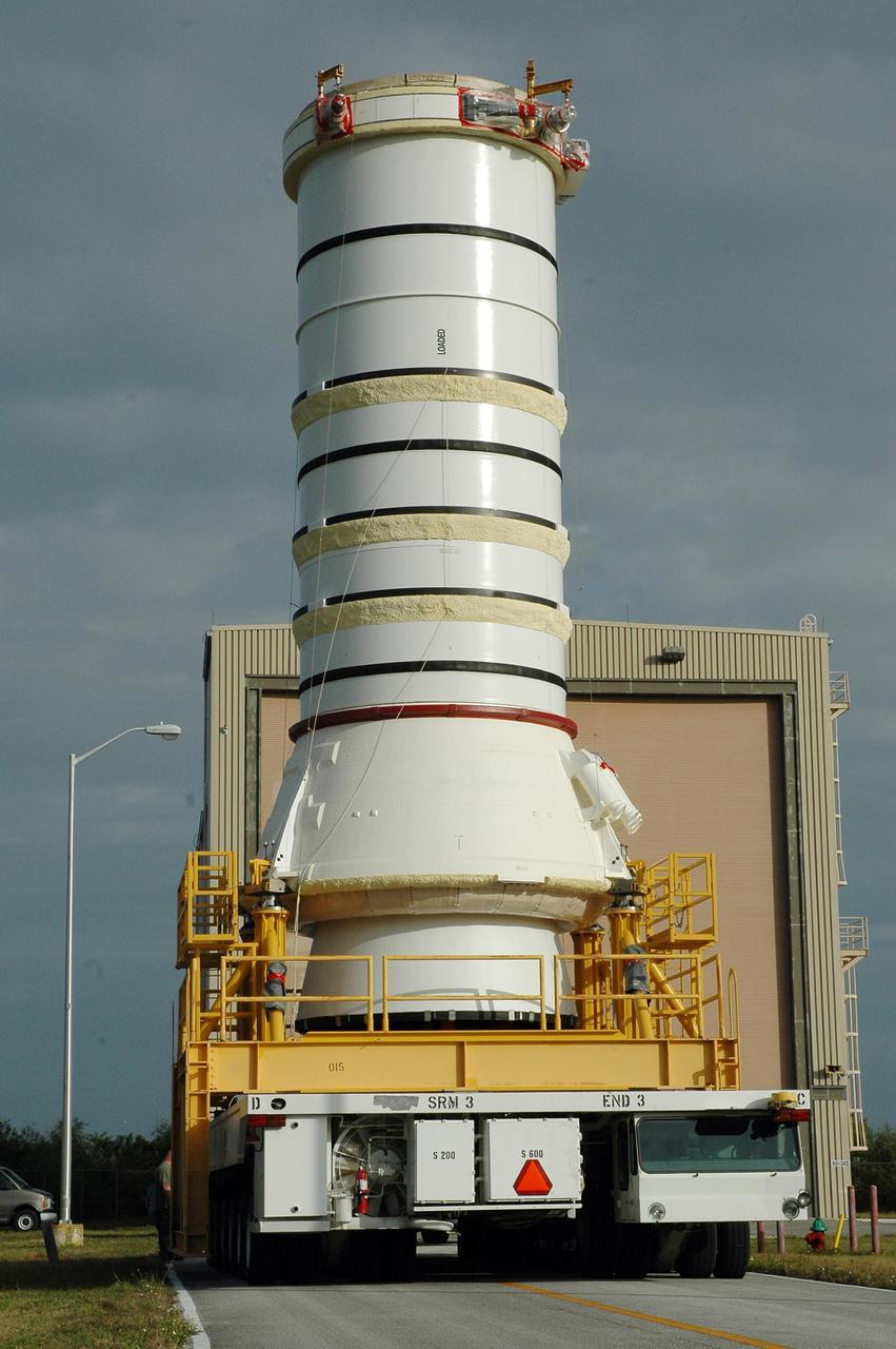
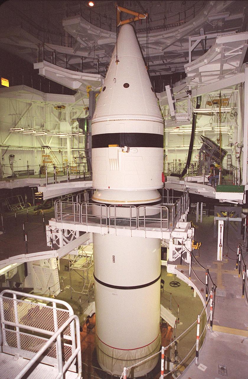
KENNEDY SPACE CENTER, FLA. — The right aft booster, comprised of the aft skirt and the aft motor segment, leaves the Rotation Processing and Surge Facility for transfer to the Vehicle Assembly Building where it will be lifted onto the mobile launcher platform. The booster is being assembled for the space shuttle Discovery on mission STS-121, the second space shuttle mission in the return-to-flight sequence. The booster assembly is a major milestone in the processing sequence that leads to launch. The launch date is targeted no earlier than May. Photo credit: NASA/Jack Pfaller

KENNEDY SPACE CENTER, FLA. — The right aft booster, comprised of the aft skirt and the aft motor segment, rolls into the transfer aisle of the Vehicle Assembly Building where it will be lifted onto the mobile launcher platform. The booster is being assembled for the space shuttle Discovery on mission STS-121, the second space shuttle mission in the return-to-flight sequence. The booster assembly is a major milestone in the processing sequence that leads to launch. The launch date is targeted no earlier than May. Photo credit: NASA/Jack Pfaller
KENNEDY SPACE CENTER, FLA. — The right aft booster, comprised of the aft skirt and the aft motor segment, is ready to be lifted onto the mobile launcher platform inside the Vehicle Assembly Building. The booster is being assembled for the space shuttle Discovery on mission STS-121, the second space shuttle mission in the return-to-flight sequence. The booster assembly is a major milestone in the processing sequence that leads to launch. The launch date is targeted no earlier than May. Photo credit: NASA/Jack Pfaller
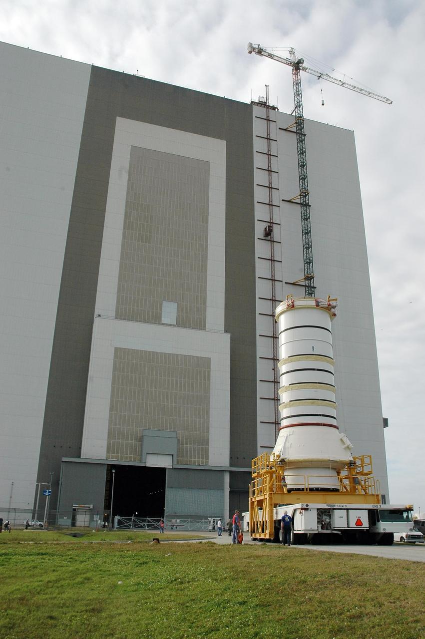
KENNEDY SPACE CENTER, FLA. — The right aft booster, comprised of the aft skirt and the aft motor segment, rolls toward the Vehicle Assembly Building where it will be lifted onto the mobile launcher platform. The booster is being assembled for the space shuttle Discovery on mission STS-121, the second space shuttle mission in the return-to-flight sequence. The booster assembly is a major milestone in the processing sequence that leads to launch. The launch date is targeted no earlier than May. Photo credit: NASA/Jack Pfaller

KENNEDY SPACE CENTER, FLA. — The right aft booster, comprised of the aft skirt and the aft motor segment, rolls toward the open door of the Vehicle Assembly Building where it will be lifted onto the mobile launcher platform. The booster is being assembled for the space shuttle Discovery on mission STS-121, the second space shuttle mission in the return-to-flight sequence. The booster assembly is a major milestone in the processing sequence that leads to launch. The launch date is targeted no earlier than May. Photo credit: NASA/Jack Pfaller
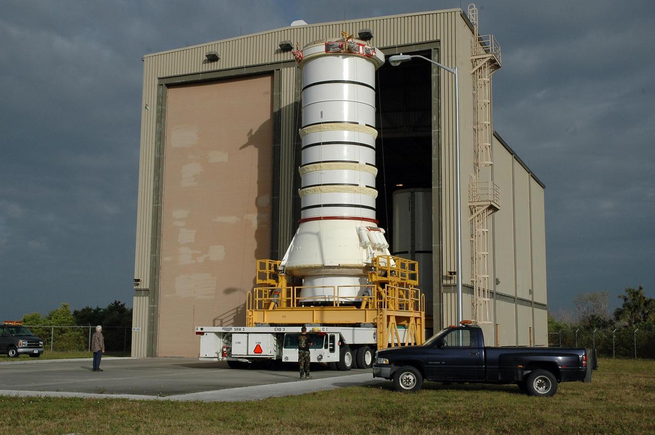
KENNEDY SPACE CENTER, FLA. — The right aft booster, comprised of the aft skirt and the aft motor segment, rolls out of the Rotation Processing and Surge Facility for transfer to the Vehicle Assembly Building where it will be lifted onto the mobile launcher platform. The booster is being assembled for the space shuttle Discovery on mission STS-121, the second space shuttle mission in the return-to-flight sequence. The booster assembly is a major milestone in the processing sequence that leads to launch. The launch date is targeted no earlier than May. Photo credit: NASA/Jack Pfaller

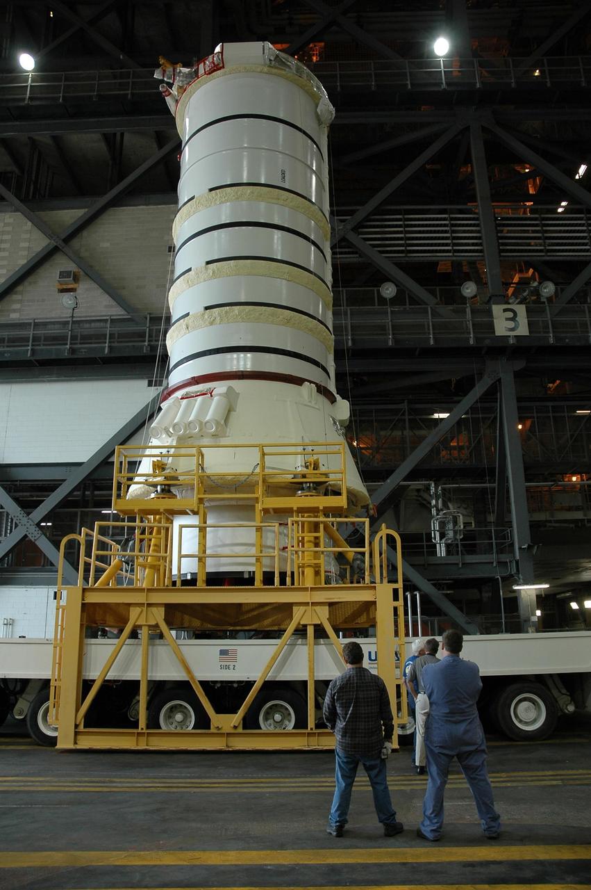
KENNEDY SPACE CENTER, FLA. — In the Vehicle Assembly Building at NASA Kennedy Space Center, an overhead crane lifts the right aft booster segments (aft skirt and aft motor segment) to be used with space shuttle Discovery on mission STS-121. The segments will be installed on the mobile launcher platform in Bay 3. Mission STS-121 is the second space shuttle mission in the return-to-flight sequence. The booster assembly is a major milestone in the processing sequence that leads to launch. The launch date is targeted no earlier than May. Photo credit: NASA/Jack Pfaller
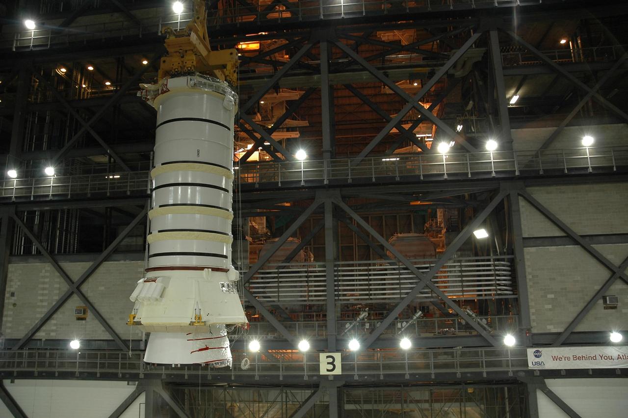
KENNEDY SPACE CENTER, FLA. — In the Vehicle Assembly Building at NASA Kennedy Space Center, an overhead crane lifts the right aft booster segments (aft skirt and aft motor segment). The segments, to be used with space shuttle Discovery on mission STS-121, will be installed on the mobile launcher platform in Bay 3.Mission STS-121 is the second space shuttle mission in the return-to-flight sequence. The booster assembly is a major milestone in the processing sequence that leads to launch. The launch date is targeted no earlier than May. Photo credit: NASA/Jack Pfaller
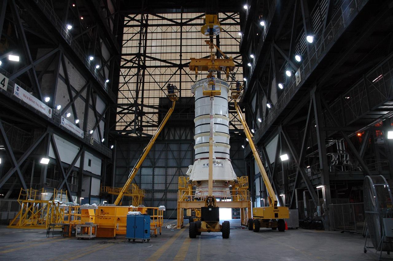
KENNEDY SPACE CENTER, FLA. — The right aft booster segments (aft skirt and aft motor segment) to be used with space shuttle Discovery on mission STS-121 are fitted with a crane in the Vehicle Assembly Building at NASA Kennedy Space Center. The crane will lift the mated segments and install them on the mobile launcher platform in Bay 3. Mission STS-121 is the second space shuttle mission in the return-to-flight sequence. The booster assembly is a major milestone in the processing sequence that leads to launch. The launch date is targeted no earlier than May. Photo credit: NASA/Jack Pfaller
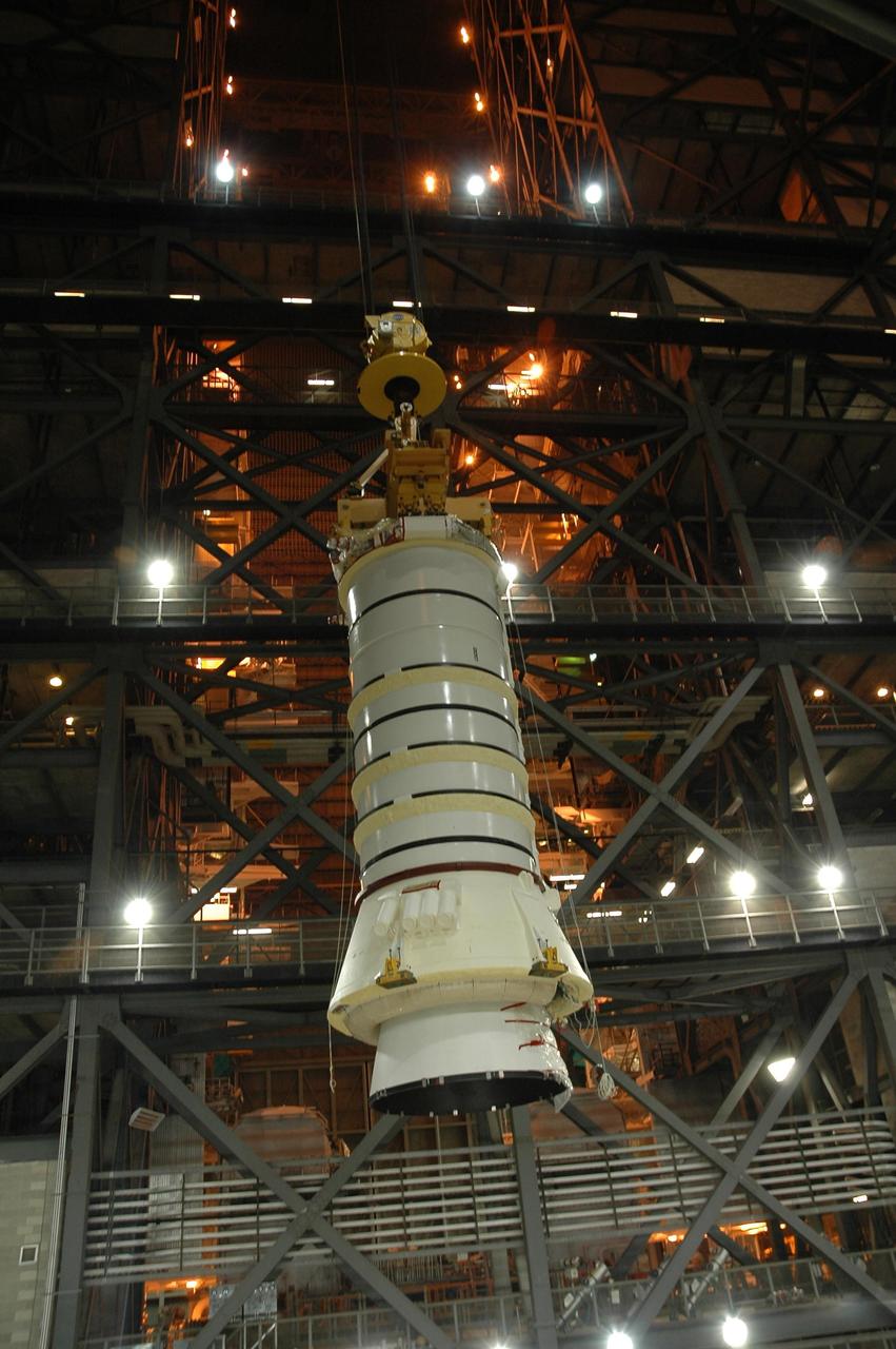
KENNEDY SPACE CENTER, FLA. — In the Vehicle Assembly Building at NASA Kennedy Space Center, the right aft booster segments (aft skirt and aft motor segment) near the point where they will be moved over into the high bay and lowered onto the mobile launcher platform in Bay 3. The segments are being stacked for use with space shuttle Discovery on mission STS-121. Mission STS-121 is the second space shuttle mission in the return-to-flight sequence. The booster assembly is a major milestone in the processing sequence that leads to launch. The launch date is targeted no earlier than May. Photo credit: NASA/Jack Pfaller

KENNEDY SPACE CENTER, FLA. — In the Vehicle Assembly Building at NASA Kennedy Space Center, the right aft booster segments (aft skirt and aft motor segment) cross over into the high bay where the mobile launcher platform is waiting in Bay 3. The segments will be stacked for use with space shuttle Discovery on mission STS-121. Mission STS-121 is the second space shuttle mission in the return-to-flight sequence. The booster assembly is a major milestone in the processing sequence that leads to launch. The launch date is targeted no earlier than May. Photo credit: NASA/Jack Pfaller
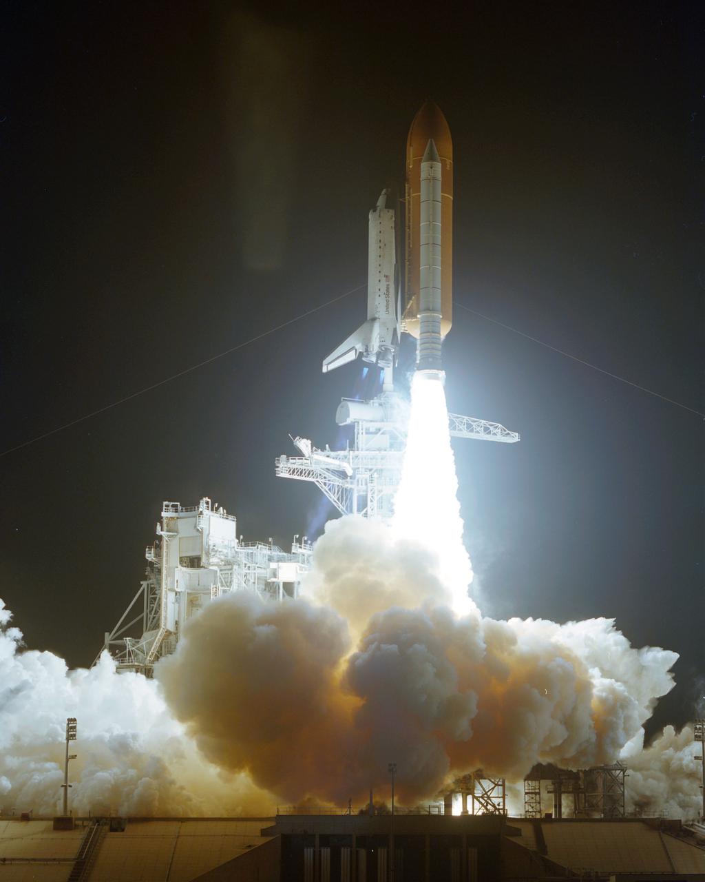
STS063-S-007 (3 Feb 1995) --- The race to catch up with the Russia's Mir gets underway as the Space Shuttle Discovery launches from Pad 39B, Kennedy Space Center (KSC) at 12:22:04 (EST), February 3, 1995. Discovery is the first in the current fleet of four Space Shuttle vehicles to make 20 launches. Onboard for the 67th (STS-63 is out of sequence) Shuttle flight are astronauts James D. Wetherbee, mission commander; Eileen M. Collins, pilot; Bernard A. Harris Jr., payload commander; mission specialists Janice Voss and C. Michael Foale; along with Russian cosmonaut Vladimir G. Titov.
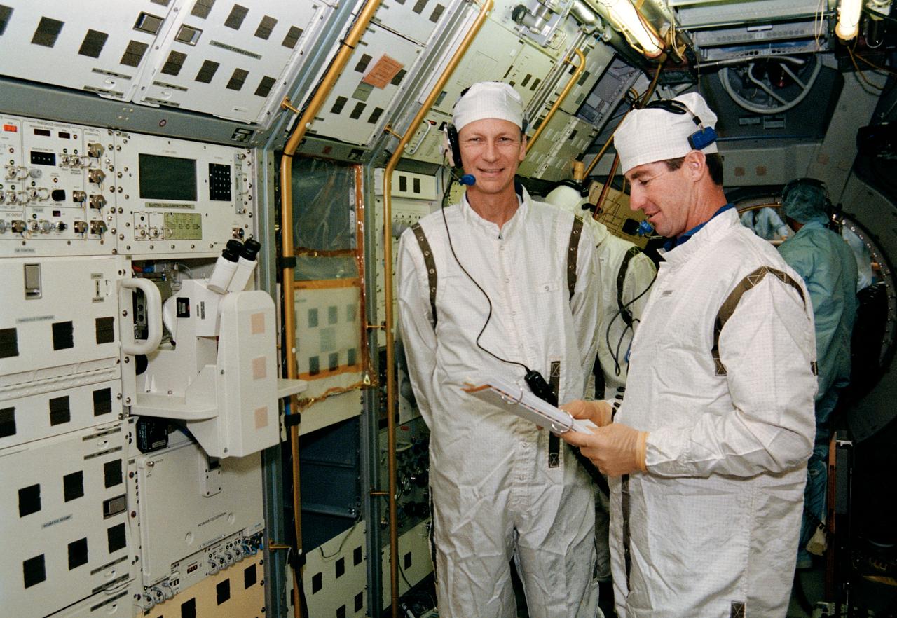
S93-29830 (4 Nov 1992) --- Inside the Spacelab D-2 module in the Operations and Checkout Building high bay, STS-55 Mission Commander Steven R. Nagel (left) and Pilot Terence T. Henricks are participating in a mission sequence test to check out experiment steps and procedures which will be conducted on-orbit. Spacelab D-2, the second German Spacelab, is scheduled to fly on space shuttle mission STS-55 in 1993.
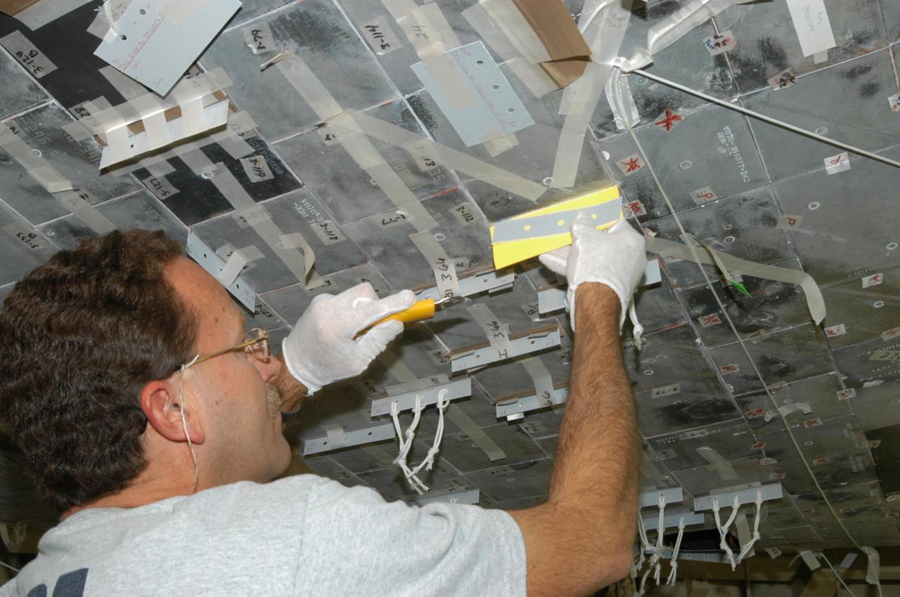
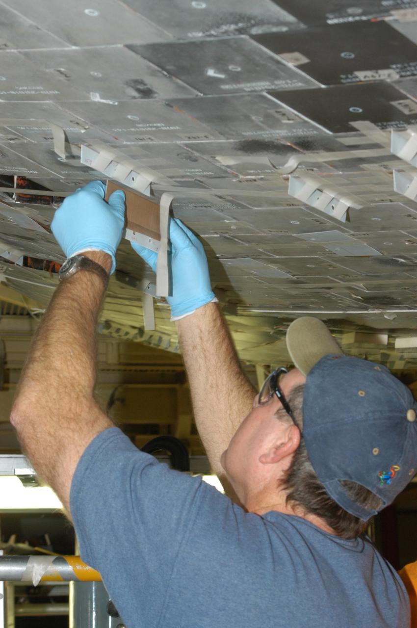
KENNEDY SPACE CENTER, FLA. -- United Space Alliance technician Gene Peavler removes the excess gap filler he cut away from the tile on the orbiter Discovery, which is being processed in Orbiter Processing Facility Bay 3 at NASA’s Kennedy Space Center. This work is being performed due to two gap fillers that were protruding from the underside of Discovery on the first Return to Flight mission, STS-114. New installation procedures have been developed to ensure the gap fillers stay in place and do not pose any hazard during the shuttle's re-entry to the atmosphere. Discovery is the scheduled orbiter for the second space shuttle mission in the return-to-flight sequence.
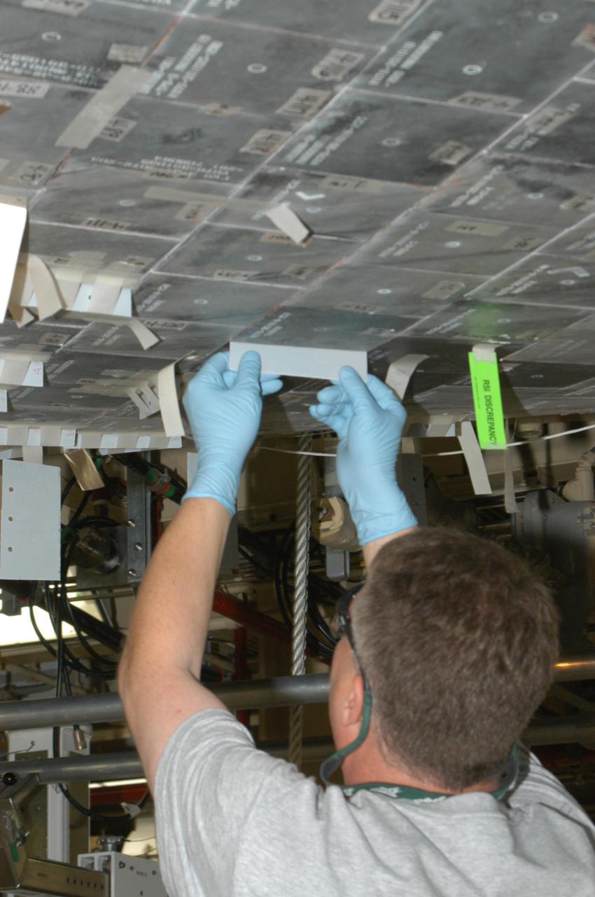
KENNEDY SPACE CENTER, FLA. -- United Space Alliance technician Larry Tanner makes a fit check on the piece of gap filler to be installed on the orbiter Discovery, which is being processed in Orbiter Processing Facility Bay 3 at NASA’s Kennedy Space Center. This work is being performed due to two gap fillers that were protruding from the underside of Discovery on the first Return to Flight mission, STS-114. New installation procedures have been developed to ensure the gap fillers stay in place and do not pose any hazard during the shuttle's re-entry to the atmosphere. Discovery is the scheduled orbiter for the second space shuttle mission in the return-to-flight sequence.
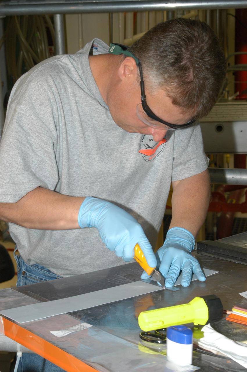
KENNEDY SPACE CENTER, FLA. -- United Space Alliance technician Larry Tanner cuts the strip of gap filler to be installed on the orbiter Discovery, which is being processed in Orbiter Processing Facility Bay 3 at NASA’s Kennedy Space Center. This work is being performed due to two gap fillers that were protruding from the underside of Discovery on the first Return to Flight mission, STS-114. New installation procedures have been developed to ensure the gap fillers stay in place and do not pose any hazard during the shuttle's re-entry to the atmosphere. Discovery is the scheduled orbiter for the second space shuttle mission in the return-to-flight sequence.

KENNEDY SPACE CENTER, FLA. -- United Space Alliance technician Larry Tanner uses a contour tool to determine the fit needed for the gap filler against the orbiter’s frame. Discovery is being processed in Orbiter Processing Facility Bay 3 at NASA’s Kennedy Space Center. This work is being performed due to two gap fillers that were protruding from the underside of Discovery on the first Return to Flight mission, STS-114. New installation procedures have been developed to ensure the gap fillers stay in place and do not pose any hazard during the shuttle's re-entry to the atmosphere. Discovery is the scheduled orbiter for the second space shuttle mission in the return-to-flight sequence.
KENNEDY SPACE CENTER, FLA. -- United Space Alliance technician Larry Tanner pulls strips of gap filler to install on the orbiter Discovery, which is being processed in Orbiter Processing Facility Bay 3 at NASA’s Kennedy Space Center. This work is being performed due to two gap fillers that were protruding from the underside of Discovery on the first Return to Flight mission, STS-114. New installation procedures have been developed to ensure the gap fillers stay in place and do not pose any hazard during the shuttle's re-entry to the atmosphere. Discovery is the scheduled orbiter for the second space shuttle mission in the return-to-flight sequence.
KENNEDY SPACE CENTER, FLA. -- United Space Alliance technician Gene Peavler cuts the excess gap filler away from the tile on the orbiter Discovery, which is being processed in Orbiter Processing Facility Bay 3 at NASA’s Kennedy Space Center. This work is being performed due to two gap fillers that were protruding from the underside of Discovery on the first Return to Flight mission, STS-114. New installation procedures have been developed to ensure the gap fillers stay in place and do not pose any hazard during the shuttle's re-entry to the atmosphere. Discovery is the scheduled orbiter for the second space shuttle mission in the return-to-flight sequence.
KENNEDY SPACE CENTER, FLA. -- United Space Alliance technician Larry Tanner places a strip of gap filler on the tile of Discovery’s underbelly to measure it for installation. Discovery is being processed in Orbiter Processing Facility Bay 3 at NASA’s Kennedy Space Center. This work is being performed due to two gap fillers that were protruding from the underside of Discovery on the first Return to Flight mission, STS-114. New installation procedures have been developed to ensure the gap fillers stay in place and do not pose any hazard during the shuttle's re-entry to the atmosphere. Discovery is the scheduled orbiter for the second space shuttle mission in the return-to-flight sequence.

KENNEDY SPACE CENTER, FLA. -- United Space Alliance technician Dell Chapman applies the Teflon-coated fabric to the gap filler before installation on the orbiter Discovery, which is being processed in Orbiter Processing Facility Bay 3 at NASA’s Kennedy Space Center. This work is being performed due to two gap fillers that were protruding from the underside of Discovery on the first Return to Flight mission, STS-114. New installation procedures have been developed to ensure the gap fillers stay in place and do not pose any hazard during the shuttle's re-entry to the atmosphere. Discovery is the scheduled orbiter for the second space shuttle mission in the return-to-flight sequence.
KENNEDY SPACE CENTER, FLA. -- United Space Alliance technician Dell Chapman installs the gap filler between tiles on the orbiter Discovery, which is being processed in Orbiter Processing Facility Bay 3 at NASA’s Kennedy Space Center. This work is being performed due to two gap fillers that were protruding from the underside of Discovery on the first Return to Flight mission, STS-114. New installation procedures have been developed to ensure the gap fillers stay in place and do not pose any hazard during the shuttle's re-entry to the atmosphere. Discovery is the scheduled orbiter for the second space shuttle mission in the return-to-flight sequence.
KENNEDY SPACE CENTER, FLA. -- United Space Alliance technician Shane Colvin prepares to cut the excess gap filler from the tile on the orbiter Discovery, which is being processed in Orbiter Processing Facility Bay 3 at NASA’s Kennedy Space Center. This work is being performed due to two gap fillers that were protruding from the underside of Discovery on the first Return to Flight mission, STS-114. New installation procedures have been developed to ensure the gap fillers stay in place and do not pose any hazard during the shuttle's re-entry to the atmosphere. Discovery is the scheduled orbiter for the second space shuttle mission in the return-to-flight sequence.
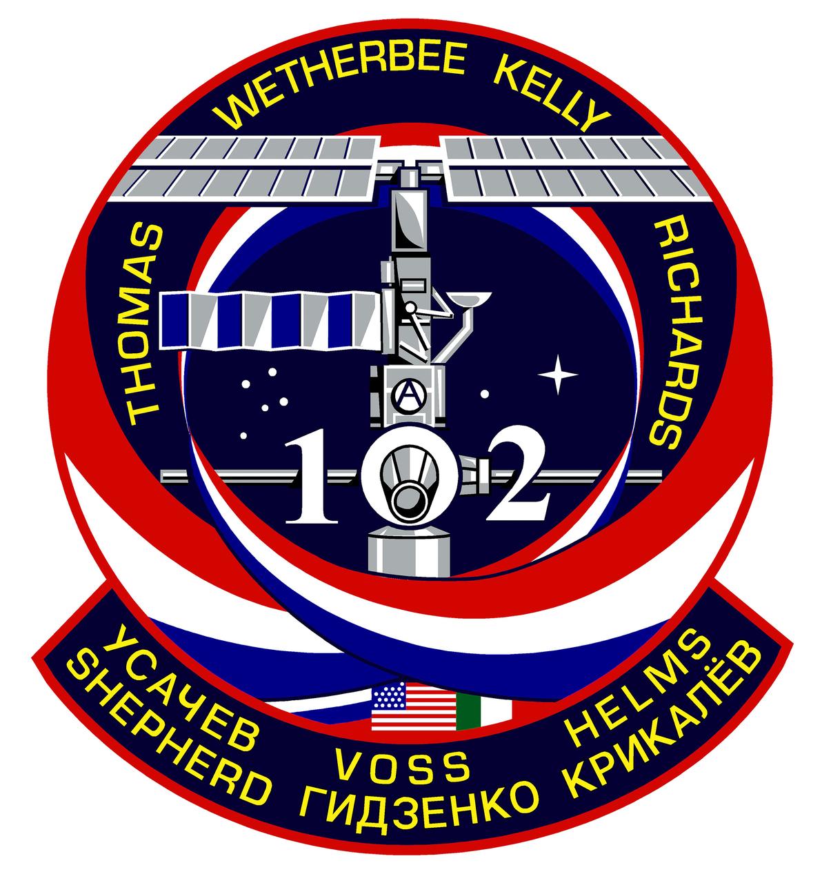
This is the STS-102 mission crew insignia. The central image on the crew patch depicts the International Space Station (ISS) in the build configuration that it had at the time of the arrival and docking of Discovery during the STS-102 mission, the first crew exchange flight to the Space Station. The station is shown along the direction of the flight as was seen by the shuttle crew during their final approach and docking, the so-called V-bar approach. The names of the shuttle crew members are depicted in gold around the top of the patch, and surnames of the Expedition crew members being exchanged are shown in the lower barner. The three ribbons swirling up to and around the station signify the rotation of these ISS crew members. The number 2 is for the Expedition 2 crew who flew up to the station, and the number 1 is for the Expedition 1 crew who then returned down to Earth. In conjunction with the face of the Lab module of the Station, these Expedition numbers create the shuttle mission number 102. Shown mated below the ISS is the Italian-built Multipurpose Logistics Module, Leonardo, that flew for the first time on this flight. The flags of the countries that were the major contributors to this effort, the United States, Russia, and Italy are also shown in the lower part of the patch. The build-sequence number of this flight in the overall station assembly sequence, 5A.1, is captured by the constellations in the background.
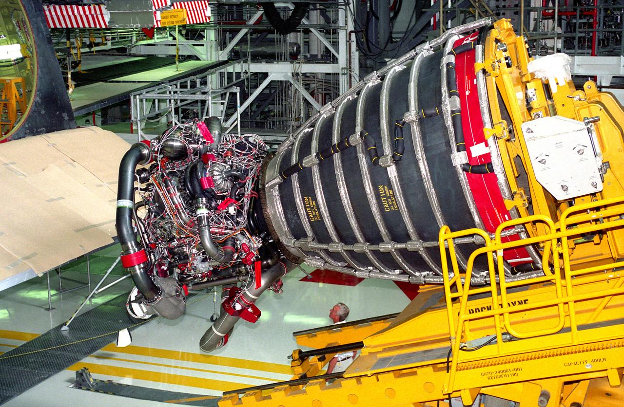
KENNEDY SPACE CENTER, FLA. - Space Shuttle Main Engine (SSME) No. 2036, the first of the new Block 1 engines to fly, awaits installation into position one of the orbiter Discovery in Orbiter Processing Facility 2 during preparation of the spaceplane for the STS-70 mission. The advanced powerplant features a new high-pressure liquid oxygen turbopump, a two-duct powerhead, a baffleless main injector, a single-coil heat exchanger and start sequence modifications. These modifications are designed to improve both engine performance and safety.
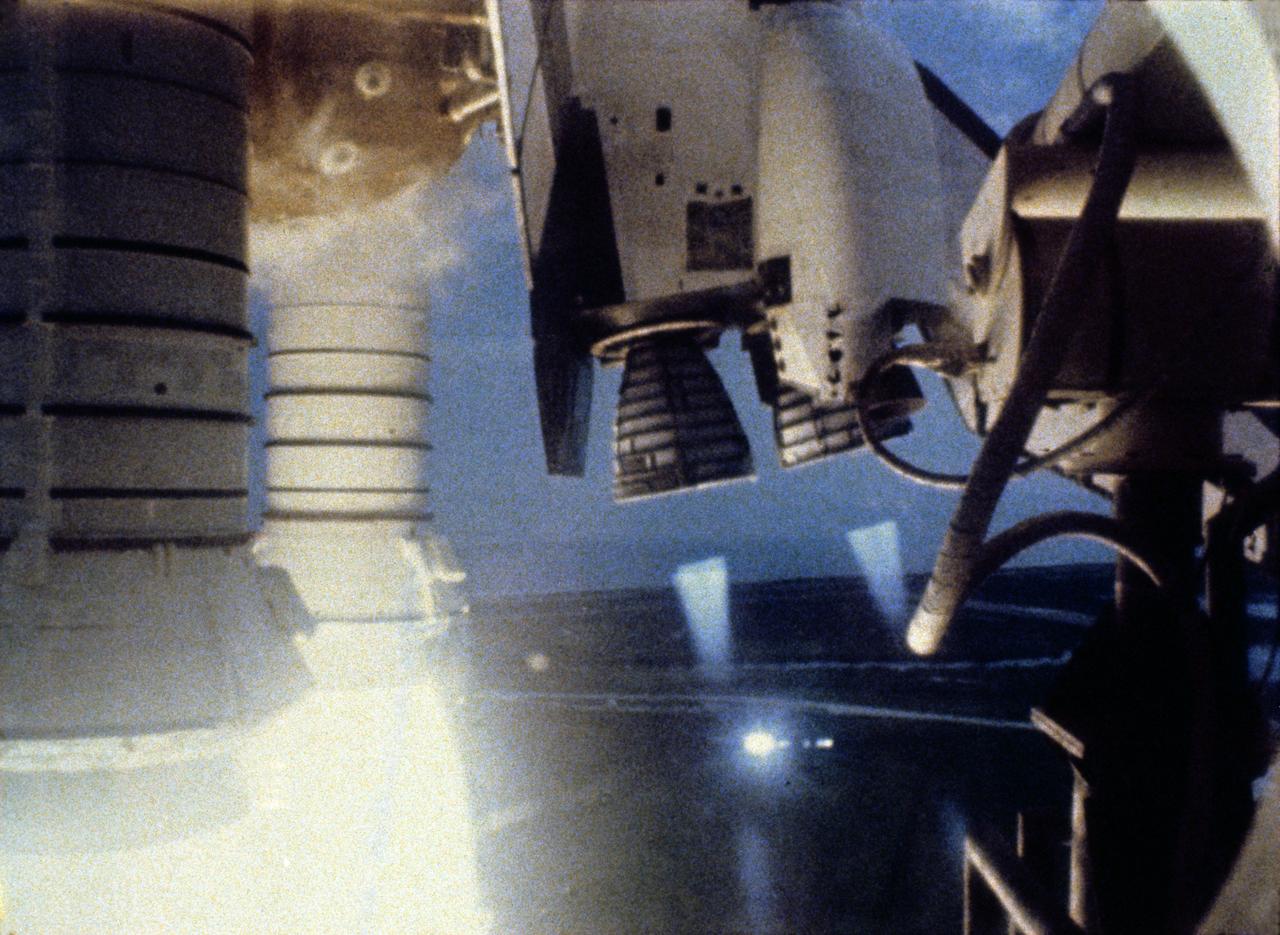
S82-28757 (22 March 1982) --- This close-up view featuring the space shuttle Columbia?s main engines and solid rocket boosters (SRB) was captured on video during the launch sequence for the STS-3 mission from NASA's Kennedy Space Center (KSC). Onboard were astronauts Jack R. Lousma, commander; and C. Gordon Fullerton, pilot. Photo credit: NASA
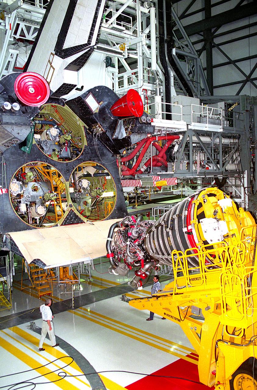
KENNEDY SPACE CENTER, FLA. - A Space Shuttle Main Engine (SSME) hoist prepares to lift the first Block 1 engine to be installed in an orbiter into the number one position on Discovery while the spaceplane is being prepared for the STS-70 mission in the high bay of Orbiter Processing Facility 2. The new engine, SSME No. 2036, features a new high-pressure liquid oxygen turbopump, a two-duct powerhead, a baffleless main injector, a single-coil heat exchanger and start sequence modifications. The other two main engines to be used during the liftoff of the STS-70 mission are of the existing Phase II design.
The STS-101 mission patch commemorates the third Space Shuttle flight supporting the assembly of the International Space Station (ISS). This flight's primary tasks were to outfit the ISS and extend its lifetime, to conduct a space walk to install external components in preparation for the docking of the Russian Service Module, Zvezda, and the arrival of the first ISS crew. The Space Shuttle is depicted in an orbit configuration prior to docking with the ISS. The ISS is depicted in the stage of assembly completed for the STS-101 mission, which consists of the United States built Unity module and the Russian-built Zarya module. The three large stars represent the third ISS mission in the assembly sequence. The elements and colors of the border reflect the flags of the nations represented by the STS-101 crew members, the United States, and Russia.
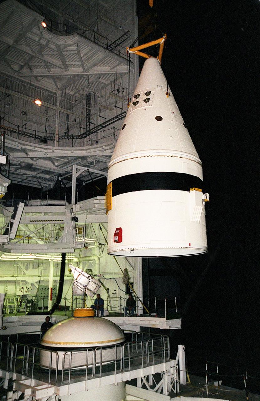
Inside the Vehicle Assembly Building, an overhead crane lifts the forward section of a solid rocket booster (SRB) to mate it with the components seen at lower left in the photo. The forward section of each booster, from nose cap to forward skirt contains avionics, a sequencer, forward separation motors, a nose cone separation system, drogue and main parachutes, a recovery beacon, a recovery light, a parachute camera on selected flights and a range safety system. Each SRB weighs approximately 1.3 million pounds at launch. The SRB is part of the stack for Space Shuttle Discovery and the STS-92 mission, scheduled for launch Oct. 5, from Launch Pad 39A, on the fifth flight to the International Space Station

Inside the Vehicle Assembly Building, an overhead crane lifts the forward section of a solid rocket booster (SRB) to mate it with the components seen at lower left in the photo. The forward section of each booster, from nose cap to forward skirt contains avionics, a sequencer, forward separation motors, a nose cone separation system, drogue and main parachutes, a recovery beacon, a recovery light, a parachute camera on selected flights and a range safety system. Each SRB weighs approximately 1.3 million pounds at launch. The SRB is part of the stack for Space Shuttle Discovery and the STS-92 mission, scheduled for launch Oct. 5, from Launch Pad 39A, on the fifth flight to the International Space Station
Inside the Vehicle Assembly Building, an overhead crane moves the forward section of a solid rocket booster (SRB) toward the previously stacked elements at lower left in the photo. The forward section of each booster, from nose cap to forward skirt contains avionics, a sequencer, forward separation motors, a nose cone separation system, drogue and main parachutes, a recovery beacon, a recovery light, a parachute camera on selected flights and a range safety system. Each SRB weighs approximately 1.3 million pounds at launch. The SRB is part of the stack for Space Shuttle Discovery and the STS-92 mission, scheduled for launch Oct. 5, from Launch Pad 39A, on the fifth flight to the International Space Station

Inside the Vehicle Assembly Building, an overhead crane moves the forward section of a solid rocket booster (SRB) toward the previously stacked elements at lower left in the photo. The forward section of each booster, from nose cap to forward skirt contains avionics, a sequencer, forward separation motors, a nose cone separation system, drogue and main parachutes, a recovery beacon, a recovery light, a parachute camera on selected flights and a range safety system. Each SRB weighs approximately 1.3 million pounds at launch. The SRB is part of the stack for Space Shuttle Discovery and the STS-92 mission, scheduled for launch Oct. 5, from Launch Pad 39A, on the fifth flight to the International Space Station
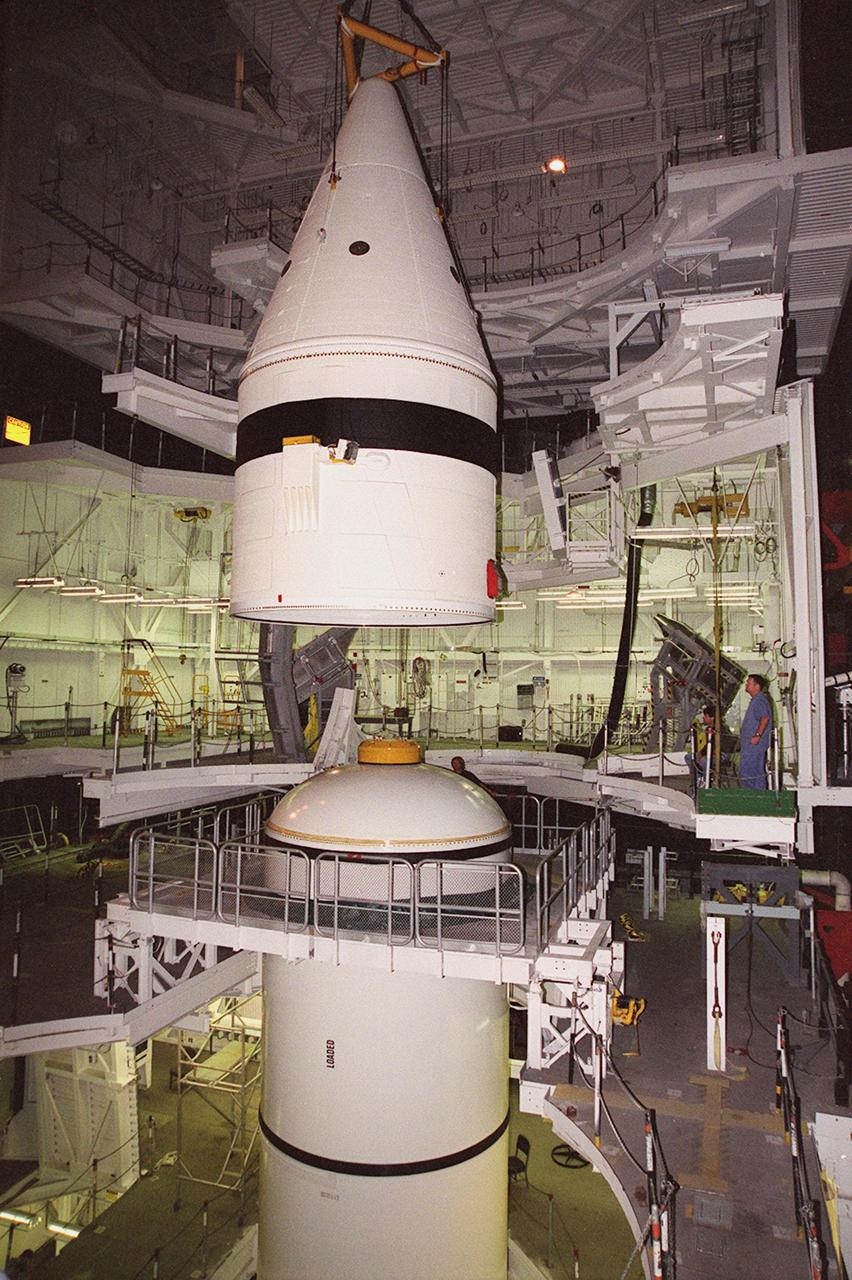
Inside the Vehicle Assembly Building, an overhead crane centers the forward section of a solid rocket booster (SRB) above the rest of the stack it will be mated to. The forward section of each booster, from nose cap to forward skirt contains avionics, a sequencer, forward separation motors, a nose cone separation system, drogue and main parachutes, a recovery beacon, a recovery light, a parachute camera on selected flights and a range safety system. Each SRB weighs approximately 1.3 million pounds at launch. The SRB is part of the stack for Space Shuttle Discovery and the STS-92 mission, scheduled for launch Oct. 5, from Launch Pad 39A, on the fifth flight to the International Space Station
Inside the Vehicle Assembly Building, an overhead crane lowers the forward section of a solid rocket booster (SRB) toward the rest of the stack for mating. The forward section of each booster, from nose cap to forward skirt contains avionics, a sequencer, forward separation motors, a nose cone separation system, drogue and main parachutes, a recovery beacon, a recovery light, a parachute camera on selected flights and a range safety system. Each SRB weighs approximately 1.3 million pounds at launch. The SRB is part of the stack for Space Shuttle Discovery and the STS-92 mission, scheduled for launch Oct. 5, from Launch Pad 39A, on the fifth flight to the International Space Station

Inside the Vehicle Assembly Building, an overhead crane lowers the forward section of a solid rocket booster (SRB) toward the rest of the stack for mating. The forward section of each booster, from nose cap to forward skirt contains avionics, a sequencer, forward separation motors, a nose cone separation system, drogue and main parachutes, a recovery beacon, a recovery light, a parachute camera on selected flights and a range safety system. Each SRB weighs approximately 1.3 million pounds at launch. The SRB is part of the stack for Space Shuttle Discovery and the STS-92 mission, scheduled for launch Oct. 5, from Launch Pad 39A, on the fifth flight to the International Space Station

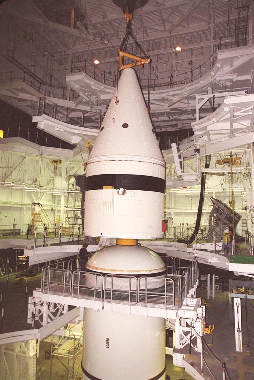
Inside the Vehicle Assembly Building, the forward section of a solid rocket booster (SRB) sits on top of the rest of the stack for mating. The forward section of each booster, from nose cap to forward skirt contains avionics, a sequencer, forward separation motors, a nose cone separation system, drogue and main parachutes, a recovery beacon, a recovery light, a parachute camera on selected flights and a range safety system. Each SRB weighs approximately 1.3 million pounds at launch. The SRB is part of the stack for Space Shuttle Discovery and the STS-92 mission, scheduled for launch Oct. 5, from Launch Pad 39A, on the fifth flight to the International Space Station
Inside the Vehicle Assembly Building, the forward section of a solid rocket booster (SRB) sits on top of the rest of the stack for mating. The forward section of each booster, from nose cap to forward skirt contains avionics, a sequencer, forward separation motors, a nose cone separation system, drogue and main parachutes, a recovery beacon, a recovery light, a parachute camera on selected flights and a range safety system. Each SRB weighs approximately 1.3 million pounds at launch. The SRB is part of the stack for Space Shuttle Discovery and the STS-92 mission, scheduled for launch Oct. 5, from Launch Pad 39A, on the fifth flight to the International Space Station

Inside the Vehicle Assembly Building, the forward section of a solid rocket booster (SRB) is lowered onto the rest of the stack for mating. The forward section of each booster, from nose cap to forward skirt contains avionics, a sequencer, forward separation motors, a nose cone separation system, drogue and main parachutes, a recovery beacon, a recovery light, a parachute camera on selected flights and a range safety system. Each SRB weighs approximately 1.3 million pounds at launch. The SRB is part of the stack for Space Shuttle Discovery and the STS-92 mission, scheduled for launch Oct. 5, from Launch Pad 39A, on the fifth flight to the International Space Station

Inside the Vehicle Assembly Building, an overhead crane centers the forward section of a solid rocket booster (SRB) above the rest of the stack it will be mated to. The forward section of each booster, from nose cap to forward skirt contains avionics, a sequencer, forward separation motors, a nose cone separation system, drogue and main parachutes, a recovery beacon, a recovery light, a parachute camera on selected flights and a range safety system. Each SRB weighs approximately 1.3 million pounds at launch. The SRB is part of the stack for Space Shuttle Discovery and the STS-92 mission, scheduled for launch Oct. 5, from Launch Pad 39A, on the fifth flight to the International Space Station
Inside the Vehicle Assembly Building, the forward section of a solid rocket booster (SRB) is lowered onto the rest of the stack for mating. The forward section of each booster, from nose cap to forward skirt contains avionics, a sequencer, forward separation motors, a nose cone separation system, drogue and main parachutes, a recovery beacon, a recovery light, a parachute camera on selected flights and a range safety system. Each SRB weighs approximately 1.3 million pounds at launch. The SRB is part of the stack for Space Shuttle Discovery and the STS-92 mission, scheduled for launch Oct. 5, from Launch Pad 39A, on the fifth flight to the International Space Station
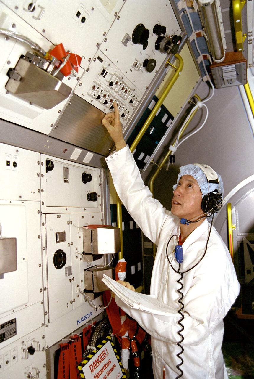
KENNEDY SPACE CENTER, FLA. -- In the Operations and Checkout Building high bay, STS-47 Payload Specialist Dr. Mamoru Mohri is participating in a Mission Sequence Test of the Spacelab-J (SL-J). Also on hand for the test of planned on-orbit activities were Payload Commander Mark Lee and other members of the payload team. Spacelab-J is a joint effort between the Japanese space agency NASDA and NASA, and features an array of 44 life science and materials processing investigations. Dr. Mohri, a payload specialist, will become the first Japanese to fly on the Shuttle.
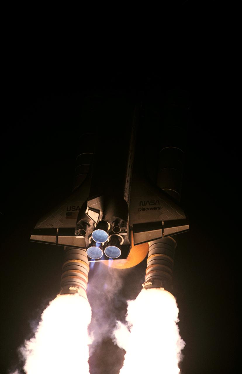
STS063-S-003 (3 Feb. 1995) --- A 35mm camera was used to expose this image of the space shuttle Discovery as it began its race to catch up with the Russia's Mir Space Station. Liftoff from Launch Pad 39B, Kennedy Space Center (KSC) occurred at 12:22:04 (EST), Feb. 3, 1995. Discovery is the first in the current fleet of four space shuttle vehicles to make 20 launches. Onboard for the 67th (STS-63 is out of sequence) shuttle flight are astronauts James D. Wetherbee, commander; Eileen M. Collins, pilot; Bernard A. Harris Jr., payload commander; and mission specialists Janice Voss and C. Michael Foale; along with Russian cosmonaut Vladimir G. Titov. Photo credit: NASA
KENNEDY SPACE CENTER, FLA. -- United Space Alliance technician Dell Chapman applies the glue (red) known as RTV, or room temperature vulcanization, to a strip of gap filler before installation on the orbiter Discovery, which is being processed in Orbiter Processing Facility Bay 3 at NASA’s Kennedy Space Center. This work is being performed due to two gap fillers that were protruding from the underside of Discovery on the first Return to Flight mission, STS-114. New installation procedures have been developed to ensure the gap fillers stay in place and do not pose any hazard during the shuttle's re-entry to the atmosphere. Discovery is the scheduled orbiter for the second space shuttle mission in the return-to-flight sequence.

KENNEDY SPACE CENTER, FLA. -- United Space Alliance technician Dell Chapman applies tape to hold the gap filler in place on the orbiter Discovery while the glue dries. Looking on is quality inspector Travis Schlingman. Discovery is being processed in Orbiter Processing Facility Bay 3 at NASA’s Kennedy Space Center. This work is being performed due to two gap fillers that were protruding from the underside of Discovery on the first Return to Flight mission, STS-114. New installation procedures have been developed to ensure the gap fillers stay in place and do not pose any hazard during the shuttle's re-entry to the atmosphere. Discovery is the scheduled orbiter for the second space shuttle mission in the return-to-flight sequence.
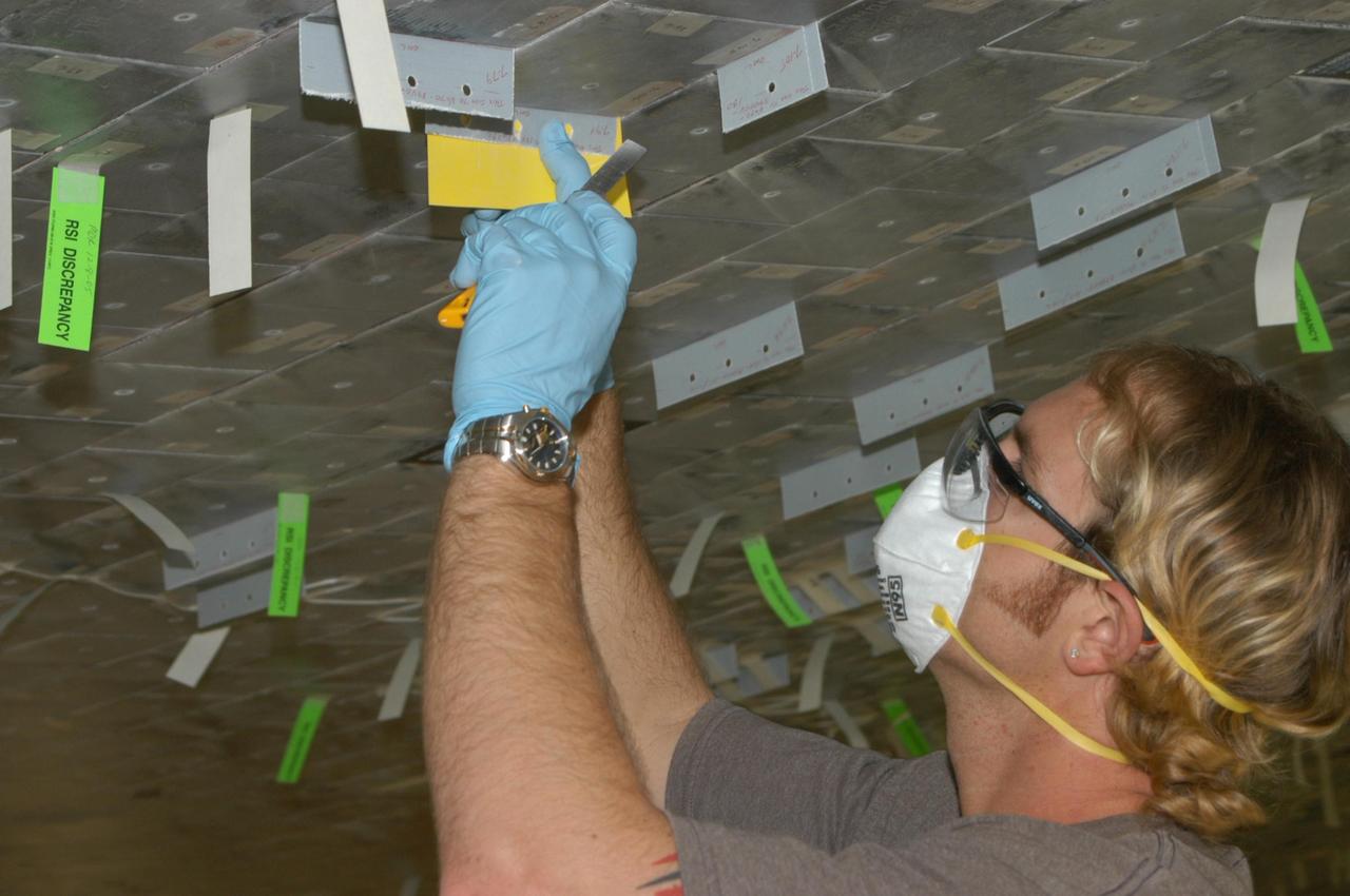
KENNEDY SPACE CENTER, FLA. -- United Space Alliance technician Gene Peavler performs pull tests on newly installed gap fillers. The test now requires three pulls at five pounds each, versus the previous testing of one pull at one-half pound. Discovery is being processed in Orbiter Processing Facility Bay 3 at NASA’s Kennedy Space Center. This work is being performed due to two gap fillers that were protruding from the underside of Discovery on the first Return to Flight mission, STS-114. New installation procedures have been developed to ensure the gap fillers stay in place and do not pose any hazard during the shuttle's re-entry to the atmosphere. Discovery is the scheduled orbiter for the second space shuttle mission in the return-to-flight sequence.

KENNEDY SPACE CENTER, FLA. -- United Space Alliance technician Larry Tanner places Teflon-coated fabric on either side of the gap filler before installation. The fabric ensures the glue remains in place until bonded and then the fabric is later removed. Discovery is being processed in Orbiter Processing Facility Bay 3 at NASA’s Kennedy Space Center. This work is being performed due to two gap fillers that were protruding from the underside of Discovery on the first Return to Flight mission, STS-114. New installation procedures have been developed to ensure the gap fillers stay in place and do not pose any hazard during the shuttle's re-entry to the atmosphere. Discovery is the scheduled orbiter for the second space shuttle mission in the return-to-flight sequence.
KENNEDY SPACE CENTER, FLA. -- United Space Alliance technician Larry Tanner punches three holes in the gap filler to be installed on Discovery. The holes are used for the string pull test done after installation to ensure the gap filler is bonded properly. Discovery is being processed in Orbiter Processing Facility Bay 3 at NASA’s Kennedy Space Center. This work is being performed due to two gap fillers that were protruding from the underside of Discovery on the first Return to Flight mission, STS-114. New installation procedures have been developed to ensure the gap fillers stay in place and do not pose any hazard during the shuttle's re-entry to the atmosphere. Discovery is the scheduled orbiter for the second space shuttle mission in the return-to-flight sequence.
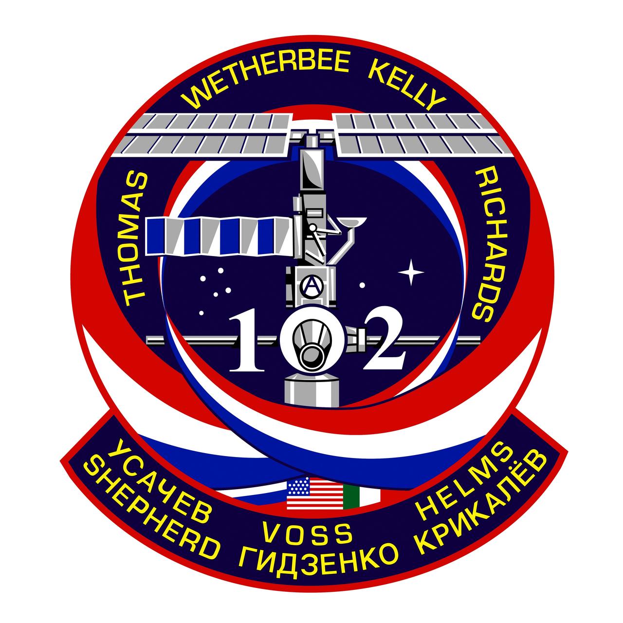
STS102-S-001 (January 2001) --- The central image on the STS-102 crew patch depicts the International Space Station (ISS) in the build configuration that it will have at the time of the arrival and docking of Discovery during the STS-102 mission, the first crew exchange flight to the space station. The station is shown along the direction of the flight as will be seen by the shuttle crew during their final approach and docking, the so-called V-bar approach. The names of the shuttle crew members are depicted in gold around the top of the patch, and surnames of the Expedition crew members being exchanged are shown in the lower banner. The three ribbons swirling up to and around the station signify the rotation of these ISS crew members. The number two is for the Expedition Two crew who fly up to the station, and the number one is for the Expedition One crew who then return down to Earth. In conjunction with the face of the Lab module of the station, these Expedition numbers create the shuttle mission number 102. Shown mated below the ISS is the Italian-built Multi-Purpose Logistics Module, Leonardo, that will fly for the first time on this flight, and which will be attached to the station by the shuttle crew during the docked phase of the mission. The flags of the countries that are the major contributors to this effort, the United States, Russia, and Italy are also shown in the lower part of the patch. The build-sequence number of this flight in the overall station assembly sequence, 5A.1, is captured by the constellations in the background. The NASA insignia design for space shuttle flights is reserved for use by the astronauts and for other official use as the NASA Administrator may authorize. Public availability has been approved only in the forms of illustrations by the various news media. When and if there is any change in this policy, which is not anticipated, the change will be publicly announced. Photo credit: NASA

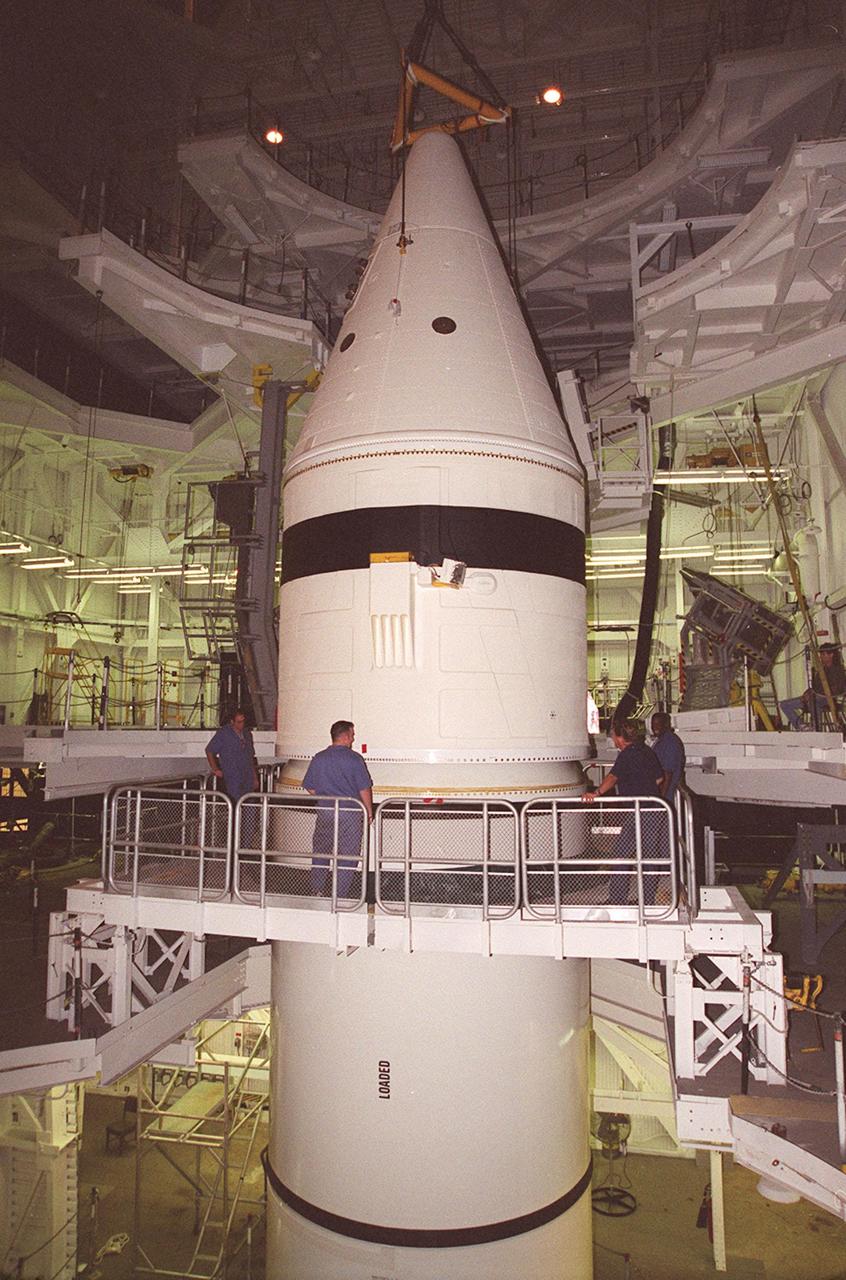
Workers in the Vehicle Assembly Building check the connections on the forward section of a solid rocket booster (SRB) being mated to the rest of the stack below it. The forward section of each booster, from nose cap to forward skirt contains avionics, a sequencer, forward separation motors, a nose cone separation system, drogue and main parachutes, a recovery beacon, a recovery light, a parachute camera on selected flights and a range safety system. Each SRB weighs approximately 1.3 million pounds at launch. The SRB is part of the stack for Space Shuttle Discovery and the STS-92 mission, scheduled for launch Oct. 5, from Launch Pad 39A, on the fifth flight to the International Space Station. Payloads on the mission include the Z-1 truss and Pressurized Mating Adapter-3, components of the Space Station
Workers in the Vehicle Assembly Building check the connections on the forward section of a solid rocket booster (SRB) being mated to the rest of the stack below it. The forward section of each booster, from nose cap to forward skirt contains avionics, a sequencer, forward separation motors, a nose cone separation system, drogue and main parachutes, a recovery beacon, a recovery light, a parachute camera on selected flights and a range safety system. Each SRB weighs approximately 1.3 million pounds at launch. The SRB is part of the stack for Space Shuttle Discovery and the STS-92 mission, scheduled for launch Oct. 5, from Launch Pad 39A, on the fifth flight to the International Space Station. Payloads on the mission include the Z-1 truss and Pressurized Mating Adapter-3, components of the Space Station
S94-30393 (23 Nov 1993) --- In the south level IV stand of the Operations and Checkout Building low bay, the Space Radar Laboratory -1 (SRL-1) antenna is being placed atop a pallet which holds the antenna electronics. SRL-1 is scheduled to fly on Space Shuttle mission STS-59 next year. It is comprised of two different imaging radars, the Spaceborne Imaging Radar-C (SIR-C) and the X-band Synthetic Aperture Radar (X-SAR). These radars are the most advanced of their kind to fly in space to date, and will allow scientists to make highly detailed studies of the Earth's surface on a global scale. An Interface Verification Test of the antenna and a Mission Sequence Test will be performed on the fully assembled SRL-1 later this month.

Workers in the Vehicle Assembly Building check the connections on the forward section of a solid rocket booster (SRB) being mated to the rest of the stack below it. The forward section of each booster, from nose cap to forward skirt contains avionics, a sequencer, forward separation motors, a nose cone separation system, drogue and main parachutes, a recovery beacon, a recovery light, a parachute camera on selected flights and a range safety system. Each SRB weighs approximately 1.3 million pounds at launch. The SRB is part of the stack for Space Shuttle Discovery and the STS-92 mission, scheduled for launch Oct. 5, from Launch Pad 39A, on the fifth flight to the International Space Station. Payloads on the mission include the Z-1 truss and Pressurized Mating Adapter-3, components of the Space Station
Workers in the Vehicle Assembly Building check the connections on the forward section of a solid rocket booster (SRB) being mated to the rest of the stack below it. The forward section of each booster, from nose cap to forward skirt contains avionics, a sequencer, forward separation motors, a nose cone separation system, drogue and main parachutes, a recovery beacon, a recovery light, a parachute camera on selected flights and a range safety system. Each SRB weighs approximately 1.3 million pounds at launch. The SRB is part of the stack for Space Shuttle Discovery and the STS-92 mission, scheduled for launch Oct. 5, from Launch Pad 39A, on the fifth flight to the International Space Station. Payloads on the mission include the Z-1 truss and Pressurized Mating Adapter-3, components of the Space Station
KENNEDY SPACE CENTER, FLA. -- The Z1 Integrated Truss Segment (ITS), a major element of the STS-92 mission scheduled for launch aboard Space Shuttle Atlantis in January 1999, is moved to its workstand for processing in KSC's Space Station Processing Facility (SSPF). The Z-1 truss supports the staged buildup of International Space Station (ISS) on this third scheduled flight for ISS. The Z1 truss allows the temporary installation of the U.S. power module to Node 1. Early in the assembly sequence, the purpose of Z1 is to provide a mounting location for Ku-band and S-band telemetry and extravehicular activity (EVA) equipment. It also provides common berthing mechanism hardcover stowage. In addition, it will assist with the execution of nonpropulsive attitude control. The truss arrived at KSC on Feb. 17 for preflight processing in the SSPF
KENNEDY SPACE CENTER, FLA. -- The Z1 Integrated Truss Segment (ITS), a major element of the STS-92 mission scheduled for launch aboard Space Shuttle Atlantis in January 1999, is lowered into its workstand for processing in KSC's Space Station Processing Facility (SSPF). The Z-1 truss supports the staged buildup of International Space Station (ISS) on this third scheduled flight for ISS. The Z1 truss allows the temporary installation of the U.S. power module to Node 1. Early in the assembly sequence, the purpose of Z1 is to provide a mounting location for Ku-band and S-band telemetry and extravehicular activity (EVA) equipment. It also provides common berthing mechanism hardcover stowage. In addition, it will assist with the execution of nonpropulsive attitude control. The truss arrived at KSC on Feb. 17 for preflight processing in the SSPF

KENNEDY SPACE CENTER, FLA. -- The Z1 Integrated Truss Segment (ITS), a major element of the STS-92 mission scheduled for launch aboard Space Shuttle Atlantis in January 1999, is moved toward its workstand for processing in KSC's Space Station Processing Facility (SSPF). The Z-1 truss supports the staged buildup of International Space Station (ISS) on this third scheduled flight for ISS. The Z1 truss allows the temporary installation of the U.S. power module to Node 1. Early in the assembly sequence, the purpose of Z1 is to provide a mounting location for Ku-band and S-band telemetry and extravehicular activity (EVA) equipment. It also provides common berthing mechanism hardcover stowage. In addition, it will assist with the execution of nonpropulsive attitude control. The truss arrived at KSC on Feb. 17 for preflight processing in the SSPF
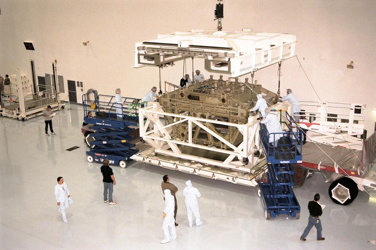
KENNEDY SPACE CENTER, FLA. -- The Z1 Integrated Truss Segment (ITS), a major element of the STS-92 mission scheduled for launch aboard Space Shuttle Atlantis in January 1999, is lowered into its workstand for processing in KSC's Space Station Processing Facility (SSPF). The Z-1 truss supports the staged buildup of International Space Station (ISS) on this third scheduled flight for ISS. The Z1 truss allows the temporary installation of the U.S. power module to Node 1. Early in the assembly sequence, the purpose of Z1 is to provide a mounting location for Ku-band and S-band telemetry and extravehicular activity (EVA) equipment. It also provides common berthing mechanism hardcover stowage. In addition, it will assist with the execution of nonpropulsive attitude control. The truss arrived at KSC on Feb. 17 for preflight processing in the SSPF
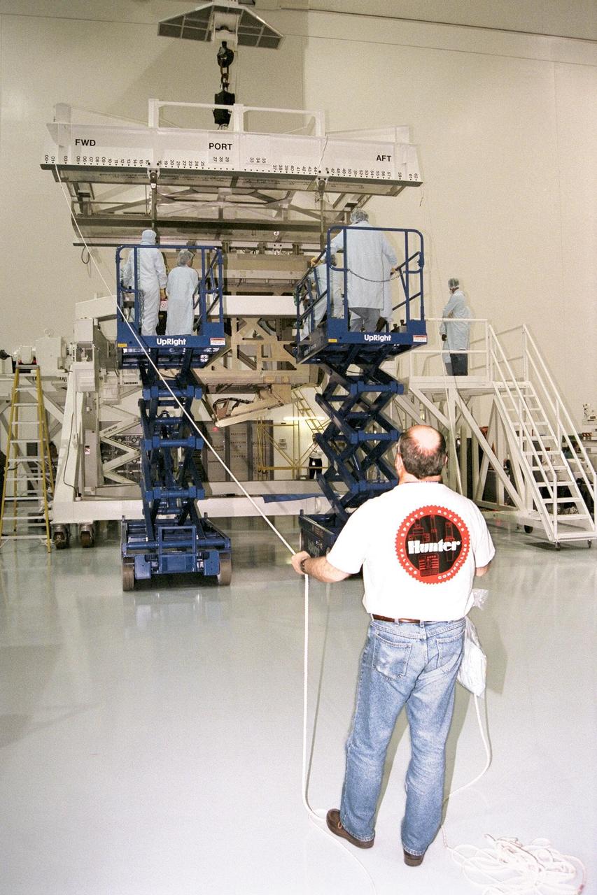
KENNEDY SPACE CENTER, FLA. -- The Z1 Integrated Truss Segment (ITS), a major element of the STS-92 mission scheduled for launch aboard Space Shuttle Atlantis in January 1999, is lowered into its workstand for processing in KSC's Space Station Processing Facility (SSPF). The Z-1 truss supports the staged buildup of International Space Station (ISS) on this third scheduled flight for ISS. The Z1 truss allows the temporary installation of the U.S. power module to Node 1. Early in the assembly sequence, the purpose of Z1 is to provide a mounting location for Ku-band and S-band telemetry and extravehicular activity (EVA) equipment. It also provides common berthing mechanism hardcover stowage. In addition, it will assist with the execution of nonpropulsive attitude control. The truss arrived at KSC on Feb. 17 for preflight processing in the SSPF

KENNEDY SPACE CENTER, FLA. -- The Z1 Integrated Truss Segment (ITS), a major element of the STS-92 mission scheduled for launch aboard Space Shuttle Atlantis in January 1999, is lowered into its workstand for processing in KSC's Space Station Processing Facility (SSPF). The Z-1 truss supports the staged buildup of International Space Station (ISS) on this third scheduled flight for ISS. The Z1 truss allows the temporary installation of the U.S. power module to Node 1. Early in the assembly sequence, the purpose of Z1 is to provide a mounting location for Ku-band and S-band telemetry and extravehicular activity (EVA) equipment. It also provides common berthing mechanism hardcover stowage. In addition, it will assist with the execution of nonpropulsive attitude control. The truss arrived at KSC on Feb. 17 for preflight processing in the SSPF
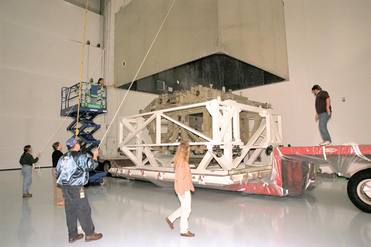
Workers in KSC's Space Station Processing Facility (SSPF) assist in removing the protective casing from the Z1 Integrated Truss Segment (ITS), a major element of the STS-92 mission scheduled for launch aboard Space Shuttle Atlantis in January 1999. The Z-1 truss supports the staged buildup of International Space Station (ISS) on this third scheduled flight for ISS. The Z1 truss allows the temporary installation of the U.S. power module to Node 1. Early in the assembly sequence, the purpose of Z1 is to provide a mounting location for Ku-band and S-band telemetry and extravehicular activity (EVA) equipment. It also provides common berthing mechanism hardcover stowage. In addition, it will assist with the execution of nonpropulsive attitude control. The truss arrived at KSC on Feb. 17 for preflight processing in the SSPF
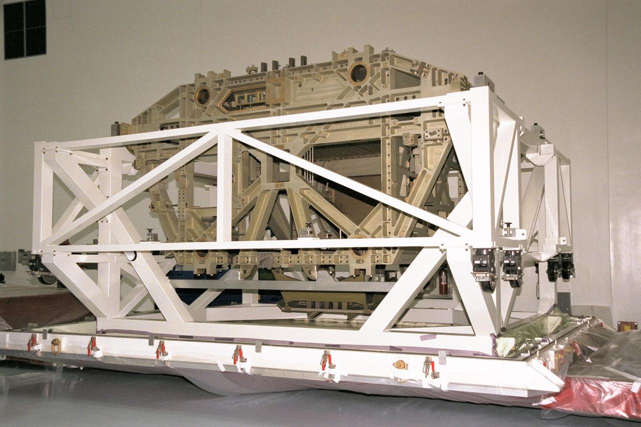
The Z1 Integrated Truss Segment (ITS), a major element of the STS-92 mission scheduled for launch aboard Space Shuttle Atlantis in January 1999, awaits processing in KSC's Space Station Processing Facility (SSPF). The Z-1 truss supports the staged buildup of International Space Station (ISS) on this third scheduled flight for ISS. The Z1 truss allows the temporary installation of the U.S. power module to Node 1. Early in the assembly sequence, the purpose of Z1 is to provide a mounting location for Ku-band and S-band telemetry and extravehicular activity (EVA) equipment. It also provides common berthing mechanism hardcover stowage. In addition, it will assist with the execution of nonpropulsive attitude control. The truss arrived at KSC on Feb. 17 for preflight processing in the SSPF
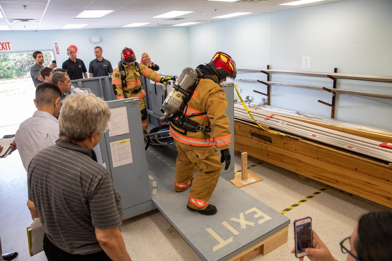
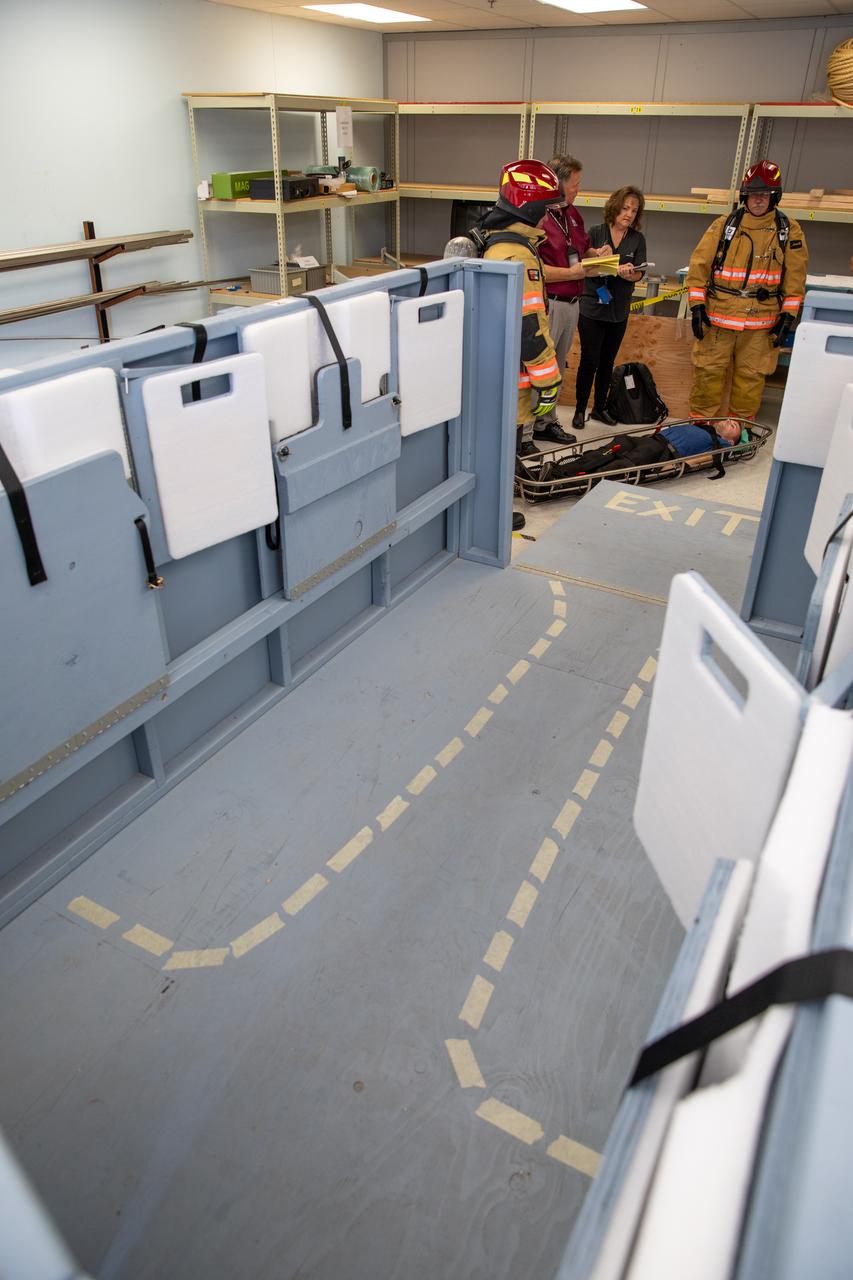
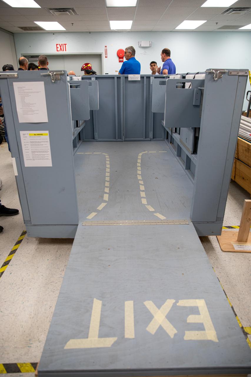
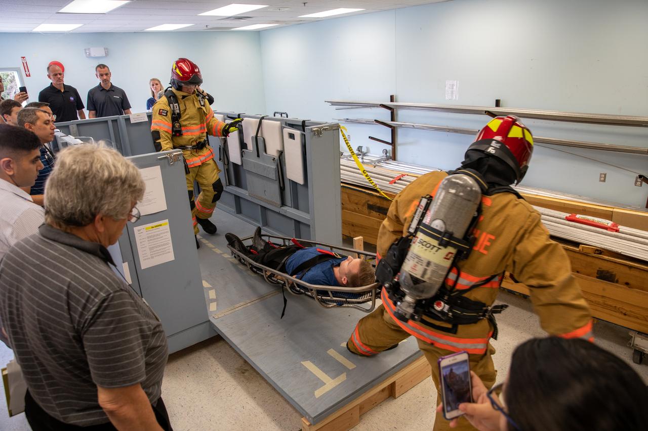
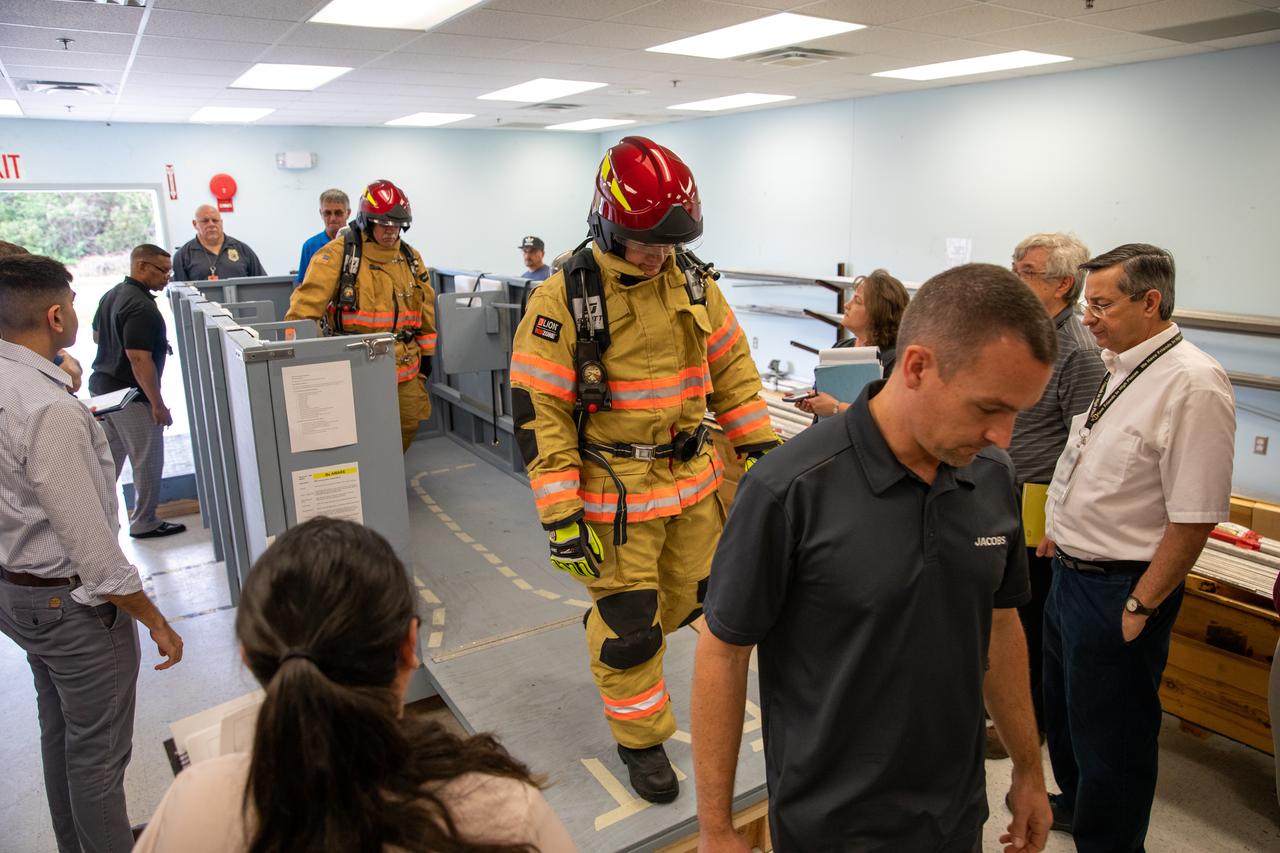
Members of NASA Kennedy Space Center’s Fire Rescue team conduct a series of trial scenarios in a mock-up of a launch pad escape basket on Feb. 19, 2020. Kennedy’s prime contractor Reynolds, Smith and Hill presented the mock-up to NASA, Kennedy Fire Rescue personnel and other stakeholders at the Florida spaceport. The basket would be utilized at Launch Pad 39B in the unlikely event of an emergency at the pad requiring evacuation during crewed missions under the Artemis Program. The actual egress basket will be designed larger than ones used during the shuttle era in order to accommodate fire rescue crew, astronauts and closeout crew. During the presentation, items such as basket release location, seat depth to accommodate firefighters in full gear, sequence of loading and more were addressed. Engineers will take what they learned during this presentation and discussion to advance the design of the pad egress system.
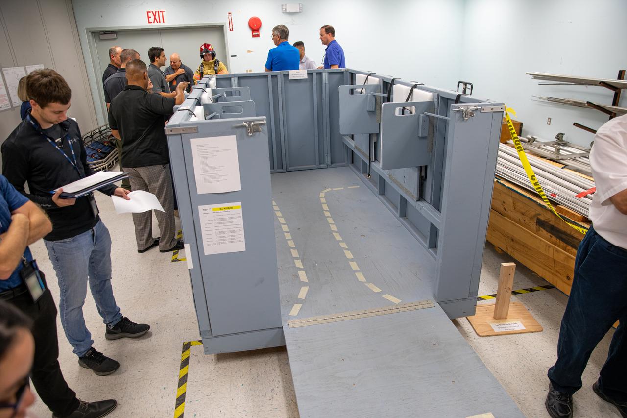
NASA Kennedy Space Center’s prime contractor Reynolds, Smith and Hill presents a mock-up of a launch pad escape basket to NASA, Kennedy Fire Rescue personnel and other stakeholders on Feb. 19, 2020. The basket would be utilized at the Florida spaceport’s Launch Pad 39B in the unlikely event of an emergency at the pad requiring evacuation during crewed missions under the Artemis Program. The actual egress basket will be designed larger than ones used during the shuttle era in order to accommodate fire rescue crew, astronauts and closeout crew. During the presentation, a fire rescue team walked through a series of trial scenarios and addressed items such as basket release location, seat depth to accommodate firefighters in full gear, sequence of loading and more.
NASA Kennedy Space Center’s prime contractor Reynolds, Smith and Hill presents a mock-up of a launch pad escape basket to NASA, Kennedy Fire Rescue personnel and other stakeholders on Feb. 19, 2020. The basket would be utilized at the Florida spaceport’s Launch Pad 39B in the unlikely event of an emergency at the pad requiring evacuation during crewed missions under the Artemis Program. The actual egress basket will be designed larger than ones used during the shuttle era in order to accommodate fire rescue crew, astronauts and closeout crew. During the presentation, a fire rescue team walked through a series of trial scenarios and addressed items such as basket release location, seat depth to accommodate firefighters in full gear, sequence of loading and more.
NASA Kennedy Space Center’s prime contractor Reynolds, Smith and Hill presents a mock-up of a launch pad escape basket to NASA, Kennedy Fire Rescue personnel and other stakeholders on Feb. 19, 2020. The basket would be utilized at the Florida spaceport’s Launch Pad 39B in the unlikely event of an emergency at the pad requiring evacuation during crewed missions under the Artemis Program. The actual egress basket will be designed larger than ones used during the shuttle era in order to accommodate fire rescue crew, astronauts and closeout crew. During the presentation, a fire rescue team walked through a series of trial scenarios and addressed items such as basket release location, seat depth to accommodate firefighters in full gear, sequence of loading and more.
Members of NASA Kennedy Space Center’s Fire Rescue team conduct a series of trial scenarios in a mock-up of a launch pad escape basket on Feb. 19, 2020. Kennedy’s prime contractor Reynolds, Smith and Hill presented the mock-up to NASA, Kennedy Fire Rescue personnel and other stakeholders at the Florida spaceport. The basket would be utilized at Launch Pad 39B in the unlikely event of an emergency at the pad requiring evacuation during crewed missions under the Artemis Program. The actual egress basket will be designed larger than ones used during the shuttle era in order to accommodate fire rescue crew, astronauts and closeout crew. During the presentation, items such as basket release location, seat depth to accommodate firefighters in full gear, sequence of loading and more were addressed. Engineers will take what they learned during this presentation and discussion to advance the design of the pad egress system.
Members of NASA Kennedy Space Center’s Fire Rescue team walk through a mock-up of a launch pad escape basket on Feb. 19, 2020. Kennedy’s prime contractor Reynolds, Smith and Hill presented the mock-up to NASA, fire rescue personnel and other stakeholders at the Florida spaceport. The basket would be utilized at Launch Pad 39B in the unlikely event of an emergency at the pad requiring evacuation during crewed missions under the Artemis Program. The actual egress basket will be designed larger than ones used during the shuttle era in order to accommodate fire rescue crew, astronauts and closeout crew. During the presentation, a fire rescue team conducted a series of trial scenarios and addressed items such as basket release location, seat depth to accommodate firefighters in full gear, sequence of loading and more.
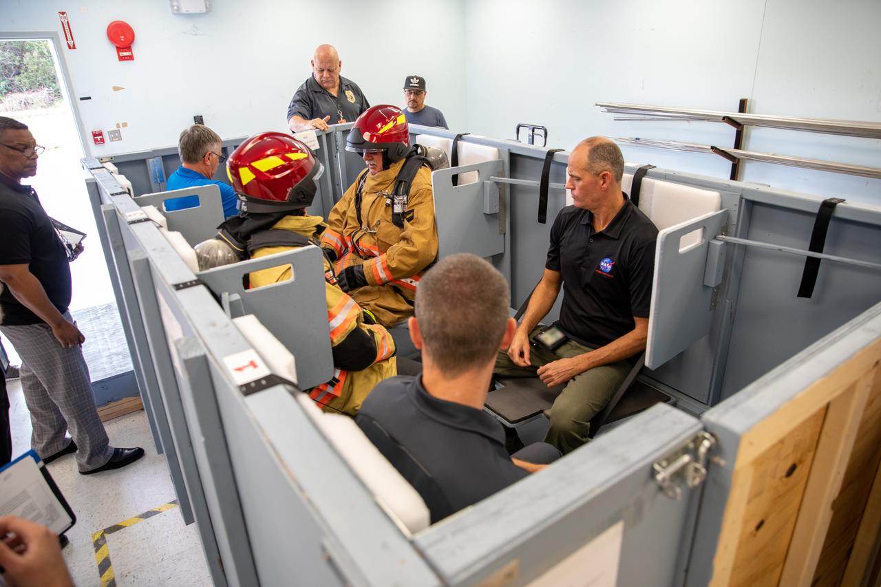
On Feb. 19, 2020, at NASA’s Kennedy Space Center in Florida, prime contractor Reynolds, Smith and Hill presents a mock-up of a launch pad escape basket to NASA, Kennedy Fire Rescue personnel and other stakeholders. The basket would be utilized at Launch Pad 39B in the unlikely event of an emergency at the pad requiring evacuation during crewed missions under the Artemis Program. The actual egress basket will be designed larger than ones used during the shuttle era in order to accommodate fire rescue crew, astronauts and closeout crew. During the presentation, a fire rescue team walked through a series of trial scenarios and addressed items such as basket release location, seat depth to accommodate firefighters in full gear, sequence of loading and more.
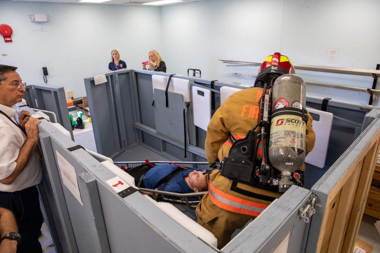
Members of NASA Kennedy Space Center’s Fire Rescue team participate in a series of trial scenarios in a mock-up of a launch pad escape basket on Feb. 19, 2020. Kennedy’s prime contractor Reynolds, Smith and Hill presented the mock-up to NASA, Kennedy Fire Rescue personnel and other stakeholders at the Florida spaceport. The basket would be utilized at Launch Pad 39B in the unlikely event of an emergency at the pad requiring evacuation during crewed missions under the Artemis Program. The actual egress basket will be designed larger than ones used during the shuttle era in order to accommodate fire rescue crew, astronauts and closeout crew. During the presentation, items such as basket release location, seat depth to accommodate firefighters in full gear, sequence of loading and more were addressed. Engineers will take what they learned during this presentation and discussion to advance the design of the pad egress system.
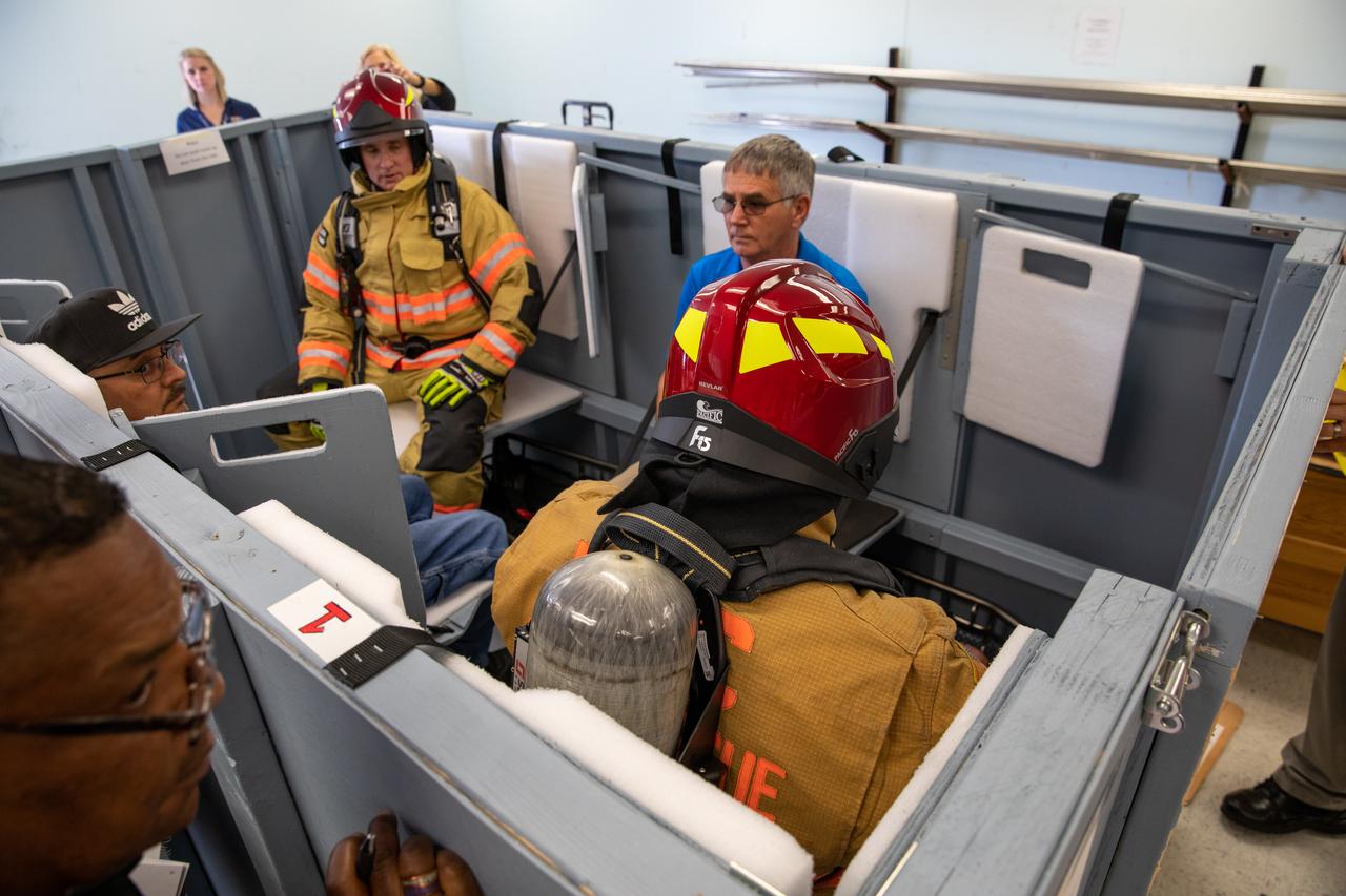
Members of NASA Kennedy Space Center’s Fire Rescue team conduct a series of trial scenarios in a mock-up of a launch pad escape basket on Feb. 19, 2020. Kennedy’s prime contractor Reynolds, Smith and Hill presented the mock-up to NASA, Kennedy Fire Rescue personnel and other stakeholders at the Florida spaceport. The basket would be utilized at Launch Pad 39B in the unlikely event of an emergency at the pad requiring evacuation during crewed missions under the Artemis Program. The actual egress basket will be designed larger than ones used during the shuttle era in order to accommodate fire rescue crew, astronauts and closeout crew. During the presentation, items such as basket release location, seat depth to accommodate firefighters in full gear, sequence of loading and more were addressed. Engineers will take what they learned during this presentation and discussion to advance the design of the pad egress system.
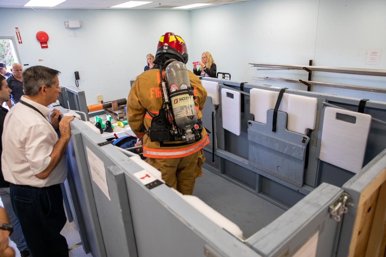
Members of NASA Kennedy Space Center’s Fire Rescue team conduct a series of trial scenarios in a mock-up of a launch pad escape basket on Feb. 19, 2020. Kennedy’s prime contractor Reynolds, Smith and Hill presented the mock-up to NASA, Kennedy Fire Rescue personnel and other stakeholders at the Florida spaceport. The basket would be utilized at Launch Pad 39B in the unlikely event of an emergency at the pad requiring evacuation during crewed missions under the Artemis Program. The actual egress basket will be designed larger than ones used during the shuttle era in order to accommodate fire rescue crew, astronauts and closeout crew. During the presentation, items such as basket release location, seat depth to accommodate firefighters in full gear, sequence of loading and more were addressed. Engineers will take what they learned during this presentation and discussion to advance the design of the pad egress system.
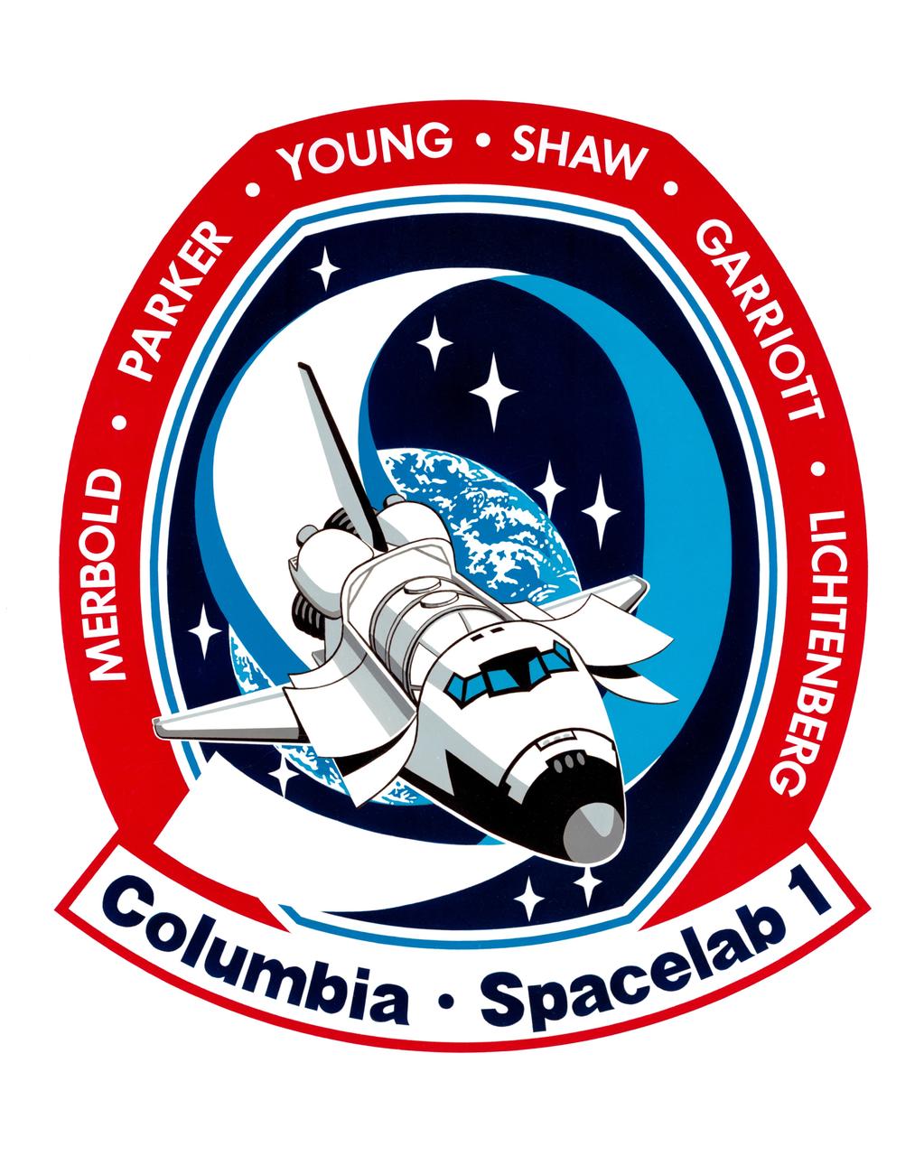
S83-32900 (25 May 1983) --- This is the official insignia for STS-9, the major payload of which is Spacelab-1, depicted in the cargo bay of the space shuttle Columbia. The nine stars and the path of the orbiter tell the flight's numerical designation in the Space Transportation System's mission sequence. Astronaut John W. Young is crew commander; Brewster H. Shaw Jr., pilot. NASA astronauts Owen K. Garriott and Robert A.R. Parker are mission specialists. Byron K. Lichtenberg of the Massachusetts Institute of Technology and Ulf Merbold of the Republic of West Germany are the Spacelab-1 payload specialists. Launch has been set for late 1983. Merbold is a physicist representing the European Space Agency (ESA). The NASA insignia design for space shuttle flights is reserved for use by the astronauts and for other official use as the NASA Administrator may authorize. Public availability has been approved only in the forms of illustrations by the various news media. When and if there is any change in this policy, which is not anticipated, the change will be publicly announced. Photo credit: NASA
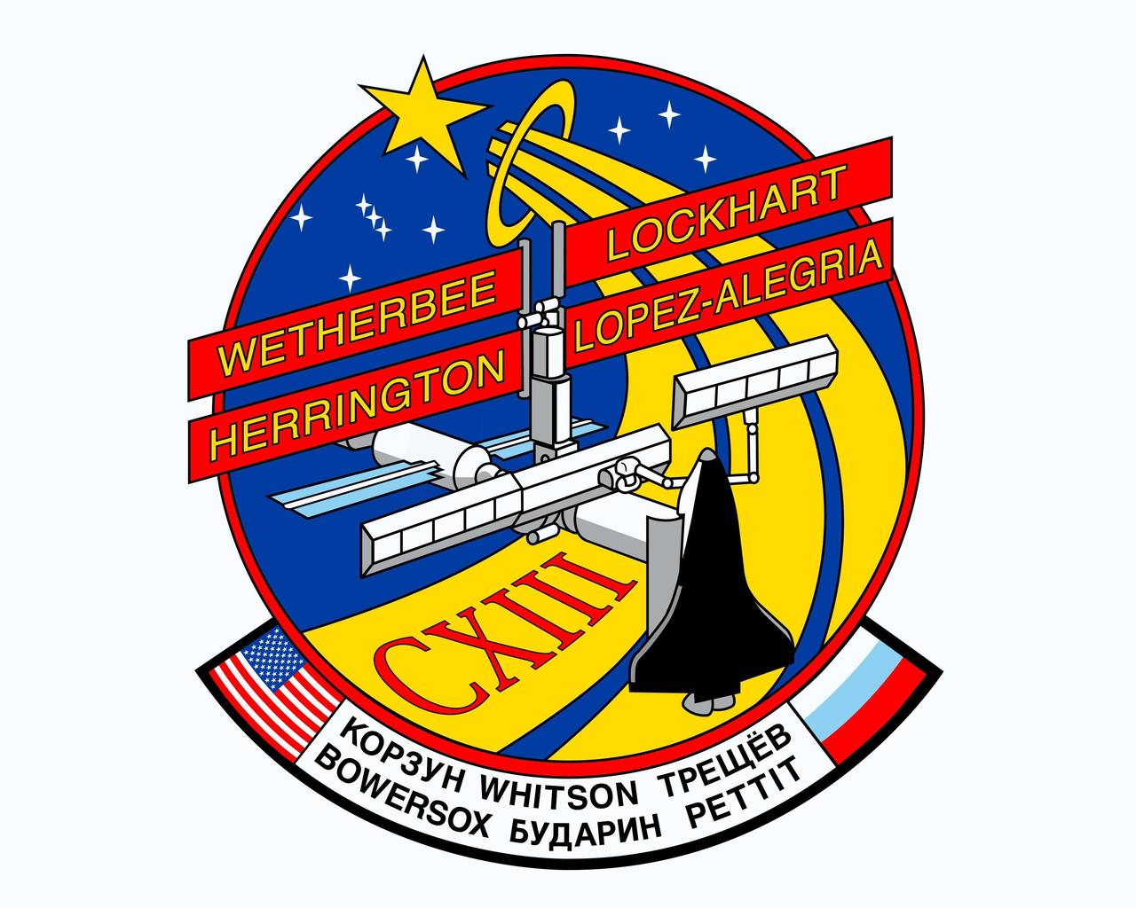
JOHNSON SPACE CENTER, HOUSTON, TEXAS - (STS113-S-001 September 2002) -- This is the crew patch for the STS-113 mission, which will be the 11th American (11A) assembly flight to the International Space Station (ISS). The primary mission will be to take the Expedition Six crew to the ISS and return the Expedition Five crew to Earth. STS-113 will be the first flight in the assembly sequence to install a major component in addition to performing a crew exchange. The Port 1 Integrated Truss Assembly (P1) will be the first truss segment on the left side of the ISS. P1 will provide an additinal three External Thermal Control System radiators, adding to the three radiators on the Starboard 1 (S1) Integrated Truss Assembly. The installation and outfitting of P1 will require three extravehicular activities (spacewalks) as well as coordination between the Shuttle Robotic Manipulator System and the Space Station Robotic Manipulator System. The patch depicts the Space Shuttle Endeavour docked to the ISS during the installation of the P1 truss withthe gold astronaut symbol in the background. The seven stars at the top left center of the patch are the seven brightest stars in the constellation Orion. They represent the combined seven crew members (four Shuttle and three Expedition Six). The three stars to the right of the astronaut symbol represent the returning Expedition Five crew members. The Roman Numeral CXIII represents the mission number 113. The NASA insignia design for Shuttle space flights is reserved for use by the astronauts and other official use as the NASA Administrator may authorize. Public availability has been approved only in the form of illustrations by the various news media. When and if there is any change in this policy, which is not anticipated, such will be publicly announced.

STS113-S-001 (September 2002) --- This is the crew patch for the STS-113 mission, which will be the eleventh American (11A) assembly flight to the International Space Station (ISS). The primary mission will be to take the Expedition Six crew to the ISS and return the Expedition Five crew to Earth. STS-113 will be the first flight in the assembly sequence to install a major component in addition to performing a crew exchange. The Port 1 Integrated Truss Assembly (P1) will be the first truss segment on the left side of the ISS. P1 will provide an additional three External Thermal Control System radiators, adding to the three radiators on the Starboard 1 (S1) Integrated Truss Assembly. The installation and outfitting of P1 will require three extravehicular activities (spacewalks) as well as coordination between the Shuttle Robotic Manipulator System and the Space Station Robotic Manipulator System. The patch depicts the space shuttle Endeavour docked to the ISS during the installation of the P1 truss with the gold astronaut symbol in the background. The seven stars at the top left center of the patch are the seven brightest stars in the constellation Orion. They represent the combined seven crew members (four shuttle and three Expedition Six). The three stars to the right of the astronaut symbol represent the returning Expedition Five crew members. The Roman Numeral CXIII represents the mission number 113. The NASA insignia design for space shuttle flights is reserved for use by the astronauts and for other official use as the NASA Administrator may authorize. Public availability has been approved only in the forms of illustrations by the various news media. When and if there is any change in this policy, which is not anticipated, the change will be publicly announced. Photo credit: NASA
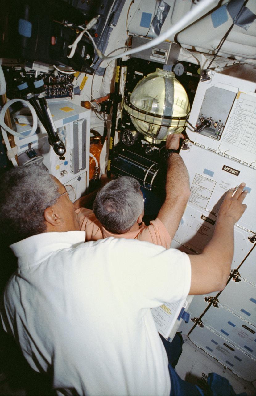
STS053-04-018 (2-9 Dec 1992) --- Astronauts Guion S. Bluford (left) and Michael R. U. (Rich) Clifford monitor the Fluid Acquisition and Resupply Equipment (FARE) onboard the Space Shuttle Discovery. Clearly visible in the mid-deck FARE setup is one of two 12.5-inch spherical tanks made of transparent acrylic, one to supply and one to receive fluids. The purpose of FARE is to investigate the dynamics of fluid transfer in microgravity and develop methods for transferring vapor-free propellants and other liquids that must be replenished in long-term space systems like satellites, Extended-Duration Orbiters (EDO), and Space Station Freedom. Eight times over an eight-hour test period, the mission specialists conducted the FARE experiment. A sequence of manual valve operations caused pressurized air from the bottles to force fluids from the supply tank to the receiver tank and back again to the supply tank. Baffles in the receiver tank controlled fluid motion during transfer, a fine-mesh screen filtered vapor from the fluid, and the overboard vent removed vapor from the receiver tank as the liquid rose. FARE is managed by NASA's Marshall Space Flight Center (MSFC) in Alabama. The basic equipment was developed by Martin Marietta for the Storable Fluid Management Demonstration. Susan L. Driscoll is the principal investigator.
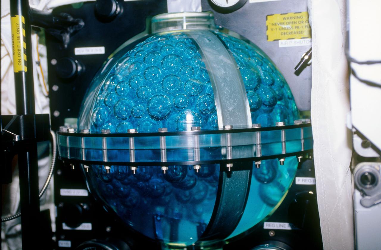
STS053-09-019 (2 - 9 Dec 1992) --- A medium close-up view of part of the Fluid Acquisition and Resupply Equipment (FARE) onboard the Space Shuttle Discovery. Featured in the mid-deck FARE setup is fluid activity in one of two 12.5-inch spherical tanks made of transparent acrylic. Pictured is the receiver tank. The other tank, out of frame below, is for supplying fluids. The purpose of FARE is to investigate the dynamics of fluid transfer in microgravity and develop methods for transferring vapor-free propellants and other liquids that must be replenished in long-term space systems like satellites, Extended-Duration Orbiters (EDO), and Space Station Freedom. Eight times over an eight-hour test period, the mission specialists conducted the FARE experiment. A sequence of manual valve operations caused pressurized air from the bottles to force fluids from the supply tank to the receiver tank and back again to the supply tank. Baffles in the receiver tank controlled fluid motion during transfer, a fine-mesh screen filtered vapor from the fluid, and the overboard vent removed vapor from the receiver tank as the liquid rose. FARE is managed by NASA's Marshall Space Flight Center (MSFC) in Alabama. The basic equipment was developed by Martin Marietta for the Storable Fluid Management Demonstration. Susan L. Driscoll is the principal investigator.
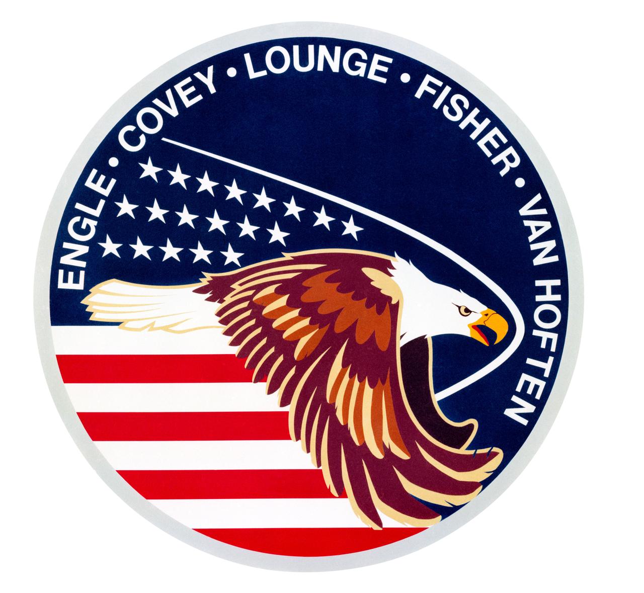
S85-25870 (August 1985) --- The crew emblem for STS-51I is based on a strong patriotic theme with the basic colors of red, white and blue suggesting the American flag and a dominant American bald eagle in aggressive flight. The 19 stars signify the numerical sequence of the flight. The shock wave represents that formed by the orbiter during the entry phase of the flight. Surnames of crew members surround the top part of the circular design. The five-member crew composed of astronauts Joe H. Engle, commander; Richard O. Covey, pilot; John Michael (Mike) Lounge, William F. Fisher and James D. van Hoften, all mission specialists. The NASA insignia design for space shuttle flights is reserved for use by the astronauts and for other official use as the NASA Administrator may authorize. Public availability has been approved only in the forms of illustrations by the various news media. When and if there is any change in this policy, which is not anticipated, the change will be publicly announced. Photo credit: NASA