
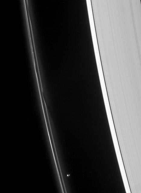
Speeding Away from Tethys
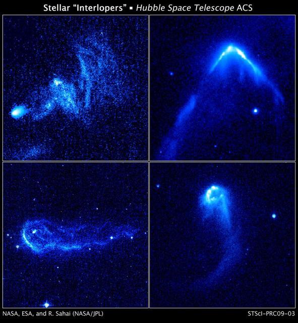
Stellar Interlopers Caught Speeding Through Space
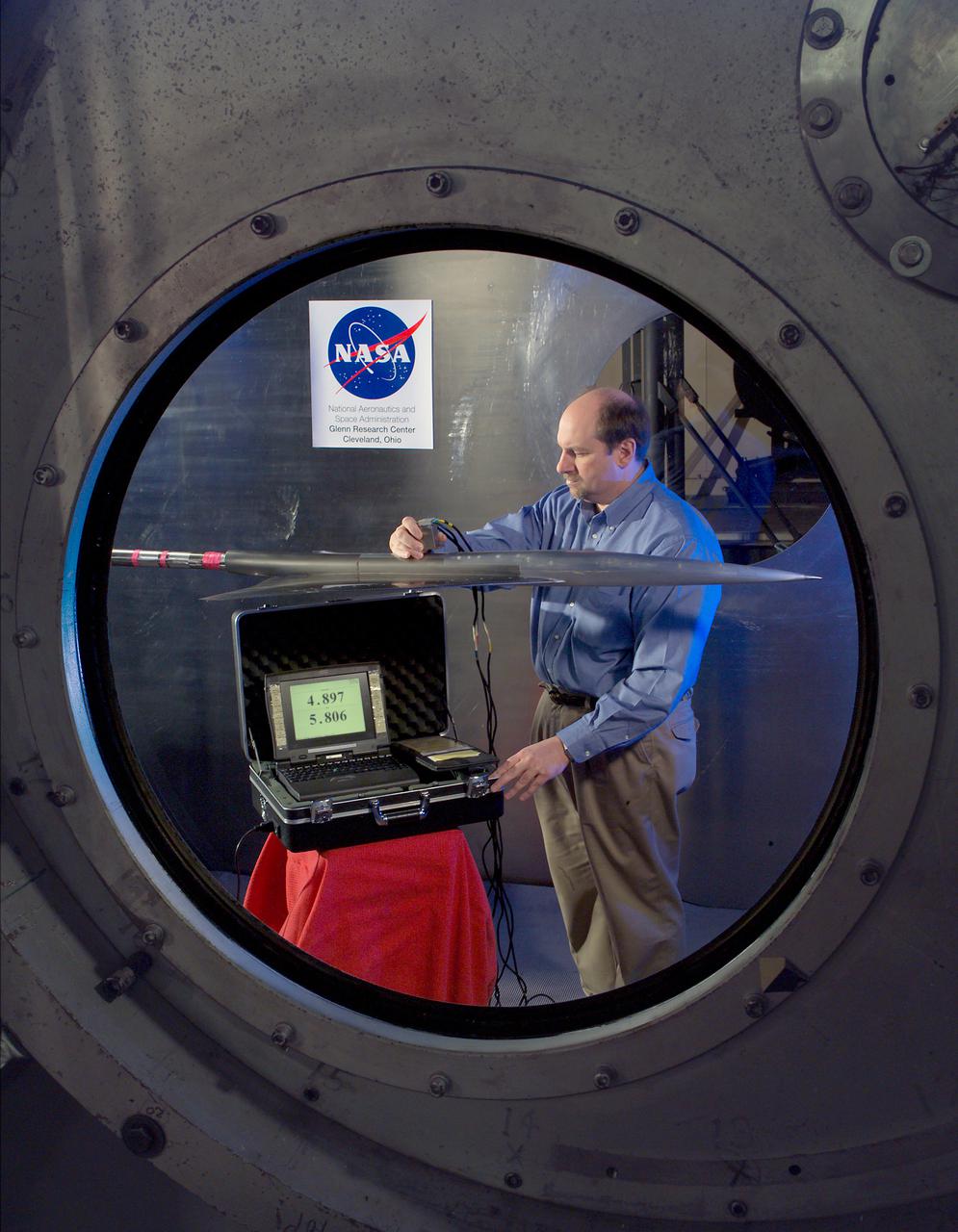
Research Model in the 7x10 High Speed Tunnel Building 1212B 300 mph tunnel
Research Model in the 7x10 High Speed Tunnel Building 1212B 300 mph tunnel
Research Model in the 7x10 High Speed Tunnel Building 1212B 300 mph tunnel
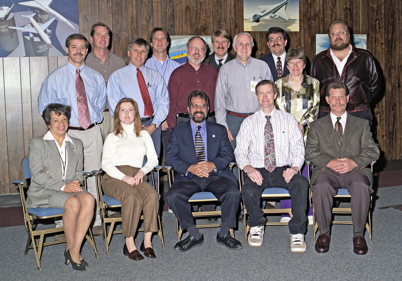
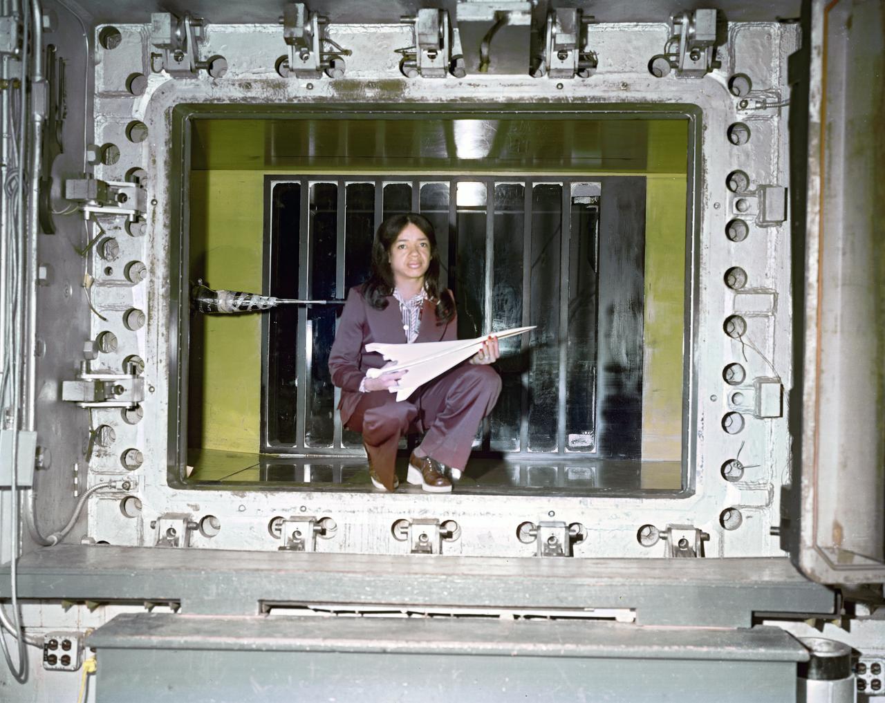
High Speed Research Program/Tu-144 Project Team. Christine Darden in front row first person on the left.
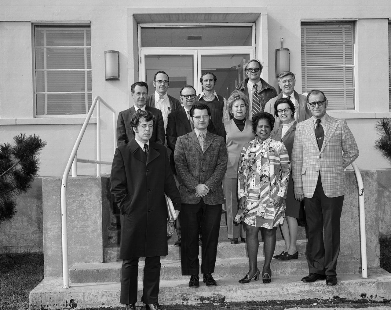
Photograph taken February 06, 1974. High Speed Aircraft Division Personnel, Mary Jackson is one of the people in the front row of this group. Mary Jackson belonged to the Theoretical Performance Group, High Speed Aircraft Division, Office of Director for Aeronautics at time of photo. First row: Steve Wornom, Dick Barnwell, Mary Jackson, and Bud Bobbitt; Second row: Bernie Klunker, Perry Newman, Branch secretary, Frances Keeter, and Ruby Davis, Branch mathematician; Third row: Dennis Allison, Jim Keller, Jerry South, and Cas Czarnecki.
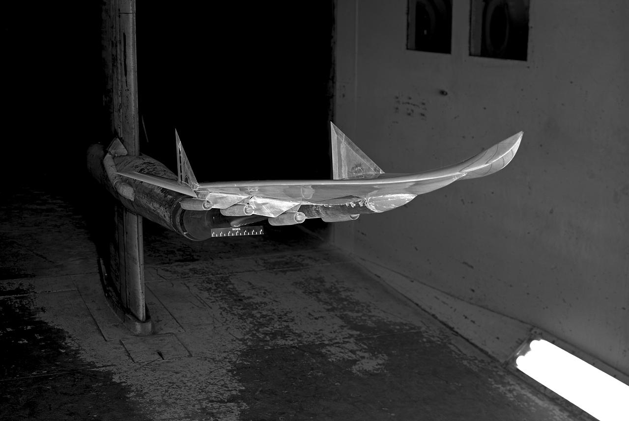
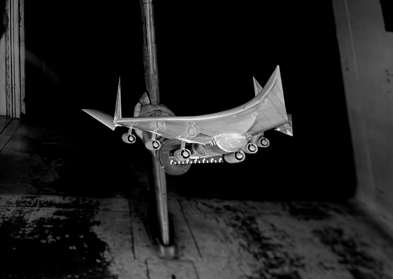
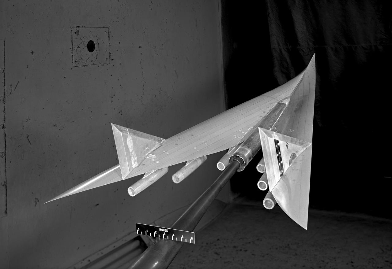
Low Speed investigation of a supersonic transport model with delta wing and delta conard, in the 40x80 Wind Tunnel. R 975 T Zero angel of attack. 3/4 rear view from below.
Hi-Speed impact test simulating space debris hitting an orbiting capsule. A blunt nose 20 millimeter model built of polyethylene hitting a aluminum target at 19,500 feet per second, in a pressure simulated as 100,000 feet altitude.
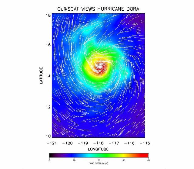
The SeaWinds instrument onboard NASA new QuikScat ocean-viewing satellite captured this image of Hurricane Dora in the eastern tropical Pacific Ocean on August 10, as it was blowing at speeds of nearly 40 meters per second 90 miles per hour.
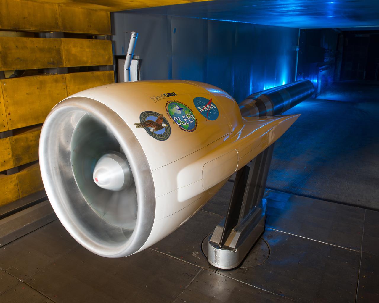
Ultra High Bypass Integrated System Test Testing of an Ultra High Bypass Ratio Turbofan model in the 9-by 15-Foot Low Speed Wind Tunnel. Pratt & Whitney designed the experimental engine to meet new efficiency and noise reduction targets for commercial aircraft set by NASA and the Federal Aviation Administration. The 9-by 15 tests analyzed two noise reduction technologies.
Low Speed investigation of a supersonic transport model in the 40x80 Wind Tunnel. 03/01/1961 R 975 T Zero angel of attack. Supersonic transport with delta wing and delta conard. 3/4 front view.
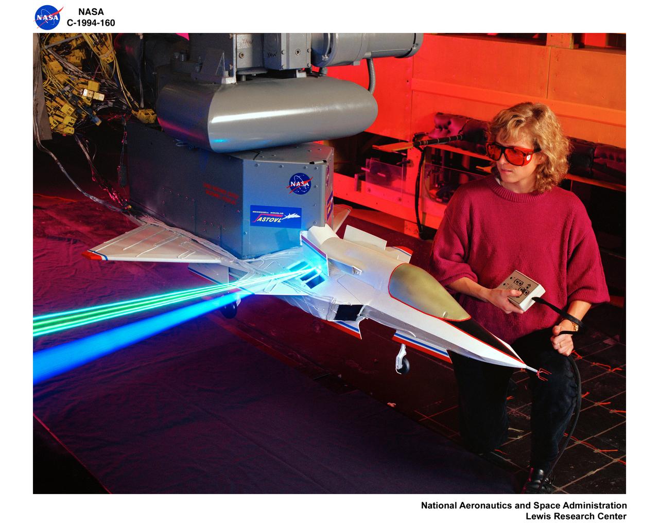
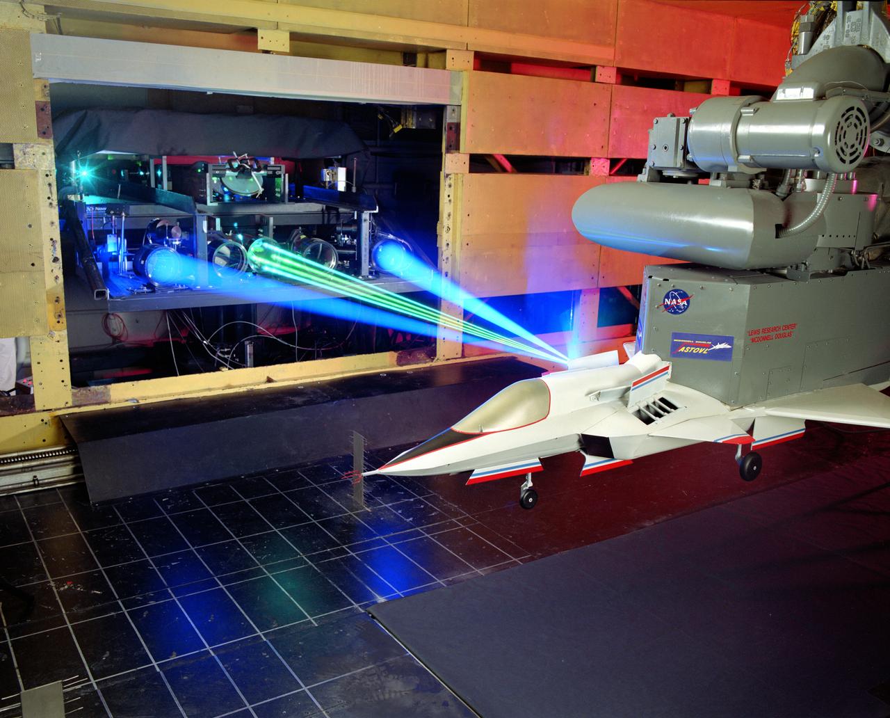
LASER Velocimetry System for Flow Measurement. Advanced Short Takeoff and Vertical Landing, ASTOVL model n the 9x15 foot Low Speed Wind Tunnel, LSWT
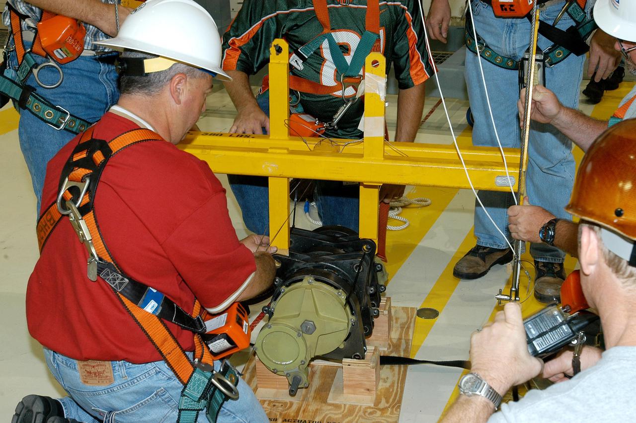
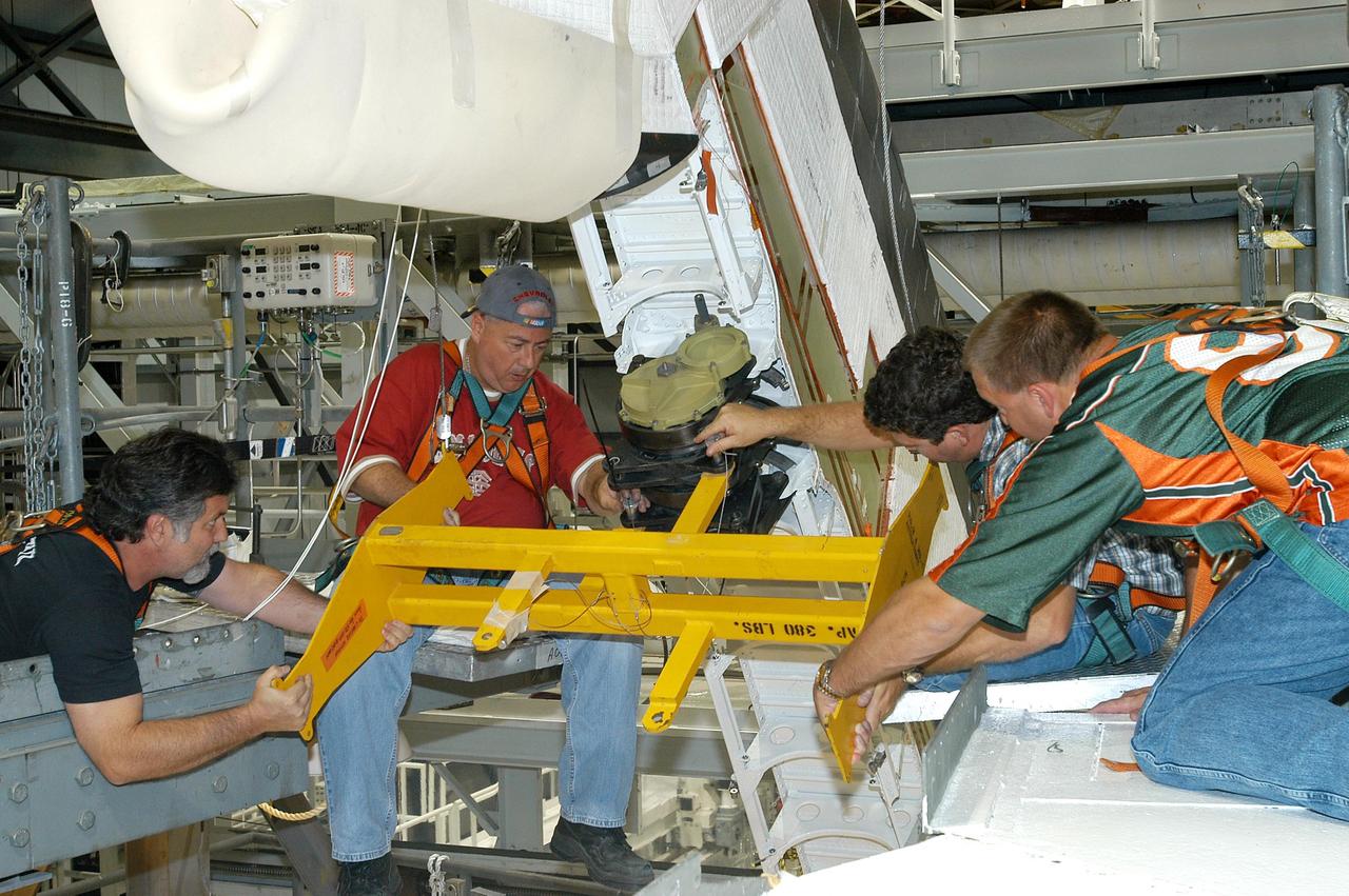
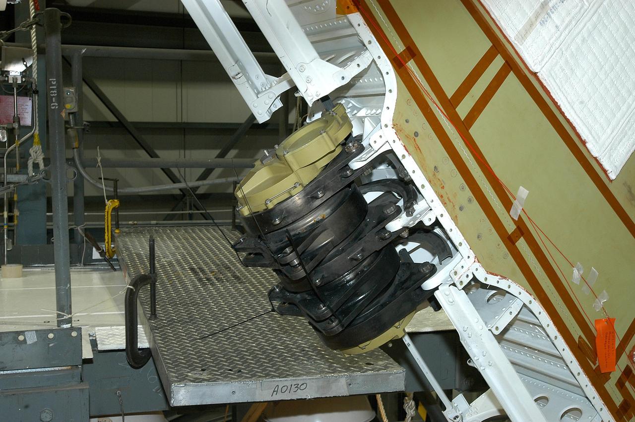
KENNEDY SPACE CENTER, FLA. - Workers in the Orbiter Processing Facility measure the alignment of bearings on a rudder speed brake actuator. Actuators move an orbiter’s rudder, speed brake, elevons and main engines during flight.
The Lowell Observatory's High-speed Imaging Photometer for Occultation rests on its dolly in the lab prior to installation on the SOFIA airborne observatory.
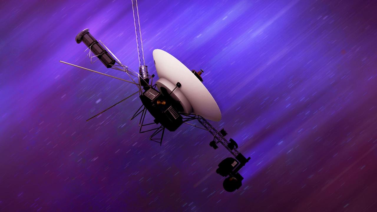
NASA's twin Voyager spacecraft, launched in 1977, are traveling through interstellar space at around 35,000 mph (56,000 kph). This artist's concept depicts one of the probes speeding away. The Voyager spacecraft were built by NASA's Jet Propulsion Laboratory, which continues to operate both. JPL is a division of Caltech in Pasadena, California. The Voyager missions are a part of the NASA Heliophysics System Observatory, sponsored by the Heliophysics Division of the agency's Science Mission Directorate in Washington. For more information about the Voyager spacecraft, visit https://science.nasa.gov/mission/voyager/. https://photojournal.jpl.nasa.gov/catalog/PIA26353
KENNEDY SPACE CENTER, FLA. - Workers in the Orbiter Processing Facility settle into place one of two rudder speed brake actuators onto a table to measure the alignment of its bearings. The actuators move an orbiter’s rudder, speed brake, elevons and main engines during flight.
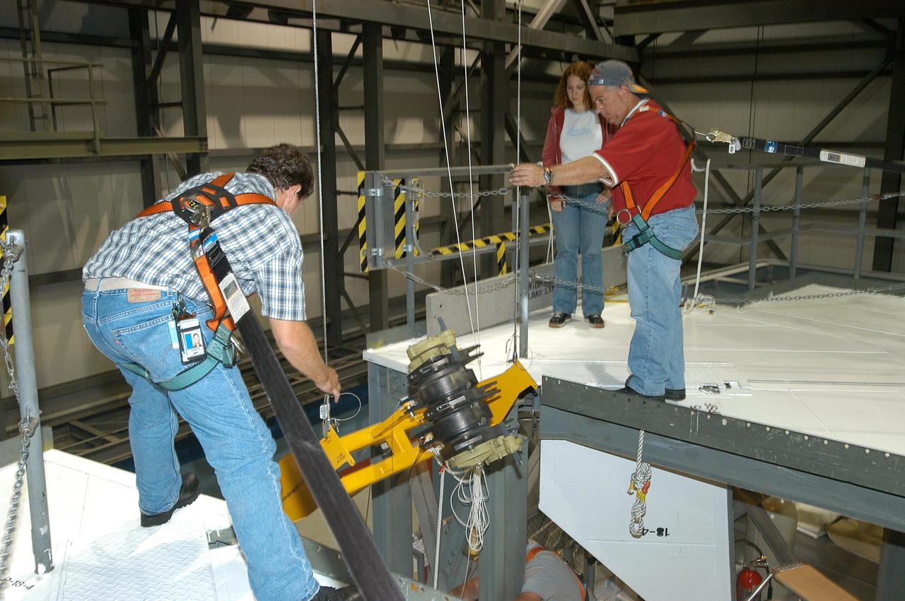
KENNEDY SPACE CENTER, FLA. - Workers in the Orbiter Processing Facility get ready to measure the alignment of the bearings on the rudder speed brake actuators sitting on the floor in the foreground. The actuators move an orbiter’s rudder, speed brake, elevons and main engines during flight.
KENNEDY SPACE CENTER, FLA. - Workers in the Orbiter Processing Facility stand by while another guides the lifting of one of two rudder speed brake actuators onto a table to measure the alignment of its bearings. The actuators move an orbiter’s rudder, speed brake, elevons and main engines during flight.
LSAWT\Twin Jet Test with HWB Model\JEDA Measurements Low Speed Aeroacoustic Wind Tunnel\Twin Jet Model System \Hybrid Wing Model Installed\ Measurement Technique: Jet Directional Array (JEDA)
Environmental Portrait of Christine M. Darden. Sonic boom researcher, HSR, High Speed Research
Environmental Portrait of Christine M. Darden. Sonic boom researcher, HSR, High Speed Research
NASA Phoenix Mars Lander will enter the Martian atmosphere at hypersonic speeds.
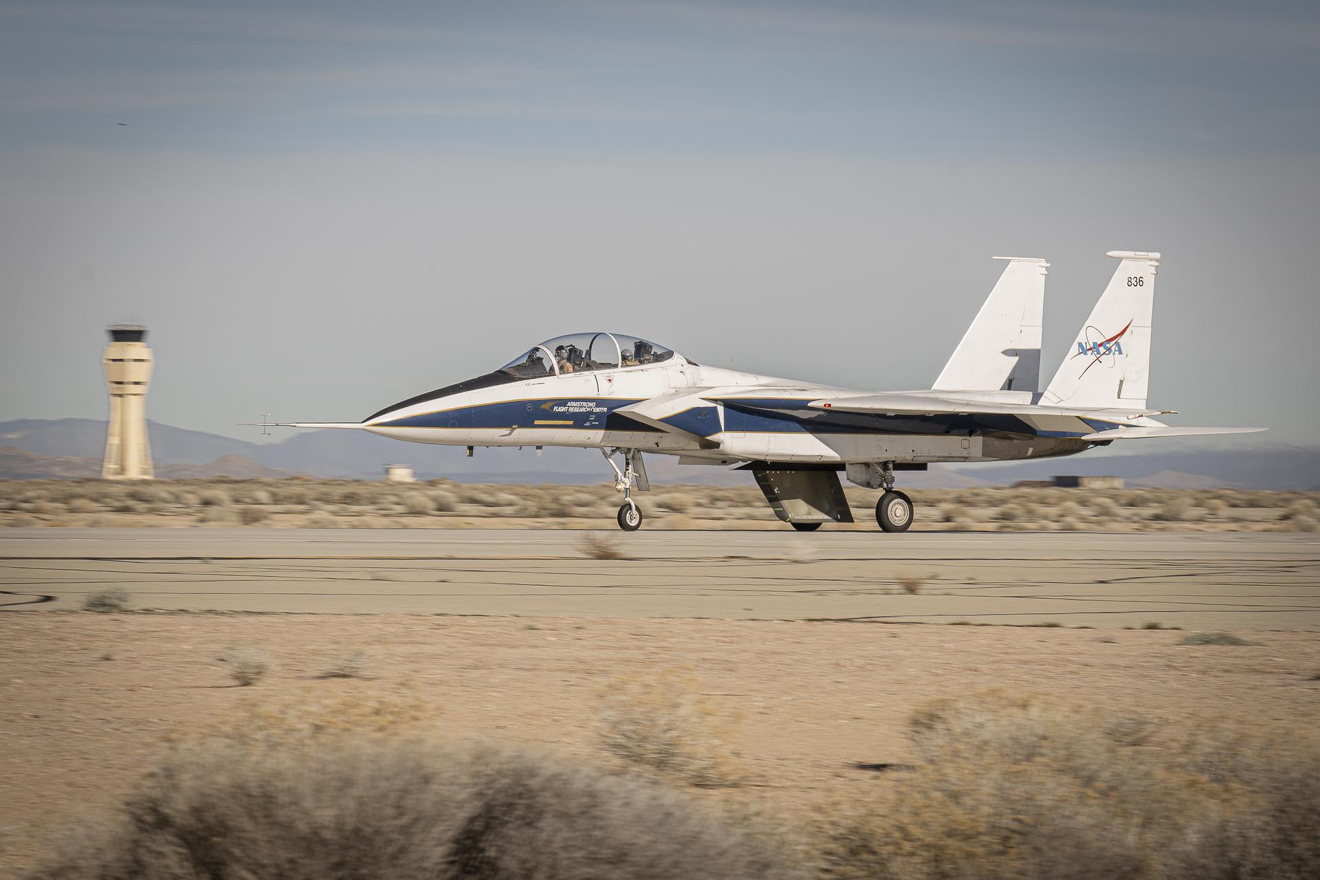
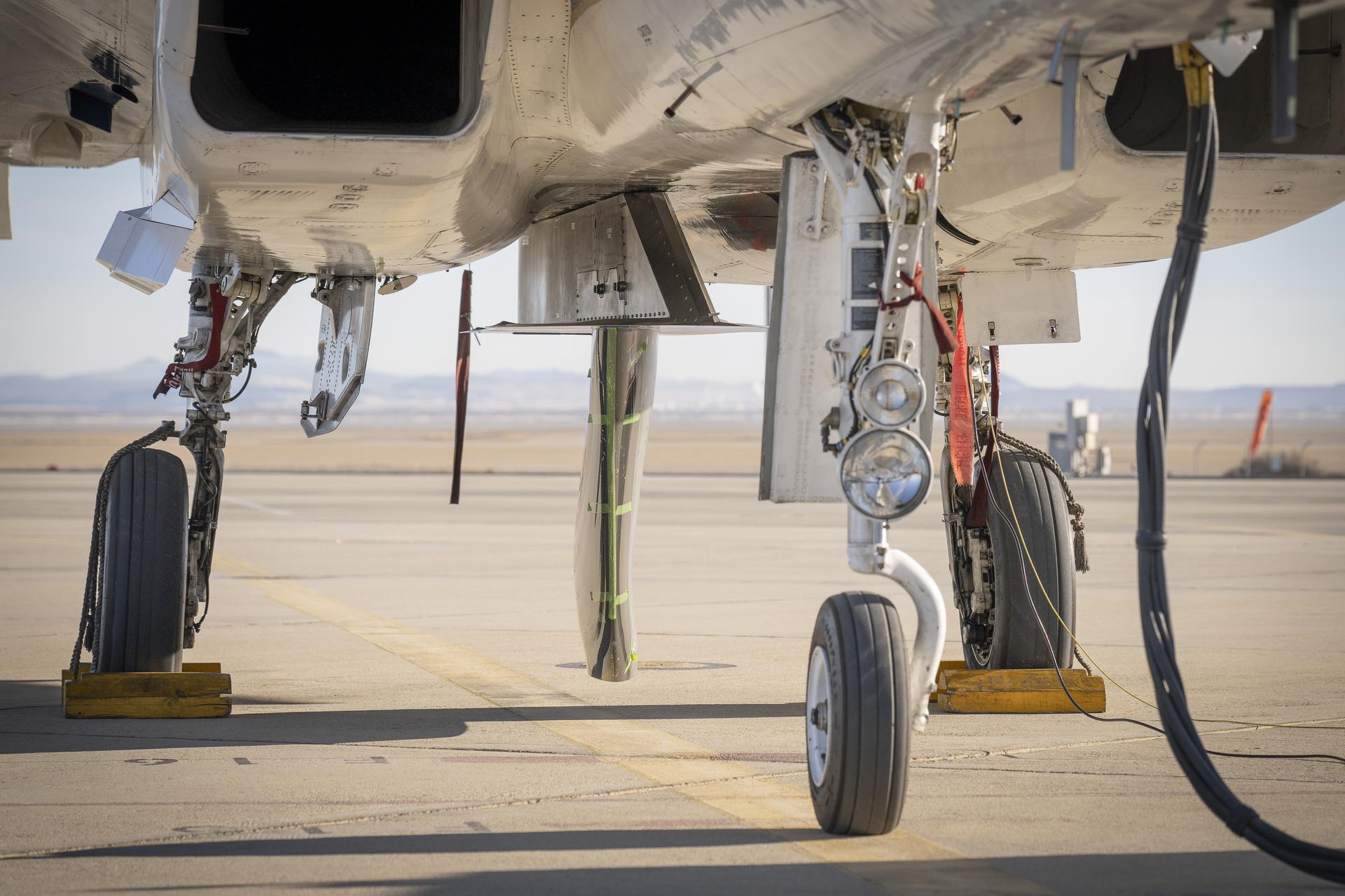
NASA’s Cross Flow Attenuated Natural Laminar Flow (CATNLF) scale model completes its first major milestone – high-speed taxi test – Tuesday, Jan. 12, 2026, at Edwards Air Force Base in California. NASA’s F-15 research aircraft, with the 3-foot-tall test article mounted on its underside, reached speeds of approximately 144 mph during testing. If successful, the technology could be applied to future commercial aircraft to improve efficiency and potentially reduce fuel consumption.
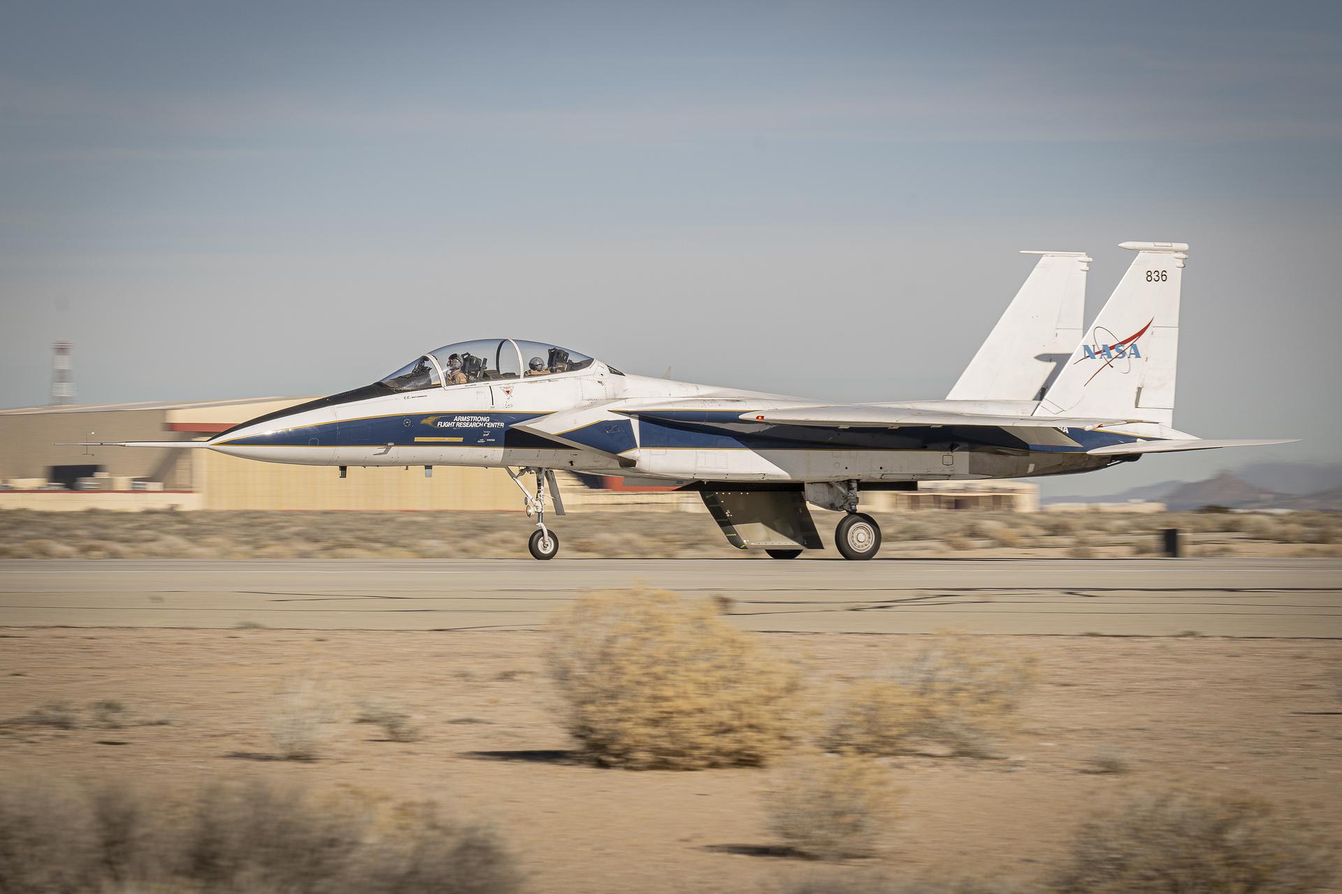
NASA’s Cross Flow Attenuated Natural Laminar Flow (CATNLF) scale model completes its first major milestone – high-speed taxi test – Tuesday, Jan. 12, 2026, at Edwards Air Force Base in California. NASA’s F-15 research aircraft, with the 3-foot-tall test article mounted on its underside, reached speeds of approximately 144 mph during testing. If successful, the technology could be applied to future commercial aircraft to improve efficiency and potentially reduce fuel consumption.
Interior view of the slotted throat test section installed in the 8-Foot High Speed Tunnel (HST) in 1950. The slotted region is about 160 inches in length. In this photograph, the sting-type model support is seen straight on. In a NASA report, the test section is described as follows: The test section of the Langley 8-foot transonic tunnel is dodecagonal in cross section and has a cross-sectional area of about 43 square feet. Longitudinal slots are located between each of the 12 wall panels to allow continuous operation through the transonic speed range. The slots contain about 11 percent of the total periphery of the test section. Six of the twelve panels have windows in them to allow for schlieren observations. The entire test section is enclosed in a hemispherical shaped chamber. John Becker noted that the tunnel s final achievement was the development and use in routine operations of the first transonic slotted throat. The investigations of wing-body shapes in this tunnel led to Whitcomb s discovery of the transonic area rule. James Hansen described the origins of the the slotted throat as follows: In 1946 Langley physicist Ray H. Wright conceived a way to do transonic research effectively in a wind tunnel by placing slots in the throat of the test section. The concept for what became known as the slotted-throat or slotted-wall tunnel came to Wright not as a solution to the chronic transonic problem, but as a way to get rid of wall interference (i.e., the mutual effect of two or more meeting waves or vibrations of any kind caused by solid boundaries) at subsonic speeds. For most of the year before Wright came up with this idea, he had been trying to develop a theoretical understanding of wall interference in the 8-Foot HST, which was then being repowered for Mach 1 capability. When Wright presented these ideas to John Stack, the response was enthusiastic but neither Wright nor Stack thought of slotted-throats as a solution to the transonic problem, only the wall interference problem. It was an accidental discovery which showed that slotted throats might solve the transonic problem. Most engineers were skeptical but Stack persisted. Initially, plans were to modify the 16-Foot tunnel but in the spring of 1948, Stack announced that the 8-Foot HST would also be modified. As Hansen notes: The 8-Foot HST began regular transonic operations for research purposes on 6 October 1950. The concept was a success and led to plans for a new wind tunnel which would be known as the 8-Foot Transonic Pressure Tunnel. -- Published in U.S., National Advisory Committee for Aeronautics, Characteristics of Nine Research Wind Tunnels of the Langley Aeronautical Laboratory, 1957, pp. 17, 22 James R. Hansen, Engineer in Charge, NASA SP-4305, p. 454 and Chapter 11, The Slotted Tunnel and the Area Rule.
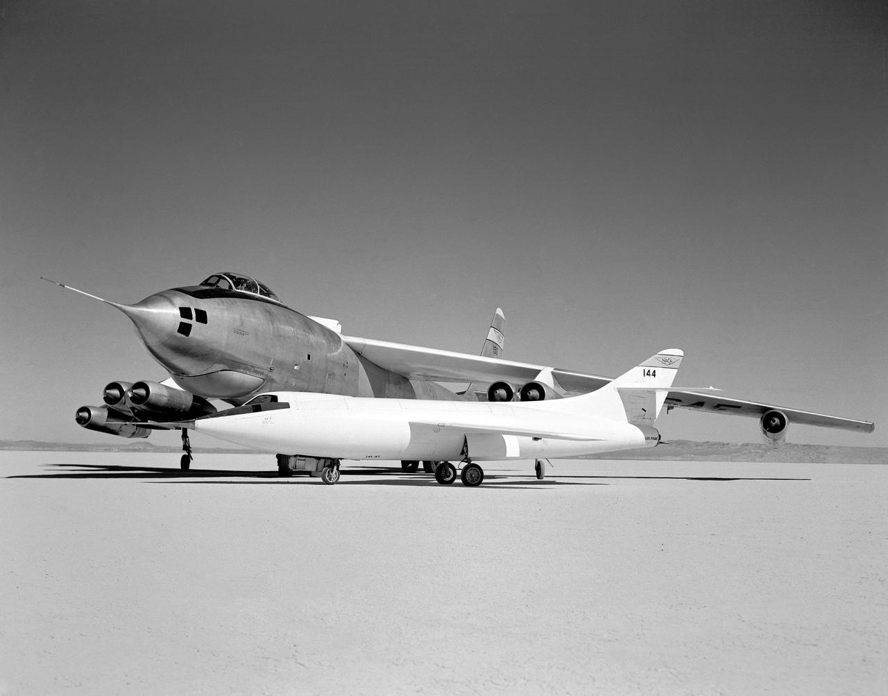
In 1954 this photo of two swept wing airplanes was taken on the ramp of NACA High-Speed Flight Research Station. The Douglas D-558-ll is a research aircraft while the Boeing B-47A Stratojet is a production bomber and very different in size. Both contributed to the studies for swept back wing research.
NASA GLENN/NASA LANGLEY LOADS COMPARISON TEST WITH 6 COMPONENT FORCE/MOMENT BALANCE AND 1.7% HIGH SPEED RESEARCH MODEL 5.

NASA GLENN/NASA LANGLEY LOADS COMPARISON TEST WITH 6 COMPONENT FORCE/MOMENT BALANCE AND 1.7% HIGH SPEED RESEARCH MODEL 5.
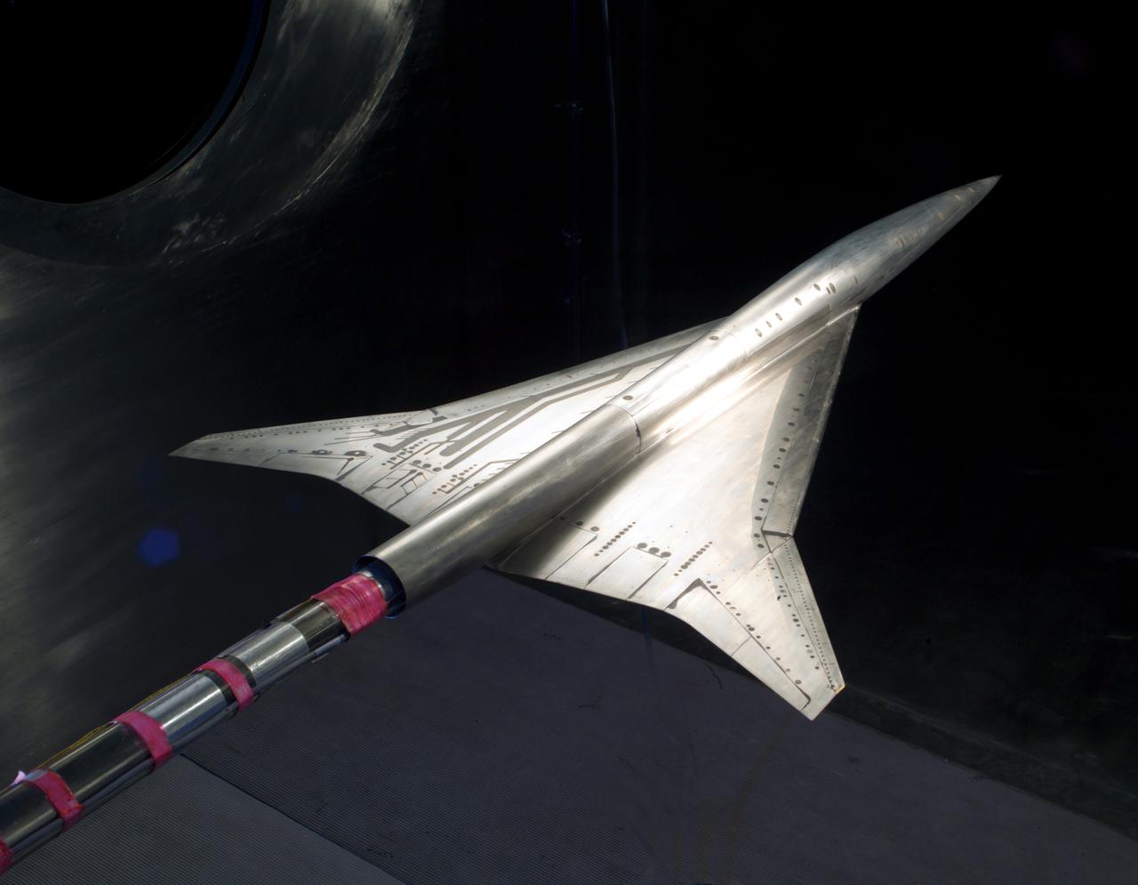
NASA GLENN/NASA LANGLEY LOADS COMPARISON TEST WITH 6 COMPONENT FORCE/MOMENT BALANCE AND 1.7% HIGH SPEED RESEARCH MODEL 5.
NASA GLENN/NASA LANGLEY LOADS COMPARISON TEST WITH 6 COMPONENT FORCE/MOMENT BALANCE AND 1.7% HIGH SPEED RESEARCH MODEL 5.
NASA GLENN/NASA LANGLEY LOADS COMPARISON TEST WITH 6 COMPONENT FORCE/MOMENT BALANCE AND 1.7% HIGH SPEED RESEARCH MODEL 5.
NASA GLENN/NASA LANGLEY LOADS COMPARISON TEST WITH 6 COMPONENT FORCE/MOMENT BALANCE AND 1.7% HIGH SPEED RESEARCH MODEL 5.
NASA GLENN/NASA LANGLEY LOADS COMPARISON TEST WITH 6 COMPONENT FORCE/MOMENT BALANCE AND 1.7% HIGH SPEED RESEARCH MODEL 5.
The 9x15 low speed tunnel tests take off and landing of aircraft. The laser velocimetry system for flow measurement show here, with the color blue and green lasers, measures engine exhaust that comes back up from the ground. The STOVL model n the 9x15 low speed wind tunnel, building 39, is similar to the British Harrier aircraft.
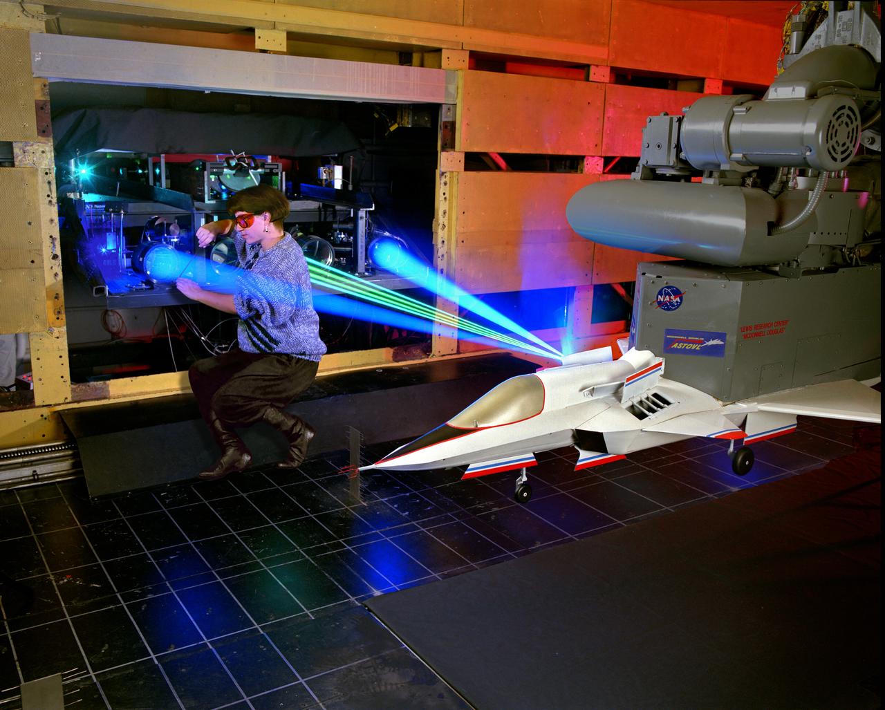
The 9x15 low speed tunnel tests take off and landing of aircraft. The laser velocimetry system for flow measurement show here, with the color blue and green lasers, measures engine exhaust that comes back up from the ground. The STOVL model n the 9x15 low speed wind tunnel, building 39, is similar to the British Harrier aircraft.
In this 1950 view of the left side of the NACA High-Speed Flight Research Station's X-4 research aircraft, the low swept wing and horizontal taillest design are seen. The X-4 Bantam, a single-place, low swept-wing, semi-tailless aircraft, was designed and built by Northrop Aircraft, Inc. It had no horizontal tail surfaces and its mission was to obtain in-flight data on the stability and control of semi-tailless aircraft at high subsonic speeds.
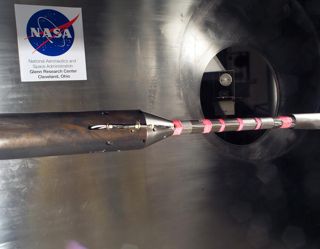
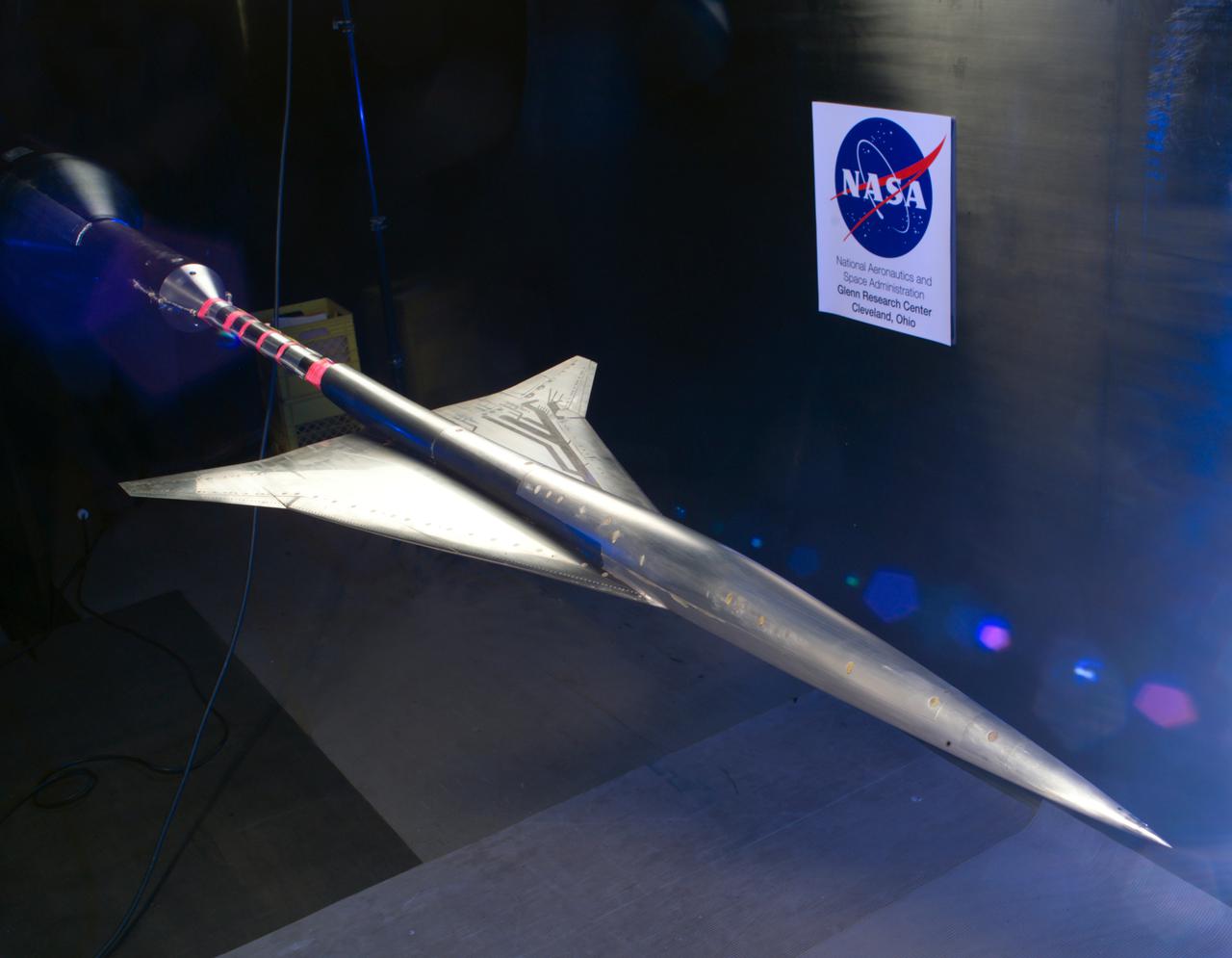
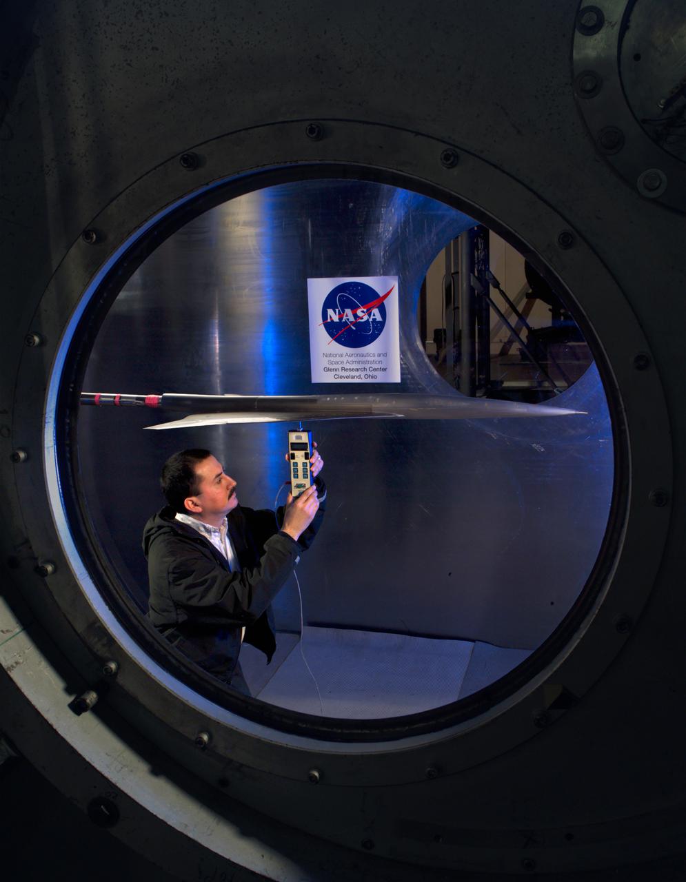
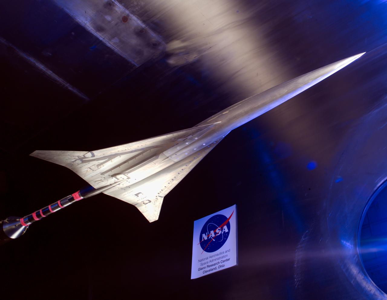
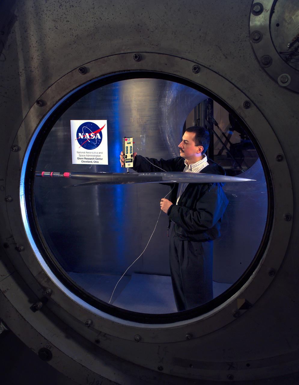
NASA Glenn/NASA Langley, Loads Comparison Test With 6 Component Force/Moment Balance and 1.7% High Speed Research, HSR Model 5. In the Glenn Research Center 10x10 Foot Supersonic Wind Tunnel, SWT
NASA GLENN/NASA LANGLEY LOADS COMPARISON TEST WITH 6 COMPONENT FORCE/MOMENT BALANCE AND 1.7% HIGH SPEED RESEARCH MODEL 5. in the 10x10 super sonic wind tunnel
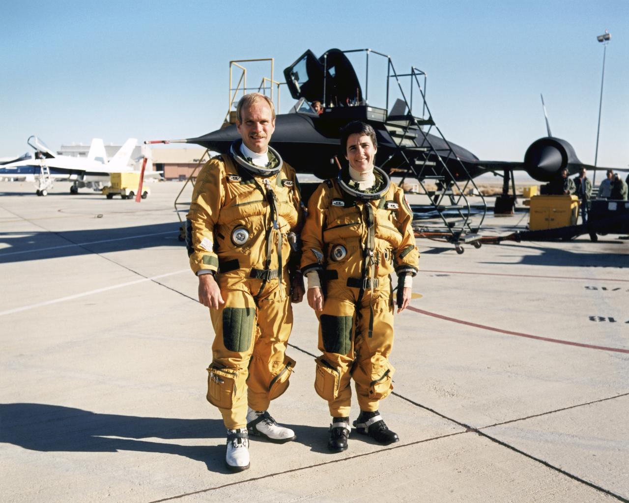
The husband-and-wife team of Bob Meyer and Marta Bohn-Meyer flew as flight test engineers on high-speed experiments flown on the triple-sonic SR-71 at NASA Dryden.

This artist concept shows a celestial body about the size of our moon slamming at great speed into a body the size of Mercury. NASA Spitzer found evidence that a high-speed collision of this sort occurred a few thousand years ago around a young star.
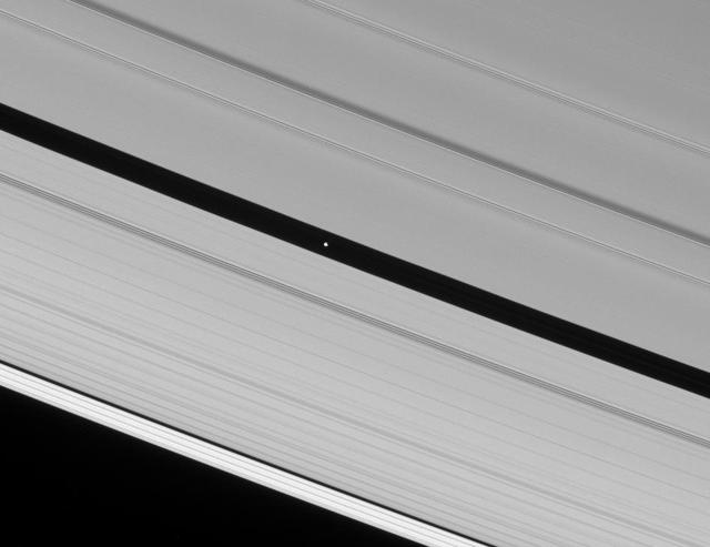
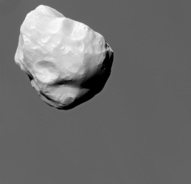
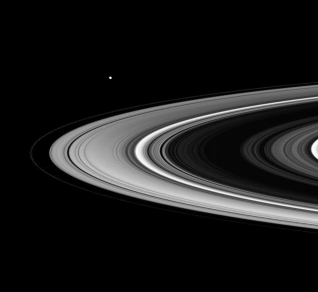
The Cassini spacecraft spies Pan speeding through the Encke Gap, its own private path around Saturn

This illustration depicts the shearing of an initially circular cloud of debris as a result of the particles in the cloud having differing orbital speeds around Saturn.

This artist concept shows a possible explosion resulting from a high-speed collision between a space rock and Jupiter moon Europa.
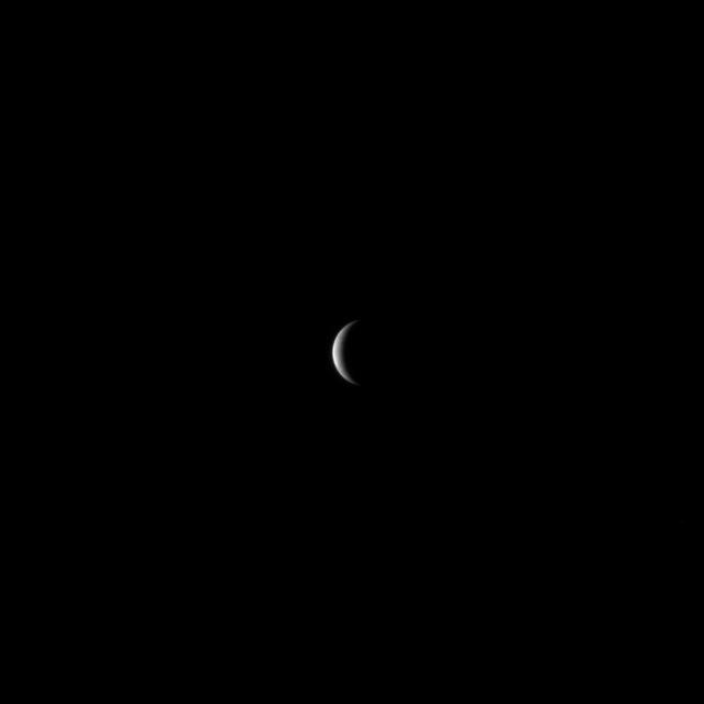
NASA MESSENGER spacecraft continued to speed toward Mercury, preparing for its closest approach to the planet on Monday, January 14, 2008.
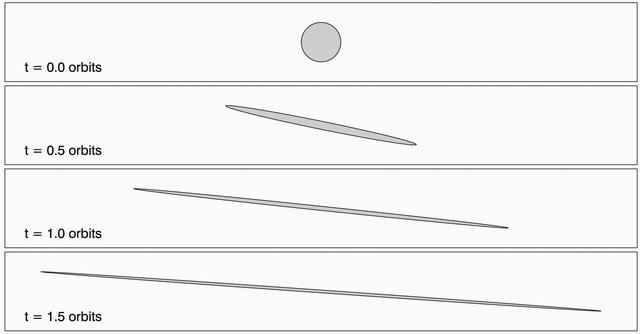
This animation depicts the shearing of an initially circular cloud of debris as a result of the particles in the cloud having differing orbital speeds around Saturn.
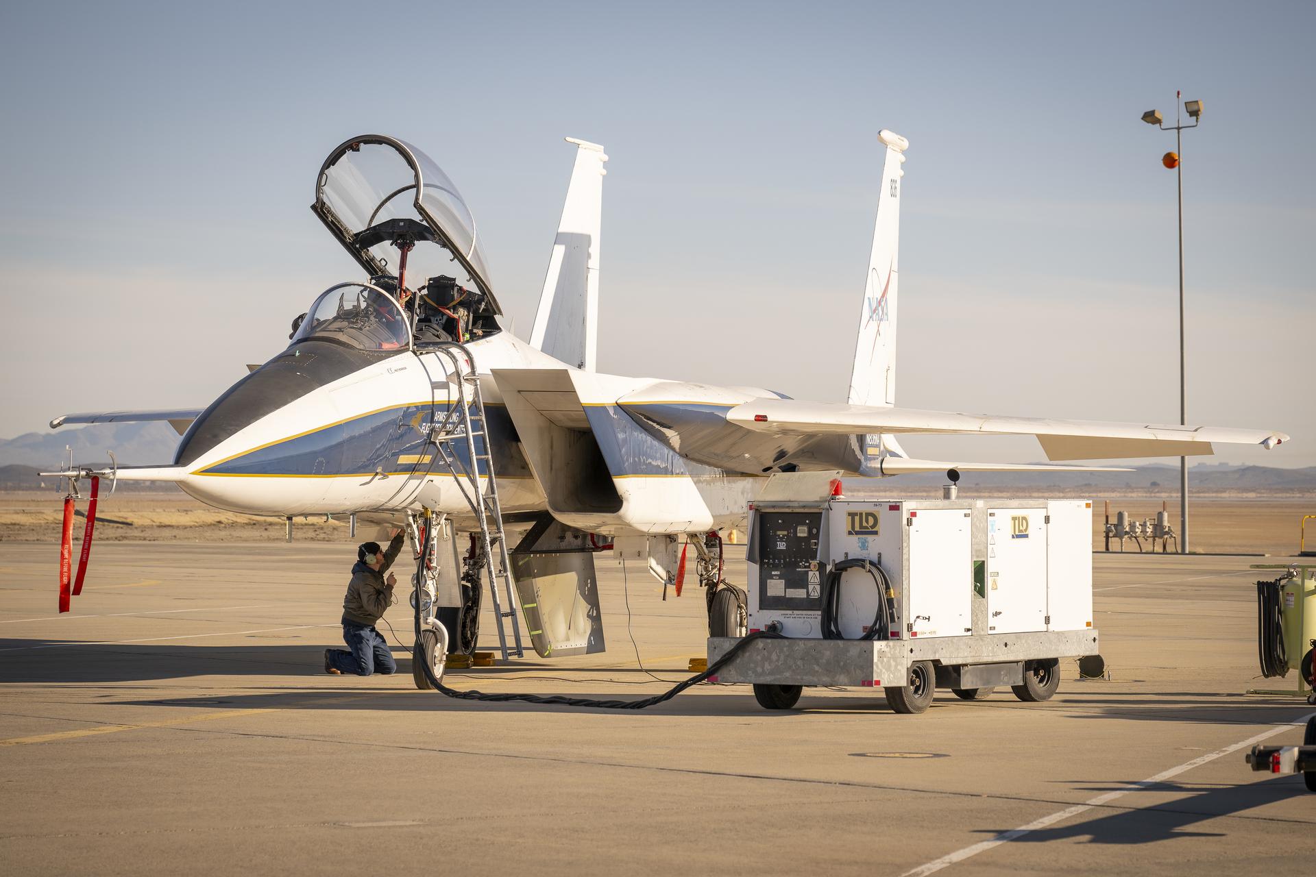
NASA ground crew prepares the agency’s F-15 research aircraft and Cross Flow Attenuated Natural Laminar Flow (CATNLF) test article ahead of its first high-speed taxi test on Tuesday, Jan. 12, 2026, at NASA’s Armstrong Flight Research Center in Edwards, California. The CATNLF design aims to reduce drag on wing surfaces to improve efficiency and, in turn, reduce fuel burn.
NASA’s Cross Flow Attenuated Natural Laminar Flow test article is mounted beneath the agency’s F-15 research aircraft ahead of the design’s high-speed taxi test on Tuesday, Jan. 12, 2026, at NASA’s Armstrong Flight Research Center in Edwards, California. The 3-foot-tall scale model is designed to increase a phenomenon known as laminar flow and reduce drag, improving efficiency in large, swept wings like those found on most commercial aircraft.
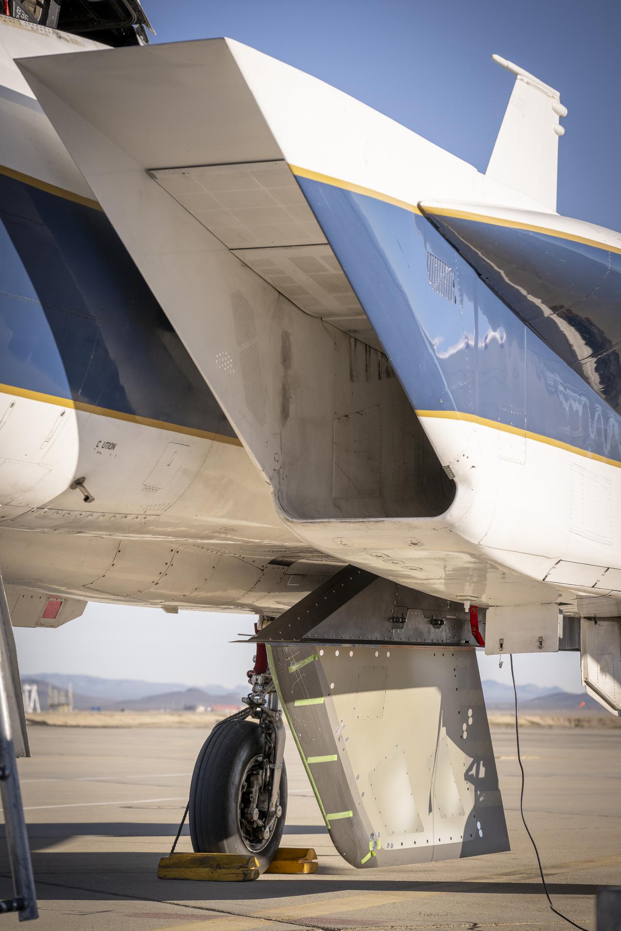
NASA’s Cross Flow Attenuated Natural Laminar Flow test article is mounted beneath the agency’s F-15 research aircraft ahead of the design’s high-speed taxi test on Tuesday, Jan. 12, 2026, at NASA’s Armstrong Flight Research Center in Edwards, California. The 3-foot-tall scale model is designed to increase a phenomenon known as laminar flow and reduce drag, improving efficiency in large, swept wings like those found on most commercial aircraft.
NASA’s Cross Flow Attenuated Natural Laminar Flow test article is mounted beneath the agency’s F-15 research aircraft ahead of the design’s high-speed taxi test on Tuesday, Jan. 12, 2026, at NASA’s Armstrong Flight Research Center in Edwards, California. The 3-foot-tall scale model is designed to increase a phenomenon known as laminar flow and reduce drag, improving efficiency in large, swept wings like those found on most commercial aircraft.
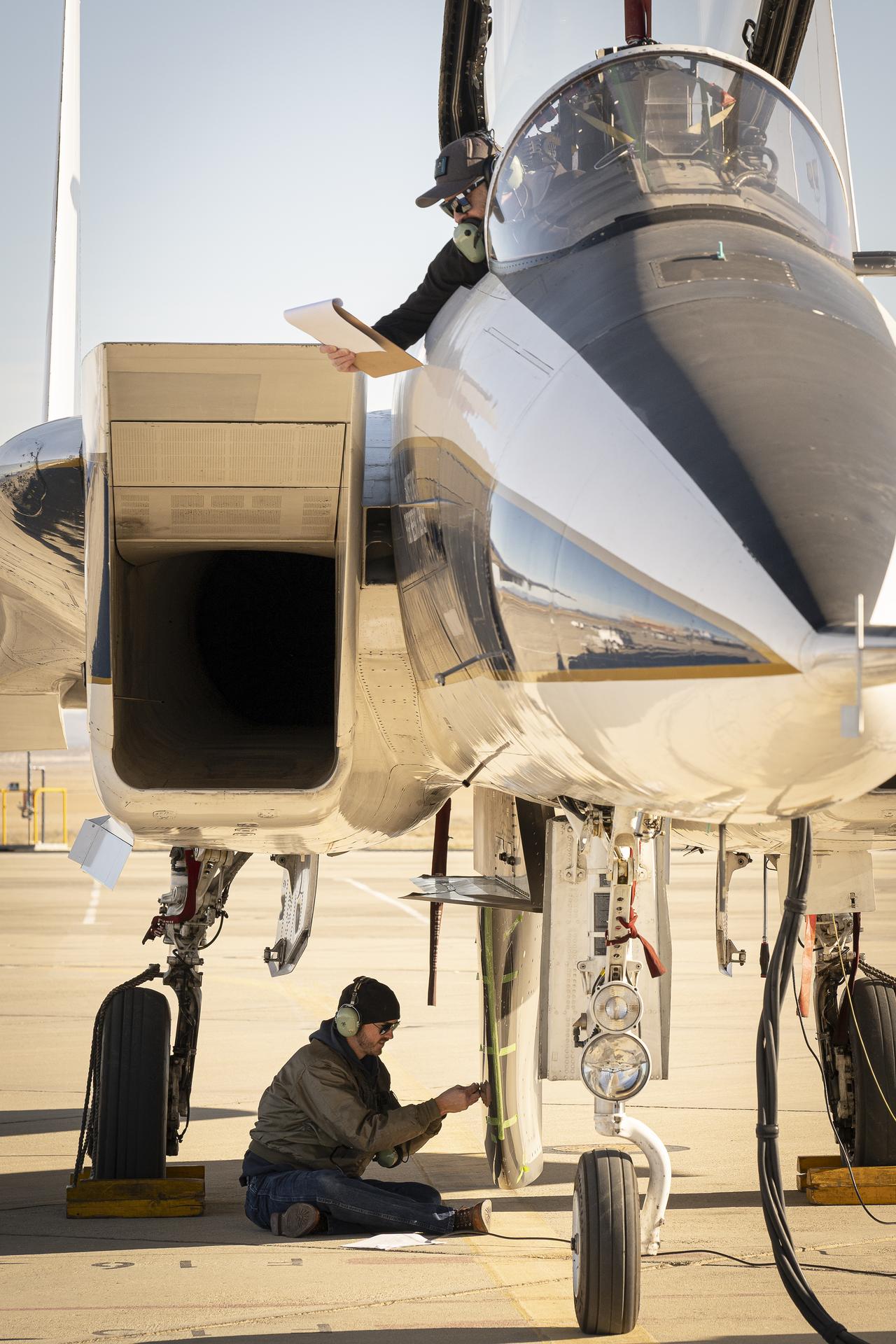
NASA ground crew prepares the agency’s F-15 research aircraft and Cross Flow Attenuated Natural Laminar Flow (CATNLF) test article ahead of its first high-speed taxi test on Tuesday, Jan. 12, 2026, at NASA’s Armstrong Flight Research Center in Edwards, California. The CATNLF design aims to reduce drag on wing surfaces to improve efficiency and, in turn, reduce fuel burn.
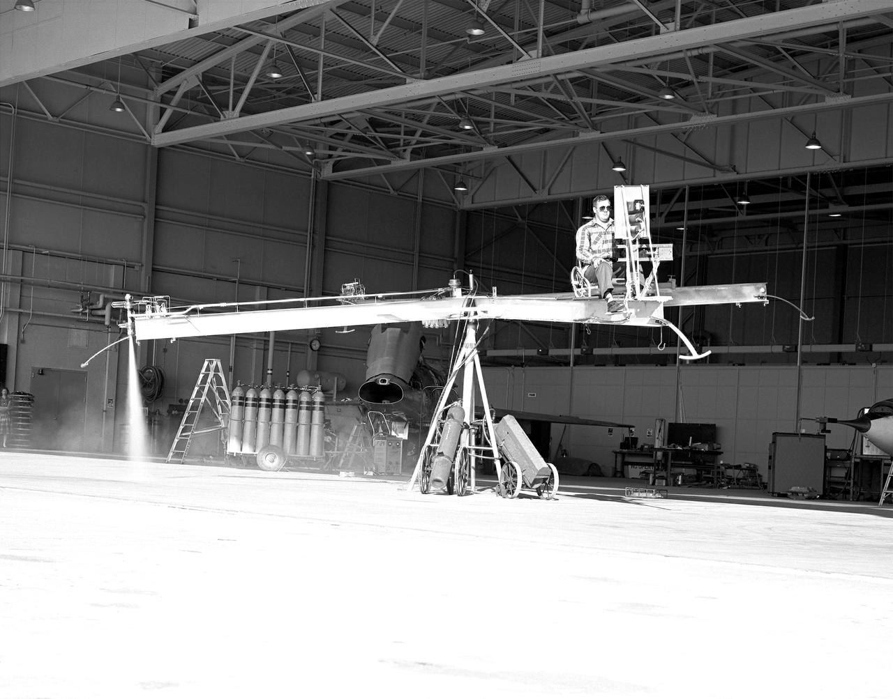
NACA High-Speed Flight Station test pilot Stan Butchart flying the Iron Cross, the mechanical reaction control simulator. High-pressure nitrogen gas expanded selectively, by the pilot, through the small reaction control thrusters maneuvered the Iron Cross through the three axes. The exhaust plume can be seen from the aft thruster. The tanks containing the gas can be seen on the cart at the base of the pivot point of the Iron Cross. NACA technicians built the iron-frame simulator, which matched the inertia ratios of the Bell X-1B airplane, installing six jet nozzles to control the movement about the three axes of pitch, roll, and yaw.
Flight engineers Marta Bohn-Meyer and Bob Meyer and pilots Ed Schneider and Rogers Smith flew the triple-sonic SR-71 in high-speed research experiments at NASA Dryden.
The slow-speed wooden propeller and long wings are evident as NASA's YO-3A acoustics research aircraft performs a low-level flyover at Edwards Air Force Base.
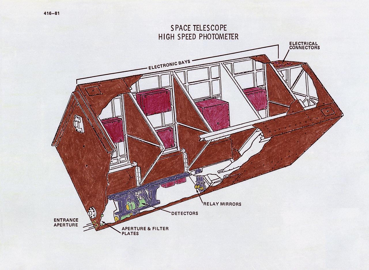
This drawing illustrates the Hubble Space Telescope's (HST's) High Speed Photometer (HSP). The HSP measures the intensity of starlight (brightness), which will help determine astronomical distances. Its principal use will be to measure extremely-rapid variations or pulses in light from celestial objects, such as pulsating stars. The HSP produces brightness readings. Light passes into one of four special signal-multiplying tubes that record the data. The HSP can measure energy fluctuations from objects that pulsate as rapidly as once every 10 microseconds. From HSP data, astronomers expect to learn much about such mysterious objects as pulsars, black holes, and quasars. The purpose of the HST, the most complex and sensitive optical telescope ever made, is to study the cosmos from a low-Earth orbit. By placing the telescope in space, astronomers are able to collect data that is free of the Earth's atmosphere. The HST views galaxies, stars, planets, comets, possibly other solar systems, and even unusual phenomena such as quasars, with 10 times the clarity of ground-based telescopes. The HST was deployed from the Space Shuttle Discovery (STS-31 mission) into Earth orbit in April 1990. The Marshall Space Flight Center had responsibility for design, development, and construction of the HST. The Perkin-Elmer Corporation, in Danbury, Cornecticut, developed the optical system and guidance sensors.
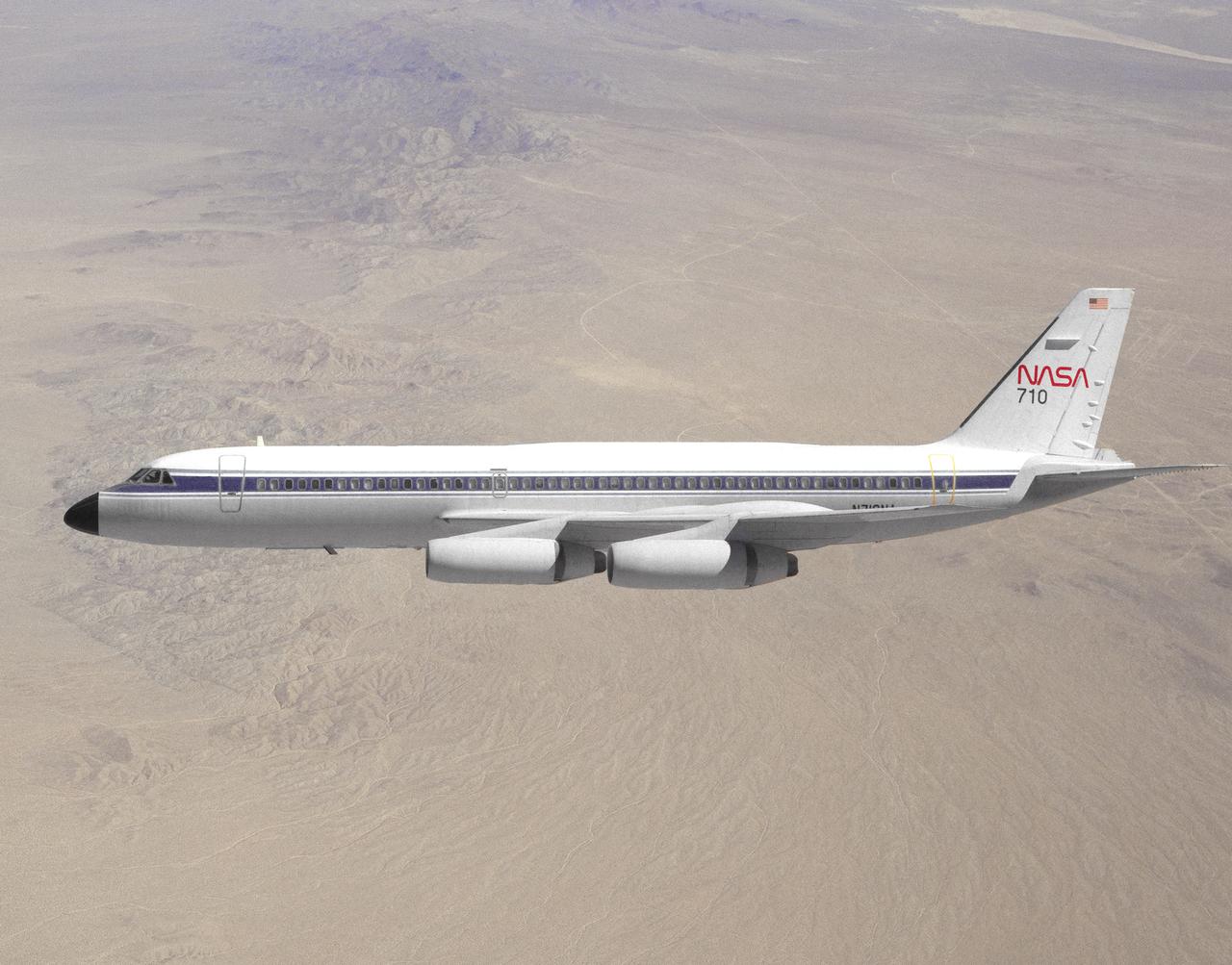
NASA 710, a Convair 990 transport aircraft formerly used for medium altitude atmospheric research, cruises over the Mojave Desert near NASA's Dryden Flight Research Center, Edwards, California. The flight was a final speed calibration run prior to the start of extensive modifications that turned the aircraft into a landing systems research aircraft to test and evaluate brakes and landing gear systems on space shuttles and also conventional aircraft. Research flights with the aircraft began in April of 1993. Testing of shuttle components lasted into fiscal year 1995.
Famed astronaut Neil A. Armstrong – the first person to set foot on the Moon during the historic Apollo 11 mission in July 1969 – spent seven years as a research pilot at the NACA-NASA High-Speed Flight Station, now NASA’s Armstrong Flight Research Center in Edwards, California, before joining the space program. During his tenure, Armstrong was actively engaged in both the piloting and engineering aspects of numerous NASA programs and projects.
The X-2, initially an Air Force program, was scheduled to be transferred to the civilian National Advisory Committee for Aeronautics (NACA) for scientific research. The Air Force delayed turning the aircraft over to the NACA in the hope of attaining Mach 3 in the airplane. The service requested and received a two-month extension to qualify another Air Force test pilot, Capt. Miburn "Mel" Apt, in the X-2 and attempt to exceed Mach 3. After several ground briefings in the simulator, Apt (with no previous rocket plane experience) made his flight on 27 September 1956. Apt raced away from the B-50 under full power, quickly outdistancing the F-100 chase planes. At high altitude, he nosed over, accelerating rapidly. The X-2 reached Mach 3.2 (2,094 mph) at 65,000 feet. Apt became the first man to fly more than three times the speed of sound. Still above Mach 3, he began an abrupt turn back to Edwards. This maneuver proved fatal as the X-2 began a series of diverging rolls and tumbled out of control. Apt tried to regain control of the aircraft. Unable to do so, Apt separated the escape capsule. Too late, he attempted to bail out and was killed when the capsule impacted on the Edwards bombing range. The rest of the X-2 crashed five miles away. The wreckage of the X-2 rocket plane was later taken to NACA's High Speed Flight Station for analysis following the crash.
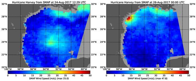
The rapid intensification of Hurricane Harvey is seen in this pair of images of ocean surface wind speeds as observed by the radiometer instrument aboard NASA's Soil Moisture Active Passive (SMAP) satellite at 7:29 a.m. CDT Aug. 24th, 2017 (left) and at 7 p.m. CDT Aug. 26th (right). Color indicates wind speed, with red being highest and blue lowest. The images show Harvey's maximum wind speeds increased from approximately 56 miles per hour (25 meters per second) to about 107 miles per hour (47.8 meters per second) in the 36 hours just before landfall. The higher wind speeds estimated near the mouth of the Mississippi River are erroneous and are due to errors in the ancillary sea-surface-salinity data product used by SMAP to estimate extreme wind speeds. https://photojournal.jpl.nasa.gov/catalog/PIA21884

Jupiter north polar region is coming into view as NASA Juno spacecraft approaches the giant planet. This view of Jupiter was taken on August 27, when Juno was 437,000 miles 703,000 kilometers away. http://photojournal.jpl.nasa.gov/catalog/PIA20895
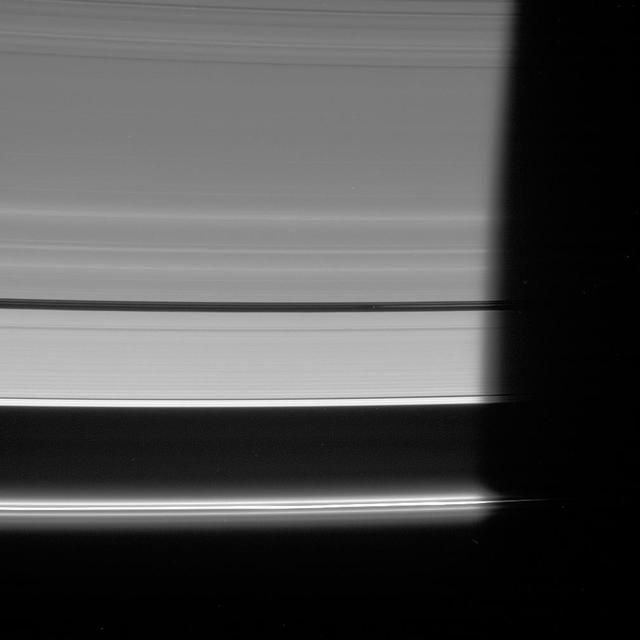
NASA Cassini spacecraft looks down at the unlit side of the rings as Pan heads into Saturn shadow. The moon is accompanied by faint ringlets in the Encke Gap.
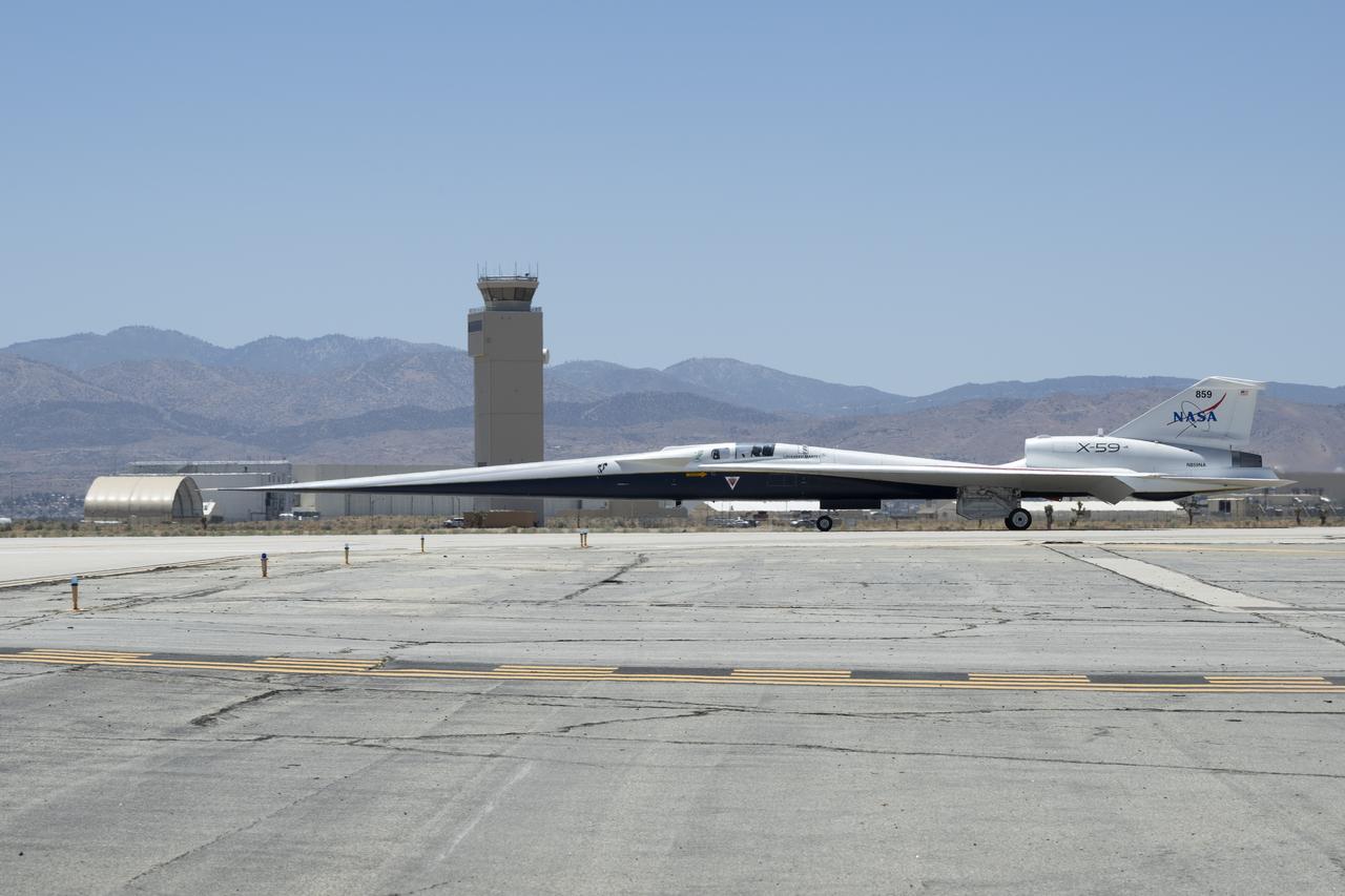
NASA’s X-59 quiet supersonic research aircraft taxis across the runway during a low-speed taxi test at U.S. Air Force Plant 42 in Palmdale, California, on July 10, 2025. The test marks the start of taxi tests and the last series of ground tests before first flight.
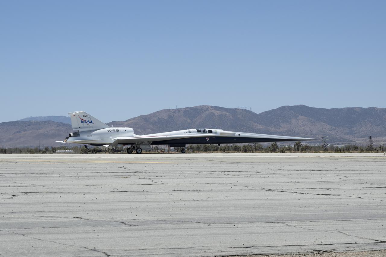
NASA’s X-59 quiet supersonic research aircraft taxis across the runway during a low-speed taxi test at U.S. Air Force Plant 42 in Palmdale, California, on July 10, 2025. The test marks the start of taxi tests and the last series of ground tests before first flight.
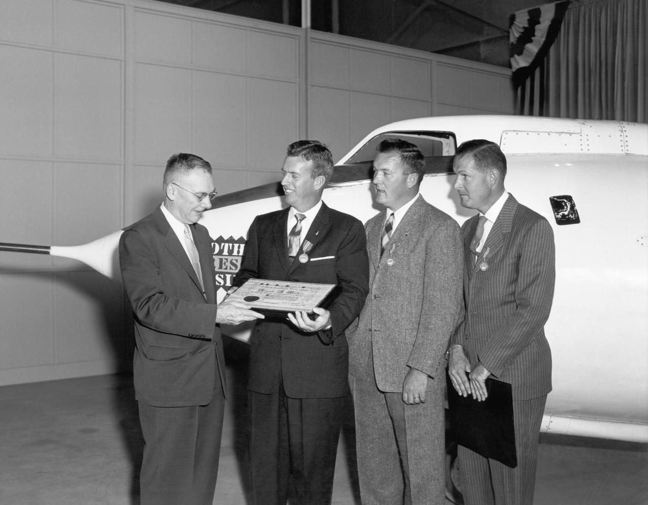
High-Speed Research Station Director Walter C. Williams, NACA pilot A. Scott Crossfield, and Director of Flight Operations Joe Vensel in front of the Douglas D-558-2 after the first Mach 2 flight.
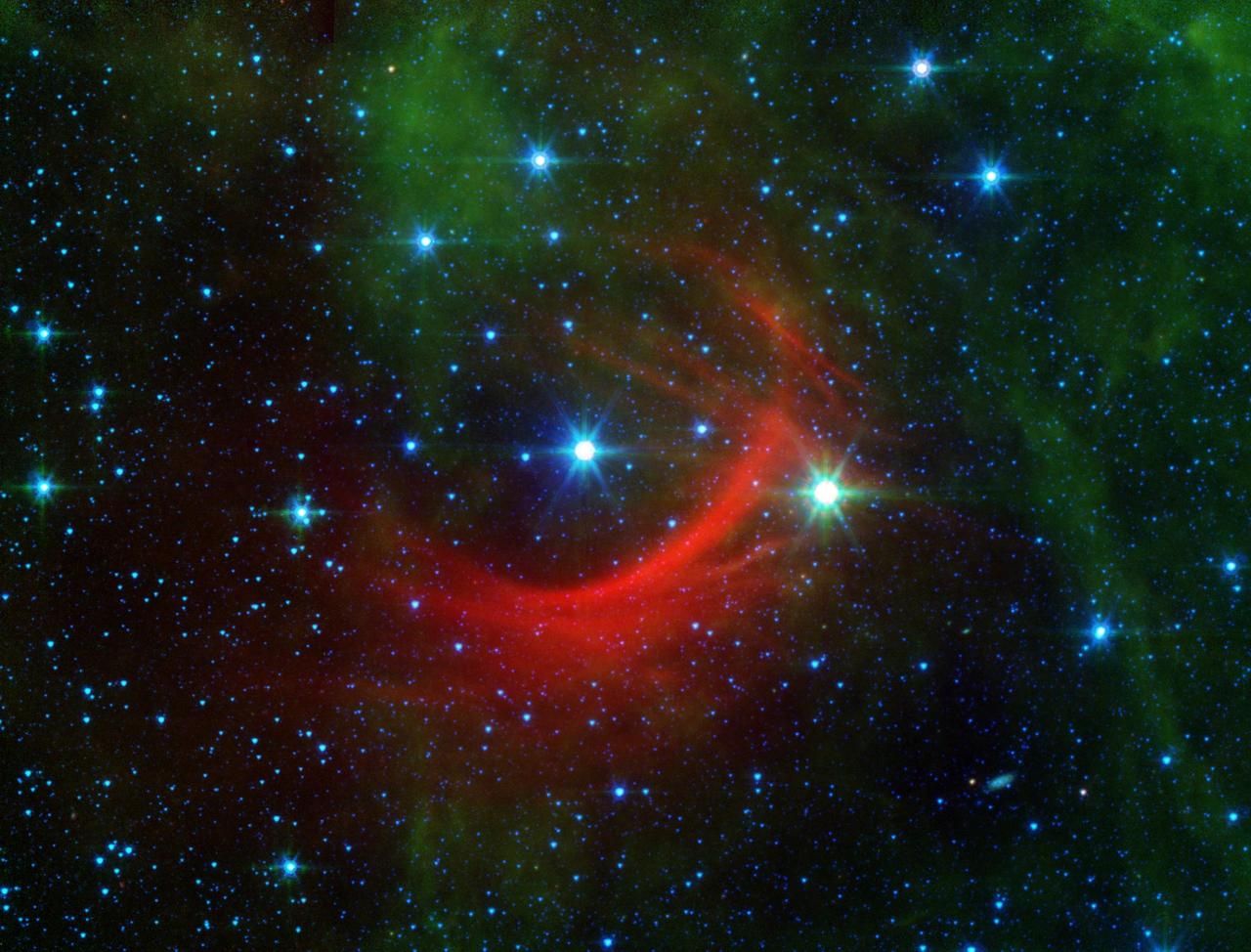
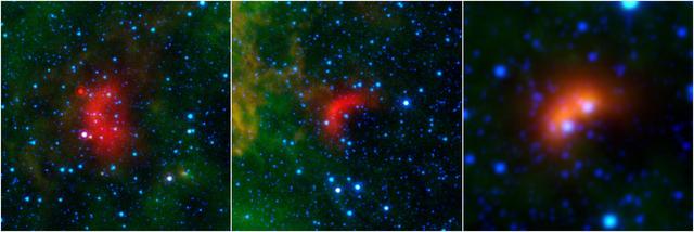
The red arc in this infrared image from NASA Spitzer Space Telescope is a giant shock wave, created by a speeding star known as Kappa Cassiopeiae.
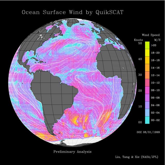
This image shows wind speeds and direction in the Atlantic Ocean on August 1, 1999, gathered by NASA Seawinds radar instrument flying onboard NASA QuikScat satellite.
Prometheus speeds ahead of two dark gores in the F ring inner edge. The ring bright core swerves and twirls in its wake
Although travelling at great speed, NASA Cassini spacecraft managed to capture this close view of Saturn small moon Helene during a flyby on March 3, 2010.

Two bright vortices roll across the cloud-lined face of Saturn, where winds howl at high speeds never experienced on Earth

This image shows wind speeds and direction in the Pacific Ocean on August 1, 1999, gathered by NASA Seawinds radar instrument flying onboard NASA QuikScat satellite.

After NASA Phoenix Mars Lander enters the Martian atmosphere, and is traveling at about 1.7 times the speed of sound, it will deploy its parachute.
This movie begins with a view of the sunlit side of the rings. As the spacecraft speeds from south to north, the rings appear to tilt downward and collapse to a thin plane
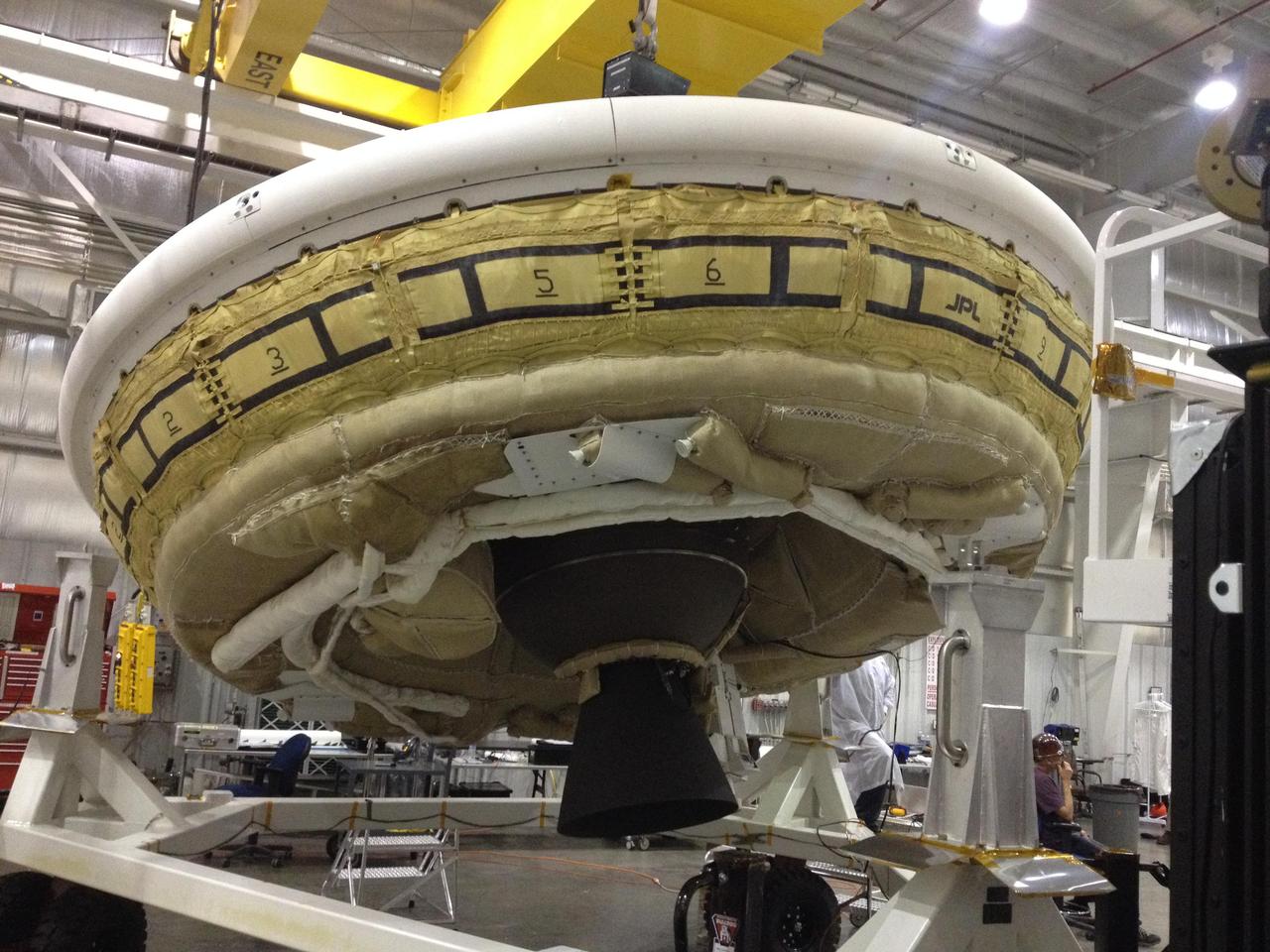
NASA Low-Density Supersonic Decelerator project, will test an inflatable decelerator and a parachute at high altitudes and speeds over the Pacific Missile Range this June.
Bow shocks thought to mark the paths of massive, speeding stars are highlighted in these images from NASA's Spitzer Space Telescope and Wide-field Infrared Survey Explorer, or WISE. Cosmic bow shocks occur when massive stars zip through space, pushing material ahead of them in the same way that water piles up in front of a race boat. The stars also produce high-speed winds that smack into this compressed material. The end result is pile-up of heated material that glows in infrared light. In these images, infrared light has been assigned the colored red. Green shows wispy dust in the region and blue shows stars. The two images at left are from Spitzer, and the one on the right is from WISE. The speeding stars thought to be creating the bow shocks can be seen at the center of each arc-shaped feature. The image at right actually consists of two bow shocks and two speeding stars. All the speeding stars are massive, ranging from about 8 to 30 times the mass of our sun. http://photojournal.jpl.nasa.gov/catalog/PIA20062
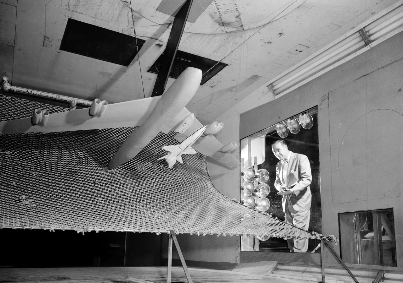
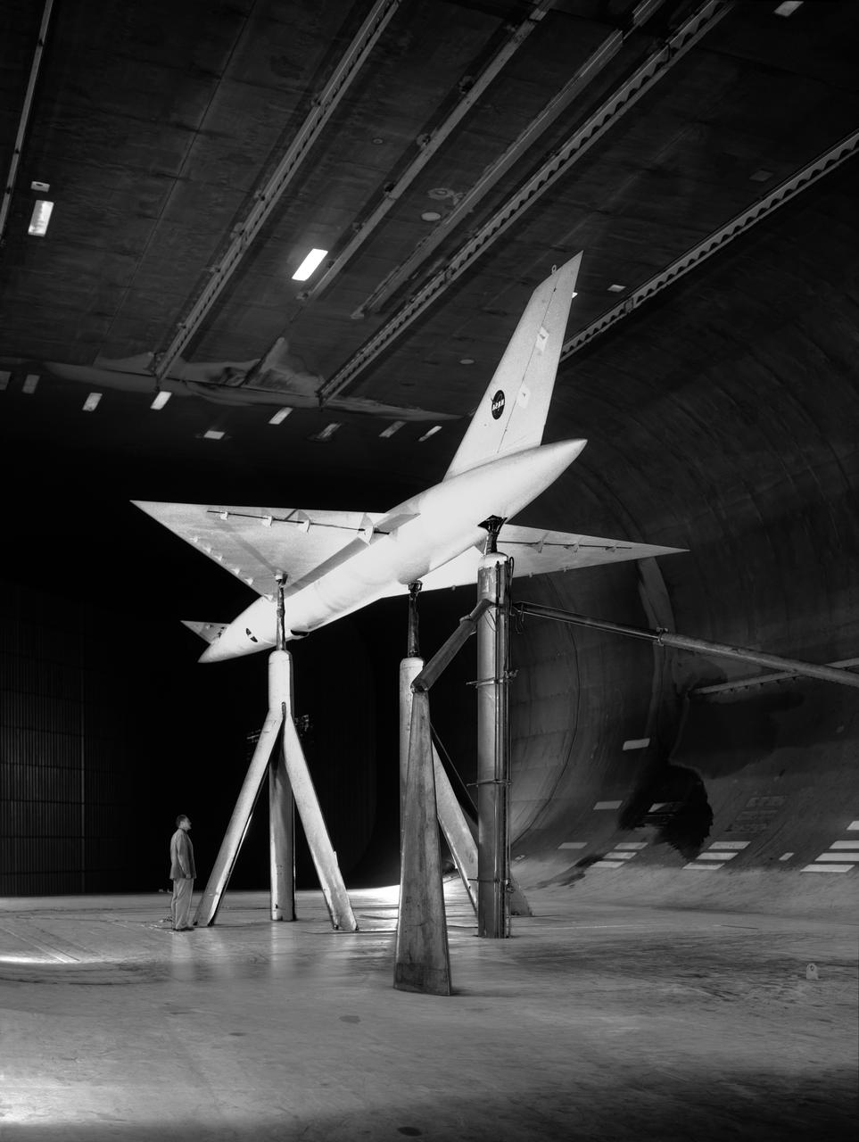
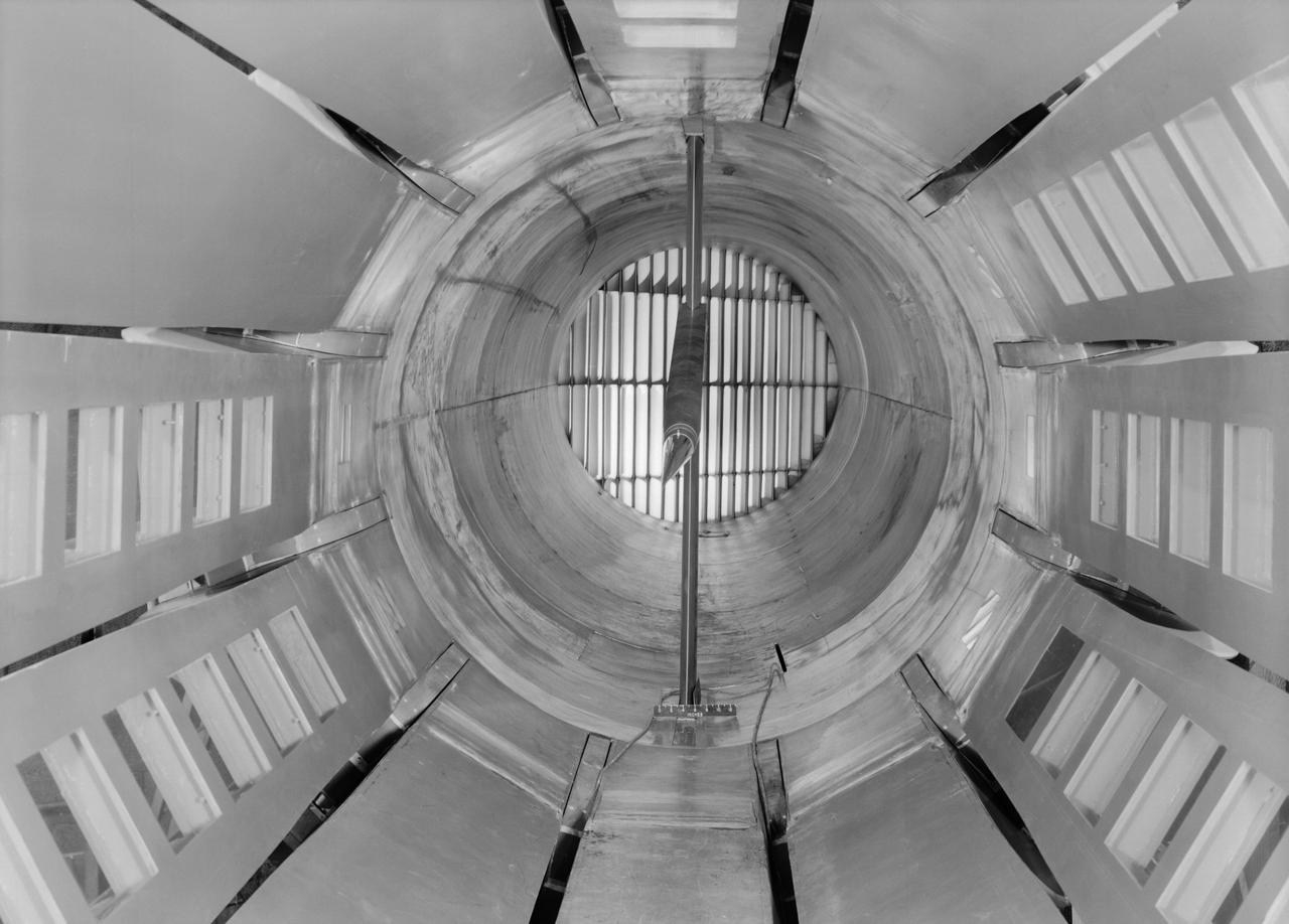
A one-twentieth scale model of the X-15 originally suspended beneath the wing of a B-52 is observed by a scientist of the National Aeronautics and Space Administration (NASA) as it leaves the bomber model in tests to determine the release characteristics and drop motion of the research airplane. Caption: The aerodynamics of air launching the North American X-15 being investigated in the 300MPH Low Speed 7x10 Tunnel, about 1957. Photograph published in Engineer in Charge: A History of the Langley Aeronautical Laboratory, 1917-1958 by James R. Hansen. Page 366. Photograph also published in Sixty Years of Aeronautical Research 1917-1977 By David A. Anderton. A NASA publication. Page 49.
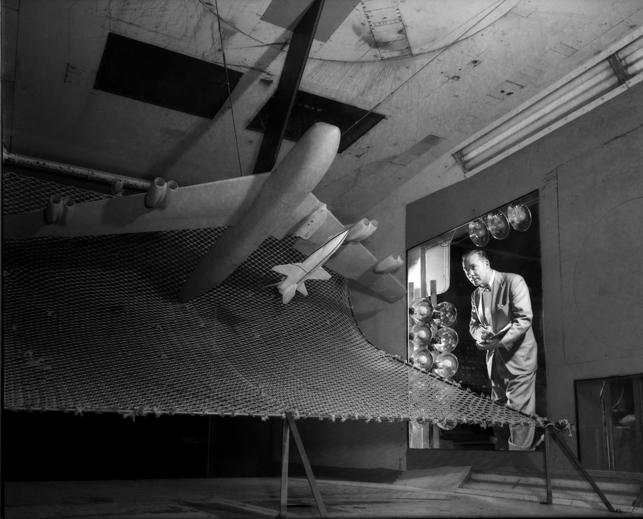
A one-twentieth scale model of the X-15 originally suspended beneath the wing of a B-52 is observed by a scientist of the National Aeronautics and Space Administration (NASA) as it leaves the bomber model in tests to determine the release characteristics and drop motion of the research airplane. Caption: The aerodynamics of air launching the North American X-15 being investigated in the 300MPH Low Speed 7x10 Tunnel, about 1957. Photograph published in Engineer in Charge: A History of the Langley Aeronautical Laboratory, 1917-1958 by James R. Hansen. Page 366. Photograph also published in Sixty Years of Aeronautical Research 1917-1977 By David A. Anderton. A NASA publication. Page 49.
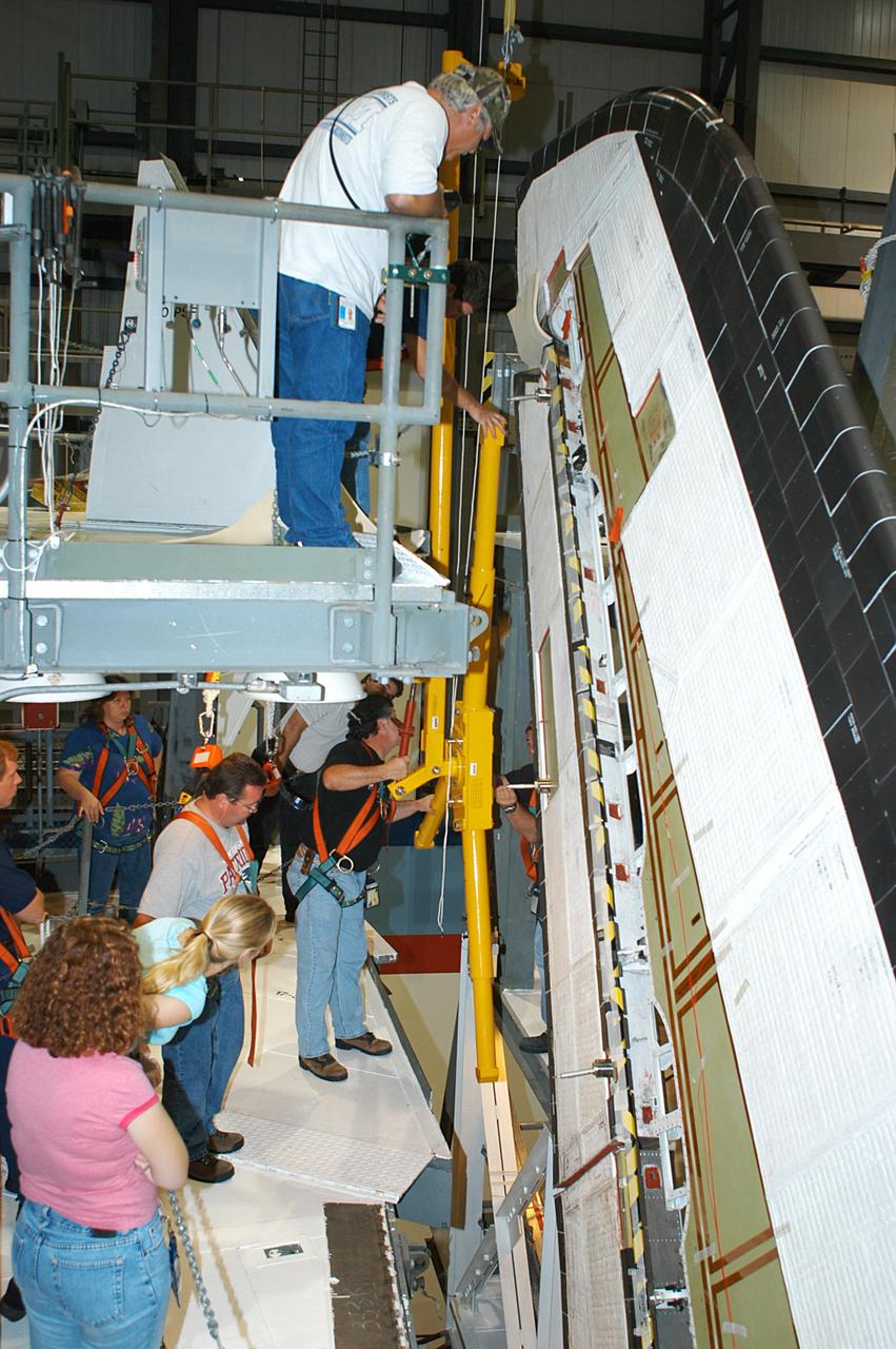
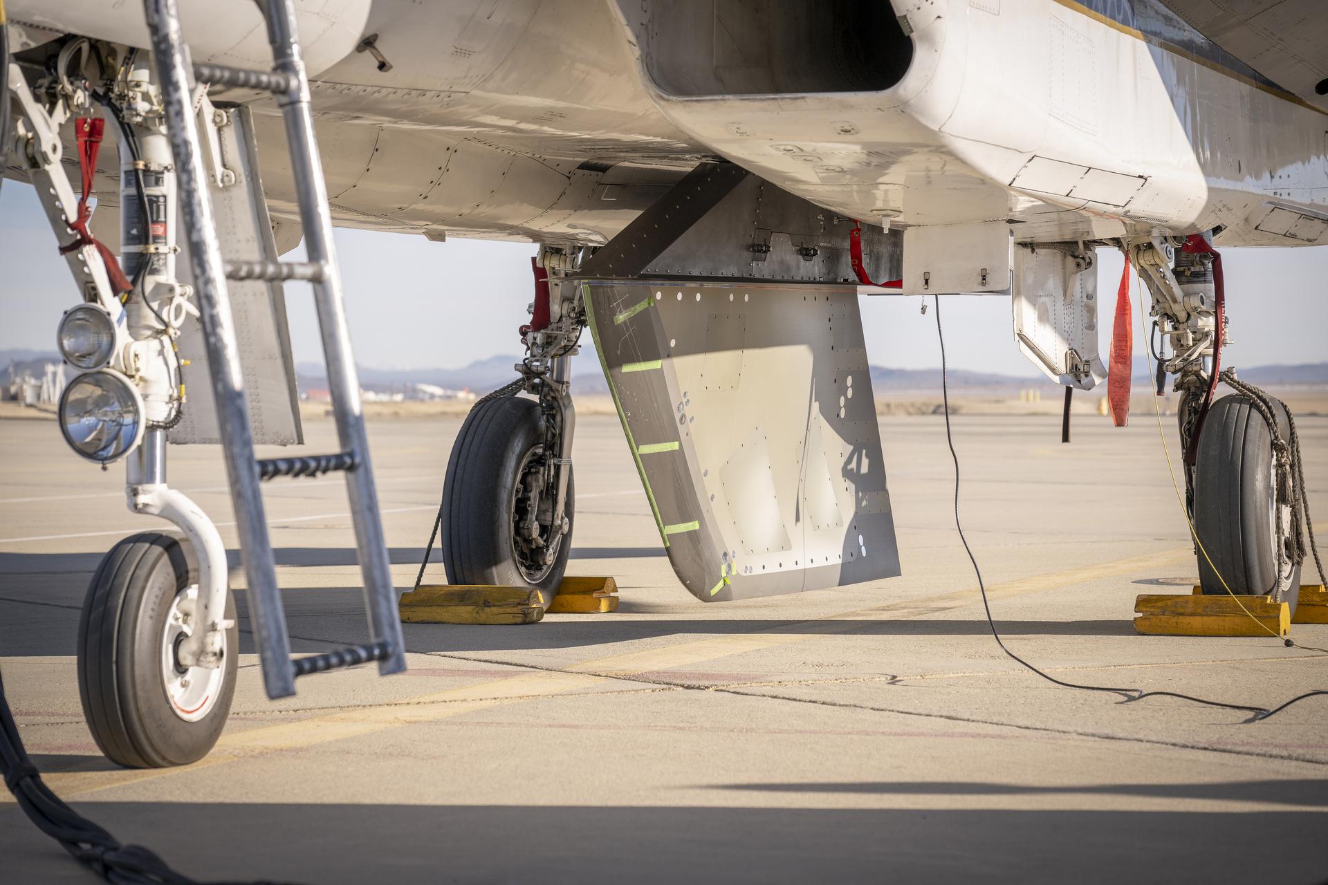
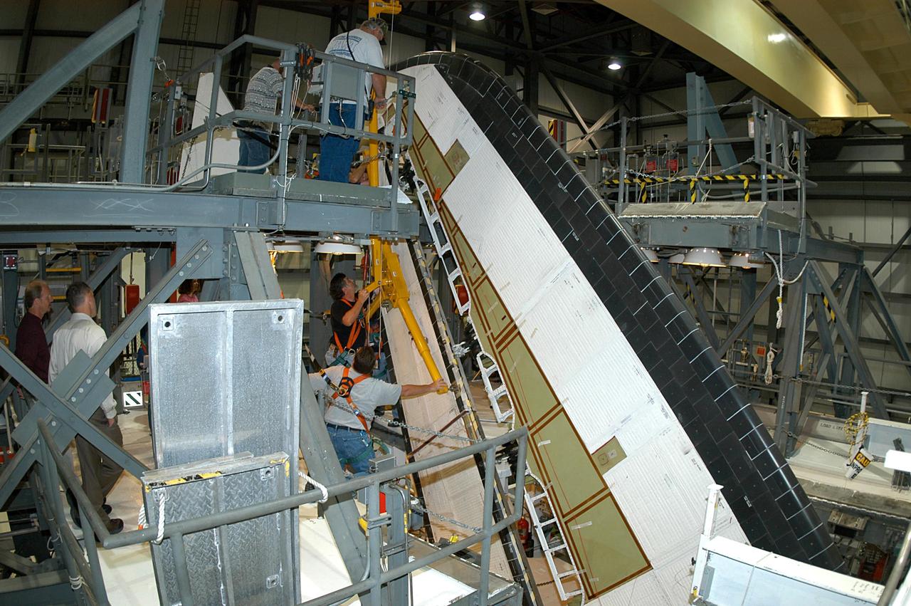
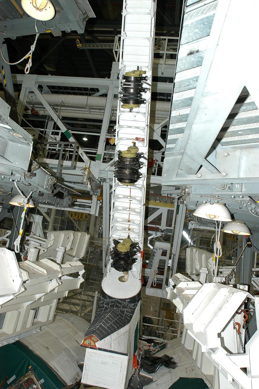
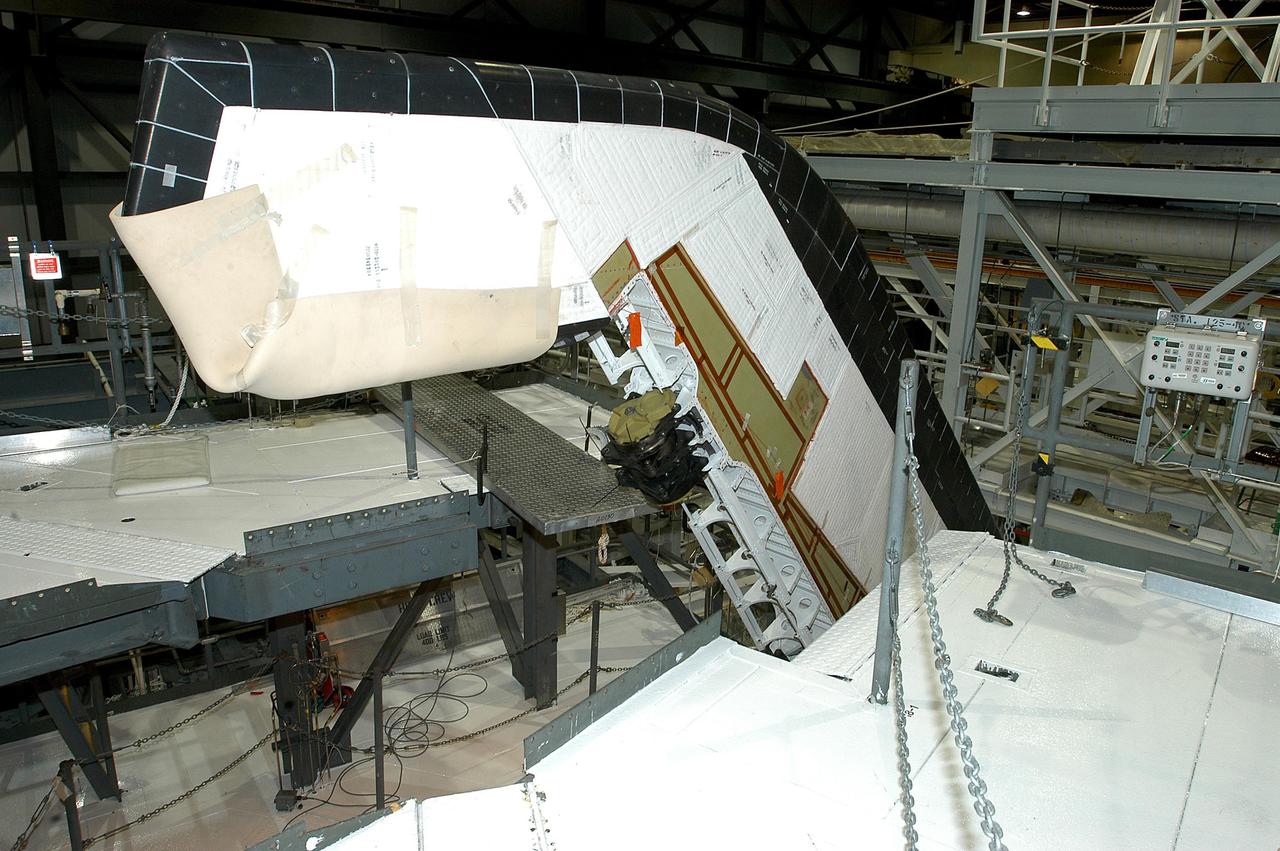
KENNEDY SPACE CENTER, FLA. -- In the Orbiter Processing Facility, a worker (below the upper framework) begins connecting a device to remove the Rudder Speed Brake panel on the vertical tail of orbiter Atlantis. The Rudder Speed Brake is being removed for inspection and maintenance prior to Return to Flight. The vertical tail consists of a structural fin surface made of aluminum, the Rudder Speed Brake surface, a tip and a lower trailing edge. The rudder splits into two halves to serve as a speed brake. The vertical tail and Rudder Speed Brake are covered with a reusable thermal protection system. The Rudder Speed Brake is used to guide and slow the Shuttle as it comes in for a landing.
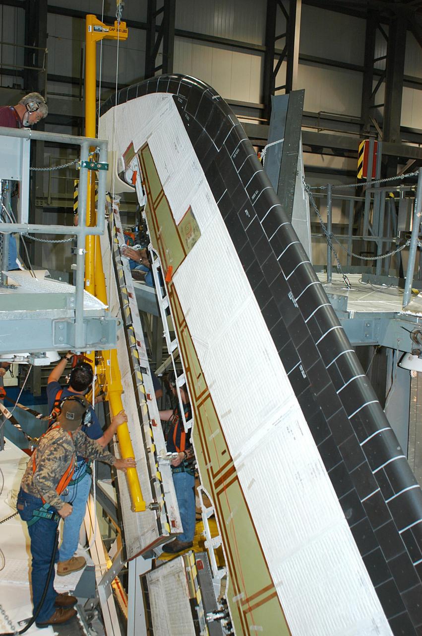
KENNEDY SPACE CENTER, FLA. -- In the Orbiter Processing Facility, workers remove the Rudder Speed Brake panel on the vertical tail of the orbiter Atlantis. The Rudder Speed Brake is being removed for inspection and maintenance prior to Return to Flight. The vertical tail consists of a structural fin surface made of aluminum, the Rudder Speed Brake surface, a tip and a lower trailing edge. The rudder splits into two halves to serve as a speed brake. The vertical tail and Rudder Speed Brake are covered with a reusable thermal protection system. The Rudder Speed Brake is used to guide and slow the Shuttle as it comes in for a landing.
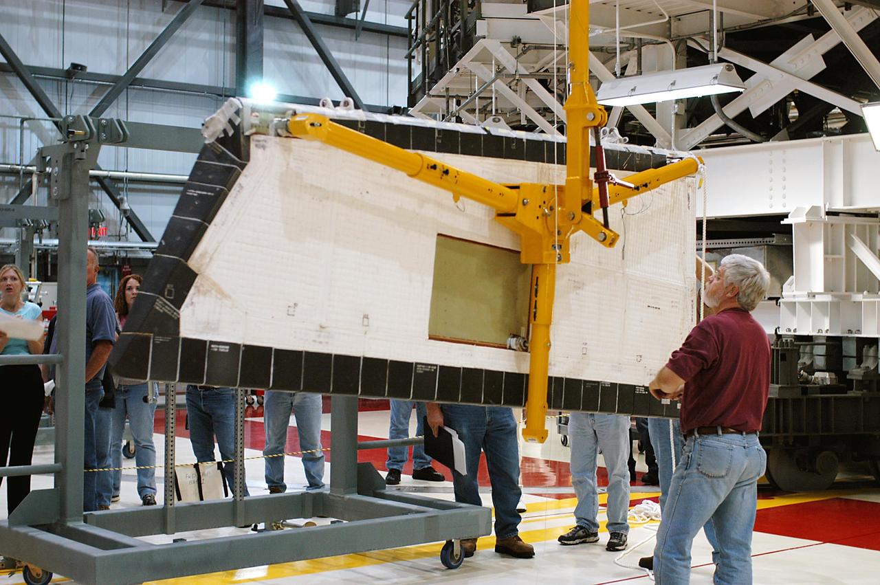
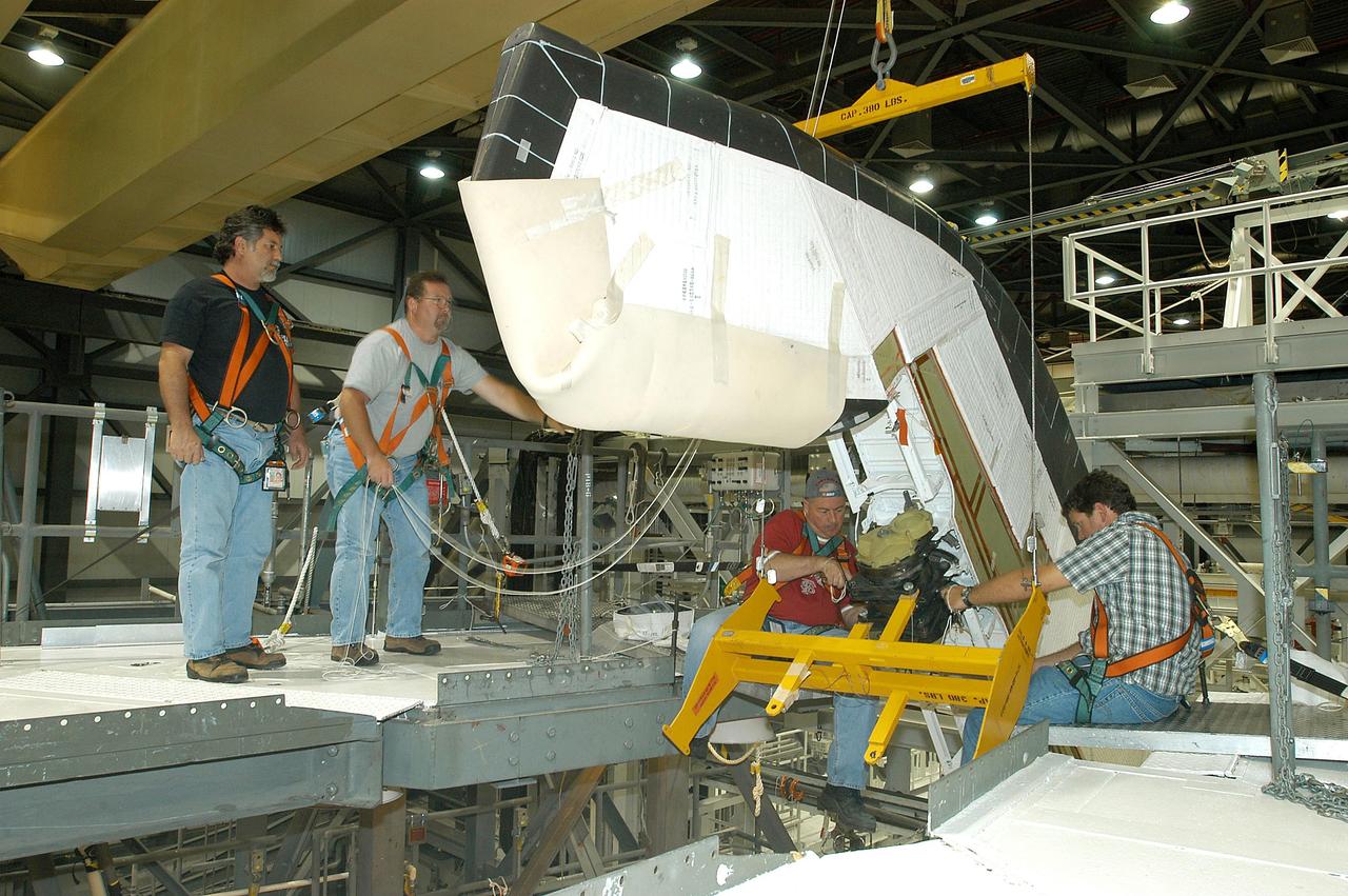
KENNEDY SPACE CENTER, FLA. -- In the Orbiter Processing Facility, workers lower Atlantis’ Rudder Speed Brake panel onto a stand after removing the panel from the vertical tail. The Rudder Speed Brake is being removed for inspection and maintenance prior to Return to Flight. The vertical tail consists of a structural fin surface made of aluminum, the Rudder Speed Brake surface, a tip and a lower trailing edge. The rudder splits into two halves to serve as a speed brake. The vertical tail and Rudder Speed Brake are covered with a reusable thermal protection system. The Rudder Speed Brake is used to guide and slow the Shuttle as it comes in for a landing.
KENNEDY SPACE CENTER, FLA. -- In the Orbiter Processing Facility, the Rudder Speed Brake panel from orbiter Atlantis is lifted clear after being removed. The Rudder Speed Brake is being removed for inspection and maintenance prior to Return to Flight. The vertical tail consists of a structural fin surface made of aluminum, the Rudder Speed Brake surface, a tip and a lower trailing edge. The rudder splits into two halves to serve as a speed brake. The vertical tail and Rudder Speed Brake are covered with a reusable thermal protection system. The Rudder Speed Brake is used to guide and slow the Shuttle as it comes in for a landing.
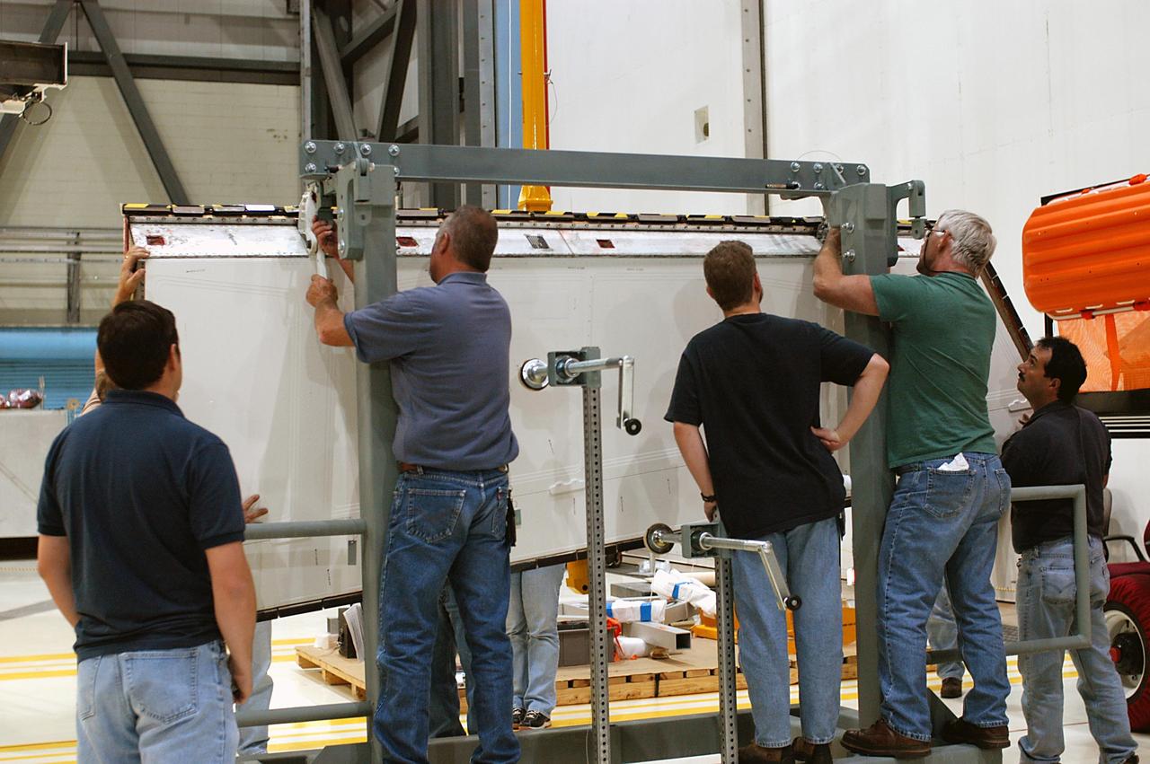
KENNEDY SPACE CENTER, FLA. -- In the Orbiter Processing Facility, workers attach Atlantis’ Rudder Speed Brake panel to a stand after removing the panel from the vertical tail. The Rudder Speed Brake is being removed for inspection and maintenance prior to Return to Flight. The vertical tail consists of a structural fin surface made of aluminum, the Rudder Speed Brake surface, a tip and a lower trailing edge. The rudder splits into two halves to serve as a speed brake. The vertical tail and Rudder Speed Brake are covered with a reusable thermal protection system. The Rudder Speed Brake is used to guide and slow the Shuttle as it comes in for a landing.
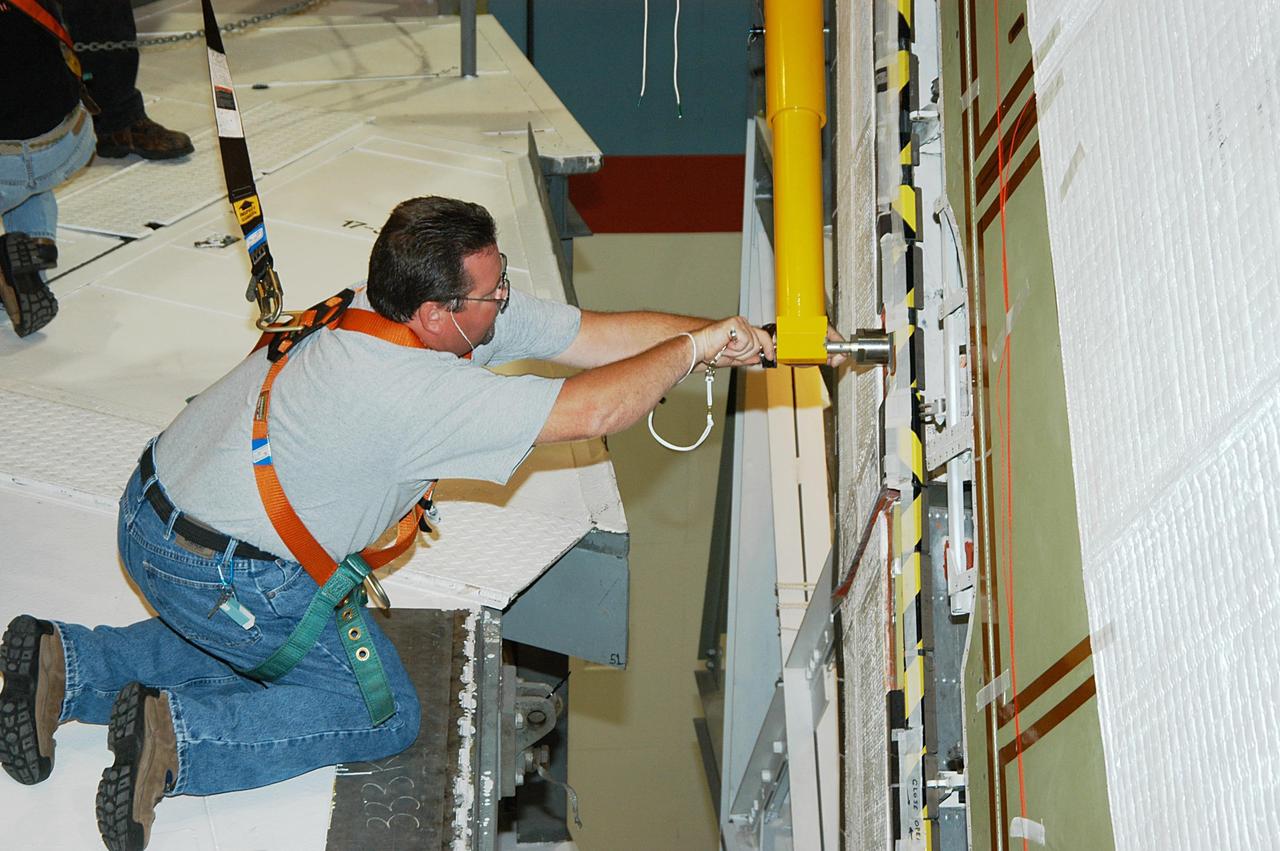
KENNEDY SPACE CENTER, FLA. -- In the Orbiter Processing Facility, a worker tightens a fitting on the device being used to remove the Rudder Speed Brake panel on the vertical tail of the orbiter Atlantis. The Rudder Speed Brake is being removed for inspection and maintenance prior to Return to Flight. The vertical tail consists of a structural fin surface made of aluminum, the Rudder Speed Brake surface, a tip and a lower trailing edge. The rudder splits into two halves to serve as a speed brake. The vertical tail and Rudder Speed Brake are covered with a reusable thermal protection system. The Rudder Speed Brake is used to guide and slow the Shuttle as it comes in for a landing.

KENNEDY SPACE CENTER, FLA. -- In the Orbiter Processing Facility, workers attach Atlantis’ Rudder Speed Brake panel to a stand after removing the panel from the vertical tail. The Rudder Speed Brake is being removed for inspection and maintenance prior to Return to Flight. The vertical tail consists of a structural fin surface made of aluminum, the Rudder Speed Brake surface, a tip and a lower trailing edge. The rudder splits into two halves to serve as a speed brake. The vertical tail and Rudder Speed Brake are covered with a reusable thermal protection system. The Rudder Speed Brake is used to guide and slow the Shuttle as it comes in for a landing.
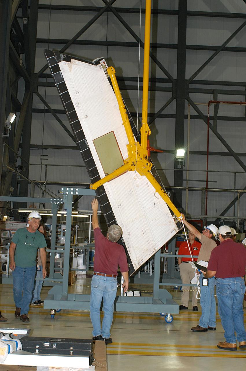
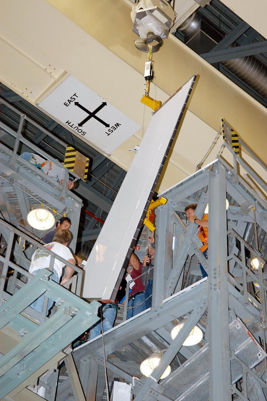
KENNEDY SPACE CENTER, FLA. -- In the Orbiter Processing Facility, workers lower Atlantis’ Rudder Speed Brake panel toward the floor after removing the panel from the vertical tail. The Rudder Speed Brake is being removed for inspection and maintenance prior to Return to Flight. The vertical tail consists of a structural fin surface made of aluminum, the Rudder Speed Brake surface, a tip and a lower trailing edge. The rudder splits into two halves to serve as a speed brake. The vertical tail and Rudder Speed Brake are covered with a reusable thermal protection system. The Rudder Speed Brake is used to guide and slow the Shuttle as it comes in for a landing.
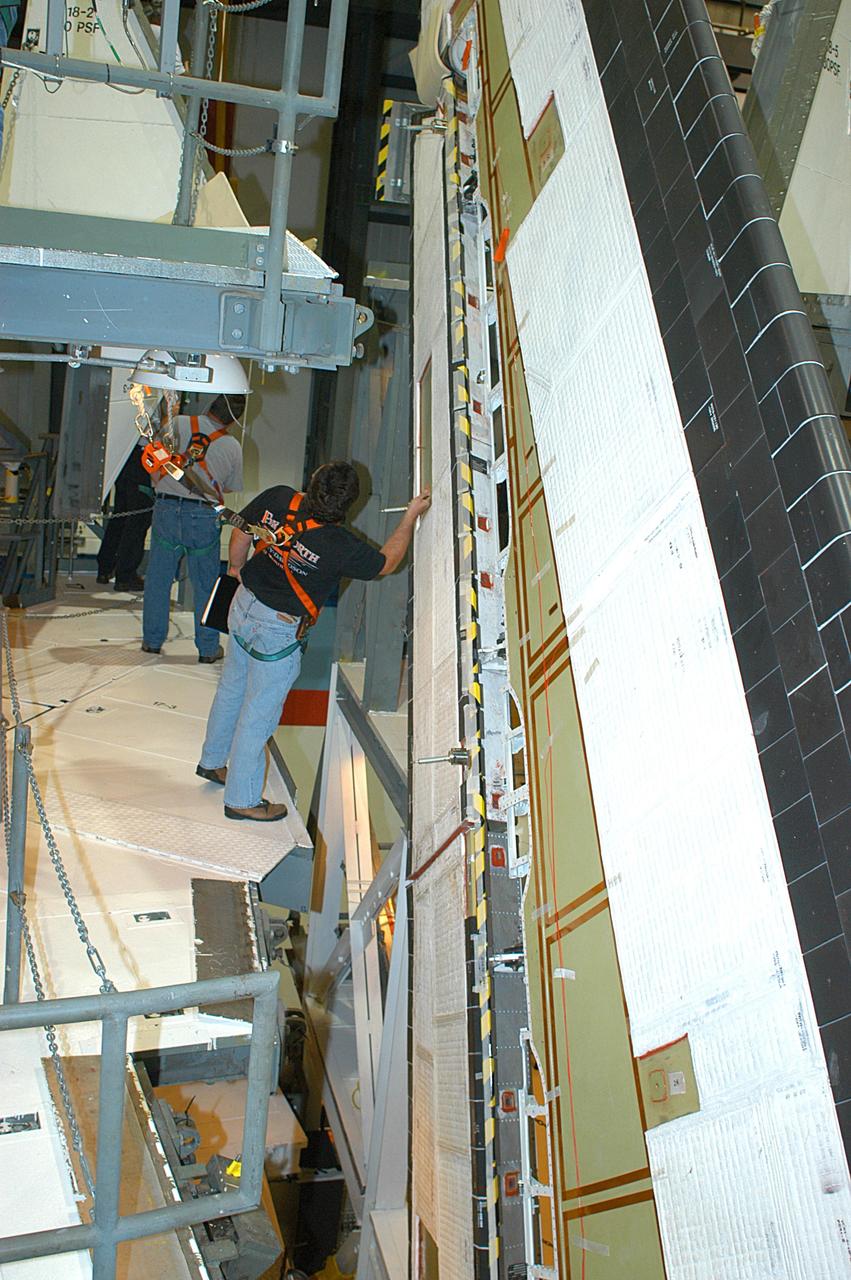
KENNEDY SPACE CENTER, FLA. -- In the Orbiter Processing Facility, a technician looks at the Rudder Speed Brake panel on the vertical tail of orbiter Atlantis. The Rudder Speed Brake is being removed for inspection and maintenance prior to Return to Flight. The vertical tail consists of a structural fin surface made of aluminum, the Rudder Speed Brake surface, a tip and a lower trailing edge. The rudder splits into two halves to serve as a speed brake. The vertical tail and Rudder Speed Brake are covered with a reusable thermal protection system. The Rudder Speed Brake is used to guide and slow the Shuttle as it comes in for a landing.
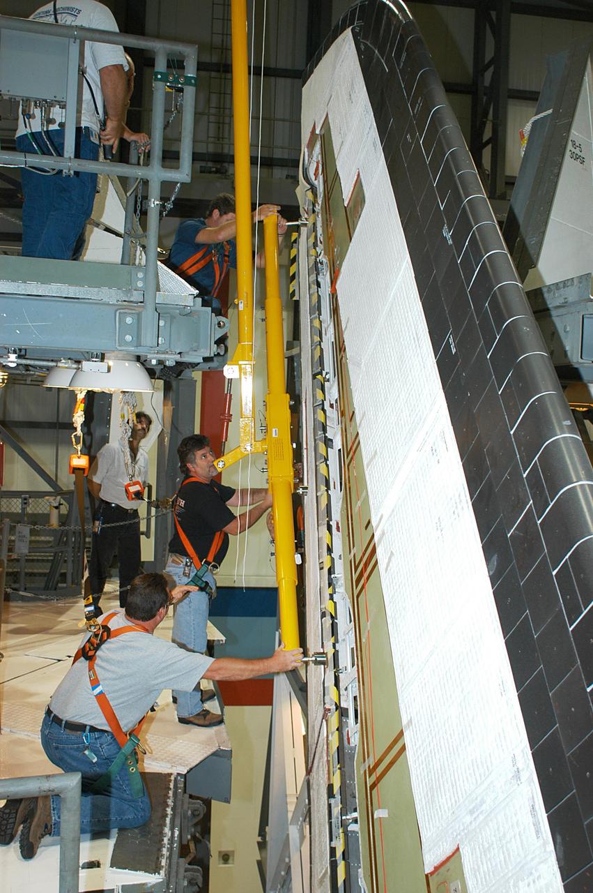
KENNEDY SPACE CENTER, FLA. -- In the Orbiter Processing Facility, workers connect a device onto the vertical tail of the orbiter Atlantis to remove the Rudder Speed Brake panel. The Rudder Speed Brake is being removed for inspection and maintenance prior to Return to Flight. The vertical tail consists of a structural fin surface made of aluminum, the Rudder Speed Brake surface, a tip and a lower trailing edge. The rudder splits into two halves to serve as a speed brake. The vertical tail and Rudder Speed Brake are covered with a reusable thermal protection system. The Rudder Speed Brake is used to guide and slow the Shuttle as it comes in for a landing.
KENNEDY SPACE CENTER, FLA. -- In the Orbiter Processing Facility, workers begin removing the Rudder Speed Brake panel on the vertical tail of the orbiter Atlantis. The Rudder Speed Brake is being removed for inspection and maintenance prior to Return to Flight. The vertical tail consists of a structural fin surface made of aluminum, the Rudder Speed Brake surface, a tip and a lower trailing edge. The rudder splits into two halves to serve as a speed brake. The vertical tail and Rudder Speed Brake are covered with a reusable thermal protection system. The Rudder Speed Brake is used to guide and slow the Shuttle as it comes in for a landing.
ALLISON LOW SPEED NOISE FAN WITH SWEPT / LEANED STATORS IN 9X15 FOOT LOW SPEED WIND TUNNEL
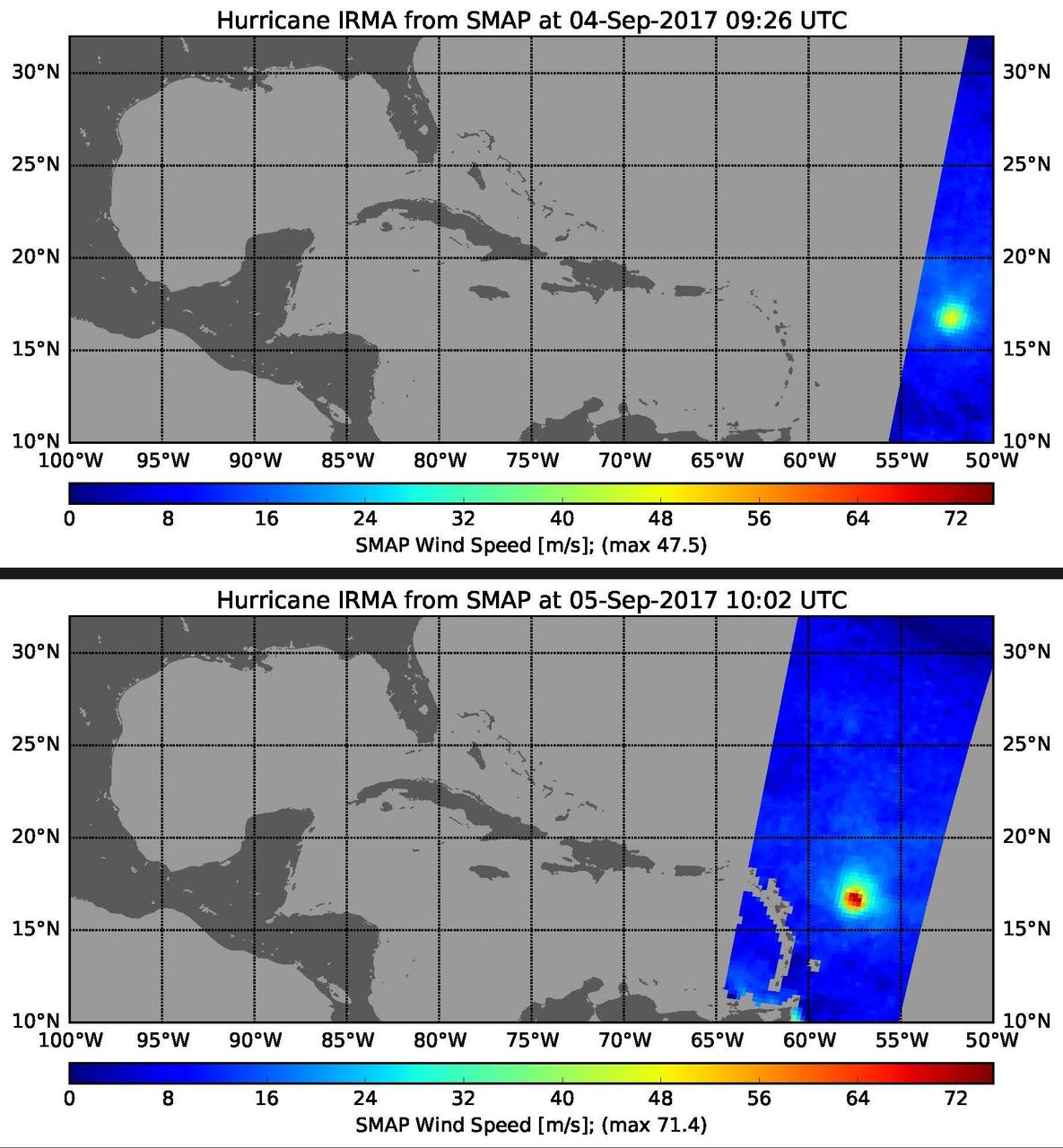
This pair of images shows ocean surface wind speeds for Hurricane Irma as observed at 5:26 a.m. EDT on Sept. 4, 2017 (top) and 24.5 hours later at 6:02 a.m. EDT on September 5th (bottom) by the radiometer instrument on NASA's Soil Moisture Active Passive (SMAP) satellite. Color indicates wind speed, with red being highest and blue lowest. Irma intensified from a Category 2 hurricane on Sept. 4 with observed wind speed of 106 miles per hour (47.5 meters per second) to a Category 5 hurricane on Sept. 5 with a maximum observed wind speed of 160 miles per hour (71.4 meters per second). https://photojournal.jpl.nasa.gov/catalog/PIA21939
Hugh Dryden (far left) presents the NACA Exceptional Service Medal award at the NACA High Speed Flight Station. He awarded (L-R) Joe Walker (X-1A research pilot), Stan Butchart (pilot of the B-29 mothership),and Richard Payne (X-1A crew chief) in recognition of their research extending knowledge of swept wing flight.
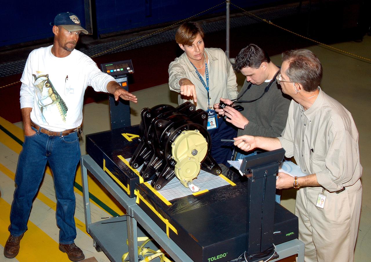
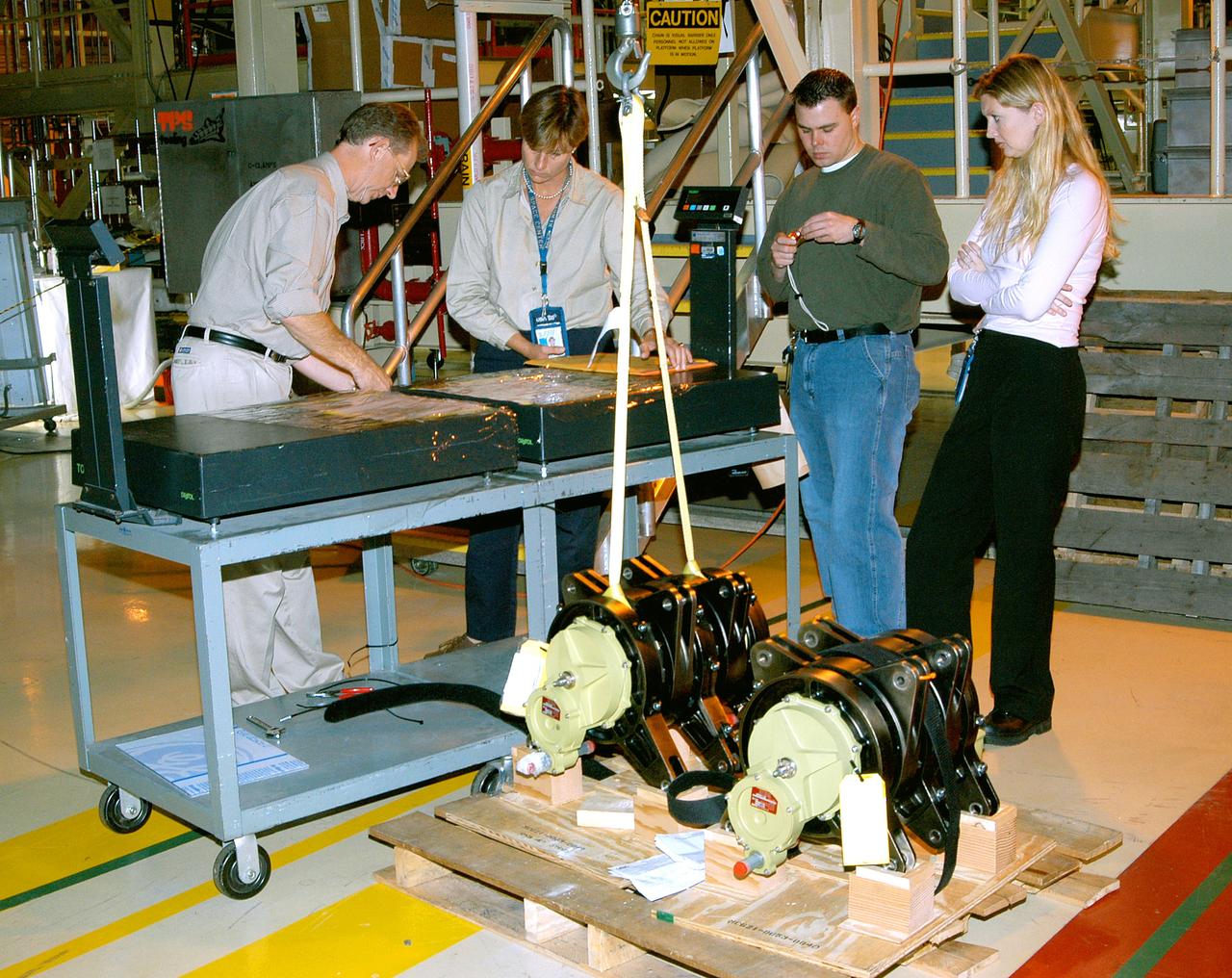
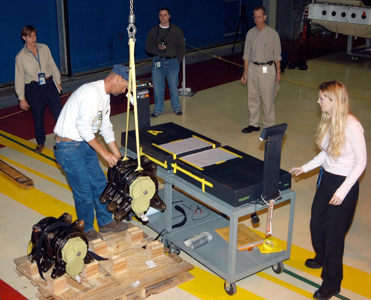
KENNEDY SPACE CENTER, FLA. -- A Rudder Speed Brake Actuator is being removed from the orbiter Atlantis for shipment to the vendor for inspection. An actuator is a motor that moves the tail rudder back and forth to help steer it during landing and brake its speed. The vertical tail consists of a structural fin surface made of aluminum, the Rudder Speed Brake surface, a tip and a lower trailing edge. The rudder splits into two halves to serve as a speed brake. The vertical tail and Rudder Speed Brake are covered with a reusable thermal protection system. Atlantis is undergoing maintenance and inspection in the Orbiter Processing Facility for a future mission.
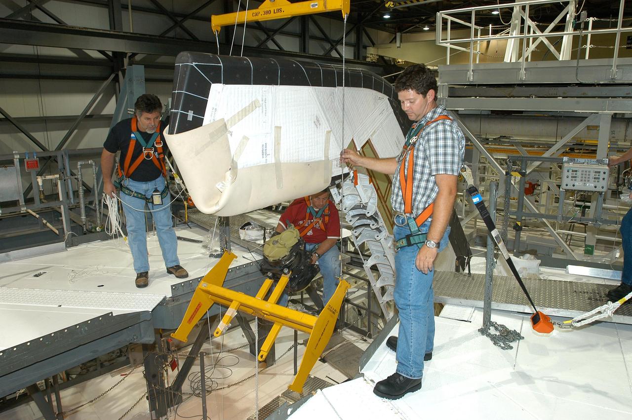
KENNEDY SPACE CENTER, FLA. -- Workers ensure the safe removal of a Rudder Speed Brake Actuator from the orbiter Atlantis. This and three other actuators are being shipped to the vendor for inspection. An actuator is a motor that moves the tail rudder back and forth to help steer it during landing and brake its speed. The vertical tail consists of a structural fin surface made of aluminum, the Rudder Speed Brake surface, a tip and a lower trailing edge. The rudder splits into two halves to serve as a speed brake. The vertical tail and Rudder Speed Brake are covered with a reusable thermal protection system. Atlantis is undergoing maintenance and inspection in the Orbiter Processing Facility for a future mission.
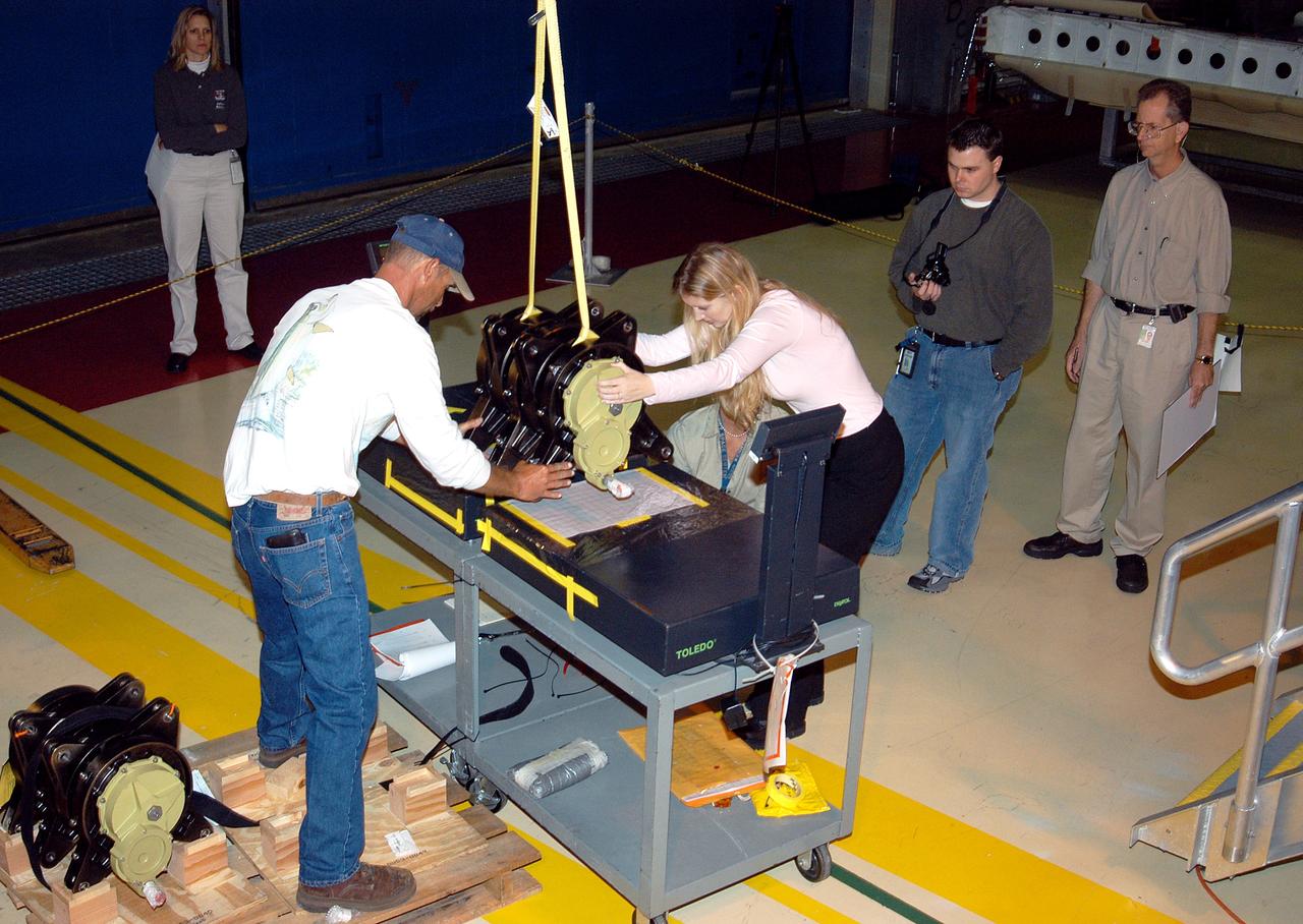
KENNEDY SPACE CENTER, FLA. -- A Rudder Speed Brake Actuator from the orbiter Atlantis is set on a stand on the floor of the Orbiter Processing Facility. This and three other actuators are being shipped to the vendor for inspection. An actuator is a motor that moves the tail rudder back and forth to help steer it during landing and brake its speed. The vertical tail consists of a structural fin surface made of aluminum, the Rudder Speed Brake surface, a tip and a lower trailing edge. The rudder splits into two halves to serve as a speed brake. The vertical tail and Rudder Speed Brake are covered with a reusable thermal protection system. Atlantis is undergoing maintenance and inspection for a future mission.
KENNEDY SPACE CENTER, FLA. -- Workers attach a crane to one of the Rudder Speed Brake Actuators that are being removed from the orbiter Atlantis for shipment to the vendor for inspection. An actuator is a motor that moves the tail rudder back and forth to help steer it during landing and brake its speed. The vertical tail consists of a structural fin surface made of aluminum, the Rudder Speed Brake surface, a tip and a lower trailing edge. The rudder splits into two halves to serve as a speed brake. The vertical tail and Rudder Speed Brake are covered with a reusable thermal protection system. Atlantis is undergoing maintenance and inspection in the Orbiter Processing Facility for a future mission.
KENNEDY SPACE CENTER, FLA. -- A Rudder Speed Brake Actuator is being removed from the orbiter Atlantis for shipment to the vendor for inspection. An actuator is a motor that moves the tail rudder back and forth to help steer it during landing and brake its speed. The vertical tail consists of a structural fin surface made of aluminum, the Rudder Speed Brake surface, a tip and a lower trailing edge. The rudder splits into two halves to serve as a speed brake. The vertical tail and Rudder Speed Brake are covered with a reusable thermal protection system. Atlantis is undergoing maintenance and inspection in the Orbiter Processing Facility for a future mission.
KENNEDY SPACE CENTER, FLA. -- Workers attach a crane to one of the Rudder Speed Brake Actuators that are being removed from the orbiter Atlantis for shipment to the vendor for inspection. An actuator is a motor that moves the tail rudder back and forth to help steer it during landing and brake its speed. The vertical tail consists of a structural fin surface made of aluminum, the Rudder Speed Brake surface, a tip and a lower trailing edge. The rudder splits into two halves to serve as a speed brake. The vertical tail and Rudder Speed Brake are covered with a reusable thermal protection system. Atlantis is undergoing maintenance and inspection in the Orbiter Processing Facility for a future mission.
KENNEDY SPACE CENTER, FLA. -- This is a closeup of one of the Rudder Speed Brake Actuators that are being removed from the orbiter Atlantis for shipment to the vendor for inspection. An actuator is a motor that moves the tail rudder back and forth to help steer it during landing and brake its speed. The vertical tail consists of a structural fin surface made of aluminum, the Rudder Speed Brake surface, a tip and a lower trailing edge. The rudder splits into two halves to serve as a speed brake. The vertical tail and Rudder Speed Brake are covered with a reusable thermal protection system. Atlantis is undergoing maintenance and inspection in the Orbiter Processing Facility for a future mission.
KENNEDY SPACE CENTER, FLA. -- Workers ensure the safe removal of a Rudder Speed Brake Actuator from the orbiter Atlantis. This and three other actuators are being shipped to the vendor for inspection. An actuator is a motor that moves the tail rudder back and forth to help steer it during landing and brake its speed. The vertical tail consists of a structural fin surface made of aluminum, the Rudder Speed Brake surface, a tip and a lower trailing edge. The rudder splits into two halves to serve as a speed brake. The vertical tail and Rudder Speed Brake are covered with a reusable thermal protection system. Atlantis is undergoing maintenance and inspection in the Orbiter Processing Facility for a future mission.
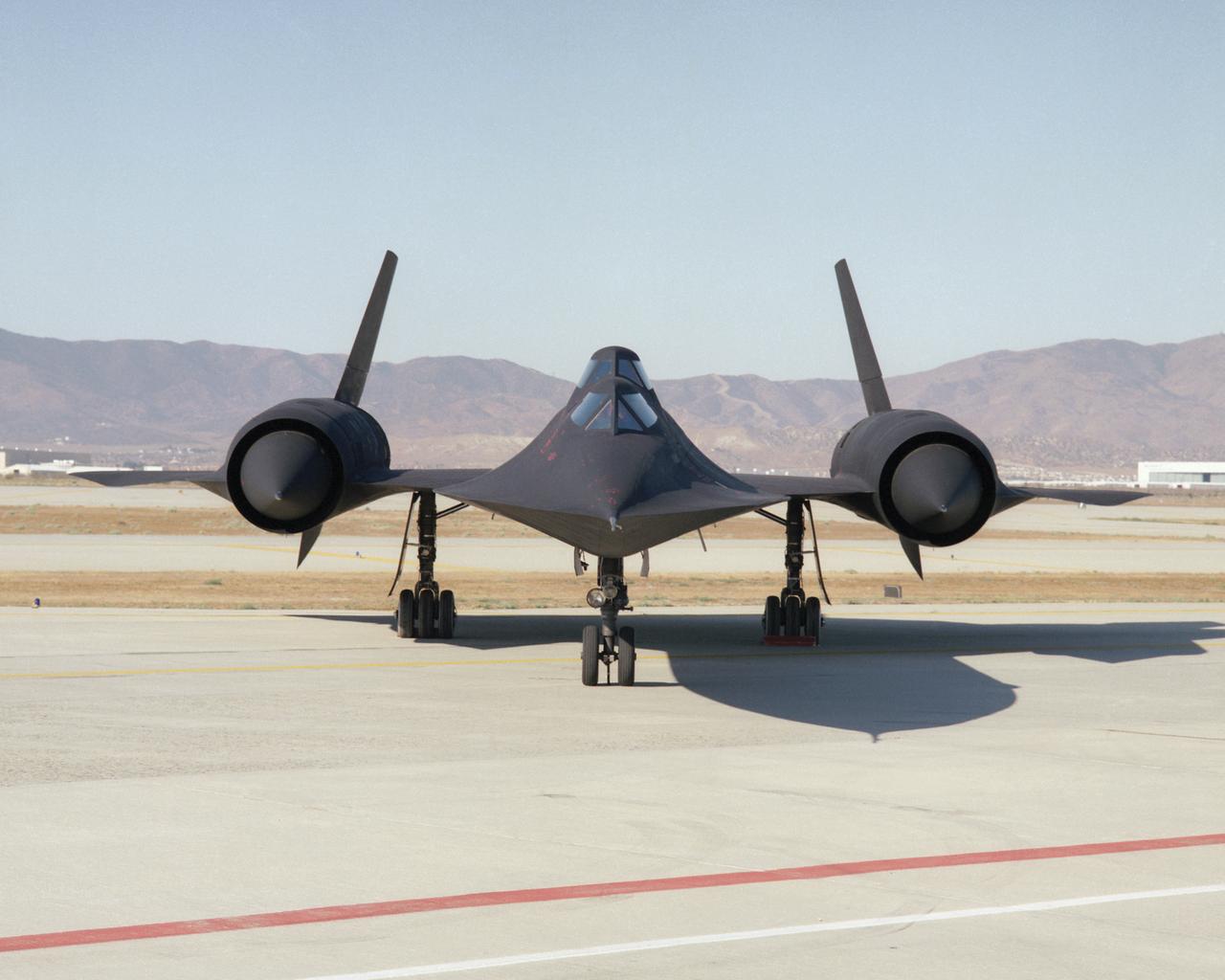
This photo shows a head-on view of NASA's SR-71B, used for pilot proficiency and training, on the ramp at the Air Force's Plant 42 in Palmdale, California, shortly before delivery to the Ames-Dryden Flight Research Facility (later, Dryden Flight Research Center) at Edwards, California. NASA operated two of these unique aircraft, an SR-71A, for high-speed, high altitude research, and this SR- 71B pilot trainer for most of the decade of the 1990s. The "B" model is special because of its raised rear cockpit, which provided a second pilot position so a trainer and an experienced pilot could both see what was going on during flights. The SR-71 was designed and built by the Lockheed Skunk Works, now the Lockheed Martin Skunk Works. Studies have shown that less than 20 percent of the total thrust used to fly at Mach 3 is produced by the basic engine itself. The balance of the total thrust is produced by the unique design of the engine inlet and "moveable spike" system at the front of the engine nacelles, and by the ejector nozzles at the exhaust which burn air compressed in the engine bypass system. Data from the SR-71 high speed research program will be used to aid designers of future supersonic/hypersonic aircraft and propulsion systems, including a high speed civil transport.
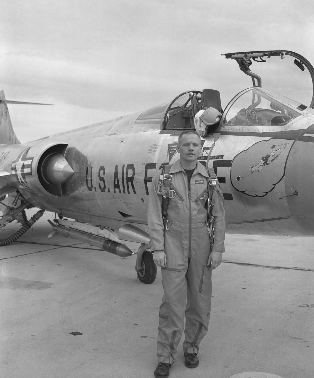
Famed astronaut Neil A. Armstrong – the first person to set foot on the Moon during the historic Apollo 11 mission in July 1969 – spent seven years as a research pilot at the NACA-NASA High-Speed Flight Station, now NASA’s Armstrong Flight Research Center in Edwards, California, before joining the space program. During his time there, he served as a project pilot on the F-100A, F-100C, F-101, and F-104A (pictured here).