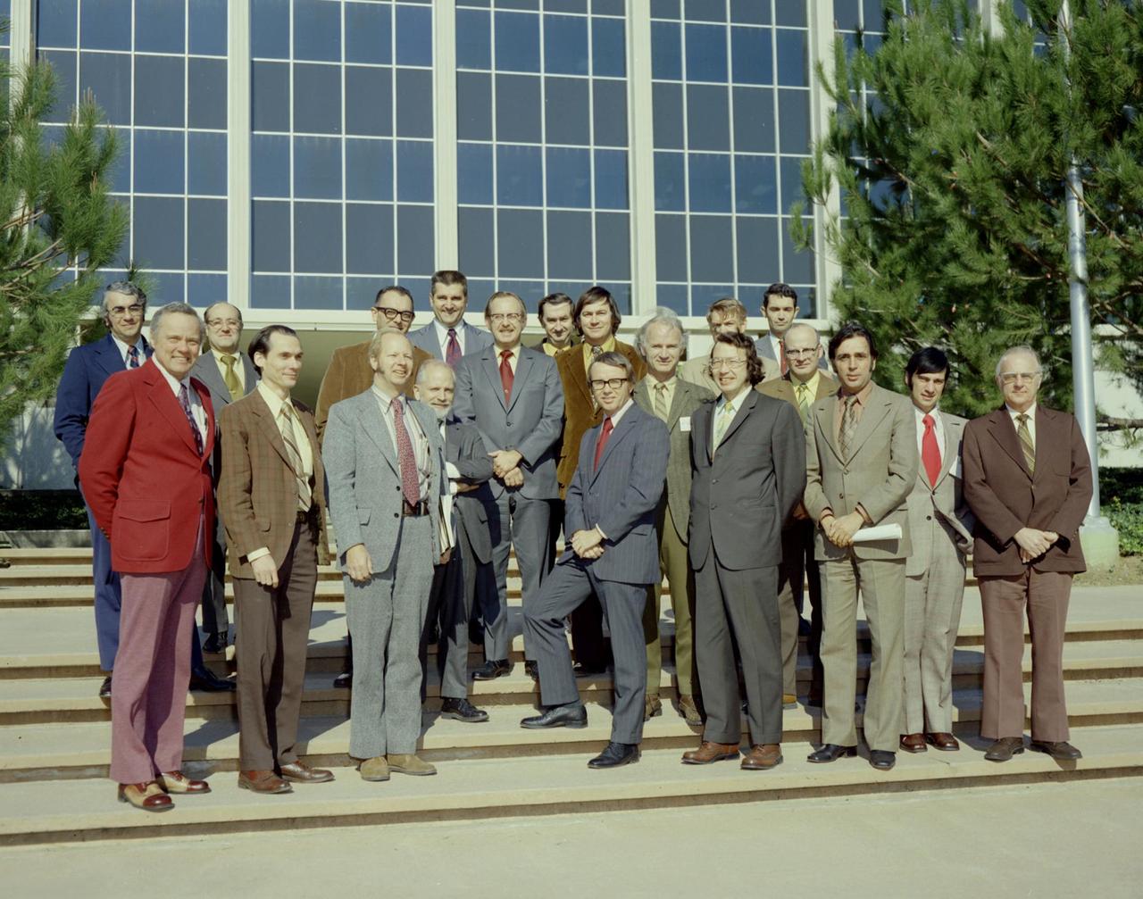
Comparing Notes on Titan -- Radar & Imaging Science Subsystem
Technicians are shown here working on the X-59 fuselage section of the aircraft. The fuselage contains the cockpit and helps define the distinct shape of the X-59.  Lockheed Martin Photography By Garry Tice 1011 Lockheed Way, Palmdale, Ca. 93599 Event: SEG 210 Forebody-Subsystems Date: 5/12/2021
SEG 210 Forebody-Subsystems
Technicians are shown here working on the X-59 fuselage section of the aircraft.  The fuselage contains the cockpit and helps define the distinct shape of the X-59.  Lockheed Martin Photography By Garry Tice 1011 Lockheed Way, Palmdale, Ca. 93599 Event: SEG 210 Forebody-Subsystems Date: 5/12/2021
SEG 210 Forebody-Subsystems
Here is a closer view of the X-59 fuselage section of the aircraft during assembly. The fuselage contains the cockpit and helps define the distinct shape of the X-59.  Lockheed Martin Photography By Garry Tice 1011 Lockheed Way, Palmdale, Ca. 93599 Event: SEG 210 Forebody-Subsystems Date: 5/12/2021
SEG 210 Forebody-Subsystems
Miranda Holton is the Main Propulsion Systems (MPS) Subsystem Manager for NASA’s Commercial Crew Program.   The goal of the Commercial Crew Program is to have safe, reliable and cost-effective access to and from the International Space Station and foster commercial access to other potential low-Earth orbit destinations.
Miranda Holton is the Main Propulsion Systems (MPS) Subsystem Ma
This photograph shows technicians installing the meteoroid shield on the Thruster Attitude Control Subsystem (TACS). At one end of the Orbital Workshop (OWS), the TACS provided short-term control of the attitude of the Skylab.
Skylab
A banner signing event was held April 22, 2019, at NASA’s Kennedy Space Center in Florida, to mark the accomplishments of the Kennedy engineering team that supported the Ground Support Equipment (GSE) Subsystem Software development. This team includes the software leads, local developers, remote developers, modelers, project engineers, software quality assurance, build team members, integrators, system engineers, a chief engineer and some software managers. There are 60 unique instances of GSE Subsystem Software code. As of today, 58 of those 60 instances have completed software Level 5 Verification (L5V) and are in the process of completing Subsystem Verification & Validation.
KSC Engineering Banner Event
A banner signing event was held April 22, 2019, at NASA’s Kennedy Space Center in Florida, to mark the accomplishments of the Kennedy engineering team that supported the Ground Support Equipment (GSE) Subsystem Software development. The team gathered in the observation area of the Operations Support Building II with a view of the Vehicle Assembly Building behind them. This team includes the software leads, local developers, remote developers, modelers, project engineers, software quality assurance, build team members, integrators, system engineers, a chief engineer and some software managers. There are 60 unique instances of GSE Subsystem Software code. As of today, 58 of those 60 instances have completed software Level 5 Verification (L5V) and are in the process of completing Subsystem Verification & Validation.
KSC Engineering Banner Event
This global digital map of Titan was created using data taken by the Cassini spacecraft Imaging Science Subsystem ISS
Map of Titan - December 2006
The face of asteroid Masursky as seen by NASA Cassini Imaging Science Subsystem ISS, January, 2000.
Masursky
Weak but nearly continuous plasma oscillation events — visible as a thin red line in this graphic — connect stronger events in Voyager 1's Plasma Wave Subsystem data.  https://photojournal.jpl.nasa.gov/catalog/PIA24572
Weak and Strong Plasma Oscillation Signals
This image, combining data from the imaging science subsystem and composite infrared spectrometer aboard NASA Cassini spacecraft, shows pockets of heat appearing along one of the mysterious fractures in the south polar region of Saturn moon Enceladus
Enceladus Warm Baghdad Sulcus
With the wheels and suspension system already installed onto one side of NASA Mars rover Curiosity the previous day, spacecraft engineers and technicians prepare the other side mobility subsystem for installation on June 29, 2010.
Installation of Curiosity Wheels and Suspension
This illustration shows the instruments and subsystems of the Sample Analysis at Mars SAM suite on the Curiosity Rover of NASA Mars Science Laboratory Project. SAM analyzes the gases in the Martian atmosphere.
The SAM Suite
This global digital map of Saturn moon Titan was created using images taken by NASA Cassini spacecraft imaging science subsystem ISS. Because of the scattering of light by Titan dense atmosphere, no topographic shading is visible here.
Map of Titan - April 2011
This illustration of NASA's Voyager 2 spacecraft shows the location of the onboard science instruments that are still operating: the magnetometer, the cosmic ray subsystem, the plasma science experiment, the low-energy charged particle instrument and the antennas used by the plasma wave subsystem.  https://photojournal.jpl.nasa.gov/catalog/PIA22915
Voyager 2 Spacecraft Instruments
51F-32-024 (29 July - 6 August 1985) --- Italy's “boot heel" surrounded by waters of the Ionian Sea/Golfo di Taranto and the Adriatic Sea is very clearly visible in this scene made with a handheld 70mm camera. Spacelab 2's versatile instrument pointing system (IPS) protrudes from the cargo bay.
Southern Italy, Instrument Pointing Subsystem
This image shows NASA Cassini spacecraft imaging science subsystem visible-light mosaic of Mimas from previous flybys on the left. The right-hand image shows new infrared temperature data mapped on top of the visible-light image.
Bizarre Temperatures on Mimas
SSC's rocket engine test complex and its four unique test stands provide test operations for the development and certification of propulsion systems, subsystems and components.
Aerial Test Stands
jsc2025e032820 (3/20/2025) --- Left: Astrobee’s guidance, navigation and control  (GNC) subsystem. Components shown in black (Matlab/ROS/C++/Python) indicate a replacement pipeline overriding Astrobee’s default GNC subsystem, outlined in red. Right: software interface between GNC components and Astrobee’s finite state machines (FSMs). The FSM-based nodelets are outlined in blue. Image courtesy of Hector Gutierrez.
PRO Imagery Submittal - SVGS-2
This composite image depicts Jupiter's cloud formations as seen through the eyes of Juno's Microwave Radiometer (MWR) instrument as compared to the top layer, a Cassini Imaging Science Subsystem image of the planet. The MWR can see a couple of hundred miles (kilometers) into Jupiter's atmosphere with its largest antenna. The belts and bands visible on the surface are also visible in modified form in each layer below.   http://photojournal.jpl.nasa.gov/catalog/PIA21107
Juno First Slice of Jupiter
iss068e045306 (Feb. 2, 2023) --- Roscosmos cosmonaut and Expedition 68 Flight Engineer Anna Kikina works on preventive maintenance inside the Zvezda service module's ventilation subsystem aboard the International Space Station.
iss068e045306
Ground crewman at NASA’s Armstrong Flight Research Center in Palmdale, CA install a rail to support the Autonomous, Robotic Telescope Mount Instrument Subsystem, which is part of air-LUSI and has a camera that scans the sky to find the Moon.
Air-LUSI Project - ER-2 Science Mission
An operator dons a Self-Contained Atmospheric Protective Ensemble (SCAPE) suit inside a room in the Multi-Payload Processing Facility (MPPF) at NASA's Kennedy Space Center in Florida on Oct. 31, 2018. SCAPE operators, wearing the suits, will participate in a hypergolic systems hot flow test at the MPPF. The test will serve as operational validation of the hypergol subsystem and demonstrate that the hypergols subsystem can service the Orion spacecraft, flow fuel at the required rates, drain and de-service the system, and meet the intended timeline. SCAPE suite are used in operations involving toxic propellants and are supplied with air either through a hardline or through a self-contained environmental control unit.
SCAPE Suit Up
Self-Contained Atmospheric Protective Ensemble (SCAPE) suits are hanging in a row inside the Multi-Payload Processing Facility (MPPF) at NASA's Kennedy Space Center in Florida on Oct. 31, 2018. SCAPE operators will don the suits and then participate in a hypergolic systems hot flow test at the MPPF. The test will serve as operational validation of the hypergol subsystem and demonstrate that the hypergols subsystem can service the Orion spacecraft, flow fuel at the required rates, drain and de-service the system, and meet the intended timeline. SCAPE suite are used in operations involving toxic propellants and are supplied with air either through a hardline or through a self-contained environmental control unit.
SCAPE Suit Up
An operator dons a Self-Contained Atmospheric Protective Ensemble (SCAPE) suit inside a room in the Multi-Payload Processing Facility (MPPF) at NASA's Kennedy Space Center in Florida on Oct. 31, 2018. SCAPE operators, wearing the suits, will participate in a hypergolic systems hot flow test at the MPPF. The test will serve as operational validation of the hypergol subsystem and demonstrate that the hypergols subsystem can service the Orion spacecraft, flow fuel at the required rates, drain and de-service the system, and meet the intended timeline. SCAPE suite are used in operations involving toxic propellants and are supplied with air either through a hardline or through a self-contained environmental control unit.
SCAPE Suit Up
An operator prepares to don a Self-Contained Atmospheric Protective Ensemble (SCAPE) suit inside a room in the Multi-Payload Processing Facility (MPPF) at NASA's Kennedy Space Center in Florida on Oct. 31, 2018. SCAPE operators, wearing the suits, will participate in a hypergolic systems hot flow test at the MPPF. The test will serve as operational validation of the hypergol subsystem and demonstrate that the hypergols subsystem can service the Orion spacecraft, flow fuel at the required rates, drain and de-service the system, and meet the intended timeline. SCAPE suite are used in operations involving toxic propellants and are supplied with air either through a hardline or through a self-contained environmental control unit.
SCAPE Suit Up
Operators wearing Self-Contained Atmospheric Protective Ensemble (SCAPE) suits depart the suit-up room at the Multi-Payload Processing Facility (MPPF) at NASA's Kennedy Space Center in Florida on Oct. 31, 2018. SCAPE operators are preparing to participate in a hypergolic systems hot flow test at the MPPF. The test will serve as operational validation of the hypergol subsystem and demonstrate that the hypergols subsystem can service the Orion spacecraft, flow fuel at the required rates, drain and de-service the system, and meet the intended timeline. SCAPE suite are used in operations involving toxic propellants and are supplied with air either through a hardline or through a self-contained environmental control unit.
SCAPE Suit Up
Operators wearing Self-Contained Atmospheric Protective Ensemble (SCAPE) suits are inside a transport vehicle near the Multi-Payload Processing Facility (MPPF) at NASA's Kennedy Space Center in Florida on Oct. 31, 2018. SCAPE operators, wearing the suits, will participate in a hypergolic systems hot flow test at the MPPF. The test will serve as operational validation of the hypergol subsystem and demonstrate that the hypergols subsystem can service the Orion spacecraft, flow fuel at the required rates, drain and de-service the system, and meet the intended timeline. SCAPE suite are used in operations involving toxic propellants and are supplied with air either through a hardline or through a self-contained environmental control unit.
SCAPE Suit Up
KENNEDY SPACE CENTER, FLA.  -  In the Orbiter Processing Facility, the processing team celebrates the  successful power-up of the orbiter Discovery.  The vehicle has been undergoing Orbiter Major Modifications in the past year, ranging from wiring, control panels and black boxes to gaseous and fluid systems tubing and components.  These systems were deserviced, disassembled, inspected, modified, reassembled, checked out and reserviced, as were most other systems onboard.  The work includes the installation of the Multifunction Electronic Display Subsystem (MEDS) - a state-of-the-art “glass cockpit.”
KENNEDY SPACE CENTER, FLA. - In the Orbiter Processing Facility, the processing team celebrates the successful power-up of the orbiter Discovery. The vehicle has been undergoing Orbiter Major Modifications in the past year, ranging from wiring, control panels and black boxes to gaseous and fluid systems tubing and components. These systems were deserviced, disassembled, inspected, modified, reassembled, checked out and reserviced, as were most other systems onboard. The work includes the installation of the Multifunction Electronic Display Subsystem (MEDS) - a state-of-the-art “glass cockpit.”
KENNEDY SPACE CENTER, FLA. -  A worker in the Orbiter Processing Facility checks part of the payload bay on Discovery.  The orbiter recently underwent an Orbiter Major Modification period, which included inspection, modifications and reservicing of most systems onboard. The work on Discovery also included the installation of a Multifunction Electronic Display Subsystem (MEDS) - a state-of-the-art “glass cockpit.”  The orbiter is now being prepared for eventual launch on a future mission.
KENNEDY SPACE CENTER, FLA. - A worker in the Orbiter Processing Facility checks part of the payload bay on Discovery. The orbiter recently underwent an Orbiter Major Modification period, which included inspection, modifications and reservicing of most systems onboard. The work on Discovery also included the installation of a Multifunction Electronic Display Subsystem (MEDS) - a state-of-the-art “glass cockpit.” The orbiter is now being prepared for eventual launch on a future mission.
KENNEDY SPACE CENTER, FLA.  -   In the Orbiter Processing Facility, the processing team applaud the successful power-up of the orbiter Discovery.  The vehicle has been undergoing Orbiter Major Modifications in the past year, ranging from wiring, control panels and black boxes to gaseous and fluid systems tubing and components.  These systems were deserviced, disassembled, inspected, modified, reassembled, checked out and reserviced, as were most other systems onboard.  The work includes the installation of the Multifunction Electronic Display Subsystem (MEDS) - a state-of-the-art “glass cockpit.”
KENNEDY SPACE CENTER, FLA. - In the Orbiter Processing Facility, the processing team applaud the successful power-up of the orbiter Discovery. The vehicle has been undergoing Orbiter Major Modifications in the past year, ranging from wiring, control panels and black boxes to gaseous and fluid systems tubing and components. These systems were deserviced, disassembled, inspected, modified, reassembled, checked out and reserviced, as were most other systems onboard. The work includes the installation of the Multifunction Electronic Display Subsystem (MEDS) - a state-of-the-art “glass cockpit.”
KENNEDY SPACE CENTER, FLA. -  Standing on a workstand (at left) in the Orbiter Processing Facility is Stephanie Stilson, NASA vehicle manager for Discovery.  She is being filmed for a special feature on the KSC Web about the recent Orbiter Major Modification period on Discovery, which included inspection, modifications and reservicing of most systems onboard, plus installation of a Multifunction Electronic Display Subsystem (MEDS) - a state-of-the-art “glass cockpit.”  The orbiter is now being prepared for eventual launch on a future mission.
KENNEDY SPACE CENTER, FLA. - Standing on a workstand (at left) in the Orbiter Processing Facility is Stephanie Stilson, NASA vehicle manager for Discovery. She is being filmed for a special feature on the KSC Web about the recent Orbiter Major Modification period on Discovery, which included inspection, modifications and reservicing of most systems onboard, plus installation of a Multifunction Electronic Display Subsystem (MEDS) - a state-of-the-art “glass cockpit.” The orbiter is now being prepared for eventual launch on a future mission.
KENNEDY SPACE CENTER, FLA. -  This is the leading edge of the wing of Discovery, which is in the Orbiter Processing Facility.   The orbiter recently underwent an Orbiter Major Modification period, which included inspection, modifications and reservicing of most systems onboard. The work on Discovery also included the installation of a Multifunction Electronic Display Subsystem (MEDS) - a state-of-the-art “glass cockpit.”  The orbiter is now being prepared for eventual launch on a future mission.
KENNEDY SPACE CENTER, FLA. - This is the leading edge of the wing of Discovery, which is in the Orbiter Processing Facility. The orbiter recently underwent an Orbiter Major Modification period, which included inspection, modifications and reservicing of most systems onboard. The work on Discovery also included the installation of a Multifunction Electronic Display Subsystem (MEDS) - a state-of-the-art “glass cockpit.” The orbiter is now being prepared for eventual launch on a future mission.
KENNEDY SPACE CENTER, FLA. -  Stephanie Stilson, NASA vehicle manager for Discovery, is being filmed for a special feature on the KSC Web about the recent Orbiter Major Modification period, which included inspection, modifications and reservicing of most systems onboard Discovery, plus installation of a Multifunction Electronic Display Subsystem (MEDS) - a state-of-the-art “glass cockpit.”  The orbiter is now being prepared for eventual launch on a future mission.
KENNEDY SPACE CENTER, FLA. - Stephanie Stilson, NASA vehicle manager for Discovery, is being filmed for a special feature on the KSC Web about the recent Orbiter Major Modification period, which included inspection, modifications and reservicing of most systems onboard Discovery, plus installation of a Multifunction Electronic Display Subsystem (MEDS) - a state-of-the-art “glass cockpit.” The orbiter is now being prepared for eventual launch on a future mission.
KENNEDY SPACE CENTER, FLA. -  NASA Vehicle Manager for Discovery, Stephanie Stilson poses for a photo after working with a KSC Web team who were filming a special feature for the KSC Web.  Stilson explained her role in the recent Orbiter Major Modification period, which included inspection, modifications and reservicing of most systems onboard. The work on Discovery also included the installation of a Multifunction Electronic Display Subsystem (MEDS) - a state-of-the-art “glass cockpit.”  The orbiter is now being prepared for eventual launch on a future mission.
KENNEDY SPACE CENTER, FLA. - NASA Vehicle Manager for Discovery, Stephanie Stilson poses for a photo after working with a KSC Web team who were filming a special feature for the KSC Web. Stilson explained her role in the recent Orbiter Major Modification period, which included inspection, modifications and reservicing of most systems onboard. The work on Discovery also included the installation of a Multifunction Electronic Display Subsystem (MEDS) - a state-of-the-art “glass cockpit.” The orbiter is now being prepared for eventual launch on a future mission.
KENNEDY SPACE CENTER, FLA. -  A worker in the Orbiter Processing Facility checks part of the payload bay on Discovery.  The orbiter recently underwent an Orbiter Major Modification period, which included inspection, modifications and reservicing of most systems onboard. The work on Discovery also included the installation of a Multifunction Electronic Display Subsystem (MEDS) - a state-of-the-art “glass cockpit.”  The orbiter is now being prepared for eventual launch on a future mission.
KENNEDY SPACE CENTER, FLA. - A worker in the Orbiter Processing Facility checks part of the payload bay on Discovery. The orbiter recently underwent an Orbiter Major Modification period, which included inspection, modifications and reservicing of most systems onboard. The work on Discovery also included the installation of a Multifunction Electronic Display Subsystem (MEDS) - a state-of-the-art “glass cockpit.” The orbiter is now being prepared for eventual launch on a future mission.
KENNEDY SPACE CENTER, FLA.  -   During power-up of the orbiter Discovery in the Orbiter Processing Facility, a technician turns on a switch.  Discovery has been undergoing Orbiter Major Modifications in the past year, ranging from wiring, control panels and black boxes to gaseous and fluid systems tubing and components.  These systems were deserviced, disassembled, inspected, modified, reassembled, checked out and reserviced, as were most other systems onboard.  The work includes the installation of the Multifunction Electronic Display Subsystem (MEDS) - a state-of-the-art “glass cockpit.”
KENNEDY SPACE CENTER, FLA. - During power-up of the orbiter Discovery in the Orbiter Processing Facility, a technician turns on a switch. Discovery has been undergoing Orbiter Major Modifications in the past year, ranging from wiring, control panels and black boxes to gaseous and fluid systems tubing and components. These systems were deserviced, disassembled, inspected, modified, reassembled, checked out and reserviced, as were most other systems onboard. The work includes the installation of the Multifunction Electronic Display Subsystem (MEDS) - a state-of-the-art “glass cockpit.”
KENNEDY SPACE CENTER, FLA.  -  During power-up of the orbiter Discovery in the Orbiter Processing Facility, a technician moves a switch.  Discovery has been undergoing Orbiter Major Modifications in the past year, ranging from wiring, control panels and black boxes to gaseous and fluid systems tubing and components.  These systems were deserviced, disassembled, inspected, modified, reassembled, checked out and reserviced, as were most other systems onboard.  The work includes the installation of the Multifunction Electronic Display Subsystem (MEDS) - a state-of-the-art “glass cockpit.”
KENNEDY SPACE CENTER, FLA. - During power-up of the orbiter Discovery in the Orbiter Processing Facility, a technician moves a switch. Discovery has been undergoing Orbiter Major Modifications in the past year, ranging from wiring, control panels and black boxes to gaseous and fluid systems tubing and components. These systems were deserviced, disassembled, inspected, modified, reassembled, checked out and reserviced, as were most other systems onboard. The work includes the installation of the Multifunction Electronic Display Subsystem (MEDS) - a state-of-the-art “glass cockpit.”
KENNEDY SPACE CENTER, FLA. -  In the Orbiter Processing Facility, Stephanie Stilson, NASA vehicle manager for Discovery, stands in front of a leading edge on the wing of Discovery.  She is being filmed for a special feature on the KSC Web about the recent Orbiter Major Modification period on Discovery, which included inspection, modifications and reservicing of most systems onboard, plus installation of a Multifunction Electronic Display Subsystem (MEDS) - a state-of-the-art “glass cockpit.”  The orbiter is now being prepared for eventual launch on a future mission.
KENNEDY SPACE CENTER, FLA. - In the Orbiter Processing Facility, Stephanie Stilson, NASA vehicle manager for Discovery, stands in front of a leading edge on the wing of Discovery. She is being filmed for a special feature on the KSC Web about the recent Orbiter Major Modification period on Discovery, which included inspection, modifications and reservicing of most systems onboard, plus installation of a Multifunction Electronic Display Subsystem (MEDS) - a state-of-the-art “glass cockpit.” The orbiter is now being prepared for eventual launch on a future mission.
At the end of 2018, the cosmic ray subsystem (CRS) aboard NASA's Voyager 2 spacecraft provided evidence that Voyager 2 had left the heliosphere (the plasma bubble the Sun blows around itself). There were steep drops in the rate at which particles that originate inside the heliosphere hit the instrument's radiation detector. At the same time, there were significant increases in the rate at which particles that originate outside our heliosphere (also known as galactic cosmic rays) hit the detector.  The graphs show data from Voyager 2's CRS, which averages the number of particle hits over a six-hour block of time. CRS detects both lower-energy particles that originate inside the heliosphere (greater than 0.5 MeV) and higher-energy particles that originate farther out in the galaxy (greater than 70 MeV).   https://photojournal.jpl.nasa.gov/catalog/PIA22924
Voyager 2: Hello Interstellar Space, Goodbye Heliosphere
Steven Grantham (NIST) and John Woodward (NIST) contemplate cable management for air-LUSI’s Irradiance Instrument Subsystem telescope at NASA’s Armstrong Flight Research Center in Palmdale, CA.  It is critical that the delicate fiber optic cables move smoothly with the telescope.
Air-LUSI Project - ER-2 Science Mission
The Orion pressure vessel, which is the underlying structure of the crew module, arrived at the Neil Armstrong Operations and Checkout Building at NASA's Kennedy Space Center in Florida on Feb. 2, 2016. At Kennedy, engineers will outfit the pressure vessel with Orion's systems and subsystems ahead of Artemis I.  Part of Batch image transfer from Flickr.
Orion Pressure Vessel for EM-1 Arrives at Kennedy
ISS020-E-031138 (16 Aug. 2009) --- Cosmonaut Gennady Padalka, Expedition 20 commander, performs a check on the Russian POTOK-150MK (150 micron) air filter unit of the Zvezda Service Module’s SOGS air revitalization subsystem on the International Space Station.
SFOG (Solid Fuel Oxygen Generator) candles in the RS (Russian Segment)
ISS020-E-031128 (16 Aug. 2009) --- Cosmonaut Gennady Padalka, Expedition 20 commander, performs a check on the Russian POTOK-150MK (150 micron) air filter unit of the Zvezda Service Module’s SOGS air revitalization subsystem on the International Space Station.
SFOG (Solid Fuel Oxygen Generator) candles in the RS (Russian Segment)
STS059-58-018 (9-20 April 1994) --- Part of the Space Shuttle Endeavour and its Space Radar Laboratory (SRL-1) payload are backdropped against a colorful display of the Southern Lights (aurora australis). The vehicle was firing a reaction control subsystem thruster (below center) when the 35mm image was exposed.
Endeavour and its SRL-1 payload backdropped against the Southern Lights
Markeeva Morgan, SLS avionics subsystem manager at NASA’s Marshall Space Flight Center, speaks to an audience of Marshall team members April 26 at the Overlook at Redstone. Morgan was the introductory speaker for the luncheon meeting of the Marshall Association, the center’s professional, employee service organization.
April 2017 Marshall Association luncheon with Madison mayor Paul
The instruments that make up the Ames Autonomous Module Scanner (AMS) that provided precise thermal-infrared imaging during the Western States Fire Mission in 2007 are detailed in this photo of the AMS as mounted on Ikhana's pod tray. The large foil-covered foam-insulated box at left covers the pressure vessel containing the data system computers and other electronics. The round white-topped assembly is the scan head, including the scan mirror, folded telescope, blackbody references, spectrometer and detectors. Two pressure boxes visible at the forward end of the tray contain the Applanix POS/AV precision navigation subsystem (black) and the power distributor including circuit breakers and ancillary wiring, scan motor controller and the blackbody reference temperature controller (blue).
ED07-0210-3
S67-49969 (9 Nov. 1967) --- The Apollo 4 (Spacecraft 017/Saturn 501) space mission was launched from Pad A, Launch Complex 39, Kennedy Space Center, Florida. The liftoff of the huge 363-feet tall Apollo/Saturn V space vehicle was at 7:00:01 a.m. (EST), Nov. 9, 1967. The successful objectives of the Apollo 4 Earth-orbital unmanned space mission obtained included (1) flight information on launch vehicle and spacecraft structural integrity and compatibility, flight loads, stage separation, subsystem operation, emergency detection subsystem operation, and (2) evaluation of the Apollo Command Module heat shield under conditions encountered on return from a moon mission.
Apollo 4 liftoff
S67-50903 (9 Nov. 1967) --- The Apollo 4 (Spacecraft 017/Saturn 501) space mission was launched from Pad A, Launch Complex 39, Kennedy Space Center, Florida. The liftoff of the huge 363-feet tall Apollo/Saturn V space vehicle was at 7:00:01 a.m. (EST), Nov. 9, 1967. The successful objectives of the Apollo 4 Earth-orbital unmanned space mission obtained included (1) flight information on launch vehicle and spacecraft structural integrity and compatibility, flight loads, stage separation, subsystem operation, emergency detection subsystem, and (2) evaluation of the Apollo Command Module heat shield under conditions encountered on return from a moon mission.
Apollo 4 launch
KENNEDY SPACE CENTER, FLA.  -  NASA worker Joy Huff (right) shows a leading edge subsystems (LESS) with tile bonded to it to members of the Stafford-Covey Return to Flight Task Group (SCTG).  From left are Dr. Amy Donahue, David Lengyel, Dr. Kathryn Clark,  Richard Covey, former Space Shuttle commander, and William Wegner.  Covey is co-chair of the SCTG along with Thomas P. Stafford, Apollo commander.  Chartered by NASA Administrator Sean O’Keefe, the task group will perform an independent assessment of NASA’s implementation of the final recommendations by the Columbia Accident Investigation Board.
KENNEDY SPACE CENTER, FLA. - NASA worker Joy Huff (right) shows a leading edge subsystems (LESS) with tile bonded to it to members of the Stafford-Covey Return to Flight Task Group (SCTG). From left are Dr. Amy Donahue, David Lengyel, Dr. Kathryn Clark, Richard Covey, former Space Shuttle commander, and William Wegner. Covey is co-chair of the SCTG along with Thomas P. Stafford, Apollo commander. Chartered by NASA Administrator Sean O’Keefe, the task group will perform an independent assessment of NASA’s implementation of the final recommendations by the Columbia Accident Investigation Board.
KENNEDY SPACE CENTER, FLA.  -  During power-up of the orbiter Discovery in the Orbiter Processing Facility, a technician (left) looks at the circuit breaker lights in the cabin.  Discovery has been undergoing Orbiter Major Modifications in the past year, ranging from wiring, control panels and black boxes to gaseous and fluid systems tubing and components.  These systems were deserviced, disassembled, inspected, modified, reassembled, checked out and reserviced, as were most other systems onboard.  The work includes the installation of the Multifunction Electronic Display Subsystem (MEDS) - a state-of-the-art “glass cockpit.”
KENNEDY SPACE CENTER, FLA. - During power-up of the orbiter Discovery in the Orbiter Processing Facility, a technician (left) looks at the circuit breaker lights in the cabin. Discovery has been undergoing Orbiter Major Modifications in the past year, ranging from wiring, control panels and black boxes to gaseous and fluid systems tubing and components. These systems were deserviced, disassembled, inspected, modified, reassembled, checked out and reserviced, as were most other systems onboard. The work includes the installation of the Multifunction Electronic Display Subsystem (MEDS) - a state-of-the-art “glass cockpit.”
KENNEDY SPACE CENTER, FLA.  -   A technician with United Space Alliance works inside orbiter Discovery before power-up of the vehicle in the Orbiter Processing Facility .  Discovery has been undergoing Orbiter Major Modifications in the past year, ranging from wiring, control panels and black boxes to gaseous and fluid systems tubing and components.  These systems were deserviced, disassembled, inspected, modified, reassembled, checked out and reserviced, as were most other systems onboard.  The work includes the installation of the Multifunction Electronic Display Subsystem (MEDS) - a state-of-the-art “glass cockpit.”
KENNEDY SPACE CENTER, FLA. - A technician with United Space Alliance works inside orbiter Discovery before power-up of the vehicle in the Orbiter Processing Facility . Discovery has been undergoing Orbiter Major Modifications in the past year, ranging from wiring, control panels and black boxes to gaseous and fluid systems tubing and components. These systems were deserviced, disassembled, inspected, modified, reassembled, checked out and reserviced, as were most other systems onboard. The work includes the installation of the Multifunction Electronic Display Subsystem (MEDS) - a state-of-the-art “glass cockpit.”
KENNEDY SPACE CENTER, FLA.  -  Shuttle Program Manager Bill Parsons praises the Discovery processing team for their successful power-up of the vehicle after Orbiter Major Modifications (OMM). The OMM work ranged from wiring, control panels and black boxes to gaseous and fluid systems tubing and components.  These systems were deserviced, disassembled, inspected, modified, reassembled, checked out and reserviced, as were most other systems onboard.  The work included the installation of the Multifunction Electronic Display Subsystem (MEDS) - a state-of-the-art “glass cockpit.”
KSC-03pd2467
Engineers celebrate the completion of the Extensible Column Subsystem (XCS) project during a banner event held in Operations Support Building II at Kennedy Space Center. The XCS team successfully executed an aggressive schedule, receiving outstanding support from the fabrication contractor, Met-Con. Full functional testing occurred at Met-Con’s facility, with no mechanical or structural issues. All four columns and the test fixture have been delivered to Kennedy. Full-scale testing will take place when the Mobile Launcher gets to the pad later this summer.
KSC Engineering Banner Event
The Orion crew module for Exploration Mission-1 was moved into the thermal chamber in the Neil Armstrong Operations and Checkout Building high bay at NASA's Kennedy Space Center in Florida. The crew module will undergo a thermal cycle test to assess the workmanship of critical hardware and structural locations. The test also demonstrates crew module subsystem operations in a thermally stressing environment to confirm no damage or anomalous hardware conditions as a result of the test. The Orion spacecraft will launch atop NASA's Space Launch System rocket on its first uncrewed integrated flight.
Orion Crew Module Move
ISS028-E-015647 (10 July 2011) --- This picture of Atlantis' main and subsystem engines is one of a series of images showing various parts of the space shuttle Atlantis in Earth orbit as photographed by one of three crew members -- half the station crew -- who were equipped with still cameras for this purpose on the International Space Station as the shuttle “posed” for photos and visual surveys and performed a back-flip for the rendezvous pitch maneuver (RPM). A 1000 millimeter lens was used to capture this particular series of images.
Mapping Sequence performed during the STS-135 R-Bar Pitch Maneuver
Technicians used a 30-ton crane to lift NASA’s Orion spacecraft on Friday, June 28, 2024, from the Final Assembly and System Testing (FAST) cell to the altitude chamber inside the Neil A. Armstrong Operations and Checkout building at NASA’s Kennedy Space Center in Florida.  The spacecraft, which will be used for the Artemis II mission to orbit the Moon, underwent leak checks and end-to-end performance verification of the vehicle’s subsystems.
Orion Move to Vac Chamber
KENNEDY SPACE CENTER, FLA. --   In Orbiter Processing Facility bay 2, technicians Jesus Rodrigues (left) and James Johnson install a leading edge subsystem carrier panel on the right wing of Endeavour.  The orbiter is scheduled for mission STS-118, targeted for launch on June 28.  The mission will be the 22nd flight to the International Space Station, carrying another starboard array, S5, for installation.  Photo credit: NASA/George Shelton
KSC-07pd0136
Technicians used a 30-ton crane to lift NASA’s Orion spacecraft on Friday, June 28, 2024, from the Final Assembly and System Testing (FAST) cell to the altitude chamber inside the Neil A. Armstrong Operations and Checkout building at NASA’s Kennedy Space Center in Florida.  The spacecraft, which will be used for the Artemis II mission to orbit the Moon, underwent leak checks and end-to-end performance verification of the vehicle’s subsystems.
Orion Move to Vac Chamber
In the Orbiter Processing Facility, Shuttle Program Manager Bill Parsons, center, is briefed on Orbiter Major Modifications (OMM) that were recently completed on Discovery. The OMM work ranged from wiring, control panels and black boxes to gaseous and fluid systems tubing and components. These systems were deserviced, disassembled, inspected, modified, reassembled, checked out and reserviced, as were most other systems onboard. The work included the installation of the Multifunction Electronic Display Subsystem (MEDS) - a state-of-the-art “glass cockpit.”
Bill Parsons with Discovery Processing Team
FROM LEFT, NASA ADMINISTRATOR CHARLES BOLDEN IS JOINED BY PATRICK SCHEUERMANN, NASA MARSHALL SPACE FLIGHT CENTER DIRECTOR; FRANK LEDBETTER, CHIEF OF NONMETALLIC MATERIALS AND MANUFACTURING DIVISION AT THE MARSHALL CENTER; AND ANDY HARDIN, NASA'S SPACE LAUNCH SYSTEM SUBSYSTEM MANAGER FOR LIQUID ENGINES DURING BOLDEN'S TOUR OF THE NATIONAL CENTER FOR ADVANCED MANUFACTURING RAPID PROTOTYPING FACILITY AT THE MARSHALL CENTER ON FRIDAY, FEB. 22.
1300098
Engineers celebrate the completion of the Extensible Column Subsystem (XCS) project during a banner event held in Operations Support Building II at Kennedy Space Center. The XCS team successfully executed an aggressive schedule, receiving outstanding support from the fabrication contractor, Met-Con. Full functional testing occurred at Met-Con’s facility, with no mechanical or structural issues. All four columns and the test fixture have been delivered to Kennedy. Full-scale testing will take place when the Mobile Launcher gets to the pad later this summer.
KSC Engineering Banner Event
In this broad view, the new full-color, flat panel Multifunction Electronic Display Subsystem (MEDS) is shown in the cockpit of the orbiter Atlantis. It is often called the "glass cockpit." The recently installed MEDS upgrade improves crew/orbiter interaction with easy-to-read, graphic portrayals of key flight indicators like attitude display and mach speed. The installation makes Atlantis the most modern orbiter in the fleet and equals the systems on current commercial jet airliners and military aircraft. Atlantis is scheduled to fly on mission STS-101 in early December
KSC-99pp0441
Shuttle Program Manager Bill Parsons praises the Discovery processing team for their successful power-up of the vehicle after Orbiter Major Modifications (OMM). The OMM work ranged from wiring, control panels and black boxes to gaseous and fluid systems tubing and components. These systems were deserviced, disassembled, inspected, modified, reassembled, checked out and reserviced, as were most other systems onboard. The work included the installation of the Multifunction Electronic Display Subsystem (MEDS) - a state-of-the-art “glass cockpit.”
Bill Parsons with Discovery Processing Team
CAPE CANAVERAL, Fla. – In the Operations and Checkout Building at NASA's Kennedy Space Center in Florida, a mock-up of the Orion crew exploration vehicle is on display.  The mock-up details the interior components of the vehicle including seat layout and the subsystem components on the outside of the pressure vessel. Orion mock-ups also have been used to verify accessibility of the servicing locations at the launch pad and in the Vehicle Assembly Building. For information on the development of the Orion capsule, visit www.nasa.gov_orion. Photo credit: NASA_Jim Grossmann
KSC-2010-3132
KENNEDY SPACE CENTER, FLA. --   In Orbiter Processing Facility bay 2, technicians James Johnson (left) and Jesus Rodrigues install a leading edge subsystem carrier panel on the right wing of Endeavour.  The orbiter is scheduled for mission STS-118, targeted for launch on June 28.  The mission will be the 22nd flight to the International Space Station, carrying another starboard array, S5, for installation.  Photo credit: NASA/George Shelton
KSC-07pd0137
CAPE CANAVERAL, Fla. – In the Operations and Checkout Building at NASA's Kennedy Space Center in Florida, Joint Extravehicular NBL ORION Mockup, or JENOM, is on display.  The mock-up details the interior components of the vehicle including seat layout and the subsystem components on the outside of the pressure vessel. Orion mock-ups also have been used to verify accessibility of the servicing locations at the launch pad and in the Vehicle Assembly Building. For information on the development of the Orion capsule, visit www.nasa.gov_orion. Photo credit: NASA_Jim Grossmann
KSC-2010-3134
During power-up of the orbiter Discovery in the Orbiter Processing Facility, a technician moves a circuit reset on the cockpit console. Discovery has been undergoing Orbiter Major Modifications in the past year, ranging from wiring, control panels and black boxes to gaseous and fluid systems tubing and components. These systems were deserviced, disassembled, inspected, modified, reassembled, checked out and reserviced, as were most other systems onboard. The work includes the installation of the Multifunction Electronic Display Subsystem (MEDS) - a state-of-the-art “glass cockpit.”
Discovery Orbiter Major Modifications
The cockpit of the orbiter Atlantis is revealed with its new full-color, flat panel Multifunction Electronic Display Subsystem (MEDS), also called the "glass cockpit." The recently installed MEDS upgrade improves crew/orbiter interaction with easy-to-read, graphic portrayals of key flight indicators like attitude display and mach speed. The installation makes Atlantis the most modern orbiter in the fleet and equals the systems on current commercial jet airliners and military aircraft. Atlantis is scheduled to fly on mission STS-101 in early December
KSC-99pp0439
During power-up of the orbiter Discovery in the Orbiter Processing Facility, a technician adjusts a monitor on the console. Discovery has been undergoing Orbiter Major Modifications in the past year, ranging from wiring, control panels and black boxes to gaseous and fluid systems tubing and components. These systems were deserviced, disassembled, inspected, modified, reassembled, checked out and reserviced, as were most other systems onboard. The work includes the installation of the Multifunction Electronic Display Subsystem (MEDS) - a state-of-the-art “glass cockpit.”
Discovery Orbiter Major Modifications
Engineers celebrate the completion of the Extensible Column Subsystem (XCS) project during a banner event held in Operations Support Building II at Kennedy Space Center. The XCS team successfully executed an aggressive schedule, receiving outstanding support from the fabrication contractor, Met-Con. Full functional testing occurred at Met-Con’s facility, with no mechanical or structural issues. All four columns and the test fixture have been delivered to Kennedy. Full-scale testing will take place when the Mobile Launcher gets to the pad later this summer.
KSC Engineering Banner Event
CAPE CANAVERAL, Fla. – In the Operations and Checkout Building at NASA's Kennedy Space Center in Florida, employees peruse exhibits surrounding a mock-up of the Orion crew exploration vehicle.   The mock-up details the interior components of the vehicle including seat layout and the subsystem components on the outside of the pressure vessel. Orion mock-ups also have been used to verify accessibility of the servicing locations at the launch pad and in the Vehicle Assembly Building. For information on the development of the Orion capsule, visit www.nasa.gov_orion. Photo credit: NASA_Jim Grossmann
KSC-2010-3133
The Orion pressure vessel, which is the underlying structure of the crew module, arrived at the Neil Armstrong Operations and Checkout Building at NASA's Kennedy Space Center in Florida on Feb. 2, 2016 and was maneuvered into a work stand. At Kennedy, engineers will outfit the pressure vessel with Orion's systems and subsystems ahead of Artemis I. The pressure vessel was welded together at the agency's Michoud Assembly Facility in New Orleans. Part of Batch image transfer from Flickr.
Orion pressure vessel for EM-1 arrives at Kennedy
Dan Nolan, who with engineer Lucas Moxey developed the camera system shown in the photo, is seen working with April Torres to prepare it for vibration testing at NASA’s Armstrong Flight Research Center. The camera system is designed to operate as part of the Orion AA-2 test article’s abort test booster/separation ring developmental flight instrumentation subsystem. The testing proved the camera system could function and endure the predicted flight environment.
NASA Armstrong Assists with Orion AA-2 Component Testing
Engineers celebrate the completion of the Extensible Column Subsystem (XCS) project during a banner event held in Operations Support Building II at Kennedy Space Center. The XCS team successfully executed an aggressive schedule, receiving outstanding support from the fabrication contractor, Met-Con. Full functional testing occurred at Met-Con’s facility, with no mechanical or structural issues. All four columns and the test fixture have been delivered to Kennedy. Full-scale testing will take place when the Mobile Launcher gets to the pad later this summer.
KSC Engineering Banner Event
Astronauts Joseph Kerwin (left) and William Lenoir familiarize themselves with equipment aboard the Spacelab mockup during a 1976 visit to the Marshall Space Flight Center. Kerwin and Lenoir were part of an astronaut group briefed on Spacelab subsystems and crew activities by Marshall scientists and engineers. The Marshall Space Flight Center had management responsibility for Spacelab.
Spacelab
In Orbiter Processing Facility bay 2, technicians Jesus Rodrigues (left) and James Johnson install a leading edge subsystem carrier panel on the right wing of Endeavour. The orbiter is scheduled for mission STS-118, targeted for launch on June 28. The mission will be the 22nd flight to the International Space Station, carrying another starboard array, S5, for installation.
Installing a Carrier Panel on Endeavor in OPF 2
On June 16, 2020, a test was conducted at NASA’s Goddard Space Flight Center on a new pointing mode for the observatory. Uploaded to the spacecraft only days before, the mode allows for a problematic gyroscope (a sensor used to determine which direction and how fast Hubble is turning) to be bypassed when trying to keep the spacecraft steady. Systems manager Morgan Van Arsdall monitors the process while many of her teammates monitor the spacecraft’s subsystems from home. Credits: NASA/Goddard/Rebecca Roth
GSFC20200616RR102
Engineers celebrate the completion of the Extensible Column Subsystem (XCS) project during a banner event held in Operations Support Building II at Kennedy Space Center. The XCS team successfully executed an aggressive schedule, receiving outstanding support from the fabrication contractor, Met-Con. Full functional testing occurred at Met-Con’s facility, with no mechanical or structural issues. All four columns and the test fixture have been delivered to Kennedy. Full-scale testing will take place when the Mobile Launcher gets to the pad later this summer.
KSC Engineering Banner Event
Jet Propulsion Laboratory (JPL) technicians clean and  prepare the upper equipment module for mating with the propulsion module subsystem of  the Cassini orbiter in the Payload Hazardous Servicing Facility at KSC in July. A four- year, close-up study of the Saturnian system, the Cassini mission is scheduled for launch  from Cape Canaveral Air Station in October 1997. It will take seven years for the  spacecraft to reach Saturn. Scientific instruments carried aboard the spacecraft will study  Saturn’s atmosphere, magnetic field, rings, and several moons. JPL is managing the  Cassini project for NASA
KSC-97PC1018
Engineers celebrate the completion of the Extensible Column Subsystem (XCS) project during a banner event held in Operations Support Building II at Kennedy Space Center. The XCS team successfully executed an aggressive schedule, receiving outstanding support from the fabrication contractor, Met-Con. Full functional testing occurred at Met-Con’s facility, with no mechanical or structural issues. All four columns and the test fixture have been delivered to Kennedy. Full-scale testing will take place when the Mobile Launcher gets to the pad later this summer.
KSC Engineering Banner Event
This photograph shows an early moment of the first test flight of the Saturn V vehicle for the Apollo 4 mission, photographed by a ground tracking camera, on the morning of November 9, 1967. This mission was the first launch of the Saturn V launch vehicle. Objectives of the unmarned Apollo 4 test flight were to obtain flight information on launch vehicle and spacecraft structural integrity and compatibility, flight loads, stage separation, and subsystems operation including testing of restart of the S-IVB stage, and to evaluate the Apollo command module heat shield.
Saturn Apollo Program
The Apollo Telescope Mount (ATM), designed and developed by the Marshall Space Flight Center, was one of four major components comprising the Skylab (1973-1979). The ATM housed the first manned scientific telescope in space. This photograph is of the ATM thermal systems unit undergoing testing in the Space Environment Simulation Laboratory of the Manned Spacecraft Center (MSC). The ATM thermal systems unit was used to control the temperatures of space instrument's subsystems during a mission. The MSC was renamed the Johnson Space Center (JSC) in early 1973.
n/a
In Orbiter Processing Facility bay 2, technicians James Johnson (left) and Jesus Rodrigues install a leading edge subsystem carrier panel on the right wing of Endeavour. The orbiter is scheduled for mission STS-118, targeted for launch on June 28. The mission will be the 22nd flight to the International Space Station, carrying another starboard array, S5, for installation.
Installing a Carrier Panel on Endeavor in OPF 2
ISS028-E-015588  (10 July 2011) --- This picture of Atlantis' main and subsystem engines is one of a series of images showing various parts of the space shuttle Atlantis in Earth orbit as photographed by one of three crew members -- half the station crew -- who were equipped with still cameras for this purpose on the International Space Station as the shuttle “posed” for photos and visual surveys and performed a back-flip for the rendezvous pitch maneuver (RPM). A  1000 millimeter lens was used to capture this particular series of images.
Mapping Sequence performed during the STS-135 R-Bar Pitch Maneuver
A new full-color, flat panel Multifunction Electronic Display Subsystem (MEDS) is shown in the cockpit of the orbiter Atlantis. It is often called the "glass cockpit." The recently installed MEDS upgrade improves crew/orbiter interaction with easy-to-read, graphic portrayals of key flight indicators like attitude display and mach speed. The installation makes Atlantis the most modern orbiter in the fleet and equals the systems on current commercial jet airliners and military aircraft. Atlantis is scheduled to fly on mission STS-101 in early December
KSC-99pp0440
JSC2024E043924 (4/14/2025) --- The CosmoGirl-Sat CubeSat from Japan Aerospace Exploration Agency (JAXA) shows deep blue solar panels at the front of the spacecraft that power three sunken camera lenses (seen on the top of the satellite), amongst a plethora of other subsystems. CosmoGirl-Sat is developed by the Cosmo Women’s Amateur Radio Club, and its primary mission is to transmit imagery to a ground station on Earth. Image courtesy of Cosmo Girls Amateur Radio Club.
jsc2024e043924
This set of graphs illustrates how data from two key instruments point to NASA's Voyager 2 spacecraft entering interstellar space, or the space between the stars, in November 2018.  The top two plots come from the plasma science experiment (PLS). The plasma -- or ionized gas -- of interstellar space is significantly denser than the plasma inside the bubble of plasma the Sun blows around itself (the heliosphere). There is a jump on the graph in November 2018. At the same time, the measurements show that the outward speed (radial velocity) of the plasma the Sun is blowing (also known as the solar wind) sharply decreased.  The bottom two plots come from the cosmic ray subsystem, which counts hits per second of higher-energy particles that originate from outside the solar bubble and lower-energy particles that originate from inside the solar bubble. The outsideparticles (also known as galactic cosmic rays or GCRs) increased and the inside particles (greater than 0.5 MeV) decreased at the same time the plasma science instrument detected its changes.  The horizontal axis proceeds according to the numbered days of the year in 2018.  https://photojournal.jpl.nasa.gov/catalog/PIA22923
Several Signs Pointing to Interstellar Space
This archival image was released as part of a gallery comparing JPL's past and present, commemorating the 80th anniversary of NASA's Jet Propulsion Laboratory on Oct. 31, 2016.  In December 1972, the science steering group for a mission then-known as Mariner Jupiter Saturn 1977 -- later renamed Voyager -- met for the first time at NASA's Jet Propulsion Laboratory in Pasadena, Calif. They are gathered on the steps in front of the administration building (180).  The mission was so named because it was planning to send Mariner-class spacecraft to Jupiter and Saturn. It was renamed Voyager a few months before the launch of the twin spacecraft in August and September 1977.  This photo shows principal investigators and team leaders for the science experiments and several others from the project and NASA who attended the first meeting. In the first row: Radio Science Subsystem Team Leader Von Eshleman, Project Scientist Edward Stone, Project Manager Harris (Bud) Schurmeier, Mission Analysis and Engineering Manager Ralph Miles, Magnetometer Principal Investigator Norman Ness, NASA Planetary Program Office Deputy Director Ichtiaque Rasool, Robert Soberman (who was proposed to be the principal investigator of the Particulate Matter Investigation, which was not confirmed) and an unidentified member of the NASA Office of Space Science. In the second row: Infrared Interferometer Spectrometer Principal Investigator Rudolf Hanel, Planetary Radio Astronomy Principal Investigator James Warwick, Ultraviolet and Spectrometer Principal Investigator A. Lyle Broadfoot. In the third row: Low-Energy Charged Particles Principal Investigator Stamatios (Tom) Krimigis, Cosmic Ray Subsystem Principal Investigator Rochus (Robbie) Vogt, NASA Outer Planets Missions Program Manager Warren Keller, Imaging Science Subsystem Team Leader Bradford Smith and Photopolarimeter Principal Investigator Charles Lillie. In the fourth row: Plasma Investigation Principal Investigator Herbert Bridge, Spacecraft Systems Manager Raymond Heacock, NASA Outer Planets Missions Program Scientist Milton (Mike) Mitz and Science Manager James Long.  http://photojournal.jpl.nasa.gov/catalog/PIA21122
Voyager First Science Meeting
CAPE CANAVERAL, Fla. - The Orion crew module is lowered onto a workstand in the Operations and Checkout Building high bay at NASA's Kennedy Space Center in Florida.     Slated for Exploration Flight Test-1, an uncrewed mission planned for 2014, the capsule will travel farther into space than any human spacecraft has gone in more than 40 years. NASA's Michoud Assembly Facility in New Orleans built the crew module pressure vessel. The Orion production team will prepare the module for flight by installing heat-shielding thermal protection systems, avionics and other subsystems. For more information, visit http://www.nasa.gov/orion. Photo credit: NASA/Gianni Woods
KSC-2012-3600
KENNEDY SPACE CENTER, Fla. -- Expedition Three Commander Frank Culbertson shows his eagerness for liftoff while suiting up in his launch and entry suit. On mission STS-105, Discovery will be transporting the Expedition Three crew and several scientific experiments and payloads to the International Space Station, including the Early Ammonia Servicer (EAS) tank. The EAS, which will support the thermal control subsystems until a permanent system is activated, will be attached to the Station during two spacewalks. The three-member Expedition Two crew will be returning to Earth aboard Discovery after a five-month stay on the Station. Launch is scheduled for 5:38 p.m. EDT Aug. 9
KSC-01pp1445
Deborah Efua Adu Essumang, system lead scientist, conducts testing of the Volatile Monitoring Oxygen Measurement Subsystem (VMOMS) for Molten Regolith Electrolysis (MRE) inside a laboratory in the Neil A. Armstrong Operations and Checkout Building at NASA’s Kennedy Space Center in Florida on April 19, 2024. The high-temperature electrolytic process aims to extract oxygen from simulated lunar regolith which will be critical to the agency’s Artemis campaign. Oxygen extracted from the Moon can be utilized for propellent to NASA’s lunar landers, breathable oxygen for astronauts, and a variety of other industrial and scientific applications for NASA’s future missions to the Moon.
Molten Regolith Electrolysis Project Testing
KENNEDY SPACE CENTER, FLA. - During a Crew Equipment Interface Test, STS-112 Mission Specialist Piers Sellers looks at the engine on Atlantis, the designated orbiter for the mission. On the 15th assembly flight to the International Space Station, Atlantis and crew will be ferrying the S1 Integrated Truss Structure. The S1 truss is the first starboard (right-side) truss segment, whose main job is providing structural support for the radiator panels that cool the Space Station's complex power system. The S1 truss segment also will house communications systems, external experiment positions and other subsystems.  The S1 truss will be attached to the S0 truss.  STS-112 is currently scheduled for launch Aug. 22, 2002
KSC-02pd1058
This is a view of the the first test flight of the Saturn V vehicle (SA-501) at the Kennedy Space Center (KSC) launch complex 39A, awaiting the scheduled launch on November 9, 1967. Designated as Apollo 4, this mission was the first launch of the Saturn V launch vehicle. Objectives of the unmanned Apollo 4 test flight were to obtain flight information on launch vehicle and spacecraft structural integrity and compatibility, flight loads, stage separation, and subsystems operation including testing of restart of the S-IVB stage, and to evaluate the Apollo command module heat shield.
Saturn Apollo Program