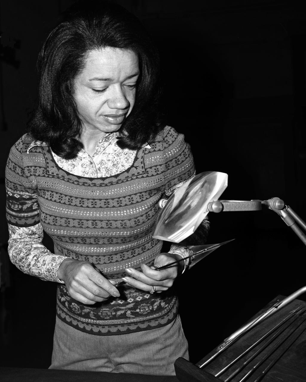
Environmental Portrait of Christine M. Darden. Supersonic Aerodynamics Branch.
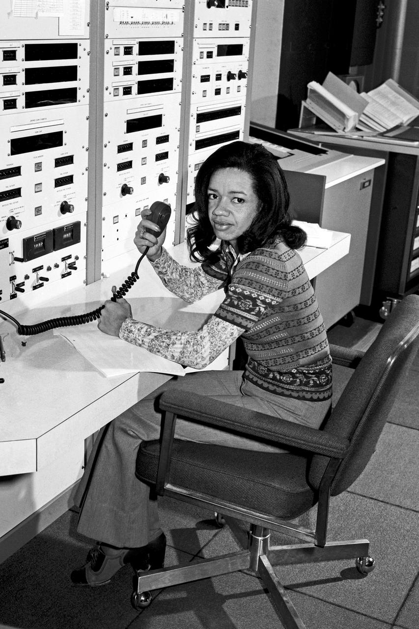
Environmental Portrait of Christine M. Darden. Supersonic Aerodynamics Branch
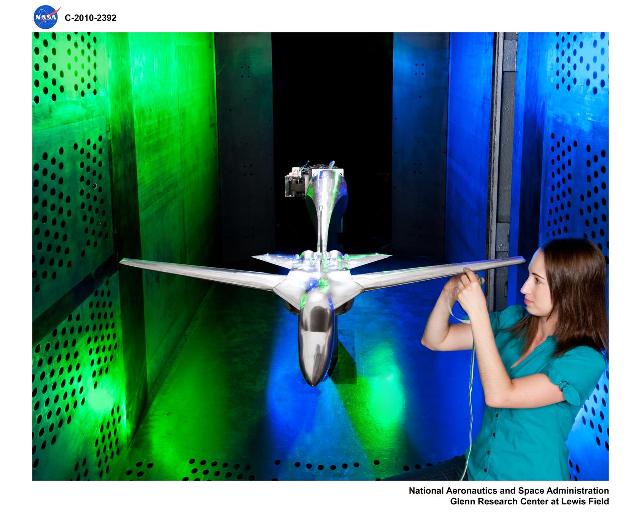
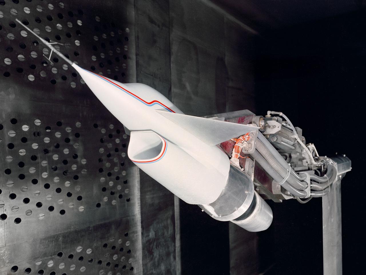
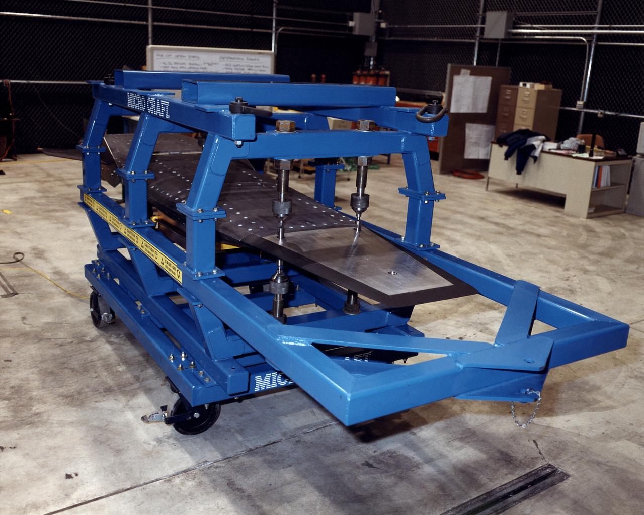
Facility Aerodynamic Validation and Operational Research (FAVOR) aircraft model hardware in 8x6 Supersonic Wind Tunnel (SWT)
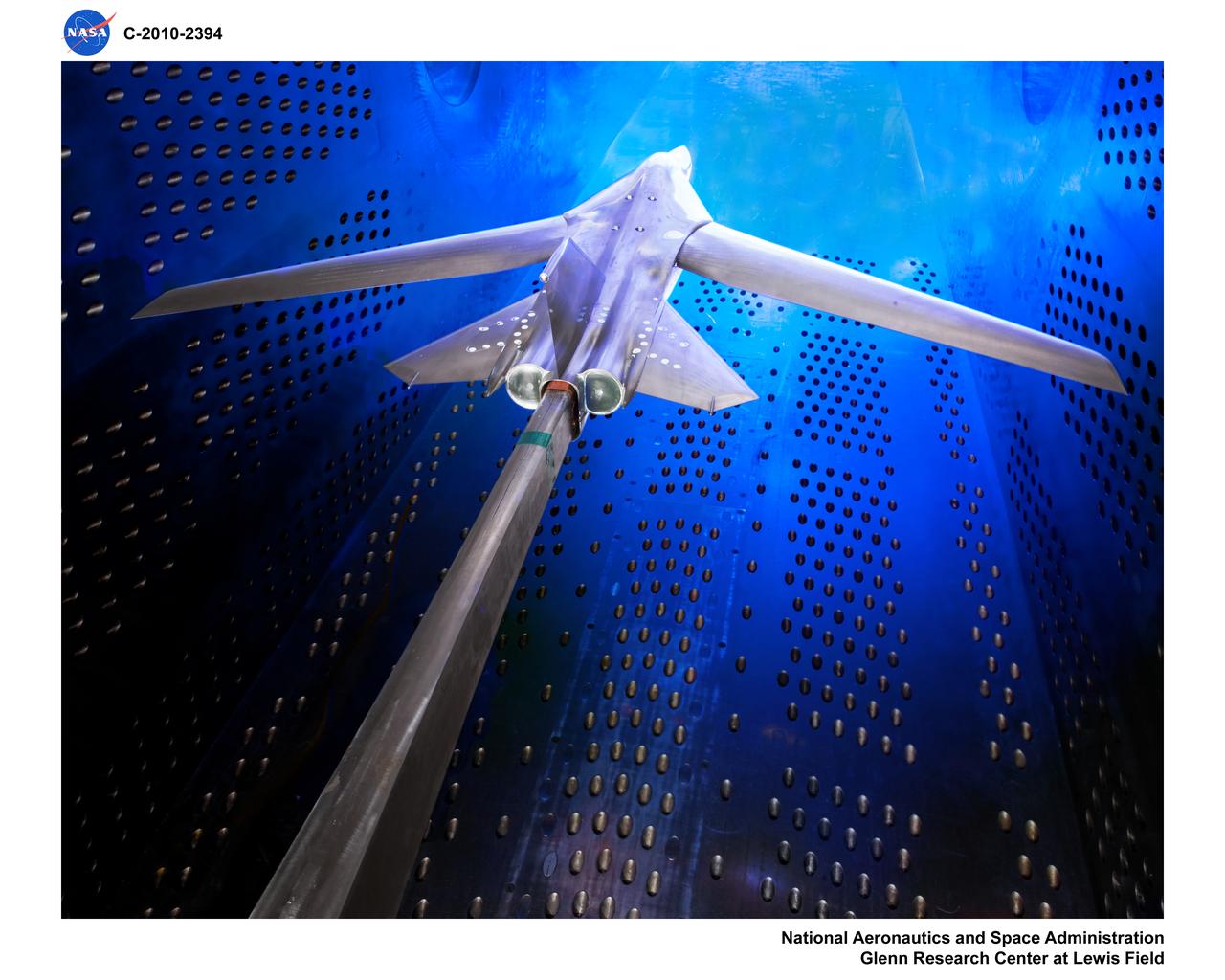
Facility Aerodynamic Validation and Operational Research (FAVOR) aircraft model hardware in 8x6 Supersonic Wind Tunnel (SWT)
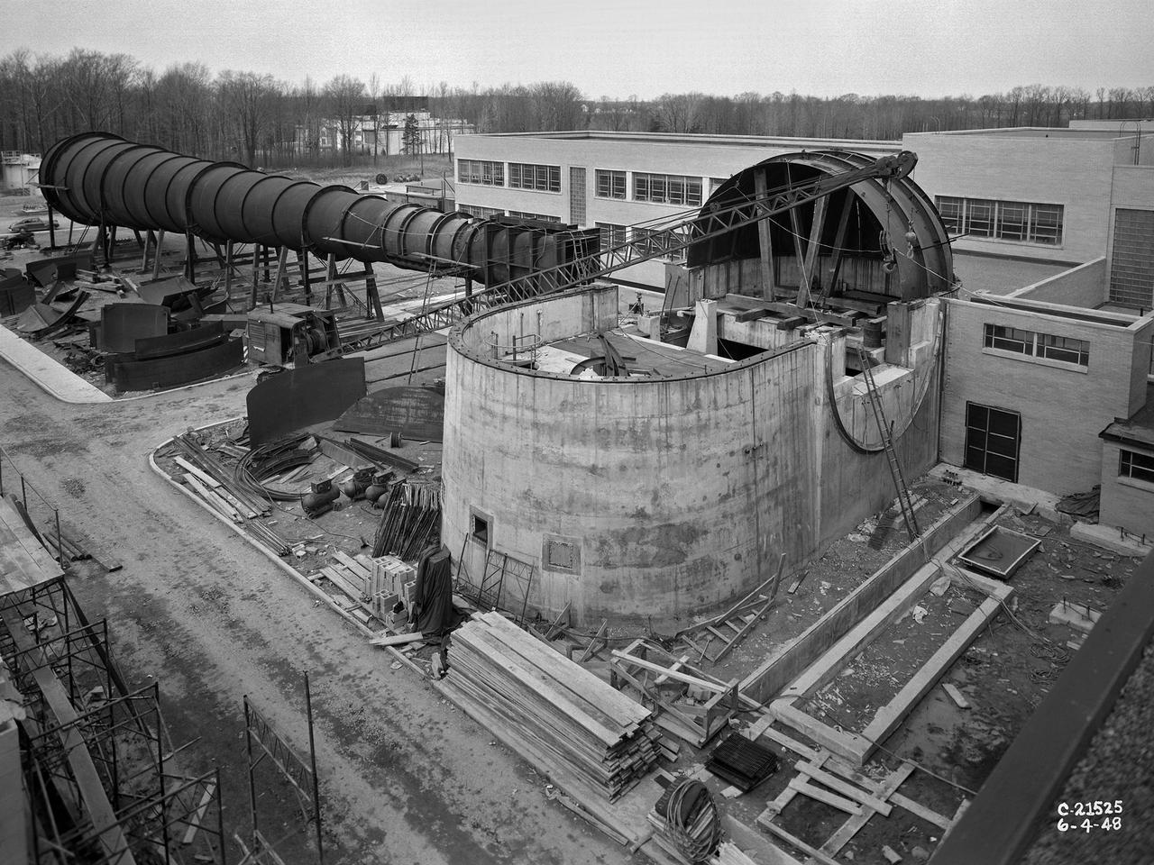
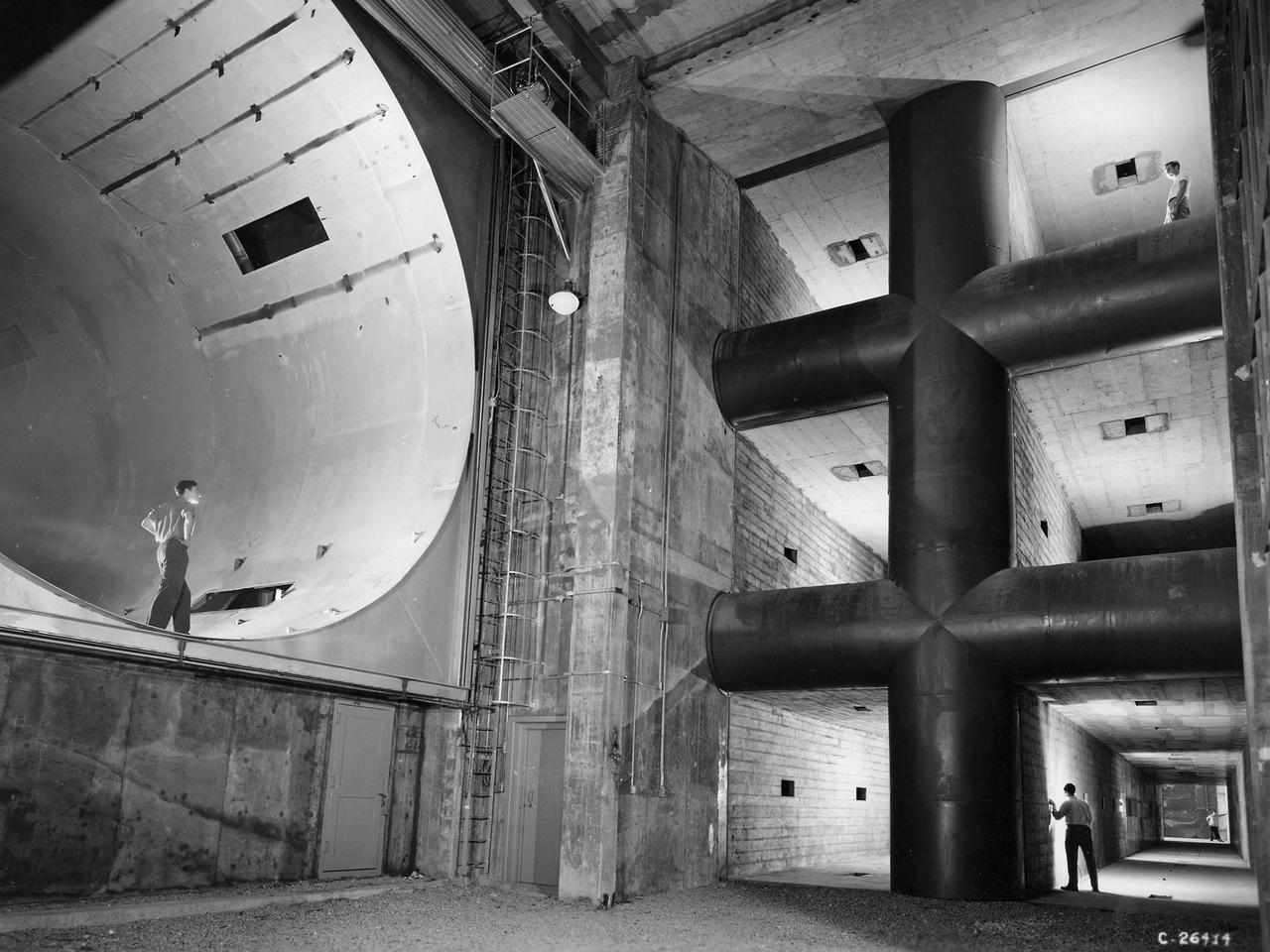
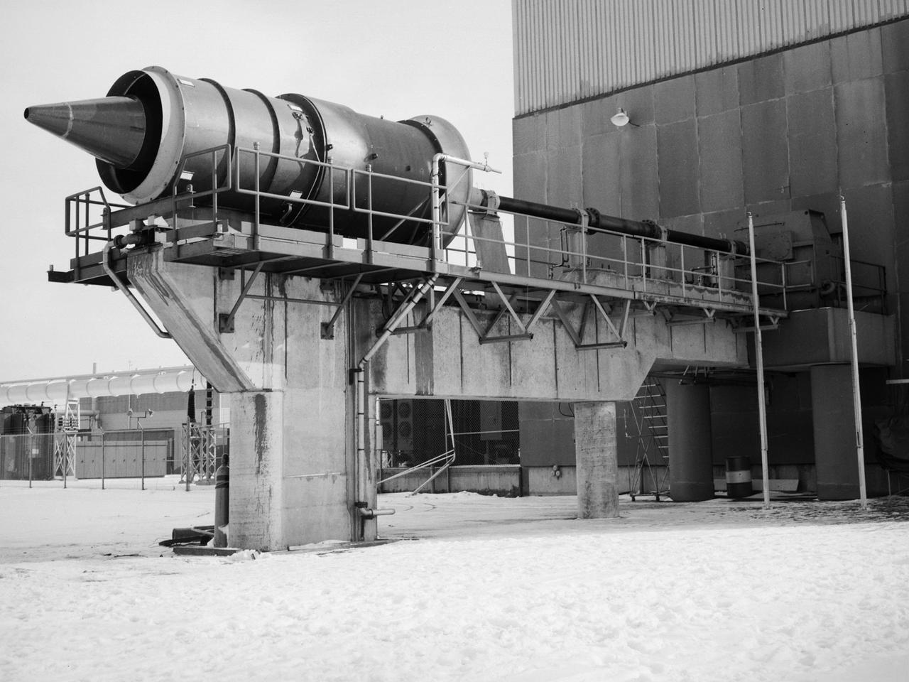
The 8- by 6-Foot Supersonic Wind Tunnel at the National Advisory Committee for Aeronautics (NACA) Lewis Flight Propulsion Laboratory was the nation’s largest supersonic facility when it began operation in April 1949. The emergence of new propulsion technologies such as turbojets, ramjets, and rockets during World War II forced the NACA and the aircraft industry to develop new research tools. In late 1945 the NACA began design work for new large supersonic wind tunnels at its three laboratories. The result was the 4- by 4-Foot Supersonic Wind Tunnel at Langley Memorial Aeronautical Laboratory, 6- by 6-foot supersonic wind tunnel at Ames Aeronautical Laboratory, and the largest facility, the 8- by 6-Foot Supersonic Wind Tunnel in Cleveland. The two former tunnels were to study aerodynamics, while the 8- by 6 facility was designed for supersonic propulsion. The 8- by 6-Foot Supersonic Wind Tunnel was used to study propulsion systems, including inlets and exit nozzles, combustion fuel injectors, flame holders, exit nozzles, and controls on ramjet and turbojet engines. Flexible sidewalls alter the tunnel’s nozzle shape to vary the Mach number during operation. A seven-stage axial compressor, driven by three electric motors that yield a total of 87,000 horsepower, generates air speeds from Mach 0.36 to 2.0. A section of the tunnel is seen being erected in this photograph.
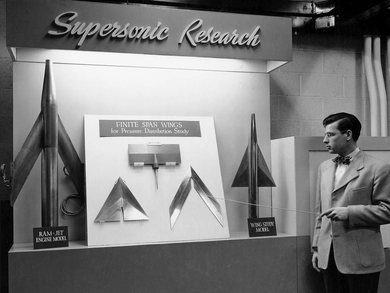
On March 22, 1946, 250 members of the Institute of Aeronautical Science toured the NACA’s Aircraft Engine Research Laboratory. NACA Chairman Jerome Hunsaker and Secretary John Victory were on hand to brief the attendees in the Administration Building before the visited the lab’s test facilities. At each of the twelve stops, researchers provided brief presentations on their work. Topics included axial flow combustors, materials for turbine blades, engine cooling, icing prevention, and supersonic flight. The laboratory reorganized itself in October 1945 as World War II came to an end to address newly emerging technologies such as the jet engine, rockets, and high-speed flight. While design work began on what would eventually become the 8- by 6-Foot Supersonic Wind Tunnel, NACA Lewis quickly built several small supersonic tunnels. These small facilities utilized the Altitude Wind Tunnel’s massive air handling equipment to generate high-speed airflow. The display seen in this photograph was set up in the building that housed the first of these wind tunnels. Eventually the building would contain three small supersonic tunnels, referred to as the “stack tunnels” because of the vertical alignment. The two other tunnels were added to this structure in 1949 and 1951. The small tunnels were used until the early 1960s to study the aerodynamic characteristics of supersonic inlets and exits.
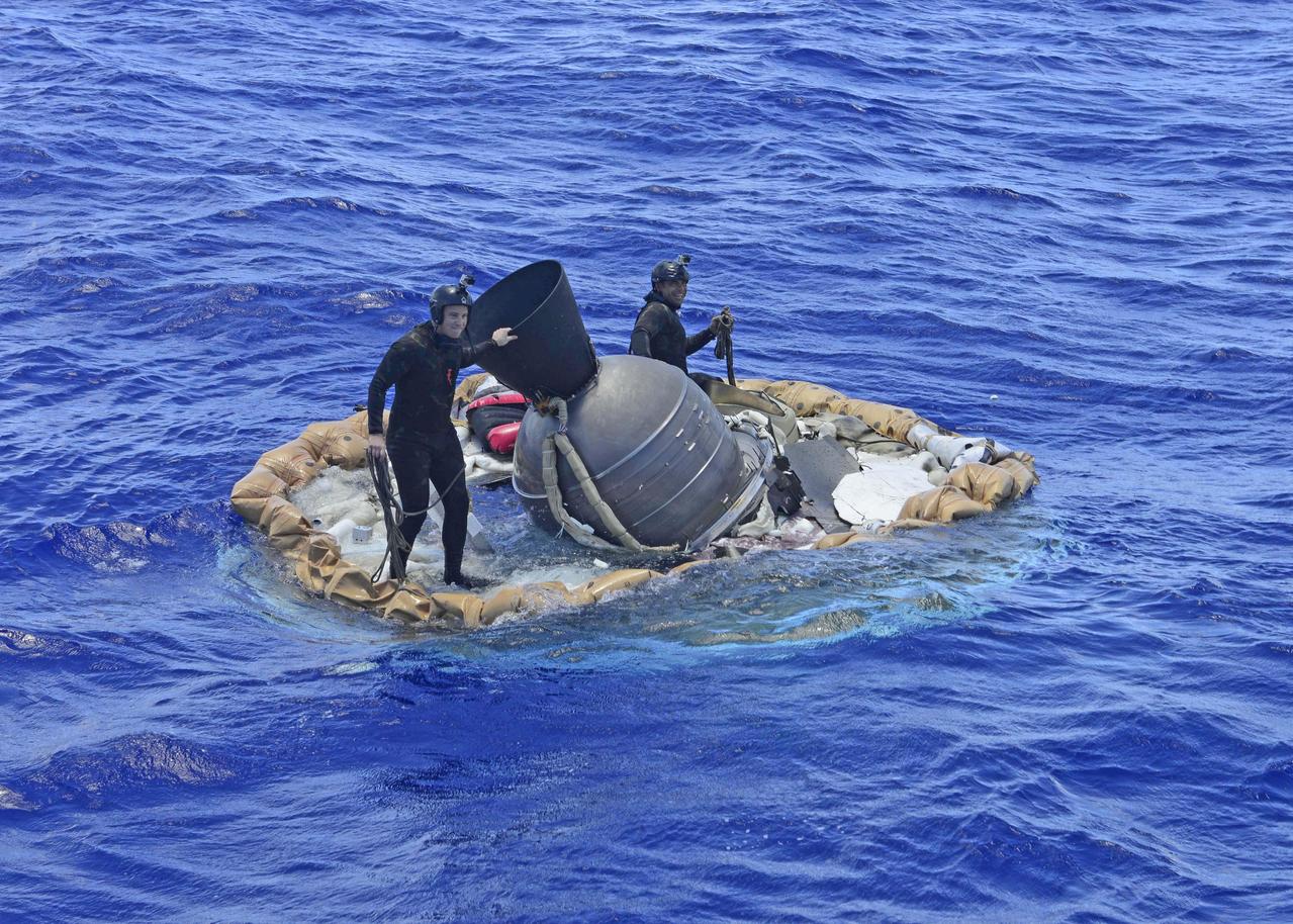
Two members of the U.S. Navy's Mobile Diving Salvage Unit (MDSU) 1 Explosive Ordnance Detachment work on recovering the test vehicle for NASA's Low-Density Supersonic Decelerator (LDSD) project. The saucer-shaped LDSD craft splashed down at 11:49 a.m. HST (2:49 PDT/5:49 p.m. EDT) Monday, June 8, 2015, in the Pacific Ocean off the west coast of the Kauai, Hawaii, after a four-hour experimental flight test that investigated new technologies for landing future robotic and human Mars missions. During the flight test, a Supersonic Inflatable Aerodynamic Decelerator (SIAD) and a supersonic parachute were deployed. The SIAD operated as expected, dramatically slowing the test vehicle's velocity. When the parachute was deployed into the supersonic slipstream, it appeared to blossom to full inflation prior to the emergence of a tear which then propagated and destroyed the parachute's canopy. As a result, the saucer's splashdown in the Pacific Ocean was hard, resulting in fracturing parts of the structure. Memory cards containing comprehensive test data -- including high-speed, high-resolution imagery recorded during the flight -- were successfully recovered. Also recovered were the test vehicle and its components, the supersonic parachute, the ballute used to deploy the parachute, and a large weather balloon that initially carried the saucer to an altitude of 120,000 feet. http://photojournal.jpl.nasa.gov/catalog/PIA19684
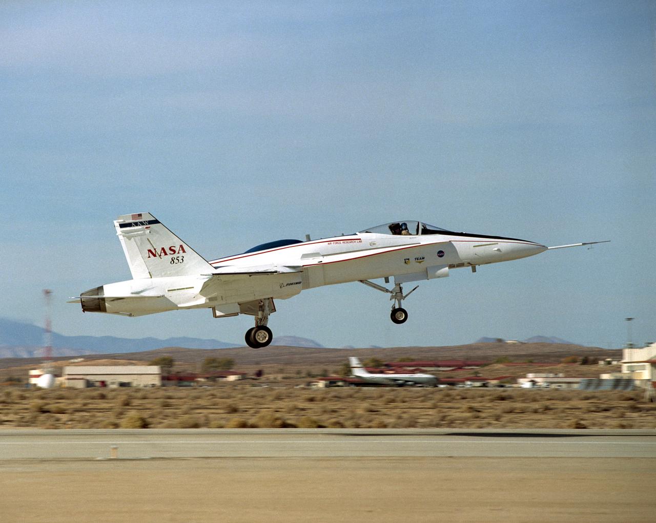
The Active Aeroelastic Wing F-18A lifts off on its first checkout flight November 15, 2002, from NASA's Dryden Flight Research Center at Edwards Air Force Base, Calif. The checkout flight initiated a two-phase NASA--Air Force flight research program that will investigate the potential of aerodynamically twisting flexible wings to improve maneuverability of high-performance aircraft at transonic and supersonic speeds.

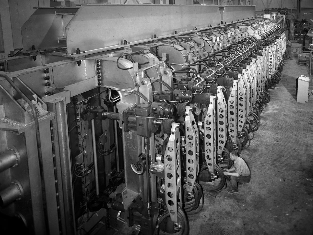
A technician at the National Advisory Committee for Aeronautics (NACA) Lewis Flight Propulsion Laboratory examines one of the massive axial-flow compressor stages that created the high-speed air flow through the 8- by 6-Foot Supersonic Wind Tunnel. The tunnel’s first run was on April 3, 1949, just over a week before this photograph was taken. The 8- by 6 was the laboratory’s first large supersonic wind tunnel and the NACA’s largest supersonic tunnel at the time. The 8- by 6-foot tunnel was originally an open-throat non-return tunnel. The supersonic air flow was blown through the tubular facility and expelled out the other end into the atmosphere with a roar. Complaints from the local community led to the addition of a muffler at the tunnel exit in 1956 and the eventual addition of a return leg. The return leg allowed the tunnel to be operated as either an open system with large doors venting directly to the atmosphere for propulsion system tests or as a closed loop for aerodynamic tests. The air flow was generated by a large seven-stage axial-flow compressor, seen in this photograph, that was powered by three electric motors with a combined 87,000 horsepower. The system required 36,000 kilowatts of power per hour to generate wind velocities of Mach 1.5, and 72,000 kilowatts per hour for Mach 2.0.
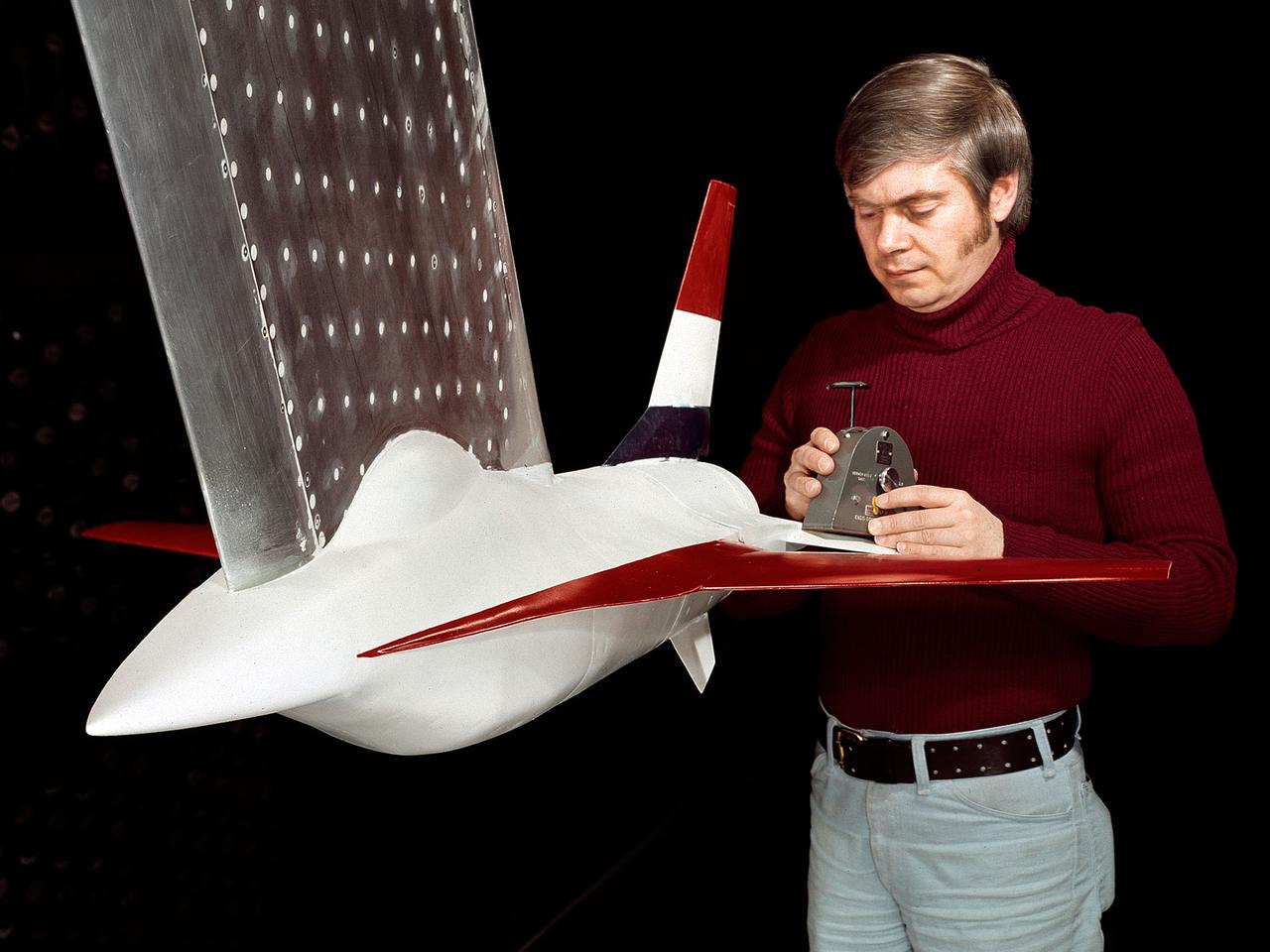
A model of the General Dynamics YF-16 Fighting Falcon in the test section of the 8- by 6-Foot Supersonic Wind Tunnel at the National Aeronautics and Space Administration (NASA) Lewis Research Center. The YF-16 was General Dynamics response to the military’s 1972 request for proposals to design a new 20,000-pound fighter jet with exceptional acceleration, turn rate, and range. The aircraft included innovative design elements to help pilots survive turns up to 9Gs, a new frameless bubble canopy, and a Pratt and Whitney 24,000-pound thrust F-100 engine. The YF-16 made its initial flight in February 1974, just six weeks before this photograph, at Edwards Air Force Base. Less than a year later, the Air Force ordered 650 of the aircraft, designated as F-16 Fighting Falcons. The March and April 1974 tests in the 8- by 6-foot tunnel analyzed the aircraft’s fixed-shroud ejector nozzle. The fixed-nozzle area limited drag, but also limited the nozzle’s internal performance. NASA researchers identified and assessed aerodynamic and aerodynamic-propulsion interaction uncertainties associated the prototype concept. YF-16 models were also tested extensively in the 11- by 11-Foot Transonic Wind Tunnel and 9- by 7-Foot Supersonic Wind Tunnel at Ames Research Center and the 12-Foot Pressure Wind Tunnel at Langley Research Center.
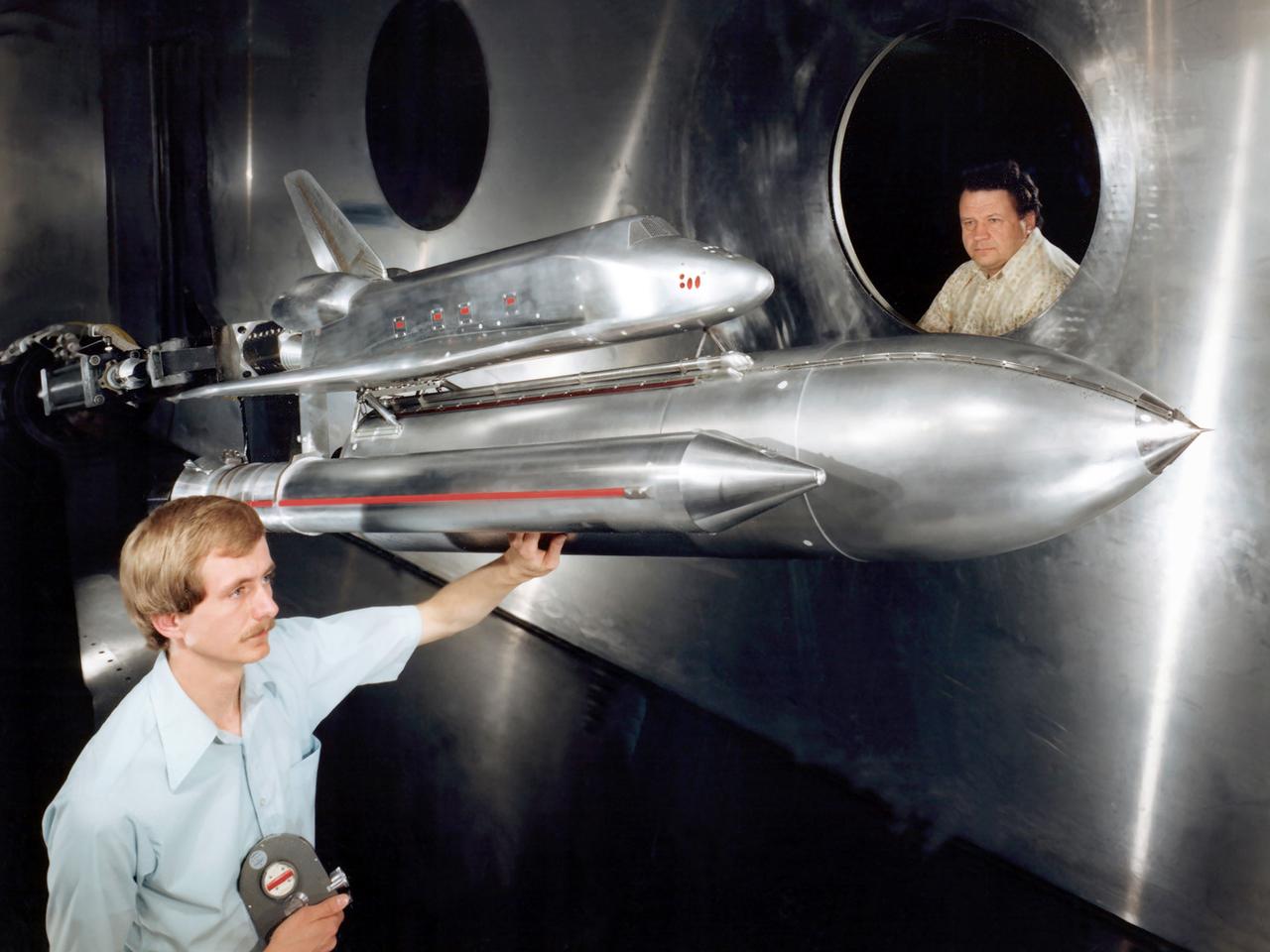
Technicians examine a scale model of the space shuttle used to obtain pressure data during tests in the 10- by 10-Foot Supersonic Wind Tunnel at the National Aeronautics and Space Administration (NASA) Lewis Research Center. Lewis researchers used the 10- by 10 tunnel extensively in the 1970s to study shuttle configurations in order to forecast conditions during an actual flight. These tests included analysis of the solid rocket boosters’ aerodynamics, orbiter forebody angle -of -attack and air speed, base heating for entire shuttle, and engine-out loads. The test seen in this photograph used a 3.5- percent scale aluminum alloy model of the entire launch configuration. The program was designed to obtain aerodynamic pressure data. The tests were part of a larger program to study possible trouble areas for the shuttle’s new Advanced Flexible Reusable Surface Insulation. The researchers obtained aeroacoustic data and pressure distributions from five locations on the model. Over 100 high-temperature pressure transducers were attached to the model. Other portions of the test program were conducted at Lewis’ 8- by 6-Foot Supersonic Wind Tunnel and the 11- by 11-Foot Transonic Wind Tunnel at Ames Research Center.
The 8- by 6-Foot Supersonic Wind Tunnel at the National Advisory Committee for Aeronautics (NACA) Lewis Flight Propulsion Laboratory was the largest supersonic wind tunnel in the nation at the time and the only one able to test full-scale engines at supersonic speeds. The 8- by 6 was designed as a non-return and open-throat tunnel. A large compressor created the air flow at one end of the tunnel, squeezed the flow to increase its velocity just before the test section, then reduced the velocity, and expelled it into the atmosphere at the other end of the tunnel. This design worked well for initial aerodynamic testing, but the local community was literally rattled by the noise and vibrations when researchers began running engines in the test section in January 1950. The NACA’s most modern wind tunnel was referred to as “an 87,000-horsepower bugle aimed at the heart of Cleveland.” NACA Lewis responded to the complaints by adding an acoustic housing at the end of the tunnel to dampen the noise. The structure included resonator chambers and a reinforced concrete muffler structure. Modifications continued over the years. A return leg was added, and a second test section, 9 -by 15-foot, was incorporated in the return leg in the 1960s. Since its initial operation in 1948, the 8- by 6-foot tunnel has been aggressively used to support the nation's aeronautics and space programs for the military, industry, and academia.
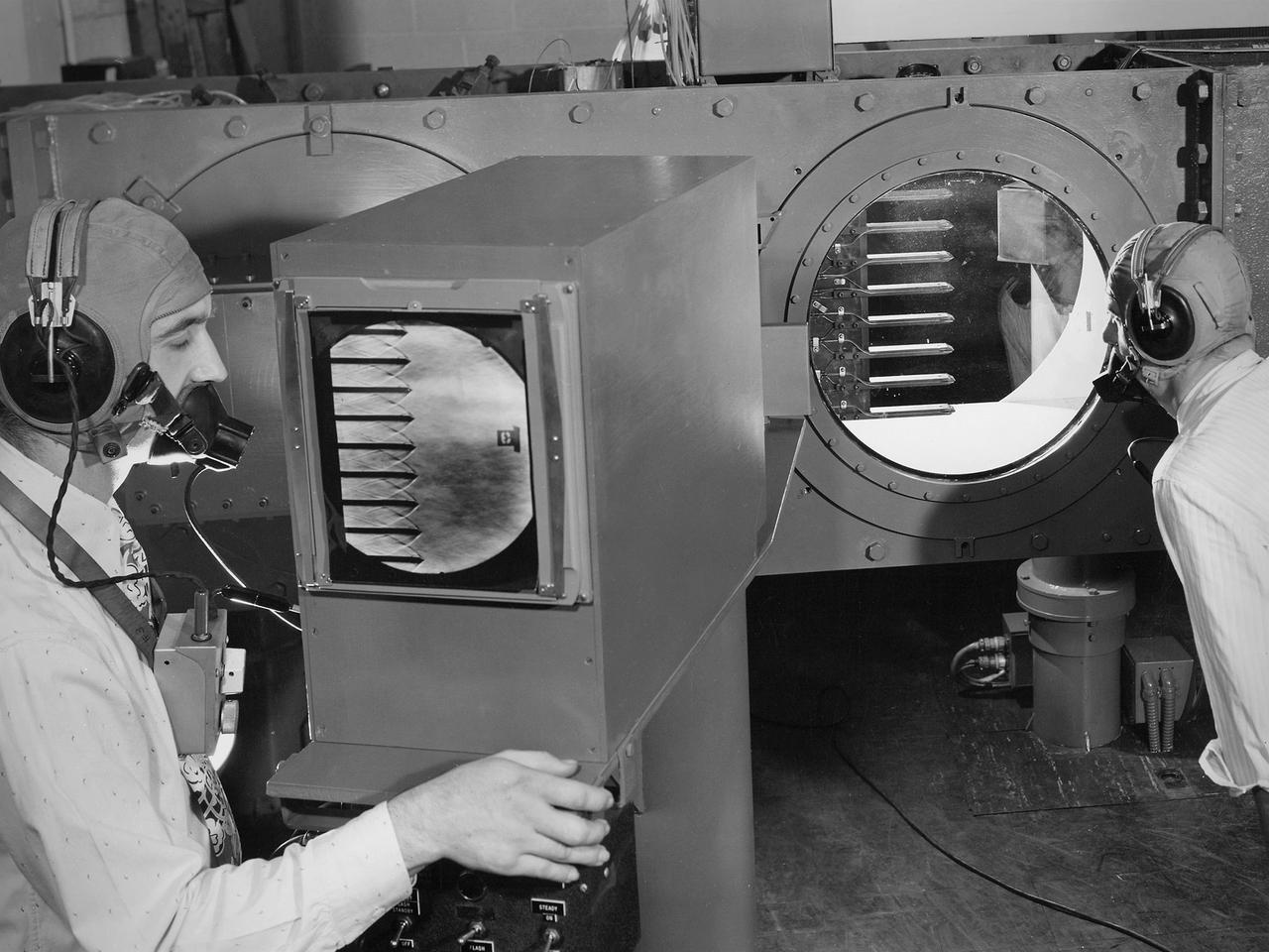
Engineers calibrate one of three small supersonic wind tunnels that were collectively referred to as the “Stack Tunnels” at the National Advisory Committee for Aeronautics (NACA) Lewis Flight Propulsion Laboratory. In late 1945 NACA Lewis reorganized its staff and began constructing a new wave of facilities to address high-speed flight and the turbojet and rocket technologies that emerged during World War II. While design work began on what would eventually become the 8- by 6-Foot Supersonic Wind Tunnel, NACA Lewis quickly built several small supersonic tunnels. These small facilities utilized the Altitude Wind Tunnel’s massive air handling equipment. Three of the small tunnels were built vertically on top of each other and thus were known as the Stack Tunnels. The first of the Stack Tunnels was an 18- by 18-inch tunnel that began operating in August 1945 at speeds up to Mach 1.91. The second tunnel, whose 24- by 24-inch test section is shown here, was added in 1949. It could generate air flows up to Mach 3.96. A third tunnel with an 18- by 18-inch test section began operating in 1951 with speeds up to Mach 3.05. The small tunnels were used until the early 1960s to study the aerodynamic characteristics of supersonic inlets and exits. The technician to the left in this photograph is operating a Schlieren camera to view the air flow dynamics inside the 24- by 24-inch test section. The technician on the right is viewing the pronged test article through the circular window. They are calibrating the tunnel and its equipment to prepare for the initial test runs.
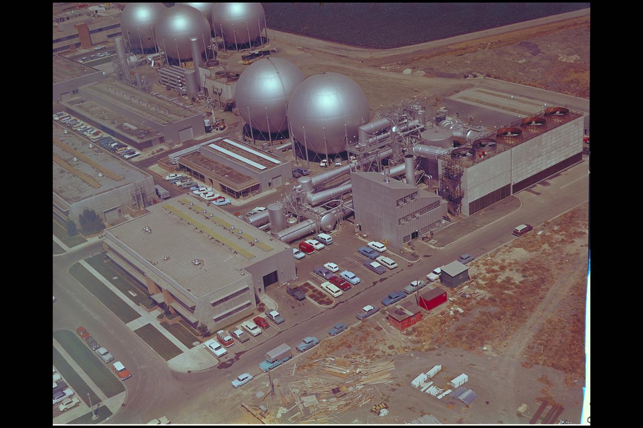
Aerial view of Gasdynamics facility in 1964 and the 20 inch helium tunnel Part of the Thermal Protection Laboratory used to research materials for heat shield applications and for aerodynamic heating and materials studies of vehicles in planetary atmospheres. This laboratory is comprised of five separate facilities: an Aerodynamic Heating Tunnel, a Heat Transfer Tunnel, two Supersonic Turbulent Ducts, and a High-Power CO2 Gasdynamic Laser. All these facilities are driven by arc-heaters, with the exception of the large, combustion-type laser. The arc-heated facilities are powered by a 20 Megawatt DC power supply. Their effluent gas stream (test gases; Air, N2, He, CO2 and mixtures; flow rates from 0.05 to 5.0 lbs/sec) discharges into a five-stage stream-ejector-driven vacuum system. The vacuum system and power supply are common to the test faciities in building N-238. All of the facilities have high pressure water available at flow rates up to 4, 000 gals/min. The data obtained from these facilities are recorded on magnetic tape or oscillographs. All forms of data can be handled whether from thermo-couples, pressure cells, pyrometers, or radiometers, etc. in addition, closed circuit T. V. monitors and various film cameras are available. (operational since 1962)
A mechanic checks the tubing on one of the many jacks which control the nozzle section of the 10- by 10-Foot Supersonic Wind Tunnel at the National Advisory Committee for Aeronautics (NACA) Lewis Flight Propulsion Laboratory. The 10- by 10-foot tunnel, which had its official opening in May 1956, was built under the Congressional Unitary Plan Act which coordinated wind tunnel construction at the NACA, Air Force, industry, and universities. The 10- by 10 was the largest of the three NACA tunnels built under the act. The 10- by 10 wind tunnel can be operated as a closed circuit for aerodynamic tests or as an open circuit for propulsion investigations. The 10-foot tall and 76-foot long stainless steel nozzle section just upstream from the test section can be adjusted to change the speed and composition of the air flow. Hydraulic jacks, seen in this photograph, flex the 1.37-inch thick walls of the tunnel nozzle. The size of the nozzle’s opening controls the velocity of the air through the test section. Seven General Electric motors capable of generating 25,000 horsepower produce the Mach 2.5 and 2.5 airflows. The facility was mostly operated at night due to its large power load requirements.

The first of three X-43A hypersonic research aircraft and its modified Pegasus® booster rocket recently underwent combined systems testing while mounted to NASA's NB-52B carrier aircraft at the Dryden Flight Research Center, Edwards, Calif. The combined systems test was one of the last major milestones in the Hyper-X research program before the first X-43A flight. The X-43A flights will be the first actual flight tests of an aircraft powered by a revolutionary supersonic-combustion ramjet ("scramjet") engine capable of operating at hypersonic speeds (above Mach 5, or five times the speed of sound). The 12-foot, unpiloted research vehicle was developed and built by MicroCraft Inc., Tullahoma, Tenn., under NASA contract. The booster was built by Orbital Sciences Corp., Dulles, Va.,After being air-launched from NASA's venerable NB-52 mothership, the booster will accelerate the X-43A to test speed and altitude. The X-43A will then separate from the rocket and fly a pre-programmed trajectory, conducting aerodynamic and propulsion experiments until it descends into the Pacific Ocean. Three research flights are planned, two at Mach 7 and one at Mach 10.
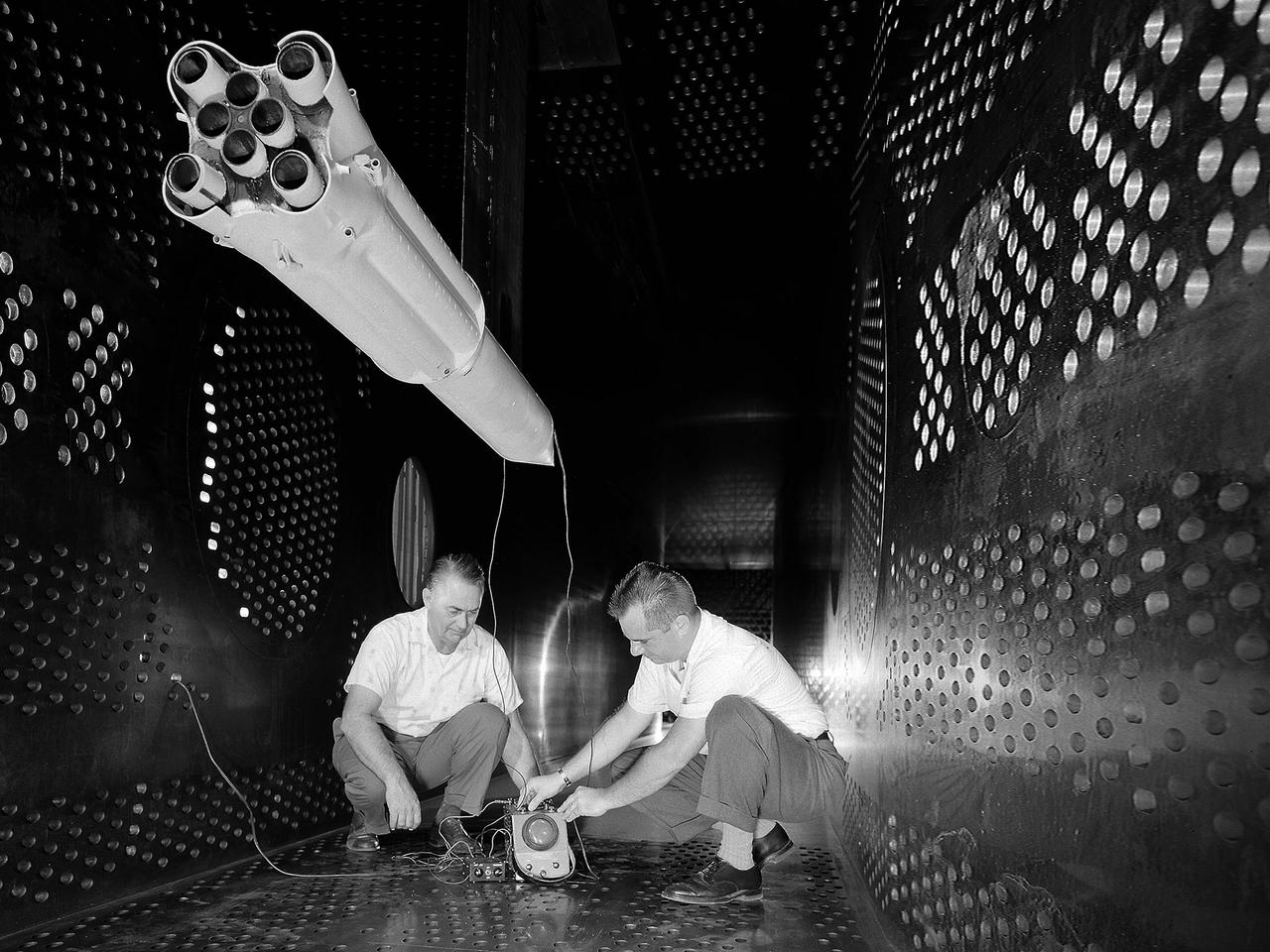
National Aeronautics and Space Administration (NASA) researchers set up instrumentation on a 0.037- scale model of a Saturn booster in the 8- by 6-Foot Supersonic Wind Tunnel at the NASA Lewis Research Center. In October 1960 Lewis researchers John Allen and Robert Wasko began a 14-month investigation of the eight-engine booster’s base heating in the tunnel. The model resembled the Saturn C-1, but only the afterbody totally mimicked the C-1. The over-heating of the lower end, or base, of the booster can cause the engines to fail or introduce aerodynamic concerns. Base heating results from the rocket engines’ exhaust heat, the recirculation of that heat into the base, and the burning of combustibles. Large boosters, like the Saturn, employed clusters of rocket engines that add to the complexity of the base heating problem. The 8- by 6-foot tunnel investigations studied the Saturn at speeds from Mach 1.0 to 2.0 using liquid oxygen and JP-4 as propellants. Researchers found that the use of cooling air scoops and external flow deflectors produced significant decreases in base heating.
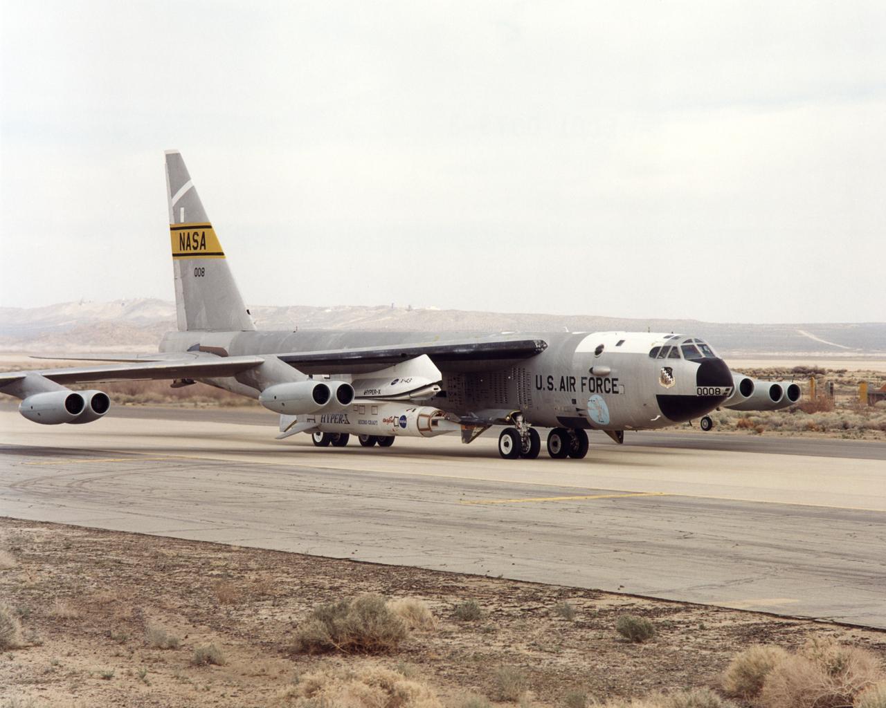
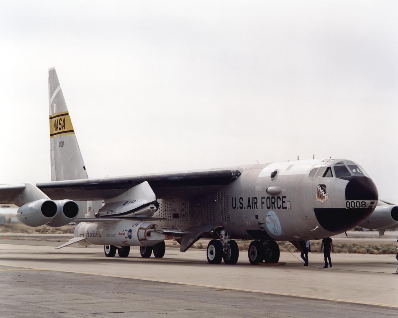
NASA's NB-52B carrier aircraft rolls down a taxiway at Edwards Air Force Base with the X-43A hypersonic research aircraft and its modified Pegasus® booster rocket slung from a pylon under its right wing. Part of a combined systems test conducted by NASA's Dryden Flight Research Center at Edwards, the taxi test was one of the last major milestones in the Hyper-X research program before the first X-43A flight. The X-43A flights will be the first actual flight tests of an aircraft powered by a revolutionary supersonic-combustion ramjet ("scramjet") engine capable of operating at hypersonic speeds (above Mach 5, or five times the speed of sound). The 12-foot, unpiloted research vehicle was developed and built by MicroCraft Inc., Tullahoma, Tenn., under NASA contract. The booster was built by Orbital Sciences Corp., Dulles, Va.,After being air-launched from NASA's venerable NB-52 mothership, the booster will accelerate the X-43A to test speed and altitude. The X-43A will then separate from the rocket and fly a pre-programmed trajectory, conducting aerodynamic and propulsion experiments until it descends into the Pacific Ocean. Three research flights are planned, two at Mach 7 and one at Mach 10, with the first tentatively scheduled for late spring to early summer, 2001.
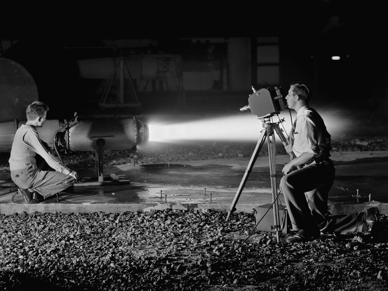
A National Advisory Committee for Aeronautics (NACA) photographer films the test of a ramjet engine at the Lewis Flight Propulsion Laboratory. The laboratory had an arsenal of facilities to test the engines and their components, and immersed itself in the study of turbojet and ramjet engines during the mid-1940s. Combustion, fuel injection, flameouts, and performance at high altitudes were of particular interest to researchers. They devised elaborate schemes to instrument the engines in order to record temperature, pressure, and other data. Many of the tests were also filmed so Lewis researchers could visually review the combustion performance along with the data. The photographer in this image was using high-speed film to document a thrust augmentation study at Lewis’ Jet Static Propulsion Laboratory. The ramjet in this photograph was equipped with a special afterburner as part of a general effort to improve engine performance. Lewis’ Photo Lab was established in 1942. The staff was expanded over the next few years as more test facilities became operational. The Photo Lab’s staff and specialized equipment have been key research tools for decades. They accompany pilots on test flights, use high-speed cameras to capture fleeting processes like combustion, and work with technology, such as the Schlieren camera, to capture supersonic aerodynamics. In addition, the group has documented construction projects, performed publicity work, created images for reports, and photographed data recording equipment.
The X-43A hypersonic research aircraft and its modified Pegasus® booster rocket are nestled under the wing of NASA's NB-52B carrier aircraft during pre-flight systems testing at the Dryden Flight Research Center, Edwards, Calif. The combined systems test was one of the last major milestones in the Hyper-X research program before the first X-43A flight. The X-43A flights will be the first actual flight tests of an aircraft powered by a revolutionary supersonic-combustion ramjet ("scramjet") engine capable of operating at hypersonic speeds (above Mach 5, or five times the speed of sound). The 12-foot, unpiloted research vehicle was developed and built by MicroCraft Inc., Tullahoma, Tenn., under NASA contract. The booster was built by Orbital Sciences Corp., Dulles, Va. After being air-launched from NASA's venerable NB-52 mothership, the booster will accelerate the X-43A to test speed and altitude. The X-43A will then separate from the rocket and fly a pre-programmed trajectory, conducting aerodynamic and propulsion experiments until it descends into the Pacific Ocean. Three research flights are planned, two at Mach 7 and one at Mach 10.
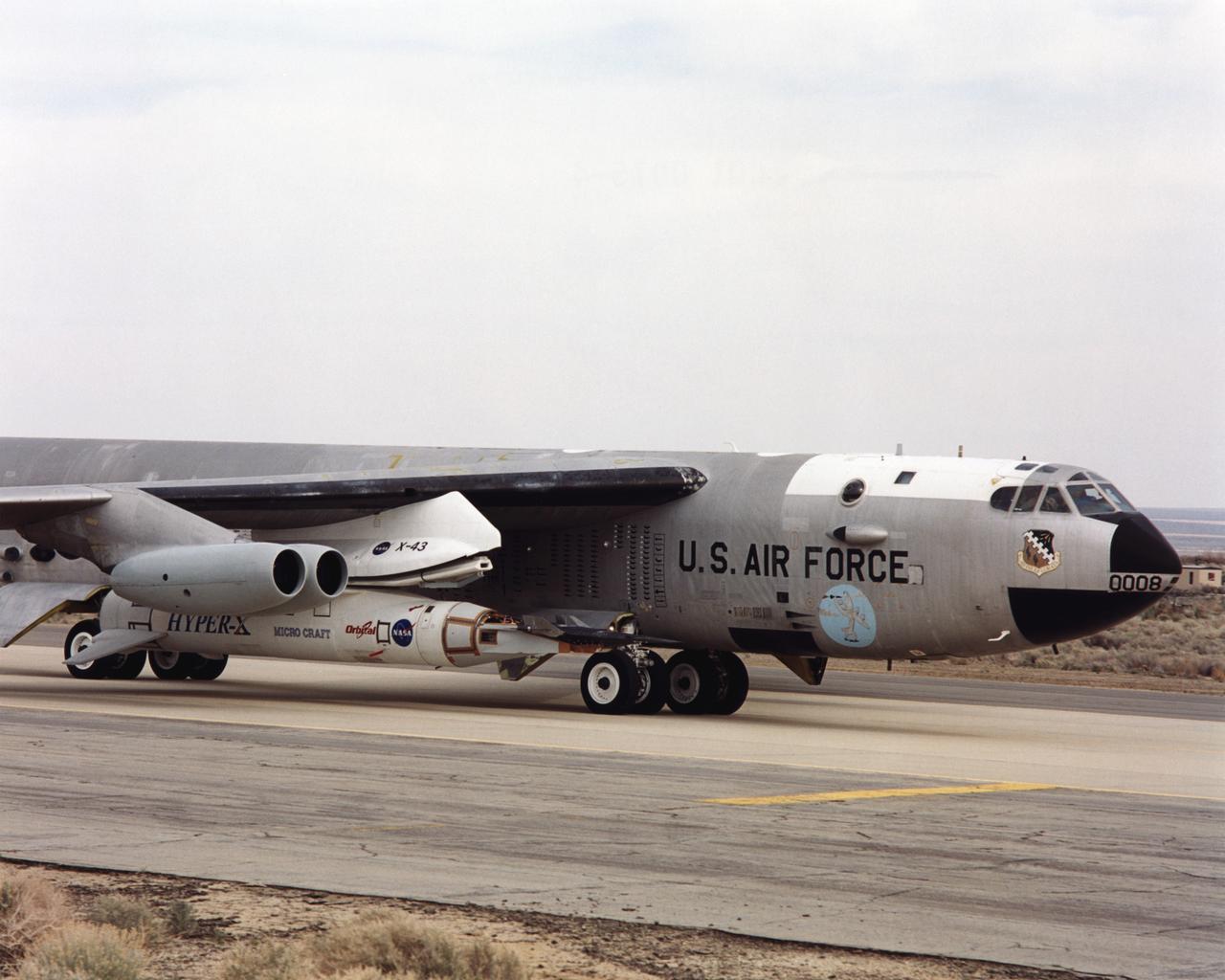
As part of a combined systems test conducted by NASA Dryden Flight Research Center, NASA's NB-52B carrier aircraft rolls down a taxiway at Edwards Air Force Base with the X-43A hypersonic research aircraft and its modified Pegasus® booster rocket attached to a pylon under its right wing. The taxi test was one of the last major milestones in the Hyper-X research program before the first X-43A flight. The X-43A flights will be the first actual flight tests of an aircraft powered by a revolutionary supersonic-combustion ramjet ("scramjet") engine capable of operating at hypersonic speeds (above Mach 5, or five times the speed of sound). The 12-foot, unpiloted research vehicle was developed and built by MicroCraft Inc., Tullahoma, Tenn., under NASA contract. The booster was built by Orbital Sciences Corp., Dulles, Va. After being air-launched from NASA's venerable NB-52 mothership, the booster will accelerate the X-43A to test speed and altitude. The X-43A will then separate from the rocket and fly a pre-programmed trajectory, conducting aerodynamic and propulsion experiments until it descends into the Pacific Ocean. Three research flights are planned, two at Mach 7 and one at Mach 10.
A Highly Maneuverable Aircraft Technology (HiMAT) inlet model installed in the test section of the 8- by 6-Foot Supersonic Wind Tunnel at the National Aeronautics and Space Administration (NASA) Lewis Research Center. Engineers at the Ames Research Center, Dryden Flight Research Center, and Rockwell International designed two pilotless subscale HiMAT vehicles in the mid-1970s to study new design concepts for fighter aircraft in the transonic realm without risking the lives of test pilots. The aircraft used sophisticated technologies such as advanced aerodynamics, composite materials, digital integrated propulsion control, and digital fly-by-wire control systems. In late 1977 NASA Lewis studied the HiMAT’s General Electric J85-21 jet engine in the Propulsion Systems Laboratory. The researchers charted the inlet quality with various combinations anti-distortion screens. HiMAT employed a relatively short and curved inlet compared to actual fighter jets. In the spring of 1979, Larry Smith led an in-depth analysis of the HiMAT inlet in the 8- by 6 tunnel. The researchers installed vortex generators to battle flow separation in the diffuser. The two HiMAT aircraft performed 11 hours of flying over the course of 26 missions from mid-1979 to January 1983 at Dryden and Ames. Although the HiMAT vehicles were considered to be overly complex and expensive, the program yielded a wealth of data that would validate computer-based design tools.

National Aeronautics and Space Administration (NASA) engineer Robert Jeracki prepares a Hamilton Standard SR-1 turboprop model in the test section of the 8- by 6-Foot Supersonic Wind Tunnel at the Lewis Research Center. Lewis researchers were analyzing a series of eight-bladed propellers in their wind tunnels to determine their operating characteristics at speeds up to Mach 0.8. The program, which became the Advanced Turboprop, was part of a NASA-wide Aircraft Energy Efficiency Program which was designed to reduce aircraft fuel costs by 50 percent. The ATP concept was different from the turboprops in use in the 1950s. The modern versions had at least eight blades and were swept back for better performance. After Lewis researchers developed the advanced turboprop theory and established its potential performance capabilities, they commenced an almost decade-long partnership with Hamilton Standard to develop, verify, and improve the concept. A series of 24-inch scale models of the SR-1 with different blade shapes and angles were tested in Lewis’ wind tunnels. A formal program was established in 1978 to examine associated noise levels, aerodynamics, and the drive system. The testing of the large-scale propfan was done on test rigs, in large wind tunnels, and, eventually, on aircraft.

National Aeronautics and Space Administration (NASA) researcher John Carpenter inspects an aircraft model with a four-fan thrust reverser which would be studied in the 9- by 15-Foot Low Speed Wind Tunnel at the Lewis Research Center. Thrust reversers were introduced in the 1950s as a means for slowing high-speed jet aircraft during landing. Engineers sought to apply the technology to Vertical and Short Takeoff and Landing (VSTOL) aircraft in the 1970s. The new designs would have to take into account shorter landing areas, noise levels, and decreased thrust levels. A balance was needed between the thrust reverser’s efficiency, its noise generation, and the engine’s power setting. This model underwent a series of four tests in the 9- by 15-foot tunnel during April and May 1974. The model, with a high-wing configuration and no tail, was equipped with four thrust-reverser engines. The investigations included static internal aerodynamic tests on a single fan/reverser, wind tunnel isolated fan/reverser thrust tests, installation effects on a four-fan airplane model in a wind tunnel, and single reverser acoustic tests. The 9-by 15 was built inside the return leg of the 8- by 6-Foot Supersonic Wind Tunnel in 1968. The facility generates airspeeds from 0 to 175 miles per hour to evaluate the aerodynamic performance and acoustic characteristics of nozzles, inlets, and propellers, and investigate hot gas re-ingestion of advanced VSTOL concepts. John Carpenter was a technician in the Wind Tunnels Service Section of the Test Installations Division.
The Fan Noise Test Facility built at the Lewis Research Center to obtain far-field noise data for the National Aeronautics and Space Administration (NASA) and General Electric Quiet Engine Program. The engine incorporated existing noise reduction methods into an engine of similar power to those that propelled the Boeing 707 or McDonnell-Douglas DC-8 airliner. The new the low-bypass ratio turbofan engines of the 1960s were inherently quieter than their turbojet counterparts, researchers had a better grasp of the noise generation problem, and new acoustic technologies had emerged. Lewis contracted General Electric in 1969 to build and aerodynamically test three experimental engines with 72-inch diameter fans. The engines were then brought to Lewis and tested with an acoustically treated nacelle. This Fan Noise Test Facility was built off of the 10- by 10-Foot Supersonic Wind Tunnel’s Main Compressor and Drive Building. Lewis researchers were able to isolate the fan’s noise during these initial tests by removing the core of the engine. The Lewis test rig drove engines to takeoff tip speeds of 1160 feet per second. The facility was later used to test a series of full-scale model fans and fan noise suppressors to be used with the quiet engine. NASA researchers predicted low-speed single-stage fans without inlet guide vanes and with large spacing between rotors and stators would be quieter. General Electric modified a TF39 turbofan engine by removing the the outer protion of the fan and spacing the blade rows of the inner portion. The tests revealed that the untreated version of the engine generated less noise than was anticipated, and the acoustically treated nacelle substantially reduced engine noise.
National Aeronautics and Space Administration (NASA) Convair F-106B Delta Dart with a 32-spoke nozzle installed on its General Electric J85 test engine. Lewis acquired a Delta Dart fighter in 1966 to study the components for propulsion systems that could be applied to supersonic transport aircraft at transonic speeds. The F-106B was modified with two General Electric J85-13 engines under its wings to study these components. The original test plan was expanded to include the study of boattail drag, noise reduction, and inlets. From February to July 1971 the modified F-106B was used to study different ejector nozzles. Researchers conducted both acoustic and aerodynamic tests on the ground and in flight. Several models were created to test different suppression methods. NASA Lewis’ conical nozzle was used as the baseline configuration. Flightline and sideline microphones were set up on the ground. The F-106B would idle its own engine and buzz the recording station from an altitude of 300 feet at Mach 0.4 with the test engines firing. Researchers found that the suppression of the perceived noise level was usually lower during flight than the researchers had statistically predicted. The 64 and 32-spoke nozzles performed well in actual flight, but the others nozzles tended to negatively affect the engine’s performance. Different speeds or angles- -of-attack sometimes changed the noise levels. In the end, no general conclusions could be applied to all the nozzles.
The second of three X-43A hypersonic research aircraft, shown here in its protective shipping jig, arrived at NASA's Dryden Flight Research Center, Edwards, California, on January 31, 2001. The arrival of the second X-43A from its manufacturer, MicroCraft, Inc., of Tullahoma, Tenn., followed by only a few days the mating of the first X-43A and its specially-designed adapter to the first stage of a modified Pegasus® booster rocket. The booster, built by Orbital Sciences Corp., Dulles, Va., will accelerate the 12-foot-long, unpiloted research aircraft to a predetermined altitude and speed after the X-43A/booster "stack" is air-launched from NASA's venerable NB-52 mothership. The X-43A will then separate from the rocket and fly a pre-programmed trajectory, conducting aerodynamic and propulsion experiments until it impacts into the Pacific Ocean. Three research flights are planned, two at Mach 7 and one at Mach 10 (seven and 10 times the speed of sound respectively) with the first tentatively scheduled for early summer, 2001. The X-43A is powered by a revolutionary supersonic-combustion ramjet ("scramjet") engine, and will use the underbody of the aircraft to form critical elements of the engine. The forebody shape helps compress the intake airflow, while the aft section acts as a nozzle to direct thrust. The X-43A flights will be the first actual flight tests of an aircraft powered by an air-breathing scramjet engine.
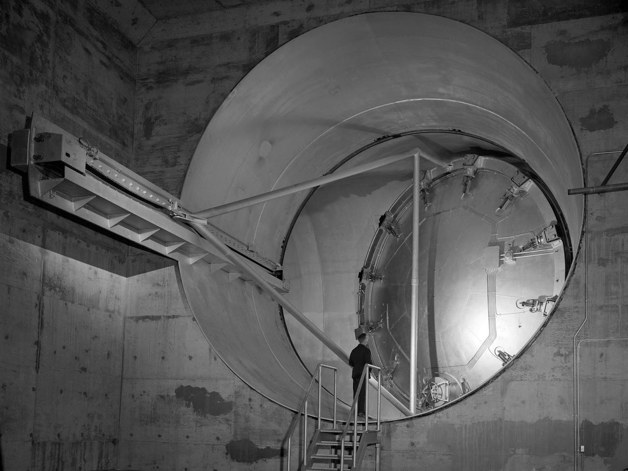
A 24-foot diameter swing valve is seen in an open position inside the new 10- by 10-Foot Supersonic Wind Tunnel at the National Advisory Committee for Aeronautics (NACA) Lewis Flight Propulsion Laboratory. The 10- by 10 was the most powerful propulsion wind tunnel in the nation. After over three years of construction the tunnel was ready to conduct its first tests in early 1956. The 10- by 10-foot tunnel was part of Congress’ Unitary Plan Act which coordinated wind tunnel construction at the NACA, Air Force, industry, and universities. The 10- by 10 was the largest of the three NACA tunnels built under the act. This large swinging valve is critical to the operation of the facility. In one position the valve seals off the tunnel exhaust, making the tunnel a closed circuit, which is used for aerodynamic testing of models. In its other position, the valve acts as a seal across the tunnel and leaves the tunnel exhaust open. This arrangement is used when engines are fired. The air going through the tunnel is taken from the atmosphere and returned to the atmosphere after one pass through the tunnel. Engines up to five feet in diameter can be tested in the 10- by 10-foot test section. Air flows up to Mach 3.5 can be fed through the test section by a 250,000-horsepower axial-flow compressor fan. The incoming air must be dehumidified and cooled so that the proper conditions are present for the test. A large air dryer with 1,890 tons of activated alumina soaks up 1.5 tons of water per minute from the air flow. A cooling apparatus equivalent to 250,000 household air conditioners is used to cool the air.
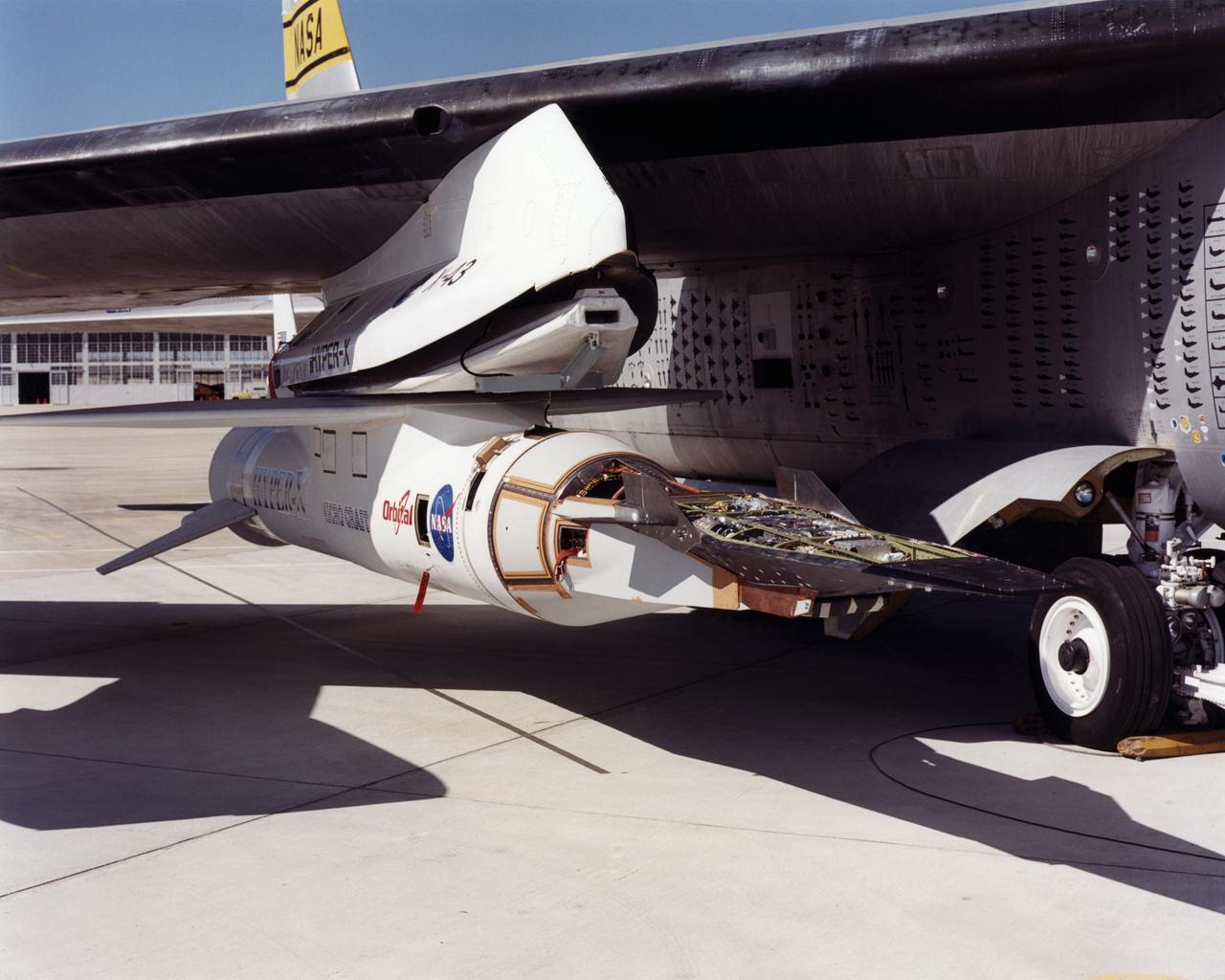
The first of three X-43A hypersonic research aircraft and its modified Pegasus® booster rocket recently underwent combined systems testing while mounted to NASA's NB-52B carrier aircraft at the Dryden Flight Research Center, Edwards, California. The combined systems test was one of the last major milestones in the Hyper-X research program before the first X-43A flight. One of the major goals of the Hyper-X program is flight validation of airframe-integrated, air-breathing propulsion system, which so far have only been tested in ground facilities, such as wind tunnels. The X-43A flights will be the first actual flight tests of an aircraft powered by a revolutionary supersonic-combustion ramjet ("scramjet") engine capable of operating at hypersonic speeds above Mach 5 (five times the speed of sound). The X-43A design uses the underbody of the aircraft to form critical elements of the engine. The forebody shape helps compress the intake airflow, while the aft section acts as a nozzle to direct thrust. The 12-foot, unpiloted research vehicle was developed and built by MicroCraft Inc., Tullahoma, Tenn., under NASA contract. The booster, built by Orbital Sciences Corp., Dulles, Va., will accelerate the X-43A after the X-43A/booster "stack" is air-launched from NASA's venerable NB-52 mothership. The X-43A will separate from the rocket at a predetermined altitude and speed and fly a pre-programmed trajectory, conducting aerodynamic and propulsion experiments until it descends into the Pacific Ocean. Three research flights are planned, two at Mach 7 and one at Mach 10.