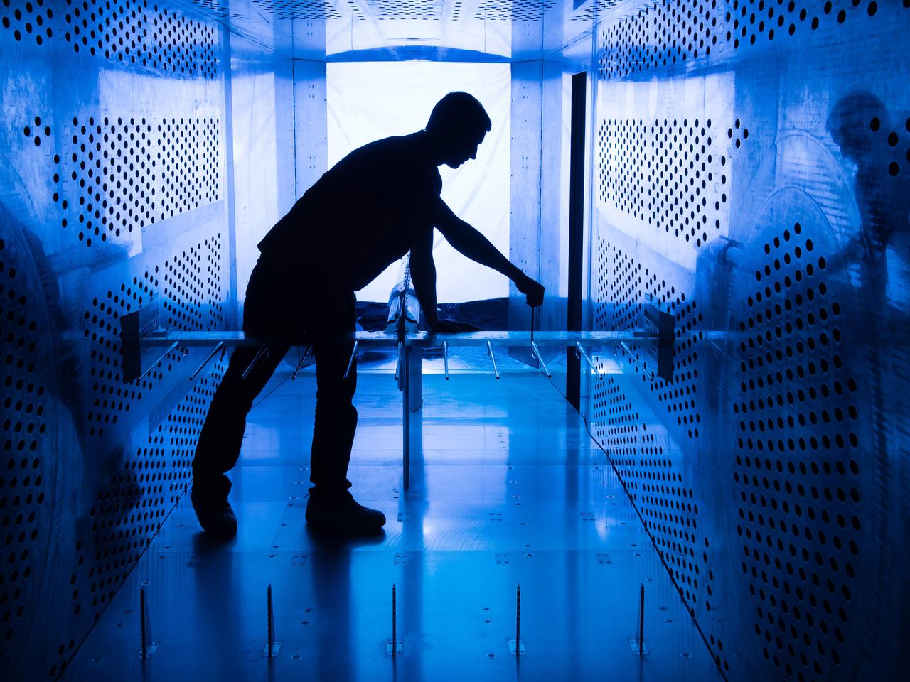
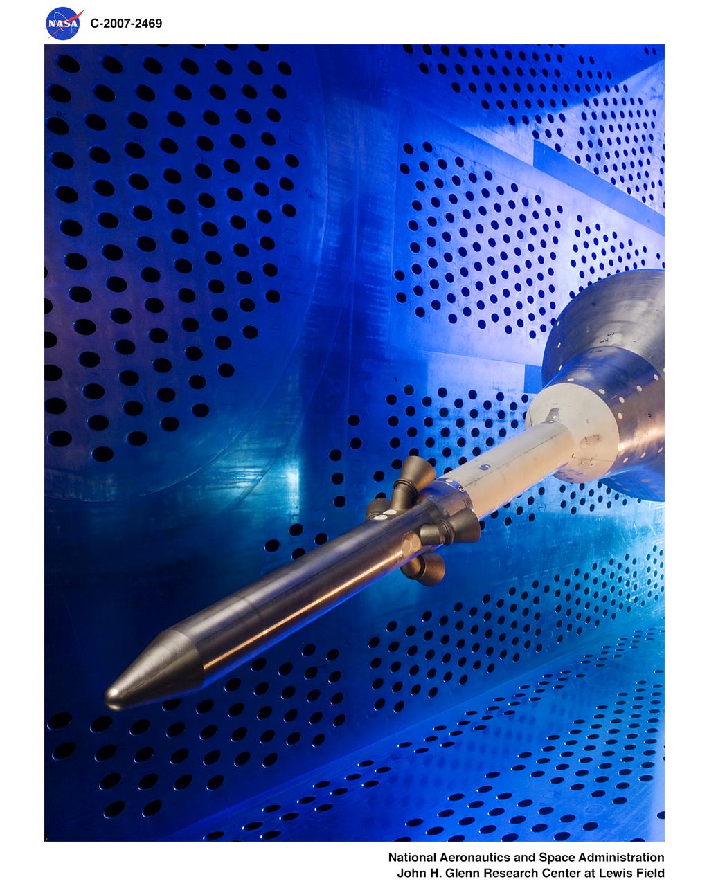
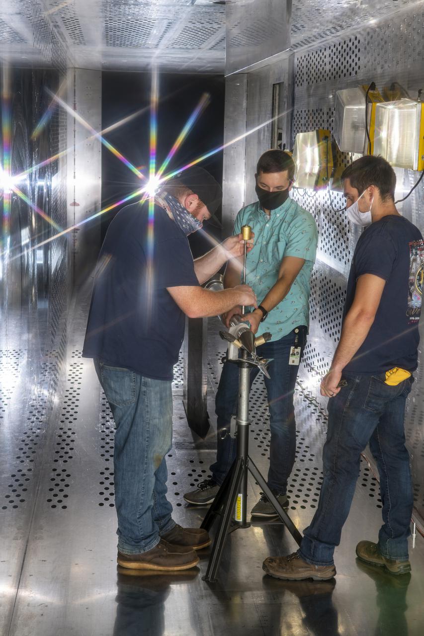
Raised Floor Calibration Hardware for the Boundary Layer Ingesting Inlet Distortion Tolerant Fan tests to be performed in the 8' x 6' Supersonic Wind Tunnel at NASA Glenn Research Center.
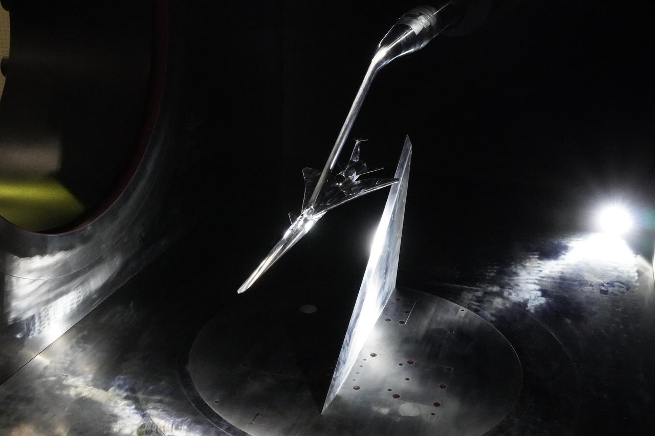
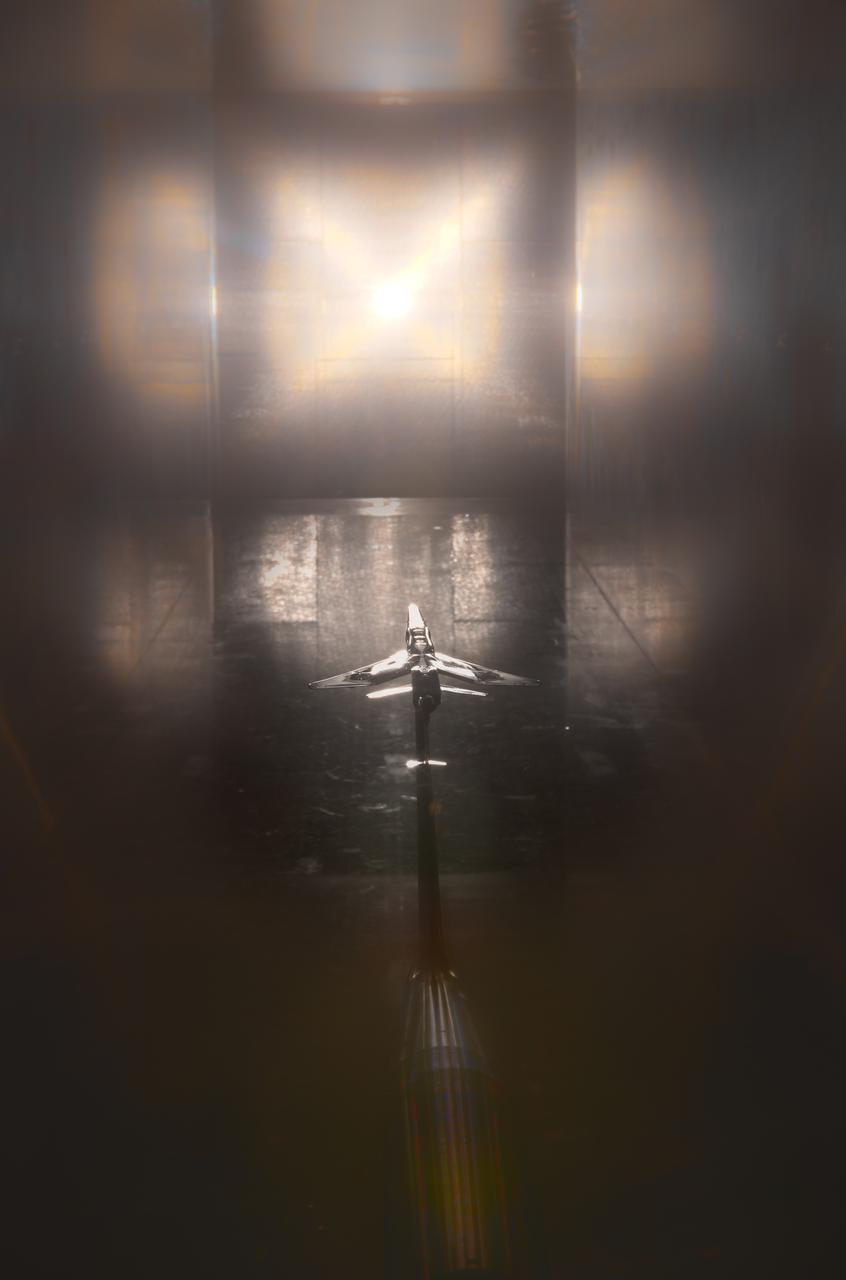
Here you see the X-59 scaled model inside the JAXA supersonic wind tunnel during critical tests related to sound predictions.
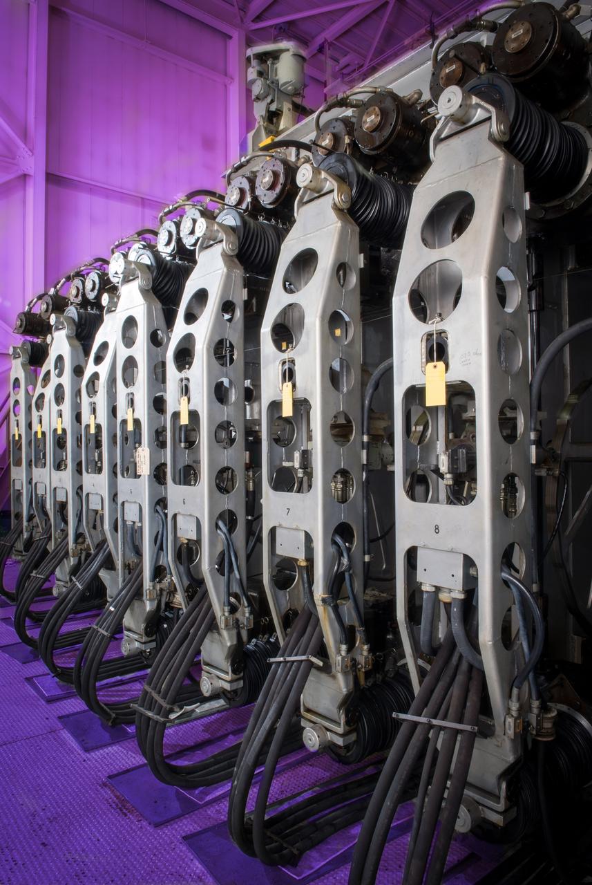
The flexwall section of NASA Glenn’s 10x10 supersonic wind tunnel is made up of two movable flexible steel sidewalls. These powerful hydraulic jacks move the walls in and out to control supersonic air speeds in the test section between Mach 2.0 and 3.5.
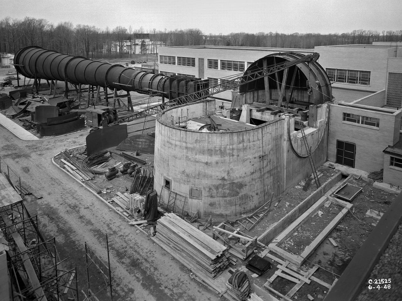
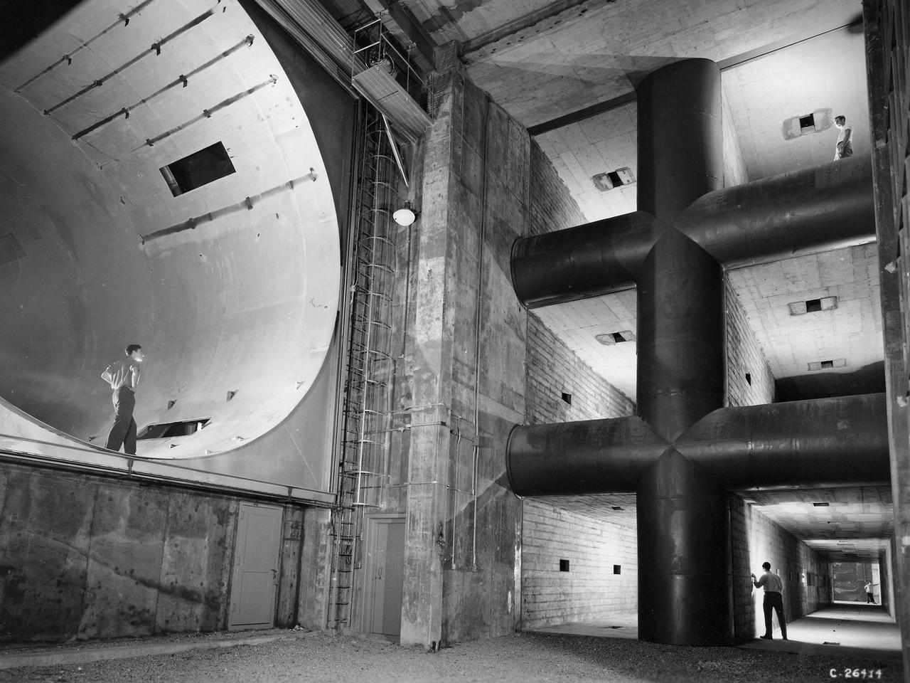
The 8- by 6-Foot Supersonic Wind Tunnel at the National Advisory Committee for Aeronautics (NACA) Lewis Flight Propulsion Laboratory was the nation’s largest supersonic facility when it began operation in April 1949. The emergence of new propulsion technologies such as turbojets, ramjets, and rockets during World War II forced the NACA and the aircraft industry to develop new research tools. In late 1945 the NACA began design work for new large supersonic wind tunnels at its three laboratories. The result was the 4- by 4-Foot Supersonic Wind Tunnel at Langley Memorial Aeronautical Laboratory, 6- by 6-foot supersonic wind tunnel at Ames Aeronautical Laboratory, and the largest facility, the 8- by 6-Foot Supersonic Wind Tunnel in Cleveland. The two former tunnels were to study aerodynamics, while the 8- by 6 facility was designed for supersonic propulsion. The 8- by 6-Foot Supersonic Wind Tunnel was used to study propulsion systems, including inlets and exit nozzles, combustion fuel injectors, flame holders, exit nozzles, and controls on ramjet and turbojet engines. Flexible sidewalls alter the tunnel’s nozzle shape to vary the Mach number during operation. A seven-stage axial compressor, driven by three electric motors that yield a total of 87,000 horsepower, generates air speeds from Mach 0.36 to 2.0. A section of the tunnel is seen being erected in this photograph.
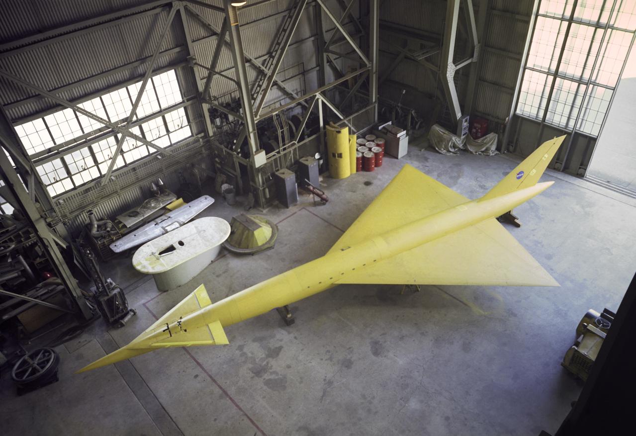
Supersonic transport model test in 40x80 foot wind tunnel, 3/4 overhead view of model in shop floor. 04/06/1961 R 975 T
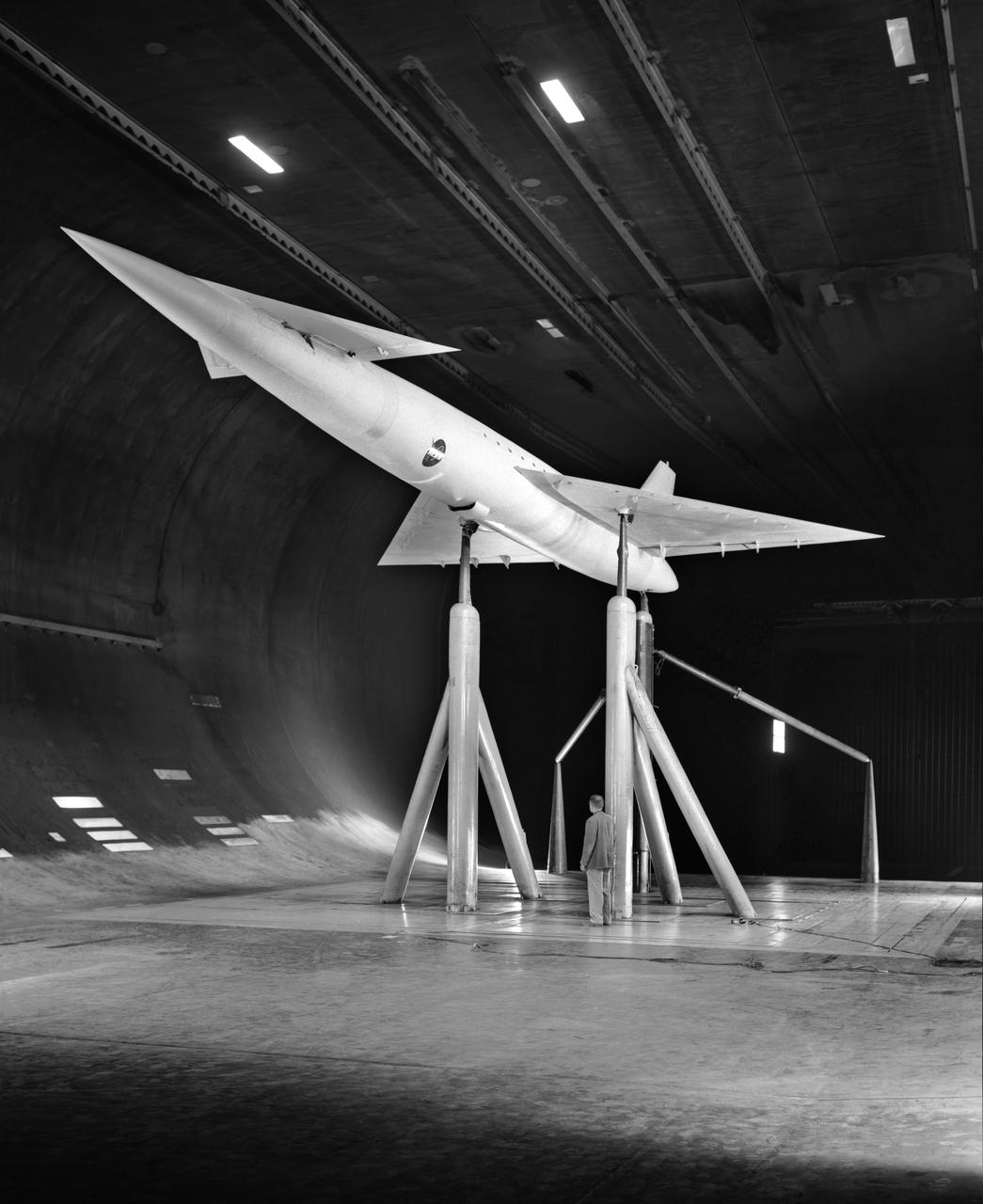
Low Speed investigation of a supersonic transport model with delta wing and delta conard, in the 40x80 Wind Tunnel. R 975 T Zero angel of attack. 3/4 rear view from below.
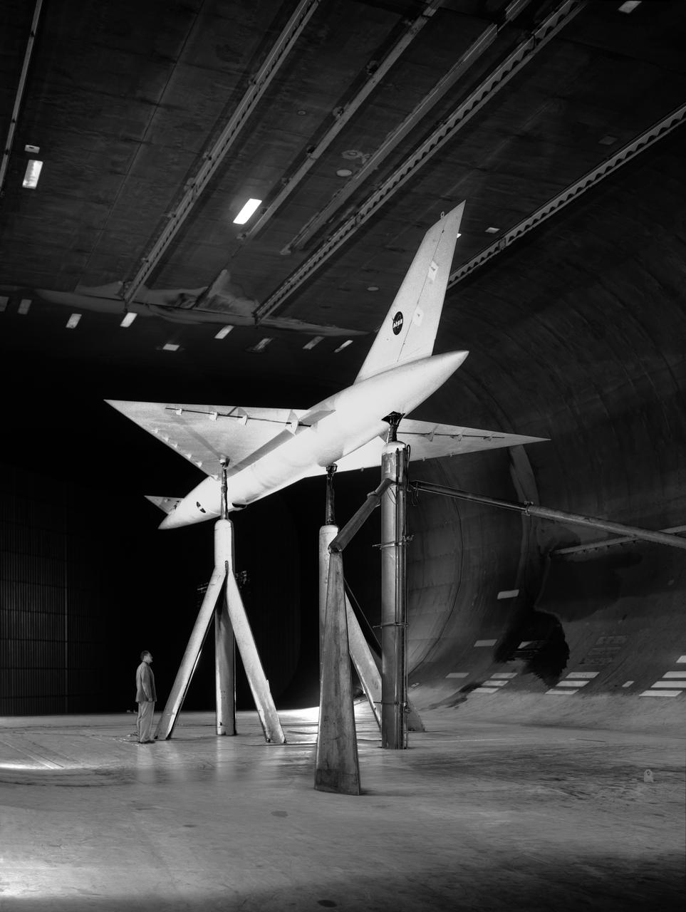
Low Speed investigation of a supersonic transport model in the 40x80 Wind Tunnel. 03/01/1961 R 975 T Zero angel of attack. Supersonic transport with delta wing and delta conard. 3/4 front view.
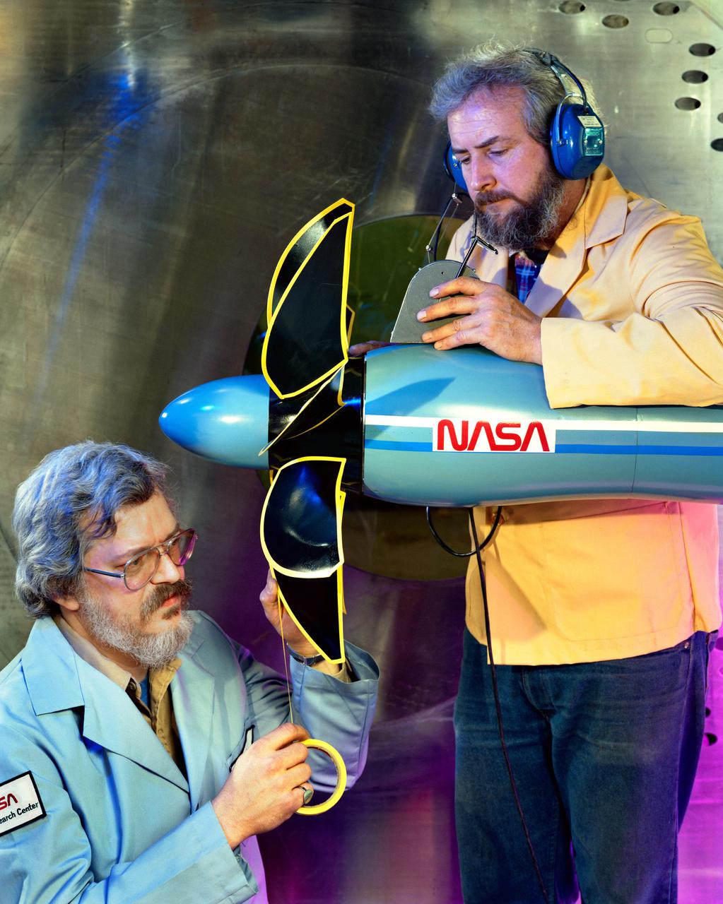
Technicians ready a single rotating propeller model in the 8x6 Supersonic Wind Tunnel
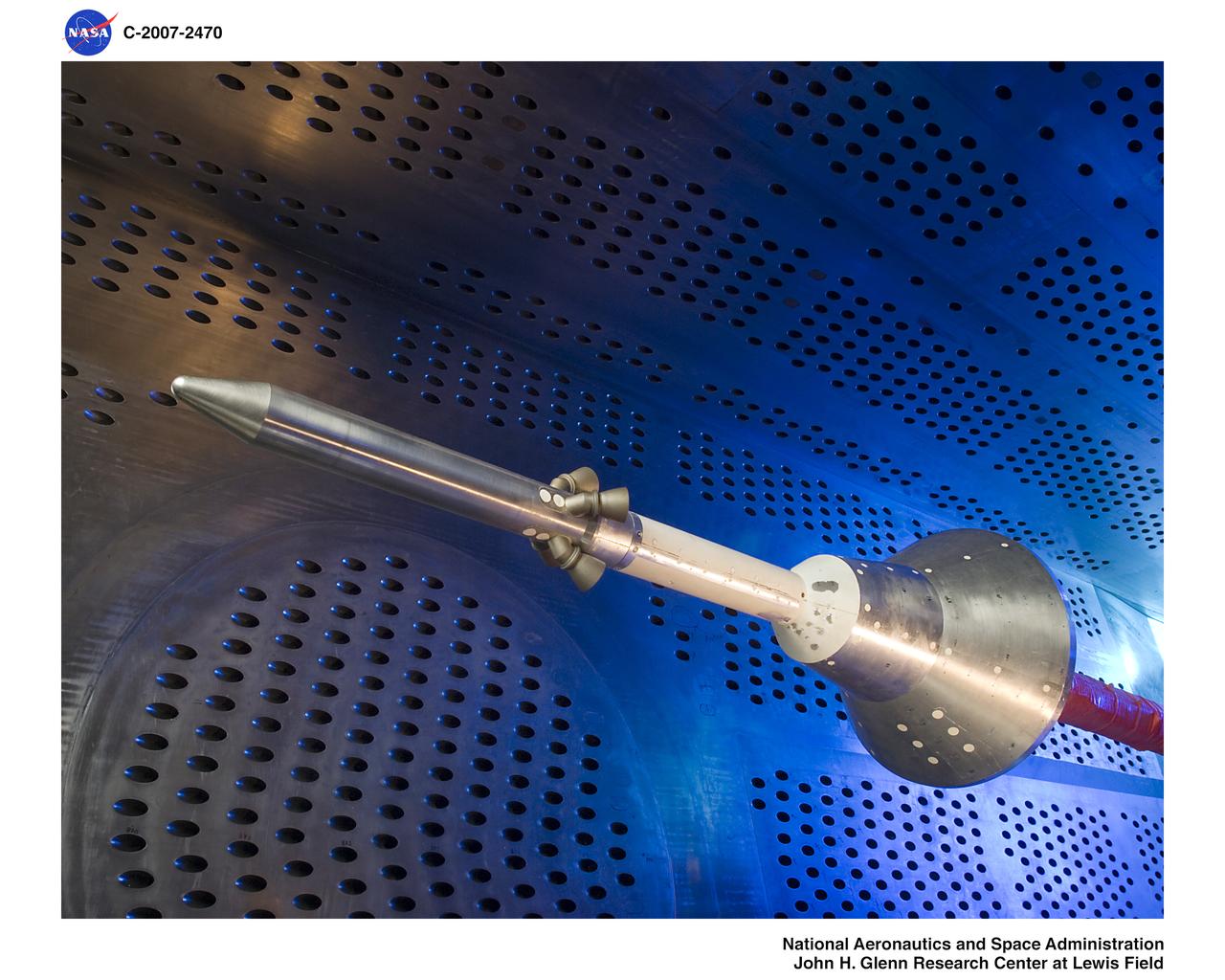
Orion Capsule and Launch Abort System (LAS) installed in the NASA Glenn 8x6 Supersonic Wind Tunnel (SWT) for testing. This test is an Aero Acoustic test of the LAS. 8x6 supersonic wind tunnel test section
The 10- by 10-Foot Supersonic Wind Tunnel (10×10) is the largest and fastest wind tunnel facility at NASA’s Glenn Research Center and is specifically designed to test supersonic propulsion components from inlets and nozzles to full-scale jet and rocket engines.
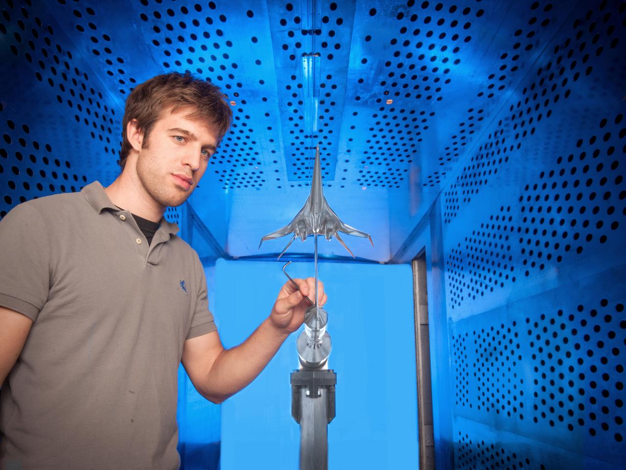
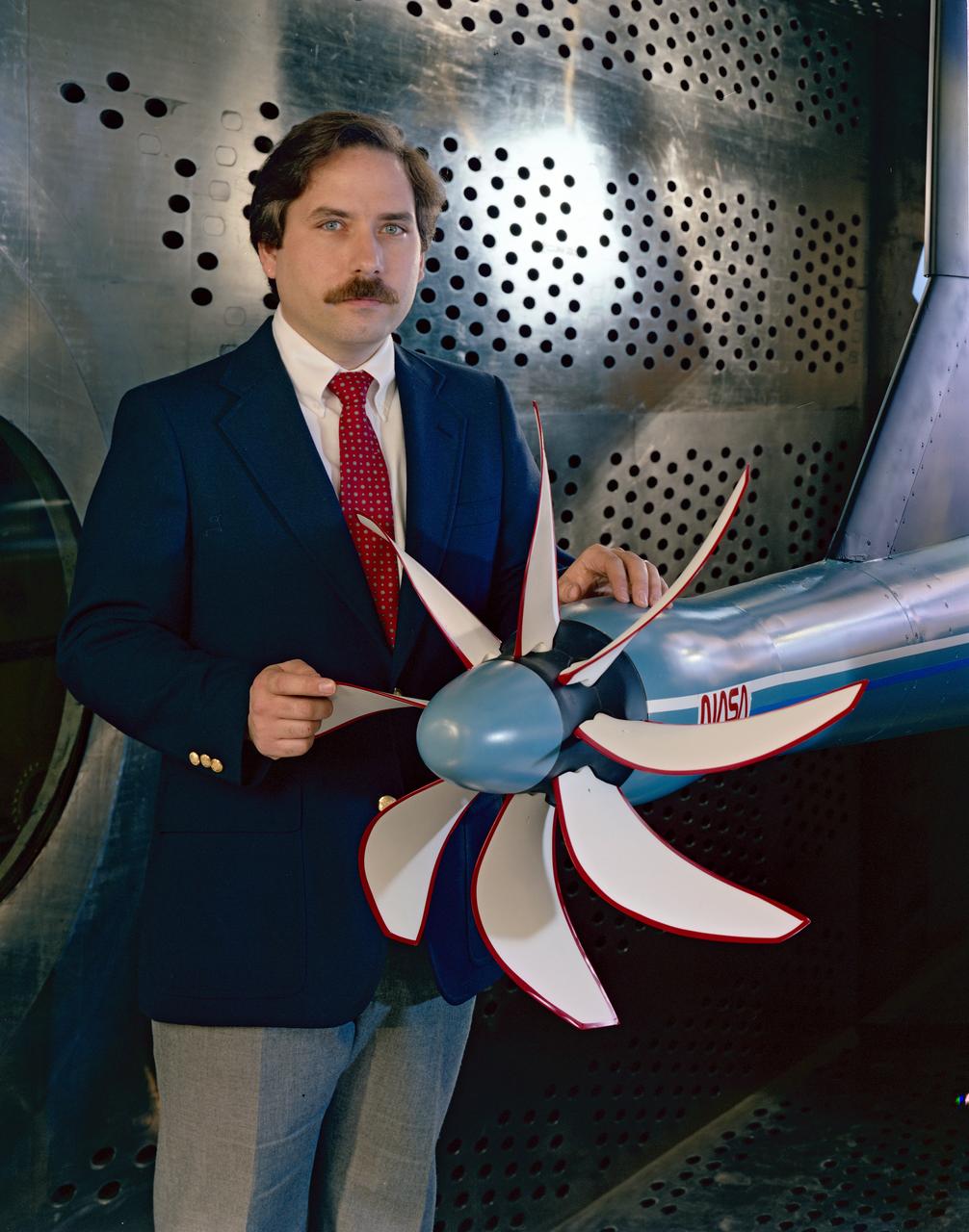
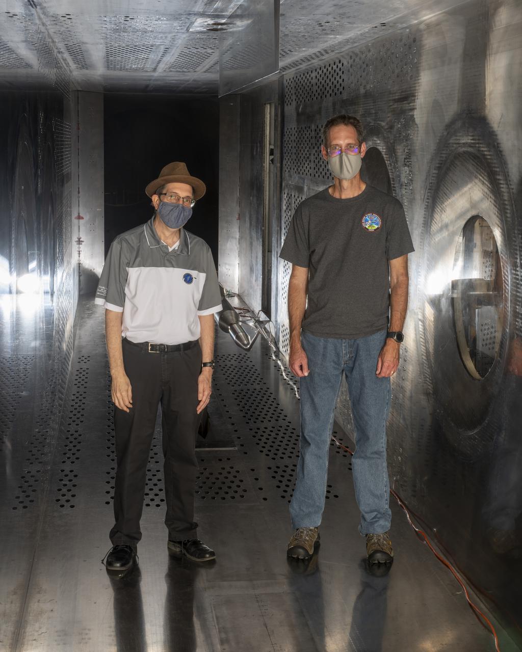
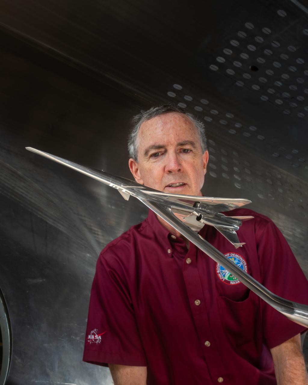
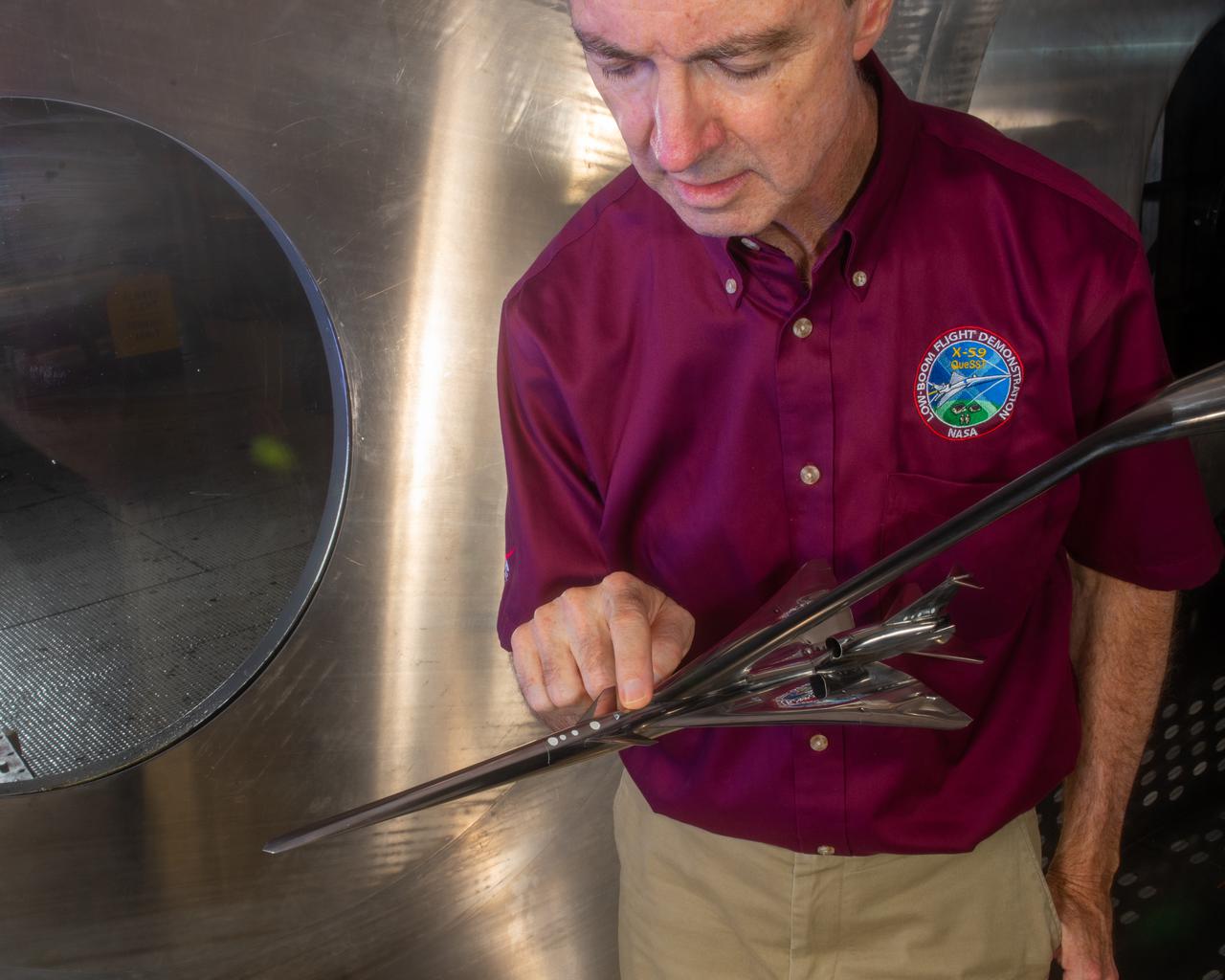
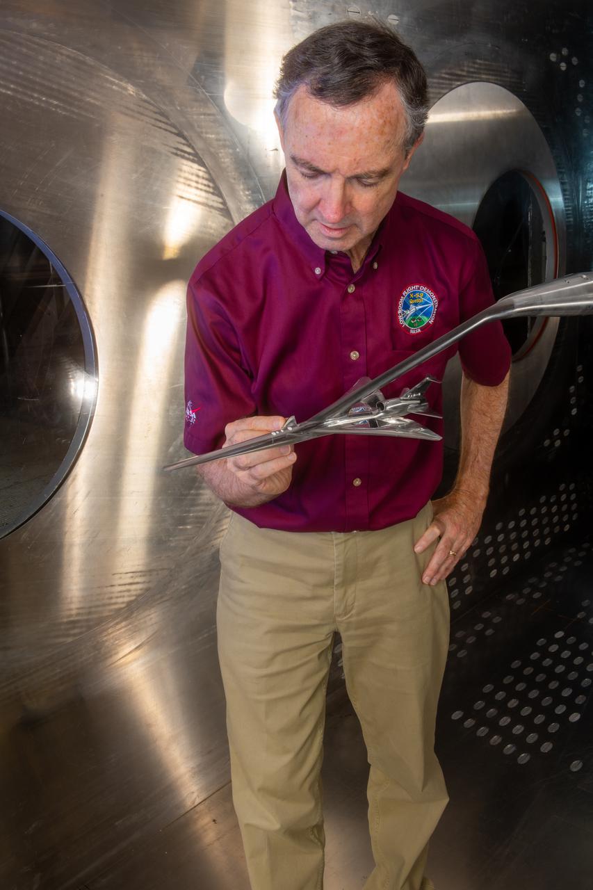
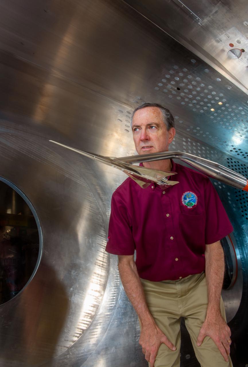
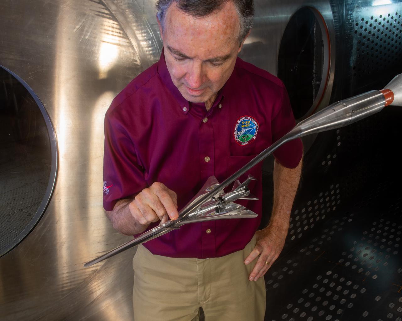
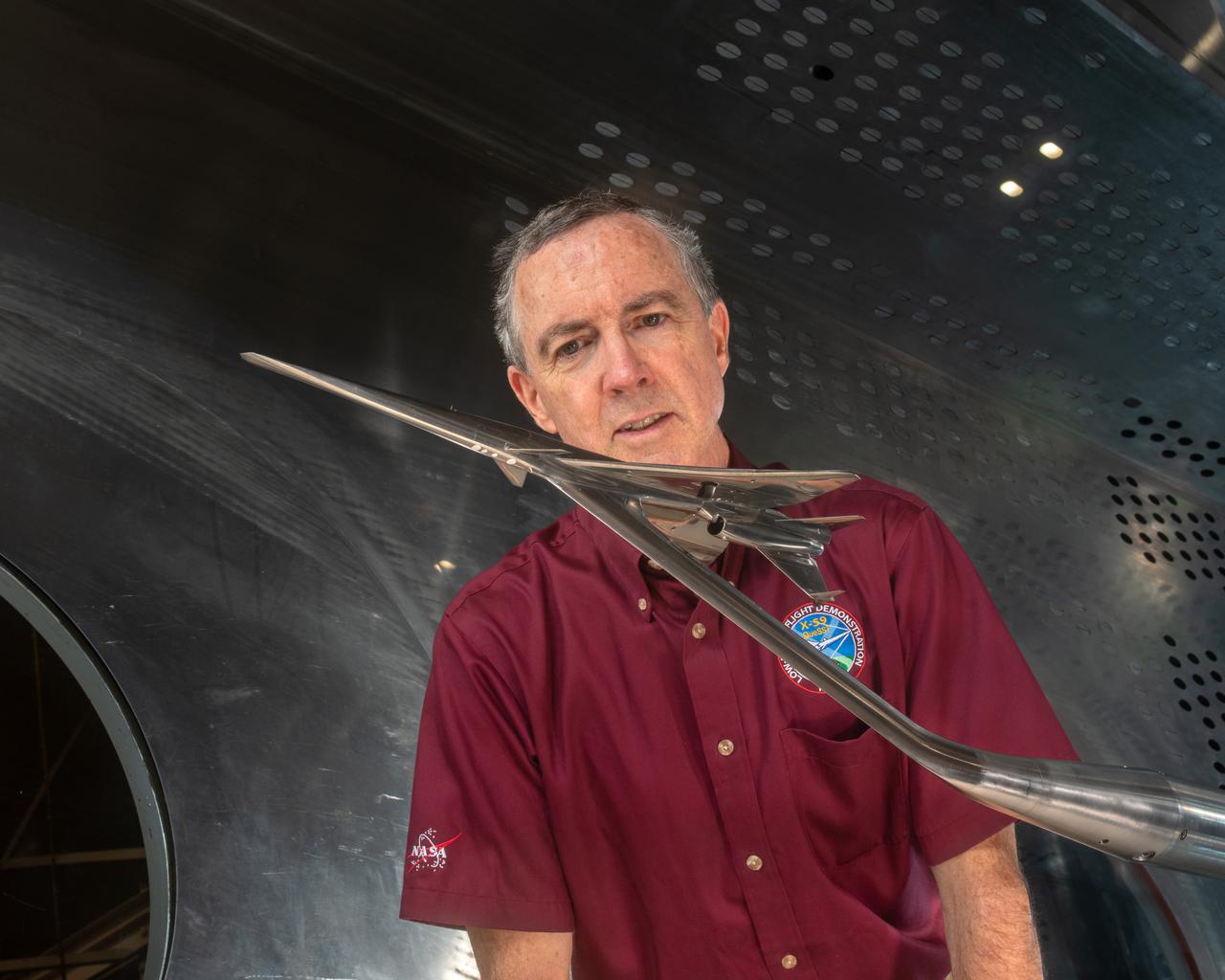
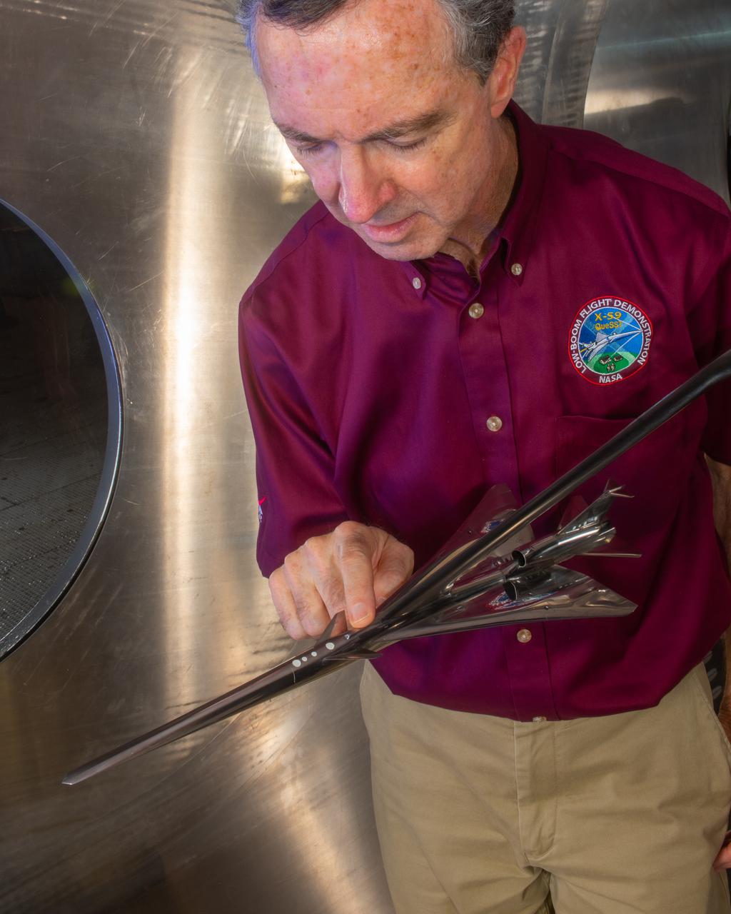
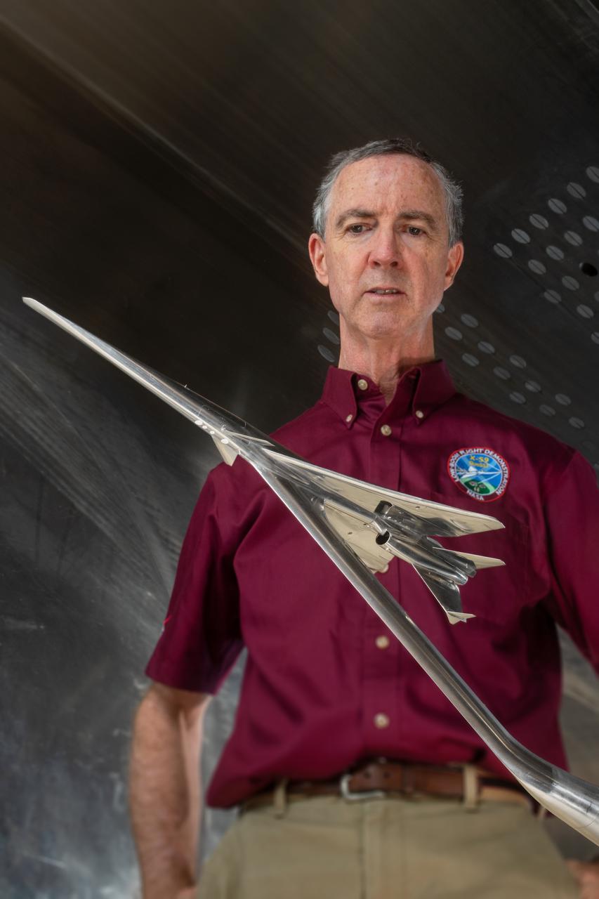
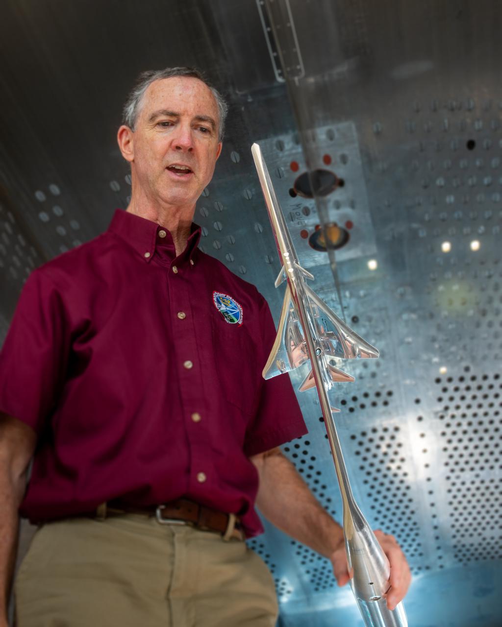
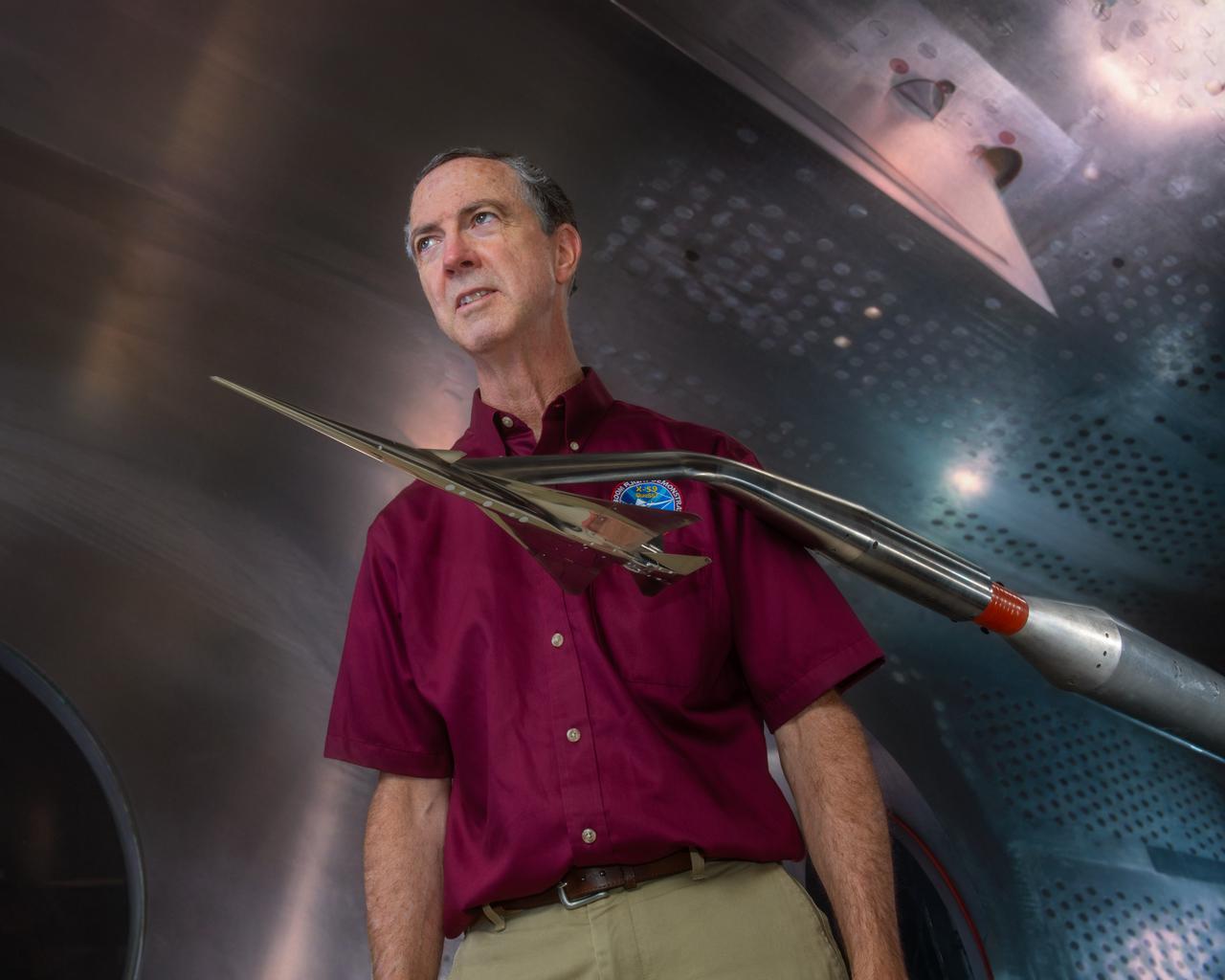
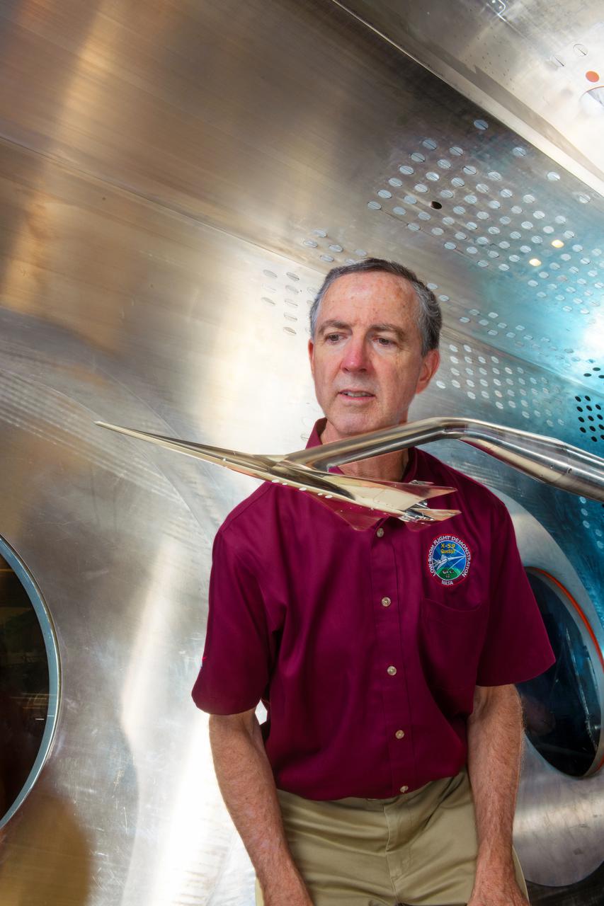
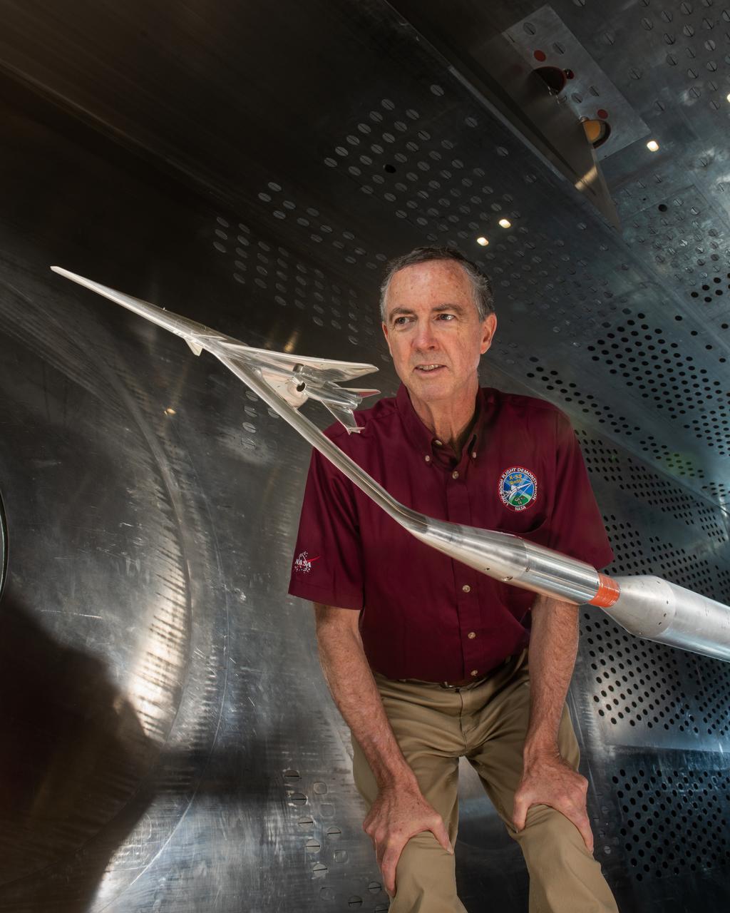
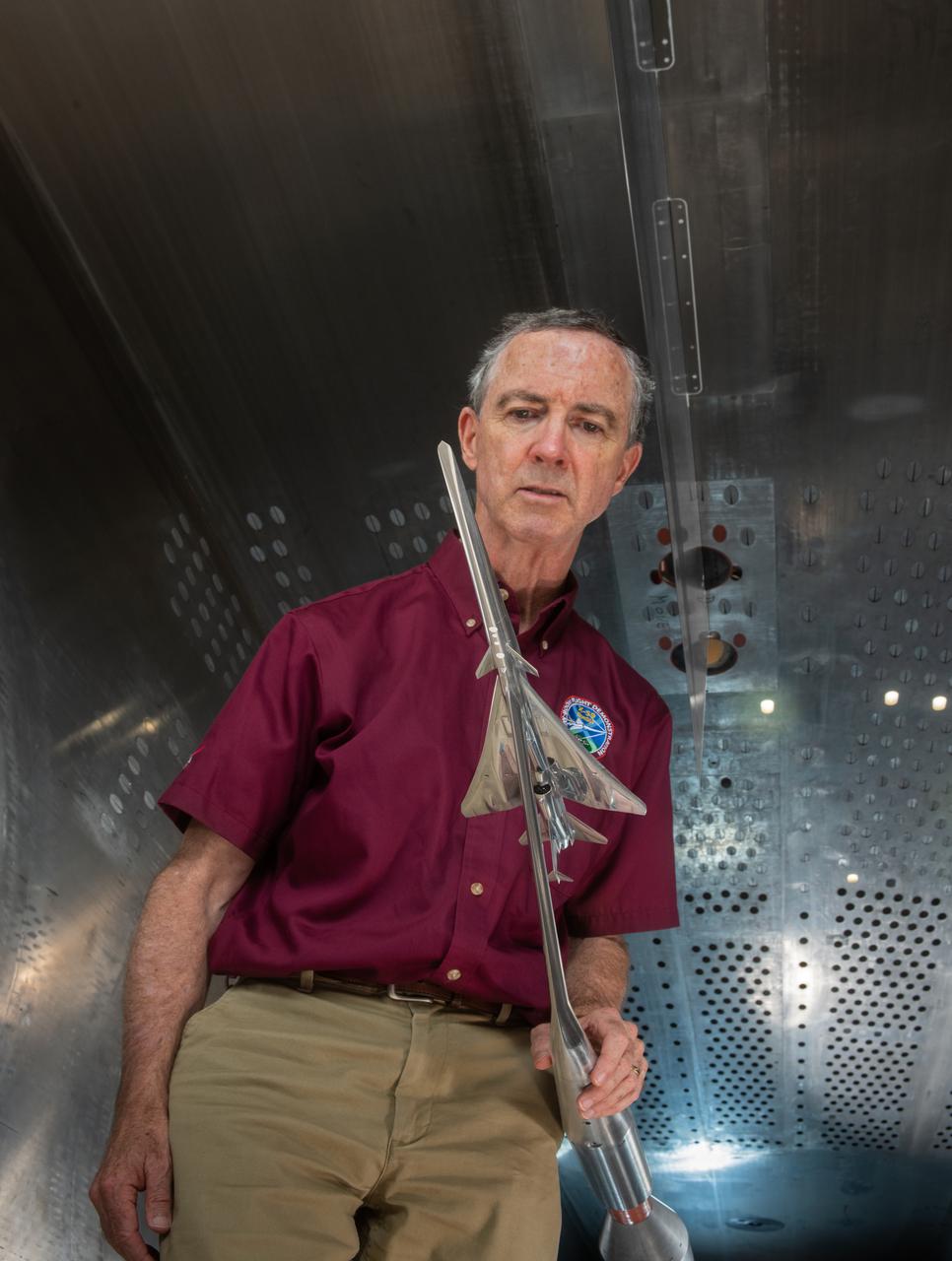
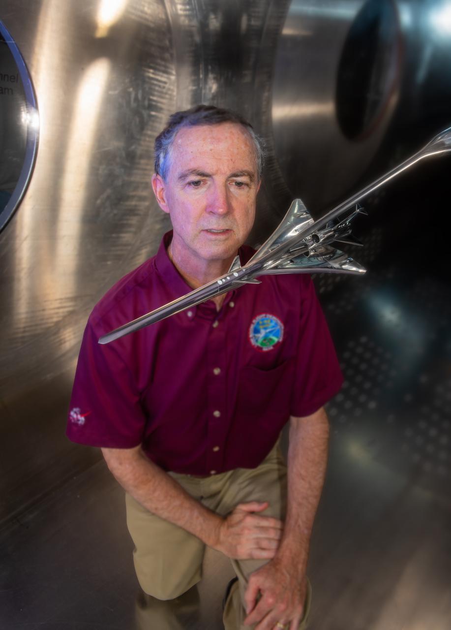
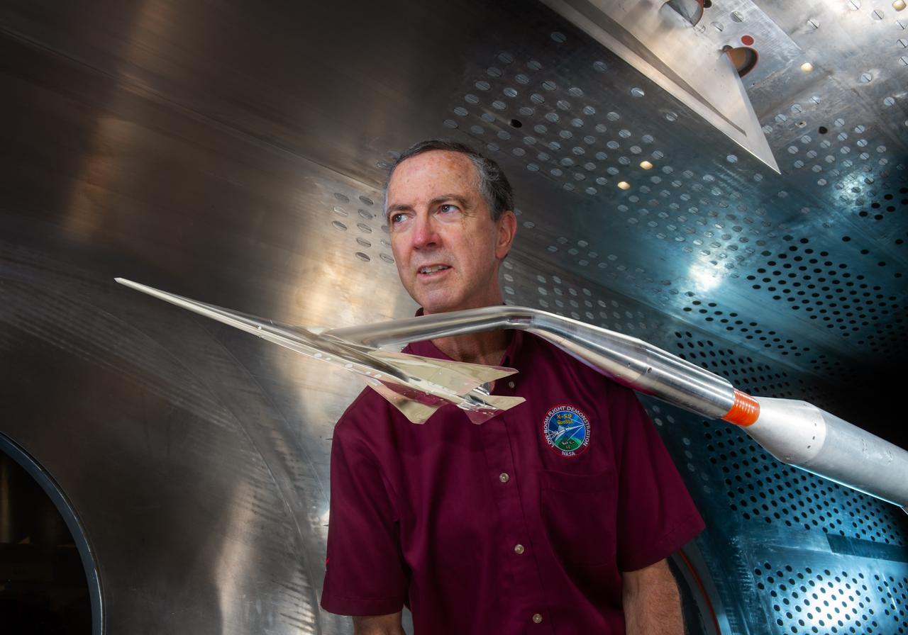
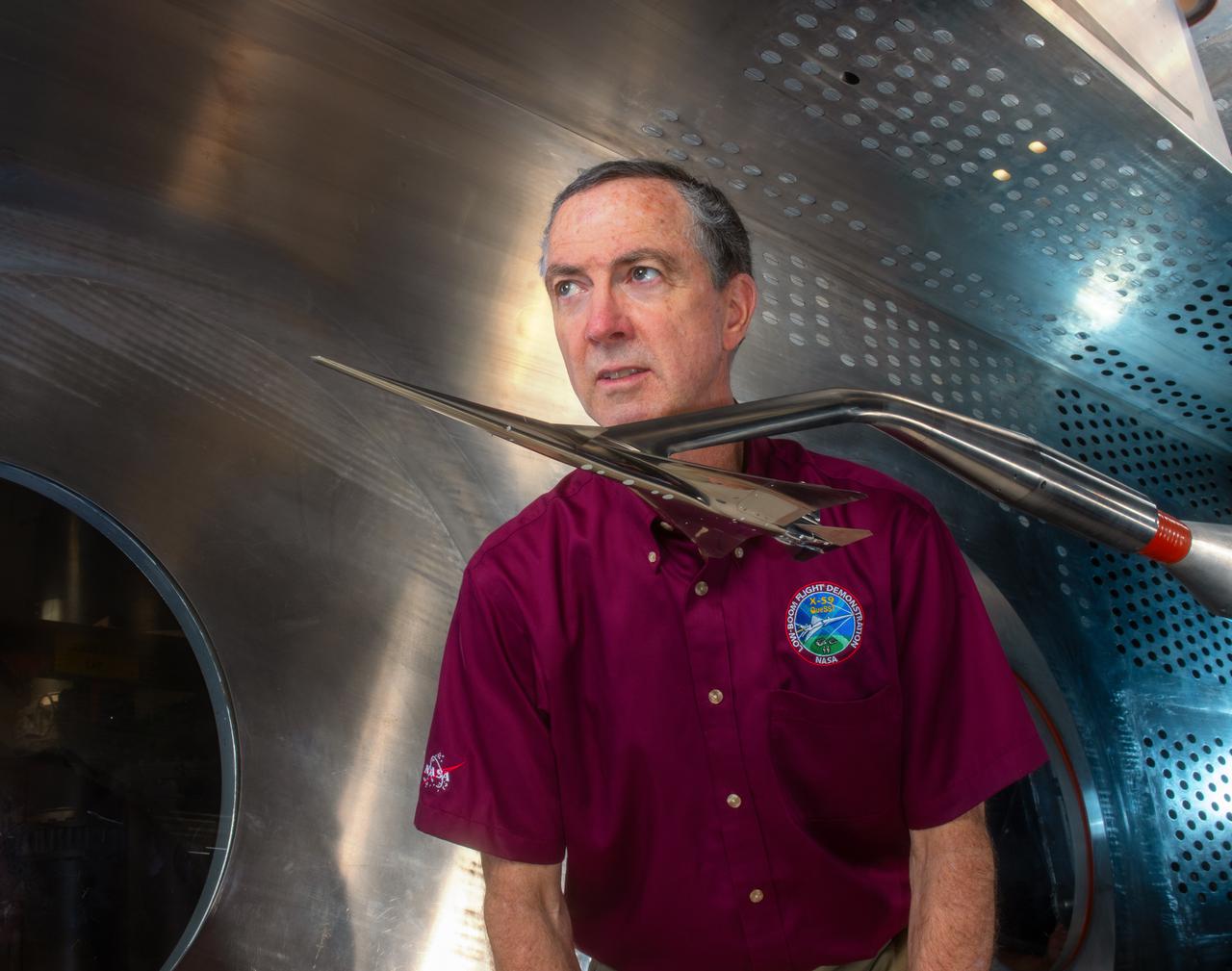
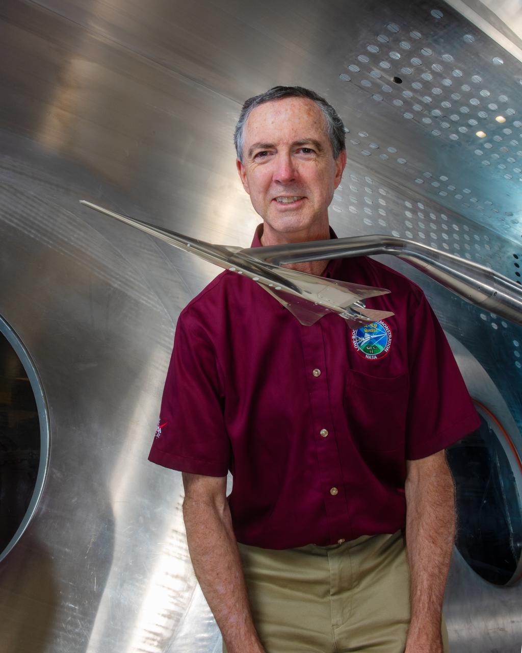
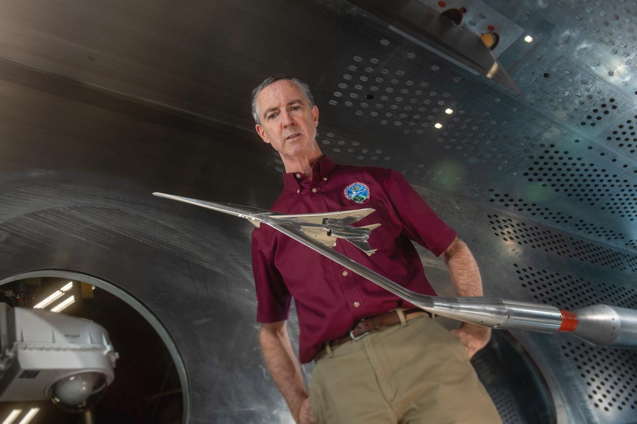
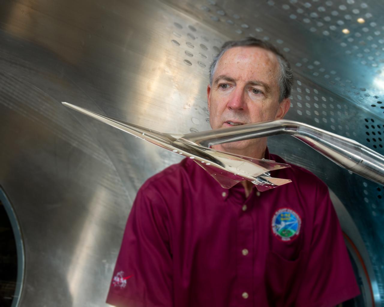
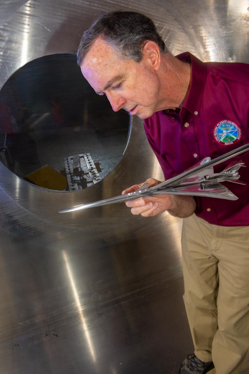
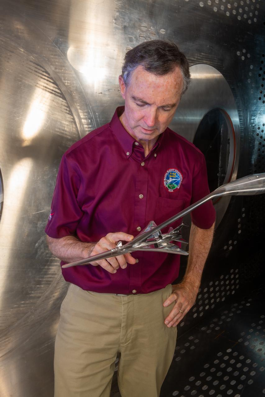
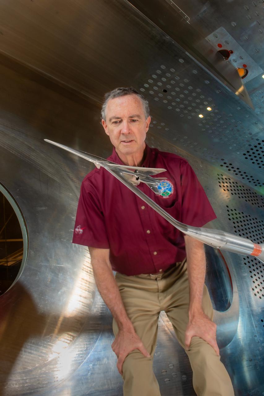
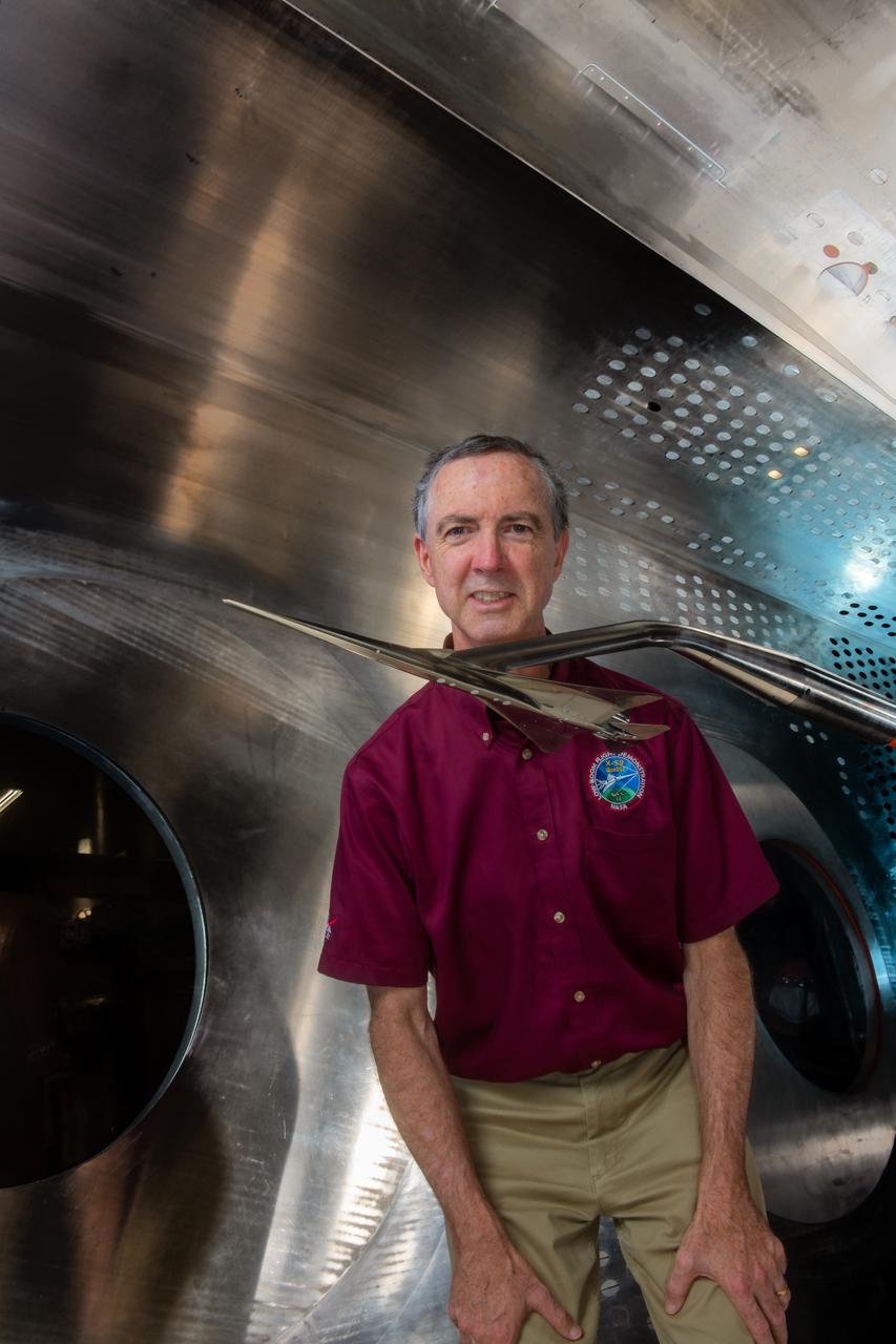
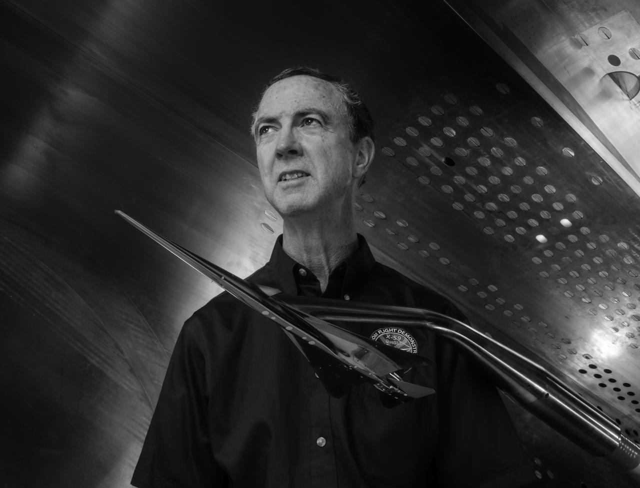
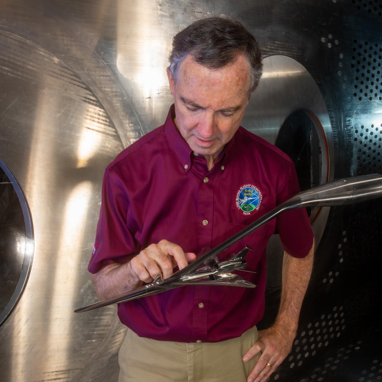
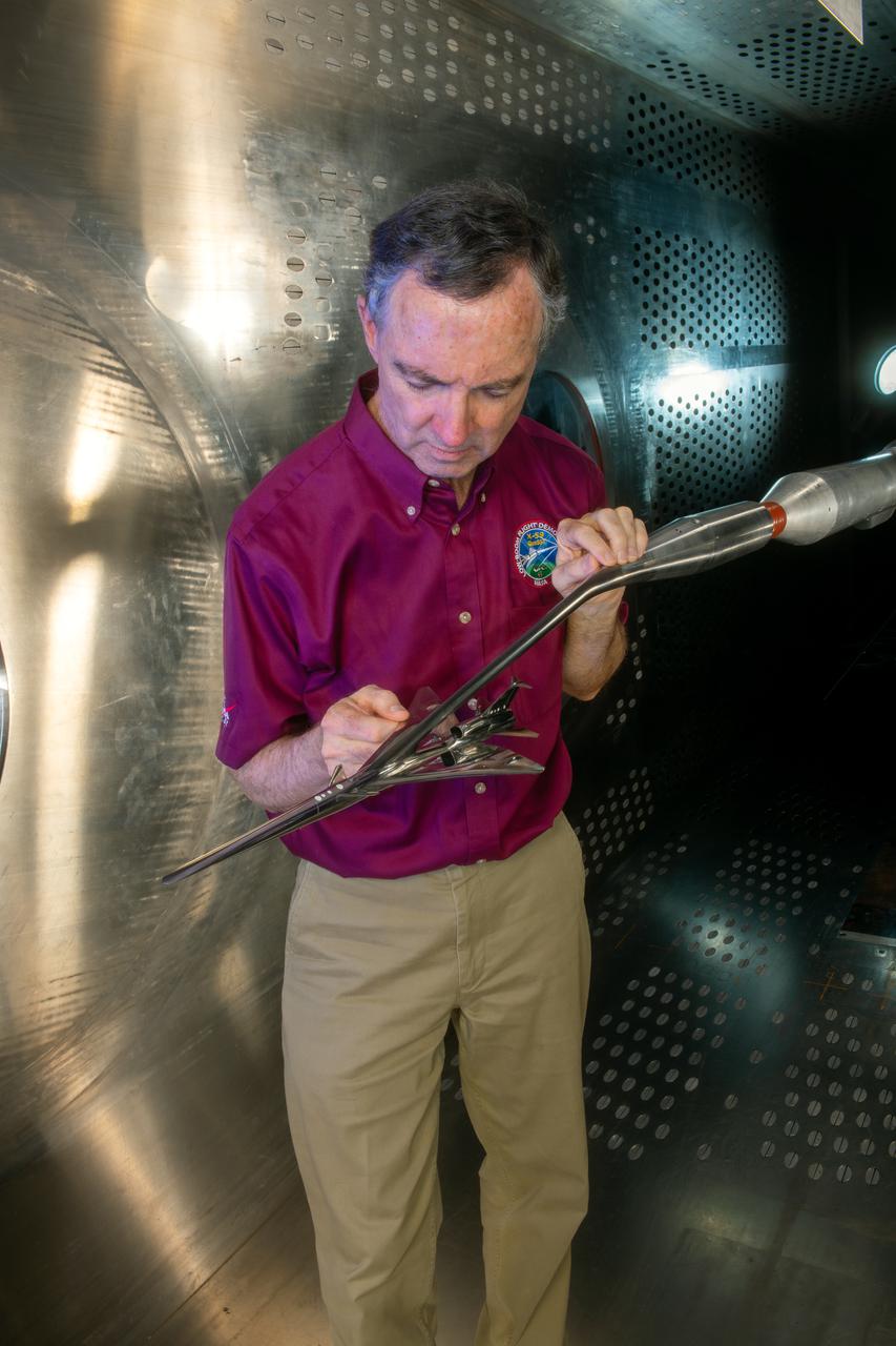
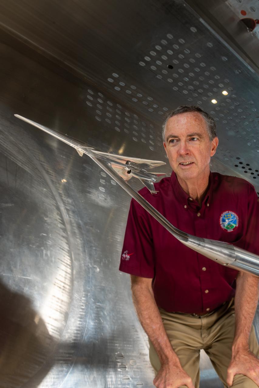
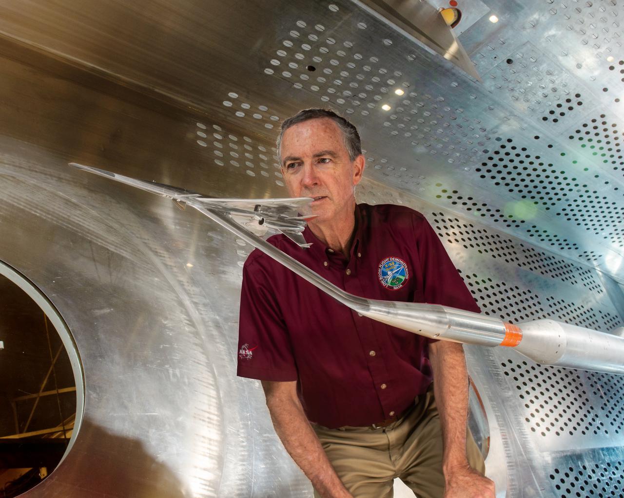
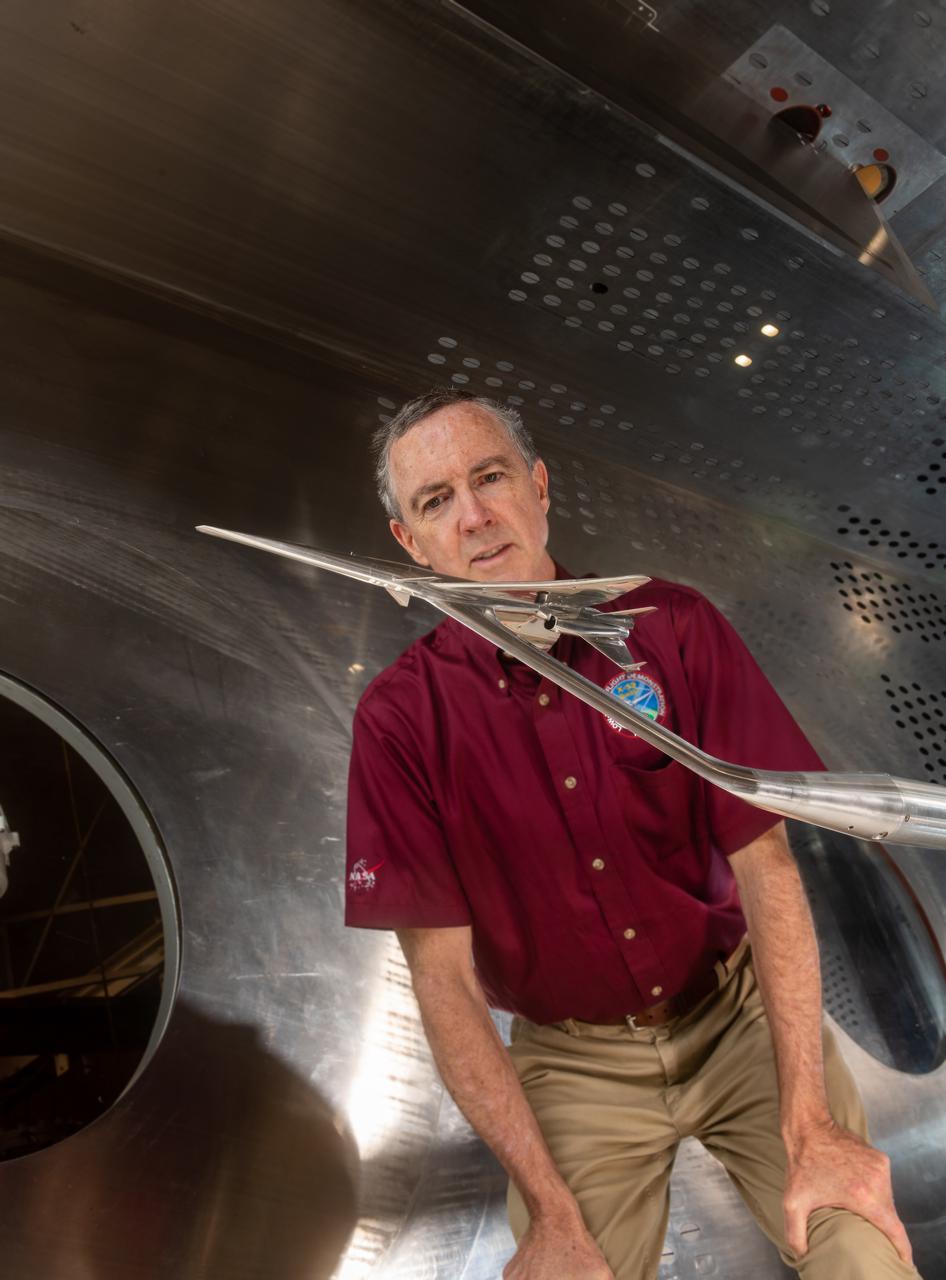
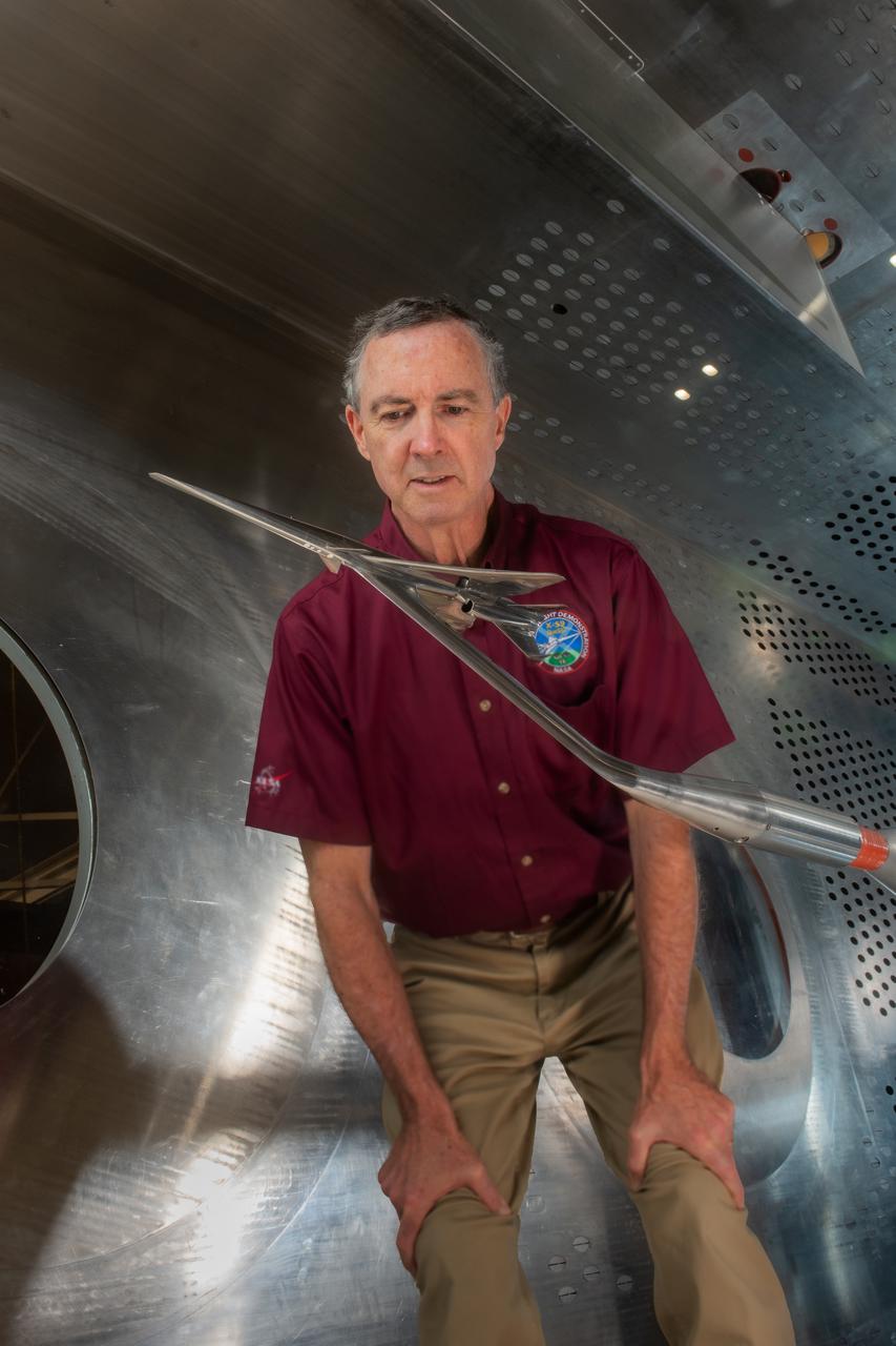
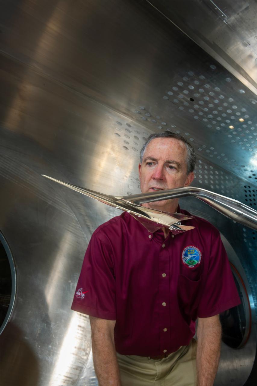
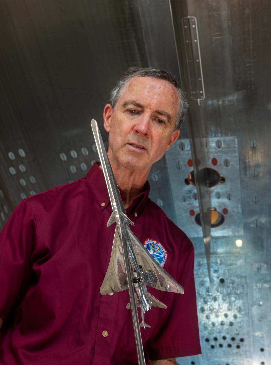
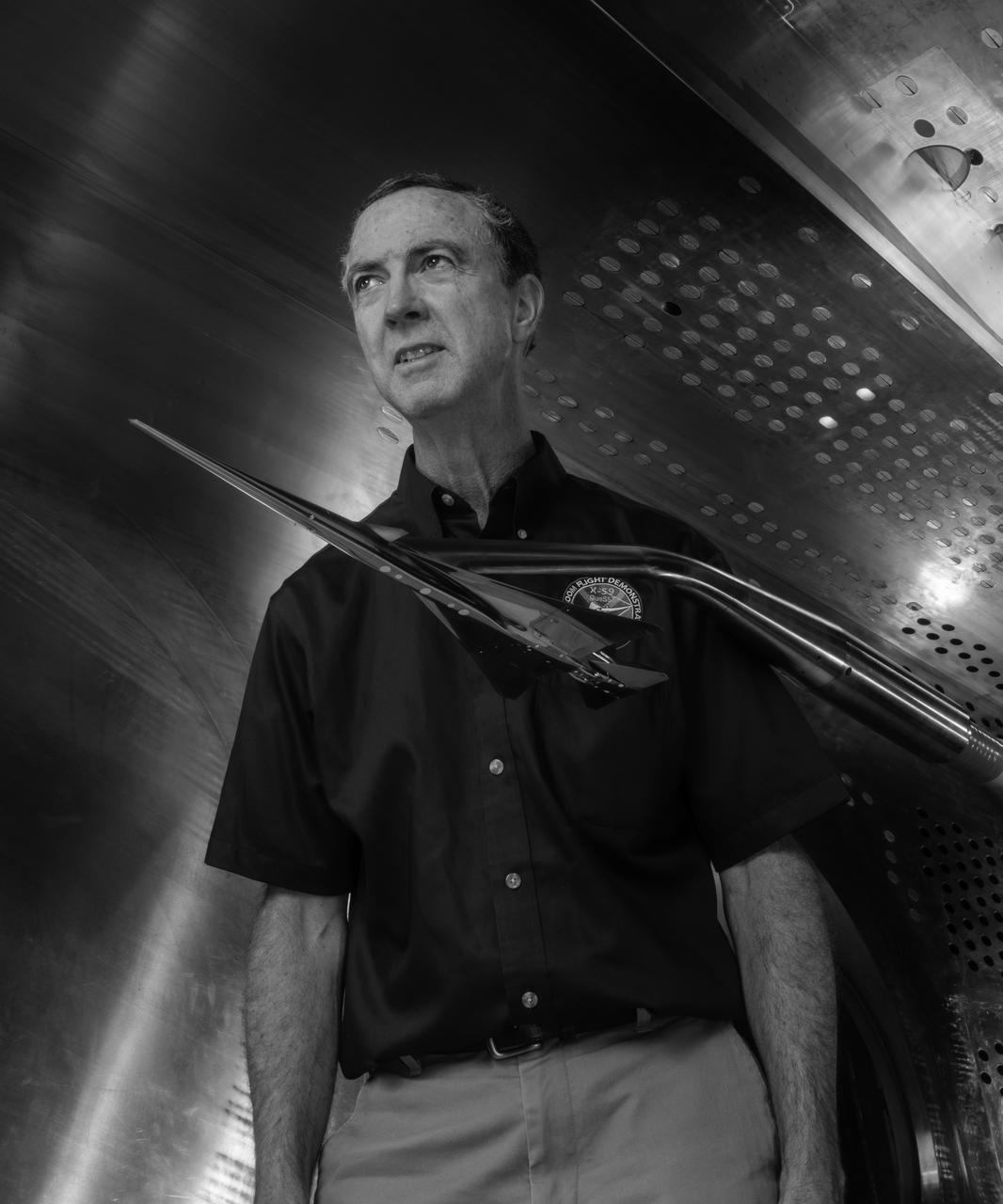
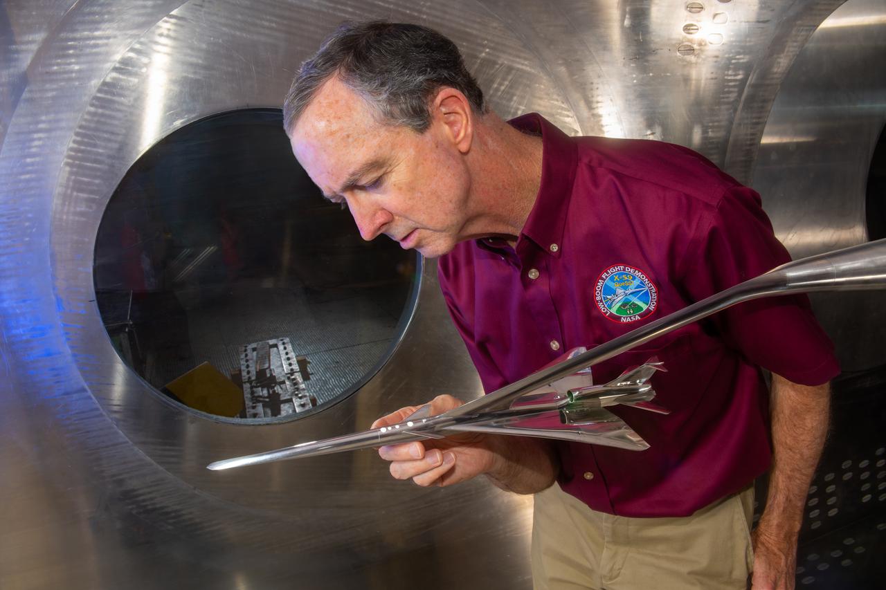
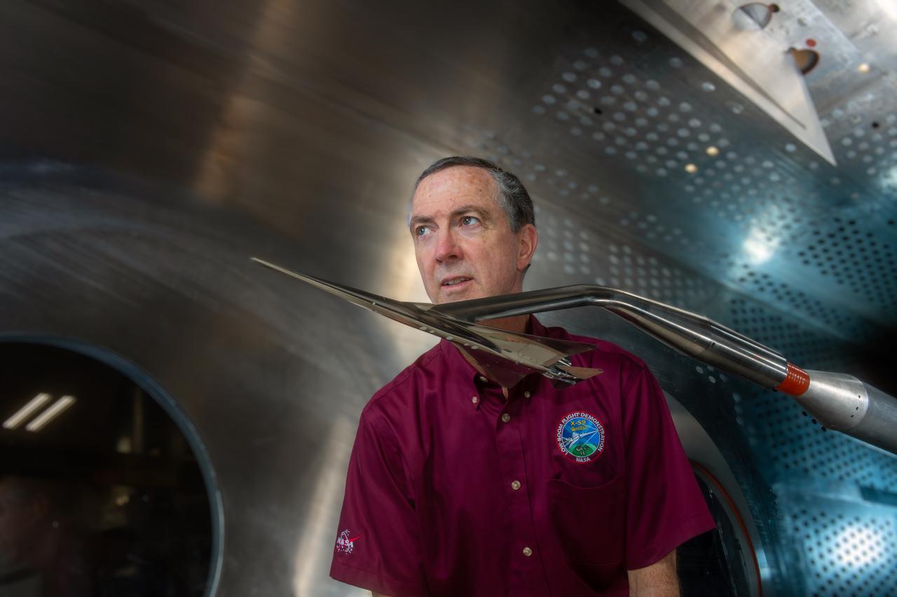
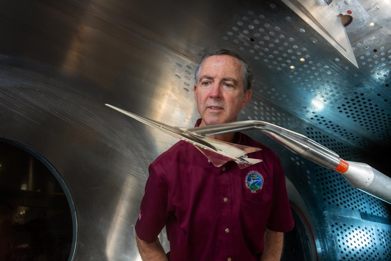
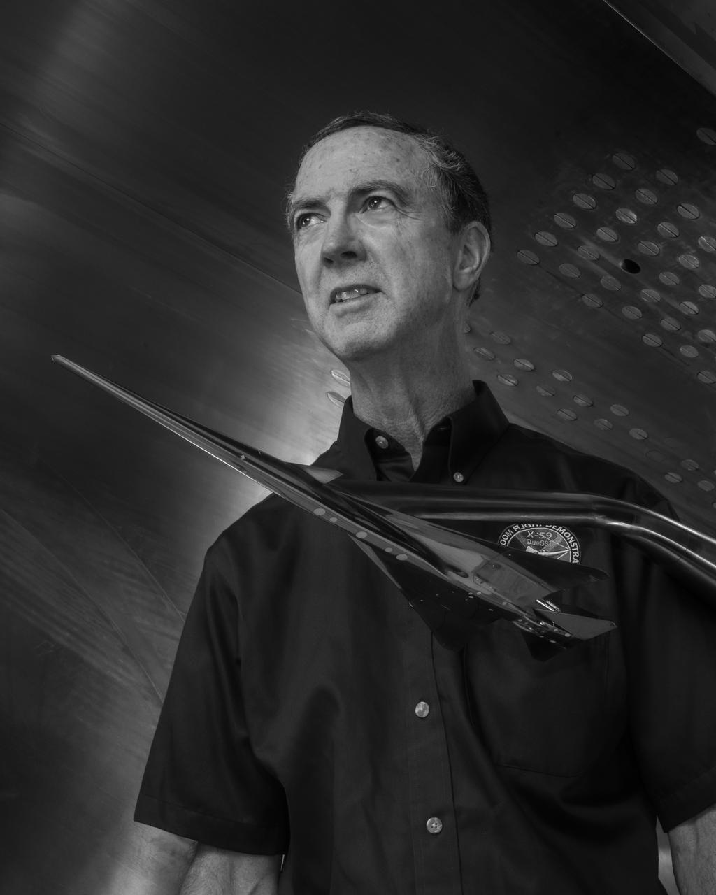
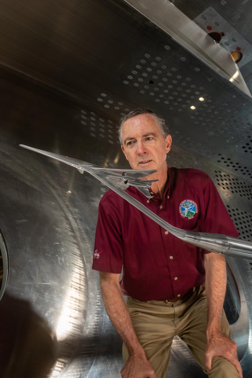
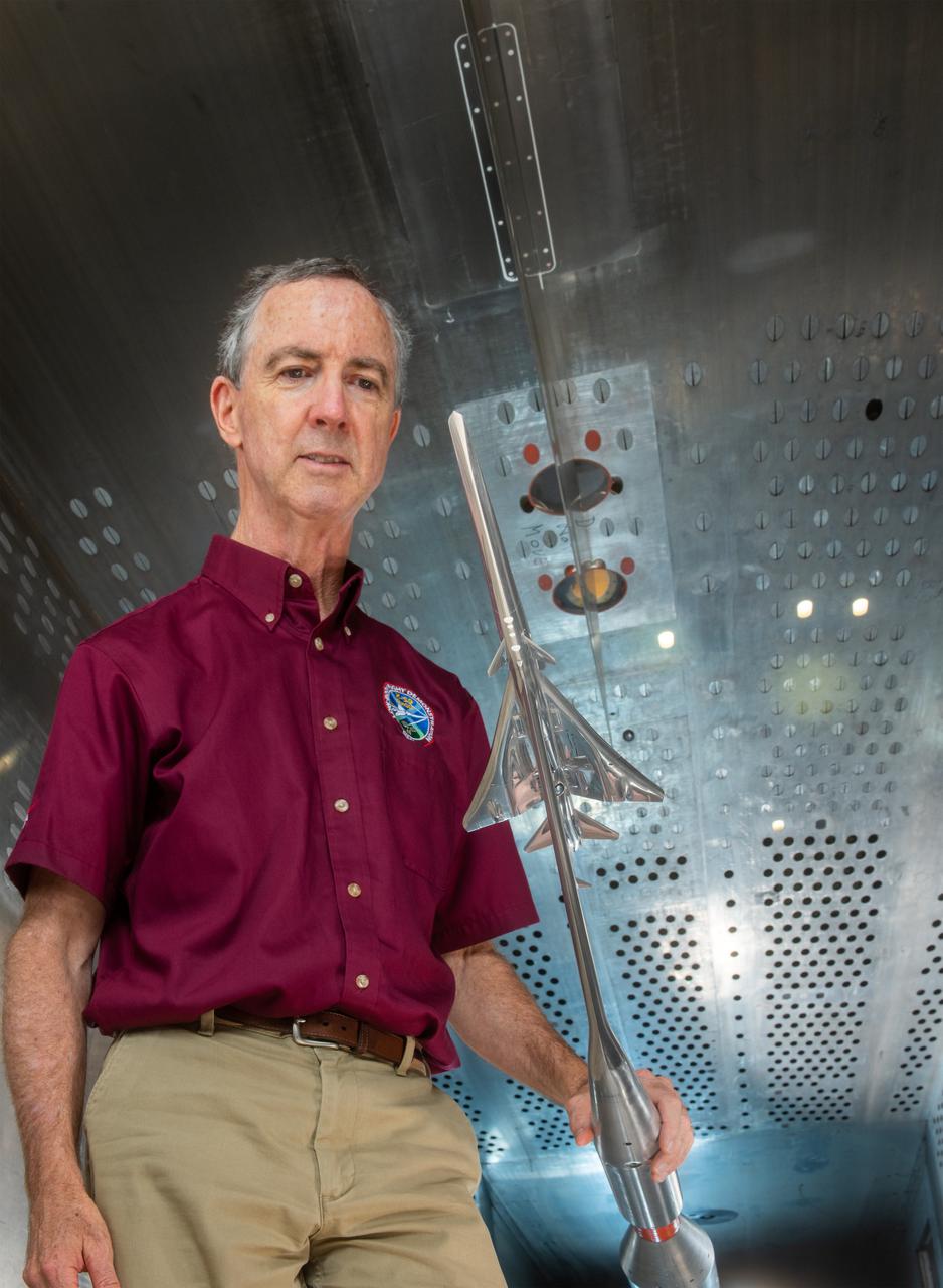
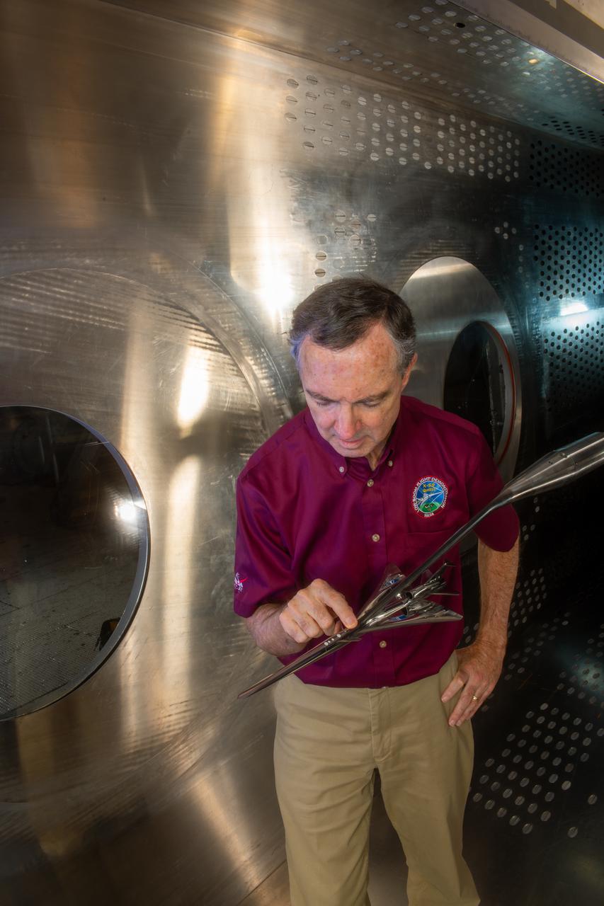
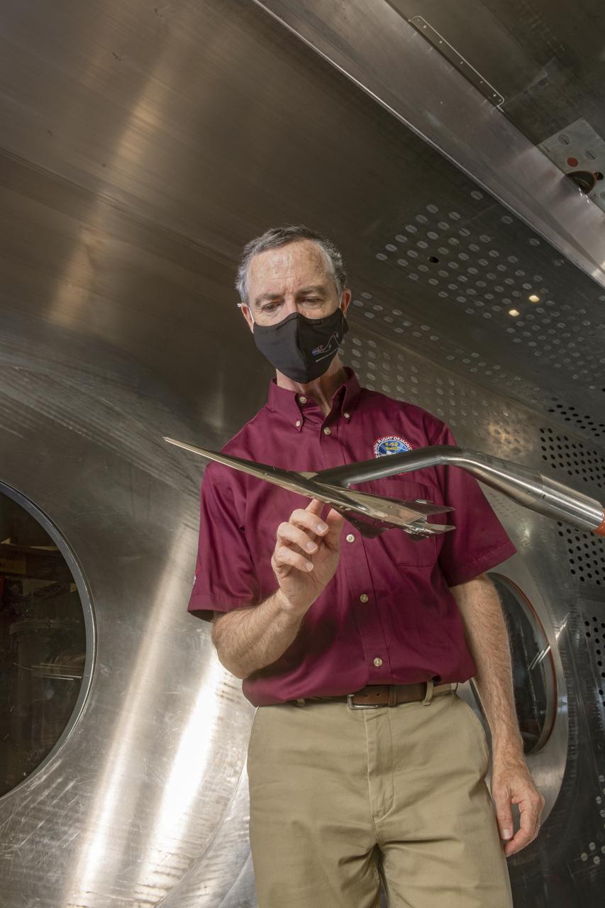
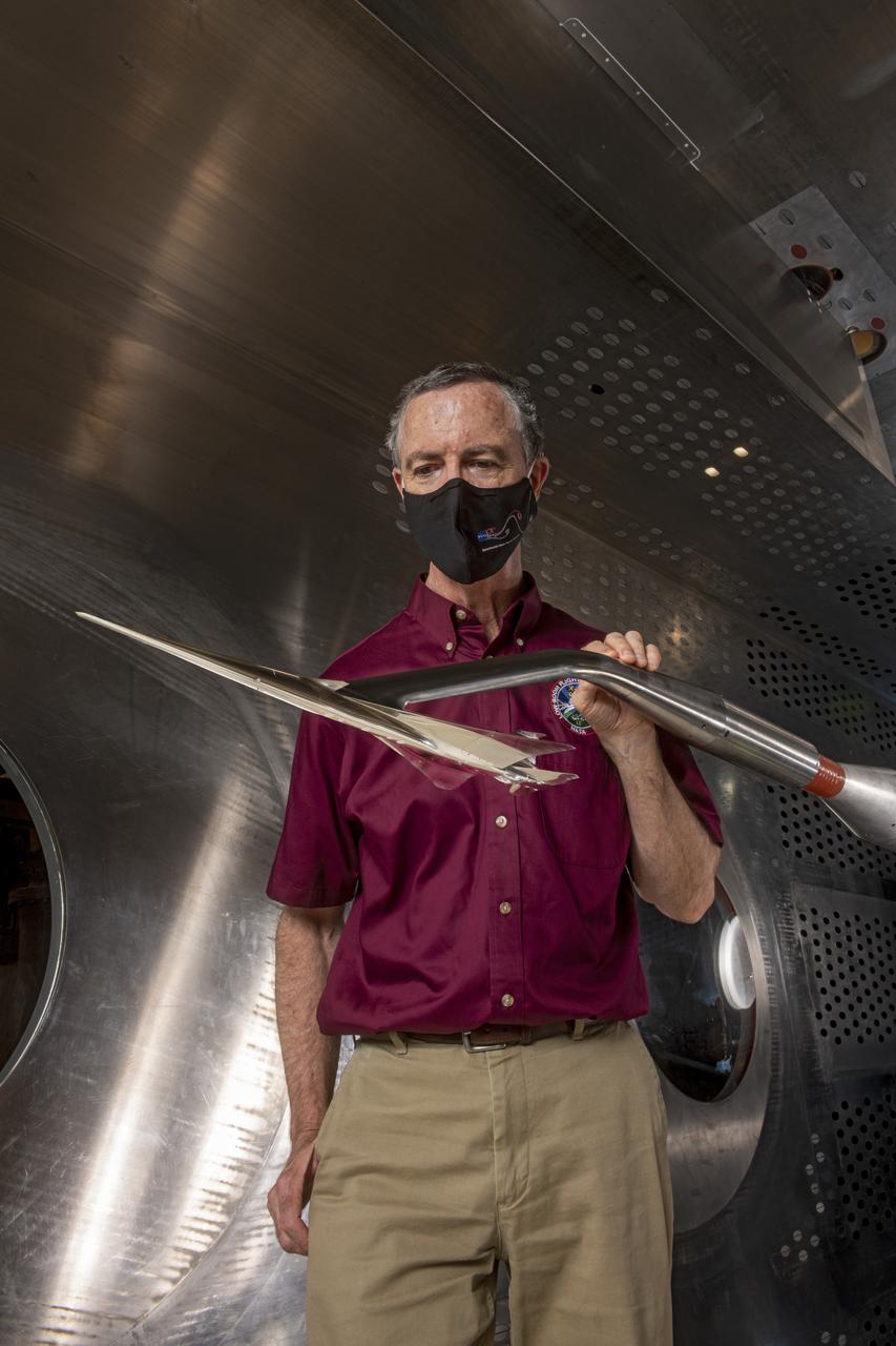
NASA Glenn engineer Gary Williamson with a small model of a future low-boom supersonic aircraft used for testing in the 8' x 6' Supersonic Wind Tunnel at NASA Glenn Research Center.
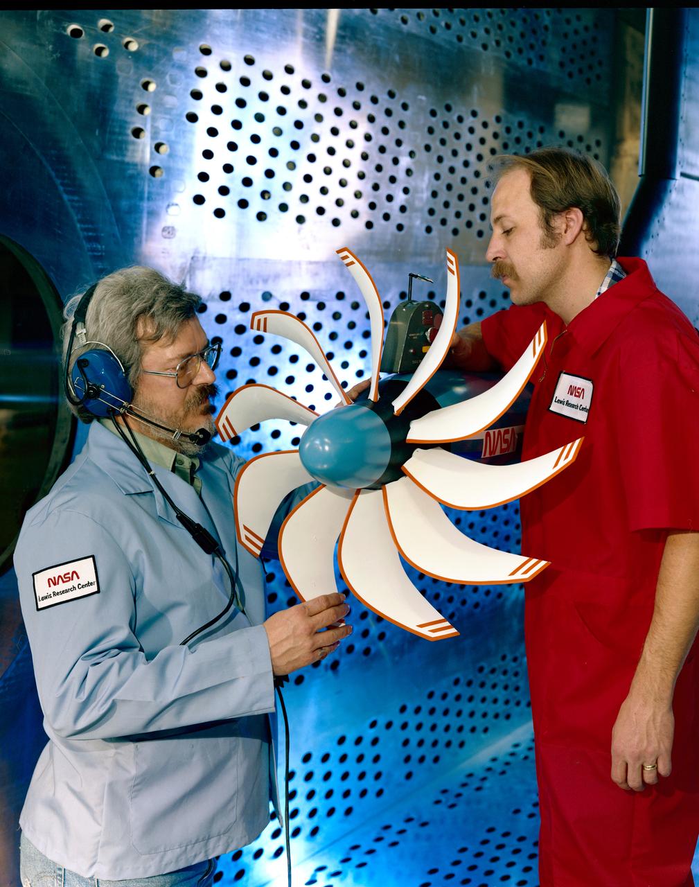
SR-3 Advanced Turboprop (Propfan) in 8x6 foot Supersonic Wind Tunnel
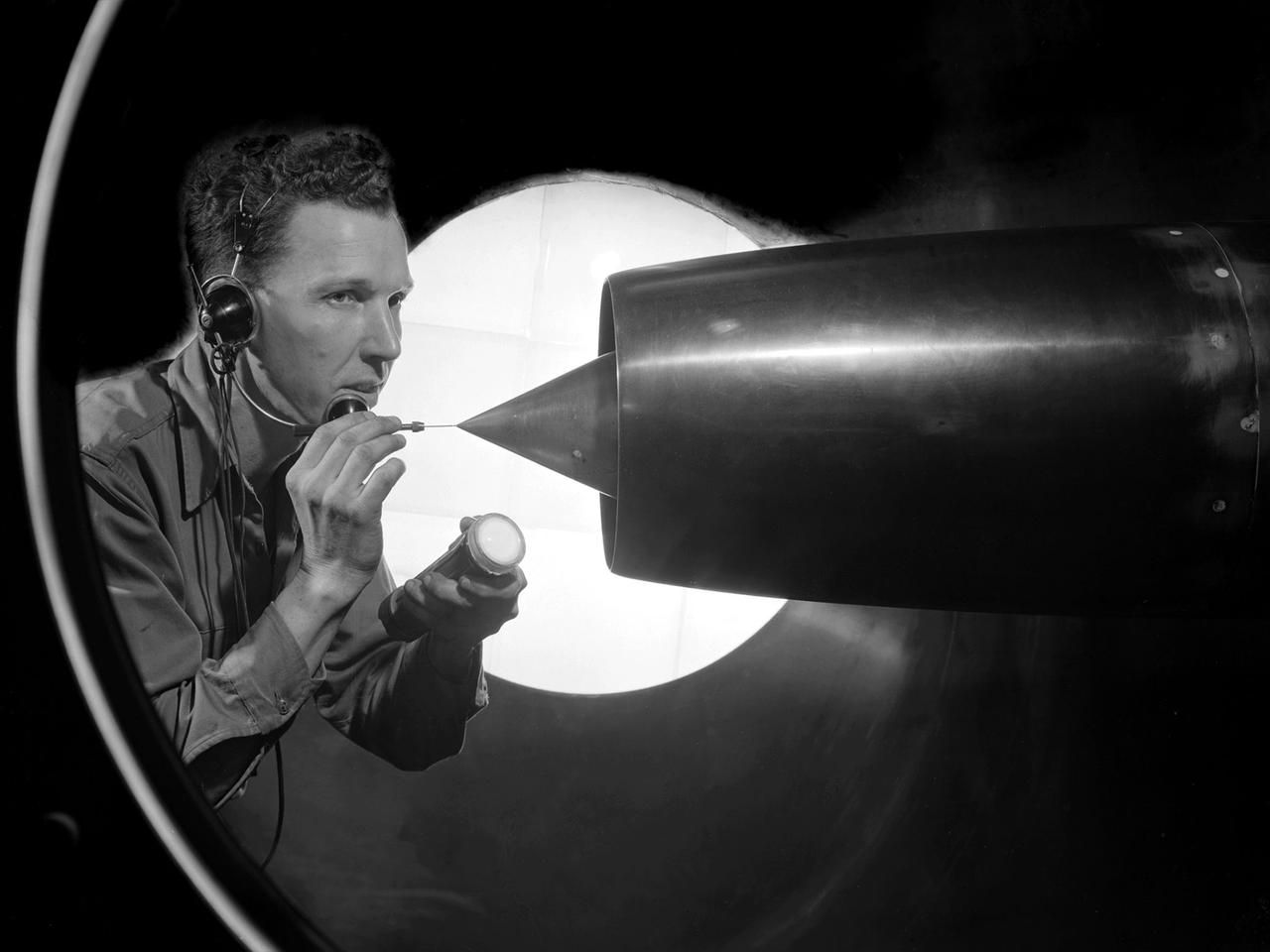
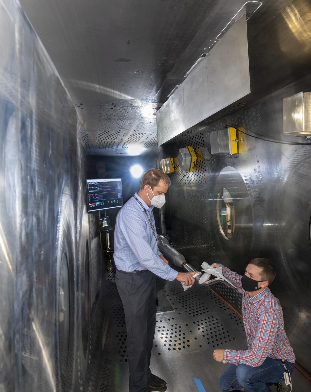
A technician at the National Advisory Committee for Aeronautics (NACA) Lewis Flight Propulsion Laboratory cleans the pitot tube on a 16-inch diameter ramjet in the 8- by 6-Foot Supersonic Wind Tunnel. Pitot tubes are a measurement device used to determine the flow velocity at a specific location in the air stream, not the average velocity of the entire wind stream. NACA Lewis was in the midst of a multi-year program to determine the feasibility of ramjets and design improvements that could be employed for all models. The advantage of the ramjet was its ability to process large volumes of combustion air, resulting in the burning of fuel at the optimal stoichiometric temperatures. This was not possible with turbojets. The higher the Mach number, the more efficient the ramjet operated. The 8- by 6 Supersonic Wind Tunnel had been in operation for just over one year when this photograph was taken. The facility was the NACA’s largest supersonic tunnel and the only facility capable of running an engine at supersonic speeds. The 8- by 6 tunnel was also equipped with a Schlieren camera system that captured the air flow gradient as it passes over the test setup. The ramjet tests in the 8- by 6 tunnel complemented the NACA Lewis investigations using aircraft, the Altitude Wind Tunnel and smaller supersonic tunnels. Researchers studied the ramjet’s performance at different speeds and varying angles -of -attack.
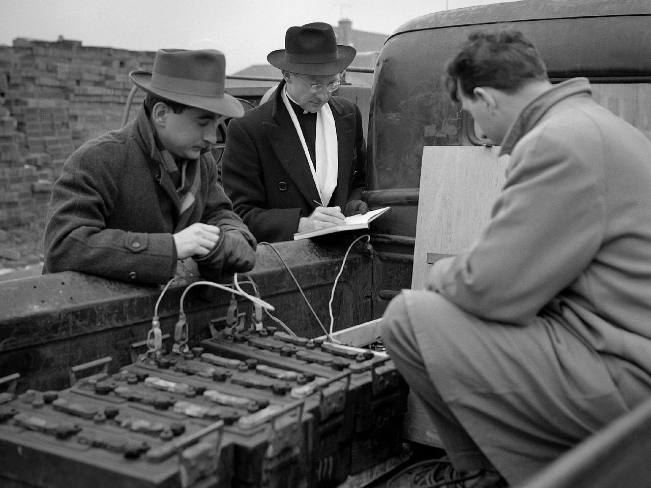
Reverend Henry Birkenhauer and E.F. Carome measure ground vibrations on West 220th Street caused by the operation of the 8- by 6-Foot Supersonic Wind Tunnel at the National Advisory Committee for Aeronautics (NACA) Lewis Flight Propulsion Laboratory. The 8- by 6 was the laboratory’s first large supersonic wind tunnel. It was also the NACA’s most powerful supersonic tunnel, and the NACA’s first facility capable of running an engine at supersonic speeds. The 8- by 6 was originally an open-throat and non-return tunnel. This meant that the supersonic air flow was blown through the test section and out the other end into the atmosphere. Complaints from the local community led to the installation of a muffler at the tunnel exit and the eventual addition of a return leg. Reverend Brikenhauer, a seismologist, and Carome, an electrical technician were brought in from John Carroll University to take vibration measurements during the 8- by 6 tunnel’s first run with a supersonic engine. They found that the majority of the vibrations came from the air and not the ground. The tunnel’s original muffler offered some relief during the facility checkout runs, but it proved inadequate during the operation of an engine in the test section. Tunnel operation was suspended until a new muffler was designed and installed. The NACA researchers, however, were pleased with the tunnel’s operation. They claimed it was the first time a jet engine was operated in an airflow faster than Mach 2.
SR-3 Advanced Turboprop (Propfan) in 8x6 foot Supersonic Wind Tunnel (SWT)

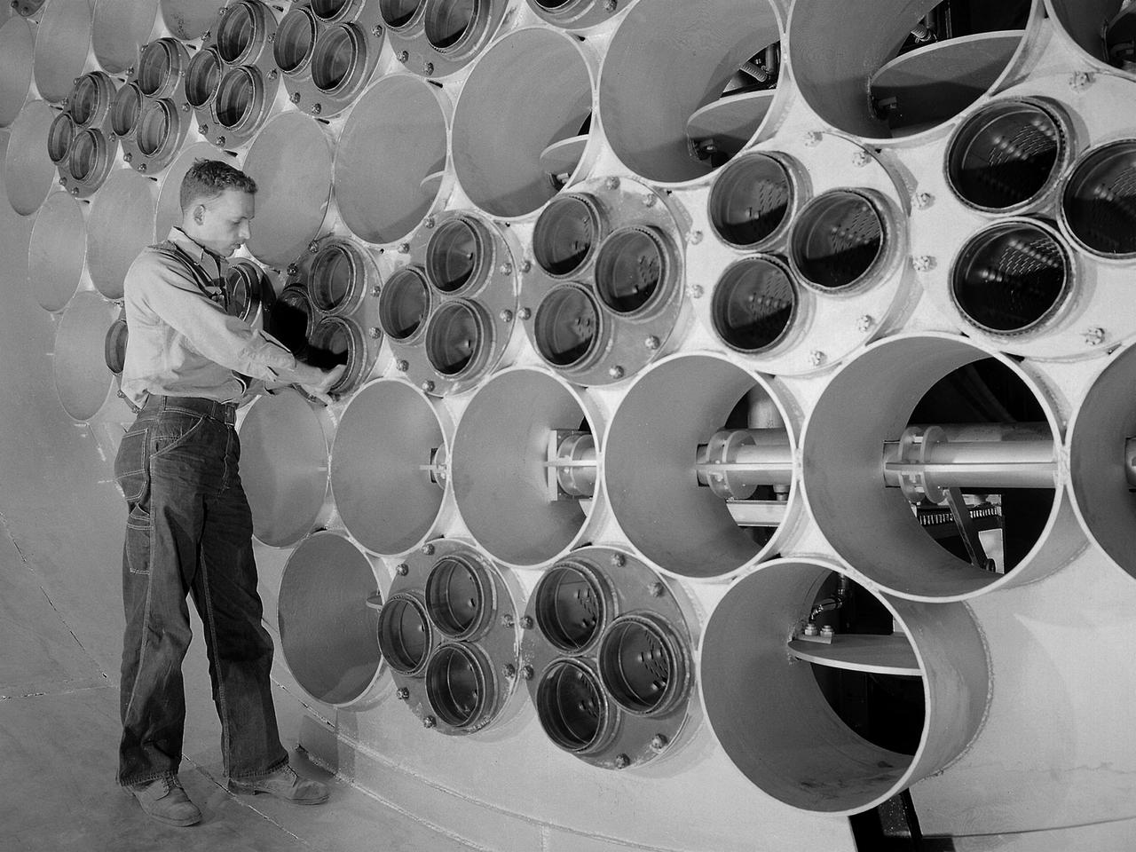
A technician at the National Advisory Committee for Aeronautics (NACA) Lewis Flight Propulsion Laboratory examines one of the massive axial-flow compressor stages that created the high-speed air flow through the 8- by 6-Foot Supersonic Wind Tunnel. The tunnel’s first run was on April 3, 1949, just over a week before this photograph was taken. The 8- by 6 was the laboratory’s first large supersonic wind tunnel and the NACA’s largest supersonic tunnel at the time. The 8- by 6-foot tunnel was originally an open-throat non-return tunnel. The supersonic air flow was blown through the tubular facility and expelled out the other end into the atmosphere with a roar. Complaints from the local community led to the addition of a muffler at the tunnel exit in 1956 and the eventual addition of a return leg. The return leg allowed the tunnel to be operated as either an open system with large doors venting directly to the atmosphere for propulsion system tests or as a closed loop for aerodynamic tests. The air flow was generated by a large seven-stage axial-flow compressor, seen in this photograph, that was powered by three electric motors with a combined 87,000 horsepower. The system required 36,000 kilowatts of power per hour to generate wind velocities of Mach 1.5, and 72,000 kilowatts per hour for Mach 2.0.
Orion Capsule and Launch Abort System (LAS) installed in the NASA Glenn 8x6 Supersonic Wind Tunnel (SWT) for testing. 8x6 supersonic wind tunnel test section with the launch abort system for the Orion capsule
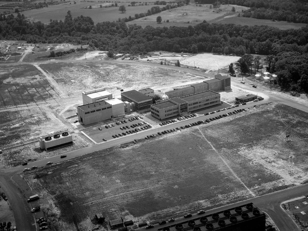
Aerial view of the 8- by 6-Foot Supersonic Wind Tunnel in its original configuration at the National Advisory Committee for Aeronautics (NACA) Lewis Flight Propulsion Laboratory. The 8- by 6 was the laboratory’s first large supersonic wind tunnel. It was also the NACA’s most powerful supersonic tunnel, and its first facility capable of running an engine at supersonic speeds. The 8- by 6-foot tunnel has been used to study inlets and exit nozzles, fuel injectors, flameholders, exit nozzles, and controls on ramjet and turbojet propulsion systems. The 8- by 6 was originally an open-throat and non-return tunnel. This meant that the supersonic air flow was blown through the test section and out the other end into the atmosphere. In this photograph, the three drive motors in the structure at the left supplied power to the seven-stage axial-flow compressor in the light-colored structure. The air flow passed through flexible walls which were bent to create the desired speed. The test article was located in the 8- by 6-foot stainless steel test section located inside the steel pressure chamber at the center of this photograph. The tunnel dimensions were then gradually increased to slow the air flow before it exited into the atmosphere. The large two-story building in front of the tunnel was used as office space for the researchers.
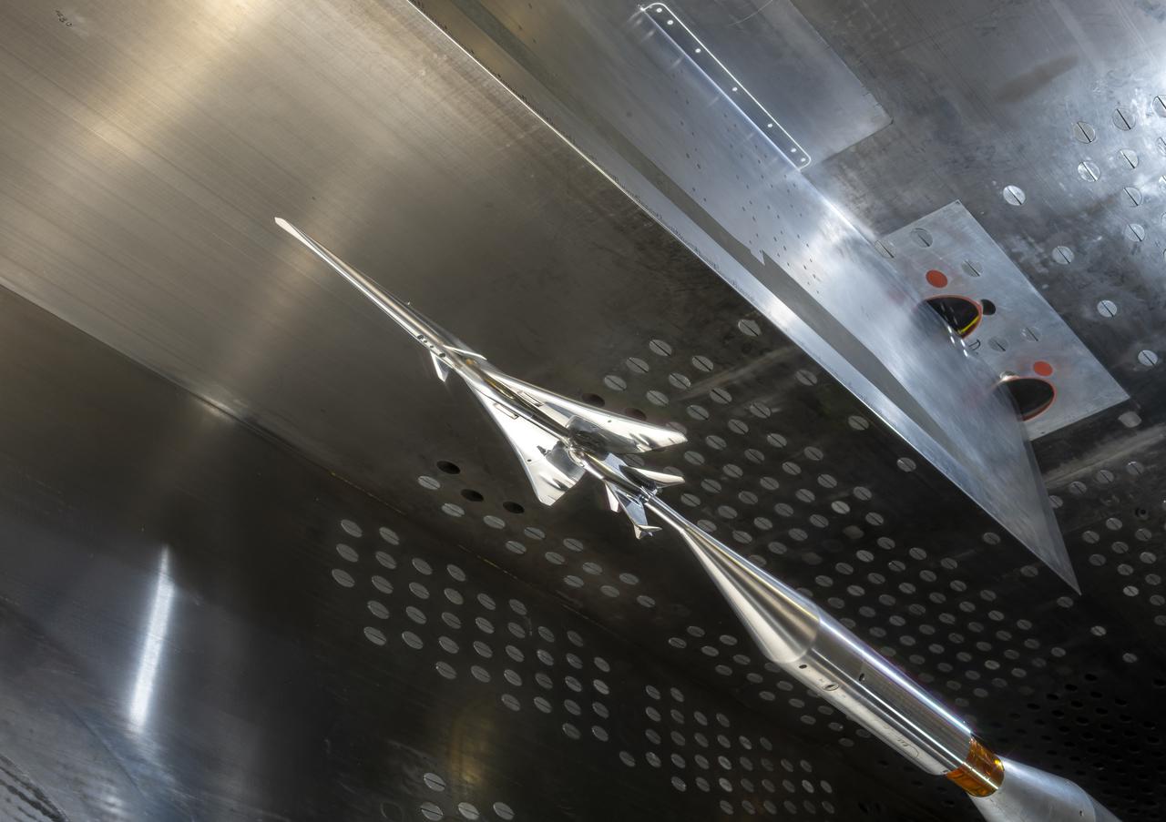
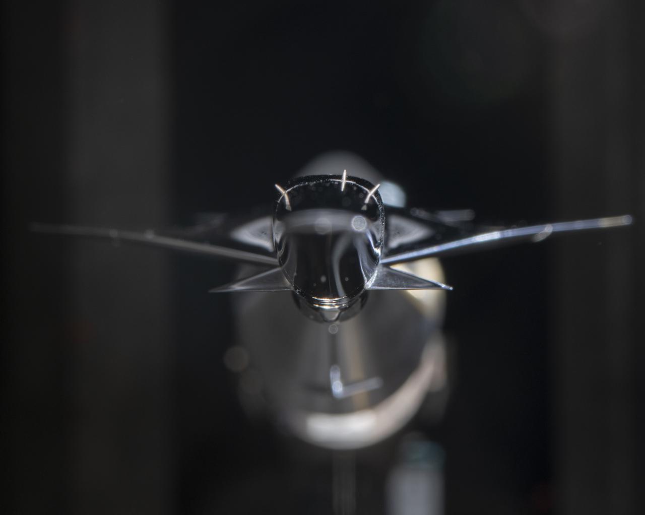
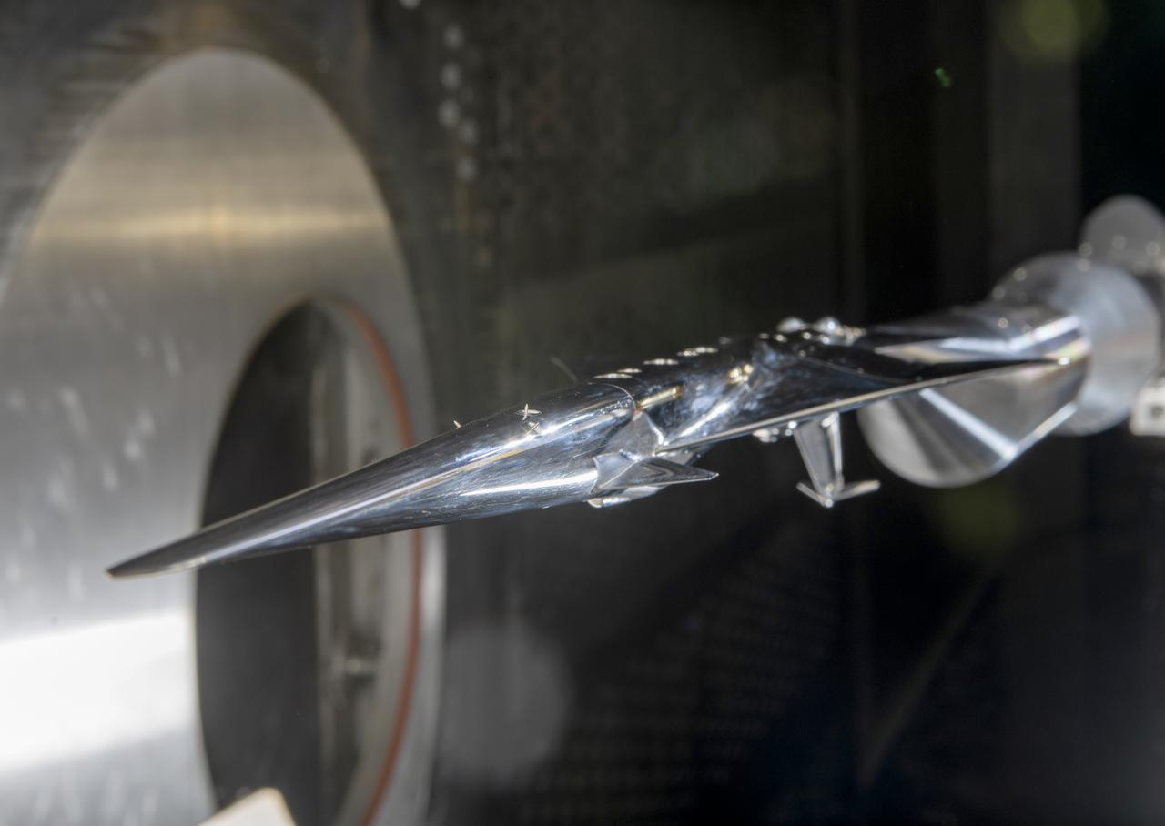
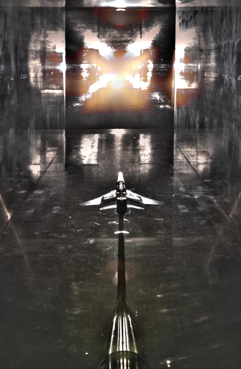
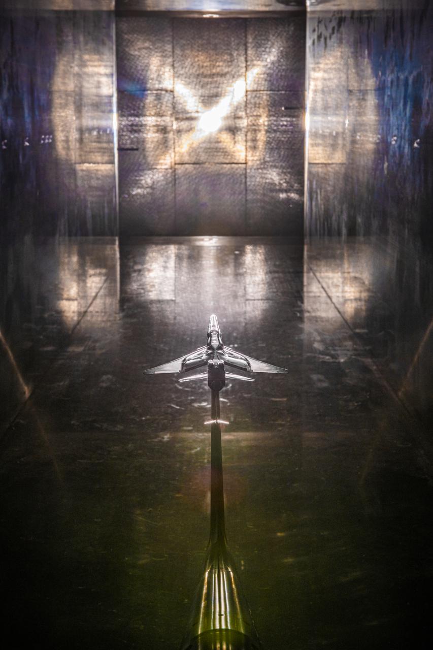
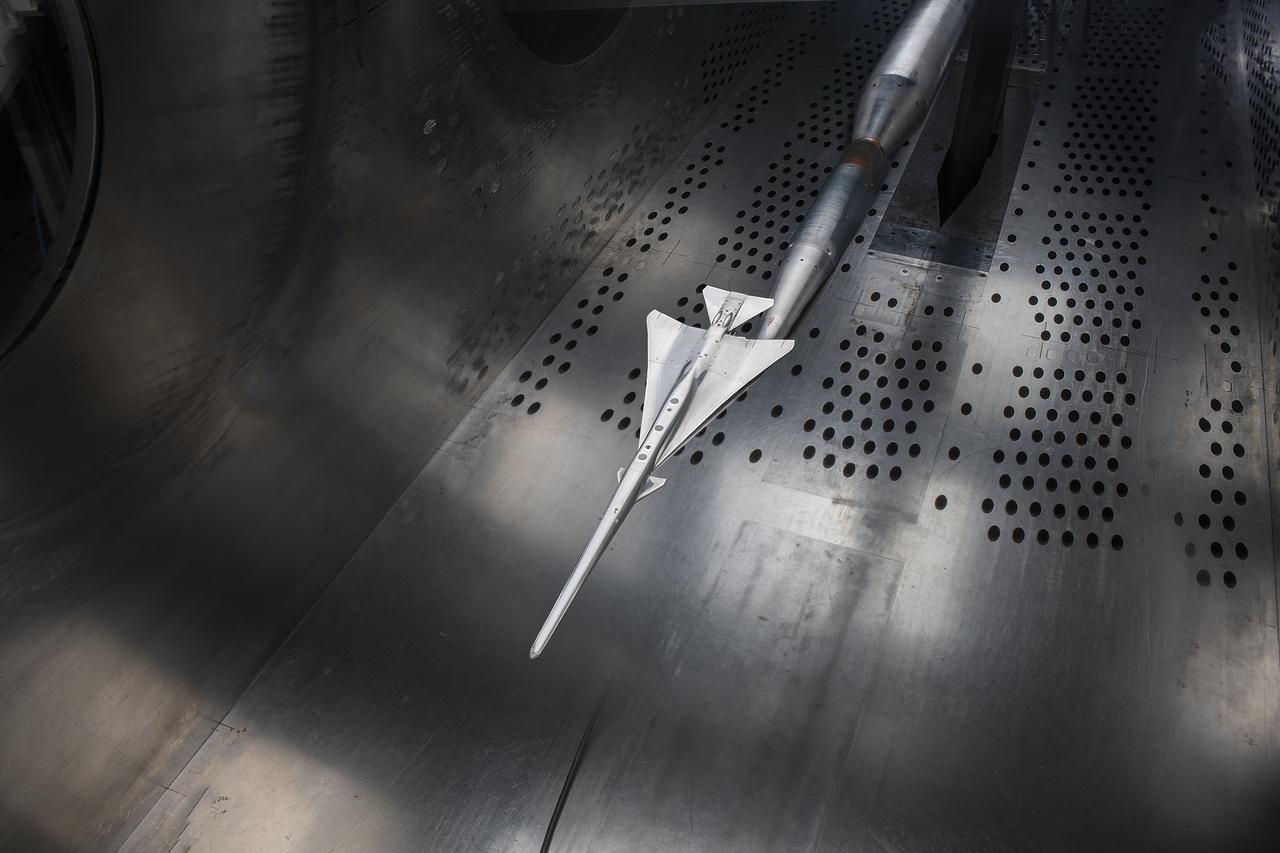
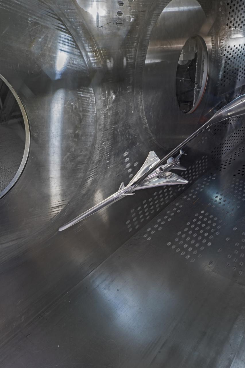
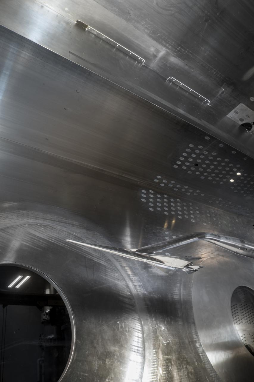
The X-59 Commercial Supersonic Transport model is installed upside down in the test section of the GRC 8x6 Supersonic wind tunnel. The blade hanging from the top of the tunnel will be measuring the shock waves coming from the bottom of the model during testing. The shock waves coming from the bottom of the model represent the sonic boom reaching the ground during flight. The shape of the model is designed so as to greatly reduce the shock waves to prevent the typical boom coming from a supersonic aircraft. Commercial Supersonic Transport, CST Project, X-59 Sonic Boom Test Model, in the 8x6-foot Supersonic Wind Tunnel, SWT
Commercial Supersonic Transport, CST Project, X-59 Sonic Boom Test Model, in the 8x6-foot Supersonic Wind Tunnel, SWT
Commercial Supersonic Transport, CST Project, X-59 Sonic Boom Test Model, in the 8x6-foot Supersonic Wind Tunnel, SWT
Commercial Supersonic Transport, CST Project, X-59 Sonic Boom Test Model, in the 8x6-foot Supersonic Wind Tunnel, SWT
Commercial Supersonic Transport, CST Project, X-59 Sonic Boom Test Model, in the 8x6-foot Supersonic Wind Tunnel, SWT
Commercial Supersonic Transport, CST Project, X-59 Sonic Boom Test Model, in the 8x6-foot Supersonic Wind Tunnel, SWT
Commercial Supersonic Transport, CST Project, X-59 Sonic Boom Test Model, in the 8x6-foot Supersonic Wind Tunnel, SWT

Commercial Supersonic Transport, CST Project, X-59 Sonic Boom Test Model, in the 8x6-foot Supersonic Wind Tunnel, SWT
Commercial Supersonic Transport, CST Project, X-59 Sonic Boom Test Model, in the 8x6-foot Supersonic Wind Tunnel, SWT
Commercial Supersonic Transport, CST Project, X-59 Sonic Boom Test Model, in the 8x6-foot Supersonic Wind Tunnel, SWT

Commercial Supersonic Transport, CST Project, X-59 Sonic Boom Test Model, in the 8x6-foot Supersonic Wind Tunnel, SWT
Commercial Supersonic Transport, CST Project, X-59 Sonic Boom Test Model, in the 8x6-foot Supersonic Wind Tunnel, SWT
Commercial Supersonic Transport, CST Project, X-59 Sonic Boom Test Model, in the 8x6-foot Supersonic Wind Tunnel, SWT
Commercial Supersonic Transport, CST Project, X-59 Sonic Boom Test Model, in the 8x6-foot Supersonic Wind Tunnel, SWT
Commercial Supersonic Transport, CST Project, X-59 Sonic Boom Test Model, in the 8x6-foot Supersonic Wind Tunnel, SWT
Commercial Supersonic Transport, CST Project, X-59 Sonic Boom Test Model, in the 8x6-foot Supersonic Wind Tunnel, SWT
Commercial Supersonic Transport, CST Project, X-59 Sonic Boom Test Model, in the 8x6-foot Supersonic Wind Tunnel, SWT

Commercial Supersonic Transport, CST Project, X-59 Sonic Boom Test Model, in the 8x6-foot Supersonic Wind Tunnel, SWT
Commercial Supersonic Transport, CST Project, X-59 Sonic Boom Test Model, in the 8x6-foot Supersonic Wind Tunnel, SWT

Commercial Supersonic Transport, CST Project, X-59 Sonic Boom Test Model, in the 8x6-foot Supersonic Wind Tunnel, SWT
Commercial Supersonic Transport, CST Project, X-59 Sonic Boom Test Model, in the 8x6-foot Supersonic Wind Tunnel, SWT
The 8- by 6-Foot Supersonic Wind Tunnel at the National Advisory Committee for Aeronautics (NACA) Lewis Flight Propulsion Laboratory was the largest supersonic wind tunnel in the nation at the time and the only one able to test full-scale engines at supersonic speeds. The 8- by 6 was designed as a non-return and open-throat tunnel. A large compressor created the air flow at one end of the tunnel, squeezed the flow to increase its velocity just before the test section, then reduced the velocity, and expelled it into the atmosphere at the other end of the tunnel. This design worked well for initial aerodynamic testing, but the local community was literally rattled by the noise and vibrations when researchers began running engines in the test section in January 1950. The NACA’s most modern wind tunnel was referred to as “an 87,000-horsepower bugle aimed at the heart of Cleveland.” NACA Lewis responded to the complaints by adding an acoustic housing at the end of the tunnel to dampen the noise. The structure included resonator chambers and a reinforced concrete muffler structure. Modifications continued over the years. A return leg was added, and a second test section, 9 -by 15-foot, was incorporated in the return leg in the 1960s. Since its initial operation in 1948, the 8- by 6-foot tunnel has been aggressively used to support the nation's aeronautics and space programs for the military, industry, and academia.
Counter Rotating Propeller Model in the NASA Glenn 8x6-Foot Supersonic Wind Tunnel
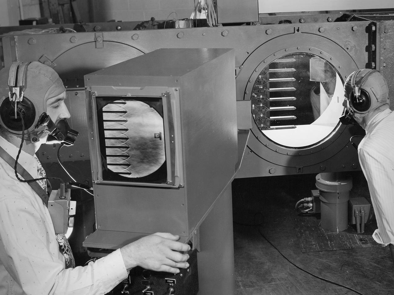
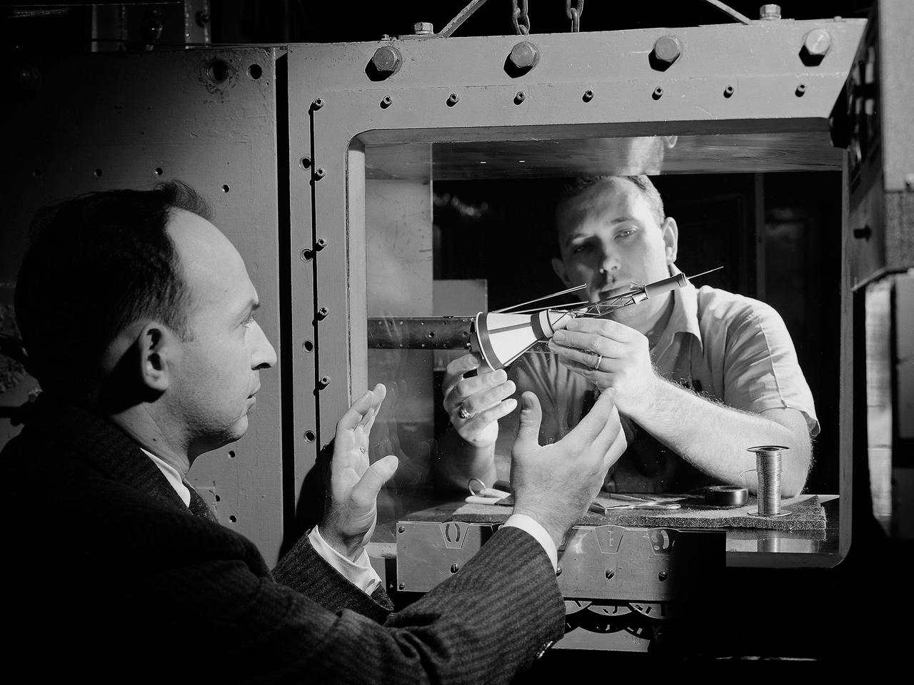
Engineers calibrate one of three small supersonic wind tunnels that were collectively referred to as the “Stack Tunnels” at the National Advisory Committee for Aeronautics (NACA) Lewis Flight Propulsion Laboratory. In late 1945 NACA Lewis reorganized its staff and began constructing a new wave of facilities to address high-speed flight and the turbojet and rocket technologies that emerged during World War II. While design work began on what would eventually become the 8- by 6-Foot Supersonic Wind Tunnel, NACA Lewis quickly built several small supersonic tunnels. These small facilities utilized the Altitude Wind Tunnel’s massive air handling equipment. Three of the small tunnels were built vertically on top of each other and thus were known as the Stack Tunnels. The first of the Stack Tunnels was an 18- by 18-inch tunnel that began operating in August 1945 at speeds up to Mach 1.91. The second tunnel, whose 24- by 24-inch test section is shown here, was added in 1949. It could generate air flows up to Mach 3.96. A third tunnel with an 18- by 18-inch test section began operating in 1951 with speeds up to Mach 3.05. The small tunnels were used until the early 1960s to study the aerodynamic characteristics of supersonic inlets and exits. The technician to the left in this photograph is operating a Schlieren camera to view the air flow dynamics inside the 24- by 24-inch test section. The technician on the right is viewing the pronged test article through the circular window. They are calibrating the tunnel and its equipment to prepare for the initial test runs.

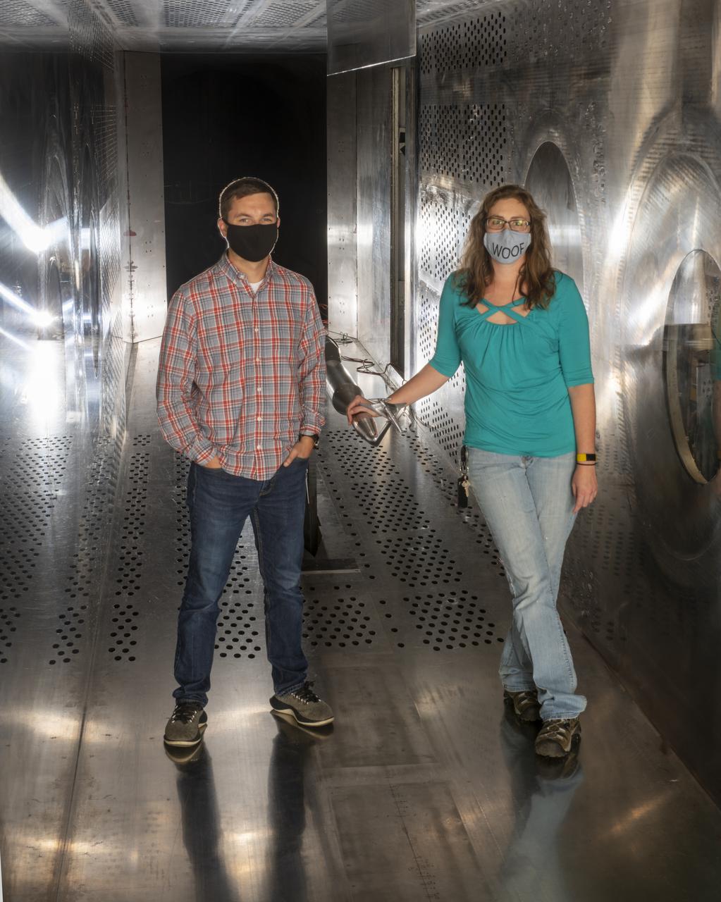
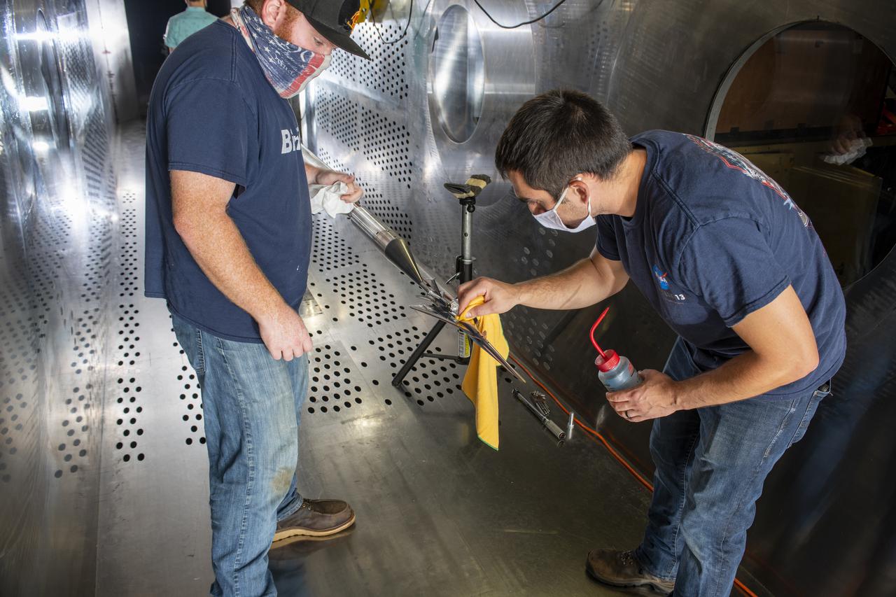
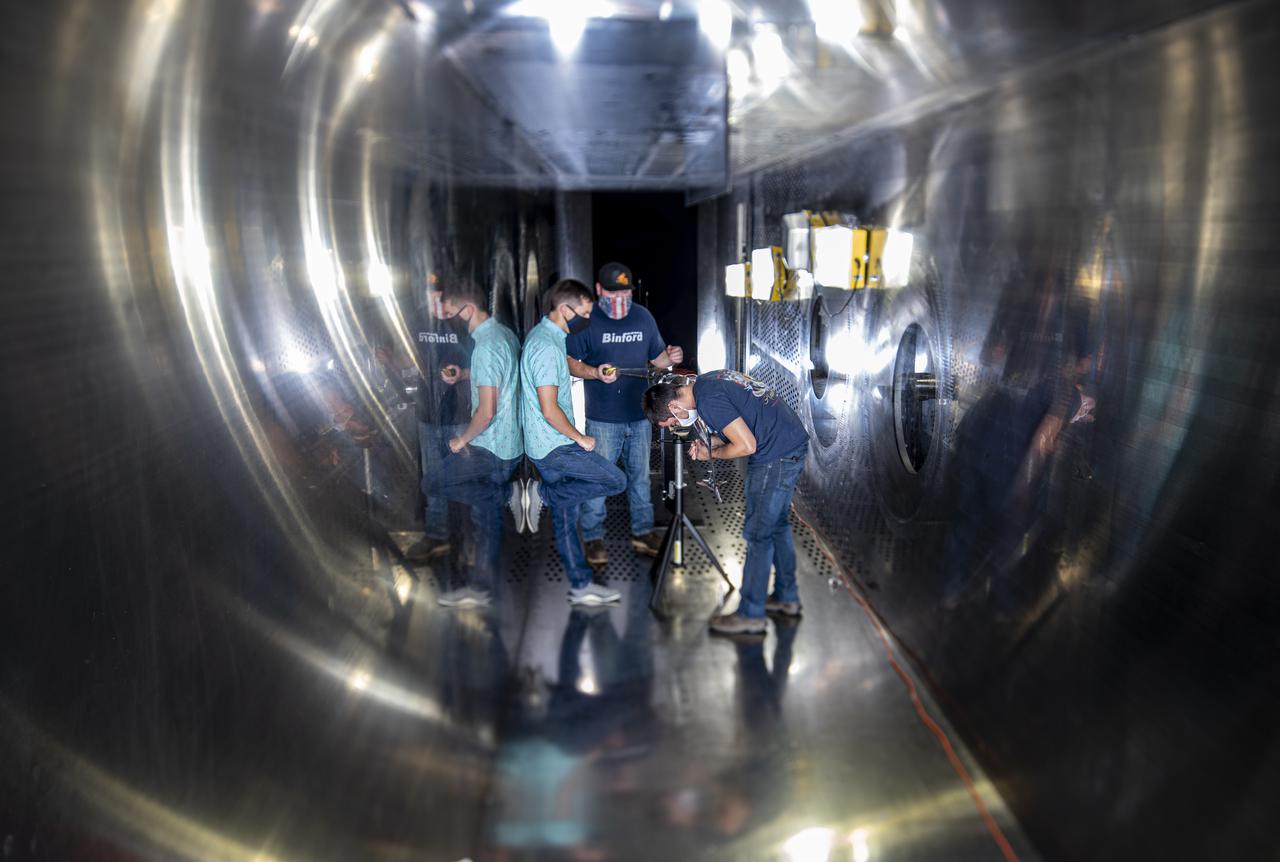
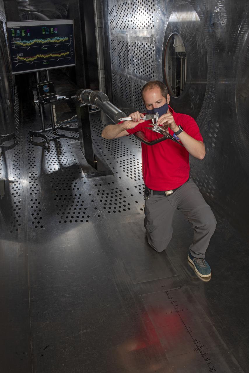
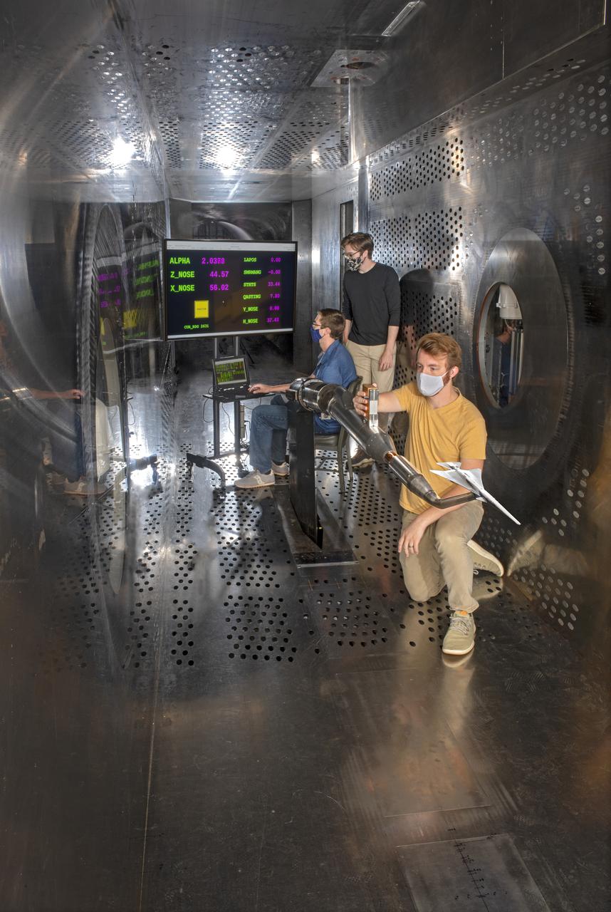
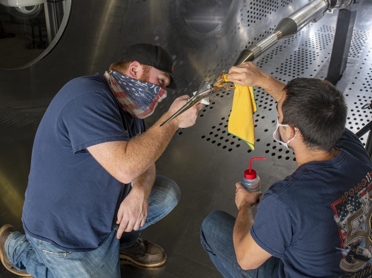
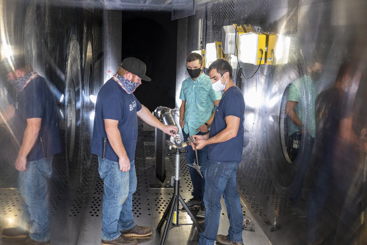
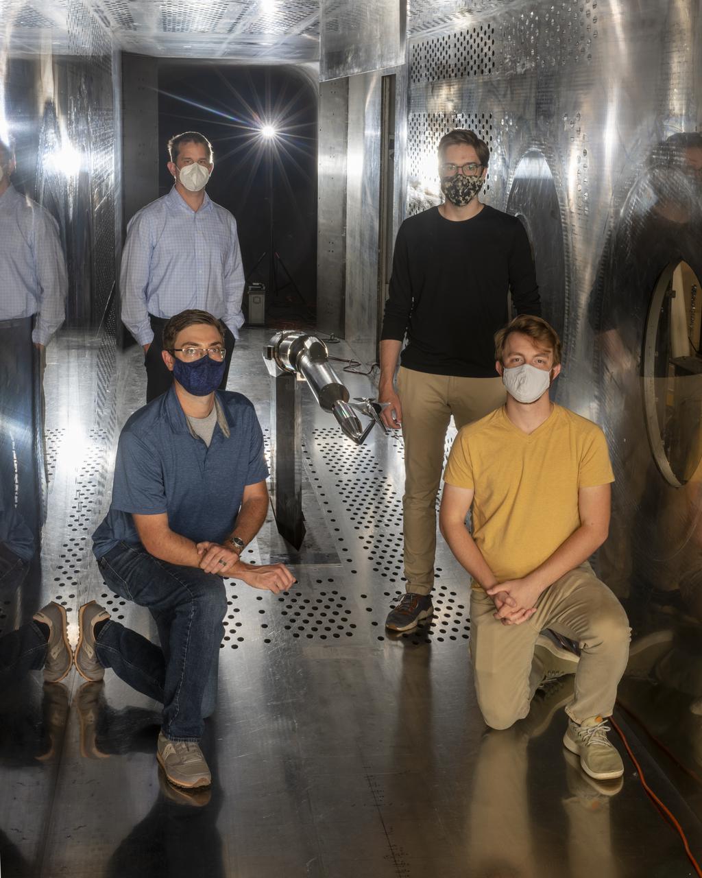
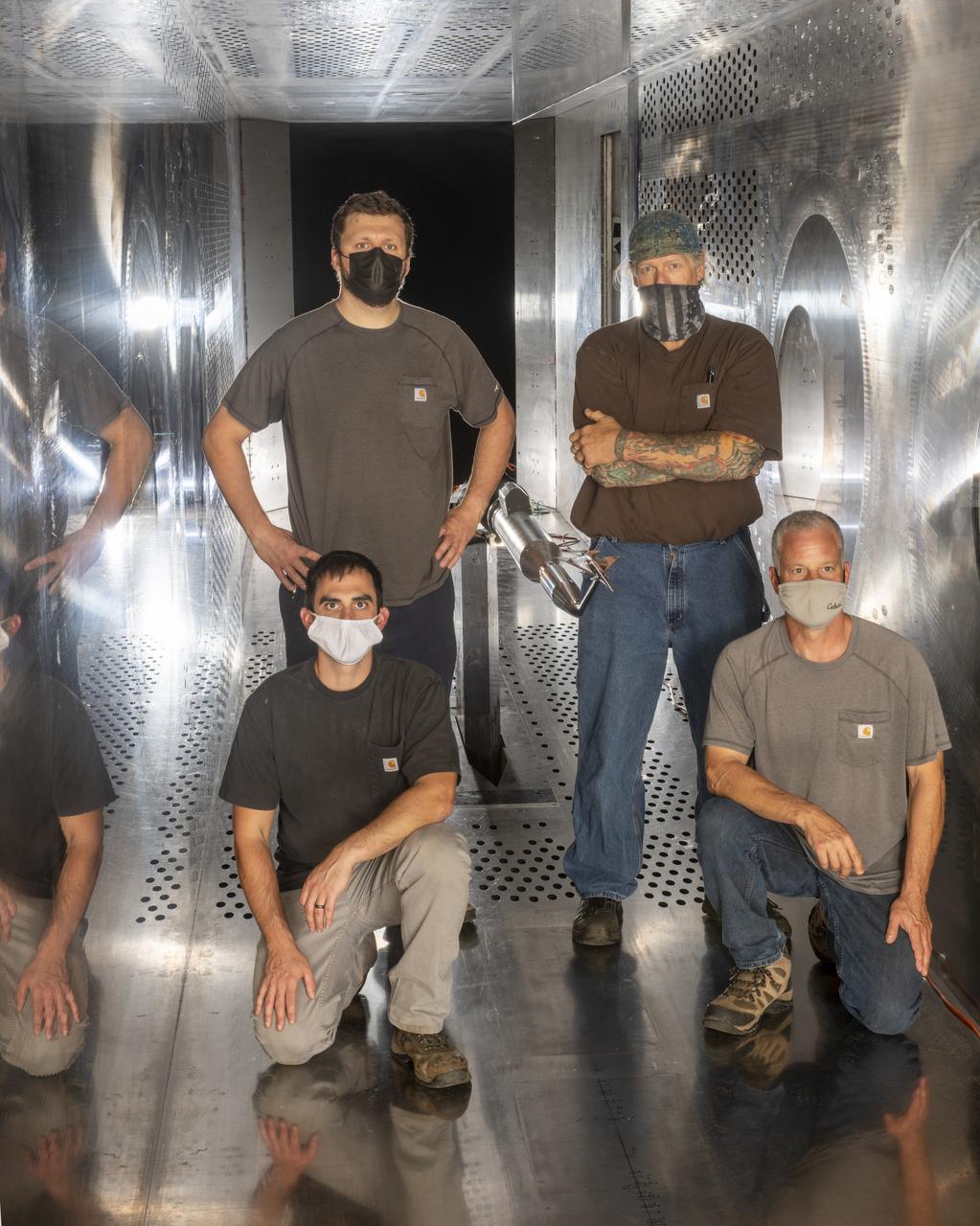
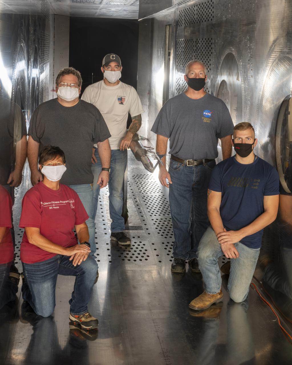
An aerospace research engineer and technicians inspect the X-59 Commercial Supersonic Transport model’s installation and alignment before testing. The blade hanging from the top of the tunnel will be measuring the shock waves coming from the model during testing. The intent is to develop a supersonic aircraft with less sonic boom. Commercial Supersonic Transport, CST Project, X-59 Sonic Boom Test Model, in the 8x6-foot Supersonic Wind Tunnel, SWT
Commercial Supersonic Transport, CST Project, X-59 Sonic Boom Test Model, in the 8x6-foot Supersonic Wind Tunnel, SWT
Commercial Supersonic Transport, CST Project, X-59 Sonic Boom Test Model, in the 8x6-foot Supersonic Wind Tunnel, SWT
Commercial Supersonic Transport, CST Project, X-59 Sonic Boom Test Model, in the 8x6-foot Supersonic Wind Tunnel, SWT
Commercial Supersonic Transport, CST Project, X-59 Sonic Boom Test Model, in the 8x6-foot Supersonic Wind Tunnel, SWT
Commercial Supersonic Transport, CST Project, X-59 Sonic Boom Test Model, in the 8x6-foot Supersonic Wind Tunnel, SWT
Commercial Supersonic Transport, CST Project, X-59 Sonic Boom Test Model, in the 8x6-foot Supersonic Wind Tunnel, SWT
Commercial Supersonic Transport, CST Project, X-59 Sonic Boom Test Model, in the 8x6-foot Supersonic Wind Tunnel, SWT
Commercial Supersonic Transport, CST Project, X-59 Sonic Boom Test Model, in the 8x6-foot Supersonic Wind Tunnel, SWT

Commercial Supersonic Transport, CST Project, X-59 Sonic Boom Test Model, in the 8x6-foot Supersonic Wind Tunnel, SWT
Commercial Supersonic Transport, CST Project, X-59 Sonic Boom Test Model, in the 8x6-foot Supersonic Wind Tunnel, SWT
Commercial Supersonic Transport, CST Project, X-59 Sonic Boom Test Model, in the 8x6-foot Supersonic Wind Tunnel, SWT
Commercial Supersonic Transport, CST Project, X-59 Sonic Boom Test Model, in the 8x6-foot Supersonic Wind Tunnel, SWT
Commercial Supersonic Transport, CST Project, X-59 Sonic Boom Test Model, in the 8x6-foot Supersonic Wind Tunnel, SWT
Commercial Supersonic Transport, CST Project, X-59 Sonic Boom Test Model, in the 8x6-foot Supersonic Wind Tunnel, SWT
Commercial Supersonic Transport, CST Project, X-59 Sonic Boom Test Model, in the 8x6-foot Supersonic Wind Tunnel, SWT
Commercial Supersonic Transport, CST Project, X-59 Sonic Boom Test Model, in the 8x6-foot Supersonic Wind Tunnel, SWT
Commercial Supersonic Transport, CST Project, X-59 Sonic Boom Test Model, in the 8x6-foot Supersonic Wind Tunnel, SWT
Commercial Supersonic Transport, CST Project, X-59 Sonic Boom Test Model, in the 8x6-foot Supersonic Wind Tunnel, SWT
Commercial Supersonic Transport, CST Project, X-59 Sonic Boom Test Model, in the 8x6-foot Supersonic Wind Tunnel, SWT
Commercial Supersonic Transport, CST Project, X-59 Sonic Boom Test Model, in the 8x6-foot Supersonic Wind Tunnel, SWT
Commercial Supersonic Transport, CST Project, X-59 Sonic Boom Test Model, in the 8x6-foot Supersonic Wind Tunnel, SWT
Commercial Supersonic Transport, CST Project, X-59 Sonic Boom Test Model, in the 8x6-foot Supersonic Wind Tunnel, SWT
Commercial Supersonic Transport, CST Project, X-59 Sonic Boom Test Model, in the 8x6-foot Supersonic Wind Tunnel, SWT
Commercial Supersonic Transport, CST Project, X-59 Sonic Boom Test Model, in the 8x6-foot Supersonic Wind Tunnel, SWT
Commercial Supersonic Transport, CST Project, X-59 Sonic Boom Test Model, in the 8x6-foot Supersonic Wind Tunnel, SWT
Commercial Supersonic Transport, CST Project, X-59 Sonic Boom Test Model, in the 8x6-foot Supersonic Wind Tunnel, SWT
Commercial Supersonic Transport, CST Project, X-59 Sonic Boom Test Model, in the 8x6-foot Supersonic Wind Tunnel, SWT
Commercial Supersonic Transport, CST Project, X-59 Sonic Boom Test Model, in the 8x6-foot Supersonic Wind Tunnel, SWT
Commercial Supersonic Transport, CST Project, X-59 Sonic Boom Test Model, in the 8x6-foot Supersonic Wind Tunnel, SWT
Commercial Supersonic Transport, CST Project, X-59 Sonic Boom Test Model, in the 8x6-foot Supersonic Wind Tunnel, SWT
Commercial Supersonic Transport, CST Project, X-59 Sonic Boom Test Model, in the 8x6-foot Supersonic Wind Tunnel, SWT
Commercial Supersonic Transport, CST Project, X-59 Sonic Boom Test Model, in the 8x6-foot Supersonic Wind Tunnel, SWT
Commercial Supersonic Transport, CST Project, X-59 Sonic Boom Test Model, in the 8x6-foot Supersonic Wind Tunnel, SWT
Commercial Supersonic Transport, CST Project, X-59 Sonic Boom Test Model, in the 8x6-foot Supersonic Wind Tunnel, SWT
Commercial Supersonic Transport, CST Project, X-59 Sonic Boom Test Model, in the 8x6-foot Supersonic Wind Tunnel, SWT
Commercial Supersonic Transport, CST Project, X-59 Sonic Boom Test Model, in the 8x6-foot Supersonic Wind Tunnel, SWT
Commercial Supersonic Transport, CST Project, X-59 Sonic Boom Test Model, in the 8x6-foot Supersonic Wind Tunnel, SWT
Commercial Supersonic Transport, CST Project, X-59 Sonic Boom Test Model, in the 8x6-foot Supersonic Wind Tunnel, SWT
Commercial Supersonic Transport, CST Project, X-59 Sonic Boom Test Model, in the 8x6-foot Supersonic Wind Tunnel, SWT
Commercial Supersonic Transport, CST Project, X-59 Sonic Boom Test Model, in the 8x6-foot Supersonic Wind Tunnel, SWT
Commercial Supersonic Transport, CST Project, X-59 Sonic Boom Test Model, in the 8x6-foot Supersonic Wind Tunnel, SWT

Mars Science Laboratory (MSL) Flexible Canopy Testing in the Glenn Research Center, 10x10 Supersonic Wind Tunnel
The 10- by 10-Foot Supersonic Wind Tunnel at the NACA Lewis Flight Propulsion Laboratory was built under the Congressional Unitary Plan Act which coordinated wind tunnel construction at the NACA, Air Force, industry, and universities. The 10- by 10, which began operation in 1956, was the largest of the three NACA tunnels built under the act. Researchers could test engines up to five feet in diameter in the 10- by 10-foot test section. A 250,000-horsepower axial-flow compressor fan can generate airflows up to Mach 3.5 through the test section. The incoming air must be dehumidified and cooled so that the proper conditions are present for the test. A large air dryer with 1,890 tons of activated alumina soaks up 1.5 tons of water per minute from the airflow. A cooling apparatus equivalent to 250,000 household air conditioners is used to cool the air. The air heater is located just upstream from the test section. Natural gas is combusted in the tunnel to increase the air temperature. The system could only be employed when the tunnel was run in its closed-circuit propulsion mode.
National Aeronautics and Space Administration (NASA) researchers install a small-scale model of the capsule for Project Mercury in the 1- by 1-Foot Supersonic Wind Tunnel at the Lewis Research Center. NASA Lewis conducted a variety of tests for Project Mercury, including retrorocket calibration, escape tower engine performance, and separation of the capsule from simulated Atlas and Redstone boosters. The test of this capsule and escape tower model in the 1- by 1-foot tunnel were run in January and February 1960. The 1-by 1-Foot Supersonic Wind Tunnel had a 15-inch long test section, seen here, that was one foot wide and one foot high. The sides were made of glass to allow cameras to capture the supersonic air flow over the models. The tunnel could generate air flows from Mach 1.3 to 3.0. At the time, it was one of nine small supersonic wind tunnels at Lewis. These tunnels used the exhauster and compressor equipment of the larger facilities. The 1- by 1 tunnel, which began operating in the early 1950s, was built inside a test cell in the expansive Engine Research Building. During the 1950s the 1- by 1 was used to study a variety of inlets, nozzles, and cones for missiles and scramjets. The Mercury capsule tests were among the last at the facility for many years. The tunnel was mothballed in 1960. The 1- by 1 was briefly restored in 1972, then brought back online for good in 1979. The facility has maintained a brisk operating schedule ever since.
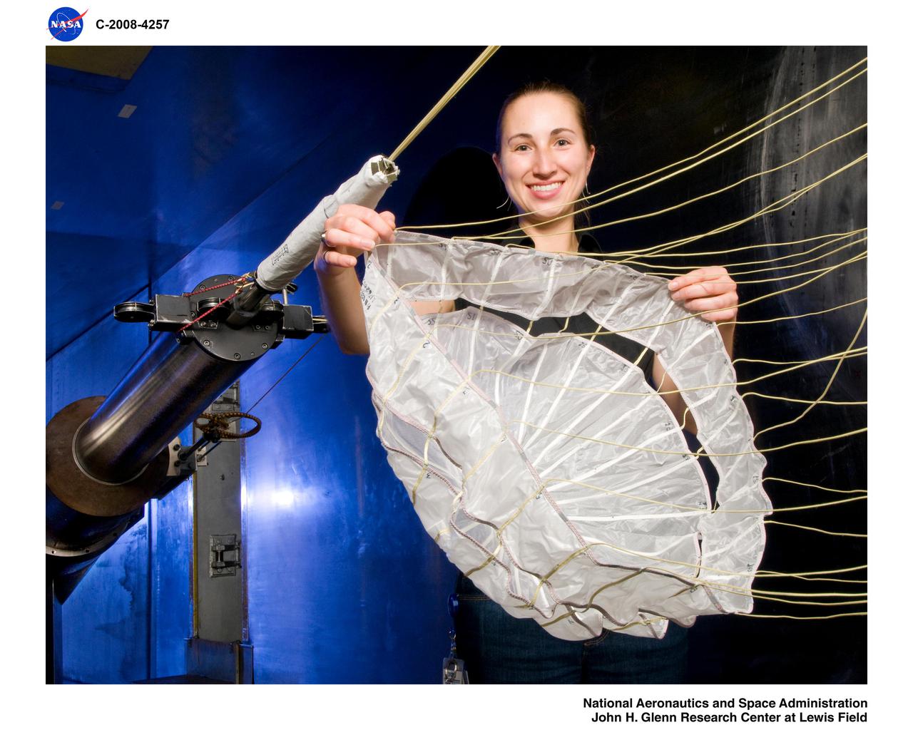
Mars Science Laboratory, MSL Flexible Canopy Test in the Glenn Research Center, 10x10 Supersonic Wind Tunnel
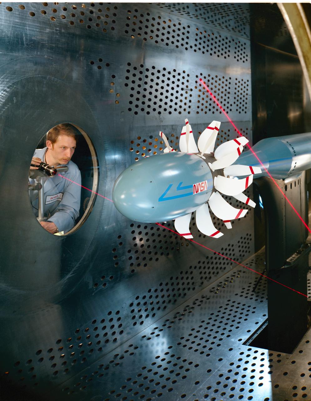
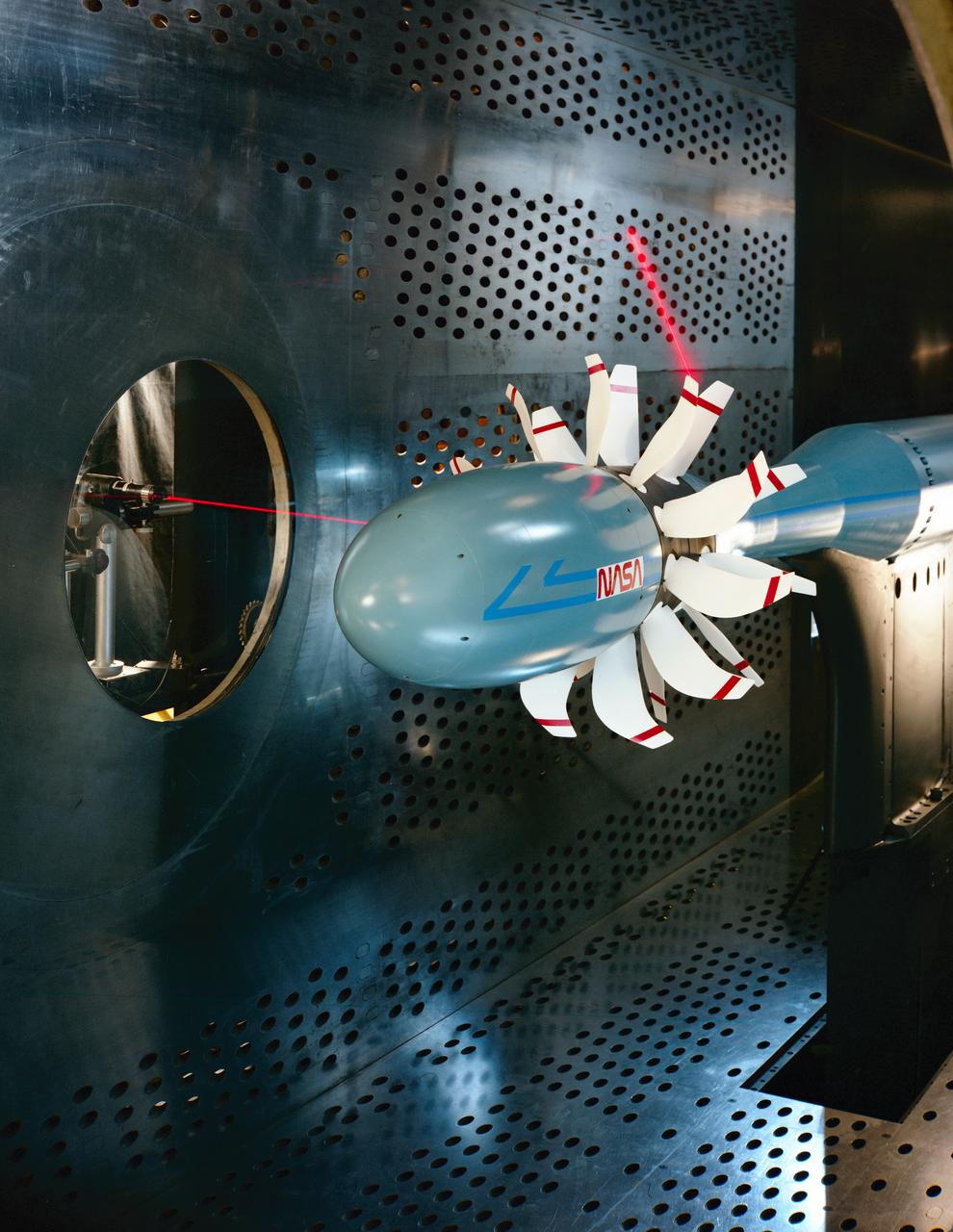
Laser based blade deflection measurement system on Counter Rotation Pusher Propeller model in 8x6 SWT (Supersonic Wind Tunnel)
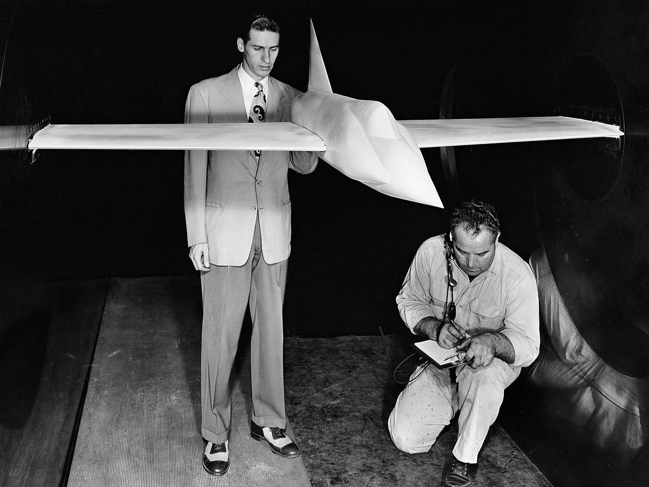
A .10-scale model of Convair’s XF-102 in the 8- by 6-Foot Supersonic Wind Tunnel at the National Advisory Committee for Aeronautics (NACA) Lewis Flight Propulsion Laboratory for jet exit studies. The XF-102 was a prototype of the F-102 Delta Dagger. The F-102 served as an interceptor against long range bombers from the Soviet Union. The aircraft was powered by a Pratt and Whitney J57 turbojet. The first prototype crashed two weeks after is first flight on October 24, 1953, just months after this photograph. Engineers then incorporated the fixed-wing design to reduce drag at supersonic speeds. The production model F-102 became the first delta-wing supersonic aircraft in operation. The 8- by 6-Foot Supersonic Wind Tunnel is used to study propulsion systems, including inlets and exit nozzles, combustion fuel injectors, flame holders, exit nozzles, and controls on ramjet and turbojet engines. Flexible sidewalls alter the tunnel’s nozzle shape to vary the Mach number during operation. A seven-stage axial compressor, driven by three electric motors that yield a total of 87,000 horsepower, generates air speeds from Mach 0.36 to 2.0.
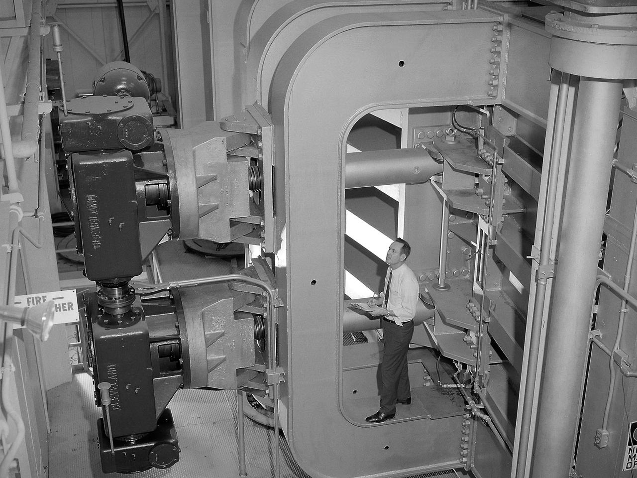
Screwjacks located on the exterior of the second throat section in the 10- by 10-Foot Supersonic Wind Tunnel at the National Aeronautics and Space Administration (NASA) Lewis Research Center. The 10- by 10 tunnel was the most powerful propulsion wind tunnel in the country when it began operating in 1956. The facility can generate wind speeds from Mach 3 to 3.5. A flexible wall nozzle located just upstream from the test section can be adjusted using screw jacks to produce the desired air flow. The 61-foot long second throat, seen here from the outside, was located just beyond the test section. It slows the supersonic air flow down to prevent shock waves. The second throat’s side walls can be adjusted up to three inches on each side using these electrically-driven screwjacks. The air and the 1.25-inch thick walls are cooled by water injection. During the 1960s the 10- by 10-foot tunnel supported the development of virtually all US launch vehicle systems. It was used for Atlas-Centaur, Saturn rockets, and Atlas-Agena testing.
Commercial Supersonic Transport, CST Project, X-59 Sonic Boom Test Model, in the 8x6-foot Supersonic Wind Tunnel, SWT
Commercial Supersonic Transport, CST Project, X-59 Sonic Boom Test Model, in the 8x6-foot Supersonic Wind Tunnel, SWT
Commercial Supersonic Transport, CST Project, X-59 Sonic Boom Test Model, in the 8x6-foot Supersonic Wind Tunnel, SWT

Commercial Supersonic Transport, CST Project, X-59 Sonic Boom Test Model, in the 8x6-foot Supersonic Wind Tunnel, SWT
Commercial Supersonic Transport, CST Project, X-59 Sonic Boom Test Model, in the 8x6-foot Supersonic Wind Tunnel, SWT
Commercial Supersonic Transport, CST Project, X-59 Sonic Boom Test Model, in the 8x6-foot Supersonic Wind Tunnel, SWT
Commercial Supersonic Transport, CST Project, X-59 Sonic Boom Test Model, in the 8x6-foot Supersonic Wind Tunnel, SWT
Commercial Supersonic Transport, CST Project, X-59 Sonic Boom Test Model, in the 8x6-foot Supersonic Wind Tunnel, SWT
Commercial Supersonic Transport, CST Project, X-59 Sonic Boom Test Model, in the 8x6-foot Supersonic Wind Tunnel, SWT