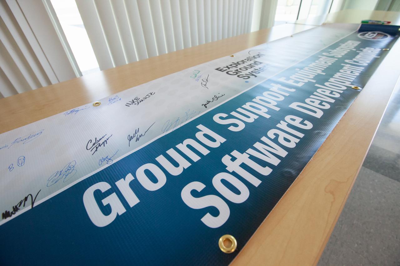
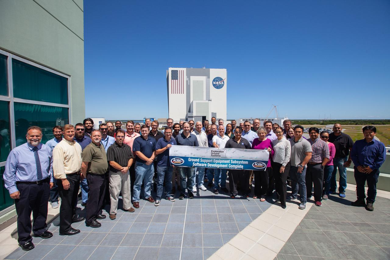
KSC Engineering Banner Event A banner signing event was held April 22, 2019, at NASA’s Kennedy Space Center in Florida, to mark the accomplishments of the Kennedy engineering team that supported the Ground Support Equipment (GSE) Subsystem Software development. The team gathered in the observation area of the Operations Support Building II with a view of the Vehicle Assembly Building behind them. This team includes the software leads, local developers, remote developers, modelers, project engineers, software quality assurance, build team members, integrators, system engineers, a chief engineer and some software managers. There are 60 unique instances of GSE Subsystem Software code. As of today, 58 of those 60 instances have completed software Level 5 Verification (L5V) and are in the process of completing Subsystem Verification & Validation.